JP2020501711A - Deployment systems, tools, and methods for delivering an anchoring device for a prosthetic valve - Google Patents
Deployment systems, tools, and methods for delivering an anchoring device for a prosthetic valveDownload PDFInfo
- Publication number
- JP2020501711A JP2020501711AJP2019531963AJP2019531963AJP2020501711AJP 2020501711 AJP2020501711 AJP 2020501711AJP 2019531963 AJP2019531963 AJP 2019531963AJP 2019531963 AJP2019531963 AJP 2019531963AJP 2020501711 AJP2020501711 AJP 2020501711A
- Authority
- JP
- Japan
- Prior art keywords
- delivery catheter
- anchoring device
- valve
- ring
- heart
- Prior art date
- Legal status (The legal status is an assumption and is not a legal conclusion. Google has not performed a legal analysis and makes no representation as to the accuracy of the status listed.)
- Granted
Links
Images


Classifications
- A—HUMAN NECESSITIES
- A61—MEDICAL OR VETERINARY SCIENCE; HYGIENE
- A61F—FILTERS IMPLANTABLE INTO BLOOD VESSELS; PROSTHESES; DEVICES PROVIDING PATENCY TO, OR PREVENTING COLLAPSING OF, TUBULAR STRUCTURES OF THE BODY, e.g. STENTS; ORTHOPAEDIC, NURSING OR CONTRACEPTIVE DEVICES; FOMENTATION; TREATMENT OR PROTECTION OF EYES OR EARS; BANDAGES, DRESSINGS OR ABSORBENT PADS; FIRST-AID KITS
- A61F2/00—Filters implantable into blood vessels; Prostheses, i.e. artificial substitutes or replacements for parts of the body; Appliances for connecting them with the body; Devices providing patency to, or preventing collapsing of, tubular structures of the body, e.g. stents
- A61F2/02—Prostheses implantable into the body
- A61F2/24—Heart valves ; Vascular valves, e.g. venous valves; Heart implants, e.g. passive devices for improving the function of the native valve or the heart muscle; Transmyocardial revascularisation [TMR] devices; Valves implantable in the body
- A61F2/2427—Devices for manipulating or deploying heart valves during implantation
- A61F2/2436—Deployment by retracting a sheath
- A—HUMAN NECESSITIES
- A61—MEDICAL OR VETERINARY SCIENCE; HYGIENE
- A61F—FILTERS IMPLANTABLE INTO BLOOD VESSELS; PROSTHESES; DEVICES PROVIDING PATENCY TO, OR PREVENTING COLLAPSING OF, TUBULAR STRUCTURES OF THE BODY, e.g. STENTS; ORTHOPAEDIC, NURSING OR CONTRACEPTIVE DEVICES; FOMENTATION; TREATMENT OR PROTECTION OF EYES OR EARS; BANDAGES, DRESSINGS OR ABSORBENT PADS; FIRST-AID KITS
- A61F2/00—Filters implantable into blood vessels; Prostheses, i.e. artificial substitutes or replacements for parts of the body; Appliances for connecting them with the body; Devices providing patency to, or preventing collapsing of, tubular structures of the body, e.g. stents
- A61F2/02—Prostheses implantable into the body
- A61F2/24—Heart valves ; Vascular valves, e.g. venous valves; Heart implants, e.g. passive devices for improving the function of the native valve or the heart muscle; Transmyocardial revascularisation [TMR] devices; Valves implantable in the body
- A61F2/2409—Support rings therefor, e.g. for connecting valves to tissue
- A—HUMAN NECESSITIES
- A61—MEDICAL OR VETERINARY SCIENCE; HYGIENE
- A61F—FILTERS IMPLANTABLE INTO BLOOD VESSELS; PROSTHESES; DEVICES PROVIDING PATENCY TO, OR PREVENTING COLLAPSING OF, TUBULAR STRUCTURES OF THE BODY, e.g. STENTS; ORTHOPAEDIC, NURSING OR CONTRACEPTIVE DEVICES; FOMENTATION; TREATMENT OR PROTECTION OF EYES OR EARS; BANDAGES, DRESSINGS OR ABSORBENT PADS; FIRST-AID KITS
- A61F2/00—Filters implantable into blood vessels; Prostheses, i.e. artificial substitutes or replacements for parts of the body; Appliances for connecting them with the body; Devices providing patency to, or preventing collapsing of, tubular structures of the body, e.g. stents
- A61F2/02—Prostheses implantable into the body
- A61F2/24—Heart valves ; Vascular valves, e.g. venous valves; Heart implants, e.g. passive devices for improving the function of the native valve or the heart muscle; Transmyocardial revascularisation [TMR] devices; Valves implantable in the body
- A61F2/2412—Heart valves ; Vascular valves, e.g. venous valves; Heart implants, e.g. passive devices for improving the function of the native valve or the heart muscle; Transmyocardial revascularisation [TMR] devices; Valves implantable in the body with soft flexible valve members, e.g. tissue valves shaped like natural valves
- A61F2/2418—Scaffolds therefor, e.g. support stents
- A—HUMAN NECESSITIES
- A61—MEDICAL OR VETERINARY SCIENCE; HYGIENE
- A61F—FILTERS IMPLANTABLE INTO BLOOD VESSELS; PROSTHESES; DEVICES PROVIDING PATENCY TO, OR PREVENTING COLLAPSING OF, TUBULAR STRUCTURES OF THE BODY, e.g. STENTS; ORTHOPAEDIC, NURSING OR CONTRACEPTIVE DEVICES; FOMENTATION; TREATMENT OR PROTECTION OF EYES OR EARS; BANDAGES, DRESSINGS OR ABSORBENT PADS; FIRST-AID KITS
- A61F2/00—Filters implantable into blood vessels; Prostheses, i.e. artificial substitutes or replacements for parts of the body; Appliances for connecting them with the body; Devices providing patency to, or preventing collapsing of, tubular structures of the body, e.g. stents
- A61F2/02—Prostheses implantable into the body
- A61F2/24—Heart valves ; Vascular valves, e.g. venous valves; Heart implants, e.g. passive devices for improving the function of the native valve or the heart muscle; Transmyocardial revascularisation [TMR] devices; Valves implantable in the body
- A61F2/2442—Annuloplasty rings or inserts for correcting the valve shape; Implants for improving the function of a native heart valve
- A61F2/2466—Delivery devices therefor
- A—HUMAN NECESSITIES
- A61—MEDICAL OR VETERINARY SCIENCE; HYGIENE
- A61M—DEVICES FOR INTRODUCING MEDIA INTO, OR ONTO, THE BODY; DEVICES FOR TRANSDUCING BODY MEDIA OR FOR TAKING MEDIA FROM THE BODY; DEVICES FOR PRODUCING OR ENDING SLEEP OR STUPOR
- A61M25/00—Catheters; Hollow probes
- A61M25/01—Introducing, guiding, advancing, emplacing or holding catheters
- A61M25/0105—Steering means as part of the catheter or advancing means; Markers for positioning
- A61M25/0133—Tip steering devices
- A61M25/0138—Tip steering devices having flexible regions as a result of weakened outer material, e.g. slots, slits, cuts, joints or coils
- A—HUMAN NECESSITIES
- A61—MEDICAL OR VETERINARY SCIENCE; HYGIENE
- A61M—DEVICES FOR INTRODUCING MEDIA INTO, OR ONTO, THE BODY; DEVICES FOR TRANSDUCING BODY MEDIA OR FOR TAKING MEDIA FROM THE BODY; DEVICES FOR PRODUCING OR ENDING SLEEP OR STUPOR
- A61M25/00—Catheters; Hollow probes
- A61M25/01—Introducing, guiding, advancing, emplacing or holding catheters
- A61M25/0105—Steering means as part of the catheter or advancing means; Markers for positioning
- A61M25/0133—Tip steering devices
- A61M25/0147—Tip steering devices with movable mechanical means, e.g. pull wires
- A—HUMAN NECESSITIES
- A61—MEDICAL OR VETERINARY SCIENCE; HYGIENE
- A61F—FILTERS IMPLANTABLE INTO BLOOD VESSELS; PROSTHESES; DEVICES PROVIDING PATENCY TO, OR PREVENTING COLLAPSING OF, TUBULAR STRUCTURES OF THE BODY, e.g. STENTS; ORTHOPAEDIC, NURSING OR CONTRACEPTIVE DEVICES; FOMENTATION; TREATMENT OR PROTECTION OF EYES OR EARS; BANDAGES, DRESSINGS OR ABSORBENT PADS; FIRST-AID KITS
- A61F2/00—Filters implantable into blood vessels; Prostheses, i.e. artificial substitutes or replacements for parts of the body; Appliances for connecting them with the body; Devices providing patency to, or preventing collapsing of, tubular structures of the body, e.g. stents
- A61F2/02—Prostheses implantable into the body
- A61F2/24—Heart valves ; Vascular valves, e.g. venous valves; Heart implants, e.g. passive devices for improving the function of the native valve or the heart muscle; Transmyocardial revascularisation [TMR] devices; Valves implantable in the body
- A61F2/2412—Heart valves ; Vascular valves, e.g. venous valves; Heart implants, e.g. passive devices for improving the function of the native valve or the heart muscle; Transmyocardial revascularisation [TMR] devices; Valves implantable in the body with soft flexible valve members, e.g. tissue valves shaped like natural valves
- A—HUMAN NECESSITIES
- A61—MEDICAL OR VETERINARY SCIENCE; HYGIENE
- A61F—FILTERS IMPLANTABLE INTO BLOOD VESSELS; PROSTHESES; DEVICES PROVIDING PATENCY TO, OR PREVENTING COLLAPSING OF, TUBULAR STRUCTURES OF THE BODY, e.g. STENTS; ORTHOPAEDIC, NURSING OR CONTRACEPTIVE DEVICES; FOMENTATION; TREATMENT OR PROTECTION OF EYES OR EARS; BANDAGES, DRESSINGS OR ABSORBENT PADS; FIRST-AID KITS
- A61F2/00—Filters implantable into blood vessels; Prostheses, i.e. artificial substitutes or replacements for parts of the body; Appliances for connecting them with the body; Devices providing patency to, or preventing collapsing of, tubular structures of the body, e.g. stents
- A61F2/02—Prostheses implantable into the body
- A61F2/24—Heart valves ; Vascular valves, e.g. venous valves; Heart implants, e.g. passive devices for improving the function of the native valve or the heart muscle; Transmyocardial revascularisation [TMR] devices; Valves implantable in the body
- A61F2/2442—Annuloplasty rings or inserts for correcting the valve shape; Implants for improving the function of a native heart valve
- A61F2/2445—Annuloplasty rings in direct contact with the valve annulus
- A—HUMAN NECESSITIES
- A61—MEDICAL OR VETERINARY SCIENCE; HYGIENE
- A61F—FILTERS IMPLANTABLE INTO BLOOD VESSELS; PROSTHESES; DEVICES PROVIDING PATENCY TO, OR PREVENTING COLLAPSING OF, TUBULAR STRUCTURES OF THE BODY, e.g. STENTS; ORTHOPAEDIC, NURSING OR CONTRACEPTIVE DEVICES; FOMENTATION; TREATMENT OR PROTECTION OF EYES OR EARS; BANDAGES, DRESSINGS OR ABSORBENT PADS; FIRST-AID KITS
- A61F2210/00—Particular material properties of prostheses classified in groups A61F2/00 - A61F2/26 or A61F2/82 or A61F9/00 or A61F11/00 or subgroups thereof
- A61F2210/0014—Particular material properties of prostheses classified in groups A61F2/00 - A61F2/26 or A61F2/82 or A61F9/00 or A61F11/00 or subgroups thereof using shape memory or superelastic materials, e.g. nitinol
- A—HUMAN NECESSITIES
- A61—MEDICAL OR VETERINARY SCIENCE; HYGIENE
- A61F—FILTERS IMPLANTABLE INTO BLOOD VESSELS; PROSTHESES; DEVICES PROVIDING PATENCY TO, OR PREVENTING COLLAPSING OF, TUBULAR STRUCTURES OF THE BODY, e.g. STENTS; ORTHOPAEDIC, NURSING OR CONTRACEPTIVE DEVICES; FOMENTATION; TREATMENT OR PROTECTION OF EYES OR EARS; BANDAGES, DRESSINGS OR ABSORBENT PADS; FIRST-AID KITS
- A61F2220/00—Fixations or connections for prostheses classified in groups A61F2/00 - A61F2/26 or A61F2/82 or A61F9/00 or A61F11/00 or subgroups thereof
- A61F2220/0008—Fixation appliances for connecting prostheses to the body
Landscapes
- Health & Medical Sciences (AREA)
- Cardiology (AREA)
- Engineering & Computer Science (AREA)
- Biomedical Technology (AREA)
- Life Sciences & Earth Sciences (AREA)
- General Health & Medical Sciences (AREA)
- Veterinary Medicine (AREA)
- Heart & Thoracic Surgery (AREA)
- Public Health (AREA)
- Animal Behavior & Ethology (AREA)
- Oral & Maxillofacial Surgery (AREA)
- Transplantation (AREA)
- Vascular Medicine (AREA)
- Hematology (AREA)
- Anesthesiology (AREA)
- Pulmonology (AREA)
- Biophysics (AREA)
- Mechanical Engineering (AREA)
- Prostheses (AREA)
- Media Introduction/Drainage Providing Device (AREA)
Abstract
Translated fromJapaneseDescription
Translated fromJapanese関連出願
本願は、2016年12月16日に出願された「DEPLOYMENT TOOLS AND METHODS FOR DELIVERING AN ANCHORING DEVICE FOR A PROSTHETIC VALVE AT A NATIVE VALVE ANNULUS」と題する米国特許仮出願第62/435,563号に基づく利益を主張するものである。この仮出願は、参照によりその全体が本明細書に組み込まれる。RELATED APPLICATIONS This application is based on U.S. Provisional Application No. 62 / 435,563, filed December 16, 2016, entitled "DEPLOYMENT TOOLS AND METHODS FOR DELIVERING AN ANCHORING DEVICE FOR A PROSTHETIC VALVE AT A NATIVE VALVE ANNULUS." It claims to be profitable. This provisional application is incorporated herein by reference in its entirety.
本開示は、一般的には、プロテーゼを支持するプロテーゼドッキングデバイスなどのアンカリングデバイスを送達するための展開ツールと、この展開ツールを使用する方法とに関する。例えば、本開示は、奇形および/または機能不全を有する心臓弁の置換であって、可撓性送達カテーテルが、植込み部位にて人工心臓弁を支持するアンカリングデバイスを展開するために使用される置換と、かかるアンカリングデバイスおよび/または人工心臓弁を植え込むために送達カテーテルを使用する方法とに関する。 The present disclosure generally relates to a deployment tool for delivering an anchoring device, such as a prosthesis docking device, that supports a prosthesis, and methods of using the deployment tool. For example, the present disclosure is a replacement of a heart valve having malformation and / or dysfunction, wherein a flexible delivery catheter is used to deploy an anchoring device that supports the prosthetic heart valve at the implantation site. It relates to replacements and methods of using delivery catheters to implant such anchoring devices and / or prosthetic heart valves.
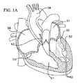
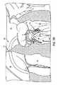
図1A〜図1Bを概して参照すると、天然僧帽弁50が、ヒトの心臓の左心房51から左心室52への血流を制御し、同様に三尖弁59が、右心房56と右心室61との間の血流を制御する。僧帽弁は、他の天然心臓弁とは異なる解剖学的構造を有する。僧帽弁は、僧帽弁口を囲む天然弁組織から構成された弁輪と、弁輪から左心室内へと下方に延在する一対の弁尖または弁葉とを備える。僧帽弁輪は、「D字」形、楕円形、または長軸および短軸を有する他の非円形の断面形状を形成し得る。前尖が、弁の後尖よりも大きいことにより、これらが共に閉じられた場合に弁葉の当接し合う自由エッジ同士の間に略「C字」形状境界部が形成され得る。 Referring generally to FIGS. 1A-1B, a
適切に動作する場合に、僧帽弁の前尖54および後尖53は、左心房51から左心室52に血液を流し得る一方向弁として共に機能する。左心房が肺静脈から酸素を多く含む血液を受領した後に、左心房の筋は収縮し、左心室は弛緩し(「心室拡張期」または「拡張期」とも呼ばれる)、左心房内に収集される酸素を多く含んだ血液は左心室内に流れる。次いで、左心房の筋が弛緩し、左心室の筋が収縮し(「心室収縮期」または「収縮期」とも呼ばれる)、それにより左心室52から大動脈弁63および大動脈58を通り身体の残りの部分へと酸素を多く含む血液を移動させる。心室収縮期中に左心室内の血圧が上昇することにより、僧帽弁の2つの弁葉が合わさるように付勢され、それにより血液が左心房内に逆流することができなくなるように一方向僧帽弁が閉じられる。これらの2つの弁葉がこの圧力下において逸脱し、心室収縮期中に僧帽弁輪を通り左心房に向かって折り返されるのを防止または阻止するために、腱索と呼ばれる複数の線維索62が、左心室中の乳頭筋に対して弁葉を繋留する。腱索62は、図1Aの心臓断面図および図1Bの僧帽弁の上面図の両方において概略的に図示される。 When operated properly, the
僧帽弁の適切な機能に関する問題は、あるタイプの心臓弁膜症である。心臓血管症は、三尖弁を含む他の心臓弁にも影響を及ぼし得る。心臓弁膜症の一般的形態は、逆流としても知られる弁リークであり、これは、僧帽弁および三尖弁の両方を含む様々な心臓弁において生じ得る。僧帽弁逆流は、天然僧帽弁が適切に閉じることができず、血液が心室収縮期中に左心室から左心房内へと逆流する場合に生じる。僧帽弁逆流は、弁葉逸脱、乳頭筋機能不全、腱索の問題、および/または左心室の拡張の結果として生じる僧帽弁輪の伸長などの種々の原因を有し得る。僧帽弁逆流に加えて、僧帽弁の狭隘化すなわち僧帽弁狭窄が、心臓弁膜症の別の例である。三尖弁逆流では、三尖弁は、適切に閉じることができず、血液は、右心室から右心房内に逆流する。 A problem with the proper functioning of the mitral valve is a type of valvular heart disease. Cardiovascular disease can also affect other heart valves, including the tricuspid valve. A common form of valvular heart disease is valve leak, also known as regurgitation, which can occur in various heart valves, including both mitral and tricuspid valves. Mitral regurgitation occurs when the native mitral valve fails to close properly and blood regurgitates from the left ventricle into the left atrium during ventricular systole. Mitral regurgitation can have a variety of causes, such as leaflet prolapse, papillary muscle dysfunction, chordae problems, and / or mitral valve annulus extension as a result of left ventricular dilation. In addition to mitral regurgitation, mitral valve narrowing or mitral stenosis is another example of valvular heart disease. In tricuspid regurgitation, the tricuspid valve cannot close properly and blood regurgitates from the right ventricle into the right atrium.
僧帽弁および三尖弁と同様に、大動脈弁は、大動脈弁狭窄または大動脈弁不全症などの合併症を同様に被りやすい。大動脈心疾患を治療するための1つの方法は、天然大動脈弁内に植え込まれた人工弁の使用を含む。これらの人工弁は、様々な経カテーテル技術を含む様々な技術を利用して植え込まれ得る。経カテーテル心臓弁(THV)が、可撓性および/または操縦可能カテーテルの端部部分上に圧着状態に取り付けられ、心臓に続く血管を経由して心臓内の植込み部位まで前進され、次いで例えばTHVが取り付けられたバルーンを膨張させることなどにより機能サイズまで拡張され得る。代替的には、自己拡張型THVが、送達カテーテルのシース内において径方向圧縮状態で保持されることが可能であり、この場合にTHVは、シースから展開されることが可能であり、これによりTHVは機能状態へと拡張され得る。かかる送達カテーテルおよび植込み技術は、一般的に大動脈弁における植込みまたは使用向けにより多く展開されるが、独特な解剖学的構造体および他の弁の問題には対応していない。 Like the mitral and tricuspid valves, the aortic valve is equally susceptible to complications such as aortic stenosis or aortic insufficiency. One method for treating aortic heart disease involves the use of a prosthetic valve implanted within a native aortic valve. These prosthetic valves can be implanted using various techniques, including various transcatheter techniques. A transcatheter heart valve (THV) is crimped on the end portion of a flexible and / or steerable catheter, advanced through the blood vessels following the heart to an implantation site in the heart, and then, for example, the THV Can be expanded to a functional size, such as by inflating a balloon attached. Alternatively, a self-expanding THV can be held in a radially compressed state within the sheath of the delivery catheter, where the THV can be deployed from the sheath, THV can be extended to a functional state. Such delivery catheters and implantation techniques are generally more deployed for implantation or use in aortic valves, but do not address unique anatomical structures and other valve issues.
この概要は、いくつかの例を提示するように意図され、いかなる点においても本発明の範囲を限定するようには意図されない。例えば、本概要の一例に含まれるいかなる特徴も、特許請求の範囲においてそれらの特徴が明示的に列挙されない限りは、特許請求の範囲の要件とはならない。また、説明される特徴は、様々な様式で組み合わされ得る。本開示内の他の箇所で説明されるような様々な特徴およびステップは、ここに概説される例に含まれてもよい。 This summary is intended to provide some examples and is not intended to limit the scope of the invention in any way. For example, any features included in one example of this summary are not required to be claimed unless such features are explicitly recited in the claims. Also, the described features may be combined in various ways. Various features and steps as described elsewhere in this disclosure may be included in the examples outlined herein.
ツールおよび方法が、僧帽弁位置および三尖弁位置における使用のために種々のタイプの弁(例えば大動脈弁置換用にまたは他の箇所向けに設計されたものなど)を適合化することを目的とすることを含め、僧帽弁置換および三尖弁置換向けに提供される。僧帽位置または三尖位置にてこれらの他の人工弁を適合化させる1つの方法は、天然弁輪により適切に形状設定された植込み部位を形成するアンカーまたは他のドッキングデバイス/ステーション内に人工弁を展開することである。本明細書におけるアンカーまたは他のドッキングデバイス/ステーションは、人工弁がよりしっかりと植え込まれるのを可能にすると共に、さらに植込み後の弁の周囲における漏れを軽減または解消する。 The tools and methods aim to adapt various types of valves (eg, designed for aortic valve replacement or elsewhere) for use in mitral and tricuspid valve positions Provided for mitral valve replacement and tricuspid valve replacement. One method of adapting these other prosthetic valves in a mitral or tricuspid position is to create a prosthesis in an anchor or other docking device / station that forms a properly shaped implantation site with a natural annulus. Is to deploy the valve. The anchors or other docking devices / stations herein allow the prosthetic valve to be implanted more securely, and also reduce or eliminate leakage around the valve after implantation.
本明細書において使用され得る1つのタイプのアンカーまたはアンカリングデバイスは、円筒形状人工弁用の円形ドッキング部位または円筒状ドッキング部位を提供するコイルアンカーまたはらせん形状アンカーである。本明細書において使用され得る1つのタイプのアンカーまたはアンカリングデバイスは、円筒形状人工弁用の円形ドッキング部位または円筒状ドッキング部位を提供するコイル領域および/またはらせん形状領域を備える。このようにすることで、任意には、大動脈位置向けに展開された既存の弁インプラントが、おそらく何らかの修正を伴って、かかるアンカーまたはアンカリングデバイスと共に僧帽位置などの別の弁位置に植え込まれることが可能となる。かかるアンカーまたはアンカリングデバイスは、これらの部位に人工弁をより確実にアンカリングするために、三尖弁などの心臓の他の天然弁においても使用され得る。 One type of anchor or anchoring device that may be used herein is a coil or helical anchor that provides a circular or cylindrical docking site for a cylindrical prosthetic valve. One type of anchor or anchoring device that may be used herein comprises a coiled and / or helically shaped region that provides a circular or cylindrical docking site for a cylindrical prosthetic valve. In this way, optionally, an existing valve implant deployed for the aortic position is implanted, possibly with some modifications, into another valve position, such as a mitral position, with such an anchor or anchoring device. It is possible to be. Such anchors or anchoring devices can also be used in other natural valves of the heart, such as tricuspid valves, to more reliably anchor prosthetic valves at these sites.
本明細書では、ヒトの心臓の天然僧帽弁領域、天然大動脈弁領域、天然三尖弁領域、または天然肺動脈弁領域の中の1つに人工デバイスを送達することを支援するための展開ツールと、かかる展開ツールを使用するための方法との実施形態が説明される。開示される展開ツールは、人工心臓弁が植え込まれ得る基礎支持構造体を提供するために、植込み部位にてらせん状アンカリングデバイスまたは複数の巻線またはコイルを有するアンカリングデバイスなどのアンカリングデバイス(例えばプロテーゼドッキングデバイス、人工弁ドッキングデバイス等)を展開するために使用され得る。展開ツールは、アンカーまたはアンカリングデバイスが植え込まれる際にこれらのアンカーまたはアンカリングデバイスの位置決めを案内するための遠位屈曲セクションを備え得る。 SUMMARY A deployment tool is described herein to assist in delivering a prosthetic device to one of a native mitral valve region, a native aortic valve region, a native tricuspid valve region, or a native pulmonary valve region of a human heart. And embodiments for using such a deployment tool are described. The disclosed deployment tools provide anchoring, such as a helical anchoring device or an anchoring device having multiple windings or coils at the implantation site to provide a basic support structure into which the prosthetic heart valve can be implanted. It can be used to deploy a device (eg, a prosthetic docking device, an artificial valve docking device, etc.). The deployment tool can include a distal bend section to guide the positioning of the anchors or anchoring devices as they are implanted.
一実施形態では、患者の心臓の天然弁輪までアンカリングデバイスを送達するための送達カテーテルであって、アンカリングデバイスが天然弁輪にてプロテーゼ(例えば人工心臓弁)を固定するように構成された、送達カテーテルが、可撓性チューブ、第1のプルワイヤ、および第2のプルワイヤを備える。可撓性チューブは、第1の端部を有する近位部分と、第2の端部を有する遠位部分と、第1の端部と第2の端部との間に延在するボアとを備える。ボアは、アンカリングデバイスを通過させるようにサイズ設定される。遠位部分は、第1の曲げセクションおよび第2の曲げセクションを備える。送達カテーテルは、第1のプルワイヤおよび第2のプルワイヤの作動により、可撓性チューブが第1の構成から第2の構成へと動かされるように構成され得る。可撓性チューブが第2の構成にある場合に、第1の曲げセクションは第1の湾曲部分を形成し、第2の曲げセクションは略円形かつ略平坦状の部分を形成し得る。 In one embodiment, a delivery catheter for delivering an anchoring device to a natural annulus of a patient's heart, wherein the anchoring device is configured to secure a prosthesis (eg, a prosthetic heart valve) at the natural annulus. In addition, a delivery catheter includes a flexible tube, a first pull wire, and a second pull wire. The flexible tube has a proximal portion having a first end, a distal portion having a second end, and a bore extending between the first and second ends. Is provided. The bore is sized to pass through an anchoring device. The distal portion includes a first bending section and a second bending section. The delivery catheter may be configured such that actuation of the first pull wire and the second pull wire causes the flexible tube to be moved from the first configuration to the second configuration. When the flexible tube is in the second configuration, the first bent section may form a first curved portion and the second bent section may form a substantially circular and substantially flat portion.
送達カテーテルは、第1のリングおよび第2のリングを備え得る。第1のリングは第1の作動ポイントに配設され、第1のプルワイヤは第1のリングに対して装着され得る。第2のリングは第2の作動ポイントに配設され、第2のプルワイヤは第2のリングに対して装着され得る。第1のプルワイヤは、約90度だけなど、約65度〜約115度の間だけ第2のプルワイヤから周方向にオフセットされ得る。 The delivery catheter may include a first ring and a second ring. A first ring is disposed at a first actuation point, and a first pull wire may be attached to the first ring. A second ring is disposed at a second actuation point, and a second pull wire can be attached to the second ring. The first pull wire may be circumferentially offset from the second pull wire by between about 65 degrees and about 115 degrees, such as by about 90 degrees.
カテーテルは、近位部分と第2のリングとの間に配設された第3のリングを備え得る。第1のスパインが、第1のリングと第2のリングとの間に配設され得る。第2のスパインが、第2のリングと第3のリングとの間に配設され得る。第1のスパインは、可撓性チューブが第2の構成へと動かされる場合に、第1のリングと第2のリングとの間における圧縮動を制限するように構成され得る。第2のスパインは、可撓性チューブが第2の構成へと動かされる場合に、第2のリングと第3のリングとの間における第1のプルワイヤによる屈曲を制限するように構成され得る。第1のスパインのショアD硬度と第2のスパインのショアD硬度との比率は、約1.5:1〜約6:1の間であり得る。 The catheter may include a third ring disposed between the proximal portion and the second ring. A first spine may be disposed between the first ring and the second ring. A second spine may be disposed between the second ring and the third ring. The first spine may be configured to limit compression movement between the first ring and the second ring when the flexible tube is moved to the second configuration. The second spine may be configured to limit bending by the first pull wire between the second and third rings when the flexible tube is moved to the second configuration. The ratio of the Shore D hardness of the first spine to the Shore D hardness of the second spine may be between about 1.5: 1 to about 6: 1.
可撓性端部部分が、円形または湾曲平坦部分の主要部分に対して角度をつけられるように構成され得る。例えば、可撓性端部分と主要部分との間の垂直変位は、約2mm〜約10mmの間であり得る。 The flexible end portion may be configured to be angled with respect to the main portion of the circular or curved flat portion. For example, the vertical displacement between the flexible end portion and the main portion can be between about 2 mm to about 10 mm.
カテーテルは、第1のプルワイヤの少なくとも一部分の周囲に延在する第1のコイル状スリーブ、および/または第2のプルワイヤの少なくとも一部分の周囲に延在する第2のコイル状スリーブとをさらに備え得る。 The catheter may further comprise a first coiled sleeve extending around at least a portion of the first pull wire, and / or a second coiled sleeve extending around at least a portion of the second pull wire. .
送達カテーテルが、患者の心臓の天然弁までアンカリングデバイスを送達するために送達カテーテルを使用する方法において、心臓まで(例えば心房などの心臓の心腔内に)前進され得る。第1の湾曲部分が、送達カテーテルの第1の曲げセクション中に形成され、略円形または湾曲状の(例えば円形形状を模倣するもしくは円形形状と同様となるように湾曲された)および略平坦状の部分が、送達カテーテルの第2の曲げセクション中に形成され得る。略円形部分の端部に位置する遠位開口が、天然弁の交連の方向に位置決めされ得る。アンカリングデバイスは、カテーテルを通り天然弁まで送達される。任意には、送達カテーテルの遠位開口の高さまたは角度が、送達カテーテルの少なくとも一部分が天然弁の弁輪の平面または天然弁輪を通る平面に対して実質的に平行になるように調節され得る。 The delivery catheter can be advanced to the heart (eg, into a chamber of the heart such as an atrium) in a manner that uses the delivery catheter to deliver the anchoring device to a native valve of the patient's heart. A first curved portion is formed in the first bent section of the delivery catheter and is generally circular or curved (eg, imitating a circular shape or curved to be similar to a circular shape) and generally flat. May be formed in the second bent section of the delivery catheter. A distal opening located at the end of the generally circular portion may be positioned in the direction of the commissure of the natural valve. The anchoring device is delivered through the catheter to the natural valve. Optionally, the height or angle of the distal opening of the delivery catheter is adjusted so that at least a portion of the delivery catheter is substantially parallel to the plane of the annulus of the native valve or the plane passing through the native annulus. obtain.
別の実施形態では、患者の心臓の天然弁輪までアンカリングデバイスを送達するために送達カテーテルを使用する方法であって、アンカリングデバイスが天然弁輪にてプロテーゼを固定するように構成された、方法が、心臓まで(例えば心房などの心臓の心腔内に)送達カテーテルを前進させるステップと、送達カテーテルの遠位開口が天然弁の交連の付近に位置決めされるように、天然弁輪の周囲に少なくとも部分的に送達カテーテルを屈曲させるステップと、送達カテーテルの少なくとも一部分が天然弁輪を含む平面に対して実質的に平行になるように、送達カテーテルの延長部の高さまたは角度の少なくとも一方を調節するステップとを含む。天然弁が僧帽弁である場合には、送達カテーテルは、心房中隔を経由して右心房から左心房内に前進される。 In another embodiment, a method of using a delivery catheter to deliver an anchoring device to a natural annulus of a patient's heart, wherein the anchoring device is configured to secure a prosthesis at the natural annulus. Advancing the delivery catheter to the heart (e.g., into the heart chamber of the heart such as the atrium), and positioning the natural annulus such that the distal opening of the delivery catheter is positioned near the commissure of the natural valve. At least partially bending the delivery catheter around the periphery and at least a height or angle of the extension of the delivery catheter such that at least a portion of the delivery catheter is substantially parallel to a plane containing the native annulus. Adjusting one. If the native valve is a mitral valve, the delivery catheter is advanced from the right atrium into the left atrium via the atrial septum.
ここに概説されたシステムおよびカテーテルは、本開示の他の箇所において説明される特徴、構成要素、要素等のいずれかをさらに備えることが可能であり、ここに概説された方法は、本開示の他の箇所において説明されるステップのいずれかをさらに含むことが可能である。 The systems and catheters outlined herein can further include any of the features, components, elements, etc. described elsewhere in this disclosure, and the methods outlined herein are compatible with the methods disclosed herein. It can further include any of the steps described elsewhere.
前述および他の本発明の目的、特徴、および利点が、添付の図面を利用して以下の詳細な説明からさらに明らかになろう。 The foregoing and other objects, features, and advantages of the invention will become more apparent from the following detailed description, taken in conjunction with the accompanying drawings.
特定の実施形態を説明し示す以下の説明および添付の図面は、本開示の様々な態様および特徴のために使用され得るシステム、デバイス、装置、構成要素、方法等の複数の可能な構成を非限定的な様式で実例により示すために行われる。一例としては、本明細書では、僧帽弁手技に関連し得る様々なシステム、デバイス/装置、構成要素、方法等が説明される。しかし、提示される具体例は、限定的なものとしては意図されず、例えばシステム、デバイス/装置、構成要素、方法等は、僧帽弁以外の他の弁(例えば三尖弁)における使用に対しても適合化され得る。 The following description and accompanying drawings that describe and illustrate certain embodiments illustrate several possible configurations of systems, devices, apparatus, components, methods, etc., that may be used for various aspects and features of the present disclosure. This is done by way of illustration in a limited manner. By way of example, various systems, devices / apparatuses, components, methods, and the like are described herein that may be associated with a mitral valve procedure. However, the examples presented are not intended to be limiting, for example, systems, devices / apparatus, components, methods, etc. may be used for use with other valves than the mitral valve (eg, the tricuspid valve). Can also be adapted.
本明細書においては、ヒトの心臓の天然僧帽弁領域、大動脈弁領域、三尖弁領域、または肺動脈弁領域の中の1つにおける人工デバイス(例えば人工弁)の植込みを容易にするように意図された展開ツールと、この展開ツールを使用するための方法との実施形態が説明される。人工デバイスまたは人工弁は、拡張可能な経カテーテル心臓弁(「THV」)(例えばバルーン拡張可能THV、自己拡張型THV、および/または機械的拡張型THV)であることが可能である。展開ツールは、天然弁領域に人工デバイスまたは人工弁(例えばTHV)を固定するためにより安定的なドッキング部位を与えるアンカリングデバイス(時としてドッキングデバイス、ドッキングステーション、または同様の用語で呼ばれる)を展開するために使用され得る。これらの展開ツールは、アンカリングデバイスおよびそれにアンカリングされた任意のプロテーゼ(例えば人工デバイスまたは人工心臓弁)が、植込み後に適切に機能するように、かかるアンカリングデバイス(例えばプロテーゼアンカリングデバイス、人工弁アンカリングデバイス等)をより正確に配置するために使用され得る。 As used herein, to facilitate implantation of a prosthetic device (eg, a prosthetic valve) in one of the native mitral, aortic, tricuspid, or pulmonary valve regions of the human heart. Embodiments of the intended deployment tool and method for using the deployment tool are described. The prosthetic device or valve can be an expandable transcatheter heart valve ("THV") (eg, a balloon expandable THV, a self-expanding THV, and / or a mechanically expandable THV). The deployment tool deploys an artificial device or an anchoring device (sometimes referred to as a docking device, docking station, or similar terminology) that provides a more stable docking site for securing a prosthetic valve (eg, a THV) to the native valve area. Can be used to These deployment tools can be used to ensure that the anchoring device and any prostheses anchored thereto (eg, a prosthetic device or prosthetic heart valve) function properly after implantation, such anchoring devices (eg, prosthetic anchoring devices, artificial prostheses). (Such as a valve anchoring device).
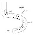
1つのかかるアンカリングデバイスの一例が、図2Aに示される。本明細書で使用され得るアンカリングデバイスの他の例は、特許文献1、特許文献2、および特許文献3に示され、これらの特許出願はそれぞれ、参照によりそれらの全体が本明細書に組み込まれる。本明細書におけるアンカリングデバイスは、コイル状もしくはらせん状であることが可能であり、あるいは1つまたは複数のコイル状領域もしくはらせん状領域を備えることが可能である。アンカリングデバイス1が、2つの上方コイル10a、10bおよび2つの下方コイル12a、12bを備えるものとして図2Aに示される。代替的な実施形態では、アンカリングデバイス1は、任意の適切な個数の上方コイルおよび下方コイルを備え得る。例えば、アンカリングデバイス1は、1つの上方コイル、2つ以上の上方コイル、3つ以上の上方コイル、4つ以上の上方コイル、5つ以上の上方コイル等を備えることが可能である。さらに、アンカリングデバイス1は、1つの下方コイル、2つ以上の下方コイル、3つ以上の下方コイル、4つ以上の下方コイル、5つ以上の下方コイル等を備えることが可能である。様々な実施形態において、アンカリングデバイス1は、有する下方コイルと同一個数の上方コイルを有することが可能である。他の実施形態では、アンカリングデバイス1は、下方コイルに比べてより多数またはより少数の上方コイルを有することが可能である。 One example of one such anchoring device is shown in FIG. 2A. Other examples of anchoring devices that may be used herein are shown in U.S. Pat. Nos. 6,059,009, 6,069,086, and 6,098,098, each of which is incorporated herein by reference in its entirety. It is. An anchoring device herein can be coiled or helical, or can include one or more coiled or helical regions. The
アンカリングデバイスが、変動直径または同一直径のコイル/巻線、変動間隙サイズで離間されたまたは無間隙のコイル/巻線、およびさらに大きくまたは小さくなるようにテーパ状をなす、拡張する、またはフレア状をなすコイル/巻線を備えることが可能である。これらのコイル/巻線は、人工弁がアンカリングデバイス1内に配置されたまたは拡張された場合に、径方向外方に伸長することも可能である点に留意されたい。 An anchoring device wherein coils / windings of varying or equal diameter, spaced / no gap coils / windings of varying gap size, and taper, expand, or flare to be larger or smaller. It is possible to provide a coil / winding in the form. Note that these coils / windings can also extend radially outward when the prosthetic valve is placed or expanded in the
図2Aに図示する実施形態では、上方コイル10a、10bは、下方コイル12a、12bとほぼ同一サイズであることが可能であり、または下方コイル12a、12bよりも若干小さい直径を有することが可能である。1つまたは複数の下方端部コイル/巻線(例えば完全端部コイル/巻線または部分的端部コイル/巻線)が、他のコイルよりも大きな直径または大きな曲率半径を有し、例えば弁葉および/または任意の腱索を包囲し捕えるためなどに、弁葉および/または任意の腱索の外部および周囲にコイルの端部を案内するのを補助するための包囲コイル/巻線として機能することが可能である。1つまたは複数のより大きな直径またはより大きな半径の下方コイルまたは包囲コイルは、天然弁輪とのより容易な係合と、挿入中の天然弁解剖学的構造体の周囲へのより容易な誘導とを可能にする。 In the embodiment illustrated in FIG. 2A, the
いくつかの実施形態では、1つまたは複数の上方コイル/巻線(例えば完全コイル/巻線または部分コイル/巻線)が、より大きいまたはより大きな直径(もしくは曲率半径)を有し、人工弁が展開される前に定位置にコイルを保持するのを補助するための安定化コイル(例えば心臓の心房内の)として機能することが可能である。いくつかの実施形態では、この1つまたは複数の上方コイル/巻線は、心房コイル/巻線であることが可能であり、心室内のコイルよりも大きな直径を有することにより、例えば安定化のために心房壁に係合するように構成された安定化コイル/巻線として機能することが可能である。 In some embodiments, one or more of the upper coils / windings (eg, full or partial coils / windings) have a larger or larger diameter (or radius of curvature) and the prosthetic valve Can function as a stabilizing coil (eg, in the atrium of the heart) to help hold the coil in place before it is deployed. In some embodiments, the one or more upper coils / windings can be atrial coils / windings and have a larger diameter than the coils in the ventricle, eg, for stabilization. It can function as a stabilizing coil / winding configured to engage the atrial wall.
コイルの中のいくつかが、機能コイル(例えば安定化コイル/巻線と包囲コイル/巻線との間のコイル/巻線)であることが可能であり、人工弁は、この機能コイル内で展開され、機能コイルと人工弁との間の力が、これらを相互に定位置に保持するのを補助する。アンカリングデバイスおよび人工弁は、アンカリングデバイスおよび人工弁が定位置によりしっかりと保持されるように、間に(例えばアンカリングデバイスの機能コイルと人工弁の外方表面との間に)天然組織(例えば弁葉および/または腱)を挟み得る。 Some of the coils can be functional coils (e.g., coils / windings between the stabilizing coil / winding and the surrounding coil / winding) where the prosthetic valve is within the functional coil. When deployed, the forces between the functional coil and the prosthetic valve help hold them in place relative to each other. The anchoring device and the prosthetic valve are placed between the native tissue (eg, between the functional coil of the anchoring device and the outer surface of the prosthetic valve) such that the anchoring device and the prosthetic valve are more securely held in place. (Eg, leaflets and / or tendons).
図9I〜図9Uに示すアンカリングデバイスと同一または同様であり得る一実施形態では、アンカリングデバイスが、1つの大きな上方コイル/巻線または安定化コイル/巻線、1つの下方端部コイル/巻線または包囲コイル/巻線、および複数の機能コイル/巻線(例えば2つ、3つ、4つ、5つ、またはそれ以上の個数の機能コイル/巻線)を有する。 In one embodiment, which may be the same or similar to the anchoring device shown in FIGS. 9I-9U, the anchoring device comprises one large upper coil / winding or stabilizing coil / winding, one lower end coil / It has a winding or surrounding coil / winding and a plurality of functional coils / windings (eg, two, three, four, five or more functional coils / windings).
僧帽位置にて使用される場合に、アンカリングデバイスは、例えば図2Cに示すように、1つまたは複数の上方コイル/巻線(例えば上方コイル10a、10b)が天然弁(例えば僧帽弁50または三尖弁)の弁輪の上方、すなわち心房側に位置するように、および下方コイル12a、12bが天然弁の弁輪の下方、すなわち心室側に位置するように植え込まれ得る。この構成では、僧帽弁葉53、54は、上方コイル10a、10bと下方コイル12a、12bとの間に捕捉され得る。植え込まれた場合に、本明細書における様々なアンカリングデバイスは、人工弁を定位置に固定し、心臓の動作による移動を回避するための、しっかりした支持構造部を提供し得る。 When used in a mitral position, the anchoring device may include one or more upper coils / windings (eg,
図2Bは、経中隔技術を利用して天然僧帽弁輪50にアンカリングデバイスを設置するための一般的な送達デバイス2を示す。同一または同様の送達デバイス2は、左心房内へと中隔を横断するために右心房から出る必要性を伴うことなく、三尖弁にてアンカリングデバイスを送達するために使用され得る。送達デバイス2は、外方シースまたはガイドシース20と、可撓性送達カテーテル24とを備える。シース20は、送達カテーテル24および様々な他の構成要素(例えばアンカリングデバイス、人工心臓弁等)が通過することの可能な長尺中空チューブの形状のシャフトを有し、したがって構成要素は、患者の心臓5内に導入されることが可能となる。シース20は、シースが心臓5を通過し左心房51に進入するために必要とされる様々な角度で屈曲され得るように操縦可能であることが可能である。シース20内にある場合に、送達カテーテル24は、比較的直線状のまたは直線化された構成にあり(以下でさらに詳細に論じられる屈曲構成と比較して)、例えば送達カテーテル24は、シース20の構成または形状に対応する構成または形状においてシース20内に保持される。 FIG. 2B shows a
シース20と同様に、送達カテーテル24は、長尺中空チューブの形状を有するシャフトを有する。しかし、送達カテーテル24は、シース20内において軸方向に摺動し得るように、シース20よりも小さな直径を有する。一方で、送達カテーテル24は、アンカリングデバイス1などのアンカリングデバイスを収容および展開するのに十分な大きさである。 Like the
また、可撓性送達カテーテル24は、可撓性遠位セクション25を有する。遠位セクション25は、アンカリングデバイス1のより正確な配置を可能にする構成へと屈曲されることが可能であり、一般的には遠位セクション25がかかる構成に屈曲され保持されるのを可能にする強固な設計を有するべきである。例えば、図2Bに示すように、可撓性遠位セクション25は、遠位セクション25が僧帽弁50の心室側においてアンカリングデバイス1からの押出しを支援するように湾曲状となる湾曲構成へと屈曲されることが可能であり、それによりアンカリングデバイス1の下方コイル(例えば機能コイルおよび/または包囲コイル)は、天然弁の弁輪の下方に適切に設置されることが可能となる。また、可撓性遠位セクション25は、アンカリングデバイスの上方コイル(例えば安定化コイル/巻線または上方コイル10a、10b)が天然弁の弁輪の心房側で正確に展開され得るように、同一のまたは異なる湾曲構成へと屈曲され得る。例えば、可撓性遠位セクション25は、下方コイル12a、12bを設置するために使用されるのと同一である、上方コイル10a、10bを設置するための構成を有し得る。他の実施形態では、可撓性遠位セクション25は、下方コイル12a、12bを設置するための1つの構成と、上方コイル10a、10bを設置するための別の構成とを有し得る。例えば、可撓性遠位セクション25は、天然弁の弁輪の心房側において上方コイル10a、10bを放出および位置決めするために下方コイル12a、12bを放出するために、上述の位置から後退方向へと軸方向に並進移動され得る。 The
使用時に、僧帽弁にアクセスするために経中隔送達方法を利用する場合に、シース20は、大腿静脈を通り、下大静脈57を通り、右心房56内へと挿入され得る。代替的には、シース20は、頸静脈または鎖骨下静脈または他の上方血管位置に挿通され、上大静脈を通り右心房内へと進み得る。次いで、図2Bで分かるように、心房中隔55が穿孔され(例えば卵円窩にて)、シース20は左心房51内に進められる(三尖弁手技では、中隔55を穿孔または横断することは不要である)。シース20は、遠位端部部分21を有し、この遠位端部部分21は、心臓の所望の内腔(例えば左心房51)内へのシース20の操縦を容易化するための操縦可能なまたは事前湾曲された遠位端部部分であり得る。 In use, if utilizing the transseptal delivery method to access the mitral valve, the
僧帽弁手技では、シース20が左心房51内の定位置にある状態において、送達カテーテル24は、送達カテーテル24の遠位セクション25が左心房51内にやはり位置するように、シース20の遠位端部21から前進される。この位置において、送達カテーテル24の遠位セクション25は、アンカリングデバイス1が僧帽弁50の弁輪に設置されることを可能にする1つまたは複数の湾曲構成または作動構成へと屈曲または湾曲され得る。次いで、アンカリングデバイス1は、送達カテーテル24を通り前進され、僧帽弁50に設置され得る。アンカリングデバイス1は、植込み用の送達カテーテル24を通してアンカリングデバイス1を前進させるまたは押すプッシャに対して装着され得る。プッシャは、送達カテーテル24にアンカリングデバイス1を押し通すために十分な強度および物理的特徴を有するワイヤまたはチューブであることが可能である。いくつかの実施形態では、プッシャは、他の構造体の中でもとりわけばねもしくはコイル(例えば以下の図17A〜図18Cの可撓性チューブ87、97を参照)、チューブ延長部、編組チューブ、またはレーザ切断ハイポチューブから作製されるかまたはそれらを備え得る。いくつかの実施形態では、プッシャは、コーティングにより外部および/または内部を覆われることが可能であり、例えばPTFEによりライニングされた内部ルーメンを有することにより、ライン(例えば縫合糸)がこのライニングされたルーメンを通して外傷を与えることなく作動されることを可能にし得る。上記のように、いくつかの実施形態では、プッシャが左心室内のアンカリングデバイス1の心室コイルを押したまたは適切に位置決めした後に、遠位セクション25は、例えば左心室内のアンカリングデバイス1の心室コイルの位置を維持または保持しつつ、左心房内にアンカリングデバイス1の心房コイルを放出するように後退方向へと軸方向に並進移動され得る。 In a mitral valve procedure, with the
アンカリングデバイス1が設置されると、送達カテーテル24は、送達カテーテル24がシース20を通して戻され得るように可撓性遠位セクション25の湾曲を直線化または軽減することによって除去され得る。送達カテーテル24が除去された状態で、次いで、例えば人工経カテーテル心臓弁(THV)60などの人工弁が、例えば図2Cに示すように、例えばシース20に通され、アンカリングデバイス1内に固定され得る。THV60がアンカリングデバイス1内に固定されると、次いでシース20は、THV60用の任意の他の送達装置と共に患者の体内から除去され、患者の中隔55および右大腿静脈中の開口が、閉じられ得る。他の実施形態では、アンカリングデバイス1が植え込まれた後に、完全に異なるシースまたは異なる送達デバイスが、THV60を送達するために別個に使用され得る。例えば、ガイドワイヤが、シース20を通り導入され得るか、またはシース20が、除去され、ガイドワイヤが、別個の送達カテーテルを使用して同一のアクセスポイントを経由して天然僧帽弁を貫通し左心室内へと前進され得る。一方で、アンカリングデバイスは、この実施形態においては経中隔で植え込まれるが、経中隔植込みに限定されるものではなく、THV60の送達は、経中隔送達(またはより一般的には、アンカリングデバイスの送達と同一のアクセスポイントを経由した)に限定されない。さらに他の実施形態では、アンカリングデバイス1の経中隔送達後に、様々な他のアクセスポイントの中の任意のものが、THV60を植え込む(例えば経心尖、経心房、または経大腿動脈などにより)ために使用され得る。 Once the
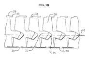
図3Aは、送達カテーテル24内で使用され得る一例の遠位セクション25の斜視図を示す。この遠位セクションは、2つの両端部と、これらの2つの端部間に延在する2つの両側部26および27、頂部28、ならびに底部29を備える。これらは、説明および理解の容易化を目的として符号を付されているが、遠位セクション25の配向を限定するようには意図されない。図3Aの遠位セクション25は、複数のリンク38を備え得る略円筒状の中空チューブを形成する。各リンク38が、円筒状セグメントの形状を有し、各リンク38が、遠位セクション25の円筒状チューブ形状を形成するように隣接するリンク38に整列され連結される。遠位セクション25は、この実施形態では円筒状であるが、卵形遠位セクションなどの他の形状もまた可能である。遠位セクション25の各リンク38が、頂部28よりも底部29においてより大きな幅を有することが可能であり、これによりリンク38は、図3Bにおいて最もよく分かるように側方から見た場合に底辺に2つの鋭角を有する台形の全体形状を与えられる。各リンク38の底部は、リンク38同士の相互に対するさらなる曲げを可能にするためのスリット39を有し得る。 FIG. 3A shows a perspective view of an example
遠位セクション25は、側歯31、32および上歯33の両方を組み込むハイブリッド屈曲セクションを形成するダブルガイドパターンを備え得る。この趣旨で、各リンク38は、リンク38の両側の2つの側歯31、32と、上歯33とを備え得る。図3Aにおいて最もよく分かるように、遠位セクション25に関して、リンク38の2列の側歯31、32が遠位セクション25の側部26、27の長さにわたりそれぞれ延在し、上歯33は、頂部28において遠位セクション25の長さにわたり延在し得る。この図示する実施形態では、側歯31、32および上歯33の列が、遠位セクション25の長さに沿って直線状に延在するのが示されるが、他の実施形態は異なる構成を有することが可能である。例えば、いくつかの実施形態では、側歯31、32および上歯33の列は、例えば図4に示されるように、遠位セクション25が作動された場合に遠位セクション25に特定の屈曲形状をもたらすように、遠位セクション25のチューブの周囲においてらせん状であることが可能である。いくつかの実施形態では、側歯31、32は、遠位セクション25の両側部26、27における相似屈曲を可能にするように相互に鏡像を成すことが可能である。他の実施形態では、側歯31、32は、相互比較においてそれぞれ異なる形状および/またはサイズを有し得る。これらの歯31、32、33は、アンカリングデバイスを送達する間に遠位セクション25が曲げ構成へと動くことを可能にする任意の他の適切な形状および/またはサイズをとることが可能である。これらの歯31、32、33はいずれも、図示する実施形態では右向きの歯である(例えば図3Bに示す図において右向きである)が、他の実施形態では、例えばこれらの歯は、左向きの歯であることが可能であり(例えば図4を参照)、または上歯および側歯が、それぞれ異なる方向を向くことが可能である。 The
各側歯31、32および各上歯33に隣接して、対応する側部スロットまたは側部溝34、35と、上部スロットまたは上部溝36とが、隣接するリンク38上にそれぞれ存在する。各スロット34、35、36は、隣接する側歯31、32または上歯33に対して相補的な形状を有し得る。遠位セクション25が直線構成にある場合に、側歯31、32は、側部スロット34、35内に部分的に挿入され、上歯33は、ある間隙をおいて隣接する上部スロット36から離間される。この直線構成において側歯31、32を側部スロット34、35内に部分的におくことにより、送達カテーテル24の遠位セクション25が完全には曲げられない場合に、遠位セクション25に対する追加的なトルク抵抗が与えられる。しかし、他の実施形態では、側歯31、32は、遠位セクション25がこの直線構成にある場合に側部スロット34、35内に部分的に位置決めされなくてもよい。 Adjacent to each
遠位セクション25が屈曲されると、各側歯31、32は、対応する側部スロット34、35内へとさらに移動し、各上歯33は、対応する上部スロット36のより近くにおよび次いでその中に移動する。上歯33および上部スロット36の追加により、遠位セクション25が完全曲げ構成にある場合におけるトルク性およびトルク抵抗の向上が遠位セクション25に対してもたらされる。さらに、側歯31、32および上歯33の両方を有することにより、直線構成から曲げ構成へと遠位セクション25を調節する場合の追加の案内制御および構造的支持がもたらされる。 As the
図3Bは、図3Aの遠位セクション25の複数のリンク38の詳細断面図である。図3Bは、側歯32に関して説明されるが、この説明は、遠位セクション25の逆側の側歯31についても同様に当てはまる。側歯32は、遠位セクション25の頂部28に対して低い位置に位置する歯ライン40に沿って位置決めされたものとして示される。この位置取りにより、側歯32は、より小さな変位を有することになり、すなわち側歯32が隣接するスロット35内へと移動する距離は、側歯32が遠位セクション25の頂部28のより近くに位置決めされた場合に比べてはるかにより短くなるまたはそれ未満の長さとなる。例えば、図示する実施形態では、側歯31、32が曲がる間に移動する距離は、上歯33が移動する距離に比べてより短い。換言すれば、上歯33は、遠位セクション25が完全屈曲構成へと調節される場合に、側歯31、32と比較して、隣接するリンク38に対してより大きな距離を移動する。この構成により、より短い側歯31、32の使用(例えばより短い長手方向長さを有する側歯を有するための)が可能となり、さらにこれらのより短い側歯31、32は、遠位セクション25中のより短い屈曲セクションに組み込まれ得る。 FIG. 3B is a detailed cross-sectional view of the plurality of
さらに、低い歯ラインもまた、より幅広の歯スロット34、35が例えばさらにより広い側歯などを収容するためのより大きな空間を提供する。なぜならば、歯スロット34、35は、リンク38のより幅広の下方部分に位置するからである。側歯31、32用のより大きなおよび/またはより適切もしくは強固な歯スロット34、35を収容するためのより大きな空間を有することにより、例えば屈曲中などにスロット34、35内への歯31、32の案内を向上させることが可能となる。また、低い歯ラインにより、リンク同士が相互から離れるようにすなわち屈曲構成の逆方向へとリンクを屈曲させつつ構造的支持を依然として与えることが可能な、上記で論じた強固な歯設計が可能となる。したがって、リンク同士を相互から離れるように屈曲させた場合に、側歯は、隣接する側部スロットとの連携を依然として維持することが可能となり、この維持された歯−スロット連携により、より高い構造的支持およびトルク性がもたらされ得る。 In addition, the lower tooth line also provides wider space for
図4は、第1の実施形態の修正形態による屈曲構成にある遠位セクション25’の斜視図である。図4の遠位セクション25’は、図4では上歯33’の列および側歯31’、32’の列が、遠位セクションの長さに沿って直線状に続くのではなく、チューブ形状遠位セクション25’の周囲において側方に変位される点を除いては、図3Aの遠位セクション25と同様である。例えばらせん状ラインなどに沿って歯31’、32’、33’の列を位置決めすることにより、遠位セクション25’は、図3Aにおいて生じるような単一平面ではなく三次元で屈曲することが可能となる。図4に示すように、この例の遠位セクション25’は、三次元湾曲形状を有する。遠位セクションの様々な実施形態は、屈曲中に上歯および側歯が所望の形状を形成するパターンで並ぶように、レーザ切断され得る(例えばシートまたはチューブへと)。例えば、外科手術において使用される場合に、アンカリングデバイスが遠位セクションから前進され弁に正確に位置決めされ得るように、遠位セクションが僧帽弁または他の弁にて位置決めされることを可能にする屈曲形状を有する遠位セクションを形成するパターンが切断され得る。 FIG. 4 is a perspective view of the distal section 25 'in a bent configuration according to a modification of the first embodiment. The distal section 25 'of FIG. 4 is a tube-shaped rather than linear row of upper teeth 33' and side teeth 31 ', 32' in FIG. 3A, except that it is displaced laterally around the distal section 25 '. By positioning the rows of
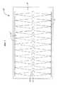
遠位セクション25、25’は、平坦状の金属ストリップまたは金属シートを所望のパターンで例えばレーザ切断によってなどで切断し、次いでパターン形成された金属ストリップまたは金属シートをハイポチューブへと巻成することにより製造され得る。代替的には、所望のパターン(例えば本明細書の様々な図中に示されるものと同一または同様のパターン)が、シートを使用するまたは材料を巻成する必要性を伴わずにチューブ(例えばハイポチューブ)へと直接的に切断され得る。一例として、図5は、図3Aの遠位セクション25用に使用され得る一例のレーザ切断ファイルまたはレーザ切断シート30の平面図を示す。このレーザ切断シート30は、遠位セクション25の長さに沿って直線列に配置された、上歯33およびそれらの関連するスロット36と、側歯31、32およびそれらの関連するスロット34、35との両方を備える。しかし、上記のように、このレーザ切断ファイル30は、歯31、32、33およびそれらの関連するスロット34、35、36が、図4に示すものと同様の湾曲状またはらせん屈曲状の遠位セクション25’を形成するように、例えばらせんライン列など、他の異なる経路または構成で配置されるように修正され得る。他の実施形態では、術中に植込み部位において定位置へとアンカリングデバイスを正確に誘導および展開するのを補助する他の形状または構成で屈曲し得る遠位セクションを実現する様々なパターンが切断され得る。 The
チューブ材へと折り曲げられ得る多数のタイプのシートが、切断された遠位セクションを作製するために使用され得る。さらに多数のタイプのチューブが、所望のパターンへと切断され得る。例えば、ニチノールおよびステンレス鋼、ならびに当技術において既知の様々な他の適切な金属が、シートまたはチューブ用の材料として使用され得る。 Many types of sheets that can be folded into tubing can be used to create a cut distal section. Further, many types of tubes can be cut into the desired pattern. For example, nitinol and stainless steel, as well as various other suitable metals known in the art, may be used as the material for the sheet or tube.
上記の実施形態は、各リンク38が合計で3つの歯を有するように、上歯および側歯の両方を備えるが、他の実施形態は、上歯もしくは側歯のいずれか一方のみを備えるか、またはまったく歯を備えなくてもよい。 While the above embodiments include both upper and side teeth, such that each
図6は、送達カテーテルの遠位セクション25’’用の別の例のレーザ切断シート30’’の平面図である。図6の遠位セクション25’’は、図5の遠位セクション25と同様であるが、遠位セクション25’’のリンク38’’は、2つの側歯31、32およびそれらの関連するスロット34、35を備えるにすぎず、上歯または対応するスロットを備えない。 FIG. 6 is a plan view of another example laser cutting sheet 30 '' for the distal section 25 '' of the delivery catheter. The distal section 25 '' of FIG. 6 is similar to the
図7は、送達カテーテルの遠位セクション25’’’用の別の例のレーザ切断シート30’’’の平面図である。図7の遠位セクション25’’’もまた、図5の遠位セクション25と同様であるが、遠位セクション25’’’の各リンク38’’’は、単一の上歯33およびその関連するスロット36を備えるにすぎず、側歯または対応するスロットを備えない。 FIG. 7 is a plan view of another example
他の実施形態では、4つ以上または2つ以下の歯が、任意の組合せにおいて各リンクに備えられ得る。一方で、図6および図7では、歯がそれぞれ遠位セクション25’’、25’’’の長さに沿って直線列で配置されるのが示されるが、レーザ切断シート30’’、30’’’は、上記で論じたのと同様に、特定の所望の形状で屈曲し得る遠位セクションを有するために様々な歯パターンおよび歯配置を備えるように修正されることも可能である。 In other embodiments, more than three or less than two teeth may be provided on each link in any combination. On the other hand, FIGS. 6 and 7 show that the teeth are arranged in a straight line along the length of the distal section 25 '', 25 '' ', respectively, but the laser cutting sheets 30' ', 30' ' The '' 'can also be modified to include various tooth patterns and arrangements to have a distal section that can bend in a particular desired shape, as discussed above.
様々なシース設計およびカテーテル設計が、植込み部位にてアンカリングデバイスを効果的に展開するために使用され得る。例えば、僧帽位置にて展開するために、送達カテーテルは、カテーテルから展開されたコイルアンカーが、前進中に左心室により容易に進入し腱62を包囲することが可能となるように、形状設定され交連A3P3に向けて位置決めされ得る。しかし以下で説明される本発明の様々な例の実施形態は、僧帽弁の交連A3P3に送達カテーテルの遠位開口を位置決めするように構成される一方で、他の実施形態では、送達カテーテルは、代わりに交連A1P1に向かうように僧帽平面にアプローチすることが可能であり、アンカリングデバイスは、この交連A1P1を貫通して前進されることが可能である。さらに、カテーテルは、僧帽弁の交連または別の天然弁の所望の交連のいずれかにアプローチするために時計回り方向または反時計回り方向のいずれかに屈曲することが可能であり、アンカリングデバイスは、時計回り方向または反時計回り方向のいずれかに植え込まれるまたは挿入されることが可能である(例えば、アンカリングデバイスのコイル/巻線が、アンカリングデバイスが植え込まれる様式に応じて時計回り方向巻きまたは反時計回り方向巻きを成し得る)。 Various sheath and catheter designs can be used to effectively deploy the anchoring device at the implantation site. For example, for deployment in the mitral position, the delivery catheter is shaped so that the coil anchor deployed from the catheter can more easily enter the left ventricle and encircle the
さらに他の実施形態では、カテーテル自体もまた、天然弁の弁輪の平面の下方を通過し、交連の中の1つの中に着座するように、または心室内に延在する(交連の中の1つを貫通して)ように位置決めされ得る。いくつかの実施形態では、カテーテルの遠位端部は、一部またはすべての腱索62を捕捉するおよび/または捕えるためにさらに使用され得る。カテーテルは、アンカリングデバイスが植込み部位にて展開されることを可能にする任意の適切な様式で位置決めされ得る。いくつかの実施形態では、カテーテル自体が、例えば、カテーテルが植込み部位に位置決めされている間に、カテーテルの前進および/または形状操作により引き起こされる恐れのあり得る損傷を軽減するまたはなくすことなどによって、植込み部位への非外傷性アクセスを可能にするための非外傷性先端部設計を有し得る。 In still other embodiments, the catheter itself also passes below the plane of the annulus of the natural valve and extends to sit in one of the commissures or into the ventricle (in the commissure). (Through one). In some embodiments, the distal end of the catheter may be further used to capture and / or capture some or all
送達カテーテルの遠位セクションに関する上記の実施形態の中のいくつかは、歯および対応するスロットを備えるが、遠位セクションに関する他の実施形態は、歯も対応するスロットも備えないことが可能である。図19は、送達カテーテル用に使用され得る別の例の遠位セクション25’’’’の斜視図である。この実施形態では、遠位セクション25’’’’は、可撓性材料から作製された堅いの略円筒状の中空チューブである。可撓性材料は、例えばニチノール、鋼、および/またはプラスチック、あるいはアンカリングデバイスを送達する間に遠位セクション25’’’’を曲げ構成へと動かすことを可能にする材料の任意の他の適切な材料もしくはその組合せであることが可能である。図示する実施形態は、略円筒状のチューブである遠位セクション25’’’’を示すが、代替的な実施形態では、遠位セクション25’’’’の形状は、アンカリングデバイスの送達を可能にする任意の適切な形状をとることが可能である点を理解されたい。遠位セクションのいくつかの実施形態は、線形スリットおよび/または矩形窓を備え得る。 Some of the embodiments described above for the distal section of the delivery catheter include teeth and corresponding slots, while other embodiments for the distal section may not include teeth and corresponding slots. . FIG. 19 is a perspective view of another example
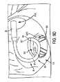
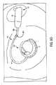
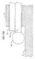
図8は、送達カテーテル64の遠位セクション65の湾曲構成または「ホッケースティック」構成の斜視図を示す。この構成は、天然弁に(例えば経中隔技術などを利用して天然僧帽弁に)アンカリングデバイスを植え込むために使用され得る。「ホッケースティック」構成では、経中隔シース20から延在する送達カテーテル64の遠位端部65は、4つの主要な下位セクションを、すなわち軽度湾曲部分66を形成する第1の曲げセクションと、円形または湾曲状の平坦部分67、巻線部68、および可撓性端部部分69を形成する第2の曲げセクションとを有する。これらの下位セクションの形状により、遠位セクション65は、天然弁(例えば天然僧帽弁)において送達カテーテル64を定位置に誘導し、天然弁にて(例えば僧帽位置にて)アンカリングデバイスを正確に展開することが可能となる。遠位セクション65は、例えば本願内で説明される任意の形状などの、遠位セクションが上述の曲げ構成をとることを可能にする任意の適切な形状をとることが可能である。一方で、図示する実施形態では、送達カテーテル64の遠位セクション65は、時計回り方向に湾曲し、他の実施形態では(例えば図9A〜図9Uの実施形態に示すように)、遠位セクション65は、例えば円形/湾曲状平坦部分67および/または巻線部68などにおいて、代わりに逆の反時計回り方向へと湾曲することが可能である。 FIG. 8 shows a perspective view of the curved or “hockey stick” configuration of the
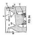
図9A〜図9Uは、患者の天然弁に(例えば経中隔技術を利用して患者の天然僧帽弁50に)アンカリングデバイス(本明細書において説明される他のアンカリングデバイスと同一または同様のものであり得る)を送達するおよび植え込む送達デバイス(本明細書において説明される他の送達デバイスと同一または同様のものであり得る)の別の例の実施形態を示す。図9Aは、心房中隔を貫通して(卵円窩(FO)にて行われ得る)左心房内へと進むシース20(例えばガイドシースまたは経中隔シース)と、シース20から延在する送達カテーテル64とを示す、患者の心臓の左心房の破断図である。図9Bは、左心房51から僧帽弁50にて見下ろした場合の(すなわち図9Aの線B−Bに沿って見た場合の)、図9Aに示す位置にある経中隔シース20および送達カテーテル64を示す。図9Aを参照すると、シース20は、シースが僧帽弁50の平面に対して実質的に平行になるように左心房に進入する。シース20および送達カテーテル64は、例えば本願で説明される任意の形状などの任意の適切な形状をとり得る。 FIGS. 9A-9U illustrate an anchoring device (e.g., identical to or other anchoring device described herein) on a patient's natural valve (e.g., using transseptal technique to patient's natural mitral valve 50). 7 illustrates another example embodiment of a delivery device for delivering and implanting (which may be the same) (which may be the same or similar to other delivery devices described herein). FIG. 9A shows a sheath 20 (eg, a guide sheath or transseptal sheath) that extends through the atrial septum and into the left atrium (which may be done at the fossa ovalis (FO)) and extends from the
いくつかの実施形態では、シース20は、中隔および/またはFO壁に対してある角度(例えば30度または約30度の角度)を成すまで位置決めされ得るまたは屈曲され得るように、作動され得るまたは操縦可能であり得る。いくつかの実施形態では、角度配向(例えば30度の角度配向)が、シース20を回転させるまたはさらに作動させることにより調節または制御され、送達カテーテル64が左心房に進入する配向をより良好に制御するために調節され得る。他の実施形態では、中隔および/またはFOに対するシース20の偏向角度は、各状況に応じて30度超または30度未満のいずれかであることが可能であり、いくつかの用途では、中隔および/またはFOに対して90度に配向されるまたは90度となるように屈曲されることもさらに可能である。いくつかの実施形態では、シースの偏向角度は、例えば約5度〜約80度の間で、約10度〜約70度の間で、約15度〜約60度の間で、約20度〜約50度の間で、約25度〜約40度の間で、約27度〜約33度の間でなど、約0度〜約90度の間で移動され得る。 In some embodiments, the
図9C〜図9Dを参照すると、外方シースまたはガイドシース20が、中隔および/またはFOを貫通して進み、所望の位置に配置された後で、送達カテーテル64は、シース20から出て延出する。送達カテーテルは、円形状または湾曲状の平坦部分67を有する遠位端部65を備えるように制御される。図示する実施形態では、送達カテーテル64の遠位端部65は、遠位端部65が反時計回り方向において湾曲して円形状/湾曲状平坦部分67を形成するように動かされる(アンカリングデバイスは、さらに反時計回り方向にコイルを成すことも可能である)。代替的な実施形態では、遠位端部65は、時計回り方向に湾曲して円形状/湾曲状平坦部分67を形成するように動かされる(この実施形態では、アンカリングデバイスは、時計回り方向にコイルを成すことも可能である)。 With reference to FIGS. 9C-9D, after the outer sheath or guide
図9E〜図9Fを参照すると、さらに送達カテーテル64は、遠位端部65の軽度湾曲部分66によって下方に延伸する。図9Eに示すように、送達カテーテル64は、遠位端部65の円形状/湾曲状平坦部分67がFO壁の概して約30〜40mm下方の位置となる僧帽弁50の平面に接近するまで、下方へと延伸される。しかし、いくつかの状況では、僧帽弁の平面は、FOの30mm未満下方または30mm超下方の位置となり得る。いくつかの実施形態では、送達カテーテル64は、外方シースから例えば50mm以下、45mm以下、40mm以下、35mm以下、30mm以下、25mm以下、20mm以下など、60mm以下だけ延在するように構成される。いくつかの実施形態では、外部シースからの送達カテーテル64の最大延在長さは、例えば約25mm〜約50mmの間、約30mm〜約40mmの間など、約20mm〜約60mmの間である。いくつかの実施形態では、送達カテーテル64は、送達カテーテル64の1つまたは複数の作動ポイント70、71に係合することにより、本明細書において説明される様々な構成の中の任意のものへと動かされ得る。 Referring to FIGS. 9E-9F, the
円形状/湾曲状平坦部分67は、僧帽弁50の平面の上面の付近に、上面の上に、または実質的に上面の上に位置するように前進されるまたは下げられる。弁輪のレベルまでまたはその付近まで下げられると、平坦部分67または平坦部分67の平面は、弁輪の平面と平行にまたは略平行に(例えば平坦状にもしくは略平坦状に)なり得るか、あるいは平坦部分67は、弁輪の平面に対して若干上方に角度をつけられ得る。また、送達カテーテル64は、交連A3P3に向かって戻るように旋回するように湾曲状をなす。送達カテーテル64は、例えばプルワイヤもしくはリングシステム、または本願内の他の部分において説明されるものなどを含む任意の他の適切な手段などの、任意の適切な手段により円形状/湾曲状平坦部分67および/または軽度湾曲部分66を形成するように動かされ得る。図示する実施形態は、遠位端部65が、軽度湾曲部分66を形成するように移動される前に、円形状または湾曲状平坦部分67を形成するように移動されることを示すが、軽度湾曲部分66を形成するために遠位端部65を下方に延伸させることは、円形状または湾曲状平坦部分67を形成するために遠位端部65が反時計回り方向に湾曲される前に実施されることが可能である点を理解されたい。 The circular / curved
図9G〜図9Hを参照すると、遠位セクション65の調節を可能にする作動ポイント70(および/または1つまたは複数の他の作動ポイント)が、軽度湾曲部分66と円形状/湾曲状平坦部分67との間に位置することが可能である。図示する実施形態では、作動ポイント70は、可撓性端部69および遠位先端部907が僧帽弁50の交連A3P3の方向におよび/または交連A3P3中に弁輪の下方に(または弁輪の上方平面の下方に)延在するように、平坦部分67および可撓性端部69が幾分か下方に角度をつけられるように調節されることが可能である。すなわち、第1の作動ポイント70は、平坦部分67(および結果として可撓性端部69)が交連A3P3に向かって下方へと角度をつけられ、この交連にてまたはその付近にて位置決めされる(例えば1〜5mmまたはそれ未満など交連の中にまたは交連を貫通して若干延在する)ように、作動され得る。さらなる作動ポイント70に加えてまたはその代替として、送達デバイス(例えばシースおよび/または送達カテーテル)は、円形状/湾曲状平坦部分67の角度が所望に応じて交連に向かっておよび/または交連の中へと下方に角度をつけられるように、トルクを与えられ得るまたは回転され得る。時として、このトルク付与または回転は、湾曲部分の作動によりカテーテルの遠位領域が所望に応じて完全には位置決めされない場合に、角度を直角にするために必要となり得る。いくつかの実施形態では、第2の作動ポイント71が、部分67と可撓性端部69との間に位置し得る。 Referring to FIGS. 9G-9H, an actuation point 70 (and / or one or more other actuation points) that allows adjustment of the
図9Iは交連A3P3を貫通してならびに患者の心臓の左心室52における腱索62および天然弁葉の周囲においてアンカリングデバイス1の一例の実施形態を展開する送達カテーテル64を示す。アンカリングデバイス1またはより大きな直径もしくは曲率半径を有するアンカリングデバイスの下方端部または包囲コイル/巻線は、送達カテーテル64の遠位開口から出て、送達カテーテル64の円形状または湾曲状の平坦部分67の方向に形状設定された形状または形状記憶形状をとり始める。 FIG. 91 shows a
アンカリングデバイス1が僧帽弁50の交連A3P3を貫通して動くために、送達カテーテル64は、送達カテーテル64の円形状/湾曲状平坦部分67および可撓性端部69の遠位開口が下方へと角度をつけられ、可撓性端部69の遠位開口が交連A3P3に向かっておよび/または交連A3P3の中に送られるように、位置決めされる。円形状/湾曲状平坦部分67および可撓性端部69の遠位開口が下方に向けられる結果として、アンカリングデバイス1は、送達カテーテル64から下方へ出る。アンカリングデバイス1は、送達カテーテル64から出た後に、形状設定された形状または形状記憶形状をとるように湾曲し始める。円形状/湾曲状平坦部分が下方へと角度をつけられることにより、アンカリングデバイス1は、図9Iに示すように、アンカリングデバイスの約1/2回転部分が展開された後に上方へと湾曲し始める。アンカリングデバイス1または下方端部/包囲コイル/巻線が、送達カテーテル64から外に展開されつつあるときに上方へと僧帽弁50に係合するのを防止するために、アンカリングデバイスが、腱索62の周囲に巻きつけられ始めると(図9Iに示すように)、送達カテーテル64は、円形状/湾曲状平坦部分67が僧帽弁50の平面に対して実質的に平行になるように動かされ得る(例えば作動ポイント70を動かすことにより)(図9Lを参照)。これは、所望に応じて平坦部分67の角度を調節するために箇所70において作動させるおよび/または送達デバイスもしくはその一部分(例えば送達カテーテル)にトルクを与えるもしくは作動させることにより実施され得る。 For the
図9Jを参照すると、円形状/湾曲状平坦部分67が、僧帽弁輪と実質的に同一平面をなすように動かされた後に、アンカリングデバイス1は、僧帽弁50の平面に対して実質的に平行となる定位置にて腱索62の周囲に巻き付くように、送達カテーテル64からさらに展開され得る。これにより、アンカリングデバイスは、上方向に湾曲することならびに僧帽弁輪の下側および/または左心室の上壁に係合することを防止される。 Referring to FIG. 9J, after the circular / curved
図9Kを参照すると、アンカリングデバイス1は、心臓弁を保持するために僧帽弁の心室側においてアンカリングデバイスを緩く位置決めするために腱索62の周囲に配設される。図示する実施形態では、アンカリングデバイス1は、アンカリングデバイスの3つの機能コイル12が腱索および/または天然弁葉の周囲に緊密に巻き付けられるように、左心室52内に配設される。下方端部巻線/コイルまたは包囲巻線/コイルは、その曲率半径がより大きいため幾分か外方に延在するのが分かる。いくつかの実施形態では、アンカリングデバイス1は、腱索および/または弁葉の周囲に配設される2つ以下のコイル12または4つ以上のコイル12を備えることが可能である。 Referring to FIG. 9K, anchoring
図9Lは、アンカリングデバイスのコイル12が腱索62および天然弁葉の周囲に配設された後に(図9Kに示すように)、ある位置にある左心房51内の送達カテーテル64を示す。この位置では、送達カテーテル64の円形状/湾曲状平坦部分67は、僧帽弁50の平面に対して実質的に平行であり、可撓性端部69は、僧帽弁50の交連A3P3にまたはその付近に位置する(例えば1〜5mmまたはそれ未満などだけ交連A3P3の中にまたは貫通して若干延在して)。 FIG. 9L shows the
図9Mを参照すると、送達カテーテル64およびアンカリングデバイス1が、図9K〜図9Lに示すように位置決めされた後に、送達カテーテルは、方向Xにおよび外方シース20内へとアンカリングデバイスに沿って軸方向に並進移動または後退される。送達カテーテルの並進移動または後退により、天然弁の心房側に(例えば心房内に)位置決めされたアンカリングデバイスの一部が、送達カテーテルから抜き出され放出され得る。例えば、これにより、天然弁の心房側に位置決めされた任意の機能コイルおよび/または上方コイルの任意の上方部分(それが存在する場合)が抜き出され放出され得る。一例の実施形態では、アンカリングデバイス1は、送達カテーテルが並進移動されることにより移動せずまたは実質的に移動せず、例えば、プッシャが、アンカリングデバイスを定位置に保持するために、および/または送達カテーテルが後退される場合にアンカリングデバイスの後退を阻止もしくは防止するために使用され得る。 9M, after the
図9Nを参照すると、図示する例では、送達カテーテルの並進移動または後退により、送達カテーテルからアンカリングデバイス1の任意の上方端部コイル/巻線(例えばより大きな直径の安定化コイル/巻線)がやはり抜き出され得る/放出され得る。この抜出し/放出の結果として、アンカリングデバイスまたは上方コイル(例えばより大きな直径または曲率半径を有する安定化コイル)の心房側部分が、送達カテーテル64から延出し、事前設定されたまたは弛緩した形状設定/形状記憶形状をとり始める。また、アンカリングデバイスは、屈曲部Zから上方に延在する上方延在部分または連結部分を備えることが可能であり、アンカリングデバイスの上方端部安定化コイル/巻線と他のコイル/巻線(例えば機能コイル/巻線)との間に延在および/またはブリッジし得る。いくつかの実施形態では、アンカリングデバイスは、天然弁の心房側に1つのみの上方コイルを有し得る。いくつかの実施形態では、アンカリングデバイスは、天然弁の心房側に2つ以上の上方コイルを備え得る。 Referring to FIG. 9N, in the example shown, any upper end coil / winding of the anchoring device 1 (eg, a larger diameter stabilizing coil / winding) from the delivery catheter by translation or retraction of the delivery catheter. Can also be extracted / released. As a result of this withdrawal / ejection, the atrial portion of the anchoring device or upper coil (e.g., a stabilizing coil having a larger diameter or radius of curvature) extends from the
図9Oを参照すると、送達カテーテル64は、外方シースまたはガイドシース20内へと戻るように並進移動し続け、これにより、アンカリングデバイス1の上方部分は、送達カテーテル内部から放出される。アンカリングデバイスは、縫合糸/ライン901などの装着手段によりプッシャ950に対して緊密に連結される(図17A〜図18Cにおけるように他の装着手段または連結手段もまた使用され得る)。上方端部コイル/巻線または安定化コイル/巻線は、僧帽弁50に対するアンカリングデバイス1の位置または高さを一時的におよび/または緩く保持するために、心房壁に沿って配設されるものとして示される。 Referring to FIG. 90, the
図9Pを参照すると、アンカリングデバイス1は、送達カテーテル64のルーメンから完全に除去され、弛みが、アンカリングデバイス1に対して除去可能に装着された縫合糸/ライン901中に見られ、例えば、縫合糸/ライン901は、アンカリングデバイスの端部に位置する目穴を貫通して輪を形成し得る。送達カテーテル64からアンカリングデバイス1を除去するために、縫合糸901がアンカリングデバイスから除去される。しかし、縫合糸901が除去される前に、アンカリングデバイス1の位置が確認され得る。アンカリングデバイス1の位置が不正確である場合には、アンカリングデバイスは、プッシャ950(例えばプッシャロッド、プッシャワイヤ、プッシャチューブ等)により送達カテーテル内へと引き戻され、再展開され得る。 Referring to FIG. 9P, the
図9Qを参照すると、送達カテーテル64および外方シース20がアンカリングデバイス1から装着解除された後に、心臓弁送達デバイス/カテーテル902が、僧帽弁50に心臓弁903を送達するために使用され得る。心臓弁送達デバイス902は、送達カテーテル64および/または外方シースもしくはガイドシース20の構成要素の中の1つまたは複数を使用してもよく、あるいは送達カテーテル64および外方シースもしくはガイドシースとは別個であってもよい。図示する実施形態では、心臓弁送達デバイス902は、経中隔アプローチを利用して左心房51に進入する。 Referring to FIG. 9Q, after the
図9Rを参照すると、心臓弁送達デバイス/カテーテル902は、心臓弁903が僧帽弁の弁葉とアンカリングデバイス1との間に配置されるように、僧帽弁50を貫通して移動される。心臓弁903は、ガイドワイヤ904に沿って展開位置まで案内され得る。 Referring to FIG. 9R, the heart valve delivery device /
図9Sを参照すると、心臓弁903が所望の位置に配置された後に、オプションのバルーンが、心臓弁903を拡張展開サイズまで拡張させるために拡張される。すなわち、オプションのバルーンは、心臓弁903が僧帽弁50の弁葉に係合し、心室巻線を拡大サイズまで外方へと付勢し、それにより心臓弁903とアンカリングデバイスとの間に弁葉を固定するように膨張される。心臓弁903の外方力およびコイル1の内方力は、天然組織を挟み、弁葉に対して心臓弁903およびコイルを保持することが可能である。いくつかの実施形態では、自己拡張型心臓弁が、心臓弁送達デバイス902のシース内に径方向圧縮状態で保持され、心臓弁は、シースから展開されることにより、拡張状態へと拡張され得る。いくつかの実施形態では、機械的拡張型心臓弁が使用され、または部分的機械的拡張型心臓弁(例えば自己拡張と機械拡張との組合せにより拡張し得る弁)が使用される。 Referring to FIG. 9S, after the
図9Tを参照すると、心臓弁903が拡張状態へと動かされた後に、心臓弁送達デバイス902およびワイヤ904(図9Tにも依然として図示される)が、患者の心臓から除去される。心臓弁903は、機能状態にあり、患者の心臓の僧帽弁50の機能を置換する。 Referring to FIG. 9T, after
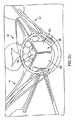
図9Uは、図9Tの線U−Uに沿った左心室52内を上方から見た場合の心臓弁903を示す。図9Uでは、心臓弁903は、拡張状態および機能状態にある。図示する実施形態では、心臓弁903は、開位置と閉位置との間で動くように構成された3つの弁部材905a〜905c(例えば弁葉)を備える。代替的な実施形態では、心臓弁903は、開位置と閉位置との間で動くように構成された4つ以上の弁部材または2つ以下の弁部材を、例えば2つ以上の弁部材、3つ以上の弁部材、4つ以上の弁部材等を有することが可能である。図示する実施形態では、弁部材905a〜905cは、閉位置において示され、これは、左心室から左心房内への血液の移動を防止するために弁部材が収縮期の最中にある位置である。拡張期中には、弁部材905a〜905cは、開位置へと動き、それにより血液は左心房から左心室に進入することが可能となる。 FIG. 9U shows the
図9A〜図9Uに示す実施形態は、交連A3P3を貫通してアンカリングデバイス1を送達する送達カテーテル64を示すが、アンカリングデバイス1が患者の心臓の左心室内で腱索の周囲に巻き付けられ得るように、送達デバイス64が交連A1P1を貫通してアンカリングデバイス1を送達するような構成をとり位置決めされ得る点を理解されたい。さらに、図示する実施形態は、僧帽弁までアンカリング部材1を送達する送達カテーテル64と、僧帽弁50まで心臓弁903を送達する心臓弁送達デバイス902とを示すが、アンカリングデバイス1および心臓弁903は、三尖弁、大動脈弁、または肺動脈弁を修復するために必要に応じて変更を加えて使用され得る点を理解されたい。 The embodiment shown in FIGS. 9A-9U shows a
一実施形態では、送達カテーテル64の遠位セクション65は、堅いの略円筒状の中空チューブ(例えば図19において説明される遠位セクション25’’’’)であることが可能である。 In one embodiment, the
本明細書における様々な送達カテーテルのガイドシースおよび/または遠位セクションは、送達カテーテルを所望の構成へと制御または作動するための1つまたは複数のプルワイヤ(例えば2〜6個のプルワイヤ)を備え得る。例えば、本明細書における様々な送達カテーテルの遠位セクションが、2プルワイヤシステム(例えば図20A〜図23において説明される2プルワイヤシステム)を有することが可能である。例えば、図9A〜図9Uに示す構成、図8において示す「ホッケースティック」形状構成、または本願において説明される任意の他の構成が、例えば上記で論じた作動ポイント70、71にまたはその付近に位置決めされた2つのプルリングから構成された可撓性チューブカテーテルを使用することにより実現されることも可能である。これらのプルリングは、それぞれのプルワイヤに係合され得るまたは連結され得る。プルワイヤは、送達カテーテルの周囲において周方向に相互から90°離れるように位置決めされ得る。例えば遠位セクション65に沿ってほぼ半分の位置に位置決めされる第1のプルリングが、天然弁平面上に(例えば僧帽平面上に)送達カテーテルの遠位領域を引くように第1のプルワイヤにより作動され得る一方で、送達カテーテルの遠位先端部位907にてまたはその付近にてさらに遠位に位置決めされた第2のプルリングは、例えば必要に応じて天然弁平面の周囲において(例えば僧帽平面の周囲において)および所望の交連(例えば僧帽交連A3P3)に向かっておよびさらに遠くになど、異なる方向へとカテーテル湾曲を向けるように別のプルワイヤによって作動され得る。 The guide sheath and / or distal section of the various delivery catheters herein include one or more pull wires (eg, 2-6 pull wires) to control or actuate the delivery catheter to a desired configuration. obtain. For example, the distal sections of the various delivery catheters herein can have a two-pull wire system (eg, the two-pull wire system described in FIGS. 20A-23). For example, the configuration shown in FIGS. 9A-9U, the “hockey stick” shaped configuration shown in FIG. 8, or any other configuration described herein, for example, at or near the operating points 70, 71 discussed above. It can also be realized by using a flexible tube catheter composed of two pull rings positioned. These pull rings may be engaged or connected to respective pull wires. The pull wires may be positioned around the
いくつかの実施形態では、2つのプルリングは、例えば最遠位プルリング用の対向側プルワイヤなど、プルワイヤの中の径方向対向側のプルワイヤ上に実装されるスパインにより連結され得る。かかる追加されたスパインは、これらのプルリング間の相対移動を制限し、最遠位プルリング用のプルワイヤを引くことにより引き起こされる偏向方向をより良好に制御するのを補助して、僧帽平面に対して垂直な方向または他の意図しない方向への可撓性遠位セクションの偏向を防止し得る。上述の実施形態は、3つのプルリングおよび2つのプルワイヤを備え得るが、任意の個数のプルリングおよび/またはプルワイヤが、本明細書において説明される様々な構成を形成するために使用され得る点を理解されたい。さらに、任意の適切な個数のスパインが、プルリング同士の間の相対移動を制限するために使用され得る点を理解されたい。 In some embodiments, the two pull rings may be connected by a spine mounted on a radially opposite pull wire in the pull wire, for example, an opposite pull wire for the most distal pull ring. Such added spines limit the relative movement between these pull rings and help to better control the direction of deflection caused by pulling the pull wire for the most distal pull ring, with respect to the mitral plane. To prevent deflection of the flexible distal section in a vertical or other unintended direction. While the embodiments described above may include three pull rings and two pull wires, it is understood that any number of pull rings and / or pull wires may be used to form the various configurations described herein. I want to be. Further, it should be understood that any suitable number of spines may be used to limit the relative movement between the pull rings.
いくつかの実施形態では、遠位セクション65は、屈曲された場合に遠位セクションが本明細書において説明される様々な構成の中のいずれかを形成するような(例えば図9A〜図9Uにおいて説明される構成、「ホッケースティック」構成、等)パターンで構成されたレーザ切断ハイポチューブ(上記の図4〜図7で説明されたレーザ切断カテーテルと同様の)であることが可能である。また、論じたように、かかるレーザ切断遠位セクションは、完全屈曲構成(例えば一方の湾曲部が僧帽平面に向かうものであり、他方の湾曲部が僧帽弁輪のほぼ周囲において湾曲する円形部分となる)にある遠位端部における二方向偏向を実現するために、例えば別個の制御部(例えばノブ、タブ、入力、ボタン、レバー、スイッチ等)または他の機構などにより制御される例えば個別のプルワイヤなどを用いて相互に独立的に作動され得る2つ以上の作動ポイントを有することが可能である。 In some embodiments, the
いくつかの実施形態では、遠位セクション65全体が、レーザ切断ハイポチューブとして構成される必要はない。例えば、遠位セクション65は、軽度湾曲部分66の近位に位置する第1の可撓性直線セクションと、カテーテルの最遠位領域を僧帽平面上へと屈曲するのを補助するように軽度湾曲部分66を構成するオプションの小レーザ切断エルボ部分と、さらに交連A3P3にカテーテルの端部を向けるように僧帽平面に沿って湾曲することが可能な遠位先端部まで延在する第2の可撓性セクションとを備え得る。第1の可撓性セクションにより、遠位セクション65は、経中隔シース20から出た後に僧帽平面の付近に近づくことが可能となり、シース20を押し通されるおよび前進されるのに十分な可撓性を有するが、アンカリングデバイスがカテーテルを通して前進および送達されている場合にアンカリングデバイスによる影響を被ることに対して依然として抵抗するのに十分な剛性を有する。第1の可撓性セクションは、例えばコイル状チューブまたは編組チューブの上に被覆された約50Dの硬度を有するポリエーテルブロックアミド(PEBAX)などで構成され得る。一方で、小レーザ切断エルボ部分は、僧帽平面上にカテーテルの遠位領域を置くのを支援するために約150°の最大偏向幅を有し得る。最後に、第2の可撓性セクションは、送達カテーテルの遠位先端部まで延在し、交連A3P3にカテーテルを向けるようにおよび上記ですでに論じたのと同様に腱がアンカリングデバイスにより包囲されるのを支援するために場合によってはさらに曲がるように構成され得る。また、第2の可撓性セクションは、例えば約55Dの硬度を有するおよびコイル状チューブまたは編組チューブの上にやはりリフローされた、例えばPEBAXなどを用いて構成され得る。この構成を使用することにより、レーザ切断ハイポチューブとして遠位セクション65全体を形成するまたはレーザ切断ハイポチューブから任意の部分を形成する必要を伴うことなく、上記で論じたレーザ切断ハイポチューブと実質的に同様に形状設定および作動され得る遠位セクション65が依然としてもたらされ得る。 In some embodiments, the entire
遠位セクション65を有する送達カテーテル64が、上述の実施形態を用いて説明されるが、上述の実施形態は例にすぎない点を理解されたい。送達カテーテル64は、本明細書において説明される形状構成の形成を可能にする任意の適切な形状をとることが可能である。さらに、送達カテーテルは、本明細書において説明される形状構成を形成することが可能である任意の適切な材料で作製され得る。 Although a
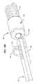
図10は、天然弁にアンカリングデバイス(本明細書において説明される他のアンカリングデバイスと同一または同様のものであり得る)を植え込むための送達カテーテル74(本明細書において説明される他の送達カテーテルと同一または同様のものであり得る)の一例の遠位セクション75の斜視図を示す。僧帽弁に関して、この植込みは、経中隔技術を利用して実施され得る。送達カテーテルは、らせん構成の一例を呈するものとして示される。「ホッケースティック」構成とは異なり、および図9A〜図9Uにおいて論じた構成と同様に、シース20は、天然弁輪の平面(例えば僧帽平面)に対して平行な方向においてFOを貫通して延在する。この実施形態では、さらに、遠位セクション75は、シース20から出て、僧帽弁の交連A3P3まで下方に約1巻き分にわたり延在する。遠位セクション75は、カテーテルの遠位端部が最初に展開中に天然弁輪平面の下方に延在し得るらせん体で形状設定され得る。次いで、ユーザは、患者の心臓の天然弁輪平面の上または直上に遠位端部がくる状態にするために、カテーテルに組み込まれたまたは装着された曲げワイヤに対して上方張力を印加することなどによって、遠位端部の高さを調節し得る。 FIG. 10 illustrates a delivery catheter 74 (other described herein) for implanting an anchoring device (which may be the same or similar to other anchoring devices described herein) into a native valve. FIG. 4 shows a perspective view of an example distal section 75 (which may be the same or similar to a delivery catheter). With respect to the mitral valve, this implantation can be performed utilizing a transseptal technique. The delivery catheter is shown as exhibiting an example of a helical configuration. Unlike the “hockey stick” configuration, and similar to the configurations discussed in FIGS. 9A-9U, the
いくつかの実施形態では、遠位セクション75は、全体がレーザ切断ハイポチューブ(図4〜図7において上述したレーザ切断カテーテルと同様の)であることが可能であり、屈曲された場合に遠位セクションがらせん構成を形成するようなパターンで切断部が配置される。いくつかの実施形態では、レーザ切断ハイポチューブのらせん構成は、天然弁輪平面まで伸長または延在する(例えば僧帽平面よりも下方の位置までFOから伸長または延在する)らせん体へと形状設定されることが可能である。上歯とそれらの関連するスロットとの間のそれぞれの間隙(例えば、歯がそれらのそれぞれのスロット内に位置する場合に歯が径方向に移動するための空間を形成するように、スロットが歯よりも径方向に幅広である)により、カテーテルの垂直方向伸長が可能となる。遠位セクションは、この垂直方向伸長構成で形状設定され得る。この場合に、らせん体が僧帽解剖学的構造体内に位置するときに、カテーテルの遠位先端部は、例えばカテーテルの遠位セクション内のまたは先に論じたようにカテーテルの遠位セクションに対して装着された曲げワイヤを曲げるもしくは張力をかけることなどにより、僧帽平面に沿ってまたはその直上に位置をとるように引き上げられ得る。この特徴により、らせん体は、種々の患者の解剖学的構造体に対応するために様々な高さへと調節されることが可能となる。 In some embodiments, the
らせん構成を有する送達カテーテル74を使用する別の実施形態では、遠位セクション75は、レーザ切断ハイポチューブとして構成されなくてもよく、代わりに被覆されたコイルとして形成され得る。例えば、カテーテルは、例えば被覆された約55Dの硬度を有する低デュロメータPEBAXを含む編組チューブまたはコイル状チューブによって形成され得る。曲げられた場合に、カテーテルは、上記で論じたものと同様のらせん構成をとり得る。一方で、らせん体の高さを制御するために、送達カテーテルのシャフトに沿って延在しカテーテルの遠位端部に対して任意に連結されるプルワイヤが備えられ得る。プッシャワイヤは、カテーテルの遠位端部が天然弁輪平面(例えば僧帽平面)に対して押し付けられるおよび/または引っ張られるのを可能にするために十分な強度および物理特性を有する。例えば、プッシャワイヤは、NiTiワイヤ、鋼、または任意の他の適切なワイヤであることが可能である。一実施形態では、遠位端部が天然弁輪平面の下方に(例えば僧帽平面の下方に)進む場合には、プッシャワイヤを押すことにより、らせん体の遠位端部が下げられ、プッシャワイヤを引き戻すことにより、送達カテーテルの遠位端部が上げられる。 In another embodiment using a
らせん構成を有する送達カテーテル74を使用する別の実施形態では、遠位セクションは、レーザ切断または他の方法で切断されなくてもよい(例えば図19に示す遠位セクション25’’’’と同様に)。例えば、送達カテーテル74の遠位セクション75は、らせん構成へと送達カテーテル74を動かすように構成されたプルリング、プルワイヤ、および/またはスパインを有して構成された可撓性チューブカテーテルによって形成され得る。 In another embodiment using a
遠位セクション75を有する送達カテーテル74が上述の実施形態を用いて説明されたが、上述の実施形態は例にすぎない点を理解されたい。送達カテーテル74は、らせん構成を形成し得る任意の適切な形状をとり得る。さらに、送達カテーテルは、らせん構成を形成し得る任意の適切な材料で作製され得る(例えば遠位セクション75は、図20A〜図23に示す送達カテーテル114の形状をとり得る)。 Although a
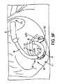
図11は、送達カテーテル104の遠位セクション105のハイブリッド構成の斜視図を示す。送達カテーテル104は、上記で論じた「ホッケースティック」構成およびらせん構成の両方からの特徴を組み合わせたものである。ハイブリッド構成では、「ホッケースティック」構成と同様に、送達カテーテル104の遠位セクション105は、初めに僧帽平面に向かってカテーテル104を屈曲するための軽度湾曲部分または軽度屈曲部分106を有する。代替的な実施形態では、カテーテル104は、屈曲部分106の近位曲げを増大させることによって屈曲される。軽度湾曲部分に続いて、例えば図示するように反時計回り方向などに湾曲を開始する円形状または湾曲状の平坦部分107が存在し得る。他の実施形態では、送達カテーテル104は、代わりに時計回り方向に屈曲または湾曲し得る(例えば図8に示すように)。平坦部分107は、僧帽平面に対して実質的に平行であることが可能である。 FIG. 11 shows a perspective view of a hybrid configuration of the
一方で、平坦部分107の遠位には、可撓性端部部分108が存在し、この可撓性端部部分108は、交連または他の標的に向かってまたは貫通するように送達カテーテル104の遠位開口をより効果的に向けるために、平坦部分107が配置される平面から若干下方へと屈曲され得る、角度をつけられ得る、または他の様式で向けられ得る。いくつかの実施形態では、可撓性端部部分108は、送達カテーテル104の下方らせん状領域を形成し得る。可撓性端部部分108は、例えば約3mm〜約9mmの間、約4mm〜約8mmの間、約5mm〜約7mmの間、約6mmなど、約2mm〜約10mmの間で垂直方向へと平坦部分107から偏向または変位され得る。他の実施形態では、垂直変位は、約3mm以上、約4mm以上、約5mm以上、約6mm以上、約7mm以上、約8mm以上、約9mm以上、約10mm以上など、約2mm以上であることが可能である。さらに、いくつかの実施形態では、可撓性端部部分108(すなわち下方らせん状セクション)は、送達カテーテル104の遠位セクション105の小部分のみが、僧帽平面に対して実質的に平行な平面内に延在する、または送達カテーテル104の遠位セクション105が、まったく僧帽平面に対して実質的に平行な平面内に延在しないように、湾曲部分106から実質的に起始し得る。 On the other hand, distal to the
前述の送達カテーテルと同様に、送達カテーテル104の遠位セクション105は、レーザ切断ハイポチューブ、編組チューブカテーテルもしくはコイル状チューブカテーテル、切断部を有さない可撓性チューブ、または他の可撓性チューブ状構成体から作製され得るかまたはそれらを備え得る。いくつかの実施形態では、カテーテル104の遠位セクション105は、例えばPEBAXなどで被覆され得る。さらに、送達カテーテル104の遠位セクション105は、例えば形状設定、プルワイヤおよび/またはプルリング、スパイン、および/または本願において説明される様々な他の方法もしくは特徴の利用などにより作動または操縦され得る。 As with the delivery catheters described above, the
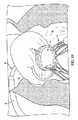
一方で、上述の実施形態では、送達デバイスは、天然弁輪平面(例えば僧帽平面)の上方に一般的にまたは殆どの場合において位置決めされ、アンカリングデバイスは、送達デバイスから押し出され、同時に依然として心房側にまたは心房を若干のみ(例えば1〜5mmまたはそれ未満)越えて位置した状態にあり、心室内へと前進され(例えば天然弁の交連を貫通して)るが、いくつかの他の実施形態では、送達デバイス自体の少なくとも一部分またはかなりの部分が、左心室内にさらに位置決めされ得る。例えば、図12は、経中隔技術を利用して天然僧帽弁にアンカリングデバイス1を設置するための送達デバイスを示し、この送達デバイス自体の遠位端部の殆ど(例えば湾曲部分または作動可能部分)が、天然僧帽弁を貫通して左心室内へとさらに前進される。 On the other hand, in the embodiments described above, the delivery device is generally or most often positioned above the natural annulus plane (eg, the mitral plane), and the anchoring device is pushed out of the delivery device while still being It is located on the atrial side or slightly beyond (e.g., 1-5 mm or less) the atrium and is advanced into the ventricle (e.g., through the commissure of the native valve) but with some other In embodiments, at least a portion or a substantial portion of the delivery device itself may be further positioned within the left ventricle. For example, FIG. 12 shows a delivery device for placing the
図12を参照すると、図示される送達デバイスは、外方ガイドシース20と、ガイドシース20の遠位端部を貫通し外へと前進され得る可撓性送達カテーテル114とを備える。図示する実施形態では、ガイドシース20は、例えば図12に示すように、初めに心房中隔中に(例えば卵円窩にて)形成された開口を通り左心房内へと操縦され得る。次いで、ガイドシース20は、天然僧帽弁輪に向かって下方へと湾曲または屈曲するように操縦されることが可能であり、それによりガイドシース20の遠位開口は、僧帽弁輪の中心軸に対して実質的に同軸的に向きをとる。ガイドシース20の垂直方向位置は、ガイドシース20の遠位開口が天然僧帽弁輪と実質的に整列されるようなものであることが可能であり、または天然僧帽弁輪の若干上方において左心房内に位置決めされることが可能であり、またはいくつかの実施形態では(図12に示すように)、天然僧帽弁輪を貫通し左心室内に延在することが可能である。 Referring to FIG. 12, the delivery device shown includes an
ガイドシース20が、実質的に図12に示すように位置決めされると、次いで送達カテーテル114は、ガイドシース20の遠位開口から外へと前進される。この実施形態では、ガイドシース20の遠位端部は、天然僧帽弁輪にまたはその若干上方に位置決めされ、それにより送達カテーテル114は、初めに左心房内へと天然僧帽弁輪の直上に前進され得る。送達カテーテル114は、初めに非作動的な実質的に直線状の構成でガイドシース20の遠位開口から外へと前進され、その後、ガイドシース20から外に前進された後に図12に示す屈曲構成へと作動され得る。いくつかの実施形態では、送達カテーテル114は、例えば本願で説明される任意の構成などの任意の他の適切な構成へと作動され得る。 Once the
可撓性送達カテーテル114は、2つ以上の主要偏向可能セクションを、例えばアンカリングデバイス1が送達カテーテル114から外に前進され植込み部位まで送達される場合にアンカリングデバイス1の形状設定を支援するための、比較的より幅広かつより円形である湾曲構成へと屈曲可能である遠位セクション115と、天然弁輪平面(例えば僧帽平面)と実質的に同一平面上にあるまたは平行である平面中に遠位セクション115を位置させるのを支援するために、例えば約90度の屈曲部であるより鋭角的な屈曲部分を形成するより近位のセクション116とを備え得る。送達カテーテル114は、例えば本願で説明される任意の形状などの任意の適切な形状をとり得る。 The
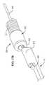
図13〜図16を参照すると、一例の実施形態では、一例の送達カテーテル114の遠位領域117が、第1の一連のスロット125および第2の一連のスロット126を有するハイポチューブから構成され得る。また、送達カテーテルは、プルワイヤシステム(例えば第1のプルワイヤ135および第2のプルワイヤ136を備える2プルワイヤシステム)を有することが可能である。図13は、送達カテーテル114の一例の実施形態の遠位セクション117の概略側面図を示す。図14は、送達カテーテル114のマルチルーメン押出成形部分の断面図を示し、この断面は、送達カテーテルの長手方向軸に対して垂直な平面内において得られたものである。図15および図16は、部分作動状態および完全作動状態にある図13の送達カテーテル114の概略斜視図をそれぞれ示す。例えば上記で論じた実施形態のいずれかにおいて示されるような種々の様式で展開および使用される他の送達カテーテルが、同様の2プルワイヤシステムで構成されることも可能である。 Referring to FIGS. 13-16, in one example embodiment, the
一実施形態では、送達カテーテル114は、2つの可撓性セクション115、116を備える遠位領域117を有する。第1の一連のスロット125は、遠位領域117の第1の側部に沿って配置されて(例えば線形的に配置されまたは他の様式で)、第1の可撓性セクション115に対して対応するおよび可撓性を与えることが可能であり、それにより第1の可撓性セクション115は、送達カテーテルが作動される場合には略円形構成を形成し得る(例えば図12に示すものと同様の構成であり得る)。第2の一連のスロット126は、遠位領域117の第2の側部に沿って線形的に配置されて、第2の可撓性セクション116に対して対応するおよび可撓性を与えることが可能であり、それにより第2の可撓性セクション116は、送達カテーテル114が作動される場合には図12に示すより鋭角的な屈曲部を形成し得る。スロット125、126は、前出の実施形態で論じたものと同様にレーザ切断もしくは形成されることが可能であり、または、スロット125、126が作動時に送達カテーテル114の所望の形状設定に寄与する限りにおいて様々な他の様式で形成されることが可能である。第2の一連のスロット126は、セクション115、116の屈曲部分に対応する第1の一連のスロット125の若干近位に位置決めされ、遠位領域117に2つの直角屈曲部を与えるために、例えば遠位領域117の周囲において約90度だけ周方向へとオフセットされることが可能であり、この場合に、セクション115、116のそれぞれの曲率半径および関節動作方向は、相互に異なることが可能である。いくつかの実施形態では、セクション115、116は、約75度〜約105度の間、約80度〜約100度の間、約85度〜約95度の間など、例えば約65度〜約115度の間などだけ周方向にオフセットされ得る。 In one embodiment, the
いくつかの実施形態では、セクション115、116のそれぞれが、セクション115、116の屈曲をそれぞれ制御するための関連するプルワイヤ135、136を有し得る。プルワイヤ135は、スロット125を越えて遠位方向に延在し、遠位領域117に対して例えば連結点135aおよび/またはプルリングにて溶接もしくは他の装着手段を介して装着され得る。同様に、プルワイヤ136は、スロット126を越えて遠位方向に延在し、遠位領域117に対して連結点136aおよび/またはプルリングにて溶接または他の方法で装着され得る。 In some embodiments, each of the
一方で、遠位領域117の近位側では、送達カテーテル114は、編組マルチルーメンチューブ延長部として形成され得る近位セクション140を備え得る。図14の断面に示されるように、送達カテーテル114の近位セクション140は、遠位領域117に届くようにプルワイヤ135、136が通り延在する1つまたは複数の中央ルーメンを有し得る。プルワイヤ135、136は、近位セクション140の中央領域を貫通して並列的に延在するように配置されることが可能であり、この場合には近位セクション140から遠位方向へと出て、前述のように遠位領域117の側壁部に対して装着され得る。近位セクション140を貫通するプルワイヤ135、136の中央位置決めにより、プルワイヤ135、136が使用される場合の送達カテーテル114を介した急動防止効果または屈曲防止効果がもたらされ、それにより送達カテーテル114は、完全なトルク性を維持することが可能となる。しかし、いくつかの実施形態では、プルワイヤは、中央には位置決めされず、側壁部または外壁部に沿って端部間にわたり延在する。 On the other hand, on the proximal side of the
さらに、近位セクション140は、主要ルーメン141を有し得る。プルワイヤが中央に位置しない場合には、主要ルーメンが中央に位置し得る。任意には、主要ルーメン141は、例えばプルワイヤが中央に位置する場合に、押出成形体の中央からオフセットされ得る。主要ルーメン141は、アンカリングデバイスが中を通過し送達されるのに十分にサイズ設定される。主要ルーメン141は、例えば卵形断面、円形断面を有することが可能であり、またはアンカリングデバイス1が通り効果的に前進され得る限りにおいては任意の他の適切な形状を有する断面を有することが可能である。主要ルーメンに加えて、複数のオプションの平行ダミールーメンが、例えば近位セクション140を貫通するプルワイヤに関する対称慣性モーメントに影響を及ぼすためなどに、近位セクション140中に形成され近位セクション140を貫通して長手方向に延在することも可能である。図示する実施形態では、第1のダミールーメン142が、主要送達ルーメン141の対角対向位置に任意に位置決めされ、主要ルーメン141と実質的に同一形状となるように形成される(例えば図示する実施形態では卵形)。さらに、2つのさらにオプションのダミールーメン143が、相互に対して対角対向位置に、およびルーメン141と142との間において周方向に位置決めされる。これらの追加のダミールーメン143は、ルーメン141、142よりも若干小さいものとして、およびより円形状の形状を有するものとして図示される。実際には、ダミールーメン143のサイズおよび形状は、変更が可能であり、ルーメン141、142のそれぞれのサイズと押出成形体中に残る空間量とに基づき一般的には選択される。さらに、主要ルーメン141および第1のダミールーメン142は、特定の用途に応じて様々なサイズおよび形状を有することも可能である。さらに、いくつかの他の実施形態では、合計数が5つ以上または3つ以下のルーメンが、近位セクション140の中心軸を通り延在するプルワイヤに関して所望の対称性および慣性モーメントに影響を及ぼすためにならびに剛直性を平衡化するために、近位セクション140中に形成され得る。 Further, the
図2B、図9A〜図9N、および図12に戻り参照すると、実際には、ガイドシース20が、所望に応じて配置または位置決めされると(例えば本明細書の他の箇所で図示または説明されるように、例えば僧帽手技において中隔を横断してなど)、送達カテーテルの遠位領域(例えば本明細書において説明される遠位領域117または他の遠位領域のいずれか)および他の実施形態における近位セクション(例えば近位セクション140)の一部分が、ガイドシース20の遠位開口から外へと前進される。ガイドシース20から外に延出する送達カテーテル(例えばカテーテル114)の部分は、送達カテーテルが作動構成または最終作動構成へと調節される前に、左心房内に位置決めされ得る。いくつかの場合では、送達カテーテルの一部が、送達カテーテルが作動構成または最終作動構成へと調節される前に、天然僧帽弁を通り左心室内へとさらに延在し得る(例えば図12のように、または1〜5mmもしくはそれ未満など若干だけ先端部のみが延在するなど)。次いで、プルワイヤ135、136が、遠位領域117を作動させるために、および送達カテーテル114の遠位部分にて例えばセクション115、116などにおいて2つの屈曲部の関節動作を実現するために張力をかけられ得る。例えば、あるシーケンスでは、図15に示すように、第2のプルワイヤ136が、セクション116を屈曲し、セクション116の遠位の送達カテーテル114の部分を天然弁輪に対して実質的に平面状および/または平行に配置するために、最初に張力をかけられ得る。次いで、図16に示すように、第1のプルワイヤ135は、セクション115の湾曲部が天然弁輪に対して(例えば僧帽平面に対して)実質的に平面状および/または平行になるように、丸形または湾曲状の作動状態へとセクション115を屈曲するために張力をかけられ得る。他の実施形態では、プルワイヤ135、136は、作動中に患者の解剖学的構造体の周囲へと適切かつ安全に誘導するために、種々の量および/または順序において部分的にまたは完全に張力をかけられ得る。例えば、セクション115は、湾曲状平坦部分またはセクション115を下げるおよび/または適切に角度付けするためにセクション116を作動または湾曲させる(例えば図9に関連して説明されるように)前に、円形または湾曲状の平坦部分(例えば平坦部分67と同様の)を形成するように作動され湾曲状にされ得る。これらの作動ステップ後に、一実施形態では、送達カテーテル114の遠位領域117は、左心房内または天然弁の心房側に完全にまたはほぼ位置決めされ得る。 Referring back to FIGS. 2B, 9A-9N, and 12, in effect, once the
いくつかの状況では、送達カテーテルの湾曲領域の作動は、それ単独では、送達用の所望位置において交連の位置またはその付近に遠位先端部を適切に位置決めするために十分でない場合があり、送達デバイスまたはその一部分へのトルク付与または回転(例えば送達カテーテルおよび/またはガイドシースを回転させること)が、所望に応じて送達カテーテルおよび送達カテーテルの先端部を角度付けるために利用され得る。例えば、送達カテーテル114の遠位領域117が、所望に応じて完全に作動または湾曲された後に(例えば上述のように)、アセンブリは、送達カテーテル114の先端部が、例えば僧帽弁の交連A3P3などにおいて、天然弁の交連にて角度をつけられるまたは交連内に整列されるようにトルク付与および回転され得る。次いで、送達カテーテル114は、送達カテーテル114の遠位先端部が交連を貫通し左心室内に進むように、さらにトルク付与および回転され得る。任意には、送達カテーテル114のさらなる回転および/または作動により、例えば腱索、乳頭筋、および/または左心室内の他の特徴部などの僧帽の解剖学的構造体の外部の周囲に輪を形成するまたは位置決めされるような左心室内の送達カテーテル114の遠位先端部の周方向前進が助長され得る。近位セクション140の設計およびプルワイヤ135、136の中央構成は、プルワイヤ135、136が作動される場合に送達カテーテル114を介した急動防止効果または屈曲防止効果の実現を補助し、経中隔屈曲部を介した送達カテーテル114の完全なトルク性の維持を可能にし、遠位領域117の作動形状がこの回転ステップの最中により効果的に保持および維持されるのを容易にする。 In some situations, actuation of the curved region of the delivery catheter by itself may not be sufficient to properly position the distal tip at or near the commissure at the desired location for delivery, Torque or rotation of the device or a portion thereof (eg, rotating the delivery catheter and / or guide sheath) can be utilized to angle the delivery catheter and the tip of the delivery catheter as desired. For example, after the
図12を参照すると、ユーザが、心室(例えば左心室または右心室)内へとカテーテルの遠位領域を移動させることを選択した場合に、心室内の解剖学的構造体の周囲における送達カテーテル114の動きは、遠位領域117の屈曲部内に捕えられた解剖学的構造体を収束または捕捉する役割を果たし得る。いくつかの実施形態では、送達カテーテル114の遠位領域117が、心室内の腱および他の特徴部の周囲において所望の位置まで動かされた後に、第1のプルワイヤ135は、丸みセクション115の中心を貫通しさらに天然弁輪の中心に向かって通過する腱および他の天然解剖学的構造体を締め収束するために、丸みセクション115の曲率半径を縮小するように依然としてさらに張力をかけられ得る。心室内の天然解剖学的構造体のかかる径方向締めまたは収束は、例えばアンカリングデバイス1が収束された腱および他の特徴部の周囲において前進されるのをさらに容易にすることなどによって、後にアンカリングデバイス1のさらにより強固な送達を助長するのを補助し得る。 Referring to FIG. 12, if the user chooses to move the distal region of the catheter into the ventricle (eg, the left or right ventricle), the
送達カテーテル114が、左心室内の腱および他の所望の解剖学的構造体の周囲に十分に位置決めされた後に、アンカリングデバイス1は、送達カテーテル114の遠位開口から外へと前進され得る。丸みセクション115の湾曲形状は、丸みセクション115の湾曲が、アンカリングデバイス1の最終湾曲と実質的に同様になるように形成され得るため、送達カテーテル114からのアンカリングデバイス1のより平滑かつ容易な押出しを促進し得る。さらに、左心室内の所望の僧帽解剖学的構造体の少なくとも一部の周囲において遠位領域117を最初に輪にすることにより、予め捕えられている同解剖学的構造体の外部および周囲におけるアンカリングデバイス1のより容易な送達が促進され得る。アンカリングデバイス1の心室部分が、左心室内の所望の位置まで前進された後に、アンカリングデバイス1の心房部分は、例えば送達カテーテル114の後退方向への軸方向並進移動により、上記で論じた様々な様式の中の1つと同様の様式で送達カテーテル114から放出され得る。また、送達カテーテル114のかかる並進移動は、左心室外へのおよび左心房内に戻る送達カテーテル114自体の後退を補助し得る。次いで、アンカリングデバイス1が、完全に送達され所望の位置へと移動された後に、プルワイヤ135、136中の張力は、解放され、送達カテーテル114は、直線化され、ガイドシース20を通り後退され得る。その後、プロテーゼ(例えばTHVまたは他の人工弁)が、以前に論じたものと同様にアンカリングデバイス1まで前進されアンカリングデバイス1内で拡張され得る。 After the
図20A〜図20E、図22、および図23は、上述の送達カテーテル64、114と同一または同様の様式で動作し得る送達カテーテルの一例の実施形態を示す。この実施形態の構成要素、機構、機能、要素等のいずれもが(例えば操縦機構もしくは作動機構、またはプルワイヤシステム、プルワイヤ、リング、スパイン等)、本明細書において説明される他の送達カテーテル(およびさらにはガイドシース)に組み込まれ得る。図20A〜図20E、図22、および図23により示される例では、送達カテーテル114の遠位領域117は、可撓性チューブ2030から構成され得る(例えば図19に示す可撓性チューブ25’’’’または本明細書で説明される他のチューブと同一または同様のものであることが可能である)。この送達カテーテルは、カテーテルの遠位領域を作動および湾曲させるために使用され得る操縦/作動機構またはプルワイヤシステムを有する。本明細書における操縦/作動機構またはプルワイヤシステムは、1つまたは複数のプルワイヤ(例えば1〜6本またはそれ以上のプルワイヤ)、1つまたは複数のリングまたはプルリング(例えば1〜7個またはそれ以上のリング)、1つまたは複数のスパイン、および/または他の構成要素を有し得る。 20A-20E, 22 and 23 illustrate one embodiment of a delivery catheter that may operate in the same or similar manner as the
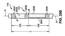
図示する実施形態では、送達カテーテルは、第1のプルワイヤ2035、第2のプルワイヤ2036、3つのリングまたはプルリング(すなわち第1のリング2037、第2のリング2038、第3のリング2039)、第1のスパイン2040、および第2のスパイン2041を備える、2プルワイヤシステムを有する。図20Aは、送達カテーテル114の遠位セクション117の端面図を示す。図20Cは、線C−Cにより示される平面に沿った図20Aの送達カテーテル114の断面図である。図20Bは、線B−Bにより示される平面に沿った送達カテーテル114の断面図である。図20Dは、図20Aの線D−Dにより示される平面に沿った送達カテーテル114の断面図を示す。図20Eは、図20Aの線E−Eにより示される平面に沿った送達カテーテル114の断面図により示される平面に沿った図である。図21Aおよび図21Bは、図15および図16の図と同様の、それぞれ部分作動状態および完全作動状態にある送達カテーテル114の概略斜視図である。図22Aは、送達カテーテル114の部分図である。図22B〜図22Dは、図22Aにおいてそれぞれ線B−B、C−C、D−Dにより示される平面に沿った送達カテーテルの断面図を示す。図23は、送達カテーテル114用の2プルワイヤシステムの側面図である。例えば上記で論じた実施形態のいずれかに示されるような、種々の様式で展開および使用される他の送達カテーテルおよびシースが、同様の2プルワイヤシステムと共に構成されることも可能である。図示する実施形態は、リング2037、2038、2039およびスパイン2040、2041を有する送達カテーテル114を示すが、送達カテーテル114は、任意の個数のリングおよび/またはスパインを有して、あるいはリングまたはスパインを有さずに構成され得る点を理解されたい。 In the illustrated embodiment, the delivery catheter comprises a
図示する実施形態では、送達カテーテル114は、2つの可撓性セクション115、116を備える遠位領域117を有する。図20Cを参照すると、第1の可撓性セクション115は、第1のリング2037と第2のリング2038との間に延在する。第1のプルワイヤ2035が、連結点Aにて第1のリング2037に対して装着され、第1のプルワイヤ2035の作動により、第1の可撓性セクション115は、図11および図12に示す略円形構成を形成する。図20C、図20D、図22A、および図22Bを参照すると、オプションのスパイン2040が、第1のリング2037と第2のリング2038との間において連結される。スパイン2040は、可撓性チューブ2030よりも高い剛直性の材料から作製され、したがって第1のプルワイヤ2035が作動される場合にリング2037、2038間の圧縮などの動きを抑制するように構成される。スパイン2040は、例えば可撓性チューブよりも高い剛直性のステンレス鋼、プラスチック、または任意の他の適切な材料などから作製され得る。可撓性チューブ2030は、例えばニチノール、鋼、および/またはプラスチック、あるいは送達カテーテル114が曲げ構成(例えば図12に示す曲げ構成)へと動かされるのを可能にする任意の他の適切な材料または材料の組合せなどから作製され得る。いくつかの実施形態では、スパイン2040に関するショアD硬度と可撓性チューブ2030のショアD硬度との比率は、約3:1である。いくつかの実施形態では、可撓性チューブ2030に対するスパイン2040のショアD硬度の比率は、約2:1〜約4:1の間、約2.5:1〜約3.5:1の間など、約1.5:1〜約5:1の間である。代替的な実施形態では、可撓性チューブ2030に対するスパイン2040のショアD硬度の比率は、5:1超または1.5:1未満である。 In the embodiment shown, the
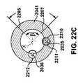
図示する実施形態では、スパイン2040は、スパイン2040の中心が第1のプルワイヤ2035から周方向に約180度だけオフセットされるように、第1のプルワイヤ2035の実質的に対向側に配設される。スパイン2040の中心は、第1のプルワイヤ2035から周方向に、約80度〜約100度の間、約85度〜約95度の間など、約70度〜約110度の間だけオフセットされることが可能である。図22Bを参照すると、スパイン2040の幅(角度θにより定義される)は、図11および図12に示す屈曲構成へと送達カテーテル114を動かし得る任意の適切な幅となり得る。いくつかの実施形態では、スパイン2040のエッジ2201、2203間の角度θは、約60度〜約120度の間、約75度〜約105度の間、約85度〜約95度の間、約90度など、約45度〜約135度の間であることが可能である。より大きな角度θは、より小さな角度θに比べてリング2037、2038の動きの制約においてより高い制御をスパイン2040が有することを可能にする。スパイン2041は、例えばニチノール、鋼、および/またはプラスチック、あるいは任意の他の適切な材料または材料の組合せなどから作製され得る。 In the illustrated embodiment, the
図20Bを参照すると、第2の可撓性セクション116は、第2のリング2038と第3のリング2039との間に延在する。第2のプルワイヤ2036は、連結点Bにて第2のリング2038に対して装着され、第2のプルワイヤ2036の作動により、第2の可撓性セクション116は、図11および図12において示されるより鋭角的な屈曲部を形成する。図20B、図20E、図22A、および図22Cを参照すると、任意のスパイン2041が、第2のリング2038と第3のリング2039との間に連結される。スパイン2041は、可撓性チューブ2030よりも高い剛直性の材料から作製され、したがって第2のプルワイヤ2036が作動されるとリング2038、2039間の動きを制約するように構成される。スパイン2041は、例えばステンレス鋼、プラスチック、または可撓性チューブよりも剛直性の高い任意の他の適切な材料から作製され得る。可撓性チューブ2030は、例えばニチノール、鋼、および/またはプラスチック、あるいは送達カテーテル114が曲げ構成(例えば図12に示す曲げ構成など)へと動くのを可能にする任意の他の適切な材料または材料の組合せなどから作製され得る。いくつかの実施形態では、スパイン2041に関するショアD硬度と可撓性チューブ2030のショアD硬度とのの比率は、約3:1である。いくつかの実施形態では、可撓性チューブ2030に対するスパイン2041のショアD硬度の比率は、約2:1〜約4:1の間、約2.5:1〜約3.5:1の間など、約1.5:1〜約5:1の間である。代替的な実施形態では、可撓性チューブ2030に対するスパイン2041のショアD硬度の比率は、5:1超または1.5:1未満である。 Referring to FIG. 20B, the second
図示する実施形態では、スパイン2041は、スパイン2041の中心が、第2のプルワイヤ2036から周方向に約180度だけオフセットされるように、第2のプルワイヤ2036の実質的に対向側に配設される。スパイン2041の中心は、第2のプルワイヤ2036から周方向に、約80度〜約100度の間、約85度〜約95度の間など、約70度〜約110度の間だけオフセットされることが可能である。図22Cを参照すると、スパイン2041の幅(角度βにより定義される)は、図12に示す屈曲構成へと送達カテーテル114を動かし得る任意の適切な幅となり得る。いくつかの実施形態では、スパイン2041のエッジ2205、2207間の角度βは、約60度〜約120度の間、約75度〜約105度の間、約85度〜約95度の間、約90度など、約45度〜約135度の間であることが可能である。より大きな角度βは、より小さな角度βに比べてリング2037、2038の動きの制約においてより高い制御をスパイン2040が有する(すなわちより高い剛直性を付加する)ことを可能にする。 In the illustrated embodiment, the
図20D〜図20Eを参照すると、送達カテーテル114は、アンカリングデバイス1を通して送達するのに十分なサイズ設定をされたルーメン2032を備え、このルーメン2032は、第1のプルワイヤ2035および第2のプルワイヤ2036が図12に示す屈曲構成へと送達カテーテル114を動かすために作動される場合に、アンカリングデバイス1を送達するのに十分なサイズ設定状態に留まる。ルーメン2032は、例えば卵形断面、円形断面を有することが可能であり、またはアンカリングデバイス1が通り効果的に前進され得る限りにおいては任意の他の適切な形状を有する断面を有することが可能である。 20D-20E, the
第2のリング2038に対して第2のプルワイヤ2036を装着するための連結点Bは、第1のリング2037に対して第1のプルワイヤ2035を装着するための連結点Aに対して近位に位置決めされ、例えば遠位領域117の周囲において約90度などだけ周方向にオフセットされ得る。90度のオフセットにより、この領域中に2つの直角屈曲部が許容され、この場合に、セクション115、116のそれぞれの曲率半径および関節動作方向は、相互に異なり相互に別個であることが可能である。いくつかの実施形態では、セクション115、116は、例えば約75度〜約105度の間、約80度〜約100度の間、約85度〜約95度の間など、約65度〜約115度の間などだけ周方向にオフセットされ得る。図20Cおよび図20Eを参照すると、いくつかの実施形態では、ワイヤ2035、2036は、これらのワイヤが送達カテーテルの中心を貫通して延在する軸Xに対して実質的に平行になるように、送達カテーテル114の長さLに沿って延在する。この実施形態では、ワイヤ2035、2036は、ワイヤ2035、2036間の角度αが約75度〜約105度の間、約80度〜約100度の間、約85度〜約95度の間、約90度など、約65度〜約115度の間となるように、周方向にオフセットされる。 Connection point B for attaching
図9A〜図9Uおよび図20A〜図23を参照すると、実際に、ガイドシース20が、例えば図示する位置にて天然弁輪(例えば僧帽弁輪または三尖弁輪)の近傍に配置されると、遠位領域117(およびいくつかの実施形態では近位セクション2034の一部分)を含む送達カテーテル114の遠位領域が、ガイドシース20の遠位開口から外へ前進される。この場合に、ガイドシース20から延出する送達カテーテル114の部分は、心房(例えば左心房または右心房)内に位置決めされ得る一方で、いくつかの場合では、送達カテーテル114の一部は、送達カテーテル114が作動構成へと、または事前に部分的に作動されている場合には完全作動構成もしくは最終作動構成へと調節される前に、天然弁(例えば天然僧帽弁)または天然弁の交連を貫通して心室(例えば左心室または右心室)内へと若干(例えば1〜5mmまたはそれ未満)延在することも可能である。次いで、プルワイヤ2035、2036は、遠位領域117を作動させ、送達カテーテル114の遠位部分にてセクション115、116中における2つの屈曲部の作動を実現するために、張力をかけられ得る。例えば、あるシーケンスでは、図21Aに示すように、第2のプルワイヤ2036は、初めにセクション116を屈曲し、天然弁輪(例えば天然僧帽弁輪)に対して実質的に平面状となるようにセクション116の遠位の送達カテーテル114の部分を配置するために、張力をかけられ得る。次いで、図21Bに示すように、第1のプルワイヤ2035は、セクション115の湾曲が天然弁輪の平面(例えば僧帽平面)に対して実質的に平面状または平行になるように、丸み作動状態または湾曲作動状態へとセクション115を屈曲するように張力をかけられ得る。他の実施形態では、プルワイヤ2035、2036は、作動中に患者の解剖学的構造体の周囲にまたはそれに対して適切かつ安全に誘導するために種々の量および/または順序において部分的にまたは完全に張力をかけられ得る。例えば、プルワイヤ2035、2036は、図9A〜図9Uにおいて送達カテーテル64が移動されるのと同一の様式で送達カテーテル114を移動させるように張力をかけられ得る。プルワイヤまたはプルワイヤシステムの作動は、所望の位置および/または配向へとカテーテルの遠位領域および遠位先端部を送るために、送達デバイスまたはその一部分(例えば送達カテーテルもしくは送達シース)にトルク付与することまたは回転させることと組み合わせて利用され得る。 Referring to FIGS. 9A-9U and FIGS. 20A-23, indeed, the
例えば、送達カテーテル114の遠位領域117が、所望の構成へと完全に作動または湾曲された後に(図21Bに示すように)、アセンブリは、次いで送達カテーテル114の先端部が天然弁の交連にて(例えば天然僧帽弁の交連A3P3にてなど)位置合わせされるようにトルク付与され回転され得る。送達カテーテル114は、送達カテーテル114の遠位先端部が交連に向かっておよび/または交連内に送られるように、トルク付与および回転され得る。次いで、送達カテーテル114のさらなる回転により、交連に向かうおよび/または交連内への送達カテーテル114の遠位先端部の周方向前進、および/またはそれによる下方向からより水平または平行な(もしくはより下方向ではない)方向への方向転換(例えばアンカリングデバイスの第1の端部が送達カテーテルから外に押し出された後などに)が促進され、それによりアンカリングデバイスの端部は、アンカリングデバイス1が、例えば心室内の腱索、乳頭筋、および/または他の特徴部などの天然解剖学的構造体の外部(例えば天然僧帽解剖学的構造体の外部)の周囲に輪を形成され得るまたは位置決めされ得るように、弁輪の上面への挿入、衝突、もしくは押圧後に望ましくない上向きになることがなくなり得る。 For example, after the
図22A〜図22Dおよび図23を参照すると、いくつかの実施形態では、送達カテーテル114は、第1のプルワイヤ2035を収容するための第1の導管2210(例えばチューブ、スリーブ等)と、第2のプルワイヤ2036を収容するための第2の導管2212とを備える。図示する実施形態では、導管2210、2212は、可撓性チューブ2030のライナ2215および内方表面2216により少なくとも部分的に画定される。いくつかの実施形態では、導管2210、2212は、任意の他の適切な形状をとり得る。いくつかの実施形態では、導管は、プルワイヤ2035、2036を収容するために使用されない。近位セクション140の設計およびプルワイヤ2035、2036の構成は、プルワイヤ135、136が作動される場合に送達カテーテル114を介した急動防止効果または屈曲防止効果をもたらす。これにより、経中隔屈曲部を介した送達カテーテル114の完全なトルク性の維持が可能となり得る。また、これは、遠位領域117の作動形状が、送達中のトルク付与または回転の最中により効果的に保持または維持されることを助長し得る。いくつかの実施形態では、送達カテーテル114は、第1のプルワイヤ2035が第1の曲げセクション115に到達するまで第1のプルワイヤ2035の周囲に延在する第1のコイルスリーブ2211と、第2のプルワイヤ2036が第2の曲げセクション116に到達するまで第2のプルワイヤ2036の周囲に延在する第2のコイルスリーブ2213とを備える。コイルスリーブ2211、2213は、急動防止効果または屈曲防止効果をもたらし、送達カテーテル114の完全なトルク性を維持するように構成される。 With reference to FIGS. 22A-22D and FIG. 23, in some embodiments, the
送達カテーテル114からの送達デバイス2の展開(および任意には心室内の解剖学的構造体の周囲における送達カテーテル114の動き)は、アンカリングデバイス1内の捕えられた解剖学的構造体を収束または捕捉する役割を果たす。いくつかの実施形態では、送達カテーテル114の遠位領域117は、左心室内の腱および他の特徴部の周囲の所望の位置まで移動され、第1のプルワイヤ135は、丸みセクション115の曲率半径を縮小するために、ならびに丸みセクション115の中心を貫通しさらに天然弁輪の中心に向かって通過する腱および他の僧帽解剖学的構造体を締め収束するために、張力をかけられる。左心室内の僧帽解剖学的構造体のかかる径方向締めまたは収束は、例えばアンカリングデバイス1が収束された腱および他の特徴部の周囲において前進されるのをより容易にすることなどによって、以降におけるアンカリングデバイス1のさらにより強固な送達を助長するのを補助し得る。 Deployment of the
送達カテーテルが、天然解剖学的構造体を捕えるために心室内で使用される場合には、送達カテーテル114が、左心室内の腱および他の所望の解剖学的構造体の周囲に十分に位置決めされた後に、アンカリングデバイス1は、送達カテーテル114の遠位開口から外へと前進され得る。丸みセクション115の湾曲は、アンカリングデバイス1の最終湾曲と実質的に同様になるように形成され得るため、丸みセクション115の湾曲形状により送達カテーテル114からのアンカリングデバイス1のより平滑かつより容易な押出しが助長され得る。さらに、左心室内の所望の僧帽解剖学的構造体の少なくとも一部の周囲において遠位領域117で最初に輪を形成することにより、予め捕えられている同解剖学的構造体の外部および周囲へのアンカリングデバイス1のより容易な送達が促進される。アンカリングデバイス1の心室部分が、左心室内の所望の位置まで前進されると、アンカリングデバイス1の心房部分は、例えば送達カテーテル114の後方への軸方向並進移動によってなど上記で論じた様々な方法の中の1つと同様の様式で送達カテーテル114から放出され得る。また、送達カテーテル114のかかる並進移動は、送達カテーテル114自体が左心室から出て左心房内に戻り後退するのを補助し得る。次いで、アンカリングデバイス1が所望位置まで完全に送達および移動された後に、プルワイヤ2035、2036中の張力が解放され、送達カテーテル114は直線化され、ガイドシース20を通り戻るように後退され得る。その後、THVまたは他の人工弁が、以前に論じたのと同様にアンカリングデバイス1へと前進され、アンカリングデバイス1内で拡張され得る。 If the delivery catheter is used in the ventricle to capture a native anatomical structure, the
いくつかの実施形態では(例えば本願で説明される送達カテーテルに関する実施形態のいずれか)、送達カテーテル114が所望の位置および配向へと前進および操縦される場合に、ガイドシース20または患者の解剖学的構造体に対して損傷が与えられる可能性を防止または軽減するために、非外傷性先端部118が遠位領域117の端部にさらに形成され得る。非外傷性先端部118は、丸いまたは他の非外傷性形状で形成された遠位領域117の延長部であることが可能であり、あるいは例えば追加の編組層などの遠位領域117とは異なる材料から形成された、および/またはより低いデュロメータの材料から作製された追加層であることが可能である。 In some embodiments (eg, any of the delivery catheter embodiments described herein), the
任意には、アンカリングデバイスまたはドッキングデバイスは、例えばアンカリングデバイスまたはドッキングデバイスの全体または一部分(例えば前縁巻線および/または機能巻線)の周囲に嵌着するPTFEスリーブなどの低摩擦スリーブをさらに備えることが可能である。例えば、この低摩擦スリーブは、アンカリングデバイス(またはその一部分)が中に嵌入するルーメンを備えることが可能である。低摩擦スリーブは、低摩擦性と、アンカリングデバイスの表面に比べて天然組織に対してアブレーションまたは損傷を与える可能性がより低いこととにより、低摩擦スリーブが送達カテーテルから出る場合に定位置へとアンカリングデバイスを摺動および/または回転させることをより容易にし得る。低摩擦スリーブは、アンカリングデバイスが天然弁内の定位置におかれた後に、例えば組織内部成長を促進するように構成された部分(多孔性表面領域、編組表面領域、大表面領域等)であり得るまたはそれらを備え得るアンカリングデバイスの表面を露出させるためなどに、除去可能であることが可能である(例えばプッシャおよびアンカリングデバイスを定位置に保持しつつスリーブを近位方向に引くことにより)。 Optionally, the anchoring or docking device may include a low friction sleeve, such as a PTFE sleeve that fits around all or a portion of the anchoring or docking device (eg, a leading edge winding and / or a functional winding). Further provisions are possible. For example, the low friction sleeve can include a lumen into which the anchoring device (or a portion thereof) fits. The low-friction sleeve has a low friction and is less likely to ablate or damage natural tissue compared to the surface of the anchoring device, so that the low-friction sleeve will stay in place as it exits the delivery catheter. And / or allowing the anchoring device to slide and / or rotate. After the anchoring device is in place in the natural valve, the low-friction sleeve is, for example, in a portion configured to promote tissue ingrowth (porous surface region, braided surface region, large surface region, etc.). It can be removable, such as to expose the surface of an anchoring device that may or may comprise them (eg, pulling the sleeve proximally while holding the pusher and anchoring device in place) By).
本明細書において説明される送達カテーテル構成は、アンカリングデバイスの正確な位置決めおよび展開を可能にする例の実施形態を提供する。しかし、いくつかの例では、アンカリングデバイスの後退または部分的後退が、例えば天然弁にてアンカリングデバイスを再位置決めするためにまたは植込み部位からアンカリングデバイスを除去するためになど、アンカリングデバイスの展開の最中または後の任意の段階において依然として必要である可能性がある。以下の実施形態は、送達カテーテルから外にアンカリングデバイスを押し出す展開プッシャとの間でアンカリングデバイスまたはドッキングデバイスを着脱するために使用され得る様々なロックまたはロック−解除機構を説明する。例えば参照により本明細書に組み込まれる2017年9月20日に出願された米国特許仮出願第62/560,962号に記載されるものなどの他のロックまたはロッキング機構もまた可能である。アンカリングデバイスは、近位側部において、アンカリングデバイスを押す、引く、およびアンカリングデバイスから容易に取り外すことが可能なプッシャまたは他の機構に対して連結され得る。 The delivery catheter configurations described herein provide example embodiments that allow for accurate positioning and deployment of the anchoring device. However, in some instances, the retraction or partial retraction of the anchoring device is such that the anchoring device is repositioned, for example, at a natural valve or to remove the anchoring device from an implantation site. May still be required during or after deployment of any of these. The following embodiments describe various locking or unlocking mechanisms that can be used to attach and detach an anchoring or docking device with a deployment pusher that pushes the anchoring device out of the delivery catheter. Other locking or locking mechanisms are also possible, such as, for example, those described in US Provisional Application No. 62 / 560,962, filed September 20, 2017, which is incorporated herein by reference. The anchoring device may be coupled on the proximal side to a pusher or other mechanism that can push, pull, and easily remove the anchoring device from the anchoring device.
前出の例では、プッシャまたはプッシャツールの縫合糸またはラインは、アンカリングデバイスを保持しアンカリングデバイスの後退性および放出を可能にするために、アンカリングデバイスの端部の開口または目穴を貫通して通される。図17A〜図17Cは、一例のアンカリングデバイス81の近位端部82と、ボールロッカーまたはボールロッキング機構84との斜視図を示す。アンカリングデバイス81は、上述のアンカリングデバイス実施形態と同様のものであることが可能であるが、図17Aに示すように修正された近位端部82が追加される。アンカリングデバイス81のこの近位端部82は、ロッキングチューブを形成する細長チューブ構造体83を有し、ボールロッキング機構84は、プッシャ85(本明細書において必要に応じて変更を加えられる他のプッシャと同一または同様のものであることが可能である)と、ロッキングチューブ83と連携するプルワイヤ86とを備える。プッシャ85は、図17A〜図17Cにおいて破断図で示されるが、アンカリングデバイス81の展開中に送達カテーテルを貫通して延在するのに十分な長さであることが可能である可撓性チューブ87を備える。プルワイヤ86は、プッシャ85を貫通して延在し、プルワイヤ86がアンカリングデバイス81のロッキングチューブ83を通りやはり進むことを可能にする長さを有してプッシャ85の遠位端部を通り押し出され得る。プッシャ85は、遠位先端部88と、プッシャ先端部88に対して連結されたおよび/またはプッシャ先端部88から延在する短ワイヤ89とを有する。短ワイヤ89の遠位端部が、球体ボール90を備える。 In the example above, the suture or line of the pusher or pusher tool cuts through an opening or eye at the end of the anchoring device to hold the anchoring device and allow for retraction and release of the anchoring device. It is passed through. 17A-17C show perspective views of a
アンカリングデバイス81の近位端部82のロッキングチューブ83は、図17Bに示すように短ワイヤ89の球体ボール90を通して受けるようにサイズ設定される。ロッキングチューブ83は、アンカリングデバイス81の近位端部(送達中の配向において)に対して溶接または他の方法で固着され得る短チューブである。ロッキングチューブ83の内径は、球体ボール90の外径よりも若干大きく、そのためボール90はロッキングチューブ83を通過し得る。ロックまたはロッキング機構は、ロッキングチューブ83の内径、ボール90の直径、ならびに短ワイヤ89およびプルワイヤ86の他の部分の直径の相対直径を基礎とする。 The locking
ボール90が、ロッキングチューブ83の遠位端部を貫通しそこから外に出た後に、ロッキングは、ボール90がロッキングチューブ83を通り戻るおよびロッキングチューブ83から放出されるのを防止することによって達成され得る。これは、ロッキングチューブ83内にプルワイヤ86を挿入することによっても達成され得る。短ワイヤ89のより細い部分およびプルワイヤ86の両方が、図17C〜図17Dに示すようにロッキングチューブ83内に挿通および位置決めされる場合に、ボール90は、ロッキングチューブ83を通り戻るのを阻止され、それによりプッシャ85に対してアンカリングデバイス81をロックする。図17Dにおいて最もよく示すように、プルワイヤ86がロッキングチューブ83内に位置する場合に、プルワイヤ86は、短ワイヤ89がロッキングチューブ83のボア内のより中心の位置へと移動するのを阻止するため、それによりボール90は、ロッキングチューブ83と整列されロッキングチューブ83を通り後退して戻り出ることを防止される。したがって、ボール90は、プッシャ85がロッキングチューブ83から近位方向に引かれると、ロッキングチューブ83の遠位端部に対して当接する。このロック位置において、プッシャ85は、アンカリングデバイス81に対してロックされ、術中にアンカリングデバイス81をより正確に位置決めするためにアンカリングデバイス81を押すまたは引くことが可能となる。ロッキングチューブ83からプルワイヤ86を引き戻して出した場合にのみ、ボール90がロッキングチューブ83と整列されロッキングチューブ83から放出されるための、およびアンカリングデバイス81がプッシャ85からロック解除または連結解除されるための空き経路および十分な空間が得られる。一方で、アンカリングデバイス81をロック解除するためにプルワイヤ86を後退させるためには、ロッキング力が、機構がロックされる場合に荷重の殆どを受ける短ワイヤ89に主として依拠するため、わずかに比較的小さな引力のみが必要となる。 After the
また、プルワイヤ86は、ロッキングチューブ83から除去されるために短い距離のみの移動を必要とする。例えば、プッシャ85からのアンカリングデバイス81のロック解除は、ロッキングチューブ83からプルワイヤ86を除去するために、および球体ボール90を放出させ得るために、約10mmだけのプルワイヤ86の後退を伴うにすぎない場合がある。他の実施形態では、アンカリングデバイス81は、約7mm〜約13mmの間、約8mm〜約12mmの間、約9mm〜約11mmの間など、約6mm〜約14mmの間だけプルワイヤ86を後退させることによりプッシャ85からロック解除され得る。いくつかの実施形態では、アンカリングデバイス81は、6mm未満または14mm超だけプルワイヤ86を後退させることによりプッシャ85からロック解除され得る。図17A〜図17Dの実施形態は、強いロッキング力を実現し得る一方で、同時に構成要素同士を相互にロック解除し取り外すために小さな引力のみを必要とする、強固で信頼性の高いロッキング機構を実現する。 Also, the
使用時に、ボールロッキング機構84は、例えば図17Cに示すように植込み前にアンカリングデバイス81と組み付けられ得る。送達カテーテルの遠位セクションが、上記の図8、図9A〜図9U、および図10に関連して説明した技術の中の1つを利用して、例えば僧帽弁輪にてなど天然弁輪にまたはその付近に位置決めされた後に、プッシャ85は、アンカリングデバイス81を展開するために送達カテーテルにアンカリングデバイス81を押し通し得る。次いで、ユーザは、プッシャ85を使用して天然弁輪に位置するアンカリングデバイス81をさらに後退および/または前進させて、植込み部位にアンカリングデバイス81をさらに正確に位置決めすることができる。アンカリングデバイス81が正確に位置決めされると、プルワイヤ86は、図17Bに示すようにロッキングチューブ83から後退されることが可能となり、次いで球体ボール90は、図17Aに示すようにロッキングチューブ83から後退および放出され、それによりボールロッキング機構84からアンカリングデバイス81を取り外すことが可能となる。次いで、プッシャ85は、植込み部位から除去され得る。 In use, the
図18A〜図18Cは、本発明の一実施形態によるアンカリングデバイス91の近位端部92とループロッキング機構94との斜視図を示す。アンカリングデバイス91は、上述のアンカリングデバイスの実施形態と同様のものであることが可能であるが、図18Aに示すように修正された近位端部92が追加される。アンカリングデバイス91の近位端部92は、細長近位穴またはスロット93を有し、ループロッキング機構94は、プッシャ95と、穴93と連携する側部ワイヤまたはプルワイヤ96とを備える。プッシャ95は、アンカリングデバイス91の展開中に送達カテーテルを通り延在するのに十分な長さであることが可能な可撓性チューブ97を備える。プルワイヤ96は、プッシャ95を貫通して延在し、以下でさらに詳細に論じるようにプルワイヤ96がワイヤループ99に係合することが可能となる長さでプッシャ95の遠位端部を通り押し出され得る。プッシャ95は、遠位先端部98と、プッシャ先端部98に対して連結されたおよび/またはプッシャ先端部98から延在するワイヤループ99とを有する。この実施形態では、ループ99は、プッシャ95の遠位先端部98から遠位方向に延在し、一般的にはプッシャ95の長手方向軸に対して垂直に延在する最遠位ループ部分を有する。この実施形態では、ワイヤループ99は、円筒状金属ワイヤなどのワイヤであるものとして図示されるが、本発明はそれに限定されない。また、他の実施形態では、ループ99は、例えばレーザ切断される平坦金属片または他の材料などから作製されることが可能であり、縫合糸を使用することにより形成されることが可能であり、またはアンカリングデバイス91のスロット93に進入し、プッシャ95に対してアンカリングデバイス91を固定するためにプルワイヤ96を受けることが可能な任意の他の適切な形状をとることが可能である。 18A-18C show perspective views of a
アンカリングデバイス91の近位端部92の穴93は、図18Bに示すようにワイヤループ99の端部を受けるようにサイズ設定される。ワイヤループ99が、穴93に通されると、ワイヤループ99の端部が、穴93の対向側部分を通過して延出し、ループ99は、この対向側部分から露出されるまたは突出する。ループ99は、プルワイヤ96が図18Cに示すようにループ99に挿通され得るのに十分な量だけ穴93の対向側部分から突出することが可能であるべきである。次いで、図18Cに示すようにループ99にプルワイヤ96を通過させることにより、アンカリングデバイス91は、プッシャ95が術中にアンカリングデバイス91をより正確に位置決めするためにアンカリングデバイス91を押すまたは引くことが可能となるロック位置に、プッシャ95を装着または係合させ得る。このロック位置で、プルワイヤ96は、ループ99を定位置にアンカリングし、ループ99が穴93から外に後退して戻されるのを防止する。ループ99から外にプルワイヤ96を引き戻すだけで、ループ99は、穴93から取り外され、アンカリングデバイス91は、プッシャ95からロック解除または連結解除されることが可能となる。一方で、アンカリングデバイス91をロック解除するためにプルワイヤ96を後退させるためには、ロッキング力が、機構がロックされる場合に荷重の殆どを受けるループ99に主として依拠するため、わずかに比較的小さな引力のみが必要となる。
ループロッキング機構94は、プッシャ95のループ99とプルワイヤ96との間の連携に依拠する。したがって、ループ99は、一方ではプルワイヤ96が通過するのに十分な余地を残すために挿入側の対向側の穴93の側部から突出するのに十分な長さまたは高さであり、他方においてはプッシャ95とアンカリングデバイス91との間の緊密な連結を維持するためにロック時に垂直方向変位を低減させるのに十分な短さである、長さを有する。したがって、図18A〜図18Cにおける実施形態もまた、構成要素同士をロック解除するためにプルワイヤ96による小さな引力および少量の後退のみを必要とする一方で、強力なロッキング力を実現し得る強固で信頼性の高いロッキング機構を提供する。例えば、プッシャ95からアンカリングデバイス91をロック解除することは、ループ99からプルワイヤ96を除去するためにおよびループ99が解放されるのを可能にするために約10mmだけプルワイヤ96を後退させることのみを伴い得る。他の実施形態では、アンカリングデバイス91は、約7mm〜約13mmの間、約8mm〜約12mmの間、約9mm〜約11mmの間など、約6mm〜約14mmの間だけプルワイヤ96を後退させることによりプッシャ95からロック解除され得る。いくつかの実施形態では、アンカリングデバイス91は、6mm未満または14mm超だけプルワイヤ96を後退させることによりプッシャ95からロック解除され得る。
使用時に、ループロッキング機構94は、図18Cに示すように術前にアンカリングデバイス91と組み付けられ得る。送達カテーテルの遠位セクションが、上記で図8、図9A〜図9U、および図10に関連して説明した技術の中の1つを利用して、例えば僧帽弁輪にてなど天然弁輪にまたはその付近に位置決めされた後に、プッシャ95は、アンカリングデバイス91を展開するために送達カテーテルにアンカリングデバイス91を押し通し得る。次いで、ユーザは、プッシャ95を使用して天然弁輪に位置するアンカリングデバイス91をさらに後退および/または前進させて、植込み部位にアンカリングデバイス91をさらに正確に位置決めすることができる。アンカリングデバイス91が正確に位置決めされると、プルワイヤ96は、図18Bに示すようにループ99から外に後退されることが可能となり、次いでループ99は、図18Aに示すように穴93から外に後退され、それによりループロッキング機構94からアンカリングデバイス91を取り外すことが可能となる。次いで、プッシャ95は、植込み部位から除去され得る。 In use, the
追加のプッシャおよび後退デバイス、ならびに他のシステム、デバイス、構成要素、方法等が、2016年12月20日に出願された米国特許仮出願第62/436,695号と、2017年9月20日に出願された米国特許仮出願第62/560,962号と、2017年12月15日に出願された「SYSTEMS AND MECHANISMS FOR DEPLOYING A DOCKING DEVICE FOR A REPLACEMENT HEART VALVE」と題する関連PCT特許出願(前述の仮出願における優先権を主張するもの)とにおいて開示されている。前述の出願はそれぞれ、参照によりその全体が本明細書に組み込まれる。前述の出願で開示される実施形態および方法はいずれも、必要に応じて変更を加えつつ、本願により開示される実施形態および方法のいずれと組み合わせることも可能である。 Additional pushers and retraction devices, as well as other systems, devices, components, methods, and the like, are disclosed in US Provisional Application No. 62 / 436,695, filed on December 20, 2016; U.S. Provisional Application No. 62 / 560,962, filed on Dec. 15, 2017, and a related PCT application entitled "SYSTEMS AND MECHANISMS FOR DEPLOYING A DOKING DEVICE FOR A REPLACEMENT HEART VALVE" filed on Dec. 15, 2017. Claiming priority in a provisional application). Each of the foregoing applications is incorporated herein by reference in its entirety. Any of the embodiments and methods disclosed in the aforementioned applications can be combined with any of the embodiments and methods disclosed by the present application, mutatis mutandis.
本明細書において説明されたシステムおよびデバイスの様々な操縦および制御は、自動化および/または電動化され得る。例えば、上述の制御部またはノブは、上記の制御部/ノブに関連して説明された動作を引き起こすボタンまたは電気入力であることが可能である。これは、ボタンまたは電気入力により作動されるモータ(例えば電気モータ、空気圧モータ、油圧モータ等)に対して動作パーツの一部またはすべてを連結する(直接的にまたは間接的に)ことにより実現され得る。例えば、モータは、作動された場合に、本明細書において説明される制御ワイヤまたはプルワイヤに張力をかけるまたは弛緩させることによりカテーテルの遠位領域を動かすように構成され得る。追加的にはまたは代替的には、モータは、作動された場合に、カテーテルに対して並進方向にまたは軸方向にプッシャを移動させることによりカテーテル内においておよび/またはカテーテル内外へとアンカリングデバイスまたはドッキングデバイスを移動させるように構成され得る。自動ストッパまたは防止手段が、例えばある特定の点を越えるような構成要素の移動を防止するためなどに、システム/デバイスおよび/または患者に対する損傷を防止するように内蔵され得る。 Various steering and control of the systems and devices described herein may be automated and / or motorized. For example, the controls or knobs described above can be buttons or electrical inputs that cause the operations described in connection with the controls / knobs above. This is achieved by coupling (directly or indirectly) some or all of the operating parts to a motor (eg an electric motor, a pneumatic motor, a hydraulic motor, etc.) that is actuated by a button or an electric input. obtain. For example, the motor, when activated, may be configured to move the distal region of the catheter by tensioning or relaxing the control or pull wires described herein. Additionally or alternatively, the motor, when activated, moves the pusher translationally or axially relative to the catheter to move the anchoring device into and / or out of the catheter. The docking device may be configured to move. Automatic stops or prevention means may be incorporated to prevent damage to the system / device and / or the patient, such as to prevent movement of components beyond certain points.
本明細書において説明されるデバイスおよび装置は、他の外科的手技およびアクセス箇所(例えば経心尖、開心等)と共に使用され得る点に留意されたい。また、本明細書において説明されるデバイス(例えば展開ツール)は、本明細書において説明される例とは異なる様々な他のタイプのアンカリングデバイスおよび/または人工デバイスとの組合せにおいて使用されることも可能である点に留意されたい。 Note that the devices and apparatus described herein can be used with other surgical procedures and access points (eg, transapical, open heart, etc.). Also, the devices described herein (eg, deployment tools) may be used in combination with various other types of anchoring and / or prosthetic devices that are different from the examples described herein. Note that this is also possible.
この説明においては、本開示の実施形態の特定の態様、利点、および新規の特徴が本明細書で説明される。これらの開示される方法、装置、およびシステムは、いかなる点においても限定的なものとして解釈されるべきではない。代わりに、本開示は、様々な開示される実施形態のあらゆる新規のかつ非自明な特徴および態様を、単独においてならびに様々な組合せおよび下位組合せにおいて対象とする。これらの方法、装置、およびシステムは、いずれかの特定の態様もしくは特徴またはそれらの組合せに限定されず、また開示される実施形態は、いずれかの1つまたは複数の特定の利点が存在すること、あるいは問題が解消されることを必須としない。一実施形態の特徴、要素、または構成要素は、本明細書においては他の実施形態へと組み合わされることが可能である。 In this description, certain aspects, advantages, and novel features of embodiments of the present disclosure are described herein. These disclosed methods, devices, and systems should not be construed as limiting in any way. Instead, this disclosure covers all novel and non-obvious features and aspects of the various disclosed embodiments, alone and in various combinations and sub-combinations. These methods, devices, and systems are not limited to any particular aspects or features, or combinations thereof, and the disclosed embodiments may exhibit any one or more of the specific advantages. Or, it is not essential that the problem be resolved. Features, elements, or components of one embodiment can be combined with other embodiments herein.
開示される実施形態のいくつかの動作が、提示の便宜性により特定の順序で説明されたが、この説明様式は、ある特定の順序が特定の表現により必要とされない限りはその順序変更を包含する点を理解されたい。例えば、順序立てて説明された動作が、いくつかの場合では順序変更または同時に実施され得る。さらに、簡略化のために、添付の図面は、開示された方法が他の方法との組合せにおいて利用され得る様々な様式を示さない場合がある。さらに、本説明は、時として開示される方法を説明するために「提供する」または「実現する」などの用語を使用する。これらの用語は、実施される実際の動作の高度に抽象的表現である。これらの用語に対応する実際の動作は、その特定の実装形態に応じて変化し得るものであり、当業者には容易に認識される。本明細書における様々な方法のステップは、組み合わせることが可能である。 Although some operations of the disclosed embodiments have been described in a particular order for convenience of presentation, this mode of description encompasses the reordering unless that particular order is required by the particular language. Please understand what you do. For example, operations described in order may be re-ordered or performed simultaneously in some cases. Further, for simplicity, the accompanying drawings may not show the various ways in which the disclosed method may be utilized in combination with other methods. Further, this description uses terms such as "provide" or "implement" to describe the sometimes disclosed method. These terms are highly abstract representations of the actual operations performed. The actual actions corresponding to these terms may vary depending on the particular implementation, and will be readily recognized by those skilled in the art. The steps of the various methods herein can be combined.
本開示の原理が適用され得る多数の可能な実施形態を鑑みて、図示する実施形態は、本発明の好ましい例にすぎず、本開示の範囲を限定するものとして解釈されるべきではない点を理解されたい。むしろ、本開示の範囲は、以下の特許請求の範囲により定義される。 In view of the number of possible embodiments to which the principles of the present disclosure may be applied, the depicted embodiments are merely preferred examples of the present invention and should not be construed as limiting the scope of the present disclosure. I want to be understood. Rather, the scope of the disclosure is defined by the following claims.
1 アンカリングデバイス、アンカリング部材、コイル
2 送達デバイス
5 心臓
10a 上方コイル
10b 上方コイル
12 コイル
12a 下方コイル
12b 下方コイル
20 外方シース、ガイドシース、経中隔シース、シース、外方ガイドシース
21 遠位端部部分、遠位端部
24 可撓性送達カテーテル、送達カテーテル
25 可撓性遠位セクション、遠位セクション
26 側部
27 側部
28 頂部
29 底部
30 レーザ切断シート、レーザ切断ファイル
31 側歯
32 側歯
33 上歯
34 側部溝、側部スロット、歯スロット
35 側部溝、側部スロット、歯スロット
36 上部溝、上部スロット
38 リンク
39 スリット
40 歯ライン
50 天然僧帽弁、天然僧帽弁輪
51 左心房
52 左心室
53 後尖、僧帽弁葉
54 前尖、僧帽弁葉
55 心房中隔、中隔
56 右心房
57 下大静脈
58 大動脈
59 三尖弁
60 人工経カテーテル心臓弁、THV
61 右心室
62 線維索、腱索、腱
63 大動脈弁
64 送達カテーテル、送達デバイス
65 遠位セクション、遠位端部
66 軽度湾曲部分
67 円形または湾曲状の平坦部分、円形/湾曲状平坦部分、平坦部分
68 巻線部
69 可撓性端部部分、可撓性端部
70 第1の作動ポイント
71 第2の作動ポイント
61
Claims (28)
Translated fromJapanese第1の端部を有する近位部分、第2の端部を有する遠位部分、および前記アンカリングデバイスを通過させるようにサイズ設定された前記第1の端部と前記第2の端部との間に延在するボアを備える可撓性チューブであって、前記遠位部分は、第1の曲げセクションおよび第2の曲げセクションを備える、可撓性チューブと、
前記可撓性チューブ内に少なくとも部分的に配設された第1のプルワイヤと、
前記可撓性チューブ内に少なくとも部分的に配設された第2のプルワイヤと
を備え、
前記第1のプルワイヤおよび前記第2のプルワイヤの作動により、前記可撓性チューブが第1の構成から第2の構成へと動かされ、
前記可撓性チューブが前記第2の構成にある場合に、前記第1の曲げセクションは第1の湾曲部分を形成し、前記第2の曲げセクションは湾曲平坦部分を形成する、送達カテーテル。A delivery catheter for delivering an anchoring device to a native valve of a patient's heart, wherein the anchoring device is configured to secure a prosthesis at the native valve.
A proximal portion having a first end, a distal portion having a second end, and the first end and the second end sized to pass through the anchoring device; A flexible tube comprising a bore extending between the flexible tube, the distal portion comprising a first bent section and a second bent section;
A first pull wire at least partially disposed within the flexible tube;
A second pull wire at least partially disposed within the flexible tube.
Actuation of the first pull wire and the second pull wire moves the flexible tube from a first configuration to a second configuration,
The delivery catheter, wherein the first bent section forms a first curved section and the second bent section forms a curved flat section when the flexible tube is in the second configuration.
前記心臓の心腔内に前記送達カテーテルを前進させるステップと、
前記送達カテーテルの第1の曲げセクションに第1の湾曲部分を形成するステップと、
前記送達カテーテルの第2の曲げセクションに湾曲平坦部分を形成するステップと、
前記天然弁の交連の方向に前記アンカリングデバイスを送達するために前記送達カテーテルの遠位開口を位置決めするステップと、
前記カテーテルを通して前記天然弁まで前記アンカリングデバイスを送達するステップと
を含む、方法。A method of using a delivery catheter to deliver an anchoring device to a natural valve of a patient's heart, comprising:
Advancing the delivery catheter into the heart chamber of the heart;
Forming a first curved portion in a first bent section of the delivery catheter;
Forming a curved flat in the second bent section of the delivery catheter;
Positioning a distal opening of the delivery catheter to deliver the anchoring device in the direction of the commissure of the natural valve;
Delivering the anchoring device through the catheter to the natural valve.
前記心臓まで前記送達カテーテルを前進させるステップと、
前記送達カテーテルの遠位開口が前記天然弁の交連の付近に位置決めされるように、前記天然弁輪の周囲に少なくとも部分的に前記送達カテーテルを曲げるステップと、
前記送達カテーテルの少なくとも一部分が前記天然弁輪を含む平面に対して実質的に平行になるように、前記送達カテーテルの延長部の高さまたは角度の少なくとも一方を調節するステップと
を含む、方法。A method of using a delivery catheter to deliver an anchoring device to a natural annulus of a patient's heart, wherein the anchoring device is configured to secure a prosthesis to the natural annulus.
Advancing the delivery catheter to the heart;
Bending the delivery catheter at least partially around the natural annulus such that the distal opening of the delivery catheter is positioned near the commissure of the natural valve;
Adjusting the height or angle of at least one of the extensions of the delivery catheter such that at least a portion of the delivery catheter is substantially parallel to a plane containing the native annulus.
Priority Applications (3)
| Application Number | Priority Date | Filing Date | Title |
|---|---|---|---|
| JP2022188505AJP7447226B2 (en) | 2016-12-16 | 2022-11-25 | Deployment systems, tools, and methods for delivering anchoring devices for prosthetic valves |
| JP2023134837AJP2023159316A (en) | 2016-12-16 | 2023-08-22 | Deployment systems, tools, and methods for delivering anchoring devices for prosthetic valves |
| JP2024028762AJP2024057066A (en) | 2016-12-16 | 2024-02-28 | DEPLOYMENT SYSTEMS, TOOLS, AND METHODS FOR DELIVERING ANCHORING DEVICES FOR PROSTHETIC VALVES - Patent application |
Applications Claiming Priority (3)
| Application Number | Priority Date | Filing Date | Title |
|---|---|---|---|
| US201662435563P | 2016-12-16 | 2016-12-16 | |
| US62/435,563 | 2016-12-16 | ||
| PCT/US2017/066854WO2018112429A1 (en) | 2016-12-16 | 2017-12-15 | Deployment systems, tools, and methods for delivering an anchoring device for a prosthetic valve |
Related Child Applications (2)
| Application Number | Title | Priority Date | Filing Date |
|---|---|---|---|
| JP2022188505ADivisionJP7447226B2 (en) | 2016-12-16 | 2022-11-25 | Deployment systems, tools, and methods for delivering anchoring devices for prosthetic valves |
| JP2023134837ADivisionJP2023159316A (en) | 2016-12-16 | 2023-08-22 | Deployment systems, tools, and methods for delivering anchoring devices for prosthetic valves |
Publications (2)
| Publication Number | Publication Date |
|---|---|
| JP2020501711Atrue JP2020501711A (en) | 2020-01-23 |
| JP7440263B2 JP7440263B2 (en) | 2024-02-28 |
Family
ID=62559822
Family Applications (4)
| Application Number | Title | Priority Date | Filing Date |
|---|---|---|---|
| JP2019531963AActiveJP7440263B2 (en) | 2016-12-16 | 2017-12-15 | Deployment systems, tools, and methods for delivering anchoring devices for prosthetic valves |
| JP2022188505AActiveJP7447226B2 (en) | 2016-12-16 | 2022-11-25 | Deployment systems, tools, and methods for delivering anchoring devices for prosthetic valves |
| JP2023134837APendingJP2023159316A (en) | 2016-12-16 | 2023-08-22 | Deployment systems, tools, and methods for delivering anchoring devices for prosthetic valves |
| JP2024028762APendingJP2024057066A (en) | 2016-12-16 | 2024-02-28 | DEPLOYMENT SYSTEMS, TOOLS, AND METHODS FOR DELIVERING ANCHORING DEVICES FOR PROSTHETIC VALVES - Patent application |
Family Applications After (3)
| Application Number | Title | Priority Date | Filing Date |
|---|---|---|---|
| JP2022188505AActiveJP7447226B2 (en) | 2016-12-16 | 2022-11-25 | Deployment systems, tools, and methods for delivering anchoring devices for prosthetic valves |
| JP2023134837APendingJP2023159316A (en) | 2016-12-16 | 2023-08-22 | Deployment systems, tools, and methods for delivering anchoring devices for prosthetic valves |
| JP2024028762APendingJP2024057066A (en) | 2016-12-16 | 2024-02-28 | DEPLOYMENT SYSTEMS, TOOLS, AND METHODS FOR DELIVERING ANCHORING DEVICES FOR PROSTHETIC VALVES - Patent application |
Country Status (16)
| Country | Link |
|---|---|
| US (3) | US10940000B2 (en) |
| EP (2) | EP3554424B1 (en) |
| JP (4) | JP7440263B2 (en) |
| CN (2) | CN110072492B (en) |
| AU (2) | AU2017378495B2 (en) |
| CA (1) | CA3046974A1 (en) |
| CR (1) | CR20190219A (en) |
| DK (1) | DK3554424T3 (en) |
| ES (1) | ES2941260T3 (en) |
| FI (1) | FI3554424T3 (en) |
| HR (1) | HRP20230241T1 (en) |
| HU (1) | HUE061376T2 (en) |
| PL (1) | PL3554424T3 (en) |
| PT (1) | PT3554424T (en) |
| SI (1) | SI3554424T1 (en) |
| WO (1) | WO2018112429A1 (en) |
Cited By (4)
| Publication number | Priority date | Publication date | Assignee | Title |
|---|---|---|---|---|
| JP2023531635A (en)* | 2020-06-17 | 2023-07-25 | パイプライン メディカル テクノロジーズ, インコーポレイテッド | Methods and apparatus for mitral valve chordae repair |
| JP2023535039A (en)* | 2020-07-23 | 2023-08-15 | エドワーズ ライフサイエンシーズ コーポレイション | Docking station for artificial heart valve |
| JP2023539300A (en)* | 2020-08-31 | 2023-09-13 | シファメド・ホールディングス・エルエルシー | prosthetic valve delivery system |
| JP2023548287A (en)* | 2020-11-04 | 2023-11-16 | エドワーズ ライフサイエンシーズ コーポレイション | Catheters for implants, catheters for medical procedures, and methods of use thereof |
Families Citing this family (147)
| Publication number | Priority date | Publication date | Assignee | Title |
|---|---|---|---|---|
| US8870950B2 (en) | 2009-12-08 | 2014-10-28 | Mitral Tech Ltd. | Rotation-based anchoring of an implant |
| US20110224785A1 (en) | 2010-03-10 | 2011-09-15 | Hacohen Gil | Prosthetic mitral valve with tissue anchors |
| US9763657B2 (en) | 2010-07-21 | 2017-09-19 | Mitraltech Ltd. | Techniques for percutaneous mitral valve replacement and sealing |
| US11653910B2 (en) | 2010-07-21 | 2023-05-23 | Cardiovalve Ltd. | Helical anchor implantation |
| US9308087B2 (en) | 2011-04-28 | 2016-04-12 | Neovasc Tiara Inc. | Sequentially deployed transcatheter mitral valve prosthesis |
| US9554897B2 (en) | 2011-04-28 | 2017-01-31 | Neovasc Tiara Inc. | Methods and apparatus for engaging a valve prosthesis with tissue |
| US10500038B1 (en) | 2011-05-20 | 2019-12-10 | Tel Hashomer Medical Research Infrastructure And Services Ltd. | Prosthetic mitral valve, and methods and devices for deploying the prosthetic mitral valve |
| WO2013021374A2 (en) | 2011-08-05 | 2013-02-14 | Mitraltech Ltd. | Techniques for percutaneous mitral valve replacement and sealing |
| US8852272B2 (en) | 2011-08-05 | 2014-10-07 | Mitraltech Ltd. | Techniques for percutaneous mitral valve replacement and sealing |
| EP2739214B1 (en) | 2011-08-05 | 2018-10-10 | Cardiovalve Ltd | Percutaneous mitral valve replacement and sealing |
| JP6219377B2 (en) | 2012-05-20 | 2017-10-25 | テル ハショマー メディカル リサーチ インフラストラクチャー アンド サーヴィシーズ リミテッド | Artificial mitral valve |
| US20150351906A1 (en) | 2013-01-24 | 2015-12-10 | Mitraltech Ltd. | Ventricularly-anchored prosthetic valves |
| EP3174502B1 (en) | 2014-07-30 | 2022-04-06 | Cardiovalve Ltd | Apparatus for implantation of an articulatable prosthetic valve |
| US9974651B2 (en) | 2015-02-05 | 2018-05-22 | Mitral Tech Ltd. | Prosthetic valve with axially-sliding frames |
| CN110141399B (en) | 2015-02-05 | 2021-07-27 | 卡迪尔维尔福股份有限公司 | Prosthetic valve with axial sliding frame |
| CA3007660A1 (en) | 2015-12-15 | 2017-06-22 | Neovasc Tiara Inc. | Transseptal delivery system |
| CN108778187A (en) | 2015-12-30 | 2018-11-09 | 管道医疗技术股份有限公司 | tethered mitral valve leaflets |
| US11833034B2 (en) | 2016-01-13 | 2023-12-05 | Shifamed Holdings, Llc | Prosthetic cardiac valve devices, systems, and methods |
| US10433952B2 (en) | 2016-01-29 | 2019-10-08 | Neovasc Tiara Inc. | Prosthetic valve for avoiding obstruction of outflow |
| US10531866B2 (en) | 2016-02-16 | 2020-01-14 | Cardiovalve Ltd. | Techniques for providing a replacement valve and transseptal communication |
| US20190231525A1 (en) | 2016-08-01 | 2019-08-01 | Mitraltech Ltd. | Minimally-invasive delivery systems |
| CA3031187A1 (en) | 2016-08-10 | 2018-02-15 | Cardiovalve Ltd. | Prosthetic valve with concentric frames |
| CA3042588A1 (en) | 2016-11-21 | 2018-05-24 | Neovasc Tiara Inc. | Methods and systems for rapid retraction of a transcatheter heart valve delivery system |
| WO2018098210A1 (en) | 2016-11-22 | 2018-05-31 | Synecor Llc | Guidewireless transseptal delivery system for therapeutic devices of the mitral valve |
| PT3554424T (en)* | 2016-12-16 | 2023-04-03 | Edwards Lifesciences Corp | Deployment systems, tools, and methods for delivering an anchoring device for a prosthetic valve |
| US11083580B2 (en) | 2016-12-30 | 2021-08-10 | Pipeline Medical Technologies, Inc. | Method of securing a leaflet anchor to a mitral valve leaflet |
| US9877833B1 (en) | 2016-12-30 | 2018-01-30 | Pipeline Medical Technologies, Inc. | Method and apparatus for transvascular implantation of neo chordae tendinae |
| US10925731B2 (en) | 2016-12-30 | 2021-02-23 | Pipeline Medical Technologies, Inc. | Method and apparatus for transvascular implantation of neo chordae tendinae |
| US10933214B2 (en)* | 2017-04-26 | 2021-03-02 | Biosense Webster (Israel) Ltd. | Method for producing a deflectable insertion tool |
| US10537426B2 (en) | 2017-08-03 | 2020-01-21 | Cardiovalve Ltd. | Prosthetic heart valve |
| US11793633B2 (en) | 2017-08-03 | 2023-10-24 | Cardiovalve Ltd. | Prosthetic heart valve |
| US12064347B2 (en) | 2017-08-03 | 2024-08-20 | Cardiovalve Ltd. | Prosthetic heart valve |
| US10575948B2 (en) | 2017-08-03 | 2020-03-03 | Cardiovalve Ltd. | Prosthetic heart valve |
| US10888421B2 (en) | 2017-09-19 | 2021-01-12 | Cardiovalve Ltd. | Prosthetic heart valve with pouch |
| US11246704B2 (en) | 2017-08-03 | 2022-02-15 | Cardiovalve Ltd. | Prosthetic heart valve |
| WO2019055154A2 (en) | 2017-08-06 | 2019-03-21 | Synecor Llc | Systems and methods for transseptal delivery of therapeutic devices of the heart |
| CA3073834A1 (en) | 2017-08-25 | 2019-02-28 | Neovasc Tiara Inc. | Sequentially deployed transcatheter mitral valve prosthesis |
| US20190083242A1 (en) | 2017-09-19 | 2019-03-21 | Cardiovalve Ltd. | Systems and methods for implanting a prosthetic valve within a native heart valve |
| EP3476366B1 (en)* | 2017-10-27 | 2020-12-16 | Medtentia International Ltd Oy | Annuloplasty implant |
| GB201720803D0 (en) | 2017-12-13 | 2018-01-24 | Mitraltech Ltd | Prosthetic Valve and delivery tool therefor |
| GB201800399D0 (en) | 2018-01-10 | 2018-02-21 | Mitraltech Ltd | Temperature-control during crimping of an implant |
| CA3088320A1 (en) | 2018-01-19 | 2019-07-25 | Edwards Lifesciences Corporation | Covered prosthetic heart valve |
| WO2019195860A2 (en) | 2018-04-04 | 2019-10-10 | Vdyne, Llc | Devices and methods for anchoring transcatheter heart valve |
| AU2019325548B2 (en) | 2018-08-21 | 2025-06-26 | Shifamed Holdings, Llc | Prosthetic cardiac valve devices, systems, and methods |
| US10595994B1 (en) | 2018-09-20 | 2020-03-24 | Vdyne, Llc | Side-delivered transcatheter heart valve replacement |
| US11278437B2 (en) | 2018-12-08 | 2022-03-22 | Vdyne, Inc. | Compression capable annular frames for side delivery of transcatheter heart valve replacement |
| US12186187B2 (en) | 2018-09-20 | 2025-01-07 | Vdyne, Inc. | Transcatheter deliverable prosthetic heart valves and methods of delivery |
| US11344413B2 (en) | 2018-09-20 | 2022-05-31 | Vdyne, Inc. | Transcatheter deliverable prosthetic heart valves and methods of delivery |
| US10321995B1 (en) | 2018-09-20 | 2019-06-18 | Vdyne, Llc | Orthogonally delivered transcatheter heart valve replacement |
| US11071627B2 (en) | 2018-10-18 | 2021-07-27 | Vdyne, Inc. | Orthogonally delivered transcatheter heart valve frame for valve in valve prosthesis |
| CN113260337A (en) | 2018-10-05 | 2021-08-13 | 施菲姆德控股有限责任公司 | Prosthetic heart valve devices, systems, and methods |
| CN113056302B (en) | 2018-10-19 | 2023-03-28 | 施菲姆德控股有限责任公司 | Adjustable medical device |
| US11109969B2 (en) | 2018-10-22 | 2021-09-07 | Vdyne, Inc. | Guidewire delivery of transcatheter heart valve |
| JP7128963B2 (en)* | 2018-10-25 | 2022-08-31 | キヤノン ユーエスエイ,インコーポレイテッド | Medical device with reflow trap anchor and method of use thereof |
| CN113271890B (en) | 2018-11-08 | 2024-08-30 | 内奥瓦斯克迪亚拉公司 | Ventricular deployment of transcatheter mitral valve prosthesis |
| JP7555919B2 (en) | 2018-11-14 | 2024-09-25 | シェバ インパクト リミテッド | Atrioventricular valve repair |
| CN113226223A (en)* | 2018-11-20 | 2021-08-06 | 爱德华兹生命科学公司 | Deployment tools and methods for delivering devices to native heart valves |
| JP2022513793A (en) | 2018-12-12 | 2022-02-09 | パイプライン メディカル テクノロジーズ, インコーポレイテッド | Methods and equipment for mitral valve chordae tendineae repair |
| US11253359B2 (en) | 2018-12-20 | 2022-02-22 | Vdyne, Inc. | Proximal tab for side-delivered transcatheter heart valves and methods of delivery |
| US10653522B1 (en) | 2018-12-20 | 2020-05-19 | Vdyne, Inc. | Proximal tab for side-delivered transcatheter heart valve prosthesis |
| CN111374800A (en)* | 2018-12-29 | 2020-07-07 | 杭州德晋医疗科技有限公司 | A valve ring retraction system |
| WO2020146842A1 (en) | 2019-01-10 | 2020-07-16 | Vdyne, Llc | Anchor hook for side-delivery transcatheter heart valve prosthesis |
| US11273032B2 (en) | 2019-01-26 | 2022-03-15 | Vdyne, Inc. | Collapsible inner flow control component for side-deliverable transcatheter heart valve prosthesis |
| US11185409B2 (en) | 2019-01-26 | 2021-11-30 | Vdyne, Inc. | Collapsible inner flow control component for side-delivered transcatheter heart valve prosthesis |
| US11135421B2 (en) | 2019-02-07 | 2021-10-05 | Synecor Llc | Conduit for transseptal passage of devices to the aorta |
| SG11202108429PA (en)* | 2019-02-20 | 2021-09-29 | Edwards Lifesciences Corp | Counterflexing steerable catheter for transcatheter heart valve therapy |
| WO2020181154A2 (en) | 2019-03-05 | 2020-09-10 | Vdyne, Inc. | Tricuspid regurgitation control devices for orthogonal transcatheter heart valve prosthesis |
| CA3132873A1 (en) | 2019-03-08 | 2020-09-17 | Neovasc Tiara Inc. | Retrievable prosthesis delivery system |
| US11076956B2 (en) | 2019-03-14 | 2021-08-03 | Vdyne, Inc. | Proximal, distal, and anterior anchoring tabs for side-delivered transcatheter mitral valve prosthesis |
| US11173027B2 (en) | 2019-03-14 | 2021-11-16 | Vdyne, Inc. | Side-deliverable transcatheter prosthetic valves and methods for delivering and anchoring the same |
| US10631983B1 (en) | 2019-03-14 | 2020-04-28 | Vdyne, Inc. | Distal subannular anchoring tab for side-delivered transcatheter valve prosthesis |
| US10758346B1 (en) | 2019-03-14 | 2020-09-01 | Vdyne, Inc. | A2 clip for side-delivered transcatheter mitral valve prosthesis |
| EP3941391B1 (en)* | 2019-03-19 | 2024-12-04 | Shifamed Holdings, LLC | Prosthetic cardiac valve devices, systems |
| CA3135753C (en) | 2019-04-01 | 2023-10-24 | Neovasc Tiara Inc. | Controllably deployable prosthetic valve |
| US11491006B2 (en) | 2019-04-10 | 2022-11-08 | Neovasc Tiara Inc. | Prosthetic valve with natural blood flow |
| CA3138875A1 (en) | 2019-05-04 | 2020-11-12 | Vdyne, Inc. | Cinch device and method for deployment of a side-delivered prosthetic heart valve in a native annulus |
| US11779742B2 (en) | 2019-05-20 | 2023-10-10 | Neovasc Tiara Inc. | Introducer with hemostasis mechanism |
| CN113891695A (en)* | 2019-06-07 | 2022-01-04 | 爱德华兹生命科学公司 | Systems, devices, and methods for treating heart valves |
| JP7520897B2 (en) | 2019-06-20 | 2024-07-23 | ニオバスク ティアラ インコーポレイテッド | Thin prosthetic mitral valve |
| CN113993572B (en) | 2019-07-25 | 2024-08-23 | 创新心有限公司 | Device for arranging a guide wire around a heart valve |
| CA3149527A1 (en) | 2019-08-14 | 2021-02-18 | Innovalve Bio Medical Ltd. | Atrioventricular valve replacement |
| EP4480458A3 (en) | 2019-08-20 | 2025-04-09 | Vdyne, Inc. | Delivery devices for side-deliverable transcatheter prosthetic valves |
| CN120531525A (en) | 2019-08-26 | 2025-08-26 | 维迪内股份有限公司 | Laterally deliverable transcatheter prosthetic valve and method for its delivery and anchoring |
| WO2021038560A1 (en)* | 2019-08-28 | 2021-03-04 | Valtech Cardio, Ltd. | Low-profile steerable catheter |
| CN110742664A (en)* | 2019-11-22 | 2020-02-04 | 茵络(无锡)医疗器械有限公司 | Anchor delivery device |
| EP4079367A4 (en)* | 2019-12-17 | 2024-01-10 | Lifetech Scientific (Shenzhen) Co., Ltd. | Delivery sheath and medical device |
| WO2021140398A2 (en)* | 2020-01-10 | 2021-07-15 | Valtech Cardio, Ltd. | Catheter ultrasound devices and methods for assessing targeted tissue |
| US11234813B2 (en) | 2020-01-17 | 2022-02-01 | Vdyne, Inc. | Ventricular stability elements for side-deliverable prosthetic heart valves and methods of delivery |
| CA3170042A1 (en)* | 2020-02-04 | 2021-08-12 | Cardiovalve Ltd. | Support-guided steering |
| EP4114313B1 (en)* | 2020-03-03 | 2025-10-01 | Shifamed Holdings, LLC | Prosthetic cardiac valve devices, systems |
| WO2021207545A1 (en)* | 2020-04-08 | 2021-10-14 | Shifamed Holdings, Llc | Valve delivery system |
| CN111467083B (en)* | 2020-05-11 | 2025-05-16 | 上海纽脉医疗科技有限公司 | A delivery tube of a tissue clamping device and a valve repair device |
| EP4096760A1 (en)* | 2020-05-19 | 2022-12-07 | Edwards Lifesciences Innovation (Israel) Ltd. | Steerable catheter |
| CN111568607B (en)* | 2020-06-17 | 2025-06-13 | 上海纽脉医疗科技股份有限公司 | A pipe fitting for a leaflet catching ring and a leaflet catching ring |
| WO2022046678A1 (en)* | 2020-08-31 | 2022-03-03 | Shifamed Holdings, Llc | Interface for prosthetic cardiac valve and delivery systems |
| WO2022047274A1 (en)* | 2020-08-31 | 2022-03-03 | Shifamed Holdings, Llc | Prosthetic cardiac valve delivery systems and methods |
| MX2023004528A (en) | 2020-10-23 | 2023-05-08 | Edwards Lifesciences Corp | Prosthetic valve docking device. |
| AU2021376271A1 (en)* | 2020-11-04 | 2023-06-08 | Edwards Lifesciences Corporation | Systems, tools, and methods for delivering implants and catheters for a prosthetic valve |
| CA3199758A1 (en) | 2020-11-11 | 2022-05-19 | Edwards Lifesciences Corporation | Prosthetic heart valves with sealing frames to reduce paravalvular leakage |
| CN114469450A (en) | 2020-11-13 | 2022-05-13 | 爱德华兹生命科学公司 | Apparatus and method for controlling fluid flow in a delivery device |
| US12357459B2 (en) | 2020-12-03 | 2025-07-15 | Cardiovalve Ltd. | Transluminal delivery system |
| US12329635B2 (en) | 2020-12-04 | 2025-06-17 | Shifamed Holdings, Llc | Flared prosthetic cardiac valve delivery devices and systems |
| EP4281012A1 (en) | 2021-01-19 | 2023-11-29 | Edwards Lifesciences Corporation | Delivery apparatus and methods for prosthetic valve docking devices |
| US12201521B2 (en) | 2021-03-22 | 2025-01-21 | Shifamed Holdings, Llc | Anchor position verification for prosthetic cardiac valve devices |
| CA3216190A1 (en)* | 2021-04-14 | 2022-10-20 | Edwards Lifesciences Corporation | Delivery systems for implants |
| US20240238089A1 (en)* | 2021-05-05 | 2024-07-18 | Innovalve Bio Medical Ltd. | Delivery device |
| WO2023034936A2 (en)* | 2021-09-01 | 2023-03-09 | Shifamed Holdings, Llc | Guide catheter for prosthetic cardiac valve delivery systems |
| EP4404874A4 (en)* | 2021-09-22 | 2025-08-13 | Shifamed Holdings Llc | HEART VALVE RELEASE HOLDER |
| CN115957046A (en) | 2021-10-08 | 2023-04-14 | 爱德华兹生命科学公司 | Prosthetic valve docking device |
| WO2023091254A1 (en) | 2021-11-19 | 2023-05-25 | Edwards Lifesciences Corporation | Prosthetic valve docking device |
| CN116172640A (en)* | 2021-11-26 | 2023-05-30 | 先健科技(深圳)有限公司 | Push cable, push system, heat treatment method and preparation method of push cable |
| CN114376769A (en)* | 2022-01-24 | 2022-04-22 | 上海臻亿医疗科技有限公司 | delivery catheter |
| CN220309243U (en) | 2022-03-17 | 2024-01-09 | 爱德华兹生命科学公司 | Delivery device and delivery assembly |
| WO2023200925A1 (en) | 2022-04-14 | 2023-10-19 | Edwards Lifesciences Corporation | Delivery apparatus for a docking device |
| WO2023240244A2 (en)* | 2022-06-09 | 2023-12-14 | Shifamed Holdings, Llc | Prosthetic heart valve delivery system and method |
| EP4539783A1 (en) | 2022-06-16 | 2025-04-23 | Edwards Lifesciences Corporation | Fluid sealing mechanism for a catheter |
| TW202412718A (en) | 2022-06-20 | 2024-04-01 | 美商愛德華生命科學公司 | Catheter shaft for an implant delivery apparatus |
| KR20250025730A (en) | 2022-06-21 | 2025-02-24 | 에드워즈 라이프사이언시스 코포레이션 | Quick-release suture mechanism and suture locking assembly comprising same |
| CN222815912U (en) | 2022-06-21 | 2025-05-02 | 爱德华兹生命科学公司 | A delivery device for a prosthetic implant |
| JP2025521553A (en) | 2022-06-23 | 2025-07-10 | エドワーズ ライフサイエンシーズ コーポレイション | Implant delivery device with telescopic shaft |
| CN115192258A (en)* | 2022-06-27 | 2022-10-18 | 瀚芯医疗科技(深圳)有限公司 | Conveying system |
| CN115300184A (en)* | 2022-08-10 | 2022-11-08 | 上海汇禾医疗科技有限公司 | Heart valve positioning device, artificial heart valve system, implantation system and method |
| EP4580549A1 (en) | 2022-09-01 | 2025-07-09 | Edwards Lifesciences Corporation | Prosthetic valve docking devices |
| EP4608339A1 (en) | 2022-10-25 | 2025-09-03 | Edwards Lifesciences Corporation | Guide catheter for an implant delivery apparatus |
| WO2024118363A1 (en) | 2022-11-28 | 2024-06-06 | Edwards Lifesciences Corporation | Implantable devices and sealing members and associated methods |
| CN116570401A (en)* | 2022-12-01 | 2023-08-11 | 上海微创心通医疗科技有限公司 | Conveying assembly and conveying system |
| WO2024129448A1 (en) | 2022-12-16 | 2024-06-20 | Edwards Lifesciences Corporation | Prosthetic valve docking device |
| WO2024158666A1 (en) | 2023-01-25 | 2024-08-02 | Edwards Lifesciences Corporation | Prosthetic medical device delivery system |
| WO2024163319A1 (en) | 2023-01-30 | 2024-08-08 | Edwards Lifesciences Corporation | Seals for delivery apparatuses |
| WO2024186557A1 (en) | 2023-03-05 | 2024-09-12 | Edwards Lifesciences Corporation | Hemostatic valve for catheter applications |
| WO2024186723A1 (en) | 2023-03-05 | 2024-09-12 | Edwards Lifesciences Corporation | Prosthetic medical device delivery apparatus |
| WO2024191576A1 (en) | 2023-03-13 | 2024-09-19 | Edwards Lifesciences Corporation | Prosthetic medical device delivery assembly |
| WO2024192160A1 (en) | 2023-03-14 | 2024-09-19 | Edwards Lifesciences Corporation | Stabilizer clamp apparatus for use with implant delivery apparatus |
| WO2024220192A1 (en) | 2023-04-18 | 2024-10-24 | Edwards Lifesciences Corporation | Prosthetic valve docking device |
| WO2024258844A1 (en) | 2023-06-12 | 2024-12-19 | Edwards Lifesciences Corporation | Lumen liner seals and associated methods for prosthetic implant delivery apparatuses |
| WO2024258839A1 (en) | 2023-06-12 | 2024-12-19 | Edwards Lifesciences Corporation | Balloon catheters for prosthetic implants |
| WO2025019176A1 (en) | 2023-07-19 | 2025-01-23 | Edwards Lifesciences Corporation | Prosthetic valve docking device |
| WO2025019171A1 (en) | 2023-07-19 | 2025-01-23 | Edwards Lifesciences Corporation | Prosthetic valve docking device |
| WO2025019174A1 (en) | 2023-07-19 | 2025-01-23 | Edwards Lifesciences Corporation | Prosthetic valve docketing device |
| WO2025019179A1 (en)* | 2023-07-20 | 2025-01-23 | Edwards Lifesciences Corporation | Atraumatic tips for prosthetic implant delivery apparatus |
| CN117017575B (en)* | 2023-10-09 | 2024-01-23 | 杭州德晋医疗科技有限公司 | Catheter assembly and system for encircling subvalvular tissue |
| WO2025090407A1 (en) | 2023-10-23 | 2025-05-01 | Edwards Lifesciences Corporation | Prosthetic valve docking device |
| WO2025101566A1 (en) | 2023-11-10 | 2025-05-15 | Edwards Lifesciences Corporation | Delivery systems for prosthetic heart valves |
| WO2025117321A1 (en)* | 2023-11-27 | 2025-06-05 | Edwards Lifesciences Corporation | Transcatheter heart valve delivery system solutions |
| WO2025128418A1 (en)* | 2023-12-15 | 2025-06-19 | Edwards Lifesciences Corporation | Systems, devices, and methods for treating heart valves |
| WO2025136696A1 (en) | 2023-12-21 | 2025-06-26 | Edwards Lifesciences Corporation | Prosthetic valve leaflet attachment |
| WO2025136695A1 (en) | 2023-12-21 | 2025-06-26 | Edwards Lifesciences Corporation | Guide catheter for an implant delivery apparatus |
Citations (4)
| Publication number | Priority date | Publication date | Assignee | Title |
|---|---|---|---|---|
| US5329923A (en)* | 1991-02-15 | 1994-07-19 | Lundquist Ingemar H | Torquable catheter |
| US20020082585A1 (en)* | 1999-06-15 | 2002-06-27 | Sean Carroll | Defined deflection structure |
| US20140046250A1 (en)* | 2011-03-15 | 2014-02-13 | Barts And The London Nhs Trust | Steerable element for use in surgery |
| US20140309661A1 (en)* | 2011-11-08 | 2014-10-16 | Valtech Cardio, Ltd. | Controlled steering functionality for implant-delivery tool |
Family Cites Families (148)
| Publication number | Priority date | Publication date | Assignee | Title |
|---|---|---|---|---|
| US4035849A (en) | 1975-11-17 | 1977-07-19 | William W. Angell | Heart valve stent and process for preparing a stented heart valve prosthesis |
| DE3368321D1 (en) | 1982-04-21 | 1987-01-22 | Haigh Chadwick Ltd | Cyclically weighing bulk solid material |
| US4592340A (en) | 1984-05-02 | 1986-06-03 | Boyles Paul W | Artificial catheter means |
| US4994077A (en) | 1989-04-21 | 1991-02-19 | Dobben Richard L | Artificial heart valve for implantation in a blood vessel |
| US5059177A (en) | 1990-04-19 | 1991-10-22 | Cordis Corporation | Triple lumen balloon catheter |
| US5411552A (en) | 1990-05-18 | 1995-05-02 | Andersen; Henning R. | Valve prothesis for implantation in the body and a catheter for implanting such valve prothesis |
| DK124690D0 (en) | 1990-05-18 | 1990-05-18 | Henning Rud Andersen | FAT PROTECTION FOR IMPLEMENTATION IN THE BODY FOR REPLACEMENT OF NATURAL FLEET AND CATS FOR USE IN IMPLEMENTING A SUCH FAT PROTECTION |
| US5350397A (en)* | 1992-11-13 | 1994-09-27 | Target Therapeutics, Inc. | Axially detachable embolic coil assembly |
| US5728068A (en) | 1994-06-14 | 1998-03-17 | Cordis Corporation | Multi-purpose balloon catheter |
| US5554185A (en) | 1994-07-18 | 1996-09-10 | Block; Peter C. | Inflatable prosthetic cardiovascular valve for percutaneous transluminal implantation of same |
| US5599305A (en) | 1994-10-24 | 1997-02-04 | Cardiovascular Concepts, Inc. | Large-diameter introducer sheath having hemostasis valve and removable steering mechanism |
| US5639274A (en) | 1995-06-02 | 1997-06-17 | Fischell; Robert E. | Integrated catheter system for balloon angioplasty and stent delivery |
| DE19532846A1 (en) | 1995-09-06 | 1997-03-13 | Georg Dr Berg | Valve for use in heart |
| DE19534112A1 (en)* | 1995-09-14 | 1997-03-20 | Wolf Gmbh Richard | Endoscopic instrument with steerable distal end |
| US5591195A (en) | 1995-10-30 | 1997-01-07 | Taheri; Syde | Apparatus and method for engrafting a blood vessel |
| GB9614950D0 (en) | 1996-07-16 | 1996-09-04 | Anson Medical Ltd | A ductus stent and delivery catheter |
| US6217585B1 (en) | 1996-08-16 | 2001-04-17 | Converge Medical, Inc. | Mechanical stent and graft delivery system |
| JP3968444B2 (en) | 1996-08-23 | 2007-08-29 | ボストン サイエンティフィック サイムド,インコーポレイテッド | Stent delivery mechanism with stent fixation device |
| US5968068A (en) | 1996-09-12 | 1999-10-19 | Baxter International Inc. | Endovascular delivery system |
| EP0850607A1 (en) | 1996-12-31 | 1998-07-01 | Cordis Corporation | Valve prosthesis for implantation in body channels |
| US6527979B2 (en) | 1999-08-27 | 2003-03-04 | Corazon Technologies, Inc. | Catheter systems and methods for their use in the treatment of calcified vascular occlusions |
| DE19907646A1 (en) | 1999-02-23 | 2000-08-24 | Georg Berg | Valve for blood vessels uses flap holders and counterpart holders on stent to latch together in place and all channeled for guide wire. |
| US6858034B1 (en) | 1999-05-20 | 2005-02-22 | Scimed Life Systems, Inc. | Stent delivery system for prevention of kinking, and method of loading and using same |
| FR2800984B1 (en) | 1999-11-17 | 2001-12-14 | Jacques Seguin | DEVICE FOR REPLACING A HEART VALVE PERCUTANEOUSLY |
| FR2815844B1 (en) | 2000-10-31 | 2003-01-17 | Jacques Seguin | TUBULAR SUPPORT FOR THE PERCUTANEOUS POSITIONING OF A REPLACEMENT HEART VALVE |
| US7018406B2 (en) | 1999-11-17 | 2006-03-28 | Corevalve Sa | Prosthetic valve for transluminal delivery |
| US6458153B1 (en) | 1999-12-31 | 2002-10-01 | Abps Venture One, Ltd. | Endoluminal cardiac and venous valve prostheses and methods of manufacture and delivery thereof |
| MXPA02007426A (en) | 2000-01-31 | 2003-10-14 | Cook Biotech Inc | Stent valves and uses of same. |
| US7296577B2 (en)* | 2000-01-31 | 2007-11-20 | Edwards Lifescience Ag | Transluminal mitral annuloplasty with active anchoring |
| US20050070999A1 (en) | 2000-02-02 | 2005-03-31 | Spence Paul A. | Heart valve repair apparatus and methods |
| US6797002B2 (en) | 2000-02-02 | 2004-09-28 | Paul A. Spence | Heart valve repair apparatus and methods |
| US6454799B1 (en) | 2000-04-06 | 2002-09-24 | Edwards Lifesciences Corporation | Minimally-invasive heart valves and methods of use |
| US20050043757A1 (en) | 2000-06-12 | 2005-02-24 | Michael Arad | Medical devices formed from shape memory alloys displaying a stress-retained martensitic state and method for use thereof |
| US7077861B2 (en) | 2000-07-06 | 2006-07-18 | Medtentia Ab | Annuloplasty instrument |
| US6419696B1 (en) | 2000-07-06 | 2002-07-16 | Paul A. Spence | Annuloplasty devices and related heart valve repair methods |
| WO2002022054A1 (en) | 2000-09-12 | 2002-03-21 | Gabbay S | Valvular prosthesis and method of using same |
| US7510572B2 (en) | 2000-09-12 | 2009-03-31 | Shlomo Gabbay | Implantation system for delivery of a heart valve prosthesis |
| US6461382B1 (en) | 2000-09-22 | 2002-10-08 | Edwards Lifesciences Corporation | Flexible heart valve having moveable commissures |
| EP1341487B1 (en) | 2000-12-15 | 2005-11-23 | Angiomed GmbH & Co. Medizintechnik KG | Stent with valve |
| EP1355590B1 (en)* | 2001-01-30 | 2008-12-10 | Edwards Lifesciences AG | Medical system for remodeling an extravascular tissue structure |
| US6733525B2 (en) | 2001-03-23 | 2004-05-11 | Edwards Lifesciences Corporation | Rolled minimally-invasive heart valves and methods of use |
| US7556646B2 (en) | 2001-09-13 | 2009-07-07 | Edwards Lifesciences Corporation | Methods and apparatuses for deploying minimally-invasive heart valves |
| US7374571B2 (en) | 2001-03-23 | 2008-05-20 | Edwards Lifesciences Corporation | Rolled minimally-invasive heart valves and methods of manufacture |
| US7037334B1 (en) | 2001-04-24 | 2006-05-02 | Mitralign, Inc. | Method and apparatus for catheter-based annuloplasty using local plications |
| EP1432369B1 (en) | 2001-08-31 | 2008-02-27 | Mitral Interventions | Apparatus for valve repair |
| US6893460B2 (en) | 2001-10-11 | 2005-05-17 | Percutaneous Valve Technologies Inc. | Implantable prosthetic valve |
| WO2003077730A2 (en) | 2002-03-11 | 2003-09-25 | Wardle John L | Surgical coils and methods of deploying |
| US6797001B2 (en) | 2002-03-11 | 2004-09-28 | Cardiac Dimensions, Inc. | Device, assembly and method for mitral valve repair |
| US7101395B2 (en) | 2002-06-12 | 2006-09-05 | Mitral Interventions, Inc. | Method and apparatus for tissue connection |
| DE60334122D1 (en)* | 2002-07-25 | 2010-10-21 | Boston Scient Ltd | MEDICAL DEVICE FOR NAVIGATING THROUGH ANATOMY |
| WO2004018031A2 (en)* | 2002-08-22 | 2004-03-04 | William A. Cook Australia Pty. Ltd. | Guide wire |
| US7137184B2 (en) | 2002-09-20 | 2006-11-21 | Edwards Lifesciences Corporation | Continuous heart valve support frame and method of manufacture |
| US20050119735A1 (en) | 2002-10-21 | 2005-06-02 | Spence Paul A. | Tissue fastening systems and methods utilizing magnetic guidance |
| US7485143B2 (en) | 2002-11-15 | 2009-02-03 | Abbott Cardiovascular Systems Inc. | Apparatuses and methods for heart valve repair |
| JP4685630B2 (en)* | 2002-11-25 | 2011-05-18 | エドワーズ ライフサイエンシーズ アクチェンゲゼルシャフト | Method and apparatus for remodeling extravascular tissue structure |
| JP2004180764A (en) | 2002-11-29 | 2004-07-02 | Tohoku Techno Arch Co Ltd | Active tubule |
| US7399315B2 (en) | 2003-03-18 | 2008-07-15 | Edwards Lifescience Corporation | Minimally-invasive heart valve with cusp positioners |
| AU2004233848B2 (en) | 2003-04-24 | 2010-03-04 | Cook Medical Technologies Llc | Artificial valve prosthesis with improved flow dynamics |
| JP2004351005A (en) | 2003-05-29 | 2004-12-16 | Japan Science & Technology Agency | Bending tube and method of manufacturing the same |
| US7553324B2 (en) | 2003-10-14 | 2009-06-30 | Xtent, Inc. | Fixed stent delivery devices and methods |
| US7004176B2 (en) | 2003-10-17 | 2006-02-28 | Edwards Lifesciences Ag | Heart valve leaflet locator |
| US20050137691A1 (en) | 2003-12-23 | 2005-06-23 | Sadra Medical | Two piece heart valve and anchor |
| US7311730B2 (en) | 2004-02-13 | 2007-12-25 | Shlomo Gabbay | Support apparatus and heart valve prosthesis for sutureless implantation |
| CA2813136A1 (en) | 2004-02-27 | 2005-09-15 | Aortx, Inc. | Prosthetic heart valve delivery systems and methods |
| US7993397B2 (en) | 2004-04-05 | 2011-08-09 | Edwards Lifesciences Ag | Remotely adjustable coronary sinus implant |
| BRPI0510107A (en) | 2004-04-23 | 2007-09-25 | 3F Therapeutics Inc | implantable protein valve |
| US7704277B2 (en) | 2004-09-14 | 2010-04-27 | Edwards Lifesciences Ag | Device and method for treatment of heart valve regurgitation |
| CN102247225B (en) | 2005-02-28 | 2015-07-22 | 梅德坦提亚国际有限公司 | Device for improving the function of heart valve and kit |
| US8864823B2 (en) | 2005-03-25 | 2014-10-21 | StJude Medical, Cardiology Division, Inc. | Methods and apparatus for controlling the internal circumference of an anatomic orifice or lumen |
| SE531468C2 (en) | 2005-04-21 | 2009-04-14 | Edwards Lifesciences Ag | An apparatus for controlling blood flow |
| JP4912395B2 (en) | 2005-05-24 | 2012-04-11 | エドワーズ ライフサイエンシーズ コーポレイション | Rapid placement prosthetic heart valve |
| US7780723B2 (en) | 2005-06-13 | 2010-08-24 | Edwards Lifesciences Corporation | Heart valve delivery system |
| US20070027533A1 (en) | 2005-07-28 | 2007-02-01 | Medtronic Vascular, Inc. | Cardiac valve annulus restraining device |
| US8128691B2 (en) | 2005-09-07 | 2012-03-06 | Medtentia International Ltd. Oy | Device and method for improving the function of a heart valve |
| WO2007033360A2 (en) | 2005-09-14 | 2007-03-22 | Micardia Corporation | Left atrial balloon catheter |
| US8007509B2 (en)* | 2005-10-12 | 2011-08-30 | Boston Scientific Scimed, Inc. | Coil assemblies, components and methods |
| US8167932B2 (en) | 2005-10-18 | 2012-05-01 | Edwards Lifesciences Corporation | Heart valve delivery system with valve catheter |
| US8778017B2 (en) | 2005-10-26 | 2014-07-15 | Cardiosolutions, Inc. | Safety for mitral valve implant |
| US8449606B2 (en) | 2005-10-26 | 2013-05-28 | Cardiosolutions, Inc. | Balloon mitral spacer |
| US7785366B2 (en) | 2005-10-26 | 2010-08-31 | Maurer Christopher W | Mitral spacer |
| EP1959864B1 (en) | 2005-12-07 | 2018-03-07 | Medtronic, Inc. | Connection systems for two piece prosthetic heart valve assemblies |
| WO2007084508A2 (en) | 2006-01-13 | 2007-07-26 | Mirabilis Medica, Inc. | Apparatus for delivering high intensity focused ultrasound energy to a treatment site internal to a patient's body |
| US8147541B2 (en) | 2006-02-27 | 2012-04-03 | Aortx, Inc. | Methods and devices for delivery of prosthetic heart valves and other prosthetics |
| US20070225681A1 (en)* | 2006-03-21 | 2007-09-27 | Medtronic Vascular | Catheter Having a Selectively Formable Distal Section |
| US7737060B2 (en) | 2006-03-31 | 2010-06-15 | Boston Scientific Scimed, Inc. | Medical devices containing multi-component fibers |
| EP2540246B8 (en)* | 2006-05-12 | 2020-10-07 | Vytronus, Inc. | Device for ablating body tissue |
| US8449605B2 (en)* | 2006-06-28 | 2013-05-28 | Kardium Inc. | Method for anchoring a mitral valve |
| US8029556B2 (en) | 2006-10-04 | 2011-10-04 | Edwards Lifesciences Corporation | Method and apparatus for reshaping a ventricle |
| SE530568C2 (en) | 2006-11-13 | 2008-07-08 | Medtentia Ab | Device and method for improving the function of a heart valve |
| JP5593545B2 (en)* | 2006-12-06 | 2014-09-24 | メドトロニック シーブイ ルクセンブルク エス.アー.エール.エル. | System and method for transapical delivery of a self-expanding valve secured to an annulus |
| US20080208327A1 (en) | 2007-02-27 | 2008-08-28 | Rowe Stanton J | Method and apparatus for replacing a prosthetic valve |
| FR2915087B1 (en) | 2007-04-20 | 2021-11-26 | Corevalve Inc | IMPLANT FOR TREATMENT OF A HEART VALVE, IN PARTICULAR OF A MITRAL VALVE, EQUIPMENT INCLUDING THIS IMPLANT AND MATERIAL FOR PLACING THIS IMPLANT. |
| ES2627667T3 (en)* | 2007-05-18 | 2017-07-31 | Boston Scientific Limited | Hollow joint device that can be twisted |
| US20080294230A1 (en) | 2007-05-24 | 2008-11-27 | Cook Incorporated | Apparatus and methods for deploying self-expanding stents |
| WO2009026563A2 (en) | 2007-08-23 | 2009-02-26 | Direct Flow Medical, Inc. | Translumenally implantable heart valve with formed in place support |
| US8197464B2 (en) | 2007-10-19 | 2012-06-12 | Cordis Corporation | Deflecting guide catheter for use in a minimally invasive medical procedure for the treatment of mitral valve regurgitation |
| ES2781686T3 (en) | 2007-12-14 | 2020-09-04 | Edwards Lifesciences Corp | Leaflet Junction Frame for a Prosthetic Valve |
| US20090276040A1 (en) | 2008-05-01 | 2009-11-05 | Edwards Lifesciences Corporation | Device and method for replacing mitral valve |
| US9061119B2 (en) | 2008-05-09 | 2015-06-23 | Edwards Lifesciences Corporation | Low profile delivery system for transcatheter heart valve |
| US8323335B2 (en) | 2008-06-20 | 2012-12-04 | Edwards Lifesciences Corporation | Retaining mechanisms for prosthetic valves and methods for using |
| US8652202B2 (en) | 2008-08-22 | 2014-02-18 | Edwards Lifesciences Corporation | Prosthetic heart valve and delivery apparatus |
| EP2389218A4 (en)* | 2009-01-20 | 2012-06-13 | Guided Delivery Systems Inc | Diagnostic catheters, guide catheters, visualization devices and chord manipulation devices, and related kits and methods |
| CA2961053C (en) | 2009-04-15 | 2019-04-30 | Edwards Lifesciences Cardiaq Llc | Vascular implant and delivery system |
| NZ596179A (en) | 2009-04-29 | 2014-05-30 | Cleveland Clinic Foundation | Apparatus and method for replacing a diseased cardiac valve |
| CN102625670B (en)* | 2009-06-16 | 2015-07-15 | 核磁共振成像介入技术有限公司 | MRI-guided devices and MRI-guided interventional systems that can track and generate dynamic visualizations of the devices in near real time |
| AU2010266027B2 (en)* | 2009-06-24 | 2015-05-07 | Shifamed Holdings, Llc | Steerable medical delivery devices and methods of use |
| US8439970B2 (en) | 2009-07-14 | 2013-05-14 | Edwards Lifesciences Corporation | Transapical delivery system for heart valves |
| US10034748B2 (en) | 2009-09-18 | 2018-07-31 | The Regents Of The University Of California | Endovascular prosthetic heart valve replacement |
| US8377115B2 (en) | 2009-11-16 | 2013-02-19 | Medtronic Vascular, Inc. | Implantable valve prosthesis for treating venous valve insufficiency |
| HUE059497T2 (en) | 2010-03-05 | 2022-11-28 | Edwards Lifesciences Corp | Support structures for heart valve prosthesis |
| US8657872B2 (en) | 2010-07-19 | 2014-02-25 | Jacques Seguin | Cardiac valve repair system and methods of use |
| WO2012019052A2 (en) | 2010-08-04 | 2012-02-09 | Micardia Corporation | Percutaneous transcatheter repair of heart valves |
| DE102010034345A1 (en) | 2010-08-14 | 2012-02-16 | Richard Wolf Gmbh | Endoscopic instrument comprises handle and shaft which is provided with bent section, where tubular support body is arranged in shaft, and tubular support body is divided in segments |
| WO2012031141A2 (en) | 2010-09-01 | 2012-03-08 | Maurice Buchbinder | Cardiac valve support structure |
| WO2012033847A1 (en) | 2010-09-07 | 2012-03-15 | Spence Paul A | Cannula systems and methods |
| DK4233795T3 (en) | 2010-10-05 | 2024-08-26 | Edwards Lifesciences Corp | Prosthetic heart valve |
| KR101912960B1 (en)* | 2010-10-25 | 2018-10-29 | 메드트로닉 아르디언 룩셈부르크 에스에이알엘 | Catheter Appratuses having Multi-Electrode Arrays for Renal Neuromodulation and Associated Systems and Methods |
| US20120158021A1 (en)* | 2010-12-19 | 2012-06-21 | Mitralign, Inc. | Steerable guide catheter having preformed curved shape |
| US9155619B2 (en)* | 2011-02-25 | 2015-10-13 | Edwards Lifesciences Corporation | Prosthetic heart valve delivery apparatus |
| US9364326B2 (en) | 2011-06-29 | 2016-06-14 | Mitralix Ltd. | Heart valve repair devices and methods |
| US9078747B2 (en) | 2011-12-21 | 2015-07-14 | Edwards Lifesciences Corporation | Anchoring device for replacing or repairing a heart valve |
| EP2620125B1 (en) | 2012-01-24 | 2017-10-11 | Medtentia International Ltd Oy | An arrangement, a loop-shaped support, a prosthetic heart valve and a method of repairing or replacing a native heart valve |
| CA3095260C (en)* | 2012-01-31 | 2023-09-19 | Mitral Valve Technologies Sarl | Mitral valve docking devices, systems and methods |
| WO2013130641A1 (en) | 2012-02-29 | 2013-09-06 | Valcare, Inc. | Percutaneous annuloplasty system with anterior-posterior adjustment |
| CN103930044B (en)* | 2012-03-08 | 2016-05-18 | 奥林巴斯株式会社 | guide sheath and medical system |
| CA2872611C (en)* | 2012-05-16 | 2020-09-15 | Edwards Lifesciences Corporation | Systems and methods for placing a coapting member between valvular leaflets |
| EP3593740B1 (en) | 2012-06-20 | 2021-10-06 | Stryker Corporation | System for off-axis tissue manipulation |
| CN103764012B (en)* | 2012-06-22 | 2016-03-09 | 奥林巴斯株式会社 | Curved tubes, medical equipment |
| JP5607695B2 (en) | 2012-09-13 | 2014-10-15 | ファナック株式会社 | Machine tool thermal displacement compensation device |
| US10029073B2 (en)* | 2012-11-13 | 2018-07-24 | Abbott Cardiovascular Systems, Inc. | Steerable assembly for surgical catheter |
| EP4162902A1 (en) | 2012-11-21 | 2023-04-12 | Edwards Lifesciences Corporation | Retaining mechanisms for prosthetic heart valves |
| EP2770208B1 (en)* | 2013-02-20 | 2018-01-10 | Schukra Gerätebau GmbH | Adjusting device for a vehicle component |
| US9339271B2 (en)* | 2013-03-14 | 2016-05-17 | C.R. Bard, Inc. | Articulating surgical instruments |
| US10166100B2 (en) | 2013-03-15 | 2019-01-01 | Valcare, Inc. | Systems and methods for delivery of annuloplasty rings |
| EP2805695A1 (en) | 2013-05-21 | 2014-11-26 | Medtentia International Ltd Oy | Medical system for annuloplasty |
| CA3199859A1 (en) | 2013-08-12 | 2015-02-19 | Mitral Valve Technologies Sarl | Apparatus and methods for implanting a replacement heart valve |
| LT3545906T (en)* | 2013-08-14 | 2021-03-10 | Mitral Valve Technologies Sarl | Replacement heart valve apparatus |
| US9622863B2 (en) | 2013-11-22 | 2017-04-18 | Edwards Lifesciences Corporation | Aortic insufficiency repair device and method |
| EP3107494B1 (en) | 2014-02-18 | 2023-12-06 | HVR Cardio Oy | Medical device for a cardiac valve implant |
| SG11201606836TA (en) | 2014-02-20 | 2016-09-29 | Mitral Valve Technologies Sarl | Coiled anchor for supporting prosthetic heart valve, prosthetic heart valve, and deployment device |
| EP3552585B1 (en)* | 2014-04-17 | 2022-10-26 | Medtronic Vascular Galway | Hinged transcatheter prosthetic heart valve delivery system |
| US9700412B2 (en) | 2014-06-26 | 2017-07-11 | Mitralix Ltd. | Heart valve repair devices for placement in ventricle and delivery systems for implanting heart valve repair devices |
| JP2017527373A (en) | 2014-09-08 | 2017-09-21 | メドテンティア・インターナショナル・リミテッド・オサケユキチュアMedtentia International Ltd Oy | Annuloplasty implant |
| US10016272B2 (en) | 2014-09-12 | 2018-07-10 | Mitral Valve Technologies Sarl | Mitral repair and replacement devices and methods |
| CR20170245A (en)* | 2014-12-05 | 2017-09-14 | Edwards Lifesciences Corp | DIRIGIBLE CATETER WITH TRACTION CABLE |
| US10039637B2 (en) | 2015-02-11 | 2018-08-07 | Edwards Lifesciences Corporation | Heart valve docking devices and implanting methods |
| DE102016001196B4 (en) | 2016-02-03 | 2018-05-30 | Audi Ag | Circuit arrangement and electrical system for a motor vehicle |
| PT3554424T (en)* | 2016-12-16 | 2023-04-03 | Edwards Lifesciences Corp | Deployment systems, tools, and methods for delivering an anchoring device for a prosthetic valve |
- 2017
- 2017-12-15PTPT178800124Tpatent/PT3554424T/enunknown
- 2017-12-15CRCR20190219Apatent/CR20190219A/enunknown
- 2017-12-15ESES17880012Tpatent/ES2941260T3/enactiveActive
- 2017-12-15PLPL17880012.4Tpatent/PL3554424T3/enunknown
- 2017-12-15FIFIEP17880012.4Tpatent/FI3554424T3/enactive
- 2017-12-15AUAU2017378495Apatent/AU2017378495B2/enactiveActive
- 2017-12-15WOPCT/US2017/066854patent/WO2018112429A1/ennot_activeCeased
- 2017-12-15DKDK17880012.4Tpatent/DK3554424T3/enactive
- 2017-12-15CNCN201780077481.8Apatent/CN110072492B/enactiveActive
- 2017-12-15EPEP17880012.4Apatent/EP3554424B1/enactiveActive
- 2017-12-15JPJP2019531963Apatent/JP7440263B2/enactiveActive
- 2017-12-15CNCN202110563511.4Apatent/CN113288514B/enactiveActive
- 2017-12-15HUHUE17880012Apatent/HUE061376T2/enunknown
- 2017-12-15CACA3046974Apatent/CA3046974A1/enactivePending
- 2017-12-15HRHRP20230241TTpatent/HRP20230241T1/enunknown
- 2017-12-15SISI201731328Tpatent/SI3554424T1/enunknown
- 2017-12-15EPEP22216706.6Apatent/EP4218672A1/enactivePending
- 2018
- 2018-05-21USUS15/984,661patent/US10940000B2/enactiveActive
- 2018-11-07USUS16/182,955patent/US11382744B2/enactiveActive
- 2022
- 2022-06-29USUS17/809,869patent/US20220331101A1/enactivePending
- 2022-11-25JPJP2022188505Apatent/JP7447226B2/enactiveActive
- 2023
- 2023-02-07AUAU2023200645Apatent/AU2023200645B2/enactiveActive
- 2023-08-22JPJP2023134837Apatent/JP2023159316A/enactivePending
- 2024
- 2024-02-28JPJP2024028762Apatent/JP2024057066A/enactivePending
Patent Citations (4)
| Publication number | Priority date | Publication date | Assignee | Title |
|---|---|---|---|---|
| US5329923A (en)* | 1991-02-15 | 1994-07-19 | Lundquist Ingemar H | Torquable catheter |
| US20020082585A1 (en)* | 1999-06-15 | 2002-06-27 | Sean Carroll | Defined deflection structure |
| US20140046250A1 (en)* | 2011-03-15 | 2014-02-13 | Barts And The London Nhs Trust | Steerable element for use in surgery |
| US20140309661A1 (en)* | 2011-11-08 | 2014-10-16 | Valtech Cardio, Ltd. | Controlled steering functionality for implant-delivery tool |
Cited By (5)
| Publication number | Priority date | Publication date | Assignee | Title |
|---|---|---|---|---|
| JP2023531635A (en)* | 2020-06-17 | 2023-07-25 | パイプライン メディカル テクノロジーズ, インコーポレイテッド | Methods and apparatus for mitral valve chordae repair |
| JP7701390B2 (en) | 2020-06-17 | 2025-07-01 | パイプライン メディカル テクノロジーズ, インコーポレイテッド | Methods and devices for mitral valve chordae repair |
| JP2023535039A (en)* | 2020-07-23 | 2023-08-15 | エドワーズ ライフサイエンシーズ コーポレイション | Docking station for artificial heart valve |
| JP2023539300A (en)* | 2020-08-31 | 2023-09-13 | シファメド・ホールディングス・エルエルシー | prosthetic valve delivery system |
| JP2023548287A (en)* | 2020-11-04 | 2023-11-16 | エドワーズ ライフサイエンシーズ コーポレイション | Catheters for implants, catheters for medical procedures, and methods of use thereof |
Also Published As
| Publication number | Publication date |
|---|---|
| AU2023200645B2 (en) | 2024-09-12 |
| EP3554424B1 (en) | 2022-12-28 |
| EP4218672A1 (en) | 2023-08-02 |
| FI3554424T3 (en) | 2023-03-30 |
| CN110072492B (en) | 2021-06-11 |
| WO2018112429A1 (en) | 2018-06-21 |
| JP2024057066A (en) | 2024-04-23 |
| AU2017378495B2 (en) | 2022-11-24 |
| JP2023159316A (en) | 2023-10-31 |
| JP7447226B2 (en) | 2024-03-11 |
| PL3554424T3 (en) | 2023-05-08 |
| CN110072492A (en) | 2019-07-30 |
| AU2017378495A1 (en) | 2019-05-23 |
| US20220331101A1 (en) | 2022-10-20 |
| PT3554424T (en) | 2023-04-03 |
| ES2941260T3 (en) | 2023-05-19 |
| JP2023022180A (en) | 2023-02-14 |
| US20180318079A1 (en) | 2018-11-08 |
| DK3554424T3 (en) | 2023-03-13 |
| US11382744B2 (en) | 2022-07-12 |
| EP3554424A1 (en) | 2019-10-23 |
| CN113288514A (en) | 2021-08-24 |
| SI3554424T1 (en) | 2023-04-28 |
| CN113288514B (en) | 2024-12-24 |
| US10940000B2 (en) | 2021-03-09 |
| JP7440263B2 (en) | 2024-02-28 |
| CR20190219A (en) | 2019-09-30 |
| AU2023200645A1 (en) | 2023-03-09 |
| EP3554424A4 (en) | 2020-01-01 |
| HRP20230241T1 (en) | 2023-04-14 |
| HUE061376T2 (en) | 2023-06-28 |
| US20190070003A1 (en) | 2019-03-07 |
| CA3046974A1 (en) | 2018-06-21 |
Similar Documents
| Publication | Publication Date | Title |
|---|---|---|
| JP7447226B2 (en) | Deployment systems, tools, and methods for delivering anchoring devices for prosthetic valves | |
| US12295834B2 (en) | Delivery apparatuses for medical device implants | |
| US20230270551A1 (en) | Catheters for implants and medical procedures and methods of use thereof | |
| CN219354279U (en) | Delivery system and system for implants | |
| US20230270552A1 (en) | Systems, tools, and methods for delivering implants and catheters for a prosthetic valve | |
| US20210212825A1 (en) | Transcatheter valve leaflet replacement device, delivery, guiding and fixation system and method for same | |
| HK40058059A (en) | Deployment systems, tools, and methods for delivering an anchoring device for a prosthetic valve | |
| HK40012323A (en) | Deployment systems, tools, and methods for delivering an anchoring device for a prosthetic valve | |
| HK40012323B (en) | Deployment systems, tools, and methods for delivering an anchoring device for a prosthetic valve | |
| HK40016382B (en) | Deployment systems and tools for delivering an anchoring device for a prosthetic valve | |
| HK40016382A (en) | Deployment systems and tools for delivering an anchoring device for a prosthetic valve |
Legal Events
| Date | Code | Title | Description |
|---|---|---|---|
| A521 | Request for written amendment filed | Free format text:JAPANESE INTERMEDIATE CODE: A523 Effective date:20190827 | |
| A621 | Written request for application examination | Free format text:JAPANESE INTERMEDIATE CODE: A621 Effective date:20201202 | |
| A977 | Report on retrieval | Free format text:JAPANESE INTERMEDIATE CODE: A971007 Effective date:20211111 | |
| A131 | Notification of reasons for refusal | Free format text:JAPANESE INTERMEDIATE CODE: A131 Effective date:20211122 | |
| A601 | Written request for extension of time | Free format text:JAPANESE INTERMEDIATE CODE: A601 Effective date:20220221 | |
| A521 | Request for written amendment filed | Free format text:JAPANESE INTERMEDIATE CODE: A523 Effective date:20220523 | |
| A02 | Decision of refusal | Free format text:JAPANESE INTERMEDIATE CODE: A02 Effective date:20220725 | |
| C60 | Trial request (containing other claim documents, opposition documents) | Free format text:JAPANESE INTERMEDIATE CODE: C60 Effective date:20221125 | |
| C22 | Notice of designation (change) of administrative judge | Free format text:JAPANESE INTERMEDIATE CODE: C22 Effective date:20230313 | |
| C22 | Notice of designation (change) of administrative judge | Free format text:JAPANESE INTERMEDIATE CODE: C22 Effective date:20230424 | |
| A521 | Request for written amendment filed | Free format text:JAPANESE INTERMEDIATE CODE: A523 Effective date:20230822 | |
| A61 | First payment of annual fees (during grant procedure) | Free format text:JAPANESE INTERMEDIATE CODE: A61 Effective date:20240215 | |
| R150 | Certificate of patent or registration of utility model | Ref document number:7440263 Country of ref document:JP Free format text:JAPANESE INTERMEDIATE CODE: R150 |