JP2020201519A - Projector holder - Google Patents
Projector holderDownload PDFInfo
- Publication number
- JP2020201519A JP2020201519AJP2020160316AJP2020160316AJP2020201519AJP 2020201519 AJP2020201519 AJP 2020201519AJP 2020160316 AJP2020160316 AJP 2020160316AJP 2020160316 AJP2020160316 AJP 2020160316AJP 2020201519 AJP2020201519 AJP 2020201519A
- Authority
- JP
- Japan
- Prior art keywords
- projector
- holder
- flexible
- appendages
- configuration
- Prior art date
- Legal status (The legal status is an assumption and is not a legal conclusion. Google has not performed a legal analysis and makes no representation as to the accuracy of the status listed.)
- Granted
Links
Images


Classifications
- G—PHYSICS
- G03—PHOTOGRAPHY; CINEMATOGRAPHY; ANALOGOUS TECHNIQUES USING WAVES OTHER THAN OPTICAL WAVES; ELECTROGRAPHY; HOLOGRAPHY
- G03B—APPARATUS OR ARRANGEMENTS FOR TAKING PHOTOGRAPHS OR FOR PROJECTING OR VIEWING THEM; APPARATUS OR ARRANGEMENTS EMPLOYING ANALOGOUS TECHNIQUES USING WAVES OTHER THAN OPTICAL WAVES; ACCESSORIES THEREFOR
- G03B21/00—Projectors or projection-type viewers; Accessories therefor
- G03B21/14—Details
- G03B21/145—Housing details, e.g. position adjustments thereof
- F—MECHANICAL ENGINEERING; LIGHTING; HEATING; WEAPONS; BLASTING
- F16—ENGINEERING ELEMENTS AND UNITS; GENERAL MEASURES FOR PRODUCING AND MAINTAINING EFFECTIVE FUNCTIONING OF MACHINES OR INSTALLATIONS; THERMAL INSULATION IN GENERAL
- F16M—FRAMES, CASINGS OR BEDS OF ENGINES, MACHINES OR APPARATUS, NOT SPECIFIC TO ENGINES, MACHINES OR APPARATUS PROVIDED FOR ELSEWHERE; STANDS; SUPPORTS
- F16M13/00—Other supports for positioning apparatus or articles; Means for steadying hand-held apparatus or articles
- F16M13/02—Other supports for positioning apparatus or articles; Means for steadying hand-held apparatus or articles for supporting on, or attaching to, an object, e.g. tree, gate, window-frame, cycle
- F16M13/022—Other supports for positioning apparatus or articles; Means for steadying hand-held apparatus or articles for supporting on, or attaching to, an object, e.g. tree, gate, window-frame, cycle repositionable
- B—PERFORMING OPERATIONS; TRANSPORTING
- B29—WORKING OF PLASTICS; WORKING OF SUBSTANCES IN A PLASTIC STATE IN GENERAL
- B29C—SHAPING OR JOINING OF PLASTICS; SHAPING OF MATERIAL IN A PLASTIC STATE, NOT OTHERWISE PROVIDED FOR; AFTER-TREATMENT OF THE SHAPED PRODUCTS, e.g. REPAIRING
- B29C39/00—Shaping by casting, i.e. introducing the moulding material into a mould or between confining surfaces without significant moulding pressure; Apparatus therefor
- B29C39/02—Shaping by casting, i.e. introducing the moulding material into a mould or between confining surfaces without significant moulding pressure; Apparatus therefor for making articles of definite length, i.e. discrete articles
- B29C39/10—Shaping by casting, i.e. introducing the moulding material into a mould or between confining surfaces without significant moulding pressure; Apparatus therefor for making articles of definite length, i.e. discrete articles incorporating preformed parts or layers, e.g. casting around inserts or for coating articles
- F—MECHANICAL ENGINEERING; LIGHTING; HEATING; WEAPONS; BLASTING
- F16—ENGINEERING ELEMENTS AND UNITS; GENERAL MEASURES FOR PRODUCING AND MAINTAINING EFFECTIVE FUNCTIONING OF MACHINES OR INSTALLATIONS; THERMAL INSULATION IN GENERAL
- F16F—SPRINGS; SHOCK-ABSORBERS; MEANS FOR DAMPING VIBRATION
- F16F15/00—Suppression of vibrations in systems; Means or arrangements for avoiding or reducing out-of-balance forces, e.g. due to motion
- F16F15/02—Suppression of vibrations of non-rotating, e.g. reciprocating systems; Suppression of vibrations of rotating systems by use of members not moving with the rotating systems
- F16F15/04—Suppression of vibrations of non-rotating, e.g. reciprocating systems; Suppression of vibrations of rotating systems by use of members not moving with the rotating systems using elastic means
- F16F15/08—Suppression of vibrations of non-rotating, e.g. reciprocating systems; Suppression of vibrations of rotating systems by use of members not moving with the rotating systems using elastic means with rubber springs ; with springs made of rubber and metal
- F—MECHANICAL ENGINEERING; LIGHTING; HEATING; WEAPONS; BLASTING
- F16—ENGINEERING ELEMENTS AND UNITS; GENERAL MEASURES FOR PRODUCING AND MAINTAINING EFFECTIVE FUNCTIONING OF MACHINES OR INSTALLATIONS; THERMAL INSULATION IN GENERAL
- F16M—FRAMES, CASINGS OR BEDS OF ENGINES, MACHINES OR APPARATUS, NOT SPECIFIC TO ENGINES, MACHINES OR APPARATUS PROVIDED FOR ELSEWHERE; STANDS; SUPPORTS
- F16M11/00—Stands or trestles as supports for apparatus or articles placed thereon ; Stands for scientific apparatus such as gravitational force meters
- F16M11/20—Undercarriages with or without wheels
- F16M11/24—Undercarriages with or without wheels changeable in height or length of legs, also for transport only, e.g. by means of tubes screwed into each other
- F16M11/40—Undercarriages with or without wheels changeable in height or length of legs, also for transport only, e.g. by means of tubes screwed into each other by means of coilable or bendable legs or spiral shaped legs
- G—PHYSICS
- G03—PHOTOGRAPHY; CINEMATOGRAPHY; ANALOGOUS TECHNIQUES USING WAVES OTHER THAN OPTICAL WAVES; ELECTROGRAPHY; HOLOGRAPHY
- G03B—APPARATUS OR ARRANGEMENTS FOR TAKING PHOTOGRAPHS OR FOR PROJECTING OR VIEWING THEM; APPARATUS OR ARRANGEMENTS EMPLOYING ANALOGOUS TECHNIQUES USING WAVES OTHER THAN OPTICAL WAVES; ACCESSORIES THEREFOR
- G03B21/00—Projectors or projection-type viewers; Accessories therefor
- G03B21/14—Details
- G03B21/16—Cooling; Preventing overheating
- G—PHYSICS
- G03—PHOTOGRAPHY; CINEMATOGRAPHY; ANALOGOUS TECHNIQUES USING WAVES OTHER THAN OPTICAL WAVES; ELECTROGRAPHY; HOLOGRAPHY
- G03B—APPARATUS OR ARRANGEMENTS FOR TAKING PHOTOGRAPHS OR FOR PROJECTING OR VIEWING THEM; APPARATUS OR ARRANGEMENTS EMPLOYING ANALOGOUS TECHNIQUES USING WAVES OTHER THAN OPTICAL WAVES; ACCESSORIES THEREFOR
- G03B21/00—Projectors or projection-type viewers; Accessories therefor
- G03B21/54—Accessories
- G—PHYSICS
- G03—PHOTOGRAPHY; CINEMATOGRAPHY; ANALOGOUS TECHNIQUES USING WAVES OTHER THAN OPTICAL WAVES; ELECTROGRAPHY; HOLOGRAPHY
- G03B—APPARATUS OR ARRANGEMENTS FOR TAKING PHOTOGRAPHS OR FOR PROJECTING OR VIEWING THEM; APPARATUS OR ARRANGEMENTS EMPLOYING ANALOGOUS TECHNIQUES USING WAVES OTHER THAN OPTICAL WAVES; ACCESSORIES THEREFOR
- G03B29/00—Combinations of cameras, projectors or photographic printing apparatus with non-photographic non-optical apparatus, e.g. clocks or weapons; Cameras having the shape of other objects
- H—ELECTRICITY
- H04—ELECTRIC COMMUNICATION TECHNIQUE
- H04N—PICTORIAL COMMUNICATION, e.g. TELEVISION
- H04N9/00—Details of colour television systems
- H04N9/12—Picture reproducers
- H04N9/31—Projection devices for colour picture display, e.g. using electronic spatial light modulators [ESLM]
- H04N9/3141—Constructional details thereof
- B—PERFORMING OPERATIONS; TRANSPORTING
- B29—WORKING OF PLASTICS; WORKING OF SUBSTANCES IN A PLASTIC STATE IN GENERAL
- B29K—INDEXING SCHEME ASSOCIATED WITH SUBCLASSES B29B, B29C OR B29D, RELATING TO MOULDING MATERIALS OR TO MATERIALS FOR MOULDS, REINFORCEMENTS, FILLERS OR PREFORMED PARTS, e.g. INSERTS
- B29K2083/00—Use of polymers having silicon, with or without sulfur, nitrogen, oxygen, or carbon only, in the main chain, as moulding material
- B—PERFORMING OPERATIONS; TRANSPORTING
- B29—WORKING OF PLASTICS; WORKING OF SUBSTANCES IN A PLASTIC STATE IN GENERAL
- B29L—INDEXING SCHEME ASSOCIATED WITH SUBCLASS B29C, RELATING TO PARTICULAR ARTICLES
- B29L2031/00—Other particular articles
- B29L2031/34—Electrical apparatus, e.g. sparking plugs or parts thereof
- B29L2031/3475—Displays, monitors, TV-sets, computer screens
Landscapes
- Engineering & Computer Science (AREA)
- General Engineering & Computer Science (AREA)
- Physics & Mathematics (AREA)
- General Physics & Mathematics (AREA)
- Mechanical Engineering (AREA)
- Signal Processing (AREA)
- Multimedia (AREA)
- Aviation & Aerospace Engineering (AREA)
- Acoustics & Sound (AREA)
- Combustion & Propulsion (AREA)
- Chemical & Material Sciences (AREA)
- Projection Apparatus (AREA)
- Transforming Electric Information Into Light Information (AREA)
- Casings For Electric Apparatus (AREA)
- Chair Legs, Seat Parts, And Backrests (AREA)
- Cooling Or The Like Of Electrical Apparatus (AREA)
Abstract
Translated fromJapaneseDescription
Translated fromJapanese関連出願の相互参照
本出願は、“PROJECTOR HOLDER”と題され2016年12月12日に出願された米国特許出願第15/376,518号に基づく優先権を主張するものであり、前出の特許出願は、米国特許法第119条(e)のもと、“PROJECTOR HOLDER”と題され2016年6月17日に出願された米国仮特許出願第62/351,527号に基づく優先権を主張するものである。上に挙げた文献のそれぞれの全体は参照により本明細書に組み込まれる。Mutual reference to related applications This application claims priority under US Patent Application No. 15 / 376,518 filed on December 12, 2016, entitled "PROJECTOR HOLDER". The patent application has priority under US Provisional Patent Application No. 62/351 and 527, entitled "PROJECTOR HOLDER" and filed June 17, 2016, under Article 119 (e) of the US Patent Act. It is a claim. The entire of each of the references listed above is incorporated herein by reference.
開示される実施形態は、概してプロジェクタホルダに関し、詳細には、プロジェクタスタンドとしても使用することができるプロジェクタホルダに関する。 The disclosed embodiments relate generally to projector holders, and more specifically to projector holders that can also be used as projector stands.
典型的に、保護用プロジェクタホルダは、プロジェクタを損傷から保護するために、発泡体などのパッドを有するバッグ又は剛性ケースを含む。典型的なプロジェクタスタンドは、投影される画像を所望の高さで表示するためにプロジェクタを方向付けるべく使用される三脚又は他のプラットフォームを含む。プロジェクタは内蔵型スタンドを有する場合もある。 Typically, the protective projector holder includes a bag or rigid case with a pad such as foam to protect the projector from damage. A typical projector stand includes a tripod or other platform used to orient the projector to display the projected image at the desired height. The projector may also have a built-in stand.
一態様によれば、装置は、本体と、本体内に少なくとも部分的に配置されたプロジェクタと、を含み、プロジェクタは、可視光を表面に投影するために使用可能である。本体は、物体の外側に装置を取り付けるか又は装置を配置するために、第1構成から第2構成に操作及び変形されるように構成された1つ又は複数の柔軟な付属物を含む。 According to one aspect, the device includes a body and a projector that is at least partially located within the body, the projector being usable for projecting visible light onto a surface. The body includes one or more flexible appendages configured to be manipulated and transformed from the first configuration to the second configuration in order to mount or place the device on the outside of the object.
別の態様によれば、装置を製造する方法は、1つ又は複数の柔軟な付属物を有する本体と、本体内に少なくとも部分的に配置されたプロジェクタとを有する装置を形成することを含む。1つ又は複数の柔軟な付属物は、物体の外側に装置を配置するか又は装置を取り付けるために、第1構成から第2構成に操作及び変形されるように構成される。 According to another aspect, the method of manufacturing the device comprises forming a device having a body having one or more flexible appendages and a projector at least partially disposed within the body. One or more flexible appendages are configured to be manipulated and transformed from a first configuration to a second configuration in order to place or attach the device to the outside of the object.
本開示はこの点に関して限定されないので、前述の概念、及び後述の追加の概念は、任意の適切な組み合わせで構成され得ることを理解されたい。 As this disclosure is not limited in this regard, it should be understood that the concepts described above, as well as the additional concepts described below, may consist of any suitable combination.
本教示の前述の及び他の態様、実施形態、及び特徴は、添付の図面と組み合わせた以下の記載からより完全に理解することができる。 The aforementioned and other aspects, embodiments, and features of the present teaching can be more fully understood from the following description in combination with the accompanying drawings.
添付の図面は一定の縮尺で描かれることを意図していない。図面中、様々な図に示されているそれぞれの同一又はほぼ同一の構成要素は、同様の数字で表されている。明確にするために、全ての構成要素が全ての図面で標識付けされ得るというわけではない。 The attached drawings are not intended to be drawn to a constant scale. In the drawings, the same or nearly identical components shown in the various figures are represented by similar numbers. For clarity, not all components can be labeled in all drawings.
知られているように、プロジェクタホルダは通常、プロジェクタを損傷から保護するために、発泡体などのパッドの中にプロジェクタを保持する保護バッグ又は剛性ケースを含む。そのようなホルダは典型的にかさばり、プロジェクタスタンドとしては使用されることができない。そのため、プロジェクタは、ホルダから取り出され、スタンド又は表面の上に配置され、1人又は複数の人々が画像を見ることを可能にする所望の高さで壁又はスクリーンなどの表面上に可視光が投射されるように方向付けられなければならない。例えば、プロジェクタは、ホルダから取り出され、テーブルの上に置かれ、可視光がテーブルより上の高さの壁に投影されるようにプロジェクタの前面が持ち上げられ得る。このような実施形態では、プロジェクタはもはや保護ホルダに収容されていないので、プロジェクタは使用中に損傷を受ける可能性がある。例えば、子供が誤ってプロジェクタを床に叩き落とした場合、プロジェクタが破損する可能性がある。液体がプロジェクタの上にこぼれた場合もプロジェクタが損傷する可能性がある。 As is known, projector holders typically include a protective bag or rigid case that holds the projector in a pad such as foam to protect the projector from damage. Such holders are typically bulky and cannot be used as projector stands. As such, the projector is removed from the holder and placed on a stand or surface with visible light on a surface such as a wall or screen at a desired height that allows one or more people to view the image. Must be oriented to be projected. For example, the projector can be removed from the holder, placed on a table, and the front of the projector lifted so that visible light is projected onto a wall above the table. In such an embodiment, the projector is no longer housed in a protective holder, so the projector can be damaged during use. For example, if a child accidentally knocks the projector onto the floor, the projector can be damaged. Liquid spills on the projector can also damage the projector.
可視光が所望の高さで表面に投影されるようにプロジェクタを方向付けるための様々な道具が知られている。例えば、プロジェクタの中には内蔵型のスタンドを有するものがあり、内蔵型のスタンドは、典型的にはプロジェクタの底部から伸びることができる1つ又は複数の足を含む。プロジェクタはまた、プロジェクタを方向付けるために、プロジェクタ、又は少なくともプロジェクタの前面を表面(例えば、テーブル又は地面)から持ち上げる様々なフレーム、三脚又は他のプラットフォームによって支持されてもよい。プロジェクタは、適切なマウントを使用して壁又は天井に取り付けることもできる。しかしながら、そのような既知の道具は、プロジェクタを平坦な表面上に、そして電源コンセントの近くに配置することに限定されている。さらに、それぞれのマウントを用いて天井及び/又は壁に固定されたプロジェクタはより永久的にそのようにされ、プロジェクタは、修理又は交換のためにのみ取り外し可能である。 Various tools are known to orient the projector so that visible light is projected onto the surface at the desired height. For example, some projectors have a built-in stand, which typically includes one or more legs that can extend from the bottom of the projector. The projector may also be supported by a projector, or at least various frames, tripods or other platforms that lift the front of the projector from a surface (eg, table or ground) to orient the projector. The projector can also be wall or ceiling mounted using a suitable mount. However, such known tools are limited to placing the projector on a flat surface and near a power outlet. In addition, projectors that are fixed to the ceiling and / or wall using their respective mounts are so permanently so that the projectors are removable only for repair or replacement.
出願人は、保護ハウジングと、光を表面に向かって投影するようにプロジェクタを方向付けるための器具との両方として機能するプロジェクタホルダを提供することによって、様々な利点が実現され得ることを認識した。そのために、本明細書に開示される実施形態は、プロジェクタが少なくとも部分的に配置される本体を有するホルダを含む。ある実施形態では、ホルダは耐衝撃性のある材料から形成される。ホルダは、防水性又は耐水性である材料、又は防水性又は耐水性であるように処理されている材料から形成されてもよい。出願人はまた、電源コンセントによって電力を供給される必要がないホルダを提供することによって利点が実現され得ることを認識している。例えば、ホルダは、ある実施形態において、(例えば、バッテリパック及び/又は電源コンセントを介して)充電可能であり得る電源(例えば、バッテリ)を含み得る。 Applicants have recognized that various benefits can be realized by providing a projector holder that acts as both a protective housing and an instrument for directing the projector to project light towards the surface. .. To that end, embodiments disclosed herein include a holder having a body in which the projector is at least partially located. In certain embodiments, the holder is formed from an impact resistant material. The holder may be made of a material that is waterproof or water resistant, or a material that has been treated to be waterproof or water resistant. Applicants also recognize that the benefits can be realized by providing holders that do not need to be powered by a power outlet. For example, the holder may include, in certain embodiments, a power source (eg, a battery) that may be rechargeable (eg, via a battery pack and / or a power outlet).
出願人はまた、その物体が平らであるか及び/又は実質的に水平に方向付けられているかにかかわらず、任意の物体の外側に配置する、取り付ける、跨がせる、固定する又は他の方法で位置付けることができるプロジェクタホルダを提供することによって利点が実現され得ることを認識した。その目的のために、本明細書に開示される実施形態は、1つ又は複数の柔軟な付属品であって、物体の外側にホルダを配置する、ホルダを取り付ける又は他の方法でホルダを位置付けるために付属物を操作することによって(例えば、曲折、カーリング、ねじれ、直線化等によって)変形されるように配置された付属物を有する本体を備えるプロジェクタホルダを含む。そのような実施形態では、1つ又は複数の付属物は、ホルダを物体上に位置決めするために、第1構成から異なる第2構成に変形することができる。例えば、付属物は、ホルダを物体上に位置決めするために、真っ直ぐな構成から(例えば、曲げることによって)曲がった構成に変形することができる。理解されるように、全ての付属物は、ホルダを物体上に位置付けるために同じ第2構成に変形される必要はない。例えば、表面に光を投影するように物体上にホルダを位置決めするために、第1付属物は曲げられた構成に変形されてもよく、第2付属物はねじれた構成に変形されてもよく、第3付属物は全く変形されなくてもよい。 Applicants may also place, mount, straddle, fix or otherwise place outside any object, whether the object is flat and / or oriented substantially horizontally. We realized that the benefits could be realized by providing a projector holder that can be positioned in. To that end, embodiments disclosed herein are one or more flexible accessories that place the holder outside the object, attach the holder, or otherwise position the holder. Includes a projector holder with a body having accessories arranged to be deformed by manipulating the accessories (eg, by bending, curling, twisting, straightening, etc.). In such an embodiment, one or more appendages can be transformed from a first configuration to a different second configuration in order to position the holder on the object. For example, the appendage can be transformed from a straight configuration (eg, by bending) to a curved configuration in order to position the holder on the object. As will be appreciated, not all accessories need to be transformed into the same second configuration to position the holder on the object. For example, the first appendage may be transformed into a bent configuration and the second appendage may be transformed into a twisted configuration in order to position the holder on the object so as to project light onto the surface. , The third appendage does not have to be deformed at all.
そのような実施形態では、付属物は、付属物がひび割れすることも他の方法で壊れることもなく変形され得るように十分に可撓性である柔軟な材料から形成され得る。付属物を形成するために使用される材料はまた、付属物が操作されない限り及び付属物が操作されるまで付属物が第1構成及び/又は第2構成を維持するように十分な形状保持性であり得る。 In such embodiments, the appendages can be formed from a flexible material that is sufficiently flexible so that the appendages can be deformed without cracking or otherwise breaking. The material used to form the appendage is also sufficiently shape-retaining so that the appendage maintains its first and / or second configuration unless the appendage is manipulated and until the appendage is manipulated. Can be.
理解されるように、物体の形状又は電源コンセントへの近接度に関係なく、ホルダを任意の物体の上に配置、取り付け、又は他の方法で位置決めすることを可能にすることによって、及び、ホルダを耐衝撃性、防水性及び/又は耐水性にすることを可能にすることによって、本発明のある実施形態は、あらゆる環境又は状況において、屋内及び屋外の両方で、及び子供などのあらゆるユーザによって使用することができるホルダを提供することができる。例えば、ホルダを本棚に置いて、10代の寝室の壁に画像を表示することができる。また、プロジェクタが落下した場合に又は突然雨が降り始めた場合にプロジェクタが損傷し得ることを心配せずに、ホルダは、木の側面に画像を表示するために、折りたたみ椅子又は木の枝に取り付けられた状態でキャンプ場で使用することもできる。 As will be appreciated, by allowing the holder to be placed, mounted, or otherwise positioned on any object, regardless of the shape of the object or its proximity to the power outlet, and the holder. By allowing it to be impact resistant, waterproof and / or water resistant, certain embodiments of the present invention, both indoors and outdoors, and by any user, such as children, in any environment or situation. A holder that can be used can be provided. For example, a holder can be placed on a bookshelf to display an image on the wall of a teenage bedroom. Also, without worrying that the projector could be damaged if it falls or suddenly begins to rain, the holder can be placed on a folding chair or tree branch to display an image on the side of the tree. It can also be used in a campsite with it attached.
本明細書の目的のために、ホルダを物体の外側に取り付けることは、柔軟な付属物が、物体の外側に対してホルダを保持する第2構成に操作され変形されることを意味し得る。例えば、付属物は、ホルダが物体の外側からぶら下がる、及び/又は物体の外側につかまるように、湾曲した又はねじれた構成に操作され変形されてもよい。理解されるように、ホルダは、物体の外側に取り外し可能に取り付けることができる。例えば、ホルダはプロジェクタが表面に画像を表示するために使用される間椅子のアームの外側に取り付けられ、その後保管のために椅子のアームから取り外されてもよい。 For the purposes of the present specification, attaching the holder to the outside of the object may mean that the flexible appendage is manipulated and transformed into a second configuration that holds the holder relative to the outside of the object. For example, the appendages may be manipulated and deformed into a curved or twisted configuration such that the holder hangs from the outside of the object and / or grips outside the object. As will be appreciated, the holder can be detachably attached to the outside of the object. For example, the holder may be attached to the outside of the chair arm while the projector is used to display an image on the surface and then removed from the chair arm for storage.
本明細書における目的のために、ホルダを物体の外側に配置することは、1つ又は複数の柔軟な付属物が第2構成に操作され変形されて物体上に配置されることを意味し得る。例えば、テーブル上に配置するために、1つ又は複数の後部付属物を操作して曲がった構成に変形させることができ、もう1つの前部付属物を真っ直ぐな構成に操作することができる。理解されるように、1つ又は複数の付属物は、ホルダを表面に配置する前に操作され変形される必要はない。例えば、付属物が既に真っ直ぐな構成になっている実施形態では、ホルダは単にテーブルの上に置かれてもよい。 For the purposes herein, placing the holder outside the object may mean that one or more flexible appendages are manipulated into a second configuration and transformed to be placed on the object. .. For example, one or more rear appendages can be manipulated to transform into a curved configuration for placement on a table, and another front appendage can be manipulated into a straight configuration. As will be appreciated, one or more accessories need not be manipulated and deformed prior to placing the holder on the surface. For example, in embodiments where the accessories are already in a straight configuration, the holder may simply be placed on the table.
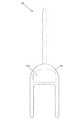
ここで図を参照すると、図1は、本出願の一態様によるプロジェクタホルダ100を示す。この図に示すように、プロジェクタホルダ100は、胴体103を有する本体102と、胴体103から外向きに延びる付属物104と、を含む。この図に示すように、ホルダ100は、5つの付属物104を含むことができるが、ホルダはより多い又は少ない付属物を含むことができる。例えば、ホルダ100は、他の実施形態では、1つ、2つ、3つ、又はそれ以上の付属物を含み得る。 With reference to the figures here, FIG. 1 shows the
付属物は、胴体103の1つ又は複数の面又は他の部分から外向きに延びることができる。例えば、図1に示すように、付属物は胴体103の頂部及び底部から外向きに延びることができる。他の実施形態では、付属物は、胴体の頂部のみ、底部のみ、又は他の面の1つ又は複数から(例えば、胴体の右面又は右面と左面)から外向きに延びてもよい。付属物はまた、胴体の縁部及び/又は角部から延びてもよい。 The appendages can extend outward from one or more surfaces or other parts of the
理解されるように、任意の適切な数の付属物が、胴体の所与の面又は他の部分から外向きに延びてもよい。例えば、ある実施形態では、図1に示されるように、1つの付属物104のみが胴体103のある面から(例えば、胴体の頂部から)延びることができる。他の実施形態では、2つ以上の付属物が胴体のある面から外向きに延びてもよい。例えば、図1において、4つの付属物が胴体の底部から外向きに延びている。さらに理解されるように、各胴部面又は他の部分から外向きに延びる付属物の数は同じでもよいが、外向きに延びる付属物の数は異なってもよい。 As will be appreciated, any suitable number of appendages may extend outward from a given surface or other part of the fuselage. For example, in one embodiment, as shown in FIG. 1, only one
付属物はまた、胴体の面又は他の部分の任意の適切な位置に配置されてもよい。例えば、図1に示すように、付属物は胴体の底部及び頂部の周囲に配置されてもよい。他の実施形態では、付属物は面のうちの1つの中央に配置されてもよい。 The accessories may also be placed at any suitable position on the surface of the fuselage or other parts. For example, as shown in FIG. 1, accessories may be placed around the bottom and top of the fuselage. In other embodiments, the appendages may be centered on one of the faces.
ある実施形態では、図1に示されるように、付属物104は胴体103と一体的に形成されてもよい。他の実施形態では、1つ又は複数の付属物は胴体に取り外し可能に取り付けられてもよい。理解されるように、全ての付属物が胴体に取り外し可能に取り付けられる必要はなく、胴体と一体的に形成される必要もない。例えば、胴体は、4つの一体的に形成された付属物と一体的に形成されてもよく、及び胴体に取り外し可能に取り付け可能な第5付属物。 In certain embodiments, the
ある実施形態において、付属物104のうちの1つ又は複数は、付属物を操作することによって(例えば、曲げる、ねじる、湾曲させる、真っ直ぐにすること等によって)付属物を変形させるのに十分に柔軟な材料から形成される。材料はまた、付属物が操作されない限り及び付属物が操作されるまで付属物が第1構成及び第2構成を維持するように、十分に形状保持性であってもよい。ある実施形態において、付属物は、図1に示されるように、柔軟な第2材料で被覆された柔軟なワイヤ111などの柔軟な金属から形成される。例えば、付属物は、シリコーン又はゴム材料で被覆される銅線から形成されてもよい。ある実施形態では、ワイヤ111は、胴体103から付属物104の端部まで延びることができる。ワイヤ111は、任意の適切な直径、例えば、直径約1mm〜3mm、又は直径約2mmを有することができる。 In certain embodiments, one or more of the
理解されるように、付属物は他の柔軟な第2材料で被覆された他の柔軟な金属(例えば、ワイヤ)から形成されてもよい。さらに理解されるように、付属物は被覆ワイヤから形成される必要がある。例えば、付属物は、形状保持プラスチックなどの他の柔軟な材料又は材料の組み合わせから形成されてもよい。 As will be appreciated, the appendages may be formed from other flexible metals (eg, wires) coated with another flexible second material. As further understood, the appendages need to be formed from coated wire. For example, the appendages may be formed from other flexible materials or material combinations such as shape-retaining plastics.
本体102の付属物104の全てが柔軟である必要はない。例えば、5つの付属物を有する実施形態では、4つの付属物のみが柔軟であり得る。他の実施形態では5つの付属物の全てが柔軟であり得る。さらに理解されるように、各付属物104の全長が柔軟である必要はない。例えば、ある実施形態では、付属物の半分、例えば、付属物の最も外側の部分のみが柔軟であり得るが、付属物全体が柔軟であってもよい。さらに、胴体部分は柔軟な材料から形成されてもよいが、柔軟ではない材料から形成されてもよい。 Not all of the
理解されるように、図1は、最初に操作によって付属物を変形させることなく、ホルダ100が表面110などの物体の外側に配置された例を示し得る。例えば、図1の付属物は、真っ直ぐな構成であってもよく、したがって、単に表面110上に配置されていてもよい。図1はまた、4つの全ての付属物104が表面上に配置される前に操作されて真っ直ぐな構成に変形されている例を示し得る。 As will be appreciated, FIG. 1 may show an example in which the
ある実施形態において、全ての付属物が表面110上にホルダを配置する前に操作及び変形されるわけではない。ある実施形態において、全ての付属物が同じ第2構成に操作及び変形されるわけではない。例えば、図3に示すように、後部付属物が(例えば、真っ直ぐな構成から)曲がった構成に操作され変形されている一方で前部付属物は真っ直ぐな構成にある。理解されるように、そのような例では、図3の前部付属物104aは、(例えば、曲がった構成から)真っ直ぐな構成に操作され変形されたかもしれないが、それらはまた、既に真っ直ぐな構成であった可能性があるので、最初に操作されなかった。いったんホルダが表面110上に置かれると、可視光112が表面110より上の所望の高さに投影され得るようにホルダ100の前面は持ち上げられる。 In certain embodiments, not all accessories are manipulated and deformed prior to placing the holder on the
さらに別の実施形態では、付属物はホルダを表面の外側に取り付けるように操作され変形され得る。すなわち、付属物は、ホルダ100を物体に対して保持するように第2構成に変形され得る。例えば、図4に示すように、付属物104は、付属物が椅子のアーム114の周りに巻き付けられ、ホルダの底部が椅子のアームの上面に対して保持されるように操作され変形されている。図4の付属物104の全てがホルダを椅子のアームに対して保持するために操作され変形されているが、他の実施形態では、付属物の全てが使用される必要はない。例えば、一実施形態では、ホルダを椅子のアームに保持するために2つの付属物のみを使用することができる。 In yet another embodiment, the appendages can be manipulated and deformed to attach the holder to the outside of the surface. That is, the appendages can be transformed into a second configuration to hold the
図4の付属物は、ホルダが(例えば、胴体の底部が物体の上面に隣接した状態で)直立位置にあるように操作され変形されているが、ホルダ100は他の位置で物体の外側に取り付けることもできる。例えば、ホルダは、プロジェクタの底部が物体の底部に隣接した状態で逆さまの位置に取り付けることができる。ホルダはまた、プロジェクタの底部が物体のある面に隣接した状態で胴体が垂直に位置付けられるように取り付けられてもよい。 The appendage of FIG. 4 is manipulated and deformed so that the holder is in an upright position (eg, with the bottom of the fuselage adjacent to the top surface of the object), while the
図1に戻ると、ある実施形態では、プロジェクタ106は、本体102の胴体103内など、ホルダ100の本体102内に配置することができる。ある実施形態では、示されるように、プロジェクタ104は本体102内に完全に配置される。他の実施形態では、プロジェクトは本体内に部分的にのみ配置されてもよい。例えば、プロジェクタ106の前面(例えば、レンズを有するプロジェクタの面)は、少なくとも部分的に本体102の外側に延在してもよい。 Returning to FIG. 1, in one embodiment, the
本明細書の目的のために、プロジェクタは、画像などの可視光を表面に投影する装置を含む。ある実施形態では、プロジェクタはレンズを介して可視光線を投影することができる。プロジェクタはレーザを介して画像を投影することもできる。理解されるように、プロジェクタは任意の適切なサイズを有してもよい。例えば、プロジェクタは、小型プロジェクタ又はフルサイズプロジェクタであり得る。プロジェクタは、表面に画像を投影するように構成されているスマートフォンなどのスマートデバイスを含むこともできる。プロジェクタは、二次元画像及び/又は三次元画像を表示することができる。プロジェクタはホログラフィック画像を表示することもできる。さらに理解されるように、画像はプレゼンテーションのスライドなどの静止フレームであってもよいし、動画であってもよい。 For the purposes of this specification, a projector includes a device that projects visible light, such as an image, onto a surface. In certain embodiments, the projector can project visible light through a lens. The projector can also project an image via a laser. As will be appreciated, the projector may have any suitable size. For example, the projector can be a small projector or a full size projector. Projectors can also include smart devices such as smartphones that are configured to project images onto a surface. The projector can display a two-dimensional image and / or a three-dimensional image. The projector can also display holographic images. As will be further understood, the image may be a static frame, such as a presentation slide, or it may be a moving image.
ある実施形態では、本体とプロジェクタが単一の一体型デバイスを形成するように、プロジェクタは本体と、例えば、胴体103及び付属物104の両方と一体に形成することができる。理解されるように、1つ又は複数の付属物が取り外し可能である実施形態では、プロジェクタは、胴体のみと一体的に形成されてもよい、又は胴体及び1つ又は複数の付属物と一体的に形成されてもよく、この際、1つ又は複数の付属物は同じく取り外し可能に取り付け可能である。 In certain embodiments, the projector can be formed integrally with the body and, for example, both the
他の実施形態では、プロジェクタ106は本体102に取り外し可能に取り付けられてもよい。図2に示すように、本体102は、プロジェクタ104を挿入することができる開口108を含むことができる。他の実施形態と同様に、プロジェクタ106は、開口108内に完全に配置されてもよく、又は開口内に部分的にのみ配置されてもよい。理解されるように、プロジェクタ108は、プロジェクタが使用されている間だけ開口108に挿入され、その後取り外されてもよい。プロジェクタ106はまた、使用のために開口108内に挿入され、保管のために開口108内に留まることができる。 In other embodiments, the
図1に戻ると、ホルダは、ユーザがプロジェクタを操作することを可能にするための1つ又は複数のボタンを含み得る。ある実施形態では、ホルダ上のボタンはプロジェクタ上のボタンである。例えば、ホルダは、ユーザがそれを通してプロジェクタ上のボタンにアクセスすることができる1つ又は複数の開口を含むことができる。プロジェクタとホルダとが一体的に形成されている1つのそのような例では、プロジェクタのボタンが配置されている場所を除いて、ホルダを形成するのに使用される材料(例えば、シリコーン又はゴム材料)でプロジェクタを覆うことができる。他の実施形態では、ホルダは、プロジェクタ上のボタンに対応し且つそれと相互作用するボタンを含み得る。例えば、ホルダは、ユーザがホルダボタンを押すとプロジェクタボタンを起動する(例えば、プロジェクタボタンを押す)シリコーン又はゴム製のボタンを含むことができる。 Returning to FIG. 1, the holder may include one or more buttons to allow the user to operate the projector. In some embodiments, the button on the holder is a button on the projector. For example, the holder can include one or more openings through which the user can access buttons on the projector. In one such example where the projector and holder are integrally formed, the material used to form the holder (eg, silicone or rubber material), except where the projector buttons are located. ) Can cover the projector. In other embodiments, the holder may include buttons that correspond to and interact with the buttons on the projector. For example, the holder can include a silicone or rubber button that activates the projector button (eg, pressing the projector button) when the user presses the holder button.
ある実施形態では、図1及び図5に示されるように、ホルダは、ユーザがプロジェクタをオン及びオフにすることを可能にするための電源ボタン116を含み得る。ある実施形態において、ホルダ100はまた、ユーザが投影されている画像の向きを回転させることを可能にする回転画像ボタン118を含み得る。例えば、ユーザがホルダを逆さまの位置で物体に取り付ける実施形態では、ユーザは、画像が所望の向き(例えば、右側を上にして)で表示されるまで回転画像ボタンを押すことができる。理解されるように、電源ボタン及び回転画像ボタンの両方がホルダの上面に示されているが、他の実施形態では、これらのボタンはホルダの別の適切な面又は部分に位置付けられてもよい。 In certain embodiments, as shown in FIGS. 1 and 5, the holder may include a
ある実施形態では、図6に示されるように、ホルダは、キーストン補正ボタン120を有し得る。そのような実施形態では、キーストン補正ボタンは、投影された画像をそれが長方形に見えるようにゆがめるために使用され得る。このような調整は、画像が投影されている表面の水平中心線に対してプロジェクタが垂直に配置されていないときに実行され得る。ある実施形態では、図6に示されるように、キーストン調整ボタン120は本体102の前面に配置されてもよい。例えば、キーストン調整ボタン120は、それを通して画像が表面124に表示される(図4参照)レンズ/レーザプロジェクタアイ122の隣に配置されてもよい。理解されるように、キーストン調整ボタン122は他の実施形態ではホルダの別の適切な面に配置されてもよい。 In certain embodiments, the holder may have a
次に図7を参照する。図7は、一実施形態によるプロジェクタホルダの背面を示す。この図に示されるように、プロジェクタホルダは、周辺機器をホルダ(及びプロジェクタ)に接続するための1つ又は複数のポートを含み得る。ボタンと同様に、ホルダポートもプロジェクタのポートとすることができるが、ホルダポートもプロジェクタのポートに対応して相互作用する別々のポートとすることができる。ある実施形態では、プロジェクタホルダは、プロジェクタをスマートデバイス(例えば、スマートフォン又は電子書籍リーダ)、コンピュータ及び/又はバッテリチャージャ(例えば、バッテリパック又は電源アダプタ)などの周辺機器に接続するためのUSBポート126及び/又はライトニングケーブルポート128を含むことができる。例えば、図4は、USBポート126に接続されたUSBケーブル125を介してスマートフォン130に接続されているプロジェクタホルダ100を示している。別の例として、図8は、プロジェクタを充電するためにUSBケーブル125及びUSBポート126を介してバッテリパック132に接続されたプロジェクタホルダ100を示す。理解されるように、USBポート及びライトニングケーブルポートだけが図7に示されているが、ホルダはプロジェクタを周辺機器に接続するのに適した他のポートを含むことができる。ホルダはまた、現在知られているか又は将来開発される通信プロトコルをサポートするための他のポートを含み得る。他の実施形態と同様に、ポートはプロジェクタホルダの背面に示されているが、ポートはプロジェクタの任意の適切な面に配置されてもよい。 Next, refer to FIG. FIG. 7 shows the back surface of the projector holder according to one embodiment. As shown in this figure, the projector holder may include one or more ports for connecting peripherals to the holder (and projector). Like the buttons, the holder port can be a projector port, but the holder port can also be a separate port that interacts with the projector port. In certain embodiments, the projector holder is a
プロジェクタホルダ100は、周辺機器をプロジェクタホルダ(及びプロジェクタ)に有線接続するための1つ又は複数のポートを備えて示されているが、周辺機器はホルダに無線接続することもできることは理解されよう。例えば、1つ又は複数の周辺機器をBluetooth(登録商標)又は他の適切な無線接続(Wi-Fi(登録商標)又はLi−Fi接続など)を介してホルダ(及びプロジェクタ)に接続することができる。 Although the
理解されるように、プロジェクタホルダ100は、プロジェクタを操作するための他の適切なボタン及び/又はポートを含み得る。例えば、ホルダは、ユーザがプロジェクタの明るさ及び/又は彩度を調整することを可能にするボタンを含み得る。ホルダはまた、状態(例えば、プロジェクタの又は環境の)を感知し、プロジェクタを動作させるためにデータをホルダ(及びプロジェクタ)に送り返す1つ又は複数のセンサを含み得る。例えば、プロジェクタホルダ100は、周囲光の状態を検出することができる周囲光センサ(図示せず)を含むことができる。そのような例では、プロジェクタは、感知された周囲光に応答して画像の明るさ及び/又は彩度を自動的に調整するように構成されてもよい。 As will be appreciated, the
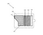
次に図9を参照する。図9は、プロジェクタの内部に収容され得る電気部品の例示的配置を示す。理解されるように、部品は、図9に示される順序どおりでなく、任意の順序で配置されてもよい。さらに理解されるように、プロジェクタは、他の実施形態において追加の又は代替の部品を含み得る。 Next, refer to FIG. FIG. 9 shows an exemplary arrangement of electrical components that can be housed inside a projector. As will be appreciated, the parts may be arranged in any order, not in the order shown in FIG. As will be further understood, the projector may include additional or alternative components in other embodiments.
ある実施形態では、図9に示すように、プロジェクタは、プロジェクタアイ/レンズ122を介して可視光を投影する投影ユニット134を含むことができる。プロジェクタはまた、モデム136、バッテリ138、及び1つ又は複数の周辺機器と接続するための1つ又は複数のポート140(例えば、USBポート)を含むことができる。ある実施形態において、モデム126は、送信のための情報(例えば、デジタル情報)を受信し変調するように構成される。 In certain embodiments, as shown in FIG. 9, the projector may include a
ある実施形態では、バッテリ138は、約1時間〜約4時間の間プロジェクタ105に電力を供給するように構成することができる。例えば、バッテリ138はプロジェクタを約1.5時間動作させることを可能にし得る。理解されるように、バッテリは、使い捨てであり得るか、又は再利用可能であり得る。バッテリが再利用可能である実施形態では、バッテリは、ホルダをバッテリパック(例えば、図8参照)又は電源アダプタに差し込むことによって充電されてもよく、電源アダプタはその後電源コンセントに差し込まれる。そのような実施形態では、ホルダ100は、USBケーブル又はライトニングケーブル及びそれぞれのポート126、128のうちの1つを介してバッテリチャージャに接続され得る。充電式バッテリはまた、バッテリパック132との接触又は近接により充電され得る。例えば、バッテリパックは(例えば、バッテリパック上の1つ又は複数の柔軟な付属物を介して)ホルダに取り付けることができる。 In certain embodiments, the
ある実施形態では、本体は、耐水性又は防水性材料、又はプロジェクタを保護するために耐水性又は防水性になるように処理された材料を含む。例えば、一実施形態では、本体は、シリコーン、ゴム、PVC、又はワックスから、或いはPVC、ポリウレタン、ゴム、シリコーンエラストマー、フルオロポリマー及び/又はワックスで処理(例えば、積層又はコーティング)された材料から形成されてもよい。他の防水性又は耐水性材料及び/又は処理を使用することもできる。 In certain embodiments, the body comprises a water resistant or waterproof material, or a material that has been treated to be water resistant or waterproof to protect the projector. For example, in one embodiment, the body is formed from silicone, rubber, PVC, or wax, or from a material treated (eg, laminated or coated) with PVC, polyurethane, rubber, silicone elastomer, fluoropolymer and / or wax. May be done. Other waterproof or water resistant materials and / or treatments can also be used.
ある実施形態において、ホルダは耐衝撃性であるように構成される。例えば、本体は、ホルダを落とした場合にプロジェクタを損傷から保護する材料から形成することができる。理解されるように、ある実施形態では、胴体のみが耐衝撃性材料から形成され、他の実施形態では、胴体及び付属物が耐衝撃性材料から形成される。耐衝撃性のあるいくつかの材料は、シリコーン、ゴム、EVA、発泡体、又は他の適切な材料を含む。 In certain embodiments, the holder is configured to be impact resistant. For example, the body can be made of a material that protects the projector from damage if the holder is dropped. As will be appreciated, in some embodiments only the fuselage is formed from impact resistant material and in other embodiments the fuselage and accessories are formed from impact resistant material. Some impact resistant materials include silicone, rubber, EVA, foam, or other suitable material.
ある実施形態では、胴体103及び付属物104は、同じ材料又は材料の組み合わせから形成される。例えば、付属物104と胴体103の両方を柔軟で耐衝撃性のある材料から形成することができる。例えば、付属物及び胴体は両方とも、シリコーン又はゴム材料から形成されてもよい。他の実施形態では、付属物は胴体とは異なる材料で形成される。例えば、付属物は柔軟な(そして場合によっては耐衝撃性のある)材料から形成され、一方胴体は耐衝撃性があるだけの材料から形成される。 In certain embodiments, the
ある実施形態では、ホルダはヒートシンクとして機能し、プロジェクタによって発生した熱を放散するように構成される。ある実施形態では、例えば、熱を放散させるために、1つ又は複数のワイヤ11(例えば、銅線)がプロジェクタの周囲及び/又は付属物の中に延在する。例えば、図1を参照のこと。図1では、ワイヤ111はプロジェクタの周囲及び各付属物の中に延びた状態で示されている。理解されるように、他の種類の金属(例えば、ワイヤ)、又は他の適切なヒートシンクを本体内に配置することができる。 In one embodiment, the holder acts as a heat sink and is configured to dissipate the heat generated by the projector. In certain embodiments, for example, one or more wires 11 (eg, copper wire) extend around the projector and / or in attachments to dissipate heat. See, for example, FIG. In FIG. 1, the
ある実施形態において、ホルダは動物の形状に形成され得る。そのような実施形態では、付属物は動物の肢又は他の末端に対応し得る。例えば、図1に示すように、本体102は、4本の肢(例えば、腕及び脚)及び尾を有するサルの形状であり得る。理解されるように、本体102は、キリン、ライオン、トラ、クマ、恐竜、トカゲ、魚、タコ、又は他の野生動物若しくは家畜などの他の動物の形状にも形成され得る。図1には示されていないが、本体はまた、動物の頭部(例えば、サルの頭部)に対応する付属物を含み得る。 In certain embodiments, the holder can be formed in the shape of an animal. In such embodiments, the appendages may correspond to the limbs or other ends of the animal. For example, as shown in FIG. 1, the
理解されるように、ホルダは任意の適切な色又は色の組み合わせであり得る。ある実施形態では、色又は色の組み合わせは本体の動物の形状に対応する。例えば、本体がサルの形状である実施形態では、本体は茶色であり得る。 As will be appreciated, the holder can be any suitable color or combination of colors. In certain embodiments, the color or combination of colors corresponds to the shape of the animal in the body. For example, in embodiments where the body is in the shape of a monkey, the body can be brown.
ある実施形態では、ホルダの外側はまた、ホルダの動物の形状に対応する1つ又は複数の装飾的特徴を含む。例えば、付属物は手及び足を有し得る。別の例では、動物がサルである場合、手の一方がバナナを握っていてもよい。 In certain embodiments, the outside of the holder also comprises one or more decorative features that correspond to the animal shape of the holder. For example, the appendages can have hands and feet. In another example, if the animal is a monkey, one of its hands may be holding a banana.
別の実施形態によれば、ホルダは表面上に画像を表示するために使用されるキットの一部である。そのような実施形態では、キットは、埋め込み型プロジェクタを有するホルダと、USB及び/又はライトニングケーブルと、を含み得る。理解されるように、ケーブルは任意の適切な長さであり得る。例えば、ケーブルの長さは3〜12フィートであり得る。例えば、ケーブルの長さは7フィートであり得る。ある実施形態において、キットはまた、図8に示されるバッテリパックなどのバッテリチャージャ又は電源アダプタを含み得る。 According to another embodiment, the holder is part of a kit used to display an image on the surface. In such an embodiment, the kit may include a holder with an embedded projector and a USB and / or lightning cable. As will be appreciated, the cable can be of any suitable length. For example, the length of the cable can be 3-12 feet. For example, the length of the cable can be 7 feet. In certain embodiments, the kit may also include a battery charger or power adapter, such as the battery pack shown in FIG.
別の実施形態によれば、図10に示すように、表面上に画像を表示するためにホルダを物体上に配置するか又は取り付ける方法200が開示されている。ある実施形態では、この方法は、1つ又は複数の付属物を操作及び変形すること250と、ホルダを物体上に配置すること252とを含む。理解されるように、ホルダは、付属物を最初に操作及び変形することなく物体上に配置されてもよい252。他の実施形態では、方法は、ホルダを物体に取り付けるために(例えば、物体の外側に対してホルダを保持するために)1つ又は複数の付属物を操作及び変形すること254を含む。そのような実施形態では、1つ又は複数の付属物を操作することは、付属物を第1構成から異なる第2構成に変形させるために付属物を真っ直ぐにする、曲げる、湾曲させる、ねじる、又は他の方法で移動することのうちの1つを含む。理解されるように、各付属物は異なる方法で操作され変形されてもよく、異なる第2構成を有してもよい。例えば、ある付属物が曲げられ得る一方で別の付属物は真っ直ぐにされる。 According to another embodiment, as shown in FIG. 10, a
いったんホルダが物体に取り付けられるか又は物体上に配置されると、方法は、有線又は無線接続を介して周辺機器(例えば、スマートフォン)を接続すること256、及び電源ボタンを押してプロジェクタをオンにすること258を含み得る。理解されるように、他の実施形態では、プロジェクタはリモートコントロールを介してオンにされてもよい。方法はまた、プロジェクタを調整するために1つ又は複数のホルダボタンを押すこと260を含み得る。例えば、方法は、画像を調整するためにキーストン調整ボタンを押すこと、及び/又は画像が直立した向きに置かれるように画像を回転するべく回転画像ボタンを押すことを含み得る。 Once the holder is attached to or placed on the object, the method is to connect a peripheral (eg, a smartphone) via a wired or
別の実施形態によれば、ホルダを製造する方法300が開示されている。ある実施形態では、図11に示すように、この方法は、1つ又は複数の柔軟な付属物362と、プロジェクタを挿入することができる開口と、を有する本体を形成することを含む。理解されるように、プロジェクタは、製造中及び/又はその後ユーザ364によって開口に挿入することができる364。このような実施形態では、本体はシリコーン又はゴム材料を型に流し込むことによって形成することができる。他の実施形態では、図12に示すように(ここではプロジェクタはホルダと一体的に形成されている)、方法は、1つ又は複数の柔軟な付属物と、本体内に少なくとも部分的に配置されたプロジェクタと、を有する本体を形成すること366を含む。ある実施形態では、この方法は、プロジェクタを型の中に配置することと、シリコーン又はゴム材料を型内及びプロジェクタの周囲に流し込むこととを含む。他の実施形態では、方法は、1つ又は複数の柔軟な付属物を有する本体が形成されるまで、浸漬すること又は他の方法でプロジェクタの外側にシリコーン又はゴム材料を(例えば、層ごとに堆積することによって)塗布することを含み得る。 According to another embodiment, a
ある実施形態では、方法は、シリコーン又はゴム材料を塗布する前に、プロジェクタの周りに、及びある実施形態ではプロジェクタから1つ又は複数の付属物まで外向きに1つ又は複数の銅線を巻き付けることを含み得る。理解されるように、ある実施形態では、銅線は1つ又は複数の付属物の内部構造を画定するために使用され得る一方、プロジェクタは、胴体の内部を画定するために使用され得る。 In some embodiments, the method wraps one or more copper wires around the projector and, in some embodiments, outwards from the projector to one or more accessories before applying the silicone or rubber material. Can include that. As will be appreciated, in certain embodiments, copper wire can be used to define the internal structure of one or more appendages, while projectors can be used to define the interior of the fuselage.
本教示を様々な実施形態及び実施例と併せて記載してきたが、本教示がそのような実施形態又は実施例に限定されることは意図しない。それどころか、本教示は、当業者には理解されるように、様々な代替形態、修正形態、及び均等物を包含する。したがって、前述の記載及び図面は例にすぎない。 Although this teaching has been described in conjunction with various embodiments and examples, it is not intended that this teaching be limited to such embodiments or examples. On the contrary, the teachings include various alternatives, modifications, and equivalents, as will be appreciated by those skilled in the art. Therefore, the above description and drawings are merely examples.
本発明の様々な態様は、単独で、組み合わせて、又は前述の実施形態で具体的に考察されていない様々な構成で使用することができ、したがってその使用において前述の又は図面に示される構成要素の詳細及び構成に限定されない。例えば、一実施形態に記載の態様は、他の実施形態に記載の態様と任意の方法で組み合わせることができる。 Various aspects of the invention can be used alone, in combination, or in various configurations not specifically discussed in the embodiments described above, and thus the components described above or in the drawings in their use. The details and composition of the above are not limited. For example, the embodiments described in one embodiment can be combined with the embodiments described in other embodiments in any way.
また、本発明は方法として具現化することができ、その例が提供された。方法の一部として実行される行為は、任意の適切な方法で順序付けられてもよい。したがって、例示的な実施形態において連続的な行為として示されているとしても、いくつかの行為を同時に実行することを含み得る、示されているのとは異なる順序で行為が実行される実施形態が構成されてもよい。 Further, the present invention can be embodied as a method, and an example thereof has been provided. The actions performed as part of the method may be ordered in any suitable way. Thus, embodiments in which actions are performed in a different order than shown, which may include performing several actions simultaneously, even though they are shown as continuous actions in an exemplary embodiment. May be configured.
クレーム要素を部分的に変更するクレーム中の「第1」、「第2」、「第3」等などの序数用語の使用は、それ自体では、あるクレーム要素の別のクレーム要素を上回る優先度、優先順位、若しくは順序、又は方法の行為が実行される時間的順番を含意せず、クレーム要素を区別するために、ある名前を持つ1つのクレーム要素を、(序数用語の使用を除いて)同じ名前を持つ別の要素と区別するための単なる標示として使用される。 Partially Modifying a Claim Element The use of ordinal terms such as "first," "second," "third," etc. in a claim has itself a priority over another claim element of one claim element. , Priority, or order, or one claim element with a name (except for the use of ordinal terms) to distinguish claim elements without implying the temporal order in which the act of the method is performed. It is used simply as a sign to distinguish it from another element with the same name.
また、本明細書で使用されている表現及び用語は説明を目的としており、限定と見なされるべきではない。本明細書における「含む(including)」、「含む(comprising)」、又は「有する(having)」、「含有する(containing)」、「伴う(involving)」、及びそれらの変形の使用は、その後に列挙される項目及びその均等物、並びに追加の項目を包含することを意味する。 Also, the expressions and terms used herein are for illustration purposes only and should not be considered limiting. The use of "including", "comprising", or "having", "containing", "involving", and variations thereof herein thereafter. Means include the items listed in, and their equivalents, as well as additional items.
Claims (23)
Translated fromJapanese前記本体内に少なくとも部分的に配置されたプロジェクタであって、可視光を表面に投影するために使用可能であるプロジェクタと、を含む装置であって、
前記本体は、物体の外側に前記装置を取り付けるか又は前記装置を配置するために第1構成から第2構成に操作及び変形されるように構成された1つ又は複数の柔軟な付属物を含む、装置。With the main body
A device comprising a projector that is at least partially disposed within the body and that can be used to project visible light onto a surface.
The body comprises one or more flexible appendages configured to mount the device on the outside of an object or to be manipulated and transformed from a first configuration to a second configuration for arranging the device. ,apparatus.
1つ又は複数の柔軟な付属物を有する本体と、前記本体内に少なくとも部分的に配置されたプロジェクタと、を有する装置を形成することを含み、前記1つ又は複数の柔軟な付属物は、物体の外側に前記装置を配置するか又は前記装置を取り付けるために第1構成から第2構成に操作及び変形されるように構成される、方法。A method of manufacturing equipment
The one or more flexible accessories comprises forming a device having a body having one or more flexible accessories and a projector at least partially disposed within the body. A method of arranging the device outside an object or being configured to be manipulated and transformed from a first configuration to a second configuration for mounting the device.
Priority Applications (1)
| Application Number | Priority Date | Filing Date | Title |
|---|---|---|---|
| JP2021158521AJP7150119B2 (en) | 2016-06-17 | 2021-09-28 | projector holder |
Applications Claiming Priority (5)
| Application Number | Priority Date | Filing Date | Title |
|---|---|---|---|
| US201662351527P | 2016-06-17 | 2016-06-17 | |
| US62/351,527 | 2016-06-17 | ||
| US15/376,518US9891509B2 (en) | 2016-06-17 | 2016-12-12 | Projector holder |
| US15/376,518 | 2016-12-12 | ||
| JP2018565340AJP6770592B2 (en) | 2016-06-17 | 2017-06-15 | Projector holder |
Related Parent Applications (1)
| Application Number | Title | Priority Date | Filing Date |
|---|---|---|---|
| JP2018565340ADivisionJP6770592B2 (en) | 2016-06-17 | 2017-06-15 | Projector holder |
Related Child Applications (1)
| Application Number | Title | Priority Date | Filing Date |
|---|---|---|---|
| JP2021158521ADivisionJP7150119B2 (en) | 2016-06-17 | 2021-09-28 | projector holder |
Publications (2)
| Publication Number | Publication Date |
|---|---|
| JP2020201519Atrue JP2020201519A (en) | 2020-12-17 |
| JP6967640B2 JP6967640B2 (en) | 2021-11-17 |
Family
ID=60660819
Family Applications (5)
| Application Number | Title | Priority Date | Filing Date |
|---|---|---|---|
| JP2018565340AActiveJP6770592B2 (en) | 2016-06-17 | 2017-06-15 | Projector holder |
| JP2020160316AActiveJP6967640B2 (en) | 2016-06-17 | 2020-09-25 | Projector holder |
| JP2021158521AActiveJP7150119B2 (en) | 2016-06-17 | 2021-09-28 | projector holder |
| JP2022153881AActiveJP7493561B2 (en) | 2016-06-17 | 2022-09-27 | Projector Holder |
| JP2024026580APendingJP2024055920A (en) | 2016-06-17 | 2024-02-26 | Projector Holder |
Family Applications Before (1)
| Application Number | Title | Priority Date | Filing Date |
|---|---|---|---|
| JP2018565340AActiveJP6770592B2 (en) | 2016-06-17 | 2017-06-15 | Projector holder |
Family Applications After (3)
| Application Number | Title | Priority Date | Filing Date |
|---|---|---|---|
| JP2021158521AActiveJP7150119B2 (en) | 2016-06-17 | 2021-09-28 | projector holder |
| JP2022153881AActiveJP7493561B2 (en) | 2016-06-17 | 2022-09-27 | Projector Holder |
| JP2024026580APendingJP2024055920A (en) | 2016-06-17 | 2024-02-26 | Projector Holder |
Country Status (5)
| Country | Link |
|---|---|
| US (7) | US9891509B2 (en) |
| JP (5) | JP6770592B2 (en) |
| KR (1) | KR102231018B1 (en) |
| CN (2) | CN109643054B (en) |
| WO (1) | WO2017218732A1 (en) |
Families Citing this family (7)
| Publication number | Priority date | Publication date | Assignee | Title |
|---|---|---|---|---|
| US9891509B2 (en)* | 2016-06-17 | 2018-02-13 | Mimono LLC | Projector holder |
| DE102017121782A1 (en)* | 2016-09-21 | 2018-03-22 | Tymphany Hk Limited | Audio and video protection system |
| US10418005B2 (en)* | 2016-10-21 | 2019-09-17 | Robert Shepard | Multimedia display apparatus and method of use thereof |
| USD803931S1 (en)* | 2016-12-12 | 2017-11-28 | Mimono LLC | Projector holder |
| USD893579S1 (en)* | 2017-07-17 | 2020-08-18 | Shared Space Studios LLC | At-home portal device |
| US20190096297A1 (en)* | 2017-09-28 | 2019-03-28 | Benjamin Cary | Vehicle mounted image projection system |
| KR20240085017A (en)* | 2022-12-07 | 2024-06-14 | 현대자동차주식회사 | Beam projector apparaus for vehicle |
Citations (11)
| Publication number | Priority date | Publication date | Assignee | Title |
|---|---|---|---|---|
| JP2006208901A (en)* | 2005-01-31 | 2006-08-10 | Seiko Epson Corp | projector |
| US20090121104A1 (en)* | 2007-11-14 | 2009-05-14 | Prodisc Technology Inc. | Projector, fastening assembly thereof and fastening method thereof |
| JP2009522516A (en)* | 2006-01-03 | 2009-06-11 | ジョビー インコーポレーテッド | Mounting device with grip function using ball and socket joint |
| US20100240277A1 (en)* | 2007-10-15 | 2010-09-23 | Btendo Ltd. | Toy assembly |
| US20110042536A1 (en)* | 2009-08-19 | 2011-02-24 | Thule Organization Solutions, Inc. | Selectively Positionable Device for Securing an Instrument |
| US20110297718A1 (en)* | 2010-01-25 | 2011-12-08 | Thierry Klein | Inflatable device for adjusting the projection angle and/or height of a video projector |
| JP2012078487A (en)* | 2010-09-30 | 2012-04-19 | Sanyo Electric Co Ltd | Projection type video display device |
| US20130280985A1 (en)* | 2012-04-24 | 2013-10-24 | Peter Klein | Bedtime toy |
| JP2014038129A (en)* | 2012-08-10 | 2014-02-27 | Canon Inc | Image projection device, and control method and control program therefor |
| JP2014115558A (en)* | 2012-12-12 | 2014-06-26 | Seiko Epson Corp | Projector |
| US20150147932A1 (en)* | 2013-10-28 | 2015-05-28 | Francisco Vizcarra | Toy Projector |
Family Cites Families (69)
| Publication number | Priority date | Publication date | Assignee | Title |
|---|---|---|---|---|
| USD275683S (en) | 1982-02-10 | 1984-09-25 | Eastman Kodak Company | Projector light source or similar article |
| US5545072A (en)* | 1994-07-27 | 1996-08-13 | Toy Biz, Inc. | Image projective toy |
| TW512214B (en)* | 2000-01-07 | 2002-12-01 | Koninkl Philips Electronics Nv | Luminaire |
| JP3219750B2 (en) | 2000-02-15 | 2001-10-15 | 株式会社エレマック | Storage equipment for video equipment |
| US6595646B2 (en)* | 2001-03-19 | 2003-07-22 | 3M Innovative Properties Company | Low profile overhead projector having a foldable post |
| JP2002311503A (en)* | 2001-04-19 | 2002-10-23 | Mitsubishi Electric Corp | Image quality correction system |
| US20060170669A1 (en)* | 2002-08-12 | 2006-08-03 | Walker Jay S | Digital picture frame and method for editing |
| JP2004167627A (en) | 2002-11-20 | 2004-06-17 | Plus Vision Corp | Robot having image projecting function, and information exchange system using the same |
| KR100642598B1 (en) | 2003-09-25 | 2006-11-10 | 박성태 | Projector case with air cleaner |
| US7334898B2 (en)* | 2003-10-10 | 2008-02-26 | Seiko Epson Corporation | Projector |
| US7064956B2 (en)* | 2003-12-01 | 2006-06-20 | Hewlett-Packard Development Company, L.P. | Cooling system for a display projector |
| JP2005313291A (en)* | 2004-04-30 | 2005-11-10 | Mitsubishi Heavy Ind Ltd | Image display method linked with robot action, and device thereof |
| JP2006047893A (en) | 2004-08-09 | 2006-02-16 | Seiko Epson Corp | LCD projector storage device |
| US7329005B2 (en)* | 2004-08-31 | 2008-02-12 | Hitachi Global Storage Technologies Netherlands B.V. | Method and system for a beam projector having an audio capability device |
| BRPI0608841A2 (en)* | 2005-03-10 | 2010-02-02 | Nissha Printing | method for producing housing for electronic apparatus |
| JP2006308885A (en)* | 2005-04-28 | 2006-11-09 | Olympus Corp | Projector |
| JP4552784B2 (en)* | 2005-07-07 | 2010-09-29 | コニカミノルタオプト株式会社 | Imaging element fixing structure, lens unit, and imaging apparatus |
| US8251536B2 (en) | 2006-01-03 | 2012-08-28 | Daymen Us, Inc. | Flashlight with mounting apparatus |
| JP2008020646A (en)* | 2006-07-12 | 2008-01-31 | Sony Corp | Imaging device |
| JP4265632B2 (en)* | 2006-08-31 | 2009-05-20 | セイコーエプソン株式会社 | projector |
| JP2008076806A (en) | 2006-09-22 | 2008-04-03 | Seiko Epson Corp | Projector and carrying case |
| CN200972043Y (en)* | 2006-11-23 | 2007-11-07 | 赵勇 | Self-position miniature tripod |
| JP2008155351A (en) | 2006-12-26 | 2008-07-10 | Olympus Corp | Robot |
| US20080232097A1 (en)* | 2007-03-23 | 2008-09-25 | Samir Gandhi | Flashlight having independently adjustable legs |
| US20090141196A1 (en) | 2007-12-03 | 2009-06-04 | Basner Charles M | Photo microprojector |
| CN101598887A (en)* | 2008-06-06 | 2009-12-09 | 宏碁股份有限公司 | projection device |
| TWM347014U (en)* | 2008-07-04 | 2008-12-11 | yi-fang Zhuang | Handheld electronic device with micro projection module |
| JP2010060600A (en)* | 2008-09-01 | 2010-03-18 | Seiko Epson Corp | Projector installation device |
| TWI499418B (en)* | 2009-05-21 | 2015-09-11 | Nerviano Medical Sciences Srl | Isoquinolin-1(2h)-one derivatives |
| CN201487493U (en)* | 2009-08-26 | 2010-05-26 | 中山日高精密工业有限公司 | a tripod |
| JP3158220U (en)* | 2009-09-05 | 2010-03-25 | 有限会社ラビット | Small projection toys |
| JP5688574B2 (en) | 2009-11-04 | 2015-03-25 | 株式会社国際電気通信基礎技術研究所 | Robot with tactile display |
| CN202109160U (en)* | 2011-01-29 | 2012-01-11 | 王志强 | Electric appliance supporting and fixing base |
| CN102207671B (en) | 2011-05-30 | 2012-11-21 | 鸿富锦精密工业(深圳)有限公司 | Projector Mounts and Projector Systems |
| CN202221512U (en)* | 2011-09-09 | 2012-05-16 | 李卫泽 | Projector equipment protective cover |
| JP2013083735A (en) | 2011-10-07 | 2013-05-09 | Panasonic Corp | Image display device |
| USD694761S1 (en) | 2011-12-14 | 2013-12-03 | Brian Michael Zoll | Multi-purpose positional support for accessories such as portable digital devices |
| CN103246138A (en)* | 2012-02-09 | 2013-08-14 | 鸿富锦精密工业(深圳)有限公司 | Multifunctional projector |
| CN202502339U (en)* | 2012-02-22 | 2012-10-24 | 金老虎 | Multifunctional Octopus Tripod |
| CN202453639U (en)* | 2012-03-15 | 2012-09-26 | 安徽理工大学 | Fixing device for a projector |
| CN202856861U (en) | 2012-09-24 | 2013-04-03 | 东莞市台德实业有限公司 | A multi-angle bending camera |
| US9244337B2 (en)* | 2012-11-08 | 2016-01-26 | Orion Innovations, Llc | Sports camera mounting apparatus |
| CN103869588B (en)* | 2012-12-11 | 2017-01-18 | 信泰光学(深圳)有限公司 | Micro projector system and additional enhanced heat radiation method |
| JP6255674B2 (en) | 2013-02-27 | 2018-01-10 | 株式会社リコー | Storage case |
| US20140267031A1 (en)* | 2013-03-12 | 2014-09-18 | Kenneth J. Huebner | Spatially aware pointer for mobile appliances |
| JP6302165B2 (en) | 2013-03-27 | 2018-03-28 | セコム株式会社 | Image projection system |
| US20140326839A1 (en) | 2013-05-01 | 2014-11-06 | Keizus, Inc. | Support for positioning an article in a free standing manner |
| KR101599340B1 (en) | 2013-07-23 | 2016-03-03 | (주)로보티즈 | Projecting unit having function of game platform |
| JP6236980B2 (en) | 2013-08-15 | 2017-11-29 | カシオ計算機株式会社 | Projector case |
| CN203720519U (en)* | 2013-12-11 | 2014-07-16 | 北京鸿合盛视数字媒体技术有限公司 | Projector support wall-hanging piece |
| CN104763865A (en)* | 2014-01-02 | 2015-07-08 | 天津华网畅达科技有限公司 | Magnetic suspension support of acupuncture point shooting and projecting device |
| US9341306B2 (en)* | 2014-02-10 | 2016-05-17 | Spydermount Llc | Accessory mounting apparatus |
| WO2015127529A1 (en)* | 2014-02-27 | 2015-09-03 | Kashlakov Roman | Systems and methods for electronic devices |
| CN204331269U (en)* | 2014-03-05 | 2015-05-13 | 上海本星电子科技有限公司 | Be convenient to the light curtain generator be fixed on projection screen |
| CN203950109U (en)* | 2014-03-14 | 2014-11-19 | 广州虹天航空科技有限公司 | Capture apparatus stabilizator |
| JP2015184587A (en) | 2014-03-25 | 2015-10-22 | セイコーエプソン株式会社 | Projector, storage unit, and projection apparatus |
| KR101585923B1 (en) | 2014-08-14 | 2016-01-18 | 고영봉 | Protctive case for mobile phone |
| KR20160028034A (en)* | 2014-09-02 | 2016-03-11 | 씨제이씨지브이 주식회사 | Movable table for projector |
| US20160109057A1 (en)* | 2014-10-20 | 2016-04-21 | Creative Digital Systems Integration, Inc. | Angular positioning apparatus |
| CN204256345U (en) | 2014-10-24 | 2015-04-08 | 深圳市强普光电有限公司 | A kind of children projector |
| CN204477633U (en)* | 2015-03-09 | 2015-07-15 | 浙江海洋学院 | Integral type projector mount |
| CN104698728A (en)* | 2015-03-27 | 2015-06-10 | 百度在线网络技术(北京)有限公司 | Micro-projector as well as operating method and operating device of micro-projector |
| CN204942945U (en)* | 2015-08-25 | 2016-01-06 | 闫晗 | A kind of collapsible multimedia overhead projector machine support with heat sinking function |
| CN105652576B (en)* | 2016-03-09 | 2017-09-26 | 宁波萨瑞通讯有限公司 | The adjusting device and method of adjust automatically projector position |
| US9891509B2 (en) | 2016-06-17 | 2018-02-13 | Mimono LLC | Projector holder |
| USD803931S1 (en) | 2016-12-12 | 2017-11-28 | Mimono LLC | Projector holder |
| USD803929S1 (en) | 2016-12-12 | 2017-11-28 | Mimono LLC | Projector holder |
| USD803930S1 (en) | 2016-12-12 | 2017-11-28 | Mimono LLC | Projector holder |
| JP7425646B2 (en)* | 2020-03-26 | 2024-01-31 | 日清紡マイクロデバイス株式会社 | limiter circuit |
- 2016
- 2016-12-12USUS15/376,518patent/US9891509B2/enactiveActive
- 2017
- 2017-06-15KRKR1020197001442Apatent/KR102231018B1/enactiveActive
- 2017-06-15JPJP2018565340Apatent/JP6770592B2/enactiveActive
- 2017-06-15CNCN201780050942.2Apatent/CN109643054B/enactiveActive
- 2017-06-15CNCN202110539341.6Apatent/CN113418116B/enactiveActive
- 2017-06-15WOPCT/US2017/037605patent/WO2017218732A1/ennot_activeCeased
- 2017-10-19USUS15/788,557patent/US20180039167A1/ennot_activeAbandoned
- 2018
- 2018-08-16USUS15/998,759patent/US10379429B2/enactiveActive
- 2019
- 2019-07-02USUS16/460,794patent/US11126070B2/enactiveActive
- 2020
- 2020-09-25JPJP2020160316Apatent/JP6967640B2/enactiveActive
- 2021
- 2021-08-02USUS17/391,441patent/US11740542B2/enactiveActive
- 2021-09-28JPJP2021158521Apatent/JP7150119B2/enactiveActive
- 2022
- 2022-09-27JPJP2022153881Apatent/JP7493561B2/enactiveActive
- 2023
- 2023-07-11USUS18/350,063patent/US12242176B2/enactiveActive
- 2024
- 2024-02-26JPJP2024026580Apatent/JP2024055920A/enactivePending
- 2025
- 2025-01-15USUS19/021,986patent/US20250155786A1/enactivePending
Patent Citations (11)
| Publication number | Priority date | Publication date | Assignee | Title |
|---|---|---|---|---|
| JP2006208901A (en)* | 2005-01-31 | 2006-08-10 | Seiko Epson Corp | projector |
| JP2009522516A (en)* | 2006-01-03 | 2009-06-11 | ジョビー インコーポレーテッド | Mounting device with grip function using ball and socket joint |
| US20100240277A1 (en)* | 2007-10-15 | 2010-09-23 | Btendo Ltd. | Toy assembly |
| US20090121104A1 (en)* | 2007-11-14 | 2009-05-14 | Prodisc Technology Inc. | Projector, fastening assembly thereof and fastening method thereof |
| US20110042536A1 (en)* | 2009-08-19 | 2011-02-24 | Thule Organization Solutions, Inc. | Selectively Positionable Device for Securing an Instrument |
| US20110297718A1 (en)* | 2010-01-25 | 2011-12-08 | Thierry Klein | Inflatable device for adjusting the projection angle and/or height of a video projector |
| JP2012078487A (en)* | 2010-09-30 | 2012-04-19 | Sanyo Electric Co Ltd | Projection type video display device |
| US20130280985A1 (en)* | 2012-04-24 | 2013-10-24 | Peter Klein | Bedtime toy |
| JP2014038129A (en)* | 2012-08-10 | 2014-02-27 | Canon Inc | Image projection device, and control method and control program therefor |
| JP2014115558A (en)* | 2012-12-12 | 2014-06-26 | Seiko Epson Corp | Projector |
| US20150147932A1 (en)* | 2013-10-28 | 2015-05-28 | Francisco Vizcarra | Toy Projector |
Also Published As
| Publication number | Publication date |
|---|---|
| US20200004116A1 (en) | 2020-01-02 |
| CN109643054B (en) | 2021-06-08 |
| CN113418116B (en) | 2023-07-04 |
| JP2022008604A (en) | 2022-01-13 |
| JP2022186706A (en) | 2022-12-15 |
| CN109643054A (en) | 2019-04-16 |
| US20240069419A1 (en) | 2024-02-29 |
| US12242176B2 (en) | 2025-03-04 |
| JP6967640B2 (en) | 2021-11-17 |
| KR20190020048A (en) | 2019-02-27 |
| US11740542B2 (en) | 2023-08-29 |
| JP7493561B2 (en) | 2024-05-31 |
| JP2019521375A (en) | 2019-07-25 |
| US20220019135A1 (en) | 2022-01-20 |
| US20180039167A1 (en) | 2018-02-08 |
| US11126070B2 (en) | 2021-09-21 |
| US9891509B2 (en) | 2018-02-13 |
| US20180364550A1 (en) | 2018-12-20 |
| US20170363938A1 (en) | 2017-12-21 |
| JP7150119B2 (en) | 2022-10-07 |
| CN113418116A (en) | 2021-09-21 |
| US10379429B2 (en) | 2019-08-13 |
| JP2024055920A (en) | 2024-04-19 |
| JP6770592B2 (en) | 2020-10-14 |
| WO2017218732A1 (en) | 2017-12-21 |
| US20250155786A1 (en) | 2025-05-15 |
| KR102231018B1 (en) | 2021-03-24 |
Similar Documents
| Publication | Publication Date | Title |
|---|---|---|
| JP6967640B2 (en) | Projector holder | |
| US11405066B2 (en) | Apparatus and method for supporting an article | |
| US10260735B2 (en) | Quickly charger has USB charging-ports for lighted cosmetic mirror device or lighting device | |
| US9169959B2 (en) | Universal tablet and smartphone holder | |
| HK40060912A (en) | Projector holder | |
| HK40060912B (en) | Projector holder | |
| HK40007257A (en) | Projector holder | |
| HK40007257B (en) | Projector holder | |
| KR101429394B1 (en) | Supporter for mobile device | |
| CN206725925U (en) | Image servicing unit | |
| CN213690389U (en) | Protective shell device for acquiring ultraviolet image and ultraviolet image display system | |
| WO2023030465A1 (en) | Charging device and charging system | |
| CN206257420U (en) | A kind of automatic panorama camera photography platform | |
| CN205017050U (en) | Portable power supply device | |
| JP2002057924A (en) | Photo frame equipment | |
| TW201422393A (en) | Tool box structure |
Legal Events
| Date | Code | Title | Description |
|---|---|---|---|
| A521 | Request for written amendment filed | Free format text:JAPANESE INTERMEDIATE CODE: A523 Effective date:20201015 | |
| A621 | Written request for application examination | Free format text:JAPANESE INTERMEDIATE CODE: A621 Effective date:20201015 | |
| A131 | Notification of reasons for refusal | Free format text:JAPANESE INTERMEDIATE CODE: A131 Effective date:20210630 | |
| A521 | Request for written amendment filed | Free format text:JAPANESE INTERMEDIATE CODE: A523 Effective date:20210928 | |
| TRDD | Decision of grant or rejection written | ||
| A01 | Written decision to grant a patent or to grant a registration (utility model) | Free format text:JAPANESE INTERMEDIATE CODE: A01 Effective date:20211011 | |
| A61 | First payment of annual fees (during grant procedure) | Free format text:JAPANESE INTERMEDIATE CODE: A61 Effective date:20211025 | |
| R150 | Certificate of patent or registration of utility model | Ref document number:6967640 Country of ref document:JP Free format text:JAPANESE INTERMEDIATE CODE: R150 | |
| R250 | Receipt of annual fees | Free format text:JAPANESE INTERMEDIATE CODE: R250 |