JP2020198994A - Walking training system and control program of walking training system - Google Patents
Walking training system and control program of walking training systemDownload PDFInfo
- Publication number
- JP2020198994A JP2020198994AJP2019106942AJP2019106942AJP2020198994AJP 2020198994 AJP2020198994 AJP 2020198994AJP 2019106942 AJP2019106942 AJP 2019106942AJP 2019106942 AJP2019106942 AJP 2019106942AJP 2020198994 AJP2020198994 AJP 2020198994A
- Authority
- JP
- Japan
- Prior art keywords
- trainee
- walking
- unit
- display
- control unit
- Prior art date
- Legal status (The legal status is an assumption and is not a legal conclusion. Google has not performed a legal analysis and makes no representation as to the accuracy of the status listed.)
- Granted
Links
Images


Classifications
- A—HUMAN NECESSITIES
- A61—MEDICAL OR VETERINARY SCIENCE; HYGIENE
- A61H—PHYSICAL THERAPY APPARATUS, e.g. DEVICES FOR LOCATING OR STIMULATING REFLEX POINTS IN THE BODY; ARTIFICIAL RESPIRATION; MASSAGE; BATHING DEVICES FOR SPECIAL THERAPEUTIC OR HYGIENIC PURPOSES OR SPECIFIC PARTS OF THE BODY
- A61H1/00—Apparatus for passive exercising; Vibrating apparatus; Chiropractic devices, e.g. body impacting devices, external devices for briefly extending or aligning unbroken bones
- G—PHYSICS
- G16—INFORMATION AND COMMUNICATION TECHNOLOGY [ICT] SPECIALLY ADAPTED FOR SPECIFIC APPLICATION FIELDS
- G16H—HEALTHCARE INFORMATICS, i.e. INFORMATION AND COMMUNICATION TECHNOLOGY [ICT] SPECIALLY ADAPTED FOR THE HANDLING OR PROCESSING OF MEDICAL OR HEALTHCARE DATA
- G16H20/00—ICT specially adapted for therapies or health-improving plans, e.g. for handling prescriptions, for steering therapy or for monitoring patient compliance
- G16H20/30—ICT specially adapted for therapies or health-improving plans, e.g. for handling prescriptions, for steering therapy or for monitoring patient compliance relating to physical therapies or activities, e.g. physiotherapy, acupressure or exercising
- A—HUMAN NECESSITIES
- A61—MEDICAL OR VETERINARY SCIENCE; HYGIENE
- A61B—DIAGNOSIS; SURGERY; IDENTIFICATION
- A61B5/00—Measuring for diagnostic purposes; Identification of persons
- A61B5/103—Measuring devices for testing the shape, pattern, colour, size or movement of the body or parts thereof, for diagnostic purposes
- A61B5/11—Measuring movement of the entire body or parts thereof, e.g. head or hand tremor or mobility of a limb
- A61B5/112—Gait analysis
- A—HUMAN NECESSITIES
- A61—MEDICAL OR VETERINARY SCIENCE; HYGIENE
- A61B—DIAGNOSIS; SURGERY; IDENTIFICATION
- A61B5/00—Measuring for diagnostic purposes; Identification of persons
- A61B5/103—Measuring devices for testing the shape, pattern, colour, size or movement of the body or parts thereof, for diagnostic purposes
- A61B5/11—Measuring movement of the entire body or parts thereof, e.g. head or hand tremor or mobility of a limb
- A61B5/1126—Measuring movement of the entire body or parts thereof, e.g. head or hand tremor or mobility of a limb using a particular sensing technique
- A61B5/1128—Measuring movement of the entire body or parts thereof, e.g. head or hand tremor or mobility of a limb using a particular sensing technique using image analysis
- A—HUMAN NECESSITIES
- A61—MEDICAL OR VETERINARY SCIENCE; HYGIENE
- A61B—DIAGNOSIS; SURGERY; IDENTIFICATION
- A61B5/00—Measuring for diagnostic purposes; Identification of persons
- A61B5/74—Details of notification to user or communication with user or patient; User input means
- A61B5/742—Details of notification to user or communication with user or patient; User input means using visual displays
- A—HUMAN NECESSITIES
- A61—MEDICAL OR VETERINARY SCIENCE; HYGIENE
- A61H—PHYSICAL THERAPY APPARATUS, e.g. DEVICES FOR LOCATING OR STIMULATING REFLEX POINTS IN THE BODY; ARTIFICIAL RESPIRATION; MASSAGE; BATHING DEVICES FOR SPECIAL THERAPEUTIC OR HYGIENIC PURPOSES OR SPECIFIC PARTS OF THE BODY
- A61H1/00—Apparatus for passive exercising; Vibrating apparatus; Chiropractic devices, e.g. body impacting devices, external devices for briefly extending or aligning unbroken bones
- A61H1/02—Stretching or bending or torsioning apparatus for exercising
- A61H1/0237—Stretching or bending or torsioning apparatus for exercising for the lower limbs
- A61H1/024—Knee
- A—HUMAN NECESSITIES
- A61—MEDICAL OR VETERINARY SCIENCE; HYGIENE
- A61H—PHYSICAL THERAPY APPARATUS, e.g. DEVICES FOR LOCATING OR STIMULATING REFLEX POINTS IN THE BODY; ARTIFICIAL RESPIRATION; MASSAGE; BATHING DEVICES FOR SPECIAL THERAPEUTIC OR HYGIENIC PURPOSES OR SPECIFIC PARTS OF THE BODY
- A61H1/00—Apparatus for passive exercising; Vibrating apparatus; Chiropractic devices, e.g. body impacting devices, external devices for briefly extending or aligning unbroken bones
- A61H1/02—Stretching or bending or torsioning apparatus for exercising
- A61H1/0237—Stretching or bending or torsioning apparatus for exercising for the lower limbs
- A61H1/0255—Both knee and hip of a patient, e.g. in supine or sitting position, the feet being moved together in a plane substantially parallel to the body-symmetrical plane
- A61H1/0262—Walking movement; Appliances for aiding disabled persons to walk
- A—HUMAN NECESSITIES
- A61—MEDICAL OR VETERINARY SCIENCE; HYGIENE
- A61H—PHYSICAL THERAPY APPARATUS, e.g. DEVICES FOR LOCATING OR STIMULATING REFLEX POINTS IN THE BODY; ARTIFICIAL RESPIRATION; MASSAGE; BATHING DEVICES FOR SPECIAL THERAPEUTIC OR HYGIENIC PURPOSES OR SPECIFIC PARTS OF THE BODY
- A61H3/00—Appliances for aiding patients or disabled persons to walk about
- A61H3/008—Appliances for aiding patients or disabled persons to walk about using suspension devices for supporting the body in an upright walking or standing position, e.g. harnesses
- A—HUMAN NECESSITIES
- A63—SPORTS; GAMES; AMUSEMENTS
- A63B—APPARATUS FOR PHYSICAL TRAINING, GYMNASTICS, SWIMMING, CLIMBING, OR FENCING; BALL GAMES; TRAINING EQUIPMENT
- A63B21/00—Exercising apparatus for developing or strengthening the muscles or joints of the body by working against a counterforce, with or without measuring devices
- A63B21/00178—Exercising apparatus for developing or strengthening the muscles or joints of the body by working against a counterforce, with or without measuring devices for active exercising, the apparatus being also usable for passive exercising
- A—HUMAN NECESSITIES
- A63—SPORTS; GAMES; AMUSEMENTS
- A63B—APPARATUS FOR PHYSICAL TRAINING, GYMNASTICS, SWIMMING, CLIMBING, OR FENCING; BALL GAMES; TRAINING EQUIPMENT
- A63B21/00—Exercising apparatus for developing or strengthening the muscles or joints of the body by working against a counterforce, with or without measuring devices
- A63B21/00181—Exercising apparatus for developing or strengthening the muscles or joints of the body by working against a counterforce, with or without measuring devices comprising additional means assisting the user to overcome part of the resisting force, i.e. assisted-active exercising
- A—HUMAN NECESSITIES
- A63—SPORTS; GAMES; AMUSEMENTS
- A63B—APPARATUS FOR PHYSICAL TRAINING, GYMNASTICS, SWIMMING, CLIMBING, OR FENCING; BALL GAMES; TRAINING EQUIPMENT
- A63B22/00—Exercising apparatus specially adapted for conditioning the cardio-vascular system, for training agility or co-ordination of movements
- A63B22/0015—Exercising apparatus specially adapted for conditioning the cardio-vascular system, for training agility or co-ordination of movements with an adjustable movement path of the support elements
- A63B22/0023—Exercising apparatus specially adapted for conditioning the cardio-vascular system, for training agility or co-ordination of movements with an adjustable movement path of the support elements the inclination of the main axis of the movement path being adjustable, e.g. the inclination of an endless band
- A—HUMAN NECESSITIES
- A63—SPORTS; GAMES; AMUSEMENTS
- A63B—APPARATUS FOR PHYSICAL TRAINING, GYMNASTICS, SWIMMING, CLIMBING, OR FENCING; BALL GAMES; TRAINING EQUIPMENT
- A63B22/00—Exercising apparatus specially adapted for conditioning the cardio-vascular system, for training agility or co-ordination of movements
- A63B22/02—Exercising apparatus specially adapted for conditioning the cardio-vascular system, for training agility or co-ordination of movements with movable endless bands, e.g. treadmills
- A63B22/0235—Exercising apparatus specially adapted for conditioning the cardio-vascular system, for training agility or co-ordination of movements with movable endless bands, e.g. treadmills driven by a motor
- A63B22/0242—Exercising apparatus specially adapted for conditioning the cardio-vascular system, for training agility or co-ordination of movements with movable endless bands, e.g. treadmills driven by a motor with speed variation
- A63B22/025—Exercising apparatus specially adapted for conditioning the cardio-vascular system, for training agility or co-ordination of movements with movable endless bands, e.g. treadmills driven by a motor with speed variation electrically, e.g. D.C. motors with variable speed control
- A—HUMAN NECESSITIES
- A63—SPORTS; GAMES; AMUSEMENTS
- A63B—APPARATUS FOR PHYSICAL TRAINING, GYMNASTICS, SWIMMING, CLIMBING, OR FENCING; BALL GAMES; TRAINING EQUIPMENT
- A63B24/00—Electric or electronic controls for exercising apparatus of preceding groups; Controlling or monitoring of exercises, sportive games, training or athletic performances
- A63B24/0059—Exercising apparatus with reward systems
- A—HUMAN NECESSITIES
- A63—SPORTS; GAMES; AMUSEMENTS
- A63B—APPARATUS FOR PHYSICAL TRAINING, GYMNASTICS, SWIMMING, CLIMBING, OR FENCING; BALL GAMES; TRAINING EQUIPMENT
- A63B24/00—Electric or electronic controls for exercising apparatus of preceding groups; Controlling or monitoring of exercises, sportive games, training or athletic performances
- A63B24/0062—Monitoring athletic performances, e.g. for determining the work of a user on an exercise apparatus, the completed jogging or cycling distance
- G—PHYSICS
- G06—COMPUTING OR CALCULATING; COUNTING
- G06V—IMAGE OR VIDEO RECOGNITION OR UNDERSTANDING
- G06V40/00—Recognition of biometric, human-related or animal-related patterns in image or video data
- G06V40/10—Human or animal bodies, e.g. vehicle occupants or pedestrians; Body parts, e.g. hands
- G—PHYSICS
- G06—COMPUTING OR CALCULATING; COUNTING
- G06V—IMAGE OR VIDEO RECOGNITION OR UNDERSTANDING
- G06V40/00—Recognition of biometric, human-related or animal-related patterns in image or video data
- G06V40/20—Movements or behaviour, e.g. gesture recognition
- G—PHYSICS
- G06—COMPUTING OR CALCULATING; COUNTING
- G06V—IMAGE OR VIDEO RECOGNITION OR UNDERSTANDING
- G06V40/00—Recognition of biometric, human-related or animal-related patterns in image or video data
- G06V40/20—Movements or behaviour, e.g. gesture recognition
- G06V40/23—Recognition of whole body movements, e.g. for sport training
- G06V40/25—Recognition of walking or running movements, e.g. gait recognition
- G—PHYSICS
- G09—EDUCATION; CRYPTOGRAPHY; DISPLAY; ADVERTISING; SEALS
- G09B—EDUCATIONAL OR DEMONSTRATION APPLIANCES; APPLIANCES FOR TEACHING, OR COMMUNICATING WITH, THE BLIND, DEAF OR MUTE; MODELS; PLANETARIA; GLOBES; MAPS; DIAGRAMS
- G09B19/00—Teaching not covered by other main groups of this subclass
- G09B19/003—Repetitive work cycles; Sequence of movements
- H—ELECTRICITY
- H04—ELECTRIC COMMUNICATION TECHNIQUE
- H04N—PICTORIAL COMMUNICATION, e.g. TELEVISION
- H04N23/00—Cameras or camera modules comprising electronic image sensors; Control thereof
- H04N23/80—Camera processing pipelines; Components thereof
- A—HUMAN NECESSITIES
- A61—MEDICAL OR VETERINARY SCIENCE; HYGIENE
- A61H—PHYSICAL THERAPY APPARATUS, e.g. DEVICES FOR LOCATING OR STIMULATING REFLEX POINTS IN THE BODY; ARTIFICIAL RESPIRATION; MASSAGE; BATHING DEVICES FOR SPECIAL THERAPEUTIC OR HYGIENIC PURPOSES OR SPECIFIC PARTS OF THE BODY
- A61H2201/00—Characteristics of apparatus not provided for in the preceding codes
- A61H2201/01—Constructive details
- A61H2201/0173—Means for preventing injuries
- A—HUMAN NECESSITIES
- A61—MEDICAL OR VETERINARY SCIENCE; HYGIENE
- A61H—PHYSICAL THERAPY APPARATUS, e.g. DEVICES FOR LOCATING OR STIMULATING REFLEX POINTS IN THE BODY; ARTIFICIAL RESPIRATION; MASSAGE; BATHING DEVICES FOR SPECIAL THERAPEUTIC OR HYGIENIC PURPOSES OR SPECIFIC PARTS OF THE BODY
- A61H2201/00—Characteristics of apparatus not provided for in the preceding codes
- A61H2201/12—Driving means
- A61H2201/1207—Driving means with electric or magnetic drive
- A—HUMAN NECESSITIES
- A61—MEDICAL OR VETERINARY SCIENCE; HYGIENE
- A61H—PHYSICAL THERAPY APPARATUS, e.g. DEVICES FOR LOCATING OR STIMULATING REFLEX POINTS IN THE BODY; ARTIFICIAL RESPIRATION; MASSAGE; BATHING DEVICES FOR SPECIAL THERAPEUTIC OR HYGIENIC PURPOSES OR SPECIFIC PARTS OF THE BODY
- A61H2201/00—Characteristics of apparatus not provided for in the preceding codes
- A61H2201/16—Physical interface with patient
- A61H2201/1602—Physical interface with patient kind of interface, e.g. head rest, knee support or lumbar support
- A61H2201/164—Feet or leg, e.g. pedal
- A61H2201/1642—Holding means therefor
- A—HUMAN NECESSITIES
- A61—MEDICAL OR VETERINARY SCIENCE; HYGIENE
- A61H—PHYSICAL THERAPY APPARATUS, e.g. DEVICES FOR LOCATING OR STIMULATING REFLEX POINTS IN THE BODY; ARTIFICIAL RESPIRATION; MASSAGE; BATHING DEVICES FOR SPECIAL THERAPEUTIC OR HYGIENIC PURPOSES OR SPECIFIC PARTS OF THE BODY
- A61H2201/00—Characteristics of apparatus not provided for in the preceding codes
- A61H2201/16—Physical interface with patient
- A61H2201/1602—Physical interface with patient kind of interface, e.g. head rest, knee support or lumbar support
- A61H2201/165—Wearable interfaces
- A61H2201/1652—Harness
- A—HUMAN NECESSITIES
- A61—MEDICAL OR VETERINARY SCIENCE; HYGIENE
- A61H—PHYSICAL THERAPY APPARATUS, e.g. DEVICES FOR LOCATING OR STIMULATING REFLEX POINTS IN THE BODY; ARTIFICIAL RESPIRATION; MASSAGE; BATHING DEVICES FOR SPECIAL THERAPEUTIC OR HYGIENIC PURPOSES OR SPECIFIC PARTS OF THE BODY
- A61H2201/00—Characteristics of apparatus not provided for in the preceding codes
- A61H2201/50—Control means thereof
- A61H2201/5023—Interfaces to the user
- A61H2201/5043—Displays
- A61H2201/5046—Touch screens
- A—HUMAN NECESSITIES
- A61—MEDICAL OR VETERINARY SCIENCE; HYGIENE
- A61H—PHYSICAL THERAPY APPARATUS, e.g. DEVICES FOR LOCATING OR STIMULATING REFLEX POINTS IN THE BODY; ARTIFICIAL RESPIRATION; MASSAGE; BATHING DEVICES FOR SPECIAL THERAPEUTIC OR HYGIENIC PURPOSES OR SPECIFIC PARTS OF THE BODY
- A61H2201/00—Characteristics of apparatus not provided for in the preceding codes
- A61H2201/50—Control means thereof
- A61H2201/5058—Sensors or detectors
- A61H2201/5061—Force sensors
- A—HUMAN NECESSITIES
- A61—MEDICAL OR VETERINARY SCIENCE; HYGIENE
- A61H—PHYSICAL THERAPY APPARATUS, e.g. DEVICES FOR LOCATING OR STIMULATING REFLEX POINTS IN THE BODY; ARTIFICIAL RESPIRATION; MASSAGE; BATHING DEVICES FOR SPECIAL THERAPEUTIC OR HYGIENIC PURPOSES OR SPECIFIC PARTS OF THE BODY
- A61H2201/00—Characteristics of apparatus not provided for in the preceding codes
- A61H2201/50—Control means thereof
- A61H2201/5058—Sensors or detectors
- A61H2201/5069—Angle sensors
- A—HUMAN NECESSITIES
- A61—MEDICAL OR VETERINARY SCIENCE; HYGIENE
- A61H—PHYSICAL THERAPY APPARATUS, e.g. DEVICES FOR LOCATING OR STIMULATING REFLEX POINTS IN THE BODY; ARTIFICIAL RESPIRATION; MASSAGE; BATHING DEVICES FOR SPECIAL THERAPEUTIC OR HYGIENIC PURPOSES OR SPECIFIC PARTS OF THE BODY
- A61H2203/00—Additional characteristics concerning the patient
- A61H2203/04—Position of the patient
- A61H2203/0406—Standing on the feet
- A—HUMAN NECESSITIES
- A61—MEDICAL OR VETERINARY SCIENCE; HYGIENE
- A61H—PHYSICAL THERAPY APPARATUS, e.g. DEVICES FOR LOCATING OR STIMULATING REFLEX POINTS IN THE BODY; ARTIFICIAL RESPIRATION; MASSAGE; BATHING DEVICES FOR SPECIAL THERAPEUTIC OR HYGIENIC PURPOSES OR SPECIFIC PARTS OF THE BODY
- A61H2205/00—Devices for specific parts of the body
- A61H2205/10—Leg
- A—HUMAN NECESSITIES
- A63—SPORTS; GAMES; AMUSEMENTS
- A63B—APPARATUS FOR PHYSICAL TRAINING, GYMNASTICS, SWIMMING, CLIMBING, OR FENCING; BALL GAMES; TRAINING EQUIPMENT
- A63B24/00—Electric or electronic controls for exercising apparatus of preceding groups; Controlling or monitoring of exercises, sportive games, training or athletic performances
- A63B24/0003—Analysing the course of a movement or motion sequences during an exercise or trainings sequence, e.g. swing for golf or tennis
- A63B24/0006—Computerised comparison for qualitative assessment of motion sequences or the course of a movement
- A63B2024/0009—Computerised real time comparison with previous movements or motion sequences of the user
- A—HUMAN NECESSITIES
- A63—SPORTS; GAMES; AMUSEMENTS
- A63B—APPARATUS FOR PHYSICAL TRAINING, GYMNASTICS, SWIMMING, CLIMBING, OR FENCING; BALL GAMES; TRAINING EQUIPMENT
- A63B24/00—Electric or electronic controls for exercising apparatus of preceding groups; Controlling or monitoring of exercises, sportive games, training or athletic performances
- A63B24/0062—Monitoring athletic performances, e.g. for determining the work of a user on an exercise apparatus, the completed jogging or cycling distance
- A63B2024/0068—Comparison to target or threshold, previous performance or not real time comparison to other individuals
- A—HUMAN NECESSITIES
- A63—SPORTS; GAMES; AMUSEMENTS
- A63B—APPARATUS FOR PHYSICAL TRAINING, GYMNASTICS, SWIMMING, CLIMBING, OR FENCING; BALL GAMES; TRAINING EQUIPMENT
- A63B24/00—Electric or electronic controls for exercising apparatus of preceding groups; Controlling or monitoring of exercises, sportive games, training or athletic performances
- A63B24/0062—Monitoring athletic performances, e.g. for determining the work of a user on an exercise apparatus, the completed jogging or cycling distance
- A63B2024/0071—Distinction between different activities, movements, or kind of sports performed
- A—HUMAN NECESSITIES
- A63—SPORTS; GAMES; AMUSEMENTS
- A63B—APPARATUS FOR PHYSICAL TRAINING, GYMNASTICS, SWIMMING, CLIMBING, OR FENCING; BALL GAMES; TRAINING EQUIPMENT
- A63B71/00—Games or sports accessories not covered in groups A63B1/00 - A63B69/00
- A63B71/06—Indicating or scoring devices for games or players, or for other sports activities
- A63B71/0619—Displays, user interfaces and indicating devices, specially adapted for sport equipment, e.g. display mounted on treadmills
- A63B71/0622—Visual, audio or audio-visual systems for entertaining, instructing or motivating the user
- A63B2071/0625—Emitting sound, noise or music
- A63B2071/0627—Emitting sound, noise or music when used improperly, e.g. by giving a warning
- A—HUMAN NECESSITIES
- A63—SPORTS; GAMES; AMUSEMENTS
- A63B—APPARATUS FOR PHYSICAL TRAINING, GYMNASTICS, SWIMMING, CLIMBING, OR FENCING; BALL GAMES; TRAINING EQUIPMENT
- A63B71/00—Games or sports accessories not covered in groups A63B1/00 - A63B69/00
- A63B71/06—Indicating or scoring devices for games or players, or for other sports activities
- A63B71/0619—Displays, user interfaces and indicating devices, specially adapted for sport equipment, e.g. display mounted on treadmills
- A63B2071/0647—Visualisation of executed movements
- A—HUMAN NECESSITIES
- A63—SPORTS; GAMES; AMUSEMENTS
- A63B—APPARATUS FOR PHYSICAL TRAINING, GYMNASTICS, SWIMMING, CLIMBING, OR FENCING; BALL GAMES; TRAINING EQUIPMENT
- A63B71/00—Games or sports accessories not covered in groups A63B1/00 - A63B69/00
- A63B71/06—Indicating or scoring devices for games or players, or for other sports activities
- A63B71/0619—Displays, user interfaces and indicating devices, specially adapted for sport equipment, e.g. display mounted on treadmills
- A63B2071/065—Visualisation of specific exercise parameters
- A63B2071/0652—Visualisation or indication relating to symmetrical exercise, e.g. right-left performance related to spinal column
- A—HUMAN NECESSITIES
- A63—SPORTS; GAMES; AMUSEMENTS
- A63B—APPARATUS FOR PHYSICAL TRAINING, GYMNASTICS, SWIMMING, CLIMBING, OR FENCING; BALL GAMES; TRAINING EQUIPMENT
- A63B71/00—Games or sports accessories not covered in groups A63B1/00 - A63B69/00
- A63B71/06—Indicating or scoring devices for games or players, or for other sports activities
- A63B71/0619—Displays, user interfaces and indicating devices, specially adapted for sport equipment, e.g. display mounted on treadmills
- A63B2071/0658—Position or arrangement of display
- A—HUMAN NECESSITIES
- A63—SPORTS; GAMES; AMUSEMENTS
- A63B—APPARATUS FOR PHYSICAL TRAINING, GYMNASTICS, SWIMMING, CLIMBING, OR FENCING; BALL GAMES; TRAINING EQUIPMENT
- A63B2220/00—Measuring of physical parameters relating to sporting activity
- A63B2220/05—Image processing for measuring physical parameters
- A—HUMAN NECESSITIES
- A63—SPORTS; GAMES; AMUSEMENTS
- A63B—APPARATUS FOR PHYSICAL TRAINING, GYMNASTICS, SWIMMING, CLIMBING, OR FENCING; BALL GAMES; TRAINING EQUIPMENT
- A63B2220/00—Measuring of physical parameters relating to sporting activity
- A63B2220/17—Counting, e.g. counting periodical movements, revolutions or cycles, or including further data processing to determine distances or speed
- A—HUMAN NECESSITIES
- A63—SPORTS; GAMES; AMUSEMENTS
- A63B—APPARATUS FOR PHYSICAL TRAINING, GYMNASTICS, SWIMMING, CLIMBING, OR FENCING; BALL GAMES; TRAINING EQUIPMENT
- A63B2220/00—Measuring of physical parameters relating to sporting activity
- A63B2220/20—Distances or displacements
- A—HUMAN NECESSITIES
- A63—SPORTS; GAMES; AMUSEMENTS
- A63B—APPARATUS FOR PHYSICAL TRAINING, GYMNASTICS, SWIMMING, CLIMBING, OR FENCING; BALL GAMES; TRAINING EQUIPMENT
- A63B2220/00—Measuring of physical parameters relating to sporting activity
- A63B2220/20—Distances or displacements
- A63B2220/22—Stride length
- A—HUMAN NECESSITIES
- A63—SPORTS; GAMES; AMUSEMENTS
- A63B—APPARATUS FOR PHYSICAL TRAINING, GYMNASTICS, SWIMMING, CLIMBING, OR FENCING; BALL GAMES; TRAINING EQUIPMENT
- A63B2220/00—Measuring of physical parameters relating to sporting activity
- A63B2220/50—Force related parameters
- A63B2220/51—Force
- A63B2220/52—Weight, e.g. weight distribution
- A—HUMAN NECESSITIES
- A63—SPORTS; GAMES; AMUSEMENTS
- A63B—APPARATUS FOR PHYSICAL TRAINING, GYMNASTICS, SWIMMING, CLIMBING, OR FENCING; BALL GAMES; TRAINING EQUIPMENT
- A63B2220/00—Measuring of physical parameters relating to sporting activity
- A63B2220/62—Time or time measurement used for time reference, time stamp, master time or clock signal
- A—HUMAN NECESSITIES
- A63—SPORTS; GAMES; AMUSEMENTS
- A63B—APPARATUS FOR PHYSICAL TRAINING, GYMNASTICS, SWIMMING, CLIMBING, OR FENCING; BALL GAMES; TRAINING EQUIPMENT
- A63B2220/00—Measuring of physical parameters relating to sporting activity
- A63B2220/80—Special sensors, transducers or devices therefor
- A63B2220/806—Video cameras
- A—HUMAN NECESSITIES
- A63—SPORTS; GAMES; AMUSEMENTS
- A63B—APPARATUS FOR PHYSICAL TRAINING, GYMNASTICS, SWIMMING, CLIMBING, OR FENCING; BALL GAMES; TRAINING EQUIPMENT
- A63B2220/00—Measuring of physical parameters relating to sporting activity
- A63B2220/80—Special sensors, transducers or devices therefor
- A63B2220/807—Photo cameras
- A—HUMAN NECESSITIES
- A63—SPORTS; GAMES; AMUSEMENTS
- A63B—APPARATUS FOR PHYSICAL TRAINING, GYMNASTICS, SWIMMING, CLIMBING, OR FENCING; BALL GAMES; TRAINING EQUIPMENT
- A63B2225/00—Miscellaneous features of sport apparatus, devices or equipment
- A63B2225/20—Miscellaneous features of sport apparatus, devices or equipment with means for remote communication, e.g. internet or the like
- A—HUMAN NECESSITIES
- A63—SPORTS; GAMES; AMUSEMENTS
- A63B—APPARATUS FOR PHYSICAL TRAINING, GYMNASTICS, SWIMMING, CLIMBING, OR FENCING; BALL GAMES; TRAINING EQUIPMENT
- A63B71/00—Games or sports accessories not covered in groups A63B1/00 - A63B69/00
- A63B71/06—Indicating or scoring devices for games or players, or for other sports activities
- A63B71/0619—Displays, user interfaces and indicating devices, specially adapted for sport equipment, e.g. display mounted on treadmills
- A63B71/0622—Visual, audio or audio-visual systems for entertaining, instructing or motivating the user
Landscapes
- Health & Medical Sciences (AREA)
- Life Sciences & Earth Sciences (AREA)
- General Health & Medical Sciences (AREA)
- Engineering & Computer Science (AREA)
- Physical Education & Sports Medicine (AREA)
- Public Health (AREA)
- Veterinary Medicine (AREA)
- Animal Behavior & Ethology (AREA)
- Epidemiology (AREA)
- Physics & Mathematics (AREA)
- Rehabilitation Therapy (AREA)
- Pain & Pain Management (AREA)
- Biophysics (AREA)
- Medical Informatics (AREA)
- Molecular Biology (AREA)
- Pathology (AREA)
- Surgery (AREA)
- Heart & Thoracic Surgery (AREA)
- Biomedical Technology (AREA)
- Multimedia (AREA)
- Orthopedic Medicine & Surgery (AREA)
- Oral & Maxillofacial Surgery (AREA)
- Dentistry (AREA)
- Physiology (AREA)
- Human Computer Interaction (AREA)
- Computer Vision & Pattern Recognition (AREA)
- General Physics & Mathematics (AREA)
- Theoretical Computer Science (AREA)
- Cardiology (AREA)
- Vascular Medicine (AREA)
- Nuclear Medicine, Radiotherapy & Molecular Imaging (AREA)
- Radiology & Medical Imaging (AREA)
- Business, Economics & Management (AREA)
- Social Psychology (AREA)
- Psychiatry (AREA)
- Educational Technology (AREA)
- Educational Administration (AREA)
- Entrepreneurship & Innovation (AREA)
- Primary Health Care (AREA)
- Signal Processing (AREA)
Abstract
Translated fromJapaneseDescription
Translated fromJapanese本発明は、歩行訓練システムおよび歩行訓練システムの制御プログラムに関する。 The present invention relates to a gait training system and a control program for the gait training system.
姿勢評価を行う対象である被検者をハーフミラー越しに撮像し、人体としての重心線等を算出して、当該ハーフミラーへCGとして映し出す技術が知られている(例えば、特許文献1参照)。 A technique is known in which an image of a subject to be evaluated for posture is imaged through a half mirror, the center of gravity line of the human body is calculated, and the subject is projected as CG on the half mirror (see, for example, Patent Document 1). ..
片麻痺を患っていたり補助装具を装着したりして、右脚と左脚で動きやすさが異なる麻痺患者が歩行訓練を行う場合に、当該麻痺患者は、歩行訓練の試行中に、許容される体のフレ範囲に対して自身の体がどれくらい傾いているのか、直感的に把握することが難しかった。 When a paralyzed patient suffering from hemiplegia or wearing an auxiliary device and having different mobility between the right leg and the left leg performs walking training, the paralyzed patient is allowed during the trial of walking training. It was difficult to intuitively grasp how much one's body was tilted with respect to the range of body flexion.
本発明は、このような問題を解決するためになされたものであり、歩行訓練中の訓練者が、許容される体のフレ範囲に対して自身の体がどれくらい傾いているのかを直感的に把握できる歩行訓練システム等を提供するものである。 The present invention has been made to solve such a problem, and a trainee during walking training can intuitively understand how much his / her body is tilted with respect to the allowable range of body deflection. It provides a walking training system that can be grasped.
本発明の第1の態様における歩行訓練システムは、訓練者の歩行を促すトレッドミルと、訓練者がトレッドミル上を歩行しながら視認できるように設置された表示ユニットと、訓練者の歩容が認識できる画角で訓練者を撮像するカメラユニットと、カメラユニットで撮像した画像に基づいて歩行中における訓練者の体幹の傾きを演算する演算部と、傾きに対応する体幹ライン、および体幹ラインのフレが許容される範囲の少なくとも端を示す指標を表示ユニットに表示する表示制御部とを備える。このように、表示ユニットに体幹ラインと許容されるフレ範囲を共に表示するので、訓練者は、現在の自身の傾きが許容範囲を超えてしまったのか、超えていないのであればフレ範囲に対してどの程度の余裕があったのかを直感的に把握することができる。 The walking training system according to the first aspect of the present invention includes a treadmill that encourages the trainee to walk, a display unit that is installed so that the trainee can visually recognize while walking on the treadmill, and the trainee's gait. A camera unit that captures the trainee with a recognizable angle of view, a calculation unit that calculates the tilt of the trainee's trunk while walking based on the image captured by the camera unit, a trunk line corresponding to the tilt, and the body. It is provided with a display control unit that displays an index indicating at least the end of the allowable range of the trunk line on the display unit. In this way, the display unit displays both the trunk line and the permissible flare range, so that the trainee can set the flare range if the current inclination has exceeded the permissible range or not. On the other hand, it is possible to intuitively grasp how much room there was.
また、上記の歩行訓練システムにおいて表示制御部は、撮像した訓練者の画像に重畳して体幹ラインと指標を表示ユニットに表示すると良い。体幹ラインと指標のグラフィックが自身の映像に重畳されていれば、訓練者は、より直感的に自身の歩容を把握することができる。この場合に、表示制御部は、訓練者の患脚の踵近傍を基点として体幹ラインを描画すると良い。体幹の傾きは体肢を除く部分から演算されるので、本来であれば体幹ラインは訓練者の胴体部分に重畳すべきである。しかし、歩行訓練を行う訓練者にとっては、体幹の傾きが主に患脚の状態によって生じるので、体幹ラインが患脚の踵近傍を基点として描画されている方が、訓練者の感覚により整合する。また、体幹ラインを大きく描画できるので、視認性も向上する。さらに、体幹ラインを患脚の踵近傍を基点として描画する場合に、フレ範囲を、当該基点を要とする扇形形状に描画すると良い。このような扇形形状に対して体幹ラインが揺れ動けば、訓練者は、より直感的に自身の歩容を把握することができる。 Further, in the above-mentioned walking training system, the display control unit may superimpose the image of the trainee captured and display the trunk line and the index on the display unit. If the graphic of the trunk line and the index is superimposed on the image of the trainee, the trainee can grasp his / her gait more intuitively. In this case, the display control unit may draw the trunk line with the vicinity of the heel of the trainee's affected leg as the base point. Since the inclination of the trunk is calculated from the part excluding the limbs, the trunk line should normally be superimposed on the body part of the trainee. However, for trainees who perform walking training, the inclination of the trunk is mainly caused by the condition of the affected leg, so it is better for the trainee to draw the trunk line with the vicinity of the heel of the affected leg as the base point. Consistent. In addition, since the trunk line can be drawn large, visibility is also improved. Further, when the trunk line is drawn with the vicinity of the heel of the affected leg as the base point, the flare range may be drawn in a fan shape requiring the base point. If the trunk line sways with respect to such a fan shape, the trainee can grasp his / her gait more intuitively.
また、上記の歩行訓練システムは、訓練者の歩容を評価する評価部を備える場合に、表示制御部が、評価部の評価結果に基づくオブジェクトを表示しても良い。このように評価結果が可視化されることにより、訓練者が歩行訓練を行うモチベーションの向上が期待できる。この場合、表示制御部は、上記の扇形形状に内包されるオブジェクトとしてのインジケータが評価結果に基づいて増減するように表示すると良い。さらには、インジケータの全量が表示された場合に、レベルクリアのイベント表示を実行すると良い。このような表示を実行することにより、歩行訓練にゲーム性を付与することができ、訓練者は、より楽しく歩行訓練を行うことができる。 Further, when the above-mentioned walking training system includes an evaluation unit for evaluating the gait of the trainee, the display control unit may display an object based on the evaluation result of the evaluation unit. By visualizing the evaluation results in this way, it can be expected that the motivation of the trainee to perform walking training will be improved. In this case, the display control unit may display the indicator as an object included in the fan shape so as to increase or decrease based on the evaluation result. Furthermore, when the total amount of the indicators is displayed, it is preferable to execute the level clear event display. By executing such a display, it is possible to give the walking training a game property, and the trainee can perform the walking training more enjoyably.
また、表示制御部は、評価部が歩容の不調を検出した場合に、体幹ラインの基点の近傍に不調を示すオブジェクトを表示すると良い。歩容の不調を生じさせている主な原因である患脚の踵近傍にオブジェクトを表示すれば、訓練者は、好ましくない歩容であったことを、より直感的に把握できる。 Further, when the evaluation unit detects a gait disorder, the display control unit may display an object indicating the disorder in the vicinity of the base point of the trunk line. By displaying an object near the heel of the affected leg, which is the main cause of gait upset, the trainee can more intuitively understand that the gait was unfavorable.
本発明の第2の態様における歩行訓練システムの制御プログラムは、訓練者の歩行を促すトレッドミルと、訓練者がトレッドミル上を歩行しながら視認できるように設置された表示ユニットと、訓練者の歩容が認識できる画角で訓練者を撮像するカメラユニットとを備える歩行訓練システムの制御プログラムであって、カメラユニットで撮像した画像に基づいて歩行中における訓練者の体幹の傾きを演算する演算ステップと、傾きに対応する体幹ライン、および体幹ラインのフレが許容される範囲の少なくとも端を示す指標を表示ユニットに表示する表示ステップとをコンピュータに実行させる。このような制御プログラムが実行される歩行訓練システムによれば、表示ユニットに体幹ラインと許容されるフレ範囲が共に表示されるので、訓練者は、現在の自身の傾きが許容範囲を超えてしまったのか、超えていないのであればフレ範囲に対してどの程度の余裕があったのかを直感的に把握することができる。 The control program of the walking training system according to the second aspect of the present invention includes a treadmill that encourages the trainee to walk, a display unit that is installed so that the trainee can visually recognize while walking on the treadmill, and the trainee. It is a control program of a walking training system including a camera unit that images the trainee at an angle at which the pace can be recognized, and calculates the inclination of the trainer's trunk during walking based on the image captured by the camera unit. The computer is made to perform a calculation step, a trunk line corresponding to the inclination, and a display step of displaying on the display unit an index indicating at least the end of the range in which the fluctuation of the trunk line is allowed. According to a gait training system in which such a control program is executed, the display unit displays both the trunk line and the permissible frame range, so that the trainee can exceed the permissible range of his / her current inclination. It is possible to intuitively grasp whether or not it has been exceeded, and if it does not exceed it, how much margin there was for the frame range.
本発明により、訓練者は、歩行訓練中に、許容される体のフレ範囲に対して自身の体がどれくらい傾いているのかを直感的に把握できる。 According to the present invention, the trainee can intuitively grasp how much his / her body is tilted with respect to the allowable range of body deflection during walking training.
以下、発明の実施の形態を通じて本発明を説明するが、特許請求の範囲に係る発明を以下の実施形態に限定するものではない。また、実施形態で説明する構成の全てが課題を解決するための手段として必須であるとは限らない。 Hereinafter, the present invention will be described through embodiments of the invention, but the invention according to the claims is not limited to the following embodiments. Moreover, not all of the configurations described in the embodiments are indispensable as means for solving the problem.
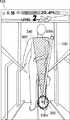
図1は、本実施形態にかかる歩行訓練装置100の概略斜視図である。歩行訓練装置100は、歩行訓練システムの一例であり、一方の脚に麻痺を患う片麻痺患者である訓練者900が、歩行訓練を行うための装置である。歩行訓練装置100は、主に、全体の骨格を成すフレーム130に取り付けられた制御盤133と、訓練者900が歩行するトレッドミル131と、訓練者900の麻痺側の脚部である患脚に装着する歩行補助装置120とを備える。 FIG. 1 is a schematic perspective view of the
フレーム130は、床面に設置されるトレッドミル131上に立設されている。トレッドミル131は、不図示のモータによりリング状のベルト132を回転させる。トレッドミル131は、訓練者900の歩行を促す装置である。歩行訓練を行う訓練者900は、ベルト132に乗り、ベルト132の移動に合わせて歩行動作を試みる。 The
フレーム130は、モータやセンサの制御を行う全体制御部210を収容する制御盤133や、訓練の進捗状況等を訓練者900へ呈示する例えば液晶パネルである訓練用モニタ138などを支持している。すなわち、訓練用モニタ138は、表示ユニットであり、訓練者900がトレッドミル131のベルト132上を歩行しながら視認できるように設置されている。また、フレーム130は、訓練者900の頭上部前方付近で前側引張部135を、頭上部付近でハーネス引張部112を、頭上部後方付近で後側引張部137支持している。また、フレーム130は、訓練者900が掴むための手摺り130aを含む。 The
カメラユニット140は、訓練者900の歩容が認識できる画角で訓練者を撮像する。本実施形態におけるカメラユニット140は、ベルト132上に立つ訓練者900の頭部を含む全身を捉えられる画角となるような、レンズと撮像素子のセットを含む。撮像素子は、例えばCMOSイメージセンサであり、結像面に結像した光学像を画像信号に変換する。カメラユニット140は、訓練用モニタ138の近傍に、訓練者900と相対するように設置されている。 The
前側ワイヤ134は、一端が前側引張部135の巻取機構に連結されており、他端が歩行補助装置120に連結されている。前側引張部135の巻取機構は、不図示のモータをオン/オフさせることにより、患脚の動きに応じて前側ワイヤ134を巻き取ったり繰り出したりする。同様に、後側ワイヤ136は、一端が後側引張部137の巻取機構に連結されており、他端が歩行補助装置120に連結されている。後側引張部137の巻取機構は、不図示のモータをオン/オフさせることにより、患脚の動きに応じて後側ワイヤ136を巻き取ったり繰り出したりする。このような前側引張部135と後側引張部137の連携した動作により、歩行補助装置120の荷重が患脚の負担とならないように当該荷重を相殺し、更には、設定の程度に応じて患脚の振り出し動作をアシストする。 One end of the
例えば、訓練補助者であるオペレータは、重度の麻痺を抱える訓練者に対しては、アシストするレベルを大きく設定する。アシストするレベルが大きく設定されると、前側引張部135は、患脚の振り出しタイミングに合わせて、比較的大きな力で前側ワイヤ134を巻き取る。訓練が進み、アシストが必要でなくなったら、オペレータは、アシストするレベルを最小に設定する。アシストするレベルが最小に設定されると、前側引張部135は、患脚の振り出しタイミングに合わせて、歩行補助装置120の自重をキャンセルするだけの力で前側ワイヤ134を巻き取る。 For example, an operator who is a training assistant sets a large level of assistance for a trainee who has severe paralysis. When the assist level is set to a large value, the
歩行訓練装置100は、装具110、ハーネスワイヤ111、ハーネス引張部112を主な構成要素とする安全装置を備える。装具110は、訓練者900の腹部に巻き付けられるベルトであり、例えば面ファスナによって腰部に固定される。ハーネスワイヤ111は、一端が装具110に連結されており、他端がハーネス引張部112の巻取機構に連結されている。ハーネス引張部112の巻取機構は、不図示のモータをオン/オフさせることにより、ハーネスワイヤ111を巻き取ったり繰り出したりする。このような構成により、安全装置は、訓練者900が体勢を大きく崩した場合に、その動きを検知した全体制御部210の指示に従ってハーネスワイヤ111を巻き取り、装具110により訓練者900の上体を支える。 The walking
管理用モニタ139は、フレーム130に取り付けられており、主にオペレータが監視および操作するための表示入力装置である。管理用モニタ139は、例えば液晶パネルであり、その表面にはタッチパネルが設けられている。管理用モニタ139は、訓練設定に関する各種メニュー項目や、訓練時における各種パラメータ値、訓練結果などを呈示する。 The
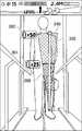
歩行補助装置120は、訓練者900の患脚に装着され、患脚の膝関節における伸展および屈曲の負荷を軽減することにより訓練者900の歩行を補助する。図2は、歩行補助装置120の概略斜視図である。歩行補助装置120は、主に、制御ユニット121と、患脚の各部を支える複数のフレームと、足裏に掛かる荷重を検出するための荷重センサ222とを備える。 The walking
制御ユニット121は、歩行補助装置120の制御を行う補助制御部220を含み、また、膝関節の伸展運動および屈曲運動を補助するための駆動力を発生させる不図示のモータを含む。患脚の各部を支えるフレームは、上腿フレーム122と、上腿フレーム122に回動自在に連結された下腿フレーム123と、下腿フレーム123に回動自在に連結された足平フレーム124と、前側ワイヤ134を連結するための前側連結フレーム127と、後側ワイヤ136を連結するための後側連結フレーム128とを含む。前側連結フレーム127は、上腿の前側を左右方向に伸延し、両端で上腿フレーム122に接続するように設けられている。後側連結フレーム128は、下腿の後側を左右方向に伸延し、両端でそれぞれ上下に伸延する下腿フレーム123に接続するように設けられている。 The
上腿フレーム122と下腿フレーム123は、図示するヒンジ軸Ha周りに相対的に回動する。制御ユニット121のモータは、補助制御部220の指示に従って回転して、上腿フレーム122と下腿フレーム123がヒンジ軸Ha周りに相対的に開くように加勢したり、閉じるように加勢したりする。制御ユニット121に収められた角度センサ223は、例えばロータリエンコーダであり、ヒンジ軸Ha周りの上腿フレーム122と下腿フレーム123の成す角を検出する。下腿フレーム123と足平フレーム124は、図示するヒンジ軸Hb周りに相対的に回動する。相対的に回動する角度範囲は、調整機構126によって事前に調整される。
上腿フレーム122は、上腿ベルト129を備える。上腿ベルト129は、上腿フレームに一体的に設けられたベルトであり、患脚の上腿部に巻き付けて上腿フレーム122を上腿部に固定する。これにより、歩行補助装置120の全体が訓練者900の脚部に対してずれることを防止している。 The
荷重センサ222は、足平フレーム124に埋め込まれた荷重センサである。荷重センサ222は、訓練者900の足裏が受ける垂直荷重の大きさと分布を検出する。荷重センサ222は、例えば、電極がマトリックス状に配置された抵抗変化検出型の荷重検出シートである。 The
次に歩行訓練装置100のシステム構成について説明する。図3は、歩行訓練装置100のシステム構成図である。全体制御部210は、例えばMPUであり、システムメモリから読み込んだ制御プログラムを実行することにより、装置全体の制御を実行する。トレッドミル駆動部211は、ベルト132を回転させるモータとその駆動回路を含む。全体制御部210は、トレッドミル駆動部211へ駆動信号を送ることにより、ベルト132の回転制御を実行する。例えば、設定された訓練レベルに応じて、ベルト132の回転速度を調整する。 Next, the system configuration of the walking
操作受付部212は、訓練者900やオペレータからの入力操作を受け付けて、操作信号を全体制御部210へ送信する。訓練者900やオペレータは、操作受付部212を構成する操作ボタンや管理用モニタ139に重畳されたタッチパネル、付属するリモコン等を操作して、電源のオン/オフやトレーニングの開始の指示を与えたり、設定に関する数値の入力やメニュー項目の選択を行ったりする。 The
表示制御部213は、全体制御部210からの制御信号に従って表示映像を生成し、訓練用モニタ138または管理用モニタ139に表示する。表示制御部213は、トレーニングの進捗を示す映像等を生成する。具体的には後に詳述するが、表示制御部213は、歩行訓練を行う訓練者900の体幹の傾きに対応する体幹ラインと、当該体幹ラインのフレが許容される範囲を示す指標を、コンピュータグラフィックス(CG)として訓練用モニタ138へ表示する。 The
引張駆動部214は、前側ワイヤ134を引張するためのモータとその駆動回路と、後側ワイヤ136を引張するためのモータとその駆動回路とを含む。全体制御部210は、引張駆動部214へ駆動信号を送ることにより、前側ワイヤ134の巻き取りと後側ワイヤ136の巻き取りをそれぞれ制御する。また、巻き取り動作に限らず、モータの駆動トルクを制御することにより、各ワイヤの引張力を制御する。全体制御部210は、例えば、荷重センサ222の検出結果から患脚が立脚状態から遊脚状態に切り替わるタイミングを同定し、そのタイミングに同期して各ワイヤの引張力を増減させることにより、患脚の振り出し動作をアシストする。 The
ハーネス駆動部215は、ハーネスワイヤ111を引張するためのモータとその駆動回路を含む。全体制御部210は、ハーネス駆動部215へ駆動信号を送ることにより、ハーネスワイヤ111の巻き取りと、ハーネスワイヤ111の引張力を制御する。全体制御部210は、例えば、訓練者900が体勢を大きく崩した場合に、ハーネスワイヤ111を一定量巻き取って、訓練者の転倒を防止する。 The
画像処理部216は、全体制御部210からの制御信号に従って、カメラユニット140から受け取った画像信号を画像処理して画像データを生成する。また、画像処理部216は、全体制御部210からの指示に従って、カメラユニット140から受け取った画像信号に画像処理を施して、特定の画像解析を実行することもできる。例えば、抽出されたエッジ等の情報から、両肩位置や股関節位置を検出することができる。これらの位置情報は、後述する体幹演算の入力情報となる。同様に、取得した画像内における患脚の踵近傍位置を検出することができる。このような情報は、CGを描画する位置の決定に利用される。 The
カメラユニット140は、全体制御部210からの制御信号に従って撮像動作を繰り返し、画像処理部216へ画像信号を出力する。グラフィックDB217は、訓練用モニタ138または管理用モニタ139に表示されるCG素材が格納されている。全体制御部210は、各モニタへ表示させるCG素材をグラフィックDB217から読み出して、表示制御部213へ引き渡す。表示制御部213は、受け取ったCG素材に拡大処理、回転処理等を施して所定位置へ配置し、表示映像を生成する。 The
全体制御部210は、制御に関わる様々な演算や制御を実行する機能実行部としての役割も担う。体幹演算部210aは、カメラユニット140が撮像した訓練者画像を画像処理部216が解析した結果を受けて、歩行中である訓練者900の体幹の傾きを演算する。具体的には、画像処理部216が解析した両肩位置や股関節位置などの主要骨格の基準位置を接続して画像中の体幹を決定し、当該体幹の伸延方向と歩行面の鉛直軸が成す角を傾斜角として演算する。歩容評価部210bは、体幹演算部210aが演算した体幹の傾きを用いて訓練者900の歩容を評価する。歩容評価部210bは、画像処理部216による画像解析や荷重センサ222、距離センサ等のセンサ出力から検出される引摺り歩行や躓き、手摺り130aの把持等についても、評価の対象として考慮することもできる。距離センサとしては、測定対象にパターン光を投射してその歪み具合から複数のポイントの距離を取得するデプスセンサ等を利用し得る。 The
上述のように、歩行補助装置120は訓練者900の患脚に装着されるが、歩行訓練装置100は、歩行補助装置120に指令を与えたり、センサ情報を受け取ったりするために、全体制御部210に接続された通信接続IF219を備える。歩行補助装置120も、通信接続IF219と有線または無線によって接続される通信接続IF229が設けられている。通信接続IF229は、歩行補助装置120の補助制御部220に接続されている。通信接続IF219、229は、通信規格に則った例えば無線LAN等の通信インタフェースである。 As described above, the walking assist
補助制御部220は、例えばMPUであり、全体制御部210から与えられた制御プログラムを実行することにより、歩行補助装置120の制御を実行する。また、歩行補助装置120の状態を、通信接続IF219、229を介して全体制御部210へ通知する。また、全体制御部210からの指令を受けて、歩行補助装置120の起動/停止等を実行する。 The
関節駆動部221は、制御ユニット121のモータとその駆動回路を含む。補助制御部220は、関節駆動部221へ駆動信号を送ることにより、上腿フレーム122と下腿フレーム123がヒンジ軸Ha周りに相対的に開くように加勢したり、閉じるように加勢したりする。このような動作により、膝の伸展動作および屈曲動作をアシストしたり、膝折れを防止したりする。荷重センサ222は、上述の通り訓練者900の足裏が受ける垂直荷重の大きさと分布を検出して、検出信号を補助制御部220へ送信する。The
補助制御部220は、検出信号を受け取り解析することにより、遊脚/立脚の状態判別や切替り推定等を行う。角度センサ223は、上述の通りヒンジ軸Ha周りの上腿フレーム122と下腿フレーム123の成す角を検出して、検出信号を補助制御部220へ送信する。補助制御部220は、検出信号を受け取って膝関節の開き角を演算する。The
本実施形態における歩行訓練装置100は、訓練者900が楽しみながら歩行訓練を行えるよう、訓練試行にはゲーム性が取り入れられている。具体的には、訓練計画に沿って設定された各目標状態を達成できるように、訓練者が、ふらつくことなく一定の歩容を保って歩行すれば、訓練プログラムは当該訓練試行に対して高得点を与える。しかも、訓練の進行に従って、動的かつリアルタイムに視覚効果を与え、得点情報を更新する。以下に、訓練試行時における訓練用モニタ138の表示例をいくつか説明する。 In the
図4は、訓練者900の歩容が正常である場合の訓練用モニタ138の表示例である。訓練用モニタ138の最上部にはステータス領域310が設けられており、訓練試行におけるステータス情報が表示されている。ステータス情報は、試行継続時間、歩行距離、訓練レベル、得点インジケータ等を含む。試行継続時間は、試行開始からの時間であり、継続時間は、不図示のタイマーによって計測される。歩行距離は、トレッドミル駆動部211がベルト123を回転させた積算量から計測される。訓練レベルは、訓練試行の難易度を表わし、予め設定された基準を満たすごとに更新される。訓練試行の難易度は、ベルト123の回転速度や歩行補助装置120のアシスト量によって規定されている。訓練開始時の訓練レベルは、訓練者900の状態に合わせて、療法士等である訓練補助者によって設定される。得点インジケータは、後述する獲得ポイントの加算、減算に応じて増減される。 FIG. 4 is a display example of the
訓練用モニタ138のうちステータス領域310以外の領域には、カメラ画像320が映し出されている。カメラ画像320は、カメラユニット140によって撮像された訓練者900の全身画像であり、例えば60fpsのリアルタイム映像として表示される。訓練者900は、訓練試行中の自身の姿をリアルタイム映像として確認することができる。なお、訓練者900は訓練用モニタ138に相対しているので、カメラ画像320は、視認性の観点から、図示するように鏡像反転されていることが好ましい。 A
カメラ画像320には、体幹演算部210aによって演算された体幹の傾きに対応する体幹ライン330と、体幹ライン330のフレが許容される範囲を示すフレ指標340とが、それぞれCGとして重畳されている。本実施形態においては、体幹ライン330は、訓練者900の患脚の踵近傍を基点330aとして肩付近まで伸延する直線ポール状のCGで表現されている。肩付近の端点330bは、体幹のフレを視認しやすいように、若干の装飾が施されている。 In the
体幹ライン330は、訓練者900がベルト123上にまっすぐ立っているのであれば、基点330aから端点330bまで、ベルト123の面に対して垂直に描画される。また、訓練者900の体幹が歩行に伴って揺れ動けば、体幹ライン330は、その傾きの角度に応じて、基点330a周りに揺れ動く。なお、基点330aは患脚の踵近傍位置に定められるので、体幹ライン330の全体が患脚の動き(立脚や遊脚)に応じて移動する。歩行訓練を行う訓練者900にとっては、不調となる体幹の傾きが主に患脚の状態によって生じるので、体幹ライン330が患脚の踵近傍位置を基点として描画されていると、因果関係の認識において感覚と良く整合する。また、体幹ライン330を踵近傍から肩付近まで描画すれば、訓練用モニタ138の表示領域において比較的大きなオブジェクトとなるので、視認性が向上する。 The
フレ指標340は、体幹ライン330の基点330aを要とする扇形形状として描画される。扇形形状の弧の部分は、体幹ライン330の端点330bの揺動方向に沿うように描画される。また、扇形状の中心角は、体幹ライン330のフレが許容される範囲に従って決定される。フレ指標340は、例えば薄く着色された半透過状に描画されることが好ましい。半透過状に描画されれば訓練者900の姿が大きく隠れることがないので、訓練者900は、自身の状態をより正しく確認することができる。フレが許容される範囲は、訓練レベルごとに予め設定されている。訓練レベルが低いうちは大きく設定され、訓練レベルが高くなるに従って徐々に小さく設定される。 The
このようにフレ指標340を扇形形状で描画されていると、訓練者900は、運脚に応じて揺れ動く体幹ライン330が扇形形状の内側に収まっていればその訓練試行において許容される歩容であると認識することができる。なお、訓練者900は、体幹ライン330の全体を注視しなくても、例えば端点330bが扇形の弧上に存在するかを一瞥すれば、現在の体幹の傾きが許容範囲であるかを認識することができる。このような描画は、訓練試行中に補助者を見たり足元を見たりする訓練者900にとっては都合が良い。上述のように、体幹ライン330およびフレ指標340は、体幹演算部210aの演算に基づいて描画されるものであり、訓練者900とは区別して視認されるものである。 When the
図5は、訓練者900の歩容に不調が生じた場合の訓練用モニタ138の表示例である。歩容評価部210bが評価する訓練者900の歩容の不調には様々な種類があるが、ここでは、その代表例である体幹の異常傾きについて説明する。 FIG. 5 is a display example of the
歩容評価部210bは、体幹演算部210aが演算した訓練者900の体幹の傾きが、設定されているフレ許容範囲に収まっているか否かを判断し、収まっていない場合には歩容不調と評価する。このように不調が検出されると、体幹ライン330の基点330aの近傍に、不調を示すオブジェクトである不調オブジェクト350が表示される。不調オブジェクト350は、図においては破裂を示唆する図形として表わしているが、不調の程度や原因によって異なるオブジェクトを表示しても良く、アニメーションを伴っても良い。このように、歩容の不調を生じさせている主な原因である患脚の踵近傍にオブジェクトを表示すれば、訓練者900は、好ましくない歩容であったことを、より直感的に把握できる。 The gait evaluation unit 210b determines whether or not the inclination of the
また、体幹ライン330は、体幹演算部210aが演算した訓練者900の体幹の傾きに応じて基点330a周りに傾けて表示されるので、設定されているフレ許容範囲に収まっていない場合にはフレ指標340の外縁を超えて傾いて描画される。すなわち、端点330bは、フレ指標340の弧から離れて描画される。このように、訓練者900の体幹の傾きに対応する体幹ライン330と、体幹ライン330のフレが許容される範囲の端を視認させるフレ指標340のような指標とを同時に訓練用モニタ138に表示すれば、訓練者900は、自身の状況を容易に認識できる。すなわち、訓練者900は、片麻痺を患っていたり歩行補助装置120を装着したりして右脚と左脚で動きやすさが異なる状況でありながら、歩行訓練の試行中に、許容される体のフレ範囲に対して自身の体がどれくらい傾いているのか、直感的に把握することができる。 Further, since the
本実施形態における歩行訓練装置100は、歩行訓練にゲーム性を与えている。ゲーム性に関する表示について説明する。図6は、訓練試行の進捗状況を示す表示例である。図5の表示例では、歩容評価部210bの評価結果として不調オブジェクト350が表示されたが、図6の表示例では、ゲーム性を付与するために、歩容評価部210bの評価結果を獲得ポイントに換算し、その獲得ポイントに応じたオブジェクトが表示される。 The walking
具体的には、フレ指標340の扇形形状に内包される達成インジケータ360が、歩容評価部210bの評価結果に応じて増減するように表示される。また、現時点の達成度合が一瞥で認識できるように、達成インジケータ360に隣接してポイント指標361が表示される。また、どれくらいのポイントを獲得すれば現在のレベルをクリアできるかを認識できるように、フレ指標340の頂上部近傍にクリア指標362が表示される。ポイント指標361とクリア指標362は、図示するように、例えばポイントを示すアイコンと数値で描画される。 Specifically, the
獲得ポイントは、一定時間(例えば1秒)の間継続して体幹ライン330がフレ指標340の範囲に収まっていれば加算され、達成インジケータ360は、フレ指標340の弧へ向かって拡大される。獲得ポイントは、運脚が周期的であるなど他の評価ポイントによっても加算され得る。一方で、獲得ポイントは、体幹ライン330がフレ指標340の範囲から逸脱すると減算され、達成インジケータ360は、フレ指標340の要へ向かって縮小される。獲得ポイントは、引摺りを検出した場合など他の評価ポイントによっても減算され得る。 The earned points are added if the
図7は、訓練試行のイベントクリアを示す表示例である。訓練試行中に、獲得ポイントがクリアポイントに到達すると、すなわち達成インジケータ360の全量が表示された場合に、その時点でのレベルはクリアしたものと評価して、レベルクリアのイベント表示が実行される。イベント表示は、例えばアニメーションとして変化する「LEVEL UP!」の文字列や、きらめきを表現する十字図形からなるイベントオブジェクト370の描画によって行われる。このようなイベント表示を実行することにより、歩行訓練にゲーム性を付与することができ、訓練者900は、より楽しく歩行訓練を行うことができる。 FIG. 7 is a display example showing the event clearing of the training trial. During the training trial, when the earned points reach the clear points, that is, when the total amount of the
次に、訓練試行における表示処理の処理フローについて説明する。図8は、一回の訓練試行における表示処理の処理フローを示す図である。図示するフローは、訓練試行が開始されてベルト132が動き始めた状態から開始される。 Next, the processing flow of the display processing in the training trial will be described. FIG. 8 is a diagram showing a processing flow of display processing in one training trial. The flow shown is started from the state where the training trial is started and the
全体制御部210は、ステップS101で、カメラユニット140に撮像処理を行わせて訓練者900が映るフレーム画像を取得する。画像処理部216は、カメラユニット140が出力したフレーム画像を受け取って画像処理し、さらに、両肩位置や股関節位置等を検出する画像解析を実行する。 In step S101, the
体幹演算部210aは、ステップS102で、画像処理部216が検出した両肩位置や股関節位置等を受け取り、訓練者900の体幹の傾きを演算する。歩容評価部210bは、ステップS103で、体幹演算部210aが演算した体幹の傾きを受け取り、当該傾きがフレ許容範囲に収まっているか否かを判断して、訓練者900の歩容を評価する。 In step S102, the
表示制御部213は、ステップS104で、画像処理部216によって画像処理された訓練者900のフレーム画像に、演算された体幹の傾きに応じた体幹ライン330、フレ指標340、その他表示すべきオブジェクトを重畳して表示映像を調整する。このように調整された表示映像は、訓練用モニタ138に送られ、それまでに表示されていた映像が更新される。ステップS105へ進み、表示制御部213は、獲得ポイントがクリアポイントに到達しているか否かを確認する。到達していれば、レベルクリアのイベント表示を実行(ステップS106)してからステップS107へ進む。到達していなければ、ステップS106をスキップしてステップS107へ進む。 In step S104, the
全体制御部210は、ステップS107で、試行訓練が終了したか否かを判断する。例えば訓練時間や歩行距離、目標レベルへの到達が、予め終了条件として設定されている。終了していないと判断した場合は、ステップS101へ戻り、訓練試行を継続する。終了したと判断した場合は、ステップS108へ進む。表示制御部213は、ステップS108で、訓練試行の結果を表示する。訓練試行の結果は、例えば、歩行距離、獲得総ポイント、到達レベル、評価コメントを含む。全体制御部210は、表示制御部213が結果表示を行ったら、一連の処理を終了させる。 In step S107, the
以上に説明した本実施形態においては、フレ指標340を、体幹ライン330の基点330aを要とする扇形形状として描画したが、フレ指標はこれに限らず、様々に描画し得る。以下に他の例を説明する。図9は、訓練用モニタ138の他の表示例である。 In the present embodiment described above, the
フレ指標440は、円弧とその両端の境界によって構成されている。両端の境界に挟まれた円弧の範囲がフレ許容範囲である。訓練者900は、体幹ライン330の端点330bが円弧上に存在している間は体幹の傾きが許容された範囲に収まっていると認識することができる。よりシンプルなフレ指標を採用するのであれば、円弧部分を描画することなくフレ許容範囲の両端を示す境界のみをフレ指標としても良い。 The
図10は、訓練用モニタ138のさらに他の表示例である。フレ指標540は、フレ指標の構成としては図9に示すフレ指標440と同様である。しかし、ここでは実際のフレ角に対して2倍の角度で揺動する体幹ライン530が採用されており、これに合わせて、フレ指標540のフレ許容範囲も2倍の長さで描画されている。したがって、体幹ライン330は、実際の体幹の傾き(点線で示す傾き)よりも大きく傾くので、訓練者900は自身の体幹の傾きをより敏感に認識することができる。もちろん、拡大率は2倍に限らず、例えば訓練段階に応じて適宜選択できるようにしても構わない。訓練が進んで体幹の傾きが小さくなってきた段階で、このような表示形式を選択すると良い。逆に、訓練の初期段階で体幹が大きく傾いてしまうような場合には、1より小さい拡大率で体幹ライン530を揺動させ、これに合わせてフレ指標540のフレ許容範囲も短く描画しても良い。 FIG. 10 is still another display example of the
以上説明した実施形態においては、体幹ラインを直線ポール状のCGとして描画したが、体幹の傾きに対応する角度が認識される態様であれば、いかなる描画であっても構わない。また、体幹ラインの基点を患脚の踵近傍としたが、これに限らず、例えば、接地した足が基点となるように運脚に合わせて描画しても良い。また、本実施形態においては、訓練者900を正面から観察した場合の体幹の傾きについて説明したが、側方から訓練者900を撮像するようにカメラユニット140を設置し、運脚の前後方向における体幹の傾きについて同様の表示を行っても良い。あるいは、正面からと側方からのそれぞれの体幹の傾きを並列で評価して、分割表示によって、あるいは交互表示によって正面からと側方からの映像表示を行っても良い。 In the embodiment described above, the trunk line is drawn as a straight pole-shaped CG, but any drawing may be used as long as the angle corresponding to the inclination of the trunk is recognized. Further, the base point of the trunk line is set near the heel of the affected leg, but the drawing is not limited to this, and for example, the drawing may be performed according to the leg so that the grounded foot becomes the base point. Further, in the present embodiment, the inclination of the trunk when the
また、以上説明した実施形態においては、カメラユニット140が撮像した訓練者900の画像に体幹ラインとフレ指標を重畳して表示したが、重畳させることなく、例えば体幹ラインとフレ指標は別ウィンドウで表示しても構わない。また、訓練者の画像を直接的に表示するのではなく、訓練者の姿を例えばCGキャラクタに変換してアニメーションで表示しても構わない。訓練者によっては、自身の姿を観察したくないという事情もあり得るので、様々な表示態様を選択できるように構成すると良い。 Further, in the embodiment described above, the trunk line and the frame index are superimposed and displayed on the image of the
また、歩行訓練システムは、それぞれの機能要素のすべてが歩行訓練装置100に集約された構成でなくても良い。例えば、体幹演算部210aの機能は、歩行訓練装置100とネットワークを介して接続されたサーバが備える演算部が担っても良い。この場合、サーバは、演算した体幹の傾きを歩行訓練装置100へ送信する。歩行訓練装置100の全体制御部210は、送られてきた体幹の傾きを利用して、上述の実施形態と同様の表示を実現する。このように、サーバと歩行訓練装置100を含むように歩行訓練システムを構成しても良い。 Further, the walking training system does not have to have all the functional elements integrated in the
100 歩行訓練装置、110 装具、111 ハーネスワイヤ、112 ハーネス引張部、120 歩行補助装置、121 制御ユニット、122 上腿フレーム、123 下腿フレーム、124 足平フレーム、126 調整機構、127 前側連結フレーム、128 後側連結フレーム、129 上腿ベルト、130 フレーム、130a 手摺り、131 トレッドミル、132 ベルト、133 制御盤、134 前側ワイヤ、135 前側引張部、136 後側ワイヤ、137 後側引張部、138 訓練用モニタ、139 管理用モニタ、140 カメラユニット、210 全体制御部、210a 体幹演算部、210b 歩容評価部、211 トレッドミル駆動部、212 操作受付部、213 表示制御部、214 引張駆動部、215 ハーネス駆動部、216 画像処理部、217 グラフィックDB、219 通信接続IF、220 補助制御部、221 関節駆動部、222 荷重センサ、223 角度センサ、229 通信接続IF、310 ステータス領域、320 カメラ画像、330、530 体幹ライン、340、440、540 フレ指標、350 不調オブジェクト、360 達成インジケータ、361 ポイント指標、362 クリア指標、370 イベントオブジェクト、900 訓練者100 gait training device, 110 equipment, 111 harness wire, 112 harness tension part, 120 gait assist device, 121 control unit, 122 upper leg frame, 123 lower leg frame, 124 foot flat frame, 126 adjustment mechanism, 127 front connecting frame, 128 Rear connecting frame, 129 upper leg belt, 130 frame, 130a handrail, 131 treadmill, 132 belt, 133 control panel, 134 front wire, 135 front tension part, 136 rear wire, 137 rear tension part, 138 training Monitor, 139 management monitor, 140 camera unit, 210 overall control unit, 210a trunk calculation unit, 210b gait evaluation unit, 211 treadmill drive unit, 212 operation reception unit, 213 display control unit, 214 tension drive unit, 215 Harness drive unit, 216 image processing unit, 217 graphic DB, 219 communication connection IF, 220 auxiliary control unit, 221 joint drive unit, 222 load sensor, 223 angle sensor, 229 communication connection IF, 310 status area, 320 camera image, 330, 530 trunk line, 340, 440, 540 frame index, 350 upset object, 360 achievement indicator, 361 point index, 362 clear index, 370 event object, 900 trainee
Claims (9)
Translated fromJapanese前記訓練者が前記トレッドミル上を歩行しながら視認できるように設置された表示ユニットと、
前記訓練者の歩容が認識できる画角で前記訓練者を撮像するカメラユニットと、
前記カメラユニットで撮像した画像に基づいて歩行中における前記訓練者の体幹の傾きを演算する演算部と、
前記傾きに対応する体幹ライン、および前記体幹ラインのフレが許容される範囲の少なくとも端を示す指標を前記表示ユニットに表示する表示制御部と
を備える歩行訓練システム。A treadmill that encourages trainees to walk,
A display unit installed so that the trainee can visually recognize while walking on the treadmill.
A camera unit that captures the trainee at an angle of view that allows the trainee's gait to be recognized, and
An arithmetic unit that calculates the inclination of the trainee's trunk during walking based on the image captured by the camera unit, and
A walking training system including a trunk line corresponding to the inclination and a display control unit that displays an index indicating at least an end of a range in which the fluctuation of the trunk line is allowed on the display unit.
前記表示制御部は、前記評価部の評価結果に基づくオブジェクトを表示する請求項4に記載の歩行訓練システム。Equipped with an evaluation unit that evaluates the gait
The walking training system according to claim 4, wherein the display control unit displays an object based on the evaluation result of the evaluation unit.
前記カメラユニットで撮像した画像に基づいて歩行中における前記訓練者の体幹の傾きを演算する演算ステップと、
前記傾きに対応する体幹ライン、および前記体幹ラインのフレが許容される範囲の少なくとも端を示す指標を前記表示ユニットに表示する表示ステップと
をコンピュータに実行させる歩行訓練システムの制御プログラム。The trainee is imaged with a treadmill that encourages the trainee to walk, a display unit that is installed so that the trainee can visually recognize the trainee while walking on the treadmill, and an angle at which the trainee's gait can be recognized. It is a control program of a walking training system equipped with a treadmill.
A calculation step for calculating the inclination of the trainee's trunk during walking based on the image captured by the camera unit, and
A control program of a walking training system that causes a computer to execute a trunk line corresponding to the inclination and a display step of displaying an index indicating at least an end of a range in which the fluctuation of the trunk line is allowed on the display unit.
Priority Applications (4)
| Application Number | Priority Date | Filing Date | Title |
|---|---|---|---|
| JP2019106942AJP7120162B2 (en) | 2019-06-07 | 2019-06-07 | Gait training system and control program for the gait training system |
| US16/885,855US11565165B2 (en) | 2019-06-07 | 2020-05-28 | Walking training system, non-transitory storage medium storing control program for walking training system and control method for walking training system |
| CN202010504154.XACN112053766B (en) | 2019-06-07 | 2020-06-05 | Walking training system, storage medium storing control program for walking training system, and method for controlling walking training system |
| EP20178586.2AEP3747361B1 (en) | 2019-06-07 | 2020-06-05 | Walking training system, non-transitory storage medium storing control program for walking training system and control method for walking training system |
Applications Claiming Priority (1)
| Application Number | Priority Date | Filing Date | Title |
|---|---|---|---|
| JP2019106942AJP7120162B2 (en) | 2019-06-07 | 2019-06-07 | Gait training system and control program for the gait training system |
Publications (2)
| Publication Number | Publication Date |
|---|---|
| JP2020198994Atrue JP2020198994A (en) | 2020-12-17 |
| JP7120162B2 JP7120162B2 (en) | 2022-08-17 |
Family
ID=71016465
Family Applications (1)
| Application Number | Title | Priority Date | Filing Date |
|---|---|---|---|
| JP2019106942AActiveJP7120162B2 (en) | 2019-06-07 | 2019-06-07 | Gait training system and control program for the gait training system |
Country Status (4)
| Country | Link |
|---|---|
| US (1) | US11565165B2 (en) |
| EP (1) | EP3747361B1 (en) |
| JP (1) | JP7120162B2 (en) |
| CN (1) | CN112053766B (en) |
Families Citing this family (9)
| Publication number | Priority date | Publication date | Assignee | Title |
|---|---|---|---|---|
| US11557215B2 (en)* | 2018-08-07 | 2023-01-17 | Physera, Inc. | Classification of musculoskeletal form using machine learning model |
| JP6901809B1 (en)* | 2020-12-25 | 2021-07-14 | 株式会社ケアスマイル青森 | Activities of daily living improvement support device |
| US20220262010A1 (en)* | 2021-02-17 | 2022-08-18 | Ember Tech LLC | Biomechanical tracking and feedback system |
| JP7537374B2 (en)* | 2021-06-15 | 2024-08-21 | トヨタ自動車株式会社 | Walking condition measurement system |
| JP7548133B2 (en)* | 2021-06-16 | 2024-09-10 | トヨタ自動車株式会社 | Walking Training System |
| JP7635666B2 (en)* | 2021-07-26 | 2025-02-26 | トヨタ自動車株式会社 | Management system, method and program |
| WO2023049301A1 (en)* | 2021-09-22 | 2023-03-30 | Atlas Devices Llc | Adjustable weight distribution for protective suits |
| CN114927196A (en)* | 2022-04-27 | 2022-08-19 | 中国康复研究中心 | Evaluation system for gait training under assistance of child robot |
| CN120032428B (en)* | 2025-04-22 | 2025-07-11 | 四川中能鸿达智能装备有限公司 | A serpentine running training and assessment system based on visual recognition technology |
Citations (4)
| Publication number | Priority date | Publication date | Assignee | Title |
|---|---|---|---|---|
| JP2012081089A (en)* | 2010-10-12 | 2012-04-26 | Canon Inc | Image information processor and method |
| JP2013066696A (en)* | 2011-09-06 | 2013-04-18 | Gifu Univ | Image processing system and image processing method |
| JP2016154647A (en)* | 2015-02-24 | 2016-09-01 | セイコーエプソン株式会社 | Display device, display method, and program |
| JP2017051365A (en)* | 2015-09-08 | 2017-03-16 | トヨタ自動車株式会社 | Walking training apparatus and walking training method |
Family Cites Families (9)
| Publication number | Priority date | Publication date | Assignee | Title |
|---|---|---|---|---|
| JP5001580B2 (en)* | 2006-05-24 | 2012-08-15 | アニマ株式会社 | Body measuring device |
| JP5386253B2 (en) | 2009-07-15 | 2014-01-15 | サンコールエンジニアリング株式会社 | Walking diagnosis support system, walking pattern generation device, walking pattern generation program, and walking pattern generation method |
| JP5399987B2 (en)* | 2010-06-24 | 2014-01-29 | パナソニック株式会社 | Weighted training system |
| EP2649588A4 (en)* | 2010-12-07 | 2014-04-16 | Movement Training Systems Llc | Systems and methods for performance training |
| JP6334925B2 (en) | 2013-01-18 | 2018-05-30 | キヤノンメディカルシステムズ株式会社 | Motion information processing apparatus and method |
| JP2015225276A (en)* | 2014-05-29 | 2015-12-14 | セイコーエプソン株式会社 | Display system, display device, display control device, display method and program |
| JP6281444B2 (en)* | 2014-08-25 | 2018-02-21 | トヨタ自動車株式会社 | Walking training apparatus and control method thereof |
| JP2016179048A (en) | 2015-03-24 | 2016-10-13 | 国立大学法人埼玉大学 | Joint load visualization system |
| JP6468992B2 (en) | 2015-12-04 | 2019-02-13 | 日本電信電話株式会社 | Information presenting apparatus, information presenting method, and program |
- 2019
- 2019-06-07JPJP2019106942Apatent/JP7120162B2/enactiveActive
- 2020
- 2020-05-28USUS16/885,855patent/US11565165B2/enactiveActive
- 2020-06-05CNCN202010504154.XApatent/CN112053766B/enactiveActive
- 2020-06-05EPEP20178586.2Apatent/EP3747361B1/enactiveActive
Patent Citations (4)
| Publication number | Priority date | Publication date | Assignee | Title |
|---|---|---|---|---|
| JP2012081089A (en)* | 2010-10-12 | 2012-04-26 | Canon Inc | Image information processor and method |
| JP2013066696A (en)* | 2011-09-06 | 2013-04-18 | Gifu Univ | Image processing system and image processing method |
| JP2016154647A (en)* | 2015-02-24 | 2016-09-01 | セイコーエプソン株式会社 | Display device, display method, and program |
| JP2017051365A (en)* | 2015-09-08 | 2017-03-16 | トヨタ自動車株式会社 | Walking training apparatus and walking training method |
Also Published As
| Publication number | Publication date |
|---|---|
| CN112053766A (en) | 2020-12-08 |
| US11565165B2 (en) | 2023-01-31 |
| EP3747361B1 (en) | 2024-04-03 |
| US20200384342A1 (en) | 2020-12-10 |
| JP7120162B2 (en) | 2022-08-17 |
| EP3747361A1 (en) | 2020-12-09 |
| CN112053766B (en) | 2024-07-02 |
Similar Documents
| Publication | Publication Date | Title |
|---|---|---|
| JP7120162B2 (en) | Gait training system and control program for the gait training system | |
| JP6933101B2 (en) | Gait evaluation device, gait training system and gait evaluation method | |
| JP2020198993A (en) | Rehabilitation training system and rehabilitation training evaluation program | |
| JP7140063B2 (en) | SUPPORT MOTION MEASUREMENT SYSTEM, REHABILITATION SUPPORT SYSTEM, SUPPORT MOTION MEASUREMENT METHOD AND PROGRAM | |
| JP7020122B2 (en) | Walking training system | |
| JP7183963B2 (en) | Gait training system, display method, and display program | |
| JP7103307B2 (en) | Gait training system and control program of gait training system | |
| JP2022163994A (en) | Gait training system, and control method and control program thereof | |
| US20220406432A1 (en) | Walking training system, control method thereof, and control program | |
| JP2022190880A (en) | Walking training system, control method therefor, and control program | |
| JP7115622B2 (en) | Gait training system | |
| JP7115422B2 (en) | REHABILITATION TRAINING SYSTEM, REHABILITATION TRAINING SYSTEM CONTROL PROGRAM, AND REHABILITATION TRAINING SYSTEM CONTROL METHOD | |
| US20220331192A1 (en) | Walking training system, control method thereof, and control program | |
| JP7548868B2 (en) | Walking Training System | |
| JP2020198997A (en) | Training device | |
| US20220346668A1 (en) | Walking training system, control method thereof, and control program | |
| JP7115423B2 (en) | Gait training system, display method, and display program | |
| JP2025027182A (en) | Walking Training System | |
| JP2022191671A (en) | Walking training system, control method, and program | |
| JP2022175028A (en) | Walking condition measuring system, walking training system, walking condition measuring method and program | |
| JP2022185710A (en) | Walking training system, its control method, and control program |
Legal Events
| Date | Code | Title | Description |
|---|---|---|---|
| A621 | Written request for application examination | Free format text:JAPANESE INTERMEDIATE CODE: A621 Effective date:20210827 | |
| A977 | Report on retrieval | Free format text:JAPANESE INTERMEDIATE CODE: A971007 Effective date:20220413 | |
| A131 | Notification of reasons for refusal | Free format text:JAPANESE INTERMEDIATE CODE: A131 Effective date:20220419 | |
| A521 | Request for written amendment filed | Free format text:JAPANESE INTERMEDIATE CODE: A523 Effective date:20220524 | |
| TRDD | Decision of grant or rejection written | ||
| A01 | Written decision to grant a patent or to grant a registration (utility model) | Free format text:JAPANESE INTERMEDIATE CODE: A01 Effective date:20220705 | |
| A61 | First payment of annual fees (during grant procedure) | Free format text:JAPANESE INTERMEDIATE CODE: A61 Effective date:20220718 | |
| R151 | Written notification of patent or utility model registration | Ref document number:7120162 Country of ref document:JP Free format text:JAPANESE INTERMEDIATE CODE: R151 |