JP2020192394A - Pulse measuring element, pulse measuring device, and electronic apparatus - Google Patents
Pulse measuring element, pulse measuring device, and electronic apparatusDownload PDFInfo
- Publication number
- JP2020192394A JP2020192394AJP2020144999AJP2020144999AJP2020192394AJP 2020192394 AJP2020192394 AJP 2020192394AJP 2020144999 AJP2020144999 AJP 2020144999AJP 2020144999 AJP2020144999 AJP 2020144999AJP 2020192394 AJP2020192394 AJP 2020192394A
- Authority
- JP
- Japan
- Prior art keywords
- housing
- pulse measuring
- light guide
- light
- guide body
- Prior art date
- Legal status (The legal status is an assumption and is not a legal conclusion. Google has not performed a legal analysis and makes no representation as to the accuracy of the status listed.)
- Granted
Links
Images


Classifications
- A—HUMAN NECESSITIES
- A61—MEDICAL OR VETERINARY SCIENCE; HYGIENE
- A61B—DIAGNOSIS; SURGERY; IDENTIFICATION
- A61B5/00—Measuring for diagnostic purposes; Identification of persons
- A61B5/02—Detecting, measuring or recording for evaluating the cardiovascular system, e.g. pulse, heart rate, blood pressure or blood flow
- A61B5/024—Measuring pulse rate or heart rate
- A61B5/02416—Measuring pulse rate or heart rate using photoplethysmograph signals, e.g. generated by infrared radiation
- A61B5/02427—Details of sensor
- A—HUMAN NECESSITIES
- A61—MEDICAL OR VETERINARY SCIENCE; HYGIENE
- A61B—DIAGNOSIS; SURGERY; IDENTIFICATION
- A61B5/00—Measuring for diagnostic purposes; Identification of persons
- A61B5/02—Detecting, measuring or recording for evaluating the cardiovascular system, e.g. pulse, heart rate, blood pressure or blood flow
- A61B5/024—Measuring pulse rate or heart rate
- A61B5/02438—Measuring pulse rate or heart rate with portable devices, e.g. worn by the patient
- A—HUMAN NECESSITIES
- A61—MEDICAL OR VETERINARY SCIENCE; HYGIENE
- A61B—DIAGNOSIS; SURGERY; IDENTIFICATION
- A61B5/00—Measuring for diagnostic purposes; Identification of persons
- A61B5/68—Arrangements of detecting, measuring or recording means, e.g. sensors, in relation to patient
- A61B5/6801—Arrangements of detecting, measuring or recording means, e.g. sensors, in relation to patient specially adapted to be attached to or worn on the body surface
- A61B5/6802—Sensor mounted on worn items
- A61B5/681—Wristwatch-type devices
- A—HUMAN NECESSITIES
- A61—MEDICAL OR VETERINARY SCIENCE; HYGIENE
- A61B—DIAGNOSIS; SURGERY; IDENTIFICATION
- A61B2562/00—Details of sensors; Constructional details of sensor housings or probes; Accessories for sensors
- A61B2562/02—Details of sensors specially adapted for in-vivo measurements
- A61B2562/0233—Special features of optical sensors or probes classified in A61B5/00
- A61B2562/0238—Optical sensor arrangements for performing transmission measurements on body tissue
- A—HUMAN NECESSITIES
- A61—MEDICAL OR VETERINARY SCIENCE; HYGIENE
- A61B—DIAGNOSIS; SURGERY; IDENTIFICATION
- A61B5/00—Measuring for diagnostic purposes; Identification of persons
- A61B5/02—Detecting, measuring or recording for evaluating the cardiovascular system, e.g. pulse, heart rate, blood pressure or blood flow
- A61B5/024—Measuring pulse rate or heart rate
- A61B5/0245—Measuring pulse rate or heart rate by using sensing means generating electric signals, i.e. ECG signals
Landscapes
- Health & Medical Sciences (AREA)
- Life Sciences & Earth Sciences (AREA)
- Cardiology (AREA)
- Biomedical Technology (AREA)
- Medical Informatics (AREA)
- Biophysics (AREA)
- Pathology (AREA)
- Engineering & Computer Science (AREA)
- Veterinary Medicine (AREA)
- Heart & Thoracic Surgery (AREA)
- Physics & Mathematics (AREA)
- Molecular Biology (AREA)
- Surgery (AREA)
- Animal Behavior & Ethology (AREA)
- General Health & Medical Sciences (AREA)
- Public Health (AREA)
- Physiology (AREA)
- Measuring Pulse, Heart Rate, Blood Pressure Or Blood Flow (AREA)
Abstract
Translated fromJapaneseDescription
Translated fromJapanese本開示は、脈拍の計測に用いられる脈拍計測素子および脈拍計測装置、ならびにそのような脈拍計測素子を備えた電子機器に関する。 The present disclosure relates to a pulse measuring element and a pulse measuring device used for measuring a pulse, and an electronic device including such a pulse measuring element.
脈拍計測技術の1つに、光電容積脈波(PPG;Photoplethysmography)方式がある。
この光電容積脈波方式は、血中のヘモグロビンが光を吸収する性質を利用して血管の容積の変化を測定するものである。例えば、特許文献1,2には、発光素子から出射された光を、導光体を介して受光素子に導くように構成された脈拍計測装置が開示されている。この脈拍計測装置では、人体を導光体に接触させたときの、受光素子における受光量の変化に基づいて、脈拍情報を生成するようになっている。One of the pulse measurement techniques is a photoelectric volume pulse wave (PPG; Photoplethysmography) method.
This photoelectric volume pulse wave method measures a change in the volume of a blood vessel by utilizing the property that hemoglobin in blood absorbs light. For example,
一般に、計測装置では、計測精度が高いことが望まれる。しかしながら、上述した特許文献1,2には、発光素子、導光体、および受光素子をどのように筺体内に配置するのかが不明であり、その配置によっては計測精度が低くなるおそれがある。 In general, it is desired that the measuring device has high measurement accuracy. However, in the above-mentioned
計測精度を高めることができる脈拍計測素子、脈拍計測装置、および電子機器を提供することにある。 An object of the present invention is to provide a pulse measuring element, a pulse measuring device, and an electronic device capable of improving measurement accuracy.
本開示の一実施の形態における脈拍計測素子は、筺体と、発光素子と、受光素子と、導光体とを備えている。導光体は、発光素子と対向する第1の端面と、第1の端面と対向するとともに受光素子と対向する第2の端面と、筺体に覆われた1または複数の第1の側面と、筺体から露出された1または複数の第2の側面とを有するものである。上記導光体は、筐体と係合し、筐体から取り外し可能である。 The pulse measuring element according to the embodiment of the present disclosure includes a housing, a light emitting element, a light receiving element, and a light guide. The light guide includes a first end face facing the light emitting element, a second end face facing the first end face and facing the light receiving element, and one or more first side surfaces covered with a housing. It has one or more second sides exposed from the housing. The light guide body engages with the housing and is removable from the housing.
本開示の一実施の形態における脈拍計測装置は、脈拍計測素子と、信号処理部とを備えている。脈拍計測素子は、筺体と、発光素子と、受光素子と、導光体とを有している。導光体は、発光素子と対向する第1の端面と、第1の端面と対向するとともに受光素子と対向する第2の端面と、筺体に覆われた1または複数の第1の側面と、筺体から露出された1または複数の第2の側面とを含んでいる。信号処理部は、受光素子における受光量に基づいてユーザの脈拍情報を生成するものである。上記導光体は、筐体と係合し、筐体から取り外し可能である。 The pulse measuring device according to the embodiment of the present disclosure includes a pulse measuring element and a signal processing unit. The pulse measuring element includes a housing, a light emitting element, a light receiving element, and a light guide body. The light guide includes a first end face facing the light emitting element, a second end face facing the first end face and facing the light receiving element, and one or more first side surfaces covered with a housing. Includes one or more second sides exposed from the housing. The signal processing unit generates pulse information of the user based on the amount of light received by the light receiving element. The light guide body engages with the housing and is removable from the housing.
本開示の一実施の形態における電子機器は、脈拍計測素子と、信号処理部と、処理部とを備えている。脈拍計測素子は、筺体と、発光素子と、受光素子と、導光体とを有している。導光体は、発光素子と対向する第1の端面と、第1の端面と対向するとともに受光素子と対向する第2の端面と、筺体に覆われた1または複数の第1の側面と、筺体から露出された1または複数の第2の側面とを含んでいる。信号処理部は、受光素子における受光量に基づいてユーザの脈拍情報を生成するものである。処理部は、脈拍情報を用いて所定の処理を行うものである。上記導光体は、筐体と係合し、筐体から取り外し可能である。 The electronic device according to the embodiment of the present disclosure includes a pulse measuring element, a signal processing unit, and a processing unit. The pulse measuring element includes a housing, a light emitting element, a light receiving element, and a light guide body. The light guide includes a first end face facing the light emitting element, a second end face facing the first end face and facing the light receiving element, and one or more first side surfaces covered with a housing. Includes one or more second sides exposed from the housing. The signal processing unit generates pulse information of the user based on the amount of light received by the light receiving element. The processing unit performs a predetermined process using the pulse information. The light guide body engages with the housing and is removable from the housing.
本開示の一実施の形態における脈拍計測素子、脈拍計測装置、および電子機器では、発光素子から出射された光が第1の端面を介して導光体に入射される。また、導光体の第2の端面を介して出射された光は受光素子により受光される。導光体の1または複数の第1の側面は筺体に覆われ、1または複数の第2の側面は筺体から露出される。そして、導光体は、筐体と係合し、筐体から取り外し可能である。 In the pulse measuring element, the pulse measuring device, and the electronic device according to the embodiment of the present disclosure, the light emitted from the light emitting element is incident on the light guide through the first end face. Further, the light emitted through the second end surface of the light guide is received by the light receiving element. One or more first sides of the light guide are covered with a housing, and one or more second sides are exposed from the housing. Then, the light guide body engages with the housing and is removable from the housing.
本開示の一実施の形態における脈拍計測素子、脈拍計測装置、および電子機器によれば、導光体の1または複数の第1の側面が筺体に覆われ、1または複数の第2の側面が筺体から露出されるようにしたので、計測精度を高めることができる。なお、ここに記載された効果は必ずしも限定されるものではなく、本開示中に記載されたいずれの効果があってもよい。 According to the pulse measuring element, the pulse measuring device, and the electronic device according to the embodiment of the present disclosure, one or more first side surfaces of the light guide body are covered with a housing, and one or more second side surfaces are covered with a housing. Since it is exposed from the housing, the measurement accuracy can be improved. The effects described here are not necessarily limited, and any of the effects described in the present disclosure may be used.
以下、本開示の実施の形態について、図面を参照して詳細に説明する。なお、説明は以下の順序で行う。
1.第1の実施の形態
2.第2の実施の形態
3.第3の実施の形態
4.適用例Hereinafter, embodiments of the present disclosure will be described in detail with reference to the drawings. The explanation will be given in the following order.
1. 1.
<1.第1の実施の形態>
[構成例]
図1は、第1の実施の形態に係る脈拍計測装置(脈拍計測装置1)の一構成例を表すものである。脈拍計測装置1は、脈拍計測素子10と、制御部8と、信号処理部9とを備えている。<1. First Embodiment>
[Configuration example]
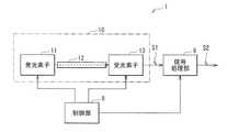
FIG. 1 shows a configuration example of a pulse measuring device (pulse measuring device 1) according to the first embodiment. The pulse measuring device 1 includes a
脈拍計測素子10は、発光素子11と、導光体12と、受光素子13とを有している。発光素子11は、例えばLED(Light Emitting Diode)を用いて構成されるものであり、制御部8による制御に基づいて光を出射するものである。光の波長は、可視領域の波長であってもよいし、近赤外または赤外領域の波長であってもよい。導光体12は、例えばアクリル樹脂を用いて構成されるものであり、発光素子11から出射された光を受光素子13に導くものである。受光素子13は、例えばPD(Photo Diode)を用いて構成されるものであり、導光体12により導かれた光を受光するとともに、その受光量に応じた受光信号S1を信号処理部9に供給するものである。 The
信号処理部9は、受光素子13から供給された受光信号S1に基づいて所定の信号処理を行うことにより、脈拍情報S2を生成するものである。制御部8は、発光素子11、受光素子13、および信号処理部9に制御信号を供給することにより、脈拍計測装置1の動作を制御するものである。 The
この構成により、脈拍計測装置1では、後述するように、人体を導光体12に接触させたときの受光素子13における受光量の変化に基づいて、脈拍情報S2を生成するようになっている。 With this configuration, the pulse measuring device 1 generates pulse information S2 based on a change in the amount of light received by the
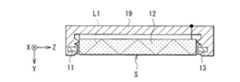
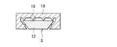
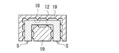
図2は、脈拍計測素子10の一構成例を表すものであり、(A)は、(B)におけるI−I矢視方向の断面図を示し、(B)は、(A)におけるII−II矢視方向の断面図を示す。 FIG. 2 shows a configuration example of the
導光体12は、この例では、XY面内においてアルファベット“T”のような断面形状を有するとともに、Z方向に延伸するものである。発光素子11は、図2(B)に示したように、導光体12の一方の端面12Aと対向する位置に設けられており、受光素子13は、導光体12の他方の端面12Bと対向する位置に設けられている。これにより、発光素子11から出射された光は、導光体12の端面12Aから導光体12の内部に入射し、導光体12の内部を進行して端面12Bに到達し、受光素子13により受光されるようになっている。 In this example, the
発光素子11、導光体12、および受光素子13は、筺体19に収められている。筺体19は、例えば金属やプラスチックなどにより構成することができる。この筺体19は、図2(A)に示したように、XY面内において、導光体12の断面形状と同様の形状を有する空洞を有しており、これにより、導光体12は筺体19に係合するように収められている。脈拍計測素子10では、導光体12の側面(XY面と交差する面)のうち、導光体12の側面Sが露出され、その他の側面は筺体19に覆われている。これにより、人体が導光体12の側面Sに接触することができるようになっている。 The
筺体19の導光体12と対向する面には複数のスペーサ18が形成されている。この例では、複数のスペーサ18は、筺体19と一体形成されている。スペーサ18は、XY面内において三角形の断面形状を有するとともに、Z方向に延伸しており、小さい接触面積で導光体12に接触している。これらのスペーサ18により、筺体19と導光体12との間には、空隙17が形成される。この空隙17における空気の屈折率は、導光体12の屈折率よりも低い。よって、脈拍計測素子10では、発光素子11から出射された光のうちの一部は、導光体12内を進行する際、導光体12の界面で全反射することができるようになっている。 A plurality of
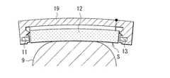
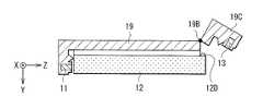
また、この例では、脈拍計測素子10は、図3に示したように、筺体19の一部(開閉部分19C)がヒンジ19Bにより開閉できるようになっている。そして、閉じた場合には、図示しない固定部材により、筺体19の一部(開閉部分19C)が筺体19の本体に固定され、容易に開かないようになっている。このような固定部材は、例えば、一方に設けられた凸部と他方に設けられた凹部が噛み合うはめ込み構造を用いることができる。また、開かないようにネジで固定してもよい。脈拍計測素子10では、筺体19の開閉部分19Cを開き、導光体12をZ方向にスライドさせることにより、導光体12を取り外することができる。これにより、脈拍計測素子10では、例えば導光体12の側面Sが汚れたり、この側面Sに傷が生じたり皮脂がついたりした場合に、導光体12を交換することができる。その結果、脈拍計測装置1では、計測精度を高めることができるようになっている。 Further, in this example, as shown in FIG. 3, the
[動作および作用]
続いて、本実施の形態の脈拍計測装置1の動作および作用について説明する。[Operation and action]
Subsequently, the operation and operation of the pulse measuring device 1 of the present embodiment will be described.
(全体動作概要)
まず、図1を参照して、脈拍計測装置1の全体動作概要を説明する。発光素子11は、制御部8による制御に基づいて光を出射する。導光体12は、発光素子11から出射された光を受光素子13に導く。受光素子13は、導光体12により導かれた光を受光するとともに、その受光量に応じた受光信号S1を信号処理部9に供給する。信号処理部9は、受光素子13から供給された受光信号S1に基づいて所定の信号処理を行うことにより、脈拍情報S2を生成する。制御部8は、脈拍計測装置1の動作を制御する。(Overview of overall operation)
First, with reference to FIG. 1, an outline of the overall operation of the pulse measuring device 1 will be described. The
(詳細動作)
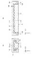
図4A,4Bは、脈拍計測素子10の一動作例を表すものであり、図4Aは、人体が脈拍計測素子10に接触していない場合を示し、図4Bは、人体が脈拍計測素子10に接触している場合を示す。ここで、光L1,L2は、全反射条件を満たす方向に進行する光である。(Detailed operation)
4A and 4B show an operation example of the
発光素子11から出射した光L1は、この例では、界面で全反射しながら導光体12内を進行する。人体が脈拍計測素子10に接触していない場合(図4A)には、光L1は、導光体12の界面で全反射しながら導光体12内を進行し、受光素子13により受光される。 In this example, the light L1 emitted from the
一方、人体が脈拍計測素子10に接触している場合(図4B)には、導光体12内を進行する光は、接触面STを介して人体HBに入射する。すなわち、このように人体HBが導光体12に接触している場合には、その接触面STでは、全反射の条件を満たさなくなるため、光は全反射せず人体HBに入射する。人体HBに入射した光の一部は、人体HBの毛細血管に流れる血液に含まれるヘモグロビンに吸収される。また、人体HBに入射した光の一部は、人体HB内において散乱される。そして、散乱された光の一部は接触面STを介して導光体12に再度入射する。導光体12に再度入射した光の一部(光L2)は、導光体12の界面で全反射しながら導光体12内を進行し、受光素子13により受光される。このように、人体HBに入射した光の一部はヘモグロビンにより吸収されるため、受光素子13における受光量は、毛細血管の容積に応じた量になる。受光素子13は、その受光量に応じた受光信号S1を生成する。そして、信号処理部9は、その受光信号S1に基づいて所定の信号処理を行うことにより、脈拍情報S2を生成する。脈拍計測装置1は、このようにして脈拍を計測する。 On the other hand, when the human body is in contact with the pulse measuring element 10 (FIG. 4B), the light traveling in the
このように、脈拍計測装置1では、導光体12の側面Sを露出するとともに、それ以外の面を覆う筺体19を設けるようにした。そして、脈拍計測装置1では、複数のスペーサ18を設け、筺体19と導光体12との間に空隙17を形成した。これにより、発光素子11から出射した光L1が導光体12内を進行する際、側面S以外の側面において光を全反射させることができるとともに、側面Sにおける接触面ST以外の領域においても光を全反射させることができる。これにより、脈拍計測装置1では、発光素子11から出射された光や、人体HB内において散乱され導光体12に再度入射した光を効果的に受光素子13に導くことができるので、計測精度を高めることができる。 As described above, in the pulse measuring device 1, the side surface S of the
また、脈拍計測装置1では、導光体12を、筺体19に係合するように構成した。具体的には、導光体12を、XY面内においてアルファベット“T”のような断面形状を有するように構成するとともに、筺体19を、同じアルファベット“T”のような形状の空洞を有するように構成した。これにより、シンプルな構成で、導光体12を筺体19内に固定し、外れにくくすることができる。 Further, in the pulse measuring device 1, the
また、脈拍計測装置1では、導光体12を交換可能に構成したので、例えば導光体12の側面Sが汚れたり、この側面Sに傷が生じたり皮脂がついたりした場合に、導光体12を交換することができる。その結果、脈拍計測装置1では、計測精度を高めることができるようになっている。 Further, in the pulse measuring device 1, since the
[効果]
以上のように本実施の形態では、導光体の側面Sを露出するとともに、それ以外の面を覆う筺体を設けるとともに、複数のスペーサを設け、筺体と導光体との間に空隙を形成したので、計測精度を高めることができる。[effect]
As described above, in the present embodiment, the side surface S of the light guide body is exposed, a housing body covering the other surfaces is provided, and a plurality of spacers are provided to form a gap between the housing body and the light guide body. Therefore, the measurement accuracy can be improved.
本実施の形態では、導光体を、筺体に係合するように構成したので、シンプルな構成で、導光体を筺体内に固定し、外れにくくすることができる。 In the present embodiment, since the light guide body is configured to engage with the housing body, the light guide body can be fixed in the housing body and hard to come off with a simple structure.
本実施の形態では、導光体を交換可能に構成したので、計測精度を高めることができる。 In the present embodiment, since the light guide body is configured to be replaceable, the measurement accuracy can be improved.
[変形例1−1]
上記実施の形態において、導光体12および筺体19を、弾性樹脂を用いて構成してもよい。これにより、図5に示したように、脈拍計測素子10を、人体の接触させる部位に合わせて湾曲させることができ、接触面積を広くすることができる。その結果、人体の腕、足、首などの様々な部位に接触させて脈拍測定を行うことができる。このような導光体12は、例えばシリコン樹脂やアートン樹脂などを用いて構成することができる。また、このような筺体19は、例えばウレタン樹脂や軟性エポキシ樹脂などを用いて構成することができる。[Modification 1-1]
In the above embodiment, the
[変形例1−2]
上記実施の形態では、ヒンジ19Bを設け、筺体19の一部(開閉部分19C)が開閉できるようにしたが、これに限定されるものではない。例えば、ヒンジ19Bを設けず、筺体19の本体と一部(開閉部分19C)とを分離可能に構成してもよい。また、例えば、図6に示したように、筺体19の本体と、一部(開閉部分19C)とを、軟質材料により構成された接続部材19Dを用いて接続するようにしてもよい。この例では、筺体19には、接続部材19Dを収容するための穴が設けられている。そして、筺体19の本体と一部(開閉部分19C)とを結合した場合には、この接続部材19Dは、筺体19に設けられた穴に収容される。[Modification 1-2]
In the above embodiment, the
[変形例1−3]
上記実施の形態では、スペーサ18を、XY面内において三角形の断面形状を有するとともに、Z方向に延伸するように構成したが、これに限定されるものではない。例えば、図7に示したように、円錐のような形状を有するスペーサ18を用いてもよい。この例では、Z方向において、スペーサ18をランダムに配置している。なお、これに限定されるものではなく、Z方向において、スペーサ18を等間隔で配置してもよい。また、例えば、図8に示したように、半球のような形状を有するスペーサ18を用いてもよい。[Modification 1-3]
In the above embodiment, the
[変形例1−4]
上記実施の形態では、導光体12が、XY面内においてアルファベット“T”のような断面形状を有するようにしたが、これに限定されるものではない。例えば、図9Aに示すように、導光体12が、台形の断面形状を有するようにしてもよい。この台形の下辺は、側面Sに対応しており、下辺の長さは上辺の長さよりも短くなっている。筺体19は、導光体12の断面形状と同様の形状を有する空洞を有しており、導光体12は筺体19に係合するように収められている。この構成でも、導光体12を筺体19内に固定することができ、導光体12を外れにくくすることができる。[Modification 1-4]
In the above embodiment, the
同様に、例えば、図9Bに示すように、導光体12が、XY面内において円の一部を切り落としたような断面形状を有するようにしてもよい。この円の切り落とした部分が側面Sに対応している。また、例えば、図9Cに示すように、導光体12が、複数の長方形を結合した形状の断面形状を有するようにしてもよい。この形状の下辺は、側面Sに対応しており、下辺の長さは上辺の長さよりも短くなっている。また、例えば、図9Dに示すように、導光体12が、六角形の断面形状を有するようにしてもよい。この六角形の一辺が側面Sに対応している。また、例えば、図9Eに示すように、導光体12が、十字形の断面形状を有するようにしてもよい。この十字形の一部が側面Sに対応している。 Similarly, for example, as shown in FIG. 9B, the
また、例えば、図9Fに示すように、導光体12が、アルファベット“U”の角を尖らせたような断面形状を有するようにしてもよい。この“U”の字の内側に筺体19の一部が配置されることにより、導光体12が筺体19に係合する。この例では、“U”の字の両端の2つの部分が側面Sに対応している。また、例えば、図9Gに示すように、導光体12が、半円弧のような断面形状を有するようにしてもよい。この半円弧の内側に筺体19の一部が配置されることにより、導光体12が筺体19に係合する。この例では、半円弧の両端の2つの部分が側面Sに対応している。また、例えば、図9Hに示すように、導光体12が、中央部に中空領域がある四角形のような断面形状を有するようにしてもよい。この中空領域に筺体19の一部が配置されることにより、導光体12が筺体19に係合する。この例では、四角形の下辺が側面Sに対応している。 Further, for example, as shown in FIG. 9F, the
[その他の変形例]
また、これらの変形例のうちの2以上を組み合わせてもよい。[Other variants]
Moreover, you may combine two or more of these modified examples.
<2.第2の実施の形態>
次に、第2の実施の形態に係る脈拍計測装置2について説明する。本実施の形態は、空隙17を設ける方法が、上記第1の実施の形態と異なるものである。すなわち、上記第1の実施の形態(図2)では、スペーサ18を用いて空隙17を設けるようにしたが、これに代えて、本実施の形態では、スペーサ18を用いることなく空隙を設けるようにしている。なお、上記第1の実施の形態に係る脈拍計測装置1と実質的に同一の構成部分には同一の符号を付し、適宜説明を省略する。<2. Second Embodiment>
Next, the
図10は、脈拍計測装置2の脈拍計測素子20の一構成例を表すものであり、(A)は、(B)におけるIII−III矢視方向の断面図を示し、(B)は、(A)におけるIV−IV矢視方向の断面図を示す。脈拍計測素子20は、発光素子11と、導光体22と、受光素子13とを有している。発光素子11、導光体22、および受光素子13は、筺体29に収められている。 10A and 10B show a configuration example of the
導光体22は、本体部22Aと、支持部22B,22Cとを有している。本体部22Aは、XY面において四角形の断面形状を有しており、支持部22B,22Cは台形の断面形状を有している。支持部22B,22Cは、図10(A)に示したように、本体部22Aの左右にそれぞれ配置されている。支持部22B,22Cは、筺体29の内面と接触している。このように、脈拍計測素子20では、支持部22B,22Cが筺体29の内面に接触することにより、導光体22が支持され、その結果、本体部22Aと筺体29との間に空隙27が生じるようになっている。 The
このように、脈拍計測装置2では、筺体29の内面と接することにより導光体22を支持する支持部22B,22Cを設けるようにした。特に、脈拍計測装置2では、上記第1の実施の形態に係る導光体12と異なり、本体部22Aにスペーサがないため、全反射により光を効果的に受光素子13に導くことができるので、計測精度を高めることができる。 As described above, in the
以上のように本実施の形態では、筺体の内面と接することにより導光体を支持する支持部を設けるようにしたので、計測精度を高めることができる。 As described above, in the present embodiment, since the support portion for supporting the light guide body is provided by being in contact with the inner surface of the housing body, the measurement accuracy can be improved.
[変形例2−1]
上記実施の形態では、支持部22B,22Cが、XY面において台形の断面形状を有するものとしたが、これに限定されるものではない。これに代えて、図11Aに示すように、円形のうちの一部を切り落としたような断面形状を有するようにしてもよい。この例では、支持部22B,22Cに中空領域を設け、その中空領域に筺体29の一部が配置されるようにしている。また、図11Bに示すように、四角形の断面形状を有するようにしてもよい。この例でも、支持部22B,22Cに中空領域を設け、その中空領域に筺体29の一部が配置されるようにしている。なお、これに限定されるものではなく、支持部22B,22Cに中空領域を設けなくてもよい。また、これらの例では、本体部22Aの左右に2つの支持部22B,22Cを設けたが、これに限定されるものではなく、これに代えて、例えば、図11Cに示すように、1つの支持部22Dを設けてもよい。この例では、本体部22Aの上側に支持部22Dを設けたが、これに限定されるものではなく、これに代えて、本体部22Aの左側に支持部22Dを設けてもよいし、本体部22Aの右側に支持部22Dを設けてもよい。[Modification 2-1]
In the above embodiment, the
<3.第3の実施の形態>
次に、第3の実施の形態に係る脈拍計測装置3について説明する。本実施の形態は、導光体と筺体との間に、導光体よりも屈折率が低い光学部材を配置したものである。なお、上記第1の実施の形態に係る脈拍計測装置1と実質的に同一の構成部分には同一の符号を付し、適宜説明を省略する。<3. Third Embodiment>
Next, the pulse measuring device 3 according to the third embodiment will be described. In the present embodiment, an optical member having a refractive index lower than that of the light guide is arranged between the light guide and the housing. The same components as those of the pulse measuring device 1 according to the first embodiment are designated by the same reference numerals, and the description thereof will be omitted as appropriate.
図12は、脈拍計測装置3の脈拍計測素子30の一構成例を表すものであり、(A)は、(B)におけるV−V矢視方向の断面図を示し、(B)は、(A)におけるVI−VI矢視方向の断面図を示す。脈拍計測素子30は、発光素子11と、導光体32と、受光素子13とを有している。発光素子11、導光体32、および受光素子13は、筺体39に収められている。 FIG. 12 shows a configuration example of the pulse measuring element 30 of the pulse measuring device 3, where (A) shows a cross-sectional view in the direction of the arrow VV in (B), and (B) is (B). A cross-sectional view in the direction of the arrow VI-VI in A) is shown. The pulse measuring element 30 includes a
導光体32と筺体39の内面との間には、光学部材37が設けられている。この光学部材37は、その屈折率が導光体32の屈折率よりも低いものである。例えば、屈折率が1.49のアクリル樹脂を用いて導光体32を構成した場合には、屈折率が1.34のフッ素樹脂を用いて光学部材37を構成することができる。これにより、発光素子11から出射した光が導光体32内を進行する際、導光体32の界面において光を全反射させることができる。 An
このように、脈拍計測装置3では、導光体32と筺体39の内面との間に、導光体32の屈折率よりも低い屈折率を有する光学部材37を設けるようにした。特に、脈拍計測装置3では、上記第1の実施の形態に係る導光体12と異なり、スペーサがないため、全反射により光を効果的に受光素子13に導くことができるので、計測精度を高めることができる。 As described above, in the pulse measuring device 3, the
以上のように本実施の形態では、導光体と筺体の内面との間に、導光体の屈折率よりも低い屈折率を有する光学部材を設けるようにしたので、計測精度を高めることができる。 As described above, in the present embodiment, an optical member having a refractive index lower than that of the light guide is provided between the light guide and the inner surface of the housing, so that the measurement accuracy can be improved. it can.
<4.適用例>
次に、上記実施の形態および変形例で説明した脈拍計測装置の適用例について説明する。<4. Application example>
Next, an application example of the pulse measuring device described in the above-described embodiment and modified example will be described.
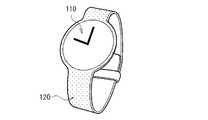
図13は、上記実施の形態等の脈拍計測装置が適用される腕時計の外観を表すものである。この腕時計は、例えば、文字盤110と、バンド部120とを有している。この文字盤110の裏側の、ユーザの腕と接触する面には、上記実施の形態等に係る脈拍計測装置が搭載されている。 FIG. 13 shows the appearance of a wristwatch to which the pulse measuring device of the above embodiment is applied. This wristwatch has, for example, a
上記実施の形態等の脈拍計測装置は、このような腕時計の他、リストバンド、眼鏡、指輪など、ユーザが身につける様々なものに適用することが可能であり、これにより、脈拍を計測可能なウェアラブル端末を構成することができる。 The pulse measuring device according to the above embodiment can be applied to various things worn by the user, such as a wristband, eyeglasses, and a ring, in addition to such a wristwatch, whereby the pulse can be measured. Wearable terminal can be configured.
以上、いくつかの実施の形態および変形例、ならびにそれらの具体的な応用例および電子機器への適用例を挙げて本技術を説明したが、本技術はこれらの実施の形態等には限定されず、種々の変形が可能である。 Although the present technology has been described above with reference to some embodiments and modifications, specific application examples thereof, and application examples to electronic devices, the present technology is limited to these embodiments and the like. However, various modifications are possible.
例えば、上記の各実施の形態では、導光体を交換可能に構成したが、その際、図14に示すように、導光体12に突起部12Dを設けることにより、筺体19から導光体12を引き出しやすくしてもよい。なお、この例では、第1の実施の形態に係る脈拍計測素子10に本変形例を適用したが、第2の実施の形態に係る脈拍計測素子20および第3の実施の形態に係る脈拍計測素子30にも適用することができる。 For example, in each of the above-described embodiments, the light guide body is configured to be replaceable. At that time, as shown in FIG. 14, the
なお、本明細書に記載された効果はあくまで例示であって限定されるものでは無く、また他の効果があってもよい。 The effects described in the present specification are merely examples and are not limited, and other effects may be obtained.
当業者であれば、設計上の要件や他の要因に応じて、種々の修正、コンビネーション、サブコンビネーション、および変更を想到し得るが、それらは添付の請求の範囲やその均等物の範囲に含まれるものであることが理解される。 One of ordinary skill in the art can conceive of various modifications, combinations, sub-combinations, and changes, depending on design requirements and other factors, but they are included in the appended claims and their equivalents. It is understood that it is something to be done.
Claims (12)
Translated fromJapanese発光素子と、
受光素子と、
前記発光素子と対向する第1の端面と、前記第1の端面と対向するとともに前記受光素子と対向する第2の端面と、前記筺体に覆われた1または複数の第1の側面と、前記筺体から露出された1または複数の第2の側面とを有する導光体と
を備え、
前記導光体は、前記筐体と係合し、前記筐体から取り外し可能である
脈拍計測素子。With the housing
Light emitting element and
With the light receiving element
A first end face facing the light emitting element, a second end face facing the first end face and facing the light receiving element, one or more first side surfaces covered with the housing, and the said. With a light guide having one or more second sides exposed from the housing,
The light guide body is a pulse measuring element that engages with the housing and is removable from the housing.
請求項1に記載の脈拍計測素子。The pulse measuring element according to claim 1, wherein the housing is configured so that the light guide body can be slidable in a predetermined direction in the plane of the one or a plurality of second side surfaces.
請求項1または請求項2に記載の脈拍計測素子。The pulse measuring element according to claim 1 or 2, wherein the shape of the inner surface of the housing facing the one or more first side surfaces corresponds to the shape of the one or more first side surfaces.
請求項1から請求項3のいずれか一項に記載の脈拍計測素子。The pulse measuring element according to any one of claims 1 to 3, wherein the one or more first side surfaces include a third side surface separated from the inner surface of the housing.
請求項4に記載の脈拍計測素子。The pulse measuring element according to claim 4, wherein a gap is provided between the third side surface and the inner surface of the housing.
請求項5に記載の脈拍計測素子。The pulse measuring element according to claim 5, further comprising one or more spacers provided between the third side surface and the inner surface of the housing.
請求項5に記載の脈拍計測素子。The pulse measuring element according to claim 5, wherein the one or more first side surfaces include a fourth side surface in contact with the inner surface of the housing.
請求項4に記載の脈拍計測素子。The pulse measuring element according to claim 4, further comprising an optical member provided between the third side surface and the inner surface of the housing and having a refractive index smaller than that of the light guide body.
請求項1から請求項8のいずれか一項に記載の脈拍計測素子。The pulse measuring element according to any one of claims 1 to 8, wherein the light guide body and the housing body are made of an elastic resin.
請求項1から請求項9のいずれか一項に記載の脈拍計測素子。The pulse measuring element according to any one of claims 1 to 9, wherein the light emitting element and the light receiving element are fixed in the housing.
前記受光素子における受光量に基づいてユーザの脈拍情報を生成する信号処理部と
を備え、
前記導光体は、前記筐体と係合し、前記筐体から取り外し可能である
脈拍計測装置。The housing, the light emitting element, the light receiving element, the first end face facing the light emitting element, the second end face facing the first end face and facing the light receiving element, and the housing covered with the housing. A pulse measuring device including a light guide body having one or more first side surfaces and one or more second side surfaces exposed from the housing.
It is provided with a signal processing unit that generates pulse information of the user based on the amount of light received by the light receiving element.
The light guide body is a pulse measuring device that engages with the housing and is removable from the housing.
前記受光素子における受光量に基づいてユーザの脈拍情報を生成する信号処理部と
前記脈拍情報を用いて所定の処理を行う処理部と
を備え、
前記導光体は、前記筐体と係合し、前記筐体から取り外し可能である
電子機器。
The housing, the light emitting element, the light receiving element, the first end face facing the light emitting element, the second end face facing the first end face and facing the light receiving element, and the housing covered with the housing. A pulse measuring device including a light guide body having one or more first side surfaces and one or more second side surfaces exposed from the housing.
It is provided with a signal processing unit that generates user's pulse information based on the amount of light received by the light receiving element and a processing unit that performs predetermined processing using the pulse information.
The light guide body is an electronic device that engages with the housing and is removable from the housing.
Applications Claiming Priority (2)
| Application Number | Priority Date | Filing Date | Title |
|---|---|---|---|
| JP2015238185 | 2015-12-07 | ||
| JP2015238185 | 2015-12-07 |
Related Parent Applications (1)
| Application Number | Title | Priority Date | Filing Date |
|---|---|---|---|
| JP2017554990ADivisionJP6763399B2 (en) | 2015-12-07 | 2016-11-16 | Pulse measuring element, pulse measuring device, and electronic device |
Publications (2)
| Publication Number | Publication Date |
|---|---|
| JP2020192394Atrue JP2020192394A (en) | 2020-12-03 |
| JP6992861B2 JP6992861B2 (en) | 2022-01-13 |
Family
ID=59014013
Family Applications (2)
| Application Number | Title | Priority Date | Filing Date |
|---|---|---|---|
| JP2017554990AExpired - Fee RelatedJP6763399B2 (en) | 2015-12-07 | 2016-11-16 | Pulse measuring element, pulse measuring device, and electronic device |
| JP2020144999AExpired - Fee RelatedJP6992861B2 (en) | 2015-12-07 | 2020-08-28 | Pulse measuring element, pulse measuring device, and electronic device |
Family Applications Before (1)
| Application Number | Title | Priority Date | Filing Date |
|---|---|---|---|
| JP2017554990AExpired - Fee RelatedJP6763399B2 (en) | 2015-12-07 | 2016-11-16 | Pulse measuring element, pulse measuring device, and electronic device |
Country Status (3)
| Country | Link |
|---|---|
| US (1) | US10912468B2 (en) |
| JP (2) | JP6763399B2 (en) |
| WO (1) | WO2017098872A1 (en) |
Families Citing this family (2)
| Publication number | Priority date | Publication date | Assignee | Title |
|---|---|---|---|---|
| DE102015122768A1 (en)* | 2015-12-23 | 2017-06-29 | Temicon Gmbh | Plate-shaped optical element for coupling out light |
| EP3895607A4 (en) | 2018-12-14 | 2022-09-28 | Sony Group Corporation | DEVICE FOR MEASURING BIOLOGICAL SIGNALS |
Citations (7)
| Publication number | Priority date | Publication date | Assignee | Title |
|---|---|---|---|---|
| JP2001256487A (en)* | 2000-03-10 | 2001-09-21 | Omron Corp | Fingerprint collating unit |
| WO2003021239A1 (en)* | 2001-08-28 | 2003-03-13 | Matsushita Electric Industrial Co., Ltd. | Apparatus for measuring information on particular component |
| JP2006081893A (en)* | 2004-08-20 | 2006-03-30 | Matsushita Electric Ind Co Ltd | Biological information measuring optical member, biological information calculating apparatus, biological information calculating method, program, and recording medium |
| JP2008099890A (en)* | 2006-10-19 | 2008-05-01 | Sharp Corp | Biological information measuring device |
| JP2010029496A (en)* | 2008-07-30 | 2010-02-12 | Ricoh Co Ltd | Biological light measuring instrument and probe for the same |
| JP2012176225A (en)* | 2010-09-21 | 2012-09-13 | Nippon Telegr & Teleph Corp <Ntt> | Biological information detector |
| US8320985B2 (en)* | 2009-04-02 | 2012-11-27 | Empire Technology Development Llc | Touch screen interfaces with pulse oximetry |
Family Cites Families (8)
| Publication number | Priority date | Publication date | Assignee | Title |
|---|---|---|---|---|
| JPH07184883A (en) | 1993-12-27 | 1995-07-25 | Satoshi Yoshida | Biological surface measuring device |
| US5913819A (en)* | 1996-04-26 | 1999-06-22 | Datex-Ohmeda, Inc. | Injection molded, heat-sealed housing and half-etched lead frame for oximeter sensor |
| JP4258094B2 (en)* | 2000-04-14 | 2009-04-30 | 株式会社デンソー | Biological signal detection device |
| US7236814B2 (en) | 2004-08-20 | 2007-06-26 | Matsushita Electric Industrial Co., Ltd. | Optical member for biological information measurement, biological information calculation apparatus, biological information calculation method, computer-executable program, and recording medium |
| EP3127476A1 (en) | 2009-02-25 | 2017-02-08 | Valencell, Inc. | Light-guiding devices and monitoring devices incorporating same |
| US20110291995A1 (en)* | 2010-05-25 | 2011-12-01 | Industrial Technology Research Institute | Sterilizing device and manufacturing method for sterilizing device |
| JP2015093163A (en) | 2013-11-14 | 2015-05-18 | 株式会社豊田中央研究所 | Pulse measuring device |
| US20170079591A1 (en)* | 2015-09-21 | 2017-03-23 | Qualcomm Incorporated | System and method for obtaining vital measurements using a mobile device |
- 2016
- 2016-11-16USUS15/777,870patent/US10912468B2/ennot_activeExpired - Fee Related
- 2016-11-16JPJP2017554990Apatent/JP6763399B2/ennot_activeExpired - Fee Related
- 2016-11-16WOPCT/JP2016/083913patent/WO2017098872A1/ennot_activeCeased
- 2020
- 2020-08-28JPJP2020144999Apatent/JP6992861B2/ennot_activeExpired - Fee Related
Patent Citations (7)
| Publication number | Priority date | Publication date | Assignee | Title |
|---|---|---|---|---|
| JP2001256487A (en)* | 2000-03-10 | 2001-09-21 | Omron Corp | Fingerprint collating unit |
| WO2003021239A1 (en)* | 2001-08-28 | 2003-03-13 | Matsushita Electric Industrial Co., Ltd. | Apparatus for measuring information on particular component |
| JP2006081893A (en)* | 2004-08-20 | 2006-03-30 | Matsushita Electric Ind Co Ltd | Biological information measuring optical member, biological information calculating apparatus, biological information calculating method, program, and recording medium |
| JP2008099890A (en)* | 2006-10-19 | 2008-05-01 | Sharp Corp | Biological information measuring device |
| JP2010029496A (en)* | 2008-07-30 | 2010-02-12 | Ricoh Co Ltd | Biological light measuring instrument and probe for the same |
| US8320985B2 (en)* | 2009-04-02 | 2012-11-27 | Empire Technology Development Llc | Touch screen interfaces with pulse oximetry |
| JP2012176225A (en)* | 2010-09-21 | 2012-09-13 | Nippon Telegr & Teleph Corp <Ntt> | Biological information detector |
Also Published As
| Publication number | Publication date |
|---|---|
| JP6763399B2 (en) | 2020-09-30 |
| JPWO2017098872A1 (en) | 2018-09-20 |
| US20180368709A1 (en) | 2018-12-27 |
| US10912468B2 (en) | 2021-02-09 |
| WO2017098872A1 (en) | 2017-06-15 |
| JP6992861B2 (en) | 2022-01-13 |
Similar Documents
| Publication | Publication Date | Title |
|---|---|---|
| US11252499B2 (en) | Optical physiological monitoring devices | |
| CN107438400B (en) | Lightguide Systems for Physiological Sensors | |
| JP6992861B2 (en) | Pulse measuring element, pulse measuring device, and electronic device | |
| US11197636B2 (en) | Stabilized sensor modules and monitoring devices incorporating same | |
| EP2781186A1 (en) | Biological information detection apparatus | |
| JP2015073824A (en) | Biological information measuring device | |
| US20210168539A1 (en) | Hearing aid device with biometric sensor | |
| US20210038161A1 (en) | Ear gel modules and earpiece monitoring devices incorporating same | |
| JP2018029778A (en) | Brain function measurement device | |
| US10357188B2 (en) | Flexible optical source for pulse oximetry | |
| US20160040868A1 (en) | Illuminated hair band | |
| JP1707054S (en) | Lens for eyeglasses | |
| KR102064664B1 (en) | Low-noise wearable device for monitoring biometric information | |
| FI131618B1 (en) | NOSE PAD SETUP FOR MEASURING PULSE AND OPTICAL DEVICE AND METHOD USING SAID SETUP | |
| CN108732788A (en) | A kind of healthy magnetic therapeutic spectacles frame | |
| TWI690300B (en) | Wearable eyebrow emitting apparatus | |
| CN104519785B (en) | Glasses with high flexibility when in use | |
| CN104519785A (en) | Glasses with high flexibility when in use | |
| CH704734A8 (en) | Utility and / or ornamental device having at least a portion of a golf ball. |
Legal Events
| Date | Code | Title | Description |
|---|---|---|---|
| A621 | Written request for application examination | Free format text:JAPANESE INTERMEDIATE CODE: A621 Effective date:20200828 | |
| A977 | Report on retrieval | Free format text:JAPANESE INTERMEDIATE CODE: A971007 Effective date:20210430 | |
| A131 | Notification of reasons for refusal | Free format text:JAPANESE INTERMEDIATE CODE: A131 Effective date:20210601 | |
| A521 | Request for written amendment filed | Free format text:JAPANESE INTERMEDIATE CODE: A523 Effective date:20210707 | |
| TRDD | Decision of grant or rejection written | ||
| A01 | Written decision to grant a patent or to grant a registration (utility model) | Free format text:JAPANESE INTERMEDIATE CODE: A01 Effective date:20211109 | |
| A61 | First payment of annual fees (during grant procedure) | Free format text:JAPANESE INTERMEDIATE CODE: A61 Effective date:20211122 | |
| R151 | Written notification of patent or utility model registration | Ref document number:6992861 Country of ref document:JP Free format text:JAPANESE INTERMEDIATE CODE: R151 | |
| LAPS | Cancellation because of no payment of annual fees |