JP2020187413A - Plant data monitoring system and plant data monitoring method - Google Patents
Plant data monitoring system and plant data monitoring methodDownload PDFInfo
- Publication number
- JP2020187413A JP2020187413AJP2019089861AJP2019089861AJP2020187413AJP 2020187413 AJP2020187413 AJP 2020187413AJP 2019089861 AJP2019089861 AJP 2019089861AJP 2019089861 AJP2019089861 AJP 2019089861AJP 2020187413 AJP2020187413 AJP 2020187413A
- Authority
- JP
- Japan
- Prior art keywords
- plant data
- gateway device
- plant
- data
- gateway
- Prior art date
- Legal status (The legal status is an assumption and is not a legal conclusion. Google has not performed a legal analysis and makes no representation as to the accuracy of the status listed.)
- Pending
Links
Images


Landscapes
- Testing And Monitoring For Control Systems (AREA)
- Data Exchanges In Wide-Area Networks (AREA)
Abstract
Translated fromJapaneseDescription
Translated fromJapanese本発明の実施形態は、プラントデータ監視システムおよびプラントデータ監視方法に関する。 Embodiments of the present invention relate to a plant data monitoring system and a plant data monitoring method.
例えば火力発電所などの発電プラントでは、発電プラント内で稼働する機器(ポンプやタービンなど)のデータ(プラントデータ)を取得する複数のセンサ機器とネットワークおよび複数のゲートウェイ装置を介して接続される監視サーバとを備えるプラントデータ監視システムが用いられている。 For example, in a power plant such as a thermal power plant, monitoring is connected via a network and multiple gateway devices to multiple sensor devices that acquire data (plant data) of equipment (pumps, turbines, etc.) operating in the power plant. A plant data monitoring system equipped with a server is used.
通常、このようなプラントデータ監視システムでは、各センサ機器からのプラントデータを中継するゲートウェイ装置を割り当て、そのゲートウェイ装置を介して監視サーバがプラントデータを受信することで、各機器の動作状態を監視しており、監視サーバが監視した情報を監視用の端末やモニタパネルに表示し運転員に提供することで、発電プラントの運転支援を行っている。 Normally, in such a plant data monitoring system, a gateway device that relays plant data from each sensor device is assigned, and the monitoring server receives the plant data via the gateway device to monitor the operating status of each device. By displaying the information monitored by the monitoring server on the monitoring terminal or monitor panel and providing it to the operators, the operation support of the power plant is provided.
ここで、従来のプラントデータ監視システムの動作を説明する。
従来のプラント監視システムの場合、システムを起動したときに、複数のゲートウェイ装置それぞれが監視サーバに対してプラントデータ毎のゲートウェイ装置割り当て番号や、それらプラントデータの名称や更新周期などを含むプラントデータ属性情報を要求する。Here, the operation of the conventional plant data monitoring system will be described.
In the case of a conventional plant monitoring system, when the system is started, each of the multiple gateway devices has a plant data attribute that includes the gateway device allocation number for each plant data, the name of the plant data, the update cycle, etc. for the monitoring server. Request information.
監視サーバは、プラントデータ属性情報の要求を受けて、予めプラントデータ属性情報が登録されているプラントデータ管理テーブルを参照して、要求元のゲートウェイ装置に担当するプラントデータのIDを割り当てて、IDに対応するプラントデータ属性情報(プラントデータ名称、周期(ms)、通信先装置、通信プロトコルなど)を要求元のゲートウェイ装置に返す。 Upon receiving the request for plant data attribute information, the monitoring server refers to the plant data management table in which the plant data attribute information is registered in advance, assigns the ID of the plant data in charge to the requesting gateway device, and assigns the ID. The plant data attribute information (plant data name, period (ms), communication destination device, communication protocol, etc.) corresponding to is returned to the request source gateway device.
ゲートウェイ装置は、取得したプラントデータ属性情報に従い該当する通信対象のデータ取得装置に対してプラントデータの取得要求を行う。 The gateway device requests the data acquisition device of the corresponding communication target to acquire the plant data according to the acquired plant data attribute information.
取得要求を受けたデータ取得装置は、要求元のゲートウェイ装置に対して当該プラントデータを指定された周期、通信プロトコルにて返す。 The data acquisition device that received the acquisition request returns the plant data to the request source gateway device in the specified cycle and communication protocol.
ゲートウェイ装置は、データ取得装置から取得したプラントデータを、監視サーバに送信する。監視サーバでは、受信したプラントデータを構成管理用データベースに格納する。 The gateway device transmits the plant data acquired from the data acquisition device to the monitoring server. The monitoring server stores the received plant data in the configuration management database.
このようなプラントデータ監視システムでは、すべてのセンサ機器のプラントデータを中断することなく監視し続けられるような継続稼働による信頼性が求められる。 In such a plant data monitoring system, reliability by continuous operation is required so that the plant data of all sensor devices can be continuously monitored without interruption.
しかしながら、従来のプラントデータ監視システムの場合、監視サーバは、ゲートウェイ装置起動時にプラントデータのIDを割り当てた後、ゲートウェイ装置に対してIDの割り当て変更を行わないため、プラント運転中にゲートウェイ装置が故障したり過負荷になるなどしてデータの中継動作が停止した場合、復旧するまでの間、そのゲートウェイ装置を中継するプラントデータが長期的に欠損することになり、プラントデータの監視に支障をきたすという問題があった。 However, in the case of the conventional plant data monitoring system, the monitoring server assigns the ID of the plant data when the gateway device is started, and then does not change the ID assignment to the gateway device. Therefore, the gateway device fails during plant operation. If the data relay operation is stopped due to overload or overload, the plant data relaying the gateway device will be lost for a long period of time until it is restored, which will hinder the monitoring of the plant data. There was a problem.
本発明が解決しようとする課題は、複数のゲートウェイ装置の中の1つが過負荷に陥るまたは停止したときに、プラントデータの欠損を最低限にとどめて監視を継続することができるプラントデータ監視システムおよびプラントデータ監視方法を提供することにある。 The problem to be solved by the present invention is a plant data monitoring system capable of continuing monitoring while minimizing the loss of plant data when one of a plurality of gateway devices is overloaded or stopped. And to provide a method for monitoring plant data.
実施形態のプラントデータ監視システムは、監視用のコンピュータと、複数のゲートウェイ装置と、プラントで稼働するデータ発生源の機器に設けられる複数のデータ取得装置とをネットワークを介して接続したプラントデータ監視システムであり、監視用のコンピュータが、記憶部、監視部、割当部を有する。記憶部には、前記データ取得装置が前記データ発生源の機器から取得するプラントデータの識別情報に、該プラントデータの中継担当として割り当てられているゲートウェイ装置の識別情報と、前記データ発生源の機器の種別毎に付与された静的優先度と、前記データ発生源の機器の運転モードに応じた重要度と、前記重要度と前記静的優先度とから求められる動的優先度とが対応付けて記憶されている。監視部はデータ発生源の機器および複数のゲートウェイ装置の動作状況を予め設定された更新周期毎に監視し、データ発生源の機器の現在の運転モードと、停止中またはCPU負荷率が一定値以上の高負荷のゲートウェイ装置を検出する。割当部は、記憶部を参照して、停止中または高負荷として検出されたゲートウェイ装置に割り当てられているプラントデータの識別情報と検出時の運転モードに応じた動的優先度を基に、停止中または高負荷のゲートウェイ装置が担当しているプラントデータの識別情報を、現在稼働中の他のゲートウェイ装置に割り当てる。 The plant data monitoring system of the embodiment is a plant data monitoring system in which a computer for monitoring, a plurality of gateway devices, and a plurality of data acquisition devices provided in a data source device operating in the plant are connected via a network. The monitoring computer has a storage unit, a monitoring unit, and an allocation unit. In the storage unit, the identification information of the gateway device assigned as the relay charge of the plant data to the identification information of the plant data acquired by the data acquisition device from the device of the data source, and the device of the data source. The static priority assigned to each type of data, the importance according to the operation mode of the device of the data source, and the dynamic priority obtained from the importance and the static priority are associated with each other. Is remembered. The monitoring unit monitors the operating status of the data source device and multiple gateway devices at preset update cycles, and the current operation mode of the data source device and the stopped state or CPU load factor is above a certain value. Detects high-load gateway devices. The allocation unit refers to the storage unit and stops based on the identification information of the plant data assigned to the gateway device detected as stopped or high load and the dynamic priority according to the operation mode at the time of detection. Allocate the identification information of the plant data that the medium or high load gateway device is in charge of to other gateway devices that are currently in operation.
以下、図面を参照して、実施形態を詳細に説明する。
図1は一つの実施形態のプラントデータ監視システムを示す図である。Hereinafter, embodiments will be described in detail with reference to the drawings.
FIG. 1 is a diagram showing a plant data monitoring system of one embodiment.
図1に示すように、この実施形態のプラントデータ監視システムは、監視用のコンピュータ1(以下これを「サーバ1」と称す)とネットワーク4を介して接続されるゲートウェイ装置#1〜#nと、これらゲートウェイ装置#1〜#nとネットワーク9を介して接続される監視対象の複数のデータ取得装置としての通信先装置10〜13と、各通信先装置10〜13が設けられたデータ発生源の機器15〜18(以下これを「プラント機器15〜18」と称す)とを備える。ネットワーク4は監視ネットワークである。ネットワーク9は情報ネットワークである。互いのネットワーク間は異なるプロトコルが用いられるため、プロトコル変換のためのゲートウェイ装置#1〜#nが必要である。 As shown in FIG. 1, the plant data monitoring system of this embodiment includes a monitoring computer 1 (hereinafter referred to as “
すなわち、このプラントデータ監視システムは、サーバ1と、複数のゲートウェイ装置#1〜#nと、プラントで稼働するプラント機器15〜18に設けられる複数の通信先装置10〜13とをネットワーク4、9を介して接続したものである。 That is, this plant data monitoring system connects the
サーバ1は、構成管理用のデータベース2および通信監視部3を備えている。通信監視部3は各ゲートウェイ装置#1〜#nに監視対象の通信先装置10〜13を割り当てて、通信先装置10〜13からゲートウェイ装置#1〜#nを通じてプラントデータを収集し、収集したプラントをデータベース2に保存および管理する。 The
ゲートウェイ装置#1〜#nは、サーバ1により割り当てられたプラントデータIDの通信先装置10〜13と予め定められたプロトコルによって通信し、当該通信先装置10〜13により取得されるプラントデータをサーバ1へ転送する。 The
通信先装置10〜13は、例えば流量計などの計測器、圧力センサなどの検出器や検出器からの信号を使用する制御装置および監視装置であり、検出されるデータにプラントデータIDが付与される。ここで、制御装置とは、例えば検出器からの信号を使用し、タービン起動や停止などの制御を行うPLC(プログラマブルコントローラ)のようなものを言う。監視装置とは、各プラント機器の状態を監視し、その情報をゲートウェイ装置を介して監視サーバに伝送する装置のことを言う。 The
プラント機器15〜18は、このプラントで稼働する機器であり、例えば火力発電プラントなどの場合は、ボイラ、タービン、給水ポンプ、脱気器などである。 The
図2に示すように、サーバ1のデータベース2には、プラントデータ管理テーブル24、動的優先度テーブル25、ゲートウェイ装置管理テーブル26などが設けられている。 As shown in FIG. 2, the
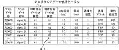
図3に示すように、プラントデータ管理テーブル24には、プラントデータIDに対応付けて、プラントデータ名称、初期担当ゲートウェイ装置、現在担当ゲートウェイ装置、初期周期、周期、通信先装置、通信プロトコル、動的優先度などが記憶されている。 As shown in FIG. 3, the plant data management table 24 shows the plant data name, the initial gateway device, the current gateway device, the initial cycle, the cycle, the communication destination device, the communication protocol, and the operation in association with the plant data ID. Target priority etc. are stored.
この例では、プラントデータID「AI0000」には、プラントデータ名称として「signalA」、初期担当ゲートウェイ装置として「#1」、現在担当ゲートウェイ装置として「#1」、初期周期として「1.0」、周期(現在設定されている更新周期)として「1.0」、通信先装置として「1」、動的優先度として「200」などが記憶されている。ここで、担当とは、どのプラントデータを中継するかを割り当てられたことを言う。初期担当とは、起動時にサーバ1によって割り当てられたときの担当または再起動したときの一つ前の担当を言う。 In this example, the plant data ID "AI0000" has the plant data name "signalA", the initial gateway device "# 1", the current gateway device "# 1", and the initial cycle "1.0". A cycle (currently set update cycle) of "1.0", a communication destination device of "1", a dynamic priority of "200", and the like are stored. Here, the person in charge means that the plant data to be relayed has been assigned. The initial charge refers to the charge assigned by the
このプラントデータ管理テーブル24は、監視中にプラント機器15〜18の運転モードが変化したり、プラントデータIDの割り当てが変化すると、それに伴って情報が更新される。例えばプラント機器15〜18の運転モードが変化すると、プラントデータ管理テーブル24の動的優先度の値が、動的優先度テーブル25のプラントデータIDの運転モードに応じた動的優先度の数値に更新される。プラントデータIDの割り当てが変化すると、それに伴ってプラントデータIDに対応する行の情報が更新される。 The information of the plant data management table 24 is updated when the operation modes of the
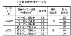
図4に示すように、動的優先度テーブル25には、プラントデータIDに対応付けて、プラント機器の運転モードに応じた重要度、静的優先度、動的優先度などが記憶されている。 As shown in FIG. 4, the dynamic priority table 25 stores the importance, static priority, dynamic priority, etc. according to the operation mode of the plant equipment in association with the plant data ID. ..
この例では、プラントデータID「AI0000」には、運転モード毎に異なる重要度が付与されている。例えば現状のプラント機器「タービン」の運転モードが「タービン起動中」の場合は、重要度「2.0」、タービンの静的優先度として固定値「100」が設定されており、重要度「2.0」とタービンの静的優先度「100」とを掛け合わせたものが動的優先度として「200」が付与されている。 In this example, the plant data ID "AI0000" is given different importance for each operation mode. For example, when the operation mode of the current plant equipment "turbine" is "turbine starting", the importance is set to "2.0", and the fixed value "100" is set as the static priority of the turbine, and the importance is "100". The product of "2.0" and the static priority "100" of the turbine is given "200" as the dynamic priority.
また、タービンの現状の運転モードが「タービン停止中」の場合は、重要度「1.0」、タービンの静的優先度として「100」が設定されているため、動的優先度としてはこれらを掛け合わせた「100」が付与されている。 When the current operation mode of the turbine is "turbine stopped", the importance is set to "1.0" and the static priority of the turbine is set to "100", so these are the dynamic priorities. "100" is given by multiplying.
さらに、タービンの現状の運転モードが「タービン運転中」の場合は、重要度「0.5」、タービンの静的優先度として「100」が設定されているため、動的優先度としては「50」が付与されている。この他、給水ポンプについても同様である。 Furthermore, when the current operation mode of the turbine is "turbine operation", the importance is set to "0.5" and the static priority of the turbine is set to "100", so that the dynamic priority is "100". 50 ”is given. The same applies to the water supply pump.
なお、図3のプラントデータ管理テーブル24と図4の動的優先度テーブル25とは、共にプラントデータIDに紐付けた情報を記憶することから、これらのテーブルを統合して、通信先装置10〜13がプラント機器15〜18から取得するプラントデータIDに対応付けて、該プラントデータIDを持つプラントデータの中継担当として割り当てられているゲートウェイ装置の識別子#1〜#n、通信先装置10〜13とゲートウェイ装置との通信情報(通信プロトコルや周期など)、プラント機器15〜18の種別毎に付与された静的優先度と、プラント機器15〜18の運転モードに応じて異なる重要度と、重要度と静的優先度とから求められる動的優先度とが記憶された記憶部としてもよい。 Since the plant data management table 24 in FIG. 3 and the dynamic priority table 25 in FIG. 4 both store information associated with the plant data ID, these tables are integrated to form the
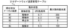
図5に示すように、ゲートウェイ装置管理テーブル26には、現在担当しているゲートウェイ装置の識別子#1〜#3…毎に、ゲートウェイ装置の稼働状態、ゲートウェイ装置の動作状態(稼働状態とCPU負荷率)、最大動的優先度などが記憶される。 As shown in FIG. 5, in the gateway device management table 26, the operating state of the gateway device and the operating state of the gateway device (operating state and CPU load) are shown for each of the
このゲートウェイ装置管理テーブル26の情報のうち動作状態(稼働状態とCPU負荷率)は監視中に更新され変化する。最大動的優先度は可変値である。最大優先度は、ゲートウェイ装置に割り当てられるプラントデータIDを持つプラントデータの中で最も大きい動的優先度の値を示すものである。このため、プラント機器の運転モードの変化によって動的優先度が下がった場合、これに追従(比例)して最大優先度の値も変化する。 Of the information in the gateway device management table 26, the operating state (operating state and CPU load factor) is updated and changed during monitoring. The maximum dynamic priority is a variable value. The maximum priority indicates the value of the highest dynamic priority among the plant data having the plant data ID assigned to the gateway device. Therefore, when the dynamic priority is lowered due to the change in the operation mode of the plant equipment, the value of the maximum priority also changes in accordance with (proportional).
割当先のゲートウェイ装置のCPU負荷率が予め設定された閾値を超える場合(高負荷の場合)に、最大動的優先度の1/2を超えるプラントデータIDがゲートウェイ装置に割り当てられる場合は、更新周期を下げる(更新期間を延ばす(長くする))など、対応が必要になる。 Update when the CPU load factor of the gateway device to be assigned exceeds a preset threshold value (in the case of high load) and a plant data ID exceeding 1/2 of the maximum dynamic priority is assigned to the gateway device. It is necessary to take measures such as lowering the cycle (extending (extending) the renewal period).
この例では、現在担当ゲートウェイ装置#1には、ゲートウェイ装置の動作状態として稼働状態が「稼働中」、CPU負荷率が「0.7」、最大動的優先度として「200」が記憶されている。割当先のゲートウェイ装置が高負荷であるときに、動的優先度が「100」を超えるプラントデータIDがゲートウェイ装置に割り当てられる場合は更新周期を下げ、CPU負荷率が変化(低下)する様子を見ることになる。 In this example, the
現在担当ゲートウェイ装置#3には、ゲートウェイ装置の状態として「停止中」、ゲートウェイ装置の負荷率として「0.1」、最大動的優先度として「150」が記憶されている。なお、このゲートウェイ装置#3のように稼働状態が「停止中」であれば、負荷率は「0」であるが、計算上の数値として「0.1」が記憶されている。 Currently, the
また、図2に示すように、サーバ1の通信監視部3には、監視部31、読取部としてのリストアップ部32、割当部として配分部33などが設けられている。 Further, as shown in FIG. 2, the
監視部31は、プラント機器15〜18および複数のゲートウェイ装置#1〜#nの動作状態を予め設定された更新周期(例えば1分に1回)毎に監視し、ゲートウェイ装置管理テーブル26の現在担当ゲートウェイ装置#1〜#nそれぞれの動作状態(稼働状態およびCPU負荷率)を更新するとともに、更新したゲートウェイ装置管理テーブル26から、停止中またはCPU負荷率が一定値(例えば0.8)以上の高負荷のゲートウェイ装置(このテーブルの例ではゲートウェイ装置#3)を検出する。 The
リストアップ部32は、プラントデータ管理テーブル24を参照して、監視部31により停止中または高負荷として検出されたゲートウェイ装置に割り当てられているプラントデータIDと検出時の運転モードに応じた動的優先度を読み出しリストアップする。 The list-up
配分部33は、リストアップ部32によりリストアップされたリストのプラントデータIDの動的優先度を基に、プラントデータ管理テーブル24およびゲートウェイ装置管理テーブル26を参照して、停止中のゲートウェイ装置が担当しているプラントデータIDを、現在稼働中のCPU負荷率の低い他のゲートウェイ装置に割り当てる。また、配分部33は、高負荷として検出されたゲートウェイ装置のプラントデータの更新周期を延ばす。 The
この例では、停止中のゲートウェイ装置#3が担当しているプラントデータIDは、プラントデータ管理テーブル24の「DI0001」であり、現在稼働中のCPU負荷率の低い他のゲートウェイ装置は、ゲートウェイ装置管理テーブル26よりゲートウェイ装置#2(CPU負荷率「0.2」)なので、これにプラントデータID「DI0001」を割り当て、プラントデータ管理テーブル24を更新する。更新したプラントデータ管理テーブル24の状態が図3の符号41の状態である。 In this example, the plant data ID in charge of the stopped
また、配分部33は、割当先のゲートウェイ装置のCPU負荷率が予め設定された閾値を超える場合、割当先のゲートウェイ装置において現在担当しているプラントデータIDに付与されている最大動的優先度を基に判定した動的優先度の低いプラントデータの識別情報から順に更新周期を予め設定された割合で延ばし、割当先のゲートウェイ装置のCPU負荷率が閾値以下に低下したら割当対象のプラントデータの識別情報を割当先のゲートウェイ装置に割り当てる。 Further, when the CPU load factor of the allocation destination gateway device exceeds a preset threshold value, the
配分部33は、プラントデータIDを割当先のゲートウェイ装置へ割り当てた後、割当先のゲートウェイ装置を監視した結果、現在のCPU負荷率からプラントデータIDを割当可能なCPU負荷率の上限値(閾値「0.8」など)までに一定の差(0.3以上)があった場合に、割当先のゲートウェイ装置において動的優先度の高いプラントデータから順に更新周期を元の更新周期に戻す。 After allocating the plant data ID to the gateway device of the allocation destination, the
配分部33は、停止中または高負荷として検出されたゲートウェイ装置が復帰またはCPU負荷率が一定値未満に戻った場合、割当先のゲートウェイ装置に割当済のプラントデータIDを、復帰またはCPU負荷率が一定値未満に戻ったゲートウェイ装置に割り当て直す。 When the gateway device detected as stopped or high load returns or the CPU load factor returns to less than a certain value, the
配分部33は、監視部31により現在担当または割当先のゲートウェイ装置が高負荷と検出された場合、動的優先度が低いプラントデータIDから順に更新周期を予め設定された割合(例えば10%程度)で延ばす。 When the
次に、この実施形態のプラントデータ監視システムの動作を説明する。
まず、図6を参照してシステム起動時の動作を説明する。
この場合、各ゲートウェイ装置#1〜#nは、起動したときに(図6のステップS101)、サーバ1に対して担当割り当て要求を送信する(図6のステップS102)。Next, the operation of the plant data monitoring system of this embodiment will be described.
First, the operation at system startup will be described with reference to FIG.
In this case, when the
サーバ1では、通信監視部3が、各ゲートウェイ装置#1〜#nからの担当割り当て要求を受け付けて(ステップS103)、構成管理用データベース2にアクセスし、プラントデータ管理テーブル24を参照して、現在担当ゲートウェイ装置の列が、要求されたゲートウェイ装置の割り当て番号(例えば、ゲートウェイ装置#1の場合は識別子が「#1」)となるプラントデータIDに対応する、プラントデータ名称、周期(ms)、通信先装置、通信プロトコルなどを含むプラントデータ管理情報を一つにまとめた割当情報としてそれぞれの現在担当ゲートウェイ装置毎に取得し(ステップS104)、要求元のゲートウェイ装置#1〜#nに返す(ステップS105)。 In the
それぞれのゲートウェイ装置#1〜#nは、サーバ1からプラントデータの割当情報を受信すると(ステップS106)、取得したプラントデータの割当情報に従って、ネットワーク9を通じて、該当する通信先装置10〜13に対してプラントデータの取得要求を送信する(ステップS107)。 When the respective
それぞれの通信先装置10〜13は、プラントデータの取得要求を受信すると(ステップS108)、要求送信元のゲートウェイ装置#1〜#nに対して、要求されたプラントIDに対応するプラントデータを、要求に含まれる周期(ms)で取得し(ステップS109)、要求に含まれる通信プロトコルにてネットワーク9を通じて、要求元のゲートウェイ装置#1〜#nに返す(ステップS110)。 When each of the
各ゲートウェイ装置#1〜#nは、それぞれの通信先装置10〜13からプラントデータを受信すると(ステップS111)、取得したプラントデータを、ネットワーク4を通じてサーバ1へ送信、つまりデータを中継する(ステップS112)。 When each of the
サーバ1では、通信監視部3が、プラントデータを受信すると(ステップS113)、受信したプラントデータを構成管理用データベース2に記憶する(ステップS114)。 When the
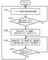
続いて、図7を参照してプラントデータ監視システムの監視動作を説明する。
この場合、サーバ1では、通信監視部3が予め設定された一定の周期(例えば、1分に1回)毎にゲートウェイ装置の稼働状態を確認する(図7のステップS201)。Subsequently, the monitoring operation of the plant data monitoring system will be described with reference to FIG. 7.
In this case, in the
この際、通信監視部3は、ゲートウェイ装置管理テーブル26の中に存在する、各ゲートウェイ装置の稼働状態を示すパラメータが“稼働中”か“停止中”かを確認する。 At this time, the
この確認の結果、ゲートウェイ装置の状態が“停止中”となっている現在担当ゲートウェイ装置が存在する場合(ステップS202のYes)、通信監視部3は、プラントデータ管理テーブル24を確認し、その“停止中”の現在担当ゲートウェイ装置に対応するプラントデータIDをリストアップする(ステップS203)。 As a result of this confirmation, if there is a gateway device currently in charge whose gateway device status is "stopped" (Yes in step S202), the
そして、通信監視部3は、リストアップしたプラントデータIDの中で、動的優先度の高いプラントデータから優先的に、ゲートウェイ装置管理テーブル26のCPU負荷率の低いゲートウェイ装置に配分していく(プラントデータIDの現在担当ゲートウェイ装置を変更する)(ステップS204)。 Then, the
そして、今回の分のプラントデータIDの配分が終了すると(ステップS205のYes)、ステップS201の監視状態に戻る。 Then, when the distribution of the plant data ID for this time is completed (Yes in step S205), the process returns to the monitoring state in step S201.
プラントデータIDの配分の仕方の一例としては、例えば動的優先度の値が予め設定された閾値以上(例えば、閾値として100が設定されている場合は100以上)のプラントデータIDから優先的に、ゲートウェイ装置負荷率の最も低いゲートウェイ装置に配分する。負荷率は小数点で表しても%で表してもよい。 As an example of how to allocate the plant data ID, for example, priority is given to the plant data ID whose dynamic priority value is equal to or higher than a preset threshold value (for example, 100 or more when 100 is set as the threshold value). , Gateway device Allocate to the gateway device with the lowest load factor. The load factor may be expressed in decimal points or%.
ここで、動的優先度は、数値が大きいほど優先度が高いことを示し、この動的優先度は次に示す方法(計算式)で求めた値が動的優先度テーブル25に設定される。 Here, the dynamic priority indicates that the higher the numerical value, the higher the priority, and the value obtained by the method (calculation formula) shown below is set in the dynamic priority table 25. ..
動的優先度=静的優先度×重要度
なお、静的優先度とは、プラントデータ毎に予めプラント機器15〜18の種別(タービン、給水ポンプなど)に応じて設定されるプラント内での機器の役割りの優先度を示す係数(パラメータ)である。また「重要度」は、プラントデータ毎にプラント機器の運転モードに応じて、予め設定された係数(パラメータ)である。図4の動的優先度テーブル25の例では、プラント機器が例えばタービンの場合“起動中”は「2.0」、“停止中”は「1.0」、“運転中”は「0.5」などと設定されている。Dynamic priority = static priority x importance Note that the static priority is set in advance for each plant data according to the types of
動的優先度は、プラント監視システム起動後、現状の運転モードに対応した重要度と静的優先度とを掛け合わせた値である。 The dynamic priority is a value obtained by multiplying the importance corresponding to the current operation mode and the static priority after the plant monitoring system is started.
このとき、通信監視部3がCPU負荷率を確認するタイミングは、一定周期(例えば、10秒に1回)とする。これにより、ゲートウェイ装置の故障も含めた停止状態を検知してから、例えば、5分(300秒)以内にプラントデータの配分完了を目標性能とした場合には、次の手順によって、1度に「現在担当ゲートウェイ装置」を変更するプラントデータ数を決定する。 At this time, the timing at which the
これは、プラントデータを1本ずつ配分する仕組みにしてしまうと、プラントデータをすべて配分するまでに非常に長い時間を要してしまうことになり、その間のプラントデータの監視も欠損してしまうため、何本かまとめて配分処理を行う仕組みとしている。 This is because if the system is to allocate plant data one by one, it will take a very long time to allocate all the plant data, and the monitoring of plant data during that time will also be lost. , It is a mechanism to distribute several pieces at once.
故障も含めた停止状態となったゲートウェイ装置を例えば1000個のプラントデータが中継していた場合、(1000÷300)×10(秒)=33.333...となる。 For example, when 1000 plant data are relaying the gateway device that has been stopped including the failure, (1000 ÷ 300) × 10 (seconds) = 33.333. .. .. Will be.
この計算結果より、1000個のプラントデータを5分以内に10秒間隔で配分する場合に配分1回につき34本以上のプラントデータを現在担当ゲートウェイ装置のいずれかに配分して担当変更する必要がある。 From this calculation result, when allocating 1000 plant data within 5 minutes at 10-second intervals, it is necessary to allocate 34 or more plant data to one of the gateway devices currently in charge and change the responsibilities. is there.
ここで、ゲートウェイ装置のCPU負荷率とは、ゲートウェイ装置毎のCPU負荷率の移動平均値から求める係数(パラメータ)である。 Here, the CPU load factor of the gateway device is a coefficient (parameter) obtained from the moving average value of the CPU load factor for each gateway device.
CPU負荷率の係数(パラメータ)の求め方は次の通りである。
(求め方):1秒間毎のCPU負荷率を時系列データとして取得し、直近の5個のデータの平均を計算し、CPU負荷率の移動平均値として求めた値をゲートウェイ装置負荷率とする。The method of obtaining the coefficient (parameter) of the CPU load factor is as follows.
(How to obtain): Acquire the CPU load factor every second as time-series data, calculate the average of the latest 5 data, and use the value obtained as the moving average value of the CPU load factor as the gateway device load factor. ..
なお、ゲートウェイ装置負荷率が同じゲートウェイ装置が2台以上存在した場合には、ゲートウェイ装置番号の小さいものから優先的に配分先に選定する。 If there are two or more gateway devices with the same gateway device load factor, the one with the smallest gateway device number is preferentially selected as the allocation destination.
また、動的優先度が閾値に満たない(例えば、100未満)のプラントデータは、配分前に更新周期を所定の割合(例えば10%)下げてから、そのときゲートウェイ装置のCPU負荷率の最も低いゲートウェイ装置に配分する(プラントデータの現在担当ゲートウェイを変更してゆく)。更新周期を10%下げるとは、更新周期を10%延ばすことを意味する。 Further, for plant data whose dynamic priority is less than the threshold value (for example, less than 100), the update cycle is lowered by a predetermined ratio (for example, 10%) before allocation, and then the CPU load factor of the gateway device is the highest. Allocate to lower gateway devices (change the current gateway of plant data). Decreasing the update cycle by 10% means extending the update cycle by 10%.
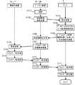
ここで、図8を参照してプラント機器の運転モードやゲートウェイ装置の動作状態に応じた配分部33の動作を説明する。 Here, the operation of the
この場合、監視部31が、監視中、ゲートウェイ装置管理テーブル26にて現在担当しているゲートウェイ装置の動作状態を確認した結果、現在担当ゲートウェイ装置のうち、いずれかの装置の稼働状態が「停止中」(故障を含む停止状態)か、CPU負荷率が高い状態(高負荷状態)かを判定し、判定結果に応じて異なる処理を行う(ステップS301〜S303)。 In this case, as a result of the
例えばある現在担当ゲートウェイ装置の稼働状態が「停止中」でなく、高負荷状態の場合(ステップS301のNo、ステップS302のYes)、配分部33は、ゲートウェイ装置管理テーブル26の高負荷の該当現在担当ゲートウェイ装置に設定されている最大動的優先度を基に、現在担当している動的優先度の低いプラントデータIDから順に更新周期(1分間の1回など)を予め設定された割合(例えば10%など)で延ばすようプラントデータ管理テーブル24の周期(ms)の設定を変更する(ステップS303)。 For example, when the operating state of a certain gateway device in charge is not "stopped" but in a high load state (No in step S301, Yes in step S302), the
また、ある現在担当ゲートウェイ装置の稼働状態が「停止中」の場合(ステップS301のYes)、配分部33は、ゲートウェイ装置管理テーブル26の他のゲートウェイ装置それぞれのCPU負荷率を基に、配分先となるゲートウェイ装置に余裕があるか否かを判定する(ステップS304)。具体的には各CPU負荷率と予め設定された閾値(配分先となることが可能なCPU負荷率の限界値)とを比較して差分値の大きいものほど余裕があるものと判定する。 Further, when the operating state of a certain gateway device in charge is "stopped" (Yes in step S301), the
ステップS304の判定の結果、配分先の現在担当ゲートウェイ装置のCPU負荷率に余裕がない場合(ステップS304のNo)、配分部33は、配分先の現在担当ゲートウェイ装置が担当しているプラントデータIDの更新周期を上記ステップS303と同様に延ばすようプラントデータ管理テーブル24の周期(ms)の設定を変更する(ステップS305)。 As a result of the determination in step S304, when there is no margin in the CPU load factor of the gateway device currently in charge of the allocation destination (No in step S304), the
周期(ms)の設定を変更する際に、配分部33は、ゲートウェイ装置管理テーブル26の現在担当ゲートウェイ装置に設定されている最大動的優先度を基に、現在担当している動的優先度の低いプラントデータIDから順に更新周期を予め設定された割合(例えば10%など)で延ばすようプラントデータ管理テーブル24の周期(ms)の設定を変更する。 When changing the cycle (ms) setting, the
そして、配分先のゲートウェイ装置のCPU負荷率が閾値以下に低下し、余裕ができたことが確認されると(ステップS304のYes)、割当対象のプラントデータIDの動的優先度を基に、割当対象のプラントデータIDを、配分先のゲートウェイ装置に割り当てる、つまり動的優先度を基にプラントデータIDを配分する(ステップS306)。 Then, when it is confirmed that the CPU load factor of the gateway device at the allocation destination has dropped below the threshold value and a margin has been established (Yes in step S304), based on the dynamic priority of the plant data ID to be allocated, The plant data ID to be assigned is assigned to the gateway device of the allocation destination, that is, the plant data ID is allocated based on the dynamic priority (step S306).
また、上記ステップS304の判定の結果、配分先の現在担当ゲートウェイ装置のCPU負荷率に余裕がある場合(ステップS304のYes)、配分部33は、CPU負荷率が余裕のある現在担当ゲートウェイ装置のうちCPU負荷率が低いゲートウェイ装置に優先的に「停止中」の現在担当ゲートウェイ装置が担当しているプラントデータIDのうち動的優先度が高い順にプラントデータIDを割り当る、つまり動的優先度を基にプラントデータIDを配分する(ステップS306)。 Further, as a result of the determination in step S304, when the CPU load factor of the current charge gateway device of the allocation destination has a margin (Yes in step S304), the
図5のゲートウェイ装置管理テーブル26の例で、配分先となるためのゲートウェイ装置のCPU負荷率の閾値が「0.8」とすると、現在担当ゲートウェイ装置#3が「停止中」であり、他の現在担当ゲートウェイ装置#2と現在担当ゲートウェイ装置#1が「稼働中」で閾値「0.8」以下のためプラントデータの配分先となれるが、現在担当ゲートウェイ装置#2のCPU負荷率が「0.2」、現在担当ゲートウェイ装置#1のCPU負荷率が「0.7」では、現在担当ゲートウェイ装置#2のCPU負荷率「0.2」の方が閾値「0.8」に対して余裕があるため、現在担当ゲートウェイ装置#3の動的優先度の高いプラントデータIDは、現在担当ゲートウェイ装置#2に配分されることになる。 In the example of the gateway device management table 26 of FIG. 5, if the threshold of the CPU load factor of the gateway device to be the allocation destination is "0.8", the
「停止中」の現在担当ゲートウェイ装置が担当しているプラントデータIDの配分を順に行った際に、配分できないものがあった場合(配分対象のプラントデータIDをすべて配分し切れない場合)(ステップS307のNo)、配分部33は、「停止中」の現在担当ゲートウェイ装置が担当しているプラントデータIDの更新周期を上記ステップS303と同様に延ばすようプラントデータ管理テーブル24の周期(ms)の設定を変更する(ステップS308)。 When the plant data IDs currently in charge of the "stopped" gateway device are allocated in order, if there is something that cannot be allocated (when all the plant data IDs to be allocated cannot be allocated) (step) S307 No), the
配分がすべて終了すると(ステップS307のYes)、配分完了後に、監視されて更新されたゲートウェイ装置管理テーブル26の配分先のゲートウェイ装置のCPU負荷率から、配分先のゲートウェイ装置に余裕があるか(閾値以下または閾値よりも一定の差があるか)否かを確認する(ステップS309)。 When all the allocation is completed (Yes in step S307), is there a margin in the allocation destination gateway device from the CPU load factor of the allocation destination gateway device in the monitored and updated gateway device management table 26 after the allocation is completed? It is confirmed whether or not there is a certain difference below the threshold value or above the threshold value (step S309).
この確認の結果、配分完了後に、配分先のゲートウェイ装置に余裕がある場合(ステップS309のYes)、配分部33は、プラントデータ管理テーブル24を参照して、配分したプラントデータIDの中で、配分前に更新周期を下げていた、動的優先度の値が高いプラントデータIDから順にプラントデータ管理テーブル24の「周期(ms)」に、「初期周期(ms)」と同じ値を設定し、更新周期を元の更新周期に戻す(ステップS310)。この処理をCPU負荷率が閾値(例えば0.8)以上になるまで実行していく。 As a result of this confirmation, if there is a margin in the gateway device of the allocation destination after the allocation is completed (Yes in step S309), the
その後、「停止中」の現在担当ゲートウェイ装置が修理または交換されるなどして復帰した場合、配分部33は、プラントデータ管理テーブル24の初期担当ゲートウェイ装置を基に、復帰したゲートウェイ装置に復帰前に担当していたプラントデータIDを戻すように、プラントデータ管理テーブル24の現在担当ゲートウェイ装置の識別子の設定を変更する。具体的には、プラントデータ管理テーブル24において、復帰したゲートウェイ装置(初期担当ゲートウェイ装置)の識別子が「#3」の場合、プラントデータ管理テーブル24のプラントデータID「DI0001」の現在担当ゲートウェイ装置の識別子を「#2」から「#3」に変更する。 After that, when the "stopped" current gateway device is restored by repair or replacement, the
このようにこの実施形態のプラントデータ監視システムによれば、プラント機器15〜18の運転モードに応じて変化する動的優先度という概念を導入し、複数のゲートウェイ装置#1〜#nのうちいずれかの装置が故障も含めた停止状態に陥った場合、「停止中」(停止状態)のゲートウェイ装置が担当していたプラントデータIDを動的優先度が高い順に他の稼働中のゲートウェイ装置に配分するので、故障も含めた停止状態となったゲートウェイ装置が中継していたプラントデータを継続して取得することができ、複数のプラントデータの継続的な監視が可能になる。すなわち、複数のゲートウェイ装置#1〜#nの中の1つが停止したときに、そのゲートウェイ装置が中継していたプラントデータの欠損を最低限にとどめて監視を継続することができる。 As described above, according to the plant data monitoring system of this embodiment, the concept of dynamic priority that changes according to the operation mode of the
上記実施形態では、現在担当ゲートウェイ装置のうち「停止中」(停止状態)のゲートウェイ装置に対して他の稼働中のゲートウェイ装置にプラントデータIDの割り当て変更を行い、CPU負荷率が一定の閾値以上の高負荷のゲートウェイ装置には更新周期を延ばすことで負荷軽減を行ったが、一定の閾値以上に高負荷に陥ったゲートウェイ装置に対して更新周期を延ばすことなく他の稼働中のゲートウェイ装置に割り当て変更を行ってもよい。 In the above embodiment, the plant data ID is assigned to another operating gateway device for the "stopped" (stopped state) gateway device among the currently responsible gateway devices, and the CPU load factor is equal to or higher than a certain threshold value. The load was reduced by extending the update cycle for the high-load gateway device, but for the gateway device that has fallen into a high load above a certain threshold, the update cycle is not extended to other operating gateway devices. You may change the allocation.
また、高負荷として検出された現在担当ゲートウェイ装置の更新周期を下げることを繰り返し実施してもCPU負荷率が閾値以下にならない場合は、動的優先度の低いプラントデータIDから順に、そのときCPU負荷率が最も低い稼働中の他のゲートウェイ装置に現在担当ゲートウェイ装置を変更してもよい。 If the CPU load factor does not fall below the threshold even after repeatedly reducing the update cycle of the gateway device currently in charge detected as a high load, the CPU at that time is in order from the plant data ID with the lowest dynamic priority. The gateway device currently in charge may be changed to another gateway device in operation with the lowest load factor.
本発明の実施形態を説明したが、この実施形態は、例として提示したものであり、発明の範囲を限定することは意図していない。この新規な実施形態は、その他の様々な形態で実施されることが可能であり、発明の要旨を逸脱しない範囲で、種々の省略、置き換え、変更を行うことができる。この実施形態やその変形は、発明の範囲や要旨に含まれるとともに、特許請求の範囲に記載された発明とその均等の範囲に含まれる。 Although embodiments of the present invention have been described, these embodiments are presented as examples and are not intended to limit the scope of the invention. This novel embodiment can be implemented in various other embodiments, and various omissions, replacements, and changes can be made without departing from the gist of the invention. This embodiment and its modifications are included in the scope and gist of the invention, and are also included in the scope of the invention described in the claims and the equivalent scope thereof.
また上記実施形態に示した監視用のサーバ1の各構成要素を、コンピュータのハードディスク装置などのストレージにインストールしたプログラムで実現してもよく、また上記プログラムを、コンピュータ読取可能な電子媒体:electronic mediaに記憶しておき、プログラムを電子媒体からコンピュータに読み取らせることで本発明の機能をコンピュータが実現するようにしてもよい。電子媒体としては、例えばCD−ROM等の記録媒体やフラッシュメモリ、リムーバブルメディア:Removable media等が含まれる。さらに、ネットワークを介して接続した異なるコンピュータに構成要素を分散して記憶し、各構成要素を機能させたコンピュータ間で通信することで実現してもよい。 Further, each component of the
1…コンピュータ(監視用のサーバ)、2…構成管理用データベース、3…通信監視部、4、9…ネットワーク、10〜13…通信先装置、15〜18…プラント機器、#1〜#n…ゲートウェイ装置、24…プラントデータ管理テーブル、25…動的優先度テーブル、26…ゲートウェイ装置管理テーブル、31…監視部、32…リストアップ部、33…配分部。 1 ... Computer (monitoring server), 2 ... Configuration management database, 3 ... Communication monitoring unit, 4, 9 ... Network, 10 to 13 ... Communication destination device, 15 to 18 ... Plant equipment, # 1 to # n ... Gateway device, 24 ... Plant data management table, 25 ... Dynamic priority table, 26 ... Gateway device management table, 31 ... Monitoring unit, 32 ... Listing unit, 33 ... Allocation unit.
Claims (7)
Translated fromJapanese前記監視用のコンピュータが、
前記データ取得装置が前記データ発生源の機器から取得するプラントデータの識別情報に、該プラントデータの中継担当として割り当てられているゲートウェイ装置の識別情報と、前記データ発生源の機器の種別毎に付与された静的優先度と、前記データ発生源の機器の運転モードに応じた重要度と、前記重要度と前記静的優先度とから求められる動的優先度とが対応付けて記憶された記憶部と、
前記データ発生源の機器および前記複数のゲートウェイ装置の動作状況を予め設定された更新周期毎に監視し、前記データ発生源の機器の現在の運転モードと、停止中またはCPU負荷率が一定値以上の高負荷のゲートウェイ装置を検出する監視部と、
前記記憶部を参照し、前記監視部により前記停止中または高負荷として検出されたゲートウェイ装置に割り当てられているプラントデータの識別情報と検出時の運転モードに応じた動的優先度を基に、前記停止中または高負荷のゲートウェイ装置が担当しているプラントデータの識別情報を、現在稼働中の他のゲートウェイ装置に割り当てる割当部と
を具備するプラントデータ監視システム。A plant data monitoring system in which a computer for monitoring, a plurality of gateway devices, and a plurality of data acquisition devices provided in a data source device operating in a plant are connected via a network.
The monitoring computer
The identification information of the gateway device assigned as the relay charge of the plant data and the identification information of the gateway device assigned to the identification information of the plant data acquired by the data acquisition device from the device of the data source are added to each type of the device of the data source. A storage in which the static priority obtained, the importance according to the operation mode of the device of the data source, and the dynamic priority obtained from the importance and the static priority are associated and stored. Department and
The operating status of the data source device and the plurality of gateway devices is monitored at preset update cycles, and the current operation mode of the data source device and the stopped or CPU load factor are equal to or higher than a certain value. A monitoring unit that detects high-load gateway devices in
With reference to the storage unit, based on the identification information of the plant data assigned to the gateway device detected as stopped or high load by the monitoring unit and the dynamic priority according to the operation mode at the time of detection. A plant data monitoring system including an allocation unit that allocates identification information of plant data in charge of the stopped or high-load gateway device to other gateway devices currently in operation.
前記動的優先度の高いプラントデータの識別情報から順に、他の稼働中の前記ゲートウェイ装置のCPU負荷率が低いゲートウェイ装置に前記プラントデータの識別情報を割り当てる請求項1記載のプラントデータ監視システム。The allocation unit
The plant data monitoring system according to claim 1, wherein the identification information of the plant data is assigned to other gateway devices having a low CPU load factor of the gateway device in operation in order from the identification information of the plant data having the highest dynamic priority.
割当先のゲートウェイ装置のCPU負荷率が予め設定された閾値を超える場合、前記割当先のゲートウェイ装置において現在担当しているプラントデータの識別情報に付与されている最大動的優先度を基に判定した動的優先度の低いプラントデータの識別情報から順に更新周期を予め設定された割合で延ばし、前記割当先のゲートウェイ装置のCPU負荷率が閾値以下に低下したら割当対象のプラントデータの識別情報を前記割当先のゲートウェイ装置に割り当てる請求項1記載のプラントデータ監視システム。The allocation unit
When the CPU load factor of the allocation destination gateway device exceeds a preset threshold, the determination is made based on the maximum dynamic priority given to the identification information of the plant data currently in charge of the allocation destination gateway device. The update cycle is extended at a preset rate in order from the identification information of the plant data with the lowest dynamic priority, and when the CPU load factor of the gateway device of the allocation destination drops below the threshold, the identification information of the plant data to be allocated is added. The plant data monitoring system according to claim 1, which is assigned to the gateway device of the allocation destination.
前記プラントデータの識別情報を割当先のゲートウェイ装置へ割り当てた後、前記割当先のゲートウェイ装置を監視した結果、現在のCPU負荷率からCPU負荷率の上限値までに一定の差があった場合に、前記割当先のゲートウェイ装置において動的優先度の高いプラントデータから順に更新周期を元の更新周期に戻す請求項3記載のプラントデータ監視システム。The allocation unit
When there is a certain difference between the current CPU load factor and the upper limit of the CPU load factor as a result of monitoring the gateway device of the allocation destination after allocating the identification information of the plant data to the gateway device of the allocation destination. The plant data monitoring system according to claim 3, wherein the update cycle is returned to the original update cycle in order from the plant data having the highest dynamic priority in the gateway device of the allocation destination.
前記停止中または高負荷として検出されたゲートウェイ装置が復帰またはCPU負荷率が一定値以下に戻った場合、割当先のゲートウェイ装置に割当済のプラントデータの識別情報を、復帰またはCPU負荷率が一定値以下に戻ったゲートウェイ装置に割り当て直す請求項1記載のプラントデータ監視システム。The allocation unit
When the gateway device detected as stopped or high load returns or the CPU load factor returns to a certain value or less, the identification information of the plant data allocated to the assigned gateway device is returned or the CPU load factor is constant. The plant data monitoring system according to claim 1, wherein the gateway device is reassigned to a gateway device that has returned below the value.
前記監視部により現在担当または割当先のゲートウェイ装置が高負荷と検出された場合前記動的優先度が低いプラントデータの識別情報から順に更新周期を予め設定された割合で延ばす請求項1記載のプラントデータ監視システム。The allocation unit
The plant according to claim 1, wherein when the monitoring unit detects that the gateway device currently in charge or the assigned destination has a high load, the update cycle is extended in order from the identification information of the plant data having the lowest dynamic priority at a preset rate. Data monitoring system.
前記監視用のコンピュータが、前記データ取得装置が前記データ発生源の機器から取得するプラントデータの識別情報に、該プラントデータの中継担当として割り当てられているゲートウェイ装置の識別情報と、前記データ発生源の機器の種別毎に付与された静的優先度と、前記データ発生源の機器の運転モードに応じた重要度と、前記重要度と前記静的優先度とから求められる動的優先度とを対応付けて記憶し、
監視用のコンピュータが、前記データ発生源の機器および前記複数のゲートウェイ装置の動作状況を予め設定された更新周期毎に監視し、前記データ発生源の機器の現在の運転モードと、停止中またはCPU負荷率が一定値以上の高負荷のゲートウェイ装置を検出し、
監視用のコンピュータが、前記停止中または高負荷として検出したゲートウェイ装置に割り当てられているプラントデータの識別情報と検出時の運転モードに応じた動的優先度を基に、前記停止中または高負荷のゲートウェイ装置が担当しているプラントデータの識別情報を、現在稼働中の他のゲートウェイ装置に割り当てる、プラントデータ監視方法。It is a plant data monitoring method in a plant data monitoring system in which a computer for monitoring, a plurality of gateway devices, and a plurality of data acquisition devices provided in a data source device operating in a plant are connected via a network. ,
The monitoring computer uses the identification information of the gateway device assigned as the relay person in charge of the plant data to the identification information of the plant data acquired by the data acquisition device from the device of the data source, and the data source. The static priority assigned to each type of device, the importance according to the operation mode of the device of the data source, and the dynamic priority obtained from the importance and the static priority. Correspond and memorize
A monitoring computer monitors the operating status of the data source device and the plurality of gateway devices at preset update cycles, and the current operation mode of the data source device and the stopped or CPU. Detects a gateway device with a high load whose load factor is above a certain value,
The stopped or high load is based on the identification information of the plant data assigned to the gateway device detected by the monitoring computer as stopped or high load and the dynamic priority according to the operation mode at the time of detection. A plant data monitoring method that assigns the identification information of the plant data that the gateway device is in charge of to other gateway devices that are currently in operation.
Priority Applications (1)
| Application Number | Priority Date | Filing Date | Title |
|---|---|---|---|
| JP2019089861AJP2020187413A (en) | 2019-05-10 | 2019-05-10 | Plant data monitoring system and plant data monitoring method |
Applications Claiming Priority (1)
| Application Number | Priority Date | Filing Date | Title |
|---|---|---|---|
| JP2019089861AJP2020187413A (en) | 2019-05-10 | 2019-05-10 | Plant data monitoring system and plant data monitoring method |
Publications (1)
| Publication Number | Publication Date |
|---|---|
| JP2020187413Atrue JP2020187413A (en) | 2020-11-19 |
Family
ID=73221778
Family Applications (1)
| Application Number | Title | Priority Date | Filing Date |
|---|---|---|---|
| JP2019089861APendingJP2020187413A (en) | 2019-05-10 | 2019-05-10 | Plant data monitoring system and plant data monitoring method |
Country Status (1)
| Country | Link |
|---|---|
| JP (1) | JP2020187413A (en) |
Cited By (1)
| Publication number | Priority date | Publication date | Assignee | Title |
|---|---|---|---|---|
| JP2023157157A (en)* | 2022-04-14 | 2023-10-26 | 三菱電機株式会社 | Surveillance systems and gateway devices |
- 2019
- 2019-05-10JPJP2019089861Apatent/JP2020187413A/enactivePending
Cited By (2)
| Publication number | Priority date | Publication date | Assignee | Title |
|---|---|---|---|---|
| JP2023157157A (en)* | 2022-04-14 | 2023-10-26 | 三菱電機株式会社 | Surveillance systems and gateway devices |
| JP7738517B2 (en) | 2022-04-14 | 2025-09-12 | 三菱電機株式会社 | Monitoring system and gateway device |
Similar Documents
| Publication | Publication Date | Title |
|---|---|---|
| TWI516904B (en) | Power allotment distribution in a data center | |
| JP4580423B2 (en) | Sensor network management method | |
| US7441133B2 (en) | Rack level power management for power over Ethernet | |
| US20030041137A1 (en) | Home gateway apparatus | |
| US20050272402A1 (en) | Method for rapid port power reduction | |
| US20150066185A1 (en) | Fail-over system and method for a semiconductor equipment server | |
| JP6720836B2 (en) | SIM management device | |
| JP2020187413A (en) | Plant data monitoring system and plant data monitoring method | |
| JP2016023843A (en) | Hot water supply equipment management device, hot water supply equipment management method, hot water supply equipment management program, and hot water supply equipment management system | |
| CN103825789B (en) | Bus system and its operation method and the fluidic system with bus system | |
| JP6114101B2 (en) | Plant control system and plant control method | |
| CN101308467A (en) | Task processing method and device | |
| US20250132951A1 (en) | Methods, systems and devices for coordinating a plurality of nodes in a 10base-t1s ethernet network | |
| CN101825991A (en) | Method and system using range bandwidth for controlling disk i/o | |
| JP6906301B2 (en) | Monitoring and control system update method, monitoring and control system and control method | |
| CN111752675B (en) | Internet of things platform based on containerization technology | |
| CN110618664B (en) | Decentralized distributed control system and control method thereof | |
| JP2018093573A (en) | Storage battery control device, storage battery control system, storage battery control method, and program | |
| JP7201341B2 (en) | Power regulation controller and method | |
| JP2017055302A (en) | Apparatus information management system | |
| JP4743904B2 (en) | Resource over-distribution prevention system | |
| JP2009026182A (en) | Program execution system and execution apparatus | |
| US11635923B2 (en) | Monitoring system, monitoring method, and monitoring program | |
| CN110855465B (en) | Message processing method and device | |
| JP2017175706A (en) | Power storage system and controller |