JP2020180508A - Handrail support column support tool - Google Patents
Handrail support column support toolDownload PDFInfo
- Publication number
- JP2020180508A JP2020180508AJP2019085121AJP2019085121AJP2020180508AJP 2020180508 AJP2020180508 AJP 2020180508AJP 2019085121 AJP2019085121 AJP 2019085121AJP 2019085121 AJP2019085121 AJP 2019085121AJP 2020180508 AJP2020180508 AJP 2020180508A
- Authority
- JP
- Japan
- Prior art keywords
- handrail
- support
- strut
- base plate
- reinforcing bar
- Prior art date
- Legal status (The legal status is an assumption and is not a legal conclusion. Google has not performed a legal analysis and makes no representation as to the accuracy of the status listed.)
- Pending
Links
- 230000003014reinforcing effectEffects0.000claimsdescription48
- 210000003205muscleAnatomy0.000claimsdescription3
- 230000002787reinforcementEffects0.000abstractdescription13
- 238000009415formworkMethods0.000description7
- 239000004567concreteSubstances0.000description6
- 229910000831SteelInorganic materials0.000description4
- 239000010959steelSubstances0.000description4
- 239000000463materialSubstances0.000description3
- 239000011150reinforced concreteSubstances0.000description2
- 238000010276constructionMethods0.000description1
- 239000002184metalSubstances0.000description1
- 238000000034methodMethods0.000description1
- 238000012986modificationMethods0.000description1
- 230000004048modificationEffects0.000description1
Images


Landscapes
- Steps, Ramps, And Handrails (AREA)
Abstract
Description
Translated fromJapanese本発明は、梁鉄筋組立体に装着されて手摺支柱を支持する手摺支柱支持具に関する。 The present invention relates to a handrail strut support that is attached to a beam reinforcing bar assembly to support a handrail strut.
商業施設やオフィスビル等の建築物は、鉄筋コンクリート製の躯体構造物により建築される。躯体構造物は、建築物の鉄骨柱を支持する躯体支柱と、この躯体支柱に水平に連結される躯体梁と、躯体梁に取り付けられる床スラブとを有している。このような躯体構造物を構築するには、躯体支柱を構成する柱鉄筋組立体、躯体梁を構成する梁鉄筋組立体、および床スラブを構成するスラブ鉄筋組立体がそれぞれ組み立てられる。それぞれの鉄筋組立体には型枠が配置され、型枠内にはコンクリートが流し込まれ、コンクリートと鉄筋組立体とからなる躯体構造物が構築される。 Buildings such as commercial facilities and office buildings are constructed with reinforced concrete skeleton structures. The skeleton structure has a skeleton column that supports the steel column of the building, a skeleton beam that is horizontally connected to the skeleton column, and a floor slab that is attached to the skeleton beam. In order to construct such a skeleton structure, a column reinforcing bar assembly constituting a skeleton column, a beam reinforcing bar assembly constituting a skeleton beam, and a slab reinforcing bar assembly constituting a floor slab are assembled. A formwork is arranged in each reinforcing bar assembly, concrete is poured into the formwork, and a skeleton structure composed of concrete and the reinforcing bar assembly is constructed.
例えば、梁鉄筋組立体は、真っ直ぐな複数本の梁主筋と、それぞれの梁主筋にワイヤ等で結束される枠状の複数のスターラップ筋とを有している。このように、梁主筋とスターラップ筋とにより組み立てられた梁鉄筋組立体の外側に型枠を配置したり、型枠内にコンクリートを流し込んだりするために、作業者は梁鉄筋組立体の上に登って走行することがある。 For example, the beam reinforcing bar assembly has a plurality of straight beam main bars and a plurality of frame-shaped stirrup bars bound to each beam main bar by a wire or the like. In this way, in order to place the formwork on the outside of the beam reinforcing bar assembly assembled by the beam main bar and the stirrup bar, and to pour concrete into the formwork, the operator is on the beam reinforcing bar assembly. May climb and run.
梁鉄筋組立体の上において作業者が安全に作業を行うことができるように、手摺や親綱を梁鉄筋組立体に取り付ける必要があり、手摺や親綱は仮設用の手摺支柱に装着される。特許文献1には、上端部に親綱保持金具が設けられ、鉄骨梁のフランジ部に取り付けられる親綱支柱が記載されており、親綱支柱は手摺部材としての親綱を支持するための手摺支柱を構成している。 Handrails and main ropes must be attached to the beam reinforcement assembly so that workers can work safely on the beam rebar assembly, and the handrails and main ropes are attached to temporary handrail columns. .. Patent Document 1 describes a master rope strut that is provided with a master rope holding metal fitting at the upper end and is attached to a flange portion of a steel beam, and the master rope strut is a handrail for supporting the master rope as a handrail member. It constitutes a support.
特許文献1には、ベースプレートをコンクリート部材にボルトにより取り付けるようにした形態の親綱支柱と、鉄骨梁のフランジ部に嵌め込まれるコの字形状の湾曲部が設けられた形態の親綱支柱とが記載されている。このように、鉄骨梁のフランジ部に取り付けるようにした親綱支柱を、梁鉄筋組立体に直接取り付けることができない。梁主筋とスターラップ筋とからなり、骨組み構造の梁鉄筋組立体は空隙ないし隙間があるからである。 Patent Document 1 describes a master rope strut in which a base plate is attached to a concrete member with bolts, and a master rope strut in which a U-shaped curved portion fitted into a flange portion of a steel beam is provided. Are listed. As described above, the main rope support that is attached to the flange portion of the steel frame beam cannot be directly attached to the beam reinforcing bar assembly. This is because the beam reinforcing bar assembly, which is composed of the beam main bar and the stirrup bar and has a skeleton structure, has gaps or gaps.
手摺支柱としては、親綱を支持するための親綱支柱のみならず、棒状の手摺単管を支持するための手摺支柱がある。このような手摺支柱においても、梁鉄筋組立体に容易に取り付けることができなかった。 As the handrail strut, there are not only a master rope strut for supporting the master rope but also a handrail strut for supporting a rod-shaped handrail single pipe. Even with such a handrail strut, it could not be easily attached to the beam reinforcing bar assembly.
本発明の目的は、梁主筋とスターラップ筋とにより組み立てられた梁鉄筋組立体に容易に取り付けることができる手摺支柱支持具を提供することにある。 An object of the present invention is to provide a handrail strut support that can be easily attached to a beam reinforcing bar assembly assembled by a beam main bar and a stirrup bar.
本発明の手摺支柱支持具は、複数本の梁主筋と梁主筋に結束される枠状の複数のスターラップ筋とからなる梁鉄筋組立体に装着され、手摺支柱を支持する手摺支柱支持具であって、複数本の前記スターラップ筋の上に配置されるベースプレートと、前記ベースプレートに設けられ、前記手摺支柱を支持する手摺取付具が設けられた支持部材と、前記スターラップ筋の下側に配置される複数本の梁主筋を横切る方向に前記ベースプレートに沿って配置されて前記梁主筋に突き当てられる突き当てプレートと、隣り合う前記スターラップ筋の間の隙間を貫通し、前記ベースプレートと前記突き当てプレートとを締結する複数本のねじ部材と、を有し、前記梁鉄筋組立体に隣り合って装着された手摺支柱支持具に支持される前記手摺支柱に手摺部材が取り付けられる。 The handrail strut support of the present invention is a handrail strut support that is attached to a beam reinforcing bar assembly composed of a plurality of beam main bars and a plurality of frame-shaped stirrup bars bound to the beam main bars to support the handrail strut. There are a base plate arranged on a plurality of the stirrup bars, a support member provided on the base plate and provided with a handrail attachment for supporting the handrail strut, and below the stirrup bars. A butt plate arranged along the base plate in a direction crossing a plurality of arranged beam main bars and abutted against the beam main bars and a gap between adjacent stirrup bars are penetrated, and the base plate and the said The handrail member is attached to the handrail strut which has a plurality of screw members for fastening the abutting plate and is supported by the handrail strut support which is mounted adjacent to the beam reinforcing bar assembly.
手摺支柱を支持するための手摺支柱支持具は、複数本のスターラップ筋の上に配置されるベースプレートと、スターラップ筋の下側に配置される複数本の梁主筋を横切る方向にベースプレートに沿って配置されて梁主筋に突き当てられる突き当てプレートとを有している。ベースプレートを梁鉄筋組立体のスターラップ筋の上に配置し、ねじ部材によりベースプレートを突き当てプレートに締結すると、手摺支柱支持具は梁鉄筋組立体に確実に固定される。これにより、手摺支柱支持具の支持部材に手摺支柱を装着し、手摺支柱に手摺部材を取り付けることにより、容易に梁鉄筋組立体に手摺部材を装着することができ、手摺部材に力が加わっても、手摺支柱を確実に梁鉄筋組立体に保持することができる。 The handrail strut support for supporting the handrail strut is provided along the base plate in a direction crossing the base plate arranged on the plurality of stirrup bars and the multiple beam main bars arranged under the stirrup bars. It has an abutting plate that is arranged and abutted against the beam main bar. When the base plate is placed on the stirrup bars of the beam rebar assembly and the base plate is fastened to the abutt plate with screw members, the handrail strut support is securely fixed to the beam rebar assembly. As a result, by attaching the handrail support to the support member of the handrail support, and attaching the handrail member to the handrail support, the handrail member can be easily attached to the beam reinforcing bar assembly, and a force is applied to the handrail member. Also, the handrail column can be reliably held by the beam reinforcing bar assembly.
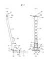
以下、本発明の実施の形態を図面に基づいて詳細に説明する。手摺支柱支持具10は、図2〜図4に示されるように、梁鉄筋組立体30に装着される。梁鉄筋組立体30は、図2に示されるように、複数本の真っ直ぐな梁主筋31を有しており、図2においては、最下段の4本の梁主筋31(a)と、最上段の4本の梁主筋31(b)と、中間段の左右2本の梁主筋31(c)が示されている。最下段の梁主筋31には符号aがカッコ書きで示され、最上段の梁主筋31には符号bがカッコ書きで示され、中間段の梁主筋31には符号cがカッコ書きで示されている。最下段と最上段との間には、中間段を構成する梁主筋が複数段設けられているが、他の中間段の梁主筋31は省略されている。図5においては、中間段の梁主筋が省略されている。 Hereinafter, embodiments of the present invention will be described in detail with reference to the drawings. The
全ての梁主筋31は、横断面が四辺形の範囲内に配置されており、全ての梁主筋31により形成される四辺形の外側を覆うように、複数本の枠状のスターラップ筋32が図示しないワイヤ等により梁主筋31に結束される。 All the beam
図2および図5に示される梁鉄筋組立体30は、躯体支柱を構成する柱鉄筋組立体に取り付けられ、梁鉄筋組立体30には床スラブを構成するスラブ鉄筋組立体が取り付けられる。それぞれの鉄筋組立体には型枠が配置され、型枠内にはコンクリートが流し込まれてコンクリートと鉄筋組立体とからなる躯体構造物が構築される。梁鉄筋組立体30の外側に型枠を配置するときなどのように、梁鉄筋組立体30の上に作業者が乗って種々の作業を行う場合には、図2に示されるよう、梁鉄筋組立体30の上に手摺支柱支持具10が装着される。手摺支柱支持具10には、図1および図2に示されるように、手摺支柱33が取り付けられ、手摺支柱33は手摺支柱支持具10により支持される。 The beam
手摺支柱支持具10はほぼ四辺形のベースプレート11を有し、ベースプレート11は手摺支柱支持具10が梁鉄筋組立体30の上に装着されるときには、図2に示されるように、複数本のスターラップ筋32の上に配置される。ベースプレート11は、図2においては、4本のスターラップ筋32の上に配置されるように梁主筋31に沿う方向の長さ寸法を有し、梁鉄筋組立体30の幅寸法の約2分の1程度の幅寸法を有している。ベースプレート11は、図2および図4に示されるように、梁鉄筋組立体30の一方側に寄せて配置され、配置された状態のもとでは、ベースプレート11の一辺は梁鉄筋組立体30の側辺よりも外方に迫り出している。 The
ベースプレート11には支持部材としての管状の部材つまりサヤ管12が取り付けられており、サヤ管12はベースプレート11の迫り出し辺に向けてずれている。スターラップ筋32の下側に配置される複数本の最上段の梁主筋31を横切る方向に延びて突き当てプレート13がベースプレート11に沿って配置されて、最上段の梁主筋31の下面に突き当てられる。 A tubular member as a support member, that is, a
図3に示されるように、ベースプレート11には、その長さ方向中央部であって迫り出し辺側に寄せられた位置に取付孔14aが設けられ、サヤ管12を介して取付孔14aの反対側には2つの取付孔14b、14cが設けられている。これらの3つの取付孔14a〜14cは、サヤ管12の中心を径方向に延びる径方向線の位置に設けられている。突き当てプレート13には、3つの取付孔14a〜14cに対応させて、3つの貫通孔15a〜15cが設けられている。それぞれの貫通孔15a〜15cに対応させて、図4に示されるように、突き当てプレート13の下面にはそれぞれナット16a〜16cが溶接されている。 As shown in FIG. 3, the
第1の取付孔としての取付孔14aに挿通される第1のボルト17aがナット16aにねじ結合され、第2の取付孔としての取付孔14cに挿通される第2のボルト17bがナット16cにねじ結合されている。それぞれのボルト17a、17bは、隣り合うスターラップ筋32の間の隙間を貫通している。このように、ボルトとナットからなる複数本のねじ部材により、ベースプレート11は突き当てプレート13に締結され、ベースプレート11と突き当てプレート13との間でスターラップ筋32と梁主筋31とが強く締め付けられる。突き当てプレート13は、図4に示されるように、梁鉄筋組立体30の幅寸法よりも長い寸法に設定されており、最上段の4本の梁主筋31に突き当てられる。なお、ボルトの本数は2本に限られることなく、3本以上のボルトを取り付けるようにしても良い。 The
図3および図4に示されるように、ベースプレート11は梁鉄筋組立体の一方側にずれており、他方側の上を作業者が走行することができる。ボルト17aは最上段の梁主筋31の外側を延びており、ボルト17bは最上段の4本の梁主筋31のうち中間の4本の間に延びている。最上段の梁主筋31等のように1段を構成する梁主筋31の本数は、梁鉄筋組立体30のサイズ等により多数種類がある。そのため、取付孔14cにボルト17bを取り付けると、ボルト17bに梁主筋31が干渉する場合がある。その場合には、予備的に設けられた他の取付孔14bにボルト17bが取り付けられ、ボルト17bはナット16bにねじ結合される。 As shown in FIGS. 3 and 4, the
このように、ベースプレート11は突き当てプレート13に2本のボルト17a、17bにより締結されるが、2本以上のボルトにより両方のプレートを締結するようにしても良い。 In this way, the
図1および図2に示される手摺支柱33は、支持部材としてのサヤ管12に挿入される支柱基部34と支柱基部34の内部に軸方向に移動自在に挿入される支柱先端部35とを備えている。支柱基部34はサヤ管12に設けられた止めねじ18によりサヤ管12に固定される。支柱先端部35には手摺取付具としてクランパ36が設けられており、クランパ36により支柱先端部35には手摺部材としての手摺単管37が装着される。手摺単管37の上下方向の位置を調整するために、支柱先端部35には軸方向に間隔を隔てて複数の位置調整孔38が設けられ、位置調整孔38を貫通して支柱基部34の先端面に当接する位置決めピン39が支柱基部34に設けられている。この明細書においては、手摺支柱支持具10が図2に示されるように、梁鉄筋組立体30に装着された状態を基準として、部材の上下関係が示されている。 The
次に、手摺支柱支持具10を用いて梁鉄筋組立体30に手摺部材としての手摺単管37を装着する手順について説明する。 Next, a procedure for mounting the handrail
図3および図4に示されるように、スターラップ筋32の上にベースプレート11を配置し、突き当てプレート13をベースプレート11に沿わせるようにして梁主筋31の下側に突き当てる。この状態のもとで、ボルト17aを取付孔14aに挿入してナット16aにねじ結合させ、ボルト17bを取付孔14cに挿入してナット16cにねじ結合させる。これにより、多数の隙間がある梁鉄筋組立体30に手摺支柱支持具10を締結することができる。 As shown in FIGS. 3 and 4, the
図5に示されるように、複数の手摺支柱支持具10を所定の間隔を隔てて梁鉄筋組立体30に取り付けるとともに、それぞれの手摺支柱支持具10に手摺支柱33を装着し、止めねじ18により手摺支柱33をサヤ管12に固定する。次いで、手摺支柱33の上端部に設けられたクランパ36に手摺単管37を取り付ける。これにより、図5に示されるように、手摺支柱支持具10に装着された手摺支柱33に手摺単管37が取り付けられる。手摺支柱33は図2に示されるように、梁鉄筋組立体30の幅方向一方側に配置されるので、作業者は幅方向他方側を走行することができる。 As shown in FIG. 5, a plurality of handrail strut supports 10 are attached to the beam reinforcing
手摺支柱33は、梁鉄筋組立体30に強固に締結された手摺支柱支持具10に取り付けられており、手摺単管37は確実に梁鉄筋組立体30に装着され、作業者は梁鉄筋組立体30の上で安全に作業を行うことができる。手摺単管37に代えて、手摺部材としては親綱を手摺支柱33の上端部に取り付けることもできる。 The
図6〜図8は他の実施の形態である手摺支柱支持具10を示している。これらの図においては、上述した手摺支柱支持具10と共通する部材には同一の符号が付されている。 6 to 8 show a
この手摺支柱支持具10においては、ベースプレート11には支持部材として支持台21が取り付けられている。支持台21は水平台板22とそれの両端部に一体となった脚部23とを備え、脚部23の下面がベースプレート11に固定されている。支持台21は、門形となっており、水平台板22の下側にはクランプ材収容空間24が設けられている。 In the
ベースプレート11には、上述したものと同様に、3つの取付孔14a〜14cが設けられており、2本のボルト17a、17bによりベースプレート11には突き当てプレート13が締結される。したがって、ベースプレート11とこれに締結される突き当てプレート13の構造は上述したものと同一であり、上述したベースプレート11には支持部材としてサヤ管12が取り付けられているのに対し、図7に示されるベースプレート11には支持台21が支持部材として取り付けられている。 The
支持台21には手摺支柱41が取り付けられる。手摺支柱41は横断面が四角形の柱部材からなり、上端部には手摺部材を支持する手摺取付具としてのフック42が設けられている。フック42は、図6および図8に示されるように、逆方向に開口部が設けられた2つのフック片42a、24bを有しており、2つのフック片42a、42bにより図6(A)に示されるように、円形の親綱ガイド孔43が形成される。手摺部材としての親綱44をそれぞれのフック片42a、42bにより形成される親綱ガイド孔43を通過させることにより、親綱44がフック42に引っ掛けられる。手摺支柱41の上端部には連結板45が設けられており、連結板45に設けられた係合孔46に親綱を連結するようにしても良い。 A
手摺支柱41の下端部には2枚の締結板51が取り付けられており、締結板51には支持台21のクランプ材収容空間24内に入り込んで水平台板22の内面に突き当てられるクランプ片52が設けられている。2枚の締結板51に連結された連結部材53には2つのナット54が取り付けられ、ボルト55がそれぞれのナット54にねじ結合されており、ボルト55とクランプ片52によりクランプ具が構成されている。ハンドル47が手摺支柱41に取り付けられており、作業者が手摺支柱41を持ち運ぶ際にハンドル47が使用される。したがって、手摺支柱41はクランプ具としてのボルト55を水平台板22に締め付けることにより、ボルト55とクランプ片52とにより支持台21に締結される。 Two
手摺支柱41が支持台21に取り付けられると、図6(A)に示されるように、手摺支柱41は上端部が梁鉄筋組立体30の側辺よりも外方に突出する方向に傾斜する。このように、手摺支柱41を傾斜させると、作業者は梁鉄筋組立体30の上を容易に走行することができる。 When the
いずれの形態の手摺支柱支持具10であっても、隙間がある骨組み構造の梁鉄筋組立体30に容易に取り付けることができ、鉄筋コンクリート製の躯体構造物の建築作業を円滑に行うことができる。 Any form of the
本発明は前記実施の形態に限定されるものではなく、その要旨を逸脱しない範囲で種々変更可能である。 The present invention is not limited to the above-described embodiment, and various modifications can be made without departing from the gist thereof.
10 手摺支柱支持具
11 ベースプレート
12 サヤ管(支持部材)
13 突き当てプレート
14a〜14c 取付孔
15a〜15c 貫通孔
16a〜16c ナット
17a、17b ボルト
21 支持台(支持部材)
22 水平台板
23 脚部
24 クランプ材収容空間
30 梁鉄筋組立体
31 梁主筋
32 スターラップ筋
33 手摺支柱
34 支柱基部
35 支柱先端部
36 クランパ(手摺取付具)
37 手摺単管(手摺部材)
41 手摺支柱
42 フック(手摺取付具)
44 親綱(手摺部材)
51 締結板
52 クランプ片
54 ナット
55 ボルト(クランプ具)10
13
22
37 Handrail single pipe (handrail member)
41
44 Main rope (handrail member)
51
Claims (6)
Translated fromJapanese複数本の前記スターラップ筋の上に配置されるベースプレートと、
前記ベースプレートに設けられ、前記手摺支柱を支持する手摺取付具が設けられた支持部材と、
前記スターラップ筋の下側に配置される複数本の梁主筋を横切る方向に前記ベースプレートに沿って配置されて前記梁主筋に突き当てられる突き当てプレートと、
隣り合う前記スターラップ筋の間の隙間を貫通し、前記ベースプレートと前記突き当てプレートとを締結する複数本のねじ部材と、を有し、
前記梁鉄筋組立体に隣り合って装着された手摺支柱支持具に支持される前記手摺支柱に手摺部材が取り付けられる、手摺支柱支持具。A handrail strut support tool that is attached to a beam reinforcing bar assembly consisting of a plurality of beam main bars and a plurality of frame-shaped stirrup bars bound to the beam main bars to support the handrail strut.
A base plate placed on the plurality of stirrup muscles and
A support member provided on the base plate and provided with a handrail attachment for supporting the handrail support, and a support member.
An abutting plate arranged along the base plate in a direction crossing a plurality of beam main bars arranged under the stirrup bar and abutted against the beam main bar,
It has a plurality of screw members that penetrate the gap between the adjacent stirrup bars and fasten the base plate and the abutting plate.
A handrail strut support to which a handrail member is attached to the handrail strut supported by a handrail strut support mounted adjacent to the beam reinforcing bar assembly.
前記手摺支柱は、支柱基部と当該支柱基部の内部に軸方向に移動自在に挿入されて前記手摺部材が装着される支柱先端部とを備え、
前記支持部材は前記支柱基部が挿入されるサヤ管である、手摺支柱支持具。In the handrail strut support according to claim 1,
The handrail strut includes a strut base and a strut tip portion that is axially movably inserted into the strut base and to which the handrail member is mounted.
The support member is a handrail support tool, which is a sheath pipe into which the support base is inserted.
前記手摺支柱は、上端部に手摺部材を支持する手摺取付具が設けられ、下端部に前記支持部材に締結されるクランプ具が設けられ、
前記支持部材は前記クランプ具が締結される支持台である、手摺支柱支持具。In the handrail strut support according to claim 1,
The handrail strut is provided with a handrail attachment for supporting the handrail member at the upper end portion, and a clamp tool for being fastened to the support member at the lower end portion.
The support member is a handrail support tool which is a support base on which the clamp tool is fastened.
前記手摺部材は手摺単管または親綱である、手摺支柱支持具。In the handrail strut support according to any one of claims 1 to 3,
The handrail member is a handrail supporter, which is a single handrail tube or a main rope.
前記ねじ部材は、前記突き当てプレートに溶接されたナットと、前記ベースプレートに形成された取付孔に挿通されて前記ナットにねじ結合されるボルトである、手摺支柱支持具。In the handrail strut support according to any one of claims 1 to 4.
The screw member is a handrail strut support which is a nut welded to the abutt plate and a bolt which is inserted into a mounting hole formed in the base plate and screwed to the nut.
前記ベースプレートに前記支持部材に対して一方側に形成された第1の取付孔に挿通される第1のボルトと、前記支持部材に対して反対側に位置させて前記ベースプレートに形成された第2の取付孔に挿通される第2のボルトと、を有する手摺支柱支持具。In the handrail strut support according to claim 5,
A first bolt inserted into the first mounting hole formed on one side of the support member on the base plate, and a second bolt formed on the base plate located on the opposite side of the support member. A handrail strut support having a second bolt inserted into the mounting hole of the.
Priority Applications (1)
| Application Number | Priority Date | Filing Date | Title |
|---|---|---|---|
| JP2019085121AJP2020180508A (en) | 2019-04-26 | 2019-04-26 | Handrail support column support tool |
Applications Claiming Priority (1)
| Application Number | Priority Date | Filing Date | Title |
|---|---|---|---|
| JP2019085121AJP2020180508A (en) | 2019-04-26 | 2019-04-26 | Handrail support column support tool |
Publications (1)
| Publication Number | Publication Date |
|---|---|
| JP2020180508Atrue JP2020180508A (en) | 2020-11-05 |
Family
ID=73023785
Family Applications (1)
| Application Number | Title | Priority Date | Filing Date |
|---|---|---|---|
| JP2019085121APendingJP2020180508A (en) | 2019-04-26 | 2019-04-26 | Handrail support column support tool |
Country Status (1)
| Country | Link |
|---|---|
| JP (1) | JP2020180508A (en) |
Cited By (3)
| Publication number | Priority date | Publication date | Assignee | Title |
|---|---|---|---|---|
| JP2022056534A (en)* | 2020-09-30 | 2022-04-11 | 有限会社山哲 | Fall prevention device and fall prevention method |
| JP2022186685A (en)* | 2021-06-03 | 2022-12-15 | 日鉄エンジニアリング株式会社 | Foundation structure, design method of foundation structure, program and one-story building |
| JP7558599B1 (en) | 2024-02-16 | 2024-10-01 | 株式会社サンポール | Grid structure, foundation structure device, and method for installing supports |
Citations (5)
| Publication number | Priority date | Publication date | Assignee | Title |
|---|---|---|---|---|
| JPS57117108U (en)* | 1981-01-12 | 1982-07-20 | ||
| JPH0671773U (en)* | 1993-03-11 | 1994-10-07 | 株式会社大輪通商 | Parent rope support |
| US5730245A (en)* | 1996-04-02 | 1998-03-24 | Conway; John | Safety cable deck anchor |
| KR20120003077U (en)* | 2010-10-26 | 2012-05-04 | 김천호 | Reinforcing Bar Rail |
| JP2016130421A (en)* | 2015-01-14 | 2016-07-21 | あけみ 植田 | Bearing member for scaffold board, and bearing method for scaffold board using the same applied when casting foundation concrete |
- 2019
- 2019-04-26JPJP2019085121Apatent/JP2020180508A/enactivePending
Patent Citations (5)
| Publication number | Priority date | Publication date | Assignee | Title |
|---|---|---|---|---|
| JPS57117108U (en)* | 1981-01-12 | 1982-07-20 | ||
| JPH0671773U (en)* | 1993-03-11 | 1994-10-07 | 株式会社大輪通商 | Parent rope support |
| US5730245A (en)* | 1996-04-02 | 1998-03-24 | Conway; John | Safety cable deck anchor |
| KR20120003077U (en)* | 2010-10-26 | 2012-05-04 | 김천호 | Reinforcing Bar Rail |
| JP2016130421A (en)* | 2015-01-14 | 2016-07-21 | あけみ 植田 | Bearing member for scaffold board, and bearing method for scaffold board using the same applied when casting foundation concrete |
Cited By (5)
| Publication number | Priority date | Publication date | Assignee | Title |
|---|---|---|---|---|
| JP2022056534A (en)* | 2020-09-30 | 2022-04-11 | 有限会社山哲 | Fall prevention device and fall prevention method |
| JP2022186685A (en)* | 2021-06-03 | 2022-12-15 | 日鉄エンジニアリング株式会社 | Foundation structure, design method of foundation structure, program and one-story building |
| JP7674311B2 (en) | 2021-06-03 | 2025-05-09 | 日鉄エンジニアリング株式会社 | Foundation structure, foundation structure design method, program, and single-story building |
| JP7558599B1 (en) | 2024-02-16 | 2024-10-01 | 株式会社サンポール | Grid structure, foundation structure device, and method for installing supports |
| JP2025125839A (en)* | 2024-02-16 | 2025-08-28 | 株式会社サンポール | Grid structure, foundation structure device, and support pillar installation method |
Similar Documents
| Publication | Publication Date | Title |
|---|---|---|
| JP2020180508A (en) | Handrail support column support tool | |
| KR101641340B1 (en) | Gang form cage having safety upper and lower worktable | |
| JP6872767B2 (en) | Support structure, support method and construction method of suspended scaffolding | |
| JP2018138717A (en) | Beam frame mounting structure and beam frame receiving member and beam frame passing member used therefor | |
| JP2017166312A (en) | Method for assembling formwork support device for tunnel lining concrete molding and leg connecting device for formwork support device | |
| KR102335856B1 (en) | Safety railing for steel beam installation | |
| JP4982534B2 (en) | Auxiliary tool for reinforcement work for deep foundation, and method for constructing reinforcement using this auxiliary tool | |
| KR20140040580A (en) | Safety belt rack device for construction | |
| KR20190041976A (en) | Coupling device for scaffolding pipes | |
| JP2020180507A (en) | Stanchion | |
| KR102370425B1 (en) | The safety rail of the formwork | |
| JP7208532B2 (en) | Prefabricated temporary staircase | |
| JP3904873B2 (en) | Handrail post and temporary handrail | |
| JP7313910B2 (en) | handrail device | |
| JP6001314B2 (en) | Parent rope support | |
| KR200497116Y1 (en) | Safety guard fixing device | |
| KR20170109973A (en) | Lower cage of gang form with supporting tool | |
| KR101875076B1 (en) | Steel framed reinforced concrete structure using existing steel structure | |
| JP6495846B2 (en) | Slope anchor construction method and rail unit set used therefor | |
| KR102529490B1 (en) | assembling devices of fence height adjustable of balustrade | |
| KR102437398B1 (en) | Easy-to-install integrated slab euroform system | |
| JP2019052461A (en) | Brace lower rail connection bracket | |
| JP5937333B2 (en) | Temporary passage | |
| JP2006144452A (en) | Master rope mounting bracket | |
| KR20220140306A (en) | Handrail for cable tray |
Legal Events
| Date | Code | Title | Description |
|---|---|---|---|
| A621 | Written request for application examination | Free format text:JAPANESE INTERMEDIATE CODE: A621 Effective date:20220113 | |
| A977 | Report on retrieval | Free format text:JAPANESE INTERMEDIATE CODE: A971007 Effective date:20221012 | |
| A131 | Notification of reasons for refusal | Free format text:JAPANESE INTERMEDIATE CODE: A131 Effective date:20221018 | |
| A02 | Decision of refusal | Free format text:JAPANESE INTERMEDIATE CODE: A02 Effective date:20230411 |