JP2020176873A - Calibration equipment, calibration method, spectroscopic camera, and display device - Google Patents
Calibration equipment, calibration method, spectroscopic camera, and display deviceDownload PDFInfo
- Publication number
- JP2020176873A JP2020176873AJP2019077970AJP2019077970AJP2020176873AJP 2020176873 AJP2020176873 AJP 2020176873AJP 2019077970 AJP2019077970 AJP 2019077970AJP 2019077970 AJP2019077970 AJP 2019077970AJP 2020176873 AJP2020176873 AJP 2020176873A
- Authority
- JP
- Japan
- Prior art keywords
- value
- correction
- unit
- image
- spectroscopic
- Prior art date
- Legal status (The legal status is an assumption and is not a legal conclusion. Google has not performed a legal analysis and makes no representation as to the accuracy of the status listed.)
- Granted
Links
- 238000000034methodMethods0.000titleclaimsabstractdescription43
- 238000012937correctionMethods0.000claimsabstractdescription233
- 239000011159matrix materialSubstances0.000claimsabstractdescription159
- 238000005259measurementMethods0.000claimsabstractdescription136
- 238000010606normalizationMethods0.000claimsabstractdescription41
- 230000003595spectral effectEffects0.000claimsabstractdescription37
- 238000004364calculation methodMethods0.000claimsabstractdescription29
- 238000012545processingMethods0.000claimsabstractdescription23
- 238000000605extractionMethods0.000claimsabstractdescription22
- 239000000284extractSubstances0.000claimsabstractdescription10
- 238000011156evaluationMethods0.000claimsdescription73
- 239000003086colorantSubstances0.000claimsdescription22
- 238000003702image correctionMethods0.000claimsdescription17
- 238000012549trainingMethods0.000claimsdescription13
- 230000008859changeEffects0.000claimsdescription4
- 230000001915proofreading effectEffects0.000claims1
- 238000006243chemical reactionMethods0.000abstractdescription16
- 238000010586diagramMethods0.000abstractdescription8
- 238000004891communicationMethods0.000description26
- 230000008569processEffects0.000description23
- 238000003384imaging methodMethods0.000description22
- 238000012986modificationMethods0.000description13
- 230000004048modificationEffects0.000description13
- 230000003287optical effectEffects0.000description12
- 230000006870functionEffects0.000description11
- 239000000758substrateSubstances0.000description7
- 238000012360testing methodMethods0.000description6
- 230000006872improvementEffects0.000description5
- 239000004973liquid crystal related substanceSubstances0.000description5
- 230000000694effectsEffects0.000description3
- 230000009471actionEffects0.000description2
- BJQHLKABXJIVAM-UHFFFAOYSA-Nbis(2-ethylhexyl) phthalateChemical compoundCCCCC(CC)COC(=O)C1=CC=CC=C1C(=O)OCC(CC)CCCCBJQHLKABXJIVAM-UHFFFAOYSA-N0.000description2
- 229910052736halogenInorganic materials0.000description2
- 150000002367halogensChemical class0.000description2
- 238000005286illuminationMethods0.000description2
- 238000000926separation methodMethods0.000description2
- 238000002834transmittanceMethods0.000description2
- 238000004458analytical methodMethods0.000description1
- 230000005540biological transmissionEffects0.000description1
- 230000000903blocking effectEffects0.000description1
- 238000010276constructionMethods0.000description1
- 230000001678irradiating effectEffects0.000description1
- 238000010238partial least squares regressionMethods0.000description1
- 230000029553photosynthesisEffects0.000description1
- 238000010672photosynthesisMethods0.000description1
- 230000000243photosynthetic effectEffects0.000description1
- 238000012628principal component regressionMethods0.000description1
- 238000000985reflectance spectrumMethods0.000description1
- 238000002798spectrophotometry methodMethods0.000description1
- 238000001228spectrumMethods0.000description1
Images


Classifications
- G—PHYSICS
- G01—MEASURING; TESTING
- G01J—MEASUREMENT OF INTENSITY, VELOCITY, SPECTRAL CONTENT, POLARISATION, PHASE OR PULSE CHARACTERISTICS OF INFRARED, VISIBLE OR ULTRAVIOLET LIGHT; COLORIMETRY; RADIATION PYROMETRY
- G01J3/00—Spectrometry; Spectrophotometry; Monochromators; Measuring colours
- G01J3/02—Details
- G01J3/0297—Constructional arrangements for removing other types of optical noise or for performing calibration
- G—PHYSICS
- G01—MEASURING; TESTING
- G01J—MEASUREMENT OF INTENSITY, VELOCITY, SPECTRAL CONTENT, POLARISATION, PHASE OR PULSE CHARACTERISTICS OF INFRARED, VISIBLE OR ULTRAVIOLET LIGHT; COLORIMETRY; RADIATION PYROMETRY
- G01J3/00—Spectrometry; Spectrophotometry; Monochromators; Measuring colours
- G01J3/12—Generating the spectrum; Monochromators
- G01J3/26—Generating the spectrum; Monochromators using multiple reflection, e.g. Fabry-Perot interferometer, variable interference filters
- G—PHYSICS
- G01—MEASURING; TESTING
- G01J—MEASUREMENT OF INTENSITY, VELOCITY, SPECTRAL CONTENT, POLARISATION, PHASE OR PULSE CHARACTERISTICS OF INFRARED, VISIBLE OR ULTRAVIOLET LIGHT; COLORIMETRY; RADIATION PYROMETRY
- G01J3/00—Spectrometry; Spectrophotometry; Monochromators; Measuring colours
- G01J3/02—Details
- G01J3/0205—Optical elements not provided otherwise, e.g. optical manifolds, diffusers, windows
- G01J3/0254—Spectrometers, other than colorimeters, making use of an integrating sphere
- G—PHYSICS
- G01—MEASURING; TESTING
- G01J—MEASUREMENT OF INTENSITY, VELOCITY, SPECTRAL CONTENT, POLARISATION, PHASE OR PULSE CHARACTERISTICS OF INFRARED, VISIBLE OR ULTRAVIOLET LIGHT; COLORIMETRY; RADIATION PYROMETRY
- G01J3/00—Spectrometry; Spectrophotometry; Monochromators; Measuring colours
- G01J3/28—Investigating the spectrum
- G01J3/2823—Imaging spectrometer
- G—PHYSICS
- G01—MEASURING; TESTING
- G01J—MEASUREMENT OF INTENSITY, VELOCITY, SPECTRAL CONTENT, POLARISATION, PHASE OR PULSE CHARACTERISTICS OF INFRARED, VISIBLE OR ULTRAVIOLET LIGHT; COLORIMETRY; RADIATION PYROMETRY
- G01J3/00—Spectrometry; Spectrophotometry; Monochromators; Measuring colours
- G01J3/28—Investigating the spectrum
- G01J3/30—Measuring the intensity of spectral lines directly on the spectrum itself
- G—PHYSICS
- G01—MEASURING; TESTING
- G01J—MEASUREMENT OF INTENSITY, VELOCITY, SPECTRAL CONTENT, POLARISATION, PHASE OR PULSE CHARACTERISTICS OF INFRARED, VISIBLE OR ULTRAVIOLET LIGHT; COLORIMETRY; RADIATION PYROMETRY
- G01J3/00—Spectrometry; Spectrophotometry; Monochromators; Measuring colours
- G01J3/46—Measurement of colour; Colour measuring devices, e.g. colorimeters
- G01J3/50—Measurement of colour; Colour measuring devices, e.g. colorimeters using electric radiation detectors
- G—PHYSICS
- G01—MEASURING; TESTING
- G01J—MEASUREMENT OF INTENSITY, VELOCITY, SPECTRAL CONTENT, POLARISATION, PHASE OR PULSE CHARACTERISTICS OF INFRARED, VISIBLE OR ULTRAVIOLET LIGHT; COLORIMETRY; RADIATION PYROMETRY
- G01J3/00—Spectrometry; Spectrophotometry; Monochromators; Measuring colours
- G01J3/46—Measurement of colour; Colour measuring devices, e.g. colorimeters
- G01J3/52—Measurement of colour; Colour measuring devices, e.g. colorimeters using colour charts
- G01J3/524—Calibration of colorimeters
Landscapes
- Physics & Mathematics (AREA)
- Spectroscopy & Molecular Physics (AREA)
- General Physics & Mathematics (AREA)
- Spectrometry And Color Measurement (AREA)
- Camera Bodies And Camera Details Or Accessories (AREA)
Abstract
Translated fromJapaneseDescription
Translated fromJapanese本発明は、校正装置、校正方法、分光カメラ、及び表示装置に関する。 The present invention relates to a calibration device, a calibration method, a spectroscopic camera, and a display device.
従来、分光カメラで撮像される分光画像の波長むらを補正するための補正行列を算出する校正装置が知られている(例えば、特許文献1参照)。
特許文献1に記載の装置では、光源から出射され、白色基準板で反射させた光を分光カメラで撮像して、各波長に対する白色基準データを取得する。また、分光カメラへの光の入射を遮断してダーク値を取得する。さらに、光源から出射され、反射率が既知の基準板で反射させた光を分光カメラで撮像して、各波長に対する各画素の測定値を取得する。基準板は複数色用意し、これらの複数色の基準板に対する分光画像をそれぞれ取得する。
そして、測定値からダーク値を減算した値を、白色基準データからダーク値を減算した値で除算して反射率を算出し、これらの反射率と既知の反射率とを用いて、波長むらを補正するための補正行列を算出する。これにより、光源の照明むらやシェーディングの影響を抑制した補正行列の算出が可能となる。Conventionally, a calibration device for calculating a correction matrix for correcting wavelength unevenness of a spectroscopic image captured by a spectroscopic camera is known (see, for example, Patent Document 1).
In the apparatus described in
Then, the value obtained by subtracting the dark value from the measured value is divided by the value obtained by subtracting the dark value from the white reference data to calculate the reflectance, and the wavelength unevenness is calculated by using these reflectances and the known reflectances. Calculate the correction matrix for correction. This makes it possible to calculate a correction matrix that suppresses the effects of uneven illumination of the light source and shading.
しかしながら、特許文献1の校正装置及び校正方法では、光源の光量を一定とし、各波長の反射率から最小二乗法を用いて補正行列の各行列要素を算出しているので、変換誤差が光源の明るさに依らず同程度発生してしまう。この場合、測定対象が暗色である場合に、色変換後の色度が悪化する傾向がある、との課題がある。 However, in the calibration device and calibration method of
第一適用例に係る校正装置は、光源部からの均一光を分光カメラで撮像した際の撮像画像である分光画像を取得する測定値取得部と、前記均一光を校正基準器で測定した際の測定結果である分光基準値を取得する基準値取得部と、前記分光画像のうち、補正行列を生成する画素である補正点の階調値を測定値として抽出する階調値抽出部と、前記補正点の前記測定値、及び前記分光基準値を、前記光源部から出射される前記均一光の輝度値で除算して、正規化測定値、及び正規化基準値を得る正規化処理部と、前記正規化測定値及び前記正規化基準値に基づいて、前記補正行列を算出する行列算出部と、を備える。 The calibrator according to the first application example includes a measurement value acquisition unit that acquires a spectral image that is an image captured when uniform light from a light source unit is captured by a spectroscopic camera, and a measurement value acquisition unit that acquires the uniform light with a calibration reference device. A reference value acquisition unit that acquires the spectral reference value that is the measurement result of the above, and a gradation value extraction unit that extracts the gradation value of the correction point, which is a pixel that generates the correction matrix, as a measurement value in the spectral image. A normalization processing unit that obtains a normalized measurement value and a normalized reference value by dividing the measured value of the correction point and the spectral reference value by the brightness value of the uniform light emitted from the light source unit. A matrix calculation unit that calculates the correction matrix based on the normalized measurement value and the normalized reference value.
第一適用例の校正装置において、前記光源部は、画像光を出力する表示装置と、前記画像光の光を均一化する積分球とを含むことが好ましい。 In the calibration device of the first application example, the light source unit preferably includes a display device that outputs image light and an integrating sphere that homogenizes the light of the image light.
第一適用例の校正装置において、前記光源部は、前記表示装置から黒色と、複数の低階調色を含む複数の単一色の前記画像光を出力させ、前記正規化処理部は、黒色以外の単一色の前記画像光に対する前記補正点の前記測定値から、黒色の前記画像光に対する前記補正点の前記測定値を差し引いた値を、前記画像光の前記輝度値で除算して前記正規化測定値とし、黒色以外の単一色の前記画像光に対する前記分光基準値から、黒色の前記画像光に対する前記分光基準値を差し引いた値を、前記画像光の前記輝度値で除算して前記正規化基準値とし、黒色及び複数の低階調色の前記画像光に対する前記補正点の前記測定値を、前記画像光の前記輝度値で除算して黒色正規化測定値とし、黒色及び低階調色の前記画像光に対する前記分光基準値を、前記画像光の前記輝度値で除算して黒色正規化基準値とし、前記行列算出部は、前記正規化測定値及び前記正規化基準値に基づいて、通常補正行列を算出し、前記黒色正規化測定値及び前記黒色正規化基準値に基づいて、黒色補正行列を算出することが好ましい。 In the calibration device of the first application example, the light source unit outputs black and the image light of a plurality of single colors including a plurality of low gradation colors from the display device, and the normalization processing unit is other than black. The value obtained by subtracting the measured value of the correction point for the black image light from the measured value of the correction point for the single color image light is divided by the brightness value of the image light for the normalization. As the measured value, the value obtained by subtracting the spectral reference value for the black image light from the spectral reference value for the image light of a single color other than black is divided by the brightness value of the image light for the normalization. As a reference value, the measured value of the correction point for the image light of black and a plurality of low gradation colors is divided by the brightness value of the image light to obtain a black normalized measurement value, and the black and low gradation colors are used. The spectral reference value for the image light is divided by the brightness value of the image light to obtain a black normalization reference value, and the matrix calculation unit is based on the normalization measurement value and the normalization reference value. It is preferable to calculate the normal correction matrix and calculate the black correction matrix based on the black normalization measurement value and the black normalization reference value.
第一適用例の校正装置において、前記分光画像の前記階調値を前記分光カメラで前記均一光を測定した際の露光時間で除算して露光補正する露光補正部を備えることが好ましい。 It is preferable that the calibration apparatus of the first application example includes an exposure compensation unit that divides the gradation value of the spectroscopic image by the exposure time when the uniform light is measured by the spectroscopic camera to correct the exposure.
第一適用例の校正装置において、前記行列算出部により算出された前記補正行列の補正精度を評価する精度評価部を備えることが好ましい。 The calibration device of the first application example preferably includes an accuracy evaluation unit for evaluating the correction accuracy of the correction matrix calculated by the matrix calculation unit.
第一適用例の校正装置において、前記階調値抽出部は、前記補正点の位置、前記補正点の個数、前記補正点に対する前記測定値を抽出する対象波長、及び前記対象波長の数の少なくともいずれかを変更した複数の学習データを生成し、前記行列算出部は、複数の前記学習データのそれぞれに対して前記補正行列を算出し、前記精度評価部は、各前記学習データに対する前記補正行列をそれぞれ評価して、最も高評価である前記補正行列を採用することが好ましい。 In the calibration device of the first application example, the gradation value extraction unit is at least the position of the correction point, the number of the correction points, the target wavelength for extracting the measured value with respect to the correction point, and the number of the target wavelengths. A plurality of training data in which any of them is changed are generated, the matrix calculation unit calculates the correction matrix for each of the plurality of training data, and the accuracy evaluation unit calculates the correction matrix for each of the training data. It is preferable to evaluate each of the above and adopt the correction matrix having the highest evaluation.
第一適用例の校正装置において、前記階調値抽出部は、前記精度評価部により最も高評価と評価された前記補正行列に対応する前記学習データの、前記補正点の位置、前記補正点の個数、前記対象波長、及び前記対象波長の数の少なくともいずれかを変更して、新たな学習データを生成し、前記精度評価部は、前記新たな学習データに基づく前記補正行列と、前回の前記学習データに基づく前記補正行列との評価の差が所定の閾値以下である場合に、前記新たな学習データに基づく前記補正行列を採用することが好ましい。 In the calibration device of the first application example, the gradation value extraction unit determines the position of the correction point and the correction point of the training data corresponding to the correction matrix evaluated as the highest evaluation by the accuracy evaluation unit. At least one of the number, the target wavelength, and the number of the target wavelengths is changed to generate new training data, and the accuracy evaluation unit uses the correction matrix based on the new learning data and the previous correction matrix. When the difference in evaluation from the correction matrix based on the training data is equal to or less than a predetermined threshold value, it is preferable to adopt the correction matrix based on the new learning data.
第二適用例に係る校正方法は、分光カメラで撮像される分光画像を補正する補正行列を算出する校正装置の校正方法であって、光源部からの均一光を前記分光カメラで撮像して前記分光画像を取得するステップと、前記均一光を校正基準器で測定した際の測定結果である分光基準値を取得するステップと、前記分光画像のうち、前記補正行列を生成する画素である補正点の階調値を測定値として抽出するステップと、前記補正点の前記測定値、及び前記分光基準値を、前記光源部から出射される前記均一光の輝度値で除算して、正規化測定値、及び正規化基準値を得るステップと、前記正規化測定値及び前記正規化基準値に基づいて、前記補正行列を算出するステップと、を実施する。 The calibration method according to the second application example is a calibration method of a calibration device that calculates a correction matrix that corrects a spectral image captured by a spectroscopic camera, and the uniform light from a light source unit is imaged by the spectroscopic camera to obtain the above-mentioned. A step of acquiring a spectroscopic image, a step of acquiring a spectroscopic reference value which is a measurement result when the uniform light is measured by a calibration reference device, and a correction point which is a pixel of the spectroscopic image that generates the correction matrix. The step of extracting the gradation value of the above as a measurement value, the measurement value of the correction point, and the spectral reference value are divided by the brightness value of the uniform light emitted from the light source unit to obtain a normalized measurement value. , And a step of obtaining the normalization reference value, and a step of calculating the correction matrix based on the normalization measurement value and the normalization reference value.
第三適用例に係る分光カメラは、第一適用例の校正装置により算出された前記補正行列が記録される記録部と、前記補正行列を用いて前記分光画像の所定位置の色を補正する色補正部と、を備える。 The spectroscopic camera according to the third application example has a recording unit in which the correction matrix calculated by the calibration apparatus of the first application example is recorded, and a color that corrects the color at a predetermined position of the spectroscopic image by using the correction matrix. It is provided with a correction unit.
第三適用例の分光カメラにおいて、表示装置から測定点の座標を取得し、複数の前記補正点に対する前記補正行列から、前記測定点に対する前記補正行列を内挿補間する補間部を備えることが好ましい。 It is preferable that the spectroscopic camera of the third application example includes an interpolation unit that acquires the coordinates of the measurement points from the display device and interpolates the correction matrix for the measurement points from the correction matrices for the plurality of correction points. ..
第四適用例に係る表示装置は、第三適用例の分光カメラと通信可能に接続され、画像光を出力する表示装置であって、前記分光カメラに、前記分光画像の所定の測定点の位置を送信して、測色の実施を指令する測色指令部と、前記分光カメラから、前記測定点に対する測色結果を受信し、前記測色結果に基づいて、前記画像光を補正する画像補正部と、を備える。 The display device according to the fourth application example is a display device communicatively connected to the spectroscopic camera of the third application example and outputs image light, and the position of a predetermined measurement point of the spectroscopic image on the spectroscopic camera. Is transmitted to receive a color measurement result for the measurement point from the color measurement command unit that commands the execution of color measurement and the spectroscopic camera, and image correction that corrects the image light based on the color measurement result. It has a part and.
[第一実施形態]
以下、第一実施形態について説明する。
図1は、第一実施形態の校正システム1の概略構成を示す図である。図2は、校正システム1のブロック図である。
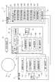
図1及び図2に示すように、校正システム1は、光源部10と、校正基準器である分光光度計20と、校正対象である分光カメラ30と、校正装置40とを備えている。[First Embodiment]
Hereinafter, the first embodiment will be described.
FIG. 1 is a diagram showing a schematic configuration of the
As shown in FIGS. 1 and 2, the
[光源部10の構成]
光源部10は、表示装置11と、積分球12と、を備える。
表示装置11は、画像光を出力する装置である。この表示装置11は、例えばプロジェクターにより構成されている。
表示装置11は、図2に示すように、画像光生成部111、通信部112、メモリー113、及びプロセッサー114を備えて構成されている。
なお、以降の説明にあたり、表示装置11の通信部112、分光カメラ30の通信部34、校正装置40の通信部41を区別するため、表示装置11の通信部112を第一通信部112と称する。また、分光カメラ30の通信部34を第二通信部34と称し、校正装置40の通信部41を第三通信部41と称する。
また、表示装置11のメモリー113、分光カメラ30のメモリー35、校正装置40のメモリー42を区別するため、表示装置11のメモリー113を第一メモリー113と称する。また、分光カメラ30のメモリー35を第二メモリー35と称し、校正装置40のメモリー42を第三メモリー42と称する。
さらに、表示装置11のプロセッサー114、分光カメラ30のプロセッサー36、校正装置40のプロセッサー43を区別するため、表示装置11のプロセッサー114を第一プロセッサー114と称する。また、分光カメラ30のプロセッサー36を第二プロセッサー36と称し、校正装置40のプロセッサー43を第三プロセッサー43と称する。[Structure of light source unit 10]
The
The
As shown in FIG. 2, the
In the following description, in order to distinguish the
Further, in order to distinguish the
Further, in order to distinguish the
画像光生成部111は、例えば、光源、光分離素子、液晶パネル、光合成素子、及び投射光学系等を備えて構成されている。
光源は、ハロゲンランプ等により構成されており、画像光を生成するための光を出力する。
光分離素子は、光源から出力された光をR(赤色)、G(緑色)、B(青色)の光に分離する。
液晶パネルは、R,G,Bの各色の光路上にそれぞれ設けられる。この液晶パネルは、複数の画素を有し、画素毎に光の透過率を変更可能な光学素子であり、第一プロセッサー114の制御に基づいて、各画素の光の透過率を変更する。
光合成素子は、液晶パネルを透過した各色の光を合成して、画像光を形成する。
投射光学系は、投射レンズ等を含んで構成され、画像光を外部に出射させる。The image
The light source is composed of a halogen lamp or the like, and outputs light for generating image light.
The light separation element separates the light output from the light source into R (red), G (green), and B (blue) light.
The liquid crystal panel is provided on the optical path of each color of R, G, and B, respectively. This liquid crystal panel is an optical element having a plurality of pixels and capable of changing the light transmittance for each pixel, and changes the light transmittance of each pixel based on the control of the
The photosynthetic element synthesizes light of each color transmitted through the liquid crystal panel to form image light.
The projection optical system is configured to include a projection lens and the like, and emits image light to the outside.
第一通信部112は、分光カメラ30、及び校正装置40等の外部機器と通信可能する。第一通信部112による通信方式は特に限定されず、例えば有線により外部機器に接続されていてもよく、無線通信により外部機器と通信してもよい。 The
第一メモリー113は、表示装置11を制御する各種プログラムや各種情報を記録する。各種情報としては、校正システム1において、分光カメラ30の校正処理を実施する際に出力する基準画像、外部機器から入力される画像情報に対する光源や液晶パネルの駆動パラメーター等が記録されている。 The
第一プロセッサー114は、第一メモリー113に記憶された各種プログラムを読み込み実行することで、出力制御部114A、測色指令部114B、画像補正部114Cなどとして機能する。 The
出力制御部114Aは、画像光生成部111を制御し、外部機器から入力される画像情報やメモリーに記憶された基準画像に対応する画像光を生成させる。この際、出力制御部114Aは、メモリーに記憶される駆動パラメーターに従って、画像光を生成する。 The
測色指令部114Bは、画像光生成部111から画像光が投射対象に投射された際に、分光カメラ30に分光画像の撮像指令と、測定点の位置とを送信する。これにより、分光カメラ30により、投射対象の投射された画像光が撮像され、かつ、分光カメラにおいて、測定点に対する色変換処理が実施される。そして、測色指令部114Bは、分光カメラから、色変換処理された各測定点に対する測色結果を受信する。 When the image light is projected onto the projection target from the image
画像補正部114Cは、分光カメラ30から測定点に対する測色結果を受信し、受信した測色結果に基づいて、画像光生成部111を駆動させるための駆動パラメーターを補正する。 The
積分球12は、内面に、球状の反射面を有する光学部材であり、入射窓121、第一出射窓122、及び第二出射窓123を有する。入射窓121には、表示装置11が接続されており、表示装置11から出力された光を入射される。第一出射窓122には、分光光度計20が接続され、第二出射窓123には、分光カメラ30が接続されている。
積分球12は、表示装置11から入射された画像光を反射面で反射させることで混合して、面内で光量が均一になる。均一化された画像光は、第一出射窓122から分光光度計20に出射され、第二出射窓123から分光カメラ30に出射される。The integrating
The integrating
[分光光度計20の構成]
分光光度計20は、積分球12から出力された画像光を受光し、画像光の分光測定を実施する。この分光光度計20は、校正基準器であり、入射光の正確な分光測定を行う装置である。
本実施形態では、分光光度計20は、分光測定結果として、入射光の三刺激値を出力する。[Structure of spectrophotometer 20]
The
In the present embodiment, the
[分光カメラ30の構成]
分光カメラ30は、校正システム1で校正対象となる分光器であり、積分球12から出力された画像光を受光して、複数の波長に対する分光画像を撮像する。
分光カメラ30は、図2に示すように、入射光学系31、分光フィルター32、撮像部33、第二通信部34、第二メモリー35、及び第二プロセッサー36を備える。
入射光学系31は、画像光が入射される複数のレンズを備えて構成され、入射した画像光を分光フィルター32及び撮像部33に導く。[Structure of spectroscopic camera 30]
The
As shown in FIG. 2, the
The incident
分光フィルター32は、入射した画像光から所定波長の光を透過させる分光素子である。
図3は、分光フィルター32の一例を示す図である。
本実施形態では、分光フィルター32として、第一基板321と、第二基板322と、第一基板321に設けられる第一反射膜323と、第二基板322に設けられる第二反射膜324と、ギャップ変更部325とを備える、波長可変型のファブリーペローエタロンを用いる。
この分光フィルター32では、第一反射膜323と第二反射膜324とがギャップを介して対向しており、ギャップの寸法に応じた波長の光が分光フィルター32を透過する。
第二基板322は、第二反射膜324が設けられる可動部332Aと、可動部322Aを保持して、第一基板321に対して進退させる保持部322Bとを備える。
また、ギャップ変更部325は、例えば静電アクチュエーター等により構成されており、可動部322Aを第一基板321側に変位させることで、第一反射膜323と第二反射膜324との間のギャップの寸法を変更する。これにより、分光フィルター32を透過する光の波長も変化する。The
FIG. 3 is a diagram showing an example of the
In the present embodiment, as the
In this
The
Further, the
撮像部33は、複数の撮像画素を有し、分光フィルター32の第一反射膜323及び第二反射膜324を透過した光を受光して、分光画像を撮像する。 The
第二通信部34は、表示装置11や校正装置40等の外部機器と通信する。第二通信部34の通信方式は特に限定されず、有線接続されていてもよく、無線通信接続であってもよい。 The
第二メモリー35は、分光カメラ30を制御する各種情報を記憶する記録部である。具体的には、第二メモリー35は、校正装置40により生成された補正行列、分光フィルター32を駆動させる駆動テーブル等を記録する。また、第二メモリー35には、分光カメラ30を制御する各種プログラムが記録されている。なお、補正行列についての詳細な説明は後述する。 The
第二プロセッサー36は、第二メモリー35に記憶されたプログラムを読み込み実行することで、撮像制御部361、補間部362、色補正部363として機能する。
撮像制御部361は、駆動テーブルに基づいて分光フィルター32を制御し、分光フィルター32を透過する光の波長を切り替える。また、撮像部33の露光制御を行って、分光画像を撮像させる。The
The image
補間部362は、表示装置11から分光画像における測定点が指定された際に、第二メモリー35に記憶された所定の補正点を用いて、測定点に対する補正行列を内挿補間により算出する。
色補正部363は、補正行列を用いて、分光画像の所定位置の色を補正する。具体的には、色補正部363は、分光画像の所定位置に対する測定値を補正して三刺激値に色変換する。When the measurement point in the spectroscopic image is designated by the
The
なお、本実施形態の分光カメラ30は、表示装置11であるプロジェクターの色補正を実施する際に用いられる。
より具体的には、分光カメラ30は、表示装置11から投射対象に投射された画像を撮像し、複数の波長に対する分光画像を取得する。また、分光カメラ30は、測色の対象となる測定点を表示装置11から受信し、校正システム1により設定された補正行列を用いて、分光画像における測定点に対する三刺激値を算出して、表示装置11に送信する。これにより、表示装置11は、測定点に対する三刺激値に基づいて、駆動パラメーターを更新して色補正を行うことが可能となる。The
More specifically, the
[校正装置40の構成]
校正装置40は、図2に示すように、第三通信部41、第三メモリー42、第三プロセッサー43等を含んで構成されている。
第三通信部41は、表示装置11、分光光度計20、及び分光カメラ30に接続されており、これらの表示装置11、分光光度計20、及び分光カメラ30と通信する。
第三メモリー42は、校正装置40を制御する各種プログラムを記憶する。
第三プロセッサー43は、第三メモリー42に記録されたプログラムを読み込み実行することで、光出力指令部431、測定値取得部432、基準値取得部433、露光補正部434、階調値抽出部435、正規化処理部436、及び行列算出部437として機能する。[Configuration of calibration device 40]
As shown in FIG. 2, the
The
The
The
光出力指令部431は、表示装置11に、複数の基準画像に対応する画像光の出力を指令する。基準画像は、例えば白色、赤色、緑色、青色、及び黒色の単一色画像であって、白色、赤色、緑色、及び青色に関しては、階調値がそれぞれ異なる7パターンの基準画像を用いる。この場合、29色の基準画像の画像光が表示装置11から順次出力される。 The optical
測定値取得部432は、分光カメラ30に対して、分光画像の撮像を指令する分光測定指令を送信し、分光カメラ30から分光画像を受信する。分光カメラ30は、分光測定指令を受信すると、分光フィルター32の透過波長を順次切り替えて、各波長に対する撮像画像である分光画像を撮像する。この際、1つの基準画像の画像光に対して複数の波長に対応する分光画像を取得する。つまり、表示装置11から出射される画像光の色が切り替えられる毎に、複数の波長の分光画像が撮像される。例えば、29色の基準画像に対して、16バンドの分光画像を取得する場合、29×16個の分光画像が得られる。 The measurement
基準値取得部433は、分光光度計20に対して、基準値測定指令を出力し、測定結果である分光基準値を取得する。本実施形態では、分光光度計20により測定される入射光の三刺激値が分光基準値となる。 The reference
露光補正部434は、分光画像の各画素の階調値を、分光カメラ30の撮像部33で画像光を撮像した際の露光時間で除算して補正する。
なお、本実施形態では、分光カメラ30は、撮像部33で画像光を撮像した際の露光時間を計測し、分光画像に関連付けて校正装置40に出力する。露光補正部434は、測定値取得部432により分光画像とともに受信した露光時間に基づいて、分光画像の各画素の階調値を補正する。The
In the present embodiment, the
階調値抽出部435は、分光画像の複数の画像のうちの補正点に対する測定値を抽出する。この補正点は、補正行列を生成する対象座標を示している。なお、補正点の数及び位置は、予め設定されており、第三メモリー42に記憶されている。
また、階調値抽出部435は、補正点の測定値の抽出に関し、ノイズの影響を抑制するため、補正点と、その周囲画素との階調値を取得し、これらの画素の階調値の平均を補正点に対する測定値とする。The gradation
Further, the gradation
正規化処理部436は、補正点に対する測定値、及び分光基準値を、表示装置11から出力される画像光の輝度値を用いて正規化する。
行列算出部437は、正規化された測定値、及び分光基準値を用いて、測定値を分光基準値に変換するための補正行列を算出する。なお、本実施形態の補正行列は、分光画像の補正点の階調値を、三刺激値に変換する色変換行列となる。The
The
[校正方法]
本実施形態の校正システム1は、校正対象である分光カメラ30の色補正を行う。
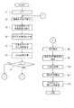
図4は、本実施形態の校正方法を示すフローチャートである。
分光カメラ30の校正処理、つまり、補正行列の生成処理では、まず、図1に示すように、表示装置11、分光光度計20、及び分光カメラ30を積分球12に接続し、校正装置40に校正処理の開始を指令する。
これにより、校正装置40は、まず、画像光の色を示すカラー変数cを初期化してc=1とする(ステップS1)。なお、カラー変数cの最大値はCmaxであり、表示装置11から、本実施形態では、白色、赤色、緑色、青色の階調値をそれぞれ7パターンで変化させた28色の基準画像と、黒色の基準画像を用いるので、Cmax=29である。カラー変数と、基準画像の色とは予め対応付けられている。
そして、光出力指令部431は、表示装置11に対してカラー変数cに対応する基準画像の画像光を出射させる旨の出力指令を送信する(ステップS2)。ステップS2により校正装置40から表示装置11に画像光の出力指令が入力されると、表示装置11の出力制御部114Aは、駆動パラメーターに基づいて画像光生成部111を制御し、カラー変数cに対応した色の画像光を生成して積分球12に出射する。[Calibration method]
The
FIG. 4 is a flowchart showing the calibration method of the present embodiment.
In the calibration process of the
As a result, the
Then, the light
また、校正装置40の基準値取得部433は、分光光度計20に対して基準値測定指令を出力する(ステップS3)。これにより、分光光度計20は、積分球12から出射される均一光の分光測定を実施して、分光基準値である三刺激値xCを出力する。分光基準値である三刺激値xCを、以降、基準三刺激値xCと称する。
基準値取得部433は、分光光度計20から基準三刺激値xCを受信すると(ステップS4)、第三メモリー42に記憶する。Further, the reference
When the reference
さらに、校正装置40の測定値取得部432は、分光カメラ30に対して分光測定指令を出力する(ステップS5)。
これにより、分光カメラ30は、積分球12から出射される均一光の画像光を撮像し、分光画像を得る。具体的には、撮像制御部361は、分光フィルター32を透過させる光の波長を、複数の波長に切り替え、各波長に対する分光画像をそれぞれ取得する。
ここで、カラー変数cの画像光に対する波長λaの分光画像をD0(x,y,c,λa)とする。なお、(x,y)は、分光画像の画素位置を示す。また、aは、分光画像の波長に対応する変数であり、最大値はamaxである。例えば、400nm〜700nmを20nm間隔で16バンドの分光画像を撮像する場合、amax=16、λ1=400nm、λ16=700nmであり、D0(x,y,c,λ1)からD0(x,y,c,λ16)の16個の分光画像が得られる。
この際、分光カメラ30は、各波長の分光画像を撮像した際の、撮像部33への画像光の露光時間t(c,λa)をそれぞれ計測し、撮像された分光画像と関連付けて校正装置40に送信する。
校正装置40の測定値取得部432は、分光カメラ30から分光画像DC0(x,y,c,λa)を受信すると(ステップS6)、第三メモリー42に記憶する。Further, the measurement
As a result, the
Here, let D0 (x, y, c, λa ) be a spectroscopic image of the wavelength λa with respect to the image light of the color variable c. Note that (x, y) indicates the pixel position of the spectroscopic image. Further, a is a variable corresponding to the wavelength of the spectroscopic image, and the maximum value is amax . For example, when a 16-band spectroscopic image is taken at intervals of 20 nm from 400 nm to 700 nm, amax = 16, λ1 = 400 nm, λ16 = 700 nm, and D0 (x, y, c, λ1 ) to D. 16 spectroscopic images of0 (x, y, c, λ16 ) are obtained.
At this time, the
When the measured
次に、光出力指令部431は、カラー変数cが、表示装置11から出力する画像光の最大数(例えば、Cmax)に達したか否かを判定する(ステップS7)、ステップS7でNoである場合、変数cに1を加算してステップS2に戻る。つまり、表示装置11から出力する画像光の色を変更して、ステップS3からステップS6の処理を繰り返す。Next, the optical
ステップS7でYesと判定されると、露光補正部434は、下記式(1)に示すように、分光画像D0(x,y,c,λa)を、露光時間t(c,λa)で除算して露光補正し、補正分光画像D(x,y,c,λa)を得る(ステップS8)。これにより、各画像光を各波長で撮像する際の露光時間の違いによる光量の変動が補正される。When it is determined to be Yes in step S7, the

次に、階調値抽出部435は、各分光画像から、補正行列を算出する対象位置である補正点(xi,yj)に対する測定値S(i,j,c,λa)を抽出する(ステップS9)。
具体的には、階調値抽出部435は、各分光画像から、|x−xi|≦Δ、|y−yj|≦Δとなる画素の階調値{s(c,λa)}i,jを抽出する。Δは、予め設定された値であり、例えば、補正点から1画素内の画素を抽出する場合は、Δ=1である。そして、これらの画素の階調値の平均値を算出して、測定値S(i,j,c,λa)とする。Next, the gradation
Specifically, the gradation
ここで、以降の説明にあたり、以下のように、分光画像における測定値sCと、基準三刺激値xCとを定義する。Here, in the following description, the measured value sC in the spectroscopic image and the reference tristimulus value xC are defined as follows.
この後、正規化処理部436は、以下の式(2)(3)に示すように、測定値SC及び基準三刺激値xCを、表示装置11からカラー変数cの画像光を出力した際の、画像光の輝度値YCで除算して正規化する(ステップS10)。Thereafter, the
式(2)(3)において、Cは、測定した画像光の色の集合である。つまり、正規化処理部436は、1つの画像光に関し、各波長(λ1〜λamax)に対応する分光画像の各補正点Pの測定値sCを、その画像光の輝度値YCで除算する。正規化処理部436は、これを、表示装置11から出力した全ての画像光のそれぞれについて算出して、正規化測定値Aを求める。
また、正規化処理部436は、1つの画像光を分光光度計20で測定した基準三刺激値xCを、その画像光の輝度値YCで除算し、これを表示装置11から出力した全ての画像光のそれぞれについて算出することで正規化基準値Bを求める。
よって、測定した画像光の色の数がCmaxの場合、正規化測定値Aは、amax×Cmaxの行列であり、正規化基準値Bは、3×Cmaxの行列となる。また、正規化測定値A及び正規化基準値Bは、補正点の数だけ算出される。
以上の後、行列算出部437は、以下の式(4)に基づいて、測定値を三刺激値に変換する補正行列M(i,j)を算出する(ステップS11)。In equations (2) and (3), C is a set of measured image light colors. That is, the
Further, the
Therefore, when the number of colors of the measured image light is Cmax , the normalized measurement value A is a matrix of amax × Cmax , and the normalized reference value B is a matrix of 3 × Cmax . Further, the normalized measurement value A and the normalized reference value B are calculated by the number of correction points.
After the above, the
式(4)において、βは、オーバーフィッティング防止のための正則化係数であり、Iは、amax×amaxの単位行列である。
この後、行列算出部437は、算出された補正行列M(i,j)を分光カメラ30に送信する(ステップS12)。これにより、分光カメラ30は、受信した補正行列M(i,j)を第二メモリー35に記憶する。In equation (4), β is a regularization coefficient for preventing overfitting, and I is an identity matrix of amax × amax .
After that, the
以上のような補正行列M(i,j)の算出では、ステップS10により正規化処理が行われているので、明度が小さい暗色に対しても誤差の少ない色変換を行うことが可能となる。
一般に、人の目により暗色を知覚する場合、明るい環境より、暗い環境の方が色の判別精度が高い。例えば、暗所で表示装置11から画像光を照射して画像を表示する場合、明所で画像光を表示する場合に比べて、人の目は、暗色の色の違いをより明確に区別することができる。ここで、ステップS10による正規化処理を実施しない場合、暗色と明色とで、分光カメラ30で測定された測定値Scを三刺激値に変換する際の色変換誤差が同程度になる。この場合、暗所での暗色に対する色変換誤差が大きくなり、上記のような人の目に対応した色変換ができない可能性がある。これに対して、本実施形態では、ステップS10の処理を実施することで、暗所での色変換誤差を抑制できる。In the calculation of the correction matrix M (i, j) as described above, since the normalization process is performed in step S10, it is possible to perform color conversion with a small error even for a dark color having a small lightness.
In general, when a human eye perceives a dark color, the color discrimination accuracy is higher in a dark environment than in a bright environment. For example, when an image is displayed by irradiating an image light from the
[画像補正処理]
次に、表示装置11における画像補正処理、及び分光カメラ30での測定処理について説明する。
図5は、画像補正処理を示すフローチャートである。
本実施形態の表示装置11により画像補正を行う場合、出力制御部114Aは、画像光生成部111を制御して、所定のテスト画像を投射対象に対して投射させる(ステップS21)。投射する画像は、上記基準画像であってもよく、その他のテストパターン画像であってもよい。
次に、表示装置11は、画像における測定点の位置座標を分光カメラ30に送信し(ステップS22)、分光カメラ30に測色処理を実施する旨の測色要求を送信する(ステップS23)。
ここで、図6に校正装置40により補正行列が算出された補正点Pと、表示装置11の測定点Qとの関係を示す。なお、図6において、補正点Pは白丸、測定点Qは黒丸で示している。また、外枠50は、分光カメラ30の撮像部33により撮像される撮像画像の外枠である。破線の円は、分光カメラ30において、分光フィルター32の第一反射膜323と第二反射膜324とが重なり合う領域であり、撮像画像のうち、分光フィルター32により分光された光が入射する光の分光範囲51を示す。本実施形態では、撮像部33により撮像される撮像画像の外枠50の内側に分光範囲51が含まれるが、分光範囲51内の所定領域を撮像部33で撮像するよう撮像範囲が設定されていてもよい。
さらに、図6において内枠52は、表示装置11から画像光が投射対象に投射されることで形成された表示画像を示している。つまり、表示画像が分光範囲51に含まれるように、表示装置11、分光カメラ30、投射対象の位置が設定されている。[Image correction processing]
Next, the image correction process in the
FIG. 5 is a flowchart showing the image correction process.
When image correction is performed by the
Next, the
Here, FIG. 6 shows the relationship between the correction point P for which the correction matrix has been calculated by the
Further, in FIG. 6, the inner frame 52 shows a display image formed by projecting image light from the
分光カメラ30の撮像制御部361は、表示装置11から測色要求を受信すると、投射対象に投射された画像の分光画像を撮像する(ステップS31)。
具体的には、撮像制御部361は、分光フィルター32を透過させる光の波長を、複数の波長に切り替え、各波長に対する分光画像をそれぞれ取得する。また、撮像制御部361は、各波長の分光画像の各画素の階調値を、その波長の分光画像を撮像した際の露光時間で除算して、階調値を補正する。When the image
Specifically, the
また、撮像制御部361は、ステップS22において、各波長の分光画像に関し、測定点Qの測定値S(m,n,λa)を抽出する(ステップS32)。
具体的には、校正装置40が実施したステップS9と同様に、各分光画像から、|x−xm|≦Δ、|y−yn|≦Δとなる画素の階調値{s(λa)}m,nを抽出する。そして、これらの画素の階調値{s(λa)}m,nの平均値を算出して、測定値S(m,n,λa)とする。Further, in step S22, the
Specifically, similarly to step S9 carried out by the
この後、分光カメラ30の補間部362は、測定点Qに対する補正行列を内挿補間により求める(ステップS33)。
つまり、分光カメラ30の第二メモリー35に記憶される補正行列は、分光画像の分光範囲内の所定の補正点Pに対するものである。しかしながら、図6に示すように、表示装置11から指令される測定点Qと、補正点Pとは必ずしも一致するとは限らない。
そこで、補間部362は、以下の(5)に示すように、補正点Pの補正行列M(i,j)から、位置(m,n)の測定点Qの補正行列M(m,n)を内挿補間により算出する。After that, the
That is, the correction matrix stored in the
Therefore, as shown in (5) below, the
そして、分光カメラ30の色補正部363は、分光画像の測定点Qに対する補正行列(m,n)と、測定点Qに対する各分光画像の測定値S(m,n)とを用いて、下記式(6)に示すように、当該測定点Qの三刺激値X(m,n)を算出する(ステップS34)。 Then, the
この後、分光カメラ30は、算出した三刺激値X(m,n)を表示装置11に送信する(ステップS35)。
表示装置11の画像補正部114Cは、分光カメラ30から測定点Qに対する三刺激値X(m,n)を受信すると、テスト画像の元データと比較して、画像光生成部111を駆動させる際の駆動パラメーターを補正する(ステップS24)。After that, the
When the
[本実施形態の作用効果]
本実施形態の校正装置40は、測定値取得部432、基準値取得部433、階調値抽出部435、正規化処理部436、及び行列算出部437として機能する第三プロセッサー43を有する。測定値取得部432は、光源部10からの均一光を分光カメラ30で撮像した際の撮像画像である分光画像を取得する。基準値取得部433は、均一光を校正基準器である分光光度計20で測定した際の分光基準値、つまり基準三刺激値xCを取得する。階調値抽出部435は、分光画像のうち補正行列の生成対象である補正点の階調値を測定値sCとして抽出する。正規化処理部436は、基準三刺激値xC及び測定値sCを、光源部10から出射される均一光の輝度値YCで除算して、正規化測定値A、及び正規化基準値Bを得る。そして、行列算出部437は、これらの正規化測定値A、及び正規化基準値Bを用いて、式(4)により、補正行列M(i,j)を算出する。[Action and effect of this embodiment]
The
測定値や分光基準値に対して正規化処理を実施しないで補正行列を算出する場合、明色に対しても暗色に対しても、補正行列の変換誤差が同程度となる。これに対して、本実施形態の校正装置40では、基準三刺激値xC及び測定値sCを画像光の輝度値YCで除算して正規化するため、暗色に対する色変換誤差を抑制することができる。
さらに、分光フィルター32において、面内での分光波長がずれる波長むらが生じている場合がある。本実施形態では、面内で均一な光を分光カメラ30で撮像するので、分光フィルターに生じている波長むらを補正した補正行列を算出することができる。When the correction matrix is calculated without performing the normalization process on the measured value and the spectroscopic reference value, the conversion error of the correction matrix is about the same for both light and dark colors. On the other hand, in the
Further, in the
本実施形態では、光源部10は、画像光を出力する表示装置11と、画像光の光を均一化する積分球12とを含む。
表示装置11から出力される画像光には、照明むらが含まれるが、積分球12に入射させることで、画像光の光量を均一にできる。
また、分光カメラ30を用いて、表示装置11の画像補正を行う場合、表示装置11から出力される画像光に基づいて補正行列を算出することで、表示装置11の画像補正の補正精度を高めることができる。In the present embodiment, the
The image light output from the
Further, when the image correction of the
本実施形態では、第三プロセッサー43は、分光画像の階調値を分光カメラ30で均一光を測定した際の露光時間t(c,λ)で除算する露光補正部434として機能する。このため、露光時間の差による階調値の違いを補正することができる。 In the present embodiment, the
また、本実施形態の分光カメラ30は、校正装置40により算出された補正行列を記憶する第二メモリー35を備える。そして、分光カメラ30の第二プロセッサー36は、色補正部363として機能し、補正行列を用いて、分光画像の所定画素の色を補正して、三刺激値に変換する。
これにより、分光カメラ30の測色精度を向上させることができる。Further, the
As a result, the color measurement accuracy of the
また、分光カメラ30の第二プロセッサー36は、補間部362として機能する。この補間部362は、表示装置11から分光画像における測定点Qの座標(m,n)を受信すると、複数の補正点Pに対する補正行列M(i,j)から、測定点Qに対する補正行列M(m,n)を内挿補間して求める。
これにより、測定点Qの位置が、補正点Pと異なる場合でも、測定点Qに対する補正行列M(m,n)を算出することができ、色補正部363により、分光画像の測定点Qの階調値を補正して、三刺激値に変換することができる。Further, the
As a result, even if the position of the measurement point Q is different from the correction point P, the correction matrix M (m, n) for the measurement point Q can be calculated, and the
また、本実施形態の表示装置11の第一プロセッサー114は、測色指令部114B、及び画像補正部114Cとして機能する。測色指令部114Bは、分光カメラ30に、測定点Qの座標(m,n)を送信し、測色の実施を指令する。画像補正部114Cは、測定点Qに対する測色結果である三刺激値を受信し、画像光生成部111の駆動パラメーターを補正する。これにより、表示装置11の画像を補正することができる。 Further, the
[第二実施形態]
次に第二実施形態について説明する。
第二実施形態は、第一実施形態と同じ構成の校正システム1であり、校正装置40における校正方法の一部が、第一実施形態と相違する。
なお、以降の説明にあたり、既に説明した事項については、同符号を付し、その説明を省略または簡略化する。[Second Embodiment]
Next, the second embodiment will be described.
The second embodiment is a
In the following description, the matters already described will be designated by the same reference numerals, and the description thereof will be omitted or simplified.
第二実施形態の校正システム1は、第一実施形態と同様に、表示装置11及び積分球12を備える光源部10と、分光光度計20と、分光カメラ30と、校正装置40とを備える。そして、本実施形態では、校正装置40の正規化処理部436及び行列算出部437の処理が第一実施形態と相違している。
つまり、本実施形態の校正装置40は、第一実施形態と同様、ステップS1からステップS9までの処理を実施し、測定値sCと、基準三刺激値xCとを取得する。
この際、本実施形態の校正装置40では、表示装置11から黒色の画像光を出力した際の測定値及び基準三刺激値を、それぞれ、黒色測定値sk及び黒色基準三刺激値xkとして取得する。
測定値sC、基準三刺激値xC,黒色測定値sk、及び黒色基準三刺激値xkは以下の構成要素を有する。Similar to the first embodiment, the
That is, the
At this time, in the
The measured value sC , the reference tristimulus value xC , the black measurement valuesk , and the black reference tristimulus value xk have the following components.
そして、本実施形態では、ステップS10において、黒成分と、黒以外の色とに分けて、下記式(7)〜(10)に示すように、正規化処理を実施する。なお、この黒成分とは、黒色と、黒に近い他の色の低階調色とを含む。例えば、白色、赤色、緑色、及び青色の最も低い階調値の色と、2番目に低い階調値の色と、黒色との9色を黒成分とする。以降において、黒成分の色の群を「K」で表す。また、本実施形態では、「C」は、黒以外の画像光の色の群を表している。 Then, in the present embodiment, in step S10, the black component and the color other than black are separated and the normalization process is carried out as shown in the following formulas (7) to (10). The black component includes black and low-gradation colors of other colors close to black. For example, nine colors of white, red, green, and blue having the lowest gradation value, the second lowest gradation value color, and black are used as black components. Hereinafter, the group of colors of the black component is represented by “K”. Further, in the present embodiment, "C" represents a group of colors of image light other than black.
正規化処理部436は、式(7)(8)に示すように、黒以外の色成分に対する正規化測定値ACと、正規化基準値BCとを算出する。また、正規化処理部436は、式(9)(10)に示すように、黒成分に対する黒色正規化測定値AKと、黒色正規化基準値BKとを算出する。
次に、行列算出部437は、以下の式(11)(12)により通常補正行列MC(i,j)及び黒色補正行列MK(i,j)を算出する。
Next,
また、表示装置11の画像補正を実施する場合は、第一実施形態と略同様の処理を実施する。
すなわち、表示装置11は、ステップS21により、投射対象にテスト画像を出力して画像を表示させる。ステップS22及びステップS23を実施して、分光カメラ30に測定点Qの座標と測色要求を送信する。この際、表示装置11は、テスト画像に加え、黒色画像を表示させる。
これにより、分光カメラ30は、テスト画像と、黒色画像との双方に対して、ステップS31からステップS33を実施し、測定点Qに対する補正行列を内挿補間により算出する。内挿補間では、式(5)と同様にして、測定点Qに対する通常補正行列MC(m,n)及び黒色補正行列MK(m,n)をそれぞれ算出する。
そして、色補正部363は、以下の式(13)により、測定点Qの測定値SC(m,n)を三刺激値X(m,n)に変換する。なお、SK(m,n)は黒色画像における測定点Qの階調値である。Further, when the image correction of the
That is, the
As a result, the
Then, the
第二実施形態では、表示装置11から、黒色と、黒色に近い複数の低階調色とを含む複数の単一色の画像光を出力させる。そして、正規化処理部436は、正規化測定値ACと、正規化基準値BCと、黒色正規化測定値AKと、黒色正規化基準値BKと、をそれぞれ算出する。また、行列算出部437は、正規化測定値AC及び正規化基準値BCに基づいて、通常補正行列MC(i,j)を算出し、黒色正規化測定値AK及び黒色正規化基準値BKに基づいて、黒色補正行列MK(i,j)を算出する。
このように、黒色以外の色に対する通常補正行列MC(i,j)と、黒色に対応する黒色補正行列MK(i,j)をそれぞれ別に求めることで、暗色に対する測定値を三刺激値に色変換する際の、補正精度、及び色変換精度をさらに高めることができる。In the second embodiment, the
Thus, the normal correction matrix other than black on the color MC (i, j) and the black correction matrix corresponding to black MK (i, j) to that determined separately each tristimulus value measurements for dark It is possible to further improve the correction accuracy and the color conversion accuracy at the time of color conversion.
[第三実施形態]
次に第三実施形態について説明する。
上記第一実施形態及び第二実施形態では、ステップS9において、画像データから、
予め設定された補正点Pについて、λ1からλamaxの全波長に対する測定値S(i,j,c,λa)を抽出した。これに対し、第三実施形態では、複数の学習データを設定して学習を繰り返して最適値を探索する点で、上記第一実施形態及び第二実施形態と相違する。[Third Embodiment]
Next, the third embodiment will be described.
In the first embodiment and the second embodiment, in step S9, from the image data,
For the preset correction points P, the measured values S (i, j, c, λa ) for all wavelengths of λ1 to λamax were extracted. On the other hand, the third embodiment is different from the first embodiment and the second embodiment in that a plurality of learning data are set and learning is repeated to search for an optimum value.
図7は、本実施形態の校正システムのブロック図である。本実施形態の校正システム1は、第一実施形態と同様、光源部10と、分光光度計20と、校正対象である分光カメラ30と、校正装置40とを備えている。そして、本実施形態の校正装置40では、第三プロセッサー43は、第三メモリー42に記録されたプログラムを読み込み実行することで、精度評価部438としても機能する。
この精度評価部438は、行列算出部437により算出された補正行列の補正精度を評価する。具体的には、精度評価部438は、算出された補正行列を用いて分光画像の各画素の測定値を三刺激値に変換し、分光光度計20で測定した分光基準値と比較して、その補正精度を評価する。また、本実施形態では、精度評価部438による補正精度が十分に高い補正行列が算出されるまで、補正行列を算出するための学習データを変更して、繰り返し補正行列の算出処理を行う。そして、精度評価部438は、補正精度が十分に高くなったと判断すると、その補正行列を採用して、分光カメラ30に送信する。FIG. 7 is a block diagram of the calibration system of the present embodiment. Similar to the first embodiment, the
The
次に、本実施形態の校正装置40の校正方法を説明する。
図8は、第三実施形態の校正方法を示すフローチャートである。
本実施形態では、上記第一実施形態又は第二実施形態と同様、校正装置40は、ステップS1からステップS8の処理を実施し、分光光度計20による画像光の測定と、分光カメラ30による画像光の分光画像の撮像と、を実施し、分光画像に関して、露光時間に応じた露光補正を行う。
そして、本実施形態では、階調値抽出部435は、ステップS9に替えて、ステップS9Aの処理を実施する。このステップS9Aでは、階調値抽出部435は、対象波長及び補正点Pを抽出する。つまり、本実施形態では、上述したように学習データを変更して、補正行列M(i,j)の算出を繰り返し実施するが、ステップS9Aでは、各回に用いる学習データを抽出する。
初回に実施するステップS9Aでは、階調値抽出部435は、予め設定された補正点P及び対象波長を抽出し、これを第1設定とする。本実施形態では、λ1からλamaxの全波長に対する測定値S(i,j,c,λa)のうちの一部または全部の対象波長の測定値を抽出する。ここで、以降の説明にあたり、抽出される対象波長をλbとして示す。bは、対象波長を示す変数であり、1からNλ(Nλ≦amax)までの値を取るものとする。
また、2回目以降のステップS9Aの処理では、階調値抽出部435は、第1設定の対象波長λb及び補正点Pの少なくともいずれかを、一部変更した学習データを複数生成し、これらを第2設定とする。この際、対象波長λbや補正点Pの個数が変更されてもよい。Next, a calibration method of the
FIG. 8 is a flowchart showing the calibration method of the third embodiment.
In the present embodiment, similarly to the first embodiment or the second embodiment, the
Then, in the present embodiment, the gradation
In step S9A performed for the first time, the gradation
Further, in the second and subsequent processes of step S9A, the gradation
次に、校正装置40は、各学習データに関して、ステップS10からステップS11の処理を実施し、それぞれについて、補正行列M(i,j)を算出する。
この後、精度評価部438は、各学習データに基づいて算出された補正行列M(i,j)のそれぞれの補正精度を評価する(ステップS13)。
具体的には、精度評価部438は、所定のカラー変数cに対する対象波長λbの分光画像の各画素の測定値Scを、算出された補正行列M(i,j)で補正し、三刺激値(X(x,y),Y(x,y),Z(x,y))を算出する。そして、算出された各画素の三刺激値(X(x,y),Y(x,y),Z(x,y))を色彩値HC=(L*C(x,y),a*C(x,y),b*C(x,y))に変換する。この色彩値HCを対象色彩値HCと称する。対象色彩値HCの算出対象となる画素は、分光画像の全画素であってもよく、予め設定された一部の画素であってもよい。
また、精度評価部438は、分光光度計20により測定された分光基準値(X(c)、Y(c),Z(c))を色彩値HC0=(L*C0,a*C0,b*C0)に変換する。この色彩値HC0を基準色彩値HC0と称する。
そして、精度評価部438は、これらの対象色彩値HCと基準色彩値HC0の各画素(x,y)の色差ΔE(x,y)を以下の式(14)により算出する。Next, the
After that, the
Specifically, the
Further, the
The
この色差ΔE(x,y)は、小さいほど補正行列の精度が高いことを意味する。また、対象波長λbの個数(Nλ)、及び補正点Pの個数(Nxy)は少ない方が好ましく、Nλ、Nxyも補正行列の精度を評価する上で重要となる。
そこで、本実施形態では、精度評価部438は、色差ΔE(x,y)、対象波長λbの個数(Nλ)、及び補正点Pの個数(Nxy)を加味した、以下の式(15)に示す評価指標値Vを、補正行列M(i,j)の精度を評価する指標として算出する。The smaller the color difference ΔE (x, y), the higher the accuracy of the correction matrix. Further, it is preferable that the number of target wavelengths λb (Nλ ) and the number of correction points P (Nxy ) are small, and Nλ and Nxy are also important in evaluating the accuracy of the correction matrix.
Therefore, in the present embodiment, the
なお、式(15)において、「average(ΔE(x,y))」は、分光画像の各画素の色差ΔE(x、y)の平均値を示している。また、α,βは、重み付け係数を示している。 In the equation (15), “average (ΔE (x, y))” indicates the average value of the color difference ΔE (x, y) of each pixel of the spectroscopic image. In addition, α and β indicate weighting coefficients.
次に、精度評価部438は、ステップS13で算出された評価指標値Vの最小値を、前回の評価指標値Vpastの最小値から差し引いた値の絶対値を評価向上値として算出し、この評価向上値が所定の閾値以下となったか否かを判定する(ステップS14)。ステップS14でYESと判定された場合、精度の改善度合いが少なく最適な補正行列に近づいたとして、ステップS12に進む。
なお、本実施形態では、ステップS12において、行列算出部437は、補正行列M(i,j)だけでなく、対象波長λb及び補正点Pも分光カメラ30に送信する。よって、分光カメラ30は、補正行列M(i,j)、対象波長λb、及び補正点Pを第二メモリー35に記憶する。この場合、分光カメラ30は、ステップS31で、対象波長λbに対する分光画像を撮像し、ステップS33で、補間部362により、補正点Pの情報を用いて、測定点Qに対する補正行列を内挿補間により算出する。Next, the
In the present embodiment, in step S12, the
一方、ステップS14でNOと判定された場合、補正行列の精度に改善の余地があるとし、ステップS9Aに戻る。
この際、ステップS13で算出された評価指標値Vの最小値を、前回の評価指標値Vpastの最小値から差し引いた値が正の値である場合、新たに算出された評価指標値Vが前回よりも小さく、精度が高くなっていることを意味する。この場合、次のステップS9Aを実施する際に、階調値抽出部435は、新たに算出された評価指標値Vに対応する学習データを第1設定として、第1設定の対象波長λb及び補正点Pの少なくともいずれかを一部変更した新たな学習データを複数生成する。また、ステップS13で算出された評価指標値Vの最小値を、前回の評価指標値Vpastの最小値から差し引いた値が負の値である場合、新たに算出された評価指標値Vが前回よりも大きく、精度が低くなっていることを意味する。よって、ステップS9Aにおいて、階調値抽出部435は、評価指標値Vpastの最小値に対応する学習データを第1設定として、第1設定の対象波長λb及び補正点Pの少なくともいずれかを一部変更した新たな学習データを複数生成する。On the other hand, if NO is determined in step S14, it is assumed that there is room for improvement in the accuracy of the correction matrix, and the process returns to step S9A.
At this time, if the value obtained by subtracting the minimum value of the evaluation index value V calculated in step S13 from the minimum value of the previous evaluation index value Vpast is a positive value, the newly calculated evaluation index value V is It means that it is smaller than the previous time and the accuracy is higher. In this case, when the next step S9A is performed, the gradation
[本実施形態の作用効果]
本実施形態では、校正装置40は、さらに精度評価部438を備え、行列算出部437により算出された補正行列M(i,j)の補正精度を評価する。
これにより、補正精度の高い補正行列を確認することができる。[Action and effect of this embodiment]
In the present embodiment, the
As a result, a correction matrix with high correction accuracy can be confirmed.
本実施形態では、階調値抽出部435は、補正点Pの位置、補正点Pの個数Nxy、補正点Pに対する測定値を抽出する対象波長λb、及び対象波長λbの個数Nλの少なくともいずれかを変更した複数の学習データを生成する。また、行列算出部437は、これらの学習データのそれぞれに対して補正行列M(i,j)を算する。そして、精度評価部438は、各学習データに対する補正行列M(i,j)に対する評価指標値Vをそれぞれ算出して評価し、最も高評価、つまり、最小の評価指標値Vに対応する補正行列M(i,j)を採用する。
これにより、本実施形態では、補正点Pの位置、補正点Pの個数Nxy、対象波長λb、及び対象波長λbの個数Nλを変更した様々な学習データを用いることで、測定値を、分光基準値に最も近い値に変換可能な補正行列を探索することができ、高い補正精度の補正行列を得ることができる。In the present embodiment, the gradation
As a result, in the present embodiment, the measured values are measured by using various training data in which the position of the correction point P, the number Nxy of the correction points P, the target wavelength λb , and the number Nλ of the target wavelength λb are changed. Can be searched for a correction matrix that can be converted to the value closest to the spectral reference value, and a correction matrix with high correction accuracy can be obtained.
本実施形態では、階調値抽出部435は、精度評価部438により最も高評価とされた補正行列に対応する学習データを第1設定として、その第1設定の補正点Pの位置、補正点Pの個数Nxy、対象波長λb、及び対象波長λbの個数Nλの少なくともいずれかを一部変更して、第2設定としても新たな学習データを生成する。
そして、精度評価部438は、新たな学習データに基づいて算出された補正行列M(i,j)と、前回の学習データに基づいて算出された補正行列M(i,j)との評価の差、つまり評価向上値が所定の閾値以下である場合に、新たな学習データに基づく補正行列M(i,j)を採用する。この場合、最適な補正行列M(i,j)を探索するために要する補正行列の算出処理の繰り返し回数を少なくでき、効率よく、補正精度の高い補正行列M(i,j)を得ることができる。In the present embodiment, the gradation
Then, the
[変形例]
なお、本発明は上述の各実施形態に限定されるものではなく、本発明の目的を達成できる範囲での変形、改良、及び各実施形態を適宜組み合わせる等によって得られる構成は本発明に含まれるものである。[Modification example]
The present invention is not limited to the above-described embodiments, and the present invention includes configurations obtained by modifying, improving, and appropriately combining the respective embodiments within a range in which the object of the present invention can be achieved. It is a thing.
(変形例1)
上記実施形態では、式(6)、又は、式(11)(12)により、最小二乗法に基づいて補正行列を算出したが、これに限定されない。行列算出部437は、例えば、主成分回帰法や、部分的最小二乗回帰法を用いて補正行列を算出してもよい。(Modification example 1)
In the above embodiment, the correction matrix is calculated based on the least squares method by the equations (6) or (11) and (12), but the present invention is not limited to this. The
(変形例2)
上記実施形態では、分光光度計20により、三刺激値を測定し、分光カメラの補正点Pに対する測定値を補正して三刺激値に色変換する補正行列を算出したが、これに限定されない。
例えば、分光光度計が、L*a*b*値、反射率スペクトル等の他の色座標を計測する基準校正器であってもよい。この場合、行列算出部437は、測定値をL*a*b*値や反射スペクトル等に変換する補正行列を算出することができる。
また、校正基準器として、分光光度計20を用いたが、校正済みの分光カメラを用いてもよい。(Modification 2)
In the above embodiment, the
For example, the spectrophotometer may be a reference calibrator that measures other color coordinates such as the L * a * b * value and the reflectance spectrum. In this case, the
Further, although the
(変形例3)
上記実施形態では、画像光を出射する表示装置11の画像補正を行うための分光カメラ30、及びその分光カメラ30の校正を行う校正装置40を例示したが、これに限定されない。例えば、対象物の成分分析を行うための分光カメラ30の校正システム1としてしてもよい。この場合、光源部10は、表示装置11ではなく、ハロゲンランプ等の他の光源と積分球12により構成されていてもよい。(Modification 3)
In the above embodiment, the
(変形例4)
光源部10として、表示装置11から積分球12に画像光を入射させて均一光を生成する例を示したが、これに限定されない。例えば、光源からの光を拡散反射させる拡散反射板に照射し、拡散反射板で反射された光を分光光度計20及び分光カメラ30で測定してもよい。(Modification example 4)
As the
(変形例5)
上記実施形態では、表示装置11と、分光カメラ30とが、別体として設けられ、第一通信部112及び第二通信部34により通信可能に接続される例を示したが、表示装置11と分光カメラ30とが一体的に設けられる構成としてもよい。(Modification 5)
In the above embodiment, an example is shown in which the
(変形例6)
校正装置40が露光補正部434を備える構成としたが、分光カメラ30の撮像制御部361が、撮像された分光画像の階調値を露光補正して校正装置40に出力するように構成されていてもよい。この場合、校正装置40の露光補正部434は不要にできる。
また、分光カメラ30の撮像部33が、受光する光の光量に応じて露光時間を変更しない場合では、露光補正を実施しなくてもよい。(Modification 6)
The
Further, if the
(変形例7)
上記実施形態では、表示装置11から、測定点Qの座標を分光カメラ30に送信してから、分光カメラ30による分光画像の撮像が実施された。これに対して、分光カメラ30による分光画像の撮像の後、分光画像を表示装置11に送信し、表示装置11は、受信した分光画像に基づいて測定点Qを設定してもよい。つまり、分光カメラ30と表示装置11とが別体である場合、分光カメラ30と表示装置11との相対位置が変化する場合があり、この場合、分光画像において、表示装置11により投射された画像光の投射範囲が変動する場合がある。表示装置11が、分光画像に基づいて、測定点Qを設定する場合では、分光画像で画像光の投射範囲が変動しても、正しく測定点Qを設定することができる。(Modification 7)
In the above embodiment, the
(変形例8)
上記実施形態では、分光カメラ30の第二メモリー35に補正行列が記憶され、分光カメラ30の補間部362及び色補正部363が、表示装置11から指示された測定点Qに対する三刺激値を算出する例を示した。
これに対して、補正行列が表示装置11の第一メモリー113に記憶され、第一プロセッサー114が、補間部362や色補正部363として機能してもよい。この場合、分光カメラ30は、分光画像を撮像すると、撮像した分光画像を表示装置11に送信する。そして、表示装置11において、測定点Qに対する補正行列を内挿補間により算出し、測定点Qに対する三刺激値を算出する。(Modification 8)
In the above embodiment, the correction matrix is stored in the
On the other hand, the correction matrix may be stored in the
(変形例9)
上記第三実施形態では、精度評価部438は、学習データ毎、カラー変数c毎に評価指標値Vを算出した。これに対して、この際、同一の学習データから算出される、カラー変数cに対する評価指標値をカラー評価指標値VCとし、カラー評価指標値VCに基づいて総合評価指標値Vを算出してもよい。例えば、精度評価部438は、学習データ毎に算出されるカラー評価指標値VCのうちの最大値を総合評価指標値Vとしてもよく、学習データ毎に算出されるカラー評価指標値VCの平均値を総合評価指標値Vとしてもよい。g(Modification 9)
In the third embodiment, the
(変形例10)
上記第三実施形態では、精度評価部438は、ステップS14でYESと判定した場合に、新たに算出された評価指標値Vの最小値に対応する補正行列M(i,j)を採用した。
これに対し、ステップS14でYESと判定した場合、さらに、新たに算出された評価指標値Vの最小値を、前回の評価指標値Vpastの最小値から差し引いた値が正の値であるか否かを判定してもよい。この場合、新たに算出された評価指標値Vの最小値を、前回の評価指標値Vpastの最小値から差し引いた値が正の値であれば、新たに算出された評価指標値Vの最小値に対応する補正行列M(i,j)を採用する。また、新たに算出された評価指標値Vの最小値を、前回の評価指標値Vpastの最小値から差し引いた値が負の値であれば、前回算出された評価指標値Vpastの最小値に対応する補正行列M(i,j)を採用する。(Modification example 10)
In the third embodiment, the
On the other hand, when YES is determined in step S14, is the value obtained by subtracting the newly calculated minimum value of the evaluation index value V from the minimum value of the previous evaluation index value Vpast a positive value? You may judge whether or not. In this case, if the value obtained by subtracting the newly calculated minimum value of the evaluation index value V from the minimum value of the previous evaluation index value Vpast is a positive value, the minimum value of the newly calculated evaluation index value V The correction matrix M (i, j) corresponding to the value is adopted. If the value obtained by subtracting the newly calculated minimum value of the evaluation index value V from the minimum value of the previous evaluation index value Vpast is a negative value, the minimum value of the previously calculated evaluation index value Vpast is negative. The correction matrix M (i, j) corresponding to is adopted.
(変形例11)
上記実施形態では、分光フィルター32として、図3に示すようなファブリーペローエタロンを例示したが、これに限定されない。分光フィルター32としては、その他、AOTFやLCTF等の各種分光素子を用いることができる。(Modification 11)
In the above embodiment, the Fabry-Perot Etalon as shown in FIG. 3 is exemplified as the
(変形例12)
第三実施形態では、ステップS13において、精度評価部438は、色差ΔE(x,y)として、L*a*b*色空間における色差ΔEabを算出したが、これに限定されない。例えば、精度評価部438は、「CIE DE2000」の定義に基づいた色空間での色差ΔE00を色差ΔE(x,y)として算出してもよい。(Modification 12)
In the third embodiment, in step S13, the
また、精度評価部438は、評価指標値Vを、式(12)に基づいて算出する例を示したが、これに限定されない。すなわち、色差、対象波長の数、補正点の数が小さいほど評価指標値が小さくなる関数となれば、いかなる式で評価指標値を用いてもよい。 Further, the
1…校正システム、10…光源部、11…表示装置、12…積分球、20…分光光度計(構成基準器)、30…分光カメラ、31…入射光学系、32…分光フィルター、33…撮像部、34…第二通信部、35…第二メモリー、36…第二プロセッサー、40…校正装置、41…第三通信部、42…第三メモリー、43…第三プロセッサー、111…画像光生成部、112…第一通信部、113…第一メモリー、114…第一プロセッサー、114A…出力制御部、114B…測色指令部、114C…画像補正部、361…撮像制御部、362…補間部、363…色補正部、431…光出力指令部、432…測定値取得部、433…基準値取得部、434…露光補正部、435…階調値抽出部、436…正規化処理部、437…行列算出部、P…補正点、Q…測定点。 1 ... Calibration system, 10 ... Light source unit, 11 ... Display device, 12 ... Integrating sphere, 20 ... Spectrophotometer (construction reference device), 30 ... Spectral camera, 31 ... Incident optical system, 32 ... Spectral filter, 33 ... Imaging Unit, 34 ... Second communication unit, 35 ... Second memory, 36 ... Second processor, 40 ... Calibration device, 41 ... Third communication unit, 42 ... Third memory, 43 ... Third processor, 111 ... Image light generation Unit, 112 ... 1st communication unit, 113 ... 1st memory, 114 ... 1st processor, 114A ... output control unit, 114B ... colorimetric command unit, 114C ... image correction unit, 361 ... imaging control unit, 362 ... interpolation unit , 363 ... Color correction unit, 431 ... Optical output command unit, 432 ... Measurement value acquisition unit, 433 ... Reference value acquisition unit, 434 ... Exposure correction unit, 435 ... Gradation value extraction unit, 436 ... Normalization processing unit, 437 ... Matrix calculation unit, P ... correction point, Q ... measurement point.
Claims (11)
Translated fromJapanese前記均一光を校正基準器で測定した際の測定結果である分光基準値を取得する基準値取得部と、
前記分光画像のうち、補正行列を生成する画素である補正点の階調値を測定値として抽出する階調値抽出部と、
前記補正点の前記測定値、及び前記分光基準値を、前記光源部から出射される前記均一光の輝度値で除算して、正規化測定値、及び正規化基準値を得る正規化処理部と、
前記正規化測定値及び前記正規化基準値に基づいて、前記補正行列を算出する行列算出部と、
を備えることを特徴とする校正装置。A measurement value acquisition unit that acquires a spectroscopic image, which is an image captured when uniform light from a light source unit is captured by a spectroscopic camera, and a measurement value acquisition unit.
A reference value acquisition unit that acquires a spectral reference value that is a measurement result when the uniform light is measured with a calibration reference device, and a reference value acquisition unit.
In the spectroscopic image, a gradation value extraction unit that extracts the gradation value of the correction point, which is a pixel that generates the correction matrix, as a measurement value, and
A normalization processing unit that obtains a normalized measurement value and a normalized reference value by dividing the measured value of the correction point and the spectral reference value by the brightness value of the uniform light emitted from the light source unit. ,
A matrix calculation unit that calculates the correction matrix based on the normalized measurement value and the normalized reference value, and
A calibration device characterized by being provided with.
前記光源部は、画像光を出力する表示装置と、前記画像光の光を均一化する積分球とを含む
ことを特徴とする校正装置。In the calibration device according to claim 1,
The light source unit is a calibration device including a display device that outputs image light and an integrating sphere that homogenizes the light of the image light.
前記光源部は、前記表示装置から黒色と、複数の低階調色を含む複数の単一色の前記画像光を出力させ、
前記正規化処理部は、黒色以外の単一色の前記画像光に対する前記補正点の前記測定値から、黒色の前記画像光に対する前記補正点の前記測定値を差し引いた値を、前記画像光の前記輝度値で除算して前記正規化測定値とし、黒色以外の単一色の前記画像光に対する前記分光基準値から、黒色の前記画像光に対する前記分光基準値を差し引いた値を、前記画像光の前記輝度値で除算して前記正規化基準値とし、黒色及び複数の低階調色の前記画像光に対する前記補正点の前記測定値を、前記画像光の前記輝度値で除算して黒色正規化測定値とし、黒色及び低階調色の前記画像光に対する前記分光基準値を、前記画像光の前記輝度値で除算して黒色正規化基準値とし、
前記行列算出部は、前記正規化測定値及び前記正規化基準値に基づいて、通常補正行列を算出し、前記黒色正規化測定値及び前記黒色正規化基準値に基づいて、黒色補正行列を算出する
ことを特徴とする校正装置。In the calibration apparatus according to claim 2,
The light source unit outputs black and a plurality of single color image lights including a plurality of low gradation colors from the display device.
The normalization processing unit subtracts the measured value of the correction point for the black image light from the measured value of the correction point for the image light of a single color other than black, and obtains the value of the image light. Divide by the brightness value to obtain the normalized measurement value, and subtract the spectral reference value for the black image light from the spectral reference value for the image light of a single color other than black to obtain the value of the image light. Divide by the brightness value to obtain the normalization reference value, and divide the measurement value of the correction point for the image light of black and a plurality of low gradation colors by the brightness value of the image light to obtain the black normalization measurement. As a value, the spectral reference value for the image light of black and low gradation color is divided by the brightness value of the image light to obtain a black normalization reference value.
The matrix calculation unit calculates a normal correction matrix based on the normalization measurement value and the normalization reference value, and calculates a black correction matrix based on the black normalization measurement value and the black normalization reference value. A calibrator characterized by
前記分光画像の前記階調値を前記分光カメラで前記均一光を測定した際の露光時間で除算して露光補正する露光補正部を備える
ことを特徴とする校正装置。In the calibration apparatus according to any one of claims 1 to 3.
A calibration device including an exposure compensation unit that divides the gradation value of the spectroscopic image by the exposure time when the uniform light is measured by the spectroscopic camera to correct the exposure.
前記行列算出部により算出された前記補正行列の補正精度を評価する精度評価部を備える
ことを特徴とする校正装置。In the calibration apparatus according to any one of claims 1 to 4.
A calibration apparatus including an accuracy evaluation unit for evaluating the correction accuracy of the correction matrix calculated by the matrix calculation unit.
前記階調値抽出部は、前記補正点の位置、前記補正点の個数、前記補正点に対する前記測定値を抽出する対象波長、及び前記対象波長の数の少なくともいずれかを変更した複数の学習データを生成し、
前記行列算出部は、複数の前記学習データのそれぞれに対して前記補正行列を算出し、
前記精度評価部は、各前記学習データに対する前記補正行列をそれぞれ評価して、最も高評価である前記補正行列を採用する
ことを特徴とする校正装置。In the calibration apparatus according to claim 5,
The gradation value extraction unit is a plurality of training data in which at least one of the position of the correction point, the number of the correction points, the target wavelength for extracting the measured value with respect to the correction point, and the number of the target wavelengths are changed. To generate
The matrix calculation unit calculates the correction matrix for each of the plurality of learning data,
The accuracy evaluation unit is a proofreading apparatus characterized in that the correction matrix for each of the learning data is evaluated and the correction matrix having the highest evaluation is adopted.
前記階調値抽出部は、前記精度評価部により最も高評価と評価された前記補正行列に対応する前記学習データの、前記補正点の位置、前記補正点の個数、前記対象波長、及び前記対象波長の数の少なくともいずれかを変更して、新たな学習データを生成し、
前記精度評価部は、前記新たな学習データに基づく前記補正行列と、前回の前記学習データに基づく前記補正行列との評価の差が所定の閾値以下である場合に、前記新たな学習データに基づく前記補正行列を採用する
ことを特徴とする校正装置。In the calibration apparatus according to claim 6,
The gradation value extraction unit is the position of the correction point, the number of correction points, the target wavelength, and the target of the learning data corresponding to the correction matrix evaluated as the highest evaluation by the accuracy evaluation unit. Change at least one of the number of wavelengths to generate new training data,
The accuracy evaluation unit is based on the new learning data when the difference in evaluation between the correction matrix based on the new learning data and the correction matrix based on the previous learning data is equal to or less than a predetermined threshold value. A calibration device characterized by adopting the correction matrix.
光源部からの均一光を前記分光カメラで撮像して前記分光画像を取得するステップと、
前記均一光を校正基準器で測定した際の測定結果である分光基準値を取得するステップと、
前記分光画像のうち、前記補正行列を生成する画素である補正点の階調値を測定値として抽出するステップと、
前記補正点の前記測定値、及び前記分光基準値を、前記光源部から出射される前記均一光の輝度値で除算して、正規化測定値、及び正規化基準値を得るステップと、
前記正規化測定値及び前記正規化基準値に基づいて、前記補正行列を算出するステップと、
を実施することを特徴とする校正方法。It is a calibration method of a calibration device that calculates a correction matrix that corrects a spectroscopic image captured by a spectroscopic camera.
The step of capturing the uniform light from the light source unit with the spectroscopic camera and acquiring the spectroscopic image,
The step of acquiring the spectral reference value which is the measurement result when the uniform light is measured by the calibration standard, and
A step of extracting the gradation value of the correction point, which is a pixel that generates the correction matrix, as a measurement value from the spectroscopic image, and
A step of dividing the measured value of the correction point and the spectral reference value by the brightness value of the uniform light emitted from the light source unit to obtain a normalized measurement value and a normalized reference value.
A step of calculating the correction matrix based on the normalized measurement value and the normalized reference value, and
A calibration method characterized by carrying out.
前記補正行列を用いて前記分光画像の所定位置の色を補正する色補正部と、
を備えることを特徴とする分光カメラ。A recording unit in which the correction matrix calculated by the calibration apparatus according to any one of claims 1 to 7 is recorded, and a recording unit.
A color correction unit that corrects the color at a predetermined position of the spectroscopic image using the correction matrix, and
A spectroscopic camera characterized by being equipped with.
表示装置から測定点の座標を取得し、複数の前記補正点に対する前記補正行列から、前記測定点に対する前記補正行列を内挿補間する補間部を備える
ことを特徴とする分光カメラ。In the spectroscopic camera according to claim 9.
A spectroscopic camera comprising an interpolation unit that acquires the coordinates of a measurement point from a display device and interpolates the correction matrix for the measurement point from the correction matrix for the plurality of correction points.
前記分光カメラに、前記分光画像の所定の測定点の位置を送信して、測色の実施を指令する測色指令部と、
前記分光カメラから、前記測定点に対する測色結果を受信し、前記測色結果に基づいて、前記画像光を補正する画像補正部と、を備える
ことを特徴とする表示装置。A display device that is communicably connected to the spectroscopic camera according to claim 10 and outputs image light.
A color measurement command unit that transmits the position of a predetermined measurement point of the spectroscopic image to the spectroscopic camera and commands the execution of color measurement.
A display device including an image correction unit that receives a color measurement result for the measurement point from the spectroscopic camera and corrects the image light based on the color measurement result.
Priority Applications (2)
| Application Number | Priority Date | Filing Date | Title |
|---|---|---|---|
| JP2019077970AJP7207124B2 (en) | 2019-04-16 | 2019-04-16 | CALIBRATION DEVICE, CALIBRATION METHOD, SPECTRAL CAMERA, AND DISPLAY DEVICE |
| US16/848,915US11215505B2 (en) | 2019-04-16 | 2020-04-15 | Calibration apparatus, calibration method, spectral camera, and display apparatus |
Applications Claiming Priority (1)
| Application Number | Priority Date | Filing Date | Title |
|---|---|---|---|
| JP2019077970AJP7207124B2 (en) | 2019-04-16 | 2019-04-16 | CALIBRATION DEVICE, CALIBRATION METHOD, SPECTRAL CAMERA, AND DISPLAY DEVICE |
Publications (2)
| Publication Number | Publication Date |
|---|---|
| JP2020176873Atrue JP2020176873A (en) | 2020-10-29 |
| JP7207124B2 JP7207124B2 (en) | 2023-01-18 |
Family
ID=72832208
Family Applications (1)
| Application Number | Title | Priority Date | Filing Date |
|---|---|---|---|
| JP2019077970AActiveJP7207124B2 (en) | 2019-04-16 | 2019-04-16 | CALIBRATION DEVICE, CALIBRATION METHOD, SPECTRAL CAMERA, AND DISPLAY DEVICE |
Country Status (2)
| Country | Link |
|---|---|
| US (1) | US11215505B2 (en) |
| JP (1) | JP7207124B2 (en) |
Cited By (2)
| Publication number | Priority date | Publication date | Assignee | Title |
|---|---|---|---|---|
| JP2022006624A (en)* | 2020-06-24 | 2022-01-13 | セイコーエプソン株式会社 | Calibration device, calibration method, calibration program, spectroscopic camera, and information processing device |
| JP2022022514A (en)* | 2020-06-25 | 2022-02-07 | セイコーエプソン株式会社 | Calibration equipment, calibration methods, calibration programs, and spectroscopic cameras |
Families Citing this family (6)
| Publication number | Priority date | Publication date | Assignee | Title |
|---|---|---|---|---|
| CN112492300B (en)* | 2020-11-26 | 2023-07-25 | 长春理工大学 | A polarization spectrum camera detector and detection method |
| CN112801216B (en)* | 2021-03-18 | 2021-07-20 | 卡莱特云科技股份有限公司 | Wavelength compensation method and device, computer equipment and storage medium |
| CN115598078B (en)* | 2022-09-13 | 2024-06-07 | 江苏派莱特光电科技有限公司 | Spectrophotometer for filter detection |
| CN117073842B (en)* | 2023-07-21 | 2024-03-29 | 武汉纺织大学 | Textile fabric photographic colorimetry method and system based on texture feature weighted correction |
| CN118758565B (en)* | 2024-09-02 | 2025-01-24 | 众华电子科技(太仓)有限公司 | LED circuit board testing device and testing method based on spectrum matching and correction |
| CN119714532B (en)* | 2024-12-23 | 2025-09-30 | 北京理工大学重庆创新中心 | A method for radiance correction of spectral imager |
Citations (10)
| Publication number | Priority date | Publication date | Assignee | Title |
|---|---|---|---|---|
| JP2003172898A (en)* | 2001-12-05 | 2003-06-20 | Kurabo Ind Ltd | Object color display |
| JP2006177813A (en)* | 2004-12-22 | 2006-07-06 | Konica Minolta Sensing Inc | Stray light correction method and two-dimensional spectral luminance meter using the same |
| JP2007225312A (en)* | 2006-02-21 | 2007-09-06 | Konica Minolta Sensing Inc | Reflection characteristic measuring apparatus |
| JP2010190729A (en)* | 2009-02-18 | 2010-09-02 | Seiko Epson Corp | Spectral sensitivity characteristic measuring device and spectral sensitivity characteristic measuring method |
| JP2012229922A (en)* | 2011-04-25 | 2012-11-22 | Ricoh Co Ltd | Spectroscopic measuring device, image evaluator and image-forming apparatus |
| JP2013160555A (en)* | 2012-02-02 | 2013-08-19 | Seiko Epson Corp | Spectroscopic measurement method and spectrometer |
| JP2013160772A (en)* | 2013-03-27 | 2013-08-19 | Seiko Epson Corp | Spectroscopic measurement method and spectrometer |
| US20140111807A1 (en)* | 2012-10-23 | 2014-04-24 | Apple Inc. | High accuracy imaging colorimeter by special designed pattern closed-loop calibration assisted by spectrograph |
| JP2015228641A (en)* | 2014-05-07 | 2015-12-17 | 株式会社リコー | Imaging apparatus, exposure adjustment method and program |
| JP2018205021A (en)* | 2017-05-31 | 2018-12-27 | コニカミノルタ株式会社 | Two-dimensional color measuring device |
Family Cites Families (5)
| Publication number | Priority date | Publication date | Assignee | Title |
|---|---|---|---|---|
| JP3925301B2 (en)* | 2001-07-12 | 2007-06-06 | コニカミノルタセンシング株式会社 | Spectral characteristic measuring apparatus and wavelength shift correction method for spectral sensitivity of the same |
| JP5796348B2 (en)* | 2011-05-20 | 2015-10-21 | セイコーエプソン株式会社 | Feature amount estimation apparatus, feature amount estimation method, and computer program |
| EP3021096B1 (en)* | 2014-11-11 | 2017-04-05 | Instrument Systems Optische Messtechnik Gmbh | Colorimeter calibration |
| JP6641883B2 (en) | 2015-10-28 | 2020-02-05 | セイコーエプソン株式会社 | Measuring device, electronic equipment, and measuring method |
| TWI697659B (en)* | 2017-01-16 | 2020-07-01 | 台灣超微光學股份有限公司 | Spectrum measuring system, spectrum measuring device, and methods for optical calibration and optical measurement |
- 2019
- 2019-04-16JPJP2019077970Apatent/JP7207124B2/enactiveActive
- 2020
- 2020-04-15USUS16/848,915patent/US11215505B2/enactiveActive
Patent Citations (10)
| Publication number | Priority date | Publication date | Assignee | Title |
|---|---|---|---|---|
| JP2003172898A (en)* | 2001-12-05 | 2003-06-20 | Kurabo Ind Ltd | Object color display |
| JP2006177813A (en)* | 2004-12-22 | 2006-07-06 | Konica Minolta Sensing Inc | Stray light correction method and two-dimensional spectral luminance meter using the same |
| JP2007225312A (en)* | 2006-02-21 | 2007-09-06 | Konica Minolta Sensing Inc | Reflection characteristic measuring apparatus |
| JP2010190729A (en)* | 2009-02-18 | 2010-09-02 | Seiko Epson Corp | Spectral sensitivity characteristic measuring device and spectral sensitivity characteristic measuring method |
| JP2012229922A (en)* | 2011-04-25 | 2012-11-22 | Ricoh Co Ltd | Spectroscopic measuring device, image evaluator and image-forming apparatus |
| JP2013160555A (en)* | 2012-02-02 | 2013-08-19 | Seiko Epson Corp | Spectroscopic measurement method and spectrometer |
| US20140111807A1 (en)* | 2012-10-23 | 2014-04-24 | Apple Inc. | High accuracy imaging colorimeter by special designed pattern closed-loop calibration assisted by spectrograph |
| JP2013160772A (en)* | 2013-03-27 | 2013-08-19 | Seiko Epson Corp | Spectroscopic measurement method and spectrometer |
| JP2015228641A (en)* | 2014-05-07 | 2015-12-17 | 株式会社リコー | Imaging apparatus, exposure adjustment method and program |
| JP2018205021A (en)* | 2017-05-31 | 2018-12-27 | コニカミノルタ株式会社 | Two-dimensional color measuring device |
Cited By (4)
| Publication number | Priority date | Publication date | Assignee | Title |
|---|---|---|---|---|
| JP2022006624A (en)* | 2020-06-24 | 2022-01-13 | セイコーエプソン株式会社 | Calibration device, calibration method, calibration program, spectroscopic camera, and information processing device |
| JP7491084B2 (en) | 2020-06-24 | 2024-05-28 | セイコーエプソン株式会社 | CALIBRATION DEVICE, CALIBRATION METHOD, CALIBRATION PROGRAM, SPECTROSCOPIC CAMERA, AND INFORMATION PROCESSING APPARATUS |
| JP2022022514A (en)* | 2020-06-25 | 2022-02-07 | セイコーエプソン株式会社 | Calibration equipment, calibration methods, calibration programs, and spectroscopic cameras |
| JP7428090B2 (en) | 2020-06-25 | 2024-02-06 | セイコーエプソン株式会社 | Calibration device, calibration method, calibration program, and spectroscopic camera |
Also Published As
| Publication number | Publication date |
|---|---|
| JP7207124B2 (en) | 2023-01-18 |
| US20200333184A1 (en) | 2020-10-22 |
| US11215505B2 (en) | 2022-01-04 |
Similar Documents
| Publication | Publication Date | Title |
|---|---|---|
| JP7207124B2 (en) | CALIBRATION DEVICE, CALIBRATION METHOD, SPECTRAL CAMERA, AND DISPLAY DEVICE | |
| US11193830B2 (en) | Spectrocolorimeter imaging system | |
| JP4120841B2 (en) | Projector color correction method | |
| EP3993382B1 (en) | Colour calibration of an imaging device | |
| US8976239B2 (en) | System and apparatus for color correction in transmission-microscope slides | |
| US20040140982A1 (en) | Image projection with display-condition compensation | |
| US9826226B2 (en) | Expedited display characterization using diffraction gratings | |
| CN112437872A (en) | Method and system for color calibration of an imaging device | |
| US10567719B2 (en) | Method for correcting a color reproduction of a digital microscope and digital microscope | |
| JP5918993B2 (en) | High chroma color light generation apparatus and color reproduction evaluation method | |
| JP7428090B2 (en) | Calibration device, calibration method, calibration program, and spectroscopic camera | |
| US10928250B2 (en) | Projector, color correction system, and control method for projector | |
| US8169475B2 (en) | Image processing system, imaging system, and microscope imaging system | |
| JP2016525723A (en) | Movie projection measurement | |
| JP2010139324A (en) | Color irregularity measuring method and color irregularity measuring device | |
| JP7472718B2 (en) | Calibration device, calibration method, and calibration program | |
| Cheng et al. | Assessing color reproducibility of whole-slide imaging scanners | |
| JP3960989B2 (en) | Color estimation system and color estimation method | |
| JP2009236785A (en) | Color high-fidelity camera automatic color measuring apparatus | |
| JP7172294B2 (en) | Projector, color correction system, and projector control method | |
| JP7491084B2 (en) | CALIBRATION DEVICE, CALIBRATION METHOD, CALIBRATION PROGRAM, SPECTROSCOPIC CAMERA, AND INFORMATION PROCESSING APPARATUS | |
| US20240146890A1 (en) | System and Method for Generating an Optimized Color Filter for Modifying the Spectral Response of a Vision System | |
| JP7552076B2 (en) | Imaging device, portable terminal device, and imaging method | |
| JP6851082B2 (en) | Multi-point monitor color sharing device | |
| JP7694329B2 (en) | Projector, projector control method, information processing device, and program |
Legal Events
| Date | Code | Title | Description |
|---|---|---|---|
| A621 | Written request for application examination | Free format text:JAPANESE INTERMEDIATE CODE: A621 Effective date:20220308 | |
| A977 | Report on retrieval | Free format text:JAPANESE INTERMEDIATE CODE: A971007 Effective date:20221116 | |
| TRDD | Decision of grant or rejection written | ||
| A01 | Written decision to grant a patent or to grant a registration (utility model) | Free format text:JAPANESE INTERMEDIATE CODE: A01 Effective date:20221206 | |
| A61 | First payment of annual fees (during grant procedure) | Free format text:JAPANESE INTERMEDIATE CODE: A61 Effective date:20221219 | |
| R150 | Certificate of patent or registration of utility model | Ref document number:7207124 Country of ref document:JP Free format text:JAPANESE INTERMEDIATE CODE: R150 |