JP2020167489A - Antenna device - Google Patents
Antenna deviceDownload PDFInfo
- Publication number
- JP2020167489A JP2020167489AJP2019064965AJP2019064965AJP2020167489AJP 2020167489 AJP2020167489 AJP 2020167489AJP 2019064965 AJP2019064965 AJP 2019064965AJP 2019064965 AJP2019064965 AJP 2019064965AJP 2020167489 AJP2020167489 AJP 2020167489A
- Authority
- JP
- Japan
- Prior art keywords
- antenna
- main plate
- main
- antenna device
- plate
- Prior art date
- Legal status (The legal status is an assumption and is not a legal conclusion. Google has not performed a legal analysis and makes no representation as to the accuracy of the status listed.)
- Pending
Links
Images


Classifications
- H—ELECTRICITY
- H01—ELECTRIC ELEMENTS
- H01Q—ANTENNAS, i.e. RADIO AERIALS
- H01Q1/00—Details of, or arrangements associated with, antennas
- H01Q1/48—Earthing means; Earth screens; Counterpoises
- H—ELECTRICITY
- H01—ELECTRIC ELEMENTS
- H01Q—ANTENNAS, i.e. RADIO AERIALS
- H01Q1/00—Details of, or arrangements associated with, antennas
- H01Q1/52—Means for reducing coupling between antennas; Means for reducing coupling between an antenna and another structure
- H01Q1/521—Means for reducing coupling between antennas; Means for reducing coupling between an antenna and another structure reducing the coupling between adjacent antennas
- H—ELECTRICITY
- H01—ELECTRIC ELEMENTS
- H01Q—ANTENNAS, i.e. RADIO AERIALS
- H01Q21/00—Antenna arrays or systems
- H01Q21/06—Arrays of individually energised antenna units similarly polarised and spaced apart
- H—ELECTRICITY
- H01—ELECTRIC ELEMENTS
- H01Q—ANTENNAS, i.e. RADIO AERIALS
- H01Q21/00—Antenna arrays or systems
- H01Q21/28—Combinations of substantially independent non-interacting antenna units or systems
Landscapes
- Waveguide Aerials (AREA)
- Variable-Direction Aerials And Aerial Arrays (AREA)
- Details Of Aerials (AREA)
Abstract
Translated fromJapaneseDescription
Translated fromJapanese本開示は、アンテナ装置に関する。 The present disclosure relates to an antenna device.
従来、無線システムにおいて通信速度を向上させる技術の一つとして、複数のアンテナを用いて通信を行うMIMO(Multiple Input Multiple Output)の技術が知られている。 Conventionally, as one of the technologies for improving the communication speed in a wireless system, a MIMO (Multiple Input Multiple Output) technology for communicating using a plurality of antennas is known.
例えば、特許文献1には、矩形の基板と、基板の1つの短辺に配置された2つの逆Fアンテナと、基板の両長辺にそれぞれ配置された2つのスリット型モノポールアンテナを備えたMIMOアンテナ装置が開示されている。 For example,
しかしながら、特許文献1に示されるアンテナ装置では、同一の基板のグラウンド面に複数のアンテナが配置されるため、アンテナ間の相互結合によりアンテナ効率が低下し、相関係数を小さくできない可能性がある。 However, in the antenna device shown in
これを防止するため、例えば、基板を大きくすることが考えられるが、この場合はアンテナ装置が大きくなり、装置の小型化が困難となる。 In order to prevent this, for example, it is conceivable to increase the size of the substrate, but in this case, the antenna device becomes large and it becomes difficult to reduce the size of the device.
本開示は、性能の劣化を防止しつつ、小型化を実現可能なアンテナ装置を提供することを目的とする。 An object of the present disclosure is to provide an antenna device capable of miniaturization while preventing deterioration of performance.
本開示の一態様に係るアンテナ装置は、第1のアンテナと、第2のアンテナと、第1のアンテナが第1の給電部を介して接続される第1の地板と、第2のアンテナが第2の給電部を介して接続される第2の地板と、を備え、第1の地板と第2の地板とが略平行に設けられる。 The antenna device according to one aspect of the present disclosure includes a first antenna, a second antenna, a first main plate to which the first antenna is connected via a first feeding portion, and a second antenna. A second main plate connected via a second feeding portion is provided, and the first main plate and the second main plate are provided substantially in parallel.
本開示によれば、性能の劣化を防止しつつ、小型化を実現可能なアンテナ装置を提供することができる。 According to the present disclosure, it is possible to provide an antenna device capable of realizing miniaturization while preventing deterioration of performance.
以下に、添付図面を参照しながら、本開示の実施形態について詳細に説明する。 Hereinafter, embodiments of the present disclosure will be described in detail with reference to the accompanying drawings.
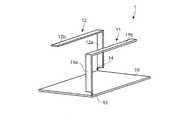
図1Aは、地板が1つである場合のアンテナ装置1の構成の一例を示す図、図1Bは、地板が2つである場合の本実施の形態にかかるアンテナ装置2の構成の一例を示す図である。 FIG. 1A is a diagram showing an example of the configuration of the
図1Aに示すアンテナ装置1は、地板10、第1のアンテナ11、および、第2のアンテナ12を備える。 The
第1のアンテナ11は、逆Lアンテナであり、矩形状の地板10に対し垂直に伸びる第1のエレメント11aと、地板10の長辺に沿って延びる第2のエレメント11bとを有する。 The
また、第1のアンテナ11は、地板10の角部と第1の給電点13を介して接続されている。 Further, the
第2のアンテナ12も逆Lアンテナであり、地板10に対し第1のアンテナ11の第1のエレメント11aと同じ側に垂直に伸びる第3のエレメント12aと、地板10の長辺に沿って延びる第4のエレメント12bとを有する。 The
また、第2のアンテナ12は、第1の給電点13が位置する角部と対角の位置にある地板10の角部と第2の給電点14を介して接続されている。 Further, the
そして、第2のアンテナ12の第4のエレメント12bが第3のエレメント12aから伸びる方向は、第1のアンテナ11の第2のエレメント11bが第1のエレメント11aから伸びる方向と逆の方向となっている。 The direction in which the
また、第1のアンテナ11の第2のエレメント11bは、第2のアンテナ12の第4のエレメント12bと地板10からみて同じ高さとなるよう設けられている。 Further, the
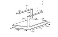
一方、図1Bに示す本実施形態にかかるアンテナ装置2は、第1の地板20a、第2の地板20b、第1のアンテナ21、および、第2のアンテナ22を備える。 On the other hand, the
ここで、第1の地板20aと第2の地板20bとは平行に設けられている。なお、第1の地板20aと第2の地板20bとは、必ずしも厳密に平行に設けられていなければ本発明の作用効果が得られないというものではなく、一定の誤差は許容され得ることは言うまでもない。 Here, the first
すなわち、第1の地板20aと第2の地板20bとは略平行に設けられていればよい。換言すれば、第1の地板20aと第2の地板20bとは概ね同じ方向に広がっていることを意味する。また、第1の地板20aと第2の地板20bの形状は完全に重なる形状である必要もない。 That is, the first
第1のアンテナ21は、逆Lアンテナであり、矩形状の第1の地板20aに対し垂直に伸びる第1のエレメント21aと、第1の地板20aの長辺に沿って延びる第2のエレメント21bとを有する。 The
また、第1のアンテナ21は、第1の地板20aの角部と第1の給電点23を介して接続されている。 Further, the
ここで、第2の地板20bには、第1のエレメント21aが外側に突き出ることなく、第1の地板20aに対し垂直に伸ばしてアンテナ装置2を小型化できるようにするため、切り欠きが形成されている。 Here, a notch is formed in the second
第2のアンテナ22も、逆Lアンテナであり、第1の地板20aに対し第1のアンテナ21の第1のエレメント21aと同じ側に垂直に伸びる第3のエレメント22aと、第2の地板20bの長辺に沿って延びる第4のエレメント22bとを有する。 The
第2のアンテナ22は、第1の給電点23が位置する第1の地板20aの角部と対角の位置にある第2の地板20bの角部と第2の給電点24を介して接続されている。 The
そして、第2のアンテナ22の第4のエレメント22bが第3のエレメント22aから伸びる方向は、第1のアンテナ21の第2のエレメント21bが第1のエレメント21aから伸びる方向と略逆の方向となっている。 The direction in which the
また、第1のアンテナ21の第2のエレメント21bは、第2のアンテナ22の第4のエレメント22bと第2の地板20bからみて同じ高さとなるよう設けられている。 Further, the
図1Aに示すアンテナ装置1では、1つの地板10に2つのアンテナ(第1のアンテナ11および第2のアンテナ12)が設けられることによりアンテナ結合が生じ、アンテナ効率が低下するとともに、相関係数が大きくなる。 In the
これを防ぐためには地板10を大きくすることが考えられるが、地板10を大きくすると、アンテナ装置1を小型化することが難しくなる。 In order to prevent this, it is conceivable to increase the size of the
これに対し、図1Bに示すアンテナ装置2では、互いに平行な2つの地板(第1の地板20aおよび第2の地板20b)のそれぞれに第1のアンテナ21と第2のアンテナ22とを第1の給電点23と第2の給電点24とを介して接続する構成とした。 On the other hand, in the
これにより、アンテナ性能の劣化を防止しつつ、小型化を実現することが可能となる。以下に、本実施形態にかかるアンテナ装置2のアンテナ性能について説明する。 This makes it possible to realize miniaturization while preventing deterioration of antenna performance. The antenna performance of the
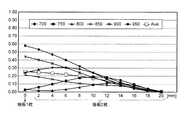
図2Aは、2つの地板間の距離とアンテナ間の相関係数との間の関係を示す図である。図2Bは、2つの地板間の距離と第1のアンテナ21のアンテナ効率との間の関係を示す図である。図2Cは、2つの地板間の距離と第2のアンテナ22のアンテナ効率との間の関係を示す図である。 FIG. 2A is a diagram showing the relationship between the distance between the two main plates and the correlation coefficient between the antennas. FIG. 2B is a diagram showing the relationship between the distance between the two main plates and the antenna efficiency of the
図2A、図2B、および、図2Cは、地板間の距離(横軸。単位はmm)に対する相関係数またはアンテナ効率のシミュレーション結果の値を示している。シミュレーションは、複数の周波数(700、750、800、850、900、950MHz)に対して行い、図2A、2B、2Cには、周波数ごとに地板間の距離に対するアンテナ間の相関係数またはアンテナ効率の値の推移を示すとともに、それらの平均値を示している。 2A, 2B, and 2C show the value of the simulation result of the correlation coefficient or the antenna efficiency with respect to the distance between the main plates (horizontal axis, in mm). The simulation was performed for multiple frequencies (700, 750, 800, 850, 900, 950 MHz), and FIGS. 2A, 2B, and 2C show the correlation coefficient between antennas or the antenna efficiency with respect to the distance between the main plates for each frequency. The transition of the values of is shown, and the average value of them is shown.
ここで、横軸における0mmは地板が1枚であることを表している。また、横軸のそれ以降の目盛りは2枚の地板間の距離を表しており、図1Bに示した第1の地板20aと第2の地板20bとの間の距離が2mmずつ大きくなっている。 Here, 0 mm on the horizontal axis indicates that there is one main plate. Further, the scale after that on the horizontal axis represents the distance between the two main plates, and the distance between the first
図2Aに示すように、アンテナ間の相関係数は、その平均値を参照すると、2つの地板間の距離が離れるにつれて低下している。すなわち、アンテナ間の相関係数は、2つの地板間の距離を離すにつれて改善傾向がみられるといえる。 As shown in FIG. 2A, the correlation coefficient between the antennas decreases as the distance between the two main plates increases with reference to the average value. That is, it can be said that the correlation coefficient between the antennas tends to improve as the distance between the two main plates increases.
また、図2Bに示すように、第1のアンテナ11のアンテナ効率も、その平均値を参照すると、2つの地板間の距離が離れるにつれて上昇している。すなわち、第1のアンテナ11のアンテナ効率は、2つの地板間の距離を離すにつれて改善傾向がみられるといえる。 Further, as shown in FIG. 2B, the antenna efficiency of the
また、図2Cに示すように、第2のアンテナ12のアンテナ効率は、その平均値を参照すると、2つの地板間の距離が12mmまでであれば、地板が1枚の場合と同等もしくはそれ以上の性能を示しており、少なくとも地板距離が12mmまでは改善傾向がみられるといえる。 Further, as shown in FIG. 2C, the antenna efficiency of the
このように、図1Bに示したアンテナ装置2の性能が改善される理由は、図1Bに示したように、平行に設けられた異なる2つの地板にアンテナがそれぞれ配置されるため、アンテナ装置2の電流分布および放射パターンの対称性が、図1Aに示したアンテナ装置1の電流分布および放射パターンの対称性よりも崩れるためである。 In this way, the reason why the performance of the
つぎに、図1Bに示したアンテナ装置2における第1の地板20aと第2の地板20bとの間の距離と性能の改善との関係について説明する。 Next, the relationship between the distance between the
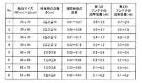
図3は、アンテナ装置2における第1の地板20aと第2の地板20bとの間の距離と性能の改善との関係について説明する図である。 FIG. 3 is a diagram illustrating the relationship between the distance between the first
図3には、サイズの異なる8つのアンテナ装置2でシミュレーションを行った結果が示されている。 FIG. 3 shows the results of simulating with eight
具体的には、第1の地板20aと第2の地板20bの短辺の長さが同じWであり、かつ、長辺の長さが同じLである場合に、第1の地板20aと第2の地板20bとの間の距離Dを変化させてシミュレーションを行った結果が8つ示されている。 Specifically, when the short side lengths of the
また、図3における相関係数の改善、第1のアンテナ21の効率改善、および、第2のアンテナ22の効率改善の評価値は、700MHzから950MHzまでの帯域平均値である。ここで相関係数の改善および効率改善の評価値は、地板が1枚の場合の相関係数または効率に対しての改善の程度を表す値である。 Further, the evaluation values of the improvement of the correlation coefficient, the efficiency improvement of the
図3に示すとおり、地板が1枚の場合に比べて、地板を2枚構成とすることで、サイズの異なる8つのアンテナ装置のいずれにおいても、相関係数および第1のアンテナ21の効率は(25×70の相関係数を除き)改善されているといえる。また、第2のアンテナ22の効率についても、地板が1枚の場合に比べて劣化なし(やや改善している)といえる。 As shown in FIG. 3, the correlation coefficient and the efficiency of the
ここで、相関係数に安定的な改善がみられ、かつ、第1のアンテナ21の効率については0.3dBを上回ることがある場合に顕著な改善があったとみなす。 Here, it is considered that there is a remarkable improvement when the correlation coefficient is stably improved and the efficiency of the
この場合、図3に示したNo.1〜8のケースのうち、No.3〜6のケースについて顕著な改善があったといえる。 In this case, No. 3 shown in FIG. Of the
これらのケースについては、第1の地板20aおよび第2の地板20bの長辺の長さLが70mm以上90mm以下であり、かつ、第1の地板20aおよび第2の地板20bの短辺の長さWが(25+t)mm(ここで、tは10以上20以下)である場合に、第1の地板20aと第2の地板20bとの間の距離Dが2mm以上(16−2t/5)mm以下となっている。 In these cases, the length L of the long side of the first
すなわち、このような条件を満たす場合に、アンテナ性能に顕著な改善がみられるといえる。例えば、W=35mmでt=10の場合にはDは12mm以下となり、W45mmでt=20の場合にはDは8mm以下となる。 That is, it can be said that the antenna performance is significantly improved when such a condition is satisfied. For example, when W = 35 mm and t = 10, D is 12 mm or less, and when
なお、ここで説明したケースは、地板を2枚構成とした場合に、あくまで著しく顕著な効果が得られる寸法の説明であって、地板を2枚構成とすることによって、例えばtが10より小さい場合や20より大きい場合でも一定の改善効果があることは言うまでもない。 It should be noted that the case described here is an explanation of dimensions in which a remarkably remarkable effect can be obtained when the main plate is composed of two sheets, and for example, t is smaller than 10 when the main plate is composed of two sheets. Needless to say, there is a certain improvement effect even when the case is larger than 20 or the case is larger than 20.
つぎに、アンテナの数が2つより多い場合について説明する。図4Aは、アンテナの数が4本である場合のアンテナ装置3の構成の一例を示す図であり、図4Bは、アンテナの数が4本である場合のアンテナ装置4の構成の他の一例を示す図である。 Next, a case where the number of antennas is more than two will be described. FIG. 4A is a diagram showing an example of the configuration of the
図4Aに示すアンテナ装置3は、第1の地板30a、第2の地板30b、第1のアンテナ31、第2のアンテナ32、第3のアンテナ33、および、第4のアンテナ34を備える。 The
ここで、第1の地板30aと第2の地板30bとは平行に設けられている。 Here, the first
第1のアンテナ31は逆Lアンテナであり、矩形状の第2の地板30bに対し垂直に伸びる第1のエレメント31aと、第2の地板30bの長辺に沿って延びる第2のエレメント31bとを有する。 The
また、第1のアンテナ31は、第2の地板30bの角部と第1の給電点35を介して接続されている。 Further, the
第2のアンテナ32も、逆Lアンテナであり、第1の地板30aに対し第1のアンテナ31の第1のエレメント31aと同じ側に垂直に伸びる第3のエレメント32aと、第2の地板30bの長辺に沿って延びる第4のエレメント32bとを有する。 The
第2のアンテナ32は、第1の給電点35が位置する第2の地板30bの角部と同じ側にある第1の地板30aの角部と第2の給電点36を介して接続されている。 The
ここで、第2の地板30bには、第3のエレメント32aが外側に突き出ることなく、第1の地板30aに対し垂直に伸ばしてアンテナ装置3を小型化できるようにするため、切り欠きが形成されている。 Here, a notch is formed in the second
そして、第2のアンテナ32の第4のエレメント32bが第3のエレメント32aから伸びる方向は、第1のアンテナ31の第2のエレメント31bが第1のエレメント31aから伸びる方向と同じ方向となっている。 The direction in which the
また、第1のアンテナ31の第2のエレメント31bは、第2のアンテナ32の第4のエレメント32bと第2の地板30bからみて同じ高さとなるよう設けられている。 Further, the
第3のアンテナ33も逆Lアンテナであり、第1の地板30aに対し第1のアンテナ31の第1のエレメント31aと反対側に垂直に伸びる第5のエレメント33aと、第1の地板30aの長辺に沿って延びる第6のエレメント33bとを有する。 The
第3のアンテナ33は、第2の給電点36が位置する第2の地板30bの角部と対角の位置ある第1の地板30aの角部と第3の給電点37を介して接続されている。 The
第4のアンテナ34も逆Lアンテナであり、第2の地板30bに対し第1のアンテナ31の第1のエレメント31aと反対側に垂直に伸びる第7のエレメント34aと、第1の地板30aの長辺に沿って延びる第8のエレメント34bとを有する。 The
第4のアンテナ34は、第3の給電点37が位置する第1の地板30aの角部と同じ側にある第2の地板30bの角部と第4の給電点38を介して接続されている。 The
ここで、第1の地板30aには、第7のエレメント34aが外側に突き出ることなく、第2の地板30bに対し垂直に伸ばしてアンテナ装置3を小型化できるようにするため、切り欠きが形成されている。 Here, a notch is formed in the first
そして、第4のアンテナ34の第8のエレメント34bが第7のエレメント34aから伸びる方向は、第3のアンテナ33の第6のエレメント33bが第5のエレメント33aから伸びる方向と同じ方向となっている。 The direction in which the
また、第3のアンテナ33の第6のエレメント33bは、第4のアンテナ34の第8のエレメント34bと第1の地板30aからみて同じ高さとなるよう設けられている。 Further, the
図4Bに示すアンテナ装置4は、第1の地板40a、第2の地板40b、第1のアンテナ41、第2のアンテナ42、第3のアンテナ43、および、第4のアンテナ44を備える。 The
ここで、第1の地板40aと第2の地板40bとは平行に設けられている。 Here, the first
第1のアンテナ41は逆Lアンテナであり、矩形状の第2の地板40bに対し垂直に伸びる第1のエレメント41aと、第2の地板40bの長辺に沿って延びる第2のエレメント41bとを有する。 The
また、第1のアンテナ41は、第2の地板40bの角部と第1の給電点45を介して接続されている。 Further, the
第2のアンテナ42も逆Lアンテナであり、第1の地板40aに対し第1のアンテナ41の第1のエレメント41aと同じ側に垂直に伸びる第3のエレメント42aと、第2の地板40bの長辺に沿って延びる第4のエレメント42bとを有する。 The
第2のアンテナ42は、第1の給電点45が位置する第2の地板40bの角部と同じ側にある第1の地板40aの角部と第2の給電点46を介して接続されている。 The
ここで、第2の地板40bには、第3のエレメント42aが外側に突き出ることなく、第1の地板40aに対し垂直に伸ばしてアンテナ装置4を小型化できるようにするため、切り欠きが形成されている。 Here, a notch is formed in the second
そして、第2のアンテナ42の第4のエレメント42bが第3のエレメント42aから伸びる方向は、第1のアンテナ41の第2のエレメント41bが第1のエレメント41aから伸びる方向と同じ方向となっている。 The direction in which the
また、第1のアンテナ41の第2のエレメント41bは、第2のアンテナ42の第4のエレメント42bと第2の地板40bからみて同じ高さとなるよう設けられている。 Further, the
第3のアンテナ43も逆Lアンテナであり、第1の地板40aに対し第1のアンテナ41の第1のエレメント41aと反対側に垂直に伸びる第5のエレメント43aと、第1の地板40aの長辺に沿って延びる第6のエレメント43bとを有する。 The
第3のアンテナ43は、第2の給電点46が位置する第1の地板40aの角部と対角の位置にある第2の地板40bの角部と第3の給電点47を介して接続されている。 The
ここで、第1の地板40aには、第5のエレメント43aが外側に突き出ることなく、第2の地板40bに対し垂直に伸ばしてアンテナ装置4を小型化できるようにするため、切り欠きが形成されている。 Here, a notch is formed in the first
第4のアンテナ44も逆Lアンテナであり、第1の地板40aに対し第1のアンテナ41の第1のエレメント41aと反対側に垂直に伸びる第7のエレメント44aと、第1の地板40aの長辺に沿って延びる第8のエレメント44bとを有する。 The
第4のアンテナ44は、第3の給電点47が位置する第2の地板40bの角部と同じ側にある第1の地板40aの角部と第4の給電点48を介して接続されている。 The
そして、第4のアンテナ44の第8のエレメント44bが第7のエレメント44aから伸びる方向は、第3のアンテナ43の第6のエレメント43bが第5のエレメント43aから伸びる方向と同じ方向となっている。 The direction in which the
また、第3のアンテナ43の第6のエレメント43bは、第4のアンテナ44の第8のエレメント44bと第1の地板40aからみて同じ高さとなるよう設けられている。 Further, the
図4Aおよび図4Bに示したアンテナ装置3、4においても、図1Bに示したアンテナ装置2と同様に、アンテナ装置3、4の電流分布および放射パターンの対称性が崩れている。そのため、相関係数、および、アンテナの効率が顕著に改善される。 In the
なお、上記実施の形態では、アンテナ装置2〜4を小型化するため、地板に切り欠きを形成してアンテナエレメントに切り欠きを通過させることとしたが、必要なだけ小型化できていれば必ずしも切り欠きを設ける必要はない。 In the above embodiment, in order to reduce the size of the
図5は、第1の地板50aおよび第2の地板50bがある場合に第2の地板50bに切り欠きを設けないアンテナ装置5の構成の一例を示す図である。 FIG. 5 is a diagram showing an example of the configuration of the
このアンテナ装置5は、第1の地板50a、第2の地板50b、第1のアンテナ51、および、第2のアンテナ52を備える。 The
ここで、第1の地板50aと第2の地板50bとは平行に設けられている。 Here, the first
第1のアンテナ51は逆Lアンテナであり、矩形状の第1の地板50aに対し垂直に伸びる第1のエレメント51aと、第1の地板50aの長辺に沿って延びる第2のエレメント51bとを有する。 The
また、第1のアンテナ51は、第1の地板50aの角部と第1の給電点53を介して接続されている。 Further, the
ただし、図1Bに示したアンテナ装置2とは異なり、第2の地板50bには第1のエレメント51aを通過させる切り欠きはなく、第1のエレメント51aは第2の地板50bの外側を通過して第1の地板50aに対し垂直に伸びている。 However, unlike the
第2のアンテナ52も逆Lアンテナであり、第1の地板50aに対し第1のアンテナ51の第1のエレメント51aと同じ側に垂直に伸びる第3のエレメント52aと、第2の地板50bの長辺に沿って延びる第4のエレメント52bとを有する。 The
第2のアンテナ52は、第1の給電点53が位置する第1の地板50aの角部と対角の位置にある第2の地板50bの角部と第2の給電点54を介して接続されている。 The
そして、第2のアンテナ52の第4のエレメント52bが第3のエレメント52aから伸びる方向は、第1のアンテナ51の第2のエレメント51bが第1のエレメント51aから伸びる方向と略逆の方向となっている。 The direction in which the
また、第1のアンテナ51の第2のエレメント51bは、第2のアンテナ52の第4のエレメント52bと第2の地板50bからみて同じ高さとなるよう設けられている。 Further, the
この場合も、図1Bに示したアンテナ装置2と同様に、アンテナ装置5の電流分布および放射パターンの対称性が崩れている。そのため、相関係数、および、アンテナの効率が顕著に改善される。 Also in this case, similarly to the
なお、上述した実施形態においては、エレメントの一部が折れ曲がっている逆Lアンテナを例として説明したが、本発明の技術的な範囲としては、逆Lアンテナに限定されるものではなく、例えばモノポールアンテナ、ループアンテナ、その他線状アンテナあるいはダイポールアンテナであってもよく、特に限定はされない。 In the above-described embodiment, an inverted L antenna in which a part of the element is bent has been described as an example, but the technical scope of the present invention is not limited to the inverted L antenna, for example, a monopole. It may be a pole antenna, a loop antenna, another linear antenna, or a dipole antenna, and is not particularly limited.
本開示に係るアンテナ装置は、複数のアンテナを用いて通信を行うアンテナ装置に適用するのに好適である。 The antenna device according to the present disclosure is suitable for application to an antenna device that communicates using a plurality of antennas.
1,2,3,4,5 アンテナ装置
10 地板
20a,30a,40a,50a 第1の地板
20b,30b,40b,50b 第2の地板
11,21,31,41,51 第1のアンテナ
11a,21a,31a,41a,51a 第1のエレメント
11b,21b,31b,41b,51b 第2のエレメント
12,22、32,42,52 第2のアンテナ
12a,22a,32a,42a,52a 第3のエレメント
12b,22b,32b,42b,52b 第4のエレメント
13,23,35,45,53 第1の給電点
14,24,36,46,54 第2の給電点
33,43 第3のアンテナ
33a,43a 第5のエレメント
33b,43b 第6のエレメント
34,44 第4のアンテナ
34a,44a 第7のエレメント
34b,44b 第8のエレメント
37,47 第3の給電点
38,48 第4の給電点1,2,3,4,5
Claims (8)
Translated fromJapanese第2のアンテナと、
前記第1のアンテナが第1の給電部を介して接続される第1の地板と、
前記第2のアンテナが第2の給電部を介して接続される第2の地板と、を備え、
前記第1の地板と前記第2の地板とが略平行に設けられることを特徴とするアンテナ装置。The first antenna and
With the second antenna
The first main plate to which the first antenna is connected via the first feeding portion,
A second main plate to which the second antenna is connected via a second feeding portion is provided.
An antenna device characterized in that the first main plate and the second main plate are provided substantially in parallel.
Priority Applications (3)
| Application Number | Priority Date | Filing Date | Title |
|---|---|---|---|
| JP2019064965AJP2020167489A (en) | 2019-03-28 | 2019-03-28 | Antenna device |
| US16/830,949US11476570B2 (en) | 2019-03-28 | 2020-03-26 | Antenna apparatus |
| DE102020108588.5ADE102020108588A1 (en) | 2019-03-28 | 2020-03-27 | ANTENNA DEVICE |
Applications Claiming Priority (1)
| Application Number | Priority Date | Filing Date | Title |
|---|---|---|---|
| JP2019064965AJP2020167489A (en) | 2019-03-28 | 2019-03-28 | Antenna device |
Publications (1)
| Publication Number | Publication Date |
|---|---|
| JP2020167489Atrue JP2020167489A (en) | 2020-10-08 |
Family
ID=72604658
Family Applications (1)
| Application Number | Title | Priority Date | Filing Date |
|---|---|---|---|
| JP2019064965APendingJP2020167489A (en) | 2019-03-28 | 2019-03-28 | Antenna device |
Country Status (3)
| Country | Link |
|---|---|
| US (1) | US11476570B2 (en) |
| JP (1) | JP2020167489A (en) |
| DE (1) | DE102020108588A1 (en) |
Citations (2)
| Publication number | Priority date | Publication date | Assignee | Title |
|---|---|---|---|---|
| JP2015111763A (en)* | 2013-12-06 | 2015-06-18 | 日立金属株式会社 | Polarization diversity antenna and radio communication apparatus |
| JP2018107783A (en)* | 2016-12-27 | 2018-07-05 | 財團法人工業技術研究院Industrial Technology Research Institute | Multiantenna communication device |
Family Cites Families (4)
| Publication number | Priority date | Publication date | Assignee | Title |
|---|---|---|---|---|
| US7388550B2 (en)* | 2005-10-11 | 2008-06-17 | Tdk Corporation | PxM antenna with improved radiation characteristics over a broad frequency range |
| JP2010130115A (en) | 2008-11-25 | 2010-06-10 | Samsung Electronics Co Ltd | Antenna device |
| US20130082893A1 (en)* | 2011-09-30 | 2013-04-04 | Raytheon Company | Co-phased, dual polarized antenna array with broadband and wide scan capability |
| US10535917B1 (en)* | 2018-05-03 | 2020-01-14 | First Rf Corporation | Antenna structure for use with a horizontally polarized signal |
- 2019
- 2019-03-28JPJP2019064965Apatent/JP2020167489A/enactivePending
- 2020
- 2020-03-26USUS16/830,949patent/US11476570B2/enactiveActive
- 2020-03-27DEDE102020108588.5Apatent/DE102020108588A1/enactiveGranted
Patent Citations (2)
| Publication number | Priority date | Publication date | Assignee | Title |
|---|---|---|---|---|
| JP2015111763A (en)* | 2013-12-06 | 2015-06-18 | 日立金属株式会社 | Polarization diversity antenna and radio communication apparatus |
| JP2018107783A (en)* | 2016-12-27 | 2018-07-05 | 財團法人工業技術研究院Industrial Technology Research Institute | Multiantenna communication device |
Also Published As
| Publication number | Publication date |
|---|---|
| DE102020108588A1 (en) | 2020-10-01 |
| US20200313291A1 (en) | 2020-10-01 |
| US11476570B2 (en) | 2022-10-18 |
Similar Documents
| Publication | Publication Date | Title |
|---|---|---|
| CN109935964B (en) | An antenna unit and antenna array | |
| US8164525B2 (en) | MIMO antenna and communication device using the same | |
| CN108432088B (en) | Phased array antenna with sub-arrays | |
| JP6240202B2 (en) | Self-grounding antenna device | |
| WO2019161116A9 (en) | Antenna modules for phased array antennas | |
| JP6297337B2 (en) | Antenna assembly and communication device including the antenna assembly | |
| US20140320377A1 (en) | Multi-channel multi-sector smart antenna system | |
| US8009102B2 (en) | Multi-band antenna and multi-band antenna system with enhanced isolation characteristic | |
| US9112260B2 (en) | Microstrip antenna | |
| US9065180B2 (en) | Surface for filtering a plurality of frequency bands | |
| US10109928B2 (en) | Antenna system and wireless device | |
| US20130285865A1 (en) | Printed slot-type directional antenna, and system comprising an array of a plurality of printed slot-type directional antennas | |
| CN107919525B (en) | Antenna system | |
| WO2019137522A1 (en) | Antenna unit, mimo antenna and handheld device | |
| US10644389B1 (en) | Double-frequency antenna structure with high isolation | |
| JP2020167489A (en) | Antenna device | |
| CN106099390A (en) | Antenna system and wireless device | |
| KR20140018620A (en) | Micro-miniature antenna having dual-polarization | |
| US20210013629A1 (en) | Multi-beam yagi-based mimo antenna system | |
| KR101328530B1 (en) | Slot antenna apparatus having integrated structure and wireless communication system using the apparatus | |
| US20170301978A1 (en) | Antenna unit and antenna system | |
| JP2011217109A (en) | Antenna device | |
| US20200212580A1 (en) | Antenna system, communication terminal and base station | |
| JP5016790B2 (en) | antenna | |
| JP2020162056A (en) | Antenna device |
Legal Events
| Date | Code | Title | Description |
|---|---|---|---|
| RD02 | Notification of acceptance of power of attorney | Free format text:JAPANESE INTERMEDIATE CODE: A7422 Effective date:20190625 | |
| RD04 | Notification of resignation of power of attorney | Free format text:JAPANESE INTERMEDIATE CODE: A7424 Effective date:20191021 | |
| A621 | Written request for application examination | Free format text:JAPANESE INTERMEDIATE CODE: A621 Effective date:20210726 | |
| A977 | Report on retrieval | Free format text:JAPANESE INTERMEDIATE CODE: A971007 Effective date:20220516 | |
| A131 | Notification of reasons for refusal | Free format text:JAPANESE INTERMEDIATE CODE: A131 Effective date:20220524 | |
| A521 | Request for written amendment filed | Free format text:JAPANESE INTERMEDIATE CODE: A523 Effective date:20220722 | |
| A02 | Decision of refusal | Free format text:JAPANESE INTERMEDIATE CODE: A02 Effective date:20220823 |