JP2020162779A - Mounting instrument - Google Patents
Mounting instrumentDownload PDFInfo
- Publication number
- JP2020162779A JP2020162779AJP2019065045AJP2019065045AJP2020162779AJP 2020162779 AJP2020162779 AJP 2020162779AJP 2019065045 AJP2019065045 AJP 2019065045AJP 2019065045 AJP2019065045 AJP 2019065045AJP 2020162779 AJP2020162779 AJP 2020162779A
- Authority
- JP
- Japan
- Prior art keywords
- needle
- mounting
- movable member
- hole
- needle portion
- Prior art date
- Legal status (The legal status is an assumption and is not a legal conclusion. Google has not performed a legal analysis and makes no representation as to the accuracy of the status listed.)
- Pending
Links
- 238000003780insertionMethods0.000claimsabstractdescription23
- 230000037431insertionEffects0.000claimsabstractdescription23
- 230000000149penetrating effectEffects0.000claimsabstractdescription8
- 238000000605extractionMethods0.000claimsabstractdescription4
- 238000005192partitionMethods0.000claimsdescription3
- 208000015181infectious diseaseDiseases0.000abstractdescription5
- XLYOFNOQVPJJNP-UHFFFAOYSA-NwaterSubstancesOXLYOFNOQVPJJNP-UHFFFAOYSA-N0.000description52
- 230000002093peripheral effectEffects0.000description14
- 206010033675panniculitisDiseases0.000description13
- 210000004304subcutaneous tissueAnatomy0.000description13
- 239000000463materialSubstances0.000description11
- 206010019280Heart failuresDiseases0.000description5
- 230000004048modificationEffects0.000description5
- 238000012986modificationMethods0.000description5
- -1polyethylenePolymers0.000description5
- 229920005989resinPolymers0.000description5
- 239000011347resinSubstances0.000description5
- 239000000853adhesiveSubstances0.000description4
- 230000001070adhesive effectEffects0.000description4
- 210000001124body fluidAnatomy0.000description4
- 239000010839body fluidSubstances0.000description4
- 230000007423decreaseEffects0.000description4
- 238000010586diagramMethods0.000description4
- 239000004721Polyphenylene oxideSubstances0.000description3
- 210000004207dermisAnatomy0.000description3
- 239000002934diureticSubstances0.000description3
- 210000002615epidermisAnatomy0.000description3
- 206010007559Cardiac failure congestiveDiseases0.000description2
- 206010030113OedemaDiseases0.000description2
- 239000004696Poly ether ether ketoneSubstances0.000description2
- 239000004952PolyamideSubstances0.000description2
- 229920000122acrylonitrile butadiene styrenePolymers0.000description2
- 229920001577copolymerPolymers0.000description2
- 230000001882diuretic effectEffects0.000description2
- 239000005038ethylene vinyl acetateSubstances0.000description2
- 239000012530fluidSubstances0.000description2
- 239000007769metal materialSubstances0.000description2
- 229920001200poly(ethylene-vinyl acetate)Polymers0.000description2
- 229920002647polyamidePolymers0.000description2
- 229920001707polybutylene terephthalatePolymers0.000description2
- 229920000728polyesterPolymers0.000description2
- 229920002530polyetherether ketonePolymers0.000description2
- 229920000139polyethylene terephthalatePolymers0.000description2
- 239000005020polyethylene terephthalateSubstances0.000description2
- 229920006324polyoxymethylenePolymers0.000description2
- 229920006380polyphenylene oxidePolymers0.000description2
- 210000003491skinAnatomy0.000description2
- 239000004925Acrylic resinSubstances0.000description1
- 229920000178Acrylic resinPolymers0.000description1
- 229910000838Al alloyInorganic materials0.000description1
- 229920000106Liquid crystal polymerPolymers0.000description1
- 239000004977Liquid-crystal polymers (LCPs)Substances0.000description1
- 239000002033PVDF binderSubstances0.000description1
- 229920008285Poly(ether ketone) PEKPolymers0.000description1
- 229930182556PolyacetalNatural products0.000description1
- 239000004695Polyether sulfoneSubstances0.000description1
- 239000004697PolyetherimideSubstances0.000description1
- 239000004698PolyethyleneSubstances0.000description1
- 239000004642PolyimideSubstances0.000description1
- 239000004734Polyphenylene sulfideSubstances0.000description1
- 239000004743PolypropyleneSubstances0.000description1
- 239000004793PolystyreneSubstances0.000description1
- 229920001328Polyvinylidene chloridePolymers0.000description1
- 229910001069Ti alloyInorganic materials0.000description1
- RTAQQCXQSZGOHL-UHFFFAOYSA-NTitaniumChemical compound[Ti]RTAQQCXQSZGOHL-UHFFFAOYSA-N0.000description1
- XECAHXYUAAWDEL-UHFFFAOYSA-Nacrylonitrile butadiene styreneChemical compoundC=CC=C.C=CC#N.C=CC1=CC=CC=C1XECAHXYUAAWDEL-UHFFFAOYSA-N0.000description1
- 239000004676acrylonitrile butadiene styreneSubstances0.000description1
- 229920001893acrylonitrile styrenePolymers0.000description1
- 239000012790adhesive layerSubstances0.000description1
- 229910052782aluminiumInorganic materials0.000description1
- XAGFODPZIPBFFR-UHFFFAOYSA-NaluminiumChemical compound[Al]XAGFODPZIPBFFR-UHFFFAOYSA-N0.000description1
- 125000003118aryl groupChemical group0.000description1
- 229940030606diureticsDrugs0.000description1
- 229920000554ionomerPolymers0.000description1
- 210000000056organAnatomy0.000description1
- 229920003229poly(methyl methacrylate)Polymers0.000description1
- 229920002492poly(sulfone)Polymers0.000description1
- 239000004417polycarbonateSubstances0.000description1
- 229920000515polycarbonatePolymers0.000description1
- 229920000570polyetherPolymers0.000description1
- 229920006393polyether sulfonePolymers0.000description1
- 229920001601polyetherimidePolymers0.000description1
- 229920000573polyethylenePolymers0.000description1
- 229920001721polyimidePolymers0.000description1
- 239000004926polymethyl methacrylateSubstances0.000description1
- 229920000306polymethylpentenePolymers0.000description1
- 229920000098polyolefinPolymers0.000description1
- 229920000069polyphenylene sulfidePolymers0.000description1
- 229920001155polypropylenePolymers0.000description1
- 229920002223polystyrenePolymers0.000description1
- 229920001343polytetrafluoroethylenePolymers0.000description1
- 239000004810polytetrafluoroethyleneSubstances0.000description1
- 229920006264polyurethane filmPolymers0.000description1
- 239000004800polyvinyl chlorideSubstances0.000description1
- 229920000915polyvinyl chloridePolymers0.000description1
- 239000005033polyvinylidene chlorideSubstances0.000description1
- 229920002981polyvinylidene fluoridePolymers0.000description1
- SCUZVMOVTVSBLE-UHFFFAOYSA-Nprop-2-enenitrile;styreneChemical compoundC=CC#N.C=CC1=CC=CC=C1SCUZVMOVTVSBLE-UHFFFAOYSA-N0.000description1
- 238000007789sealingMethods0.000description1
- 239000010935stainless steelSubstances0.000description1
- 229910001220stainless steelInorganic materials0.000description1
- KKEYFWRCBNTPAC-UHFFFAOYSA-Lterephthalate(2-)Chemical compound[O-]C(=O)C1=CC=C(C([O-])=O)C=C1KKEYFWRCBNTPAC-UHFFFAOYSA-L0.000description1
- 239000010936titaniumSubstances0.000description1
- 229910052719titaniumInorganic materials0.000description1
- GYHCTFXIZSNGJT-UHFFFAOYSA-NtolvaptanChemical compoundCC1=CC=CC=C1C(=O)NC(C=C1C)=CC=C1C(=O)N1C2=CC=C(Cl)C=C2C(O)CCC1GYHCTFXIZSNGJT-UHFFFAOYSA-N0.000description1
- 229960001256tolvaptanDrugs0.000description1
Images


Landscapes
- External Artificial Organs (AREA)
- Media Introduction/Drainage Providing Device (AREA)
Abstract
Description
Translated fromJapanese本開示は装着器具に関する。 The present disclosure relates to a mounting device.
従来から、例えばうっ血性心不全により、顔面・四肢にうっ血が発生することが知られている。このようなうっ血に対して、利尿薬を利用して除水する治療が一般的に行われている。 Conventionally, it has been known that congestion occurs in the face and limbs due to, for example, congestive heart failure. Treatment to remove water using a diuretic is generally performed for such congestion.
特許文献1には、皮膚からの流体又は皮膚下からの流体を被検体から受容するための装置が開示されている。また、特許文献2には、複数のマイクロニードルのアレイを含む、身体から体液を取り出すための装置が開示されている。 Patent Document 1 discloses a device for receiving a fluid from the skin or a fluid from under the skin from a subject. Further,
心不全に伴ううっ血治療として、上述した利尿薬の利用のみの治療では除水しきれず、うっ血が残存する場合がある。うっ血の残存は諸臓器の傷害を進行させ、心不全をさらに悪化させる可能性がある。 As a treatment for congestion associated with heart failure, the above-mentioned treatment using only diuretics may not be able to completely remove water, and congestion may remain. Residual congestion can lead to damage to organs and further exacerbate heart failure.
これに対して、特許文献1及び2に記載されている装置を利用することが考えられる。具体的には、生体表面に装着された後に、針部を生体に穿刺及び抜去し、生体表面に形成された穿刺孔を通じて体液を取り出す装置を用いて、除水治療を行うことが考えられる。特許文献1及び2に記載されている装置によれば、穿刺孔が露出しないため、穿刺孔からの感染リスクを低減できる。しかしながら、除水治療の最中に、特許文献1及び2に開示されている装置に対して外力が作用すると、生体表面上で装置の装着位置が変動する、又は、装置が生体表面から脱落する、おそれがある。装置の装着位置が変動すると除水治療の除水効率が低下する可能性がある。また、装置が生体表面から脱落すると、穿刺孔を覆う適切な位置に装置を再装着することは難しい。そのため、装置の再装着のみならず、針部を再び穿刺及び抜去することで、新たな穿刺孔を生体表面に形成しなければならない場合がある。 On the other hand, it is conceivable to use the devices described in
本開示は、穿刺孔の露出による感染リスクを低減できると共に、除水治療の最中に生体表面での装着状態を維持し易い装着器具を提供することを目的とする。 An object of the present disclosure is to provide a wearing device that can reduce the risk of infection due to exposure of a puncture hole and that can easily maintain a wearing state on the surface of a living body during water removal treatment.
本開示の第1の態様としての装着器具は、生体表面に装着される装着面を備える装着本体と、前記生体表面に挿入可能な針部を備え、前記装着本体に対して移動可能に保持されている可動部材と、を備え、前記可動部材は、前記針部が前記装着面よりも突出する挿入位置と、前記針部が前記装着面よりも突出しない抜去位置と、との間を前記装着本体に対して移動可能であり、前記可動部材には、前記針部の長手方向に貫通する少なくとも1つの貫通孔が形成されている。 The mounting device as the first aspect of the present disclosure includes a mounting body having a mounting surface mounted on the surface of the living body and a needle portion that can be inserted into the surface of the living body, and is movably held with respect to the mounting body. The movable member includes an insertion position in which the needle portion protrudes from the mounting surface and an extraction position in which the needle portion does not protrude from the mounting surface. The movable member is movable with respect to the main body, and the movable member is formed with at least one through hole penetrating in the longitudinal direction of the needle portion.
本開示の1つの実施形態として、前記少なくとも1つの貫通孔は、前記針部を前記長手方向に貫通する貫通孔を含む。 In one embodiment of the present disclosure, the at least one through hole includes a through hole that penetrates the needle portion in the longitudinal direction.
本開示の1つの実施形態として、前記可動部材は、前記針部の基端を支持する針支持部を備え、前記少なくとも1つの貫通孔は、前記針部を前記長手方向に貫通せず、前記針支持部を前記長手方向に貫通する貫通孔を含む。 In one embodiment of the present disclosure, the movable member comprises a needle support portion that supports the proximal end of the needle portion, and the at least one through hole does not penetrate the needle portion in the longitudinal direction. Includes a through hole that penetrates the needle support portion in the longitudinal direction.
本開示の1つの実施形態として、前記装着本体は、前記可動部材を収容する内部空間を区画しており、前記装着本体には、外部と前記内部空間とを連通する吸引開口が形成されている。 As one embodiment of the present disclosure, the mounting body partitions an internal space for accommodating the movable member, and the mounting body is formed with a suction opening for communicating the outside and the internal space. ..
本開示の1つの実施形態として、前記可動部材は、前記針部を複数備え、前記複数の針部の全ての針先で構成される針先集合面は、湾曲面により構成されている。 As one embodiment of the present disclosure, the movable member includes a plurality of the needle portions, and a needle tip collecting surface composed of all the needle tips of the plurality of needle portions is composed of a curved surface.
本開示によれば、穿刺孔の露出による感染リスクを低減できると共に、除水治療の最中に生体表面での装着状態を維持し易い装着器具を提供することができる。 According to the present disclosure, it is possible to provide a wearing device that can reduce the risk of infection due to the exposure of the puncture hole and can easily maintain the wearing state on the surface of the living body during the water removal treatment.
以下、本開示に係る医療用の装着器具の実施形態について図面を参照して例示説明する。各図において共通する部材・部位には同一の符号を付している。 Hereinafter, embodiments of the medical wearing device according to the present disclosure will be illustrated with reference to the drawings. The same reference numerals are given to common members and parts in each figure.
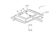
図1は、本開示に係る装着器具の第1実施形態としての装着器具1を用いて行う除水治療の概要を示す図である。装着器具1は、例えばうっ血性心不全などの心不全により入院する患者Pの生体表面BSに装着されて使用される。図1では、患者Pの下股に装着された装着器具1を用いて行う除水治療の概要が示されている。詳細は後述するが、装着器具1によれば、針部11(図4等参照)を穿刺した状態のまま、皮下組織ST(図6参照)の間質に溜まった水分を体外へ除去することができる。図1に示す除水治療は、例えば、利尿薬、トルバプタン等による除水治療に加えて又は代えて行うことができる。また、図1に示す除水治療は、患者Pの浮腫の状態に応じて、例えば2、3日に一度などの、所定の周期で実施される。図1に示す1回の除水治療に要する時間は、患者Pの浮腫の状態によっても異なるが、例えば2〜8時間など、数時間に及ぶことがある。装着器具1は、図1に示す除水治療が行なわれている時だけ生体表面BSに装着される。つまり、患者Pは、入院中に除水治療を行う時にだけ、装着器具1を装着する。 FIG. 1 is a diagram showing an outline of water removal treatment performed by using the wearing device 1 as the first embodiment of the wearing device according to the present disclosure. The wearing device 1 is used by being attached to the biological surface BS of the patient P who is hospitalized due to heart failure such as congestive heart failure. FIG. 1 shows an outline of the water removal treatment performed by using the wearing device 1 mounted on the lower crotch of the patient P. Details will be described later, but according to the wearing device 1, the water accumulated in the interstitium of the subcutaneous tissue ST (see FIG. 6) is removed from the body while the needle portion 11 (see FIG. 4 etc.) is punctured. Can be done. The water removal treatment shown in FIG. 1 can be performed in addition to or in place of, for example, water removal treatment with a diuretic, tolvaptan, or the like. Further, the water removal treatment shown in FIG. 1 is performed in a predetermined cycle, for example, once every two or three days, depending on the state of edema of patient P. The time required for one water removal treatment shown in FIG. 1 varies depending on the state of edema of patient P, but may be several hours, for example, 2 to 8 hours. The attachment device 1 is attached to the biological surface BS only when the water removal treatment shown in FIG. 1 is being performed. That is, the patient P wears the wearing device 1 only when performing the water removal treatment during hospitalization.
図1に示す除水治療は、装着器具1を生体表面BSに装着した状態のままで、間質に溜まった水分を体外へと排出する。この除水治療は、例えば、体外に配置される吸引装置100を、吸引チューブ101等を介して装着器具1に接続することにより、行うことができる。この吸引装置100により吸引することで、針部11(図4等参照)を生体表面BSから生体に穿刺した状態のまま、皮下組織ST(図6参照)の間質に溜まった水分を体外へと排出することができる。この除水治療の詳細は後述する。 In the water removal treatment shown in FIG. 1, the water accumulated in the interstitium is discharged to the outside of the body while the wearing device 1 is attached to the biological surface BS. This water removal treatment can be performed, for example, by connecting a
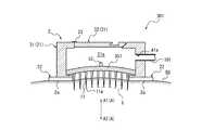
図2は、図1に示す装着器具1の斜視図である。図2では、説明の便宜上、装着器具1に接続される吸引チューブ101を併せて示している。図3は、生体表面BSに装着されている状態の装着器具1の側面図である。図4は、生体表面BSに装着されている状態の装着器具1について、内部機構の概略を示す概略図である。図4では、理解を容易にするため、実際とは異なる大きさで装着器具1の各部を表している。また、図4では、装着器具1の可動部材3が抜去位置にある状態を示している。図5は、図4に示す装着器具1の可動部材3を、抜去位置から挿入位置へと移動させた状態を示している。図6は、可動部材3の詳細を示す詳細断面図である。図6では、可動部材3の針部11が生体表面BSから生体に穿刺された状態、すなわち、図5に示す可動部材3と同じ状態、を示している。 FIG. 2 is a perspective view of the mounting device 1 shown in FIG. In FIG. 2, for convenience of explanation, the
図2〜図6に示すように、装着器具1は、装着本体2と、可動部材3と、を備える。装着本体2は、生体表面BSに装着される装着面2aを備える。可動部材3は、装着本体2に対して移動可能に保持されている。また、可動部材3は、生体表面BSに挿入可能な針部11を備えている。装着面2aとは、装着器具1が生体表面BSに装着されている状態で、生体表面BSに接触している面を意味し、必ずしも粘着等により一体化されていなくてもよい。 As shown in FIGS. 2 to 6, the mounting device 1 includes a
本実施形態の可動部材3は複数の針部11を備えるが、針部11の数は特に限定されず、可動部材3は、少なくとも1つ以上の針部11を備えればよい。但し、装着器具1は、針部11が生体に穿刺されることで形成される穿刺孔を通じて、皮下組織ST(図6参照)の間質に溜まった水分を体外に除去するため、複数の針部11を設けることが好ましい。これにより、穿刺孔を増やすことができ、除水効率を高めることができる。 The
可動部材3は、装着本体2に対して、挿入位置と抜去位置との間で移動可能である。挿入位置とは、針部11が装着本体2の装着面2aよりも突出する位置である(図4参照)。抜去位置とは、針部11が装着本体2の装着面2aよりも突出しない位置である(図5参照)。 The
図6に示すように、可動部材3には、針部11の長手方向Aに貫通する複数の貫通孔Hが形成されている。詳細は後述するが、本実施形態の可動部材3には、針部11の位置で針部11の長手方向Aに貫通する貫通孔h1と、針部11とは異なる位置で針部11の長手方向Aに貫通する貫通孔h2と、の両方が形成されている。 As shown in FIG. 6, the
このように、装着器具1の可動部材3には、針部11の長手方向Aに貫通する貫通孔Hが形成されているため、針部11を生体表面BSから生体に穿刺した状態のまま、貫通孔Hを通じて、皮下組織STの間質に溜まった水分を体外に除去することができる(図6の破線矢印参照)。また、除水治療を行っている間、針部11を生体に穿刺した状態のままにすることができる。そのため、除水治療の最中に装着器具1に外力が作用しても、装着器具1の生体表面BS上の装着位置は変動し難く、生体表面BSからの脱落も抑制できる。つまり、装着器具1によれば、生体に形成された穿刺孔の露出による感染リスクを低減できると共に、除水治療の最中の生体表面BSでの装着状態が維持し易くなる。 As described above, since the
以下、本実施形態の装着器具1の更なる詳細について説明する。 Hereinafter, further details of the mounting device 1 of the present embodiment will be described.
[装着本体2]
本実施形態の装着本体2は、ハウジング21と、装着部材22と、を備える。本実施形態の装着本体2の装着面2aは、装着部材22により構成されている。[Mounting body 2]
The mounting
装着本体2のハウジング21は、可動部材3を収容する内部空間21aを区画している。また、装着本体2のハウジング21には、外部と内部空間21aとを連通する吸引開口41aが形成されている。 The
また、装着本体2のハウジング21の内部空間21aのうち、生体表面BS側となる一端は開放端であり、この開放端の開口を通じて、可動部材3の針部11は、装着本体2の外側へと突出する。この突出する動作により、可動部材3は、抜去位置から挿入位置へと移動する。この詳細は後述する。 Further, in the
より具体的に、本実施形態のハウジング21は、ハウジング本体31と、蓋体32と、を備える。 More specifically, the
ハウジング本体31は、周壁部41と、天壁部42と、内側突出部43と、係止突起部44と、を備える。 The housing
周壁部41は、可動部材3の周囲を取り囲む角筒状の枠部である。図2等に示すように、周壁部41には、外部と内部空間21aとを連通する上述の吸引開口41aが形成されている。この吸引開口41aを通じて、皮下組織ST(図6参照)の間質に溜まった水分をハウジング21外へと排出することができる。この詳細は後述する。 The
天壁部42は、角筒状の周壁部41の一端部に連続して設けられている。天壁部42の中央には開口が形成されている。この天壁部42の開口には、蓋体32が設けられている。蓋体32は、天壁部42の開口を開閉可能に、天壁部42に対してヒンジ33により取り付けられている。 The
天壁部42は、可動部材3に接触して、可動部材3が装着本体2のハウジング21から針部11の抜去方向A1(長手方向Aのうちの一方側の方向)に向かって抜け落ちることを抑制する。つまり、天壁部42は、可動部材3の抜去方向A1の移動を規制するストッパ部を構成している。 The
内側突出部43は、周壁部41の他端部、すなわち、周壁部41のうち生体表面BS側となる開放端から内側に向かって突設されている。 The inner protruding
係止突起部44は、周壁部41の内面から突出している。可動部材3は、後述する針支持部51が係止突起部44により支持されることで、抜去位置が維持される。可動部材3は、図4に示す状態から、所定の押圧力で挿入方向A2に押圧されることで、係止突起部44を乗り越えて、図5に示す挿入位置に移動することができる。 The locking
ハウジング本体31の周壁部41、天壁部42、内側突出部43及び係止突起部44は、例えば、樹脂材料により一体成形してもよい。ハウジング本体31の材料としては、例えば、ポリエチレン、ポリプロピレン、エチレン−プロピレン共重合体等のポリオレフィン;エチレン−酢酸ビニル共重合体(EVA);ポリ塩化ビニル;ポリ塩化ビニリデン;ポリスチレン;ポリアミド;ポリイミド;ポリアミドイミド;ポリカーボネート;ポリ−(4−メチルペンテン−1);アイオノマー;アクリル樹脂;ポリメチルメタクリレート;アクリロニトリル−ブタジエン−スチレン共重合体(ABS樹脂);アクリロニトリル−スチレン共重合体(AS樹脂);ブタジエン−スチレン共重合体;ポリエチレンテレフタレート(PET)、ポリブチレンテレフタレート(PBT)、ポリシクロヘキサンテレフタレート(PCT)等のポリエステル;ポリエーテル;ポリエーテルケトン(PEK);ポリエーテルエーテルケトン(PEEK);ポリエーテルイミド;ポリアセタール(POM);ポリフェニレンオキシド;変性ポリフェニレンオキシド;ポリサルフォン;ポリエーテルサルフォン;ポリフェニレンサルファイド;ポリアリレート;芳香族ポリエステル(液晶ポリマー);ポリテトラフルオロエチレン、ポリフッ化ビニリデン、その他フッ素系樹脂;などの各種樹脂材料が挙げられる。 The
蓋体32は、上述したように、ハウジング本体31の天壁部42の開口を開閉可能に取り付けられている。蓋体32をハウジング本体31に対して開放することで、天壁部42の開口を通じて、ハウジング21の内部空間21aが外部と連通する。 As described above, the
本実施形態の蓋体32には、開閉の際に操作される操作溝部32aが形成されている。操作溝部32aに指を掛けることで、蓋体32の開閉操作を容易に行うことができる。 The
蓋体32がハウジング本体31に対して閉じられた状態では、ハウジング本体31と蓋体32との間にシール部材を介在させることが好ましい。このようにすることで、内部空間21aの密閉性を高めることができる。これにより、除水治療において内部空間21aを減圧し易くなり、除水効率を高めることができる。 When the
蓋体32の材料としては、ハウジング本体31に用いることが可能な上述の材料を用いることができる。ハウジング本体31及び蓋体32を同一の材料から構成されていてもよく、異なる材料から構成されていてもよい。 As the material of the
装着部材22は、周壁部41の生体表面BS側となる開放端面、及び、内側突出部43の生体表面BS側となる面、に積層された粘着部材により構成することができる。装着部材22は、例えば、シート状の樹脂基材(例えば、ポリウレタンフィルム)に粘着層が積層されている、粘着部材としての粘着シートにより構成することができる。 The mounting
但し、装着部材22は、周壁部41の生体表面BS側となる開放端面、及び、内側突出部43の生体表面BS側となる面、に塗布された粘着剤から構成されていてもよい。 However, the mounting
本実施形態では、生体表面BSに装着される装着本体2の装着面2aが、装着部材22の生体表面BS側の面により構成されている。 In the present embodiment, the mounting
[可動部材3]
可動部材3は、上述の針部11を備える。また、本実施形態の可動部材3は、装着本体2の上述のハウジング21に対して移動可能に保持されている。より具体的に、本実施形態の可動部材3は、ハウジング21の内部空間21aに収容された状態で、針部11の長手方向Aに移動可能である。[Movable member 3]
The
具体的に、本実施形態の可動部材3は、針支持部51と、この針支持部51から一方向に向かって突出する複数の針部11と、把持部52と、を備える。 Specifically, the
本実施形態の針支持部51は、ハウジング21のハウジング本体31の周壁部41内に位置し、針部11の抜去方向A1及び挿入方向A2(長手方向Aのうちの抜去方向A1とは反対側の方向)に移動可能である。本実施形態の針支持部51は、ストッパ部としてのハウジング本体31の天壁部42に接触することで、抜去方向A1にそれ以上移動することが規制される。そのため、可動部材3は、ハウジング21のハウジング本体31から抜去方向A1に抜け落ちない。 The
また、本実施形態の針支持部51は、ハウジング本体31の内側突出部43に接触することで、挿入方向A2にそれ以上移動することが規制される。そのため、可動部材3は、ハウジング21のハウジング本体31から挿入方向A2にも抜け落ちない。 Further, the
針支持部51は、針部11の基端を支持している。換言すれば、針部11は、針支持部51から挿入方向A2に向かって突出している。そのため、針部11は、針支持部51の抜去方向A1及び挿入方向A2の移動に追従して移動する。図4に示すように、針部11の針先11aは、針支持部51が係止突起部44に支持されている状態で、ハウジング21の内部空間21a内に位置している。これに対して、図5に示すように、針部11の針先11aは、針支持部51が内側突出部43に接触している状態で、ハウジング21の内部空間21aから外側に飛び出した状態となる。 The
換言すれば、可動部材3は、針部11が装着面2aよりも突出する挿入位置(図5参照)と、針部11が装着面2aよりも突出しない抜去位置(図4参照)と、間を移動可能である。また、本実施形態の可動部材3は、針支持部51が係止突起部44に支持される状態とすることで、抜去位置に維持される。これに対して、本実施形態の可動部材3は、針支持部51が係止突起部44に支持されている係止状態が解除され、挿入方向A2に押し込まれることで、抜去位置から挿入位置に移動する(図5の白抜き矢印参照)。更に、本実施形態の可動部材3は、針支持部51の抜去方向A1側に突設されている把持部52を備える。そのため、把持部52が把持され、外力により抜去方向A1に引き上げられ、針支持部51が再び係止突起部44により支持される係止状態とされることで、本実施形態の可動部材3は、挿入位置から抜去位置に再び移動することができる。 In other words, the
本実施形態において、可動部材3の上述の一連の操作は、蓋体32をハウジング本体31に対いて開放させた状態とすることで、実行可能である。 In the present embodiment, the above-mentioned series of operations of the
針支持部51及び把持部52は、上述したハウジング本体31の材料と同様の樹脂材料から形成可能である。また、針支持部51及び把持部52は、針部11と同じ金属材料から形成されてもよい。 The
針部11の最大外径は、0.1mm〜0.3mmとすることが好ましく、0.1mm〜0.18mmとすることがより好ましい。針部11の最大外径を0.1mm以上とすることで、針部11を挿入した状態での穿刺孔が小さくなり過ぎない。そのため、皮下組織ST(図6参照)の間質に溜まった水分の単位時間当たりの吸引量を、所定量以上に確保することができる。また、針部11の最大外径を0.3mm以下とすることで、針部11の刺通抵抗を下げることができ、穿刺時に患者Pの感じる痛みを軽減することができる。 The maximum outer diameter of the
針部11の穿刺可能長さは、0.2mm〜1.5mmとすることが好ましい。針部11の穿刺可能長さを0.2mm以上とすることで、針部11の針先11aを、表皮S(図6参照)を貫き真皮D(図6参照)まで到達させ易くなる。そのため、皮下組織ST(図6参照)の間質に溜まった水分を吸引し易くなる。また、針部11の穿刺可能長さを1.5mm以下とすることで、針部11の針先11aを、皮下組織ST(図6参照)まで到達し難くすることができる。そのため、患者Pの感じる痛みを軽減することができる。 The punctureable length of the
また、本実施形態の針部11は、針先11aに向かって細くなるテーパ針であるが、長手方向で外径が一様な形状であってもよい。針部11の材料としては、ステンレス鋼、アルミニウムまたはアルミニウム合金、チタンまたはチタン合金等の金属材料を使用することができる。 Further, the
次に、図6を参照して、本実施形態の可動部材3に形成されている貫通孔Hの詳細について説明する。可動部材3には、上述したように、長手方向Aに貫通する少なくとも1つの貫通孔Hが形成されている。本実施形態の可動部材3には、2種類の貫通孔Hが形成されている。1種目の貫通孔Hは、針部11を長手方向Aに貫通する貫通孔h1である。2種目の貫通孔Hは、針部11を長手方向Aに貫通せず、針支持部51を長手方向Aに貫通する貫通孔h2である。以下、貫通孔h1、h2を区別するため、説明の便宜上、貫通孔h1を「第1貫通孔h1」と記載し、貫通孔h2を「第2貫通孔h2」と記載する。 Next, with reference to FIG. 6, the details of the through hole H formed in the
可動部材3に貫通孔Hを設けることで、針部11を生体に穿刺した状態のまま、皮下組織STの間質に溜まった水分を体外へと排出することが可能となる(図6の破線矢印参照)。具体的に、針部11を生体に穿刺した状態で、ハウジング21(図5参照)の内部空間21aを負圧状態にすれば、第1貫通孔h1を通じて、間質に溜まった水分を吸い上げることができる。更に、針部11の周面を伝って生体表面BS上に排出される水分に関しても、第2貫通孔h2を通じて、吸い上げることができる。以上のように、本実施形態の装着器具1によれば、可動部材3よりも抜去方向A1側に位置する吸引開口41a(図5参照)を利用して、内部空間21aを減圧することで、第1貫通孔h1及び第2貫通孔h2を通じて、皮下組織STの間質に溜まった水分を体外に排出できる。 By providing the through hole H in the
本実施形態では、可動部材3の全ての針部11に第1貫通孔h1が形成されているが、一部の針部11のみに第1貫通孔h1を形成してもよい。但し、除水効率を高める観点では、全ての針部11に第1貫通孔h1を設けることが好ましい。 In the present embodiment, the first through hole h1 is formed in all the
第2貫通孔h2が形成される位置は、針部11が設けられていない位置であれば特に限定されないが、複数の針部11の間の位置に設けることが好ましい。このようにすれば、複数の針部11の周囲から生体表面BS上に排出される水分を、1つの第2貫通孔h2を共用させて、効率的に体外に排出することができる。また、可動部材3を長手方向Aで見た平面視において、第2貫通孔h2の位置は、隣接する2つの第1貫通孔h1の中間位置とすることが好ましい。このようにすれば、生体表面BS上における貫通孔Hの位置のばらつきを抑制でき、複数の針部11が穿刺されている穿刺領域の全域から均一に水分を体外へと排出できる。 The position where the second through hole h2 is formed is not particularly limited as long as the
本実施形態の各貫通孔Hの内径は、長手方向Aの全域に亘って一定であるが、長手方向Aの位置によって異なっていてもよい。例えば、各貫通孔Hの内径が、抜去方向A1に向かうにつれて漸減又は漸増してもよい。また、例えば、第1貫通孔h1の形状は、針部11の形状に沿ったテーパ状になっていてもよい。このようにすれば、第1貫通孔h1の内径が一定である場合に比べて、第1貫通孔h1の排出できる単位時間当たりの体液量が増加し、除水効率を上げることができる。 The inner diameter of each through hole H of the present embodiment is constant over the entire area of the longitudinal direction A, but may differ depending on the position of the longitudinal direction A. For example, the inner diameter of each through hole H may gradually decrease or gradually increase toward the extraction direction A1. Further, for example, the shape of the first through hole h1 may be tapered along the shape of the
第1貫通孔h1の内径は、0.08mm〜0.28mmとすることが好ましく、0.08mm〜0.15mmとすることがより好ましい。第2貫通孔h2の内径は、例えば、0.1mm〜1.0mmとすることが好ましい。なお、第2貫通孔h2の内径は、第1貫通孔h1の内径よりも大きいことが好ましい。刺通抵抗の観点から、針部11の外径は小さいことが好ましいため、第1貫通孔h1の内径についても小さいことが好ましい。これに対して、第1貫通孔h1の内径が小さくなると、第1貫通孔h1から排出できる単位時間当たりの体液量が減少し、除水効率は下がる。そのため、第2貫通孔h2を大きくすることで、第1貫通孔h1及び第2貫通孔h2の全体での除水効率を確保することができる。したがって、第2貫通孔h2の内径を、第1貫通孔h1の内径よりも大きくすることが好ましい。 The inner diameter of the first through hole h1 is preferably 0.08 mm to 0.28 mm, more preferably 0.08 mm to 0.15 mm. The inner diameter of the second through hole h2 is preferably 0.1 mm to 1.0 mm, for example. The inner diameter of the second through hole h2 is preferably larger than the inner diameter of the first through hole h1. From the viewpoint of piercing resistance, the outer diameter of the
[装着器具1を用いた除水治療]
次に、本実施形態の装着器具1を用いて行う除水治療の詳細について説明する。[Water removal treatment using wearing device 1]
Next, the details of the water removal treatment performed by using the wearing device 1 of the present embodiment will be described.
図1に示すように、患者Pに対して除水治療を行う際は、例えば下股などの患者Pの対象部位に、装着器具1を装着する。 As shown in FIG. 1, when performing water removal treatment on patient P, the wearing device 1 is attached to the target site of patient P, for example, the lower crotch.
装着器具1を生体表面BSに装着した状態では、可動部材3は抜去位置にある(図4参照)。この状態から、可動部材3を挿入方向A2に押圧し、可動部材3を挿入位置に移動させる(図5の白抜き矢印参照)。これにより、針部11を生体表面BSに穿刺することができる。針部11の針先11aは、表皮S(図6参照)を貫き真皮D(図6参照)に到達する。 When the mounting device 1 is mounted on the biological surface BS, the
そして、針部11が生体に穿刺された状態(図5参照)で、装着本体2のハウジング21の内部空間21aを負圧状態にする。これにより、複数の貫通孔H(本実施形態では複数の第1貫通孔h1及び複数の第2貫通孔h2)を通じて、皮下組織ST(図6参照)の間質に溜まった水分が可動部材3を通過し、内部空間21aのうち可動部材3よりも抜去方向A1側の部分へと吸い上げられる。つまり、皮下組織ST(図6参照)の間質に溜まった水分を、針部11を生体に穿刺した状態のまま、複数の貫通孔Hを通じて、体外に排出できる。具体的には、吸引チューブ101の一端を、ハウジング21のハウジング本体31の吸引開口41aに接続する。また、吸引チューブ101の他端を、吸引装置100(図1参照)に接続する。この状態で、吸引装置100により吸引することで、ハウジング21の内部空間21aを負圧状態にすることができる。ハウジング21の内部空間21aに吸い上げられた水分は、吸引チューブ101を通じて、吸引装置100へと吸引される。 Then, in a state where the
吸引装置100による上述の吸引を、例えば、2〜8時間継続して行うことで、1回の除水治療を完了することができる。 One water removal treatment can be completed by continuously performing the above-mentioned suction by the
次に、上述した装着器具1の第1の変形例としての装着器具201について、図7Aを参照して説明する。図7Aに示すように、装着器具201は、装着本体2と、可動部材203と、を備える。図7Aに示す装着器具201は、図4等に示す装着器具1と比較して、可動部材203の構成のみが相違している。図7Aは、装着本体2の係止突起部44(図4参照)が省略されて描かれている。 Next, the mounting
図7Aに示す可動部材203は、針支持部51と、この針支持部51から一方向に向かって突出する複数の針部211と、把持部52と、を備える。 The
図7Aに示す複数の針部211の全ての針先211aで構成される針先集合面Xは、湾曲面により構成されている。「針先集合面」とは、可動部材の複数の針部の全ての針先を通過するように形成される仮想面を意味する。針先集合面Xにおいて、隣接する針先211aの間の空隙は、全ての針先211aが滑らかに連なるように近似される。 The needle tip gathering surface X composed of all the
より具体的に、図7Aに示す針支持部51は平板状である。また、図7Aに示す複数の針部211の穿刺可能長さは、周縁部から中央部に向かうにつれて短くなっている。このようにすることで、図7Aに示すように、針先集合面Xを、中央部が凹形状となる湾曲面により構成することができる。 More specifically, the
但し、針先集合面Xを湾曲面により構成するための手段は、図7Aに示す手段に限られない。 However, the means for forming the needle tip collecting surface X by the curved surface is not limited to the means shown in FIG. 7A.
図7Bは、上述した装着器具1の第2の変形例としての装着器具301を示す図である。図7Bでは、針支持部351が湾曲板状である。それに対して、図7Bに示す複数の針部11の穿刺可能長さは略一様である。これにより、複数の針部11の針先11aの集合で構成される針先集合面Xが湾曲面となる。このようにすることで、湾曲面から構成される針先集合面Xを実現してもよい。 FIG. 7B is a diagram showing a mounting
本開示に係る装着器具は、上述した実施形態及び変形例に記載した具体的な構成に限られず、特許請求の範囲を逸脱しない限り、種々の変形・変更が可能である。例えば、上述した本実施形態のハウジング21は、ハウジング本体31と、蓋体32と、を備える構成としているが、開閉可能な蓋体32が設けられておらず、開閉不能な天壁部42で覆われる構成としてもよい。かかる場合には、例えば、天壁部42を弾性変形させることで、可動部材3を挿入方向A2に押圧して移動させるようにすればよい。また、針部11を抜去する場合は、除水治療の終了後に装着器具1全体を生体表面BSから取り外すことで、同時に針部11を生体から抜去すればよい。 The mounting device according to the present disclosure is not limited to the specific configuration described in the above-described embodiment and modification, and can be variously modified or modified as long as it does not deviate from the scope of claims. For example, the
本開示は装着器具に関する。 The present disclosure relates to a mounting device.
1、201、301:装着器具
2:装着本体
2a:装着面
3、203:可動部材
11、211:針部
11a、211a:針先
21:ハウジング
21a:内部空間
22:装着部材
31:ハウジング本体
32:蓋体
32a:操作溝部
33:ヒンジ
41:周壁部
41a:吸引開口
42:天壁部
43:内側突出部
44:係止突起部
51、351:針支持部
52:把持部
100:吸引装置
101:吸引チューブ
A:針部の長手方向
A1:針部の抜去方向
A2:針部の挿入方向
D:真皮
H:貫通孔
h1:第1貫通孔
h2:第2貫通孔
P:患者
S:表皮
X:針先集合面
BS:生体表面
ST:皮下組織1, 201, 301: Mounting device 2: Mounting
Claims (5)
Translated fromJapanese前記生体表面に挿入可能な針部を備え、前記装着本体に対して移動可能に保持されている可動部材と、を備え、
前記可動部材は、前記針部が前記装着面よりも突出する挿入位置と、前記針部が前記装着面よりも突出しない抜去位置と、との間を前記装着本体に対して移動可能であり、
前記可動部材には、前記針部の長手方向に貫通する少なくとも1つの貫通孔が形成されている、装着器具。A mounting body with a mounting surface that is mounted on the surface of the living body,
It is provided with a needle portion that can be inserted into the surface of the living body, and a movable member that is movably held with respect to the mounting body.
The movable member is movable with respect to the mounting body between an insertion position in which the needle portion protrudes from the mounting surface and an extraction position in which the needle portion does not protrude from the mounting surface.
A mounting instrument in which the movable member is formed with at least one through hole penetrating in the longitudinal direction of the needle portion.
前記少なくとも1つの貫通孔は、前記針部を前記長手方向に貫通せず、前記針支持部を前記長手方向に貫通する貫通孔を含む、請求項1又は2に記載の装着器具。The movable member includes a needle support portion that supports the base end of the needle portion.
The mounting device according to claim 1 or 2, wherein the at least one through hole includes a through hole that does not penetrate the needle portion in the longitudinal direction but penetrates the needle support portion in the longitudinal direction.
前記装着本体には、外部と前記内部空間とを連通する吸引開口が形成されている、請求項1から3のいずれか1つに記載の装着器具。The mounting body partitions an internal space for accommodating the movable member.
The mounting device according to any one of claims 1 to 3, wherein a suction opening for communicating the outside and the internal space is formed in the mounting body.
前記複数の針部の全ての針先で構成される針先集合面は、湾曲面により構成されている、請求項1から4のいずれか1つに記載の装着器具。The movable member includes a plurality of the needle portions.
The mounting device according to any one of claims 1 to 4, wherein the needle tip collecting surface formed of all the needle tips of the plurality of needle portions is formed of a curved surface.
Priority Applications (1)
| Application Number | Priority Date | Filing Date | Title |
|---|---|---|---|
| JP2019065045AJP2020162779A (en) | 2019-03-28 | 2019-03-28 | Mounting instrument |
Applications Claiming Priority (1)
| Application Number | Priority Date | Filing Date | Title |
|---|---|---|---|
| JP2019065045AJP2020162779A (en) | 2019-03-28 | 2019-03-28 | Mounting instrument |
Publications (1)
| Publication Number | Publication Date |
|---|---|
| JP2020162779Atrue JP2020162779A (en) | 2020-10-08 |
Family
ID=72716943
Family Applications (1)
| Application Number | Title | Priority Date | Filing Date |
|---|---|---|---|
| JP2019065045APendingJP2020162779A (en) | 2019-03-28 | 2019-03-28 | Mounting instrument |
Country Status (1)
| Country | Link |
|---|---|
| JP (1) | JP2020162779A (en) |
Citations (3)
| Publication number | Priority date | Publication date | Assignee | Title |
|---|---|---|---|---|
| JP2004532079A (en)* | 2001-05-11 | 2004-10-21 | ザ プロクター アンド ギャンブル カンパニー | Portable interstitial fluid monitoring system |
| US20050033197A1 (en)* | 2001-12-06 | 2005-02-10 | Cottler Patrick S | Apparatus for fluid transport and related method thereof |
| US20070004989A1 (en)* | 2005-06-29 | 2007-01-04 | Parvinder Dhillon | Device for transdermal sampling |
- 2019
- 2019-03-28JPJP2019065045Apatent/JP2020162779A/enactivePending
Patent Citations (3)
| Publication number | Priority date | Publication date | Assignee | Title |
|---|---|---|---|---|
| JP2004532079A (en)* | 2001-05-11 | 2004-10-21 | ザ プロクター アンド ギャンブル カンパニー | Portable interstitial fluid monitoring system |
| US20050033197A1 (en)* | 2001-12-06 | 2005-02-10 | Cottler Patrick S | Apparatus for fluid transport and related method thereof |
| US20070004989A1 (en)* | 2005-06-29 | 2007-01-04 | Parvinder Dhillon | Device for transdermal sampling |
Similar Documents
| Publication | Publication Date | Title |
|---|---|---|
| JP6029765B2 (en) | Ear pressure equalization tube and insertion device | |
| EP3815629B1 (en) | Compression device | |
| US12161345B2 (en) | Compression device and compression method | |
| EP2982302B1 (en) | Medical applicator | |
| US12251545B2 (en) | Injection analgesia system | |
| CN114391838B (en) | Implanter and method of use | |
| KR20070121731A (en) | Mounting pads, adhesive devices with these mounting pads and methods of applying such devices to patients | |
| JP2020162779A (en) | Mounting instrument | |
| CN111329562A (en) | Combined device for thyroid puncture | |
| KR20180012651A (en) | Disposable Bloodletting Tool | |
| KR101622245B1 (en) | Apparatus for fixing catheter | |
| JP2020162780A (en) | Mounting instrument | |
| US7806859B2 (en) | Safety lancet for taking blood | |
| KR200484648Y1 (en) | Medical tube fixing assembly | |
| US20160339186A1 (en) | Skin adhesive device for use in medical procedures | |
| JP2013180004A (en) | Surgical instrument and nozzle unit for surgical instrument | |
| JP6347888B1 (en) | Protector and medical needle assembly | |
| CN216797780U (en) | Needle assisting device | |
| JP2020162776A (en) | Mounting device | |
| US20140012278A1 (en) | Surgical instrument | |
| CN211408963U (en) | Superfine thoracoscope | |
| US7621278B2 (en) | Eye drape for surgical procedures | |
| CN116600700A (en) | Systems, devices, and methods for analyte sensor insertion | |
| JP4500670B2 (en) | Protector and winged needle assembly | |
| EP4595879A1 (en) | Reinforcement patch |
Legal Events
| Date | Code | Title | Description |
|---|---|---|---|
| A621 | Written request for application examination | Free format text:JAPANESE INTERMEDIATE CODE: A621 Effective date:20211117 | |
| A977 | Report on retrieval | Free format text:JAPANESE INTERMEDIATE CODE: A971007 Effective date:20220930 | |
| A131 | Notification of reasons for refusal | Free format text:JAPANESE INTERMEDIATE CODE: A131 Effective date:20221004 | |
| A521 | Request for written amendment filed | Free format text:JAPANESE INTERMEDIATE CODE: A523 Effective date:20221205 | |
| A02 | Decision of refusal | Free format text:JAPANESE INTERMEDIATE CODE: A02 Effective date:20230214 |