Movatterモバイル変換


[0]ホーム

URL:


JP2020160084A - Specimen rack conveyance device and automatic analysis system - Google Patents

Specimen rack conveyance device and automatic analysis system
Download PDF

Info

Publication number
JP2020160084A
JP2020160084AJP2020107174AJP2020107174AJP2020160084AJP 2020160084 AJP2020160084 AJP 2020160084AJP 2020107174 AJP2020107174 AJP 2020107174AJP 2020107174 AJP2020107174 AJP 2020107174AJP 2020160084 AJP2020160084 AJP 2020160084A
Authority
JP
Japan
Prior art keywords
sample rack
sample
pusher member
unit
transport
Prior art date
Legal status (The legal status is an assumption and is not a legal conclusion. Google has not performed a legal analysis and makes no representation as to the accuracy of the status listed.)
Granted
Application number
JP2020107174A
Other languages
Japanese (ja)
Other versions
JP6976643B2 (en
Inventor
直雪 阿部
Naoyuki Abe
直雪 阿部
Current Assignee (The listed assignees may be inaccurate. Google has not performed a legal analysis and makes no representation or warranty as to the accuracy of the list.)
Jeol Ltd
Original Assignee
Jeol Ltd
Priority date (The priority date is an assumption and is not a legal conclusion. Google has not performed a legal analysis and makes no representation as to the accuracy of the date listed.)
Filing date
Publication date
Priority claimed from JP2016192022Aexternal-prioritypatent/JP6746454B2/en
Application filed by Jeol LtdfiledCriticalJeol Ltd
Priority to JP2020107174ApriorityCriticalpatent/JP6976643B2/en
Publication of JP2020160084ApublicationCriticalpatent/JP2020160084A/en
Application grantedgrantedCritical
Publication of JP6976643B2publicationCriticalpatent/JP6976643B2/en
Activelegal-statusCriticalCurrent
Anticipated expirationlegal-statusCritical

Links

Images

Landscapes

Abstract

Translated fromJapanese

【課題】押し子が初期位置に戻る際に、押し子が検体ラックに当接し、検体ラックが倒れることを防止することができる検体ラック搬送装置及び自動分析システムを提供する。【解決手段】検体ラック搬送装置は、トレイ61と、押し子部材72と、駆動部と、制御部と、検知センサ64と、報知部と、を備えている。検知センサ64は、検体ラック供給位置80において検体ラック90の有無を検知する。制御部は、押し子部材72を検体ラック90の搬送を開始する位置である初期位置から搬送方向に沿って移動させた際に、検知センサ64から送信される情報に基づいて、報知部の報知及び駆動部の駆動のうち少なくとも一方を制御する。【選択図】図7PROBLEM TO BE SOLVED: To provide a sample rack transport device and an automatic analysis system capable of preventing a sample rack from colliding with a sample rack when the pusher returns to an initial position. A sample rack transport device includes a tray 61, a pusher member 72, a drive unit, a control unit, a detection sensor 64, and a notification unit. The detection sensor 64 detects the presence / absence of the sample rack 90 at the sample rack supply position 80. The control unit notifies the notification unit based on the information transmitted from the detection sensor 64 when the pusher member 72 is moved along the transportation direction from the initial position where the sample rack 90 starts to be transported. And at least one of the drives of the drive unit is controlled. [Selection diagram] FIG. 7

Description

Translated fromJapanese

本発明は、検体容器が収容された検体ラックを搬送する検体ラック搬送装置及び、この検体ラック搬送装置を有する自動分析システムに関する。 The present invention relates to a sample rack transfer device for transporting a sample rack containing a sample container, and an automatic analysis system having the sample rack transfer device.

従来から、血液や尿等の生体試料である検体の中にある特定物質を定量的に測定する自動分析装置が知られている。自動分析装置では、検体を収容する検体容器を使用している。このような自動分析装置では、例えば、複数の検体容器が収容された検体収容ユニットと、検体と試薬とを反応させる反応ユニットとを備えている。 Conventionally, an automatic analyzer that quantitatively measures a specific substance in a sample that is a biological sample such as blood or urine has been known. The automatic analyzer uses a sample container that houses the sample. Such an automatic analyzer includes, for example, a sample storage unit containing a plurality of sample containers and a reaction unit for reacting a sample with a reagent.

また、自動分析装置の検体収容ユニットに検体容器を搬送する検体ラック搬送装置が知られている。検体ラック搬送装置は、複数の検体容器を検体ラックに収容した状態で搬送する(例えば、特許文献1参照)。 Further, a sample rack transport device for transporting a sample container to a sample storage unit of an automatic analyzer is known. The sample rack transport device transports a plurality of sample containers in a state of being housed in the sample rack (see, for example, Patent Document 1).

この特許文献1に記載された技術には、搬送する検体ラックが供給されるトレイと、このトレイに検体ラックが供給されたことを検知するセンサを設けることが記載されている。 The technique described in Patent Document 1 describes that a tray to which a sample rack to be conveyed is supplied and a sensor for detecting that the sample rack has been supplied to the tray are provided.

特開2014−16360号公報Japanese Unexamined Patent Publication No. 2014-16360

しかしながら、特許文献1に記載された技術は、センサで検体ラックを検出しても検体ラックがトレイのどの位置に配置されているかは検出できていなかった。そのため、特許文献1に記載された技術では、押し子が検体ラックの搬送を開始する初期位置に戻る際に、押し子よりも初期位置側に配置された検体ラックに押し子が当接し、押し子が倒れる、という問題を有していた。 However, the technique described in Patent Document 1 cannot detect the position of the sample rack on the tray even if the sample rack is detected by the sensor. Therefore, in the technique described in Patent Document 1, when the pusher returns to the initial position where the sample rack starts to be conveyed, the pusher comes into contact with the sample rack arranged on the initial position side of the pusher and pushes the sample rack. I had the problem that the child would fall down.

本発明の目的は、上記の問題点を考慮し、押し子が初期位置に戻る際に、押し子が検体ラックに当接し、検体ラックが倒れることを防止することができる検体ラック搬送装置及び自動分析システムを提供することにある。 In consideration of the above problems, an object of the present invention is a sample rack transport device and an automatic device capable of preventing the pusher from coming into contact with the sample rack and falling over when the pusher returns to the initial position. It is to provide an analysis system.

上記課題を解決し、本発明の目的を達成するため、本発明の検体ラック搬送装置は、トレイと、押し子部材と、駆動部と、制御部と、検知センサと、報知部と、を備えている。トレイは、複数の検体容器を収容する検体ラックが載置され、検体ラックが供給される検体ラック供給位置を有する。押し子部材は、検体ラックを押圧して搬送する。駆動部は、押し子部材を搬送方向に沿って移動させる。制御部は、駆動部の駆動を制御する。追加防止検知センサは、検体ラック供給位置において検体ラックの有無を検知する。報知部は、制御部により制御されて使用者に情報を報知する。制御部は、押し子部材を検体ラックの搬送を開始する位置である初期位置から搬送方向に沿って移動させた際に、検知センサから送信される情報に基づいて、報知部の報知及び駆動部の駆動のうち少なくとも一方を制御する。 In order to solve the above problems and achieve the object of the present invention, the sample rack transfer device of the present invention includes a tray, a pusher member, a drive unit, a control unit, a detection sensor, and a notification unit. ing. The tray has a sample rack supply position where a sample rack for accommodating a plurality of sample containers is placed and the sample rack is supplied. The pusher member presses and conveys the sample rack. The drive unit moves the pusher member along the transport direction. The control unit controls the drive of the drive unit. The additional prevention detection sensor detects the presence or absence of the sample rack at the sample rack supply position. The notification unit is controlled by the control unit to notify the user of information. The control unit is a notification and drive unit of the notification unit based on the information transmitted from the detection sensor when the pusher member is moved along the transportation direction from the initial position at which the specimen rack is started to be transported. Control at least one of the drives.

また、本発明の自動分析システムは、検体容器の内に収容された検体の分析を行う自動分析装置と、検体容器が収容された検体ラックを搬送する検体ラック搬送装置と、を備えている。検体ラック搬送装置は、上述した検体ラック搬送装置が用いられる。 Further, the automatic analysis system of the present invention includes an automatic analyzer for analyzing a sample contained in a sample container and a sample rack transport device for transporting a sample rack containing the sample container. As the sample rack transfer device, the above-mentioned sample rack transfer device is used.

本発明の検体ラック搬送装置及び自動分析システムによれば、押し子が初期位置に戻る際に、押し子が検体ラックに当接し、検体ラックが倒れることを防止することができる According to the sample rack transfer device and the automatic analysis system of the present invention, when the pusher returns to the initial position, it is possible to prevent the pusher from coming into contact with the sample rack and causing the sample rack to fall.

本発明の実施の形態例にかかる自動分析システムを模式的に示す平面図である。It is a top view which shows typically the automatic analysis system which concerns on the Example of Embodiment of this invention.本発明の実施の形態例にかかる検体ラック搬送装置の供給ユニットを示す平面図である。It is a top view which shows the supply unit of the sample rack transporting apparatus which concerns on embodiment of this invention.本発明の実施の形態例にかかる検体ラック搬送装置の供給ユニットにおける投入口の周辺を示す斜視図である。It is a perspective view which shows the periphery of the input port in the supply unit of the sample rack transporting apparatus which concerns on embodiment of this invention.本発明の実施の形態例にかかる検体ラック搬送装置の供給ユニットにおける押し子部材が回動した状態を示す斜視図である。It is a perspective view which shows the state which the pusher member in the supply unit of the sample rack transporting apparatus which concerns on embodiment of this invention rotates.本発明の実施の形態例にかかる検体ラック搬送装置の供給ユニットにおける検体ラック供給位置に検体ラックを供給する状態を示す斜視図である。It is a perspective view which shows the state which supplies the sample rack to the sample rack supply position in the supply unit of the sample rack transfer apparatus which concerns on embodiment of this invention.本発明の実施の形態例にかかる検体ラック搬送装置の供給ユニットの制御系を示すブロック図である。It is a block diagram which shows the control system of the supply unit of the sample rack transporting apparatus which concerns on embodiment of this invention.本発明の実施の形態例にかかる検体ラック搬送装置の供給ユニットにおける検体ラックを搬送する状態を示す斜視図である。It is a perspective view which shows the state which carries out the sample rack in the supply unit of the sample rack transporting apparatus which concerns on embodiment of this invention.本発明の実施の形態例にかかる検体ラック搬送装置の供給ユニットにおける押し子部材の戻り動作を示す説明図である。It is explanatory drawing which shows the return operation of the pusher member in the supply unit of the sample rack transfer apparatus which concerns on embodiment of this invention.本発明の実施の形態例にかかる検体ラック搬送装置の供給ユニットにおける押し子部材の戻り動作を示す説明図である。It is explanatory drawing which shows the return operation of the pusher member in the supply unit of the sample rack transfer apparatus which concerns on embodiment of this invention.本発明の実施の形態例にかかる検体ラック搬送装置の供給ユニットにおける押し子部材の戻り動作を示すフローチャートである。It is a flowchart which shows the return operation of the pusher member in the supply unit of the sample rack transporting apparatus which concerns on embodiment of this invention.本発明の実施の形態例にかかる検体ラック搬送装置の供給ユニットにおける押し子部材の戻り動作を模式的に示す説明図である。It is explanatory drawing which shows typically the return operation of the pusher member in the supply unit of the sample rack transporting apparatus which concerns on embodiment of this invention.

以下、本発明の検体ラック搬送装置及び自動分析システムの実施の形態例について、図1〜図11を参照して説明する。なお、各図において共通の部材には、同一の符号を付している。また、説明は以下の順序で行うが、本発明は、必ずしも以下の形態に限定されるものではない。 Hereinafter, examples of embodiments of the sample rack transfer device and the automatic analysis system of the present invention will be described with reference to FIGS. 1 to 11. The common members in the drawings are designated by the same reference numerals. Moreover, although the description is given in the following order, the present invention is not necessarily limited to the following forms.

1.実施の形態例
1−1.自動分析システムの構成
まず、本発明の実施の形態例(以下、「本例」という。)にかかる自動分析システムについて図1を参照して説明する。
図1は、本例の自動分析システムを模式的に示す説明図である。
1. 1. Embodiment 1-1. Configuration of Automatic Analysis System First, an automatic analysis system according to an example of an embodiment of the present invention (hereinafter, referred to as “this example”) will be described with reference to FIG.
FIG. 1 is an explanatory diagram schematically showing an automatic analysis system of this example.

図1に示す装置は、本発明の自動分析システムの一例として適用する生化学分析システム100である。生化学分析システム100は、血液や尿などの生体試料に含まれる特定の成分の量を自動的に測定する装置である。 The apparatus shown in FIG. 1 is abiochemical analysis system 100 applied as an example of the automatic analysis system of the present invention. Thebiochemical analysis system 100 is a device that automatically measures the amount of a specific component contained in a biological sample such as blood or urine.

図1に示すように、生化学分析システム100は、生体試料に含まれる特定の成分の量を自動的に測定する生化学分析装置1と、検体ラック90を搬送する検体ラック搬送装置30と、を有している。 As shown in FIG. 1, thebiochemical analysis system 100 includes a biochemical analysis device 1 that automatically measures the amount of a specific component contained in a biological sample, a samplerack transfer device 30 that conveys asample rack 90, and a samplerack transfer device 30. have.

1−2.生化学分析装置の構成
生化学分析装置1は、サンプルターンテーブル2と、希釈ターンテーブル3と、第1試薬ターンテーブル4と、第2試薬ターンテーブル5と、反応ターンテーブル6と、を備えている。また、生化学分析装置1は、サンプル希釈ピペット7と、サンプリングピペット8と、希釈撹拌装置9と、希釈洗浄装置11と、第1試薬ピペット12と、第2試薬ピペット13と、第1反応撹拌装置14と、第2反応撹拌装置15と、多波長光度計16と、反応容器洗浄装置18と、を備えている。
1-2. Configuration of Biochemical Analyzer 1 The biochemical analyzer 1 includes asample turntable 2, adilution turntable 3, a first reagent turntable 4, asecond reagent turntable 5, and areaction turntable 6. There is. The biochemical analyzer 1 includes a sample dilution pipette 7, asampling pipette 8, adilution stirring device 9, adilution washing device 11, afirst reagent pipette 12, asecond reagent pipette 13, and a first reaction stirring. Adevice 14, a secondreaction stirring device 15, amulti-wavelength photometer 16, and a reactionvessel cleaning device 18 are provided.

本例の検体収容ユニットの一例を示すサンプルターンテーブル2は、軸方向の一端が開口した略円筒状をなす容器状に形成されている。このサンプルターンテーブル2には、複数の検体容器21と、複数の希釈液容器22が収容されている。検体容器21には、血液や尿等からなる検体(サンプル)が収容される。希釈液容器22には、通常の希釈液である生理食塩水以外の特別な希釈液が収容される。 Thesample turntable 2 showing an example of the sample storage unit of this example is formed in the shape of a container having a substantially cylindrical shape with one end in the axial direction open. Thesample turntable 2 contains a plurality ofsample containers 21 and a plurality ofdiluent containers 22. A sample made of blood, urine, or the like is stored in thesample container 21. Thediluent container 22 contains a special diluent other than the usual diluent, physiological saline.

複数の検体容器21は、サンプルターンテーブル2の周方向に所定の間隔を開けて並べて配置されている。また、サンプルターンテーブル2の周方向に並べられた検体容器21の列は、サンプルターンテーブル2の半径方向に所定の間隔を開けて2列セットされている。 The plurality ofsample containers 21 are arranged side by side at predetermined intervals in the circumferential direction of thesample turntable 2. Further, the rows of thesample containers 21 arranged in the circumferential direction of thesample turntable 2 are set in two rows with a predetermined interval in the radial direction of thesample turntable 2.

複数の希釈液容器22は、複数の検体容器21の列よりもサンプルターンテーブル2の半径方向の内側に配置されている。複数の希釈液容器22は、複数の検体容器21と同様に、サンプルターンテーブル2の周方向に所定の間隔を開けて並べて配置されている。そして、サンプルターンテーブル2の周方向に並べられた希釈液容器22の列は、サンプルターンテーブル2の半径方向に所定の間隔を開けて2列セットされている。 The plurality ofdiluent containers 22 are arranged inside thesample turntable 2 in the radial direction with respect to the rows of the plurality ofsample containers 21. Similar to the plurality ofsample containers 21, the plurality ofdiluent containers 22 are arranged side by side at predetermined intervals in the circumferential direction of thesample turntable 2. Then, the rows of thediluent containers 22 arranged in the circumferential direction of thesample turntable 2 are set in two rows at predetermined intervals in the radial direction of thesample turntable 2.

なお、複数の検体容器21及び複数の希釈液容器22の配列は、2列に限定されるものではなく、1列でもよく、あるいはサンプルターンテーブル2の半径方向に3列以上配置してもよい。 The arrangement of the plurality ofsample containers 21 and the plurality ofdiluent containers 22 is not limited to two rows, and may be one row, or three or more rows may be arranged in the radial direction of thesample turntable 2. ..

サンプルターンテーブル2は、不図示の駆動機構によって周方向に沿って回転可能に支持されている。そして、サンプルターンテーブル2は、不図示の駆動機構により、周方向に所定の角度範囲ごとに、所定の速度で回転する。また、サンプルターンテーブル2の周囲には、希釈ターンテーブル3が配置されている。 Thesample turntable 2 is rotatably supported along the circumferential direction by a drive mechanism (not shown). Then, thesample turntable 2 is rotated at a predetermined speed in the circumferential direction at a predetermined angle range by a drive mechanism (not shown). Further, adilution turntable 3 is arranged around thesample turntable 2.

希釈ターンテーブル3、第1試薬ターンテーブル4、第2試薬ターンテーブル5及び反応ターンテーブル6は、サンプルターンテーブル2と同様に、軸方向の一端が開口した略円筒状をなす容器状に形成されている。希釈ターンテーブル3及び反応ターンテーブル6は、不図示の駆動機構により、その周方向に所定の角度範囲ずつ、所定の速度で回転する。なお、反応ターンテーブル6は、一回の移動で半周以上回転するように設定されている。 Like thesample turntable 2, thedilution turntable 3, the first reagent turntable 4, thesecond reagent turntable 5, and thereaction turntable 6 are formed in a substantially cylindrical container shape having one end opened in the axial direction. ing. Thedilution turntable 3 and thereaction turntable 6 are rotated at a predetermined speed in a predetermined angular range in the circumferential direction by a drive mechanism (not shown). Thereaction turntable 6 is set to rotate more than half a turn with one movement.

希釈ターンテーブル3には、複数の希釈容器(検体容器)23が希釈ターンテーブル3の周方向に並べて収容されている。希釈容器23には、サンプルターンテーブル2に配置された検体容器21から吸引され、希釈された検体(以下、「希釈検体」という)が収容される。 A plurality of dilution containers (sample containers) 23 are housed in thedilution turntable 3 side by side in the circumferential direction of thedilution turntable 3. Thedilution container 23 contains a sample (hereinafter, referred to as “diluted sample”) that has been sucked from thesample container 21 arranged on thesample turntable 2 and diluted.

第1試薬ターンテーブル4には、複数の第1試薬容器24が第1試薬ターンテーブル4の周方向に並べて収容されている。また、第2試薬ターンテーブル5には、複数の第2試薬容器25が第2試薬ターンテーブル5の周方向に並べて収容されている。そして、第1試薬容器24には、濃縮された第1試薬が収容され、第2試薬容器25には、濃縮された第2試薬が収容される。 A plurality offirst reagent containers 24 are housed in the first reagent turntable 4 side by side in the circumferential direction of the first reagent turntable 4. Further, in thesecond reagent turntable 5, a plurality ofsecond reagent containers 25 are housed side by side in the circumferential direction of thesecond reagent turntable 5. Then, the concentrated first reagent is stored in thefirst reagent container 24, and the concentrated second reagent is stored in thesecond reagent container 25.

さらに、第1試薬ターンテーブル4、第1試薬容器24、第2試薬ターンテーブル5及び第2試薬容器25は、不図示の保冷機構によって所定の温度に保たれている。そのため、第1試薬容器24に収容された第1試薬と、第2試薬容器25に収容された第2試薬は、所定の温度で保冷される。 Further, the first reagent turntable 4, thefirst reagent container 24, thesecond reagent turntable 5, and thesecond reagent container 25 are kept at a predetermined temperature by a cold insulation mechanism (not shown). Therefore, the first reagent housed in thefirst reagent container 24 and the second reagent housed in thesecond reagent container 25 are kept cold at a predetermined temperature.

本例の反応ユニットの一例を示す反応ターンテーブル6は、希釈ターンテーブル3と、第1試薬ターンテーブル4及び第2試薬ターンテーブル5の間に配置されている。反応ターンテーブル6には、複数の反応容器26が反応ターンテーブル6の周方向に並べて収容されている。反応容器26には、希釈ターンテーブル3の希釈容器23からサンプリングした希釈検体と、第1試薬ターンテーブル4の第1試薬容器24からサンプリングした第1試薬と、第2試薬ターンテーブル5の第2試薬容器25からサンプリングした第2試薬が注入される。そして、この反応容器26内において、希釈検体と、第1試薬及び第2試薬が撹拌され、反応が行われる。 Thereaction turntable 6 showing an example of the reaction unit of this example is arranged between thedilution turntable 3 and the first reagent turntable 4 and thesecond reagent turntable 5. In thereaction turntable 6, a plurality ofreaction vessels 26 are housed side by side in the circumferential direction of thereaction turntable 6. Thereaction vessel 26 contains a diluted sample sampled from thedilution vessel 23 of thedilution turntable 3, a first reagent sampled from thefirst reagent vessel 24 of the first reagent turntable 4, and a second reagent of thesecond reagent turntable 5. The second reagent sampled from thereagent container 25 is injected. Then, in thereaction vessel 26, the diluted sample and the first reagent and the second reagent are stirred to carry out the reaction.

サンプル希釈ピペット7は、サンプルターンテーブル2と希釈ターンテーブル3の周囲に配置される。サンプル希釈ピペット7は、不図示の希釈ピペット駆動機構により、サンプルターンテーブル2及び希釈ターンテーブル3の軸方向(例えば、上下方向)に移動可能に支持されている。また、サンプル希釈ピペット7は、希釈ピペット駆動機構により、サンプルターンテーブル2及び希釈ターンテーブル3の開口と略平行をなす水平方向に沿って回動可能に支持されている。そして、サンプル希釈ピペット7は、水平方向に沿って回動することで、サンプルターンテーブル2と希釈ターンテーブル3の間を往復運動する。なお、サンプル希釈ピペット7がサンプルターンテーブル2と希釈ターンテーブル3の間を移動する際、サンプル希釈ピペット7は、不図示に洗浄装置を通過する。 The sample dilution pipette 7 is placed around thesample turntable 2 and thedilution turntable 3. The sample dilution pipette 7 is movably supported in the axial direction (for example, in the vertical direction) of thesample turntable 2 and thedilution turntable 3 by a dilution pipette driving mechanism (not shown). Further, the sample dilution pipette 7 is rotatably supported by the dilution pipette driving mechanism along the horizontal direction substantially parallel to the openings of thesample turntable 2 and thedilution turntable 3. Then, the sample dilution pipette 7 reciprocates between thesample turntable 2 and thedilution turntable 3 by rotating along the horizontal direction. When the sample dilution pipette 7 moves between thesample turntable 2 and thedilution turntable 3, the sample dilution pipette 7 passes through a cleaning device (not shown).

ここで、サンプル希釈ピペット7の動作について説明する。
サンプル希釈ピペット7がサンプルターンテーブル2における開口の上方の所定位置に移動した際、サンプル希釈ピペット7は、サンプルターンテーブル2の軸方向に沿って下降し、その先端に設けたピペットを検体容器21内に挿入する。このとき、サンプル希釈ピペット7は、不図示のサンプル用ポンプが作動して検体容器21内に収容された検体を所定量吸引する。次に、サンプル希釈ピペット7は、サンプルターンテーブル2の軸方向に沿って上昇してピペットを検体容器21内から抜き出す。そして、サンプル希釈ピペット7は、水平方向に沿って回動し、希釈ターンテーブル3における開口の上方の所定位置に移動する。
Here, the operation of the sample dilution pipette 7 will be described.
When the sample dilution pipette 7 moves to a predetermined position above the opening in thesample turntable 2, the sample dilution pipette 7 descends along the axial direction of thesample turntable 2, and the pipette provided at the tip thereof is used as thesample container 21. Insert inside. At this time, the sample dilution pipette 7 operates a sample pump (not shown) to suck a predetermined amount of the sample contained in thesample container 21. Next, the sample dilution pipette 7 rises along the axial direction of thesample turntable 2 and pulls out the pipette from thesample container 21. Then, the sample dilution pipette 7 rotates along the horizontal direction and moves to a predetermined position above the opening in thedilution turntable 3.

次に、サンプル希釈ピペット7は、希釈ターンテーブル3の軸方向に沿って下降して、ピペットを所定の希釈容器23内に挿入する。そして、サンプル希釈ピペット7は、吸引した検体と、サンプル希釈ピペット7自体から供給される所定量の希釈液(例えば、生理食塩水)を希釈容器23内に吐出する。その結果、希釈容器23内で、検体が所定倍数の濃度に希釈される。その後、サンプル希釈ピペット7は、洗浄装置によって洗浄される。 The sample dilution pipette 7 then descends along the axial direction of thedilution turntable 3 to insert the pipette into thepredetermined dilution vessel 23. Then, the sample dilution pipette 7 discharges the sucked sample and a predetermined amount of the diluent (for example, physiological saline) supplied from the sample dilution pipette 7 itself into thedilution container 23. As a result, the sample is diluted to a concentration of a predetermined multiple in thedilution container 23. The sample dilution pipette 7 is then washed by a washing device.

サンプリングピペット8は、希釈ターンテーブル3と反応ターンテーブル6の間に配置されている。サンプリングピペット8は、不図示のサンプリングピペット駆動機構により、サンプル希釈ピペット7と同様に、希釈ターンテーブル3の軸方向(上下方向)と水平方向に移動及び回動可能に支持されている。そして、サンプリングピペット8は、希釈ターンテーブル3と反応ターンテーブル6の間を往復運動する。 Thesampling pipette 8 is arranged between thedilution turntable 3 and thereaction turntable 6. Thesampling pipette 8 is supported by a sampling pipette drive mechanism (not shown) so as to be movable and rotatable in the axial direction (vertical direction) and the horizontal direction of thedilution turntable 3, similarly to the sample dilution pipette 7. Then, thesampling pipette 8 reciprocates between thedilution turntable 3 and thereaction turntable 6.

このサンプリングピペット8は、希釈ターンテーブル3の希釈容器23内にピペットを挿入して、所定量の希釈検体を吸引する。そして、サンプリングピペット8は、吸引した希釈検体を反応ターンテーブル6の反応容器26内に吐出する。 Thesampling pipette 8 inserts the pipette into thedilution container 23 of thedilution turntable 3 and sucks a predetermined amount of the diluted sample. Then, thesampling pipette 8 discharges the sucked diluted sample into thereaction vessel 26 of thereaction turntable 6.

第1試薬ピペット12は、反応ターンテーブル6と第1試薬ターンテーブル4の間に配置され、第2試薬ピペット13は、反応ターンテーブル6と第2試薬ターンテーブル5の間に配置されている。第1試薬ピペット12は、不図示の第1試薬ピペット駆動機構により、反応ターンテーブル6の軸方向(上下方向)と水平方向に移動及び回動可能に支持されている。そして、第1試薬ピペット12は、第1試薬ターンテーブル4と反応ターンテーブル6の間を往復運動する。 Thefirst reagent pipette 12 is arranged between thereaction turntable 6 and the first reagent turntable 4, and thesecond reagent pipette 13 is arranged between thereaction turntable 6 and thesecond reagent turntable 5. Thefirst reagent pipette 12 is movably and rotatably supported in the axial direction (vertical direction) and the horizontal direction of thereaction turntable 6 by a first reagent pipette driving mechanism (not shown). Then, thefirst reagent pipette 12 reciprocates between the first reagent turntable 4 and thereaction turntable 6.

第1試薬ピペット12は、第1試薬ターンテーブル4の第1試薬容器24内にピペットを挿入して、所定量の第1試薬を吸引する。そして、第1試薬ピペット12は、吸引した第1試薬を反応ターンテーブル6の反応容器26内に吐出する。 Thefirst reagent pipette 12 inserts the pipette into thefirst reagent container 24 of the first reagent turntable 4 and sucks a predetermined amount of the first reagent. Then, thefirst reagent pipette 12 discharges the sucked first reagent into thereaction vessel 26 of thereaction turntable 6.

また、第2試薬ピペット13は、不図示の第2試薬ピペット駆動機構により、第1試薬ピペット12と同様に、反応ターンテーブル6の軸方向(上下方向)と水平方向に移動及び回動可能に支持されている。そして、第2試薬ピペット13は、第2試薬ターンテーブル5と反応ターンテーブル6の間を往復運動する。 Further, thesecond reagent pipette 13 can be moved and rotated in the axial direction (vertical direction) and the horizontal direction of thereaction turntable 6 by the second reagent pipette driving mechanism (not shown), similarly to thefirst reagent pipette 12. It is supported. Then, thesecond reagent pipette 13 reciprocates between thesecond reagent turntable 5 and thereaction turntable 6.

第2試薬ピペット13は、第2試薬ターンテーブル5の第2試薬容器25内にピペットを挿入して、所定量の第2試薬を吸引する。そして、第2試薬ピペット13は、吸引した第2試薬を反応ターンテーブル6の反応容器26内に吐出する。 Thesecond reagent pipette 13 inserts the pipette into thesecond reagent container 25 of thesecond reagent turntable 5 and sucks a predetermined amount of the second reagent. Then, thesecond reagent pipette 13 discharges the sucked second reagent into thereaction vessel 26 of thereaction turntable 6.

希釈撹拌装置9及び希釈洗浄装置11は、希釈ターンテーブル3の周囲に配置されている。希釈撹拌装置9は、不図示の撹拌子を希釈容器23内に挿入し、検体と希釈液を撹拌する。 Thedilution stirring device 9 and thedilution washing device 11 are arranged around thedilution turntable 3. Thedilution stirring device 9 inserts a stirrer (not shown) into thedilution container 23 and stirs the sample and the diluent.

希釈洗浄装置11は、サンプリングピペット8によって希釈検体が吸引された後の希釈容器23を洗浄する装置である。この希釈洗浄装置11は、複数の希釈容器洗浄ノズルを有している。複数の希釈容器洗浄ノズルは、不図示の廃液ポンプと、不図示の洗剤ポンプに接続されている。希釈洗浄装置11は、希釈容器洗浄ノズルを希釈容器23内に挿入し、廃液ポンプを駆動させて挿入した希釈容器洗浄ノズルによって希釈容器23内に残留する希釈検体を吸い込む。そして、希釈洗浄装置11は、吸い込んだ希釈検体を不図示の廃液タンクに排出する。 Thedilution washing device 11 is a device for washing thedilution container 23 after the diluted sample is sucked by thesampling pipette 8. Thedilution cleaning device 11 has a plurality of dilution container cleaning nozzles. The plurality of dilution container cleaning nozzles are connected to a waste liquid pump (not shown) and a detergent pump (not shown). Thedilution cleaning device 11 inserts the dilution container cleaning nozzle into thedilution container 23, drives the waste liquid pump, and sucks the diluted sample remaining in thedilution container 23 by the inserted dilution container cleaning nozzle. Then, thedilution washing device 11 discharges the sucked diluted sample to a waste liquid tank (not shown).

その後、希釈洗浄装置11は、洗剤ポンプから希釈容器洗浄ノズルに洗剤を供給し、希釈容器洗浄ノズルから希釈容器23内に洗剤を吐出する。この洗剤によって希釈容器23内を洗浄する。その後、希釈洗浄装置11は、洗剤を希釈容器洗浄ノズルによって吸引し、希釈容器23内を乾燥させる。 After that, thedilution cleaning device 11 supplies the detergent from the detergent pump to the dilution container cleaning nozzle, and discharges the detergent from the dilution container cleaning nozzle into thedilution container 23. The inside of thedilution container 23 is washed with this detergent. After that, thedilution cleaning device 11 sucks the detergent through the dilution container cleaning nozzle to dry the inside of thedilution container 23.

第1反応撹拌装置14、第2反応撹拌装置15及び反応容器洗浄装置18は、反応ターンテーブル6の周囲に配置されている。第1反応撹拌装置14は、不図示の撹拌子を反応容器26内に挿入し、希釈検体と第1試薬を撹拌する。これにより、希釈検体と第1試薬との反応が均一かつ迅速に行われる。なお、第1反応撹拌装置14の構成は、希釈撹拌装置9と同一であるため、ここではその説明は省略する。 Thefirst reaction agitator 14, thesecond reaction agitator 15, and the reactionvessel cleaning device 18 are arranged around thereaction turntable 6. The firstreaction stirring device 14 inserts a stirrer (not shown) into thereaction vessel 26 and stirs the diluted sample and the first reagent. As a result, the reaction between the diluted sample and the first reagent is uniformly and rapidly performed. Since the configuration of the firstreaction stirring device 14 is the same as that of thedilution stirring device 9, the description thereof will be omitted here.

第2反応撹拌装置15は、不図示の撹拌子を反応容器26内に挿入し、希釈検体と、第1試薬と、第2試薬とを撹拌する。これにより、希釈検体と、第1試薬と、第2試薬との反応が均一かつ迅速に行われる。なお、第2反応撹拌装置15の構成は、希釈撹拌装置9と同一であるため、ここではその説明は省略する。 The secondreaction stirring device 15 inserts a stirrer (not shown) into thereaction vessel 26 and stirs the diluted sample, the first reagent, and the second reagent. As a result, the reaction between the diluted sample, the first reagent, and the second reagent is uniformly and rapidly performed. Since the configuration of the secondreaction stirring device 15 is the same as that of thedilution stirring device 9, the description thereof will be omitted here.

反応容器洗浄装置18は、検査が終了した反応容器26内を洗浄する装置である。この反応容器洗浄装置18は、複数の反応容器洗浄ノズルを有している。複数の反応容器洗浄ノズルは、希釈容器洗浄ノズルと同様に、不図示の廃液ポンプと、不図示の洗剤ポンプに接続されている。なお、反応容器洗浄装置18における洗浄工程は、上述した希釈洗浄装置11と同様であるため、その説明は省略する。 The reactionvessel cleaning device 18 is an apparatus for cleaning the inside of thereaction vessel 26 for which the inspection has been completed. The reactionvessel cleaning apparatus 18 has a plurality of reaction vessel cleaning nozzles. The plurality of reaction vessel cleaning nozzles are connected to a waste liquid pump (not shown) and a detergent pump (not shown), similarly to the dilution vessel cleaning nozzle. Since the cleaning step in the reactionvessel cleaning device 18 is the same as that of thedilution cleaning device 11 described above, the description thereof will be omitted.

また、多波長光度計16は、反応ターンテーブル6の周囲における反応ターンテーブル6の外壁と対向するように配置されている。多波長光度計16は、反応容器26内に注入され、第1薬液及び第2薬液と反応した希釈検体に対して光学的測定を行って、検体中の様々な成分の量を「吸光度」という数値データとして出力し、希釈検体の反応状態を検出するものである。 Further, themulti-wavelength photometer 16 is arranged so as to face the outer wall of thereaction turntable 6 around thereaction turntable 6. Themulti-wavelength photometer 16 is injected into thereaction vessel 26 and optically measures the diluted sample that has reacted with the first drug solution and the second drug solution, and the amount of various components in the sample is referred to as "absorbance". It is output as numerical data to detect the reaction state of the diluted sample.

さらに、反応ターンテーブル6の周囲には、不図示の恒温槽が配置されている。この恒温槽は、反応ターンテーブル6に設けられた反応容器26の温度を常時一定に保持するように構成されている。 Further, a constant temperature bath (not shown) is arranged around thereaction turntable 6. This constant temperature bath is configured to keep the temperature of thereaction vessel 26 provided on thereaction turntable 6 constant at all times.

1−3.検体ラック搬送装置の構成
次に、検体ラック搬送装置(以下、単に「搬送装置」という)30の詳細な構成について説明する。
1-3. Configuration of Specimen Rack Transporting Device Next, a detailed configuration of the sample rack transporting device (hereinafter, simply referred to as “transporting device”) 30 will be described.

図1に示すように、搬送装置30は、生化学分析装置1に隣接して配置されている。搬送装置30は、希釈ターンテーブル3の検体容器23に検体を供給する。また、検体容器21に供給される検体は、ラック側検体容器に収容されている。このラック側検体容器は、検体ラック90に収容される。なお、ラック側検体容器には、収容された検体の情報を示す識別子が貼付されている。識別子としては、例えば、バーコードや二次元コード等その他各種の様式が適用されるものである。また、検体を供給する容器としては、希釈ターンテーブル3の検体容器23に限定されるものではなく、サンプルターンテーブル2の検体容器21に供給してもよい。 As shown in FIG. 1, thetransport device 30 is arranged adjacent to the biochemical analyzer 1. Thetransport device 30 supplies the sample to thesample container 23 of thedilution turntable 3. Further, the sample supplied to thesample container 21 is housed in the rack-side sample container. The rack-side sample container is housed in thesample rack 90. An identifier indicating information on the stored sample is affixed to the rack-side sample container. As the identifier, for example, various other forms such as a bar code and a two-dimensional code are applied. Further, the container for supplying the sample is not limited to thesample container 23 of thedilution turntable 3, and may be supplied to thesample container 21 of thesample turntable 2.

なお、水平方向と平行で、かつ搬送装置30と生化学分析装置1が隣り合う方向を第1の方向Xとする。そして、水平方向と平行で、かつ第1の方向Xと直交する方向を第2の方向Yとする。 The direction X parallel to the horizontal direction and adjacent to thetransport device 30 and the biochemical analyzer 1 is defined as the first direction X. Then, the direction parallel to the horizontal direction and orthogonal to the first direction X is defined as the second direction Y.

[検体ラック搬送装置]
搬送装置30は、供給ユニット31と、回収ユニット32と、供給搬送部33と、回収搬送部34と、検体投入部35と、レーン交換部36と、緊急検体投入部37とを有している。
[Sample rack transfer device]
Thetransport device 30 includes asupply unit 31, arecovery unit 32, asupply transport unit 33, arecovery transport unit 34, asample loading unit 35, a lane exchange section 36, and an emergencysample loading section 37. ..

供給ユニット31は、搬送装置30における第1の方向Xの一側に配置されている。回収ユニット32は、供給ユニット31よりも第1の方向Xの他側に配置されている。 Thesupply unit 31 is arranged on one side of the first direction X in thetransfer device 30. Therecovery unit 32 is arranged on the other side of the first direction X with respect to thesupply unit 31.

供給ユニット31には、検体ラック90が収容される。供給ユニット31は、検体ラック90が投入される投入口31aと、検体ラック90を排出する排出口31bが設けられている。そして、供給ユニット31は、収容された検体ラック90を排出口31bから供給搬送部33へ排出する。なお、供給ユニット31の詳細な構成については、後述する。 Thesample rack 90 is housed in thesupply unit 31. Thesupply unit 31 is provided with aloading port 31a into which thesample rack 90 is inserted and adischarge port 31b for discharging thesample rack 90. Then, thesupply unit 31 discharges the housedsample rack 90 from thedischarge port 31b to the supply /transport unit 33. The detailed configuration of thesupply unit 31 will be described later.

回収ユニット32は、回収トレイ52と、回収側ガイドレール53と、回収側押し子機構とを有している。回収トレイ52は、平板状に形成されている。また、回収トレイ52の第1の方向Xの両端部は、上下方向の上方に向けて略垂直に屈曲している。回収トレイ52における第1の方向Xの略中央部には、回収側ガイドレール53が配置されている。回収側ガイドレール53は、回収トレイ52における第2の方向Yに沿って延在している。この回収側ガイドレール53には、検体ラック90の下端部に形成した係合溝部が摺動可能に係合する。 Therecovery unit 32 has arecovery tray 52, a recoveryside guide rail 53, and a recovery side pusher mechanism. Thecollection tray 52 is formed in a flat plate shape. Further, both ends of thecollection tray 52 in the first direction X are bent substantially vertically upward in the vertical direction. A recovery-side guide rail 53 is arranged at a substantially central portion of therecovery tray 52 in the first direction X. The recoveryside guide rail 53 extends along the second direction Y in therecovery tray 52. An engaging groove formed at the lower end of thesample rack 90 is slidably engaged with the recoveryside guide rail 53.

また、回収ユニット32における第2の方向Yの他側には、受取口32aが設けられている。受取口32aには、回収搬送部34から搬送された検体ラック90が投入される。そして、回収ユニット32は、回収搬送部34から搬送された検体ラック90を回収トレイ52に収容する。また、回収ユニット32における第2の方向Yの一側には、排出口32bが設けられている。排出口32bからは、回収トレイ52に収容された検体ラック90が回収可能とされる。 Further, a receivingport 32a is provided on the other side of the second direction Y in the collectingunit 32. Thesample rack 90 transported from the collection /transport unit 34 is inserted into the receivingport 32a. Then, thecollection unit 32 accommodates thesample rack 90 conveyed from thecollection transfer unit 34 in thecollection tray 52. Further, adischarge port 32b is provided on one side of the second direction Y of therecovery unit 32. Thesample rack 90 housed in thecollection tray 52 can be collected from thedischarge port 32b.

供給搬送部33は、第1搬送ベルト41と、回転機構42と、第2搬送ベルト43とを有している。第1搬送ベルト41は、供給ユニット31の第2の方向Yの他側に配置され、第1の方向Xに沿って延在している。第1搬送ベルト41における第1の方向Yの一端部には、緊急検体投入部37が連続して設けられている。緊急検体投入部37は、供給ユニット31に収容された検体ラック90とは異なる検体ラック90を投入する際に用いられる。 Thesupply transport unit 33 includes afirst transport belt 41, arotation mechanism 42, and asecond transport belt 43. Thefirst transport belt 41 is arranged on the other side of the second direction Y of thesupply unit 31 and extends along the first direction X. An emergencysample charging section 37 is continuously provided at one end of thefirst transport belt 41 in the first direction Y. The emergencysample loading unit 37 is used when loading asample rack 90 different from thesample rack 90 housed in thesupply unit 31.

第1搬送ベルト41は、検体ラック90を第1の方向Xに沿って供給ユニット31又は緊急検体投入部37から回転機構42まで搬送する。回転機構42は、検体ラック90の搬送方向を略90度回転させて、第1搬送ベルト41から第2搬送ベルト43へ検体ラック90を搬送する。第2搬送ベルト43は、第2の方向Yに沿って延在し、検体ラック90を第2の方向Yに沿って搬送する。 Thefirst transport belt 41 transports thesample rack 90 from thesupply unit 31 or the emergencysample loading section 37 to therotation mechanism 42 along the first direction X. Therotation mechanism 42 rotates the transport direction of thesample rack 90 by approximately 90 degrees to transport thesample rack 90 from thefirst transport belt 41 to thesecond transport belt 43. Thesecond transport belt 43 extends along the second direction Y and transports thesample rack 90 along the second direction Y.

第2搬送ベルト43の中途部には、検体投入部35が設けられている。第2搬送ベルト43は、検体ラック90を検体投入部35で一時的に停止させる。そして、ラック側検体容器に収容された検体は、生化学分析装置1に設けたピペットにより、希釈ターンテーブル3の検体容器23に供給される。 Asample charging section 35 is provided in the middle of thesecond transport belt 43. Thesecond transport belt 43 temporarily stops thesample rack 90 at thesample loading section 35. Then, the sample contained in the rack-side sample container is supplied to thesample container 23 of thedilution turntable 3 by the pipette provided in the biochemical analyzer 1.

第2搬送ベルト43における回転機構42と反対側の端部には、レーン交換部36が設けられている。レーン交換部36は、第2搬送ベルト43で搬送された検体ラック90を第1の方向Xに沿って移動させ、検体ラック90を第2搬送ベルト43から回収搬送部34へ送り出す。 A lane replacement portion 36 is provided at an end of thesecond transport belt 43 on the opposite side of therotation mechanism 42. The lane exchange unit 36 moves thesample rack 90 conveyed by thesecond transfer belt 43 along the first direction X, and sends thesample rack 90 from thesecond transfer belt 43 to thecollection transfer unit 34.

回収搬送部34は、第1搬送レーン46と、方向転換部47と、第2搬送レーン48とを有している。第1搬送レーン46、方向転換部47及び第2搬送レーン48は、連通している。第1搬送レーン46は、第2の方向Yに沿って延在している。方向転換部47は、検体ラック90の搬送方向が第2の方向Yから第1の方向Xに向けて略90度転換させる箇所に配置される。第2搬送レーン48は、第1の方向Xに沿って延在している。また、第2搬送レーン48は、回収ユニット32の受取口32aの近傍に配置されている。 Therecovery transport unit 34 has afirst transport lane 46, adirection change section 47, and asecond transport lane 48. Thefirst transport lane 46, thedirection changing portion 47, and thesecond transport lane 48 communicate with each other. Thefirst transport lane 46 extends along the second direction Y. Thedirection changing portion 47 is arranged at a position where the transport direction of thesample rack 90 is changed by approximately 90 degrees from the second direction Y to the first direction X. Thesecond transport lane 48 extends along the first direction X. Further, thesecond transport lane 48 is arranged in the vicinity of the receivingport 32a of therecovery unit 32.

また、回収搬送部34は、不図示の搬送機構を有している。搬送機構は、レーン交換部36から受け取った検体ラック90を、第1搬送レーン46、方向転換部47、第2搬送レーン48に沿って搬送する。そして、回収搬送部34は、検体ラック90を回収ユニット32に送り出す。 In addition, the collection andtransport unit 34 has a transport mechanism (not shown). The transport mechanism transports thesample rack 90 received from the lane exchange section 36 along thefirst transport lane 46, thedirection change section 47, and thesecond transport lane 48. Then, the collection /transport unit 34 sends thesample rack 90 to thecollection unit 32.

[供給ユニットの構成]
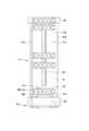
次に、供給ユニット31の詳細な構成について図2及び図3を参照して説明する。
図2は、供給ユニット31を示す平面図、図3は、供給ユニット31における投入口の周辺を示す斜視図である。
[Supply unit configuration]
Next, the detailed configuration of thesupply unit 31 will be described with reference to FIGS. 2 and 3.
FIG. 2 is a plan view showing thesupply unit 31, and FIG. 3 is a perspective view showing the periphery of the inlet in thesupply unit 31.

図2及び図3に示すように、供給ユニット31は、供給トレイ61と、供給側ガイドレール62と、供給側押し子機構63と、追加防止検知センサ64と、押し子確認センサ65と、を備えている。また、供給ユニット31は、原点センサ66(図6参照)を有している。 As shown in FIGS. 2 and 3, thesupply unit 31 includes asupply tray 61, a supplyside guide rail 62, a supplyside pusher mechanism 63, an additionalprevention detection sensor 64, and apusher confirmation sensor 65. I have. Further, thesupply unit 31 has an origin sensor 66 (see FIG. 6).

供給トレイ61は、平板状に形成されている。供給トレイ61は、検体ラック90が載置され、かつ検体ラック90が摺動する摺動面61aと、2つのガイド片61bとを有している。ガイド片61bは、摺動面61aにおける第1の方向Xの両端部から上下方向の上方に向けて立設されている。また、摺動面61aにおける第2の方向Yの一端部は、使用者によって検体ラック90が供給される検体ラック供給位置80(投入口31a)である。 Thesupply tray 61 is formed in a flat plate shape. Thesupply tray 61 has a slidingsurface 61a on which thesample rack 90 is placed and thesample rack 90 slides, and twoguide pieces 61b. Theguide piece 61b is erected from both ends of the slidingsurface 61a in the first direction X upward in the vertical direction. Further, one end of the slidingsurface 61a in the second direction Y is a sample rack supply position 80 (input port 31a) to which thesample rack 90 is supplied by the user.

摺動面61aにおける検体ラック供給位置80には、追加防止検知センサ64が設けられている。追加防止検知センサ64は、検体ラック供給位置80に供給された検体ラック90を検知する。 An additionalprevention detection sensor 64 is provided at the samplerack supply position 80 on the slidingsurface 61a. The additionalprevention detection sensor 64 detects thesample rack 90 supplied to the samplerack supply position 80.

追加防止検知センサ64としては、赤外線センサや、機械式のセンサや、光学センサ等その他各種のセンサを適用できるものである。 As the additionalprevention detection sensor 64, an infrared sensor, a mechanical sensor, an optical sensor, and other various sensors can be applied.

摺動面61aにおける第1の方向Xの略中央部には、供給側ガイドレール62が配置されている。供給側ガイドレール62は、第2の方向Yと平行に配置されている。供給側ガイドレール62は、摺動面61aにおける検体ラック供給位置80よりも第2の方向Yの他側から供給搬送部33まで延在している。すなわち、供給側ガイドレール62は、摺動面61aにおける検体ラック供給位置80には、配置されていない。また、供給側ガイドレール62には、検体ラック90の下端部に形成した係合溝部が摺動可能に係合する。そのため、検体ラック90が供給側ガイドレール62と係合している間は、後述する供給側押し子機構63の押し子部材72によって押圧されても検体ラック90が倒れることはない。 A supply-side guide rail 62 is arranged at a substantially central portion of the slidingsurface 61a in the first direction X. The supplyside guide rail 62 is arranged parallel to the second direction Y. The supply-side guide rail 62 extends from the other side of the samplerack supply position 80 on the slidingsurface 61a in the second direction Y to the supply /transport unit 33. That is, the supplyside guide rail 62 is not arranged at the samplerack supply position 80 on the slidingsurface 61a. Further, an engaging groove portion formed at the lower end of thesample rack 90 is slidably engaged with the supplyside guide rail 62. Therefore, while thesample rack 90 is engaged with the supplyside guide rail 62, thesample rack 90 does not fall even if pressed by thepusher member 72 of the supplyside pusher mechanism 63 described later.

供給側押し子機構63は、押し子駆動部71(図6参照)と、押し子部材72と、押し子支持部74とを有している。押し子部材72は、ヒンジ部73を介して押し子支持部74に支持されている。押し子支持部74は、ベルト部材やギア等からなる不図示の駆動機構に接続されており、第2の方向Yに沿って移動する。 The supply-side pusher mechanism 63 includes a pusher drive unit 71 (see FIG. 6), apusher member 72, and apusher support portion 74. Thepusher member 72 is supported by thepusher support portion 74 via thehinge portion 73. Thepusher support portion 74 is connected to a drive mechanism (not shown) composed of a belt member, a gear, or the like, and moves along the second direction Y.

また、押し子部材72は、略長方形をなす平板状に形成されている。押し子部材72は、ヒンジ部73及び押し子支持部74に支持されることで、摺動面61aにおける第1の方向Xの一端から他端にかけて跨ぐように摺動面61aの上方に配置される。押し子部材72における第2の方向Yの他側には、押圧部72aが設けられている。押圧部72aは、供給トレイ61に供給された検体ラック90における搬送方向の後方の背面に接触する。そして、押し子部材72は、押し子支持部74が第2の方向Yに沿って移動することで、検体ラック90を押圧部72aによって押圧し、第2の方向Yに沿って搬送する。 Further, thepusher member 72 is formed in a flat plate shape having a substantially rectangular shape. Thepusher member 72 is supported by thehinge portion 73 and thepusher support portion 74, and is arranged above the slidingsurface 61a so as to straddle the slidingsurface 61a from one end to the other end in the first direction X. To. Apressing portion 72a is provided on the other side of thepusher member 72 in the second direction Y. Thepressing portion 72a comes into contact with the rear back surface of thesample rack 90 supplied to thesupply tray 61 in the transport direction. Then, in thepusher member 72, thepusher support portion 74 moves along the second direction Y, so that thesample rack 90 is pressed by thepressing portion 72a and conveyed along the second direction Y.

図4は、押し子部材72が回動した状態を示す斜視図、図5は、検体ラック供給位置に検体ラックを供給する状態を示す斜視図である。
図3及び図4に示すように、押し子部材72は、ヒンジ部73によって上下方向に回動可能に支持されている。すなわち、押し子部材72は、図3に示すように、摺動面61aの上方を覆う搬送状態から、図4に示すように、ヒンジ部73と反対側の端部が上下方向の上方を向く開放状態にヒンジ部73を介して回動する。そのため、摺動面61aにおける検体ラック供給位置80の近傍の上方が開放される。これにより、図5に示すように、検体ラック供給位置80に検体ラック90を使用者が供給し易くなる。
FIG. 4 is a perspective view showing a state in which thepusher member 72 is rotated, and FIG. 5 is a perspective view showing a state in which the sample rack is supplied to the sample rack supply position.
As shown in FIGS. 3 and 4, thepusher member 72 is rotatably supported in the vertical direction by thehinge portion 73. That is, as shown in FIG. 3, thepusher member 72 is in a transport state that covers the upper part of the slidingsurface 61a, and as shown in FIG. 4, the end portion on the opposite side to thehinge portion 73 faces upward in the vertical direction. It rotates in the open state via thehinge portion 73. Therefore, the upper part of the slidingsurface 61a near the samplerack supply position 80 is opened. As a result, as shown in FIG. 5, the user can easily supply thesample rack 90 to the samplerack supply position 80.

また、供給トレイ61における検体ラック供給位置80の近傍には、押し子確認センサ65が設けられている。押し子確認センサ65は、検体ラック供給位置80に設けられた追加防止検知センサ64よりも第2の方向Yの一側、すなわち搬送方向の後方に配置されている。押し子確認センサ65は、供給側押し子機構63の押し子部材72を検知する。具体的には、押し子確認センサ65は、図3に示すように、押し子部材72が搬送状態の場合に、押し子部材72を検知する。そして、図4に示すように、押し子部材72が開放状態の場合には、押し子部材72は、押し子確認センサ65で検知されない。 Further, apusher confirmation sensor 65 is provided in the vicinity of the samplerack supply position 80 in thesupply tray 61. Thepusher confirmation sensor 65 is arranged on one side of the second direction Y, that is, behind the transport direction, with respect to the additionalprevention detection sensor 64 provided at the samplerack supply position 80. Thepusher confirmation sensor 65 detects thepusher member 72 of the supplyside pusher mechanism 63. Specifically, as shown in FIG. 3, thepusher confirmation sensor 65 detects thepusher member 72 when thepusher member 72 is in the conveyed state. Then, as shown in FIG. 4, when thepusher member 72 is in the open state, thepusher member 72 is not detected by thepusher confirmation sensor 65.

また、押し子確認センサ65の搬送方向、すなわち第2の方向Yにおける押し子部材72の有無を検知可能な範囲は、後述する原点センサ66の検知可能な範囲よりも広く設定されている。具体的には、追加防止検知センサ64によって検体ラック90を検知した場合において、押し子部材72が検体ラック90よりも搬送方向の後方に配置されて、且つ搬送状態の場合、押し子確認センサ65の検知可能な範囲は、押し子部材72を必ず検知できる範囲に設定されている。 Further, the transport direction of thepusher confirmation sensor 65, that is, the range in which the presence or absence of thepusher member 72 in the second direction Y can be detected is set wider than the detectable range of theorigin sensor 66 described later. Specifically, when thesample rack 90 is detected by the additionalprevention detection sensor 64, when thepusher member 72 is arranged behind thesample rack 90 in the transport direction and is in the transport state, thepusher confirmation sensor 65 The detectable range of is set to the range in which thepusher member 72 can always be detected.

押し子確認センサ65としては、赤外線センサや、機械式のセンサや、光学センサ等その他各種のセンサを適用できるものである。 As thepusher confirmation sensor 65, various other sensors such as an infrared sensor, a mechanical sensor, an optical sensor, and the like can be applied.

なお、本例の搬送装置30では、押し子確認センサ65の検知可能な範囲を広げる例を説明したが、これに限定されるものではない。押し子確認センサ65の検知可能な範囲を原点センサ66と同様の範囲に設定し、押し子部材72における第2の方向Y、すなわち搬送方向の長さを、長く設定してもよい。このとき、押し子部材72の搬送方向の長さは、追加防止検知センサ64によって検体ラック90を検知した場合において、押し子部材72が検体ラック90よりも搬送方向の後方に配置されて、且つ搬送状態の場合に、必ず押し子確認センサによって検知可能な長さに設定される。 In thetransport device 30 of this example, an example of expanding the detectable range of thepusher confirmation sensor 65 has been described, but the present invention is not limited to this. The detectable range of thepusher confirmation sensor 65 may be set to the same range as that of theorigin sensor 66, and the second direction Y of thepusher member 72, that is, the length in the transport direction may be set longer. At this time, the length of thepusher member 72 in the transport direction is such that when thesample rack 90 is detected by the additionalprevention detection sensor 64, thepusher member 72 is arranged behind thesample rack 90 in the transport direction. In the transport state, the length is always set so that it can be detected by the pusher confirmation sensor.

また、本例の搬送装置30では、押し子部材72の位置を検知する押し子確認センサ65として、押し子部材72の搬送状態と開放状態を検知するセンサを用いた例を説明したが、これに限定されるものではない。例えば、押し子部材72の搬送状態と開放状態を検知するセンサとは別に、押し子確認センサ65を設けてもよい。 Further, in thetransport device 30 of this example, an example in which a sensor for detecting the transport state and the open state of thepusher member 72 is used as thepusher confirmation sensor 65 for detecting the position of thepusher member 72 has been described. It is not limited to. For example, apusher confirmation sensor 65 may be provided separately from the sensor that detects the conveyed state and the open state of thepusher member 72.

1−5.検体ラック搬送装置の制御系の構成
次に、図6を参照して検体ラック搬送装置30の制御系の構成について説明する。
図6は、搬送装置30における供給ユニット31の制御系を示すブロック図である。
1-5. Configuration of Control System of Specimen Rack Transfer Device Next, the configuration of the control system of the samplerack transfer device 30 will be described with reference to FIG.
FIG. 6 is a block diagram showing a control system of thesupply unit 31 in thetransport device 30.

図6に示すように、搬送装置30は、制御部101と、報知部102を備えている。制御部101は、例えばCPU(Central Processing Unit)と、CPUが実行するプログラム等を記憶するためのROM(Read Only Memory)と、CPUの作業領域として使用されるRAM(Random Access Memory)と、を有する。 As shown in FIG. 6, thetransport device 30 includes acontrol unit 101 and anotification unit 102. Thecontrol unit 101 includes, for example, a CPU (Central Processing Unit), a ROM (Read Only Memory) for storing programs executed by the CPU, and a RAM (Random Access Memory) used as a work area of the CPU. Have.

制御部101は、供給ユニット31における原点センサ66、追加防止検知センサ64、押し子確認センサ65及び、供給側押し子機構63の押し子駆動部71に接続されている。そして、制御部101は、供給ユニット31を制御する。なお、制御部101は、搬送装置30における供給ユニット31以外の装置にも接続されており、搬送装置30全体を制御する。 Thecontrol unit 101 is connected to theorigin sensor 66, the additionprevention detection sensor 64, thepusher confirmation sensor 65, and thepusher drive unit 71 of the supplyside pusher mechanism 63 in thesupply unit 31. Then, thecontrol unit 101 controls thesupply unit 31. Thecontrol unit 101 is also connected to devices other than thesupply unit 31 in thetransfer device 30, and controls theentire transfer device 30.

押し子駆動部71は、制御部101によってその駆動が制御される。そして、押し子駆動部71が制御部101によって駆動すると、押し子部材72が第2の方向Yに沿って移動する。 The drive of thepusher drive unit 71 is controlled by thecontrol unit 101. Then, when thepusher drive unit 71 is driven by thecontrol unit 101, thepusher member 72 moves along the second direction Y.

原点センサ66は、供給トレイ61における供給側押し子機構63が検体ラック90の搬送を開始する位置、すなわち供給トレイ61の第2の方向Yの一端部に設けられている。原点センサ66が供給側押し子機構63の押し子支持部74及び押し子部材72を検知するとことで、制御部101は、押し子部材72が搬送を開始する位置に移動していると判断する。 Theorigin sensor 66 is provided at a position where the supply-side pusher mechanism 63 on thesupply tray 61 starts transporting thesample rack 90, that is, at one end of thesupply tray 61 in the second direction Y. When theorigin sensor 66 detects thepusher support portion 74 and thepusher member 72 of the supplyside pusher mechanism 63, thecontrol unit 101 determines that thepusher member 72 has moved to the position where the transfer starts. ..

なお、原点センサ66は、押し子部材72が搬送を開始する位置、すなわち押し子部材72の初期位置の原点を検知するものである。そして、原点に範囲がある場合、押し子部材72の搬送距離に誤差が生じ、検体ラック90の搬送に不具合が発生する。そのため、原点センサ66の検知可能な範囲は、極めて狭く設定されている。 Theorigin sensor 66 detects the origin of the position where thepusher member 72 starts transporting, that is, the initial position of thepusher member 72. If there is a range at the origin, an error will occur in the transport distance of thepusher member 72, and a problem will occur in the transport of thesample rack 90. Therefore, the detectable range of theorigin sensor 66 is set extremely narrow.

原点センサ66としては、赤外線センサや、機械式のセンサや、光学センサ等その他各種のセンサを適用できるものである。 As theorigin sensor 66, an infrared sensor, a mechanical sensor, an optical sensor, and various other sensors can be applied.

報知部102は、例えば画像を表示する表示部、光を出射する光源部、又は音を発するブザーなどから構成されている。そして、報知部102は、制御部101からの指令に基づいて使用者に各種情報を報知する。 Thenotification unit 102 includes, for example, a display unit that displays an image, a light source unit that emits light, a buzzer that emits sound, and the like. Then, thenotification unit 102 notifies the user of various information based on the command from thecontrol unit 101.

2.搬送装置における供給ユニットの動作
次に、供給ユニット31の動作例について図7〜図11を参照して説明する。
図7は、収容された検体ラック90を供給搬送部33に搬送する状態を示す斜視図である。
2. 2. Operation of the supply unit in the transfer device Next, an operation example of thesupply unit 31 will be described with reference to FIGS. 7 to 11.
FIG. 7 is a perspective view showing a state in which the housedsample rack 90 is transported to thesupply transport unit 33.

2−1.搬送時の動作
まず、供給ユニット31が検体ラック90を供給搬送部33に搬送する際の動作について説明する。
制御部101は、供給側押し子機構63を駆動し、押し子部材72を初期位置から第2の方向Yの他側に向けて移動させる。そのため、供給トレイ61に収容された検体ラック90は、押し子部材72で押圧されて、第2の方向Yの一側から他側に向けて搬送される。これにより、検体ラック90は、供給ユニット31の排出口31b(図1参照)から供給搬送部33に供給される。
2-1. Operation during transport First, the operation when thesupply unit 31 transports thesample rack 90 to thesupply transport unit 33 will be described.
Thecontrol unit 101 drives the supply-side pusher mechanism 63 to move thepusher member 72 from the initial position toward the other side in the second direction Y. Therefore, thesample rack 90 housed in thesupply tray 61 is pressed by thepusher member 72 and is conveyed from one side in the second direction Y toward the other side. As a result, thesample rack 90 is supplied to the supply /transport unit 33 from thedischarge port 31b (see FIG. 1) of thesupply unit 31.

図7に示すように、検体ラック90を搬送する際に、新たな検体ラック90が使用者によって検体ラック供給位置80に追加された場合、追加防止検知センサ64は、検体ラック供給位置80に供給された新たな検体ラック90を検知する。追加防止検知センサ64で検知した情報は、制御部101に送信される。そして、制御部101は、供給側押し子機構63による搬送動作を停止させると共に、報知部102を動作させる。次に、報知部102は、音や光等により、検体ラック供給位置80に検体ラック90が供給されたことを使用者に報知し、検体ラック供給位置80から検体ラック90を取り除くように使用者に伝える。 As shown in FIG. 7, when anew sample rack 90 is added to the samplerack supply position 80 by the user when thesample rack 90 is conveyed, the additionprevention detection sensor 64 supplies thesample rack 90 to the samplerack supply position 80. Thenew sample rack 90 is detected. The information detected by the additionalprevention detection sensor 64 is transmitted to thecontrol unit 101. Then, thecontrol unit 101 stops the transport operation by the supplyside pusher mechanism 63 and operates thenotification unit 102. Next, thenotification unit 102 notifies the user that thesample rack 90 has been supplied to the samplerack supply position 80 by sound, light, or the like, and the user removes thesample rack 90 from the samplerack supply position 80. Tell to.

そして、追加防止検知センサ64からの検知情報に基づいて、制御部101は、検体ラック供給位置80から検体ラック90が取り除かれたか否かを判断する。制御部101は、検体ラック供給位置80から検体ラック90が取り除かれたと判断した場合、報知部102を停止させて、供給側押し子機構63の搬送動作を再開させる。これにより、押し子部材72が初期位置に戻った際に、検体ラック供給位置80に載置された検体ラック90に押し子部材72が当接し、検体ラック90が倒れることを防ぐことができる。 Then, based on the detection information from the additionalprevention detection sensor 64, thecontrol unit 101 determines whether or not thesample rack 90 has been removed from the samplerack supply position 80. When thecontrol unit 101 determines that thesample rack 90 has been removed from the samplerack supply position 80, thecontrol unit 101 stops thenotification unit 102 and restarts the transport operation of the supplyside pusher mechanism 63. As a result, when thepusher member 72 returns to the initial position, thepusher member 72 comes into contact with thesample rack 90 placed at the samplerack supply position 80, and thesample rack 90 can be prevented from falling.

なお、検体ラック供給位置80に検体ラック90が追加された際に、供給側押し子機構63の搬送動作を停止される例を説明したが、これに限定されるものではない。例えば、検体ラック90の搬送時に新たな検体ラック90が検体ラック供給位置80に追加された場合、制御部101は、供給側押し子機構63の搬送動作を停止させずに、報知部102による報知動作のみ行うように制御してもよい。 Although the transfer operation of the supplyside pusher mechanism 63 is stopped when thesample rack 90 is added to the samplerack supply position 80, the present invention is not limited to this. For example, when anew sample rack 90 is added to the samplerack supply position 80 during transportation of thesample rack 90, thecontrol unit 101 notifies thenotification unit 102 without stopping the transfer operation of the supplyside pusher mechanism 63. It may be controlled to perform only the operation.

2−2.戻り動作
次に、使用者がスイッチ押下などの任意で押し子部材72を初期位置に戻す場合、又は供給トレイ61に検体ラック90が無いため押し子部材72が初期位置に自動で戻る場合の供給ユニット31の動作について図8〜図11を参照して説明する。
2-2. Return operation Next, when the user arbitrarily returns thepusher member 72 to the initial position by pressing a switch or the like, or when thepusher member 72 automatically returns to the initial position because there is nosample rack 90 in thesupply tray 61. The operation of theunit 31 will be described with reference to FIGS. 8 to 11.

図8及び図9は、原点センサ66がOFF、追加防止検知センサ64がONの状態を示す説明図である。 8 and 9 are explanatory views showing a state in which theorigin sensor 66 is OFF and the additionprevention detection sensor 64 is ON.

ここで、押し子部材72が初期位置まで戻る動作は、原点センサ66がONになるまで押し子部材72を移動させる動作である。そのため、原点センサ66がOFFの場合、制御部101は、押し子部材72が初期位置まで戻っていないと判断し、戻り動作を続行させる。上述したように、原点センサ66の検知可能な範囲は、極めて狭く設定されている。 Here, the operation of returning thepusher member 72 to the initial position is an operation of moving thepusher member 72 until theorigin sensor 66 is turned on. Therefore, when theorigin sensor 66 is OFF, thecontrol unit 101 determines that thepusher member 72 has not returned to the initial position, and continues the return operation. As described above, the detectable range of theorigin sensor 66 is set extremely narrow.

図8に示すように、押し子部材72が初期位置から搬送方向の前方に微少に移動した場合、原点センサ66の検知可能な範囲から押し子部材72が外れるため、原点センサ66の検知信号は、OFFとなる。なお、押し子部材72は、検体ラック供給位置80よりも搬送方向の前方に移動していない。また、図9に示すように、押し子部材72が検体ラック供給位置80よりも搬送方向の前方に位置している場合は、原点センサ66は、OFFとなる。 As shown in FIG. 8, when thepusher member 72 slightly moves forward from the initial position in the transport direction, thepusher member 72 is removed from the detectable range of theorigin sensor 66, so that the detection signal of theorigin sensor 66 is , OFF. Thepusher member 72 has not moved forward in the transport direction from the samplerack supply position 80. Further, as shown in FIG. 9, when thepusher member 72 is located in front of the samplerack supply position 80 in the transport direction, theorigin sensor 66 is turned off.

図8及び図9に示す状態で検体ラック供給位置80に検体ラック90が供給された場合、追加防止検知センサ64がONとなる。すなわち、図8及び図9に示す状態は、どちらも原点センサ66がOFFとなり追加防止検知センサ64がONとなる。 When thesample rack 90 is supplied to the samplerack supply position 80 in the state shown in FIGS. 8 and 9, the additionalprevention detection sensor 64 is turned on. That is, in both the states shown in FIGS. 8 and 9, theorigin sensor 66 is turned off and the additionalprevention detection sensor 64 is turned on.

なお、図9に示す状態では、押し子部材72は、検体ラック供給位置80に供給された検体ラック90よりも搬送方向の前方に位置しているため、押し子部材72が初期位置に戻る際に検体ラック90を倒すおそれがある。そのため、制御部101は、報知部102によって使用者に検体ラック供給位置80に追加された検体ラック90を取り除く旨を報知する必要がある。 In the state shown in FIG. 9, since thepusher member 72 is located in front of thesample rack 90 supplied to the samplerack supply position 80 in the transport direction, when thepusher member 72 returns to the initial position. There is a risk of knocking down thesample rack 90. Therefore, thecontrol unit 101 needs to notify the user by thenotification unit 102 that thesample rack 90 added to the samplerack supply position 80 will be removed.

これに対し、図8に示す状態では、押し子部材72は、検体ラック供給位置80に供給された検体ラック90よりも搬送方向の後方に位置しているため、検体ラック90が押し子部材72によって倒れることがない。このように、図8に示す状態は、正常な状態であるため、使用者に検体ラック供給位置80に追加された検体ラック90を取り除く旨を報知する必要がない。そのため、制御部101は、図8及び図9に示すような原点センサ66がOFFで、追加防止検知センサ64がONである状態を判別し、正常な状態で報知することを防ぐ必要がある。 On the other hand, in the state shown in FIG. 8, since thepusher member 72 is located behind thesample rack 90 supplied to the samplerack supply position 80 in the transport direction, thesample rack 90 is thepusher member 72. Will not fall over. As described above, since the state shown in FIG. 8 is a normal state, it is not necessary to notify the user that thesample rack 90 added to the samplerack supply position 80 is to be removed. Therefore, thecontrol unit 101 needs to determine the state in which theorigin sensor 66 as shown in FIGS. 8 and 9 is OFF and the additionalprevention detection sensor 64 is ON, and prevent the notification in a normal state.

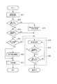
次に、上述した状態を考慮した押し子部材72の戻り動作について図10〜図11を参照して説明する。
図10は、押し子部材72の戻り動作を示すフローチャート、図11は、押し子部材72の戻り動作を模式的に示す説明図である。
Next, the return operation of thepusher member 72 in consideration of the above-mentioned state will be described with reference to FIGS. 10 to 11.
FIG. 10 is a flowchart showing the return operation of thepusher member 72, and FIG. 11 is an explanatory view schematically showing the return operation of thepusher member 72.

まず、使用者がスイッチを操作した場合や、供給トレイ61に検体ラック90が無い場合等において、供給ユニット31に対して押し子部材72の初期位置への戻り動作指令が行われると、制御部101は、初期化命令を行うと共に戻り動作を実行する(ステップS11)。次に、制御部101は、原点センサ66の検知信号がONであるかOFFであるかを判断する(ステップS12)。 First, when the user operates the switch, or when thesupply tray 61 does not have thesample rack 90, thecontrol unit 31 is instructed to return to the initial position of thepusher member 72. In 101, an initialization command is issued and a return operation is executed (step S11). Next, thecontrol unit 101 determines whether the detection signal of theorigin sensor 66 is ON or OFF (step S12).

ステップS12の処理において、制御部101は、原点センサ66の検知信号がONであると判断すると、原点センサ66の検知信号がOFFになるまで供給側押し子機構63を駆動させて押し子部材72を搬送方向の前方に向けて移動させる(ステップS13)。これにより、押し子部材72の初期位置の原点合わせを行う。そして、制御部101は、制御部101は、原点センサ66の検知信号がOFFになるまで押し子部材72が移動すると、供給側押し子機構63に戻り動作を実行させる(ステップS18)。 In the process of step S12, when thecontrol unit 101 determines that the detection signal of theorigin sensor 66 is ON, thecontrol unit 101 drives the supplyside pusher mechanism 63 until the detection signal of theorigin sensor 66 is turned OFF, and thepusher member 72. Is moved forward in the transport direction (step S13). As a result, the origin of the initial position of thepusher member 72 is aligned. Then, when thepusher member 72 moves until the detection signal of theorigin sensor 66 is turned off, thecontrol unit 101 returns to the supplyside pusher mechanism 63 to execute the operation (step S18).

これに対し、ステップS12の処理において、制御部101が原点センサ66の検知信号がOFFであると判断すると、制御部101は、追加防止検知センサ64の検知信号がONであるかOFFであるかを判断する(ステップS14)。ステップS14の処理において、制御部101が追加防止検知センサ64の検知信号がOFFであると判断、すなわち検体ラック供給位置80に検体ラック90が無いと判断すると、制御部101は、供給側押し子機構63に戻り動作を実行させる(ステップS18)。 On the other hand, in the process of step S12, when thecontrol unit 101 determines that the detection signal of theorigin sensor 66 is OFF, thecontrol unit 101 determines whether the detection signal of the additionalprevention detection sensor 64 is ON or OFF. Is determined (step S14). In the process of step S14, when thecontrol unit 101 determines that the detection signal of the additionprevention detection sensor 64 is OFF, that is, determines that there is nosample rack 90 at the samplerack supply position 80, thecontrol unit 101 determines that thesample rack 90 is not present. Themechanism 63 is returned to execute the operation (step S18).

これに対し、ステップS14の処理において、制御部101が追加防止検知センサ64の検知信号がONであると判断すると、検体ラック供給位置80に検体ラック90が供給されたと制御部101は、判断する。そして、制御部101は、押し子確認センサ65の検知信号がONであるかOFFであるかを判断する(ステップS15)。 On the other hand, in the process of step S14, when thecontrol unit 101 determines that the detection signal of the additionprevention detection sensor 64 is ON, thecontrol unit 101 determines that thesample rack 90 has been supplied to the samplerack supply position 80. .. Then, thecontrol unit 101 determines whether the detection signal of thepusher confirmation sensor 65 is ON or OFF (step S15).

ステップS15の処理において、制御部101が押し子確認センサ65の検知信号がONであると判断した場合、図11Aに示すように、押し子部材72は、検体ラック供給位置80よりも搬送方向の後方に位置していると判断できる。そのため、検体ラック供給位置80に検体ラック90が供給されていても押し子部材72は、検体ラック90よりも搬送方向の後方に位置している。そして、制御部101は、供給側押し子機構63に戻り動作を実行させる(ステップS18)。 When thecontrol unit 101 determines in the process of step S15 that the detection signal of thepusher confirmation sensor 65 is ON, thepusher member 72 is in the transport direction from the samplerack supply position 80 as shown in FIG. 11A. It can be determined that it is located behind. Therefore, even if thesample rack 90 is supplied to the samplerack supply position 80, thepusher member 72 is located behind thesample rack 90 in the transport direction. Then, thecontrol unit 101 returns to the supplyside pusher mechanism 63 to execute the operation (step S18).

また、ステップS15の処理において、制御部101が押し子確認センサ65の検知信号がOFFであると判断した場合、図11Bに示すように、押し子部材72は、検体ラック供給位置80よりも搬送方向の前方に位置していると考えられる。この状態で、押し子部材72が戻り動作を行うと、検体ラック供給位置80に供給された検体ラック90を倒すおそれがある。そのため、制御部101は、報知部102を動作させて警報を発報し、使用者に検体ラック供給位置80に供給された検体ラック90を取り除くように報知する(ステップS17)。 Further, in the process of step S15, when thecontrol unit 101 determines that the detection signal of thepusher confirmation sensor 65 is OFF, thepusher member 72 is conveyed from the samplerack supply position 80 as shown in FIG. 11B. It is considered to be located in front of the direction. If thepusher member 72 returns in this state, thesample rack 90 supplied to the samplerack supply position 80 may be knocked down. Therefore, thecontrol unit 101 operates thenotification unit 102 to issue an alarm, and notifies the user to remove thesample rack 90 supplied to the sample rack supply position 80 (step S17).

なお、ステップS17の処理により警報を発報した後に、使用者によって検体ラック90が取り除かれると、供給ユニット31は、ステップS11の処理に戻る。 When thesample rack 90 is removed by the user after issuing an alarm by the process of step S17, thesupply unit 31 returns to the process of step S11.

また、ステップS18における戻り動作が実行されて、押し子部材72が初期位置まで移動するまで、制御部101は、追加防止検知センサ64の検知信号がONであるかOFFであるかを判断する(ステップS19)。 Further, until the return operation in step S18 is executed and thepusher member 72 moves to the initial position, thecontrol unit 101 determines whether the detection signal of the additionprevention detection sensor 64 is ON or OFF (). Step S19).

ステップS19の処理において、制御部101が追加防止検知センサ64の検知信号がONであると判断、すなわち押し子部材72が初期位置に戻る動作を行っている際に、検体ラック供給位置80に検体ラック90が配置されたことが判断できる。 In the process of step S19, when thecontrol unit 101 determines that the detection signal of the additionprevention detection sensor 64 is ON, that is, when thepusher member 72 is performing the operation of returning to the initial position, the sample is returned to the samplerack supply position 80. It can be determined that therack 90 is arranged.

または、図11Cに示すように、押し子部材72の搬送方向の後方に配置されていた検体ラック90が、戻り動作を行う押し子部材72によって押圧されて、検体ラック供給位置80まで搬送されたと判断できる。上述したように、検体ラック供給位置80まで供給側ガイドレール62が延在していない。そのため、押し子部材72の戻り動作が継続されると、検体ラック90は、供給側ガイドレール62が途切れた検体ラック供給位置80で押し子部材72に押圧されて倒れるおそれがある。 Alternatively, as shown in FIG. 11C, thesample rack 90 arranged behind thepusher member 72 in the transport direction is pressed by thepusher member 72 that performs the return operation and is transported to the samplerack supply position 80. I can judge. As described above, the supplyside guide rail 62 does not extend to the samplerack supply position 80. Therefore, if the return operation of thepusher member 72 is continued, thesample rack 90 may be pressed by thepusher member 72 at the samplerack supply position 80 where the supplyside guide rail 62 is interrupted and may fall down.

したがって、ステップS19の処理において、制御部101が追加防止検知センサ64の検知信号がONであると判断すると、制御部101は、押し子駆動部71を停止させて、押し子部材72の戻り動作を停止させる(ステップS16)。これにより、検体ラック90は、押し子部材72によって搬送方向の後方に押圧されることがなくなる。そして、制御部101は、報知部102を動作させて警報を発報し、使用者に検体ラック供給位置80に供給された検体ラック90を取り除くように報知する(ステップS17)。 Therefore, in the process of step S19, when thecontrol unit 101 determines that the detection signal of the additionprevention detection sensor 64 is ON, thecontrol unit 101 stops thepusher drive unit 71 and returns thepusher member 72. Is stopped (step S16). As a result, thesample rack 90 is not pressed backward in the transport direction by thepusher member 72. Then, thecontrol unit 101 operates thenotification unit 102 to issue an alarm, and notifies the user to remove thesample rack 90 supplied to the sample rack supply position 80 (step S17).

なお、ステップS17の処理により警報を発報した後に、使用者によって検体ラック90が取り除かれると、供給ユニット31は、ステップS11の処理に戻る。 When thesample rack 90 is removed by the user after issuing an alarm by the process of step S17, thesupply unit 31 returns to the process of step S11.

また、ステップS19の処理において、制御部101が追加防止検知センサ64の検知信号がOFFであると判断すると、制御部101は、原点センサ66の検知信号がONであるかOFFであるか判断する(ステップS20)。ステップS20の処理において、制御部101が原点センサ66の検知信号がOFFであると判断した場合、押し子部材72は、初期位置まで戻っていないと判断できる。そのため、制御部101は、ステップS18の処理に戻り押し子部材72の戻り動作を継続させる。 Further, in the process of step S19, when thecontrol unit 101 determines that the detection signal of the additionprevention detection sensor 64 is OFF, thecontrol unit 101 determines whether the detection signal of theorigin sensor 66 is ON or OFF. (Step S20). When thecontrol unit 101 determines in the process of step S20 that the detection signal of theorigin sensor 66 is OFF, it can be determined that thepusher member 72 has not returned to the initial position. Therefore, thecontrol unit 101 returns to the process of step S18 and continues the return operation of thepusher member 72.

これに対して、ステップS20の処理において、制御部101が原点センサ66の検知信号がONであると判断した場合、押し子部材72は、初期位置まで戻っていると判断できる。これにより、供給ユニット31における押し子部材72の戻り動作が完了する。 On the other hand, in the process of step S20, when thecontrol unit 101 determines that the detection signal of theorigin sensor 66 is ON, it can be determined that thepusher member 72 has returned to the initial position. As a result, the return operation of thepusher member 72 in thesupply unit 31 is completed.

上述したように、本例の搬送装置30によれば、検体ラック供給位置80に設けた追加防止検知センサ64により、検体ラック供給位置80に追加された検体ラック90を検知することができる。これにより、押し子部材72が戻り動作を行う際に、検体ラック供給位置80に検体ラック90が追加されたことを検知することができ、戻り動作を行う押し子部材72によって追加された検体ラック90が倒れることを防ぐことができる。 As described above, according to thetransport device 30 of this example, thesample rack 90 added to the samplerack supply position 80 can be detected by the additionalprevention detection sensor 64 provided at the samplerack supply position 80. As a result, when thepusher member 72 performs the return operation, it is possible to detect that thesample rack 90 has been added to the samplerack supply position 80, and the sample rack added by thepusher member 72 that performs the return operation can be detected. It is possible to prevent the 90 from falling over.

さらに、ステップS15の工程において、押し子確認センサ65の検知信号を用いることで、図8及び図9に示す状態を判別することができる。その結果、追加防止検知センサ64がONになっている図8に示すような押し子部材72が検体ラック90よりも搬送方向の後方に位置している状態で、誤って警報が発報されることを防ぐことができ、警報が発報される精度を向上させることができる。 Further, in the step S15, the state shown in FIGS. 8 and 9 can be determined by using the detection signal of thepusher confirmation sensor 65. As a result, an alarm is erroneously issued while thepusher member 72 as shown in FIG. 8 in which the additionalprevention detection sensor 64 is ON is located behind thesample rack 90 in the transport direction. This can be prevented and the accuracy with which the alarm is issued can be improved.

なお、本発明は上述しかつ図面に示した実施の形態に限定されるものではなく、特許請求の範囲に記載した発明の要旨を逸脱しない範囲内で種々の変形実施が可能である。例えば、自動分析装置として、血液や尿の生体試料の分析に用いられる生化学分析装置に適用した例を説明したが、これに限定されるものでなく、水質や、食品等のその他各種の分析を行う装置に適用することができるものである。また、自動分析装置としては、例えば、被検体の抗原抗体反応などの免疫分析を行う免疫分析装置を適用してもよい。 The present invention is not limited to the embodiments described above and shown in the drawings, and various modifications can be made without departing from the gist of the invention described in the claims. For example, an example of application to a biochemical analyzer used for analysis of biological samples of blood and urine as an automatic analyzer has been described, but the present invention is not limited to this, and various other analyzes such as water quality and foods are analyzed. It can be applied to the device that performs the above. Further, as the automatic analyzer, for example, an immunoanalyzer that performs immunoanalysis such as an antigen-antibody reaction of a subject may be applied.

1…生化学分析装置(自動分析装置)、 30…検体ラック搬送装置、 31…供給ユニット、 32…回収ユニット、 52…回収トレイ、 61…供給トレイ(トレイ)、 61a…摺動面、 62…供給側ガイドレール、 63…供給側押し子機構、 64…追加防止検知センサ、 65…押し子確認センサ、 66…原点センサ、 71…押し子駆動部、 72…押し子部材、 73…ヒンジ部、 74…押し子支持部、 80…検体ラック供給位置、 90…検体ラック、 100…生化学分析システム、 101…制御部、 102…報知部、X…第1の方向、 Y…第2の方向 1 ... Biochemical analyzer (automatic analyzer), 30 ... Specimen rack transfer device, 31 ... Supply unit, 32 ... Recovery unit, 52 ... Recovery tray, 61 ... Supply tray (tray), 61a ... Sliding surface, 62 ... Supply side guide rail, 63 ... Supply side pusher mechanism, 64 ... Additional prevention detection sensor, 65 ... Pusher confirmation sensor, 66 ... Origin sensor, 71 ... Pusher drive unit, 72 ... Pusher member, 73 ... Hinge part, 74 ... Pusher support, 80 ... Specimen rack supply position, 90 ... Specimen rack, 100 ... Biochemical analysis system, 101 ... Control unit, 102 ... Notification unit, X ... First direction, Y ... Second direction

Claims (6)

Translated fromJapanese
複数の検体容器を収容する検体ラックが載置され、前記検体ラックが供給される検体ラック供給位置を有するトレイと、
前記検体ラックを押圧して搬送する押し子部材と、
前記押し子部材を搬送方向に沿って移動させる駆動部と、
前記駆動部の駆動を制御する制御部と、
前記検体ラック供給位置において前記検体ラックの有無を検知する検知センサと、
前記制御部により制御されて使用者に情報を報知する報知部と、を備え、
前記制御部は、
前記押し子部材を前記検体ラックの搬送を開始する位置である初期位置から前記搬送方向に沿って移動させた際に、前記検知センサから送信される情報に基づいて、前記報知部の報知及び前記駆動部の駆動のうち少なくとも一方を制御する
検体ラック搬送装置。
A tray on which a sample rack for accommodating a plurality of sample containers is placed and having a sample rack supply position to which the sample rack is supplied, and a tray
A pusher member that presses and conveys the sample rack,
A drive unit that moves the pusher member along the transport direction,
A control unit that controls the drive of the drive unit,
A detection sensor that detects the presence or absence of the sample rack at the sample rack supply position,
A notification unit that is controlled by the control unit to notify the user of information is provided.
The control unit
When the pusher member is moved along the transport direction from the initial position where the transport of the sample rack is started, the notification of the notification unit and the notification of the notification unit are based on the information transmitted from the detection sensor. A sample rack transfer device that controls at least one of the drives of the drive unit.
前記検知センサは、
前記押し子部材を前記検体ラックの搬送を開始する位置である初期位置から前記搬送方向に沿って移動させた際に、前記検体ラック供給位置に新たな検体ラックが追加された場合、前記検体ラック供給位置に追加された前記新たな検体ラックを検知し、検知した情報を前記制御部に送信する
請求項1に記載の検体ラック搬送装置。
The detection sensor is
When a new sample rack is added to the sample rack supply position when the pusher member is moved along the transport direction from the initial position where the transport of the sample rack is started, the sample rack The sample rack transfer device according to claim 1, wherein the new sample rack added to the supply position is detected, and the detected information is transmitted to the control unit.
前記制御部は、前記押し子部材を前記検体ラックの搬送を開始する位置である初期位置から前記搬送方向に沿って移動させた際に、前記検知センサから前記検体ラック供給位置に前記新たな検体ラックが追加されたことを検知した情報を受信すると、前記報知部の報知及び前記駆動部の駆動のうち少なくとも一方を制御し、前記報知部によって前記検体ラック供給位置に前記検体ラックが供給されたことを使用者に報知させる、又は前記駆動部及び前記押し子部材による搬送動作を停止させる
請求項2に記載の検体ラック搬送装置。
When the pusher member is moved along the transport direction from the initial position where the transport of the sample rack is started, the control unit moves the new sample from the detection sensor to the sample rack supply position. Upon receiving the information that detected that the rack was added, at least one of the notification of the notification unit and the drive of the drive unit was controlled, and the sample rack was supplied to the sample rack supply position by the notification unit. The sample rack transport device according to claim 2, wherein the user is notified of the fact, or the transport operation by the drive unit and the pusher member is stopped.
前記制御部は、前記検知センサからの検知情報に基づいて、前記検体ラック供給位置から前記新たな検体ラックが取り除かれたか否かを判断する
請求項3に記載の検体ラック搬送装置。
The sample rack transport device according to claim 3, wherein the control unit determines whether or not the new sample rack has been removed from the sample rack supply position based on the detection information from the detection sensor.
前記制御部は、
前記押し子部材を前記検体ラックの搬送を開始する位置である初期位置から前記搬送方向に沿って移動させた際に、前記検知センサから前記検体ラック供給位置に前記新たな検体ラックが追加されたことを検知した情報を受信すると、前記駆動部を制御し、前記駆動部及び前記押し子部材による搬送動作を停止させ、
前記検知センサからの検知情報に基づいて、前記検体ラック供給位置から前記新たな検体ラックが取り除かれたか否かを判断し、
前記検体ラック供給位置から前記新たな検体ラックが取り除かれたと判断した場合、前記駆動部を制御し、前記駆動部及び前記押し子部材による搬送動作を再開させる
請求項2に記載の検体ラック搬送装置。
The control unit
When the pusher member was moved along the transport direction from the initial position where the transport of the sample rack was started, the new sample rack was added to the sample rack supply position from the detection sensor. Upon receiving the detected information, the drive unit is controlled to stop the transport operation by the drive unit and the pusher member.
Based on the detection information from the detection sensor, it is determined whether or not the new sample rack has been removed from the sample rack supply position.
The sample rack transfer device according to claim 2, wherein when it is determined that the new sample rack has been removed from the sample rack supply position, the drive unit is controlled to restart the transfer operation by the drive unit and the pusher member. ..
検体容器の内に収容された検体の分析を行う自動分析装置と、
前記検体容器が収容された検体ラックを搬送する検体ラック搬送装置と、を備え、
前記検体ラック搬送装置は、
前記検体ラックが載置され、前記検体ラックが供給される検体ラック供給位置を有するトレイと、
前記検体ラックを押圧して搬送する押し子部材と、
前記押し子部材を搬送方向に沿って移動させる駆動部と、
前記駆動部の駆動を制御する制御部と、
前記検体ラック供給位置において前記検体ラックの有無を検知する検知センサと、
前記制御部により制御されて使用者に情報を報知する報知部と、を備え、
前記制御部は、
前記押し子部材を前記検体ラックの搬送を開始する位置である初期位置から前記搬送方向に沿って移動させた際に、前記検知センサから送信される情報に基づいて、前記報知部の報知及び前記駆動部の駆動のうち少なくとも一方を制御する
自動分析システム。
An automatic analyzer that analyzes the sample contained in the sample container,
A sample rack transfer device for transporting a sample rack containing the sample container is provided.
The sample rack transfer device is
A tray on which the sample rack is placed and a tray having a sample rack supply position to which the sample rack is supplied,
A pusher member that presses and conveys the sample rack,
A drive unit that moves the pusher member along the transport direction,
A control unit that controls the drive of the drive unit,
A detection sensor that detects the presence or absence of the sample rack at the sample rack supply position,
A notification unit that is controlled by the control unit to notify the user of information is provided.
The control unit
When the pusher member is moved along the transport direction from the initial position where the transport of the sample rack is started, the notification of the notification unit and the notification of the notification unit are based on the information transmitted from the detection sensor. An automatic analysis system that controls at least one of the drives of the drive unit.
JP2020107174A2016-09-292020-06-22 Specimen rack transfer device and automatic analysis systemActiveJP6976643B2 (en)

Priority Applications (1)

Application NumberPriority DateFiling DateTitle
JP2020107174AJP6976643B2 (en)2016-09-292020-06-22 Specimen rack transfer device and automatic analysis system

Applications Claiming Priority (2)

Application NumberPriority DateFiling DateTitle
JP2016192022AJP6746454B2 (en)2016-09-292016-09-29 Sample rack transporter and automatic analysis system
JP2020107174AJP6976643B2 (en)2016-09-292020-06-22 Specimen rack transfer device and automatic analysis system

Related Parent Applications (1)

Application NumberTitlePriority DateFiling Date
JP2016192022ADivisionJP6746454B2 (en)2016-09-292016-09-29 Sample rack transporter and automatic analysis system

Publications (2)

Publication NumberPublication Date
JP2020160084Atrue JP2020160084A (en)2020-10-01
JP6976643B2 JP6976643B2 (en)2021-12-08

Family

ID=72643052

Family Applications (1)

Application NumberTitlePriority DateFiling Date
JP2020107174AActiveJP6976643B2 (en)2016-09-292020-06-22 Specimen rack transfer device and automatic analysis system

Country Status (1)

CountryLink
JP (1)JP6976643B2 (en)

Citations (4)

* Cited by examiner, † Cited by third party
Publication numberPriority datePublication dateAssigneeTitle
JP2010156624A (en)*2008-12-272010-07-15Sysmex CorpTransportation apparatus and specimen analyzer using the same
JP2010276514A (en)*2009-05-292010-12-09Sysmex Corp Sample processing equipment
CN102360019A (en)*2011-08-162012-02-22内蒙古科慧生物科技有限责任公司Sample rack transmitting and promoting apparatus for automatic chemiluminescence analyzer
JP2014016360A (en)*2008-11-172014-01-30Sysmex CorpSpecimen analyzer and specimen rack conveyance method

Patent Citations (4)

* Cited by examiner, † Cited by third party
Publication numberPriority datePublication dateAssigneeTitle
JP2014016360A (en)*2008-11-172014-01-30Sysmex CorpSpecimen analyzer and specimen rack conveyance method
JP2010156624A (en)*2008-12-272010-07-15Sysmex CorpTransportation apparatus and specimen analyzer using the same
JP2010276514A (en)*2009-05-292010-12-09Sysmex Corp Sample processing equipment
CN102360019A (en)*2011-08-162012-02-22内蒙古科慧生物科技有限责任公司Sample rack transmitting and promoting apparatus for automatic chemiluminescence analyzer

Also Published As

Publication numberPublication date
JP6976643B2 (en)2021-12-08

Similar Documents

PublicationPublication DateTitle
JP6573524B2 (en) Sample rack transport apparatus and automatic analysis system
JP6573547B2 (en) Sample rack transport apparatus, automatic analysis system, and sample rack recovery method for sample rack transport apparatus
CN102023222B (en)Sample processing apparatus and sample rack transporting method
CN107923925B (en)Inspection rack conveying device and automatic analysis system
JP6549983B2 (en) Sample rack transport device and automatic analysis system
JP6472961B2 (en) Sample rack transport unit and automatic analysis system
JP6746454B2 (en) Sample rack transporter and automatic analysis system
JP2021081213A (en)Blood coagulation analyzer and cleaning method of dispensing nozzle
JP5903054B2 (en) Automatic analyzer
JP6429753B2 (en) Automatic analyzer and automatic analysis method
JP6976643B2 (en) Specimen rack transfer device and automatic analysis system
JP5258090B2 (en) Automatic analyzer
JP2020118561A (en)Reagent bottle storage unit and automatic analyzer
JP7179928B2 (en) automatic analyzer
JP6929636B2 (en) Automatic analyzer
JP5738696B2 (en) Biochemical analyzer
JP2010019808A (en)Automatic analyzer
JP7123548B2 (en) automatic analyzer
JP7054616B2 (en) Automatic analyzer
JP5261285B2 (en) Automatic analyzer and transfer device
JP7054647B2 (en) Dispensing unit and automatic analyzer
US10908174B2 (en)Automatic analyzing apparatus
JPS63503245A (en) Diluent carryover control
CN115728500A (en)Automatic analyzer

Legal Events

DateCodeTitleDescription
A621Written request for application examination

Free format text:JAPANESE INTERMEDIATE CODE: A621

Effective date:20200625

A977Report on retrieval

Free format text:JAPANESE INTERMEDIATE CODE: A971007

Effective date:20210524

A131Notification of reasons for refusal

Free format text:JAPANESE INTERMEDIATE CODE: A131

Effective date:20210601

A521Request for written amendment filed

Free format text:JAPANESE INTERMEDIATE CODE: A523

Effective date:20210713

TRDDDecision of grant or rejection written
A01Written decision to grant a patent or to grant a registration (utility model)

Free format text:JAPANESE INTERMEDIATE CODE: A01

Effective date:20210803

R155Notification before disposition of declining of application

Free format text:JAPANESE INTERMEDIATE CODE: R155

A61First payment of annual fees (during grant procedure)

Free format text:JAPANESE INTERMEDIATE CODE: A61

Effective date:20211108

R150Certificate of patent or registration of utility model

Ref document number:6976643

Country of ref document:JP

Free format text:JAPANESE INTERMEDIATE CODE: R150


[8]ページ先頭

©2009-2025 Movatter.jp