JP2020156607A - Control device, robot, control method, and program - Google Patents
Control device, robot, control method, and programDownload PDFInfo
- Publication number
- JP2020156607A JP2020156607AJP2019056936AJP2019056936AJP2020156607AJP 2020156607 AJP2020156607 AJP 2020156607AJP 2019056936 AJP2019056936 AJP 2019056936AJP 2019056936 AJP2019056936 AJP 2019056936AJP 2020156607 AJP2020156607 AJP 2020156607A
- Authority
- JP
- Japan
- Prior art keywords
- robot
- state
- target
- sensor
- microphone
- Prior art date
- Legal status (The legal status is an assumption and is not a legal conclusion. Google has not performed a legal analysis and makes no representation as to the accuracy of the status listed.)
- Granted
Links
Images


Classifications
- B—PERFORMING OPERATIONS; TRANSPORTING
- B25—HAND TOOLS; PORTABLE POWER-DRIVEN TOOLS; MANIPULATORS
- B25J—MANIPULATORS; CHAMBERS PROVIDED WITH MANIPULATION DEVICES
- B25J9/00—Programme-controlled manipulators
- B25J9/16—Programme controls
- B25J9/1602—Programme controls characterised by the control system, structure, architecture
- B—PERFORMING OPERATIONS; TRANSPORTING
- B25—HAND TOOLS; PORTABLE POWER-DRIVEN TOOLS; MANIPULATORS
- B25J—MANIPULATORS; CHAMBERS PROVIDED WITH MANIPULATION DEVICES
- B25J11/00—Manipulators not otherwise provided for
- B25J11/0005—Manipulators having means for high-level communication with users, e.g. speech generator, face recognition means
Landscapes
- Engineering & Computer Science (AREA)
- Robotics (AREA)
- Mechanical Engineering (AREA)
- Automation & Control Theory (AREA)
- Health & Medical Sciences (AREA)
- Audiology, Speech & Language Pathology (AREA)
- General Health & Medical Sciences (AREA)
- Human Computer Interaction (AREA)
- Toys (AREA)
- Manipulator (AREA)
- User Interface Of Digital Computer (AREA)
Abstract
Translated fromJapaneseDescription
Translated fromJapanese本発明は、人が保持することが可能で、人に関する情報を取得するロボットに適用される制御装置、制御方法およびプログラムに関する。 The present invention relates to control devices, control methods and programs that can be held by a person and applied to a robot that acquires information about the person.
近年、癒やしを求める人のために、ペットに代わるロボットが提案されている。例えば、特許文献1には、ユーザが抱っこできるように構成されたロボットが開示されている。特許文献1の自律行動型ロボットは、その内部にマイクロフォンが、眼の部分にモニタが、それぞれ設けられており、マイクロフォンで取得したユーザの音声に応じて眼画像を生成するとともに、生成した眼画像をこのモニタに表示することによって、ロボットの目の表現力を高めるようにしている。 In recent years, robots that replace pets have been proposed for those seeking healing. For example,
特許文献1の自律行動型ロボットのような抱っこ可能なロボットでは、ユーザに保持されているロボットの保持状態によっては、ロボットの内部のマイクロフォンでユーザの音声を適切に検出することができないおそれがある。このような不具合は、マイクロフォンでユーザの音声を検出する場合に限らず、他の適当なユーザに関する情報、例えば、カメラでユーザの表情を検出するような場合にも、同様に当てはまる。 In a huggable robot such as the autonomous action robot of
本発明は、上述のような事情に鑑みてなされたもので、所定の対象によるロボットの保持状態によらず、所定の対象に関する情報を適切に取得可能にすることを目的とする。 The present invention has been made in view of the above circumstances, and an object of the present invention is to make it possible to appropriately acquire information on a predetermined object regardless of the holding state of the robot by the predetermined object.
上記目的を達成するため、本発明に係る制御装置は、
ロボットに設けられ、所定の対象に関する情報を検出するための対象センサと、
前記所定の対象による前記ロボットの保持状態を判定する第1判定手段と、
前記第1判定手段により判定された前記ロボットの保持状態に応じて、前記対象センサの検出状態又は検出結果を制御する制御手段と、
を備えることを特徴とする。In order to achieve the above object, the control device according to the present invention is
A target sensor provided on the robot to detect information about a predetermined target,
A first determination means for determining the holding state of the robot by the predetermined object, and
A control means for controlling the detection state or the detection result of the target sensor according to the holding state of the robot determined by the first determination means.
It is characterized by having.
本発明によれば、所定の対象によるロボットの保持状態によらず、所定の対象に関する情報を適切に取得することができる。 According to the present invention, information on a predetermined object can be appropriately acquired regardless of the holding state of the robot by the predetermined object.
以下、本発明の実施の形態について、図面を参照して説明する。なお、図中同一または相当する部分には同一の符号を付す。 Hereinafter, embodiments of the present invention will be described with reference to the drawings. In the figure, the same or corresponding parts are designated by the same reference numerals.
実施の形態.
図1Aは、本発明の実施の形態に係るロボットの概略構成を示す正面図である。図1Bは、図1Aに示されるロボットの背面図である。ロボット1は、その前面に配置された前面マイクロフォン2、その背面に配置された背面マイクロフォン3、スピーカ4、および複数の接触センサ5を備える。例えば、前面マイクロフォン2は指向性を有しており、背面マイクロフォン3は指向性を有していない(無指向性)。ロボット1は、前面マイクロフォン2または背面マイクロフォン3で、所定の対象の発話を捉え、発話に応じた応答文を生成してスピーカ4から音声で出力する。Embodiment.
FIG. 1A is a front view showing a schematic configuration of a robot according to an embodiment of the present invention. FIG. 1B is a rear view of the robot shown in FIG. 1A. The
ロボット1は、自装置の外部に存在する所定の対象からの呼び掛け、接触等の外部からの刺激に反応して、様々に動作する。これによって、ロボット1は、所定の対象とコミュニケーションをとり、所定の対象と交流することができる。所定の対象とは、ロボット1の外部に存在し、且つ、ロボット1とコミュニケーションおよび交流する相手となる対象である。所定の対象には、例えば、ロボット1の所有者であるユーザ、ユーザの周囲の人間(ユーザの親近者もしくは友人等)、および他のロボット等が含まれる。所定の対象は、コミュニケーション対象、コミュニケーション相手、交流対象、交流相手等とも言うことができる。 The
ロボット1は、所定の対象と会話することを目的としている。ロボット1は、人間が抱っこできる大きさと重さである。ロボット1は、図1Aおよび図1Bに示される以外に、加速度センサおよびジャイロセンサを備える。 The
家庭の中で共に過ごすコミュニケーションデバイスには、ちょっとした音に過剰に反応しない、不要な音に反応しない鈍感さと、話かけている人の声には機敏に反応する正確さを求められる。そのため、従来のコミュニケーションデバイスでは、特定のキーワードや意味ある会話かを判定し、それまではマイク・音検出の制御や内部処理の変更で対応している。しかし、必ず決められたキーワードを初めに発話しなければならない煩わしさや、常に内部処理を行わなければならない等の短所がある。 Communication devices that we spend time with at home are required to be insensitive to not overreacting to small sounds and not to respond to unnecessary sounds, and to be accurate enough to respond quickly to the voice of the person speaking. Therefore, in the conventional communication device, it is determined whether it is a specific keyword or a meaningful conversation, and until then, the control of microphone / sound detection and the change of internal processing are used. However, there are disadvantages such as the inconvenience of having to speak a fixed keyword first and the need to always perform internal processing.
そこで、実施の形態の制御装置は、接触センサ5、加速度センサ、ジャイロセンサで検出したデータから、ロボット1の状態を判定し、判定した状態に応じて、前面マイクロフォン2および背面マイクロフォン3の検出状態を制御する。 Therefore, the control device of the embodiment determines the state of the
図2は、実施の形態に係るロボットの制御装置の機能構成を示すブロック図である。制御装置10は、前面マイクロフォン2、背面マイクロフォン3、接触センサ5、加速度センサ6、ジャイロセンサ7、音声取得部11、音声認識部12、マイク制御部13、状態判定部14、音声出力部15、および、応答制御部16を備える。制御装置10は、例えば人の顔を認識するための撮像装置(カメラ)を備えていてもよい。 FIG. 2 is a block diagram showing a functional configuration of the robot control device according to the embodiment. The
音声取得部11は、所定の対象によって前面マイクロフォン2または背面マイクロフォン3から入力された音声信号を、所定の周波数でサンプリングし、A−D変換して音声データを生成する。音声取得部11は、音声データを音声認識部12に送る。 The
音声認識部12は、音声データから、発声内容を示す文字列に変換して、発話された文の意味を解析する。音声認識部12は、解析した文の意味を表す情報を、応答制御部16に送る。応答制御部16は、文の意味を表す情報に応じて、多数の応答文を記憶するデータベースを検索して、発話した話者ごとに発話された内容に適した応答文を取得し、音声出力部15に送る。音声出力部15は、応答制御部16から指示された応答文を、周知の音声合成技術を用いて音声データに変換し、変換した音声データに基づく制御信号をスピーカ4に入力することによって、所定の対象に応答文を音声で出力する。 The
状態判定部14は、接触センサ5、加速度センサ6およびジャイロセンサ7から、それぞれが検出したデータを入力する。接触センサ5は、例えば、静電容量の変化で所定の対象が接触しているか否かを検出する。加速度センサ6は、例えば、静電容量型またはピエゾ抵抗型の3軸加速度センサ6で、ロボット1の3軸の加速度を検出する。3軸の加速度は、互いに直交する3方向の座標軸(X,Y,Z)それぞれの方向の加速度である。ジャイロセンサ7は、例えば、圧電振動子またはシリコン振動子を用いて、ロボット1の角速度を検出する。 The state determination unit 14 inputs data detected by each of the
状態判定部14は、接触センサ5、加速度センサ6およびジャイロセンサ7による検出信号に基づいて、ロボット1の状態を判定する。ここで、ロボット1の状態とは、所定の対象によって持ち上げられた状態、抱っこされた状態、手、膝もしくは体の上に置かれた状態、撫でられている状態、および、静止して触られていない状態、などである。状態判定部14は、ロボット1の保持状態を判定する第1判定手段として機能し、また、ロボット1が撫でられているかどうかを判定する第2判定手段として機能する。 The state determination unit 14 determines the state of the
マイク制御部13は、状態判定部14で判定したロボット1の状態に応じて、前面マイクロフォン2および背面マイクロフォン3の検出状態を制御する。ここで、検出状態とは、検出のオン/オフや、検出感度のレベルを指す。マイク制御部13は、例えば、前面マイクロフォン2および背面マイクロフォン3それぞれの感度を切り換えたり、オン/オフを切り換えたりする。マイク制御部13は、対象センサである前面マイクロフォン2および背面マイクロフォン3の検出状態を制御する制御手段として機能する。なお、前面マイクロフォン2および背面マイクロフォン3の感度は、それらで検出される音声信号のレベルを決定するので、前面マイクロフォン2および背面マイクロフォン3の感度を制御することは、それらの検出状態を制御する手段の1つである。 The
制御装置10は、I/Oインターフェース、CPU(Central Processing Unit)、ROM(Read Only Memory)およびRAM(Random Access Memory)を備える。CPUは、例えばマイクロプロセッサ等であって、様々な処理や演算を実行する中央演算処理部である。制御装置10は、ROMに記憶されている制御プログラムを読み出して、RAMをワークメモリとして用いながら、CPUで制御プログラムを実行することによって、前面マイクロフォン2及び背面マイクロフォン3の検出状態と、ロボット1の動作とを制御する。 The
次に、図3を参照しながら、制御装置10によって実行されるマイク・応答制御処理について説明する。マイク・応答制御処理は、ロボット1の制御を開始すると起動され、繰り返し実行される。まず、状態判定部14は、接触センサ5から接触データを、加速度センサ6から加速度データを、ジャイロセンサ7から角速度データをそれぞれ取得する(ステップS301)。状態判定部14は、接触データ、加速度データおよび角速度データから、ロボット1が前述のような状態のいずれにあるかを判定する(ステップS302)。この状態判定処理については後述する。 Next, the microphone / response control process executed by the
状態判定部14は、ステップS302における状態判定による判定結果に基づいて、ロボット1の現在の状態が直前の状態から変化したか否かを判別する(ステップS303)。ロボット1の状態が変化しているとき(ステップS303;Y)には、前面マイクロフォン2および背面マイクロフォン3の検出状態をロボット1の現在の状態に基づいて制御して(ステップS304)、直前の状態を現在の状態に置き換える(ステップS305)。そして、前面マイクロフォン2および背面マイクロフォン3の少なくとも1つから音声信号を入力し、音声信号から音声データを取得する(ステップS306)。ロボット1の現在の状態が直前の状態から変化していなければ(ステップS303;N)、マイク制御も状態の置き換えもせずに、音声データを取得する(ステップS306)。 The state determination unit 14 determines whether or not the current state of the
音声取得部11は、音声データを取得した(ステップS306)のち、取得した音声データのレベルが設定値より小さいか否かを判別する(ステップS307)。音声データのレベルが設定値より小さいとき(ステップS307;Y)、所定の対象が発話していないと判定して、ステップS301に戻り、接触データ取得から繰り返す。 After acquiring the voice data (step S306), the
一方、ステップS307で音声データのレベルが設定値以上であるとき(ステップS307;N)には、所定の対象が発話したと判定して、音声取得部11で取得した(ステップS306で取得した)音声データを、音声認識部12で音声認識する(ステップS308)。応答制御部16は、ステップS308で音声認識した内容に合わせて応答を判断し、応答文を選択する(ステップS309)。音声出力部15は、スピーカ4から、ステップS309で選択した応答文を音声で出力する(ステップS310)。応答を出力したら、制御装置10はステップS301に戻り、接触データ取得から繰り返す。 On the other hand, when the voice data level is equal to or higher than the set value in step S307 (step S307; N), it is determined that the predetermined target has spoken, and the
図4は、実施の形態に係る状態判定処理を示すフローチャートである。図4のフローチャートは、図3のフローチャートのステップS302の内容を示す。図4の説明では、加速度センサ6からの加速度データから重力加速度を引いたロボット1の移動の加速度(ベクトル)の絶対値を、単に加速度といい、ロボット1の角速度(ベクトル)の絶対値を単に角速度という。 FIG. 4 is a flowchart showing a state determination process according to the embodiment. The flowchart of FIG. 4 shows the contents of step S302 of the flowchart of FIG. In the description of FIG. 4, the absolute value of the movement acceleration (vector) of the
状態判定部14は、上記の加速度(の絶対値)が、閾値TAより大きいか否かを判別する(ステップS401)。加速度が閾値TAより大きければ(ステップS401;Y)、状態判定部14はロボット1が持ち上げ状態にあると判定して、ロボット1の状態を表す変数(以下、状態という)に“1”をセットして(ステップS405)、本処理を終了する。 The state determination unit 14 determines whether or not the acceleration (absolute value) is greater than the threshold value TA (step S401). If the acceleration is larger than the threshold value TA (step S401; Y), the state determination unit 14 determines that the
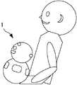
図5Aは、ロボット1の持ち上げられた状態を示す。持ち上げ状態は、ロボット1の姿勢が変化せず、上に持ち上げられた状態であって、加速度が検出される状態である。持ち上げ状態では、所定の対象がコミュニケーションを開始する意思があると想定される。 FIG. 5A shows the lifted state of the
図4のステップS401で、加速度が閾値TA以下であれば(ステップS401;N)、上記の角速度(ロボット1の角速度の絶対値)が閾値TVより大きいか否かを判別する(ステップS402)。加速度が閾値TA以下で、かつ、角速度が閾値TVより大きければ(ステップS402;Y)、状態判定部14は、いずれかの接触センサ5の接触データがオンであるか否かを判別する(ステップS403)。いずれかの接触データがオンであれば(ステップS403;Y)、状態判定部14はロボット1が対象に抱っこされていると判定して、状態に“2”をセットして(ステップS406)、本処理を終了する。 In step S401 of FIG. 4, if the acceleration is equal to or less than the threshold value TA (step S401; N), it is determined whether or not the above angular velocity (absolute value of the angular velocity of the robot 1) is larger than the threshold value TV (step S402). If the acceleration is equal to or less than the threshold value TA and the angular velocity is greater than the threshold value TV (step S402; Y), the state determination unit 14 determines whether or not the contact data of any of the
図5Bは、ロボット1が所定の対象に抱っこされた状態を示す。この抱っこの状態では、ロボット1は、所定の対象の上体に接して、所定の対象の手で保持されている状態にある。このとき、ロボット1の加速度は小さいが、ロボット1の角速度が発生し、ロボット1が所定の対象の手で保持されているので、いずれかの接触センサ5の接触データがオンになる。抱っこの状態では、所定の対象との積極的なコミュニケーションが想定される。 FIG. 5B shows a state in which the
図4のステップS403で、いずれの接触センサ5の接触データもオフであれば(ステップS403;N)、状態判定部14はロボット1が対象の手、膝または体の上に置かれた状態と判定して、状態に“3”をセットして(ステップS407)、本処理を終了する。 If the contact data of any of the
図5Cは、ロボットが手、膝または体の上に置かれた状態を示す。ロボット1が所定の対象の手、膝または体の上に置かれた状態では、抱っこの状態と同じように加速度は小さいが角速度が発生し、所定の対象の手は触れていないので接触センサ5の接触データはいずれもオフである。この状態では、所定の対象はコミュニケーションする意欲が小さいと想定される。 FIG. 5C shows the robot resting on a hand, lap or body. When the
図4のステップS402で角速度が閾値TV以下であれば(ステップS402;N)、状態判定部14は、いずれかの接触センサ5の接触データがオンであるかどうかを判別する(ステップS404)。加速度が閾値TA以下で、角速度が閾値TV以下であり、かつ、いずれかの接触データがオンであれば(ステップS404;Y)、状態判定部14はロボット1が対象に撫でられていると判定して、状態に“4”をセットして(ステップS408)、本処理を終了する。 If the angular velocity is equal to or less than the threshold TV in step S402 of FIG. 4 (step S402; N), the state determination unit 14 determines whether or not the contact data of any of the
図5Dは、ロボットの撫でられ状態を示す。ロボット1が所定の対象に撫でられている状態では、加速度および角速度は発生せず、いずれかの接触センサ5の接触データがオンの状態である。一般に撫でられるとは、手のストロークを伴うことを指すと考えられるが、単に所定の対象の手がロボット1に置かれた場合も撫でられ状態に含めてもよい。撫でられ状態では、所定の対象の積極的なコミュニケーションが想定される。 FIG. 5D shows the stroked state of the robot. In the state where the
図4のステップS404で、加速度が閾値TA以下で、角速度が閾値TV以下であり、かつ、いずれの接触センサ5の接触データもオフであれば(ステップS404;N)、状態判定部14はロボット1が待機状態であると判定して、状態に“0”をセットして(ステップS409)、本処理を終了する。 In step S404 of FIG. 4, if the acceleration is equal to or less than the threshold TA, the angular velocity is equal to or less than the threshold TV, and the contact data of any of the
図5Eは、ロボットが待機状態であることを示す。ロボット1の待機状態は、ロボット1が床または台の上に置かれて静止しており、所定の対象がロボット1に触れていない状態である。このとき、加速度および角速度は発生せず、すべての接触センサ5の接触データはオフである。待機状態では、所定の対象がコミュニケーションを積極的に欲していないと想定される。 FIG. 5E shows that the robot is in a standby state. The standby state of the
図4の状態判定処理を終了したら、図3のフローチャートに戻って、ステップS303からマイク・応答制御処理を再開する。なお、制御装置10の電源オンになった初期には、ロボット1の直前の状態が待機状態に設定される。 When the state determination process of FIG. 4 is completed, the process returns to the flowchart of FIG. 3 and the microphone / response control process is restarted from step S303. At the initial stage when the power of the
図6は、実施の形態に係るマイク制御処理を示すフローチャートである。図6のフローチャートは、図3のフローチャートのステップS304の内容を示す。状態を表す変数は、状態判定部14からマイク制御部13に送られる。マイク制御部13は、状態を表す変数の値に応じて、前面マイクロフォン2および背面マイクロフォン3の検出状態としての感度を制御する。以下、状態を表す変数を「状態」という。 FIG. 6 is a flowchart showing a microphone control process according to the embodiment. The flowchart of FIG. 6 shows the contents of step S304 of the flowchart of FIG. The variable representing the state is sent from the state determination unit 14 to the
まず、状態=1であるか否かを判別する(ステップS601)。状態=1であれば(ステップS601;Y)、ロボット1が持ち上げ状態にあるので、マイク制御部13は前面マイクロフォン2の感度を“中”に設定し(ステップS605)、背面マイクロフォン3の感度を“中”に設定して(ステップS606)、マイク制御を終了する。ロボット1が持ち上げ状態にある場合は、多様な抱き上げ方・多方向からの話かけに対応するため、マイク制御部13は、全てのマイクロフォンの感度レベルを、通常レベルである“中”に設定し、様々な話しかけに対応できるように制御する。 First, it is determined whether or not the state = 1 (step S601). If the state = 1 (step S601; Y), the
一方、状態=1でなければ(ステップS601;N)、状態=2であるか否かを判別する(ステップS602)。状態=2であれば(ステップS602;Y)、ロボット1が抱っこ状態にあるから、前面マイクロフォン2の感度を“高”に設定し(ステップS607)、背面マイクロフォン3をオフにして(ステップS608)、マイク制御を終了する。ロボット1が抱っこ状態にある場合には、所定の対象に話しかけられる機会の増加が想定されるので、小さい声にも敏感に反応し、人に密着している分周囲の音には鈍感に対応するため、マイク制御部13はこのように、指向性の前面マイクロフォン2のみ感度を高い状態に上げ、サブの背面マイクロフォン3をオフにする。これにより、一緒にいる所定の対象の声のみに繊細に反応し、余計な音に反応しないように、前面マイクロフォン2及び背面マイクロフォン3の検出状態を制御する。 On the other hand, if the state is not 1 (step S601; N), it is determined whether or not the state is 2 (step S602). If the state = 2 (step S602; Y), since the
状態=1でも状態=2でもなければ(ステップS601;N、ステップS602;N)、状態=3であるか否かを判別する(ステップS603)。状態=3であれば(ステップS603;Y)、ロボット1は手、膝または体の上に置かれた状態にあるので、前面マイクロフォン2の感度を“中”に設定し(ステップS609)、背面マイクロフォン3の感度を“中”に設定して(ステップS610)、マイク制御を終了する。ロボット1が、所定の対象の手、膝または体の上に置かれた状態にある場合は、所定の対象は一緒にいるが積極的なコミュニケーションは取らないリラックスタイムの対応として、マイク制御部13は、前面マイクロフォン2および背面マイクロフォン3の感度レベルを、通常レベルである“中”に設定し、時折の話しかけにも対応できるよう検出状態を制御する。 If neither state = 1 nor state = 2 (step S601; N, step S602; N), it is determined whether or not the state is 3 (step S603). If state = 3 (step S603; Y), the
ステップS603で状態=3でなければ(ステップS603;N)、状態=4であるか否かを判別する(ステップS604)。状態=4であれば(ステップS604;Y)、ロボット1は所定の対象に撫でられている状態にあるから、前面マイクロフォン2の感度を“高”に設定し(ステップS611)、背面マイクロフォン3の感度を“高”に設定する(ステップS612)。ロボット1が撫でられ状態にある場合は、ロボット1は台または床に置かれている状態で所定の対象に撫でられており、多方向からの話かけに敏感に反応するため、マイク制御部13は、前面マイクロフォン2および背面マイクロフォン3の感度レベルを高い状態に上げ、様々な話しかけに対応できるよう検出状態を制御する。 If the state is not 3 in step S603 (step S603; N), it is determined whether or not the state is 4 (step S604). If the state = 4 (step S604; Y), the
ステップS604で状態=4でなければ(ステップS604;N)、状態=0であって、ロボット1は待機状態にあるから、前面マイクロフォン2の感度を“低”に設定し(ステップS613)、背面マイクロフォン3の感度を“低”に設定する(ステップS614)。ロボット1が待機状態にある場合は、所定の対象がコミュニケーションを積極的に欲していないと想定されるので、全てのマイクロフォンの感度を下げ、周囲の音に敏感に反応しないよう検出状態を制御する。なお、制御装置10の電源オンになった初期には、前面マイクロフォン2および背面マイクロフォン3の感度が、待機状態に対応する“低”に設定される。 If the state is not 4 in step S604 (step S604; N), the state is 0, and the
以上説明したように、実施の形態の制御装置10によれば、制御装置10が前面マイクロフォン2および背面マイクロフォン3を備え、加速度センサ6で検出したロボット1の加速度、ジャイロセンサ7で検出したロボット1の角速度、および接触センサ5で検出した所定の対象の接触の有無で、状態判定部14がロボット1の保持状態を判定し、判定した状態に基づいてマイク制御部13が前面マイクロフォン2および背面マイクロフォン3それぞれの検出状態である感度を制御するので、それぞれの保持状態で適切に所定の対象の発話を音声認識して、対応する応答文を選択して出力することができる。その結果、所定の対象によるロボット1の保持状態によらず、所定の対象に関する情報を適切に取得することができる。 As described above, according to the
実施の形態の制御装置10では、保持または接触の状態によってロボット1の反応が所定の対象に求められているかどうかを判定し、それに応じてマイクロフォンや音検出のレベルを制御することで、所定の対象に関する情報を適切に取得し、それに対応した応答文を音声で出力するので、所定の対象は何も意識せずに自分にとって快適な音声コミュニケーションを行うことができる。ロボット1はまた、所定の対象に対するロボット1の位置および状態によって制御するマイクロフォンを切り替えることで、本当に必要な音声にのみ敏感に応答することができる。 In the
実施の形態によれば、ロボット1に対する所定の対象の自然な動作で制御されるので、ロボット1は、内部処理として、常時、検出されている音声(発話)がコミュニケーションとして、対応を求められているかどうかを解析する必要がない。 According to the embodiment, since the
なお、実施の形態では、ロボット1の保持状態に応じて、マイク制御部13が前面マイクロフォン2および背面マイクロフォン3の感度を設定することで、前面マイクロフォン2および背面マイクロフォン3の検出状態を制御したが、例えば、前面マイクロフォン2および背面マイクロフォン3それぞれの感度およびオン/オフを制御する代わりに、前面マイクロフォン2または背面マイクロフォン3で検出した音声信号を音声データに変換しなかったり、または、前面マイクロフォン2および背面マイクロフォン3の音声信号から取得した音声データを音声認識部12に送らなかったりして、前面マイクロフォン2および背面マイクロフォン3それぞれの音声信号を音声認識に用いないことによって、前面マイクロフォン2および背面マイクロフォン3それぞれの検出結果を制御してもよい。あるいは、前面マイクロフォン2および背面マイクロフォン3の感度を変化させて検出状態を制御する代わりに、前面マイクロフォン2および背面マイクロフォン3それぞれの音声信号を増大させたり、減少させたり(振幅=0を含む)して、前面マイクロフォン2および背面マイクロフォン3それぞれの検出結果を制御してもよい。 In the embodiment, the
実施の形態では、ロボット1の制御装置10が前面マイクロフォン2および背面マイクロフォン3を備え、加速度センサ6で検出した加速度、ジャイロセンサ7で検出した角速度および接触センサで検出した接触の有無で、状態判定部14がロボット1の保持状態を判定し、判定した保持状態に基づいてマイク制御部13が前面マイクロフォン2および背面マイクロフォン3それぞれの感度を制御したが、この構成以外に様々な変形が可能である。例えば、制御装置10が備えるマイクロフォンは2つに限らず、1つまたは3つ以上のマイクロフォンを備えて、それぞれの検出状態または検出結果を制御してもよい。また、制御装置10がステレオマイクロフォンを備え、ロボット1に対する所定の対象の方位を推定してもよい。 In the embodiment, the
制御装置10は、検出状態または検出結果を制御する対象センサとして、マイクロフォン以外に撮像装置(カメラ)を備えてもよい。撮像装置を用いて所定の対象の表情、姿勢または動きを捉え、それに応じたコミュニケーションを生成することができる。撮像装置を備える場合、ロボット1の状態によって、複数の撮像装置の切替、撮像装置それぞれのオン/オフ、画角の広狭、および撮像装置の向きなどを制御することができる。また、撮像装置の画像から、所定の対象の位置を把握し、所定の対象の位置に応じてマイクロフォンの検出状態または検出結果を制御してもよい。 The
ロボット1の保持および接触の状態を検出するのは、加速度センサ6、ジャイロセンサ7および接触センサ5に限らない。前述の撮像装置の他、例えば、赤外線センサを備えて、ロボット1に対する所定の対象の位置を把握し、所定の対象の位置に応じてマイクロフォンの検出状態または検出結果を制御することができる。 It is not limited to the acceleration sensor 6, the
変形例.
ロボット1の状態を判定するのは、図4に示す状態判定処理に限らない。例えば、以下のように保持状態を判定することができる。Modification example.
Determining the state of the
まず、加速度センサ6で検出する値が変化せず、かつ、ジャイロセンサ7で検出する角速度が0である状態が一定時間継続したときに、状態判定部14はロボット1が静止していると判定する。そのときの加速度(ベクトル)を重力加速度(ベクトル)として、加速度センサ6の座標軸に対する重力加速度の方向を設定する。座標軸に対する重力加速度の方向、あるいは逆に、重力加速度に対する座標軸の向きが、ロボット1の姿勢を表している。 First, when the value detected by the acceleration sensor 6 does not change and the state in which the angular velocity detected by the
状態判定部14は、静止状態の時刻T0から現在時刻tまでジャイロセンサ7で検出した角速度を積分して、T0からtまでの方位変化θ(t)を計測する。静止時刻T0から現在時刻tまでの方位変化θ(t)で加速度センサ6の値(ベクトル)を静止状態の座標に変換し、重力加速度を引いて、時刻tにおける移動の加速度(ベクトル)a(t)を算出できる。The state determination unit 14 integrates the angular velocities detected by the
状態判定部14は、静止時刻T0から現在時刻tまで移動の加速度a(t)を積分して、時刻tにおける速度v(t)を得る。T0からtまで速度v(t)を積分して、T0からtまでの変位x(t)を得る。速度vが0になったとき(時刻T1)、静止したと判定できる。時刻T1で静止して、加速度センサ6で検出する値が変化せず、かつ、角速度=0の状態が一定時間継続したときにときに、重力加速度(ベクトル)=姿勢を再設定する(誤差補正)。The state determination unit 14 integrates the acceleration a (t) of the movement from the stationary time T0 to the current time t to obtain the velocity v (t) at the time t. By integrating the velocity v (t) from T0 to t, obtaining the displacement x (t) fromT 0 to t. When the velocity v becomes 0 (time T1 ), it can be determined that the vehicle has stopped. Stationary at time T1, the value detected is not changed by the acceleration sensor 6, and, when when the state of the angular velocity = 0 has continued for a predetermined time, resets the gravitational acceleration (vector) = position (error correction).
静止状態(時刻T0)で、移動の加速度aおよび角速度の少なくとも1つに0でない値が検出されたか、あるいは、接触センサ5に変化が検出されてから、再び静止状態になったとき(時刻T1)に、状態判定部14は、ロボット1の状態を判定する。状態判定部14は、直前の静止(時刻T0)から現在の静止(時刻T1)までの間の変位x(T1)および方位変化θ(T1)、ならびに時刻T1における接触センサ5の接触データのオン/オフ(接触有無)で、ロボット1の状態を判定する。状態の判定条件は、例えば、以下のとおりである。In the stationary state (time T0 ), when a non-zero value is detected in at least one of the movement acceleration a and the angular velocity, or when the
(1)変位あり、方位変化なし、接触あり:状態=移動&撫でられ(保持)
(2)変位あり、方位変化なし、接触なし:状態=移動
(3)変位あり、方位変化あり、接触あり:状態=抱っこ
(4)変位あり、方位変化あり、接触なし:状態=手、膝、体の上
(5)変位なし、方位変化なし、接触あり:状態=撫でられ
(6)変位なし、方位変化なし、接触なし:状態=待機
(6)の状態=待機は、状態=撫でられからの変化と考えられるので、一定時間、所定の対象の発話が検出されなかったときに待機状態に遷移する。(1) Displacement, no orientation change, contact: state = move & stroke (hold)
(2) Displacement, no orientation change, no contact: state = movement (3) displacement, orientation change, contact: state = hug (4) displacement, orientation change, no contact: condition = hand, knee , Above the body (5) No displacement, no orientation change, with contact: state = stroked (6) No displacement, no orientation change, no contact: state = standby (6) state = standby, state = stroked Since it is considered to be a change from, the state transitions to the standby state when the utterance of a predetermined target is not detected for a certain period of time.
変位なし、かつ、方位変化ありの条件は通常考えられないが、その場合を状態=移動に含めてもよい。すなわち、以下のとおりである。
(7)変位なし、方位変化あり、接触あり:状態=移動&撫でられ
(8)変位なし、方位変化あり、接触なし:状態=移動A condition without displacement and with a change in orientation is usually unthinkable, but that case may be included in the state = movement. That is, it is as follows.
(7) No displacement, azimuth change, contact: state = move & stroked (8) No displacement, azimuth change, no contact: state = move
(5)の変位なし、方位変化なしかつ接触なしの判定では、接触センサ5だけがオンになった場合は、直ちに、または検出を確定する時間の後に、状態=撫でられと判定する。なお、(2)状態=移動、および(8)状態=移動ののち、加速度変化、角速度変化および接触変化がなく、所定の対象者の発話がない状態が一定時間継続した場合は、待機状態に遷移する。 In the determination of no displacement, no azimuth change, and no contact in (5), when only the
なお、ロボット1がいずれの状態にあっても、所定の対象者の発話を検出した場合には、マイク制御部13は、前面マイクロフォン2および背面マイクロフォン3のそれぞれを、発話を認識できる適度な感度に設定する。その状態で会話が終了し、所定の対象者の発話が一定時間検出されなかったときに、制御装置10は、元の状態に復帰する。 When the
上述のとおり、状態判定したのち、状態に応じてマイクロフォンを制御するのは、実施の形態と同様である。変形例によれば、動いている間は状態が変化せず、動作が安定する。 As described above, it is the same as the embodiment that the microphone is controlled according to the state after the state is determined. According to the modified example, the state does not change while moving, and the operation is stable.
変形例ではさらに、加速度または角速度に基づく状態判定と組み合わせてもよい。状態判定部14は、例えば、静止状態(T0)から移動の加速度aおよび角速度の少なくとも1つに0でない値が検出されたときに、ロボット1の状態を移動中と判定し、その後、静止状態(速度=0)になるまで、状態=移動中を維持する。状態=移動中では、マイク制御部13は、例えば実施の形態の持ち上げ状態と同様に、前面マイクロフォン2および背面マイクロフォン3の感度を“中”に設定する。状態=移動中から静止状態になったとき(時刻T1)に、状態判定部14は、上述の(1)〜(8)の条件でロボット1の状態を判定する。In the modified example, it may be further combined with the state determination based on the acceleration or the angular velocity. The state determination unit 14 determines that the state of the
このように、加速度または角速度に基づく状態判定と組み合わせることによって、移動中または方位が変化しているときでも、前面マイクロフォン2および背面マイクロフォン3の検出状態または検出結果を適切に制御することができる。 In this way, by combining with the state determination based on the acceleration or the angular velocity, the detection state or the detection result of the
以上の構成の変化および変形例のほか、さまざまな変形と派生が可能である。例えば、ロボット1の形状は、図1Aおよび図1Bに示した形状に限らない。例えば、犬または猫をはじめとして、ペットを模した形状とすることができる。ロボット1は、また、ぬいぐるみやアニメなどのキャラクタの形状であってもよい。 In addition to the above configuration changes and modification examples, various transformations and derivations are possible. For example, the shape of the
あるいはさらに、ロボット1は、スマートフォンまたはタブレットなどの画面に表示されるアバターであってもよい。ロボット1がアバターである場合、状態判定部14は、スマートフォンまたはタブレットの加速度および角速度、ならびに画面上に表示されたアバター部分への接触などで、ロボット1としてのアバターの保持状態を判定できる。その場合、制御装置10は、スマートフォンまたはタブレットにインストールされるアプリケーションプログラムで実現することができる。 Alternatively, the
制御装置10が所定の対象に応答する手段は、応答文を音声で出力することに限らず、ロボット1が備える頭、手または腕などの動作でもよい。応答する手段は、また、眉、目、鼻、口などを動かして、顔の表情を変えたり、ディスプレイ式の目の表示態様を変えるものでもよい。応答文を音声で出力する場合でも、ロボット1の保持状態に応じて、発声する声音、イントネーション、リズムなどを変化させて、音声に表情をつけてもよい。 The means by which the
制御装置10は、CPUの代わりに、例えばASIC(Application Specific Integrated Circuit)、FPGA(Field-Programmable Gate Array)、または、各種制御回路等の専用のハードウェアを備え、専用のハードウェアが、図2に示した各部として機能してもよい。この場合、各部の機能それぞれを個別のハードウェアで実現してもよいし、各部の機能をまとめて単一のハードウェアで実現することもできる。また、各部の機能のうちの、一部を専用のハードウェアによって実現し、他の一部をソフトウェアまたはファームウェアによって実現してもよい。 The
制御装置10の各機能を実現するプログラムは、例えば、フレキシブルディスク、CD(Compact Disc)−ROM、DVD(Digital Versatile Disc)−ROM、メモリカード等のコンピュータ読み取り可能な記憶媒体に格納して適用できる。さらに、プログラムを搬送波に重畳し、インターネットなどの通信媒体を介して適用することもできる。例えば、通信ネットワーク上の掲示板(BBS:Bulletin Board System)にプログラムを掲示して配信してもよい。そして、このプログラムを起動し、OS(Operating System)の制御下で、他のアプリケーションプログラムと同様に実行することにより、上記の処理を実行できるように構成してもよい。 The program that realizes each function of the
以上、本発明の好ましい実施の形態について説明したが、本発明はかかる特定の実施の形態に限定されるものではなく、本発明には、特許請求の範囲に記載された発明とその均等の範囲とが含まれる。以下に、本願出願の当初の特許請求の範囲に記載された発明を付記する。 Although the preferred embodiment of the present invention has been described above, the present invention is not limited to such a specific embodiment, and the present invention includes the invention described in the claims and the equivalent range thereof. And are included. Hereinafter, the inventions described in the claims of the original application of the present application will be added.
(付記1)
ロボットに設けられ、所定の対象に関する情報を検出するための対象センサと、
前記所定の対象による前記ロボットの保持状態を判定する第1判定手段と、
前記第1判定手段により判定された前記ロボットの保持状態に応じて、前記対象センサの検出状態又は検出結果を制御する制御手段と、
を備えることを特徴とする制御装置。(Appendix 1)
A target sensor provided on the robot to detect information about a predetermined target,
A first determination means for determining the holding state of the robot by the predetermined object, and
A control means for controlling the detection state or the detection result of the target sensor according to the holding state of the robot determined by the first determination means.
A control device characterized by comprising.
(付記2)
前記対象センサは、前記ロボットの互いに異なる複数の部位に対応させて設けられた複数の対象センサで構成されており、
前記制御手段は、前記ロボットの保持状態に応じて、前記複数の対象センサの各々の検出状態としてのオン/オフと感度との少なくとも一方を制御する
ことを特徴とする、付記1に記載の制御装置。(Appendix 2)
The target sensor is composed of a plurality of target sensors provided so as to correspond to a plurality of different parts of the robot.
The control according to
(付記3)
前記所定の対象が前記ロボットを保持せずに撫でているか否かを判定する第2判定手段をさらに備え、
前記制御手段は、前記第2判定手段が、前記所定の対象が前記ロボットを保持せずに撫でていると判定している場合に、前記所定の対象が前記ロボットを保持せずに撫でていない場合よりも、前記対象センサの検出状態としての感度を高めるように制御する
ことを特徴とする、付記1又は2に記載の制御装置。(Appendix 3)
Further provided with a second determination means for determining whether or not the predetermined object is stroking without holding the robot.
When the second determination means determines that the predetermined object is stroking without holding the robot, the control means does not stroke the predetermined object without holding the robot. The control device according to
(付記4)
前記第1判定手段は、前記所定の対象により前記ロボットが保持されているか否かを判定し、
前記制御手段は、前記所定の対象により前記ロボットが保持されていると判定されている場合と、前記所定の対象により前記ロボットが保持されていないと判定されている場合とで、前記対象センサの検出状態又は検出結果を互いに異ならせるように制御する
ことを特徴とする、付記1から3の何れか1つに記載の制御装置。(Appendix 4)
The first determination means determines whether or not the robot is held by the predetermined target, and determines whether or not the robot is held.
The control means determines that the robot is held by the predetermined target and that the robot is not held by the predetermined target of the target sensor. The control device according to any one of
(付記5)
前記第1判定手段は、前記所定の対象に保持されている前記ロボットの保持状態の種類を判定し、
前記制御手段は、前記第1判定手段により判定された前記ロボットの保持状態の種類に応じて、前記対象センサの検出状態又は検出結果を制御する
ことを特徴とする、付記1から3の何れか1つに記載の制御装置。(Appendix 5)
The first determination means determines the type of holding state of the robot held by the predetermined object, and determines the type of the holding state.
The control means is any one of
(付記6)
前記対象センサは、前記所定の対象の音声を検出するマイクロフォンを含むことを特徴とする、付記1から5の何れか1つに記載の制御装置。(Appendix 6)
The control device according to any one of
(付記7)
前記対象センサとは異なる、前記ロボットの加速度を検出する加速度センサ、前記ロボットの角速度を検出するジャイロセンサ、及び、前記ロボットへの所定の対象の接触を検出する接触センサのうちの少なくとも1つのセンサをさらに備え、
前記第1判定手段は、前記少なくとも1つのセンサの検出結果に基づいて、前記所定の対象による前記ロボットの保持状態を判定する
ことを特徴とする、付記1から6の何れか1つに記載の制御装置。(Appendix 7)
At least one sensor of an acceleration sensor that detects the acceleration of the robot, a gyro sensor that detects the angular velocity of the robot, and a contact sensor that detects the contact of a predetermined target with the robot, which is different from the target sensor. With more
The first determination means according to any one of
(付記8)
前記ロボットは、所定の動作を実行可能に構成され、
前記制御手段は、前記制御された前記対象センサの検出状態又は検出結果に応じて、前記ロボットによる前記所定の動作を制御する
ことを特徴とする、付記1から7の何れか1つに記載の制御装置。(Appendix 8)
The robot is configured to be capable of performing a predetermined operation.
The control means according to any one of
(付記9)
付記1から8の何れか1つに記載の制御装置を備えるロボット。(Appendix 9)
A robot including the control device according to any one of
(付記10)
所定の対象に関する情報を検出するための対象センサが設けられたロボットの制御方法であって、
前記所定の対象による前記ロボットの保持状態を判定する第1判定ステップと、
前記第1判定ステップにより判定された前記ロボットの保持状態に応じて、前記対象センサの検出状態又は検出結果を制御する制御ステップと、
を備えることを特徴とする制御方法。(Appendix 10)
It is a control method of a robot provided with a target sensor for detecting information about a predetermined target.
The first determination step of determining the holding state of the robot by the predetermined object, and
A control step that controls the detection state or the detection result of the target sensor according to the holding state of the robot determined by the first determination step.
A control method characterized by comprising.
(付記11)
所定の対象に関する情報を検出するための対象センサが設けられたロボットを制御するためのコンピュータを、
前記所定の対象による前記ロボットの保持状態を判定する第1判定手段、および
前記第1判定手段により判定された前記ロボットの保持状態に応じて、前記対象センサの検出状態又は検出結果を制御する制御手段、
として機能させることを特徴とするプログラム。(Appendix 11)
A computer for controlling a robot equipped with a target sensor for detecting information about a predetermined target,
A first determination means for determining the holding state of the robot by the predetermined target, and a control for controlling the detection state or the detection result of the target sensor according to the holding state of the robot determined by the first determination means. means,
A program characterized by functioning as.
1…ロボット、2…前面マイクロフォン、3…背面マイクロフォン、4…スピーカ、5…接触センサ、6…加速度センサ、7…ジャイロセンサ、10…制御装置、11…音声取得部、12…音声認識部、13…マイク制御部、14…状態判定部、15…音声出力部、16…応答制御部1 ... Robot, 2 ... Front microphone, 3 ... Rear microphone, 4 ... Speaker, 5 ... Contact sensor, 6 ... Accelerometer, 7 ... Gyro sensor, 10 ... Control device, 11 ... Voice acquisition unit, 12 ... Voice recognition unit, 13 ... Microphone control unit, 14 ... Status determination unit, 15 ... Audio output unit, 16 ... Response control unit
Claims (11)
Translated fromJapanese前記所定の対象による前記ロボットの保持状態を判定する第1判定手段と、
前記第1判定手段により判定された前記ロボットの保持状態に応じて、前記対象センサの検出状態又は検出結果を制御する制御手段と、
を備えることを特徴とする制御装置。A target sensor provided on the robot to detect information about a predetermined target,
A first determination means for determining the holding state of the robot by the predetermined object, and
A control means for controlling the detection state or the detection result of the target sensor according to the holding state of the robot determined by the first determination means.
A control device characterized by comprising.
前記制御手段は、前記ロボットの保持状態に応じて、前記複数の対象センサの各々の検出状態としてのオン/オフと感度との少なくとも一方を制御する
ことを特徴とする、請求項1に記載の制御装置。The target sensor is composed of a plurality of target sensors provided so as to correspond to a plurality of different parts of the robot.
The control means according to claim 1, wherein the control means controls at least one of the on / off and the sensitivity of each of the plurality of target sensors as a detection state according to the holding state of the robot. Control device.
前記制御手段は、前記第2判定手段が、前記所定の対象が前記ロボットを保持せずに撫でていると判定している場合に、前記所定の対象が前記ロボットを保持せずに撫でていない場合よりも、前記対象センサの検出状態としての感度を高めるように制御する
ことを特徴とする、請求項1又は2に記載の制御装置。Further provided with a second determination means for determining whether or not the predetermined object is stroking without holding the robot.
When the second determination means determines that the predetermined target is stroking without holding the robot, the control means does not stroke the predetermined target without holding the robot. The control device according to claim 1 or 2, wherein the control device is controlled so as to increase the sensitivity of the target sensor as a detection state.
前記制御手段は、前記所定の対象により前記ロボットが保持されていると判定されている場合と、前記所定の対象により前記ロボットが保持されていないと判定されている場合とで、前記対象センサの検出状態又は検出結果を互いに異ならせるように制御する
ことを特徴とする、請求項1から3の何れか1項に記載の制御装置。The first determination means determines whether or not the robot is held by the predetermined target, and determines whether or not the robot is held.
The control means has a case where it is determined that the robot is held by the predetermined target and a case where it is determined that the robot is not held by the predetermined target. The control device according to any one of claims 1 to 3, wherein the detection state or the detection result is controlled so as to be different from each other.
前記制御手段は、前記第1判定手段により判定された前記ロボットの保持状態の種類に応じて、前記対象センサの検出状態又は検出結果を制御する
ことを特徴とする、請求項1から3の何れか1項に記載の制御装置。The first determination means determines the type of holding state of the robot held by the predetermined object, and determines the type of the holding state.
Any of claims 1 to 3, wherein the control means controls the detection state or the detection result of the target sensor according to the type of the holding state of the robot determined by the first determination means. The control device according to item 1.
前記第1判定手段は、前記少なくとも1つのセンサの検出結果に基づいて、前記所定の対象による前記ロボットの保持状態を判定する
ことを特徴とする、請求項1から6の何れか1項に記載の制御装置。At least one sensor of an acceleration sensor that detects the acceleration of the robot, a gyro sensor that detects the angular velocity of the robot, and a contact sensor that detects the contact of a predetermined target with the robot, which is different from the target sensor. With more
The first determination means according to any one of claims 1 to 6, wherein the first determination means determines the holding state of the robot by the predetermined object based on the detection result of the at least one sensor. Control device.
前記制御手段は、前記制御された前記対象センサの検出状態又は検出結果に応じて、前記ロボットによる前記所定の動作を制御する
ことを特徴とする、請求項1から7の何れか1項に記載の制御装置。The robot is configured to be capable of performing a predetermined operation.
The control means according to any one of claims 1 to 7, wherein the control means controls the predetermined operation by the robot according to the detected detection state or the detection result of the controlled target sensor. Control device.
前記所定の対象による前記ロボットの保持状態を判定する第1判定ステップと、
前記第1判定ステップにより判定された前記ロボットの保持状態に応じて、前記対象センサの検出状態又は検出結果を制御する制御ステップと、
を備えることを特徴とする制御方法。It is a control method of a robot provided with a target sensor for detecting information about a predetermined target.
The first determination step of determining the holding state of the robot by the predetermined object, and
A control step that controls the detection state or the detection result of the target sensor according to the holding state of the robot determined by the first determination step.
A control method characterized by comprising.
前記所定の対象による前記ロボットの保持状態を判定する第1判定手段、および
前記第1判定手段により判定された前記ロボットの保持状態に応じて、前記対象センサの検出状態又は検出結果を制御する制御手段、
として機能させることを特徴とするプログラム。A computer for controlling a robot equipped with a target sensor for detecting information about a predetermined target,
A first determination means for determining the holding state of the robot by the predetermined target, and a control for controlling the detection state or the detection result of the target sensor according to the holding state of the robot determined by the first determination means. means,
A program characterized by functioning as.
Priority Applications (4)
| Application Number | Priority Date | Filing Date | Title |
|---|---|---|---|
| JP2019056936AJP7024754B2 (en) | 2019-03-25 | 2019-03-25 | Controls, robots, control methods and programs |
| CN202010083634.3ACN111730608B (en) | 2019-03-25 | 2020-02-07 | Control device, robot, control method and storage medium |
| CN202310619608.1ACN116442242A (en) | 2019-03-25 | 2020-02-07 | Control device, robot, control method for robot, and recording medium |
| JP2022017099AJP7435641B2 (en) | 2019-03-25 | 2022-02-07 | Control device, robot, control method and program |
Applications Claiming Priority (1)
| Application Number | Priority Date | Filing Date | Title |
|---|---|---|---|
| JP2019056936AJP7024754B2 (en) | 2019-03-25 | 2019-03-25 | Controls, robots, control methods and programs |
Related Child Applications (1)
| Application Number | Title | Priority Date | Filing Date |
|---|---|---|---|
| JP2022017099ADivisionJP7435641B2 (en) | 2019-03-25 | 2022-02-07 | Control device, robot, control method and program |
Publications (2)
| Publication Number | Publication Date |
|---|---|
| JP2020156607Atrue JP2020156607A (en) | 2020-10-01 |
| JP7024754B2 JP7024754B2 (en) | 2022-02-24 |
Family
ID=72640379
Family Applications (2)
| Application Number | Title | Priority Date | Filing Date |
|---|---|---|---|
| JP2019056936AActiveJP7024754B2 (en) | 2019-03-25 | 2019-03-25 | Controls, robots, control methods and programs |
| JP2022017099AActiveJP7435641B2 (en) | 2019-03-25 | 2022-02-07 | Control device, robot, control method and program |
Family Applications After (1)
| Application Number | Title | Priority Date | Filing Date |
|---|---|---|---|
| JP2022017099AActiveJP7435641B2 (en) | 2019-03-25 | 2022-02-07 | Control device, robot, control method and program |
Country Status (2)
| Country | Link |
|---|---|
| JP (2) | JP7024754B2 (en) |
| CN (2) | CN116442242A (en) |
Cited By (1)
| Publication number | Priority date | Publication date | Assignee | Title |
|---|---|---|---|---|
| JP2022149407A (en)* | 2021-03-25 | 2022-10-06 | カシオ計算機株式会社 | Electronic device |
Families Citing this family (1)
| Publication number | Priority date | Publication date | Assignee | Title |
|---|---|---|---|---|
| JP7585946B2 (en)* | 2021-04-14 | 2024-11-19 | トヨタ自動車株式会社 | Remote robot system and method for controlling the remote robot system |
Citations (5)
| Publication number | Priority date | Publication date | Assignee | Title |
|---|---|---|---|---|
| JP2002140070A (en)* | 2000-10-31 | 2002-05-17 | Atr Media Integration & Communications Res Lab | Music communication device |
| JP2002224983A (en)* | 2001-01-30 | 2002-08-13 | Nec Corp | Robot and control method |
| JP2003311028A (en)* | 2002-04-26 | 2003-11-05 | Matsushita Electric Ind Co Ltd | Pet robot device |
| JP2005161450A (en)* | 2003-12-02 | 2005-06-23 | Advanced Telecommunication Research Institute International | Communication robot |
| WO2018016461A1 (en)* | 2016-07-20 | 2018-01-25 | Groove X株式会社 | Autonomous-behavior-type robot that understands emotional communication through physical contact |
Family Cites Families (9)
| Publication number | Priority date | Publication date | Assignee | Title |
|---|---|---|---|---|
| JP3885019B2 (en)* | 2002-11-29 | 2007-02-21 | 株式会社東芝 | Security system and mobile robot |
| WO2013168364A1 (en)* | 2012-05-09 | 2013-11-14 | テルモ株式会社 | Speech therapy robot |
| KR101458312B1 (en)* | 2013-06-20 | 2014-11-04 | 한국과학기술원 | Method for detecting touch strength using sound, and user terminal and touch strength sensing system using the same |
| CN109153127B (en)* | 2016-03-28 | 2022-05-31 | Groove X 株式会社 | Behavior autonomous robot for executing head-on behavior |
| JP6671577B2 (en)* | 2016-11-07 | 2020-03-25 | Groove X株式会社 | An autonomous robot that identifies people |
| CN106799736A (en)* | 2017-01-19 | 2017-06-06 | 深圳市鑫益嘉科技股份有限公司 | The interactive triggering method and robot of a kind of robot |
| JP6572943B2 (en)* | 2017-06-23 | 2019-09-11 | カシオ計算機株式会社 | Robot, robot control method and program |
| CN107765891B (en)* | 2017-10-19 | 2021-12-21 | 广东小天才科技有限公司 | Microphone control method and microphone |
| JP6575637B2 (en)* | 2018-05-25 | 2019-09-18 | カシオ計算機株式会社 | Robot, robot control method and program |
- 2019
- 2019-03-25JPJP2019056936Apatent/JP7024754B2/enactiveActive
- 2020
- 2020-02-07CNCN202310619608.1Apatent/CN116442242A/enactivePending
- 2020-02-07CNCN202010083634.3Apatent/CN111730608B/enactiveActive
- 2022
- 2022-02-07JPJP2022017099Apatent/JP7435641B2/enactiveActive
Patent Citations (5)
| Publication number | Priority date | Publication date | Assignee | Title |
|---|---|---|---|---|
| JP2002140070A (en)* | 2000-10-31 | 2002-05-17 | Atr Media Integration & Communications Res Lab | Music communication device |
| JP2002224983A (en)* | 2001-01-30 | 2002-08-13 | Nec Corp | Robot and control method |
| JP2003311028A (en)* | 2002-04-26 | 2003-11-05 | Matsushita Electric Ind Co Ltd | Pet robot device |
| JP2005161450A (en)* | 2003-12-02 | 2005-06-23 | Advanced Telecommunication Research Institute International | Communication robot |
| WO2018016461A1 (en)* | 2016-07-20 | 2018-01-25 | Groove X株式会社 | Autonomous-behavior-type robot that understands emotional communication through physical contact |
Cited By (2)
| Publication number | Priority date | Publication date | Assignee | Title |
|---|---|---|---|---|
| JP2022149407A (en)* | 2021-03-25 | 2022-10-06 | カシオ計算機株式会社 | Electronic device |
| JP7188485B2 (en) | 2021-03-25 | 2022-12-13 | カシオ計算機株式会社 | Electronics |
Also Published As
| Publication number | Publication date |
|---|---|
| CN111730608A (en) | 2020-10-02 |
| CN111730608B (en) | 2023-06-20 |
| CN116442242A (en) | 2023-07-18 |
| JP7435641B2 (en) | 2024-02-21 |
| JP7024754B2 (en) | 2022-02-24 |
| JP2022060288A (en) | 2022-04-14 |
Similar Documents
| Publication | Publication Date | Title |
|---|---|---|
| KR102115222B1 (en) | Electronic device for controlling sound and method for operating thereof | |
| CN114127665B (en) | Multimodal User Interface | |
| KR102463806B1 (en) | Electronic device capable of moving and method for operating thereof | |
| US11338429B2 (en) | Robot | |
| JP5982840B2 (en) | Dialogue device, dialogue program, and dialogue method | |
| KR102740847B1 (en) | Method for processing user input and electronic device supporting the same | |
| JP7476941B2 (en) | ROBOT, ROBOT CONTROL METHOD AND PROGRAM | |
| JP2012040655A (en) | Method for controlling robot, program, and robot | |
| US20250123622A1 (en) | Information processing apparatus, information processing method, and program | |
| JP6565853B2 (en) | Communication device | |
| JP7435641B2 (en) | Control device, robot, control method and program | |
| CN109249386B (en) | Voice conversation robot and voice conversation system | |
| JPWO2008001492A1 (en) | Robot, robot control method, and robot control program | |
| JP2019175432A (en) | Dialogue control device, dialogue system, dialogue control method, and program | |
| US20220371178A1 (en) | Information processing apparatus, information processing method, and program | |
| JP6798258B2 (en) | Generation program, generation device, control program, control method, robot device and call system | |
| WO2016206646A1 (en) | Method and system for urging machine device to generate action | |
| JP2017204231A (en) | Information processing apparatus, information processing method, and information processing program | |
| JP3891020B2 (en) | Robot equipment | |
| JP2001188551A (en) | Device and method for information processing and recording medium | |
| CN111708428A (en) | Communication system and method for controlling communication system | |
| KR102168812B1 (en) | Electronic device for controlling sound and method for operating thereof | |
| JP7605034B2 (en) | Control device, control method, and control program | |
| WO2023006033A1 (en) | Speech interaction method, electronic device, and medium | |
| JP4735965B2 (en) | Remote communication system |
Legal Events
| Date | Code | Title | Description |
|---|---|---|---|
| A621 | Written request for application examination | Free format text:JAPANESE INTERMEDIATE CODE: A621 Effective date:20200701 | |
| A977 | Report on retrieval | Free format text:JAPANESE INTERMEDIATE CODE: A971007 Effective date:20210531 | |
| A131 | Notification of reasons for refusal | Free format text:JAPANESE INTERMEDIATE CODE: A131 Effective date:20210608 | |
| A521 | Request for written amendment filed | Free format text:JAPANESE INTERMEDIATE CODE: A523 Effective date:20210810 | |
| TRDD | Decision of grant or rejection written | ||
| A01 | Written decision to grant a patent or to grant a registration (utility model) | Free format text:JAPANESE INTERMEDIATE CODE: A01 Effective date:20220111 | |
| A61 | First payment of annual fees (during grant procedure) | Free format text:JAPANESE INTERMEDIATE CODE: A61 Effective date:20220124 | |
| R150 | Certificate of patent or registration of utility model | Ref document number:7024754 Country of ref document:JP Free format text:JAPANESE INTERMEDIATE CODE: R150 |