JP2020146487A - Mechanical thrombectomy apparatuses and methods - Google Patents
Mechanical thrombectomy apparatuses and methodsDownload PDFInfo
- Publication number
- JP2020146487A JP2020146487AJP2020093260AJP2020093260AJP2020146487AJP 2020146487 AJP2020146487 AJP 2020146487AJP 2020093260 AJP2020093260 AJP 2020093260AJP 2020093260 AJP2020093260 AJP 2020093260AJP 2020146487 AJP2020146487 AJP 2020146487A
- Authority
- JP
- Japan
- Prior art keywords
- catheter
- region
- distal
- distal end
- tractor
- Prior art date
- Legal status (The legal status is an assumption and is not a legal conclusion. Google has not performed a legal analysis and makes no representation as to the accuracy of the status listed.)
- Granted
Links
Images


Classifications
- A—HUMAN NECESSITIES
- A61—MEDICAL OR VETERINARY SCIENCE; HYGIENE
- A61B—DIAGNOSIS; SURGERY; IDENTIFICATION
- A61B17/00—Surgical instruments, devices or methods
- A61B17/22—Implements for squeezing-off ulcers or the like on inner organs of the body; Implements for scraping-out cavities of body organs, e.g. bones; for invasive removal or destruction of calculus using mechanical vibrations; for removing obstructions in blood vessels, not otherwise provided for
- A61B17/221—Gripping devices in the form of loops or baskets for gripping calculi or similar types of obstructions
- A—HUMAN NECESSITIES
- A61—MEDICAL OR VETERINARY SCIENCE; HYGIENE
- A61B—DIAGNOSIS; SURGERY; IDENTIFICATION
- A61B10/00—Instruments for taking body samples for diagnostic purposes; Other methods or instruments for diagnosis, e.g. for vaccination diagnosis, sex determination or ovulation-period determination; Throat striking implements
- A61B10/02—Instruments for taking cell samples or for biopsy
- A61B10/04—Endoscopic instruments, e.g. catheter-type instruments
- A—HUMAN NECESSITIES
- A61—MEDICAL OR VETERINARY SCIENCE; HYGIENE
- A61B—DIAGNOSIS; SURGERY; IDENTIFICATION
- A61B17/00—Surgical instruments, devices or methods
- A61B17/00234—Surgical instruments, devices or methods for minimally invasive surgery
- A—HUMAN NECESSITIES
- A61—MEDICAL OR VETERINARY SCIENCE; HYGIENE
- A61B—DIAGNOSIS; SURGERY; IDENTIFICATION
- A61B17/00—Surgical instruments, devices or methods
- A61B17/22—Implements for squeezing-off ulcers or the like on inner organs of the body; Implements for scraping-out cavities of body organs, e.g. bones; for invasive removal or destruction of calculus using mechanical vibrations; for removing obstructions in blood vessels, not otherwise provided for
- A61B17/22031—Gripping instruments, e.g. forceps, for removing or smashing calculi
- A—HUMAN NECESSITIES
- A61—MEDICAL OR VETERINARY SCIENCE; HYGIENE
- A61B—DIAGNOSIS; SURGERY; IDENTIFICATION
- A61B17/00—Surgical instruments, devices or methods
- A61B17/00234—Surgical instruments, devices or methods for minimally invasive surgery
- A61B2017/00292—Surgical instruments, devices or methods for minimally invasive surgery mounted on or guided by flexible, e.g. catheter-like, means
- A—HUMAN NECESSITIES
- A61—MEDICAL OR VETERINARY SCIENCE; HYGIENE
- A61B—DIAGNOSIS; SURGERY; IDENTIFICATION
- A61B17/00—Surgical instruments, devices or methods
- A61B17/00234—Surgical instruments, devices or methods for minimally invasive surgery
- A61B2017/00358—Snares for grasping
- A—HUMAN NECESSITIES
- A61—MEDICAL OR VETERINARY SCIENCE; HYGIENE
- A61B—DIAGNOSIS; SURGERY; IDENTIFICATION
- A61B17/00—Surgical instruments, devices or methods
- A61B2017/00743—Type of operation; Specification of treatment sites
- A61B2017/00778—Operations on blood vessels
- A—HUMAN NECESSITIES
- A61—MEDICAL OR VETERINARY SCIENCE; HYGIENE
- A61B—DIAGNOSIS; SURGERY; IDENTIFICATION
- A61B17/00—Surgical instruments, devices or methods
- A61B2017/00831—Material properties
- A61B2017/00862—Material properties elastic or resilient
- A—HUMAN NECESSITIES
- A61—MEDICAL OR VETERINARY SCIENCE; HYGIENE
- A61B—DIAGNOSIS; SURGERY; IDENTIFICATION
- A61B17/00—Surgical instruments, devices or methods
- A61B2017/00831—Material properties
- A61B2017/00867—Material properties shape memory effect
- A—HUMAN NECESSITIES
- A61—MEDICAL OR VETERINARY SCIENCE; HYGIENE
- A61B—DIAGNOSIS; SURGERY; IDENTIFICATION
- A61B17/00—Surgical instruments, devices or methods
- A61B17/22—Implements for squeezing-off ulcers or the like on inner organs of the body; Implements for scraping-out cavities of body organs, e.g. bones; for invasive removal or destruction of calculus using mechanical vibrations; for removing obstructions in blood vessels, not otherwise provided for
- A61B2017/22038—Implements for squeezing-off ulcers or the like on inner organs of the body; Implements for scraping-out cavities of body organs, e.g. bones; for invasive removal or destruction of calculus using mechanical vibrations; for removing obstructions in blood vessels, not otherwise provided for with a guide wire
- A61B2017/22042—Details of the tip of the guide wire
- A61B2017/22044—Details of the tip of the guide wire with a pointed tip
- A—HUMAN NECESSITIES
- A61—MEDICAL OR VETERINARY SCIENCE; HYGIENE
- A61B—DIAGNOSIS; SURGERY; IDENTIFICATION
- A61B17/00—Surgical instruments, devices or methods
- A61B17/22—Implements for squeezing-off ulcers or the like on inner organs of the body; Implements for scraping-out cavities of body organs, e.g. bones; for invasive removal or destruction of calculus using mechanical vibrations; for removing obstructions in blood vessels, not otherwise provided for
- A61B2017/22079—Implements for squeezing-off ulcers or the like on inner organs of the body; Implements for scraping-out cavities of body organs, e.g. bones; for invasive removal or destruction of calculus using mechanical vibrations; for removing obstructions in blood vessels, not otherwise provided for with suction of debris
- A—HUMAN NECESSITIES
- A61—MEDICAL OR VETERINARY SCIENCE; HYGIENE
- A61B—DIAGNOSIS; SURGERY; IDENTIFICATION
- A61B17/00—Surgical instruments, devices or methods
- A61B17/22—Implements for squeezing-off ulcers or the like on inner organs of the body; Implements for scraping-out cavities of body organs, e.g. bones; for invasive removal or destruction of calculus using mechanical vibrations; for removing obstructions in blood vessels, not otherwise provided for
- A61B17/221—Gripping devices in the form of loops or baskets for gripping calculi or similar types of obstructions
- A61B2017/2215—Gripping devices in the form of loops or baskets for gripping calculi or similar types of obstructions having an open distal end
- A—HUMAN NECESSITIES
- A61—MEDICAL OR VETERINARY SCIENCE; HYGIENE
- A61B—DIAGNOSIS; SURGERY; IDENTIFICATION
- A61B17/00—Surgical instruments, devices or methods
- A61B17/30—Surgical pincettes, i.e. surgical tweezers without pivotal connections
- A61B2017/306—Surgical pincettes, i.e. surgical tweezers without pivotal connections holding by means of suction
- A—HUMAN NECESSITIES
- A61—MEDICAL OR VETERINARY SCIENCE; HYGIENE
- A61B—DIAGNOSIS; SURGERY; IDENTIFICATION
- A61B17/00—Surgical instruments, devices or methods
- A61B17/34—Trocars; Puncturing needles
- A61B17/3417—Details of tips or shafts, e.g. grooves, expandable, bendable; Multiple coaxial sliding cannulas, e.g. for dilating
- A61B17/3421—Cannulas
- A61B2017/3435—Cannulas using everted sleeves
- A—HUMAN NECESSITIES
- A61—MEDICAL OR VETERINARY SCIENCE; HYGIENE
- A61B—DIAGNOSIS; SURGERY; IDENTIFICATION
- A61B2217/00—General characteristics of surgical instruments
- A61B2217/002—Auxiliary appliance
- A61B2217/005—Auxiliary appliance with suction drainage system
Landscapes
- Health & Medical Sciences (AREA)
- Life Sciences & Earth Sciences (AREA)
- Surgery (AREA)
- Molecular Biology (AREA)
- General Health & Medical Sciences (AREA)
- Biomedical Technology (AREA)
- Heart & Thoracic Surgery (AREA)
- Medical Informatics (AREA)
- Nuclear Medicine, Radiotherapy & Molecular Imaging (AREA)
- Animal Behavior & Ethology (AREA)
- Engineering & Computer Science (AREA)
- Public Health (AREA)
- Veterinary Medicine (AREA)
- Orthopedic Medicine & Surgery (AREA)
- Vascular Medicine (AREA)
- Radiology & Medical Imaging (AREA)
- Pathology (AREA)
- Surgical Instruments (AREA)
- Media Introduction/Drainage Providing Device (AREA)
Abstract
Translated fromJapaneseDescription
Translated fromJapanese[関連出願の相互参照]
本特許出願は、以下の仮特許出願のそれぞれに優先権を主張するものであり、その各々は参照によりその全体が本明細書に組み込まれる:2015年9月28日に出願された米国仮特許出願第62/284,300号、2015年10月8日に出願された米国仮特許出願第62/284,752号、および2015年10月23日に出願された米国仮特許出願第62/245,560号。[Cross-reference of related applications]
This patent application claims priority to each of the following provisional patent applications, each of which is incorporated herein by reference in its entirety: a US provisional patent filed on September 28, 2015. Application No. 62 / 284,300, US Provisional Patent Application No. 62 / 284,752 filed on October 8, 2015, and US Provisional Patent Application No. 62/245 filed on October 23, 2015. , 560.
[参照による組み込み]
本明細書で言及されるすべての刊行物および特許出願は、個々の刊行物または特許出願が具体的にかつ個別に参照により組み入れられることが示されているかのように、全体が参照により本書に組み込まれる。[Built-in by reference]
All publications and patent applications referred to herein are hereby by reference in their entirety, as if the individual publications or patent applications were specifically and individually indicated to be incorporated by reference. Be incorporated.
本書記載の装置および方法は、体内からの物体の機械的除去に関する。より具体的には、機械的な血栓摘出装置および方法が本書に記載されている。 The devices and methods described herein relate to the mechanical removal of objects from the body. More specifically, mechanical thrombectomy devices and methods are described herein.
往々にして、他の組織に損傷を与えないように、できるだけ低侵襲的な方法で身体から組織を除去することが望ましい。例えば、血管系からの組織(例えば、凝血塊)の除去は、患者の状態および生活の質を改善し得る。 Often, it is desirable to remove tissue from the body in the least invasive way possible so as not to damage other tissues. For example, removal of tissue (eg, clots) from the vascular system can improve a patient's condition and quality of life.
多くの血管系の問題は、血管を通る不十分な血流に起因する。不十分または不規則な血流の原因の1つは、凝血塊または血栓と呼ばれる血管内の閉塞である。血栓は多くの理由により生じ、それには外科手術のような外傷の後や他の原因によるものが含まれる。例えば、米国における120万を超える心臓発作の大部分は、冠状動脈内に形成される凝血塊(血栓)によって引き起こされる。 Many vascular problems result from inadequate blood flow through the blood vessels. One of the causes of inadequate or irregular blood flow is an obstruction in a blood vessel called a clot or blood clot. Blood clots occur for many reasons, including after trauma such as surgery and due to other causes. For example, the majority of over 1.2 million heart attacks in the United States are caused by blood clots (thrombus) that form in the coronary arteries.
血栓が形成されると、形成領域を通る血液の流れが事実上止まりうる。血栓が動脈の内径を横切って延在する場合、動脈を通る血流を遮断してしまう。1つの冠状動脈が100%の血栓症となった場合、その動脈内での血流は止まり、例えば心臓壁の筋肉(心筋)へ酸素を運ぶ赤血球の供給が足りなくなる。このような血栓症は、血液の損失を防止するためには不要であるが、アテローム性動脈硬化症による動脈壁の損傷によって動脈内で望ましくなく引き起こされる可能性がある。したがって、アテローム性動脈硬化症の根底にある疾患は、急性酸素欠乏(虚血)を引き起こさないが、誘発された血栓症を介して急性虚血を誘発し得る。同様に、頸動脈の1つの血栓症は、頭蓋内の重要な神経中枢への酸素供給が不十分となるために脳卒中を引き起こすことがある。酸素欠乏は筋肉活動を減少させるか妨げ、胸痛(狭心症)を引き起こし、ひいては心筋が壊死し、恒久的な心臓麻痺となる可能性がある。心筋細胞の壊死が広範囲に及ぶ場合、心臓は、身体の生命維持に必要な血液を十分に送ることができなくなる。虚血の程度は、必要な酸素を提供できる側副血管および側副血行の存在を含む多くの要因によって影響される。 When a thrombus is formed, the flow of blood through the formation area can be effectively stopped. If the thrombus extends across the inner diameter of the artery, it blocks blood flow through the artery. When one coronary artery becomes 100% thrombotic, blood flow in that artery ceases, for example, the supply of red blood cells that carry oxygen to the muscles (myocardium) of the heart wall becomes insufficient. Although such thrombosis is not necessary to prevent blood loss, it can be undesirably caused within the artery by damage to the arterial wall due to atherosclerosis. Thus, the underlying disease of atherosclerosis does not cause acute oxygen deficiency (ischemia), but can induce acute ischemia through induced thrombosis. Similarly, one thrombosis of the carotid artery can cause a stroke due to an inadequate supply of oxygen to important intracranial nerve centers. Oxygen deficiency reduces or impedes muscle activity, causing chest pain (angina) and thus necrosis of the heart muscle, which can lead to permanent heart attack. When cardiomyocyte necrosis is widespread, the heart is unable to deliver enough blood to sustain the body's life. The degree of ischemia is influenced by a number of factors, including the presence of collateral vessels and collateral circulation that can provide the required oxygen.
臨床データは、凝血塊の除去は有益であり、結果の改善のために必要でさえあることを示す。例えば、末梢血管系において、発見と処置により、切断の必要性を80%低減することができる。動脈または静脈系のこれらの状態を治療する物理療法の最終的な目標は、迅速、安全かつ費用対効果よく、閉塞を除去するか開通性を回復させることである。これは、血栓の溶解、細片化、血栓吸引またはこれらの方法の組み合わせによって達成され得る。 Clinical data show that removal of clots is beneficial and even necessary to improve results. For example, in the peripheral vascular system, discovery and treatment can reduce the need for amputation by 80%. The ultimate goal of physical therapy to treat these conditions of the arterial or venous system is to eliminate the obstruction or restore patency quickly, safely and cost-effectively. This can be achieved by thrombus lysis, fragmentation, thrombus aspiration or a combination of these methods.
カテーテルを導入する血栓摘出および血栓溶解は、一般的に、外傷性がより少ないが、従来の外科技術において罹患率および死亡率が下がりにくいと認識されている。近年、冠状動脈への化学溶解剤の直接投与が、冠状動脈を血栓化させた患者に利益をもたらすことが示されている。この処置では、カテーテルを閉塞の直前に置き、ストレプトキナーゼの点滴を血栓の上流側に向けて配置する。ストレプトキナーゼは、時間の経過とともにフィブリン分子を溶解できる酵素である。この処置には数時間かかることがあり、必ずしも血栓破砕に成功するとは限らない。さらに、血栓細片(塞栓)が下流に流れ、小径の支流の閉塞を招く可能性がある。米国特許第4,646,736号は、閉塞性血栓を迅速に除去できる血栓摘出装置を開示している。しかしながら、この装置はカテーテル先端のサイズが小さいことが特徴であり、したがって凝血塊に強い力を加えることができない。また、回転するワイヤの「火線(line of fire)」内の血管壁上の取りやすい位置にない凝血塊は、線維素摘出(fibrinectomize)されない。これは特に、指などの拘束がない場合にこれらの凝血塊内で回転することは事実上不可能であるため、血流中に浮遊している凝血塊の場合に当てはまる。 Catheter-introduced thrombectomy and thrombolysis are generally recognized to be less traumatic, but less likely to reduce morbidity and mortality with conventional surgical techniques. In recent years, direct administration of chemical solubilizers to the coronary arteries has been shown to benefit patients who have thromboized the coronary arteries. In this procedure, the catheter is placed just prior to the occlusion and the streptokinase infusion is placed upstream of the thrombus. Streptokinase is an enzyme that can lyse fibrin molecules over time. This procedure can take several hours and does not always result in successful thrombus crushing. In addition, thrombus debris (embolus) can flow downstream, leading to obstruction of small diameter tributaries. U.S. Pat. No. 4,646,736 discloses a thrombectomy device capable of rapidly removing an obstructive thrombus. However, this device is characterized by a small size of the catheter tip and therefore cannot exert a strong force on the clot. Also, blood clots that are not easily accessible on the vessel wall within the "line of fire" of the rotating wire are not fibrinectomized. This is especially true for clots floating in the bloodstream, as it is virtually impossible to rotate within these clots without restraints such as fingers.
この血栓摘出装置のさらなる別の欠点は、動脈管腔を掃引するのに時には必要である、回転中にワイヤが横に動かされるときに、すべての度合いの回転中に凝血塊をワイヤ上の空間に保持することが困難であることである。事実、動脈管腔全体を回転ワイヤで掃引することは、最小の、すなわち直径1.5mm未満の動脈では事実上不可能である。さらなる重大な不都合は、凝血塊の断片が下流で塞栓する可能性があることである。 Yet another drawback of this thrombectomy device is the space on the wire during all degrees of rotation, when the wire is moved laterally during rotation, which is sometimes necessary to sweep the ductus arteriosus. It is difficult to hold on. In fact, sweeping the entire ductus arteriosus with a rotating wire is virtually impossible with the smallest arteries, i.e. less than 1.5 mm in diameter. A further serious inconvenience is that fragments of the clot can embolize downstream.
塞栓を捕捉するための別のアプローチが、米国特許出願第2015/0005781号に記載されている。この出願には、遠位端から延びるバスケットを有するカテーテルが記載されている。ロッドまたはケーブルといったアクチュエータを近位に引っ張って、バスケットをカテーテル内に引っ込めることができる。残念なことに、バスケットは管腔内部を閉塞し、位置決めおよび/または支持用のガイドワイヤとの同時使用ができず、バスケットはカテーテルの遠位端またはその近傍に保持されなければならない。除去する材料(すなわち凝血塊)の硬さによって、しばしばバスケットを引き戻すとカテーテルの遠位端部が壊れてしまい、使用できなくなり、特に凝血塊を保持しているとバスケットをカテーテル内に引き込むのが困難となる。これによって凝血塊が剪断されることになる。最後に、バスケットは、血管挿入前に予めカテーテルの遠位端に装填する必要があるが、事前の装填は困難で時間がかかり、配備前に装置を破壊する危険がある。 Another approach for capturing embolisms is described in US Patent Application No. 2015/0005781. The application describes a catheter with a basket extending from the distal end. Actuators such as rods or cables can be pulled proximally to retract the basket into the catheter. Unfortunately, the basket occludes the lumen, cannot be used concurrently with positioning and / or supporting guide wires, and the basket must be held at or near the distal end of the catheter. Due to the hardness of the material to be removed (ie, the clot), pulling the basket back often breaks the distal end of the catheter, making it unusable, especially when holding the clot, pulling the basket into the catheter. It will be difficult. This causes the blood clot to be sheared. Finally, the basket must be preloaded into the distal end of the catheter prior to vessel insertion, which is difficult, time consuming and risky to destroy the device prior to deployment.
したがって、血栓摘出装置、特に体内から凝血塊などの組織を除去するのにより有効な機械的血栓摘出装置が必要とされている。本書では、上述の必要性および問題に対処できる装置(デバイス、システムおよびキット)およびそれらの使用方法を説明する。 Therefore, there is a need for a thrombectomy device, particularly a mechanical thrombectomy device that is more effective in removing tissues such as clots from the body. This document describes the devices (devices, systems and kits) that can address the above needs and problems and how to use them.
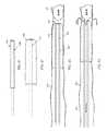
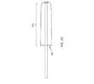
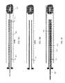
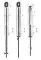
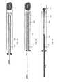
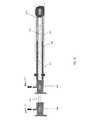
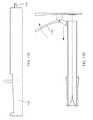
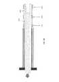
本書は一般に、医療デバイスと、これらの医療デバイスを有するシステムとを含む医療装置や、これらの医療デバイスを使用して、限定しないが凝血塊(血栓)、組織(生検、小細胞腫瘍、ポリープ、石灰化、腎臓結石など)を含む物体を回収する方法を記載する。本書記載の装置は、典型的に、内腔と、当該内腔に開口する遠位端開口とを有する細長いカテーテルを具える。カテーテルは、任意の適切な直径(例えば、<1Fr、1Fr−6Fr、1Fr−9Frなど)を有する薄型の神経血管カテーテル(例えば、マイクロカテーテル、挿入カテーテルなど)である。柔軟なトラクタアセンブリまたは部分(本書において、柔軟性トラクタチューブまたは単に柔軟性チューブと称する。)が、典型的にカテーテル内に長手方向に摺動可能に配置され、その遠位端領域(「遠位トラクタ領域」)が、カテーテルの遠位端を越えて折り返して二重になるように構成されている。柔軟性チューブ(「トラクタチューブ」)は、一般に細長く中空であり、柔軟性チューブの第1の端部がカテーテル内で近位に引っ張られたときに、前記遠位端開口部を越えてスライドし反転するよう構成されている。遠位トラクタ領域を形成する遠位端は、管状であってもなくてもよい(例えば、材料片などで形成されてもよい)。組み合わされたカテーテルと柔軟性トラクタのアセンブリはまた、ガイドワイヤを通すように構成されたカテーテルおよび柔軟性チューブを通るガイドワイヤ内腔を形成する。 This document generally uses medical devices, including medical devices and systems with these medical devices, and using these medical devices, including but not limited to blood clots (thrombus), tissues (biopsy, small cell tumors, polyps). , Mineralization, kidney stones, etc.) are described. The devices described herein typically include an elongated catheter having a lumen and a distal end opening that opens into the lumen. The catheter is a thin neurovascular catheter (eg, microcatheter, insertion catheter, etc.) having any suitable diameter (eg, <1Fr, 1Fr-6Fr, 1Fr-9Fr, etc.). A flexible tractor assembly or part (referred to herein as a flexible tractor tube or simply a flexible tube) is typically slidably disposed longitudinally within the catheter and its distal end region ("distal"). The tractor area) is configured to fold back over the distal end of the catheter and double. Flexible tubes (“tractor tubes”) are generally elongated and hollow and slide over the distal end opening when the first end of the flexible tube is pulled proximally within the catheter. It is configured to flip. The distal end forming the distal tractor region may or may not be tubular (eg, it may be formed of a piece of material or the like). The combined catheter and flexible tractor assembly also forms a guidewire lumen through the catheter and flexible tube configured to pass the guidewire.
使用時に、ガイドワイヤは、典型的にはトラクタチューブが凝血塊などの物体をカテーテルの本体内に引き入れる動作を妨害することなく、装置を通ってスライドして(例えば、装置の一部を形成してもよい)、位置決めを可能にし、いくつかの変形例では支持できるように構成されている。 In use, the guidewire typically slides through the device (eg, forming part of the device) without interfering with the movement of the tractor tube to pull objects such as blood clots into the body of the catheter. It is configured to allow positioning and support in some variants.
カテーテル内に配置され、カテーテルの遠位端で反転された、または二重になった柔軟性トラクタチューブを有するカテーテルに加えて、本書記載の装置は、これらの装置が微細血管内で、好ましくは非常に柔らかい遠位端の遠位の縁部/開口部に引っ張りモーメントを加えるにも拘わらず、特にそれらの遠位端部で潰れることなく動作可能にする1またはそれ以上の構成あるいは要素を具え得る。さらに、これらの装置は、遠位トラクタ領域を損傷させたり弱めたりすることなく、遠位トラクタ領域をカテーテル内に引き戻し、カテーテルの遠位端開口部で反転させるのに必要な力を最小限にするように適合しており、これによって装置内の柔軟性トラクタチューブの破損、拘束、自身またはカテーテルとの詰まりや絡まりといった故障モードを防止することができる。例えば、後に詳述するように、これらの装置のいずれかが、カテーテルの遠位端部またはその近傍に選択的に潤滑領域を有してもよい。カテーテルの端部は、チューブ遠位端の柔軟性トラクタ領域を反転させることができるように形成することができる。さらに、カテーテルの端部プロファイル(例えば、最も遠位の5mm、4mm、3mm、2mm、1mmなど)は、カテーテルの崩壊/座屈を防止する剛性(例えば、デュロメータ)の構成を有してもよい。代替的または追加的に、柔軟性トラクタチューブは、カテーテル内への比較的小さな力での引き込みと、カテーテルの遠位端部上での反転を実現しつつ、カテーテル周りの血管をできるだけ多く「スイープ」して血管内の物体を回収するように適合してもよい。カテーテル内のチューブの遠位部分ともいえる柔軟性チューブのトラクタ部分は、一般に、遠位の拡張可能な(第1の)端部領域を有し、これが第2の低拡張型(または非拡張型)の端部領域にすぐ隣接するか、スペーサ領域によって分離されている。第2の端部領域は、(第1の端部領域と第2の端部領域の両方がカテーテルに引き込まれた場合に)第1の端部領域に近接する。柔軟性のトラクタチューブは、カテーテルを通って近位端および/または近位ハンドルまで延在してもよいし、カテーテルの近位端の前で終端してプラーに接続されてもよい。プラーは、別の柔軟性の低いチューブ、またはワイヤ、ロッド、ストリングなどであってもよい。柔軟性トラクタチューブには、一般に、カテーテルおよび柔軟性トラクタチューブを含む装置を通過するガイドワイヤを通すことができる管腔(例えば、中心の管腔または半径方向にオフセットした管腔)を有するように構成されている。柔軟性トラクタチューブは、一般に、ガイドワイヤがこの管腔内にあるときに操作される(例えば、近位に引っ張られ、いくつかの場合には遠位に押し出される)。 In addition to catheters that are placed within the catheter and have a flexible tractor tube that is inverted or doubled at the distal end of the catheter, the devices described herein are preferably these devices within microvessels. It has one or more components or elements that allow it to operate without crushing, especially at those distal ends, despite applying a pulling moment to the distal edges / openings of the very soft distal ends. obtain. In addition, these devices minimize the force required to pull the distal tractor region back into the catheter and invert it at the distal end opening of the catheter without damaging or weakening the distal tractor region. It is adapted to prevent failure modes such as breakage, restraint, clogging or entanglement of the flexible tractor tube in the device. For example, as described in detail later, any of these devices may selectively have a lubrication region at or near the distal end of the catheter. The end of the catheter can be formed so that the flexible tractor region at the distal end of the tube can be inverted. In addition, the end profile of the catheter (eg, the most distal 5 mm, 4 mm, 3 mm, 2 mm, 1 mm, etc.) may have a stiffness (eg, durometer) configuration that prevents the catheter from collapsing / buckling. .. Alternatively or additionally, the flexible tractor tube "sweeps" as many vessels as possible around the catheter while providing relatively small force pulling into the catheter and inversion on the distal end of the catheter. It may be adapted to collect objects in the blood vessel. The tractor portion of the flexible tube, which can also be referred to as the distal portion of the tube within the catheter, generally has a distal expandable (first) end region, which is the second hypoexpandable (or non-expandable) region. ) Immediately adjacent to or separated by a spacer region. The second end region is close to the first end region (when both the first end region and the second end region are retracted into the catheter). The flexible tractor tube may extend through the catheter to the proximal end and / or the proximal handle, or may be terminated in front of the proximal end of the catheter and connected to the puller. The puller may be another inflexible tube, or wire, rod, string, or the like. Flexible tractor tubes generally have a lumen through which a guide wire passing through a device containing a catheter and a flexible tractor tube can pass (eg, a central lumen or a radial offset lumen). It is configured. Flexible tractor tubes are generally manipulated when the guidewire is within this lumen (eg, pulled proximally and in some cases extruded distally).
装置は、遠位トラクタ領域の展開および血管内での物体捕捉のために予め装填されてもよいし、いくつかの変形例では、血管内にガイドワイヤおよび/またはカテーテルを位置決めした後またはその間に、生体内に配備されてもよい。例えば、いくつかの変形例では、装置は、カテーテルが血管内に、好ましくは除去すべき物体の近くにくるまで、遠位トラクタ領域をカテーテル内に引っ込めて保持することにより、インビボでの使用に適合させることができる。一旦配置されると、カテーテル内の柔軟性チューブの遠位トラクタ領域は、カテーテルから遠位に伸ばされて拡張し、カテーテルを遠位に前進させてもさせなくても、カテーテルの遠位端上に引き出され反転されできる捕捉形状を形成する。このように、遠位トラクタ部分は、装置や身体を傷つけるリスクなしに、管腔内の必要な部位に安全かつ確実に送達することができる。 The device may be preloaded for deployment of the distal tractor region and capture of objects within the vessel, and in some variants after or during positioning of the guidewire and / or catheter within the vessel. , May be deployed in vivo. For example, in some variants, the device is used in vivo by retracting and holding the distal tractor region into the catheter until the catheter is in the blood vessel, preferably close to the object to be removed. Can be adapted. Once placed, the distal tractor region of the flexible tube within the catheter extends distally from the catheter and expands over the distal end of the catheter with or without distal advancement. It forms a trapping shape that can be pulled out and inverted. Thus, the distal tractor portion can be safely and reliably delivered to the required site within the lumen without risk of injury to the device or body.
例えば、血管から凝血塊を除去するために機械的血栓摘出を実施する方法は、カテーテルの遠位端を血管を通して凝血塊に向けて前進させるステップと、カテーテルの遠位端からカテーテル内にあるチューブの遠位トラクタ領域を露出させるステップであって、前記遠位トラクタ領域は、拡張可能な第1の端部領域と、当該拡張可能な第1の端部領域の近くのあまり拡張しない第2の端部領域とを有する、ステップと、前記拡張可能な第1の端部領域が血管内で拡張できるようにするステップと、前記遠位トラクタ領域の前記あまり拡張しない第2の端部領域と、拡張可能な第1の端部領域との間にカテーテルの遠位端領域が位置するように、カテーテルの遠位端を位置決めするステップと、前記拡張可能な第1の端部領域がカテーテルの中に引き込まれるときに、前記拡張可能な第1の端部領域がカテーテルの遠位端部上でロールすることによって凝血塊をカテーテル内に引き込むステップであって、これにより前記拡張可能な第1の端部領域が反転するステップとを具える。 For example, a method of performing mechanical thrombotomy to remove a clot from a blood vessel involves the step of advancing the distal end of the catheter through the blood vessel toward the clot and the tube in the catheter from the distal end of the catheter. A step of exposing the distal tractor region of the distal tractor region, the distal tractor region being an expandable first end region and a less dilated second near the expandable first end region. A step having an end region, a step allowing the expandable first end region to expand within the blood vessel, and the less dilated second end region of the distal tractor region. The step of positioning the distal end of the catheter so that the distal end region of the catheter is located between it and the expandable first end region, and the expandable first end region within the catheter. The expandable first end region is a step of pulling a clot into the catheter by rolling over the distal end of the catheter when pulled into the catheter, whereby the expandable first end region. It includes a step in which the end region is inverted.
前記血管を通してカテーテルの遠位端を凝血塊へと前進させるステップは、上述したようにガイドワイヤ上を前進させるステップを含むことができる。カテーテルは、ガイドワイヤ上を遠位にスライドさせるか、またはガイドワイヤとともに遠位に(または近位に)延ばすことができる。内側(トラクタ)チューブは、カテーテル内に(例えば、遠位端の近く、中間領域、または近位端の近くに)保持されてもよいし、いくつかの変形例では、カテーテルを血管内に配置した後に挿入されてもよい。カテーテルの遠位端は、除去すべき対象物(例えば、凝血塊)の近くに、または隣接して配置されてもよいし、あるいは、例えば、遠位トラクタ領域をカテーテルの遠位端から出し、カテーテル内に対象物を引き込む準備として拡張するために所定の距離だけ離されてもよい。 The step of advancing the distal end of the catheter through the blood vessel into the clot can include advancing on the guide wire as described above. The catheter can be slid distally over the guidewire or extended distally (or proximally) with the guidewire. The medial (tractor) tube may be held within the catheter (eg, near the distal end, intermediate region, or proximal end), and in some variants, the catheter is placed within the blood vessel. It may be inserted after. The distal end of the catheter may be located near or adjacent to an object to be removed (eg, a clot), or, for example, the distal tractor region may be extended from the distal end of the catheter. It may be separated by a predetermined distance in preparation for pulling the object into the catheter.
したがって、一旦位置決めされると、遠位トラクタ領域を露出させ、カテーテルの遠位端を位置決めし、いくつかの変形形態ではガイドワイヤを配置することによって装置を展開し、対象物が捕捉されてカテーテル内に引き込まれるようにすることができる。(例えば、血管に対して)遠位トラクタ領域を含む柔軟性チューブを留めながらカテーテルを近位に引っ張ることによって、および/または柔軟性チューブを遠位に延ばすことによって、遠位トラクタ領域が露出される。 Thus, once positioned, the device is deployed by exposing the distal tractor area, positioning the distal end of the catheter, and in some variants placing guidewires to capture the object and catheterize the catheter. It can be pulled in. The distal tractor region is exposed by pulling the catheter proximally while retaining the flexible tube containing the distal tractor region (eg, relative to the blood vessel) and / or by extending the flexible tube distally. To.
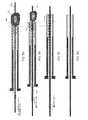
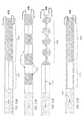
上述したように、柔軟性チューブは、拡張可能な第1の端部領域を有する遠位トラクタ領域を具えることができる。この端部領域は、一般に多孔質であり(例えば、メッシュ、編物、織物、または複数の開口部を有する固体材料を含む他の材料で形成される)、除去される対象物(例えば凝血塊)を掴むように適合される。この第1の端部領域は、カテーテル内径の約1.3倍〜約10倍(例えば、約1.5倍〜約7倍、約1.5倍〜約5倍、約1.5倍〜約4倍、約1.5倍〜約3倍など)に拡張可能である。トラクタ部分を形成するこの第1の遠位端領域は、一般に、より膨張性が低い(または実質的に拡張しない)第2の端部領域に隣接している。この第2の領域は、カテーテルの全長にわたって近位に、またはカテーテルに部分的に延びていてもよい。一般に、トラクタ部分の第1の端部領域は、カテーテルの外に露出され、凝血塊または他の物体を捕捉するために使用される。第2の端部領域は、位置決め中に露出してもよいが、さもなければ、動作中にカテーテル内に残ってもよい。 As mentioned above, the flexible tube can comprise a distal tractor region with an expandable first end region. This end region is generally porous (eg, formed of a mesh, knit, fabric, or other material, including solid materials with multiple openings) and objects to be removed (eg, clots). Fitted to grab. This first end region is about 1.3 to about 10 times the inner diameter of the catheter (eg, about 1.5 to about 7 times, about 1.5 to about 5 times, about 1.5 times to It can be expanded to about 4 times, about 1.5 times to about 3 times, etc.). This first distal end region, which forms the tractor portion, is generally adjacent to a second end region that is less expansive (or substantially non-expandable). This second region may extend proximally or partially to the catheter over the entire length of the catheter. Generally, the first end region of the tractor portion is exposed outside the catheter and is used to capture clots or other objects. The second end region may be exposed during positioning, or may remain in the catheter during operation.
このように、カテーテル内のチューブの遠位トラクタ領域をカテーテルの遠位端から露出させるステップは、遠位トラクタ領域をカテーテルの遠位端の外に延ばすか押すステップを含んでもよい。いくつかの変形例では、遠位トラクタ領域は、第1の拡張可能な遠位端領域が第2の遠位端領域上で二重になるように予形成される。他の変形形態では、第1の遠位端領域は、あまり拡張しない第2の遠位端領域に対して、遠位に、直列である。次いで、カテーテルの遠位端領域(遠位端を含む)が、遠位トラクタ領域の拡張された拡張可能な第1の端部領域とあまり拡張しない第2の端部領域との間の半径方向の間隙内に延びるように、カテーテルを遠位に移動させることができる。 Thus, the step of exposing the distal tractor region of the tube within the catheter from the distal end of the catheter may include extending or pushing the distal tractor region out of the distal end of the catheter. In some variants, the distal tractor region is preformed such that the first expandable distal end region is doubled on the second distal end region. In other variants, the first distal end region is distally in series with respect to the less dilated second distal end region. The distal end region of the catheter (including the distal end) is then radial between the expanded expandable first end region of the distal tractor region and the less dilated second end region. The catheter can be moved distally so that it extends into the gap between the catheters.
遠位トラクタ領域がカテーテルの遠位端から押し出される変形例のいずれかにおいて、例えばこの生体内での初期セットアップ段階中に、柔軟性チューブ、および特に遠位トラクタ領域が、カテーテルを拘束されることなく押し出せるように構成あるいは適合されてもよい。拡張可能なチューブがカテーテル内で拘束されると、結合拡張可能な第1の端部領域が特にカテーテルの内壁に引っかかり、展開が妨げられる。いくつかの変形例では、拡張可能な第1の端部領域は、直径約0.0005インチ〜0.005インチの約24〜144ストランドのフィラメント(例えば、ニチノール、ポリマーなど)を有するメッシュ管状部材として構成され、このメッシュ管状部材は、5cmよりも長い長さを有し、引っ張られて前記遠位端の周りで反転されるときに、縦軸の方向に約35度以下の交差ストランド間の編組角を形成し、拘束されていない場合にカテーテルの外側のカテーテルの内径の1.5倍を超える直径に拡張する。この構成の中で、管状部材は押すことができることが分かっている。 In any of the variants in which the distal tractor region is extruded from the distal end of the catheter, for example, during this initial setup phase in vivo, the flexible tube, and especially the distal tractor region, constrains the catheter. It may be configured or adapted so that it can be extruded without. When the expandable tube is constrained within the catheter, the connectable expandable first end region is particularly caught on the inner wall of the catheter, preventing deployment. In some variants, the expandable first end region is a mesh tubular member with about 24-144 strand filaments (eg, nitinol, polymer, etc.) with a diameter of about 0.0005 inches to 0.005 inches. This mesh tubular member has a length greater than 5 cm and is between intersecting strands of about 35 degrees or less in the direction of the vertical axis when pulled and flipped around the distal end. It forms a braided angle and expands to a diameter greater than 1.5 times the inner diameter of the catheter on the outside of the catheter when not constrained. In this configuration, the tubular member has been found to be pushable.
他の変形例では、拡張可能な第1の遠位端領域がカテーテルの遠位端から押し出されるか延ばされたとき、カテーテルの遠位端上で反転して拡張するように構成してもよい(例えば、予成形、形状設定など)。カテーテルは遠位に移動すると、遠位トラクタ領域のこの拡張可能な第1の端部領域を、カテーテルの外側に対して近位に押すのを補助する。 In another variant, the expandable first distal end region may be configured to flip and expand over the distal end of the catheter when extruded or extended from the distal end of the catheter. Good (eg preform, shape setting, etc.). As the catheter moves distally, it assists in pushing this expandable first end region of the distal tractor region proximally to the outside of the catheter.
これらの方法のいずれにおいても、遠位トラクタ領域は、拡張可能な第1の端部領域と、拡張可能な第1の端部領域の近くに位置する拡張性の低い第2の端部領域とを含み、拡張可能な第1の端部領域は、血管内で拡張することができる。 In any of these methods, the distal tractor region includes an expandable first end region and a less expandable second end region located near the expandable first end region. The expandable first end region can be dilated within the blood vessel.
従って、展開段階の終わりに近づくにつれて、カテーテルの遠位端部は、典型的には、カテーテルの遠位端領域が、遠位トラクタ領域のあまり拡張しない第2の端部領域と拡張可能な第1の端部領域との間に半径方向に位置するように配置され、拡張可能な第1の端部領域は、あまり拡張しない第2の端部領域上で二重にされる。 Thus, towards the end of the deployment phase, the distal end of the catheter is typically a second end region in which the distal end region of the catheter is expandable with a less dilated second end region of the distal tractor region. Arranged so as to be located radially between the one end region, the expandable first end region is doubled on the less expandable second end region.
その後、拡張可能な第1の端部領域がカテーテルの遠位端部上で引っ張られると、拡張可能な第1の端部領域が反転するように、カテーテルの遠位端部上で拡張可能な第1の端部領域をロールさせることによって、カテーテル内に対象物(すなわち凝血塊)が引き込まれる。 Then, when the expandable first end region is pulled over the distal end of the catheter, it is expandable on the distal end of the catheter so that the expandable first end region is inverted. By rolling the first end region, an object (ie, a clot) is drawn into the catheter.
上述したように、配置するステップは、カテーテルの遠位端領域が遠位トラクタ領域のあまり拡張しない第2の端部領域と拡張可能な第1の端部領域との間にあるようにカテーテルの遠位端を遠位に前進させるステップを含むことができる。 As mentioned above, the placement step of the catheter is such that the distal end region of the catheter is between the less dilated second end region of the distal tractor region and the expandable first end region. A step of advancing the distal end distally can be included.
本書記載の方法のいずれかで、ガイドワイヤを使用することができる。本明細書に記載される方法のいずれかは、血管内でガイドワイヤを凝血塊へと前進させるステップを含み、カテーテルの遠位端を前進させるステップは、カテーテルの遠位端が凝血塊に近づくまで、血管を通してカテーテルをガイドワイヤ上を前進させるステップを含む。ガイドワイヤは、凝血塊の中に挿入されてもよいし、凝血塊の直前に配置されてもよい。ガイドワイヤは凝血塊除去中に残されてもよいし、部分的または完全に最初に取り除かれてもよい。例えば、これらの方法のいずれかは、血管内でガイドワイヤを凝血塊に前進させるステップを含み、カテーテルの遠位端を前進させるステップは、カテーテルの遠位端が凝血塊に近づくまでカテーテルをガイドワイヤ上で凝血塊に向けて前進させるステップを含み、カテーテル内へ凝血塊を引き込むステップは、拡張可能な第1の端部領域をカテーテルの遠位端上でロールさせながら、カテーテルを凝血塊の方へ前進させるステップを含んでもよい。 Guide wires can be used by any of the methods described in this document. One of the methods described herein includes the step of advancing the guide wire into the clot in the blood vessel, and the step of advancing the distal end of the catheter causes the distal end of the catheter to approach the clot. Includes the step of advancing the catheter over the guidewire through the blood vessel. The guide wire may be inserted into the clot or placed just before the clot. The guide wire may be left during clot removal or may be partially or completely removed first. For example, one of these methods involves advancing the guide wire into the clot in the blood vessel, and advancing the distal end of the catheter guides the catheter until the distal end of the catheter approaches the clot. The step of pulling the clot into the catheter, including advancing towards the clot on the wire, rolls the catheter over the distal end of the catheter while rolling the expandable first end region of the clot. It may include steps to move forward.
凝血塊をカテーテル内に引き込むステップは、一般に、遠位トラクタ領域(例えば、拡張可能な第1の端部領域)をカテーテルの遠位端上でロールさせるステップを含む。装置はまた、遠位トラクタ領域の作動中に遠位に移動されてもよい。例えば、凝血塊をカテーテル内に引き込むステップは、カテーテルを遠位に前進させながらチューブを近位に(遠位端に沿って遠位のトラクタ領域を回転させるために)引き戻すステップおよび/またはチューブを近位に引き出すステップを含むことができる。 The step of pulling the clot into the catheter generally involves rolling the distal tractor region (eg, the expandable first end region) over the distal end of the catheter. The device may also be moved distally during operation of the distal tractor region. For example, the step of pulling a clot into a catheter is a step of pulling the tube proximally (to rotate the distal tractor region along the distal end) while advancing the catheter distally and / or the tube. It can include a step of pulling out proximally.
これらの方法のいずれにおいても、凝血塊をカテーテル内に引き込むステップは、カテーテルを遠位に前進させながらチューブを近位に引き戻すステップを含み、ここでチューブは、カテーテルが前進される速度とは異なる速度で引き戻してもよい。いくつかの構成では、チューブ(遠位トラクタ領域)が近位に引き戻されるよりも速くカテーテルを遠位に前進させることが有益であり得る。いくつかの変形例では、カテーテルは、チューブ(遠位トラクタ領域)が近位に引き戻されるよりもゆっくりと前進されてもよい。あるいは、いくつかの変形例では、それらは同じ速度で移動される。この移動速度は、カテーテル内の近位方向の動き(例えば、第2の端部領域)を見ることによって柔軟性チューブについて決定されてもよい。 In any of these methods, the step of pulling the clot into the catheter involves pulling the tube proximally while advancing the catheter distally, where the tube is different from the rate at which the catheter is advanced. You may pull back at speed. In some configurations, it may be beneficial to advance the catheter distally faster than the tube (distal tractor region) is pulled back proximally. In some variants, the catheter may be advanced more slowly than the tube (distal tractor region) is pulled back proximally. Alternatively, in some variants, they are moved at the same speed. This rate of movement may be determined for the flexible tube by looking at the proximal movement within the catheter (eg, the second end region).
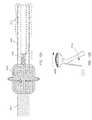
一般に、遠位トラクタ領域の拡張可能な第1の端部領域は拡張可能であり、凝血塊のような物体と係合可能な遠位方向に向いた口またはリップを形成する。拡張可能なトラクタ領域のリップの口は、(図18、21Dを参照してより詳細に後述するように)カテーテル外径(OD)の長軸に対して5°〜60°、好ましくは10°以上(例えば、10°〜60°、10°〜50°、10°〜45°など)の範囲内の接線角度またはロール角を形成してもよい。チューブがカテーテルの中に引き込まれた状態でロール角が少なくとも10度である限り、チューブはカテーテル先端で詰まったりつっかえたりすることがない。メッシュチューブは、10度を超えるロール角を確保するために剛性を変更することによって構成することができる。代替的に、または最小のロール角を維持することと組み合わせて、(図18で詳細に後述するように)カテーテルの最遠位端におけるチューブ材料IDとカテーテルODとの間の物理的空間またはギャップを維持することが望ましい。チューブが引き戻されたときにカテーテルの遠位端の周りでチューブがロールするように、このギャップは、例えば、0.1mm、0.2mm、0.3mm、0.4mm、0.5mm、0.7mm、0.8mm、0.9mm、1.0mmなどより大きくする必要があり得る。拡張された材料(例えば、メッシュ、織物、編組、ニット、穿孔された材料など)は、血管内で単独で拡張することができる。従って、拡張可能な第1の領域は、自己拡張可能であってもよい。遠位トラクタ領域の拡張可能な第1の端部領域は、拡張するように予めバイアスされていてもよい。いくつかの変形例では、形状記憶材料(例えば、形状記憶合金)が使用される。いくつかの変形例では、付勢要素が、拡張可能な第1の端部領域に含まれるか、一体化されて、遠位のトラクタ領域が拡張される。拡張可能な第1の端部領域は、血管の内膜と接触するように拡張してもよい。いくつかの変形例では、遠位トラクタ領域の最遠位端が血管と接触するように装置を構成してもよい(例えば、拡張可能な第1の端部領域を寸法形成することを含む)。したがって、本書記載の変形例のいずれも、付加的または代替的に、拡張可能な遠位端領域を開いて拡開させる半径方向の力を増大させることにより血管と接触させるための、ループ、リング、足場などの付勢要素を具えてもよい。いくつかの変形例では、この拡開する付勢力(ループ、ヘリックス、リングなど)は、遠位トラクタ領域の拡張可能な第1の端部領域の遠位端に、またはその近くに配置される。 In general, the expandable first end region of the distal tractor region is expandable, forming a distally oriented mouth or lip that can engage an object such as a clot. The lip mouth of the expandable tractor region is 5 ° to 60 °, preferably 10 °, relative to the long axis of the catheter outer diameter (OD) (as described in more detail with reference to FIGS. 18, 21D). A tangential angle or a roll angle within the above range (for example, 10 ° to 60 °, 10 ° to 50 °, 10 ° to 45 °, etc.) may be formed. As long as the tube is retracted into the catheter and the roll angle is at least 10 degrees, the tube will not clog or stall at the tip of the catheter. The mesh tube can be configured by varying the stiffness to ensure a roll angle greater than 10 degrees. Alternatively, or in combination with maintaining a minimum roll angle, the physical space or gap between the tube material ID and the catheter OD at the distal end of the catheter (as described in detail in FIG. 18). It is desirable to maintain. This gap is, for example, 0.1 mm, 0.2 mm, 0.3 mm, 0.4 mm, 0.5 mm, 0., so that the tube rolls around the distal end of the catheter when the tube is pulled back. It may need to be larger than 7 mm, 0.8 mm, 0.9 mm, 1.0 mm and the like. The expanded material (eg, mesh, fabric, braid, knit, perforated material, etc.) can be expanded independently within the blood vessel. Therefore, the expandable first region may be self-expandable. The expandable first end region of the distal tractor region may be pre-biased to expand. In some variants, shape memory materials (eg, shape memory alloys) are used. In some variants, the urging element is included or integrated into the expandable first end region to expand the distal tractor region. The expandable first end region may be expanded to contact the intima of the blood vessel. In some variations, the device may be configured such that the most distal end of the distal tractor region is in contact with the blood vessel (eg, including sizing the expandable first end region). .. Thus, in any of the variants described herein, additional or alternative, loops, rings for contacting blood vessels by increasing the radial force to open and dilate the expandable distal end region. , Scaffolding and other urging elements may be provided. In some variants, this expanding urging force (loop, helix, ring, etc.) is placed at or near the distal end of the expandable first end region of the distal tractor region. ..
本書記載の変形例のいずれも、拡張可能なカテーテル先端を含むことができる。例えば、いくつかの変形例では、カテーテル先端のデュロメータは十分に柔らかく、遠位トラクタ領域がカテーテル内に近位に引き込まれたときに近位方向に圧縮し、この遠位先端を軸方向に圧縮することにより、遠位端部をわずかに拡張させる(例えば、フレア状に広がる)。 Any of the variants described herein can include an expandable catheter tip. For example, in some variants, the catheter tip durometer is soft enough to compress proximally when the distal tractor region is pulled proximally into the catheter, compressing this distal tip axially. By doing so, the distal end is slightly dilated (eg, flared).
上述したように、カテーテル内のチューブの遠位トラクタ領域をカテーテルの遠位端から露出させるステップは、遠位トラクタ領域をカテーテルの遠位端から押し出すステップを含んでもよい。代替的または追加的に、カテーテルの遠位端からカテーテル内にあるチューブの遠位トラクタ領域を露出させるステップは、カテーテルを近位に引くステップを含んでもよい。例えば、カテーテル内のチューブの遠位トラクタ領域をカテーテルの遠位端から露出させるステップは、遠位トラクタ領域をカテーテルの遠位端から押し出して、あまり拡張しない第2の端部領域の上に反転された拡張可能な第1の端部領域を露出させるステップを含んでもよい。 As mentioned above, the step of exposing the distal tractor region of the tube within the catheter from the distal end of the catheter may include the step of pushing the distal tractor region out of the distal end of the catheter. Alternatively or additionally, the step of exposing the distal tractor region of the tube within the catheter from the distal end of the catheter may include the step of pulling the catheter proximally. For example, the step of exposing the distal tractor region of a tube within a catheter from the distal end of the catheter pushes the distal tractor region out of the distal end of the catheter and flips over a second end region that does not expand much. It may include a step of exposing the extended expandable first end region.
いくつかの変形例では、カテーテル内のチューブの遠位トラクタ領域をカテーテルの遠位端から露出させるステップは、拡張可能な第1の端部領域をカテーテルの遠位端部から延ばし、拡張可能な第1の端部領域が延びるのに伴い拡張可能な第1の端部領域がカテーテルの遠位端上で反転するようにするステップを含んでもよい。 In some variants, the step of exposing the distal tractor region of the tube within the catheter from the distal end of the catheter extends the expandable first end region from the distal end of the catheter and is expandable. It may include a step of causing the expandable first end region to flip over the distal end of the catheter as the first end region extends.
遠位トラクタ領域の拡張可能な第1の端部領域は、任意の適切な長さとすることができ、この長さの任意の部分(その全て、90%、80%、70%、60%、50%、40%など)がこのセットアップ時に露出されていてもよい。例えば、いくつかの変形例では、チューブの遠位トラクタ領域を露出させるステップは、拡張可能な第1の端部の少なくとも5mmを露出させるステップを含むことができる。拡張可能な第1の端部領域は、例えば、5mm以上(例えば、6、7、8、9、10、11、12、13、14、15、16、17、18、19、20、25、30、35、40、45、50、55、60、70、80、90、100、110、120、130、140、150、200、300、400、500mmなど、約5mm〜約500mmの間、いずれかの低い値5、6、7、8、9、10、11、12、13、14、15、16、17、18、19、20、25、30、35、40、45、50、55、60、70、80、90、100、110、120、130、140、150、200mmと、いずれかの大きな値10、11、12、13、14、15、16、17、18、19、20、25、30、35、40、45、50、55、60、70、80、90、100、110、120、130、140、150、200、300、400、500mmの間、ここで低い値は常に大きな値より小さい)である。これらの変形のいずれにおいても、遠位トラクタ領域を露出させる場合、拡張可能な第1の遠位端領域のみがカテーテルから露出されてもよいし(例えば、拡張可能な遠位端領域を遠位に押し出し、カテーテルの遠位端上で反転するようにする)、拡張可能な第1の遠位端領域およびあまり拡張しない第2の遠位端領域の両方が、すべてまたは部分的に露出してもよい。例えば、少なくとも1cmの拡張可能な第1の端部領域と、少なくとも1cmのあまり拡張しない第2の端部領域とを露出させる。拡張可能な第1の端部領域は、拡張しにくい第2の端部領域にわたって反転されて(折り返されて)もよい。 The expandable first end region of the distal tractor region can be of any suitable length and any portion of this length (all of which 90%, 80%, 70%, 60%, 50%, 40%, etc.) may be exposed during this setup. For example, in some variants, the step of exposing the distal tractor region of the tube can include the step of exposing at least 5 mm of the expandable first end. The expandable first end region is, for example, 5 mm or more (eg, 6,7,8,9,10,11,12,13,14,15,16,17,18,19,20,25, 30, 35, 40, 45, 50, 55, 60, 70, 80, 90, 100, 110, 120, 130, 140, 150, 200, 300, 400, 500 mm, etc., between about 5 mm and about 500 mm. The
上述したように、拡張可能な第1の端部領域は、拡張可能であって物体(例えば、凝血塊)を把持することができる任意の適切な材料を含むことができる。例えば、遠位トラクタ領域の拡張可能な第1の端部領域は、あまり拡張しない第2の端部領域に隣接して結合されたメッシュを含んでもよい。例えば、拡張可能な第1端部領域は、織物材料、メッシュ編組材料、編み材料、または複数の開口部を有するフィルム材料のうちの1つ以上であってもよい。あまり拡張しない第2の端部領域は、同じ材料で作ることができ、または異なる材料で作ることができる。あまり拡張しない第2の端部領域は、同じ構造(例えば、織物など)であってもよいし、異なる構造を有してもよく、これには拡張可能な第1の端部領域の構造をあまり拡張しないようにしたバリエーションを含む。例えば、あまり拡張しない第2の端部領域は、非多孔質(例えば、不織、非編物または無垢材料など)またはより弱多孔性(例えば、きつく織られた、小さな孔サイズの編み穴、きつく編まれた)であってもよい。いくつかの変形例では、拡張性の低い第2の端部領域は、拡張可能な第1の端部領域(例えば、中間の拡張性を有する)と拡張可能でない第2の端部領域との間の移行領域を含んでもよい。一般に、遠位トラクタ領域のあまり拡張しない第2の端部領域は、拡張可能でない構造および材料を含む。 As mentioned above, the expandable first end region can include any suitable material that is expandable and capable of gripping an object (eg, a clot). For example, the expandable first end region of the distal tractor region may include a mesh coupled adjacent to a less dilated second end region. For example, the expandable first end region may be one or more of a woven material, a mesh braided material, a knitted material, or a film material having a plurality of openings. The less expansive second end region can be made of the same material or of different materials. The less expandable second end region may have the same structure (eg, woven fabric, etc.) or may have different structures, which may include the structure of the expandable first end region. Includes variations that are not extended too much. For example, the less expansive second end region is non-porous (eg, non-woven, non-knitted or solid material, etc.) or less porous (eg, tightly woven, small hole-sized braided holes, tight. It may be woven). In some variants, the less extensible second end region is the expandable first end region (eg, having intermediate expandability) and the non-extensible second end region. It may include a transition area between them. In general, the less dilated second end region of the distal tractor region contains non-expandable structures and materials.
血管から凝血塊を除去するために機械的な血栓摘出を行う方法は、カテーテルの遠位端を血管を通して凝血塊に向けて前進させるステップと、カテーテルの遠位端からカテーテル内にあるチューブの遠位トラクタ領域を露出させるステップであって、前記遠位トラクタ領域は、拡張可能な第1の端部領域と、当該拡張可能な第1の端部領域の近くのあまり拡張しない第2の端部領域とを有し、前記拡張可能な第1の端部領域が前記あまり拡張しない第2の端部領域の上に反転された構成であるステップと、前記拡張可能な第1の端部領域が血管内で拡張できるようにするステップであって、前記カテーテルの遠位端領域が、前記遠位トラクタ領域の前記あまり拡張しない第2の端部領域と前記拡張可能な第1の端部領域との間にあるようにするステップと、前記カテーテルを遠位に前進させるとともに前記チューブを前記カテーテル内で近位に引き戻すことによって凝血塊をカテーテル内に引き込むステップであって、前記拡張可能な第1の端部領域がカテーテルの中に引き込まれるときに、前記拡張可能な第1の端部領域がカテーテルの遠位端部上でロールして反転するステップとを具えることを特徴とする。 Mechanical thrombotomy to remove a clot from a blood vessel involves the step of advancing the distal end of the catheter through the blood vessel towards the clot and the distance of the tube within the catheter from the distal end of the catheter. In the step of exposing the catheter region, the distal tractor region is an expandable first end region and a less dilated second end region near the expandable first end region. A step having a region and the expandable first end region inverted over the less expandable second end region and the expandable first end region In the step of allowing dilation within a blood vessel, the distal end region of the catheter comprises the less dilated second end region and the dilatable first end region of the distal tractor region. A step of pulling the clot into the catheter by advancing the catheter distally and pulling the tube proximally within the catheter, the first expandable. It is characterized by comprising a step of rolling and reversing the expandable first end region over the distal end of the catheter as the end region of the catheter is pulled into the catheter.
上述したように、拡張可能な第1の端部領域は、遠位のトラクタ領域を露出させる前に、あまり拡張しない第2の端部領域の上で反転されてもよい。あるいは、遠位トラクタ領域を露出させるステップは、遠位トラクタ領域が露出されるのに伴い、拡張可能な遠位端領域をあまり拡張しない第2の端部領域の上に反転させるステップを含んでもよい。一般に、カテーテル内の管の遠位トラクタ領域をカテーテルの遠位端から露出させるステップは、遠位トラクタ領域をカテーテルの遠位端から押し出すステップを含んでもよい。カテーテル内の管の遠位トラクタ領域をカテーテルの遠位端から露出させるステップは、カテーテルを近位に引くステップを含んでもよい。 As mentioned above, the expandable first end region may be flipped over a less dilated second end region before exposing the distal tractor region. Alternatively, the step of exposing the distal tractor region may include flipping the expandable distal end region over a second end region that is less dilated as the distal tractor region is exposed. Good. In general, the step of exposing the distal tractor region of the tube within the catheter from the distal end of the catheter may include pushing the distal tractor region out of the distal end of the catheter. The step of exposing the distal tractor region of the tube within the catheter from the distal end of the catheter may include the step of pulling the catheter proximally.
血管から凝血塊を除去するために機械的な血栓摘出を行う方法は、カテーテルの遠位端を血管を通して凝血塊に向けて前進させるステップと、カテーテルの遠位端からカテーテル内にあるチューブの遠位トラクタ領域を露出させるステップであって、前記遠位トラクタ領域は、拡張可能な第1の端部領域と、あまり拡張しない第2の端部領域とを有し、前記拡張可能な第1の端部領域を前記カテーテルの遠位端から外に延ばし、その結果、前記拡張可能な第1の端部領域が延びるにつれて前記拡張可能な第1の端部領域が前記カテーテルの遠位端部上で反転する、露出させるステップと、前記拡張可能な第1の端部領域が前記カテーテルの遠位端から外に延びるにつれて血管内で拡張できるようにするステップであって、前記カテーテルの遠位端領域が、前記あまり拡張しない第2の端部領域と前記拡張可能な第1の端部領域との間にあるようにするステップと、前記チューブを前記カテーテル内で近位に引き戻すことによって凝血塊をカテーテル内に引き込むステップであって、これにより前記拡張可能な遠位端部領域がカテーテルの中に引き込まれるときに、前記拡張可能な遠位端部領域がカテーテルの遠位端部上でロールし、潰れ、反転するステップとを具えることを特徴とする。カテーテルの遠位端からカテーテル内にあるチューブの遠位トラクタ領域を露出させるステップは、遠位トラクタ領域をカテーテルの遠位端から押し出すステップを含んでもよい。代替的または追加的に、カテーテル内のチューブの遠位トラクタ領域をカテーテルの遠位端から露出させるステップは、チューブの遠位トラクタ領域に対してカテーテルを近位に引き出すステップを含んでもよい。 Mechanical thrombotomy to remove a clot from a blood vessel involves the step of advancing the distal end of the catheter through the blood vessel toward the clot and the distance of the tube within the catheter from the distal end of the catheter. In the step of exposing the catheter region, the distal tractor region has an expandable first end region and a less expandable second end region, the expandable first end region. The end region extends outward from the distal end of the catheter so that as the expandable first end region extends, the expandable first end region extends over the distal end of the catheter. Inverted with, and exposed, and allowing the expandable first end region to expand intravascularly as it extends outward from the distal end of the catheter, the distal end of the catheter. A clot by pulling the tube proximally within the catheter, with the step of ensuring that the region is between the less dilated second end region and the expandable first end region. Is a step of pulling into the catheter, whereby the expandable distal end region rolls over the distal end of the catheter as the expandable distal end region is pulled into the catheter. It is characterized by having steps of crushing, crushing, and reversing. The step of exposing the distal tractor region of the tube within the catheter from the distal end of the catheter may include pushing the distal tractor region out of the distal end of the catheter. Alternatively or additionally, the step of exposing the distal tractor region of the tube within the catheter from the distal end of the catheter may include pulling the catheter proximal to the distal tractor region of the tube.
血管から凝血塊を除去するための機械的血栓摘出装置が本明細書に記載されており、該装置は、遠位端および遠位端開口を有するカテーテルであって、内径および外径を有するカテーテルと、カテーテル内のチューブの遠位トラクタ領域であって、拡張可能な遠位端領域と、前記拡張可能な遠位端領域の近位に位置する、あまり拡張しない遠位端領域とを有し、前記拡張可能な遠位端領域が、あまり拡張しない遠位端領域の上で反転される、遠位トラクタ領域と、前記遠位トラクタ領域を含む前記カテーテルおよび前記チューブを通るガイドワイヤ管腔であって、ガイドワイヤを通すように構成されたガイドワイヤ管腔と、前記チューブに連結され、前記遠位トラクタ領域が前記カテーテルの内径内から解放されるように、前記カテーテルと前記チューブとの間の相対運動を生じさせるように構成された近位ハンドルとを具え、前記拡張可能な遠位端領域は、カテーテルが拡張可能な遠位端領域とあまり拡張しない遠位端領域との間を前進することができるように、その外径よりも大きな直径に拡張可能であり、前記チューブが近位に引き込まれると拡張可能な遠位端領域をカテーテルの遠位端の上を引っ張り、これにより前記拡張可能な遠位端領域がカテーテルの遠位端内へとロールし、反転し、潰れて、カテーテル内に引き込まれることを特徴とする。 A mechanical thrombotomy device for removing clots from blood vessels is described herein, which is a catheter with distal and distal end openings, with inner and outer diameters. And a distal tractor region of the tube within the catheter, having an expandable distal end region and a less dilated distal end region located proximal to the divisible distal end region. In the distal tractor region, the distal tractor region, and the guidewire lumen through the catheter and the tube containing the distal tractor region, where the expandable distal end region is inverted over a less dilated distal end region. Between the catheter and the tube so that there is a guidewire cavity configured to pass the guidewire and is connected to the tube and the distal tractor region is released from within the inner diameter of the catheter. With a proximal handle configured to produce relative movement of the catheter, the expandable distal end region advances between the distal end region where the catheter is expandable and the distal end region where it is less dilated. It is extensible to a diameter greater than its outer diameter so that it can be expanded and pulled over the distal end of the catheter, thereby pulling the extensible distal end region over the distal end of the catheter. The expandable distal end region rolls into the distal end of the catheter, flips, collapses, and is drawn into the catheter.
例えば、血管から凝血塊を除去するための機械的血栓摘出装置は、遠位端および遠位端開口を有するカテーテルであって、内径および外径を有するカテーテルと、カテーテル内の遠位トラクタ領域を有するチューブであって、遠位トラクタ領域が、拡張可能な遠位端領域と、当該拡張可能な先端領域の近くにあるあまり拡張しない遠位端領域とを具え、前記拡張可能な遠位端領域は、カテーテルの遠位端から露出されるにしたがって前記あまり拡張しない遠位端領域の上に反転するように付勢されているチューブと、前記遠位トラクタ領域を含むカテーテルおよびチューブを通るガイドワイヤ管腔であって、ガイドワイヤを通すように構成されたガイドワイヤ管腔と、前記チューブに連結され、前記遠位トラクタ領域が前記カテーテルの内径内から解放されるように、前記カテーテルと前記チューブとの間の相対運動を生じさせるように構成された近位ハンドルとを具え、前記拡張可能な遠位端領域は、前記外径より大きな直径へと拡張可能であり、前記チューブは近位に引き込まれるとカテーテルの遠位端上を前記拡張可能な遠位端領域を引っ張って、前記拡張可能な遠位端領域がカテーテルの遠位端内へとロールし、反転し、潰れ、カテーテル内に引き込まれることを特徴とする。 For example, a mechanical thrombectomy device for removing clots from blood vessels is a catheter with distal and distal end openings that has inner and outer diameters and a distal tractor region within the catheter. A tube having an expandable distal end region, wherein the distal tractor region comprises an expandable distal end region and a less dilated distal end region near the expandable distal end region. Is a tube urged to flip over the less dilated distal end region as exposed from the distal end of the catheter, and a guide wire through the catheter and tube containing the distal tractor region. The catheter and the tube so that the catheter and the tube are connected to the tube and the distal tractor region is released from within the inner diameter of the catheter, which is the lumen and is configured to pass the guide wire. The extensible distal end region is extensible to a diameter greater than the outer diameter and the tube is proximal, with a proximal handle configured to produce relative movement between and. When retracted, the expandable distal end region pulls over the distal end of the catheter, causing the expandable distal end region to roll into the distal end of the catheter, flip, collapse, and into the catheter. It is characterized by being drawn in.
また、本書では、機械的血栓摘出装置が一般的に記載されている。例えば、血管から凝血塊を除去するための機械的血栓摘出装置であって、遠位端および遠位端開口を有するカテーテルと、当該カテーテル内に延在しカテーテルの遠位端の上で折り返される柔軟性チューブであって、前記柔軟性チューブの第1の端部が前記カテーテル内で近位に引っ張られると前記遠位端口上で摺動して反転するように構成された柔軟性チューブと、ガイドワイヤを通すように構成された、カテーテルおよび柔軟性チューブを通るガイドワイヤ管腔とを具えることを特徴とする。 Also, in this document, a mechanical thrombectomy device is generally described. For example, a mechanical thrombectomy device for removing a clot from a blood vessel, with a catheter having distal and distal end openings and a catheter that extends within the catheter and folds over the distal end of the catheter. A flexible tube that is configured to slide and invert on the distal end opening when the first end of the flexible tube is pulled proximally within the catheter. It comprises a catheter and a guidewire lumen through a flexible tube configured to pass a guidewire.
血管から凝血塊を除去するための機械的血栓摘出装置は、遠位端および遠位端開口を有するカテーテルであって、前記遠位端開口は、前記遠位端に直近の領域のデュロメータよりも高いデュロメータを有し、さらに、前記遠位端開口が丸いリッププロファイルを有するカテーテルと、前記カテーテル内に延在して当該カテーテルの遠位端上で折り返される柔軟性チューブであって、柔軟性チューブの第1の端部がカテーテル内で近位に引っ張られると遠位端開口の上で反転されるように構成された柔軟性チューブと、前記カテーテルおよび前記柔軟性チューブを貫通し、ガイドワイヤを通すように構成されたガイドワイヤ管腔とを具えることを特徴とする。カテーテル遠位端のデュロメータは、60Aショア硬度よりも大きいか、または40Dショア硬度よりも高くてもよい。 A mechanical thrombectomy device for removing a clot from a blood vessel is a catheter having a distal end and a distal end opening, the distal end opening being more than a durometer in the area closest to the distal end. A flexible tube that has a high durometer and also has a lip profile with a rounded distal end opening and a flexible tube that extends into the catheter and folds over the distal end of the catheter. A flexible tube configured to flip over the distal end opening when the first end of the catheter is pulled proximally within the catheter, and a guide wire that penetrates the catheter and the flexible tube. It is characterized by having a guide wire cavity configured to pass through. The durometer at the distal end of the catheter may be greater than 60A shore hardness or greater than 40D shore hardness.
血管から凝血塊を除去するための機械的血栓摘出装置は、遠位端および遠位端開口を有する内側カテーテルと、前記カテーテルを通って延在して当該内側カテーテルの遠位端上で折り返される柔軟性チューブであって、前記柔軟性チューブの第1の端部が前記内側カテーテル内で近位に引っ張られると前記遠位端開口上で反転するように構成されている柔軟性チューブと、前記内側カテーテルと柔軟性チューブの上に延在する外側カテーテルと、前記外側カテーテルの遠位端と前記内側カテーテルの遠位端開口との間に延在する前記柔軟性チューブの潤滑領域とを具え、前記柔軟性チューブの大部分は滑らかではなく、前記カテーテルおよび前記柔軟性チューブを貫通し、ガイドワイヤを通すように構成されたガイドワイヤ管腔とを具えることを特徴とする。 A mechanical thrombectomy device for removing a clot from a blood vessel is an inner catheter with distal and distal ends openings that extends through the catheter and folds over the distal end of the inner catheter. A flexible tube comprising a flexible tube configured such that the first end of the flexible tube flips over the distal end opening when pulled proximally within the medial catheter. An outer catheter extending over the inner catheter and the flexible tube and a lubricating region of the flexible tube extending between the distal end of the outer catheter and the distal end opening of the inner catheter. Most of the flexible tubes are not smooth and are characterized by including a catheter and a guidewire lumen configured to penetrate the flexible tube and pass a guidewire.
血管から凝血塊を除去するための機械的血栓摘出装置は、遠位端および遠位端開口を有する内側カテーテルと、前記カテーテルを通って延在して当該内側カテーテルの遠位端上で折り返される柔軟性チューブであって、前記柔軟性チューブの第1の端部が前記内側カテーテル内で近位に引っ張られると前記遠位端開口上で反転するように構成されている柔軟性チューブと、前記柔軟性チューブと前記カテーテルの外面との間の解放可能なアタッチメントであって、柔軟性チューブが(例えば0.01Nより大きい)所定の力で引っ張られたときに解放するように構成されたアタッチメントと、前記カテーテルおよび前記柔軟性チューブを貫通し、ガイドワイヤを通すように構成されたガイドワイヤ管腔とを具えることを特徴とする。 A mechanical thrombectomy device for removing a clot from a blood vessel is an medial catheter with distal and distal end openings that extends through the catheter and folds over the distal end of the medial catheter. A flexible tube comprising a flexible tube configured such that a first end of the flexible tube flips over the distal end opening when pulled proximally within the medial catheter. A releasable attachment between the flexible tube and the outer surface of the catheter that is configured to relieve when the flexible tube is pulled with a given force (eg, greater than 0.01 N). , The catheter and the flexible tube are provided with a guide wire lumen configured to penetrate and pass a guide wire.
血管から凝血塊を除去するための機械的血栓摘出装置は、遠位端、遠位端開口および内径を有するカテーテルと、前記カテーテルを通って延在して当該内側カテーテルの遠位端上で折り返される柔軟性チューブであって、前記柔軟性チューブの第1の端部が前記内側カテーテル内で近位に引っ張られると前記遠位端開口上で反転するように構成され、柔軟性チューブが前記遠位端開口上で反転するのに十分な力でカテーテル内で近位に引っ張られたときに、前記カテーテルの内径の半分より大きな直径を有するように、前記柔軟性チューブが低いポアソン比を有する柔軟性チューブと、前記カテーテルおよび前記柔軟性チューブを貫通し、ガイドワイヤを通すように構成されたガイドワイヤ管腔とを具えることを特徴とする。ポアソン比が低い柔軟性チューブは、0.5未満であってもよいし、0.05〜0.5または0.1〜0.3の範囲であってもよい。 A mechanical thrombectomy device for removing a clot from a blood vessel includes a catheter having a distal end, a distal end opening and an inner diameter, extending through the catheter and folded over the distal end of the medial catheter. The flexible tube is configured to flip over the distal end opening when the first end of the flexible tube is pulled proximally within the medial catheter so that the flexible tube is distant. The flexibility tube has a low Poisson ratio so that it has a diameter greater than half the inner diameter of the catheter when pulled proximally within the catheter with sufficient force to flip over the distal opening. It is characterized by comprising a sex tube and a guidewire lumen that penetrates the catheter and the flexible tube and is configured to pass a guidewire. Flexible tubes with a low Poisson's ratio may be less than 0.5, and may be in the range of 0.05 to 0.5 or 0.1 to 0.3.
既に上述したように、柔軟性チューブは、典型的には、拡張可能な第1の端部領域と、第1の端部領域の近位に隣接する、あまり拡張しない(または非拡張可能な)第2の端部領域とを有する遠位トラクタ領域を具える。したがって、柔軟性チューブは、メッシュチューブを含むことができる。 As already mentioned above, the flexible tube is typically less expandable (or non-expandable) adjacent to the expandable first end region and proximal to the first end region. It comprises a distal tractor region with a second end region. Therefore, the flexible tube can include a mesh tube.
一般に、本書記載の装置の一部を構成するカテーテルは、例えば神経血管用カテーテルにより取られる蛇行経路に適するように、非常に柔軟性がある。いくつかの変形例では、組み立てられた装置(遠位端の上を柔軟性チューブが覆い、運用準備ができている)の集合剛性は、柔軟性チューブを有さないカテーテルの本来の剛性の所定のパーセンテージである(例えば、10%以内、12%以内、15%以内、16%以内、17%以内、18%以内、19%以内、20%以内、25%以内、30%以内など)。例えば、カテーテルを通って延在しカテーテルの遠位端上で折り返された柔軟性チューブは、カテーテルの遠位5cmの剛性を、カテーテルを通って延在しカテーテルの遠位端上で折り返された柔軟性チューブのないカテーテルの遠位5cmの剛性の所定の割合(例えば、15%)未満まで増大させることができる。 In general, the catheters that form part of the devices described herein are highly flexible, for example, to suit the meandering pathways taken by neurovascular catheters. In some variants, the collective stiffness of the assembled device (the flexible tube covers the distal end and is ready for operation) determines the intrinsic stiffness of the catheter without the flexible tube. (For example, within 10%, within 12%, within 15%, within 16%, within 17%, within 18%, within 19%, within 20%, within 25%, within 30%, etc.). For example, a flexible tube that extends through the catheter and folds over the distal end of the catheter has a stiffness of 5 cm distal to the catheter that extends through the catheter and folds over the distal end of the catheter. It can be increased to less than a predetermined percentage (eg, 15%) of stiffness 5 cm distal to a catheter without a flexible tube.
本明細書に記載されたいずれの変形例においても、柔軟性チューブの遠位トラクタ領域は、例えば凝血塊などの物体を掴むように適合される。特に、柔軟性チューブは、多孔質であってもよいし、所定の幅(例えば、約0.005インチ)未満の細孔間の縦方向の分離を有する細孔パターンを有する少なくとも1つの多孔性部分を有してもよい。この実施例で使用される場合の「孔」は、メッシュ(織り目など)のストランド間の窓、開口部、隙間、ならびにソリッドシートに貫通形成される孔を含む。一般に、織られた(特に編組された)拡張可能な第1の端部領域の材料の場合、より小さいフィラメントが掴むのに好適であり、したがって、孔のサイズがより小さい方が好ましい。最適寸法は、フィラメントのサイズ、細孔のパーセンテージ、細孔の間隔のサイズ、細孔の直径などを含む材料に依存する。例えば、いくつかの変形例では、間隙率は、60%より大きく(70%超、75%超、80%超、85%超など、60〜95、65〜95、70〜95%など)、繊維直径(織布材料の場合)は0.005未満である。凝血物または異物を確実に掴むのに必要な柔軟性チューブ部材の有効孔径は、50〜1000マイクロメートル(μm)、または100〜200μm、100〜300μm、100〜500μmまたは500〜1000μmの範囲である。柔軟性チューブ部材は、その長さに沿って細孔サイズが変化してもよい。 In any of the modifications described herein, the distal tractor region of the flexible tube is adapted to grab an object, such as a clot. In particular, the flexible tubing may be porous and at least one porous having a pore pattern with longitudinal separation between pores less than a predetermined width (eg, about 0.005 inch). It may have a portion. As used in this embodiment, "holes" include windows, openings, gaps between strands of mesh (such as weaves), as well as holes formed through the solid sheet. In general, for woven (especially braided) expandable first end region materials, smaller filaments are suitable for gripping, and therefore smaller hole sizes are preferred. Optimal dimensions depend on the material, including filament size, pore percentage, pore spacing size, pore diameter, and so on. For example, in some variants, the porosity is greater than 60% (more than 70%, more than 75%, more than 80%, more than 85%, etc., 60-95, 65-95, 70-95%, etc.). The fiber diameter (in the case of woven fabric material) is less than 0.005. The effective pore size of the flexible tube member required to reliably grab a clot or foreign body is in the range of 50 to 1000 micrometers (μm), or 100 to 200 μm, 100 to 300 μm, 100 to 500 μm, or 500 to 1000 μm. .. The pore size of the flexible tube member may change along its length.
一般に、本明細書で使用されるように、織物材料は、材料の複数のストランドを交絡パターン(例えば、交絡のストランド、フィラメント、材料の長さなど)で織ることによって構成される任意の材料を含む。メッシュは織物の一種である。織物材料は、典型的には、織物を構成する材料の弾性に依存して、ある方向(バイアス方向に)により伸縮可能/拡張可能である。織物は、通常、平行またはほぼ平行な経路で走る。編まれた材料はより柔軟性があり、一般に、対称的に配置されたループを形成し、インターロックの蛇行する単一の経路またはコースをいう。織物材料は、伸縮性/柔軟性が高くてもよい。編物構造は、伸縮性が低いが、依然として非常に柔軟性がある傾向がある。 Generally, as used herein, a woven material is any material composed by weaving multiple strands of material in an entangled pattern (eg, entangled strands, filaments, material length, etc.). Including. A mesh is a type of woven fabric. The woven material is typically stretchable / expandable in a certain direction (bias direction), depending on the elasticity of the materials that make up the woven fabric. Woven fabrics usually run on parallel or nearly parallel paths. The woven material is more flexible and generally refers to a single meandering path or course of interlocks that form symmetrically arranged loops. The woven material may be highly elastic / flexible. Knitted structures are less elastic, but still tend to be very flexible.
本書記載の装置のいずれか、特にプレロードまたは予形成されたバージョンでは、装置は、柔軟性チューブとカテーテルの外面との間に、柔軟性チューブが所定の力閾値よりも大きな力で引っ張られると解放するように構成された解放可能なアタッチメントを具えてもよい。例えば、解放可能な力閾値は、約0.001Nより大きく、約0.005Nより大きく、約0.01Nより大きく、約0.03Nより大きく、約0.05Nより大きく、約0.08Nより大きく、約0.1Nより大きく、約0.3Nより大きく、約0.5N等より大きくてもよい。 In any of the devices described in this document, especially in preloaded or preformed versions, the device releases when the flexible tube is pulled between the flexible tube and the outer surface of the catheter with a force greater than a predetermined force threshold. It may be equipped with a releasable attachment configured to do so. For example, the force thresholds that can be released are greater than about 0.001N, greater than about 0.005N, greater than about 0.01N, greater than about 0.03N, greater than about 0.05N, and greater than about 0.08N. , Greater than about 0.1N, greater than about 0.3N, greater than about 0.5N, etc.
本書記載の装置のいずれかにおいて、柔軟性チューブは、柔軟性材料の複数のストリップを含んでもよく、ここで各ストリップは、柔軟性チューブの長軸と平行に配置される。代替的または付加的に、これらの変形のいずれかにおいて、遠位端開口は、柔軟性チューブが遠位端開口の上で反転するに伴って、柔軟性チューブを形成する繊維またはストリップが入る複数のノッチまたはチャネルを含んでもよい。 In any of the devices described herein, the flexible tube may include multiple strips of flexible material, where each strip is placed parallel to the long axis of the flexible tube. Alternatively or additionally, in any of these variants, the distal end opening contains multiple fibers or strips that form the flexible tube as the flexible tube flips over the distal end opening. Notches or channels may be included.
本書記載の装置のいずれかにおいて、柔軟性チューブは、複数の貫通穴を有するポリマーチューブを含んでもよい。例えば、柔軟性チューブは、遠位端と、近位端と、その間の本体領域とを有し、本体領域は、より柔軟な遠位端からより剛性のある近位端に遷移してもよい。 In any of the devices described herein, the flexible tube may include a polymer tube with multiple through holes. For example, a flexible tube may have a distal end, a proximal end, and a body region in between, with the body region transitioning from a more flexible distal end to a more rigid proximal end. ..
上述したように、本書記載の装置のいずれにおいても、カテーテルの遠位端(例えば、遠位開口領域)は、カテーテル開口部で遠位のトラクタ領域を反転させたが未だ神経血管の用途に適切な使用を提供するのに十分に柔らかい場合に、潰れるのを防ぐように適合してもよい。例えば、本書記載の装置のいずれかも、遠位端(例えば、遠位端開口/リム)のデュロメータが、当該遠位端の直近領域のデュロメータより大きくてもよい。これらの遠位端開口はいずれも、丸いリッププロファイルを有してもよい。一般に、遠位端領域のデュロメーターは減少(「軟らかくなる」)してもよいが、最も遠位端(開口部)のデュロメーターは高くてもよい。これにより、丸みを帯びた端部形状とともに、カテーテルの遠位端領域が潰れるのを防止しつつ、遠位トラクタ領域(例えば、拡張可能な第1の端部領域)をカテーテル内に引き込む際に反転させるのに必要な力を低減することができる。 As mentioned above, in any of the devices described herein, the distal end of the catheter (eg, the distal opening region) has inverted the distal tractor region at the catheter opening but is still suitable for neurovascular applications. May be adapted to prevent crushing if soft enough to provide good use. For example, in any of the devices described herein, the distal end (eg, distal end opening / rim) durometer may be larger than the durometer in the immediate region of the distal end. Any of these distal end openings may have a round lip profile. In general, the durometer in the distal end region may be diminished (“softened”), but the durometer in the most distal end (opening) may be high. This, along with the rounded end shape, prevents the distal end region of the catheter from collapsing while pulling the distal tractor region (eg, the expandable first end region) into the catheter. The force required to invert can be reduced.
本書記載の装置のいずれも、柔軟性チューブをカテーテルに対して近位に引き戻すように構成されたハンドルを具えることができる。ハンドルは、カテーテルおよび/または柔軟性チューブに取り付けられ、または取り付け可能であり、それぞれを独立して、またはより好ましくは協調させて(またはこれらの2つのモード間を切り替えて)作動させるための個別の制御を有し得る。例えば、これらの装置のいずれかは、カテーテルの近位端領域に結合された駆動ハンドルを含むことができ、当該駆動ハンドルは、作動時に柔軟性チューブを近位に後退させながら遠位方向にカテーテルを前進させることを調和させるよう構成された制御を有する。 Any of the devices described herein can be equipped with a handle configured to pull the flexible tube proximal to the catheter. The handles are attached to or attachable to catheters and / or flexible tubes, and are individually operated to operate each independently or more preferably in coordination (or switching between these two modes). Can have control of. For example, any of these devices can include a drive handle coupled to the proximal end region of the catheter, which drives the catheter distally while retracting the flexible tube proximally during operation. Has controls configured to harmonize the advancement of.
これらの装置のいずれも、カテーテルと柔軟性チューブの上に延びる外側カテーテルを含むことができる。この外側カテーテルは、カテーテルと柔軟性チューブの上に延在し、送達されるまで遠位トラクタ領域の外側部分(カテーテルの外側)は潰れたままでもよい。 いずれの装置も、外側カテーテルの遠位端と遠位端開口との間に延在する柔軟性チューブの潤滑領域を有し、柔軟性チューブの大部分は潤滑性でなくてもよい。この潤滑領域は、装置を作動させるのに必要な初期力を低減することができる。 Any of these devices can include a catheter and an outer catheter extending over a flexible tube. This lateral catheter extends over the catheter and flexible tube, and the lateral portion of the distal tractor region (outside the catheter) may remain collapsed until delivered. Both devices have a lubrication area for the flexible tube that extends between the distal end and the distal end opening of the lateral catheter, and most of the flexible tube does not have to be lubricious. This lubrication region can reduce the initial force required to operate the device.
本書記載の装置のいずれかにおいて、柔軟性チューブの第1の端部がカテーテル内で近位に引っ張られるとき、柔軟性チューブは遠位端開口で反転するように構成され、柔軟性チューブはポワソン比が低く、当該柔軟性チューブ(メッシュチューブであってもよい)が遠位端開口の上で反転するのに十分な力でカテーテル内で近位に引っ張られたときに、カテーテルの内径の半分より大きな直径を有してもよい。 In any of the devices described herein, when the first end of the flexible tube is pulled proximally within the catheter, the flexible tube is configured to flip at the distal end opening and the flexible tube is Poisson. Half the inner diameter of the catheter when the ratio is low and the flexible tube (which may be a mesh tube) is pulled proximally within the catheter with sufficient force to flip over the distal end opening. It may have a larger diameter.
これらの装置のいずれも、カテーテル内に、柔軟性チューブの遠位端に連結されたプラー(例えば、細長いプラー)を含んでもよい。プラーは、典型的には、柔軟性チューブを近位に引くように構成されているが、いくつかの変形例では、遠位に移動させることもできる。例えば、これらの装置のいずれも、カテーテル内に柔軟性チューブの遠位端に連結された細長いプラーを含むことができ、この細長いプラーは、柔軟性チューブを通してガイドワイヤ管腔と連続する内腔を有するハイポチューブを具える。 Any of these devices may include a puller (eg, an elongated puller) attached to the distal end of the flexible tube within the catheter. The puller is typically configured to pull the flexible tube proximally, but in some variants it can also be moved distally. For example, any of these devices can include an elongated puller connected to the distal end of the flexible tube within the catheter, which elongated puller provides a lumen continuous with the guidewire lumen through the flexible tube. Have a hypotube to have.
上述したように、いくつかの変形例では、柔軟性チューブは、押すことができる軟質の外側メッシュを備える。例えば、遠位トラクタ領域(特に拡張可能な第1の端部領域)は、直径が0.0020インチ以下の厚さを有する24〜144のストランドから形成され、メッシュのチューブ部材は長軸上に延び、このメッシュのチューブ部材は5cmより大きい長さを有し、引っ張られてカテーテルの遠位端の周りで反転された場合に、縦軸方向に約35度以下の交差ストランド間の編組角を形成し、拘束されていない場合に、カテーテルの外側のカテーテルの内径の1.5倍より大きい直径に拡張してもよい。 As mentioned above, in some variants, the flexible tube comprises a soft outer mesh that can be pushed. For example, the distal tractor region, especially the expandable first end region, is formed from 24-144 strands with a diameter of 0.0020 inches or less, and the mesh tube member is on the semimajor axis. Extended, the tube member of this mesh has a length greater than 5 cm and, when pulled and flipped around the distal end of the catheter, provides a braid angle between crossed strands of approximately 35 degrees or less in the vertical direction. When formed and unconstrained, it may be expanded to a diameter greater than 1.5 times the inner diameter of the catheter on the outside of the catheter.
柔軟性チューブがストランド(例えば、織物、編組など)から形成される場合、ストランドは、モノフィラメントポリマー、マルチフィラメントポリマー、NiTiフィラメント、放射線不透過性金属中心を有するNiTiチューブ、コバルトクロム合金フィラメント、放射線不透過性金属中心を有するコバルトクロム合金チューブ、ナイロン、ポリエステル、ポリエチレンテレフタレート、およびポリプロピレンのいずれかで形成され得る。 When flexible tubes are formed from strands (eg, textiles, braids, etc.), the strands are monofilament polymers, multifilament polymers, NiTi filaments, NiTi tubes with radiopaque metal centers, cobalt-chromium alloy filaments, radiation impervious. It can be made of either a cobalt-chromium alloy tube with a permeable metal center, nylon, polyester, polyethylene terephthalate, and polypropylene.
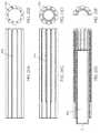
上述したように、これらの装置のいずれも、柔軟性チューブ(例えば、拡張可能な遠位端領域)がカテーテル上に解放可能に保持されるように構成することができる。例えば、これらの装置のいずれかは、柔軟性チューブをカテーテルに対して解放可能に保持するように構成された、柔軟性チューブの遠位端領域の周りの保持リングを具えることができる。 As mentioned above, any of these devices can be configured such that the flexible tube (eg, the expandable distal end region) is held releasably on the catheter. For example, any of these devices can include a retaining ring around the distal end region of the flexible tube configured to hold the flexible tube releasably with respect to the catheter.
これらの変形のいずれにおいても、柔軟性チューブは、カテーテル内に近位に引っ張られた後にカテーテル内にあるときに、異なる直径を有するように形状設定されてもよい。一般に、柔軟性チューブは、複数の織られたフィラメントか1つ(またはそれ以上)の編まれたフィラメントを含むことができる。いくつかの変形例では、柔軟性チューブの全体(または大部分)が織られたか編まれたフィラメントから形成され、柔軟性チューブの近位端は、プルワイヤを形成するフィラメントまたはフィラメントの束から反対側の先細の開口部を構成してもよい。代替的または付加的に、柔軟性チューブは、0.020インチ未満の厚さを有するポリマーのスリーブから形成することができ、このスリーブは、穿孔がポリマーを貫通する延びる穿孔パターンを有する。穿孔パターンは、円形穴、矩形穴およびジグザグ形状のうちの1つ以上からなる形状を有する穿孔を含むことができる。 In any of these variants, the flexible tube may be shaped to have a different diameter when in the catheter after being pulled proximally into the catheter. In general, the flexible tube can include multiple woven filaments or one (or more) woven filaments. In some variants, the entire (or most) flexible tube is formed from woven or woven filaments, with the proximal end of the flexible tube opposite the filament or bundle of filaments forming the pullwire. May form a tapered opening of. Alternatively or additionally, the flexible tube can be formed from a polymer sleeve having a thickness of less than 0.020 inches, which sleeve has a perforation pattern in which the perforations extend through the polymer. The perforation pattern can include perforations having a shape consisting of one or more of circular holes, rectangular holes and zigzag shapes.
これらの装置のいずれも、柔軟性チューブの近位端の一方の側に連結され、近位方向に引っ張られるとカテーテル内で柔軟性チューブを引っ張るように構成されたプルワイヤを含むことができる。 Any of these devices can include a pull wire that is coupled to one side of the proximal end of the flexible tube and is configured to pull the flexible tube within the catheter when pulled proximally.
一般に、柔軟性チューブは、任意の適切な長さであってもよい。例えば、柔軟性チューブは、3〜200cm(例えば、3〜150cm、3〜100cm、3〜50cmなど)であってもよい。 In general, the flexible tube may be of any suitable length. For example, the flexible tube may be 3 to 200 cm (eg, 3 to 150 cm, 3 to 100 cm, 3 to 50 cm, etc.).
本書記載の装置のいずれかにおいて、装置の柔軟性チューブは、柔軟性チューブの遠位端に所定量未満の力(例えば、500グラムの力、450グラムの力、400グラムの力、350グラムの力、300グラムの力、250グラムの力、200グラムの力、150グラムの力など)を加えると柔軟性チューブがカテーテル内に引き込まれるように構成されてもよい。 In any of the devices described in this document, the flexible tube of the device has less than a predetermined amount of force (eg, 500 grams of force, 450 grams of force, 400 grams of force, 350 grams of force) at the distal end of the flexible tube Forces, 300 grams of force, 250 grams of force, 200 grams of force, 150 grams of force, etc.) may be configured to pull the flexible tube into the catheter.
これらの変形のいずれにおいても、柔軟性チューブは、柔軟性チューブの第1の端部と第2の端部との間にテーパ部を含むことができる。いくつかの変形例では、柔軟性チューブはカテーテルの全長内で延在し、前記柔軟性チューブの近位端が前記カテーテルの近位端から近位側に離れるように引っ張られて前記柔軟性チューブを前記遠位端開口上で摺動し反転させるように構成される。 In any of these modifications, the flexible tube can include a taper between the first and second ends of the flexible tube. In some variants, the flexible tube extends within the entire length of the catheter and is pulled away from the proximal end of the catheter so that the proximal end of the flexible tube is proximal to the flexible tube. Is configured to slide and flip over the distal end opening.
本書記載の装置のいずれも、真空源を含むことができる。例えば、これらの装置のいずれも、ガイドワイヤ管腔の近位端に結合され、そこを通して真空を適用するように構成されたガイドワイヤ真空ポンプを含むことができる。例えば、これらの装置のいずれかは、前記カテーテルと前記柔軟性チューブとの間の空間に連結され前記カテーテルの内壁と前記柔軟性チューブとの間で前記カテーテルの管腔内に真空を適用するように構成された外側カテーテル真空ポンプを具えてもよい。 Any of the devices described in this document can include a vacuum source. For example, any of these devices can include a guidewire vacuum pump that is coupled to the proximal end of the guidewire lumen and configured to apply vacuum through it. For example, one of these devices is coupled to the space between the catheter and the flexible tube to apply a vacuum into the lumen of the catheter between the inner wall of the catheter and the flexible tube. It may be equipped with an outer catheter vacuum pump configured in.
上述のように、装置はプラーを具え、柔軟性チューブの遠位端はプラーの遠位端に連結されてもよい。外側カテーテルは、柔軟性チューブの近位端の近くのカテーテルの上に配置されてもよい。これらの装置のいずれも、外側カテーテルを前進させて柔軟性チューブの近位端を遠位方向に押すのと、プラーを近位方向に引っ張って柔軟性チューブの近位端をカテーテル内に引き込むのを調和させるように構成された制御を有するハンドルを具えてもよい。例えば、本明細書に記載される装置は、プラーであって、前記柔軟性チューブの遠位端が当該プラーの遠位端に連結されるプラーと、前記カテーテルの上に摺動可能に配置され前記柔軟性チューブの近位端に連結された外側カテーテルと、前記プラーを近位方向に引っ張って前記カテーテル内に柔軟性チューブの近位端を引き込みながら、前記外側カテーテルを遠位方向に前進させて前記柔軟性チューブの近位端を遠位方向に押すか、あるいは、前記外部カテーテルを近位方向に引っ張って前記柔軟性チューブの近位端を近位方向に引っ張りながら、前記プラーを遠位方向に押して前記柔軟性チューブの近位端を前記カテーテルの外に押し出すのを調和させるように構成された制御を有するハンドルとを具えてもよい。 As mentioned above, the device may comprise a puller and the distal end of the flexible tube may be connected to the distal end of the puller. The lateral catheter may be placed on top of the catheter near the proximal end of the flexible tube. In each of these devices, the lateral catheter is advanced to push the proximal end of the flexible tube distally, and the puller is pulled proximally to pull the proximal end of the flexible tube into the catheter. May be equipped with a handle having controls configured to harmonize. For example, the device described herein is a puller that is slidably disposed on a puller with the distal end of the flexible tube connected to the distal end of the puller and the catheter. The lateral catheter connected to the proximal end of the flexible tube and the puller are pulled proximally to pull the proximal end of the flexible tube into the catheter while advancing the lateral catheter distally. Pushing the proximal end of the flexible tube distally, or pulling the external catheter proximally to pull the proximal end of the flexible tube proximally while pulling the puller distally. It may be equipped with a handle having a control configured to harmonize the proximal end of the flexible tube with a directional push out of the catheter.
本明細書にはさらに、血栓を機械的に除去する方法であって、少なくとも血管内の凝血塊の近位端部までガイドワイヤを前進させるステップと、前記ガイドワイヤ上に血栓摘出(すなわち凝血塊除去)装置を遠位方向に前進させるステップであって、前記血栓摘出装置は、遠位端および遠位端開口を有するカテーテルと、前記カテーテルの外径に沿って前記カテーテルの遠位端部を越えて延在する柔軟性チューブとを具え、前記ガイドワイヤは前記カテーテルの管腔および前記柔軟性チューブを通っている、ステップと、前記柔軟性チューブを前記カテーテルの外径から離れてカテーテルの管腔内へと近位側に引っ張って、前記柔軟性チューブが前記遠位端開口上で摺動して反転するようにするステップと、前記柔軟性チューブが前記カテーテル内に引き込まれるのに伴い、前記反転された柔軟性チューブに凝血塊を引き込むステップとを含むことを特徴とする方法を記載する。 Further herein, a method of mechanically removing a thrombus, the step of advancing the guidewire to at least the proximal end of the clot in the blood vessel, and the removal of the thrombus on the guidewire (ie, the clot). Removal) A step of advancing the device in the distal direction, wherein the thrombectomy device provides a catheter with distal and distal end openings and the distal end of the catheter along the outer diameter of the catheter. With a flexible tube extending beyond, the guide wire passes through the lumen of the catheter and the flexible tube, a step and a tube of the catheter that separates the flexible tube from the outer diameter of the catheter. As the flexible tube is pulled proximally into the cavity so that the flexible tube slides over the distal end opening and flips over, and the flexible tube is pulled into the catheter. A method comprising the step of drawing a thrombus into the inverted flexible tube is described.
血栓を機械的に除去する方法は、血管内の凝血塊の近くにガイドワイヤを前進させるステップと、前記ガイドワイヤ上に血栓摘出装置を遠位方向に前進させるステップであって、前記血栓摘出装置は、遠位端および遠位端開口を有するカテーテルと、前記カテーテルの外径に沿って前記カテーテルの遠位端部を越えて延在する柔軟性チューブとを具え、前記ガイドワイヤは前記カテーテルの管腔および前記柔軟性チューブを通っている、ステップと、前記柔軟性チューブを前記カテーテルの外径から離れて前記遠位端開口の丸いリップを越えてカテーテルの管腔内へと近位側に引っ張って、前記柔軟性チューブが前記遠位端開口上で摺動して反転するようにするステップであって、前記遠位端開口は前記遠位端に直近の領域のデュロメーターより大きなデュロメーターを有するステップと、前記柔軟性チューブが前記カテーテル内に引き込まれるのに伴い、前記反転された柔軟性チューブに凝血塊を引き込むステップとを含むことを特徴とする。 The method of mechanically removing the thrombus is a step of advancing the guide wire near the blood clot in the blood vessel and a step of advancing the thrombus removing device distally on the guide wire, and the thrombus removing device. Includes a catheter with distal end and distal end openings and a flexible tube extending along the outer diameter of the catheter beyond the distal end of the catheter, the guide wire of the catheter. Steps through the lumen and the flexible tube and proximally to the flexible tube away from the outer diameter of the catheter and beyond the round lip of the distal end opening into the catheter lumen. The step of pulling so that the flexible tube slides and flips over the distal end opening, the distal end opening having a larger durometer than the durometer in the region closest to the distal end. It comprises a step and a step of pulling a thrombus into the inverted flexible tube as the flexible tube is pulled into the catheter.
血栓を機械的に除去する方法は、血管内の凝血塊の近くにガイドワイヤを前進させるステップと、前記ガイドワイヤ上に血栓摘出装置を遠位方向に前進させるステップであって、前記血栓摘出装置は、遠位端および遠位端開口を有する内側カテーテルと、前記カテーテルの外径に沿って前記カテーテルの遠位端部を越えて延在する柔軟性チューブと、前記柔軟性チューブの遠位端領域を前記内側カテーテルの外径に対して固定する外側カテーテルとを具え、前記ガイドワイヤは前記カテーテルの管腔および前記柔軟性チューブを通っている、ステップと、前記柔軟性チューブを前記カテーテルの外径から離れてカテーテルの管腔内へと近位側に引っ張って、前記柔軟性チューブの非潤滑性の遠位部分が前記内側カテーテルに引き込まれるまで前記柔軟性チューブの潤滑性の近位先端領域が前記遠位端開口上で摺動して反転するようにするステップと、前記柔軟性チューブが前記カテーテル内に引き込まれるのに伴い、前記反転された柔軟性チューブに凝血塊を引き込むステップとを含むことを特徴とする。 The method of mechanically removing the blood clot is a step of advancing the guide wire near the blood clot in the blood vessel and a step of advancing the thrombectomy device distally on the guide wire. A medial catheter with distal and distal end openings, a flexible tube extending along the outer diameter of the catheter beyond the distal end of the catheter, and a distal end of the flexible tube. With an outer catheter that secures the region to the outer diameter of the inner catheter, the guide wire passes through the lumen of the catheter and the flexible tube, a step and the flexible tube outside the catheter. The lubricious proximal tip region of the flexible tube is pulled away from the diameter and proximally into the lumen of the catheter until the non-lubricating distal portion of the flexible tube is pulled into the medial catheter. A step of sliding over the distal end opening to invert and a step of drawing a clot into the inverted flexible tube as the flexible tube is drawn into the catheter. It is characterized by including.
血栓を機械的に除去する方法は、血管内の凝血塊の近くにガイドワイヤを前進させるステップと、前記ガイドワイヤ上に血栓摘出装置を遠位方向に前進させるステップであって、前記血栓摘出装置は、遠位端および遠位端開口を有するカテーテルと、前記カテーテルの外径に沿って前記カテーテルの遠位端部を越えて延在する柔軟性チューブとを具え、前記ガイドワイヤは前記カテーテルの管腔および前記柔軟性チューブを通っている、ステップと、前記柔軟性チューブを前記カテーテルの外径から離れてカテーテルの管腔内へと近位側に引っ張って、前記柔軟性チューブが前記遠位端開口上で摺動して反転するようにするステップと、前記柔軟性チューブを押すか引いて前記カテーテルの遠位端部から出し、前記柔軟性チューブが前記遠位端開口上と前記カテーテルの外径上で摺動して反転するようにするステップと、前記柔軟性チューブが前記カテーテル内に引き込まれるのに伴い、前記反転された柔軟性チューブに凝血塊を引き込むステップとを含むことを特徴とする。 The method of mechanically removing the thrombus is a step of advancing the guide wire near the blood clot in the blood vessel and a step of advancing the thrombus removing device distally on the guide wire, and the thrombus removing device. Includes a catheter with distal ends and distal end openings and a flexible tube extending along the outer diameter of the catheter beyond the distal end of the catheter, the guide wire of the catheter. The step and the flexible tube passing through the lumen and the flexible tube are pulled proximally into the catheter's lumen away from the outer diameter of the catheter so that the flexible tube is distal. The step of sliding and flipping over the end opening and pushing or pulling the flexible tube out of the distal end of the catheter, the flexible tube over the distal end opening and of the catheter. It comprises a step of sliding on the outer diameter to invert and a step of drawing a clot into the inverted flexible tube as the flexible tube is drawn into the catheter. And.
本書記載の方法のいずれかにおいて、ガイドワイヤは、血管内の凝血塊内に少なくとも部分的に配置され得る。 In any of the methods described herein, the guide wire can be placed at least partially within a clot in a blood vessel.
本発明の新規な特徴は、以下の特許請求の範囲に詳細に記載されている。本発明の特徴および利点のより良い理解は、本発明の原理が利用される例示的な実施形態を説明する以下の詳細な説明および添付の図面を参照することによって得られるであろう。
本書は一般に、身体から物体を機械的に除去するための方法および装置が記載されている。これらの方法および装置は、様々な物体を身体の様々な領域から除去するために使用できるが、血管の管腔内から凝血塊を除去するのに特に適している。このように、本書には、機械的な血栓摘出装置(例えば、デバイスおよびシステム)が記載されている。 This book generally describes methods and devices for mechanically removing objects from the body. Although these methods and devices can be used to remove various objects from different areas of the body, they are particularly suitable for removing clots from within the lumen of blood vessels. As such, this document describes mechanical thrombectomy devices (eg, devices and systems).
本書記載の装置(例えば、血管から凝血塊を除去するための機械的血栓摘出装置)は、遠位端および遠位端開口を有する細長いカテーテルと、少なくとも部分的にカテーテル内にある柔軟性のトラクタアセンブリとを含むアセンブリであり、トラクタアセンブリの遠位端領域は、カテーテル内に少なくとも部分的に延び、カテーテルの遠位端部で二重に捲り返された遠位トラクタ領域として構成されている。トラクタアセンブリは、遠位トラクタ領域に接続された近接プッシャ領域を含むことができる。柔軟性トラクタアセンブリは、ガイドワイヤを通せるように構成された細長い管腔を含む。柔軟性トラクタアセンブリはまた、近位端領域が近位に引っ張られたときに、カテーテル管腔内の長軸に沿って摺動し、カテーテルの遠位端開口上で反転するように構成される。トラクタアセンブリは、本書では、柔軟性トラクタアセンブリ、柔軟性トラクタ部分、柔軟性トラクタチューブ、または単に柔軟性チューブと呼ばれ、典型的にカテーテル内に配置され長手方向に摺動可能であり、その遠位端領域(「遠位トラクタ領域」)がカテーテルの遠位端上で折り返されるよう構成される。 The devices described herein (eg, mechanical thrombectomy devices for removing clots from blood vessels) are elongated catheters with distal and distal end openings and flexible tractors that are at least partially within the catheter. An assembly that includes an assembly, the distal end region of the tractor assembly is configured as a distal tractor region that extends at least partially into the catheter and is doubly rolled up at the distal end of the catheter. The tractor assembly can include a proximity pusher region connected to the distal tractor region. The flexible tractor assembly includes an elongated lumen configured to allow guide wires to pass through. The flexible tractor assembly is also configured to slide along the long axis within the catheter lumen and flip over the distal end opening of the catheter when the proximal end region is pulled proximally. .. Tractor assemblies are referred to herein as flexible tractor assemblies, flexible tractor portions, flexible tractor tubes, or simply flexible tubes, which are typically located within the catheter and are longitudinally slidable and far away. The distal region (“distal tractor region”) is configured to fold over the distal end of the catheter.
例えば、図1Aは、本書記載の装置の一部を形成し得るカテーテルの1つの変形例を示す。本例では、カテーテル100は、遠位端105を含む遠位端領域103を具える。この遠位端領域は柔軟度が高いが(デュロメーターで測定、例えばショアデュロメーター)、最も遠位の先端(遠位端105)は、その直近の領域よりも実質的に柔らかくなくてもよい。したがって、遠位先端領域(例えば最も遠位の線形寸法x、ここでxは10cm、7cm、5cm、4cm、3cm、2cm、1cm、9mm、8mm、7mm、6mm、5mm、4mm、3mm)は柔軟度が高く/近位端から遠位端へと硬度が低くなるが、最も遠位の端部領域107(例えば最も遠位の線形寸法zとして測定、ここでzは1cm、9mm、8mm、7mm、6mm、5mm、4mm、3mm、2mm、1mm、0.8mm、0.5mm、0.3mm、0.2mm等であり、zは常にxの少なくとも1/3以下)はそのすぐ近位の領域より硬度が高く、それは遠位先端領域の最も近位の領域と同じ硬度かより硬くてもよい。 For example, FIG. 1A shows one variant of a catheter that may form part of the device described herein. In this example, the
カテーテル100は、内側カテーテルまたはトラクタカテーテルとも呼ばれる。神経血管への使用に適切なマイクロカテーテルを含む、任意の適切なタイプのカテーテルを用いることができる。
いくつかの変形例では、カテーテルの遠位端105は、遠位トラクタ領域が拘束(結束)または実質的な摩擦なしに、カテーテルの遠位端上を摺動し反転するように適合される。例えば、いくつかの変形例では、遠位先端(端部)は、図1Bに示すように、特に外側面(例えば、外径から内径への移行部)において、湾曲し丸みを帯びてもよい(109)。いくつかの変形例では、遠位先端は、図25A〜28に図示し説明されているように、1またはそれ以上のチャネルを含んでもよく、これには遠位トラクタ領域の摺動を案内するための、遠位方向に向いている縁の周りのチャネルが含まれる。 In some variants, the
図1Cは、柔軟性トラクタチューブ140の一例を示す。図1Cに示すように、チューブは柔軟性で細長く(カテーテル101よりも一般的に長い)、直近の領域146上に折り返されるように構成された最も遠位の拡張可能な第1端部領域144を有する遠位トラクタ領域142を具え、ここで領域146はあまり拡張しない第2の端部領域となる。一般に、拡張可能な遠位端領域は、拘束されていないときのカテーテル内径の直径の1.3〜10倍の半径方向の直径に拡張するように構成される。図1Dは、図1Cの拡張可能な遠位端領域の拡大構成を示す。このように、拡張可能な遠位端領域は、バイアスをかけて拡開することができる。この拡張可能な遠位端領域は、メッシュ、織物またはシートの材料として形成することができ、一般に、除去すべき物体(例えば、血栓)を掴むように適合される。 FIG. 1C shows an example of a
図1Cに一般的に示されている柔軟性トラクタチューブは、図1Eでは、拡張可能な遠位端領域が、自身の上に(すなわちより近位の、あまり拡張しない第2の端部領域上に)折り返されている。図1Eでは、拡張可能な遠位端領域が潰されているが、図1Fでは、拡張可能な遠位端領域が拡張されている。一般に、拡張可能な遠位端領域は、近位のあまり拡張しない第2の端部領域とは区別されるが、いくつかの変形例では、柔軟性トラクタチューブ全体は、カテーテル内で押し引きされる拡張可能な材料(例えば、メッシュ、織物など)でなり、近位のあまり拡張しない遠位端領域を含まないでもよい。 The flexible tractor tube, commonly shown in FIG. 1C, shows that in FIG. 1E, the expandable distal end region is above itself (ie, more proximal, on the less dilated second end region). It is folded back. In FIG. 1E, the expandable distal end region is collapsed, whereas in FIG. 1F, the expandable distal end region is expanded. Generally, the expandable distal end region is distinguished from the proximal, less dilated second end region, but in some variants the entire flexible tractor tube is pushed and pulled within the catheter. It consists of an expandable material (eg, mesh, woven fabric, etc.) and may not include a proximal, less dilated distal end region.
図1G、1Hは、図1A、1Eの構成要素から組み立てられた装置のような装置を使用した凝血塊の除去を示す。この例では、装置は、カテーテル101と、当該カテーテルの遠位端領域上に延在してカテーテルの遠位端上で2重に折り返されている拡張可能な遠位端領域144を有する柔軟性トラクタチューブとを具える血栓摘出装置として構成され、これにより拡張可能な遠位端領域は、カテーテル内で近位方向に延びてガイドワイヤを通す内部管腔を形成する内側かつ近位のあまり拡張しない(本例では、まったく拡張しないものもあまり拡張しないに含まれる)第2の遠位端領域146と連続している。柔軟性トラクタチューブの近位端(図示せず)は、遠位端領域(遠位トラクタ領域140)と連続しているロッドまたは他の部材であるプッシャー/プラー部材を含んでもよい。図1Gにおいて、装置は、凝血塊155近くの血管160内に配置され展開されて示されている。矢印180で示されるように、遠位トラクタ領域140をカテーテル101に引き込むことによって凝血塊がカテーテルに引き込まれ、これは、(例えばハンドルを使用して)柔軟性トラクタチューブの内側部分を引っ張ると、拡張可能な遠位端部領域がカテーテルの遠位端部内へと引っ張られ、拡張可能な遠位端部領域が反転し、これによって矢印182に示すようにカテーテル内に引き込まれる。拡張可能な遠位端領域の遠位端部は、カテーテルの外壁に対して「緩く(ルーズで)」あってもよいし、取り外し可能に取り付けられてもよいし、あるいはいくつかの変形例では恒久的に取り付けられてもよい。 1G and 1H show the removal of blood clots using a device such as a device assembled from the components of FIGS. 1A and 1E. In this example, the device is flexible with a
一般に、これらの装置の位置決めと操作は、これらが作動前および作動中の両方において非常に柔軟である必要があるため困難であり得る。例えば、一般に、柔軟性トラクタチューブはカテーテルの、特にカテーテルの遠位端領域の剛性/柔軟性をあまり大きくしてはならず、そうでないと特に神経血管の拷問的な血管内では操作が難しく、および/または危険になる。本書では、カテーテルの最後のycm(例えば、最も遠位の20cm、18cm、15cm、12cm、10cm、9cm、8cm、7cm、6cm、5cm、4cm、3cm、2cm、1cm、等)の剛性の増加が、所定のパーセンテージ以下(例えば、10%未満、12%未満、15%未満、18%未満、20%未満、25%未満、30%未満、等。)である柔軟性トラクタチューブ部分が記載されている。ここでは例えば、カテーテルを通ってカテーテルの遠位端で二重に折り返される柔軟性トラクタチューブ部分によるカテーテルの遠位5cmの剛性の増加は、カテーテルを通って延在しその遠位端部で二重に折り返される柔軟性チューブがない場合のカテーテルの遠位5cmの剛性の15%以下である。 In general, the positioning and operation of these devices can be difficult because they need to be very flexible both before and during operation. For example, in general, flexible tractor tubes should not increase the stiffness / flexibility of the catheter, especially in the distal end region of the catheter, or it is difficult to operate, especially within the torture vessels of neurovascular. And / or become dangerous. In this book, the increase in stiffness of the last ycm of the catheter (eg, the most distal 20 cm, 18 cm, 15 cm, 12 cm, 10 cm, 9 cm, 8 cm, 7 cm, 6 cm, 5 cm, 4 cm, 3 cm, 2 cm, 1 cm, etc.) , A flexible tractor tube portion that is less than or equal to a given percentage (eg, less than 10%, less than 12%, less than 15%, less than 18%, less than 20%, less than 25%, less than 30%, etc.). There is. Here, for example, the increase in stiffness of the catheter distal 5 cm due to the flexible tractor tube portion that is doubly folded back at the distal end of the catheter through the catheter extends through the catheter and is two at its distal end. Less than 15% of the stiffness 5 cm distal to the catheter in the absence of a heavily folded flexible tube.
例えば、図2Aは、柔軟性トラクタチューブ201を示す。本例では、柔軟性トラクタチューブは、拡張可能な第1の端部領域244と、近位のプッシャ領域201の遠位にあるあまり拡張しない第2の端部領域246とを有する遠位トラクタ領域242を具える。柔軟性トラクタチューブは全体が中空であり、ガイドワイヤ(図示せず)を通すことができる。柔軟性トラクタチューブの様々な領域は、同じ材料(例えば、織られた、編組されたフィラメント)から作製されてもよいし、異なる材料で作製されてもよい。 For example, FIG. 2A shows a flexible tractor tube 201. In this example, the flexible tractor tube is a distal tractor region having an expandable
図2Bは、遠位トラクタ領域、または複数の織られた繊維で形成された少なくとも拡張可能な第1の端部領域244’を有する柔軟なトラクタチューブを示す。代替的に、拡張可能な第1の端部領域は、1つ(またはそれ以上)の編まれた繊維、または織られた繊維と編まれた繊維の組み合わせで形成されてもよい。拡張可能な第1の端部領域は、繊維または織編パターンの形状設定特性によって、あるいは少なくとも拡張可能な第1の端部領域の遠位端領域を開かせる1またはそれ以上の付勢部材(例えば、リング、バネ、バンド、フィラメントなど)を含めることによって、(図示するように)開くようにバイアスされる。 FIG. 2B shows a flexible tractor tube having a distal tractor region, or at least an expandable first end region 244'formed of a plurality of woven fibers. Alternatively, the expandable first end region may be formed of one (or more) woven fibers, or a combination of woven and woven fibers. The expandable first end region is one or more urging members that open the distal end region of at least the expandable first end region by the shaping characteristics of the fiber or woven pattern. By including rings, springs, bands, filaments, etc.), they are biased to open (as shown).
図2Cは、複数の開口(例えば、孔、穿孔、通路、窓など)を有するシート材料から形成された拡張可能な第1の端部領域の別の変形例を示す。これらの開口は不均一なサイズ(例えば、サイズの範囲)または均一なサイズを含む、任意のサイズであり得る。シートを通るこれらの開口のサイズは、例えばポリマー材料(PTFE)、シリコーン材料、ポリウレタン、形状記憶合金など使用される材料に依存する。いくつかのバリエーションでは、シートの60%より大きい(70%超、75%超、80%超、85%超など、60〜95,65〜95,70〜95%など)気孔率を有することが有益でありうる。 FIG. 2C shows another variant of the expandable first end region formed from a sheet material with multiple openings (eg, holes, perforations, passages, windows, etc.). These openings can be of any size, including non-uniform size (eg, size range) or uniform size. The size of these openings through the sheet depends on the material used, for example polymer material (PTFE), silicone material, polyurethane, shape memory alloy. In some variations, it may have a porosity greater than 60% of the sheet (more than 70%, more than 75%, more than 80%, more than 85%, 60-95, 65-95, 70-95%, etc.). Can be beneficial.
これらの変形例のいずれにおいても、遠位トラクタ領域は、図2Dに示すように、それ自体反転可能(例えば、折り重ねられる)に構成されている。いくつかの変形例では、拡張可能な第1の端部領域が、それ自体の上および/またはカテーテルの遠位端領域の上で反転されるように実施され、または、生体内(例えば、血管内)でカテーテルの遠位端上に展開および反転され得るように構成される。一般に、装置を作動させることができる前に、カテーテルは、柔軟性トラクタチューブの拡張可能な第1の端部領域と、当該拡張可能な第1の端部領域に近接する領域、いくつかの変形例ではあまり拡張しない第2の遠位端領域、との間に挿入される。この空間289は、拡張可能な第1の端部領域の遠位端部またはその近傍の付勢部材によって開放状態に保持されてもよい。上述のように、この拡張可能な第1の端部領域の付勢部材は、リング、バンド、バネ、コイルなどであってもよく、付勢要素(例えば、形状記憶合金のような形状設定材料)、ゴムまたは他のポリマー材料などで作成されていてもよい。 In any of these variants, the distal tractor region is itself configured to be reversible (eg, folded), as shown in FIG. 2D. In some variants, the expandable first end region is implemented to be inverted over itself and / or the distal end region of the catheter, or in vivo (eg, a blood vessel). (Inside) is configured to be able to be deployed and flipped over the distal end of the catheter. Generally, before the device can be actuated, the catheter has an expandable first end region of the flexible tractor tube and an region close to the expandable first end region, some modifications. It is inserted between the second distal end region, which is less dilated in the example. This
本明細書で説明される装置のインビボ展開は、関連する課題にも拘わらず、装置を操作するユーザに多くの利点を提供することができる。図3A〜3Fは、インビボ展開用に構成された血栓摘出装置の一例を示す。本例では、装置は、ガイドワイヤ313を用いて(本書記載の変形例のいずれかと同様に)配置されるカテーテル301を具える。ガイドワイヤは、図3Aに血管360内の凝血塊355として示される除去対象物へと、またはその中に(あるいはそれを通して)延ばされる。装置のカテーテルは、ガイドワイヤと一緒にまたはその後に挿入され、柔軟性トラクタチューブがカテーテルの遠位端部またはその近くにあるか否かに拘わらず、凝血塊の近くに(近くに、または隣接して)配置することができる。図3Aでは、カテーテルは、ガイドワイヤが位置決めされた後に位置決めされ、図3Bに示すように、血管から取り出される。このガイドワイヤは、ワイヤ、小さなカテーテル、あるいは凝血塊および/またはそれを通して配置される(すなわち操縦される)器具の組み合わせであってもよい。カテーテルの位置決めに続いて、遠位トラクタ領域342を含む内側の柔軟性トラクタチューブ340が、図3Cに示すように、カテーテルを通して当該カテーテルの遠位端領域に押し進められる。この例では、遠位トラクタ領域を構成する柔軟性トラクタチューブの遠位端は、その近位端部に、柔軟性トラクタチューブの残りの部分と連続している近位のあまり拡張しない第2の端部領域に接続されたメッシュ344として示される拡張可能な第1端領域を具える(プッシャ領域305)。拡張可能な第1の端部領域の編組メッシュ344は、潰れた(拡張されていない)構成で管状の第2の端部領域/プッシャ領域の外側で事前に反転されており、カテーテルの内側管腔を通って、および(ガイドワイヤが所定位置に残っているかその近くで使用されたときに)ガイドワイヤ上で(図示せず)摺動可能である。次に、図3Dに示すように、柔軟性トラクタチューブの遠位トラクタ領域を延ばしてカテーテルの外側に露出させ(本例では柔軟性トラクタチューブを遠位方向に押すか、および/またはカテーテルを近位方向に引っ張って)、遠位トラクタ領域の拡張可能な第1の端部領域344(メッシュで示す)が第1の端部領域の長さに沿って拡張できるようにする。図3Dにおいて、これは、血管の内膜まで完全に拡張して、拡張可能な第1の領域と(本例では非拡張型の)第2の端部領域346との間の仕切りを形成するステント状構造として示されている。特に、第1の端部領域の拡張は、カテーテルの内側管腔の直径の1.3倍より大きくてもよい(例えば、1.5倍以上、2倍以上、2.2倍以上、2.5倍以上、3倍以上、3.5倍以上、4倍以上、5倍以上、6倍以上、7倍以上、8倍以上、9倍以上、10倍以上など)。 The in vivo deployment of the device described herein can provide many advantages to the user operating the device, despite the related challenges. 3A-3F show an example of a thrombectomy device configured for in vivo deployment. In this example, the device comprises a
図3Dでは、カテーテルは、遠位トラクタ領域の第1の端部領域と第2の端部領域との間で遠位方向にスライドされている。次に、柔軟性トラクタチューブ(例えば近位のプラー領域)を近位方向に引っ張ること、および/または、遠位方向にカテーテルを前進させることのいずれかまたは双方により、拡張可能な第1の端部領域を近位側にカテーテル内に引き戻すことによって、凝血塊を除去することができる。いくつかの変形例では、装置および特にカテーテルを前進させる一方で、拡張した第1の端部領域を引き戻してカテーテル内に反転させることが有益であり得る。柔軟性トラクタチューブが引き出されるよりも素早くカテーテルを進めることができる。 In FIG. 3D, the catheter is slid distally between the first end region and the second end region of the distal tractor region. The first end expandable by then pulling the flexible tractor tube (eg, the proximal puller region) proximally and / or advancing the catheter distally, or both. The clot can be removed by pulling the region region proximally back into the catheter. In some variations, it may be beneficial to pull back the dilated first end region and invert it into the catheter while advancing the device and especially the catheter. The catheter can be advanced faster than the flexible tractor tube can be pulled out.
図3Fに示すように、凝血塊355は、拡張可能な第1の端部領域を有するカテーテルに引き込まれる。 As shown in FIG. 3F, the
図4A〜4Fに、インビボでの展開方法および装置の別の変形例を示す。本例では、柔軟性トラクタチューブの自己拡張型の第1の端部領域が、カテーテルから押し出されると、カテーテルの遠位端部上を摺動してカテーテル端部を越えて自己拡張するように構成されている。図3A〜3Bについて説明したように、装置は、ガイドワイヤ413などを使用して配置することができる。図4Aにおいて、カテーテル401は、ガイドワイヤ413上で除去すべき凝血塊455の近くに配置される。図4Bに示すように、ガイドワイヤは、(任意に)除去されてもよいし、(好ましくは)その場所に残されてもよい。次いで、遠位トラクタ領域を含む柔軟性のトラクタチューブ434が、カテーテル内で遠位に移動され、拡張可能な第1の端部領域444と共に遠位端から延ばされ、それにより、図4Cに示すように、遠位端部上で反転し(466)、遠位端部上で摺動する。このプロセスは、血管内で装置を遠位方向に押すことによって、図4D〜4Eに示すように、第1の端部領域444の拡張によって血管壁に対してそれが固定されるため促進される。一旦露出されると、柔軟性トラクタチューブ434を近位側に引っ張り、および/またはアセンブリ(または少なくともカテーテル)を遠位方向に進めることによって、拡張可能な第1の端部領域を装置内に引き戻すことができる。次いで、凝血塊455を装置内に引き込むことができる。 4A-4F show another modification of the in vivo deployment method and device. In this example, the self-expanding first end region of the flexible tractor tube slides over the distal end of the catheter and self-expands beyond the catheter end when extruded from the catheter. It is configured. As described with reference to FIGS. 3A-3B, the device can be arranged using
図5A〜図5Eは、機械的な血栓摘出装置を用いたインビボ展開および血栓摘出(凝血塊除去)方法の別の変形を示す。図5Aでは、カテーテル501および内部の柔軟性トラクタチューブ534を含む装置500が、(例えば、図示しないガイドワイヤを介して)凝血塊555の近くに進められる。この例では(本書記載のいずれかの方法に関連して)装置は、展開されていない遠位トラクタ領域を有する柔軟性トラクタ部材が、既に装置の遠位端領域の近くに遠位に配置される。図5Bに示すように、図5Aのカテーテル501内で潰れた構成の拡張可能な第1の端部領域544は、図5B〜5Cに示すように、カテーテルの遠位端から押し出され、内腔の壁に向かって拡張する。一旦押し出されて拡張すると、カテーテルおよびカテーテル内の柔軟性トラクタチューブの部分が、図5Dに示すように遠位に進められ、これによって拡張可能な第1の端部領域544が反転し、カテーテル501の遠位端領域の上に折り重なる。図5Eに示すように、装置は凝血塊555の近くに展開され、既に述べたように凝血塊を除去するように作動されるが、遠位トラクタ領域の拡張可能な第1の端部領域をカテーテル内に引っ張ると、反転して凝血塊がカテーテル内に引き込まれる。任意でカテーテルを同時に前進させてもよい。上述のインビボ展開方法は、カテーテルを拡張可能な第1の端部領域と柔軟性トラクタチューブのより近位の部分との間に半径方向に配置するために、体内への挿入のための装置を装填するために用いてもよいことに留意されたい。 5A-5E show another variant of the in vivo deployment and thrombectomy (coagulation removal) method using a mechanical thrombectomy device. In FIG. 5A, a
図6Aは、本例では編組された(例えば、織られた)またはニット材料に形成された柔軟性の第1の(遠位)端部領域644を有する柔軟性トラクタチューブ634を有する血栓摘出装置の別の変形例を示し、この柔軟性の第1の端部領域(トラクタ領域)はカテーテル601の遠位端上に反転されており、柔軟性トラクタチューブ634の近位端領域に取り付けられている。本書記載の装置のいずれかと同様に、柔軟性トラクタチューブのこの近位端領域は、カテーテル内で押し引き可能なハイポチューブ、カテーテル、あるいは積層ウィーブ、/メッシュ、または編組材料であり、その遠位端部が柔軟性トラクタ領域(すなわち遠位トラクタ領域)に取り付けられ、いくつかの変形例では拡張可能な第1の端部領域を具える。いくつかの変形例では、遠位トラクタ領域(第1の端部領域)は拡張可能でなく、ただ柔軟であってもよいことに留意されたい。 FIG. 6A is a thrombectomy device with a
図6Aに示すように、柔軟性トラクタチューブに取り付けられた遠位トラクタ領域の第1の端部領域は、外側カテーテルまたはスリーブ(プロテクタ)677によって覆われている。この例では、装置はまた、内側カテーテル601と保護カテーテルまたはスリーブ677との間の中間カテーテル679を具える。いくつかの変形例では、柔軟性の第1の端部領域644はこの中間カテーテルに取り付けられるが、それには脱着可能に取り付けられて、柔軟性トラクタチューブ634を近位に引っ張るとそれが外れ、メッシュ(柔軟性の第1の端部領域644)が血管内に展開する。図6Aに示す変形例では、柔軟性の第1の端部領域644は、中間カテーテル679に取り付けられていない。 As shown in FIG. 6A, the first end region of the distal tractor region attached to the flexible tractor tube is covered by an outer catheter or sleeve (protector) 677. In this example, the device also comprises an
図6Aに示す装置を含む本書記載の装置のいずれかは、図6Bに示すようにガイドワイヤ633とともに用いる(これを具える)ことができる。図7A〜7Dは、図6A〜6Bに示す装置の凝血塊755除去動作動作を示す。この装置では、柔軟性トラクタチューブ734の近位端を真空源(図示せず)に連結して、これをトラクタチューブ734を近位に引き戻して遠位トラクタ領域をカテーテル上で反転させるときに作動させることができる。図7Aにおいて、装置は凝血塊755の近くに配置される。図7Bでは、矢印で示すように、柔軟性トラクタチューブ734を引っ張ると、遠位トラクタ領域が反転され、カテーテル内に引き込まれる。本例では、遠位トラクタ領域は、図7B、7Cに示すように、外側スリーブ777に覆われたままであるため、拡張されない。この装置は、遠位トラクタ端部領域(本例ではメッシュ744として示す)を押すか近位に引っ張るかの一方または双方によって、凝血塊の方へ/越えて遠位方向に進められ、カテーテルの遠位端部上で反転させる。凝血塊が除去されると、装置は図7Dに示すように引き戻され、血管から引き出される。 Any of the devices described herein, including the device shown in FIG. 6A, can be used (equipped with) with the
上記のように、いずれの変形例も、1以上の真空源を含んでもよい。図8は、柔軟性トラクタチューブ834の管腔に連結された近位端に第1の任意の真空源を示す、真空源を具える一実施例を示す。例えば、真空とトラクタチューブ834との連結は、図示するように回転止血弁(RHV)であってもよい。図8では、(オプションの)外側カテーテル877と内側カテーテル801または(任意の)中間カテーテル878との間に、第2の(任意の)真空接続を設けてもよい。真空は、この方法の任意の適切な部分に適用することができ、これには凝血塊を除去するために柔軟性トラクタチューブ834を引っ張る最中が含まれる。 As mentioned above, any of the modifications may include one or more vacuum sources. FIG. 8 shows an embodiment with a vacuum source showing a first arbitrary vacuum source at the proximal end connected to the lumen of the
前述のように、本書記載の装置のいずれかは、ガイドワイヤを具え、処置中にガイドワイヤをその位置に留めてもよい。図9A〜9Dは、ガイドワイヤ913を定位置に残して物体(例えば、凝血塊)を除去する方法を示す。本例では、装置は図6A〜6Bに示す装置と同様であり、任意の真空源を具えてもよい。図9Aに示すように、遠位トラクタ領域944の柔軟性の第1の端部領域944の反転部分を含むカテーテルの遠位端が凝血塊の近くに配置され、近位方向に引っ張って作動されて、図9Bに示すように凝血塊がカテーテル内に引き込まれる。本例では、凝血塊はガイドワイヤ913に貫通されており、したがって反転したトラクタ領域を含むカテーテル先端部は、カテーテル927を押すことによって、および/またはトラクタチューブを近位919に引っ張ることによって、ガイドワイヤ上を前進される。図9Cに示すように凝固物全体がカテーテル内に入るまでこれが続けられる。 As mentioned above, any of the devices described herein may include a guide wire and hold the guide wire in place during the procedure. 9A-9D show a method of removing an object (eg, a clot) by leaving the
本書記載の変形例のいずれにおいても、装置は、1つ以上のマーカーを含むことができ、または1以上の造影剤とともに使用するように構成されて、記載された方法を視覚化するのを補助してもよい。さらに、これらの方法のいずれも視覚化を含んでもよい。視覚化は、間接的(例えば、蛍光透視法または同等技術を使用する)であってもよいし、例えば装置を直接視覚化するために(例えば、装置の内腔を通して)1本の光ファイバーを使用して行われてもよい。 In any of the variants described herein, the device can include one or more markers, or is configured to be used with one or more contrast agents to assist in visualizing the described method. You may. Moreover, any of these methods may include visualization. The visualization may be indirect (eg, using fluoroscopy or equivalent techniques) or, for example, using a single optical fiber to directly visualize the device (eg, through the lumen of the device). It may be done.
図9Dでは、捕捉された物体(例えば凝血塊)を有するトラクタチューブは、装置から近位方向に取り去られ、除去された材料は(例えば、組織学的/細胞学的検査によって)検査することができる。その後に、または同時にカテーテルを取り出す。上述のように、対象物(例えば凝血塊)を除去するとき、柔軟性トラクタチューブを近位に引き戻すのと同時にガイドワイヤを(近位に)引き戻すことが望ましい(図示せず)。いくつかの変形例では、遠位のトラクタ領域(例えば、編組/織物または編成領域)は、カテーテル内でガイドワイヤを掴み(grab)、図36、37A〜37Cでより詳細に説明するように、これがまた装置を遠位方向に/凝血塊に向かって推進するのを補助する。 In FIG. 9D, the tractor tube with the captured object (eg, clot) is removed proximally from the device and the removed material is examined (eg, by histological / cytological examination). Can be done. Subsequent or simultaneous removal of the catheter. As mentioned above, when removing an object (eg, a clot), it is desirable (not shown) to pull the flexible tractor tube back proximally and at the same time pull back the guide wire (proximal). In some variants, the distal tractor region (eg, braided / woven or braided region) grabs the guide wire within the catheter (grab), as described in more detail in FIGS. 36, 37A-37C. This also helps propel the device distally / towards the clot.
一般に、この掴み部(遠位トラクタ領域)の回転効果は、遠位トラクタ領域に対するカテーテルの動きによって作動される。遠位トラクタ領域が近位に固定され、カテーテルが前進する場合、遠位トラクタ領域は1:1の掴み比(grab ratio)を有する。遠位のトラクタ領域がカテーテルを通して引っ張られると、掴み効果は増幅される。例えば、内側カテーテルが1単位だけ遠位へ進められたときに、遠位のトラクタ領域が(トラクタチューブを引っ張ることによって)引き戻され反転してカテーテル内へ近位方向へ1ユニット入る場合は、掴み作用は約2倍となる。内側カテーテルが1単位だけ遠位に進められたときに、遠位トラクタ領域が内側カテーテル内に近位に2単位引き込まれる場合、掴み作用は約3倍となる。遠位トラクタ領域とカテーテルとの並行運動は、ハンドルによって調整することができる。 In general, the rotational effect of this grip (distal tractor region) is driven by the movement of the catheter relative to the distal tractor region. When the distal tractor region is fixed proximally and the catheter advances, the distal tractor region has a 1: 1 grab ratio. The gripping effect is amplified when the distal tractor area is pulled through the catheter. For example, if the medial catheter is advanced one unit distally and the distal tractor region is pulled back (by pulling on the tractor tube) and flipped into one unit proximally into the catheter, grab it. The action is about doubled. If the distal tractor region is retracted proximally into the medial catheter by 2 units when the medial catheter is advanced distally by 1 unit, the gripping action is approximately tripled. The parallel movement of the distal tractor area and the catheter can be adjusted by the handle.
一般に、本書記載の装置のいずれも、ハンドルを含むことができる。このハンドルは、柔軟性トラクタチューブおよび/またはカテーテル(例えば、内側カテーテル)および/または任意の外側カテーテル(例えば、プロテクタ、スリーブなど)と結合してもよい。ハンドルは、柔軟性のトラクタチューブおよび/またはカテーテルの選択的な個別の動作、および/またはこれらの構成要素の座標運動が可能に構成されてもよい。図10A、10Bは、使用され得るハンドルの例を示す。図10Aにおいて、ハンドルは、トラクタチューブを引き戻し、したがって遠位トラクタ領域をカテーテルの遠位端上で反転させ、および/または遠位トラクタ領域に対してカテーテルを前進させる駆動機構を具える。図10Aにおいて、ハンドルは、カテーテル駆動装置1003に連結された回転可能なハンドル1001を含む。このハンドルは、カテーテル1005と、遠位トラクタ領域1011を有する内側の柔軟性トラクタチューブ1009の両方に接続する。ハンドルは、トラクタチューブの(近位への)引き戻しに対するカテーテルの(遠位への)前進の比が、カテーテル駆動装置のねじ山のネジピッチまたは他の機械的機構により選択され、および/または依存してもよい。 In general, any of the devices described herein can include a handle. The handle may be coupled with a flexible tractor tube and / or catheter (eg, medial catheter) and / or any lateral catheter (eg, protector, sleeve, etc.). The handle may be configured to allow selective individual movement of the flexible tractor tube and / or catheter and / or coordinate movement of these components. 10A and 10B show examples of handles that can be used. In FIG. 10A, the handle comprises a drive mechanism that pulls back the tractor tube and thus flips the distal tractor region over the distal end of the catheter and / or advances the catheter relative to the distal tractor region. In FIG. 10A, the handle includes a
ハンドルの別の変形例が図10Bに示されている。この例では、ハンドルはトラクタチューブに取り付けられ、トラクタチューブを引っ張って(または押して)(1017)遠位のトラクタ領域をカテーテルの遠位端部上で反転させ、ハンドルの別の部分はカテーテルに連結されてカテーテル1015を押し引きする。 Another modification of the handle is shown in FIG. 10B. In this example, the handle is attached to the tractor tube and pulls (or pushes) the tractor tube (1017) to flip the distal tractor region over the distal end of the catheter and connect another part of the handle to the catheter. The
図11Aは、別のバリエーションのハンドル機構1107を示し、これは取り付け部位1105でトラクタチューブの近位端部に連結することによって、および/または、カテーテルの近位端部に連結することによってカテーテルを前進させることにより、本明細書に記載された装置のいずれかの掴み部(遠位トラクタ領域)を引っ張るように構成されている。ハンドル機構の別の実施例が図11Bに示されており、レバー機構1109と、固定式または調節式の内側トラクタチューブへの連結とが示されている。 FIG. 11A shows another variation of the
本書記載の装置(すなわち機械的血栓摘出装置)のいずれかにおいて、遠位トラクタ領域はカテーテル内/上に予め装填され、遠位トラクタ領域に連結されたトラクタルーブ(tractor rube)を近位に引っ張ることによって、および/またはカテーテルを遠位に前進させることによって作動させることができる。遠位トラクタ領域が、カテーテルの遠位端部上で二重にされた柔軟性および/または拡張可能な第1の端部領域(例えば、メッシュおよび/または織り材料から形成される)を有する予め装填された形態は、装置は、第1の端部領域が凝血塊またはその近くに配置される前に、当該第1の端部領域の不注意な脱落および/または拡張を防止するように適合されている。 In any of the devices described herein (ie, mechanical thrombotomy devices), the distal tractor region is preloaded in / on the catheter and pulls proximally to the tractor rube connected to the distal tractor region. This can be activated by and / or by advancing the catheter distally. The distal tractor region pre-exists with a doubled flexibility and / or expandable first end region (eg, formed from a mesh and / or woven material) on the distal end of the catheter. The loaded form is adapted so that the device prevents inadvertent shedding and / or expansion of the first end region before it is placed in or near the clot. Has been done.
図12A、12Bは、カテーテルの外側に取り付けられた遠位トラクタ領域用の解放可能なアタッチメントの実施例を示す。これらのアタッチメントは、柔軟性トラクタチューブの近位端に適用される適切な量の力(例えば、引っ張り力)の適用によって解放することができる。例えば図12Aでは、遠位トラクタ領域の外側遠位端(メッシュ1204として示す)は、外側カテーテルまたは管1203から延びるショルダー部またはソックス部に覆われている。同様に図12Bでは、遠位トラクタ領域の外側遠位端(メッシュ1204として示す)は、別個のバンド、リング、またはソックス部1209に覆われている。この遠位トラクタ領域は、フィラメント(例えば、編組または織りのバリエーション、さらなる編組フィラメント)を添加することによって、コーティングを付加することによって、より大きな直径に熱硬化させることによって、および/または軸方向の相互編組プルワイヤを追加することによって、(例えばトラクタチューブを近位に引っ張って)応力がかかった場合でも潰れないか、直径が減少しないようになっている。 12A, 12B show examples of releasable attachments for the distal tractor region attached to the outside of the catheter. These attachments can be released by applying an appropriate amount of force (eg, tensile force) applied to the proximal end of the flexible tractor tube. For example, in FIG. 12A, the lateral distal end of the distal tractor region (shown as mesh 1204) is covered by a shoulder or sock that extends from the lateral catheter or
本書に記載されたバリエーションのいずれも、柔軟性トラクタチューブの一部として、近位プルロッドまたはプルワイヤを含んでもよい。さらに、トラクタチューブの近位端領域は、遠位端(遠位トラクタ領域)よりも柔軟性が低くてもよい。図13A、13Bは、柔軟性トラクタチューブの実施例を示す。図13Aにおいて、このチューブは、プルワイヤ内へと近位方向にテーパした材料(例えばメッシュ/織物材料)1307から遠位トラクタ領域1305が形成され、ガイドワイヤ1309用の空間を残し、遠位トラクタ領域がカテーテル上で反転できるようにした近位テーパ領域を具える。近位プルワイヤ部分は、遠位トラクタ領域が織られまたは編まれたバリエーションにおいては、遠位トラクタ領域を形成するフィラメントから構成することができる。これらのフィラメントは、例えば、より硬くしたりより柔軟にするポリマーといった他の材料によって強化することができる。図13Bは、柔軟性トラクタチューブの近位端が、プルワイヤの遠位端に取り付けられた別個の材料または編組ワイヤ束の延長部であって遠位トラクタ領域1317を形成するプルワイヤ1315で形成された別の実施例を示す。 Any of the variations described herein may include a proximal pull rod or pull wire as part of the flexible tractor tube. In addition, the proximal end region of the tractor tube may be less flexible than the distal end (distal tractor region). 13A and 13B show examples of flexible tractor tubes. In FIG. 13A, the tube has a
本書記載の装置はいずれも、カテーテルの端部上で遠位トラクタ領域を反転させるのに必要な力を低減するように工夫または適合することができる。例えば、いくつかの変形例では、遠位端が潤滑性を有するように処理されてもよいし、遠位トラクタ領域の全部または一部が引っかからないように処理されてもよい。例えば、いくつかの変形例では、遠位トラクタ領域の一部のみ、例えば、カテーテルの遠位端を最初に相互作用/反転させる部分のみが処理され、遠位トラクタ領域の残りの部分は処理されないでもよい。図14は、このような装置の一例を示す。図14において、(カテーテルの外側に位置する)拡張可能および/または柔軟性の第1端部領域の近位端1405は、潤滑性コーティングで処理されるか、または潤滑性材料で形成される。第1の端部領域の残りの部分(同尺でない)1403は、同様に潤滑性ではない。より近位の領域1405が血管およびカテーテルの遠位端に晒されるので、目標をより効果的に追跡するだけでなく、より効果的に遠位端を反転開始することができる。この領域は、疎水性/親水性コーティングのようなコーティングを行ったり、より潤滑性のポリマー材料(例えば、PTFE)を形成あるいは含めることを含むが、これらに限定されない任意の適切な方法で潤滑性にすることができる。 Any of the devices described herein can be devised or adapted to reduce the force required to flip the distal tractor region over the end of the catheter. For example, in some variants, the distal end may be treated to be lubricious, or the distal tractor region may be treated so that all or part of it is not caught. For example, in some variants, only part of the distal tractor region, eg, the portion that first interacts / flips the distal end of the catheter, is treated and the rest of the distal tractor region is not treated. It may be. FIG. 14 shows an example of such a device. In FIG. 14, the
一般に、本書記載の遠位トラクタ領域はいずれも、遠位端部上を摺動/移動し、および/または、凝血塊または他の除去対象目標を掴むのに適した(例えば形状設定された)外形を有するように、プリセットされたものを含む異なる外形を具えるのに適合してもよい。例えば、図15A〜15Dは、異なる遠位トラクタ領域を形成する異なる遠位端プロファイルを有するトラクタチューブを示す。例えば、図15Aでは、遠位トラクタ領域は、複数のプルワイヤによってトラクタチューブの近位端に接続された編組/メッシュまたは織物材料で形成された最遠位の拡張可能および/または柔軟性の第1の端部領域1505を具える。これらのプルワイヤ1517は、編組/メッシュまたは織った遠位端領域を形成するのと同じワイヤまたはフィラメントによって形成することができる。図15Bは、複数の個別の編組/メッシュまたは織った遠位端領域がプルワイヤ1515によって接続されている別の変形例を示し、これらのプルワイヤ領域1515は、編組/メッシュまたは織物領域1516よりも拡張性および/または柔軟性が低くてもよい。図15Cでは、遠位端領域は、編組/メッシュまたは織物であるが、異なる直径を有するように予め設定されている。したがって、これらの領域は、その長さに沿って異なる形状を有し得る。これらの形状は、それらがカテーテル内に引っ張られる際に凝血塊をより良く掴むか壊すためにヒートセットすることができる。図15Dは、編組/メッシュまたは織物の遠位トラクタ領域1523を形成したのと同じフィラメントまたはフィラメント束によってトラクタチューブ1520のハイポチューブまたは他のより近位の端部領域に接続された編組またはステント状の第1の端部領域1521の実施例を示す。 In general, any of the distal tractor regions described herein are suitable (eg, shaped) for sliding / moving over the distal end and / or grabbing a clot or other target for removal. It may be adapted to have different contours, including presets, to have contours. For example, FIGS. 15A-15D show tractor tubes with different distal end profiles that form different distal tractor regions. For example, in FIG. 15A, the distal tractor region is the most distal expandable and / or flexible first formed of a braided / mesh or woven material connected to the proximal end of the tractor tube by multiple pull wires. The
いずれかの本書記載の装置はさらに、あるいは代替的に、遠位のトラクタ領域(および特に遠位端部分)を外面に固定する複数の解放可能なアタッチメントを、カテーテルの外面に具えてもよい。図16には、遠位トラクタ領域1644の遠位端をカテーテル1601の外側に固定する解放可能なアタッチメントを形成する3つのリング1603、163’、1603”が示されている。この例では、ポリマーコーティング/フィルムが、遠位トラクタ領域を形成する編組みに統合されており、(例えば、使用者が引っ張るまで)カテーテルからスライドまたは滑って出るのを防止する。この装置は、カテーテル送達システムの外径に固定された状態を維持するのを補助するための、図示のようにカテーテルの長さに沿って半径方向に配置された複数のアタッチメントを具える。いくつかの変形例では、これらの解放可能なアタッチメントは、弾性部材(例えば、ウレタンリング)であるが、壊れやすく、破断して遠位トラクタ領域を解放可能であってもよい。 Any of the devices described herein may further or optionally include a plurality of releasable attachments on the outer surface of the catheter that secure the distal tractor region (and especially the distal end portion) to the outer surface. FIG. 16 shows three
図17は、遠位トラクタ領域の一部がバネ装填(付勢)され、カテーテルの遠位端を越えてカテーテル管腔内に転がるようにそれを駆動するように、解放可能なアタッチメントが配置された別の変形例を示す。図17において、遠位トラクタ領域1704の遠位端は固定され(固定されるか、取り付けられるか、ルーズに拘束されている)、カテーテルの遠位端付近のより近位の端部領域をカテーテル1707に解放可能に固定することができる。例えばポリマーコーティングまたはフィルムが遠位トラクタ領域(図17では編組1744として示される)に取り付けられ、遠位トラクタ領域1705の一部を、遠位端1704と解放可能なアタッチメントの部位1707との間で緊張状態で保持するように(例えば、圧迫により)結合されている。次に、解放可能なアタッチメント1707を解放すると、遠位トラクタ領域をカテーテルの遠位端の周りに駆動する力が加えられ、これが凝血塊を装置内に引き込むのを助け、遠位トラクタ領域を反転させるのに必要な力が低減される。 In FIG. 17, a releasable attachment is placed so that a portion of the distal tractor region is spring loaded and drives it to roll over the distal end of the catheter into the catheter lumen. Another modification is shown. In FIG. 17, the distal end of the
上述のように、遠位トラクタ領域を形成する材料、特に最遠位の柔軟性および/または拡張可能な第1の端部領域は、任意の適切な材料で形成されてもよい。例えば、材料は、布地、織物、編物、編組、縫製、チューブ、および/または平らなシートを含んでもよい。材料は、任意の適切な厚さ、例えば0.0005〜0.015インチの壁厚を有し、低気孔率から高気孔率までの任意の適切な間隔/寸法(気孔率)の気孔を有してもよい。遠位トラクタ領域の全部または一部は、放射線不透過性あるいは放射線透過性であってもよい。織物、編物、編組または縫製されたバリエーションでは、材料は、マルチフィラメントまたはモノフィラメントで形成されてもよい。異なるサイズのフィラメントを一緒に混合して(例えば、大および/または小)、織物表面の質感を増減することによって把持効果を変えることができる。いくつかの変形例において、材料(当該材料を構成するフィラメントを含む)は、ポリマーベース(PET、ナイロン、ポリプロピレン、PTFE、ePTFE)、弾性及び非弾性材(例えば、PU、シリコーン、ゴム、ライクラ)、金属フィラメント(例えば、Niti、DFTを含むdrawn filled Niti、例えばPt内部コアを有するNiti、鋼、ステンレス鋼、コバルトクロム等)、および金属フィラメントとポリマーフィラメントの混合物であってもよい。織物の端部は、レーザー切断/溶接または自由切断であり得る。いくつかの変形例では、遠位トラクタ領域の全部または一部は、フィルムまたはシートを含む。フィルムの厚さは、0.0005〜0.008インチであってもよい。このフィルムは、チューブ押出、あるいはシートで形成されチューブに丸めてよい。いくつかの変形例では、フィルムは糸補強される。フィルムは、溝がついていてもよい(例えば、把持またはカテーテルへの滑りをよくするために穴および/またはスリットカットを含んでもよい)。いくつかの変形例では、フィルムはテクスチャ表面を有してもよい(反転したときにテクスチャされた内面が露出する)。フィルムは、長さ方向に隆起部および/またはリング(半径方向リング)および/またはラインを有するチューブを形成し、および/または鋸歯状パターンを形成してもよい。テクスチャされた内面は、大小フィラメントの混合を含み、および/またはより多孔性で低密度のファブリックを構成してもよい。 As mentioned above, the material forming the distal tractor region, in particular the most distal flexible and / or expandable first end region, may be formed of any suitable material. For example, the material may include fabrics, fabrics, knits, braids, sewing, tubes, and / or flat sheets. The material has a wall thickness of any suitable thickness, eg 0.0005 to 0.015 inch, and has pores of any suitable spacing / dimension (porosity) from low porosity to high porosity. You may. All or part of the distal tractor region may be radiopaque or radiopaque. In woven, knitted, braided or sewn variations, the material may be formed of multifilament or monofilament. Filaments of different sizes can be mixed together (eg, large and / or small) to vary the gripping effect by increasing or decreasing the texture of the fabric surface. In some variants, the material (including the filaments that make up the material) is a polymer base (PET, nylon, polypropylene, PTFE, ePTFE), elastic and inelastic materials (eg PU, silicone, rubber, lycra). , A metal filament (eg, Nyl, a drown field Niti containing DFT, such as Niti with a Pt internal core, steel, stainless steel, cobalt chrome, etc.), and a mixture of the metal filament and the polymer filament. The edges of the fabric can be laser cut / welded or free cut. In some variants, all or part of the distal tractor area comprises a film or sheet. The thickness of the film may be 0.0005 to 0.008 inches. The film may be extruded into a tube or formed of a sheet and rolled into a tube. In some variations, the film is thread reinforced. The film may be grooved (eg, may include holes and / or slit cuts for better gripping or sliding into the catheter). In some variants, the film may have a textured surface (the textured inner surface is exposed when flipped). The film may form a tube with ridges and / or rings (radial rings) and / or lines in the longitudinal direction, and / or form a serrated pattern. The textured inner surface may contain a mixture of large and small filaments and / or form a more porous, low density fabric.
いくつかの変形例では、掴み要素の視認性は望ましいものであるが、全体を通して要求されるものではない。例えば上述したように、マーカーを装置上に設けることができる。いくつかのバリエーションでは、構造全体、あるいは構造の近位端と遠位端を見ることが望ましい場合がある。例えば、可視性を高めるために、材料はNitinolまたはプラチナ上にNitinolを設けた材料(DFT)であってもよい。 In some variants, visibility of the gripping element is desirable, but not required throughout. For example, as described above, markers can be provided on the device. In some variations, it may be desirable to look at the entire structure, or the proximal and distal ends of the structure. For example, for increased visibility, the material may be Nitinol or a material (DFT) with Nitinol on platinum.
いずれの変形例も、凝血塊をハブに引き入れるのを補助するために、編組体のいずれかの内側に回転螺旋要素を含むことができる。上述のように、これらの装置のいずれも真空源を含むことができる。システムに真空装置を加えると、遠位トラクタ領域が凝血塊/塞栓をカテーテルに引き込む能力を向上することができる。適用される真空は、不変/一定、漸増(ramped)またはパルス状であってもよい。 Each variant may include a rotating spiral element inside any of the braids to assist in drawing the clot into the hub. As mentioned above, any of these devices can include a vacuum source. Adding a vacuum device to the system can improve the ability of the distal tractor region to pull the clot / embolus into the catheter. The applied vacuum may be invariant / constant, ramped or pulsed.
いくつかの変形例では、装置およびそれらを使用する方法は、処置中に凝血塊の圧力を下げる流れ止め近位バルーン(例えば、凝血塊の近位に配置される)を含んでもよい。 In some variants, the devices and methods using them may include a flow stop proximal balloon (eg, placed proximal to the clot) that reduces the pressure of the clot during the procedure.
本書記載の装置および方法は、生検試料を(例えば、乳房または他の任意の器官から)捕捉するために使用することができる。例えば、これらの装置は、腹腔鏡手術が行われるときに、より大きな組織部分(例えば、癌、胆嚢など)を除去するために使用することができる。 The devices and methods described herein can be used to capture biopsy samples (eg, from the breast or any other organ). For example, these devices can be used to remove larger tissue parts (eg, cancer, gallbladder, etc.) when laparoscopic surgery is performed.
遠位トラクタ領域を形成する材料が織物/編組材料である場合、得られるメッシュ構造は、カテーテルの外径(OD)より1〜100cm長い範囲の編組長さを有してもよく、好ましい長さは約3〜30cmの間である。 When the material forming the distal tractor region is a woven / braided material, the resulting mesh structure may have a braid length in the range of 1-100 cm longer than the outer diameter (OD) of the catheter, preferably a length. Is between about 3 and 30 cm.
これらの変形例のいずれにおいても、トラクタチューブおよび/またはカテーテル(遠位トラクタ領域を含む)は、遠位トラクタ領域を引っ張ると、遠位トラクタ領域が最小限の力でカテーテルの遠位端部の外径周りで引っ張られ(反転され)、したがってカテーテルの先端が血管内で座屈せず、または大きく変形(すなわち曲がる)しないように構成され、ここで引っ張る力は約50グラム、100グラム、300グラム、500グラム、800グラム、1000グラム、2kg、3kg、5kg、8kg、10kg、15kg、20kgなどより小さい。 In any of these variants, the tractor tube and / or catheter (including the distal tractor region) pulls on the distal tractor region and the distal tractor region exerts minimal force on the distal end of the catheter. It is constructed so that it is pulled (reversed) around the outer diameter and therefore the tip of the catheter does not buckle or deform (ie bend) significantly in the blood vessel, where the pulling force is about 50 grams, 100 grams, 300 grams. , 500 grams, 800 grams, 1000 grams, 2 kg, 3 kg, 5 kg, 8 kg, 10 kg, 15 kg, 20 kg and the like.
掴み部(遠位トラクタ領域)が、少なくとも遠位端(例えば、拡張可能および/または柔軟性の第1の端部領域)上の織物(例えば、編組)構造として構成される変形例では、織物構造を構成するフィラメントの例は、NiTi、NiTi−PT DFTワイヤ(Ptのインナー上にNiTiチューブ)、PET、PP、ナイロン、Algiloy、SS、ハイブリッド材料を含み得る。使用時に、NiTiをエッチングして非常に滑らかにすることができる。フィラメントの端部の数は、約16、24、36、48、77、96、144またはこれらの整数の間の任意の数であってもよい。様々な編組構造を利用することができる。例えば、例示的な編組構造は、1×1、1×2、2×2などを含む。いくつかの変形例では、織物材料および/または編物材料を構成するフィラメントはモノフィラメントを含み、例えば、外径(OD)サイズが約0.0005”、0.00075”、0.001”、0.0015”、0.002”、0.003”またはこれらの列挙された整数間のサイズまたは直径寸法の組み合わせである。上記のように、これらの装置は、例えば血管内径(ID)が2〜3mmの神経脈管構造に適合させることができる。例えば、本書記載の神経脈管の応用に適した装置は、36〜72端の、3〜7mmのODに焼きなましされた0.001”〜0.002”のポリマー編組を含むことができる。いくつかの変形例では、遠位トラクタ領域は、ODが0.0005”から0.0015”の24本の編組ワイヤか、あるいは2mmのマンドレル上で焼きなましされ45度の角度で編組された0.002”の平らなNitiワイヤを含む。あるいは、一変形例では、遠位トラクタ領域は、45度の角度で編組された2mmのマンドレル上で焼きなましされた0.002インチの厚さのNitiワイヤの24本のワイヤから形成された編組材料を含む。一例では、遠位トラクタ領域は、45度の角度で編組され2mmのマンドレル上で焼きなましされた0.002インチのDFT Nitiワイヤを含む編組材料を具える。一例では、遠位トラクタ領域は、0.003インチのワイヤの8つの端部が、0.002インチのNitiワイヤのさらなる8つの端部と混合され2mmのマンドレル上で焼きなましされた編組材料を含む。一例では、遠位トラクタ領域は、2mmのマンドレル上で焼きなましされた0.002インチの白金イリジウムワイヤの16の端部を含む編組材料を含む。一例では、遠位トラクタ領域は、0.002インチの外径を有するPPモノフィラメントの24の端部を含む編組材料を含む。一例では、遠位トラクタ領域は、0.003”PPモノフィラメントの12の端部を含む編組材料を含む。一例では、遠位トラクタ領域は、0.003”PPモノフィラメントの16の端部を含む編組材料を含む。一例では、遠位トラクタ領域は、72の端部、0.001”のPETまたはPP、8mmのマンドレル、90度の編組角、1×1の編組材料を含む。一例では、遠位トラクタ領域は、36の端部、0.001”PETまたはPP、6mmマンドレル、75度の編組角、1x1の編組材料を含む。一例では、遠位トラクタ領域は、48の端部、0.002”のPETまたはPP、8mmマンドレル、90度の編組角、1×1の編組材料を含む。一例では、遠位トラクタ領域は、24の端部、0.002”のPETまたはPP、6mmマンドレル、70度の編組角、1×1の編組材料を含む。 In a variant in which the grip (distal tractor region) is configured as a woven (eg, braided) structure at least on the distal end (eg, the first end region of expandable and / or flexibility), the woven fabric. Examples of filaments constituting the structure may include NiTi, NiTi-PT DFT wire (NiTi tube on the inner of Pt), PET, PP, nylon, Algiloy, SS, hybrid materials. At the time of use, NiTi can be etched to make it very smooth. The number of filament ends may be about 16, 24, 36, 48, 77, 96, 144 or any number between these integers. Various braided structures can be used. For example, exemplary braided structures include 1x1, 1x2, 2x2 and the like. In some variations, the filaments that make up the woven and / or knitted material include monofilaments, eg, outer diameter (OD) sizes of about 0.0005 ", 0.00075", 0.001 ", 0. 0015 ", 0.002", 0.003 "or a combination of size or diameter dimensions between these listed integers. As mentioned above, these devices can be adapted, for example, to neural vascular structures with a vessel inner diameter (ID) of 2-3 mm. For example, a suitable device for the neurovascular application described herein can include 0.001 "to 0.002" polymer braids annealed to a 3 to 7 mm OD at 36 to 72 ends. In some variants, the distal tractor region was annealed on 24 braided wires with an OD of 0.0005 "to 0.0015" or a 2 mm mandrel and braided at a 45 degree angle. Includes 002 "flat Niti wire, or in one variant, the distal tractor region is of 0.002 inch thick Niti wire annealed on a 2 mm mandrel braided at a 45 degree angle. Includes a braided material formed from 24 wires. In one example, the distal tractor region contains a braided material containing 0.002 inch DFT Niti wire braided at a 45 degree angle and annealed on a 2 mm mandrel. In one example, the distal tractor region is a braid in which eight ends of a 0.003 inch wire are mixed with an additional eight ends of a 0.002 inch Niti wire and annealed on a 2 mm mandrel. Includes Material. In one example, the distal tractor region comprises a braided material comprising 16 ends of 0.002 inch platinum iridium wire annealed on a 2 mm mandrel. In one example, the distal tractor region is. Includes a braided material containing 24 ends of a PP monofilament with an outer diameter of 0.002 inches. In one example, the distal tractor region comprises a braided material containing 12 ends of a 0.003 "PP monofilament. In one example, the distal tractor region comprises a braided material containing 16 ends of a 0.003 "PP monofilament. In one example, the distal tractor region contains 72 ends, 0.001" PET or PP, Includes 8 mm mandrel, 90 degree braid angle, 1x1 braid material. In one example, the distal tractor region comprises 36 ends, 0.001 "PET or PP, 6 mm mandrel, 75 degree braid angle, 1x1 braided material. In one example, the distal tractor region is 48 ends. Includes parts, 0.002 "PET or PP, 8 mm mandrel, 90 degree braid angle, 1x1 braid material. In one example, the distal tractor region comprises 24 ends, 0.002 "PET or PP, 6 mm mandrel, 70 degree braid angle, 1x1 braid material.
遠位トラクタ領域がメッシュを含む変形例では、管状のメッシュは、メッシュのトラクタが軸方向かつカテーテル先端の外側の周りでカテーテルID内に引っ張られたときに直径が5〜20%減少するように半径方向に圧縮(管状メッシュの内径IDが変化)されるよう構成されたニットまたは他の構造を含み得る。メッシュ径の縮小を5〜20%とすると、メッシュをカテーテル内に引っ張るときに凝固物または異物を掴むのを促進するとともに、引っ張ったときに過度に半径方向の圧縮力が生じて管状のメッシュがカテーテル先端にくっつくことがない。対照的に、織られたメッシュは、近位方向に引っ張られたときにカテーテル内で20〜60%潰れることがあり、これは凝血塊や他の除去材料の相当量を圧縮し得る。 In variants where the distal tractor region contains a mesh, the tubular mesh is reduced in diameter by 5-20% when the mesh tractor is pulled into the catheter ID axially and around the outside of the catheter tip. It may include knits or other structures configured to be radially compressed (changing the inner diameter ID of the tubular mesh). When the mesh diameter is reduced by 5 to 20%, it promotes the grasping of coagulum or foreign matter when the mesh is pulled into the catheter, and excessive radial compression force is generated when the mesh is pulled, resulting in a tubular mesh. Does not stick to the tip of the catheter. In contrast, the woven mesh can collapse 20-60% within the catheter when pulled proximally, which can compress a significant amount of clots and other removal materials.
装置が(例えば、4〜8mmの血管IDを有する)周辺血管で使用するために構成された変形例では、遠位トラクタ領域をこの用途のために構成することができる。例えば、遠位トラクタ領域は、PPの24の端部を有し、4mmのマンドレル上に形成され焼きなましされた0.009”のPPモノフィラメントの編組された材料を含んでもよい。遠位トラクタ領域は、48の端部のPP0.008”モノフィラメント、4mmマンドレル、焼きなましした編組材料を含んでもよい。遠位トラクタ領域は、72の端部、0.006”PPモノフィラメント、4mmマンドレル、焼きなましした編組材料を含んでもよい。遠位トラクタ領域は、36の端部、0.004”Niti、4mmマンドレル、焼きなましした編組材料を含んでもよい。遠位トラクタ領域は、48の端部、0.004”DFTNitiマンドレル、焼きなましした編組材料を含むことができる。 In a variant in which the device is configured for use with peripheral vessels (eg, having a vessel ID of 4-8 mm), the distal tractor region can be configured for this application. For example, the distal tractor region may contain a braided material of 0.009 "PP monofilaments formed and annealed on a 4 mm mandrel with 24 ends of PP. , 48 end PP0.008 ”monofilament, 4 mm mandrel, annealed braided material may be included. The distal tractor region may include 72 ends, 0.006 "PP monofilament, 4 mm mandrel, annealed braided material. The distal tractor region may contain 36 ends, 0.004" Niti, 4 mm mandrel, It may contain annealed braided material. The distal tractor region can include 48 ends, a 0.004 "DFTNiti mandrel, annealed braided material.
装置が生検装置(例えば、4〜12mmのサンプルサイズを有する)として構成される変形例では、装置は、10mmのマンドレル上に形成されたPPの0.007”モノフィラメントの72の端部を含む編組材料とすることができる。いくつかの変形例では、装置(すなわち遠位トラクタ領域)は、1mmのマンドレル上に形成された0.004”のNitiの48の端部を含んでもよい。いくつかの変形例では、装置(すなわち遠位トラクタ領域)は、12mmのマンドレル上にのPPの0.008”モノフィラメントの48の端部を含んでもよい。 In a variant in which the device is configured as a biopsy device (eg, having a sample size of 4-12 mm), the device comprises 72 ends of a 0.007 "monofilament of PP formed on a 10 mm mandrel. It can be a braided material. In some variants, the device (ie, the distal tractor region) may include 48 ends of 0.004 "Niti formed on a 1 mm mandrel. In some variations, the device (ie, the distal tractor region) may include 48 ends of 0.008 "monofilaments of PP on a 12 mm mandrel.
本明細書に記載されたいずれの変形例においても、装置は、比較的低摩擦に構成することができる。特に、遠位トラクタ領域は、凝血塊を引っ張るときにカテーテルを通してより容易にかつ/または確実に引っ張られるような低摩擦とすることができる。上述したように、これらの変形のいずれも、掴み部(遠位トラクタ領域)を、PET、PP、PTFE、ePTFEの1またはそれ以上の材料を用いて、あるいはコーティングすることを含む、潤滑性材料および/またはコーティングを有してもよい。装置を構成する材料が小径フィラメント金属構造である場合、フィラメントは直径が0.0005〜0.003”であってもよい。材料は、Niti、ステンレス、MP35n、Ti、プラチナ、プラチナイリジウム、コバルトクロム鉛などであってもよい。 In any of the modifications described herein, the device can be configured with relatively low friction. In particular, the distal tractor region can have low friction such that it is pulled more easily and / or reliably through the catheter when pulling the clot. As mentioned above, any of these modifications comprises coating the grip (distal tractor region) with or more than one or more material of PET, PP, PTFE, ePTFE. And / or may have a coating. When the material constituting the device is a small diameter filament metal structure, the filament may have a diameter of 0.0005 to 0.003 ”. The material may be Niti, stainless steel, MP35n, Ti, platinum, platinum iridium, cobalt chrome. It may be lead or the like.
遠位トラクタ領域がメッシュ(例えば、織物材料および/または編組材料)である変形例では、カテーテル直径に対する遠位トラクタ領域の直径は、織編構造に依存する。例えば、編組時に、比は2対1以上であり得る。縦編みの場合、比は1.5対1以上である。レーザ加工された管(lasered tube)として形成された場合、比は1.1対1以上である。同様に、編組チューブまたはテープ構造(tape structures)の場合、カテーテル内部の編組角は、カテーテル内部の編組角の0〜45度の間であり、カテーテル外部の編組角の約20〜90度である。遠位トラクタ領域が編組(例えば、縦編み)チューブを含む変形例では、装置は1インチ当たり12〜16の端部を含むことができる。0.0035”のカテーテルを有する装置の場合、20〜40D PETマルチフィラメントの12〜16の端部、または0.0007〜0.003”のPETまたはポリプロピレンまたはPTFEのモノフィラメントの12〜16の端部、または0.0007〜0.002”NITIの12〜16の端部、ステンレス、MP35nなどである。 In variants where the distal tractor region is a mesh (eg, woven and / or braided material), the diameter of the distal tractor region relative to the catheter diameter depends on the woven structure. For example, when braided, the ratio can be 2: 1 or greater. In the case of warp knitting, the ratio is 1.5: 1 or more. When formed as a lasered tube, the ratio is 1.1 to 1 or greater. Similarly, for braided tubes or tape structures, the braid angle inside the catheter is between 0-45 degrees of the braid angle inside the catheter and about 20-90 degrees of the braid angle outside the catheter. .. In variants where the distal tractor region comprises a braided (eg, warp) tube, the device can include 12-16 ends per inch. For devices with a 0.0035 "catheter, 12-16 ends of a 20-40D PET multifilament, or 12-16 ends of a 0.0007-0.003" PET or polypropylene or PTFE monofilament. , Or 0.0007-0.002 "NITI 12-16 ends, stainless steel, MP35n, etc.
上述のように、いくつかの変形例では、遠位トラクタ領域は、ePTFEのシート(例えば、チューブまたはテープ状に形成)として形成される。この材料は、薄壁(例えば、厚さ0.0005〜0.003”)、壁(0.0005〜0.002”の間)であり、カテーテルの先端上で折り重ねる/巻くことができる。この材料は、0.001〜0.004”を有し、ステント状であるレーザ加工されたパターンを有してもよい。 As mentioned above, in some variants, the distal tractor region is formed as a sheet of ePTFE (eg, formed in the form of a tube or tape). This material is thin wall (eg, 0.0005 to 0.003 "thickness), wall (between 0.0005 to 0.002") and can be folded / rolled over the tip of the catheter. This material has 0.001 to 0.004 "and may have a laser-processed pattern that is stent-like.
異なる形の遠位トラクタ領域を有する装置の他の設計例は、カテーテルIDの関数であってもよい。例えば、いくつかの変形例では、装置は、カテーテルID、フィラメント数、フィラメントの直径/長さ、曲げ/転がり剛性、ポアソン比、掴み部内面の摩擦(および/または質感)などを選択することができる。より小径のカテーテルは、より大径のカテーテルより少ないメッシュフィラメントまたはより小さなePTFEチューブIDを必要とする。例えば、遠位トラクタ領域が編組されているいくつかの変形例では、装置は、0.0008から0.002”のNitiワイヤの24〜72端、6mmマンドレル上に90度の編組角で編まれた遠位トラクタ領域を有する0.072”IDカテーテルを含むことができる。いくつかの変形例では、遠位トラクタ領域は、0.0008〜0.002”のPPモノフィラメントの24〜72の端部から形成され、6mmのマンドレルで90度の編組角度で編組される。いくつかの変形例では、遠位トラクタ領域は、ニット編組(0.072”のカテーテルと仮定)から形成され、3mmのマンドレル上で焼きなましされた16の端部または40DのPETマルチフィラメント、フリー縦編みを含み得る。いくつかの変形例では、遠位トラクタ領域は、3mmのマンドレル上で縦編みされた0.002”PPモノフィラメントの16の端部から形成される。ePTFEチューブ(ここでも、0.072インチのカテーテルを想定)から形成された遠位トラクタ領域を有する変形例では、遠位トラクタ領域は、0.002”厚の3mmのチューブとすることができる。あるいは、遠位トラクタ領域は、0.002”厚の3mmのチューブであり、レーザスロット加工され、崩壊して凝血塊を掴むことができる。 Other design examples of devices with differently shaped distal tractor regions may be a function of catheter ID. For example, in some variants, the device may select catheter ID, number of filaments, filament diameter / length, bending / rolling stiffness, Poisson's ratio, friction (and / or texture) on the inner surface of the grip. it can. Smaller diameter catheters require fewer mesh filaments or smaller ePTFE tube IDs than larger diameter catheters. For example, in some variants where the distal tractor region is braided, the device is braided at 90 degree braid angle on a 6 mm mandrel, 24-72 ends of 0.0008-0.002 "Niti wire. A 0.072 "ID catheter with a distal tractor region can be included. In some variants, the distal tractor region is formed from the ends of 24-72 of the 0.0008-0.002 "PP monofilaments and is braided at a 90 degree braid angle with a 6 mm mandrel. In that variant, the distal tractor region is formed from a knit braid (assuming a 0.072 "catheter) and is annealed on a 3 mm mandrel with 16 ends or 40D PET multifilament, free warp May include. In some variants, the distal tractor region is formed from 16 ends of a 0.002 "PP monofilament braided on a 3 mm mandrel. An ePTFE tube (again, a 0.072 inch catheter). In a variant having a distal tractor region formed from (assuming), the distal tractor region can be a 3 mm tube with a thickness of 0.002 ". Alternatively, the distal tractor region is a 0.002 "thick 3 mm tube that can be laser slotted and disintegrated to grab a clot.
上述したように、いくつかの変形例では、装置は、遠位トラクタ領域に掴むための内側メッシュ面を具えて構成される。例えば、装置は、より大きい直径の編組フィラメントおよび/または混合された直径のフィラメントを有するレーザスロット付きePTFEチューブを含んでもよい。いくつかの変形例では、掴むための内側メッシュ面は、縦編み成形チューブであるニット編組で形成されてもよい。このような構造は、フィラメントがカテーテルに平行にカテーテルIDに入るのではなく、カテーテルの長軸に対して垂直またはループ状であるので、メッシュの折り返しや凝血塊の把持を可能にする自然なマクロ構造を有しうる。遠位トラクタ領域がePTFEレーザースロット(シート)材料で形成される実施例では、この構造は、凝血塊を掴むためのグリップ力のあるテクスチャを形成するとともに、ポアソン比がチューブ直径に影響するようにするスロットカットを具える。 As mentioned above, in some variations, the device is configured with an inner mesh surface for gripping into the distal tractor region. For example, the device may include an ePTFE tube with a laser slot having a braided filament of a larger diameter and / or a filament of a mixed diameter. In some variations, the inner mesh surface for gripping may be formed with a knit braid, which is a warp knit forming tube. Such a structure is a natural macro that allows mesh wrapping and clot gripping because the filament does not enter the catheter ID parallel to the catheter, but is perpendicular or looped to the long axis of the catheter. Can have a structure. In the embodiment where the distal tractor region is formed of ePTFE laser slot (sheet) material, this structure forms a gripping texture for gripping blood clots, as well as Poisson's ratio affecting tube diameter. Have a slot cut to do.
一般に、凝血塊を掴む遠位トラクタ領域の有効性は、自己拡張および/またはより剛性の遠位トラクタ領域(例えば、遠位トラクタ領域の自己拡張および/または柔軟性の第1の端部領域)によって向上しうる。遠位トラクタ領域の第1の端部領域が編組で形成されるとき、より剛性のフィラメント(例えば、より大きい直径のフィラメント、より剛性の材料、より多い数の繊維などで形成される)によれば、図18A〜18Cに示すように遠位トラクタ領域の第1の端部領域がより拡張する。図18Aでは、より柔らかい遠位のトラクタ領域が、カテーテルのODを超えて実質的に遠くに拡張しない。図18Bは、遠位トラクタ領域のわずかに剛性の/より拡張可能な第1の端部領域を示す。図18Cでは、最も拡張可能な遠位トラクタ領域1801を示しており、これは血管1803の内膜まで最適に拡張することができる。 In general, the effectiveness of the distal tractor region to grab a clot is self-expanding and / or more rigid distal tractor region (eg, the first end region of self-expansion and / or flexibility of the distal tractor region). Can be improved by When the first end region of the distal tractor region is formed in a braid, it depends on more rigid filaments (eg, formed of larger diameter filaments, more rigid materials, higher numbers of fibers, etc.). For example, the first end region of the distal tractor region is more dilated as shown in FIGS. 18A-18C. In FIG. 18A, the softer distal tractor region does not extend substantially far beyond the catheter OD. FIG. 18B shows a slightly rigid / more expandable first end region of the distal tractor region. FIG. 18C shows the most dilatable
図18A〜18Cに示すように、拡張可能なトラクタ領域のリップ開口は、カテーテルODの長軸に対して接線角度またはロール角(φ)を形成し得る。この角度は、約5°〜60°の範囲である(例えば、10°〜60°、10°〜50°、10°〜45°、10°〜40°など、好ましくは少なくとも10°)。本発明者らは、驚くべきことに、トラクタ領域がカテーテルの中に引っ込められる際のロール角がチューブに対し少なくとも約10度(例えば、10°〜60°、10°〜50°、10°〜45°、10°〜40°)あれば、カテーテル先端の折れや詰まりが防止されることを発見した。メッシュチューブは、遠位先端部の剛性および/または形状を変更して10度を超えるロール角を確保するように、(例えば、遠位先端部または端部領域において)変更することができる。最小のロール角を確保することの代わりに、あるいは組み合わせて、チューブ材料のIDとカテーテルのODとの間の物理的空間またはギャップをカテーテルの最遠位の先端で確保することが望ましい(図18A〜18C参照)。このギャップは、チューブが引き戻されるときにチューブがカテーテルの遠位端部の周りで確実にロールするように、0.1mm、0.2mm、0.3mm、0.4mm、0.5mm、0.7mm、0.8mmまたは1.0mmより大きい必要がある。 As shown in FIGS. 18A-18C, the lip opening of the expandable tractor region can form a tangential angle or roll angle (φ) with respect to the long axis of the catheter OD. This angle ranges from about 5 ° to 60 ° (eg, 10 ° to 60 °, 10 ° to 50 °, 10 ° to 45 °, 10 ° to 40 °, and preferably at least 10 °). Surprisingly, we have a roll angle of at least about 10 degrees (eg, 10 ° -60 °, 10 ° -50 °, 10 ° 〜) with respect to the tube when the tractor region is retracted into the catheter. It was found that the catheter tip could be prevented from being broken or clogged if it was 45 °, 10 ° to 40 °). The mesh tube can be modified (eg, in the distal tip or end region) to change the stiffness and / or shape of the distal tip to ensure a roll angle greater than 10 degrees. Instead of or in combination with ensuring a minimum roll angle, it is desirable to ensure a physical space or gap between the ID of the tube material and the OD of the catheter at the most distal tip of the catheter (FIG. 18A). See ~ 18C). This gap is 0.1 mm, 0.2 mm, 0.3 mm, 0.4 mm, 0.5 mm, 0., To ensure that the tube rolls around the distal end of the catheter as the tube is pulled back. Must be larger than 7 mm, 0.8 mm or 1.0 mm.
いずれの変形例においても、遠位トラクタ領域は、上述のように、潤滑性(例えば、親水性コーティング、シリコーンコーティング、薄いウレタンまたは他の薄いエラストマーコーティング)を有してもよい。潤滑性を高めるために、1以上のポリマー編組端部を含めてもよい(例えば、ポリプロピレン、ナイロンなど)。さらに、良好な引っ張りを可能にするために、編組角度を小さく維持してもよい(例えば、70度、50度、45度など)。この角度は、遠位トラクタ領域がカテーテルの先端の周りでロールするときに測定することができる。織りの端部の数を増やすことによって、カテーテル内の第1の端部領域のロッキングを防止することができ、その結果、編組要素間のギャップ/スペースが小さくなり、カテーテルの端部状で遠位トラクタ領域がロールするときにカテーテル先端が引っかかりにくくなる。これらの装置のいずれも、引っ張られたときに潰れたり直径が小さくなりにくい編組要素として形成される場合に軸方向要素を含むことができ、これによって先端でロールするときにカテーテル開口部で引っかかりにくくなる。Niti(例えば、直径>0.0001”)を使用する場合には、僅かに大きな編組フィラメントを使用することも有利であり、直径が大きいほど、編組が変形してカテーテル先端に係止する可能性が低くなる。上述したように、いくつかの変形例では、遠位トラクタ領域は、遠位に進められたときにカテーテルの遠位端上で自動的にロールするようにヒートセットしてもよい。 In any modification, the distal tractor region may have lubricity (eg, hydrophilic coating, silicone coating, thin urethane or other thin elastomer coating) as described above. One or more polymer braided ends may be included for increased lubricity (eg polypropylene, nylon, etc.). In addition, the braid angle may be kept small (eg, 70 degrees, 50 degrees, 45 degrees, etc.) to allow for good pulling. This angle can be measured as the distal tractor region rolls around the tip of the catheter. Increasing the number of weave ends can prevent locking of the first end region within the catheter, resulting in smaller gaps / spaces between braided elements and end-like distant catheters. The tip of the catheter is less likely to get caught when the tractor area rolls. Any of these devices can include axial elements when formed as braided elements that are less likely to collapse or become smaller in diameter when pulled, which makes them less likely to get caught in the catheter opening when rolled at the tip. Become. When using Niti (eg, diameter> 0.0001 ”), it is also advantageous to use a slightly larger braided filament, the larger the diameter, the more likely the braid will deform and lock onto the catheter tip. As mentioned above, in some variants, the distal tractor region may be heat-set to automatically roll over the distal end of the catheter when advanced distally. ..
図19A、19Bは、遠位トラクタ領域の二重折り返し構成を形成するための代替方法を示す。図19Aにおいて、管状の遠位トラクタ領域1903は、プラー/プッシャー1901に連結され、次いで、上述のようにカテーテル先端を覆って反転することができる。図19Bでは、管状の編組1905が、当該編組を通してワイヤ/プラー1901に遠位に取り付けられ、引っ張られるとそれをカテーテルの遠位端の上に反転させる。 19A, 19B show alternative methods for forming a double fold configuration in the distal tractor region. In FIG. 19A, the tubular
一般に、遠位トラクタ領域の第1の端部領域は、任意の適切な形状を有することができる(図15A−15D参照)。図20A、20Bは、遠位トラクタ領域を形成しうるテーパ状の編組の例を示す。図20Aでは、編組は、プラー(柔軟性トラクタチューブの近位端)に取り付けられ反転された先細の側部輪郭を有する。本書記載の編組のいずれかは、視覚化(例えば、蛍光透視法)を補助するためのマーカーワイヤ(例えば、DFT、金、Pt、Ptイリジウムなど)を含むことができる。図20Bでは、メッシュは図20Aよりも急激に先細になっている。 In general, the first end region of the distal tractor region can have any suitable shape (see FIGS. 15A-15D). 20A, 20B show examples of tapered braids that can form a distal tractor region. In FIG. 20A, the braid has an inverted tapered side contour attached to a puller (proximal end of a flexible tractor tube). Any of the braids described herein may include marker wires (eg, DFT, gold, Pt, Pt iridium, etc.) to assist in visualization (eg, fluoroscopy). In FIG. 20B, the mesh is sharply tapered compared to FIG. 20A.
上述のように、一般に、本書記載のいずれのカテーテルも、これらの装置と共に使用するように適合することができる。例えば、適切なカテーテルはとても柔軟であるが良好なカラム剛性(例えば、遠位に進めるときに長さが短くならない)を有し得る。カテーテルは、高角度の編組補強要素を有してもよい。例えば、カテーテルは、近位端から遠位端まで高角度の編組を有し(70〜85度、小さいワイヤのNiti、ステンレス、コバルトクロム、MP35N、平坦または丸いワイヤ)、カテーテルの遠位1〜5cmに低角度編組を有してもよい。これにより、軸方向に圧縮されたとき、および/または内部に拡張する力(例えば、凝血塊)の下で、カテーテルIDが拡張することが可能となる。 As mentioned above, in general, any catheter described herein can be adapted for use with these devices. For example, a suitable catheter can be very flexible but have good column stiffness (eg, not shortening in length when advancing distally). The catheter may have a high angle braid reinforcement element. For example, the catheter has a high angle braid from the proximal end to the distal end (70-85 degrees, small wire Niti, stainless steel, cobalt chrome, MP35N, flat or round wire), distal 1 to the catheter. It may have a low angle braid at 5 cm. This allows the catheter ID to expand when compressed axially and / or under forces that expand inward (eg, clots).
一般に、これらのカテーテルはいずれも、剛性/弾性が変化してもよい。例えば、近位の3分の1(1/3)は剛性があり、中間部分は剛性が低く、遠位の20%(1/5)が最も剛性を低くすることができる。さらに、カテーテルの遠位先端は、図1A、1Bに示すように、適切な半径(曲線)を有することができる。一般に、この半径は滑らかで丸く、四角であってはならない。さらに、カテーテルの遠位先端は、編組がロールして、先端に引っかからないように十分に硬い(〜72Dまたはそれ以上)材料で作られていてもよい。例えば、カテーテル先端部は、摩擦を減少させる硬質金属構造(例えば、ステンレス鋼、Ptなど)を有してもよい。遠位のトラクタ領域を引っ張ったときに、カテーテル先端部の圧縮/収縮が少ないほど、良好である。いくつかの変形例では、カテーテルは、カテーテルの最後の5〜10cmの編組の座屈を防止するために、コイル補強ではなく編組補強のような追加の補強材を具える。したがって、上述のように、いくつかの変形例では、編組がカテーテル先端の周りで押し引きされるときの編組とカテーテル先端の摩擦を減少させるために、カテーテルの先端を潤滑性および/または硬質の材料で作成してもよい。潤滑性の材料としては、PTFE、FEPのような粉末ポリマーおよび/または親水性コーティングが含まれる。ナイロンのような硬質材料、またはステンレス鋼、白金およびPTイリジウム合金のような金属を先端に使用し、近位の軟質材料に融合/取り付けるようにしてもよい。硬質の先端がカテーテル先端の遠位端に設けられる場合、それはカテーテルのトラッキングに悪影響を及ぼさないように、短い長さ(例えば、5mm未満、好ましくは3mm未満)とすることができる。 In general, any of these catheters may vary in stiffness / elasticity. For example, one-third (1/3) of the proximal region is rigid, the middle portion is less rigid, and 20% (1/5) of the distal region is the least rigid. In addition, the distal tip of the catheter can have an appropriate radius (curve), as shown in FIGS. 1A and 1B. In general, this radius should be smooth, round, and not square. In addition, the distal tip of the catheter may be made of a material that is sufficiently stiff (~ 72D or higher) so that the braid does not roll and get caught in the tip. For example, the catheter tip may have a rigid metal structure (eg, stainless steel, Pt, etc.) that reduces friction. Less compression / contraction of the catheter tip when pulling on the distal tractor region is better. In some variants, the catheter is equipped with additional reinforcement, such as braid reinforcement, rather than coil reinforcement, to prevent buckling of the last 5-10 cm braid of the catheter. Therefore, as mentioned above, in some variants, the catheter tip is lubricated and / or rigid in order to reduce friction between the braid and the catheter tip as the braid is pushed and pulled around the catheter tip. It may be made of material. Lubricating materials include powdered polymers such as PTFE, FEP and / or hydrophilic coatings. Hard materials such as nylon or metals such as stainless steel, platinum and PT iridium alloys may be used at the tips to fuse / attach to the proximal soft material. If the rigid tip is provided at the distal end of the catheter tip, it can be of short length (eg, less than 5 mm, preferably less than 3 mm) so as not to adversely affect catheter tracking.
図21A〜21Dは、凝血塊を除去するために用いられる装置の実施例を示す。この例では、遠位トラクタ領域は、図21A、21Bに示すように、約72の端部の微細デニールPETのメッシュで形成され、10mm(拡張時)の直径が0.071”のカテーテル上に引っ張られている。図21Aは、カテーテルに連結する前の拡張可能な第1の端部領域の例を示す。図21Bは、柔軟性(トラクタ)チューブの近位端を引っ張ることによってカテーテル内に引き込まれる管(ガラス管)内の拡張可能な第1の端部領域を示す。図21Cは、カテーテルの遠位端領域上で二重にされた拡張可能な第1の端部領域を含む装置の遠位端領域を示す。図21Dは、図21Cの装置においてカテーテル内に凝血塊を引き込んだ状態を示す。 21A-21D show examples of devices used to remove clots. In this example, the distal tractor region is formed of a mesh of fine denier PET at about 72 ends, as shown in FIGS. 21A, 21B, on a catheter 10 mm (when expanded) with a diameter of 0.071 ". Pulled. FIG. 21A shows an example of an expandable first end region before connecting to the catheter. FIG. 21B shows in the catheter by pulling the proximal end of the flexible (tractor) tube. Shows an expandable first end region within the drawn tube (glass tube). FIG. 21C is a device comprising a doubled expandable first end region on the distal end region of the catheter. 21D shows a state in which a clot is drawn into a catheter in the device of FIG. 21C.
別の実施例は、0.071”IDのカテーテル内にロールされ二重にされた、72の端部および0.001”の直径のフィラメントでなる6mm編組から形成された遠位トラクタ領域が実験された。20cmの「中程度の硬さ」の5mmの凝血塊がうまく除去された。図22は、図21Dの拡張可能な第1の端部領域を示し、カテーテルから近位に引っ張り出した後に捕捉されている凝血塊を有した状態である。 In another example, a distal tractor region formed from a 6 mm braid consisting of 72 ends and 0.001 "diameter filaments rolled and doubled into a 0.071" ID catheter was tested. Was done. A 20 cm "medium hardness" 5 mm clot was successfully removed. FIG. 22 shows the expandable first end region of FIG. 21D, with a clot that has been captured after being pulled proximally from the catheter.
図23A〜23Dは、本書記載の機械的血栓摘出装置が、血栓を捕捉し装置内に引き込む様子を示す。図23Eは、柔軟性トラクタチューブがカテーテルから取り外された後(例えば、近位側)に柔軟性トラクタチューブ内に保持された凝血塊を示す。 23A-23D show how the mechanical thrombus removal device described herein captures and pulls the thrombus into the device. FIG. 23E shows a clot retained in the flexible tractor tube after the flexible tractor tube has been removed from the catheter (eg, proximal side).
本明細書に記載されたいくつかの変形例では、遠位トラクタ領域は、織物または編組材料で形成されず、代わりに長手方向に配置された(例えば、平行またはほぼ平行に配置された)ストリップまたはバンドルから構成される。例えば、図24は、柔軟性トラクタ部材を具える装置の別の実施例であり、遠位トラクタ領域が、織物または編組でない材料のストリップ(長手方向に平行)として構成された複数のフィラメントから形成されている。これらのストリップは、フィラメントまたはチューブなどであってもよい。 In some of the variants described herein, the distal tractor region is not formed of a woven or braided material, but instead a strip arranged longitudinally (eg, parallel or nearly parallel). Or it consists of bundles. For example, FIG. 24 is another embodiment of a device comprising a flexible tractor member, in which the distal tractor region is formed from a plurality of filaments configured as strips of woven or non-braided material (parallel to the longitudinal direction). Has been done. These strips may be filaments or tubes and the like.
図25A〜25Fは、柔軟性トラクタアセンブリの遠位トラクタ領域の別の変形例を示し、ここでは拡張可能な第1の端部領域(すなわち遠位トラクタ領域の遠位端領域)が、図24に示すものと同様に、複数のフィラメントまたはストリップで形成されている。カテーテルの遠位端は、図25A−24Bに示すように、複数のチャネルを具える。ストリップは、図25C−25Dに示すように、これらのチャネル内に収まっている。図25Eおよび25Fは、図25Cおよび25Dを通る断面図を示す。図25A、25Cおよび25Eは側面図であり、図25B、25Dおよび図25Fは軸方向の図を示す。本例では、カテーテルの先端は、フィラメント/ストリップ2503がその中に延びるチャネル2502を具える。遠位トラクタ領域を形成するストリップは、図25Eに示す柔軟性トラクタチューブ2505のより近位のプラー領域に取り付けられる。 25A-25F show another variant of the distal tractor region of the flexible tractor assembly, where the expandable first end region (ie, the distal end region of the distal tractor region) is FIG. 24. It is made up of multiple filaments or strips, similar to those shown in. The distal end of the catheter comprises multiple channels, as shown in FIGS. 25A-24B. The strips are contained within these channels, as shown in FIGS. 25C-25D. 25E and 25F show cross sections through FIGS. 25C and 25D. 25A, 25C and 25E are side views, and 25B, 25D and 25F are axial views. In this example, the tip of the catheter comprises a
図26Aおよび26Bは、図25A〜25Fの装置の変形例を示し、外側スリーブ(例えば、外側カテーテルまたは解放プロテクタカテーテルまたは他の外側スリーブ/プロテクタ)を具えている。 26A and 26B show variants of the device of FIGS. 25A-25F, comprising an outer sleeve (eg, outer catheter or release protector catheter or other outer sleeve / protector).
図27A〜27Bは、図26A〜26Bの装置の断面図を示す。 27A-27B show cross-sectional views of the apparatus of FIGS. 26A-26B.
図28は、複数の長手方向に平行な(不織/編組)フィラメントまたはストリップを有する柔軟性トラクタアセンブリの遠位トラクタ領域を具える装置であり、フィラメントまたはストリップの遠位端が遠位コネクタによって互いに接続されている。 FIG. 28 is a device comprising a distal tractor region of a flexible tractor assembly having multiple longitudinally parallel (non-woven / braided) filaments or strips, the distal end of the filament or strip being provided by a distal connector. Connected to each other.
図29は、長手方向に平行な(不織/編組)フィラメントまたはストリップが掴み要素を具える装置の柔軟性トラクタアセンブリの遠位トラクタ領域を示す。 FIG. 29 shows the distal tractor region of a flexible tractor assembly of a device in which a longitudinally parallel (non-woven / braided) filament or strip comprises a gripping element.
図30A〜30Cは、掴み要素を有するフィラメント/ストリップの例を示す。掴み要素(および/またはそれらを具えるフィラメント)は、織物または編組の遠位トラクタ領域を含む、本書記載のいずれかの変形例の一部として使用することができる。掴み要素を有するフィラメント/ストリップの他の選択肢は、編組ストリップ、メッシュ/織物ストリップ、およびマイクロコイルを含み得る。 30A-30C show examples of filaments / strips with gripping elements. Grab elements (and / or filaments comprising them) can be used as part of any of the variants described herein, including the distal tractor region of the fabric or braid. Other options for filaments / strips with gripping elements may include braided strips, mesh / woven strips, and microcoils.
本書記載のいずれの構成においても、装置は、遠位トラクタ領域の往復運動を可能にし、カテーテルの遠位端の外側から内側へ、そして外側へと戻って循環するように適合されてもよい。例えば、図31は、遠位トラクタ領域が往復運動(すなわち押し引き)され、したがって拡張可能な第1の端部領域がカテーテル内に引き込まれ、また引き出されるように適合された変形例を示す。本例では、トラクタチューブ(プラー)3105は、内側カテーテル3101を介して第2のカテーテル3109に取り付け可能な(いくつかの変形例では取り付けられていない)遠位トラクタ領域3144に取り付けられている。中間のカテーテル3109はプラー3105に連結され、この2つが一緒に往復運動して、編組がカテーテル3101の内部を前後に往復運動可能となる。これは、特に吸引と共に用いた場合に凝血塊を壊すのに役立ち得る。 In any of the configurations described herein, the device may be adapted to allow reciprocating motion in the distal tractor region and to circulate from the outside to the inside and back to the outside of the distal end of the catheter. For example, FIG. 31 shows a variant adapted so that the distal tractor region is reciprocated (ie, pushed and pulled) and thus the expandable first end region is retracted and withdrawn into the catheter. In this example, the tractor tube (puller) 3105 is attached to a
図32は、遠位トラクタ領域の柔軟性の第1の端部領域の最遠位端部3205がカテーテル3201の外側の遠位端部に解放不能に固定されている本書記載の装置の別の実施例を示す。拡張可能な第1の端部領域3209の残りの部分は、カテーテル内に引き込まれる(カテーテルで凝血塊3255を引っ張る)ために十分な弾性/柔軟性を有する。その後、柔軟性トラクタアセンブリを引っ込めたままで、装置全体を引き抜くことができる。この実施例は、任意で真空3260を含んでもよい。 FIG. 32 shows another device of the device described herein in which the most
図33は、装置の別の実施例であり、柔軟性トラクタアセンブリのプラー部3305が遠位トラクタ領域3344と同じ材料で形成されているが、遠位トラクタ領域よりも柔軟性/伸縮性が少ないように積層されるか、そうでなければ補強されている。 FIG. 33 shows another embodiment of the device, in which the
図34は、遠位トラクタ領域3444が、カテーテル3401に引き込まれたときに凝血塊3455を圧縮するように適合された別の実施例を示す。図35A〜35Cは、図34に示す装置の動作を示し、遠位トラクタ領域の拡張可能な第1の端部領域をカテーテル内に引き込むことによって(例えば、トラクタアセンブリのプラー領域3505を引っ張ることによって)凝血塊3455がカテーテル内に引き込まれ、これにより凝血塊が圧縮される(図35A〜図35B)。トラクタアセンブリを解放し、および/または遠位方向に押すことにより、凝血塊をさらに破壊し、遠位トラクタ領域からそれを解放して、それを近位方向に細片化することができる(図35C)。 FIG. 34 shows another embodiment in which the distal tractor region 3444 is adapted to compress the
図36は、装置および使用方法の一例を示し、ここでは柔軟性トラクタアセンブリを近位方向に引っ張ると、装置がガイドワイヤを介して身体(すなわち血管)を通って遠位方向に前進し、遠位トラクタ領域に係合するように扱われる。この例では、装置は内側トラクタチューブ(カテーテル3605)を引っ張るように構成され、遠位トラクタ領域3644を形成するメッシュがその遠位端に取り付けられており、これがカテーテル3601の遠位端上で反転する。柔軟性トラクタチューブ3605を引っ張ると、編組がカテーテル3601の開口部をまたいでロールする。遠位トラクタ領域(例えば、遠位トラクタ領域の第1の端部領域)を形成するメッシュ/編組は、この構造に引張荷重が加えられると直径が崩壊して内側ワイヤ(ガイドワイヤ3677)をロック/把持するように構成される。この内側のガイドワイヤは、粘着性の、粗い、または鉤状の表面を有し、メッシュ/編組をワイヤ上に把持されるのを補助する。メッシュ/編組がガイドワイヤ上に把持されると、トラクタチューブが、反力として、血管内で前方に進められる。あるいは、ユーザは、トラクタチューブを引き戻しつつ、外側カテーテル3601を血管を通して容易に前進させることができる。 FIG. 36 shows an example of the device and usage, where pulling the flexible tractor assembly proximally causes the device to advance distally through the body (ie, blood vessel) through a guide wire and far away. Treated to engage the position tractor area. In this example, the device is configured to pull on the medial tractor tube (catheter 3605) and a mesh forming the
図37A〜37Cは、柔軟性トラクタアセンブリを近位方向に引っ張ると装置を遠位に前進させることができる別の装置および使用方法を示す。図37Aでは、遠位トラクタ領域3744は、中央カテーテル3703に取り付けられ(任意で外側カテーテル3705が含まれてもよい)、遠位トラクタ領域3744の反対側の端部は、このカテーテルの内径の内側の内側カテーテル3701の遠位端に結合されている。図37Bにおいて、内側カテーテルが遠位方向に前進し、遠位トラクタ領域を横方向および前方方向の双方に拡張する。次に、図37Cに示すように、外側および内側カテーテルを遠位方向に押して、装置をより遠位に動かすことができる。 37A-37C show another device and usage that allows the device to be advanced distally by pulling the flexible tractor assembly proximally. In FIG. 37A, the
いくつかの変形例では、遠位かつ柔軟性のトラクタ領域が、カテーテルの遠位端領域の上に、例えばロールまたはバンドルの状態でカテーテルの外側に予め装填されており、徐々に外部格納領域から引っ張り出され、カテーテルの遠位端の上でロールし反転されることが可能となる。そのような変形例の一例が図38A、38Bに示されている。この例示的な装置を使用して、図38Bに示すような血管内の物質を除去することができ、これは多くの量(例えば、50cm超過、60cm超過、70cm超過、80cm超過、90cm超過、100cm超過、150cm超過、200cm、300cm超過、400cm超過、500cm超過など)のトラクタ材料(例えば、メッシュ)を外部保持領域に保管し、長期使用にわたって引っ張られるが使い捨てである「無限」トラクタ機構と呼ぶことができる。 In some variants, a distal and flexible tractor region is preloaded over the distal end region of the catheter, eg, outside the catheter in roll or bundle, and gradually from the external containment region. It can be pulled out and rolled and flipped over the distal end of the catheter. An example of such a modification is shown in FIGS. 38A and 38B. This exemplary device can be used to remove substances in blood vessels as shown in FIG. 38B, which can be used in large amounts (eg, over 50 cm, over 60 cm, over 70 cm, over 80 cm, over 90 cm, Tractor materials (eg, mesh) of over 100 cm, over 150 cm, over 200 cm, over 300 cm, over 400 cm, over 500 cm, etc. are stored in an external holding area and are called "infinite" tractor mechanisms that are pulled but disposable for long-term use. be able to.
図38Aでは、装置はカテーテル(内側カテーテル)3811を具え、遠位トラクタ領域3806が、カテーテルの遠位端の近位ハウジング領域3813内に巻かれたメッシュで形成されている。凝血塊3805は、遠位トラクタ領域をカテーテル内で近位に引くことによってカテーテル内に引き込むことができる。大量の遠位トラクタ領域を格納して近位に引き戻すことができるため、この変形例は、非常に長い処置や除去すべき材料が多い場合に有用であり得る。 In FIG. 38A, the device comprises a catheter (inner catheter) 3811 and the
この変形例では、ユーザが長いメッシュを展開することが可能となり、これは、例えば、脂肪吸引処置において脂肪を除去したり、大脳内出血または大きな末梢血管凝血塊において凝血塊を除去するなどの、手術中の剛性ハイポチューブといったより剛性のあるツールで利点となる。 This variant allows the user to deploy a long mesh, which includes surgery, such as removing fat in a liposuction procedure or removing clots in intracerebral bleeding or large peripheral vascular clots. More rigid tools such as the rigid hypotube inside will be an advantage.
上述したように、本書記載のいずれの変形例においても、遠位トラクタ部材は、織られた(例えば、編み込まれた)または編組されたメッシュ材料であってもよい。このメッシュは、例えば、緯編み、円形編み、経編み、および/またはブレイド編みを含む編物材料であってもよい。 As mentioned above, in any of the modifications described herein, the distal tractor member may be a woven (eg, woven) or braided mesh material. The mesh may be a knitting material that includes, for example, weft, circular, warp, and / or braid knitting.
ある構成または要素が別の構成または要素の「上に(on)」あると言及される場合、それは他の構成または要素上に直接存在してもよいし、介在する構成および/または要素が存在してもよい。対照的に、ある構成または要素が別の構成または要素の「上に直接ある」と言及された場合、介在する構成または要素は存在しない。ある構成または要素が他の構成または要素に「接続された」、「取り付けられた」または「結合された」と言及される場合、それは他の構成または要素に直接的に接続、取り付けまたは結合されてもよいし、介在する構成または要素が存在してもよい。対照的に、ある構成または要素が別の構成または要素に「直接的に接続された」、「直接的に接続された」または「直接的に結合された」と言及される場合、介在する構成または要素は存在しない。一実施形態に関して説明または図示された構成および要素は、他の実施形態にも適用することができる。当業者であれば、別の構成に「隣接して」配置された構造または構成への言及は、隣接する構成に重なったり下にある部分を有してもよいことも理解されよう。 When one configuration or element is referred to as being "on" in another configuration or element, it may be directly on top of the other configuration or element, and there are intervening configurations and / or elements. You may. In contrast, when one configuration or element is referred to as "directly above" another configuration or element, there are no intervening configurations or elements. When one configuration or element is referred to as "connected," "attached," or "bonded" to another configuration or element, it is directly connected, attached, or combined to another configuration or element. There may be intervening configurations or elements. In contrast, when one configuration or element is referred to as "directly connected," "directly connected," or "directly coupled" to another configuration or element, an intervening configuration. Or the element does not exist. The configurations and elements described or illustrated for one embodiment can also be applied to other embodiments. Those skilled in the art will also appreciate that references to structures or configurations that are "adjacent" to another configuration may have parts that overlap or underlie the adjacent configurations.
本書で使用する用語は、特定の実施例のみを説明するためのものであり、本発明を限定するものではない。例えば、本書で使用されるように、単数形「a」、「an」および「the」は、文脈がそうでないことを明示しない限り、複数形も含むことが意図される。本書で使用される場合、用語「具える(comprises)」および/または「具えている(comprising)」は、記載された構成、ステップ、動作、要素、および/または構成要素の存在を特定するが、他のステップ、動作、要素、構成要素、および/またはそれらのグループのうちの1つまたは複数の存在や追加を除外するものではない。本書で使用される場合、「および/または」という用語は、関連する列挙された項目の1つまたは複数の任意のおよびすべての組み合わせを含み、「/」と省略することができる。 The terms used in this document are for the purpose of describing only specific examples, and are not intended to limit the present invention. For example, as used herein, the singular forms "a," "an," and "the" are intended to include the plural, unless the context explicitly states otherwise. As used herein, the terms "comprises" and / or "comprising" identify the presence of the described components, steps, actions, elements, and / or components. , Other steps, actions, elements, components, and / or the existence or addition of one or more of their groups is not excluded. As used herein, the term "and / or" includes any and all combinations of one or more of the related listed items and may be abbreviated as "/".
本書では、「下(under)」、「下(below)」、「より下(lower)」、「上(over)」、「より上(upper)」などのような空間的に相対的な用語は、図示するように、1つの要素や構成の他の要素や構成との関係の説明を容易にするために用いられる。これらの空間的に相対的な用語は、図面に示されている向きに加えて、使用または動作における装置の異なる向きを包含することが意図されていることが理解されよう。例えば、図面内の装置が反転されている場合、他の要素または構成の「下(under)」や「下の(beneath)」と記載された要素は、他の要素または構成の「上に」位置づけられる。したがって、例示的な用語「下(under)」は、上方および下方の向きの両方を含み得る。装置は他の方向に向いていてもよく(90度または他の向きに回転されてもよい)、本書で使用される空間的に相対的な記述子はそれに応じて解釈される。同様に、特に断らない限り、「上向き」、「下向き」、「垂直」、「水平」などの用語は説明の目的でのみ使用される。 In this book, spatially relative terms such as "under", "below", "lower", "over", "upper", etc. Is used to facilitate the description of relationships with other elements or configurations of one element or configuration, as illustrated. It will be appreciated that these spatially relative terms are intended to include different orientations of the device in use or operation, in addition to the orientations shown in the drawings. For example, if a device in a drawing is flipped, an element labeled "under" or "beneath" of another element or configuration is "above" another element or configuration. Positioned. Thus, the exemplary term "under" can include both upward and downward orientations. The device may be oriented in the other direction (rotated 90 degrees or in any other direction), and the spatially relative descriptors used herein are interpreted accordingly. Similarly, terms such as "upward," "downward," "vertical," and "horizontal" are used for explanatory purposes only, unless otherwise noted.
「第1の」および「第2の」という用語は、様々な構成/要素(ステップを含む)を説明するために本書で使用されるが、文脈上別段の記載がない限り、これらの構成/要素はこれらの用語によって限定されるべきではない。これらの用語は、ある構成/要素を別の構成/要素と区別するために使用される。したがって、以下に説明する第1の構成/要素は第2の構成/要素とも呼ぶことができ、同様に、以下に説明する第2の構成/要素は本発明の教示から逸脱することなく第1の構成/要素と名付けることができる。 The terms "first" and "second" are used herein to describe various components / elements (including steps), but unless otherwise stated in the context, these components / The elements should not be limited by these terms. These terms are used to distinguish one component / element from another. Therefore, the first component / element described below can also be referred to as the second component / element, and similarly, the second component / element described below is the first without departing from the teachings of the present invention. Can be named a component / element of.
本明細書および特許請求の範囲を通じて、文脈上他の意味を要求しない限り、「具える」という語および「含む」、「具えている」などの変形は、その方法および物品(デバイスや方法を含む要素および装置)。例えば、「具えている(comprising)」という用語は、すべての記載された要素またはステップを含むことを意味するが、他の要素またはステップの除外を意味するものではないと理解される。 Throughout the specification and claims, unless contextually requires other meanings, the word "equip" and variations such as "contains", "equip", etc., refer to the method and article (device or method). Elements and devices including). For example, the term "comprising" is understood to mean including all described elements or steps, but not the exclusion of other elements or steps.
本書および特許請求の範囲で使用されているように、実施例で使用されているものを含み、そうでないと明記していなければ、特に明記しなくても、すべての数字は、「約」または「およそ」が前にあるものとして解釈される。記載された値および/または位置が、合理的な予想される範囲内の値および/または位置であることを示すために、度合いおよび/または位置を記述するときに、「約」または「およそ」という語句を使用することがある。たとえば、ある数値は、記載された値(または値の範囲)の+/−0.1%、記載された値(または値の範囲)の+/−1%、記載された値(または値の範囲)の+/−2%、記載された値(または値の範囲)の+/−5%、記載された値(または値の範囲)の+/−10%などの値を有しうる。本書記載の様々な値も、文脈が他の意味を示さない限り、約またはおよその値を含むと理解されるべきである。例えば、値「10」が開示されている場合、「約10」も開示されている。本書に列挙された任意の数値範囲は、その中に包含されるすべての下位範囲を含むことが意図される。ある値が開示された場合、当業者によって適切に理解されるように、当該値「以下」、「以上」、および可能性のある値の範囲もまた開示されているものとする。例えば、値「X」が開示された場合、「X以下」および「X以上」(例えば、Xは数値である)も開示される。また、出願全体を通して、データはいくつかの異なるフォーマットで提供され、このデータはエンドポイントとスタートポイント、およびデータポイントの任意の組み合わせの範囲を表すことも理解される。例えば、特定のデータポイント「10」および特定のデータポイント「15」が開示されている場合、10と15、それ以上、それ以下と同様に、10〜15の間も開示されていると考えられる。また、2つの特定の単位間の各単位も開示されると理解される。例えば、10と15が開示されている場合、11、12、13、および14もまた開示される。 As used in this document and in the claims, all numbers include those used in the examples, and unless otherwise stated, all numbers are "about" or, unless otherwise stated. "Approximately" is interpreted as being in front. "Approximately" or "approximately" when describing the degree and / or position to indicate that the value and / or position described is within a reasonable expected range. May be used. For example, a number is +/- 0.1% of the stated value (or range of values), +/- 1% of the stated value (or range of values), the stated value (or of the value range). It can have values such as +/- 2% of the stated value (or range of values), +/- 5% of the stated values (or range of values), +/- 10% of the stated values (or range of values). The various values described in this document should also be understood to include about or approximate values, unless the context indicates other meanings. For example, when the value "10" is disclosed, "about 10" is also disclosed. Any numerical range listed in this document is intended to include all subranges contained therein. If a value is disclosed, the value "less than or equal to", "greater than or equal to", and the range of possible values shall also be disclosed, as will be appropriately understood by those skilled in the art. For example, when the value "X" is disclosed, "X or less" and "X or more" (for example, X is a numerical value) are also disclosed. It is also understood that throughout the application, the data is provided in several different formats, and this data represents a range of endpoints and starting points, and any combination of data points. For example, if a particular datapoint "10" and a particular datapoint "15" are disclosed, it is believed that they are also disclosed between 10 and 15, as well as above and below. .. It is also understood that each unit between two specific units is also disclosed. For example, if 10 and 15 are disclosed, then 11, 12, 13, and 14 are also disclosed.
上記様々な例示的な実施形態が記載されているが、特許請求の範囲に記載された本発明の範囲から逸脱することなく、様々な実施形態に対して多くの変更が可能である。例えば、説明された様々な方法ステップが実行される順序は、代替実施例ではしばしば変更されてもよく、他の代替実施例では、1つ以上の方法ステップが完全にスキップされてもよい。様々な装置およびシステムの実施例の任意の特徴は、いくつかの実施例に含まれてもよく、他の形態に含まれなくてもよい。したがって、上記の説明は、主に例示的な目的のために提供され、特許請求の範囲に記載される本発明の範囲を限定するものと解釈されるべきではない。 Although the various exemplary embodiments described above are described, many modifications can be made to the various embodiments without departing from the scope of the invention described in the claims. For example, the order in which the various method steps described are performed may often change in alternative embodiments, and one or more method steps may be skipped altogether in other alternative embodiments. Any feature of the various device and system examples may or may not be included in some embodiments. Therefore, the above description is provided primarily for illustrative purposes and should not be construed as limiting the scope of the invention described in the claims.
本明細書に含まれる実施例および図面は、本発明を実施することができる特定の実施例を図示するものであり、限定するものではない。上述したように、本開示の範囲から逸脱することなく、構造的および論理的な置換および変更を行うことができるように、他の実施形態を利用してそこから誘導することができる。本発明の主題のそのような実施例は、実際に1より多くが開示されていても、本出願の範囲を任意の単一の発明または発明の概念に自発的に限定しようとするものではなく、単に「発明」という用語によって個々にまたは集合的に言及されてもよい。したがって、特定の実施例を本書で図示および説明したが、同じ目的を達成するために計算された任意の構成を、示された特定の実施形態に置き換えることができる。本開示は、様々な実施形態の任意のおよびすべての適合または変形を網羅することを意図している。上記の実施形態の組み合わせ、および本明細書に具体的に記載されていない他の実施形態は、上記の説明を検討すると当業者には明らかであろう。
The examples and drawings contained herein illustrate, but are not limited to, specific examples in which the present invention can be practiced. As mentioned above, other embodiments can be utilized to derive from it so that structural and logical substitutions and modifications can be made without departing from the scope of the present disclosure. Such examples of the subject matter of the present invention do not attempt to voluntarily limit the scope of the present application to any single invention or concept of the invention, even if more than one is actually disclosed. , May be referred to individually or collectively by the term "invention". Thus, although certain embodiments have been illustrated and described herein, any configuration calculated to achieve the same objective can be replaced with the particular embodiments shown. The present disclosure is intended to cover any and all adaptations or variations of various embodiments. Combinations of the above embodiments, as well as other embodiments not specifically described herein, will be apparent to those skilled in the art upon examination of the above description.
Claims (14)
Translated fromJapanese遠位端(105)、遠位端開口、および内径を有するカテーテル(100)と、
前記カテーテル(100)を通って延在して当該カテーテル(100)の遠位端(105)上で折り返される柔軟性チューブ(140)であって、前記柔軟性チューブ(140)の第1の端部が前記カテーテル(100)内で近位に引っ張られると前記遠位端開口上で反転するように構成され、この柔軟性チューブが前記遠位端開口上で反転するのに十分な力でカテーテル内で近位に引っ張られたときに、前記カテーテルの内径の半分より大きな直径を有するように、前記柔軟性チューブが低いポアソン比を有する柔軟性チューブ(140)と、
前記カテーテル(100)および前記柔軟性チューブ(140)を貫通し、ガイドワイヤを通すように構成されたガイドワイヤ管腔とを具え、
前記カテーテルの遠位端の上に折り返される柔軟性チューブの領域が、前記カテーテルの長軸に対するロール角度(Φ)が10°〜60°であるリップを形成することを特徴とする機械的血栓摘出装置。A mechanical thrombectomy device for removing clots (155) from blood vessels without clogging.
With a catheter (100) having a distal end (105), a distal end opening, and an inner diameter,
A flexible tube (140) that extends through the catheter (100) and folds over the distal end (105) of the catheter (100), the first end of the flexible tube (140). The portion is configured to flip over the distal end opening when pulled proximally within the catheter (100), and the catheter with sufficient force to flip this flexible tube over the distal end opening. With a flexible tube (140), the flexible tube has a low Poisson's ratio so that it has a diameter greater than half the inner diameter of the catheter when pulled proximally within.
With a guidewire lumen configured to penetrate the catheter (100) and the flexible tube (140) and pass the guidewire.
Mechanical thrombectomy characterized in that the region of the flexible tube that folds over the distal end of the catheter forms a lip with a roll angle (Φ) of 10 ° to 60 ° with respect to the long axis of the catheter. apparatus.
The device of claim 1 is characterized in that the flexible tube is configured to compress 5 to 20% in the radial direction when the flexible tube is pulled proximally in the axial direction of the catheter. The device to be.
Applications Claiming Priority (6)
| Application Number | Priority Date | Filing Date | Title |
|---|---|---|---|
| US201562284300P | 2015-09-28 | 2015-09-28 | |
| US62/284,300 | 2015-09-28 | ||
| US201562284752P | 2015-10-08 | 2015-10-08 | |
| US62/284,752 | 2015-10-08 | ||
| US201562245560P | 2015-10-23 | 2015-10-23 | |
| US62/245,560 | 2015-10-23 |
Related Parent Applications (1)
| Application Number | Title | Priority Date | Filing Date |
|---|---|---|---|
| JP2018535810ADivisionJP2018529495A (en) | 2015-09-28 | 2016-02-15 | Mechanical thrombectomy device and method |
Publications (2)
| Publication Number | Publication Date |
|---|---|
| JP2020146487Atrue JP2020146487A (en) | 2020-09-17 |
| JP7246818B2 JP7246818B2 (en) | 2023-03-28 |
Family
ID=57046580
Family Applications (2)
| Application Number | Title | Priority Date | Filing Date |
|---|---|---|---|
| JP2018535810APendingJP2018529495A (en) | 2015-09-28 | 2016-02-15 | Mechanical thrombectomy device and method |
| JP2020093260AActiveJP7246818B2 (en) | 2015-09-28 | 2020-05-28 | Mechanical thrombectomy device and method |
Family Applications Before (1)
| Application Number | Title | Priority Date | Filing Date |
|---|---|---|---|
| JP2018535810APendingJP2018529495A (en) | 2015-09-28 | 2016-02-15 | Mechanical thrombectomy device and method |
Country Status (6)
| Country | Link |
|---|---|
| US (5) | US9463035B1 (en) |
| EP (4) | EP4079237A1 (en) |
| JP (2) | JP2018529495A (en) |
| CN (2) | CN108348319B (en) |
| ES (2) | ES2836686T3 (en) |
| WO (1) | WO2017058280A1 (en) |
Families Citing this family (105)
| Publication number | Priority date | Publication date | Assignee | Title |
|---|---|---|---|---|
| US7686825B2 (en) | 2004-03-25 | 2010-03-30 | Hauser David L | Vascular filter device |
| US10517617B2 (en) | 2007-12-20 | 2019-12-31 | Angiodynamics, Inc. | Systems and methods for removing undesirable material within a circulatory system utilizing a balloon catheter |
| US11589880B2 (en) | 2007-12-20 | 2023-02-28 | Angiodynamics, Inc. | System and methods for removing undesirable material within a circulatory system utilizing during a surgical procedure |
| US20170136158A1 (en) | 2015-10-16 | 2017-05-18 | Angiodynamics, Inc. | Systems and Methods for Removing Undesirable Material Within a Circulatory System |
| US9055964B2 (en) | 2011-03-15 | 2015-06-16 | Angio Dynamics, Inc. | Device and method for removing material from a hollow anatomical structure |
| US12245788B2 (en) | 2011-03-15 | 2025-03-11 | Angiodynamics, Inc. | Device and method for removing material from a hollow anatomical structure |
| US8784434B2 (en) | 2012-11-20 | 2014-07-22 | Inceptus Medical, Inc. | Methods and apparatus for treating embolism |
| US10238406B2 (en) | 2013-10-21 | 2019-03-26 | Inari Medical, Inc. | Methods and apparatus for treating embolism |
| US10265086B2 (en) | 2014-06-30 | 2019-04-23 | Neuravi Limited | System for removing a clot from a blood vessel |
| US11771446B2 (en) | 2020-10-19 | 2023-10-03 | Anaconda Biomed, S.L. | Thrombectomy system and method of use |
| EP3639768A1 (en) | 2018-10-16 | 2020-04-22 | Anaconda Biomed, S.L. | A device for extraction of thrombus from a blood vessel and a thrombectomy apparatus |
| ES2577288B8 (en) | 2015-01-13 | 2019-01-10 | Anaconda Biomed S L | Device for thrombectomy |
| CN108348319B (en) | 2015-09-28 | 2020-03-10 | 斯瑞克公司 | Mechanical embolectomy device and method |
| CN113796927B (en) | 2015-10-23 | 2025-03-04 | 伊纳里医疗公司 | Intravascular treatment of vascular occlusion and related devices, systems and methods |
| WO2017147493A1 (en) | 2016-02-24 | 2017-08-31 | Incept, Llc | Enhanced flexibility neurovascular catheter |
| WO2017189591A1 (en)* | 2016-04-25 | 2017-11-02 | Stryker Corporation | Inverting mechanical thrombectomy apparatuses and methods of use in the vasculature |
| US11497512B2 (en) | 2016-04-25 | 2022-11-15 | Stryker Corporation | Inverting thrombectomy apparatuses and methods |
| EP3448276B1 (en)* | 2016-04-25 | 2020-03-04 | Stryker Corporation | Clot-engulfing mechanical thrombectomy apparatuses |
| EP3590446B1 (en) | 2016-04-25 | 2021-01-06 | Stryker Corporation | Anti-jamming and macerating thrombectomy apparatuses |
| US11896247B2 (en) | 2016-04-25 | 2024-02-13 | Stryker Corporation | Inverting mechanical thrombectomy apparatuses |
| CN109561903B (en) | 2016-06-03 | 2021-07-27 | 斯瑞克公司 | Flip thrombectomy device |
| US10980555B2 (en) | 2016-07-12 | 2021-04-20 | Cardioprolific Inc. | Methods and devices for clots and tissue removal |
| WO2018049317A1 (en) | 2016-09-12 | 2018-03-15 | Stryker Corporation | Self-rolling thrombectomy apparatuses and methods |
| FI3528717T3 (en) | 2016-10-24 | 2024-08-09 | Inari Medical Inc | Devices for treating vascular occlusion |
| US10349957B2 (en)* | 2016-11-09 | 2019-07-16 | Cruzar Medsystems, Inc. | Systems and methods for traversing a site of obstruction |
| JP7145852B2 (en)* | 2016-11-11 | 2022-10-03 | ベルント・ビュッシャーホフ | A device for removing organs from the human or animal body |
| EP3541463A4 (en)* | 2016-11-16 | 2020-08-05 | Osama O. Zaidat | System and device for engulfing thrombi |
| JP7264581B2 (en) | 2017-01-06 | 2023-04-25 | インセプト、リミテッド、ライアビリティ、カンパニー | Antithrombotic coating for aneurysm treatment devices |
| US11224458B2 (en) | 2017-04-10 | 2022-01-18 | The Regents Of The University Of Michigan | Hydrodynamic vortex aspiration catheter |
| WO2018191227A1 (en) | 2017-04-10 | 2018-10-18 | The Regents Of The University Of Michigan | Hydrodynamic vortex aspiration catheter |
| US10478322B2 (en)* | 2017-06-19 | 2019-11-19 | Covidien Lp | Retractor device for transforming a retrieval device from a deployed position to a delivery position |
| EP3648686B1 (en)* | 2017-07-06 | 2021-09-15 | Stryker Corporation | Inverting thrombectomy apparatuses |
| WO2019050765A1 (en) | 2017-09-06 | 2019-03-14 | Inari Medical, Inc. | Hemostasis valves and methods of use |
| US12201315B2 (en) | 2017-10-16 | 2025-01-21 | Retriever Medical, Inc. | Clot removal methods and devices with multiple independently controllable elements |
| US12114877B2 (en) | 2017-10-16 | 2024-10-15 | Retriever Medical, Inc. | Clot removal methods and devices with multiple independently controllable elements |
| US10258357B1 (en) | 2017-10-16 | 2019-04-16 | Michael Bruce Horowitz | Catheter based retrieval device with proximal body having axial freedom of movement |
| EP4176830A1 (en) | 2017-11-09 | 2023-05-10 | Stryker Corporation | Inverting thrombectomy apparatuses having enhanced tracking |
| US11154314B2 (en) | 2018-01-26 | 2021-10-26 | Inari Medical, Inc. | Single insertion delivery system for treating embolism and associated systems and methods |
| EP3746144A4 (en) | 2018-02-02 | 2021-11-24 | Calyxo, Inc. | DEVICES AND METHODS FOR MINIMALLY INVASIVE KIDNEY STONE REMOVAL BY COMBINED SUCTION AND FLUSHING |
| AU2019262972B2 (en) | 2018-05-01 | 2025-02-27 | Incept, Llc | Devices and methods for removing obstructive material from an intravascular site |
| US11395665B2 (en) | 2018-05-01 | 2022-07-26 | Incept, Llc | Devices and methods for removing obstructive material, from an intravascular site |
| WO2019222117A1 (en)* | 2018-05-14 | 2019-11-21 | Stryker Corporation | Inverting thrombectomy apparatuses and methods of use |
| US11517335B2 (en) | 2018-07-06 | 2022-12-06 | Incept, Llc | Sealed neurovascular extendable catheter |
| US11471582B2 (en) | 2018-07-06 | 2022-10-18 | Incept, Llc | Vacuum transfer tool for extendable catheter |
| CA3114285A1 (en) | 2018-08-13 | 2020-02-20 | Inari Medical, Inc. | System for treating embolism and associated devices and methods |
| CN112969420B (en)* | 2018-09-10 | 2024-12-17 | 史赛克公司 | Inverted thrombectomy device and method of using thrombectomy device |
| CN112702961A (en)* | 2018-09-10 | 2021-04-23 | 斯瑞克公司 | Laser grooving and grabbing device |
| US11197685B2 (en) | 2018-11-15 | 2021-12-14 | Progressive NEURO, Inc. | Apparatus, system, and method for vasculature obstruction removal |
| EP3908211B1 (en)* | 2019-01-08 | 2024-10-09 | Progressive Neuro, Inc. | System for vasculature obstruction removal |
| CN113795204A (en) | 2019-01-11 | 2021-12-14 | 阿纳康达生物医学有限公司 | Loading device and method for loading a medical instrument into a catheter |
| EP3914329B1 (en)* | 2019-01-21 | 2023-06-07 | Univerzitet u Beogradu | Minimally invasive catheter |
| ES2910600T3 (en) | 2019-03-04 | 2022-05-12 | Neuravi Ltd | Powered Clot Recovery Catheter |
| US11766539B2 (en) | 2019-03-29 | 2023-09-26 | Incept, Llc | Enhanced flexibility neurovascular catheter |
| US11931522B2 (en) | 2019-05-09 | 2024-03-19 | Neuravi Limited | Inflation lumen kink protection and balloon profile |
| US11571553B2 (en) | 2019-05-09 | 2023-02-07 | Neuravi Limited | Balloon guide catheter with thermally expandable material |
| US11957855B2 (en) | 2019-05-09 | 2024-04-16 | Neuravi Limited | Balloon guide catheter with positive venting of residual air |
| US11607531B2 (en) | 2019-05-09 | 2023-03-21 | Neuravi Limited | Balloon catheter with venting of residual air in a proximal direction |
| US11607234B2 (en) | 2019-06-11 | 2023-03-21 | Cruzar Medsystems, Inc. | Systems and methods for traversing a site of obstruction |
| EP3791815B1 (en) | 2019-09-11 | 2024-06-26 | Neuravi Limited | Expandable mouth catheter |
| US11134859B2 (en) | 2019-10-15 | 2021-10-05 | Imperative Care, Inc. | Systems and methods for multivariate stroke detection |
| JP7638273B2 (en) | 2019-10-16 | 2025-03-03 | イナリ メディカル, インコーポレイテッド | Systems, devices and methods for treating vascular obstructions |
| CN110811763B (en)* | 2019-11-25 | 2022-06-07 | 上海澳华内镜股份有限公司 | A kind of extraction catheter and method for endoscope |
| US20210153883A1 (en)* | 2019-11-27 | 2021-05-27 | Neuravi Limited | Aspiration catheter, systems, and methods thereof |
| US11839725B2 (en) | 2019-11-27 | 2023-12-12 | Neuravi Limited | Clot retrieval device with outer sheath and inner catheter |
| US11779364B2 (en) | 2019-11-27 | 2023-10-10 | Neuravi Limited | Actuated expandable mouth thrombectomy catheter |
| US11638637B2 (en) | 2019-12-18 | 2023-05-02 | Imperative Care, Inc. | Method of removing embolic material with thrombus engagement tool |
| EP4076611A4 (en) | 2019-12-18 | 2023-11-15 | Imperative Care, Inc. | Methods and systems for treating venous thromboembolic disease |
| US20210316127A1 (en) | 2019-12-18 | 2021-10-14 | Imperative Care, Inc. | Hemostasis valve |
| WO2021150232A1 (en) | 2020-01-23 | 2021-07-29 | Stryker Corporation | Inverting capture apparatuses having material depots |
| US11648020B2 (en) | 2020-02-07 | 2023-05-16 | Angiodynamics, Inc. | Device and method for manual aspiration and removal of an undesirable material |
| CN115697220A (en)* | 2020-02-11 | 2023-02-03 | 史赛克公司 | Anti-locking thrombectomy device and method |
| WO2021167594A1 (en) | 2020-02-18 | 2021-08-26 | Stryker Corporation | Systems and methods for removing material from a vessel |
| US11944327B2 (en) | 2020-03-05 | 2024-04-02 | Neuravi Limited | Expandable mouth aspirating clot retrieval catheter |
| CN113747934B (en) | 2020-03-10 | 2024-07-09 | 因普瑞缇夫护理公司 | Enhanced flexibility neurovascular catheter |
| US11883043B2 (en) | 2020-03-31 | 2024-01-30 | DePuy Synthes Products, Inc. | Catheter funnel extension |
| US11759217B2 (en)* | 2020-04-07 | 2023-09-19 | Neuravi Limited | Catheter tubular support |
| AU2021283979A1 (en)* | 2020-06-05 | 2023-01-19 | Inari Medical, Inc. | Recapturable funnel catheters, and associated systems and methods |
| US11207497B1 (en) | 2020-08-11 | 2021-12-28 | Imperative Care, Inc. | Catheter with enhanced tensile strength |
| CA3195838A1 (en)* | 2020-10-20 | 2022-04-28 | Arthur John ULM III | Clot retrieval system |
| CN112516434B (en)* | 2020-11-30 | 2022-04-22 | 临沂市兴华医用器材有限公司 | Anesthesia catheter |
| US11471183B1 (en)* | 2021-02-18 | 2022-10-18 | Boston Scientific Scimed, Inc. | Thrombectomy methods |
| US11504151B2 (en) | 2021-02-18 | 2022-11-22 | Boston Scientific Scimed, Inc. | Thrombectomy apparatuses |
| US11872354B2 (en) | 2021-02-24 | 2024-01-16 | Neuravi Limited | Flexible catheter shaft frame with seam |
| AU2022231082A1 (en) | 2021-03-01 | 2023-09-21 | Endovascular Engineering, Inc. | Aspiration devices for treatment of thrombosis including expandable distal ends and systems and methods thereof |
| US20220330926A1 (en)* | 2021-04-16 | 2022-10-20 | Early Bird Medical, Inc. | Biopsy device |
| US11679195B2 (en) | 2021-04-27 | 2023-06-20 | Contego Medical, Inc. | Thrombus aspiration system and methods for controlling blood loss |
| WO2022256512A1 (en) | 2021-06-02 | 2022-12-08 | Boston Scientific Scimed, Inc. | Introducer lock apparatus |
| JP2024518961A (en) | 2021-06-07 | 2024-05-08 | アバンテック バスキュラー コーポレイション | Hybrid Atherectomy Device |
| US20230052862A1 (en) | 2021-08-12 | 2023-02-16 | Imperative Care, Inc. | Sterile packaging assembly for robotic interventional device |
| US11937839B2 (en)* | 2021-09-28 | 2024-03-26 | Neuravi Limited | Catheter with electrically actuated expandable mouth |
| USD1077996S1 (en) | 2021-10-18 | 2025-06-03 | Imperative Care, Inc. | Inline fluid filter |
| US12011186B2 (en) | 2021-10-28 | 2024-06-18 | Neuravi Limited | Bevel tip expandable mouth catheter with reinforcing ring |
| EP4463083A1 (en) | 2022-01-11 | 2024-11-20 | Inari Medical, Inc. | Devices for removing clot material from intravascularly implanted devices, and associated systems and methods |
| WO2023147460A1 (en) | 2022-01-27 | 2023-08-03 | Contego Medical, Inc. | Thrombectomy and aspiration system and methods of use |
| US12329396B2 (en) | 2022-03-02 | 2025-06-17 | Calyxo, Inc. | Kidney stone treatment system |
| US20230414246A1 (en) | 2022-06-24 | 2023-12-28 | Boston Scientific Scimed, Inc. | Thrombectomy Apparatuses |
| WO2024015330A1 (en) | 2022-07-11 | 2024-01-18 | Boston Scientific Scimed, Inc. | Introducer lock apparatus |
| US20240016512A1 (en) | 2022-07-12 | 2024-01-18 | Boston Scientific Scimed, Inc. | Thrombectomy Apparatuses and Methods |
| US12053192B2 (en) | 2022-09-01 | 2024-08-06 | Endovascular Engineering, Inc. | Systems, devices, and methods for aspiration, including expandable structures and rotatable shafts |
| US20240108412A1 (en) | 2022-09-29 | 2024-04-04 | Calyxo, Inc. | Tool guiding device for kidney stone treatment apparatus |
| CN115836927B (en)* | 2022-12-06 | 2023-05-09 | 杭州亿科医疗科技有限公司 | Bolt taking system |
| CN115844489B (en)* | 2022-12-06 | 2023-05-05 | 杭州亿科医疗科技有限公司 | Thrombus trapping device for assisting in withdrawing thrombus taking device |
| US12220140B1 (en) | 2023-08-16 | 2025-02-11 | Avantec Vascular Corporation | Thrombectomy devices with lateral and vertical bias |
| WO2025129057A1 (en) | 2023-12-15 | 2025-06-19 | Boston Scientific Scimed, Inc. | Hemostasis valve for use with thrombectomy apparatuses |
| US12414785B1 (en) | 2025-03-17 | 2025-09-16 | Avantec Vascular Corporation | Cutters with pulsating vacuum control |
Citations (1)
| Publication number | Priority date | Publication date | Assignee | Title |
|---|---|---|---|---|
| US20150005781A1 (en)* | 2012-01-10 | 2015-01-01 | Cook Medical Technologies Llc | Object capture device |
Family Cites Families (142)
| Publication number | Priority date | Publication date | Assignee | Title |
|---|---|---|---|---|
| US3515137A (en) | 1966-10-26 | 1970-06-02 | Deseret Pharma | Intravenous catheter unit with inserter means for sequential feeding of catheter |
| GB1588072A (en)* | 1977-02-11 | 1981-04-15 | Beecher W H | Extracting device for removing objects from human body passages |
| US4222380A (en)* | 1977-12-02 | 1980-09-16 | Olympus Optical Co., Ltd. | Celiac injector |
| US4324262A (en) | 1979-01-02 | 1982-04-13 | University Of Virginia Alumni Patents Foundation | Aspirating culture catheter and method of use |
| US4243040A (en)* | 1979-09-17 | 1981-01-06 | Beecher William H | Extracting device for removing objects from human body passages |
| US4469100A (en) | 1983-03-14 | 1984-09-04 | Hardwick Charles W | Intussuscepting balloon catheter for stone extraction |
| US4604094A (en)* | 1984-09-06 | 1986-08-05 | The United States Of America As Represented By The Secretary Of The Department Of Health And Human Services | Toposcopic catheter and method of fabrication |
| US4646736A (en) | 1984-09-10 | 1987-03-03 | E. R. Squibb & Sons, Inc. | Transluminal thrombectomy apparatus |
| US4863440A (en) | 1985-12-23 | 1989-09-05 | Thomas J. Fogarty | Pressurized manual advancement dilatation catheter |
| US4946440A (en)* | 1988-10-05 | 1990-08-07 | Hall John E | Evertible membrane catheter and method of use |
| US5329923A (en) | 1991-02-15 | 1994-07-19 | Lundquist Ingemar H | Torquable catheter |
| US5364345A (en)* | 1991-10-18 | 1994-11-15 | Imagyn Medical, Inc. | Method of tubal recanalization and catheter system therefor |
| US5389100A (en) | 1991-11-06 | 1995-02-14 | Imagyn Medical, Inc. | Controller for manipulation of instruments within a catheter |
| DE69626108T2 (en)* | 1995-04-14 | 2003-11-20 | Boston Scientific Ltd., St. Michael | STENTING DEVICE WITH ROLLING MEMBRANE |
| US5971938A (en) | 1996-04-02 | 1999-10-26 | Hart; Charles C. | Access device with expandable containment member |
| US5814064A (en)* | 1997-03-06 | 1998-09-29 | Scimed Life Systems, Inc. | Distal protection device |
| EP0934092A4 (en)* | 1997-03-06 | 2008-03-26 | Boston Scient Scimed Inc | DEVICE AND METHOD FOR DISTAL PROTECTION |
| EP1011532B1 (en) | 1997-04-23 | 2014-05-07 | Ethicon Endo-Surgery, Inc. | Bifurcated stent and distal protection system |
| DE69839888D1 (en) | 1997-11-12 | 2008-09-25 | Genesis Technologies Llc | DEVICE FOR REMOVING OCCLUSIONS IN BIOLOGICAL PASSES |
| US20100030256A1 (en) | 1997-11-12 | 2010-02-04 | Genesis Technologies Llc | Medical Devices and Methods |
| US20040199202A1 (en) | 1997-11-12 | 2004-10-07 | Genesis Technologies Llc | Biological passageway occlusion removal |
| JP2003522550A (en) | 1998-02-10 | 2003-07-29 | アーテミス・メディカル・インコーポレイテッド | Occlusion, fixation, tensioning, and diverting devices and methods of use |
| WO1999039648A1 (en) | 1998-02-10 | 1999-08-12 | Dubrul William R | Entrapping apparatus and method for use |
| US6544278B1 (en)* | 1998-11-06 | 2003-04-08 | Scimed Life Systems, Inc. | Rolling membrane stent delivery system |
| AU1405400A (en) | 1998-12-01 | 2000-06-19 | Atropos Limited | A medical device comprising an evertable sleeve |
| US6156055A (en) | 1999-03-23 | 2000-12-05 | Nitinol Medical Technologies Inc. | Gripping device for implanting, repositioning or extracting an object within a body vessel |
| JP3533107B2 (en)* | 1999-04-26 | 2004-05-31 | ペンタックス株式会社 | Endoscope snare |
| US6620179B2 (en)* | 1999-08-10 | 2003-09-16 | Neurovasx, Inc. | Clot disrupting wire/catheter assembly |
| US20030153873A1 (en)* | 2000-03-13 | 2003-08-14 | Luther Ronald B. | Hard tip over-the-needle intravenous catheter |
| US7766921B2 (en) | 2000-06-29 | 2010-08-03 | Concentric Medical, Inc. | Systems, methods and devices for removing obstructions from a blood vessel |
| CA2411699A1 (en) | 2000-06-29 | 2002-01-10 | Ivan Sepetka | Systems, methods and devices for removing obstructions from a blood vessel |
| US8298257B2 (en) | 2000-06-29 | 2012-10-30 | Concentric Medical, Inc. | Systems, methods and devices for removing obstructions from a blood vessel |
| ES2260275T3 (en) | 2000-09-05 | 2006-11-01 | Medevert Limited | BODY CAVITY COATING. |
| US6569181B1 (en)* | 2000-12-20 | 2003-05-27 | Advanced Cardiovascular Systems, Inc. | Stent retrieval system |
| ES2202269T3 (en) | 2001-05-03 | 2004-04-01 | Radi Medical Systems Ab | GUIDE TOOL FOR WOUND CLOSURE. |
| US6635070B2 (en)* | 2001-05-21 | 2003-10-21 | Bacchus Vascular, Inc. | Apparatus and methods for capturing particulate material within blood vessels |
| US6846029B1 (en) | 2001-08-09 | 2005-01-25 | Gary Dean Ragner | Torus-shaped mechanical gripper |
| US7147656B2 (en) | 2001-12-03 | 2006-12-12 | Xtent, Inc. | Apparatus and methods for delivery of braided prostheses |
| US20030176884A1 (en)* | 2002-03-12 | 2003-09-18 | Marwane Berrada | Everted filter device |
| US6866679B2 (en) | 2002-03-12 | 2005-03-15 | Ev3 Inc. | Everting stent and stent delivery system |
| US8070769B2 (en)* | 2002-05-06 | 2011-12-06 | Boston Scientific Scimed, Inc. | Inverted embolic protection filter |
| US6830561B2 (en) | 2002-05-08 | 2004-12-14 | Scimed Life Systems, Inc. | Catheter with protective sleeve |
| US7232452B2 (en)* | 2002-07-12 | 2007-06-19 | Ev3 Inc. | Device to create proximal stasis |
| US7736300B2 (en) | 2003-04-14 | 2010-06-15 | Softscope Medical Technologies, Inc. | Self-propellable apparatus and method |
| US8388630B2 (en)* | 2003-09-18 | 2013-03-05 | Boston Scientific Scimed, Inc. | Medical retrieval devices and methods |
| US20050085826A1 (en) | 2003-10-21 | 2005-04-21 | Scimed Life Systems, Inc. | Unfolding balloon catheter for proximal embolus protection |
| NL1027728C2 (en) | 2003-12-24 | 2005-07-05 | Kedge Holding Bv | Safety device installed on roof of object e.g. house, comprises flexible fastening flap that extends laterally between flange portions, for firm and durable connection to object |
| US7637903B2 (en) | 2004-02-09 | 2009-12-29 | Cryocor, Inc. | Catheter articulation segment with alternating cuts |
| CA2556935A1 (en)* | 2004-02-19 | 2005-09-01 | Applied Medical Resources Corporation | Embolectomy capture sheath |
| US7686825B2 (en) | 2004-03-25 | 2010-03-30 | Hauser David L | Vascular filter device |
| US20160022293A1 (en)* | 2004-04-15 | 2016-01-28 | Genesis Technologies Llc | Medical device and method |
| US8623067B2 (en) | 2004-05-25 | 2014-01-07 | Covidien Lp | Methods and apparatus for luminal stenting |
| US20050283166A1 (en)* | 2004-06-17 | 2005-12-22 | Secant Medical, Llc | Expandible snare |
| US20060047286A1 (en)* | 2004-08-31 | 2006-03-02 | Stephen West | Clot retrieval device |
| CN100529637C (en) | 2004-09-01 | 2009-08-19 | 鸿富锦精密工业(深圳)有限公司 | Heat pipe and its manufacturing method |
| US20060173525A1 (en) | 2005-02-02 | 2006-08-03 | Percutaneous Systems, Inc. | Methods and systems for deploying luminal prostheses |
| US7632296B2 (en)* | 2005-03-03 | 2009-12-15 | Boston Scientific Scimed, Inc. | Rolling membrane with hydraulic recapture means for self expanding stent |
| WO2006111945A2 (en) | 2005-04-18 | 2006-10-26 | Salviac Limited | A retrieval catheter |
| US8663312B2 (en) | 2005-05-27 | 2014-03-04 | Hlt, Inc. | Intravascular cuff |
| WO2007022055A1 (en) | 2005-08-12 | 2007-02-22 | Massicotte J Mathieu | Method and device for extracting objects from the body |
| EP1772104A2 (en) | 2005-10-07 | 2007-04-11 | Tsion Israel Medical Systems Ltd. | Contamination protection device and method for use |
| US8252017B2 (en)* | 2005-10-18 | 2012-08-28 | Cook Medical Technologies Llc | Invertible filter for embolic protection |
| US20070149996A1 (en)* | 2005-12-28 | 2007-06-28 | Medtronic Vascular, Inc. | Low profile filter |
| EP2054527A2 (en) | 2006-08-07 | 2009-05-06 | Nsure Holding B.V. | Genomics-based quality diagnostics for fresh agricultural products |
| US7722568B2 (en) | 2007-01-29 | 2010-05-25 | Onset Medical Corporation | Expandable intra-aortic balloon pump sheath |
| US9125683B2 (en) | 2007-06-26 | 2015-09-08 | Roxwood Medical Inc. | Method and apparatus for placing a catheter within a vasculature |
| US9358037B2 (en) | 2007-06-26 | 2016-06-07 | Roxwood Medical, Inc. | Method and apparatus for centering a microcatheter within a vasculature |
| US8128592B2 (en) | 2007-07-11 | 2012-03-06 | Apollo Endosurgery, Inc. | Methods and systems for performing submucosal medical procedures |
| US20090076417A1 (en) | 2007-08-08 | 2009-03-19 | Gregory Allen Jones | Glide Clip |
| US8066757B2 (en)* | 2007-10-17 | 2011-11-29 | Mindframe, Inc. | Blood flow restoration and thrombus management methods |
| US8545526B2 (en) | 2007-12-26 | 2013-10-01 | Lazarus Effect, Inc. | Retrieval systems and methods for use thereof |
| US8721714B2 (en) | 2008-09-17 | 2014-05-13 | Medtronic Corevalve Llc | Delivery system for deployment of medical devices |
| CN102186427B (en) | 2008-09-22 | 2013-12-18 | 浩特斯博尔技术公司 | flow recovery system |
| US8057496B2 (en)* | 2008-10-06 | 2011-11-15 | Cook Medical Technologies Llc | Mechanical thrombectomy device |
| WO2010065556A1 (en)* | 2008-12-01 | 2010-06-10 | Percutaneous Systems, Inc. | Methods and systems for capturing and removing urinary stones from body cavities |
| GB0823658D0 (en) | 2008-12-30 | 2009-02-04 | Angiomed Ag | Stent delivery device |
| US8672835B2 (en) | 2009-02-16 | 2014-03-18 | Fujifilm Corporation | Propellable apparatus and related methods |
| EP2403583B1 (en) | 2009-03-06 | 2016-10-19 | Lazarus Effect, Inc. | Retrieval systems |
| US20100249815A1 (en)* | 2009-03-25 | 2010-09-30 | Cook Incorporated | Everted sheath thrombectomy device |
| AU2015210338B2 (en) | 2009-06-24 | 2018-02-01 | Shifamed Holdings, Llc | Steerable medical delivery devices and methods of use |
| WO2011017189A1 (en) | 2009-08-04 | 2011-02-10 | Wilson-Cook Medical Inc. | Roll sleeve mechanism for proximal release stent delivery device |
| US20110118817A1 (en) | 2009-11-17 | 2011-05-19 | Boston Scientific Scimed, Inc. | Stent delivery system |
| EP2525861B1 (en) | 2010-01-22 | 2019-04-03 | Covidien LP | Retrieval systems |
| US20120316638A1 (en)* | 2010-02-08 | 2012-12-13 | Surpass Medical Ltd. | Method and device for treating cerebrovascular pathologies and delivery system therefor |
| US9126016B2 (en)* | 2010-05-19 | 2015-09-08 | Nfusion Vascular Systems Llc | Augmented delivery catheter and method |
| JP4846044B1 (en) | 2010-06-30 | 2011-12-28 | テルモ株式会社 | Medical device |
| WO2012009675A2 (en) | 2010-07-15 | 2012-01-19 | Lazarus Effect, Inc. | Retrieval systems and methods for use thereof |
| US9039749B2 (en) | 2010-10-01 | 2015-05-26 | Covidien Lp | Methods and apparatuses for flow restoration and implanting members in the human body |
| US9795408B2 (en) | 2010-10-06 | 2017-10-24 | Cruzar Medsystems, Inc. | Catheter with vessel lining and methods for using same |
| WO2012049652A1 (en) | 2010-10-15 | 2012-04-19 | Endogrowth (Proprietary) Limited | An inversible tubular member and a gripping device including such a member |
| EP4566553A3 (en) | 2011-03-09 | 2025-08-06 | Neuravi Limited | A clot retrieval device for removing occlusive clot from a blood vessel |
| WO2012132725A1 (en) | 2011-03-25 | 2012-10-04 | 富士フイルム株式会社 | Self-propelled device |
| US9107576B2 (en) | 2011-04-20 | 2015-08-18 | Fujifilm Corporation | Endoscope insertion assisting device |
| ES2683178T3 (en) | 2011-05-23 | 2018-09-25 | Covidien Lp | Extraction systems |
| US11026708B2 (en) | 2011-07-26 | 2021-06-08 | Thrombx Medical, Inc. | Intravascular thromboembolectomy device and method using the same |
| US8784442B2 (en)* | 2011-08-19 | 2014-07-22 | Empirilon Technology, Llc | Methods and systems for performing thrombectomy procedures |
| US10010437B2 (en)* | 2011-10-17 | 2018-07-03 | W. L. Gore & Associates, Inc. | Endoluminal device retrieval devices and related systems and methods |
| US9445828B2 (en) | 2012-07-05 | 2016-09-20 | Cognition Medical Corp. | Methods, devices, and systems for postconditioning with clot removal |
| US11179143B2 (en) | 2013-02-01 | 2021-11-23 | Boston Scientific Scimed, Inc. | Systems, methods, and devices for fallopian tube diagnostics |
| CN104000635B (en)* | 2013-02-21 | 2018-02-16 | 微创神通医疗科技(上海)有限公司 | Take bolt device and take pin device |
| US20140257253A1 (en) | 2013-03-11 | 2014-09-11 | Boston Scientific Scimed, Inc. | Medical device handles and related methods of use |
| US20140276403A1 (en) | 2013-03-13 | 2014-09-18 | DePuy Synthes Products, LLC | Ischemic stroke device |
| ES2708786T3 (en)* | 2013-03-14 | 2019-04-11 | Neuravi Ltd | Clot recovery device to remove occlusive clots from a blood vessel |
| CN104068910A (en) | 2013-03-26 | 2014-10-01 | 上海微创医疗器械(集团)有限公司 | Blood vessel thrombus extracting system |
| EP2983614A4 (en) | 2013-04-12 | 2016-12-14 | Michael Anthony T Don | Apparatus and procedure for trapping embolic debris |
| US20140330286A1 (en)* | 2013-04-25 | 2014-11-06 | Michael P. Wallace | Methods and Devices for Removing Obstructing Material From the Human Body |
| US20140364896A1 (en)* | 2013-06-07 | 2014-12-11 | Abott Cardiovascular Systems, Inc. | Device, system, and method for thrombus retrieval |
| KR101455630B1 (en) | 2013-06-30 | 2014-10-28 | 안지용 | Manual thrombectomy device |
| US9259237B2 (en)* | 2013-07-12 | 2016-02-16 | Inceptus Medical, Llc | Methods and apparatus for treating pulmonary embolism |
| US9782186B2 (en) | 2013-08-27 | 2017-10-10 | Covidien Lp | Vascular intervention system |
| US9814477B2 (en) | 2013-09-24 | 2017-11-14 | Cook Medical Technologies Llc | Clot retrieval system with inverted sleeve |
| US9101391B2 (en) | 2013-11-11 | 2015-08-11 | Cross Bay Medical, Inc. | Apparatus and methods for accessing and sealing bodily vessels and cavities |
| US10327883B2 (en) | 2013-11-28 | 2019-06-25 | Innovations Ltd. | Filtration and entrapment apparatus and method of use |
| US9155552B2 (en)* | 2014-01-03 | 2015-10-13 | Legacy Ventures LLC | Clot retrieval system |
| US9060777B1 (en) | 2014-05-28 | 2015-06-23 | Tw Medical Technologies, Llc | Vaso-occlusive devices and methods of use |
| EP3151904A4 (en) | 2014-06-04 | 2018-02-14 | Nfinium Vascular Technologies, LLC | Low radial force vascular device and method of occlusion |
| JP6595513B2 (en) | 2014-06-13 | 2019-10-23 | ニューラヴィ・リミテッド | Device for removal of acute occlusions from blood vessels |
| US10792056B2 (en) | 2014-06-13 | 2020-10-06 | Neuravi Limited | Devices and methods for removal of acute blockages from blood vessels |
| US9351747B2 (en) | 2014-09-10 | 2016-05-31 | Vascular Solutions, Inc. | Capture assembly and method |
| CN111184554B (en) | 2014-09-15 | 2024-03-22 | 业聚医疗私人有限公司 | Catheter device |
| CN104523320A (en)* | 2015-01-12 | 2015-04-22 | 上海英诺伟医疗器械有限公司 | Disposable calculus removal net basket |
| US10179046B2 (en) | 2015-08-14 | 2019-01-15 | Edwards Lifesciences Corporation | Gripping and pushing device for medical instrument |
| CN108348319B (en) | 2015-09-28 | 2020-03-10 | 斯瑞克公司 | Mechanical embolectomy device and method |
| US20170100142A1 (en) | 2015-10-09 | 2017-04-13 | Incuvate, Llc | Systems and methods for management of thrombosis |
| US9700332B2 (en) | 2015-10-23 | 2017-07-11 | Inari Medical, Inc. | Intravascular treatment of vascular occlusion and associated devices, systems, and methods |
| US11896247B2 (en)* | 2016-04-25 | 2024-02-13 | Stryker Corporation | Inverting mechanical thrombectomy apparatuses |
| EP3590446B1 (en) | 2016-04-25 | 2021-01-06 | Stryker Corporation | Anti-jamming and macerating thrombectomy apparatuses |
| US10262858B2 (en) | 2016-04-25 | 2019-04-16 | Applied Materials, Inc. | Surface functionalization and passivation with a control layer |
| EP3448276B1 (en) | 2016-04-25 | 2020-03-04 | Stryker Corporation | Clot-engulfing mechanical thrombectomy apparatuses |
| US11497512B2 (en)* | 2016-04-25 | 2022-11-15 | Stryker Corporation | Inverting thrombectomy apparatuses and methods |
| WO2017189591A1 (en) | 2016-04-25 | 2017-11-02 | Stryker Corporation | Inverting mechanical thrombectomy apparatuses and methods of use in the vasculature |
| CN109561903B (en) | 2016-06-03 | 2021-07-27 | 斯瑞克公司 | Flip thrombectomy device |
| WO2018049317A1 (en)* | 2016-09-12 | 2018-03-15 | Stryker Corporation | Self-rolling thrombectomy apparatuses and methods |
| FI3528717T3 (en) | 2016-10-24 | 2024-08-09 | Inari Medical Inc | Devices for treating vascular occlusion |
| US20180236205A1 (en) | 2017-02-23 | 2018-08-23 | Boston Scientific Scimed, Inc. | Loading tools for use with medical devices |
| US11298145B2 (en)* | 2017-05-12 | 2022-04-12 | Covidien Lp | Retrieval of material from vessel lumens |
| US11191555B2 (en)* | 2017-05-12 | 2021-12-07 | Covidien Lp | Retrieval of material from vessel lumens |
| EP3648686B1 (en) | 2017-07-06 | 2021-09-15 | Stryker Corporation | Inverting thrombectomy apparatuses |
| EP4176830A1 (en) | 2017-11-09 | 2023-05-10 | Stryker Corporation | Inverting thrombectomy apparatuses having enhanced tracking |
| WO2019222117A1 (en) | 2018-05-14 | 2019-11-21 | Stryker Corporation | Inverting thrombectomy apparatuses and methods of use |
| CN112969420B (en)* | 2018-09-10 | 2024-12-17 | 史赛克公司 | Inverted thrombectomy device and method of using thrombectomy device |
| WO2020210840A1 (en)* | 2019-04-11 | 2020-10-15 | GW Medical LLC | Small tube tissue biopsy |
- 2016
- 2016-02-15CNCN201680056752.7Apatent/CN108348319B/enactiveActive
- 2016-02-15EPEP22162955.3Apatent/EP4079237A1/ennot_activeWithdrawn
- 2016-02-15ESES16852212Tpatent/ES2836686T3/enactiveActive
- 2016-02-15EPEP18174891.4Apatent/EP3406208B1/enactiveActive
- 2016-02-15EPEP20185092.2Apatent/EP3741315B1/enactiveActive
- 2016-02-15WOPCT/US2016/017982patent/WO2017058280A1/ennot_activeCeased
- 2016-02-15EPEP16852212.6Apatent/EP3355829B1/enactiveActive
- 2016-02-15CNCN202010148570.0Apatent/CN111281482B/enactiveActive
- 2016-02-15USUS15/043,996patent/US9463035B1/enactiveActive
- 2016-02-15ESES18174891Tpatent/ES2784779T3/enactiveActive
- 2016-02-15JPJP2018535810Apatent/JP2018529495A/enactivePending
- 2016-10-11USUS15/291,015patent/US10271864B2/enactiveActive
- 2019
- 2019-04-29USUS16/397,089patent/US11026709B2/enactiveActive
- 2020
- 2020-05-28JPJP2020093260Apatent/JP7246818B2/enactiveActive
- 2020-06-19USUS16/907,153patent/US11471176B2/enactiveActive
- 2022
- 2022-10-18USUS17/968,711patent/US20230293198A1/ennot_activeAbandoned
Patent Citations (1)
| Publication number | Priority date | Publication date | Assignee | Title |
|---|---|---|---|---|
| US20150005781A1 (en)* | 2012-01-10 | 2015-01-01 | Cook Medical Technologies Llc | Object capture device |
Also Published As
| Publication number | Publication date |
|---|---|
| EP3741315B1 (en) | 2022-04-27 |
| US20190336148A1 (en) | 2019-11-07 |
| US20230293198A1 (en) | 2023-09-21 |
| ES2784779T3 (en) | 2020-09-30 |
| US20170086864A1 (en) | 2017-03-30 |
| EP3406208A1 (en) | 2018-11-28 |
| US10271864B2 (en) | 2019-04-30 |
| CN111281482B (en) | 2023-03-28 |
| US11471176B2 (en) | 2022-10-18 |
| WO2017058280A1 (en) | 2017-04-06 |
| US20200315642A1 (en) | 2020-10-08 |
| CN108348319A (en) | 2018-07-31 |
| CN111281482A (en) | 2020-06-16 |
| EP3355829B1 (en) | 2020-09-16 |
| CN108348319B (en) | 2020-03-10 |
| JP7246818B2 (en) | 2023-03-28 |
| JP2018529495A (en) | 2018-10-11 |
| US11026709B2 (en) | 2021-06-08 |
| EP3355829A4 (en) | 2018-09-19 |
| US9463035B1 (en) | 2016-10-11 |
| EP3741315A1 (en) | 2020-11-25 |
| ES2836686T3 (en) | 2021-06-28 |
| EP4079237A1 (en) | 2022-10-26 |
| EP3355829A1 (en) | 2018-08-08 |
| EP3406208B1 (en) | 2020-01-22 |
Similar Documents
| Publication | Publication Date | Title |
|---|---|---|
| JP7246818B2 (en) | Mechanical thrombectomy device and method | |
| US12029443B2 (en) | Axial lengthening thrombus capture system | |
| JP7239254B2 (en) | Anti-occlusion and dissection thrombectomy device and method | |
| US11559320B2 (en) | Inverting thrombectomy apparatuses and methods | |
| CN109922744B (en) | Self-rolling thrombus excision device and method | |
| CN112423683B (en) | Turnover thrombectomy device and method of use | |
| EP3579765B1 (en) | Axial lengthening thrombus capture system |
Legal Events
| Date | Code | Title | Description |
|---|---|---|---|
| A621 | Written request for application examination | Free format text:JAPANESE INTERMEDIATE CODE: A621 Effective date:20200624 | |
| A977 | Report on retrieval | Free format text:JAPANESE INTERMEDIATE CODE: A971007 Effective date:20210416 | |
| A131 | Notification of reasons for refusal | Free format text:JAPANESE INTERMEDIATE CODE: A131 Effective date:20210420 | |
| A521 | Request for written amendment filed | Free format text:JAPANESE INTERMEDIATE CODE: A523 Effective date:20210716 | |
| A131 | Notification of reasons for refusal | Free format text:JAPANESE INTERMEDIATE CODE: A131 Effective date:20211221 | |
| A521 | Request for written amendment filed | Free format text:JAPANESE INTERMEDIATE CODE: A523 Effective date:20220316 | |
| A131 | Notification of reasons for refusal | Free format text:JAPANESE INTERMEDIATE CODE: A131 Effective date:20220809 | |
| A601 | Written request for extension of time | Free format text:JAPANESE INTERMEDIATE CODE: A601 Effective date:20221109 | |
| A601 | Written request for extension of time | Free format text:JAPANESE INTERMEDIATE CODE: A601 Effective date:20230110 | |
| A521 | Request for written amendment filed | Free format text:JAPANESE INTERMEDIATE CODE: A523 Effective date:20230127 | |
| TRDD | Decision of grant or rejection written | ||
| A01 | Written decision to grant a patent or to grant a registration (utility model) | Free format text:JAPANESE INTERMEDIATE CODE: A01 Effective date:20230214 | |
| A61 | First payment of annual fees (during grant procedure) | Free format text:JAPANESE INTERMEDIATE CODE: A61 Effective date:20230313 | |
| R150 | Certificate of patent or registration of utility model | Ref document number:7246818 Country of ref document:JP Free format text:JAPANESE INTERMEDIATE CODE: R150 |