JP2020146483A - Wound care arrangement - Google Patents
Wound care arrangementDownload PDFInfo
- Publication number
- JP2020146483A JP2020146483AJP2020091866AJP2020091866AJP2020146483AJP 2020146483 AJP2020146483 AJP 2020146483AJP 2020091866 AJP2020091866 AJP 2020091866AJP 2020091866 AJP2020091866 AJP 2020091866AJP 2020146483 AJP2020146483 AJP 2020146483A
- Authority
- JP
- Japan
- Prior art keywords
- wound
- covering member
- suction
- film
- tube
- Prior art date
- Legal status (The legal status is an assumption and is not a legal conclusion. Google has not performed a legal analysis and makes no representation as to the accuracy of the status listed.)
- Pending
Links
- XLYOFNOQVPJJNP-UHFFFAOYSA-NwaterChemical compoundOXLYOFNOQVPJJNP-UHFFFAOYSA-N0.000claimsabstractdescription26
- 206010052428WoundDiseases0.000claimsdescription144
- 208000027418Wounds and injuryDiseases0.000claimsdescription144
- 230000029663wound healingEffects0.000claimsdescription41
- 238000000576coating methodMethods0.000claimsdescription25
- 239000011248coating agentSubstances0.000claimsdescription23
- 239000000945fillerSubstances0.000claimsdescription21
- 210000000416exudates and transudateAnatomy0.000claimsdescription19
- 239000000853adhesiveSubstances0.000claimsdescription14
- 230000001070adhesive effectEffects0.000claimsdescription14
- 239000002313adhesive filmSubstances0.000claimsdescription13
- 230000002093peripheral effectEffects0.000claimsdescription11
- 230000035699permeabilityEffects0.000claimsdescription10
- 230000008878couplingEffects0.000claimsdescription7
- 238000010168coupling processMethods0.000claimsdescription7
- 238000005859coupling reactionMethods0.000claimsdescription7
- 229920002635polyurethanePolymers0.000claimsdescription7
- 239000004814polyurethaneSubstances0.000claimsdescription7
- 229920006264polyurethane filmPolymers0.000claimsdescription6
- 229920000642polymerPolymers0.000claimsdescription4
- 230000005540biological transmissionEffects0.000claimsdescription3
- 230000015572biosynthetic processEffects0.000claimsdescription3
- 230000003068static effectEffects0.000claimsdescription3
- 125000003118aryl groupChemical group0.000claimsdescription2
- 239000010410layerSubstances0.000description26
- 238000002560therapeutic procedureMethods0.000description12
- 230000006837decompressionEffects0.000description11
- 210000003414extremityAnatomy0.000description11
- 238000009423ventilationMethods0.000description10
- 239000011148porous materialSubstances0.000description8
- 230000009471actionEffects0.000description7
- 230000000844anti-bacterial effectEffects0.000description6
- 239000000463materialSubstances0.000description6
- 239000002390adhesive tapeSubstances0.000description5
- 238000003466weldingMethods0.000description5
- -1polyethylenePolymers0.000description4
- NIXOWILDQLNWCW-UHFFFAOYSA-MAcrylateChemical compound[O-]C(=O)C=CNIXOWILDQLNWCW-UHFFFAOYSA-M0.000description3
- 238000009530blood pressure measurementMethods0.000description3
- 239000012530fluidSubstances0.000description3
- 230000001771impaired effectEffects0.000description3
- 229920001343polytetrafluoroethylenePolymers0.000description3
- 239000004810polytetrafluoroethyleneSubstances0.000description3
- 239000013589supplementSubstances0.000description3
- 239000012790adhesive layerSubstances0.000description2
- 210000003423ankleAnatomy0.000description2
- 230000008901benefitEffects0.000description2
- 239000000645desinfectantSubstances0.000description2
- 229940079593drugDrugs0.000description2
- 239000003814drugSubstances0.000description2
- 239000006260foamSubstances0.000description2
- 230000035876healingEffects0.000description2
- 230000006872improvementEffects0.000description2
- 229940113601irrigation solutionDrugs0.000description2
- 210000002414legAnatomy0.000description2
- 238000002803macerationMethods0.000description2
- 229920000728polyesterPolymers0.000description2
- 229920001296polysiloxanePolymers0.000description2
- 239000011241protective layerSubstances0.000description2
- 238000007789sealingMethods0.000description2
- 239000004831Hot glueSubstances0.000description1
- 206010034133Pathogen resistanceDiseases0.000description1
- 239000004698PolyethyleneSubstances0.000description1
- 210000001015abdomenAnatomy0.000description1
- 230000003187abdominal effectEffects0.000description1
- 239000006096absorbing agentSubstances0.000description1
- 238000004026adhesive bondingMethods0.000description1
- 238000005273aerationMethods0.000description1
- 238000004873anchoringMethods0.000description1
- 230000001580bacterial effectEffects0.000description1
- 210000001124body fluidAnatomy0.000description1
- 239000010839body fluidSubstances0.000description1
- 244000309466calfSpecies0.000description1
- 230000008859changeEffects0.000description1
- 239000003795chemical substances by applicationSubstances0.000description1
- 230000001684chronic effectEffects0.000description1
- 238000004140cleaningMethods0.000description1
- 230000001010compromised effectEffects0.000description1
- 238000011109contaminationMethods0.000description1
- 230000006378damageEffects0.000description1
- 229910003460diamondInorganic materials0.000description1
- 239000010432diamondSubstances0.000description1
- 238000009792diffusion processMethods0.000description1
- 238000001035dryingMethods0.000description1
- 238000011049fillingMethods0.000description1
- 238000001914filtrationMethods0.000description1
- 210000002683footAnatomy0.000description1
- 210000000245forearmAnatomy0.000description1
- 230000002209hydrophobic effectEffects0.000description1
- 230000008595infiltrationEffects0.000description1
- 238000001764infiltrationMethods0.000description1
- 210000000629knee jointAnatomy0.000description1
- 238000010030laminatingMethods0.000description1
- 230000000670limiting effectEffects0.000description1
- 230000014759maintenance of locationEffects0.000description1
- 238000005259measurementMethods0.000description1
- 238000000034methodMethods0.000description1
- 229920003023plasticPolymers0.000description1
- 239000004033plasticSubstances0.000description1
- 229920000573polyethylenePolymers0.000description1
- 230000008569processEffects0.000description1
- 239000000047productSubstances0.000description1
- 230000001737promoting effectEffects0.000description1
- 230000002829reductive effectEffects0.000description1
- 239000013464silicone adhesiveSubstances0.000description1
- 230000037380skin damageEffects0.000description1
- 230000007704transitionEffects0.000description1
- 238000004804windingMethods0.000description1
- 239000003357wound healing promoting agentSubstances0.000description1
Images


Classifications
- A—HUMAN NECESSITIES
- A61—MEDICAL OR VETERINARY SCIENCE; HYGIENE
- A61F—FILTERS IMPLANTABLE INTO BLOOD VESSELS; PROSTHESES; DEVICES PROVIDING PATENCY TO, OR PREVENTING COLLAPSING OF, TUBULAR STRUCTURES OF THE BODY, e.g. STENTS; ORTHOPAEDIC, NURSING OR CONTRACEPTIVE DEVICES; FOMENTATION; TREATMENT OR PROTECTION OF EYES OR EARS; BANDAGES, DRESSINGS OR ABSORBENT PADS; FIRST-AID KITS
- A61F13/00—Bandages or dressings; Absorbent pads
- A61F13/05—Bandages or dressings; Absorbent pads specially adapted for use with sub-pressure or over-pressure therapy, wound drainage or wound irrigation, e.g. for use with negative-pressure wound therapy [NPWT]
- A—HUMAN NECESSITIES
- A61—MEDICAL OR VETERINARY SCIENCE; HYGIENE
- A61M—DEVICES FOR INTRODUCING MEDIA INTO, OR ONTO, THE BODY; DEVICES FOR TRANSDUCING BODY MEDIA OR FOR TAKING MEDIA FROM THE BODY; DEVICES FOR PRODUCING OR ENDING SLEEP OR STUPOR
- A61M1/00—Suction or pumping devices for medical purposes; Devices for carrying-off, for treatment of, or for carrying-over, body-liquids; Drainage systems
- A61M1/90—Negative pressure wound therapy devices, i.e. devices for applying suction to a wound to promote healing, e.g. including a vacuum dressing
- A61M1/91—Suction aspects of the dressing
- A61M1/912—Connectors between dressing and drainage tube
- A—HUMAN NECESSITIES
- A61—MEDICAL OR VETERINARY SCIENCE; HYGIENE
- A61M—DEVICES FOR INTRODUCING MEDIA INTO, OR ONTO, THE BODY; DEVICES FOR TRANSDUCING BODY MEDIA OR FOR TAKING MEDIA FROM THE BODY; DEVICES FOR PRODUCING OR ENDING SLEEP OR STUPOR
- A61M1/00—Suction or pumping devices for medical purposes; Devices for carrying-off, for treatment of, or for carrying-over, body-liquids; Drainage systems
- A61M1/90—Negative pressure wound therapy devices, i.e. devices for applying suction to a wound to promote healing, e.g. including a vacuum dressing
- A61M1/96—Suction control thereof
- A61M1/962—Suction control thereof having pumping means on the suction site, e.g. miniature pump on dressing or dressing capable of exerting suction
- A—HUMAN NECESSITIES
- A61—MEDICAL OR VETERINARY SCIENCE; HYGIENE
- A61M—DEVICES FOR INTRODUCING MEDIA INTO, OR ONTO, THE BODY; DEVICES FOR TRANSDUCING BODY MEDIA OR FOR TAKING MEDIA FROM THE BODY; DEVICES FOR PRODUCING OR ENDING SLEEP OR STUPOR
- A61M27/00—Drainage appliance for wounds or the like, i.e. wound drains, implanted drains
- A—HUMAN NECESSITIES
- A61—MEDICAL OR VETERINARY SCIENCE; HYGIENE
- A61F—FILTERS IMPLANTABLE INTO BLOOD VESSELS; PROSTHESES; DEVICES PROVIDING PATENCY TO, OR PREVENTING COLLAPSING OF, TUBULAR STRUCTURES OF THE BODY, e.g. STENTS; ORTHOPAEDIC, NURSING OR CONTRACEPTIVE DEVICES; FOMENTATION; TREATMENT OR PROTECTION OF EYES OR EARS; BANDAGES, DRESSINGS OR ABSORBENT PADS; FIRST-AID KITS
- A61F13/00—Bandages or dressings; Absorbent pads
- A61F2013/00089—Wound bandages
- A61F2013/00246—Wound bandages in a special way pervious to air or vapours
- A61F2013/00263—Wound bandages in a special way pervious to air or vapours vapour permeability >500 g/m2/24h
- A—HUMAN NECESSITIES
- A61—MEDICAL OR VETERINARY SCIENCE; HYGIENE
- A61M—DEVICES FOR INTRODUCING MEDIA INTO, OR ONTO, THE BODY; DEVICES FOR TRANSDUCING BODY MEDIA OR FOR TAKING MEDIA FROM THE BODY; DEVICES FOR PRODUCING OR ENDING SLEEP OR STUPOR
- A61M1/00—Suction or pumping devices for medical purposes; Devices for carrying-off, for treatment of, or for carrying-over, body-liquids; Drainage systems
- A61M1/90—Negative pressure wound therapy devices, i.e. devices for applying suction to a wound to promote healing, e.g. including a vacuum dressing
- A61M1/96—Suction control thereof
- A61M1/964—Suction control thereof having venting means on or near the dressing
- A—HUMAN NECESSITIES
- A61—MEDICAL OR VETERINARY SCIENCE; HYGIENE
- A61M—DEVICES FOR INTRODUCING MEDIA INTO, OR ONTO, THE BODY; DEVICES FOR TRANSDUCING BODY MEDIA OR FOR TAKING MEDIA FROM THE BODY; DEVICES FOR PRODUCING OR ENDING SLEEP OR STUPOR
- A61M2205/00—General characteristics of the apparatus
- A61M2205/33—Controlling, regulating or measuring
- A61M2205/3331—Pressure; Flow
- A61M2205/3344—Measuring or controlling pressure at the body treatment site
- A—HUMAN NECESSITIES
- A61—MEDICAL OR VETERINARY SCIENCE; HYGIENE
- A61M—DEVICES FOR INTRODUCING MEDIA INTO, OR ONTO, THE BODY; DEVICES FOR TRANSDUCING BODY MEDIA OR FOR TAKING MEDIA FROM THE BODY; DEVICES FOR PRODUCING OR ENDING SLEEP OR STUPOR
- A61M2205/00—General characteristics of the apparatus
- A61M2205/75—General characteristics of the apparatus with filters
- A61M2205/7536—General characteristics of the apparatus with filters allowing gas passage, but preventing liquid passage, e.g. liquophobic, hydrophobic, water-repellent membranes
Landscapes
- Health & Medical Sciences (AREA)
- Heart & Thoracic Surgery (AREA)
- Public Health (AREA)
- Engineering & Computer Science (AREA)
- Biomedical Technology (AREA)
- Veterinary Medicine (AREA)
- Life Sciences & Earth Sciences (AREA)
- Animal Behavior & Ethology (AREA)
- General Health & Medical Sciences (AREA)
- Vascular Medicine (AREA)
- Anesthesiology (AREA)
- Hematology (AREA)
- Otolaryngology (AREA)
- Media Introduction/Drainage Providing Device (AREA)
- External Artificial Organs (AREA)
- Surgical Instruments (AREA)
- Cosmetics (AREA)
- Materials For Medical Uses (AREA)
- Thermotherapy And Cooling Therapy Devices (AREA)
Abstract
Description
Translated fromJapanese本発明は、創傷周囲皮膚に固定可能で創傷を含む密閉創傷空間を実現するのに役立つ被覆部材と創傷空間内に陰圧を発生することのできる吸込接続部とを備えた創傷治療装置、そしてこのような創傷治療装置用の被覆部材に関する。 The present invention provides a wound healing device comprising a covering member that can be fixed to the peri-wound skin and helps to achieve a closed wound space containing the wound and a suction connection that can generate negative pressure in the wound space. The present invention relates to a covering member for such a wound healing device.
このような創傷治療装置は特にいわゆる減圧療法の枠内で利用される。特に慢性創傷の治癒はこれらの創傷に陰圧を印加することによって促進できることが判明した。さらにその際有利であると実証されたのは、充填材としての多孔質フォームまたはガーゼで創傷が覆われもしくは充填され、創傷と場合によっては充填材とを含む密閉創傷空間を生成するために創傷が覆われ、被覆部材の創傷もしくは充填材から離れた方の側に吸込接続部が取り付けられ、陰圧を発生すべく設計された吸込部材がこの吸込接続部を介して創傷空間と結合できることである。別の装置では吸込接続部のフランジが被覆部材によって覆われ、または被覆材の孔を取り囲むポケット内に受容される。吸込接続部は例えば、一方で吸込接続部の例えば接続管の態様に実施される結合部材と、他方で吸込部材に接続可能なチューブとを装備しておくことができる。被覆部材は例えば、創傷隣接皮膚面に空気密に当接されるフィルム状材料として実施しておくことができる。 Such wound healing devices are particularly utilized within the framework of so-called decompression therapy. In particular, it has been found that healing of chronic wounds can be promoted by applying negative pressure to these wounds. Further demonstrated to be advantageous in doing so is to cover or fill the wound with porous foam or gauze as a filler to create a closed wound space containing the wound and possibly the filler. A suction connection is attached to the side of the covering member away from the wound or filler, allowing the suction member designed to generate negative pressure to connect to the wound space through this suction connection. is there. In another device, the flange of the suction connection is covered by a covering member or is received in a pocket surrounding a hole in the covering material. The suction connection may be equipped, for example, with a coupling member implemented in, for example, a connection tube aspect of the suction connection, and a tube connectable to the suction member on the other. The covering member can be implemented, for example, as a film-like material that is airtightly contacted with the skin surface adjacent to the wound.
減圧療法の枠内で利用可能な創傷治療装置が例えば特許文献1に述べられている。この
公報の開示内容は、減圧療法の枠内で利用可能なフォーム形成剤と吸込部材との詳細に関してここで明確に参照することによって本明細書に取り入れられる。Wound healing devices available within the framework of decompression therapy are described, for example, in Patent Document 1. The disclosure of this publication is incorporated herein by express reference herein for details of foam-forming agents and suction members available within the framework of decompression therapy.
特許文献2には滲出液の管理を改善するために充填材と創傷床との間に介装すべき接触
層が述べられており、この接触層は充填材と創傷床との間にドレナージ空間を形成する。この公報の開示内容は、ドレナージ空間を形成する接触層もしくは創傷被覆材の詳細に関して本明細書に明確に取り入れられる。Patent Document 2 describes a contact layer to be interposed between the filler and the wound bed in order to improve the management of exudate, and this contact layer is a drainage space between the filler and the wound bed. To form. The disclosure of this publication is expressly incorporated herein with respect to the details of the contact layer or wound dressing forming the drainage space.
減圧療法の枠内で利用可能な吸込接続部はチューブを介して吸込部材と結合することができ、これらの吸込接続部は例えば特許文献3、特許文献4、特許文献5に述べられている
。吸込接続部の創傷に向き合う周面の領域で流れを案内するのに役立つ突起を備えた吸込ヘッドと称される吸込接続部は特許文献6に述べられている。さらに、円板状皿体の態様
で充填材に当接される当接面を備えた吸込接続部が特許文献7に明示されている。特許文
献8に述べられた吸込接続部では、充填材に向き合う周面に腹部によって限定された通路
が形成されており、これらの通路を通して創傷滲出液が吸引孔の方向に導かれるとされている。The suction connections available within the framework of decompression therapy can be coupled to the suction member via a tube, and these suction connections are described in, for example, Patent Document 3, Patent Document 4, and Patent Document 5.
特許文献9には減圧療法の枠内で利用可能な創傷治療装置が述べられており、この創傷
治療装置は人体の四肢に被着可能な不透過性チューブと、創傷とチューブとの間に配置される穿孔体とを有する。穿孔体でもって不透過性チューブと創傷床との間に空間が創成され、この空間内で、不透過性チューブに密封当接可能なチューブ接続部を介して陰圧を発生することができる。特許文献10に述べられた創傷治療装置はプラスチック材料から成る囲いとこの囲い内に含まれた流体吸収材とを備えている。この公報に述べられた創傷治療装置は創傷の保護を想定しており、チューブ接続部が欠落しているので減圧療法で利用するのに適していない。先行刊行されていない出願番号11001737.3の欧州特許出願に、請求項1の前文に記載された創傷治療装置が述べられている。この出願の開示内容は吸込接続
部の特徴に関してここで明確に参照することによって本明細書に取り入れられる。従来の創傷治療装置を利用すると多くの場合過剰乾燥が観察され、時として減圧療法中に創傷の
浸軟も観察される。Patent Document 9 describes a wound treatment device that can be used within the framework of decompression therapy, and this wound treatment device is placed between an impermeable tube that can be attached to the limbs of the human body and between the wound and the tube. Has a perforated body to be. The perforator creates a space between the impermeable tube and the wound bed, within which negative pressure can be generated via a tube connection that can be hermetically contacted with the impermeable tube. The wound healing device described in
先行技術におけるこうした諸問題に鑑み、本発明の課題は、減圧療法を利用して創傷の治癒を確実に促進することのできる創傷治療装置を提供することである。 In view of these problems in the prior art, an object of the present invention is to provide a wound treatment apparatus capable of reliably promoting wound healing by utilizing decompression therapy.
本発明によればこの課題は、被覆部材が少なくとも一部で水蒸気透過性であることを実質特徴とした公知創傷治療装置の改良によって解決される。 According to the present invention, this problem is solved by improving a known wound healing apparatus characterized in that the covering member is at least partially water vapor permeable.
本発明の出発点となる熟慮によれば、空気密かつ水密な創傷空間を生成しなければならず、この創傷空間が付加的になお耐菌性、生体親和性で皮膚に優しくなければならないという減圧療法用創傷被覆材に基本的に求められる諸要件は、気密性の損なわれるのを甘受して被覆部材が水蒸気透過性に形成されるとき、過度に損なわれることがない。水蒸気透過性によって、一方で周囲から創傷空間内への水分の輸送によって創傷の過剰乾燥の防止と、しかし他方で被覆材を通した過剰水分の排出によって創傷浸軟の防止も可能となる。水蒸気透過性被覆部材を利用することによって創傷領域もしくは創傷空間内に治癒促進的環境を生じることができる。さらに創傷被覆材の水蒸気透過性によって、被覆部材が固定される創傷周囲皮膚は損傷する可能性がなお低減されもする。 According to the contemplation that is the starting point of the present invention, an airtight and watertight wound space must be created, and this wound space must be additionally bacterial-resistant, biocompatible and skin-friendly. The basic requirements for a wound dressing for decompression therapy are not excessively compromised when the covering member is formed to be water vapor permeable in the face of impaired airtightness. Water vapor permeability also allows the transport of water from the surroundings into the wound space to prevent overdrying of the wound, while the drainage of excess water through the dressing also prevents wound maceration. A healing-promoting environment can be created in the wound area or wound space by utilizing a water vapor permeable coating member. In addition, the water vapor permeability of the wound dressing also reduces the likelihood of damage to the peri-wound skin to which the dressing is secured.
創傷空間内に所望の環境を生じることを特別確実に行うことができるのは、被覆部材の水蒸気透過率が少なくとも一部で300 g/m2/24 h以上、特に500 g/m2/24 h以上、特別好ましくは750 g/m2/24 hであるときである。Can be carried out special ensure that produce the desired environment in the wound space, water vapor permeability of the covering member at least partially in the 300 g / m2/24 h or more, particularly 500 g / m2/24 h or more, specially preferably when it is750 g / m 2/24 h .
創傷の過剰乾燥を避ける意味で被覆部材の水蒸気透過率は望ましくは10000 g/m2/24 h
未満、特に5000 g/m2/24 h未満、特別好ましくは3000 g/m2/24 h以下である。水蒸気透過率のデータはDIN EN ISO 13726-2による測定に関係している。Water vapor transmission rate of the sense covering member to avoid excessive drying of the wound is desirably 10000 g / m2/24 h
In particular less than5000 g / m 2/24 h , special preferably not more than3000 g / m 2/24 h . Water vapor transmission data are related to measurements according to DIN EN ISO 13726-2.
創傷が関節の領域にあるなら、被覆部材が十分に変形可能であることにも留意しなければならない。このことを確保できるのは、被覆部材が厚さ0.5〜200μm、特に1〜100μmの可撓性被覆フィルムを有するときである。創傷治療装置を取り去ることなく創傷を観察する意味で、透明な被覆フィルムを利用すると好ましいことが実証された。本発明の特別好ましい1実施形態では被覆部材がポリウレタン重合体、特に芳香族ポリウレタン重合体を
有する。It should also be noted that if the wound is in the area of the joint, the covering member is sufficiently deformable. This can be ensured when the covering member has a flexible coating film with a thickness of 0.5 to 200 μm, especially 1 to 100 μm. It has been demonstrated that it is preferable to use a transparent coating film in the sense of observing the wound without removing the wound healing device. In one particularly preferred embodiment of the present invention, the coating member has a polyurethane polymer, particularly an aromatic polyurethane polymer.
公知の創傷治療装置に関連して上で既に述べたように、創傷床と被覆部材との間で創傷
に充填するように設計された充填材が設けられており、主に吸込接続部の充填材に向き合う側に、充填材から吸引すべき滲出液を吸込接続部の少なくとも1つの吸引孔内に導くド
レナージ層が設けられていると好ましいと実証された。このような吸込接続部が設けられていると、吸込接続部の充填材に向き合う周面に通路形成突起が必要でなく、円板状皿体の態様の吸込面拡張部も必要でない。むしろ、吸込接続部の充填材に向き合う周面がフランジ状に平らに実施され、吸引孔が穿設されると十分である。なぜならば、接続部の特別な性情によってだけでなく、接続部と充填材との間に配置されるドレナージ層によっても、充填材からの創傷滲出液の導入が引き起こされるからである。吸込接続部のドレナージ層に当接される当接面が平らで、すなわち、通路を限定する腹部の態様に実施される突起にしろ、特許文献7の円板状皿体におけるような環状突起の態様に実施される突起にしろ
、突起なしであると、突出する構造体がドレナージ層に押し込まれることは防止され、こうしてドレナージ層の確実な機能は確保される。As already mentioned above in connection with known wound healing devices, there is a filler designed to fill the wound between the wound bed and the covering member, mainly filling the suction connection. It has been demonstrated that it is preferable to provide a drainage layer on the side facing the material that guides the exudate to be sucked from the filler into at least one suction hole of the suction connection. When such a suction connection portion is provided, a passage forming protrusion is not required on the peripheral surface of the suction connection portion facing the filler, and a suction surface expansion portion in the form of a disk-shaped dish is not required. Rather, it is sufficient that the peripheral surface of the suction connection portion facing the filler is flattened in a flange shape and a suction hole is formed. This is because not only the special nature of the connection, but also the drainage layer placed between the connection and the filler causes the introduction of wound exudate from the filler. The abutment surface abutting the drainage layer of the suction connection is flat, i.e. the annular projection as in the disc-shaped dish of Patent Document 7, even if the protrusion is implemented in an abdominal aspect that limits the passage. In the case of the protrusions implemented in the embodiment, without the protrusions, the protruding structure is prevented from being pushed into the drainage layer, thus ensuring the reliable functioning of the drainage layer.
ここで補足的になお指摘しておくなら、水蒸気透過性被覆部材の使用は創傷空間内に所望の環境を創成するのに利用できるだけでなく、不透過性被覆部材において観察される皮膚損傷を排除できるので、創傷周囲皮膚を保護するのにも利用できる。 As a side note, the use of water vapor permeable coatings can be used not only to create the desired environment in the wound space, but also to eliminate the skin damage observed in opaque coatings. Since it can be used, it can also be used to protect the skin around the wound.
本発明に係る創傷治療装置の被覆部材は創傷周囲皮膚に固定可能でなければならない。このため被覆部材自体が付着性コーティングを備えていることができる。しかし、場合によってはチューブ状の非コーティング被覆フィルムの態様で個別の付着フィルム、特に付着性ポリウレタンフィルムが被覆部材に付設され、創傷に当接後にこの付着フィルムで創傷被覆材を創傷周囲皮膚に固定できるとき、本発明に係る被覆部材の当接は容易となる。この付着フィルムはフィルムテープとすることができる。本発明の枠内で付着フィルムとして特に商品名Suprasorb Fとして提供販売される本出願人の付着フィルムを利用するこ
とができる。これに関連して、被覆部材の水蒸気透過率は付着性コーティングによって著しく損なわれることにも留意しなければならない。水蒸気透過率は非コーティング被覆部材の3分の1未満に減退することがある。The covering member of the wound healing device according to the present invention must be able to be fixed to the skin around the wound. Therefore, the covering member itself can have an adhesive coating. However, in some cases, a separate adhesive film, especially an adhesive polyurethane film, is attached to the coating member in the form of a tubular non-coated coating film, and the wound dressing is fixed to the peri-wound skin with this adhesive film after contacting the wound. When possible, the contact of the covering member according to the present invention becomes easy. This adhesive film can be a film tape. Within the framework of the present invention, the applicant's adhesive film provided and sold under the trade name Suprasorb F can be used as the adhesive film. In this regard, it should also be noted that the water vapor permeability of the coating member is significantly impaired by the adhesive coating. Water vapor permeability can be reduced to less than one-third of uncoated coating members.
本発明に係る創傷治療装置は特別有利には、四肢、例えば足、踝、下腿、腕、手の創傷を処置するのに適している。その際被覆部材はこれらの四肢を導入可能な水蒸気透過性フィルムチューブを有することができる。チューブ状被覆部材は四肢に被着され、創傷を基準に、被覆部材で創傷を密封して覆うように位置決めされる。引き続き被覆部材は付着フィルムで創傷隣接皮膚に固着することができる。このため付着フィルムは巻取体から繰り出され、片面がチューブ付着し、反対面が皮膚に付着するようにチューブの一方の末端に巻き付けられる。 The wound healing device according to the present invention is particularly advantageous for treating wounds on limbs such as legs, ankles, lower legs, arms and hands. The covering member can then have a water vapor permeable film tube into which these limbs can be introduced. The tubular covering member is attached to the limbs and is positioned with respect to the wound so as to seal and cover the wound with the covering member. The covering member can subsequently adhere to the skin adjacent to the wound with an adhesive film. For this reason, the adhesive film is unwound from the winding body and wound around one end of the tube so that one side adheres to the tube and the other side adheres to the skin.
フィルムチューブが一方の軸線方向末端を特に空気密に閉鎖されてストッキング状形成物を形成するとき、被覆部材の当接は容易とすることができる。この閉鎖は溶接(超音波溶接、熱溶接、高周波溶接)または接着(例えばポリウレタン接着剤、ホットメルト接着剤および/または接着テープ)によって行うことができる。その場合、被覆部材はなお片面を粘着性フィルム包帯で密封しておかねばならないだけである。 The abutment of the covering members can be facilitated when the film tube is particularly airtightly closed at one axial end to form a stocking-like formation. This closure can be done by welding (ultrasonic welding, thermal welding, high frequency welding) or bonding (eg polyurethane adhesive, hot melt adhesive and / or adhesive tape). In that case, the covering member still only has to be sealed on one side with an adhesive film bandage.
被覆部材を容易に当接させる意味で被覆部材は望ましくはASTM 1894-08により測定した滑り摩擦係数が0.7〜1.2の範囲内である。その際、ASTM 1894-08により測定した静摩擦係数が0.8〜1.5、特別好ましくは1〜1.25であるとき、被覆部材の十分な保持は達成するこ
とができる。これに関連してさらに、被覆部材の引裂き時の伸びが100%超であると望ま
しいと実証された。The covering member preferably has a sliding friction coefficient in the range of 0.7 to 1.2 as measured by ASTM 1894-08 in the sense that the covering member is easily brought into contact with the covering member. At that time, when the coefficient of static friction measured by ASTM 1894-08 is 0.8 to 1.5, particularly preferably 1 to 1.25, sufficient retention of the covering member can be achieved. In this regard, it was further demonstrated that a tear elongation of the covering member should be greater than 100%.
創傷を有する四肢に対する被覆部材の当接をさらに容易にできるのは、創傷に当接後に創傷から剥がすことのできる支持部材、特に支持フィルムが、しばしばごく薄い被覆部材
に付設されているときである。場合によって被覆部材に付設される支持フィルムは透明ポリエステルまたは多層材料(例えば、両面をポリエチレンでコーティングしたポリエステルコア)から製造し、積層プロセスによってフィルム状被覆部材に固着しておくことができる。創傷を負った四肢を被覆部材に導入後、そして粘着性フィルム包帯で密封する前に、成功裡の療法経過を確保するために支持フィルムは引き剥がさねばならない。It is even easier to abut the covering member on the wounded limb when a supporting member, especially a supporting film, which can be removed from the wound after contacting the wound, is often attached to a very thin covering member. .. In some cases, the support film attached to the covering member can be manufactured from transparent polyester or a multilayer material (for example, a polyester core coated on both sides with polyethylene) and fixed to the film-like covering member by a laminating process. The support film must be peeled off to ensure a successful course of treatment after the wounded limb is introduced into the covering and before being sealed with an adhesive film bandage.
本発明に係る創傷治療装置の吸込接続部は、使用時に創傷空間に向き合う吸引孔と、主に接続管として実施されて吸引孔と吸引チューブとの間に結合部を実現する結合部材とを有する。この接続管は吸込接続部の創傷空間から離れた方の側に配置されている。吸引孔は吸込接続部のフランジ状当接領域に穿設することができる。当接領域は、主に吸引孔を取り囲みかつ主に付着剤を装備した固着領域を有する。この固着領域で吸込接続部は被覆部材の創傷空間から離れた方の周面に貼り付けることができる。選択的に、当接領域は少なくとも部分的に被覆部材で覆っておくこともできる。 The suction connection portion of the wound treatment device according to the present invention has a suction hole facing the wound space at the time of use, and a coupling member that is mainly implemented as a connection tube and realizes a joint portion between the suction hole and the suction tube. .. This connecting tube is located on the side of the suction connection away from the wound space. The suction hole can be formed in the flange-shaped contact region of the suction connection portion. The contact area has a fixed area that mainly surrounds the suction hole and is mainly equipped with an adhesive. In this fixation region, the suction connection portion can be attached to the peripheral surface of the covering member away from the wound space. Optionally, the contact area can be at least partially covered with a covering member.
本発明に係る創傷治療装置のフィルムチューブは、接続管に接続されるべき吸引チューブと創傷空間との間に結合部を実現するために、準備された開口部を有することができる。しかしながらこれは創傷領域で被覆部材を正確な位置で当接させることを困難とする。それゆえに本発明の枠内で特別好ましくは、フィルムチューブは周方向で完全に閉鎖されており、単に少なくとも1つの軸線方向穴を有し、この穴を通して四肢はチューブに導入
することができ、吸込接続部の吸引孔に付設される開口部は創傷に当接後にはじめてフィルムチューブに設けられ、このためフィルムチューブは例えば切り開くことができ、開口部は使用時に望ましくは吸込接続部の固着領域によって取り囲まれる。The film tube of the wound healing device according to the present invention may have an opening prepared to provide a joint between the suction tube to be connected to the connecting tube and the wound space. However, this makes it difficult to bring the covering member into contact at the correct location in the wound area. Therefore, particularly preferably within the framework of the present invention, the film tube is completely closed in the circumferential direction and has only one axial hole through which the limbs can be introduced into the tube and sucked. The opening attached to the suction hole of the connection is provided in the film tube only after abutment on the wound, so that the film tube can be cut open, for example, and the opening is preferably surrounded by a fixed area of the suction connection during use. Is done.
本発明の枠内で特別な利点をもって利用可能な吸込接続部を以下で詳しく説明する。 The suction connections that can be used with special advantages within the framework of the present invention will be described in detail below.
本発明に係る創傷治療装置を特別容易に応用する意味で望ましいと実証されたのは、場合によって設けられるドレナージ層が当接面に固着され、特に当接面に貼り付けられ、溶接され、当接面に鋏んで留められおよび/または縫合されていることである。その場合、吸込接続部とドレナージ層とから成る装置全体は充填材もしくは被覆部材の所望箇所でそっくり位置決めすることができる。 It has been demonstrated that the wound healing apparatus according to the present invention is particularly desirable in the sense that it is desirable to apply the drainage layer provided in some cases to the contact surface, in particular, to be attached to the contact surface, welded, and the like. It must be scissed and / or sewn to the contact surface. In that case, the entire device including the suction connection portion and the drainage layer can be positioned exactly at the desired location of the filler or covering member.
本発明により実施された被覆部材に関連して既に説明したように、減圧療法において陰圧の発生と同時に創傷領域に空気を連続的に流入させると治癒過程がさらに改善されることが判明した。それゆえに本発明の特別好ましい1実施形態において創傷治療装置が有す
る吸込接続部は、滲出液の吸引に用いられる吸引孔の他に、特に吸込接続部のフランジ状当接領域に配置されかつ創傷の通気に役立つ1つの通気孔をなお有する。この通気孔によ
って可能となる創傷領域への連続的空気流入は、吸込部材と吸引孔との結合時に制御下の連続的圧力低下を引き起こす。これにより、特に水蒸気透過性被覆部材の利用と合わせて滲出液の除去はさらに改善することができる。その場合、滲出液の吸引に用いられるポンプが一層高い流量と改善された吸込作用とを生じる。ポンプは一層頻繁に作動し、一層多くを吸引する。As already described in connection with the covering members carried out according to the present invention, it has been found that the healing process is further improved by continuously influxing air into the wound area at the same time as the generation of negative pressure in decompression therapy. Therefore, in one particularly preferred embodiment of the present invention, the suction connection of the wound healing device is located in the flanged contact area of the suction connection, in addition to the suction holes used for suction of exudate, and of the wound. It still has one vent to help ventilate. The continuous inflow of air into the wound area provided by this vent causes a continuous pressure drop under control when the suction member and the suction hole are combined. Thereby, the removal of exudate can be further improved, especially in combination with the use of the water vapor permeable coating member. In that case, the pump used to suck the exudate produces a higher flow rate and improved suction action. The pump operates more often and sucks more.
創傷の汚染を避けるために、望ましくは通気孔に抗菌フィルタが付設されており、この抗菌フィルタは通気孔内に配置しておくことができ、または通気孔を覆うことができる。このフィルタは望ましくは疎水性であり、所望の濾過作用を得るために細孔寸法が0.001
、特に0.005、好ましくは0.02、特別好ましくは0.1〜5マイクロメートルである。細孔寸
法が0.001マイクロメートル未満であると、所望の通気が損なわれる。細孔寸法が5マイクロメートルを超えると抗菌作用は殆ど達成されない。フィルタの材料は特にポリテトラフルオロエチレンを含むことができる。フィルタの細孔寸法を選択することによって創傷領域で空気流量に影響を及ぼすこともでき、細孔を縮小すると空気流入が減少する。Desirably, an antibacterial filter is attached to the vent to avoid contamination of the wound, and the antibacterial filter can be placed in the vent or can cover the vent. This filter is preferably hydrophobic and has a pore size of 0.001 to obtain the desired filtering action.
, Especially 0.005, preferably 0.02, especially preferably 0.1-5 micrometers. If the pore size is less than 0.001 micrometers, the desired aeration is impaired. If the pore size exceeds 5 micrometers, little antibacterial action is achieved. The material of the filter can particularly include polytetrafluoroethylene. Choosing the pore size of the filter can also affect air flow in the wound area, and shrinking the pores reduces air inflow.
通気孔を補足してまたはそれに代えて、創傷治療装置は吸引孔に向き合うマルチルーメンチューブを有することもでき、このマルチルーメンチューブは特に3つのルーメンを含
むことができ、そのうち1つのルーメンのみが滲出液の吸引に利用され、別の1つのルーメンは制御下の空気供給に利用され、第3ルーメンは創傷で圧力を直接測定するのに利用さ
れる。マルチルーメンチューブを用いることで吸込作用は改善することができ、吸込接続部が構造変更を必要とすることはない。しかしながら吸込作用は付加的通気孔を用いるとなお一層改善される。結合部材として役立つ接続管がマルチルーメンチューブに一致した数のルーメンを有するとき、さらなる改善は達成可能である。The wound healing device can also have a multi-lumen tube facing the suction hole to supplement or replace the vent, which multi-lumen tube can contain three lumens in particular, of which only one lumen exudes. It is used to aspirate fluid, another lumen is used for controlled air supply, and a third lumen is used to measure pressure directly on the wound. The suction action can be improved by using the multi-lumen tube, and the suction connection portion does not require a structural change. However, the suction action is further improved by using additional vents. Further improvements are achievable when the connecting tube serving as a coupling member has a matching number of lumens for the multi-lumen tube.
本発明に係る創傷治療装置を取り去ることなく創傷を最適に治療する意味で望ましいと実証されたのは、吸込接続部が、吸引孔を補足して、創傷治療製品を供給すべく設計されかつ主に当接領域に穿設された1つの供給孔もなお有し、本発明の特別好ましい1実施形態において吸込接続部の当接面から離れた方の側に、供給孔と供給チューブとの間に結合部を実現する例えば他の接続管等の他の結合部材を供給孔に付設しておくことができることである。供給孔を介して例えば、場合によっては薬剤、消毒剤等を有する洗浄溶液を創傷領域に持ち込むことができる。供給孔は吸引孔と同様にドレナージ層で覆っておくことができる。しかしながら本発明の枠内で特別好ましくは、創傷領域への洗浄溶液の拡散を改善するために供給孔はドレナージ層で覆われていない。 Derived to be desirable in the sense of optimal wound healing without removing the wound healing device according to the invention, the suction connection is designed and primarily designed to supplement the suction holes and provide a wound healing product. Also has one supply hole drilled in the contact area, between the supply hole and the supply tube on the side of the suction connection away from the contact surface in one particularly preferred embodiment of the invention. It is possible to attach another connecting member such as another connecting pipe that realizes the connecting portion to the supply hole. A cleaning solution containing, for example, a drug, a disinfectant, etc., can be brought into the wound area through the supply hole, for example. The supply hole can be covered with a drainage layer like the suction hole. However, particularly preferably within the framework of the present invention, the supply holes are not covered with a drainage layer in order to improve the diffusion of the wash solution into the wound area.
滲出液の管理をさらに改善するために本発明に係る創傷治療装置は、創傷床と充填材との間に配置されて創傷側ドレナージを引き起こす接触層を有することができる。 To further improve exudate management, the wound healing apparatus according to the invention can have a contact layer that is placed between the wound bed and the filler and causes wound-side drainage.
本発明の枠内で特別有利であると実証されたのは、ドレナージ層および/または接触層が特許文献2による創傷被覆材に相応して2つの概ね平行に延びる帯状要素を有し、帯状要素の間にドレナージ空間が形成されており、帯状要素に対してほぼ垂直に延びる深さ方向におけるドレナージ空間の深さがドレナージ空間内に受容された滲出液に対する毛管作用を保証することである。このためドレナージ空間の深さは5 mm以下、そして0.5 mm以上とすることができる。帯状要素はそれぞれ望ましくはドレナージ空間内への体液の流れ込みを可能とする1つの孔を有し、少なくとも1つの孔は、一方の帯状要素から出発して他方の帯状要素の反対側の内周面の方向へと延びてドレナージ空間に注ぐ通路によって形成されており、この通路の通路壁は帯状要素と一体に実施され、特に帯状要素の穿孔によって形成されている。 Demonstrated as a particular advantage within the framework of the present invention is that the drainage layer and / or the contact layer has two generally parallel strips corresponding to the wound dressing according to Patent Document 2. A drainage space is formed between the two, and the depth of the drainage space in the depth direction extending substantially perpendicular to the band-shaped element guarantees the capillary action on the exudate received in the drainage space. Therefore, the depth of the drainage space can be 5 mm or less and 0.5 mm or more. Each band element preferably has one hole that allows fluid to flow into the drainage space, at least one hole starting from one band element and the opposite inner peripheral surface of the other band element. It is formed by a passage that extends in the direction of and flows into the drainage space, and the passage wall of this passage is carried out integrally with the band-shaped element, and is particularly formed by perforating the band-shaped element.
特別際立った毛管作用の意味で好ましいと実証されたのは、深さ方向に垂直に延びる平面において通路の横断面が帯状要素から出発して反対側の他方の周面の方向で、特にドレナージ空間内への体液の浸入を促進する毛管作用を得るために狭まることである。少なくとも一方の帯状要素は主に網目状に配置される多数の孔を有することができ、隣接する孔の間隔は15 mm以下、主に5 mm以下、特に3 mm以下であり、一方の帯状要素に配置される
孔の出口は深さ方向に沿った投影において他方の帯状要素内に配置される孔の出口の間に配置されており、少なくとも1つの通路は深さ方向においてドレナージ空間の全深さの50
%以上にわたって延びている。Provenly preferred in the sense of particularly prominent capillary action is in the direction of the other peripheral surface on the opposite side of the cross section of the passage starting from the strip element in a plane extending perpendicular to the depth direction, especially in the drainage space. It is narrowing to obtain a capillary action that promotes the infiltration of body fluids into the body. At least one strip element can have a large number of holes arranged primarily in a mesh, the spacing between adjacent holes is 15 mm or less, mainly 5 mm or less, especially 3 mm or less, and one strip element The outlets of the holes placed in are located between the exits of the holes placed in the other strip element in the projection along the depth direction, and at least one passage is the full depth of the drainage space in the depth direction. 50
It extends over%.
孔を形成する通路の通路壁は深さ方向と平行に延びる切断面において少なくとも一部で弧状に実施され、帯状要素の周面へと連続的に移行している。本発明により利用可能な接触層および/またはドレナージ層のその他の特徴は特許文献2に明示されており、その開
示内容はここで明確に参照することによって本明細書に取り入れられる。The passage wall of the passage forming the hole is formed in an arc at least in part on the cut surface extending parallel to the depth direction, and continuously transitions to the peripheral surface of the band-shaped element. Other features of the contact layer and / or drainage layer available according to the present invention are set forth in Patent Document 2, the disclosure of which is incorporated herein by express reference.
ドレナージ層が吸込接続部の当接面を部分的にのみ覆い、主に少なくとも吸引孔とフィルタが覆われており、ドレナージ層を取り囲む固着領域が吸込接続部の当接面に設けられ
ているとき、吸込接続部はこの固着領域でもって被覆部材に貼り付けることができる。このため吸込接続部の固着領域は好適な接着剤を備えておくことができる。選択的に接着剤の代わりに例えば両面接着テープを用いることもできる。接着剤(例えばアクリレート、シリコーン、ポリウレタン)は部分的に(例えばリング内に)、小穴状に、または全面的に被着しておくことができる。接着テープも部分的に(例えばリング内に)、または全面的に被着しておくことができる。さらに両面接着テープは両面に同じ接着剤(例えばアクリレート、シリコーン、ポリウレタン)を塗被しておくことができ、または2つの面は2つの異なる接着剤を(特に、当接面12と接触した上面はシリコーン接着剤を、下面はアクリレート接着剤を)塗被しておくことができる。接着剤も接着テープも剥離可能な保護層を備えておくことができる。When the drainage layer only partially covers the contact surface of the suction connection, mainly covering at least the suction holes and the filter, and a fixation region surrounding the drainage layer is provided on the contact surface of the suction connection. , The suction connection portion can be attached to the covering member with this fixing region. Therefore, a suitable adhesive can be provided in the fixed region of the suction connection portion. Alternatively, for example, a double-sided adhesive tape can be used instead of the adhesive. The adhesive (eg, acrylate, silicone, polyurethane) can be partially (eg, in the ring), pitted, or fully coated. Adhesive tape can also be partially (eg, inside the ring) or fully coated. In addition, the double-sided adhesive tape can be coated with the same adhesive (eg, acrylate, silicone, polyurethane) on both sides, or the two sides can have two different adhesives (especially the top surface in contact with the contact surface 12). Can be coated with a silicone adhesive and the lower surface with an acrylate adhesive). Both the adhesive and the adhesive tape can be provided with a removable protective layer.
ドレナージ層が吸込接続部の当接面を完全に覆っている場合、例えばフィルム状に実施される被覆部材は吸込接続部の当接面から離れた方の固着領域に貼り付けておくことができ、この固着領域は吸込接続部の例えば接続管の態様に実施される結合部材を取り囲む。 When the drainage layer completely covers the contact surface of the suction connection, for example, the covering member implemented in the form of a film can be attached to the fixing region away from the contact surface of the suction connection. , This anchoring region surrounds a coupling member implemented in, for example, a connecting tube aspect of a suction connection.
減圧療法で利用される公知の創傷治療装置におけると同様に、本発明に係る創傷治療装置の充填材は多孔質フォームまたはガーゼを有することができる。 As in known wound healing devices used in decompression therapy, the filler of the wound healing device according to the invention can have porous foam or gauze.
本発明に係る創傷治療装置の上記説明から読み取ることができるように、本発明に係る創傷治療装置内で使用される本発明に係る被覆部材は、水蒸気透過率が主に300 g/m2/24 h以上であり、ポリウレタンフィルムとして、特に人間の四肢寸法に適合した寸法のフィ
ルムチューブとして実施しておくことができることを実質特徴としている。本発明に係る被覆部材のポリウレタンフィルムは主に水密、生体親和性であり、厚さが0.5〜200μm、
特に1〜100μmである。水蒸気透過率は望ましくは2000 g/m2/24 h未満、特に1500 g/m2/24 h未満である。本発明に係る被覆部材の引裂き時の伸びは100%超とすることができ、静摩擦係数は0.8〜1.5、滑り摩擦係数は望ましくは0.7〜1.2である。本発明に係る創傷治療装置は以下の如く用いることができる。As can be read from the above description of the wound treatment apparatus according to the present invention, the covering member according to the present invention used in the wound treatment apparatus according to the present invention has a water vapor permeability of mainly 300 g / m2 /. It is 24 h or more, and is substantially characterized in that it can be implemented as a polyurethane film, particularly as a film tube having a size suitable for human limb dimensions. The polyurethane film of the covering member according to the present invention is mainly watertight and biocompatible, and has a thickness of 0.5 to 200 μm.
Especially 1 to 100 μm. The water vapor permeability is desirably less than2000 g / m 2/24 h , in particular less than1500 g / m 2/24 h . The elongation at tear of the covering member according to the present invention can be more than 100%, the coefficient of static friction is 0.8 to 1.5, and the coefficient of sliding friction is preferably 0.7 to 1.2. The wound treatment device according to the present invention can be used as follows.
四肢に所在する創傷は陰圧療法用包帯を通常どおり当接後に、もしくは充填材を創傷の表面に当接後もしくは内部に挿入後に、チューブ状被覆フィルムに包み込まれ、フィルムは創傷領域全体を覆い、チューブ状被覆フィルムは創傷の縁部から張り出す。望ましくは、フィルムはその可撓性を考慮してぴったりもしくは隙間なく創傷空間に当接するように寸法設計されている。チューブ状フィルムの長さは切断して創傷寸法に適合させることができる。チューブ状フィルムはエンドレスチューブとして納入し、現場で切断して仕上げることもできる。こうして充填材と被覆フィルムとによって覆われたフィルムは、例えばLohmann & Rauscher GmbH社の商品名Suprasorb Fとして市販されている粘着性フィルム包帯によってその2つの軸線方向末端が創傷周囲皮膚と密封結合される。このためフィルム
包帯は、片面が被覆フィルムに付着し、反対面が皮膚に付着するように当接される。本発明の枠内で水蒸気透過性被覆部材を利用することによって、粘着性フィルム包帯による創傷領域の完全密封は避けられる。そのことで創傷治癒が促進される。被覆フィルムは創傷を基準に位置決めする前、そして位置決め中、支持フィルムに取り付けておくことができる。支持フィルムは創傷を負った四肢の導入後、そして粘着性フィルム包帯による密封前に、成功裡の療法経過を保証するために引き剥がさねばならない。被覆部材として利用されるフィルムチューブがその軸線方向末端の一方を例えば溶接または接着によって閉鎖されてストッキング状形成物を予め形成するなら、フィルムチューブは一方の軸線方向末端のみが創傷周囲皮膚と密封結合される。Wounds located on the extremities are wrapped in a tubular coating film after normal contact with a negative pressure therapy bandage, or after contacting or inserting a filler into the wound surface, and the film covers the entire wound area. , The tubular coating film overhangs the edge of the wound. Desirably, the film is sized to abut tightly or tightly into the wound space due to its flexibility. The length of the tubular film can be cut to fit the wound size. The tubular film is delivered as an endless tube and can be cut and finished on site. The film thus covered with the filler and coating film has its two axial ends sealed and bonded to the peri-wound skin by, for example, an adhesive film bandage commercially available under the trade name Suprasorb F of Lohmann & Rauscher GmbH. .. Therefore, the film bandage is abutted so that one side adheres to the covering film and the other side adheres to the skin. By utilizing the water vapor permeable coating within the framework of the present invention, complete sealing of the wound area by the adhesive film bandage is avoided. This promotes wound healing. The coating film can be attached to the support film before and during positioning relative to the wound. The supporting film must be peeled off after the introduction of the wounded limb and before sealing with an adhesive film bandage to ensure a successful course of treatment. If the film tube used as a covering member is closed at one of its axial ends, for example by welding or gluing, to preform a stocking-like formation, then the film tube has only one axial end sealed and bonded to the peri-wound skin. Will be done.
以下で本発明は図面を参考に説明される。明細書のなで詳しく強調されていないが発明上重要なすべての詳細に関して図面を参照するよう明確に指示される。 The present invention will be described below with reference to the drawings. It is expressly instructed to refer to the drawings for all details not highlighted in detail in the specification but important to the invention.
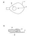
図1a)には本発明に係る創傷治療装置の吸込接続部10を下から見た図、図1b)には図1a)
による吸込接続部10を上から見た図、そして図1c)には本発明に係る吸込接続部10の断面
図がそれぞれ示してある。FIG. 1a) shows the
The
図1に示す吸込接続部10がフランジ状当接領域11を有し、この当接領域は突起なしの平
坦な円板状当接面12を備えている。この当接面12に吸引孔14が穿設されている。やはり円形の吸引孔14は当接面12の中心に配置されている。吸引孔14が結合部材20に注ぐ。この結合部材は接続管の態様に実施されており、当接面12に垂直に向けられた滲出液流れの90°方向転換を引き起こし、この流れは方向転換後に当接面12とほぼ平行に向けられている。接続管20は吸引孔14から離れた方のその末端に内径を拡張された接続領域22を有し、この接続領域に吸引チューブ30が空気密に導入可能である。接続管20を頼りに吸引流れを方向転換することによって、当接面12と平行な方向に吸引チューブ30を向けることが可能となる。これにより吸込接続部10およびこれと結合された吸引チューブ30を患者の身体にほぼ支障なく当接させることが可能となる。The
図1c)に示す実施形態では吸引チューブ30は、その内周面が接続管20の接続領域22に隣
接する内面領域と一直線に並び、こうして創傷滲出液に対する流れ抵抗が最小となるように寸法設計されている。In the embodiment shown in FIG. 1c), the
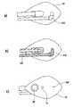
図2a)による実施形態では、当接面12の吸引孔14を含む中央領域は創傷滲出液を吸引孔14へと導くべく設計されたドレナージ層40によって覆われている。ドレナージ層40は当接
面12に貼り付けられており、当接面12の固着領域16によって環状に取り囲まれる。In the embodiment according to FIG. 2a), the central region of the
図2b)による実施形態では当接面12がドレナージ層40によって完全に覆われている。吸
込接続部10の当接面12から離れた方の周面には接続管20を取り囲む固着領域16‘が設けられており、この固着領域は固着領域16と同様に接着層を備えておくことができ、この接着層は本発明に係る創傷治療装置内で吸込接続部10を利用する前、剥離可能な保護層によって覆っておくことができる。In the embodiment according to FIG. 2b), the
図3による吸込接続部が図1、図2による吸込接続部と相違しているのは実質的に、当接
領域11が吸引孔14を補足してなお1つの通気孔80も有し、この通気孔を通して制御下に創
傷に通気し、こうして滲出液の排出を改善する意味で創傷領域内の流れ条件を改善できることによってである。通気孔80は吸引孔14よりも大きな直径を有する。通気孔80を当接領域11内で取り囲む縁部は段差を有することができ、この段差は図4、図5によれば抗菌フィルタ82用載置面として利用することができる。これにより通気孔80の領域で流れ抵抗が強まるが、しかしながらこれは通気孔80の直径を調整することによって再び補償することができる。The suction connection according to FIG. 3 differs from the suction connection according to FIGS. 1 and 2 in that the
本発明の枠内でフィルタ82の流れ抵抗は空気の流れを制御するのに利用することができる。流れ抵抗はフィルタ細孔を縮小することによって強まる。この制御は通気と同時に陰圧の発生を促進する。通気孔80が過度に大きく選択されるなら、陰圧はフィルタを利用することなくして発生することができない。通気孔80は水蒸気透過性被覆フィルム60の(平面図で)上に配置しておくこともできる。大切なのは創傷に空気が供給されることである。このため、空気が円滑に通気孔80へと流れることがでるように被覆フィルム60に穴を多少ずらして設けると望ましいことがある。 Within the framework of the present invention, the flow resistance of the
抗菌フィルタ82は図面に示した実施形態においてポリテトラフルオロエチレンで形成されており、細孔寸法が0.001、特に0.005、好ましくは0.02、特別好ましくは0.1〜5マイクロメートルの範囲内である。図6a、図6bによる創傷治療装置においてフィルタはドレナージ層40によって覆われる。図4を基に説明したように、図3による吸込接続部は図1による
吸込接続部と同様に、被覆フィルム60に貼り付けられているように取り付けることができる。The
図5による実施形態が図3による実施形態と相違しているのは実質的に、吸引チューブがトリプルルーメンチューブ32として実現されていることによってであり、図6に概略示唆
したように中央の最大ルーメン34は創傷領域に陰圧を発生するのに利用され、小さなルーメン36は創傷の通気に利用することができ、一層小さなルーメン38は創傷領域内での圧力測定を想定されている。接続領域22はやはりルーメン32、34、36に対応したルーメン24、26、28を有する。The embodiment according to FIG. 5 differs from the embodiment according to FIG. 3 substantially due to the fact that the suction tube is realized as a
図5、図6による実施形態は、滲出液の管理をさらに改善できるようにするために通気ルーメン26の他になお1つの通気孔80も有する。 The embodiments according to FIGS. 5 and 6 also have one
図7による実施形態が図3による実施形態と相違しているのは実質的に、吸引孔14および通気孔80を補足して吸込接続部10の当接領域11になお1つの供給孔100も設けられており、供給孔100を他のチューブ130と結合する他の接続管110がこの供給孔に付設されているこ
とによってである。チューブ130と他の接続管110と供給孔100とを介して創傷治療剤、例
えば場合によって薬剤、消毒剤等々とも混合された洗浄溶液は創傷領域に持ち込むことができる。図7による実施形態は、供給孔100が通気にも利用できるので、個別の通気孔80を用いることなく利用することもできる。しかしながら滲出液を良好に管理する意味で特別望ましいと実証されたのは、通気孔80も供給孔100も吸込接続部10の当接領域11で吸引孔14の横に設けられていることである。The embodiment according to FIG. 7 is substantially different from the embodiment according to FIG. 3 in that the
図8に認めることができるように、洗浄溶液は他のチューブ130と他の接続管110とを介
して当該調量要素114を頼りに創傷領域に持ち込むことができる。その際特別望ましいと
実証されたのは、供給孔100がドレナージ層40によって覆われるのでなく、供給される洗
浄溶液による影響を受けることなく創傷滲出液の吸引をこうして保証し、供給された洗浄溶液が直ちに再び吸引されるのを防止することである。As can be seen in FIG. 8, the wash solution can be brought into the wound area via the
図9による実施形態が図7を基に説明した実施形態と相違しているのは、図5による実施
に匹敵する実施および機能のトリプルルーメンチューブ132が利用されていることによっ
てである。このため図9による実施は創傷滲出液の吸引と創傷領域の通気と圧力測定とを
行うトリプルルーメンチューブと、通気孔80と、供給孔100とを有する。これにより最適
な創傷管理は保証することができる。The embodiment according to FIG. 9 differs from the embodiment described with reference to FIG. 7 due to the use of a
図3〜図9を基に説明した実施形態は、図1、図2を基に説明した実施形態とは異なり、円形状とは異なる形状、つまり例えば菱形形状の当接領域を有する。菱形の角は丸められている。この菱形形状によって、吸引孔と通気孔と供給孔とを一直線上に配置することを可能とする縦軸が用意される。 The embodiment described with reference to FIGS. 3 to 9 has a shape different from the circular shape, that is, a rhombus-shaped contact region, unlike the embodiment described with reference to FIGS. 1 and 2. The corners of the rhombus are rounded. This diamond shape provides a vertical axis that allows the suction holes, ventilation holes, and supply holes to be arranged in a straight line.
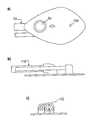
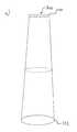
図10a)に示す被覆部材は、正円柱外被形状とすることのできるフィルムチューブ200の
態様に実施されている。図10a)に示したフィルムチューブの両方の末端210、212は、チューブをそっくり四肢に被着できるように開口して実施されている。図10b)による本発明に係る被覆部材が図10a)による被覆部材と相違しているのは実質的に、中空チューブ200の
上側末端210‘が閉鎖されていることによってである。The covering member shown in FIG. 10a) is implemented in the form of a
図10c)による実施形態では、フィルムチューブとして実施される被覆部材が円錐台外被形状に、つまり円錐状に拡張可能である。その際一方の末端、例えば上側末端310は閉鎖
しておくことができ、他方の例えば下側の末端312は開口して形成しておくことができる
。特別好ましくは、横断面の小さい方の末端が閉鎖されている。その場合フィルムチューブは例えばストッキングの方式で足に装着し、または場合によっては手袋の方式で手に装着することができる。In the embodiment according to FIG. 10c), the covering member implemented as a film tube can be expanded into a truncated cone shape, that is, a conical shape. At that time, one end, for example, the
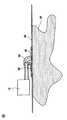
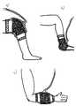
図11には本発明に係る創傷治療装置のさまざまな応用例が示してある。図11a)は膝関節領域での応用を示す。認めることができるように、被覆部材は図10c)または図10a)に示した被覆部材の態様で両側が開口したチューブ状に実施されており、相反する末端が粘着剤を頼りに周囲皮膚に固着されている。 FIG. 11 shows various application examples of the wound treatment device according to the present invention. Figure 11a) shows the application in the knee joint area. As can be seen, the covering member is implemented in a tubular shape with both sides open in the manner of the covering member shown in Fig. 10c) or Fig. 10a), and the opposite ends stick to the surrounding skin by relying on the adhesive. Has been done.
図11b)による応用例では創傷治療装置が踝に当接されている。この例において被覆部材は、利用者のふくらはぎ領域で周囲皮膚に固着される閉鎖フィルムチューブの方式に実施されている。 In the application example shown in Fig. 11b), the wound treatment device is in contact with the ankle. In this example, the covering member is implemented in the form of a closed film tube that is anchored to the surrounding skin in the user's calf area.
最後に図11c)に示す応用例では創傷治療装置が患者の前腕に当接されている。この例では被覆部材が両側の開口したフィルムチューブとして実施されており、フィルムチューブは図10c)の図示に相応して円錐状に実施され、両方の反対側縁部が周囲皮膚に付着させて固着されている。 Finally, in the application shown in Fig. 11c), the wound treatment device is in contact with the patient's forearm. In this example, the covering member is implemented as a film tube with openings on both sides, the film tube is implemented in a conical shape as shown in Fig. 10c), and both opposite edges adhere to and adhere to the surrounding skin. Has been done.
本発明は、図面を基に説明した実施形態に限定されていない。特に、場合によって支持フィルムに被着しておくこともできるチューブ状被覆フィルムの利用が想定されており、被覆フィルムを創傷に当接後に支持フィルムは被覆フィルムから剥がすことができる。その際望ましくは周方向で完全に閉鎖されたチューブフィルムが利用され、このチューブフィルムは少なくとも一方の軸線方向末端にのみ1つの孔を有し、吸込接続部を介して滲出
液を導出するのに必要なチューブフィルムの孔はチューブフィルムを創傷に当接後に形成される。このためチューブフィルムは例えば適切な箇所で切り開くことができる。ポリウレタンフィルムの他に、別の皮膚適合性で水蒸気透過性のフィルムを利用することもできる。重要なのは、被覆部材が実質的に空気密、水密に密閉創傷空間を限定し、耐菌性で好適な水蒸気透過率を有し、生体親和性で皮膚に優しく、切断可能であり、場合によっては付加的支持フィルムを利用して容易に応用できることである。The present invention is not limited to the embodiments described with reference to the drawings. In particular, the use of a tubular coating film that can be adhered to the support film in some cases is assumed, and the support film can be peeled off from the coating film after the coating film is brought into contact with the wound. Desirably, a tube film that is completely closed in the circumferential direction is utilized, and this tube film has only one hole at at least one axial end to derive the exudate through the suction connection. The required tube film holes are formed after the tube film is brought into contact with the wound. Therefore, the tube film can be cut open at an appropriate place, for example. In addition to polyurethane films, other skin-compatible, water vapor permeable films can also be used. Importantly, the covering member is substantially airtight and watertight, limiting the closed wound space, having bacterial resistance and suitable water vapor permeability, biocompatibility, skin-friendly, cuttable and, in some cases, cutable. It can be easily applied by using an additional support film.
抗菌フィルタ82は図面に示した実施形態においてポリテトラフルオロエチレンで形成されており、細孔寸法が0.001、特に0.005、好ましくは0.02、特別好ましくは0.1〜5マイクロメートルの範囲内である。図4による創傷治療装置においてフィルタはドレナージ層40によって覆われる。図4を基に説明したように、図3による吸込接続部は図1による吸込接続部と同様に、被覆フィルム60に貼り付けられているように取り付けることができる。The
図5による実施形態が図3による実施形態と相違しているのは実質的に、吸引チューブがトリプルルーメンチューブ32として実現されていることによってであり、図6に概略示唆したように中央の最大ルーメン34は創傷領域に陰圧を発生するのに利用され、小さなルーメン36は創傷の通気に利用することができ、一層小さなルーメン38は創傷領域内での圧力測定を想定されている。接続領域22はやはりルーメン34、36、38に対応したルーメン24、26、28を有する。The embodiment according to FIG. 5 differs from the embodiment according to FIG. 3 substantially due to the fact that the suction tube is realized as a
Claims (18)
Translated fromJapaneseh以上、特別好ましくは750 g/m2/24 hであることを特徴とする請求項1記載の創傷治療
装置。The water vapor permeability of the covering member at least partially in the 300 g / m2/24 h or more, particularly 500 g / m2/24
h or more, the wound treatment device according to claim 1, wherein the special preferably750 g / m 2/24 h .
好ましくは3000 g/m2/24 h以下であることを特徴とする請求項1または2記載の創傷治療装置。Claims, characterized in that the water vapor permeability of the covering member 10000 g / m less than2/24 h, in particular less than5000 g / m 2/24 h , special preferably not more than 3000 g / m2/24 h 1 or 2 Wound Healing Device.
ずれか1項記載の創傷治療装置。The wound treatment apparatus according to any one of claims 1 to 4, wherein the covering member has an elongation at the time of tearing of 100% or more.
る請求項1〜8のいずれか1項記載の創傷治療装置。A filler designed to fill the wound space between the wound bed and the covering member and exudate to be sucked from the filler, primarily on the side of the suction connection facing the filler. The wound healing apparatus according to any one of claims 1 to 8, wherein a drainage layer is provided leading to at least one suction hole of the suction connection portion.
治療装置。The wound treatment apparatus according to any one of claims 1 to 13, wherein a support member that can be peeled off from the wound after abutting on the wound, particularly a support film, is attached to the covering member.
Priority Applications (1)
| Application Number | Priority Date | Filing Date | Title |
|---|---|---|---|
| JP2022094905AJP2022126722A (en) | 2012-03-05 | 2022-06-13 | wound treatment device |
Applications Claiming Priority (2)
| Application Number | Priority Date | Filing Date | Title |
|---|---|---|---|
| EP12002332.0 | 2012-03-05 | ||
| EP12002332.0AEP2636417B1 (en) | 2012-03-05 | 2012-03-05 | Wound treatment assembly and covering device for same |
Related Parent Applications (1)
| Application Number | Title | Priority Date | Filing Date |
|---|---|---|---|
| JP2018007077ADivisionJP2018083099A (en) | 2012-03-05 | 2018-01-19 | Wound care arrangement |
Related Child Applications (1)
| Application Number | Title | Priority Date | Filing Date |
|---|---|---|---|
| JP2022094905ADivisionJP2022126722A (en) | 2012-03-05 | 2022-06-13 | wound treatment device |
Publications (1)
| Publication Number | Publication Date |
|---|---|
| JP2020146483Atrue JP2020146483A (en) | 2020-09-17 |
Family
ID=47827132
Family Applications (4)
| Application Number | Title | Priority Date | Filing Date |
|---|---|---|---|
| JP2014560269APendingJP2015513424A (en) | 2012-03-05 | 2013-03-05 | Wound treatment device and covering member therefor |
| JP2018007077APendingJP2018083099A (en) | 2012-03-05 | 2018-01-19 | Wound care arrangement |
| JP2020091866APendingJP2020146483A (en) | 2012-03-05 | 2020-05-27 | Wound care arrangement |
| JP2022094905APendingJP2022126722A (en) | 2012-03-05 | 2022-06-13 | wound treatment device |
Family Applications Before (2)
| Application Number | Title | Priority Date | Filing Date |
|---|---|---|---|
| JP2014560269APendingJP2015513424A (en) | 2012-03-05 | 2013-03-05 | Wound treatment device and covering member therefor |
| JP2018007077APendingJP2018083099A (en) | 2012-03-05 | 2018-01-19 | Wound care arrangement |
Family Applications After (1)
| Application Number | Title | Priority Date | Filing Date |
|---|---|---|---|
| JP2022094905APendingJP2022126722A (en) | 2012-03-05 | 2022-06-13 | wound treatment device |
Country Status (15)
| Country | Link |
|---|---|
| US (2) | US20150045752A1 (en) |
| EP (2) | EP2636417B1 (en) |
| JP (4) | JP2015513424A (en) |
| KR (2) | KR20140137405A (en) |
| CN (1) | CN104363932B (en) |
| AU (2) | AU2013230315B2 (en) |
| BR (1) | BR112014021721B1 (en) |
| CA (1) | CA2866454C (en) |
| CL (1) | CL2014002365A1 (en) |
| DE (1) | DE202013012333U1 (en) |
| IN (1) | IN2014DN07412A (en) |
| MX (1) | MX369045B (en) |
| RU (1) | RU2613604C2 (en) |
| WO (1) | WO2013131638A1 (en) |
| ZA (1) | ZA201406389B (en) |
Families Citing this family (70)
| Publication number | Priority date | Publication date | Assignee | Title |
|---|---|---|---|---|
| GB0723872D0 (en) | 2007-12-06 | 2008-01-16 | Smith & Nephew | Apparatus for topical negative pressure therapy |
| AU2009221772B2 (en) | 2008-03-05 | 2015-01-22 | Solventum Intellectual Properties Company | Dressing and method for applying reduced pressure to and collecting and storing fluid from a tissue site |
| GB0808376D0 (en) | 2008-05-08 | 2008-06-18 | Bristol Myers Squibb Co | Wound dressing |
| GB0817796D0 (en) | 2008-09-29 | 2008-11-05 | Convatec Inc | wound dressing |
| US8814842B2 (en) | 2010-03-16 | 2014-08-26 | Kci Licensing, Inc. | Delivery-and-fluid-storage bridges for use with reduced-pressure systems |
| GB201020236D0 (en) | 2010-11-30 | 2011-01-12 | Convatec Technologies Inc | A composition for detecting biofilms on viable tissues |
| WO2012078724A1 (en) | 2010-12-08 | 2012-06-14 | Convatec Technologies Inc. | Apparatus and method for applying pressure to a wound site |
| ES2748519T3 (en) | 2010-12-08 | 2020-03-17 | Convatec Technologies Inc | Wound exudate system accessory |
| US10207031B2 (en) | 2010-12-08 | 2019-02-19 | Convatec Technologies Inc. | Integrated system for assessing wound exudates |
| GB201115182D0 (en) | 2011-09-02 | 2011-10-19 | Trio Healthcare Ltd | Skin contact material |
| GB2497406A (en) | 2011-11-29 | 2013-06-12 | Webtec Converting Llc | Dressing with a perforated binder layer |
| GB201120693D0 (en) | 2011-12-01 | 2012-01-11 | Convatec Technologies Inc | Wound dressing for use in vacuum therapy |
| US10940047B2 (en) | 2011-12-16 | 2021-03-09 | Kci Licensing, Inc. | Sealing systems and methods employing a hybrid switchable drape |
| CN103987348B (en) | 2011-12-16 | 2016-05-11 | 凯希特许有限公司 | Releasable Medical Drapes |
| EP2636417B1 (en) | 2012-03-05 | 2017-04-26 | Lohmann & Rauscher GmbH | Wound treatment assembly and covering device for same |
| JP6250571B2 (en) | 2012-03-12 | 2017-12-20 | スミス アンド ネフュー ピーエルシーSmith & Nephew Public Limited Company | Pressure reducing apparatus and method |
| AU2013344686B2 (en) | 2012-11-16 | 2018-06-21 | Solventum Intellectual Properties Company | Medical drape with pattern adhesive layers and method of manufacturing same |
| JP2016507663A (en) | 2012-12-20 | 2016-03-10 | コンバテック・テクノロジーズ・インコーポレイテッドConvatec Technologies Inc | Processing of chemically modified cellulosic fibers |
| CA2926370C (en)* | 2013-10-10 | 2018-06-26 | F. Hoffmann-La Roche Ag | Carrier system for an object worn on the body and method of production |
| US10946124B2 (en) | 2013-10-28 | 2021-03-16 | Kci Licensing, Inc. | Hybrid sealing tape |
| EP3062751B1 (en) | 2013-10-30 | 2017-08-09 | KCI Licensing, Inc. | Condensate absorbing and dissipating system |
| AU2014342903B2 (en) | 2013-10-30 | 2018-09-20 | Solventum Intellectual Properties Company | Dressing with differentially sized perforations |
| US9956120B2 (en) | 2013-10-30 | 2018-05-01 | Kci Licensing, Inc. | Dressing with sealing and retention interface |
| EP3527237B1 (en)* | 2013-10-30 | 2020-09-09 | KCI Licensing, Inc. | Absorbent conduit and system |
| US11026844B2 (en) | 2014-03-03 | 2021-06-08 | Kci Licensing, Inc. | Low profile flexible pressure transmission conduit |
| JP6640748B2 (en) | 2014-06-05 | 2020-02-05 | ケーシーアイ ライセンシング インコーポレイテッド | Dressing with fluid acquisition and dispensing features |
| WO2016100098A1 (en) | 2014-12-17 | 2016-06-23 | Kci Licensing, Inc. | Dressing with offloading capability |
| DK3288508T3 (en) | 2015-04-27 | 2020-03-09 | Smith & Nephew | REDUCED PRESSURE DEVICES |
| EP3574877B1 (en) | 2015-05-08 | 2022-08-17 | 3M Innovative Properties Company | Low-acuity dressing with integral pump |
| EP3117806B1 (en)* | 2015-07-16 | 2020-06-10 | Lohmann & Rauscher GmbH | Wound treatment assembly |
| EP3120817B1 (en) | 2015-07-22 | 2020-07-01 | Lohmann & Rauscher GmbH | Wound treatment assembly |
| EP3741335B1 (en) | 2015-09-01 | 2023-05-24 | KCI Licensing, Inc. | Dressing with increased apposition force |
| US20170079756A1 (en)* | 2015-09-17 | 2017-03-23 | Karrie Lynn Velky | Hands-free dental suction assembly |
| EP3349807B1 (en) | 2015-09-17 | 2021-02-24 | 3M Innovative Properties Company | Hybrid silicone and acrylic adhesive cover for use with wound treatment |
| GB2543544A (en) | 2015-10-21 | 2017-04-26 | Brightwake Ltd | Wound dressing |
| DE102016000569B3 (en)* | 2016-01-20 | 2017-06-22 | Lohmann & Rauscher Gmbh | Method for producing a film tube |
| EP3426206B1 (en) | 2016-03-07 | 2023-05-10 | Smith & Nephew plc | Wound treatment apparatuses and methods with negative pressure source integrated into wound dressing |
| AU2017243601A1 (en) | 2016-03-30 | 2018-11-22 | Acib Gmbh | Detecting microbial infection in wounds |
| PL3435941T3 (en) | 2016-03-30 | 2022-05-09 | Convatec Technologies Inc. | Detecting microbial infections in wounds |
| CA3022184A1 (en) | 2016-04-26 | 2017-11-02 | Smith & Nephew Plc | Wound dressings and methods of use with integrated negative pressure source having a fluid ingress inhibition component |
| WO2017191158A1 (en) | 2016-05-03 | 2017-11-09 | Smith & Nephew Plc | Systems and methods for driving negative pressure sources in negative pressure therapy systems |
| US11096831B2 (en) | 2016-05-03 | 2021-08-24 | Smith & Nephew Plc | Negative pressure wound therapy device activation and control |
| CA3038206A1 (en) | 2016-05-03 | 2017-11-09 | Smith & Nephew Plc | Optimizing power transfer to negative pressure sources in negative pressure therapy systems |
| DK3481349T3 (en) | 2016-07-08 | 2021-07-12 | Convatec Technologies Inc | Flexible vacuum system |
| MX2019000232A (en) | 2016-07-08 | 2019-11-12 | Convatec Technologies Inc | Fluid flow sensing. |
| EP3481348A4 (en) | 2016-07-08 | 2020-02-26 | ConvaTec Technologies Inc. | Fluid collection apparatus |
| CN109789037A (en)* | 2016-08-19 | 2019-05-21 | T.J.史密夫及内修有限公司 | For monitoring patient mobile Reduced pressure treatment system and method |
| WO2018037075A1 (en) | 2016-08-25 | 2018-03-01 | Smith & Nephew Plc | Absorbent negative pressure wound therapy dressing |
| EP3519001B1 (en) | 2016-09-30 | 2025-05-21 | Smith & Nephew plc | Negative pressure wound treatment apparatuses and methods with integrated electronics |
| DE102016014190A1 (en)* | 2016-11-28 | 2018-05-30 | Lohmann & Rauscher Gmbh | Drainage tube and treatment kit with drainage tube |
| EP3551244A1 (en) | 2016-12-12 | 2019-10-16 | Smith & Nephew PLC | Pressure wound therapy status indication via external device |
| EP3592312B1 (en) | 2017-03-08 | 2024-01-10 | Smith & Nephew plc | Negative pressure wound therapy device control in presence of fault condition |
| DE102017003826A1 (en) | 2017-04-20 | 2018-10-25 | Lohmann & Rauscher Gmbh | Wound treatment arrangement for the negative pressure therapy |
| JP7121050B2 (en) | 2017-05-09 | 2022-08-17 | スミス アンド ネフュー ピーエルシー | Redundant control of negative pressure wound therapy systems |
| CA3074780A1 (en) | 2017-09-13 | 2019-03-21 | Smith & Nephew Plc | Negative pressure wound treatment apparatuses and methods with integrated electronics |
| GB201718070D0 (en) | 2017-11-01 | 2017-12-13 | Smith & Nephew | Negative pressure wound treatment apparatuses and methods with integrated electronics |
| GB201718054D0 (en) | 2017-11-01 | 2017-12-13 | Smith & Nephew | Sterilization of integrated negative pressure wound treatment apparatuses and sterilization methods |
| GB201718072D0 (en) | 2017-11-01 | 2017-12-13 | Smith & Nephew | Negative pressure wound treatment apparatuses and methods with integrated electronics |
| US11497653B2 (en) | 2017-11-01 | 2022-11-15 | Smith & Nephew Plc | Negative pressure wound treatment apparatuses and methods with integrated electronics |
| CN111836655A (en) | 2017-11-16 | 2020-10-27 | 康沃特克有限公司 | fluid collection equipment |
| CA3084180A1 (en) | 2017-12-06 | 2019-06-13 | Cornell University | Manually-operated negative pressure wound therapy (npwt) bandage with improved pump efficiency, automatic pressure indicator and automatic pressure limiter |
| EP3781223B2 (en) | 2018-04-18 | 2025-06-11 | ConvaTec Limited | Wound care system for negative pressure therapy |
| USD898925S1 (en) | 2018-09-13 | 2020-10-13 | Smith & Nephew Plc | Medical dressing |
| GB201903774D0 (en) | 2019-03-20 | 2019-05-01 | Smith & Nephew | Negative pressure wound treatment apparatuses and methods with integrated electronics |
| GB201907716D0 (en) | 2019-05-31 | 2019-07-17 | Smith & Nephew | Systems and methods for extending operational time of negative pressure wound treatment apparatuses |
| EP4295869A3 (en) | 2019-06-03 | 2024-03-20 | Convatec Limited | Methods and devices to disrupt and contain pathogens |
| US11331221B2 (en) | 2019-12-27 | 2022-05-17 | Convatec Limited | Negative pressure wound dressing |
| US11771819B2 (en) | 2019-12-27 | 2023-10-03 | Convatec Limited | Low profile filter devices suitable for use in negative pressure wound therapy systems |
| WO2021161116A1 (en)* | 2020-02-13 | 2021-08-19 | Rezaee Mehdi | Surgical hemo-vac drain with epidural drug delivery system |
| US20250195741A1 (en)* | 2022-03-25 | 2025-06-19 | Osaka University | Wound treatment device and wound covering used therein |
Citations (4)
| Publication number | Priority date | Publication date | Assignee | Title |
|---|---|---|---|---|
| JPS6396847U (en)* | 1986-12-12 | 1988-06-22 | ||
| JP2010000159A (en)* | 2008-06-19 | 2010-01-07 | Alcare Co Ltd | Instrument for wound and apparatus for wound using the instrument for wound |
| WO2010141030A1 (en)* | 2009-06-01 | 2010-12-09 | Tyco Healthcare Group Lp | System for providing continual drainage in negative pressure wound therapy |
| WO2011090986A2 (en)* | 2010-01-20 | 2011-07-28 | Kci Licensing, Inc. | Wound-connection pads for fluid instillation and negative pressure wound therapy, and systems and methods |
Family Cites Families (49)
| Publication number | Priority date | Publication date | Assignee | Title |
|---|---|---|---|---|
| US4846164A (en) | 1987-08-07 | 1989-07-11 | Martz Joel D | Vapor permeable dressing |
| US5425702A (en) | 1989-11-20 | 1995-06-20 | Sunmed, Inc. | Soft tissue support for hip and shoulder |
| GB2265314B (en)* | 1989-11-29 | 1994-05-18 | South Glamorgan Health Authori | Protective articles. |
| WO1992019194A1 (en)* | 1991-05-07 | 1992-11-12 | Kotec Limited | Wound covering material |
| US5645081A (en) | 1991-11-14 | 1997-07-08 | Wake Forest University | Method of treating tissue damage and apparatus for same |
| RU2125859C1 (en)* | 1995-06-01 | 1999-02-10 | Открытое акционерное общество "Научно-исследовательский и проектный институт мономеров с опытным заводом" | Medical bandage |
| GB9523253D0 (en) | 1995-11-14 | 1996-01-17 | Mediscus Prod Ltd | Portable wound treatment apparatus |
| US7214202B1 (en) | 1997-07-28 | 2007-05-08 | Kci Licensing, Inc. | Therapeutic apparatus for treating ulcers |
| GB9719520D0 (en) | 1997-09-12 | 1997-11-19 | Kci Medical Ltd | Surgical drape and suction heads for wound treatment |
| MXPA01007589A (en) | 1999-01-26 | 2003-06-24 | Ark Therapeutics Ltd | Protective cover for injured limbs. |
| GB9909301D0 (en)* | 1999-04-22 | 1999-06-16 | Kci Medical Ltd | Wound treatment apparatus employing reduced pressure |
| JP3581064B2 (en) | 1999-11-10 | 2004-10-27 | 株式会社マキタ | Charging device |
| US6471685B1 (en)* | 2000-05-18 | 2002-10-29 | David James Johnson | Medical dressing assembly and associated method of using the same |
| EP1487389B1 (en) | 2002-02-28 | 2011-10-05 | KCI Medical Resources | External catheter access to vacuum bandage |
| DE10223290A1 (en)* | 2002-05-24 | 2003-12-11 | Mayfran Int Bv | Device for receiving and separating chips and coolant (drive) from machine tools |
| US7520872B2 (en)* | 2002-09-13 | 2009-04-21 | Neogen Technologies, Inc. | Closed wound drainage system |
| GB0224986D0 (en)* | 2002-10-28 | 2002-12-04 | Smith & Nephew | Apparatus |
| US7942866B2 (en)* | 2003-08-28 | 2011-05-17 | Boehringer Technologies, L.P. | Device for treating a wound |
| US8100887B2 (en)* | 2004-03-09 | 2012-01-24 | Bluesky Medical Group Incorporated | Enclosure-based reduced pressure treatment system |
| US7776028B2 (en)* | 2004-04-05 | 2010-08-17 | Bluesky Medical Group Incorporated | Adjustable overlay reduced pressure wound treatment system |
| JP5555828B2 (en) | 2005-06-29 | 2014-07-23 | アプライド ティッシュ テクノロジーズ リミテッド ライアビリティ カンパニー | Wound chamber for limbs |
| US20070032755A1 (en)* | 2005-08-02 | 2007-02-08 | Medica-Rents Co., Ltd. | Method and apparatus for treating a wound |
| EP1986718B1 (en)* | 2006-02-06 | 2015-10-28 | KCI Licensing, Inc. | Systems for improved connection to wound dressings in conjunction with reduced pressure wound treatment systems |
| GB0712735D0 (en) | 2006-07-26 | 2007-08-08 | Smith & Nephew | Dressing |
| US7931651B2 (en) | 2006-11-17 | 2011-04-26 | Wake Lake University Health Sciences | External fixation assembly and method of use |
| RU70627U1 (en)* | 2007-09-17 | 2008-02-10 | Вадим Владимирович Белов | DEVICE FOR VACUUM THERAPY OF PURULENT RAS |
| GB0723872D0 (en)* | 2007-12-06 | 2008-01-16 | Smith & Nephew | Apparatus for topical negative pressure therapy |
| JP5246397B2 (en)* | 2007-12-20 | 2013-07-24 | アルケア株式会社 | Wound bag and drainage management tool or negative pressure closure therapy tool using the wound bag |
| US8021347B2 (en) | 2008-07-21 | 2011-09-20 | Tyco Healthcare Group Lp | Thin film wound dressing |
| BRPI0906527A2 (en)* | 2008-04-04 | 2016-09-06 | 3Mm Innovative Properties Company | apparatus for applying bandages to wounds and medical bandages |
| WO2009124548A1 (en) | 2008-04-11 | 2009-10-15 | Coloplast A/S | Wound cover device |
| JP2009273669A (en)* | 2008-05-15 | 2009-11-26 | Alcare Co Ltd | Sheet body for instrument for wound, and instrument for wound and device for wound using this sheet body |
| KR20100007548A (en) | 2008-07-14 | 2010-01-22 | 주식회사 바이오알파 | Medical suction head |
| WO2010011148A1 (en) | 2008-07-24 | 2010-01-28 | Frederick George | Negative pressure wound therapy system |
| US8216198B2 (en) | 2009-01-09 | 2012-07-10 | Tyco Healthcare Group Lp | Canister for receiving wound exudate in a negative pressure therapy system |
| US8158844B2 (en)* | 2008-10-08 | 2012-04-17 | Kci Licensing, Inc. | Limited-access, reduced-pressure systems and methods |
| GB0905290D0 (en)* | 2009-03-27 | 2009-05-13 | First Water Ltd | Multilayer compositions and dressings |
| DE102009019646B4 (en) | 2009-04-30 | 2015-04-30 | Lohmann & Rauscher Gmbh | Wound covering and method of manufacture |
| US9452247B2 (en)* | 2009-12-16 | 2016-09-27 | Paul Hartmann Ag | Device for negative pressure wound therapy |
| US8430867B2 (en)* | 2010-03-12 | 2013-04-30 | Kci Licensing, Inc. | Reduced-pressure dressing connection pads, systems, and methods |
| US8604265B2 (en)* | 2010-04-16 | 2013-12-10 | Kci Licensing, Inc. | Dressings and methods for treating a tissue site on a patient |
| GB201008347D0 (en) | 2010-05-19 | 2010-07-07 | Smith & Nephew | Wound protection |
| WO2012083935A1 (en) | 2010-12-23 | 2012-06-28 | Alfons Erdmann | Device for suctioning a fluid from a cover of a body part |
| DE102011106540A1 (en) | 2010-12-23 | 2012-06-28 | Alfons Erdmann | Gas-tight cover for pipe used in medical field, has sleeve portion designed as prism with three lateral surfaces that adjoin one another at acute angles in cross-section of prism |
| EP2495009A1 (en) | 2011-03-02 | 2012-09-05 | Lohmann & Rauscher GmbH | Wound treatment assembly and suction attachment for same |
| DE102012205408A1 (en) | 2011-04-09 | 2012-10-11 | Klaus Junig | Device for squeezing out tissue fluid of leg for treatment of edema, has pump in fluid communication with interior of sleeve, and control unit for alternately controlling pump and valve that is in fluid communication with sleeve interior |
| US20130046223A1 (en)* | 2011-08-15 | 2013-02-21 | Stephen Schrammel | Long Term Wound Dressing |
| EP2636417B1 (en) | 2012-03-05 | 2017-04-26 | Lohmann & Rauscher GmbH | Wound treatment assembly and covering device for same |
| EP3831350B1 (en) | 2013-08-12 | 2022-11-23 | BSN medical GmbH | Wound care article having a substantially polygonal or ellipsoid main surface and at least one recess arranged on one side |
- 2012
- 2012-03-05EPEP12002332.0Apatent/EP2636417B1/enactiveActive
- 2013
- 2013-03-05USUS14/382,971patent/US20150045752A1/ennot_activeAbandoned
- 2013-03-05KRKR20147027604Apatent/KR20140137405A/ennot_activeCeased
- 2013-03-05AUAU2013230315Apatent/AU2013230315B2/enactiveActive
- 2013-03-05CNCN201380012328.9Apatent/CN104363932B/enactiveActive
- 2013-03-05JPJP2014560269Apatent/JP2015513424A/enactivePending
- 2013-03-05WOPCT/EP2013/000636patent/WO2013131638A1/enactiveApplication Filing
- 2013-03-05CACA2866454Apatent/CA2866454C/enactiveActive
- 2013-03-05EPEP13707554.5Apatent/EP2822613B1/enactiveActive
- 2013-03-05DEDE202013012333.8Upatent/DE202013012333U1/ennot_activeExpired - Lifetime
- 2013-03-05KRKR1020207001889Apatent/KR102235586B1/enactiveActive
- 2013-03-05RURU2014140148Apatent/RU2613604C2/enactive
- 2013-03-05MXMX2014010624Apatent/MX369045B/enactiveIP Right Grant
- 2013-03-05ININ7412DEN2014patent/IN2014DN07412A/enunknown
- 2013-03-05BRBR112014021721-1Apatent/BR112014021721B1/enactiveIP Right Grant
- 2014
- 2014-08-29ZAZA2014/06389Apatent/ZA201406389B/enunknown
- 2014-09-05CLCL2014002365Apatent/CL2014002365A1/enunknown
- 2017
- 2017-11-24AUAU2017265141Apatent/AU2017265141A1/ennot_activeAbandoned
- 2018
- 2018-01-19JPJP2018007077Apatent/JP2018083099A/enactivePending
- 2019
- 2019-11-14USUS16/683,982patent/US11752040B2/enactiveActive
- 2020
- 2020-05-27JPJP2020091866Apatent/JP2020146483A/enactivePending
- 2022
- 2022-06-13JPJP2022094905Apatent/JP2022126722A/enactivePending
Patent Citations (4)
| Publication number | Priority date | Publication date | Assignee | Title |
|---|---|---|---|---|
| JPS6396847U (en)* | 1986-12-12 | 1988-06-22 | ||
| JP2010000159A (en)* | 2008-06-19 | 2010-01-07 | Alcare Co Ltd | Instrument for wound and apparatus for wound using the instrument for wound |
| WO2010141030A1 (en)* | 2009-06-01 | 2010-12-09 | Tyco Healthcare Group Lp | System for providing continual drainage in negative pressure wound therapy |
| WO2011090986A2 (en)* | 2010-01-20 | 2011-07-28 | Kci Licensing, Inc. | Wound-connection pads for fluid instillation and negative pressure wound therapy, and systems and methods |
Also Published As
| Publication number | Publication date |
|---|---|
| US11752040B2 (en) | 2023-09-12 |
| KR20200012022A (en) | 2020-02-04 |
| KR102235586B1 (en) | 2021-04-05 |
| EP2822613A1 (en) | 2015-01-14 |
| AU2013230315A1 (en) | 2014-10-02 |
| AU2017265141A1 (en) | 2017-12-14 |
| DE202013012333U1 (en) | 2016-05-11 |
| MX2014010624A (en) | 2015-03-19 |
| BR112014021721B1 (en) | 2021-01-19 |
| US20200078225A1 (en) | 2020-03-12 |
| HK1204460A1 (en) | 2015-11-20 |
| CA2866454C (en) | 2017-10-17 |
| EP2636417A1 (en) | 2013-09-11 |
| CL2014002365A1 (en) | 2015-03-27 |
| EP2822613B1 (en) | 2019-09-25 |
| CA2866454A1 (en) | 2013-09-12 |
| RU2014140148A (en) | 2016-04-27 |
| US20150045752A1 (en) | 2015-02-12 |
| IN2014DN07412A (en) | 2015-04-24 |
| EP2636417B1 (en) | 2017-04-26 |
| CN104363932A (en) | 2015-02-18 |
| AU2013230315B2 (en) | 2017-10-05 |
| ZA201406389B (en) | 2015-12-23 |
| KR20140137405A (en) | 2014-12-02 |
| JP2022126722A (en) | 2022-08-30 |
| WO2013131638A1 (en) | 2013-09-12 |
| JP2015513424A (en) | 2015-05-14 |
| CN104363932B (en) | 2019-02-12 |
| RU2613604C2 (en) | 2017-03-17 |
| JP2018083099A (en) | 2018-05-31 |
| MX369045B (en) | 2019-10-25 |
Similar Documents
| Publication | Publication Date | Title |
|---|---|---|
| JP2020146483A (en) | Wound care arrangement | |
| EP3937862B1 (en) | An ostomy wafer construction | |
| US20230103651A1 (en) | System for providing wound dressing port and associated wound dressing | |
| JP5674881B2 (en) | Equipment for local negative pressure therapy | |
| AU2009200607B2 (en) | Wound dressing port and associated wound dressing | |
| CN106999304B (en) | Wound dressing | |
| US8926574B2 (en) | Wound dressing for negative-pressure therapy | |
| EP2959933B2 (en) | Vacuum system with vacuum port for vacuum wound therapy | |
| CN109561994A (en) | Absorbability negative pressure wound therapy dressing | |
| JP5322002B2 (en) | Wound device and wound device using the wound device | |
| US20100145293A1 (en) | Apparatus and System for Isolating a Fistula | |
| HK1204460B (en) | Wound care arrangement and covering unit therefor |
Legal Events
| Date | Code | Title | Description |
|---|---|---|---|
| A521 | Request for written amendment filed | Free format text:JAPANESE INTERMEDIATE CODE: A523 Effective date:20200604 | |
| A621 | Written request for application examination | Free format text:JAPANESE INTERMEDIATE CODE: A621 Effective date:20200625 | |
| A977 | Report on retrieval | Free format text:JAPANESE INTERMEDIATE CODE: A971007 Effective date:20210419 | |
| A131 | Notification of reasons for refusal | Free format text:JAPANESE INTERMEDIATE CODE: A131 Effective date:20210427 | |
| A601 | Written request for extension of time | Free format text:JAPANESE INTERMEDIATE CODE: A601 Effective date:20210726 | |
| A521 | Request for written amendment filed | Free format text:JAPANESE INTERMEDIATE CODE: A523 Effective date:20211021 | |
| A131 | Notification of reasons for refusal | Free format text:JAPANESE INTERMEDIATE CODE: A131 Effective date:20211214 | |
| A601 | Written request for extension of time | Free format text:JAPANESE INTERMEDIATE CODE: A601 Effective date:20220307 | |
| A02 | Decision of refusal | Free format text:JAPANESE INTERMEDIATE CODE: A02 Effective date:20220802 |