JP2020142051A - Artificial knee for cruciate ligament replacement - Google Patents
Artificial knee for cruciate ligament replacementDownload PDFInfo
- Publication number
- JP2020142051A JP2020142051AJP2019206156AJP2019206156AJP2020142051AJP 2020142051 AJP2020142051 AJP 2020142051AJP 2019206156 AJP2019206156 AJP 2019206156AJP 2019206156 AJP2019206156 AJP 2019206156AJP 2020142051 AJP2020142051 AJP 2020142051A
- Authority
- JP
- Japan
- Prior art keywords
- post
- component
- knee prosthesis
- knee
- tibial
- Prior art date
- Legal status (The legal status is an assumption and is not a legal conclusion. Google has not performed a legal analysis and makes no representation as to the accuracy of the status listed.)
- Granted
Links
Images


Classifications
- A—HUMAN NECESSITIES
- A61—MEDICAL OR VETERINARY SCIENCE; HYGIENE
- A61F—FILTERS IMPLANTABLE INTO BLOOD VESSELS; PROSTHESES; DEVICES PROVIDING PATENCY TO, OR PREVENTING COLLAPSING OF, TUBULAR STRUCTURES OF THE BODY, e.g. STENTS; ORTHOPAEDIC, NURSING OR CONTRACEPTIVE DEVICES; FOMENTATION; TREATMENT OR PROTECTION OF EYES OR EARS; BANDAGES, DRESSINGS OR ABSORBENT PADS; FIRST-AID KITS
- A61F2/00—Filters implantable into blood vessels; Prostheses, i.e. artificial substitutes or replacements for parts of the body; Appliances for connecting them with the body; Devices providing patency to, or preventing collapsing of, tubular structures of the body, e.g. stents
- A61F2/02—Prostheses implantable into the body
- A61F2/30—Joints
- A61F2/38—Joints for elbows or knees
- A61F2/3836—Special connection between upper and lower leg, e.g. constrained
- A—HUMAN NECESSITIES
- A61—MEDICAL OR VETERINARY SCIENCE; HYGIENE
- A61F—FILTERS IMPLANTABLE INTO BLOOD VESSELS; PROSTHESES; DEVICES PROVIDING PATENCY TO, OR PREVENTING COLLAPSING OF, TUBULAR STRUCTURES OF THE BODY, e.g. STENTS; ORTHOPAEDIC, NURSING OR CONTRACEPTIVE DEVICES; FOMENTATION; TREATMENT OR PROTECTION OF EYES OR EARS; BANDAGES, DRESSINGS OR ABSORBENT PADS; FIRST-AID KITS
- A61F2/00—Filters implantable into blood vessels; Prostheses, i.e. artificial substitutes or replacements for parts of the body; Appliances for connecting them with the body; Devices providing patency to, or preventing collapsing of, tubular structures of the body, e.g. stents
- A61F2/02—Prostheses implantable into the body
- A61F2/30—Joints
- A61F2/38—Joints for elbows or knees
- A61F2/3859—Femoral components
- A—HUMAN NECESSITIES
- A61—MEDICAL OR VETERINARY SCIENCE; HYGIENE
- A61F—FILTERS IMPLANTABLE INTO BLOOD VESSELS; PROSTHESES; DEVICES PROVIDING PATENCY TO, OR PREVENTING COLLAPSING OF, TUBULAR STRUCTURES OF THE BODY, e.g. STENTS; ORTHOPAEDIC, NURSING OR CONTRACEPTIVE DEVICES; FOMENTATION; TREATMENT OR PROTECTION OF EYES OR EARS; BANDAGES, DRESSINGS OR ABSORBENT PADS; FIRST-AID KITS
- A61F2/00—Filters implantable into blood vessels; Prostheses, i.e. artificial substitutes or replacements for parts of the body; Appliances for connecting them with the body; Devices providing patency to, or preventing collapsing of, tubular structures of the body, e.g. stents
- A61F2/02—Prostheses implantable into the body
- A61F2/30—Joints
- A61F2/38—Joints for elbows or knees
- A61F2/3886—Joints for elbows or knees for stabilising knees against anterior or lateral dislocations
- A—HUMAN NECESSITIES
- A61—MEDICAL OR VETERINARY SCIENCE; HYGIENE
- A61F—FILTERS IMPLANTABLE INTO BLOOD VESSELS; PROSTHESES; DEVICES PROVIDING PATENCY TO, OR PREVENTING COLLAPSING OF, TUBULAR STRUCTURES OF THE BODY, e.g. STENTS; ORTHOPAEDIC, NURSING OR CONTRACEPTIVE DEVICES; FOMENTATION; TREATMENT OR PROTECTION OF EYES OR EARS; BANDAGES, DRESSINGS OR ABSORBENT PADS; FIRST-AID KITS
- A61F2/00—Filters implantable into blood vessels; Prostheses, i.e. artificial substitutes or replacements for parts of the body; Appliances for connecting them with the body; Devices providing patency to, or preventing collapsing of, tubular structures of the body, e.g. stents
- A61F2/02—Prostheses implantable into the body
- A61F2/30—Joints
- A61F2/38—Joints for elbows or knees
- A61F2/389—Tibial components
- A—HUMAN NECESSITIES
- A61—MEDICAL OR VETERINARY SCIENCE; HYGIENE
- A61F—FILTERS IMPLANTABLE INTO BLOOD VESSELS; PROSTHESES; DEVICES PROVIDING PATENCY TO, OR PREVENTING COLLAPSING OF, TUBULAR STRUCTURES OF THE BODY, e.g. STENTS; ORTHOPAEDIC, NURSING OR CONTRACEPTIVE DEVICES; FOMENTATION; TREATMENT OR PROTECTION OF EYES OR EARS; BANDAGES, DRESSINGS OR ABSORBENT PADS; FIRST-AID KITS
- A61F2/00—Filters implantable into blood vessels; Prostheses, i.e. artificial substitutes or replacements for parts of the body; Appliances for connecting them with the body; Devices providing patency to, or preventing collapsing of, tubular structures of the body, e.g. stents
- A61F2/02—Prostheses implantable into the body
- A61F2/08—Muscles; Tendons; Ligaments
- A—HUMAN NECESSITIES
- A61—MEDICAL OR VETERINARY SCIENCE; HYGIENE
- A61F—FILTERS IMPLANTABLE INTO BLOOD VESSELS; PROSTHESES; DEVICES PROVIDING PATENCY TO, OR PREVENTING COLLAPSING OF, TUBULAR STRUCTURES OF THE BODY, e.g. STENTS; ORTHOPAEDIC, NURSING OR CONTRACEPTIVE DEVICES; FOMENTATION; TREATMENT OR PROTECTION OF EYES OR EARS; BANDAGES, DRESSINGS OR ABSORBENT PADS; FIRST-AID KITS
- A61F2/00—Filters implantable into blood vessels; Prostheses, i.e. artificial substitutes or replacements for parts of the body; Appliances for connecting them with the body; Devices providing patency to, or preventing collapsing of, tubular structures of the body, e.g. stents
- A61F2/02—Prostheses implantable into the body
- A61F2/30—Joints
- A61F2002/30001—Additional features of subject-matter classified in A61F2/28, A61F2/30 and subgroups thereof
- A61F2002/30316—The prosthesis having different structural features at different locations within the same prosthesis; Connections between prosthetic parts; Special structural features of bone or joint prostheses not otherwise provided for
- A61F2002/30329—Connections or couplings between prosthetic parts, e.g. between modular parts; Connecting elements
- A61F2002/30331—Connections or couplings between prosthetic parts, e.g. between modular parts; Connecting elements made by longitudinally pushing a protrusion into a complementarily-shaped recess, e.g. held by friction fit
- A61F2002/30362—Connections or couplings between prosthetic parts, e.g. between modular parts; Connecting elements made by longitudinally pushing a protrusion into a complementarily-shaped recess, e.g. held by friction fit with possibility of relative movement between the protrusion and the recess
- A61F2002/30369—Limited lateral translation of the protrusion within a larger recess
- A—HUMAN NECESSITIES
- A61—MEDICAL OR VETERINARY SCIENCE; HYGIENE
- A61F—FILTERS IMPLANTABLE INTO BLOOD VESSELS; PROSTHESES; DEVICES PROVIDING PATENCY TO, OR PREVENTING COLLAPSING OF, TUBULAR STRUCTURES OF THE BODY, e.g. STENTS; ORTHOPAEDIC, NURSING OR CONTRACEPTIVE DEVICES; FOMENTATION; TREATMENT OR PROTECTION OF EYES OR EARS; BANDAGES, DRESSINGS OR ABSORBENT PADS; FIRST-AID KITS
- A61F2/00—Filters implantable into blood vessels; Prostheses, i.e. artificial substitutes or replacements for parts of the body; Appliances for connecting them with the body; Devices providing patency to, or preventing collapsing of, tubular structures of the body, e.g. stents
- A61F2/02—Prostheses implantable into the body
- A61F2/30—Joints
- A61F2002/30001—Additional features of subject-matter classified in A61F2/28, A61F2/30 and subgroups thereof
- A61F2002/30316—The prosthesis having different structural features at different locations within the same prosthesis; Connections between prosthetic parts; Special structural features of bone or joint prostheses not otherwise provided for
- A61F2002/30329—Connections or couplings between prosthetic parts, e.g. between modular parts; Connecting elements
- A61F2002/30462—Connections or couplings between prosthetic parts, e.g. between modular parts; Connecting elements retained or tied with a rope, string, thread, wire or cable
- A—HUMAN NECESSITIES
- A61—MEDICAL OR VETERINARY SCIENCE; HYGIENE
- A61F—FILTERS IMPLANTABLE INTO BLOOD VESSELS; PROSTHESES; DEVICES PROVIDING PATENCY TO, OR PREVENTING COLLAPSING OF, TUBULAR STRUCTURES OF THE BODY, e.g. STENTS; ORTHOPAEDIC, NURSING OR CONTRACEPTIVE DEVICES; FOMENTATION; TREATMENT OR PROTECTION OF EYES OR EARS; BANDAGES, DRESSINGS OR ABSORBENT PADS; FIRST-AID KITS
- A61F2/00—Filters implantable into blood vessels; Prostheses, i.e. artificial substitutes or replacements for parts of the body; Appliances for connecting them with the body; Devices providing patency to, or preventing collapsing of, tubular structures of the body, e.g. stents
- A61F2/02—Prostheses implantable into the body
- A61F2/30—Joints
- A61F2002/30001—Additional features of subject-matter classified in A61F2/28, A61F2/30 and subgroups thereof
- A61F2002/30316—The prosthesis having different structural features at different locations within the same prosthesis; Connections between prosthetic parts; Special structural features of bone or joint prostheses not otherwise provided for
- A61F2002/30329—Connections or couplings between prosthetic parts, e.g. between modular parts; Connecting elements
- A61F2002/30518—Connections or couplings between prosthetic parts, e.g. between modular parts; Connecting elements with possibility of relative movement between the prosthetic parts
- A61F2002/30523—Connections or couplings between prosthetic parts, e.g. between modular parts; Connecting elements with possibility of relative movement between the prosthetic parts by means of meshing gear teeth
- A—HUMAN NECESSITIES
- A61—MEDICAL OR VETERINARY SCIENCE; HYGIENE
- A61F—FILTERS IMPLANTABLE INTO BLOOD VESSELS; PROSTHESES; DEVICES PROVIDING PATENCY TO, OR PREVENTING COLLAPSING OF, TUBULAR STRUCTURES OF THE BODY, e.g. STENTS; ORTHOPAEDIC, NURSING OR CONTRACEPTIVE DEVICES; FOMENTATION; TREATMENT OR PROTECTION OF EYES OR EARS; BANDAGES, DRESSINGS OR ABSORBENT PADS; FIRST-AID KITS
- A61F2/00—Filters implantable into blood vessels; Prostheses, i.e. artificial substitutes or replacements for parts of the body; Appliances for connecting them with the body; Devices providing patency to, or preventing collapsing of, tubular structures of the body, e.g. stents
- A61F2/02—Prostheses implantable into the body
- A61F2/30—Joints
- A61F2002/30001—Additional features of subject-matter classified in A61F2/28, A61F2/30 and subgroups thereof
- A61F2002/30621—Features concerning the anatomical functioning or articulation of the prosthetic joint
- A—HUMAN NECESSITIES
- A61—MEDICAL OR VETERINARY SCIENCE; HYGIENE
- A61F—FILTERS IMPLANTABLE INTO BLOOD VESSELS; PROSTHESES; DEVICES PROVIDING PATENCY TO, OR PREVENTING COLLAPSING OF, TUBULAR STRUCTURES OF THE BODY, e.g. STENTS; ORTHOPAEDIC, NURSING OR CONTRACEPTIVE DEVICES; FOMENTATION; TREATMENT OR PROTECTION OF EYES OR EARS; BANDAGES, DRESSINGS OR ABSORBENT PADS; FIRST-AID KITS
- A61F2220/00—Fixations or connections for prostheses classified in groups A61F2/00 - A61F2/26 or A61F2/82 or A61F9/00 or A61F11/00 or subgroups thereof
- A61F2220/0025—Connections or couplings between prosthetic parts, e.g. between modular parts; Connecting elements
- A61F2220/0033—Connections or couplings between prosthetic parts, e.g. between modular parts; Connecting elements made by longitudinally pushing a protrusion into a complementary-shaped recess, e.g. held by friction fit
Landscapes
- Health & Medical Sciences (AREA)
- Orthopedic Medicine & Surgery (AREA)
- Physical Education & Sports Medicine (AREA)
- Cardiology (AREA)
- Oral & Maxillofacial Surgery (AREA)
- Transplantation (AREA)
- Engineering & Computer Science (AREA)
- Biomedical Technology (AREA)
- Heart & Thoracic Surgery (AREA)
- Vascular Medicine (AREA)
- Life Sciences & Earth Sciences (AREA)
- Animal Behavior & Ethology (AREA)
- General Health & Medical Sciences (AREA)
- Public Health (AREA)
- Veterinary Medicine (AREA)
- Prostheses (AREA)
Abstract
Description
Translated fromJapanese本発明は、全膝関節置換術(TKR)用に使用される人工膝プロテーゼに関し、より詳細には、人工前十字靭帯(ACL)および/または後十字靭帯(PCL)を有する膝関節プロテーゼに関する。 The present invention relates to total knee arthroplasty (TKR), and more particularly to knee prostheses with anterior cruciate ligament (ACL) and / or posterior cruciate ligament (PCL).
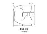
全体が参照により本明細書に組込まれているGarinoに対する特許文献1(米国特許出願公開第2017/0252173号明細書)中に記載されている通り、全ての用途のために、人工膝は、概して、3つの主要な構成要素、すなわち大腿骨の遠位端部に取付けられる大腿骨構成要素(図1Aおよび1B)、脛骨の近位端部上に移植される脛骨構成要素(図2Aおよび2B)、および脛骨構成要素上に組付けられ大腿骨構成要素のための摩擦表面を提供する関節挿入物(図3Aおよび3B)を含む。構成要素は、関節および、膝の可動域全体にわたり人間の膝の付随する力学をシミュレートするように設計される。構成要素は概して、変動する寸法(図1A〜3Bにおいて寸法A−HおよびJ−Tとして識別)を有する多様な形状で提供されており、こうして、医師は、患者の特異的生体構造に応じて構成要素の最適な組合せを選択できるようになっている。膝のサイズおよび形状は、患者の年令、性別およびサイズを含めたさまざまな要因に左右される。したがって、患者に合わせて人工膝を調整できるように、一般にかなり幅広い構成要素の在庫が入手可能になっている。 For all uses, artificial knees are generally used, as described in Patent Document 1 for Garino (US Patent Application Publication No. 2017/0252173), which is incorporated herein by reference in its entirety. Three major components, the femur component attached to the distal end of the femur (FIGS. 1A and 1B), the tibial component implanted on the proximal end of the tibia (FIGS. 2A and 2B). , And joint inserts (FIGS. 3A and 3B) that are assembled onto the tibial component and provide a friction surface for the femoral component. The components are designed to simulate the associated dynamics of the human knee over the range of motion of the joint and knee. The components are generally provided in a variety of shapes with varying dimensions (identified as dimensions AH and JT in FIGS. 1A-3B), thus allowing the physician to respond to the patient's specific biostructure. The optimum combination of components can be selected. The size and shape of the knee depends on a variety of factors, including the patient's age, gender and size. Therefore, a fairly wide inventory of components is generally available so that the knee can be tailored to the patient.
TKRの場合の通常の膝構築の間、ACLは、全事例の大部分において除去され、選択されたTKR設計に応じて、患者のPCLは保持されるか、またはPCLの失なわれた機能を代用するよう何らかの機構で置換される。PCLが保持される場合でも、多くの場合、膝置換の平衡化を補助するため、外科手術中にPCLの一部分を切断するかまたは部分切断しなければならない。PCLが完全に除去される場合、PCLはポストおよびカム機構によって代用される。 During normal knee construction in the case of TKR, ACL is removed in most of all cases, and depending on the TKR design selected, the patient's PCL is retained or the PCL's lost function is retained. It is replaced by some mechanism to substitute. Even if the PCL is retained, it is often necessary to amputate or partially amputate the PCL during surgery to aid in equilibration of the knee replacement. If the PCL is completely removed, the PCL is replaced by a post and cam mechanism.
TKRは概して、大腿骨構成要素10、脛骨構成要素16および大腿骨構成要素10と相互作用するため脛骨構成要素16の上部組付け用部分20上に存在する関節挿入物22を含む。図1A、1B、3Aおよび3Bを参照すると、ポストおよびカム機構の典型的設計の例示が提供されている。関節挿入物22は、大腿骨構成要素10の開口部12内に突き出す延長部分24を含む。上向きに突出する壁を有するボックス11が、大腿骨構成要素10の内部側に形成され、開口部12と交差する内部領域を含む。延長部分24は、関節が屈曲されたときに開口部12の後部表面14と摩擦接触状態となるように意図された後部表面25を含む。延長部分24が大腿骨構成要素10内の開口部12の後部表面14に接して担持されている場合に生成される抵抗は、健康な後十字靭帯(PCL)によって生じるはずの抵抗をシミュレートするように意図されている。 The TKR generally includes a
延長部分24の前部表面と開口部12の前部表面の間にカム表面を創出することによって、ACLの機能を部分的に置換するカムおよびポストの機構が製造されてきた。しかしながら、この解決法は、延長部分24の前部側がせいぜい0〜20度の屈曲の場合にしか開口部の前部側と接触できないことから、ACLの部分的な代用しか提供しない。 Cam and post mechanisms have been manufactured that partially replace the function of the ACL by creating a cam surface between the front surface of the
別の解決法は、参照により本明細書にその内容が組込まれている特許文献2(米国特許第5,935,133号明細書)中で開示されている材料などのケーブル様の材料で大腿骨構成要素および脛骨構成要素を連結することにある。しかし、この人工的材料は典型的には、PCLを置換するためにのみ使用され、ACLを置換するためには使用されない。 Another solution is a femur with a cable-like material, such as the material disclosed in Patent Document 2 (US Pat. No. 5,935,133), the contents of which are incorporated herein by reference. To connect the bone and tibial components. However, this artificial material is typically used only to replace the PCL, not to replace the ACL.
解剖学的に適正な置換が欠如していることから、もとの膝に比べると機能性が低いTKRが結果としてもたらされる可能性がある。このことは、外科手術後の理学療法中に支障を発生させ、かつ療法後に身体活動に参加する患者の能力または願望を制限する可能性がある。現代のほぼ全ての全膝置換術は、ACLを犠牲にするか、または膝関節を未熟なカムおよびポスト機構で不適切に代用するため、再建された膝にはACL不全の膝のものに類似する運動機能しか残されない。したがって、正常な膝の運動機能は、なお捉え難いものであり続けている。さらに、ACLとPCL(これらは共に正常な膝の運動学を駆動するものである)の間の適正な相互作用が欠如しているため、TKR再建は、患者にとって比較的正常である膝を作り出す域に達していない状態にとどまっている。 The lack of proper anatomical replacement can result in a less functional TKR than the original knee. This can cause disability during post-surgical physiotherapy and limit the patient's ability or desire to participate in physical activity after surgery. Almost all modern knee replacements sacrifice ACL or improperly replace the knee joint with an immature cam and post mechanism, so the reconstructed knee resembles that of an ACL-deficient knee. Only the motor function to do is left. Therefore, normal knee motor function remains elusive. In addition, TKR reconstruction produces a knee that is relatively normal for the patient, due to the lack of proper interaction between ACL and PCL, both of which drive normal knee kinematics. It remains in a state where it has not reached the range.
膝関節の力学の複雑性および患者が外科手術後に人工膝に順応することの難しさのため、以前は除去された靭帯によって提供されていた復元力および支持をより正確にシミュレートする解剖学的に適正な膝置換システムが必要とされている。解剖学的に、より適正なTKRを提供する目的で、ACLおよびPCLの両方により提供される機能を再現するプロテーゼの実施形態が所望される。 Anatomy that more accurately simulates the resilience and support previously provided by the removed ligaments due to the mechanical complexity of the knee joint and the difficulty of the patient adapting to the total knee after surgery A proper knee replacement system is needed. An embodiment of a prosthesis that reproduces the functions provided by both ACLs and PCLs is desired for the purpose of providing anatomically more relevant TKR.
ここで図4を参照すると、元来の解剖学上のACLおよびPCLの場所の上に例示的な人工ACL/PCL靭帯を表わすループ30が描画された状態で、健康な人間の膝が例示されている。ループ30の人工PCLを構成する区分は、点26Aおよび26Bによって境界が示されている。ループ30の人工ACLを構成する区分は、点28Aおよび28Bによって境界が示されている。 Referring now to FIG. 4, a healthy human knee is illustrated with a loop 30 representing an exemplary artificial ACL / PCL ligament drawn above the original anatomical ACL and PCL locations. ing. The sections that make up the artificial PCL of loop 30 are bounded by points 26A and 26B. The sections that make up the artificial ACL of loop 30 are bounded by points 28A and 28B.
ここで、Garinoに対する特許文献1中に開示されている実施形態を例示する図5、6Aおよび6Bによると、靭帯44として提供されている人工的材料の連結点26a、26b、28aおよび28bおよび人工靭帯44の輪郭として提供されている連結点間にまたがる長さは、図4に例示されている人間の膝内のACLおよびPCLの寸法および付着点をシミュレートするように構成されている。TKRの大腿骨構成要素10と関節挿入物22を連結するために、少なくとも1つの一定長の人工靭帯を提供することができる。 Here, according to FIGS. 5, 6A and 6B illustrating embodiments disclosed in Patent Document 1 to Garino, the
Garinoに対する特許文献1は、これらの複雑性に対する解決法を提供するものの、膝関節の力学を改善するために、この分野における開発は絶えず求められている。 Although Patent Document 1 to Garino provides a solution to these complications, development in this area is constantly being sought in order to improve the mechanics of the knee joint.
本発明の一実施形態によると、膝関節プロテーゼは、伸展位置と屈曲位置の間を移動する能力を有する。膝関節プロテーゼは、大腿骨に組付けられるように構成された大腿骨構成要素と、脛骨に組付けられるように構成された脛骨構成要素であって、大腿骨構成要素と係合させられて膝関節プロテーゼを形成するように構成された脛骨構成要素とを含む。第1のポストが、大腿骨構成要素および脛骨構成要素のうちの一方に固定的に連結された、膝関節プロテーゼの伸展位置または屈曲位置のいずれかにおいて第1のポストにより係合されるように構成された第1のカム陥凹が、大腿骨構成要素および脛骨構成要素のうちの他方の上に画定されている。第2のポストが、大腿骨構成要素および脛骨構成要素のうちの一方に対して固定的に連結され、膝関節プロテーゼの伸展位置または屈曲位置のいずれかにおいて第2のポストにより係合されるように構成された第2のカム陥凹が、大腿骨構成要素および脛骨構成要素のうちの他方の上に画定されている。 According to one embodiment of the invention, the knee prosthesis has the ability to move between extended and flexed positions. The knee prosthesis is a femoral component configured to be assembled to the femur and a tibial component configured to be assembled to the tibia, which is engaged with the femur component to the knee. Includes tibial components configured to form a joint prosthesis. The first post is engaged by the first post at either the extension or flexion position of the knee prosthesis, which is fixedly connected to one of the femoral and tibial components. A constructed first cam recess is defined above the other of the femoral and tibial components. The second post is fixedly connected to one of the femoral and tibial components so that it is engaged by the second post in either the extension or flexion position of the knee prosthesis. A second cam recess constructed in is defined above the other of the femoral and tibial components.
本発明の別の実施形態において、膝関節プロテーゼは、大腿骨に組付けられるように構成された大腿骨構成要素と、脛骨に組付けられるように構成された脛骨構成要素であって、大腿骨構成要素と係合させられて膝関節プロテーゼを形成するように構成された脛骨構成要素とを含む。ポストが、大腿骨構成要素および脛骨構成要素のうちの一方に固定的に連結されており、カム陥凹が、大腿骨構成要素および脛骨構成要素のうちの他方の上に画定され、膝関節プロテーゼの伸展位置または屈曲位置のいずれかにおいて第1のポストにより係合されるように構成されている。人工靭帯が、大腿骨構成要素および脛骨構成要素に対して固定的に連結されて、前十字靭帯または後十字靭帯のいずれかをシミュレートする。ポストおよび靭帯は、矢状面、前頭面または矢状面および前頭面の両方で見た場合、交差するように配向されている。 In another embodiment of the invention, the knee prosthesis is a femoral component configured to be assembled to the femur and a tibial component configured to be assembled to the tibia, the femur. Includes a tibial component configured to engage with the component to form a femoral prosthesis. The post is fixedly connected to one of the femoral and tibial components, the cam recess is defined over the other of the femoral and tibial components, and the knee prosthesis. It is configured to be engaged by the first post at either the extension position or the flexion position of the. The artificial ligament is fixedly connected to the femoral and tibial components to simulate either the anterior cruciate ligament or the posterior cruciate ligament. The posts and ligaments are oriented to intersect when viewed in both the sagittal, frontal or sagittal and frontal planes.
本発明のさらに別の実施形態において、膝関節プロテーゼは、大腿骨に組付けられるように構成された大腿骨構成要素と、脛骨に組付けられるように構成された脛骨構成要素を含む。脛骨構成要素は、大腿骨構成要素と係合して膝関節プロテーゼを形成するように構成されている。大腿骨構成要素および脛骨構成要素は少なくとも部分的に、歯車付き配設によって共に連結されている。 In yet another embodiment of the invention, the knee prosthesis comprises a femoral component configured to be assembled to the femur and a tibial component configured to be assembled to the tibia. The tibial component is configured to engage the femoral component to form a knee prosthesis. The femoral and tibial components are connected together, at least in part, by a geared arrangement.
図面は次の通りである:
本発明は、膝関節プロテーゼのさまざまな実施形態を提供する。図中、「A」は、前部側または方向を表わし、「P」は後部側または方向を表わし、「M」は内側側または方向を表わし、関節挿入物は外側側または方向を表わし、「F」は大腿骨構成要素を表わし、「T」は脛骨構成要素(または脛骨構成要素の一部を成す関節挿入物)を表わす。 The present invention provides various embodiments of a knee prosthesis. In the figure, "A" represents the anterior side or direction, "P" represents the posterior side or direction, "M" represents the medial side or direction, the joint insert represents the lateral side or direction, and " "F" represents a femoral component and "T" represents a tibial component (or a joint insert that forms part of a tibial component).
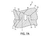
図7Aは、膝関節プロテーゼ100が伸展位置で示されている、本発明の例示的実施形態に係る、矢状面で見た膝関節プロテーゼ100の断面側面立面図である。図7Bは、膝関節プロテーゼ100が屈曲位置で示されている、図7Aの膝関節プロテーゼ100の別の図である。膝関節プロテーゼ100は、図7Aの伸展位置と図7Bの屈曲位置の間で回転する能力を有する。 FIG. 7A is a cross-sectional side elevation view of the
プロテーゼ100は概して、大腿骨構成要素102および脛骨構成要素に対し組付けられているかまたはこの脛骨構成要素の一部を成す関節挿入物104を含む。 The
図7Aおよび7Bに示されている大腿骨構成要素102は、顆状突起を有する大腿骨構成要素(アイテム10のような)または大腿骨構成要素に組付けられたボックス(ボックス11のような)を表わし得る。大腿骨構成要素102の下端部には陥凹108が形成されている。陥凹108は、内側−外側方向に沿って顆状突起106の間に位置設定されている。陥凹108が大腿骨構成要素102の外部表面と交差する場所で、陥凹108の半円形境界において縁部111が形成される。陥凹108は、大腿骨構成要素10内の開口部12と同じ近似場所に位置付けされる。しかしながら開口部12とは異なり、陥凹108は盲であり、平滑で丸味のある内部表面を含む。2つのカム表面110aおよび110b(個別にかまたは集合的にカム表面110と呼ばれる)は、陥凹108の内部表面の相対する端部に形成されている。各カム110は、平滑で丸味のある凹状表面である。カム110の半径は、同じであっても異なっていてもよい。カム110は、関節挿入物104の上部表面から延在する丸みのあるポスト112aおよび112bと相互作用するように構成されている。 The
関節挿入物104は、関節挿入物22に類似したものであり、これらの挿入物の間の主な差異について以下で説明する。関節挿入物104は、担持表面113から延在する2つのポスト112aおよび112b(個別的にかまたは集合的にポスト表面112と呼ばれる)を含む。ポスト112aはACLに対応し、一方、ポスト112bはPCLに対応する。各々の丸味のあるポスト112は、凸状に丸められた表面で終結する。各ポスト112の半径は、各カム110の半径と同一であっても実質的に同じであってもよい。ポスト112の延長部分の高さおよび半径は、噛合するカム110の幾何形状を補完するため、異なるものであっても(図示通り)、同じものであってもよい。この実施形態によると、ACLポスト112aは、PCLポスト112bよりも大きい高さを有する。ポスト112は、担持表面113に直交するそれぞれの軸Zに沿って延在する。代替的には、ポスト112は、軸Zとの関係において斜めに延在し得る。図7Aのポスト112ならびに本明細書中に記載の他の全てのポストは、図示されている通り、関節挿入物22(またはポストが連結されている他の構成要素)と一体になっているか、または機械的ネジ山、ボルト、摩擦、接着剤、セメントまたは、当業者にとって公知である2つの構成要素を共に組付けるための他の任意の手段を用いて、関節挿入物22に連結されていてよい。 The
関節挿入物104は、図7Aの伸展位置と図7Bの屈曲位置の間で大腿骨構成要素102との関係において回転する能力を有する。膝関節プロテーゼ100の伸展位置において、顆状突起は関節挿入物104の担持表面113上に載っていてよく、ポスト112はそのそれぞれのカム110と接して位置付けされる。大腿骨構成要素102が関節挿入物104に対してまたはその逆に回転するにつれて、ポスト112は、陥凹108の縁部111が後部ポスト112の基礎に担持されるまで、カム110の表面に沿って進む。ACLポスト112aは、そのカム110a上に担持されてよい。図示されてはいないものの、膝関節プロテーゼ100に隣接する側副靭帯(MCLおよびLCL)は、関節挿入物104から大腿骨構成要素102が脱出するのを防止している。 The
2つのポスト112および2つのカム110を配設することにより、単一のポストと単一のカムを有する従来の膝関節プロテーゼと比べて、PCLおよびACLの配設がより密に模倣される。 By disposing the two posts 112 and the two cams 110, the arrangement of the PCL and ACL is more closely mimicked as compared to a conventional knee prosthesis with a single post and a single cam.
上述の通り、陥凹108は、ボックス11と同様に、大腿骨構成要素102に対して取付けることのできる別個の挿入物の中に形成されてよい。異なる陥凹幾何形状を有する一連の挿入物がキットとして提供され得、こうして、患者の特定の生体構造に最も適合した幾何形状を有する挿入物を医療専門家が選択できるようになっている。 As mentioned above, the
図8は、ポスト122aおよび122bが大腿骨構成要素124上に配置され、カム128が脛骨構成要素の関節挿入物132上に配置された陥凹130上に画定されている、膝関節プロテーゼ118を描いている。膝関節プロテーゼ118は、ポストとカムの場所が交換されている点を除いて、膝関節プロテーゼ100と類似している。膝関節プロテーゼ118の動作は、膝関節プロテーゼ100の動作と実質的に類似している。図示されてはいないものの、ポスト122aおよび122bは、ボックス11と同様に、大腿骨構成要素124に取付けることのできる別個の挿入物の中に形成され得る。 FIG. 8 shows the
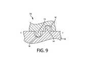
図9は、膝関節プロテーゼ136を描いている。膝関節プロテーゼ136は、1つのポスト138および1つのカム陥凹140が大腿骨構成要素142上に配置され、1つのポスト144および1つのカム陥凹146が脛骨構成要素の関節挿入物148上に配置されているという点を除いて、膝関節プロテーゼ100と類似している。図9に示された伸展位置において、大腿骨構成要素142のポスト138は、脛骨関節挿入物148のカム陥凹146と共に組付けられ、脛骨関節挿入物148のポスト144は、大腿骨構成要素142のカム陥凹140と共に組付けられている。ポスト138は陥凹140の前方に配置されているが、ポスト138および陥凹140の場所を(陥凹146およびポスト144の場所と共に)交換することができるということを理解すべきである。膝関節プロテーゼ136の動作は、膝関節プロテーゼ100の動作と実質的に類似している。 FIG. 9 depicts a
図10Aおよび10Bは、膝関節プロテーゼ150の部分断面図の一実施形態を描いている。プロテーゼ150はプロテーゼ100と類似しており、その間の主な差異についてのみ説明する。膝関節プロテーゼ150において、それぞれPCLおよびACLをより密に模倣するポスト152aおよび152b(集合的にポスト152と呼ばれる)は、脛骨部分の関節挿入物154(または脛骨部分自体)の上に配置され、大腿骨構成要素158上に形成されている陥凹157上に配置されたカム156aおよび156b(集合的にカム156と呼ばれる)とそれぞれ係合する。陥凹157は、プロテーゼ150の担持表面155から上向きに延在する。 10A and 10B depict an embodiment of a partial cross-sectional view of the
具体的には、関節挿入物154の外側および後部側から大腿骨構成要素158の内側および前部側まで延在するポスト152aは、PCLの場所および幾何形状をより密に模倣する。関節挿入物154の内側および前部側から大腿骨構成要素158の外側および後部側まで延在するポスト152bは、ACLの場所および幾何形状をより密に模倣する。ポスト152aおよび152bは、矢状面で見た場合および前頭面内で見た場合に交差するように配向されているが、ポスト152aおよび152bを、これらの平面のうちの一方において見た場合にのみ交差するように配向することもできる。 Specifically, the
矢状面内で見た場合の担持表面155との関係における各ポスト152の角度「B」は、図示されているものから変動してよく、ACLまたはPCLの正確な角度を近似するように調整され得る。同様にして、前頭面で見た場合の関節挿入物154の担持表面155との関係における各ポスト152の角度「D」は、図示されているものから変動していてよく、ACLまたはPCLの正確な角度を近似するように調整され得る。角度BおよびDは、図中では誇張されている可能性があることが指摘される。各ポスト152の長さおよび直径は、図示されているものから変動してよく、ACLまたはPCLのものを近似するように調整され得る。各ポスト152は必ずしも、図示されているように長手方向軸に沿って真直ぐに延在している必要はなく、代って、ACLまたはPCLの曲線形状を近似するように湾曲していてよい。 The angle "B" of each post 152 in relation to the supported
各ポスト152は、陥凹157のカム156の凹状表面と回転可能かつ摺動可能な形で係合する凸状の丸味のある表面を含む。ポスト152およびカム156は摺動接触状態にあるが、物理的に互いに分離していることが指摘される。図示されてはいないものの、陥凹157は、大腿骨構成要素158に対して取外し可能な形で取付けられるボックス11のような別個の挿入物の中に形成されてよい。 Each post 152 includes a convex rounded surface that rotatably and slidably engages the concave surface of the cam 156 of the
図11は、ポスト159aおよび159bが大腿骨構成要素162上に配置され、脛骨部分の関節挿入物165(または脛骨部分自体)の上に形成されている陥凹163上に配置されたカム161aおよび161bとそれぞれに係合している、という点を除いて膝関節プロテーゼ150と類似である膝関節プロテーゼ160の変形実施形態を描いている。ポストとカムの場所は互換性があるが、ポスト159aおよび159bの場所および幾何形状は、それぞれACLおよびPCLのものを模倣し続けるという点が指摘される。同様に、図9に示された実施形態と同様、図示されてはいないものの、関節挿入物165および大腿骨構成要素162の各々は、1つの角度付きポストおよび1つのカムを含んでいてよい。 FIG. 11 shows a
図12は、膝関節プロテーゼ180の一変形実施形態を描いている。膝関節プロテーゼ180は、膝関節プロテーゼ150と類似しており、以下では、主な差異について説明する。膝関節プロテーゼ180において、PCLを模倣するポスト182は、脛骨部分184の上に配置され、大腿骨部分188上のカム陥凹186と係合する。ACLを模倣する人工靭帯190は、脛骨部分184および大腿骨部分188に固定されている。固定は、図12中、小文字「xxx」で示されている。 FIG. 12 depicts a modified embodiment of the
ポスト182は、関節挿入物184の外側および後部側から大腿骨構成要素188の内側および前部側まで延在して、PCLの場所を模倣する。靭帯190は、関節挿入物184の内側および前部側から大腿骨構成要素188の外側および後部側まで延在して、ACLの場所を模倣する。靭帯190は、ポスト182と異なり、関節挿入物184および大腿骨構成要素188の両方に固定的に連結される。ポスト182および靭帯190は、矢状面見た場合および前頭面で見た場合交差するように配向されているが、ポスト182および靭帯190を、これらの平面のうちの一つで見た場合にのみ交差するように配向することもできる。 The
図13は、靭帯190’およびポスト182’の場所が交換されこうして靭帯190’がPCLを表わしポスト182’がACLを表わすようになっているという点を除いてプロテーゼ180に類似するものである膝関節プロテーゼ192の変形実施形態を描いている。図12および13に代わるものとして、患者の自然のACLまたはPCLが部分膝置換術において保存される場合、ポスト182を完全に削除することができる。 FIG. 13 is similar to the
本明細書中に示されている靭帯は、ACLまたはPCLに置換するため、人工材料、好ましくは合成繊維または撚糸から形成されており、したがって人工材料は正常な膝の中のACLおよびPCLのそれぞれの配向および場所と同様の形で構成されている。具体的には、構成は、TKR内の人工材料の原点および挿入点が正常な膝内のACLおよびPCLの原点および挿入点に類似することになるようなものである。 The ligaments shown herein are made of artificial materials, preferably synthetic fibers or twisted yarns to replace ACLs or PCLs, thus the artificial materials are ACLs and PCLs in a normal knee, respectively. It is composed in the same shape as the orientation and location of. Specifically, the configuration is such that the origin and insertion point of the artificial material in the TKR will be similar to the origin and insertion point of the ACL and PCL in the normal knee.
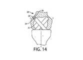
図14は、PCLポスト202の自由端部が機械的ネジ山であり得る螺旋状突出部204を含むという点を除いて膝関節プロテーゼ150と類似のものである膝関節プロテーゼ200の変形実施形態を描いている。螺旋状突出部204を収容する大腿骨構成要素内のカム206は、螺旋状陥凹208を含む。螺旋状陥凹208は、螺旋状突出部204と相互作用して、膝関節プロテーゼ200が伸展位置と屈曲位置の間を移動するにつれて軸Yを中心としたわずかな回転をひき起こす。わずかな回転は、完全に伸展した状態になったときに実際の膝関節内において感じられるわずかな回転を模倣する。螺旋表面204および208は、代替的には、くさび形、角度付きまたは勾配付き表面の形で提供され得る。 FIG. 14 shows a modified embodiment of the
「人工的」なる用語は、TKR前の原初の形態での原初の解剖学的ACLまたはPCL靭帯ではないことのみを意味し、合成材料のみの使用に対する限定として解釈されるべきではない。したがって、人工靭帯は、生物学的に創出された材料から作り出された材料などの「天然」材料を含むことができ、かつ/または、合成材料と天然材料のハイブリッドを含むことができる。他の例示的材料には、後脊髄再建における外科的固定のために使用される編組超高分子量ポリエチレン(UHMWPE)ケーブルであるSecure Strand(登録商標)ケーブルとして以前市販されていた材料に類似する製織ポリエチレンの変形形態、UHMWPEおよびNylon6/6.6から作られたSuper Cables(登録商標)(Kinamed,Inc.,Camarillo,CA)として現在市販されている材料、Gore−tex(登録商標)(W.L.Gore and Associates,Inc.Newark,DE,が製造するPTFE繊維)、炭素繊維、または他の類似の製織材料が含まれ得る。 The term "artificial" only means that it is not the primordial anatomical ACL or PCL ligament in its primordial form before TKR and should not be construed as a limitation on the use of synthetic materials alone. Thus, artificial ligaments can include "natural" materials, such as materials created from biologically created materials, and / or hybrids of synthetic and natural materials. Other exemplary materials include weaving similar to materials previously marketed as Secure Strand® cables, which are braided ultra-high molecular weight polyethylene (UHMWPE) cables used for surgical fixation in posterior spinal cord reconstruction. A variant of polyethylene, Gore-tex® (W. PTFE fibers produced by L. Gore and Associates, Inc. Newark, DE,), carbon fibers, or other similar weaving materials may be included.
本発明のさまざまな実施形態によると、例えば人工靭帯の形での人工材料は、外科手術の時点でTKR内に取込むことができ、または外科手術に先立ってTKRを人工材料と予め組立てることができる。靭帯を脛骨構成要素および大腿骨構成要素に連結するためのさまざまな方法およびデバイスが、Garinoに対する米国特許出願公開第2017/0252173号中に記載されている。この参考文献中で記載されているように、人工靭帯の端部用の係止機構は、いずれかの特定の構成に限定されず、球形リテイナ、金属クリップ、フック、ループ、爪の形をした締結具などを含み得る。 According to various embodiments of the invention, the artificial material, for example in the form of artificial ligaments, can be incorporated into the TKR at the time of surgery, or the TKR can be preassembled with the artificial material prior to surgery. it can. Various methods and devices for connecting ligaments to tibial and femoral components are described in US Patent Application Publication No. 2017/0252173 to Garino. As described in this reference, the locking mechanism for the ends of artificial ligaments is not limited to any particular configuration, but is in the form of spherical retainers, metal clips, hooks, loops, claws. It may include fasteners and the like.
上述の実施形態を考慮して、ポスト、カムおよび靭帯を異なる構成要素に対し異なる場所に連結することができる、ということを認識すべきである。したがって、上述の実施形態は、限定的なものとしてみなされるべきではない。 It should be recognized that the posts, cams and ligaments can be connected in different places to different components in view of the above embodiments. Therefore, the above embodiments should not be considered as limiting.
図15Aおよび15Bは、脛骨部分302が大腿骨部分304に対してラックアンドピニオンタイプの歯車付き配設によって結合されている、矢状面内で見た場合の膝関節プロテーゼ300の変形実施形態の側面立面図を描いている。図15Aおよび15Bに示された膝関節プロテーゼ300の部分は、膝関節プロテーゼ全体を表わしていないということを理解すべきである。むしろ、図15Aおよび15Bに示された膝関節プロテーゼ300の部分は、脛骨部分302および大腿骨部分304の、ボックス(ボックス11のような)の部域内で互いに接触する部分を表わす。膝関節プロテーゼ300は、図15A中では伸展位置で示され、図15B中では屈曲位置で示されている。脛骨部分302上の歯306は、大腿骨部分304の歯308と噛合し、こうして脛骨部分302の回転は大腿骨部分304の回転をひき起こし、逆も同様となる。 15A and 15B show a modified embodiment of the
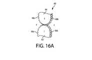
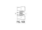
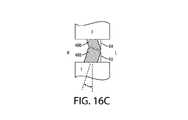
図16A〜16Cは、脛骨部分402が歯車付き配設によって大腿骨部分404に結合される、膝関節プロテーゼ400の変形実施形態を描いている。膝関節プロテーゼ400は膝関節プロテーゼ300と実質的に類似しており、これらの実施形態間の主な差異について以下で説明する。 16A-16C depict a modified embodiment of the
脛骨部分402は、上に歯406が配置されている丸味のある凸状外部表面を含む。凸状外部表面は、円弧をたどる単純曲線経路を有する後部セグメント406aおよび螺旋経路をたどる前部セグメント406bを含む。螺旋経路は、前部方向で見た場合、内側に延在する。歯も同様に、前部セグメント406bの螺旋経路の軌道をたどる。後部セグメント406aは段階的に前部セグメント406bと交差する。 The
同様にして、大腿骨部分404は、上に歯408が配置されている凸状外部表面を含む。凸状外部表面は、円弧をたどる単純曲線経路を有する後部セグメント408aおよび螺旋経路をたどる前部セグメント408bを含む。螺旋経路は、前部方向で見た場合、内側に延在する。歯も同様に、前部セグメント408bの螺旋経路の軌道をたどるということを理解すべきである。後部セグメント408aは段階的に前部セグメント406bと交差する。 Similarly, the
後部セグメント408aおよび前部セグメント408bは両方共螺旋軌道をたどるものとして図示され説明されているが、これらのセグメントの1つのみが螺旋軌道をたどることもできる。 Although both the
脛骨部分402上の歯406は、大腿骨部分404の歯408と噛合しており、こうして、脛骨部分402の回転が大腿骨部分404の回転をひき起こし、その逆も同様となる。同様に、脛骨部分402が前部方向に向かって伸展位置まで回転するにつれて、脛骨部分402も同様に内側方向に移動する。脛骨部分402の内側方向へのわずかな回転は、完全に伸展した状態になったときに実際の膝関節内において感じられるわずかな回転を模倣する。内側方向への回転は、噛合する前部部分406bおよび408bの螺旋状幾何形状に起因する。 The teeth 406 on the
図17は、ポスト502およびカム504の配設によって脛骨部分が大腿骨部分に結合されている、矢状面内で見た場合の膝関節プロテーゼ500の変形実施形態を描いている。膝関節プロテーゼ500は、歯306および308がそれぞれポスト502およびカム504によって置換されている点を除き、膝関節プロテーゼ300と実質的に類似するものである。膝関節プロテーゼ300の歯406および408を、膝関節プロテーゼ500のポストカム配設のようなポストカム配設により同様に置換し得るということを理解すべきである。 FIG. 17 depicts a modified embodiment of the
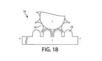
図18に示されているように、ポスト506およびカム508の配置を、本発明の範囲または精神から逸脱することなく交換することができる。 As shown in FIG. 18, the arrangement of
図19は、脛骨部分Tがピン602およびスロット604の配設によって大腿骨部分Fに結合されている膝関節プロテーゼ600の変形実施形態を描く平面図である。膝関節プロテーゼ600は、図19では屈曲位置で示されている。他の実施形態と同様に、図19に示されている膝関節プロテーゼ600の部分は、膝関節プロテーゼ全体ではなく脛骨部分Tおよび大腿骨部分Fの、ボックス(ボックス11のような)の部域内で互いに接触する部分を表わしているにすぎない。 FIG. 19 is a plan view depicting a modified embodiment of the knee
この実施形態によると、ピン602は、大腿骨部分F上に配置され、スロット604は脛骨構成要素T上に配置されているが、逆も当てはまり得ると考えられる。ピン602は、スロット604の深さ内へ垂直方向に延在する。動作中、ピン602はスロット604の長さに沿って進む。スロット604は、前部方向で見た場合、内側方向に湾曲する。 According to this embodiment, the
動作中、脛骨部分Tが前部方向に伸展位置まで回転し、ピン602がスロット604の長さに沿って進むにつれて、脛骨部分Tは同様に内側方向に回転する。内側方向での脛骨部分Tのわずかな回転は、完全に伸展した状態になったときに実際の膝関節内において感じられるわずかな回転を模倣する。内側方向の運動は、スロット604の曲率に起因する。 During operation, the tibial portion T rotates anteriorly to the extended position, and as the
膝関節プロテーゼの構成要素は、同じまたは類似の材料で製造され得る。しかしながら、一般的には、全ての材料は好ましくは不活性で、感染をひき起こす傾向がなく、かつ外科用移植片としての使用のために認可された、他の点では安全なものである。例示的材料としては、ポリエチレン、外科的に認可された金属合金、外科的に認可されたセラミック材料、またはそれらの組合せが含まれる。外科用移植片の分野における任意の周知の材料を用いて、本発明に係るさまざまな実施形態またはその一部分のいずれかを製造することができる。 The components of the knee prosthesis can be made of the same or similar materials. However, in general, all materials are preferably inert, do not tend to cause infection, and are otherwise approved for use as surgical implants and are otherwise safe. Illustrative materials include polyethylene, surgically approved metal alloys, surgically approved ceramic materials, or combinations thereof. Any well-known material in the field of surgical implants can be used to produce any of the various embodiments of the invention or parts thereof.
本明細書では、本発明の好ましい実施形態が図示され説明されてきたが、このような実施形態は一例として提供されているにすぎないということを理解すべきである。当業者であれば、本発明の精神から逸脱することなく多くの変形形態、変更および代用を思い付く可能性がある。したがって、添付のクレームは、本発明の精神および範囲内に入る全てのこのような変形形態を網羅する、ということが意図されている。 Although preferred embodiments of the present invention have been illustrated and described herein, it should be understood that such embodiments are provided by way of example only. One of ordinary skill in the art may come up with many variants, modifications and substitutions without departing from the spirit of the invention. Accordingly, the accompanying claims are intended to cover all such variants that fall within the spirit and scope of the invention.
10 大腿骨構成要素
12 開口部
16 脛骨構成要素
20 上部組付け用部分
22 関節挿入物
24 延長部分
25 後部表面
30 ループ
44、190 靭帯
100、118、150、192、200、3000、400、500 膝関節プロテーゼ
102、124、142、150、158、162、188 大腿骨構成要素
104、132、148、154 関節挿入物
106 顆状突起
108、130、140、146、157、163 陥凹
110、128、156、504、508 カム
111 縁部
112、122、138、144、152、182、502、506 ポスト
113、155 担持表面10
Claims (22)
Translated fromJapanese大腿骨に組付けられるように構成された大腿骨構成要素と;
脛骨に組付けられ前記大腿骨構成要素と係合して前記膝関節プロテーゼを形成するように構成された脛骨構成要素と;
前記大腿骨構成要素および前記脛骨構成要素のうちの一方に固定的に連結された第1のポスト、および前記大腿骨構成要素および前記脛骨構成要素のうちの他方の上に画定され、前記膝関節プロテーゼの前記伸展位置または前記屈曲位置のいずれかにおいて前記第1のポストと係合するように構成された第1のカム陥凹と;
前記大腿骨構成要素および前記脛骨構成要素のうちの一方に対して固定的に連結された第2のポスト、および前記大腿骨構成要素および前記脛骨構成要素のうちの他方の上に画定され、前記膝関節プロテーゼの前記伸展位置または前記屈曲位置のいずれかにおいて前記第2のポストと係合するように構成された第2のカム陥凹と;
を含む膝関節プロテーゼ。In a knee prosthesis configured to move between extension and flexion positions
With femur components configured to be assembled to the femur;
With a tibial component that is assembled to the tibia and is configured to engage with the femoral component to form the knee prosthesis;
A first post fixedly connected to one of the femoral component and the tibial component, and the knee joint defined on the other of the femur component and the tibial component. With a first cam recess configured to engage the first post at either the extension position or the flexion position of the prosthesis;
A second post fixedly connected to one of the femoral component and the tibial component, and defined on the other of the femur component and the tibial component, said. With a second cam recess configured to engage the second post at either the extension position or the flexion position of the femoral prosthesis;
Knee prosthesis including.
大腿骨に組付けられるように構成された大腿骨構成要素と;
脛骨に組付けられるように構成された脛骨構成要素であって、前記大腿骨構成要素と係合して前記膝関節プロテーゼを形成するように構成された脛骨構成要素と;
前記大腿骨構成要素および前記脛骨構成要素のうちの一方に固定的に連結されたポスト、および前記大腿骨構成要素および前記脛骨構成要素のうちの他方の上に画定され、前記膝関節プロテーゼの前記伸展位置または前記屈曲位置のいずれかにおいて前記ポストと係合するように構成されたカム陥凹と;
前記大腿骨構成要素および前記脛骨構成要素に対して固定的に連結されて、前十字靭帯または後十字靭帯のいずれかをシミュレートする人工靭帯と;
を含み、
前記ポストおよび前記靭帯が、矢状面、前頭面または前記矢状面および前記前頭面の両方で見た場合、交差するように配向されている、
膝関節プロテーゼ。In a knee prosthesis configured to move between extension and flexion positions
With femur components configured to be assembled to the femur;
With a tibial component configured to be assembled to the tibia, which is configured to engage with the femur component to form the knee joint prosthesis;
The post fixedly connected to one of the femoral component and the tibial component, and the above-mentioned knee joint prosthesis defined on the other of the femoral component and the tibial component. With a cam recess configured to engage the post in either the extension position or the flexion position;
With an artificial ligament that is fixedly connected to the femoral component and the tibial component to simulate either the anterior cruciate ligament or the posterior cruciate ligament;
Including
The posts and ligaments are oriented to intersect when viewed in both the sagittal, frontal or sagittal and frontal planes.
Knee prosthesis.
大腿骨に組付けられるように構成された大腿骨構成要素と;
脛骨に組付けられるように構成された脛骨構成要素であって、前記大腿骨構成要素と係合して前記膝関節プロテーゼを形成するように構成された脛骨構成要素と;
を含み、
前記大腿骨構成要素および前記脛骨構成要素が少なくとも部分的に、歯車付き配設によって共に連結されている、膝関節プロテーゼ。In a knee prosthesis configured to move between extension and flexion positions
With femur components configured to be assembled to the femur;
With a tibial component configured to be assembled to the tibia, which is configured to engage with the femur component to form the knee joint prosthesis;
Including
A knee prosthesis in which the femoral component and the tibial component are connected together, at least in part, by a geared arrangement.
Priority Applications (2)
| Application Number | Priority Date | Filing Date | Title |
|---|---|---|---|
| JP2023187739AJP7698685B2 (en) | 2019-03-05 | 2023-11-01 | Cruciate ligament replacement knee prosthesis |
| JP2024174348AJP2024177403A (en) | 2019-03-05 | 2024-10-03 | Cruciate ligament replacement knee prosthesis |
Applications Claiming Priority (2)
| Application Number | Priority Date | Filing Date | Title |
|---|---|---|---|
| US16/292,467US11129720B2 (en) | 2019-03-05 | 2019-03-05 | Cruciate replacing artificial knee |
| US16/292,467 | 2019-03-05 |
Related Child Applications (1)
| Application Number | Title | Priority Date | Filing Date |
|---|---|---|---|
| JP2023187739ADivisionJP7698685B2 (en) | 2019-03-05 | 2023-11-01 | Cruciate ligament replacement knee prosthesis |
Publications (2)
| Publication Number | Publication Date |
|---|---|
| JP2020142051Atrue JP2020142051A (en) | 2020-09-10 |
| JP7432342B2 JP7432342B2 (en) | 2024-02-16 |
Family
ID=68840961
Family Applications (3)
| Application Number | Title | Priority Date | Filing Date |
|---|---|---|---|
| JP2019206156AActiveJP7432342B2 (en) | 2019-03-05 | 2019-11-14 | Artificial knee for cruciate ligament replacement |
| JP2023187739AActiveJP7698685B2 (en) | 2019-03-05 | 2023-11-01 | Cruciate ligament replacement knee prosthesis |
| JP2024174348APendingJP2024177403A (en) | 2019-03-05 | 2024-10-03 | Cruciate ligament replacement knee prosthesis |
Family Applications After (2)
| Application Number | Title | Priority Date | Filing Date |
|---|---|---|---|
| JP2023187739AActiveJP7698685B2 (en) | 2019-03-05 | 2023-11-01 | Cruciate ligament replacement knee prosthesis |
| JP2024174348APendingJP2024177403A (en) | 2019-03-05 | 2024-10-03 | Cruciate ligament replacement knee prosthesis |
Country Status (6)
| Country | Link |
|---|---|
| US (6) | US11129720B2 (en) |
| EP (3) | EP3954337A1 (en) |
| JP (3) | JP7432342B2 (en) |
| CN (1) | CN111658238B (en) |
| AU (3) | AU2019232875B2 (en) |
| ES (1) | ES2991505T3 (en) |
Cited By (1)
| Publication number | Priority date | Publication date | Assignee | Title |
|---|---|---|---|---|
| JP2022119702A (en)* | 2021-02-04 | 2022-08-17 | ジョナサン ピー.ガリーノ | modular knee prosthesis system |
Families Citing this family (2)
| Publication number | Priority date | Publication date | Assignee | Title |
|---|---|---|---|---|
| US11129720B2 (en) | 2019-03-05 | 2021-09-28 | Jonathan P. GARINO | Cruciate replacing artificial knee |
| US20250255727A1 (en)* | 2024-02-13 | 2025-08-14 | Jonathan P. GARINO | Artificial knee system having a gear arrangement |
Citations (11)
| Publication number | Priority date | Publication date | Assignee | Title |
|---|---|---|---|---|
| JPS5072493A (en)* | 1973-08-24 | 1975-06-16 | ||
| US6117175A (en)* | 1994-08-22 | 2000-09-12 | Bosredon; Jean | Spherical knee joint prosthesis |
| JP2005515837A (en)* | 2002-01-29 | 2005-06-02 | スミス アンド ネフュー インコーポレーテッド | Mobile bearing knee joint prosthesis |
| US20050187635A1 (en)* | 2002-08-30 | 2005-08-25 | Metzger Robert G. | Integrated prosthetic assembly |
| US7160330B2 (en)* | 2003-01-21 | 2007-01-09 | Howmedica Osteonics Corp. | Emulating natural knee kinematics in a knee prosthesis |
| US20100016977A1 (en)* | 2008-07-18 | 2010-01-21 | Masini Michael A | Pcl retaining acl substituting tka apparatus and method |
| US20110125280A1 (en)* | 2002-12-20 | 2011-05-26 | Otto Jason K | High Performance Knee Prostheses |
| US20120029649A1 (en)* | 2010-07-30 | 2012-02-02 | Howmedica Osteonics Corp. | Stabilized knee prosthesis |
| JP2013501555A (en)* | 2009-08-10 | 2013-01-17 | ヴィース、ウルス | Knee prosthesis |
| JP2017535349A (en)* | 2014-11-25 | 2017-11-30 | ジョナサン ピー.ガリ−ノ | Cruciate ligament replacement knee prosthesis |
| US20180125667A1 (en)* | 2016-11-07 | 2018-05-10 | John Bodeker Savage | Prosthetic apparatus and systems for total knee arthroplasty |
Family Cites Families (33)
| Publication number | Priority date | Publication date | Assignee | Title |
|---|---|---|---|---|
| EP0103697A1 (en) | 1982-09-22 | 1984-03-28 | GebràDer Sulzer Aktiengesellschaft | Knee joint prosthesis |
| US5011496A (en)* | 1988-02-02 | 1991-04-30 | Joint Medical Products Corporation | Prosthetic joint |
| FR2692476B1 (en) | 1992-06-23 | 1994-10-07 | Medinov Sa | Total knee prosthesis, sliding type. |
| US5871543A (en) | 1996-02-23 | 1999-02-16 | Hofmann; Aaron A. | Tibial prosthesis with mobile bearing member |
| US5964769A (en) | 1997-08-26 | 1999-10-12 | Spinal Concepts, Inc. | Surgical cable system and method |
| US6325828B1 (en) | 1997-12-02 | 2001-12-04 | Rose Biomedical Research | Apparatus for knee prosthesis |
| BE1012454A3 (en) | 1999-01-29 | 2000-11-07 | Roberto Jean Jose Postelmans | Device support or suppleance knee. |
| US6629999B1 (en) | 1999-03-08 | 2003-10-07 | Louis A. Serafin, Jr. | Modular joint |
| US8998995B2 (en)* | 2000-07-18 | 2015-04-07 | Biomet Manufacturing, Llc | Elbow prosthesis |
| US6558426B1 (en) | 2000-11-28 | 2003-05-06 | Medidea, Llc | Multiple-cam, posterior-stabilized knee prosthesis |
| US7427296B2 (en) | 2003-11-14 | 2008-09-23 | Richard Parker Evans | Total knee joint mold and methods |
| EP1574185B1 (en) | 2004-03-09 | 2012-05-23 | Zimmer Technology, Inc. | Tibial knee component with a mobile bearing |
| DE102006042829A1 (en) | 2006-09-08 | 2008-03-27 | Siebel, Thomas, Dr. | knee prosthesis |
| US8480752B2 (en)* | 2008-06-30 | 2013-07-09 | DePuy Synthes Products, LLC | Tibial bearing having increased axial-rotation |
| US8202323B2 (en) | 2008-07-16 | 2012-06-19 | Depuy Products, Inc. | Knee prostheses with enhanced kinematics |
| US8915965B2 (en)* | 2009-05-07 | 2014-12-23 | Depuy (Ireland) | Anterior stabilized knee implant |
| US9132014B2 (en) | 2010-04-13 | 2015-09-15 | Zimmer, Inc. | Anterior cruciate ligament substituting knee implants |
| WO2011150238A1 (en) | 2010-05-27 | 2011-12-01 | Biomet Manufacturing Corp. | Knee prosthesis assembly with ligament link |
| CN103327937B (en) | 2011-01-27 | 2017-08-08 | 史密夫和内修有限公司 | constrained knee prosthesis |
| EP3308726A3 (en)* | 2011-07-13 | 2018-10-24 | The General Hospital Corporation d/b/a Massachusetts General Hospital | Devices for knee joint replacement with anterior cruciate ligament substitution |
| US8409293B1 (en) | 2011-10-26 | 2013-04-02 | Sevika Holding AG | Knee prosthesis |
| US8853207B2 (en) | 2012-04-12 | 2014-10-07 | Development Center For Biotechnology | Heterocyclic pyrazole compounds, method for preparing the same and use thereof |
| US9387084B2 (en) | 2013-03-11 | 2016-07-12 | Howmedica Osteonics Corp. | Anterior stabilized PCL retaining total knee prosthesis |
| GB2521871B (en)* | 2014-01-07 | 2020-04-01 | James Wallace Mcminn Derek | Knee prosthesis with congruent and incongruent condyle bearing surfaces |
| JP6499674B2 (en) | 2014-02-10 | 2019-04-10 | リマコーポレート・ソチエタ・ペル・アチオニLimacorporate S.P.A. | Artificial knee joint |
| ES2987433T3 (en)* | 2014-04-14 | 2024-11-14 | Lima Usa Inc | Kinematic alignment and novel femoral and tibial prosthesis |
| WO2016068340A1 (en)* | 2014-10-31 | 2016-05-06 | 国立大学法人愛媛大学 | Ligament reconstruction-type artificial knee joint |
| DE102015119105A1 (en) | 2015-11-06 | 2017-05-11 | Aesculap Ag | Knee endoprosthesis |
| WO2018085329A1 (en) | 2016-11-02 | 2018-05-11 | University Of South Florida | Biomimetic transfemoral knee with gear mesh locking mechanism |
| US11039938B2 (en) | 2017-07-26 | 2021-06-22 | Optimotion Implants LLC | Modular knee prothesis |
| TWI642419B (en)* | 2017-05-15 | 2018-12-01 | 國立屏東科技大學 | Method of designing and manufacturing artificial joint |
| US11129720B2 (en) | 2019-03-05 | 2021-09-28 | Jonathan P. GARINO | Cruciate replacing artificial knee |
| AU2020204450B2 (en) | 2019-07-12 | 2025-07-03 | Howmedica Osteonics Corp. | Systems and methods for converting a joint prosthesis from a first type to a second type in-situ |
- 2019
- 2019-03-05USUS16/292,467patent/US11129720B2/enactiveActive
- 2019-08-23CNCN201910783633.7Apatent/CN111658238B/enactiveActive
- 2019-09-19AUAU2019232875Apatent/AU2019232875B2/enactiveActive
- 2019-11-14JPJP2019206156Apatent/JP7432342B2/enactiveActive
- 2019-12-09EPEP21200764.5Apatent/EP3954337A1/enactivePending
- 2019-12-09EPEP21200744.7Apatent/EP3954336B1/enactiveActive
- 2019-12-09EPEP19214530.8Apatent/EP3705093A3/enactivePending
- 2019-12-09ESES21200744Tpatent/ES2991505T3/enactiveActive
- 2020
- 2020-10-28USUS17/082,568patent/US11963878B2/enactiveActive
- 2020-11-17USUS16/950,356patent/US11672667B2/enactiveActive
- 2020-11-17USUS16/950,074patent/US20210068963A1/ennot_activeAbandoned
- 2020-11-17USUS16/950,304patent/US11890197B2/enactiveActive
- 2023
- 2023-11-01JPJP2023187739Apatent/JP7698685B2/enactiveActive
- 2024
- 2024-02-06USUS18/433,708patent/US20240173138A1/enactivePending
- 2024-09-23AUAU2024219979Apatent/AU2024219979B2/enactiveActive
- 2024-09-23AUAU2024219978Apatent/AU2024219978B2/enactiveActive
- 2024-10-03JPJP2024174348Apatent/JP2024177403A/enactivePending
Patent Citations (11)
| Publication number | Priority date | Publication date | Assignee | Title |
|---|---|---|---|---|
| JPS5072493A (en)* | 1973-08-24 | 1975-06-16 | ||
| US6117175A (en)* | 1994-08-22 | 2000-09-12 | Bosredon; Jean | Spherical knee joint prosthesis |
| JP2005515837A (en)* | 2002-01-29 | 2005-06-02 | スミス アンド ネフュー インコーポレーテッド | Mobile bearing knee joint prosthesis |
| US20050187635A1 (en)* | 2002-08-30 | 2005-08-25 | Metzger Robert G. | Integrated prosthetic assembly |
| US20110125280A1 (en)* | 2002-12-20 | 2011-05-26 | Otto Jason K | High Performance Knee Prostheses |
| US7160330B2 (en)* | 2003-01-21 | 2007-01-09 | Howmedica Osteonics Corp. | Emulating natural knee kinematics in a knee prosthesis |
| US20100016977A1 (en)* | 2008-07-18 | 2010-01-21 | Masini Michael A | Pcl retaining acl substituting tka apparatus and method |
| JP2013501555A (en)* | 2009-08-10 | 2013-01-17 | ヴィース、ウルス | Knee prosthesis |
| US20120029649A1 (en)* | 2010-07-30 | 2012-02-02 | Howmedica Osteonics Corp. | Stabilized knee prosthesis |
| JP2017535349A (en)* | 2014-11-25 | 2017-11-30 | ジョナサン ピー.ガリ−ノ | Cruciate ligament replacement knee prosthesis |
| US20180125667A1 (en)* | 2016-11-07 | 2018-05-10 | John Bodeker Savage | Prosthetic apparatus and systems for total knee arthroplasty |
Cited By (1)
| Publication number | Priority date | Publication date | Assignee | Title |
|---|---|---|---|---|
| JP2022119702A (en)* | 2021-02-04 | 2022-08-17 | ジョナサン ピー.ガリーノ | modular knee prosthesis system |
Also Published As
| Publication number | Publication date |
|---|---|
| AU2024219978B2 (en) | 2025-09-04 |
| US20200281732A1 (en) | 2020-09-10 |
| CN111658238A (en) | 2020-09-15 |
| EP3954336B1 (en) | 2024-07-10 |
| JP7432342B2 (en) | 2024-02-16 |
| EP3705093A2 (en) | 2020-09-09 |
| EP3954337A1 (en) | 2022-02-16 |
| US20210068964A1 (en) | 2021-03-11 |
| US20210068963A1 (en) | 2021-03-11 |
| JP2023181443A (en) | 2023-12-21 |
| EP3954336A1 (en) | 2022-02-16 |
| US20240173138A1 (en) | 2024-05-30 |
| US20210059825A1 (en) | 2021-03-04 |
| US11129720B2 (en) | 2021-09-28 |
| US11890197B2 (en) | 2024-02-06 |
| ES2991505T3 (en) | 2024-12-03 |
| AU2024219979B2 (en) | 2025-08-21 |
| JP7698685B2 (en) | 2025-06-25 |
| AU2019232875B2 (en) | 2024-10-10 |
| CN111658238B (en) | 2025-03-04 |
| US11672667B2 (en) | 2023-06-13 |
| AU2024219978A1 (en) | 2024-10-10 |
| EP3705093A3 (en) | 2020-12-23 |
| US11963878B2 (en) | 2024-04-23 |
| JP2024177403A (en) | 2024-12-19 |
| AU2019232875A1 (en) | 2020-09-24 |
| US20210038399A1 (en) | 2021-02-11 |
| AU2024219979A1 (en) | 2024-10-10 |
Similar Documents
| Publication | Publication Date | Title |
|---|---|---|
| JP5121816B2 (en) | Prosthetic device and system and method for implanting a prosthetic device | |
| JP5399989B2 (en) | High performance knee prosthesis | |
| JP7698685B2 (en) | Cruciate ligament replacement knee prosthesis | |
| JP5410181B2 (en) | Front and rear placement of rotating shaft for rotating platform | |
| JP2011528236A (en) | Total replacement artificial knee joint with higher-order NURBS curved surface | |
| US11419731B1 (en) | Modular artificial knee system | |
| JP2014524809A (en) | Method and apparatus for knee joint replacement with anterior cruciate ligament replacement | |
| US20250255727A1 (en) | Artificial knee system having a gear arrangement | |
| JP2014023646A (en) | Artificial knee joint implant | |
| CN111513896A (en) | Orthopaedic prosthesis system for a rotary articulated knee prosthesis |
Legal Events
| Date | Code | Title | Description |
|---|---|---|---|
| A621 | Written request for application examination | Free format text:JAPANESE INTERMEDIATE CODE: A621 Effective date:20220921 | |
| A131 | Notification of reasons for refusal | Free format text:JAPANESE INTERMEDIATE CODE: A131 Effective date:20230829 | |
| A977 | Report on retrieval | Free format text:JAPANESE INTERMEDIATE CODE: A971007 Effective date:20230831 | |
| A521 | Request for written amendment filed | Free format text:JAPANESE INTERMEDIATE CODE: A523 Effective date:20231101 | |
| TRDD | Decision of grant or rejection written | ||
| A01 | Written decision to grant a patent or to grant a registration (utility model) | Free format text:JAPANESE INTERMEDIATE CODE: A01 Effective date:20240109 | |
| A61 | First payment of annual fees (during grant procedure) | Free format text:JAPANESE INTERMEDIATE CODE: A61 Effective date:20240205 | |
| R150 | Certificate of patent or registration of utility model | Ref document number:7432342 Country of ref document:JP Free format text:JAPANESE INTERMEDIATE CODE: R150 |