Movatterモバイル変換


[0]ホーム

URL:


JP2020138291A - Robot hand - Google Patents

Robot hand
Download PDF

Info

Publication number
JP2020138291A
JP2020138291AJP2019036958AJP2019036958AJP2020138291AJP 2020138291 AJP2020138291 AJP 2020138291AJP 2019036958 AJP2019036958 AJP 2019036958AJP 2019036958 AJP2019036958 AJP 2019036958AJP 2020138291 AJP2020138291 AJP 2020138291A
Authority
JP
Japan
Prior art keywords
finger
link
rotating
rotation
fingers
Prior art date
Legal status (The legal status is an assumption and is not a legal conclusion. Google has not performed a legal analysis and makes no representation as to the accuracy of the status listed.)
Granted
Application number
JP2019036958A
Other languages
Japanese (ja)
Other versions
JP7085736B2 (en
JP2020138291A5 (en
Inventor
一弘 小菅
Kazuhiro Kosuge
一弘 小菅
潤 衣川
Jun Kinugawa
潤 衣川
陽成 小林
Akinari Kobayashi
陽成 小林
▲しん▼浩 陳
Xinhao Chen
▲しん▼浩 陳
松田 浩一
Koichi Matsuda
浩一 松田
Current Assignee (The listed assignees may be inaccurate. Google has not performed a legal analysis and makes no representation or warranty as to the accuracy of the list.)
Tohoku University NUC
MinebeaMitsumi Inc
Original Assignee
Tohoku University NUC
MinebeaMitsumi Inc
Priority date (The priority date is an assumption and is not a legal conclusion. Google has not performed a legal analysis and makes no representation as to the accuracy of the date listed.)
Filing date
Publication date
Application filed by Tohoku University NUC, MinebeaMitsumi IncfiledCriticalTohoku University NUC
Priority to JP2019036958ApriorityCriticalpatent/JP7085736B2/en
Priority to PCT/JP2020/002478prioritypatent/WO2020174960A1/en
Priority to TW109105421Aprioritypatent/TW202033329A/en
Publication of JP2020138291ApublicationCriticalpatent/JP2020138291A/en
Publication of JP2020138291A5publicationCriticalpatent/JP2020138291A5/ja
Application grantedgrantedCritical
Publication of JP7085736B2publicationCriticalpatent/JP7085736B2/en
Activelegal-statusCriticalCurrent
Anticipated expirationlegal-statusCritical

Links

Images

Classifications

Landscapes

Abstract

Translated fromJapanese

【課題】様々な形状の対象物に対して、容易に種々の作業ができるロボットハンドを提供する。【解決手段】1)支持部からの突出方向と交差する方向に先端部11a,11b,11cが動くことで開閉する指部10a,10b,10cを複数本有し、指部10a,10b,10cが閉じる際の先端部の動きのベクトルV11a,V11b,V11cが、中心点Cに向かい、指部の少なくとも1本(10b,10c)が、中心点Cを軸として回動可能。2)支持部から突出し、当該突出方向と交差する方向に先端部が動く指部のうちの少なくとも1本が、前記突出方向の所定の線を中心軸として第1の回動が可能で、一端が前記中心軸を軸として回動可能に固定され、他端が前記回動指部の先端部とは反対側の端部近傍と接続するリンク部を有し、該リンク部が、その中途で、前記第1の回動方向に沿った第2の回動を可能とする連結部で接続された2本のリンク部材を有する。【選択図】図5PROBLEM TO BE SOLVED: To provide a robot hand capable of easily performing various operations on an object having various shapes. SOLUTION: The finger portions 10a, 10b, 10c have a plurality of finger portions 10a, 10b, 10c which are opened and closed by moving the tip portions 11a, 11b, 11c in a direction intersecting the protruding direction from the support portion. The motion vectors V11a, V11b, V11c of the tip when the finger is closed are directed toward the center point C, and at least one finger (10b, 10c) can rotate about the center point C. 2) At least one of the finger portions that protrudes from the support portion and the tip portion moves in a direction intersecting the protruding direction can be first rotated about a predetermined line in the protruding direction, and one end thereof. Is rotatably fixed about the central axis, and the other end has a link portion connected to the vicinity of the end portion on the opposite side of the tip portion of the rotating finger portion, and the link portion is in the middle thereof. The two link members are connected by a connecting portion that enables a second rotation along the first rotation direction. [Selection diagram] FIG. 5

Description

Translated fromJapanese

本発明は、ロボットハンドに関するものである。 The present invention relates to a robot hand.

従来、産業用ロボットアーム等のロボット装置に取り付けられて、対象物を把持し開放する動作により所定の作業を行うロボットハンドが知られている。近年では、例えば工具を把持して部品の組み付け等の作業を行ったり、微小な部品を把持して精度良く配置したり等、各種作業を1台で行うことができる多機能なロボットハンドが提案されている(例えば、特許文献1参照)。 Conventionally, there is known a robot hand that is attached to a robot device such as an industrial robot arm and performs a predetermined work by grasping and releasing an object. In recent years, a multifunctional robot hand has been proposed that can perform various tasks such as grasping a tool and assembling parts, grasping a minute part and arranging it with high accuracy, and the like. (See, for example, Patent Document 1).

しかし、ロボットハンドが把持しようとする対象物の形状や大きさは様々であり、ロボットハンドの指部の配置によっては、把持し難い場合があった。特許文献1に記載のロボットハンド装置では、3本の指2が120°の角度をもって等間隔(回転対称)に配されている(特許文献1の図1参照)。このロボットハンド装置において、3本の指2の中心に対象物が置かれた場合には、3方向から均等に包み込まれるように対象物が把持されるため、安定的な把持が可能であった。 However, the shape and size of the object to be gripped by the robot hand are various, and it may be difficult to grip the object depending on the arrangement of the fingers of the robot hand. In the robot hand device described in Patent Document 1, three fingers 2 are arranged at equal intervals (rotational symmetry) at an angle of 120 ° (see FIG. 1 of Patent Document 1). In this robot hand device, when the object is placed in the center of the three fingers 2, the object is gripped so as to be evenly wrapped from the three directions, so that stable grip is possible. ..

しかし、例えば、長尺状や直方体形状等の対象物では、相互に平行な位置関係にある外表面を挟み込もうとした場合に、3本の指2のうちの1本を当該外表面の一方に垂直方向から当接させても、反対側の外表面では、他の2本の指2が斜めに当接する状態となってしまう。そのため、対象物を把持することが困難であり、把持することができたとしても、把持が不安定であったり、多くの把持力を要したり等の不具合があった。 However, for an object such as an elongated shape or a rectangular parallelepiped shape, when trying to sandwich an outer surface having a positional relationship parallel to each other, one of the three fingers 2 is placed on the outer surface. Even if they are brought into contact with one side from the vertical direction, the other two fingers 2 are in contact with each other at an angle on the outer surface on the opposite side. Therefore, it is difficult to grip the object, and even if the object can be gripped, there are problems such as unstable gripping and a large gripping force.

また、ロボットハンドが行う作業は、把持のみならず、例えば、対象物に取り付けられた環状の吊り掛け部に指を引っ掛けて持ち上げる作業なども考えられる。特許文献1に記載のロボットハンド装置のように指2の位置が固定されていると、3本の指2のいずれも環状の吊り掛け部に指を引っ掛けるのに適した方向にならず、ロボット装置あるいは対象物の位置乃至角度を適宜調整する等新たな作業が必要になってしまう。 Further, the work performed by the robot hand is not limited to gripping, but for example, the work of hooking a finger on an annular hanging portion attached to an object and lifting it can be considered. If the position of the finger 2 is fixed as in the robot hand device described in Patent Document 1, none of the three fingers 2 is in a direction suitable for hooking the finger on the annular hanging portion, and the robot New work such as adjusting the position or angle of the device or the object as appropriate is required.

特開2010−110853号公報JP-A-2010-10853

したがって、本発明は、様々な形状の対象物に対して、容易に種々の作業をすることができるロボットハンドを提供することを一つの課題とする。 Therefore, one object of the present invention is to provide a robot hand capable of easily performing various operations on objects having various shapes.

上記課題は、以下の本発明により解決される。即ち、本発明の第1の態様は、支持部から突出し、当該突出方向と交差する方向に先端部が動くことで開閉する指部を複数本有し、
前記複数本の指部が閉じる際の先端部の動きのベクトルが、前記突出方向から見て、1つの中心点に向かっており、かつ、
前記指部のうちの少なくとも1本が、前記中心点を通る前記突出方向の線を中心軸として回動可能な回動指部である、ロボットハンドである。
The above problem is solved by the following invention. That is, the first aspect of the present invention has a plurality of finger portions that project from the support portion and open and close by moving the tip portion in a direction intersecting the projecting direction.
The vector of the movement of the tip when the plurality of fingers are closed is toward one center point when viewed from the protruding direction, and
A robot hand is a robot hand in which at least one of the fingers is a rotating finger that can rotate about a line in the protruding direction passing through the center point as a central axis.

本発明の第1の態様においては、前記指部を3本以上有し、そのうちの少なくとも2本は前記回動指部であり、
前記2本の回動指部の回動方向が相互に逆方向であるとともに、当該2本の回動指部の先端部の対応箇所同士を結ぶ線の中心と、前記指部のうちの前記回動指部以外のいずれかの指部の先端部の中心とを結ぶ線が、前記突出方向からみて、前記中心点を通ることが好ましい。
In the first aspect of the present invention, the finger portion has three or more, and at least two of them are the rotating finger portions.
The rotation directions of the two rotating fingers are opposite to each other, and the center of the line connecting the corresponding portions of the tips of the two rotating fingers and the finger portion of the finger portions. It is preferable that the line connecting the center of the tip of any finger other than the rotating finger passes through the center point when viewed from the protruding direction.

一方、本発明の第2の態様は、支持部から突出し、当該突出方向と交差する方向に先端部が動く指部を1本以上有し、
前記指部のうちの少なくとも1本が、前記突出方向の所定の線を中心軸として第1の回動が可能な回動指部であり、かつ、
一端が前記中心軸を軸として回動可能に固定され、他端が前記回動指部の先端部とは反対側の端部近傍と接続するリンク部を有するとともに、当該リンク部が、その中途で、前記第1の回動方向に沿った第2の回動を可能とする連結部で接続された2本のリンク部材を有する、ロボットハンドである。
On the other hand, the second aspect of the present invention has one or more finger portions that protrude from the support portion and the tip portion moves in a direction intersecting the protruding direction.
At least one of the finger portions is a rotating finger portion capable of first rotation about a predetermined line in the protruding direction as a central axis, and
One end is rotatably fixed about the central axis, and the other end has a link portion that connects to the vicinity of the end portion on the opposite side of the tip portion of the rotating finger portion, and the link portion is in the middle of the link portion. The robot hand has two link members connected by a connecting portion that enables the second rotation along the first rotation direction.

本発明の第2の態様においては、前記2本のリンク部材のうちの前記中心軸側の第1のリンク部材における所定方向へのそれ以上の前記第1の回動を規制する規制部材を備え、
前記第1のリンク部材が前記規制部材により前記第1の回動が規制されるまでは、前記2本のリンク部材が一直線状になって前記第1の回動をし、
前記第1のリンク部材が前記規制部材により前記第1の回動が規制された際に、前記2本のリンク部材のうちの前記回動指部側の第2のリンク部材が、前記連結部を軸として前記第2の回動をすることが好ましい。
In the second aspect of the present invention, a regulating member for restricting further rotation of the first link member on the central axis side of the two link members in a predetermined direction is provided. ,
Until the first rotation of the first link member is regulated by the regulation member, the two link members are aligned and perform the first rotation.
When the first link member is restricted from rotating by the restricting member, the second link member on the rotating finger portion side of the two link members is the connecting portion. It is preferable to make the second rotation about the axis.

この場合に、前記指部を2本以上有し、そのうちの2本は、前記回動指部であり、かつ、それらの前記第1の回動方向が相互に逆方向とすることができる。また、前記2本の回動指部において、それぞれ、前記第1のリンク部材が前記規制部材により前記第1の回動が規制された後、前記第2のリンク部材に接続する2本の前記回動指部の先端部の動く方向が平行になるまで、前記第2のリンク部材が前記第2の回動をするようにすることができる。 In this case, the fingers may have two or more, two of which are the rotating fingers, and the first rotation directions thereof may be opposite to each other. Further, in each of the two rotating finger portions, the two said ones connected to the second link member after the first link member is restricted from the first rotation by the restricting member. The second link member can be made to make the second rotation until the moving directions of the tip of the rotating finger are parallel.

さらにこの場合に、前記指部を3本以上有し、前記2本の回動指部の先端部の動く方向が平行になった際に、
前記指部のうちの前記回動指部以外のいずれかの指部の先端部が、前記2本の回動指部の先端部の動く方向と対向する方向に動くようにすることが好ましい。
Further, in this case, when three or more of the fingers are held and the moving directions of the tips of the two rotating fingers are parallel to each other,
It is preferable that the tips of any of the fingers other than the rotating fingers move in a direction opposite to the moving direction of the tips of the two rotating fingers.

また、この場合に、前記第1のリンク部材が前記規制部材により回動が規制されていない状態における全ての前記指部の先端部の動きのベクトルが、前記突出方向から見て、1つの中心点に向かっており、
前記回動指部における前記中心軸が、全て前記中心点を通る構成、即ち、本発明の第1の態様と第2の態様とをともに備えることが好ましい。
Further, in this case, the motion vectors of the tips of all the finger portions in the state where the rotation of the first link member is not regulated by the regulating member is one center when viewed from the protruding direction. Towards the point
It is preferable that the central axis of the rotating finger portion all passes through the central point, that is, both the first aspect and the second aspect of the present invention are provided.

本発明の第1の態様及び第2の態様のいずれにおいても、前記指部の先端部の動きが、前記突出方向に対して垂直方向の動きであることが望ましい。 In both the first aspect and the second aspect of the present invention, it is desirable that the movement of the tip portion of the finger portion is the movement in the direction perpendicular to the protruding direction.

本発明の第1の態様及び第2の態様によれば、様々な対象物に対して、幅広い作業を可能とするロボットハンドを提供することができる。 According to the first aspect and the second aspect of the present invention, it is possible to provide a robot hand capable of a wide range of operations for various objects.

本発明の一例である実施の形態にかかるロボットハンドの斜視図である。It is a perspective view of the robot hand which concerns on embodiment which is an example of this invention.本発明の一例である実施の形態にかかるロボットハンドの上面図である。It is a top view of the robot hand which concerns on embodiment which is an example of this invention.本発明の一例である実施の形態にかかるロボットハンドの縦断面図であり、図2におけるA−A断面図である。It is a vertical sectional view of the robot hand which concerns on embodiment which is an example of this invention, and is the AA sectional view in FIG.3つの指部における先端部が、同心円上に位置せず、回動中心も一致しない状態となっている参考例の指部を模式的に示す模式平面図である。It is a schematic plan view which shows typically the finger part of the reference example in which the tip part of three finger parts is not located on the concentric circle, and the rotation center is also inconsistent.本実施の形態の指部を模式的に示す模式平面図である。It is a schematic plan view which shows typically the finger part of this embodiment.本実施の形態の指部において、回動指部が回動して近づいた状態を模式的に表す模式平面図である。FIG. 5 is a schematic plan view schematically showing a state in which a rotating finger portion rotates and approaches in the finger portion of the present embodiment.本実施の形態の指部において、回動指部が回動して遠ざかった状態を模式的に表す模式平面図である。FIG. 5 is a schematic plan view schematically showing a state in which the rotating finger portion is rotated and moved away from the finger portion of the present embodiment.本発明の一例である実施の形態にかかるロボットハンドの縦断面図であり、図2におけるB−B断面図である。It is a vertical sectional view of the robot hand which concerns on embodiment which is an example of this invention, and is the BB sectional view in FIG.本発明の一例である実施の形態におけるギアユニットのみを取り出した拡大斜視図である。It is an enlarged perspective view which took out only the gear unit in embodiment which is an example of this invention.本発明の一例である実施の形態におけるギアユニットの図9におけるE−E断面図である。9 is a cross-sectional view taken along the line EE in FIG. 9 of a gear unit according to an embodiment of the present invention.本発明の一例である実施の形態におけるギアユニットの歯車群のみを表した上面図である。It is a top view which showed only the gear group of the gear unit in embodiment which is an example of this invention.本発明の一例である実施の形態にかかるロボットハンドの横拡大断面図であり、図8におけるN−N拡大断面図である。It is a laterally enlarged sectional view of the robot hand which concerns on embodiment which is an example of this invention, and is NN enlarged sectional view in FIG.本実施の形態の指部における中心軸Oから先端部11b,11cまでの構造を単なる直線状のリンクに置き換えた場合の、回動指部が回動して近づいて干渉した状態を模式的に表す模式平面図である。A state in which the rotating finger portion rotates and approaches and interferes when the structure from the central axis O to thetip portions 11b and 11c in the finger portion of the present embodiment is replaced with a simple linear link is schematically shown. It is a schematic plan view which represents.図4に示す参考例の指部において、2つの回動指部の先端部の移動方向の両ベクトルが、残りの指部の先端部の移動方向のベクトルに対向するまで、2つの回動指部を近づけた状態を模式的に示す模式平面図である。In the finger portion of the reference example shown in FIG. 4, the two rotating fingers are used until both vectors of the moving directions of the tips of the two rotating fingers face the vector of the moving direction of the tips of the remaining fingers. It is a schematic plan view which shows typically the state which brought the part close to each other.本実施の形態の指部において、回動指部の先端部の移動方向の両ベクトルが、残りの指部の先端部の移動方向のベクトルに対向するまで、2つの回動指部を近づけた状態を模式的に示す模式平面図である。In the finger portion of the present embodiment, the two rotating finger portions are brought close to each other until both vectors in the moving direction of the tip portion of the rotating finger portion face the vector in the moving direction of the tip portion of the remaining finger portion. It is a schematic plan view which shows the state schematically.本実施の形態におけるリンク部の第2の回動を説明するための図であり、対象箇所のみを抜き出し、下方から見た模式平面図である。It is a figure for demonstrating the 2nd rotation of the link part in this embodiment, and is the schematic plan view which took out only the target part and looked at from the bottom.図16の構成を横方向から見た模式側面図である。It is a schematic side view which looked at the structure of FIG. 16 from the side direction.図16におけるリンク部及びその周辺部のみを抜き出し、かつ、駆動リンクを除した状態で示す模式平面図である。16 is a schematic plan view showing a state in which only the link portion and its peripheral portion in FIG. 16 are extracted and the drive link is removed.図18の状態から、第1のリンク部材が回動した状態を示す模式平面図である。It is a schematic plan view which shows the state which the 1st link member rotated from the state of FIG.図16におけるリンク部及びその周辺部のみを抜き出した模式平面図である。It is a schematic plan view which extracted only the link part and the peripheral part thereof in FIG.図20の状態から、第1の遊星歯車426あるいは第2の遊星歯車427と、回動シャフト24と、の回動(公転)がさらに進み、第2のリンク部材27が第2の回動をした状態を示す模式平面図である。From the state of FIG. 20, the rotation (revolution) of the firstplanetary gear 426 or the secondplanetary gear 427 and therotating shaft 24 further progresses, and thesecond link member 27 performs the second rotation. It is a schematic plan view which shows the state which was made.図20に示す構成から、主としてリンク部のみを抜き出して示す模式平面図である。It is a schematic plan view which mainly shows only the link part extracted from the structure shown in FIG.本実施の形態のロボットハンドから指部及びその回動機構のみを抜き出した、上方から見た平面図である。It is a top view which took out only the finger part and the rotation mechanism thereof from the robot hand of this embodiment, and was seen from above.図23に示す状態から、回動指部の先端部の移動方向の両ベクトルが、残りの指部の先端部の移動方向のベクトルに対向するまで、2つの回動指部を近づけた状態を示す平面図である。From the state shown in FIG. 23, the two rotating fingers are brought close to each other until both vectors in the moving direction of the tip of the rotating finger face the vector in the moving direction of the tip of the remaining finger. It is a plan view which shows.本実施の形態における指部の構造を説明するための概略図である。It is the schematic for demonstrating the structure of the finger part in this embodiment.本発明を実現し得る変形例のギアユニットの歯車群及びその周辺部材を表した斜視図である。It is a perspective view which showed the gear group of the gear unit of the modification which can realize this invention, and the peripheral member thereof.

以下、本発明の実施の形態について図面を参照しながら説明する。
以下説明する実施の形態は、本発明の第1の態様と本発明の第2の態様の両構成を併せ持つものである。
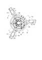
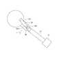
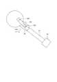
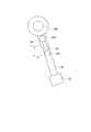
図1は、本発明の一例である実施の形態にかかるロボットハンド1の斜視図であり、図2は、ロボットハンド1の上面図である。また、図3は、ロボットハンド1の縦断面図であり、図2におけるA−A断面図である。
Hereinafter, embodiments of the present invention will be described with reference to the drawings.
The embodiments described below have both configurations of the first aspect of the present invention and the second aspect of the present invention.
FIG. 1 is a perspective view of the robot hand 1 according to the embodiment of the present invention, and FIG. 2 is a top view of the robot hand 1. Further, FIG. 3 is a vertical sectional view of the robot hand 1, and is a sectional view taken along the line AA in FIG.

なお、本実施の形態の説明において、上下、あるいは、上方、下方と云う時は、図1における上下関係を意味し、重力方向における上下関係とは、必ずしも一致しない。
ロボットハンド1は、3つの指部10a,10b,10c(第1指部10a、第2指部10b、第3指部10c)と、これら指部10a,10b,10cを支持する支持部20と、指部10a,10b,10cを駆動する第1駆動部30及び第2駆動部40と、を備えて概略構成されている。
In the description of the present embodiment, the terms "up and down", "up and down", and "down" mean the vertical relationship in FIG. 1, and do not necessarily match the vertical relationship in the direction of gravity.
The robot hand 1 includes threefinger portions 10a, 10b, 10c (first finger portion 10a,second finger portion 10b,third finger portion 10c), and asupport portion 20 that supports thesefinger portions 10a, 10b, 10c. Afirst drive unit 30 and asecond drive unit 40 for driving thefinger portions 10a, 10b, and 10c are provided.

支持部20は、ケーシング50に固定された支持台21と、支持台21に回転可能に固定されるとともに、当該支持台21から垂直に立ち上がるシャフト22と、シャフト22が嵌挿され、3つの指部10a,10b,10cの基端部が接続される支持環23とを有する。 Thesupport portion 20 is rotatably fixed to thesupport base 21 fixed to thecasing 50 and thesupport base 21, and theshaft 22 rising vertically from thesupport base 21 and theshaft 22 are fitted and inserted into thesupport portion 20 with three fingers. It has asupport ring 23 to which the base end portions of theportions 10a, 10b, and 10c are connected.

指部10a,10b,10cは、支持部20から上方(突出方向X)に突出しており、その先端には、対象物を主として把持するための先端部11a,11b,11cが設けられている。この突出方向Xは、シャフト22の軸(中心軸O)と平行である。なお、指部10a,10b,10cのそれぞれが突出する方向は、突出方向Xに対して角度を有して、例えば上方に向けて広がっていたり窄まっていたりしてもよく、複数の指部が突出する方向の平均(ベクトルで説明すれば、突出方向への3つのベクトルの和となる方向)が突出方向Xと一致していればよい。即ち、本発明において、複数の指部の突出方向とは、指部が突出する方向の平均(ベクトルの和)を意味するものとする。 Thefinger portions 10a, 10b, 10c project upward (protruding direction X) from thesupport portion 20, and thetip portions 11a, 11b, 11c for mainly gripping the object are provided at the tips thereof. The protruding direction X is parallel to the axis (central axis O) of theshaft 22. The direction in which each of thefinger portions 10a, 10b, and 10c protrudes may have an angle with respect to the protrusion direction X, and may be widened or narrowed upward, for example, a plurality of finger portions. It suffices if the average of the projecting directions (in the vector, the direction that is the sum of the three vectors in the projecting direction) coincides with the projecting direction X. That is, in the present invention, the protruding directions of the plurality of fingers mean the average (sum of vectors) of the directions in which the fingers protrude.

第1駆動部30は、ケーシング50に固定された第1モータ31と、シャフト22の下端に取り付けられたプーリ32と、第1モータ31の回転駆動力をプーリ32に伝えるために両者間に架け渡された無端ベルト33と、を有する。
シャフト22の外周には、ボールねじを構成するネジ溝(不図示)が形成されており、支持環23の内周に設けられた内ネジ状のネジ溝(不図示)と螺合している。支持環23は、シャフト22を軸とする回転方向の動きが規制されており、シャフト22が回転すると上下方向(シャフト22の軸方向)に動くようになっている。
Thefirst drive unit 30 spans thefirst motor 31 fixed to thecasing 50, the pulley 32 attached to the lower end of theshaft 22, and the pulley 32 in order to transmit the rotational driving force of thefirst motor 31 to the pulley 32. It has the passedendless belt 33 and.
A screw groove (not shown) constituting a ball screw is formed on the outer circumference of theshaft 22, and is screwed with an internal screw-shaped screw groove (not shown) provided on the inner circumference of thesupport ring 23. .. Thesupport ring 23 is restricted from moving in the rotation direction about theshaft 22, and moves in the vertical direction (axial direction of the shaft 22) when theshaft 22 rotates.

支持環23の上下動は、指部10a,10b,10cの基端部の上下動となり、指部10a,10b,10cのリンク構造から、指部10a,10b,10cの先端部11a,11b,11cの水平方向への移動に変換され、先端部11a,11b,11cが、図2における、中心点Cに向かう方向(矢印D1方向、閉方向)、あるいは、中心点Cから遠ざかる方向(矢印D2方向、開方向)に移動する。すなわち、指部10a,10b,10cの開閉動作を第1駆動部30が担っている。なお、先端部11a,11b,11cの水平方向への移動に変換する構成やその動きについては、後に詳述する。 The vertical movement of thesupport ring 23 is the vertical movement of the base end portions of thefinger portions 10a, 10b, 10c, and from the link structure of thefinger portions 10a, 10b, 10c, thetip portions 11a, 11b, of thefinger portions 10a, 10b, 10c, Converted to the horizontal movement of 11c, thetip portions 11a, 11b, 11c are in the direction toward the center point C (arrow D1 direction, closing direction) in FIG. 2 or the direction away from the center point C (arrow D2). Move in the direction (opening direction). That is, thefirst drive unit 30 is responsible for opening and closing thefinger portions 10a, 10b, and 10c. The configuration for converting thetip portions 11a, 11b, 11c into horizontal movement and the movement thereof will be described in detail later.

3つの指部10a,10b,10cの開閉動作に伴う全開状態および全閉状態において、それぞれの先端部11a,11b,11cの位置は、図2に示す平面視で中心軸Oを中心とした同心円上に位置している。また、3つの指部10a,10b,10cのうち、第1指部10aは、中心軸Oを中心とする周方向には移動せず固定されており、第2指部10bおよび第3指部10cは、第2駆動部40によって、中心軸Oを中心とする周方向に回動可能に設けられている。即ち、第2指部10bおよび第3指部10cは、本発明に云う「回動指部」に相当する。 In the fully open state and the fully closed state accompanying the opening and closing operations of the threefinger portions 10a, 10b, and 10c, the positions of thetip portions 11a, 11b, and 11c are concentric circles centered on the central axis O in the plan view shown in FIG. Located on top. Further, of the threefinger portions 10a, 10b, and 10c, thefirst finger portion 10a is fixed without moving in the circumferential direction about the central axis O, and thesecond finger portion 10b and the third finger portion are fixed. The 10c is rotatably provided in the circumferential direction about the central axis O by thesecond drive unit 40. That is, thesecond finger portion 10b and thethird finger portion 10c correspond to the "rotating finger portion" referred to in the present invention.

図2において、先端部11a,11b,11cは、120°の角度をもって等間隔(回転対称)に位置している。そして、本実施の形態においては、これら3つの先端部11a,11b,11cが、中心軸Oを中心とした同心円上に位置したまま、2つの先端部11b,11cが、互いに近づいたり遠ざかったりするように、回動可能になっている。 In FIG. 2, thetip portions 11a, 11b, 11c are located at equal intervals (rotational symmetry) at an angle of 120 °. Then, in the present embodiment, the twotip portions 11b, 11c move closer to each other or move away from each other while the threetip portions 11a, 11b, 11c are located on concentric circles centered on the central axis O. As such, it is rotatable.

図4は、3つの先端部が、第1指部110aから見た中心点C1の同心円上に位置せず、回動中心も一致しない状態となっている参考例の指部を模式的に示す模式平面図である。第1指部110aは中心点C1を中心とする周方向には移動せず固定されている。また、回動可能な第2指部110bおよび第3指部110cは、それぞれ回動中心がC2及びC3となっており、相互に一致しておらず、いずれも中心点C1とも一致していない。なお、図4において、それぞれの先端部111a,111b,111cは、模式的に丸形状で示している(以降の模式平面図において同様)。 FIG. 4 schematically shows a finger portion of a reference example in which the three tip portions are not located on the concentric circles of the center point C1 seen from thefirst finger portion 110a and the rotation centers do not match. It is a schematic plan view. Thefirst finger portion 110a does not move in the circumferential direction centered on the center point C1 and is fixed. Further, the rotatablesecond finger portion 110b and thethird finger portion 110c have rotation centers C2 and C3, respectively, and do not coincide with each other, nor do they coincide with the center point C1. .. In FIG. 4, therespective tip portions 111a, 111b, and 111c are schematically shown in a round shape (the same applies to the subsequent schematic plan views).

図4に示すように、本例では、第1指部110aから見た中心点C1に対して、第2指部110bおよび第3指部110cの回動中心C2,C3は、相互に逆方向に距離d分だけずれた位置にある。
図4においては、指部が閉じる際のそれぞれの先端部111a,111b,111cの移動方向を矢印V111a,V111b,V111cで示している。これら矢印V111a,V111b,V111cは、それぞれの先端部111a,111b,111cの動きのベクトルと捉えることができる(これらベクトルを「ベクトルV111a,V111b,V111c」と表記する。)。また、先端部111a,111b,111cの移動方向の延長が、図中一点鎖線で表されている。このように、本例では、先端部111a,111b,111cの動きのベクトルV111a,V111b,V111cが、1つの中心点に向かっておらず、先端部111aと先端部111b,111cとで、把持しようとする対象物に対する把持力が有効に生かされていない状態になっていることがわかる。
As shown in FIG. 4, in this example, the rotation centers C2 and C3 of thesecond finger portion 110b and thethird finger portion 110c are opposite to each other with respect to the center point C1 seen from thefirst finger portion 110a. It is located at a distance d.
In FIG. 4, the moving directions of thetip portions 111a, 111b, 111c when the finger portion is closed are indicated by arrows V111a , V111b , and V111c . These arrows V111a , V111b , and V111c can be regarded as motion vectors of therespective tip portions 111a, 111b, and 111c (these vectors are referred to as "vectors V111a , V111b , and V111c "). .. Further, the extension of thetip portions 111a, 111b, 111c in the moving direction is represented by a alternate long and short dash line in the figure. As described above, in this example, the motion vectors V111a , V111b , and V111c of thetip portions 111a, 111b, 111c do not face one center point, and thetip portions 111a and thetip portions 111b, 111c It can be seen that the gripping force on the object to be gripped is not effectively utilized.

即ち、把持しようとする対象物に対して、先端部111a,111b,111cがずれた方向からアクセスしているため、把持力が有効には生かされていない。また、把持しようとする対象物に、3つの先端部111a,111b,111cのうちのいずれかが最初に接触した際には、その接触した先端部のベクトルの方向に当該対象物が移動してしまい、特に先端部111b,111cのいずれかが最初に接触した場合には、把持の中心位置となるべき中心点C1からずれた方向に前記対象物が移動してしまう。そのため、把持がより困難になったり、把持力がより作用しづらくなり、把持の安定性が低下したりしてしまう。 That is, since thetip portions 111a, 111b, and 111c are accessing the object to be gripped from the displaced direction, the gripping force is not effectively utilized. Further, when any one of the threetip portions 111a, 111b, 111c first contacts the object to be gripped, the object moves in the direction of the vector of the contacted tip portion. In particular, when any of thetip portions 111b and 111c first comes into contact with each other, the object moves in a direction deviated from the center point C1 which should be the center position of gripping. Therefore, gripping becomes more difficult, gripping force becomes more difficult to act, and gripping stability is lowered.

第2指部110bおよび第3指部110cを回動中心C2,C3を軸として回動させた場合にも、ベクトルV111a,V111b,V111cが、1つの中心点で交差する状態以外では、上記の如きずれが生じたままであり把持力や把持の安定性の低下は避けられない。特に、先端部111bと先端部111cとの間の距離が近くなる(ベクトルV111aとベクトルV111cとの成す角が小さくなる)方向へ、第2指部110bおよび第3指部110cが回動して行くと、上記の如きずれによる影響がより顕著となってくる。Even when thesecond finger portion 110b and thethird finger portion 110c are rotated around the rotation centers C2 and C3, the vectors V111a , V111b , and V111c are not intersected at one center point. , The above-mentioned deviation still occurs, and a decrease in gripping force and gripping stability is unavoidable. In particular, thesecond finger portion 110b and thethird finger portion 110c rotate in the direction in which the distance between thetip portion 111b and thetip portion 111c becomes shorter (the angle formed by the vector V111a and the vector V111c becomes smaller). Then, the influence of the above deviation becomes more remarkable.

この先端部のベクトルの方向のずれによる把持力や把持の安定性の低下は、中心点C1と回動中心C2,C3との間の距離dが大きいほど顕著となる。これは逆に、このdの値が小さいほど把持力や把持の安定性が向上することを意味する。本実施の形態では、この距離dがゼロになっている、即ち、中心点C1と回動中心C2,C3とが全て一致している。 The decrease in gripping force and gripping stability due to the deviation of the vector at the tip portion becomes more remarkable as the distance d between the center point C1 and the rotation centers C2 and C3 increases. On the contrary, the smaller the value of d, the better the gripping force and the stability of gripping. In the present embodiment, this distance d is zero, that is, the center point C1 and the rotation centers C2 and C3 all coincide with each other.

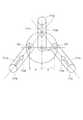
図5に、本実施の形態の指部を模式的に表す模式平面図を示す。図5に示されるように、本実施の形態では、3つの指部10a,10b,10cが閉じる際の先端部11a,11b,11cの動きのベクトルV11a,V11b,V11cが、1つの中心点Cに向かっている。また、回動指部を構成する第2指部10bおよび第3指部10cは、中心点Cを通る突出方向Xの線を中心軸Oとして回動可能となっている。そのため、第2指部10bおよび第3指部10cが回動してどの位置にあったとしても、指部10a,10b,10cが閉じる際の先端部11a,11b,11cの動きのベクトルV11a,V11b,V11cが、1つの中心点Cに向かっている。FIG. 5 shows a schematic plan view schematically showing the finger portion of the present embodiment. As shown in FIG. 5, in the present embodiment, one of the motion vectors V11a , V11b , and V11c of thetip portions 11a, 11b, and 11c when the threefinger portions 10a, 10b, and 10c are closed. It is heading toward the center point C. Further, thesecond finger portion 10b and thethird finger portion 10c constituting the rotating finger portion can be rotated around the line of the protruding direction X passing through the central point C as the central axis O. Therefore, no matter where thesecond finger portion 10b and thethird finger portion 10c rotate and are in any position, the motion vector V11a of thetip portions 11a, 11b, 11c when thefinger portions 10a, 10b, 10c are closed. , V11b , V11c are heading toward one center point C.

そのため、本実施の形態の態様によれば、先端部11a,11b,11cが全て中心軸Oに向かって動くため、中心軸O近傍に位置する対象物に対して、把持力が有効に生かされる。また、把持しようとする対象物に、3つの先端部11a,11b,11cのうちのいずれかが最初に接触した際にも、その接触した先端部のベクトルの方向に当該対象物が移動しても、それは、把持の中心位置となるべき中心点Cに向かって前記対象物が移動することになり、把持力が有効に作用するとともに、把持の安定性が高い。特に、サイズの小さな対象物を把持しようとする場合に、取りこぼすことなく把持することも可能である。 Therefore, according to the aspect of the present embodiment, since thetip portions 11a, 11b, and 11c all move toward the central axis O, the gripping force is effectively utilized for the object located near the central axis O. .. Further, when any one of the threetip portions 11a, 11b, and 11c first contacts the object to be gripped, the object moves in the direction of the vector of the contacted tip portion. However, it means that the object moves toward the center point C which should be the center position of the grip, the gripping force acts effectively, and the gripping stability is high. In particular, when trying to grip a small object, it is possible to grip the object without dropping it.

図6は、本実施の形態の指部において、回動指部を構成する第2指部10bおよび第3指部10cが回動して近づいた状態を模式的に表す模式平面図である。図6に示される通り、第2指部10bおよび第3指部10cが回動して近づいても、勿論、指部10a,10b,10cが閉じる際の先端部11a,11b,11cの動きのベクトルV11a,V11b,V11cは、1つの中心点Cに向かい、中心軸O近傍に位置する対象物に対して、把持力が有効に作用する。FIG. 6 is a schematic plan view schematically showing a state in which thesecond finger portion 10b and thethird finger portion 10c constituting the rotating finger portion rotate and approach each other in the finger portion of the present embodiment. As shown in FIG. 6, even if thesecond finger portion 10b and thethird finger portion 10c rotate and approach each other, of course, the movement of thetip portions 11a, 11b, 11c when thefinger portions 10a, 10b, 10c are closed In the vectors V11a , V11b , and V11c , the gripping force acts effectively on the object located near the central axis O toward one center point C.

また、把持しようとする対象物の形状が長尺状や直方体形状等の場合には、相互に平行な位置関係にある外表面を挟み込む際に、先端部11aの動きのベクトルV11aと、先端部11b,11cの動きのベクトルV11b,V11cとが対向状態に近いため、把持力の無駄が少なく、有効に把持することができる。Further, when the shape of the object to be gripped is a long shape, a rectangular parallelepiped shape, or the like, when sandwiching the outer surfaces having a positional relationship parallel to each other, the motion vector V11a of the tip portion11a and the tip Since the motion vectors V11b and V11c of the portions 11b and 11c are close to the opposite state, the gripping force is not wasted and the gripping force can be effectively gripped.

一方、図7は、本実施の形態の指部において、回動指部を構成する第2指部10bおよび第3指部10cが回動して遠ざかった状態を模式的に表す模式平面図である。図7に示される通り、第2指部10bおよび第3指部10cが回動して遠ざかっても、勿論、指部10a,10b,10cが閉じる際の先端部11a,11b,11cの動きのベクトルV11a,V11b,V11cは、1つの中心点Cに向かい、中心軸O近傍に位置する対象物に対して、把持力が有効に作用する。On the other hand, FIG. 7 is a schematic plan view schematically showing a state in which thesecond finger portion 10b and thethird finger portion 10c constituting the rotating finger portion are rotated away from each other in the finger portion of the present embodiment. is there. As shown in FIG. 7, even if thesecond finger portion 10b and thethird finger portion 10c rotate and move away, of course, the movement of thetip portions 11a, 11b, 11c when thefinger portions 10a, 10b, 10c closes. In the vectors V11a , V11b , and V11c , the gripping force acts effectively on the object located near the central axis O toward one center point C.

また、例えば、長尺物の端部を把持しようとする場合(この場合に当該対象物を本実施の形態のロボットハンド1で把持するに際しては、対象物の端部を先端部11aに当接させ、対象物の長手方向が第2指部10bおよび第3指部10cの間に位置するようにさせた上で、端部周辺の側面を先端部11b,11cに当接させることで把持させればよい。)等、把持しようとする対象物の形状によっては、先端部11b,11cの動きのベクトルV11b,V11cが角度を有していた方がよい場合もあり、そのような対象物の場合に、把持力の無駄が少なく、有効に把持することができる。Further, for example, when trying to grip the end of a long object (in this case, when grasping the object with the robot hand 1 of the present embodiment, the end of the object is in contact with thetip 11a. The object is held so that the longitudinal direction of the object is located between thesecond finger portion 10b and thethird finger portion 10c, and then the side surface around the end portion is brought into contact with thetip portions 11b and 11c. Depending on the shape of the object to be gripped, it may be better for the motion vectors V11b and V11c of thetip portions 11b and 11c to have an angle, and such an object. In the case of an object, there is little waste of gripping force and it is possible to grip effectively.

本実施の形態において、回動指部を構成する第2指部10bおよび第3指部10cの回動方向は、相互に逆方向となるようになっている。そのため、第2指部10bと第3指部10cとの間の距離を、把持する対象物の大きさや形状に応じた位置に、素早く調整することができる。 In the present embodiment, the rotation directions of thesecond finger portion 10b and thethird finger portion 10c constituting the rotating finger portion are opposite to each other. Therefore, the distance between thesecond finger portion 10b and thethird finger portion 10c can be quickly adjusted to a position according to the size and shape of the object to be gripped.

また、図5に示す通り、回動指部を構成する第2指部10bおよび第3指部10cの先端部11b,11cの対応箇所(図中のYb及びYc)同士を結ぶ線の中心点Pと、回動方向には固定された第1指部10aの先端部11aの中心とを結ぶ線Lが、中心点Cを通るようになっている。そのため、第1指部10aに対する第2指部10bおよび第3指部10cの位置関係が対等になり、3つの指部10a,10b,10cで対象物を均等に包み込むように把持したり、第1指部10aと第2指部10bおよび第3指部10cとで挟み込むように把持したり等、いずれの位置においてもバランスよく対象物を把持することができる。 Further, as shown in FIG. 5, the center point of the line connecting the corresponding portions (Yb and Yc in the figure) of thetip portions 11b and 11c of thesecond finger portion 10b and thethird finger portion 10c constituting the rotating finger portion. A line L connecting P and the center of thetip portion 11a of thefirst finger portion 10a fixed in the rotation direction passes through the center point C. Therefore, the positional relationship between thesecond finger portion 10b and thethird finger portion 10c with respect to thefirst finger portion 10a becomes equal, and the threefinger portions 10a, 10b, and 10c grip the object so as to evenly wrap the object. The object can be gripped in a well-balanced manner at any position, such as being sandwiched between thefirst finger portion 10a, thesecond finger portion 10b, and thethird finger portion 10c.

なお、本発明において、先端部(11b,11c)における「対応箇所」とは、先端部における中心位置同士、重心位置同士、中心軸Oに最も近い位置同士等、両先端部における形状としての対応する位置を指し、先端部11aの動きのベクトルV11aの延長線Lを基準として線対称となる位置に相当する。In the present invention, the "corresponding points" at the tip portions (11b, 11c) correspond to the shapes at both tip portions, such as the center positions at the tip portions, the center of gravity positions, and the positions closest to the central axis O. It points to a position where thetip 11a is to be moved, and corresponds to a position that is line-symmetric with respect to an extension line L of the motion vector V11a of thetip portion 11a.

以上の如きロボットハンド1の指部10a,10b,10cの動きを実現する、本実施の形態の具体的な装置構成について説明する。
図8は、本実施の形態にかかるロボットハンド1の縦断面図であり、図2におけるB−B断面図である。
A specific device configuration of the present embodiment that realizes the movements of thefingers 10a, 10b, and 10c of the robot hand 1 as described above will be described.
FIG. 8 is a vertical sectional view of the robot hand 1 according to the present embodiment, and is a sectional view taken along line BB in FIG.

第2駆動部40は、ケーシング50に固定された第2モータ41と、第2指部10bおよび第3指部10cを回動移動させるギアユニット42と、第2モータ41の回転を入力プーリ44に伝えるために両者間に架け渡された無端ベルト43と、ギアユニット42に回転を入力するための入力プーリ44と、を有する。ギアユニット42も、ケーシング50に固定されている。 Thesecond drive unit 40 inputs the rotation of thesecond motor 41 fixed to thecasing 50, thegear unit 42 for rotating thesecond finger portion 10b and thethird finger portion 10c, and the rotation of thesecond motor 41. It has anendless belt 43 bridged between them for transmitting to thegear unit 42, and aninput pulley 44 for inputting rotation to thegear unit 42. Thegear unit 42 is also fixed to thecasing 50.

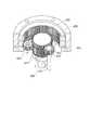
図9は、第2駆動部40からギアユニット42のみを取り出した拡大斜視図である。また、図10は、ギアユニット42の図9におけるE−E断面図であり、図11は、ギアユニット42の歯車群のみを表した(突出方向Xから見た)上面図である。
ギアユニット42は、回転太陽歯車421と、固定太陽歯車422と、伝達歯車423と、固定内歯車424と、回転内歯車425と、第1の遊星歯車426と、第2の遊星歯車427と、を含んで構成される。これらがギアユニットケース428内に組み込まれて、一体となったギアユニット42が形成されている。
FIG. 9 is an enlarged perspective view in which only thegear unit 42 is taken out from thesecond drive unit 40. Further, FIG. 10 is a cross-sectional view taken along the line EE in FIG. 9 of thegear unit 42, and FIG. 11 is a top view (viewed from the protruding direction X) showing only the gear group of thegear unit 42.
Thegear unit 42 includes arotary sun gear 421, a fixedsun gear 422, atransmission gear 423, a fixedinternal gear 424, a rotaryinternal gear 425, a firstplanetary gear 426, and a secondplanetary gear 427. Consists of including. These are incorporated in thegear unit case 428 to form anintegrated gear unit 42.

回転太陽歯車421と固定太陽歯車422は、ロボットハンド1の中心軸Oを軸とする同心上で重ねられて配置された、上面視で同一形状かつ同一個数の外歯を有する外歯車である。ただし、固定太陽歯車422が固定されて回転しないのに対して、回転太陽歯車421はこれとは独立して回転可能になっている。なお、回転太陽歯車421は、固定太陽歯車422よりも厚み(中心軸O方向高さ)が大きくなっている。 Therotary sun gear 421 and the fixedsun gear 422 are external gears having the same shape and the same number of external teeth in the top view, which are arranged concentrically overlapped with respect to the central axis O of the robot hand 1. However, while the fixedsun gear 422 is fixed and does not rotate, therotating sun gear 421 can rotate independently of the fixedsun gear 422. Therotary sun gear 421 has a larger thickness (height in the central axis O direction) than the fixedsun gear 422.

固定内歯車424と回転内歯車425は、同心上で重ねられて配置された、上面視で同一形状かつ同一個数の内歯を有する内歯車ではある。ただし、固定内歯車424が固定されて回転しないのに対して、回転内歯車425はこれとは独立して回転可能になっている。なお、回転内歯車425は、固定内歯車424よりも厚み(中心軸O方向高さ)が大きくなっている。 The fixedinternal gear 424 and the rotaryinternal gear 425 are concentrically arranged internal gears having the same shape and the same number of internal teeth in a top view. However, while the fixedinternal gear 424 is fixed and does not rotate, the rotatinginternal gear 425 can rotate independently of the fixedinternal gear 424. The rotaryinternal gear 425 has a larger thickness (height in the central axis O direction) than the fixedinternal gear 424.

回転太陽歯車421は、中心軸O方向における下方(突出方向Xとは逆側。以下同様。)に位置し、その下方側の外歯が固定内歯車424の内歯と対向し、その上方(突出方向X側。以下同様。)の外歯が回転内歯車425の下方の内歯と対向している。また、回転内歯車425の上方の内歯は、固定太陽歯車422の外歯と対向している。 Therotary sun gear 421 is located below the central axis O direction (opposite the protrusion direction X; the same applies hereinafter), and the outer teeth on the lower side face the internal teeth of the fixedinternal gear 424 and above it (the opposite side). The outer teeth in the protruding direction X side; the same applies hereinafter) face the inner teeth below the rotaryinternal gear 425. Further, the internal teeth above the rotaryinternal gear 425 face the external teeth of the fixedsun gear 422.

回転太陽歯車421と固定内歯車424との間には、第1の遊星歯車426が、両歯車とギアが噛み合った状態で介在している。また、回転太陽歯車421と回転内歯車425との間には、軸が固定されて回転可能な伝達歯車423が、両歯車と歯合しながら介在している。そして、回転内歯車425と固定太陽歯車422との間には、第2の遊星歯車427が、両歯車と歯合しながら介在している。 A firstplanetary gear 426 is interposed between therotary sun gear 421 and the fixedinternal gear 424 in a state where both gears and gears are in mesh with each other. Further, atransmission gear 423 having a fixed shaft and rotatable is interposed between therotary sun gear 421 and the rotaryinternal gear 425 while meshing with both gears. A secondplanetary gear 427 is interposed between the rotaryinternal gear 425 and the fixedsun gear 422 while meshing with both gears.

入力プーリ44は、シャフト22の上方で当該シャフト22と同軸に配された端部429に配されるとともに、当該軸部429を介して回転太陽歯車421に回転を入力する。ここでは、入力プーリ44から回転太陽歯車421に、矢印F方向(時計回り)の回転が入力された場合を例に挙げて説明する。なお、図11において、回転太陽歯車421は、固定太陽歯車422の陰に隠れており、その歯先のみが見えている。 Theinput pulley 44 is arranged above theshaft 22 at anend portion 429 coaxially arranged with theshaft portion 22, and inputs rotation to therotating sun gear 421 via theshaft portion 429. Here, a case where rotation in the arrow F direction (clockwise) is input from theinput pulley 44 to therotary sun gear 421 will be described as an example. In FIG. 11, therotary sun gear 421 is hidden behind the fixedsun gear 422, and only the tooth tips thereof are visible.

回転太陽歯車421に入力された矢印F方向の回転は、第1の遊星歯車426に伝達され、第1の遊星歯車426を逆回転(反時計回り)、即ち矢印G方向に自転させる。すると、第1の遊星歯車426は、自転しながら固定内歯車424の内周を周回し、矢印H方向(時計回り)に移動(公転)する。 The rotation in the arrow F direction input to therotary sun gear 421 is transmitted to the firstplanetary gear 426, and the firstplanetary gear 426 is rotated in the reverse direction (counterclockwise), that is, in the direction of the arrow G. Then, the firstplanetary gear 426 orbits the inner circumference of the fixedinternal gear 424 while rotating, and moves (revolves) in the arrow H direction (clockwise).

また、回転太陽歯車421に入力された矢印F方向の回転は、伝達歯車423にも伝達され、伝達歯車423を逆回転(反時計回り)、即ち矢印I方向に回転させる。すると、伝達歯車423は、その場で自転しながら回転内歯車425に回転を伝達し、回転内歯車425を矢印J方向(反時計回り)に回転させる。 Further, the rotation in the arrow F direction input to therotary sun gear 421 is also transmitted to thetransmission gear 423, causing thetransmission gear 423 to rotate in the reverse direction (counterclockwise), that is, in the arrow I direction. Then, thetransmission gear 423 transmits the rotation to the rotaryinternal gear 425 while rotating on the spot, and rotates the rotaryinternal gear 425 in the arrow J direction (counterclockwise).

さらに、回転内歯車425に伝達された矢印J方向の回転は、第2の遊星歯車427に伝達され、第2の遊星歯車427を同回転(反時計回り)、即ち矢印K方向に自転させる。すると、第2の遊星歯車427は、自転しながら固定太陽歯車422の外周を周回し、矢印M方向(反時計回り)に移動(公転)する。 Further, the rotation in the arrow J direction transmitted to the rotatinginternal gear 425 is transmitted to the secondplanetary gear 427, and the secondplanetary gear 427 rotates in the same rotation (counterclockwise), that is, in the arrow K direction. Then, the secondplanetary gear 427 orbits the outer circumference of the fixedsun gear 422 while rotating, and moves (revolves) in the arrow M direction (counterclockwise).

以上のようにして、第2モータ41から、入力プーリ44を介して、回転太陽歯車421に矢印F方向(時計回り)の回転が入力されると、第1の遊星歯車426が矢印H方向(時計回り)に、第2の遊星歯車427が矢印M方向(反時計回り)に、それぞれ公転し、両歯車が互いに近づくように移動する。 As described above, when the rotation in the arrow F direction (clockwise) is input from thesecond motor 41 to therotary sun gear 421 via theinput pulley 44, the firstplanetary gear 426 is moved in the arrow H direction (clockwise). (Clockwise), the secondplanetary gear 427 revolves in the direction of arrow M (counterclockwise), and both gears move so as to approach each other.

それに対して、回転太陽歯車421に矢印F方向とは逆方向(反時計回り)の回転が入力された場合には、全ての歯車が、それぞれ以上説明した回転方向とは逆方向に回転する。そして、最終的に、第1の遊星歯車426が矢印M方向(反時計回り)に、第2の遊星歯車427が矢印H方向(時計回り)に、それぞれ公転し、両歯車が互いに遠ざかるように移動する。 On the other hand, when the rotation in the direction opposite to the arrow F direction (counterclockwise) is input to therotating sun gear 421, all the gears rotate in the direction opposite to the rotation direction described above. Finally, the firstplanetary gear 426 revolves in the arrow M direction (counterclockwise) and the secondplanetary gear 427 revolves in the arrow H direction (clockwise) so that both gears move away from each other. Moving.

図12に、ギアユニット42直下におけるロボットハンド1の横断面拡大図(図8におけるN−N拡大断面)を示す。
第1の遊星歯車426には、第1回動シャフト24b(図8、図11及び図12参照。図9及び図10では不図示)が、回転自在に嵌挿されて取り付けられている。第1の遊星歯車426の矢印Hあるいは矢印M方向への公転と共に第1回動シャフト24bも連れ回り、中心軸Oを軸として、回動移動する。この回動運動が、リンク部25bを介して第2指部10bへと伝達される。
FIG. 12 shows an enlarged cross-sectional view of the robot hand 1 immediately below the gear unit 42 (enlarged NN cross section in FIG. 8).
A firstrotating shaft 24b (see FIGS. 8, 11 and 12, not shown in FIGS. 9 and 10) is rotatably inserted and attached to the firstplanetary gear 426. Along with the revolution of the firstplanetary gear 426 in the direction of the arrow H or the arrow M, the firstrotating shaft 24b also rotates and moves around the central axis O. This rotational movement is transmitted to thesecond finger portion 10b via thelink portion 25b.

リンク部25bは、シャフト22に回転自在に固定される回転リング部25b1と、中途で第2回動シャフト24cが回転自在に嵌挿され、シャフト22から離れた側の端部で第2指部10b(詳しくは、後述する指リンク部材)に接合される回動リンク部25b2と、を有する。これにより、第1の遊星歯車426の公転移動が、第2指部10bの回動動作となる。 Thelink portion 25b has a rotating ring portion 25b1 rotatably fixed to theshaft 22 and a secondrotating shaft 24c rotatably inserted in the middle of thelink portion 25b, and a second finger portion at an end portion on the side away from theshaft 22. It has a rotating link portion 25b2 joined to 10b (more specifically, a finger link member described later). As a result, the revolution movement of the firstplanetary gear 426 becomes the rotation operation of thesecond finger portion 10b.

また、第2の遊星歯車427には、第2回動シャフト24c(図9〜図12参照。図8では不図示)が、回転自在に嵌挿されて取り付けられている。第2の遊星歯車427の矢印Mあるいは矢印H方向への公転と共に第2回動シャフト24cも連れ回り、中心軸Oを軸として、回動移動する。この回動運動が、後述するリンク部25cを介して第3指部10cへと伝達されて、当該第3指部10cの回動動作となる。 Further, a secondrotating shaft 24c (see FIGS. 9 to 12; not shown in FIG. 8) is rotatably inserted and attached to the secondplanetary gear 427. Along with the revolution of the secondplanetary gear 427 in the direction of the arrow M or the arrow H, the secondrotating shaft 24c also rotates and moves around the central axis O. This rotational movement is transmitted to thethird finger portion 10c via thelink portion 25c described later, and becomes the rotational movement of thethird finger portion 10c.

リンク部25cもリンク部25bと同様、回転リング部と回動リンク部25c2と、を有するが、リンク部25cの回転リング部は、回転リング部25b1と重なった状態でシャフト22に回転自在に固定されているため、図12には現れていない。リンク部25cの回転リング部は、回動リンク部25b1とは独立して、シャフト22に回転自在に固定されている。そして、リンク部25cの回転リング部25b1は、回動リンク部25b2と一体になっており、当該回動リンク部25b2に第3指部10c(詳しくは、後述する指リンク部材)が接合されている。これにより、第2の遊星歯車427の公転移動が、第3指部10cの回動動作となる。 Like thelink portion 25b, thelink portion 25c also has a rotating ring portion and a rotating link portion 25c2, but the rotating ring portion of thelink portion 25c is rotatably fixed to theshaft 22 in a state of being overlapped with the rotating ring portion 25b1. Therefore, it does not appear in FIG. The rotating ring portion of thelink portion 25c is rotatably fixed to theshaft 22 independently of the rotating link portion 25b1. The rotating ring portion 25b1 of thelink portion 25c is integrated with the rotating link portion 25b2, and thethird finger portion 10c (more specifically, a finger link member described later) is joined to the rotating link portion 25b2. There is. As a result, the revolution movement of the secondplanetary gear 427 becomes the rotation operation of thethird finger portion 10c.

なお、リンク部25b及びリンク部25cの回転リング部(不図示及び25c2)は、後述する支持環23または固定環51(図25参照)の一部を構成する。支持環23または固定環51のいずれの一部であっても、回転リング部(不図示及び25c2)は、支持環23あるいは固定環51の他の部分に回転自在に接続されて構成される。したがって、回転リング部(不図示及び25c2)が支持環23の一部を構成する場合には、支持環23の上下動に伴って、回転リング部(不図示及び25c2)が上下動する。 Thelink portion 25b and the rotating ring portion (not shown and 25c2) of thelink portion 25c form a part of thesupport ring 23 or the fixed ring 51 (see FIG. 25) described later. The rotating ring portion (not shown and 25c2) of either thesupport ring 23 or the fixedring 51 is rotatably connected to thesupport ring 23 or another part of the fixedring 51. Therefore, when the rotating ring portion (not shown and 25c2) constitutes a part of thesupport ring 23, the rotating ring portion (not shown and 25c2) moves up and down as thesupport ring 23 moves up and down.

以上、説明したように、回動指部を構成する第2指部10bおよび第3指部10cは、中心軸Oを中心とする周方向に回動可能に設けられている。そのため、図6に示すように、第2指部10bおよび第3指部10cが回動して近づくことによって、先端部11b,11cの動きのベクトルV11b,V11cは、先端部11aの動きのベクトルV11aの対向状態に近づけることはできる。As described above, thesecond finger portion 10b and thethird finger portion 10c constituting the rotating finger portion are provided so as to be rotatable in the circumferential direction about the central axis O. Therefore, as shown in FIG. 6, when thesecond finger portion 10b and thethird finger portion 10c rotate and approach each other, the motion vectors V11b and V11c of the tip portions11b and11c are the movements of thetip portion 11a. It is possible to approach the opposite state of the vector V11a of.

しかし、両指部の中心軸Oから先端部11b,11cまでの構造が単に直線状のリンク(模式図である図4〜6及び図13の指部10b,10cの状態)であると、図13に示すように干渉が生じてしまうため、対向状態(ベクトルの向きが逆の平行状態)になるまで近づけることはできない。 However, if the structure from the central axis O of both finger portions to thetip portions 11b and 11c is simply a linear link (states of thefinger portions 10b and 10c in FIGS. 4 to 6 and 13 in FIG. 13), the figure shows. Since interference occurs as shown in No. 13, it is not possible to bring them closer to each other until they are in a facing state (parallel states in which the directions of the vectors are opposite).

なお、図13は、本実施の形態の指部における中心軸Oから先端部11b,11cまでの構造を単なる直線状のリンクに置き換えた場合の、回動指部を構成する第2指部10bおよび第3指部10cが回動して近づいた状態を模式的に表す模式平面図である。第2指部10bと第3指部10cとが近づきすぎると、第2指部10bおよび第3指部10cにおけるいずれかの箇所が干渉してしまい、それ以上第2指部10bと第3指部10cとを近づけることができない限界がある。 Note that FIG. 13 shows thesecond finger portion 10b constituting the rotating finger portion when the structure from the central axis O to thetip portions 11b and 11c in the finger portion of the present embodiment is replaced with a simple linear link. It is a schematic plan view which shows typically the state which the3rd finger part 10c is rotated and approached. If thesecond finger portion 10b and thethird finger portion 10c are too close to each other, any of thesecond finger portion 10b and thethird finger portion 10c will interfere with each other, and thesecond finger portion 10b and the third finger portion will further interfere with each other. There is a limit that cannot be brought close to thepart 10c.

一方、図14は、図4に示す参考例の指部において、回動指部を構成する第2指部110bおよび第3指部110cの先端部111b,111cの移動方向の両ベクトルが、第1指部110aの先端部111aの移動方向のベクトルに対向するまで、第2指部110bおよび第3指部110cを近づけた状態を模式的に示す模式平面図である。 On the other hand, in FIG. 14, in the finger portion of the reference example shown in FIG. 4, both vectors in the moving directions of thesecond finger portion 110b and thetip portions 111b and 111c of thethird finger portion 110c constituting the rotating finger portion are the first. It is a schematic plan view which shows typically the state that the2nd finger part 110b and the3rd finger part 110c are brought close to each other until it opposes the vector of thetip part 111a of 1finger part 110a in the moving direction.

このように、第1指部110aから見た中心点C1に対して、回動指部を構成する第2指部110bおよび第3指部110cの回動中心C2,C3が、相互に逆方向にずれた状態になっているため、第2指部110bと第3指部110cとの間で干渉が生じることがない。よって、この参考例においては、図14に示されるように、第2指部110bと第3指部110cとを、先端部111aの動きのベクトルV111aと、先端部111b,111cの動きのベクトルV111b,V111cとが、対向状態(ベクトルの向きが逆の平行状態)になるまで、近づけることができることがわかる。In this way, the rotation centers C2 and C3 of thesecond finger portion 110b and thethird finger portion 110c constituting the rotation finger portion are in opposite directions with respect to the center point C1 seen from thefirst finger portion 110a. Since it is in a state of being displaced to, interference does not occur between thesecond finger portion 110b and thethird finger portion 110c. Therefore, in this reference example, as shown in FIG. 14, thesecond finger portion 110b and thethird finger portion 110c are the motion vector V111a of the tip portion111a and the motion vector of thetip portions 111b and 111c. It can be seen that V111b and V111c can be brought close to each other until they are in a facing state (parallel states in which the directions of the vectors are opposite to each other).

そこで本実施の形態においては、回動指部を構成する第2指部110bおよび第3指部110cと、中心軸Oと、の間に、2本のリンク部材からなるリンク部を介在させることで、先端部11b,11cの動きのベクトルV11b,V11cが、先端部11aの動きのベクトルV11aに対して対向状態となることを実現している。Therefore, in the present embodiment, a link portion composed of two link members is interposed between thesecond finger portion 110b and thethird finger portion 110c constituting the rotating finger portion and the central axis O. Therefore, it is realized that the motion vectors V11b and V11c of the tip portions11b and11c are opposed to the motion vector V11a of thetip portions 11a.

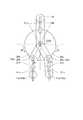
図15は、本実施の形態の指部において、回動指部を構成する第2指部10bおよび第3指部10cの先端部11b,11cの移動方向の両ベクトルが、第1指部10aの先端部11aの移動方向のベクトルに対向するまで、第2指部10bおよび第3指部10cを近づけた状態を模式的に示す模式平面図である。 In FIG. 15, in the finger portion of the present embodiment, both vectors of the moving directions of thesecond finger portion 10b and thetip portions 11b and 11c of thethird finger portion 10c forming the rotating finger portion are thefirst finger portion 10a. It is a schematic plan view which shows typically the state that the2nd finger part 10b and the3rd finger part 10c are brought close to each other until it faces the vector of the moving direction of thetip part 11a.

なお、図15においては、リンク部25bの中心点C(中心軸O)とは反対側の端部が、第2指部10bおよび第3指部10cの先端部11b,11cとは反対側の端部近傍と接続しているのであるが、模式的に途中の指リンク部等(後述する)の構成の図示を省略し、先端部11b,11cのみを図示している。また、リンク部25bと中心点C(中心軸O)との接続部に形成される、既述の回転リング部25b1の図示も省略し、既述の回動リンク部25b2,25c2(符号25c2は図12において不図示)のみリンク部25b,25cとして図示している。 In FIG. 15, the end portion of thelink portion 25b opposite to the center point C (central axis O) is opposite to thetip portions 11b and 11c of thesecond finger portion 10b and thethird finger portion 10c. Although it is connected to the vicinity of the end portion, the configuration of the finger link portion and the like (described later) in the middle is schematically omitted, and only thetip portions 11b and 11c are shown. Further, the above-described rotating ring portion 25b1 formed at the connection portion between thelink portion 25b and the center point C (central axis O) is also omitted, and the above-described rotating link portions 25b2 and 25c2 (reference numerals 25c2 are Only thelink portions 25b and 25c (not shown in FIG. 12) are shown.

図15に示されるように、本実施の形態のロボットハンド1では、一端が中心軸O(中心点C)を軸として回動可能に固定され、他端が回動指部10b(詳しくは、先端部11bとは反対側の端部近傍)と接続するリンク部25b,25cを有する。また、当該リンク部25b,25cが、その中途で、それぞれのリンク部25b,25cの既述の回動方向(矢印M及び矢印H、本発明に云う「第1の回動方向」)に沿った第2の回動(両矢印R,S)を可能とする連結部28b,28cで接続された第1のリンク部材26b,27b及び第2のリンク部材26c,27cを有する。 As shown in FIG. 15, in the robot hand 1 of the present embodiment, one end is rotatably fixed around the central axis O (center point C), and the other end is therotating finger portion 10b (specifically, for details, It haslink portions 25b and 25c connected to the end portion on the opposite side of thetip portion 11b). Further, thelink portions 25b and 25c follow the above-described rotation directions (arrow M and arrow H, "first rotation direction" referred to in the present invention) of therespective link portions 25b and 25c in the middle of the process. It also hasfirst link members 26b, 27b andsecond link members 26c, 27c connected by connectingportions 28b, 28c that enable second rotation (double-headed arrows R, S).

このように、本実施の形態では、リンク部25b,25cにおける第1のリンク部材26b,26cを第2指部10bおよび第3指部10cの間に干渉が生じない程度まで近づけるように矢印M及び矢印H方向(第1の回動方向)にそれぞれ回動させる。同時に、または、前後して、連結部28b,28cを軸として、第2のリンク部材27b,27cを矢印R及び矢印S方向の回動(第2の回動)のうちの互いに近づく方向に回動させる。 As described above, in the present embodiment, the arrow M is such that thefirst link members 26b, 26c in thelink portions 25b, 25c are brought close to each other so as not to cause interference between thesecond finger portion 10b and thethird finger portion 10c. And the arrow H direction (first rotation direction). At the same time or back and forth, thesecond link members 27b and 27c are rotated around the connectingportions 28b and 28c in the directions closer to each other among the rotations in the directions of arrows R and S (second rotation). Move it.

以上のようにして、本実施の形態では、第2指部10bと第3指部10cとを、先端部11aの動きのベクトルV11aと、先端部11b,11cの動きのベクトルV11b,V11cとが、対向状態(ベクトルの向きが逆の平行状態)になるまで、近づけることができることがわかる。As described above, in the present embodiment, thesecond finger portion 10b and thethird finger portion 10c are the motion vector V11a of the tip portion11a and the motion vector V11b , V of thetip portions 11b, 11c. It can be seen that11c can be brought close to each other until they are in a facing state (parallel states in which the directions of the vectors are opposite).

回動指部を構成する第2指部10bおよび第3指部10cにおける以上の動きについて、本実施の形態で採用した例を、模式的に示す図16〜図22を用いて、以下に詳細に説明する。なお、以下の説明においては、第2指部10bおよび第3指部10cに共通の構成を説明するため、両者の別を識別するための末尾の符号b,cを省略する。 The above movements of thesecond finger portion 10b and thethird finger portion 10c constituting the rotating finger portion are described in detail below with reference to FIGS. 16 to 22 schematically showing an example adopted in the present embodiment. Explain to. In the following description, in order to explain the configuration common to thesecond finger portion 10b and thethird finger portion 10c, the reference numerals b and c at the end for distinguishing the two are omitted.

図16は、リンク部25の第2の回動を説明するための図であり、対象箇所のみを抜き出し、下方から見た模式平面図である。また、図17は、図16の構成を横方向から見た模式側面図である。図16及び図17に示すように、リンク部25は、一端(図12における回転リング部25b1に相当)がシャフト22に回動可能に固定された第1のリンク部材26と、当該第1のリンク部材26に、連結部28で回動可能に接続された第2のリンク部材27を有する。当該第2のリンク部材27は、指部10(正確には、先端部11とは反対側の端部近傍)と接続している。 FIG. 16 is a diagram for explaining the second rotation of thelink portion 25, and is a schematic plan view of only the target portion extracted and viewed from below. Further, FIG. 17 is a schematic side view of the configuration of FIG. 16 as viewed from the lateral direction. As shown in FIGS. 16 and 17, thelink portion 25 includes afirst link member 26 having one end (corresponding to the rotating ring portion 25b1 in FIG. 12) rotatably fixed to theshaft 22 and thefirst link portion 26. Thelink member 26 has asecond link member 27 that is rotatably connected by the connectingportion 28. Thesecond link member 27 is connected to the finger portion 10 (to be exact, in the vicinity of the end portion on the opposite side of the tip portion 11).

また、第2のリンク部材27には、駆動リンク29の一端が回転自在に接続部291で接続されている。この駆動リンク29の他端は、シャフト22に接続部292で回転可能に接続されている。また、駆動リンク29の中途の接続部293から、回動シャフト24(既述の第1回動シャフト24bまたは第2回動シャフト24c)が上下方向に延伸している。この回動シャフト24は、第1の遊星歯車426あるいは第2の遊星歯車427とともに回動移動(公転)するようになっている。 Further, one end of thedrive link 29 is rotatably connected to thesecond link member 27 by a connectingportion 291. The other end of thedrive link 29 is rotatably connected to theshaft 22 by a connectingportion 292. Further, the rotating shaft 24 (the firstrotating shaft 24b or the secondrotating shaft 24c described above) extends in the vertical direction from the connectingportion 293 in the middle of thedrive link 29. The rotatingshaft 24 is adapted to rotate (revolve) together with the firstplanetary gear 426 or the secondplanetary gear 427.

図18は、リンク部25及びその周辺部のみを抜き出し、かつ、駆動リンク29を除した状態で示す模式平面図である。第1のリンク部材26には、下方に向けて突出する凸部261が設けられていて、ロックリンク52の一端に形成された長手方向に長孔状の開口522が係止されている。ロックリンク52の他端では、接続部521で、ケーシング50に対して回転自在に接続されている(不図示)。 FIG. 18 is a schematic plan view showing a state in which only thelink portion 25 and its peripheral portion are extracted and thedrive link 29 is removed. Thefirst link member 26 is provided with aconvex portion 261 that projects downward, and a long hole-shapedopening 522 formed at one end of thelock link 52 is locked in the longitudinal direction. At the other end of thelock link 52, a connectingportion 521 is rotatably connected to the casing 50 (not shown).

第1のリンク部材26が矢印T方向へ回動すると、図19に示すように、凸部261がロックリンク52の長孔状の開口522の端部に達した段階で、回動が規制されるようになっている。そのため、第1のリンク部材26は、矢印T方向への第1の回動が規制される。その段階までは、第1のリンク部材26と第2のリンク部材27とが、一直線上になって第1の回動がされるようになっている。以下、これを前提に説明を進める。
なお、図19は、図18の状態から、第1のリンク部材26が矢印T方向へ回動した状態を示す模式平面図である。
When thefirst link member 26 rotates in the direction of arrow T, the rotation is restricted when theconvex portion 261 reaches the end of the elongated hole-shapedopening 522 of thelock link 52, as shown in FIG. It has become so. Therefore, the first rotation of thefirst link member 26 in the arrow T direction is restricted. Until that stage, thefirst link member 26 and thesecond link member 27 are aligned and the first rotation is performed. Hereinafter, the explanation will proceed on the premise of this.
Note that FIG. 19 is a schematic plan view showing a state in which thefirst link member 26 is rotated in the arrow T direction from the state of FIG.

図20は、リンク部25及びその周辺部のみを抜き出した模式平面図である。当該図では、駆動リンク29は現れているが、ロックリンク52は陰に隠れて、図16及び図17と同様、不図示となっている。この状態は、図16の状態から、矢印T方向への回動が進み、ロックリンク52の作用によって、第1のリンク部材26の第1の回動が規制され始めた状態を表している。 FIG. 20 is a schematic plan view in which only thelink portion 25 and its peripheral portion are extracted. In the figure, thedrive link 29 appears, but thelock link 52 is hidden behind it and is not shown as in FIGS. 16 and 17. This state represents a state in which the rotation in the direction of the arrow T has progressed from the state of FIG. 16 and the first rotation of thefirst link member 26 has begun to be regulated by the action of thelock link 52.

図21は、図20の状態から、第1の遊星歯車426あるいは第2の遊星歯車427、及び、回動シャフト24の回動(公転)がさらに進み、第2のリンク部材27が第2の回動をした状態を示す模式平面図である。ロックリンク52の作用により第1のリンク部材26の第1の回動が規制されても、回動シャフト24との接続点の回動はそのまま進み、連結部28を軸として、第2のリンク部材27の第2の回動を生じさせる。 In FIG. 21, from the state of FIG. 20, the rotation (revolution) of the firstplanetary gear 426 or the secondplanetary gear 427 and therotation shaft 24 further progresses, and thesecond link member 27 is the second. It is a schematic plan view which shows the rotating state. Even if the first rotation of thefirst link member 26 is restricted by the action of thelock link 52, the rotation of the connection point with therotation shaft 24 proceeds as it is, and the second link is centered on the connectingportion 28. It causes a second rotation of themember 27.

本実施の形態では、以上のようにして、リンク部25における第1の回動と第2の回動を実現している。
図22は、図20に示す構成から、主としてリンク部25のみを抜き出して示す模式平面図である。
In the present embodiment, the first rotation and the second rotation of thelink portion 25 are realized as described above.
FIG. 22 is a schematic plan view showing mainly only thelink portion 25 extracted from the configuration shown in FIG. 20.

以上説明した回動を実現するために、図22に示すように、回動シャフト24の移動を許容するべく、第1のリンク部材26には、当該回動シャフト24が貫通する長孔状の開口部262が設けられている。また、第2のリンク部材27の第2の回動が所定の位置(図15に示す状態)で終了するように、駆動リンク29との接続点291が適度に移動できるように、第2のリンク部材27における接続箇所が、長孔状の開口部271となっている。 In order to realize the rotation described above, as shown in FIG. 22, in order to allow therotation shaft 24 to move, thefirst link member 26 has an elongated hole shape through which therotation shaft 24 penetrates. Anopening 262 is provided. In addition, theconnection point 291 with thedrive link 29 can be appropriately moved so that the second rotation of thesecond link member 27 ends at a predetermined position (state shown in FIG. 15). The connection point in thelink member 27 is an elongated hole-shapedopening 271.

図23は、本実施の形態のロボットハンド1から指部及びその回動機構のみを抜き出した、上方から見た平面図である。また、図24は、図23に示す状態から、回動指部の先端部の移動方向の両ベクトルが、残りの指部の先端部の移動方向のベクトルに対向するまで、2つの回動指部を近づけた状態を示す平面図である。 FIG. 23 is a plan view of the robot hand 1 of the present embodiment, in which only the finger portion and its rotating mechanism are extracted, as viewed from above. Further, FIG. 24 shows two rotating fingers from the state shown in FIG. 23 until both vectors in the moving direction of the tip of the rotating finger face the vector in the moving direction of the tip of the remaining finger. It is a top view which shows the state which brought the part close to each other.

図23及び図24において、ロックリンク52b,52cは現れているが、駆動リンク29は陰に隠れて現れていない。また、リンク部25b,25cについても、第2のリンク部材27b,27cの一部のみが現れているが、第1のリンク部材26b,26cは陰に隠れて現れていない。 In FIGS. 23 and 24, the lock links 52b and 52c appear, but thedrive link 29 does not appear behind the scenes. Further, as for thelink portions 25b and 25c, only a part of thesecond link members 27b and 27c appears, but thefirst link members 26b and 26c do not appear behind the scenes.

図23において、第1指部10a、第2指部10bおよび第3指部10cは、中心軸Oを中心にして、相互に120°の等間隔で(回転対称に)位置している。この状態から、既述の通り、ギアユニット42における第1の遊星歯車426及び第2の遊星歯車427の動きが第1回動シャフト24b及び第2回動シャフト24cを介してリンク部25b,25cに伝えられ、第2指部10bおよび第3指部10cが矢印T方向(図15で云えば、矢印M,H方向)に移動する。 In FIG. 23, thefirst finger portion 10a, thesecond finger portion 10b, and thethird finger portion 10c are located at equal intervals (rotationally symmetrical) of 120 ° with respect to the central axis O. From this state, as described above, the movements of the firstplanetary gear 426 and the secondplanetary gear 427 in thegear unit 42 pass through the firstrotating shaft 24b and the secondrotating shaft 24c, and thelink portions 25b and 25c. Thesecond finger portion 10b and thethird finger portion 10c move in the arrow T direction (in the case of FIG. 15, the arrows M and H directions).

ロックリンク52b,52cが作用して、図23では不図示の第1のリンク部材26b,26cの回動が規制されるが、駆動リンク29に伝えられた第1回動シャフト24b及び第2回動シャフト24cの回動によって、図24に示すように、第2のリンク部材27b,27cの矢印U方向への回動となる。そして最終的に、図24に示すように、第2指部10bおよび第3指部10cが平行に並び、第1指部10aと完全に対向した状態となる。 The lock links 52b and 52c act to restrict the rotation of thefirst link members 26b and 26c (not shown in FIG. 23), but thefirst rotation shaft 24b and thesecond rotation shaft 24b transmitted to thedrive link 29. The rotation of the movingshaft 24c causes thesecond link members 27b and 27c to rotate in the direction of the arrow U, as shown in FIG. Finally, as shown in FIG. 24, thesecond finger portion 10b and thethird finger portion 10c are arranged in parallel and completely face thefirst finger portion 10a.

図24に示す状態では、第2指部10bと第3指部10cとを、先端部11aの動きのベクトルV11aと、先端部11b,11cの動きのベクトルV11b,V11cとが、対向状態(ベクトルの向きが逆の平行状態)になっている。In the state shown in FIG. 24, thesecond finger portion 10b and thethird finger portion 10c are opposed to each other by the motion vector V11a of the tip portion11a and the motion vectors V11b and V11c of thetip portions 11b and 11c. It is in a state (parallel state in which the directions of the vectors are opposite).

次に、本実施の形態における指部の開閉動作について説明する。
本実施の形態において、3つの指部10a,10b,10cの開閉による先端部11a,11b,11cの動きは、突出方向(矢印X方向)に対して垂直方向の動きになっている。単純にリンクを繋いで指部を形成しようとすると、指部を閉じる際に、先端部が円弧を描いて突出するような軌跡を描いてしまう。この指部の先端部の動きの軌跡が、ロボットハンド1を実際に操作する際に、指部の先端部の位置を意識しながら行う必要があり、操作の困難さに繋がっていた。
Next, the opening / closing operation of the finger portion in the present embodiment will be described.
In the present embodiment, the movement of thetip portions 11a, 11b, 11c by opening and closing the threefinger portions 10a, 10b, 10c is a movement in the direction perpendicular to the protruding direction (arrow X direction). If you try to form a finger by simply connecting the links, when you close the finger, the tip will draw an arc and a trajectory that protrudes. When the robot hand 1 is actually operated, it is necessary to be aware of the position of the tip of the finger when the locus of movement of the tip of the finger is performed, which leads to difficulty in operation.

本実施の形態では、スコットラッセルのリンク機構を採用することで、支持環23(図3を参照)の上下方向(突出方向X、中心軸O)の移動を、指部10a,10b,10cの先端部11a,11b,11cの水平方向への動きに変換している。
図25は、本実施の形態における指部10a,10b,10cの構造を説明するための概略図である。図25においては、3つの指部10a,10b,10cのうち、2つが描かれているが、指部の開閉機構については、指毎の差が無いので、指の別を識別するための末尾の符号a,b,cを省略する。したがって、図25による説明は、指部毎の相違に触れた記載を除き、3つの指部10a,10b,10cに共通するものである。
In the present embodiment, by adopting the Scott Russell link mechanism, the support ring 23 (see FIG. 3) can be moved in the vertical direction (protruding direction X, central axis O) of thefingers 10a, 10b, 10c. It is converted into the movement of thetip portions 11a, 11b, 11c in the horizontal direction.
FIG. 25 is a schematic view for explaining the structure of thefinger portions 10a, 10b, and 10c in the present embodiment. In FIG. 25, two of the threefingers 10a, 10b, and 10c are drawn, but since there is no difference in the opening / closing mechanism of the fingers for each finger, the end for distinguishing the fingers. The symbols a, b, and c of are omitted. Therefore, the explanation with reference to FIG. 25 is common to the threefinger portions 10a, 10b, and 10c, except for the description touching on the difference between the finger portions.

指部10は、第1指リンク部12と、第1補助指リンク部13と、第2指リンク部14と、第2補助指リンク部15と、第3指リンク部16と、を含んで構成されている。なお、図25においては、先端部11a,11b,11cの図示は、省略されている。
シャフト22には、図3で説明した支持環23が上下動可能に嵌挿されている他、その上端には固定環51が位置している。当該固定環51は、シャフト22を回転可能に、ケーシング50に対して支持している。
Thefinger portion 10 includes a firstfinger link portion 12, a first auxiliaryfinger link portion 13, a secondfinger link portion 14, a second auxiliaryfinger link portion 15, and a thirdfinger link portion 16. It is configured. In FIG. 25, the illustrations of thetip portions 11a, 11b, and 11c are omitted.
Thesupport ring 23 described with reference to FIG. 3 is fitted into theshaft 22 so as to be vertically movable, and the fixedring 51 is located at the upper end thereof. The fixedring 51 rotatably supports theshaft 22 with respect to thecasing 50.

第1指リンク部12は、その一端(指部の基端部)が支持環23の下方の接続部231に回転可能に接続され、斜め上方に延伸して、その他端が第3指リンク部16の下端の接続部161に回転可能に接続されている。また、第1補助指リンク部13は、その一端が固定環51の下方の接続部511に回転可能に接続され、斜め下方に延伸して、その他端が第1指リンク部12の長手方向の中心の接続部121に回転可能に接続されている。 One end (base end of the finger) of the firstfinger link portion 12 is rotatably connected to the connectingportion 231 below thesupport ring 23, extends diagonally upward, and the other end is the third finger link portion. It is rotatably connected to the connectingportion 161 at the lower end of 16. Further, one end of the first auxiliaryfinger link portion 13 is rotatably connected to the connectingportion 511 below the fixedring 51 and extends diagonally downward, and the other end is in the longitudinal direction of the firstfinger link portion 12. It is rotatably connected to thecentral connection portion 121.

なお、回動指部を構成する第2指部10b及び第3指部10cにおいては、第1指リンク部12や第1補助指リンク部13が支持環23や固定環51に直接接続されるのではなく、第2指部10b及び第3指部10cにおける既述の水平方向の回動機構の一部を担うリンク部25b,25cを介して支持環23や固定環51に接続されている。このとき、第1指リンク部12及び第1補助指リンク部13のいずれか一方のみがリンク部25b,25cを介し、他方は、リンク部25b,25cによる水平方向の回動に追従可能に構成されたフリーのリンクが介在していればよい。図25においては、リンク部25b,25cの存在を省略して、指部10の開閉機構の構造に絞って説明する。 In thesecond finger portion 10b and thethird finger portion 10c constituting the rotating finger portion, the firstfinger link portion 12 and the first auxiliaryfinger link portion 13 are directly connected to thesupport ring 23 and the fixedring 51. Instead, they are connected to thesupport ring 23 and the fixedring 51 via thelink portions 25b and 25c that bear a part of the horizontal rotation mechanism described above in thesecond finger portion 10b and thethird finger portion 10c. .. At this time, only one of the firstfinger link portion 12 and the first auxiliaryfinger link portion 13 is configured to be able to follow the horizontal rotation by thelink portions 25b and 25c through thelink portions 25b and 25c. It suffices if there is a free link provided. In FIG. 25, the existence of thelink portions 25b and 25c will be omitted, and the description will be focused on the structure of the opening / closing mechanism of thefinger portion 10.

第1指リンク部12及び第1補助指リンク部13の背面側には、第2指リンク部14及び第2補助指リンク部15が、やや上方であることを除き、第1指リンク部12及び第1補助指リンク部13と並んで配されている。即ち、第2指リンク部14は、その一端(指部の基端部)が支持環23の上方に回転可能に接続され、斜め上方に延伸して、その他端が第3指リンク部16の下端からやや上方の位置に回転可能に接続されている。また、第2補助指リンク部15は、その一端が固定環51の上方に回転可能に接続され、斜め下方に延伸して、その他端が第2指リンク部14の長手方向の中心に回転可能に接続されている。なお、第2指部10b及び第3指部10cにおいて、リンク部25b,25c等を介することは、第1指リンク部12及び第1補助指リンク部13と同様である。 On the back side of the firstfinger link portion 12 and the first auxiliaryfinger link portion 13, the firstfinger link portion 12 and the second auxiliaryfinger link portion 15 are slightly above, except that the secondfinger link portion 14 and the second auxiliaryfinger link portion 15 are slightly above. And are arranged side by side with the first auxiliaryfinger link portion 13. That is, one end of the second finger link portion 14 (the base end portion of the finger portion) is rotatably connected above thesupport ring 23 and extends diagonally upward, and the other end is the thirdfinger link portion 16. It is rotatably connected to a position slightly above the bottom edge. Further, one end of the second auxiliaryfinger link portion 15 is rotatably connected above the fixedring 51, extends diagonally downward, and the other end is rotatable about the center of the secondfinger link portion 14 in the longitudinal direction. It is connected to the. It should be noted that, in thesecond finger portion 10b and thethird finger portion 10c, via thelink portions 25b, 25c and the like is the same as in the firstfinger link portion 12 and the first auxiliaryfinger link portion 13.

第1指リンク部12と第2指リンク部14の長さは等しく、その半分の長さで、第1補助指リンク部13と第2補助指リンク部15も等しい。また、高さ方向(突出方向X)において、接続部231と接続部232との間の距離、接続部511と接続部512との間の距離、及び、接続部161と接続部162との間の距離は、全て等しくなっている。 The lengths of the firstfinger link portion 12 and the secondfinger link portion 14 are the same, and the length is half of that, and the first auxiliaryfinger link portion 13 and the second auxiliaryfinger link portion 15 are also the same. Further, in the height direction (protruding direction X), the distance between the connectingportion 231 and the connectingportion 232, the distance between the connectingportion 511 and the connectingportion 512, and the distance between the connectingportion 161 and the connectingportion 162. The distances are all equal.

第1モータ31によりシャフト22が回転されると、その回転方向に応じて、支持環23が上下いずれかに移動する。それに応じて、指部10の各リンクが動かされて、指部10の開閉動作に変換される。 When theshaft 22 is rotated by thefirst motor 31, thesupport ring 23 moves up or down according to the direction of rotation. Correspondingly, each link of thefinger portion 10 is moved and converted into an opening / closing operation of thefinger portion 10.

先ず、支持環23が上方(矢印V1方向)に移動すると、支持環23と固定環51との間が近づき、第1指リンク部12及び第1補助指リンク部13並びに第2指リンク部14及び第2補助指リンク部15が、水平方向に寝るように動く。すると、第1指リンク部12及び第2指リンク部14の第3指リンク部16との接続部161,162が外方に突き出されるように移動し、第3指リンク部16を水平に開く方向(矢印W1方向)に移動させる。 First, when thesupport ring 23 moves upward (in the direction of arrow V1), thesupport ring 23 and the fixedring 51 approach each other, and the firstfinger link portion 12, the first auxiliaryfinger link portion 13, and the secondfinger link portion 14 approach each other. And the second auxiliaryfinger link portion 15 moves so as to lie down in the horizontal direction. Then, the connectingportions 161 and 162 of the firstfinger link portion 12 and the secondfinger link portion 14 with the thirdfinger link portion 16 move so as to protrude outward, and the thirdfinger link portion 16 is moved horizontally. Move in the opening direction (arrow W1 direction).

また、第1モータ31の回転方向を逆転させて、支持環23が下方(矢印V2方向)に移動すると、支持環23と固定環51との間が遠ざかり、第1指リンク部12及び第1補助指リンク部13並びに第2指リンク部14及び第2補助指リンク部15が、垂直方向に立つように動く。すると、第1指リンク部12及び第2指リンク部14の第3指リンク部16との接続部161,162がシャフト22側に引き寄せられるように移動し、第3指リンク部16を水平に閉じる方向(矢印W2方向)に移動させる。 Further, when the rotation direction of thefirst motor 31 is reversed and thesupport ring 23 moves downward (in the direction of arrow V2), thesupport ring 23 and the fixedring 51 move away from each other, and the firstfinger link portion 12 and the firstfinger link portion 12 and the first. The auxiliaryfinger link portion 13, the secondfinger link portion 14, and the second auxiliaryfinger link portion 15 move so as to stand in the vertical direction. Then, the connectingportions 161 and 162 of the firstfinger link portion 12 and the secondfinger link portion 14 with the thirdfinger link portion 16 move so as to be attracted to theshaft 22 side, and the thirdfinger link portion 16 is moved horizontally. Move in the closing direction (arrow W2 direction).

本実施形態においては、以上のように、指部10が突出方向Xに突出することなく、水平方向(矢印W1,W2)に移動して、開閉動作が行われる。したがって、対象物を把持しようとする場合に、指部10の先端位置が変わることがなく、把持の操作が容易に、かつ、安全に行うことができる。 In the present embodiment, as described above, thefinger portion 10 moves in the horizontal direction (arrows W1 and W2) without protruding in the protruding direction X, and the opening / closing operation is performed. Therefore, when trying to grip the object, the position of the tip of thefinger portion 10 does not change, and the gripping operation can be easily and safely performed.

以上、本発明のロボットハンドについて、好ましい実施の形態を挙げて説明したが、本発明のロボットハンドは上記実施の形態の構成に限定されるものではない。例えば、上記実施の形態においては、ロボットハンド1の回動指部を構成する第2指部10bおよび第3指部10cの水平方向の回動動作を実現する機構として、遊星歯車を利用したギアユニット42による構成を例に挙げたが、第2指部10bおよび第3指部10cの水平方向の回動動作を実現することができれば、どのような機構を採用しても問題ない。
以下に、傘歯車の組み合わせを利用したギアユニットによる構成で、第2指部10bおよび第3指部10cの水平方向の回動動作を実現する変形例について説明する。
Although the robot hand of the present invention has been described with reference to preferred embodiments, the robot hand of the present invention is not limited to the configuration of the above embodiment. For example, in the above embodiment, a gear using a planetary gear is used as a mechanism for realizing the horizontal rotation operation of thesecond finger portion 10b and thethird finger portion 10c constituting the rotating finger portion of the robot hand 1. Although the configuration by theunit 42 is given as an example, any mechanism may be adopted as long as the horizontal rotation operation of thesecond finger portion 10b and thethird finger portion 10c can be realized.
Hereinafter, a modified example of realizing the horizontal rotation operation of thesecond finger portion 10b and thethird finger portion 10c with the configuration of the gear unit using the combination of the bevel gears will be described.

図26は、本発明を実現し得る変形例のギアユニットの歯車群及びその周辺部材を表した斜視図である。変形例のギアユニット6は、モータからの回転が入力される入力歯車61と、第1の傘歯車62と、第3の傘歯車64とが下からこの順で同一軸上に配置されている。この軸は、例えば、実施の形態のロボットハンド1に適用する場合には、中心軸Oと一致する。
なお、本図においても、図面上の上下方向をそのまま上下として以下説明するが、実際のロボットハンドに組み込んだ場合の上下関係とは全く無関係である。
FIG. 26 is a perspective view showing a gear group of a gear unit of a modified example capable of realizing the present invention and peripheral members thereof. In thegear unit 6 of the modified example, theinput gear 61 to which the rotation from the motor is input, thefirst bevel gear 62, and thethird bevel gear 64 are arranged on the same axis in this order from the bottom. .. This axis coincides with the central axis O, for example, when applied to the robot hand 1 of the embodiment.
In this figure as well, the vertical direction on the drawing will be described below as it is, but it has nothing to do with the vertical relationship when it is incorporated into an actual robot hand.

第1の傘歯車62と第3の傘歯車64は、傘歯側が対向するように配される。入力歯車61と第1の傘歯車62は、筒状の中空シャフト65に固定され一緒に回る。中空シャフト65は、第3の傘歯車64の直下の位置が上端となっている。また、第3の傘歯車64は、中空シャフト65を貫通する貫通シャフト66に固定され一緒に回る。 Thefirst bevel gear 62 and thethird bevel gear 64 are arranged so that the bevel tooth sides face each other. Theinput gear 61 and thefirst bevel gear 62 are fixed to the tubularhollow shaft 65 and rotate together. The upper end of thehollow shaft 65 is located directly below thethird bevel gear 64. Further, thethird bevel gear 64 is fixed to the penetratingshaft 66 penetrating thehollow shaft 65 and rotates together.

第1の傘歯車62と第3の傘歯車64との間には、第2の傘歯車63が、回転軸を水平方向に向け、第1の傘歯車62及び第3の傘歯車64の双方とギアが噛み合った状態で配されている。そのため、第2の傘歯車63は、第1の傘歯車62と連れ回り、第3の傘歯車64にも回転を伝達するように構成されている。 Between thefirst bevel gear 62 and thethird bevel gear 64, asecond bevel gear 63 directs the rotation axis in the horizontal direction, and both thefirst bevel gear 62 and thethird bevel gear 64 And gears are arranged in a meshed state. Therefore, thesecond bevel gear 63 is configured to rotate with thefirst bevel gear 62 and to transmit the rotation to thethird bevel gear 64 as well.

中空シャフト65の上端には、第1の回動リンク部67の下足部671が中空シャフト65の周面から放射方向に延びるように固定され、第1の回動リンク部67が中空シャフト65と一緒に回る。第1の回動リンク部67は、上足部673が貫通シャフト66の上端に回転自在に接続されている。第1の回動リンク部67の下足部671と上足部673との間は、縦リンク672で繋がっており、その上下方向のやや上方には、固定部674が回転の外方向に突出するように突き出した状態で固定されている。 Thelower leg portion 671 of the firstrotating link portion 67 is fixed to the upper end of thehollow shaft 65 so as to extend in the radial direction from the peripheral surface of thehollow shaft 65, and the firstrotating link portion 67 is fixed to thehollow shaft 65. Turn with. In the firstrotary link portion 67, theupper foot portion 673 is rotatably connected to the upper end of the throughshaft 66. Thelower foot portion 671 and theupper foot portion 673 of the firstrotating link portion 67 are connected by avertical link 672, and the fixedportion 674 projects outward in the rotation direction slightly above thevertical link 672. It is fixed in a protruding state so as to do.

貫通シャフト66における第3の傘歯車64の少し上には、第2の回動リンク部68の下足部681が、また、貫通シャフト66の上端には、第2の回動リンク部68の上足部683が、それぞれ貫通シャフト66の周面から放射方向に延びるように固定されている。そのため、第2の回動リンク部68が貫通シャフト66と一緒に回る。第2の回動リンク部68の下足部681と上足部683との間は、縦リンク682で繋がっており、その上下方向の中央辺りには、固定部684が回転の外方向に突出するように突き出した状態で固定されている。固定部674と固定部684は、高さ方向の位置が同じになっている。 Thelower leg portion 681 of the secondrotating link portion 68 is slightly above thethird bevel gear 64 of the penetratingshaft 66, and the secondrotating link portion 68 is located at the upper end of the penetratingshaft 66. Theupper foot portion 683 is fixed so as to extend in the radial direction from the peripheral surface of the penetratingshaft 66. Therefore, the secondrotating link portion 68 rotates together with the throughshaft 66. Thelower foot portion 681 and theupper foot portion 683 of the secondrotation link portion 68 are connected by avertical link 682, and the fixingportion 684 projects outward in the rotation direction around the center in the vertical direction thereof. It is fixed in a protruding state so as to do. The fixedportion 674 and the fixedportion 684 have the same position in the height direction.

入力歯車61に入力された矢印Y方向の回転は、中空シャフト65を介して第1の傘歯車62及び第1の回動リンク部67に伝達され、これらも矢印Y方向に回転される。したがって、固定部674は矢印Y方向へ回動される。
第1の傘歯車62の矢印Y方向の回転は、ギアが噛み合った第2の傘歯車63に伝達され、第2の傘歯車63が矢印Q方向に回転される。
The rotation in the arrow Y direction input to theinput gear 61 is transmitted to thefirst bevel gear 62 and the firstrotation link portion 67 via thehollow shaft 65, and these are also rotated in the arrow Y direction. Therefore, the fixingportion 674 is rotated in the Y direction of the arrow.
The rotation of thefirst bevel gear 62 in the arrow Y direction is transmitted to thesecond bevel gear 63 in which the gears are meshed, and thesecond bevel gear 63 is rotated in the arrow Q direction.

第2の傘歯車63の矢印Q方向の回転は、ギアが噛み合った第3の傘歯車64に伝達され、第3の傘歯車64が矢印Z方向に回転される。
第3の傘歯車64の矢印Z方向の回転は、貫通シャフト66を介して第2の回動リンク部68に伝達され、これも矢印Z方向に回転される。したがって、固定部684は矢印Z方向へ回動される。
The rotation of thesecond bevel gear 63 in the arrow Q direction is transmitted to thethird bevel gear 64 in which the gears are meshed, and thethird bevel gear 64 is rotated in the arrow Z direction.
The rotation of thethird bevel gear 64 in the arrow Z direction is transmitted to the secondrotation link portion 68 via the throughshaft 66, which is also rotated in the arrow Z direction. Therefore, the fixingportion 684 is rotated in the direction of arrow Z.

以上のようにして、入力歯車61に矢印Y方向(上方から見て反時計回り)の回転が入力されると、固定部674が同じ矢印Y方向(上方から見て反時計回り)に、固定部684が矢印Z方向(上方から見て時計回り)に、それぞれ回動し、両者が互いに遠ざかるように移動する。 As described above, when the rotation in the arrow Y direction (counterclockwise when viewed from above) is input to theinput gear 61, the fixingportion 674 is fixed in the same arrow Y direction (counterclockwise when viewed from above). Theportion 684 rotates in the Z direction of the arrow (clockwise when viewed from above), and both move away from each other.

これに対して、入力歯車61に矢印Y方向とは逆方向(上方から見て時計回り)の回転が入力された場合には、全ての歯車が、それぞれ以上説明した回転方向とは逆方向に回転する。そして、最終的に、固定部674が矢印Y方向とは逆方向(上方から見て時計回り)に、固定部684が矢印Z方向とは逆方向(上方から見て反時計回り)に、それぞれ回動し、両者が互いに近づくように移動する。 On the other hand, when a rotation in the direction opposite to the arrow Y direction (clockwise when viewed from above) is input to theinput gear 61, all the gears are in the direction opposite to the rotation direction described above. Rotate. Finally, the fixedportion 674 is in the direction opposite to the arrow Y direction (clockwise when viewed from above), and the fixedportion 684 is in the direction opposite to the arrow Z direction (counterclockwise when viewed from above). It rotates and moves so that both are close to each other.

この固定部674及び固定部684に、第2指部10bおよび第3指部10cを、リンク等を介して、あるいは介さずに接続することで、第2指部10bおよび第3指部10cの水平方向の回動動作を実現することができる。
勿論、遊星歯車や傘歯車を利用した構成以外の構成であっても構わない。
By connecting thesecond finger portion 10b and thethird finger portion 10c to the fixingportion 674 and the fixingportion 684 with or without a link or the like, thesecond finger portion 10b and thethird finger portion 10c can be connected. It is possible to realize a rotation operation in the horizontal direction.
Of course, a configuration other than the configuration using planetary gears or bevel gears may be used.

なお、上記実施の形態では、回動機構としてのギアユニット42が、第2モータ41や第2駆動部40等の駆動機構よりも上方に位置する例を挙げているが、ギアユニット42の位置としては、これら駆動機構よりも下方の位置に配しても構わない。所望の駆動機構が構成されるように設計することができれば、その配置に制限はない。ただし、本実施の形態のようにギアユニット42をこれら駆動機構よりも上方に位置するようにすることで、装置内の空間を有効に活用することができ、ロボットハンド1の装置の中心軸O方向の長さを短縮することができる点で好ましい。 In the above embodiment, thegear unit 42 as the rotation mechanism is located above the drive mechanism such as thesecond motor 41 and thesecond drive unit 40, but the position of thegear unit 42 is given. It may be arranged at a position below these drive mechanisms. There are no restrictions on the arrangement as long as the desired drive mechanism can be designed to be configured. However, by locating thegear unit 42 above these drive mechanisms as in the present embodiment, the space inside the device can be effectively utilized, and the central axis O of the device of the robot hand 1 can be effectively used. It is preferable in that the length in the direction can be shortened.

また、上記実施の形態では、指部の数が3つの例を挙げて説明したが、本発明はこれに限られるものではなく、2つ、あるいは、4つ以上であってもよい。いずれの場合であっても、回動指部の数は、1個以上であれば、他の指部との距離を近づけたり遠ざけたりすることができ、様々な形状の対象物に対して、把持等の作業の最適化を図ることができる。さらに、回動指部の数が3個以上であってもよく、例えば、指部が全て回動指部であっても構わない。それぞれの指部の水平方向の回動位置を適宜制御することで、様々な形状の対象物に対して、把持等の作業の最適化を図ることができる。さらにまた、本実施の形態で説明したように、相互に近づいたり遠ざかったりするように回動する一対の指部を含んでもよいし、それぞれの指部の水平方向の回動位置を自由に調整できるようにしても構わない。 Further, in the above embodiment, the number of fingers has been described with reference to three examples, but the present invention is not limited to this, and may be two or four or more. In any case, if the number of rotating fingers is one or more, the distance from the other fingers can be increased or decreased, and the object having various shapes can be moved closer to or further away from the other fingers. It is possible to optimize work such as gripping. Further, the number of rotating fingers may be three or more, and for example, all the fingers may be rotating fingers. By appropriately controlling the horizontal rotation position of each finger, it is possible to optimize work such as gripping for objects having various shapes. Furthermore, as described in the present embodiment, a pair of fingers that rotate so as to approach or move away from each other may be included, and the horizontal rotation positions of the respective fingers may be freely adjusted. It doesn't matter if you can.

ところで、図15〜図22を用いて説明した、連結部で接続された2本のリンク部材を有する本発明の第2の態様については、指部の数は1つでも構わない。指部の閉じる向きを、第1の回動のみならず第2の回動で微調整することができるので、例えば、対象物に取り付けられた環状の吊り掛け部に指部を引っ掛けて持ち上げる作業のように、指部の向きの僅かな違いにより作業性に影響が生じるような用途にロボットハンドを用いる場合であっても、容易に作業を行うことができる。 By the way, in the second aspect of the present invention having two link members connected by a connecting portion, which has been described with reference to FIGS. 15 to 22, the number of finger portions may be one. Since the closing direction of the finger can be finely adjusted not only by the first rotation but also by the second rotation, for example, the work of hooking the finger on the annular hanging portion attached to the object and lifting it. Even when the robot hand is used for an application in which workability is affected by a slight difference in the orientation of the fingers, the work can be easily performed.

また、上記実施の形態においては、本発明の第1の態様と本発明の第2の態様の両構成を併せ持つ例を挙げて説明したが、本発明の第1の態様の構成単独でも、本発明の第2の態様の構成単独でも、それぞれの発明に基づく作用乃至効果が奏されるため、好ましい。
例えば、連結部で接続された2本のリンク部材を有しない(即ち、本発明の第2の態様に当たらない)本発明の第1の態様の構成のみであっても、図5〜図7を用いて説明したように、対象物を良好に把持することができる。
Further, in the above-described embodiment, an example in which both the first aspect of the present invention and the second aspect of the present invention are combined has been described, but the configuration of the first aspect of the present invention alone is also present. The configuration of the second aspect of the invention alone is preferable because the action or effect based on each invention can be obtained.
For example, even if only the configuration of the first aspect of the present invention does not have the two link members connected by the connecting portion (that is, does not correspond to the second aspect of the present invention), FIGS. 5 to 7 As described with reference to, the object can be gripped well.

一方、例えば、回動指部の回動軸が他の指部の開閉動作の中心と一致しない(即ち、本発明の第1の態様に当たらない)、図4や図14に示すような構成の場合であっても、対象物や作業内容に応じて指部の向きを適宜微調整できるため、作業性を向上させることができる。
勿論、本発明の第1の態様と本発明の第2の態様の両構成を併せ持つ構成であることが、より好ましい。
On the other hand, for example, the rotation axis of the rotating finger does not coincide with the center of the opening / closing operation of the other fingers (that is, it does not correspond to the first aspect of the present invention), as shown in FIGS. 4 and 14. Even in the case of, the workability can be improved because the orientation of the finger can be finely adjusted according to the object and the work content.
Of course, it is more preferable that the configuration has both the first aspect of the present invention and the second aspect of the present invention.

さらに、上記実施形態では、指部10の先端部の動きが、突出方向Xに対して垂直方向の動きとなる例を挙げて説明したが、閉じる動作の際に、指部10が円弧を描いて突出方向Xに突出するような構成であっても、本発明に特有な効果は奏される。即ち、指部の開閉動作としては、指部の突出方向(矢印X方向)と交差する方向に先端部が動く動作であればよい。勿論、指部10の先端部の動きとしては、突出方向Xに対して垂直方向の動きであることが好ましい。 Further, in the above embodiment, the movement of the tip portion of thefinger portion 10 has been described with reference to the movement in the direction perpendicular to the protruding direction X, but thefinger portion 10 draws an arc during the closing operation. Even if the configuration is such that it protrudes in the protruding direction X, the effect peculiar to the present invention is exhibited. That is, the opening / closing operation of the finger portion may be an operation in which the tip portion moves in a direction intersecting the protruding direction (arrow X direction) of the finger portion. Of course, the movement of the tip of thefinger portion 10 is preferably a movement in the direction perpendicular to the protrusion direction X.

また、本発明の第2の態様を実現する機構について、図16〜図22を用いて具体例を説明しているが、本発明はこれに限定されるものではない。本発明の第2の態様を実現することができれば、どのような機構を採用しても構わない。例えば、規制部材としてロックリンク52,52b,52cを用いた例を挙げているが、第1のリンク部材26b,26cの回動を規制できればどのような構成でもよく、リブや凸部等の形状の規制部材でも構わない。 Further, although specific examples of the mechanism for realizing the second aspect of the present invention are described with reference to FIGS. 16 to 22, the present invention is not limited thereto. Any mechanism may be adopted as long as the second aspect of the present invention can be realized. For example, although the lock links 52, 52b and 52c are used as the regulating members, any configuration may be used as long as the rotation of thefirst link members 26b and 26c can be regulated, and the shapes of ribs and convex portions may be used. It may be a regulation member of.

その他、当業者は、従来公知の知見に従い、本発明のロボットハンドを適宜改変することができる。かかる改変によってもなお本発明の構成を具備する限り、勿論、本発明の範疇に含まれるものである。 In addition, those skilled in the art can appropriately modify the robot hand of the present invention according to conventionally known knowledge. As long as the modification still has the constitution of the present invention, it is, of course, included in the category of the present invention.

1…ロボットハンド、10…指部、10a…第1指部、10b…第2指部(回動指部)、10c…第3指部(回動指部)、11a,11b,11c…先端部、12…第1指リンク部、13…第1補助指リンク部、14…第2指リンク部、15…第2補助指リンク部、16…第3指リンク部、161,162…接続部、20…支持部、21…支持台、22…シャフト、23…支持環、231,232…接続部、24…回動シャフト、24b…第1回動シャフト、24c…第2回動シャフト、25…リンク部、25b…リンク部、25b…1回転リング部、25b…2回動リンク部、25c…リンク部、25c…2回動リンク部、26b,26c…第1のリンク部材、261…凸部、262…開口部、27b,27c…第2のリンク部材、271…開口部、28b,28c…連結部、29…駆動リンク、291…接続部、292…接続部、30…第1駆動部、31…第1モータ、32…プーリ、33…無端ベルト、40…第2駆動部、41…第2モータ、42…ギアユニット、421…回転太陽歯車、422…固定太陽歯車、423…伝達歯車、424…固定内歯車、425…回転内歯車、426…第1の遊星歯車、427…第2の遊星歯車、428…ギアユニットケース、429…軸部、43…無端ベルト、44…入力プーリ、50…ケーシング、51…固定環、511,512…接続部、52,52b,52c…ロックリンク(規制部材)、521…接続部、522…開口、6…ギアユニット、61…入力歯車、62…第1の傘歯車、63…第2の傘歯車、64…第3の傘歯車、65…中空シャフト、66…貫通シャフト、67…第1の回動リンク部、671…下足部、672…縦リンク、673…上足部、674…固定部、68…第2の回動リンク部、681…下足部、682…縦リンク、683…上足部、684…固定部、110a…第1指部、110b…第2指部、110c…第3指部、111a,111b,111c…先端部1 ... Robot hand, 10 ... Finger part, 10a ... First finger part, 10b ... Second finger part (rotating finger part), 10c ... Third finger part (rotating finger part), 11a, 11b, 11c ...Tip 12 ... 1st finger link part, 13 ... 1st auxiliary finger link part, 14 ... 2nd finger link part, 15 ... 2nd auxiliary finger link part, 16 ... 3rd finger link part, 161, 162 ... Connection part , 20 ... Support, 21 ... Support, 22 ... Shaft, 23 ... Support ring, 231,232 ... Connection, 24 ... Rotating shaft, 24b ... First rotating shaft, 24c ... Second rotating shaft, 25 ... Link part, 25b ... Link part, 25b ... 1 rotation ring part, 25b ... 2 rotation link part, 25c ... Link part, 25c ... 2 rotation link part, 26b, 26c ... First link member, 261 ... Convex Unit, 262 ... Opening, 27b, 27c ... Second link member, 271 ... Opening, 28b, 28c ... Connecting part, 29 ... Drive link, 291 ... Connecting part, 292 ... Connecting part, 30 ... First driving part , 31 ... 1st motor, 32 ... Pulley, 33 ... Endless belt, 40 ... 2nd drive unit, 41 ... 2nd motor, 42 ... Gear unit, 421 ... Rotating sun gear, 422 ... Fixed sun gear, 423 ...Transmission gear 424 ... Fixed internal gear, 425 ... Rotating internal gear, 426 ... First planetary gear, 427 ... Second planetary gear, 428 ... Gear unit case, 229 ... Shaft, 43 ... Endless belt, 44 ... Input pulley, 50 ... Casing, 51 ... Fixed ring, 511, 512 ... Connection part, 52, 52b, 52c ... Lock link (regulatory member), 521 ... Connection part, 522 ... Opening, 6 ... Gear unit, 61 ... Input gear, 62 ... 1st cap gear, 63 ... 2nd cap gear, 64 ... 3rd cap gear, 65 ... hollow shaft, 66 ... through shaft, 67 ... 1st rotating link portion, 671 ... lower foot portion, 672 ... Vertical link, 673 ... upper foot, 674 ... fixed part, 68 ... second rotating link, 681 ... lower foot, 682 ... vertical link, 683 ... upper foot, 684 ... fixed part, 110a ... first Fingers, 110b ... 2nd finger, 110c ... 3rd finger, 111a, 111b, 111c ... Tip

Claims (9)

Translated fromJapanese
支持部から突出し、当該突出方向と交差する方向に先端部が動くことで開閉する指部を複数本有し、
前記複数本の指部が閉じる際の先端部の動きのベクトルが、前記突出方向から見て、1つの中心点に向かっており、かつ、
前記指部のうちの少なくとも1本が、前記中心点を通る前記突出方向の線を中心軸として回動可能な回動指部である、ロボットハンド。
It has multiple fingers that project from the support and open and close by moving the tip in the direction that intersects the projecting direction.
The vector of the movement of the tip when the plurality of fingers are closed is toward one center point when viewed from the protruding direction, and
A robot hand in which at least one of the fingers is a rotating finger that can rotate about a line in the protruding direction passing through the center point as a central axis.
前記指部を3本以上有し、そのうちの少なくとも2本は前記回動指部であり、
前記2本の回動指部の回動方向が相互に逆方向であるとともに、当該2本の回動指部の先端部の対応箇所同士を結ぶ線の中心と、前記指部のうちの前記回動指部以外のいずれかの指部の先端部の中心とを結ぶ線が、前記突出方向からみて、前記中心点を通る、請求項1に記載のロボットハンド。
It has three or more fingers, at least two of which are the rotating fingers.
The rotation directions of the two rotating fingers are opposite to each other, and the center of the line connecting the corresponding portions of the tips of the two rotating fingers and the finger portion of the fingers. The robot hand according to claim 1, wherein a line connecting the center of the tip of any finger other than the rotating finger passes through the center point when viewed from the protruding direction.
支持部から突出し、当該突出方向と交差する方向に先端部が動く指部を1本以上有し、
前記指部のうちの少なくとも1本が、前記突出方向の所定の線を中心軸として第1の回動が可能な回動指部であり、かつ、
一端が前記中心軸を軸として回動可能に固定され、他端が前記回動指部の先端部とは反対側の端部近傍と接続するリンク部を有するとともに、当該リンク部が、その中途で、前記第1の回動方向に沿った第2の回動を可能とする連結部で接続された2本のリンク部材を有する、ロボットハンド。
It has one or more fingers that protrude from the support and move the tip in the direction that intersects the protruding direction.
At least one of the finger portions is a rotating finger portion capable of first rotation about a predetermined line in the protruding direction as a central axis, and
One end is rotatably fixed about the central axis, and the other end has a link portion that connects to the vicinity of the end portion on the opposite side of the tip portion of the rotating finger portion, and the link portion is in the middle of the link portion. A robot hand having two link members connected by a connecting portion that enables a second rotation along the first rotation direction.
前記2本のリンク部材のうちの前記中心軸側の第1のリンク部材における所定方向へのそれ以上の前記第1の回動を規制する規制部材を備え、
前記第1のリンク部材が前記規制部材により前記第1の回動が規制されるまでは、前記2本のリンク部材が一直線状になって前記第1の回動をし、
前記第1のリンク部材が前記規制部材により前記第1の回動が規制された際に、前記2本のリンク部材のうちの前記回動指部側の第2のリンク部材が、前記連結部を軸として前記第2の回動をする、請求項3に記載のロボットハンド。
A regulating member for restricting further rotation of the first link member on the central axis side of the two link members in a predetermined direction is provided.
Until the first rotation of the first link member is regulated by the regulation member, the two link members are aligned and perform the first rotation.
When the first link member is restricted from rotating by the restricting member, the second link member on the rotating finger portion side of the two link members is the connecting portion. The robot hand according to claim 3, wherein the robot hand makes the second rotation about the robot hand.
前記指部を2本以上有し、そのうちの2本は、前記回動指部であり、かつ、それらの前記第1の回動方向が相互に逆方向である、請求項4に記載のロボットハンド。 The robot according to claim 4, wherein the robot has two or more fingers, two of which are the rotating fingers, and the first rotation directions thereof are opposite to each other. hand. 前記2本の回動指部において、それぞれ、前記第1のリンク部材が前記規制部材により前記第1の回動が規制された後、前記第2のリンク部材に接続する2本の前記回動指部の先端部の動く方向が平行になるまで、前記第2のリンク部材が前記第2の回動をする、請求項5に記載のロボットハンド。 In the two rotating finger portions, the two rotations of the first link member connected to the second link member after the first rotation of the first link member is restricted by the regulating member. The robot hand according to claim 5, wherein the second link member makes the second rotation until the moving directions of the tip portions of the finger portions are parallel to each other. 前記指部を3本以上有し、前記2本の回動指部の先端部の動く方向が平行になった際に、
前記指部のうちの前記回動指部以外のいずれかの指部の先端部が、前記2本の回動指部の先端部の動く方向と対向する方向に動く、請求項6に記載のロボットハンド。
When three or more fingers are held and the directions of movement of the tips of the two rotating fingers are parallel,
The sixth aspect of claim 6, wherein the tips of any of the fingers other than the rotating fingers move in a direction opposite to the moving direction of the tips of the two rotating fingers. Robot hand.
前記第1のリンク部材が前記規制部材により回動が規制されていない状態における全ての前記指部の先端部の動きのベクトルが、前記突出方向から見て、1つの中心点に向かっており、
前記回動指部における前記中心軸が、全て前記中心点を通る、請求項6または7に記載のロボットハンド。
The motion vectors of the tips of all the finger portions in the state where the rotation of the first link member is not regulated by the restricting member are directed toward one center point when viewed from the protruding direction.
The robot hand according to claim 6 or 7, wherein the central axis of the rotating finger portion all passes through the central point.
前記指部の先端部の動きが、前記突出方向に対して垂直方向の動きである、請求項1〜8のいずれかに記載のロボットハンド。 The robot hand according to any one of claims 1 to 8, wherein the movement of the tip of the finger is a movement in a direction perpendicular to the protruding direction.
JP2019036958A2019-02-282019-02-28 Robot handActiveJP7085736B2 (en)

Priority Applications (3)

Application NumberPriority DateFiling DateTitle
JP2019036958AJP7085736B2 (en)2019-02-282019-02-28 Robot hand
PCT/JP2020/002478WO2020174960A1 (en)2019-02-282020-01-24Robot hand
TW109105421ATW202033329A (en)2019-02-282020-02-20Robot hand

Applications Claiming Priority (1)

Application NumberPriority DateFiling DateTitle
JP2019036958AJP7085736B2 (en)2019-02-282019-02-28 Robot hand

Related Child Applications (1)

Application NumberTitlePriority DateFiling Date
JP2020161488ADivisionJP7194946B2 (en)2020-09-252020-09-25 robot hand

Publications (3)

Publication NumberPublication Date
JP2020138291Atrue JP2020138291A (en)2020-09-03
JP2020138291A5 JP2020138291A5 (en)2020-11-12
JP7085736B2 JP7085736B2 (en)2022-06-17

Family

ID=72238414

Family Applications (1)

Application NumberTitlePriority DateFiling Date
JP2019036958AActiveJP7085736B2 (en)2019-02-282019-02-28 Robot hand

Country Status (3)

CountryLink
JP (1)JP7085736B2 (en)
TW (1)TW202033329A (en)
WO (1)WO2020174960A1 (en)

Cited By (3)

* Cited by examiner, † Cited by third party
Publication numberPriority datePublication dateAssigneeTitle
JP2023041344A (en)*2021-09-132023-03-24株式会社人機一体Hand mechanism of robot
JP2024128253A (en)*2023-03-102024-09-24Necプラットフォームズ株式会社 Robot finger operation device and robot finger operation method
JP7754481B2 (en)2021-09-132025-10-15株式会社人機一体 Robot hand mechanism

Citations (8)

* Cited by examiner, † Cited by third party
Publication numberPriority datePublication dateAssigneeTitle
JPS6076986A (en)*1983-09-301985-05-01株式会社東芝Robot
JP2004195596A (en)*2002-12-192004-07-15Ricoh Co Ltd Sliding chuck and gripping method thereof
JP2006102920A (en)*2004-10-082006-04-20Fanuc LtdGrip-type hand
JP2012166297A (en)*2011-02-142012-09-06Seiko Epson Corp Robot hand and robot apparatus
JP2013121633A (en)*2011-12-122013-06-20Toyota Industries CorpRobot hand device
US20140007730A1 (en)*2011-03-212014-01-09Re2, Inc.Robotic hand with conformal finger
WO2016144057A1 (en)*2015-03-112016-09-15한국과학기술연구원Space-adaptive finger module and gripper having same
JP2018192568A (en)*2017-05-182018-12-06キヤノン株式会社Robot hand, robot device, and control method of robot hand

Patent Citations (8)

* Cited by examiner, † Cited by third party
Publication numberPriority datePublication dateAssigneeTitle
JPS6076986A (en)*1983-09-301985-05-01株式会社東芝Robot
JP2004195596A (en)*2002-12-192004-07-15Ricoh Co Ltd Sliding chuck and gripping method thereof
JP2006102920A (en)*2004-10-082006-04-20Fanuc LtdGrip-type hand
JP2012166297A (en)*2011-02-142012-09-06Seiko Epson Corp Robot hand and robot apparatus
US20140007730A1 (en)*2011-03-212014-01-09Re2, Inc.Robotic hand with conformal finger
JP2013121633A (en)*2011-12-122013-06-20Toyota Industries CorpRobot hand device
WO2016144057A1 (en)*2015-03-112016-09-15한국과학기술연구원Space-adaptive finger module and gripper having same
JP2018192568A (en)*2017-05-182018-12-06キヤノン株式会社Robot hand, robot device, and control method of robot hand

Cited By (4)

* Cited by examiner, † Cited by third party
Publication numberPriority datePublication dateAssigneeTitle
JP2023041344A (en)*2021-09-132023-03-24株式会社人機一体Hand mechanism of robot
JP7754481B2 (en)2021-09-132025-10-15株式会社人機一体 Robot hand mechanism
JP2024128253A (en)*2023-03-102024-09-24Necプラットフォームズ株式会社 Robot finger operation device and robot finger operation method
JP7658604B2 (en)2023-03-102025-04-08Necプラットフォームズ株式会社 Robot finger operation device and robot finger operation method

Also Published As

Publication numberPublication date
WO2020174960A1 (en)2020-09-03
JP7085736B2 (en)2022-06-17
TW202033329A (en)2020-09-16

Similar Documents

PublicationPublication DateTitle
JP5861255B2 (en) Robot hand and robot
CN102632507B (en)Mechanical hand and robot device
JPS622956B2 (en)
CN102744725A (en)Robot
JP6729855B2 (en) Multi-directional driving device, robot joint mechanism, and multi-directional driving method
JP2014217913A (en)Operation teaching method of parallel link robot and parallel link robot
JP7085736B2 (en) Robot hand
JP2021000725A (en)Robot hand
JP3419637B2 (en) Joint mechanism and robot using the same
JP5423910B1 (en) robot
WO2024087920A1 (en)Rope-driven operation handle
JP4024291B1 (en) wrench
JP2005127475A (en)Link operating device
JP2009072895A (en)Scara robot
JP2014000664A (en)Joint mechanism and robot
JPS5935754B2 (en) Hand position/posture control method and device for industrial robots
JPH02190288A (en)Wrist mechanism for robot for industrial use
JP5887955B2 (en) Reducer and robot
JP2021008926A (en)Parallel link mechanism and link operation device
US12338081B2 (en)Conveying device and robot system
JP2002172571A (en) Double arm and robot with it
JPH0611429Y2 (en) Gearless transmission
JP2020091026A (en) Link actuator
JP6883907B1 (en) Robot arm gripping device and robot arm using this
JP2007185721A (en) Rotating body rotation range regulating mechanism and industrial robot

Legal Events

DateCodeTitleDescription
A521Request for written amendment filed

Free format text:JAPANESE INTERMEDIATE CODE: A523

Effective date:20200925

A621Written request for application examination

Free format text:JAPANESE INTERMEDIATE CODE: A621

Effective date:20200925

A131Notification of reasons for refusal

Free format text:JAPANESE INTERMEDIATE CODE: A131

Effective date:20211108

A521Request for written amendment filed

Free format text:JAPANESE INTERMEDIATE CODE: A523

Effective date:20211227

TRDDDecision of grant or rejection written
A01Written decision to grant a patent or to grant a registration (utility model)

Free format text:JAPANESE INTERMEDIATE CODE: A01

Effective date:20220523

A61First payment of annual fees (during grant procedure)

Free format text:JAPANESE INTERMEDIATE CODE: A61

Effective date:20220527

R150Certificate of patent or registration of utility model

Ref document number:7085736

Country of ref document:JP

Free format text:JAPANESE INTERMEDIATE CODE: R150

R250Receipt of annual fees

Free format text:JAPANESE INTERMEDIATE CODE: R250


[8]ページ先頭

©2009-2025 Movatter.jp