JP2020137672A - Ophthalmic information processing device, ophthalmic device, ophthalmic information processing method, and program - Google Patents
Ophthalmic information processing device, ophthalmic device, ophthalmic information processing method, and programDownload PDFInfo
- Publication number
- JP2020137672A JP2020137672AJP2019034433AJP2019034433AJP2020137672AJP 2020137672 AJP2020137672 AJP 2020137672AJP 2019034433 AJP2019034433 AJP 2019034433AJP 2019034433 AJP2019034433 AJP 2019034433AJP 2020137672 AJP2020137672 AJP 2020137672A
- Authority
- JP
- Japan
- Prior art keywords
- unit
- image
- scan
- eye
- information processing
- Prior art date
- Legal status (The legal status is an assumption and is not a legal conclusion. Google has not performed a legal analysis and makes no representation as to the accuracy of the status listed.)
- Granted
Links
Images


Classifications
- G—PHYSICS
- G06—COMPUTING OR CALCULATING; COUNTING
- G06T—IMAGE DATA PROCESSING OR GENERATION, IN GENERAL
- G06T7/00—Image analysis
- G06T7/0002—Inspection of images, e.g. flaw detection
- G06T7/0012—Biomedical image inspection
- A—HUMAN NECESSITIES
- A61—MEDICAL OR VETERINARY SCIENCE; HYGIENE
- A61B—DIAGNOSIS; SURGERY; IDENTIFICATION
- A61B3/00—Apparatus for testing the eyes; Instruments for examining the eyes
- A61B3/10—Objective types, i.e. instruments for examining the eyes independent of the patients' perceptions or reactions
- A61B3/102—Objective types, i.e. instruments for examining the eyes independent of the patients' perceptions or reactions for optical coherence tomography [OCT]
- A—HUMAN NECESSITIES
- A61—MEDICAL OR VETERINARY SCIENCE; HYGIENE
- A61B—DIAGNOSIS; SURGERY; IDENTIFICATION
- A61B3/00—Apparatus for testing the eyes; Instruments for examining the eyes
- A61B3/0016—Operational features thereof
- A61B3/0025—Operational features thereof characterised by electronic signal processing, e.g. eye models
- A—HUMAN NECESSITIES
- A61—MEDICAL OR VETERINARY SCIENCE; HYGIENE
- A61B—DIAGNOSIS; SURGERY; IDENTIFICATION
- A61B3/00—Apparatus for testing the eyes; Instruments for examining the eyes
- A61B3/0016—Operational features thereof
- A61B3/0041—Operational features thereof characterised by display arrangements
- A—HUMAN NECESSITIES
- A61—MEDICAL OR VETERINARY SCIENCE; HYGIENE
- A61B—DIAGNOSIS; SURGERY; IDENTIFICATION
- A61B3/00—Apparatus for testing the eyes; Instruments for examining the eyes
- A61B3/10—Objective types, i.e. instruments for examining the eyes independent of the patients' perceptions or reactions
- A61B3/12—Objective types, i.e. instruments for examining the eyes independent of the patients' perceptions or reactions for looking at the eye fundus, e.g. ophthalmoscopes
- A61B3/1225—Objective types, i.e. instruments for examining the eyes independent of the patients' perceptions or reactions for looking at the eye fundus, e.g. ophthalmoscopes using coherent radiation
- A—HUMAN NECESSITIES
- A61—MEDICAL OR VETERINARY SCIENCE; HYGIENE
- A61B—DIAGNOSIS; SURGERY; IDENTIFICATION
- A61B3/00—Apparatus for testing the eyes; Instruments for examining the eyes
- A61B3/10—Objective types, i.e. instruments for examining the eyes independent of the patients' perceptions or reactions
- A61B3/14—Arrangements specially adapted for eye photography
- A61B3/15—Arrangements specially adapted for eye photography with means for aligning, spacing or blocking spurious reflection ; with means for relaxing
- A61B3/152—Arrangements specially adapted for eye photography with means for aligning, spacing or blocking spurious reflection ; with means for relaxing for aligning
- G—PHYSICS
- G06—COMPUTING OR CALCULATING; COUNTING
- G06T—IMAGE DATA PROCESSING OR GENERATION, IN GENERAL
- G06T3/00—Geometric image transformations in the plane of the image
- G06T3/20—Linear translation of whole images or parts thereof, e.g. panning
- G—PHYSICS
- G06—COMPUTING OR CALCULATING; COUNTING
- G06T—IMAGE DATA PROCESSING OR GENERATION, IN GENERAL
- G06T7/00—Image analysis
- G06T7/10—Segmentation; Edge detection
- G06T7/12—Edge-based segmentation
- G—PHYSICS
- G06—COMPUTING OR CALCULATING; COUNTING
- G06T—IMAGE DATA PROCESSING OR GENERATION, IN GENERAL
- G06T2207/00—Indexing scheme for image analysis or image enhancement
- G06T2207/10—Image acquisition modality
- G06T2207/10072—Tomographic images
- G06T2207/10101—Optical tomography; Optical coherence tomography [OCT]
- G—PHYSICS
- G06—COMPUTING OR CALCULATING; COUNTING
- G06T—IMAGE DATA PROCESSING OR GENERATION, IN GENERAL
- G06T2207/00—Indexing scheme for image analysis or image enhancement
- G06T2207/30—Subject of image; Context of image processing
- G06T2207/30004—Biomedical image processing
- G06T2207/30041—Eye; Retina; Ophthalmic
Landscapes
- Health & Medical Sciences (AREA)
- Life Sciences & Earth Sciences (AREA)
- Engineering & Computer Science (AREA)
- Physics & Mathematics (AREA)
- General Health & Medical Sciences (AREA)
- Medical Informatics (AREA)
- Surgery (AREA)
- Animal Behavior & Ethology (AREA)
- Ophthalmology & Optometry (AREA)
- Biomedical Technology (AREA)
- Heart & Thoracic Surgery (AREA)
- Public Health (AREA)
- Molecular Biology (AREA)
- Veterinary Medicine (AREA)
- Biophysics (AREA)
- Radiology & Medical Imaging (AREA)
- Theoretical Computer Science (AREA)
- Nuclear Medicine, Radiotherapy & Molecular Imaging (AREA)
- General Physics & Mathematics (AREA)
- Computer Vision & Pattern Recognition (AREA)
- Quality & Reliability (AREA)
- Signal Processing (AREA)
- Eye Examination Apparatus (AREA)
Abstract
Translated fromJapaneseDescription
Translated fromJapaneseこの発明は、眼科情報処理装置、眼科装置、眼科情報処理方法、及びプログラムに関する。 The present invention relates to an ophthalmic information processing device, an ophthalmic device, an ophthalmic information processing method, and a program.
眼疾患のスクリーニングや治療等を行うための眼科装置には、簡便に広い視野で被検眼の眼底等の観察や撮影が可能なものが求められている。このような眼科装置として、光干渉断層計や走査型レーザー検眼鏡(Scanning Laser Ophthalmoscope:以下、SLO)が知られている。SLOは、光で眼底をスキャンし、その戻り光を受光デバイスで検出することにより眼底の画像を形成する装置である。 An ophthalmic apparatus for screening and treating eye diseases is required to be able to easily observe and photograph the fundus of the eye to be inspected in a wide field of view. As such an ophthalmologic apparatus, an optical interference tomogram and a scanning laser optical optics (hereinafter referred to as SLO) are known. The SLO is a device that forms an image of the fundus by scanning the fundus with light and detecting the return light with a light receiving device.
このような広い視野で眼底の観察等を行うための眼科装置が種々提案されている。 Various ophthalmologic devices for observing the fundus in such a wide field of view have been proposed.
例えば特許文献1には、対物レンズ系に含まれるコンタクトレンズを被検眼の角膜に接触させることにより被検眼の広角画像を取得する手法が開示されている。また、例えば特許文献2には、楕円面鏡を用いて被検眼の広角画像を取得するための眼科装置において、前眼部撮影系を設け、前眼部撮影系で被検眼の前眼部を撮影する手法が開示されている。 For example,
光干渉断層計により取得される被検眼の断層像の広角化が進むと、医師等は、より的確に診断等を行うことができるようになる。その反面、眼底中心部における眼底面に対する測定光の入射角と、眼底周辺部における眼底面に対する測定光の入射角とが異なる。従って、測定光の入射位置に応じて測定光による測定結果を評価することが望ましい。例えば、眼底中心部における深さ方向(断層方向)の厚さと眼底周辺部における深さ方向の厚さとが異なる場合に、眼底の形状に起因するものであるか、測定光の入射角に依存するものであるかを判断する必要がある。 As the angle of the tomographic image of the eye to be inspected obtained by the optical interference tomography becomes wider, doctors and the like will be able to make more accurate diagnoses. On the other hand, the angle of incidence of the measured light on the fundus at the center of the fundus is different from the angle of incidence of the measured light on the fundus at the periphery of the fundus. Therefore, it is desirable to evaluate the measurement result by the measurement light according to the incident position of the measurement light. For example, when the thickness in the depth direction (fault direction) in the central part of the fundus and the thickness in the depth direction in the peripheral part of the fundus are different, it depends on the shape of the fundus or the incident angle of the measured light. It is necessary to judge whether it is a thing.
本発明は、このような事情を鑑みてなされたものであり、その目的は、被検眼の眼底等の形態を正しく把握するための新たな技術を提供することにある。 The present invention has been made in view of such circumstances, and an object of the present invention is to provide a new technique for correctly grasping the morphology of the fundus of an eye to be inspected.
いくつかの実施形態の第1態様は、スキャン中心位置を中心に偏向された測定光で被検眼の眼内をOCTスキャンすることにより得られた複数のAスキャン画像を配列することにより形成された前記被検眼の画像を解析するための眼科情報処理装置である。眼科情報処理装置は、前記画像の画素位置を、前記スキャン中心位置を通る前記測定光の進行方向に沿った変換位置に変換する補正部と、前記補正部により画素位置が変換された画像を解析することにより所定の層領域を特定する領域特定部と、前記領域特定部により特定された前記層領域の法線方向を特定する方向特定部と、を含む。 The first aspect of some embodiments was formed by arranging a plurality of A-scan images obtained by OCT scanning the inside of the eye to be inspected with measurement light deflected around the scan center position. This is an ophthalmic information processing device for analyzing an image of the eye to be inspected. The ophthalmic information processing apparatus analyzes a correction unit that converts the pixel position of the image into a conversion position along the traveling direction of the measurement light passing through the scan center position, and an image in which the pixel position is converted by the correction unit. This includes a region specifying portion that specifies a predetermined layer region and a direction specifying portion that specifies the normal direction of the layer region specified by the region specifying portion.
いくつかの実施形態の第2態様では、第1態様において、前記領域特定部は、前記層領域の境界線を特定する境界特定部と、前記境界特定部により特定された前記境界線の近似曲線を求める近似処理部と、を含み、前記方向特定部は、前記近似処理部により求められた前記近似曲線上の位置の法線方向を特定する。 In the second aspect of some embodiments, in the first aspect, the region specifying portion is a boundary specifying portion that specifies the boundary line of the layer region and an approximate curve of the boundary line specified by the boundary specifying portion. The direction specifying unit includes the approximation processing unit for obtaining the above, and the direction specifying unit specifies the normal direction of the position on the approximation curve obtained by the approximation processing unit.
いくつかの実施形態の第3態様では、第1態様において、前記領域特定部は、前記層領域の境界面を特定する境界特定部と、前記境界特定部により特定された前記境界面の近似曲面を求める近似処理部と、を含み、前記方向特定部は、前記近似処理部により求められた前記近似曲面上の位置の法線方向を特定する。 In the third aspect of some embodiments, in the first aspect, the region specifying portion is a boundary specifying portion that specifies the boundary surface of the layer region and an approximate curved surface of the boundary surface specified by the boundary specifying portion. The direction specifying unit includes the approximation processing unit for obtaining the above, and the direction specifying unit specifies the normal direction of the position on the approximate curved surface obtained by the approximation processing unit.
いくつかの実施形態の第4態様は、第1態様〜第3態様のいずれかにおいて、前記領域特定部により特定された前記層領域における前記法線方向の距離を求める算出部を含む。 The fourth aspect of some embodiments includes, in any one of the first to third aspects, a calculation unit for obtaining the distance in the normal direction in the layer region specified by the region identification unit.
いくつかの実施形態の第5態様は、第4態様において、前記算出部により算出された前記距離の分布を表す分布情報を生成する分布情報生成部を含む。 A fifth aspect of some embodiments includes, in the fourth aspect, a distribution information generation unit that generates distribution information representing the distribution of the distance calculated by the calculation unit.
いくつかの実施形態の第6態様は、第5態様において、前記距離に応じた表示態様で前記分布情報に対応した画像を表示手段に表示させる表示制御部を含む。 A sixth aspect of some embodiments includes, in the fifth aspect, a display control unit that causes the display means to display an image corresponding to the distribution information in a display mode according to the distance.
いくつかの実施形態の第7態様では、第6態様において、前記表示制御部は、前記補正部により画素位置が変換された前記画像に前記分布情報に対応した画像を重畳表示させる。 In the seventh aspect of some embodiments, in the sixth aspect, the display control unit superimposes and displays an image corresponding to the distribution information on the image whose pixel position has been changed by the correction unit.
いくつかの実施形態の第8態様では、第6態様において、前記表示制御部は、前記被検眼の動的視野測定又は静的視野測定の結果に前記分布情報に対応した画像を重畳表示させる。 In the eighth aspect of some embodiments, in the sixth aspect, the display control unit superimposes and displays an image corresponding to the distribution information on the result of the dynamic visual field measurement or the static visual field measurement of the eye to be inspected.
いくつかの実施形態の第9態様では、第6態様〜第8態様のいずれかにおいて、前記表示制御部は、前記補正部により画素位置が変換された画像を前記法線方向に表示させる。 In the ninth aspect of some embodiments, in any of the sixth to eighth aspects, the display control unit causes the correction unit to display an image whose pixel position has been changed in the normal direction.
いくつかの実施形態の第10態様は、第1態様〜第5態様のいずれかにおいて、前記補正部により画素位置が変換された画像を前記法線方向に表示させる表示制御部を含む。 A tenth aspect of some embodiments includes, in any one of the first to fifth aspects, a display control unit that displays an image whose pixel position has been converted by the correction unit in the normal direction.
いくつかの実施形態の第11態様は、光コヒーレンストモグラフィを用いて前記被検眼の断層像を取得するOCT部と、上記のいずれかに記載の眼科情報処理装置と、を含む眼科装置である。 An eleventh aspect of some embodiments is an ophthalmic apparatus including an OCT unit that acquires a tomographic image of the eye to be inspected using optical coherence tomography, and an ophthalmic information processing apparatus according to any one of the above. ..
いくつかの実施形態の第12態様は、スキャン中心位置を中心に偏向された測定光で被検眼の眼内をOCTスキャンすることにより得られた複数のAスキャン画像を配列することにより形成された前記被検眼の画像を解析するための眼科情報処理方法である。眼科情報処理方法は、前記画像の画素位置を、前記スキャン中心位置を通る前記測定光の進行方向に沿った変換位置に変換する補正ステップと、前記補正ステップにおいて画素位置が変換された画像を解析することにより所定の層領域を特定する領域特定ステップと、前記領域特定ステップにおいて特定された前記層領域の法線方向を特定する方向特定ステップと、を含む。 The twelfth aspect of some embodiments was formed by arranging a plurality of A-scan images obtained by performing an OCT scan of the inside of the eye to be inspected with measurement light deflected around the scan center position. This is an ophthalmic information processing method for analyzing an image of an eye to be inspected. The ophthalmic information processing method analyzes a correction step of converting the pixel position of the image into a conversion position along the traveling direction of the measurement light passing through the scan center position and an image in which the pixel position is converted in the correction step. This includes a region specifying step for specifying a predetermined layer region and a direction specifying step for specifying the normal direction of the layer region specified in the region specifying step.
いくつかの実施形態の第13態様は、第12態様において、前記領域特定ステップにおいて特定された前記層領域における前記法線方向の距離を求める算出ステップを含む。 A thirteenth aspect of some embodiments includes, in the twelfth aspect, a calculation step of determining the distance in the normal direction in the layer region identified in the region identification step.
いくつかの実施形態の第14態様は、第13態様において、前記距離に応じた表示態様で、前記距離の分布を表す分布情報に対応した画像を表示手段に表示させる表示制御ステップを含む。 A fourteenth aspect of some embodiments includes, in the thirteenth aspect, a display control step in which the display means displays an image corresponding to the distribution information representing the distribution of the distance in the display mode according to the distance.
いくつかの実施形態の第15態様では、第14態様において、前記表示制御ステップは、前記補正ステップにおいて画素位置が変換された前記画像に前記分布情報に対応した画像を重畳表示させる。 In the fifteenth aspect of some embodiments, in the fourteenth aspect, the display control step superimposes and displays an image corresponding to the distribution information on the image whose pixel position is changed in the correction step.
いくつかの実施形態の第16態様では、第14態様において、前記表示制御ステップは、前記被検眼の動的視野測定又は静的視野測定の結果に前記分布情報に対応した画像を重畳表示させる。 In the 16th aspect of some embodiments, in the 14th aspect, the display control step superimposes and displays an image corresponding to the distribution information on the result of the dynamic visual field measurement or the static visual field measurement of the eye to be inspected.
いくつかの実施形態の第17態様では、第12態様又は第13態様において、前記補正ステップにおいて画素位置が変換された画像を前記法線方向に表示させる表示制御ステップを含む。 A seventeenth aspect of some embodiments includes, in the twelfth or thirteenth aspect, a display control step of displaying an image whose pixel position has been changed in the correction step in the normal direction.
いくつかの実施形態の第18態様は、コンピュータに、上記のいずれかに記載の眼科情報処理方法の各ステップを実行させるプログラムである。 An eighteenth aspect of some embodiments is a program that causes a computer to perform each step of the ophthalmic information processing method described in any of the above.
なお、上記した複数の請求項に係る構成を任意に組み合わせることが可能である。 It is possible to arbitrarily combine the configurations according to the plurality of claims described above.
本発明によれば、被検眼の眼底等の形態を正しく把握するための新たな技術を提供することができる。 According to the present invention, it is possible to provide a new technique for correctly grasping the morphology of the fundus of the eye to be inspected.
この発明に係る眼科情報処理装置、眼科装置、眼科情報処理方法、及びプログラムの実施形態の例について、図面を参照しながら詳細に説明する。なお、この明細書において引用された文献の記載内容や任意の公知技術を、以下の実施形態に援用することが可能である。 An example of an ophthalmic information processing device, an ophthalmic device, an ophthalmic information processing method, and an embodiment of a program according to the present invention will be described in detail with reference to the drawings. It should be noted that the description contents of the documents cited in this specification and arbitrary known techniques can be incorporated into the following embodiments.
実施形態に係る眼科情報処理装置は、スキャン中心位置を中心に偏向された測定光で被検眼の眼内をOCT(Optical Coherence Tomography)スキャンすることにより得られた複数のAスキャン画像を配列して得られた被検眼の画像を解析する。眼科情報処理装置は、解析対象の画像に描出された眼底等の形状が実形状になるように、得られた画像の画素位置を、スキャン中心位置を通る測定光の進行方向に沿った変換位置に変換する。更に、眼科情報処理装置は、上記のように画素位置が変換された画像を解析することにより所定の層領域を特定し、特定された層領域の法線方向を特定する。 The ophthalmic information processing apparatus according to the embodiment arranges a plurality of A-scan images obtained by OCT (Optical Coherence Tomography) scanning the inside of the eye to be inspected with measurement light deflected around the scan center position. The obtained image of the eye to be inspected is analyzed. The ophthalmic information processing device converts the pixel position of the obtained image along the traveling direction of the measurement light passing through the scan center position so that the shape of the fundus and the like depicted in the image to be analyzed becomes the actual shape. Convert to. Further, the ophthalmic information processing apparatus identifies a predetermined layer region by analyzing the image in which the pixel position is changed as described above, and specifies the normal direction of the specified layer region.
いくつかの実施形態では、眼科情報処理装置は、特定された層領域において法線方向の距離を求める。それにより、眼底周辺部における層領域の厚さや、眼底の形状が変形している場合の層領域の厚さを、眼底中心部と同様に、正しく取得することが可能になる。 In some embodiments, the ophthalmic information processor determines the distance in the normal direction in the identified layer region. As a result, the thickness of the layer region in the peripheral portion of the fundus and the thickness of the layer region when the shape of the fundus is deformed can be correctly obtained in the same manner as in the central portion of the fundus.
いくつかの実施形態では、眼科情報処理装置は、上記のように画素位置が変換された画像を法線方向に表示させる。それにより、眼底周辺部だけでなく、変形した眼底の形態等を正しく把握することが可能になる。 In some embodiments, the ophthalmic information processing apparatus displays the image whose pixel position has been changed as described above in the normal direction. As a result, it is possible to correctly grasp not only the peripheral portion of the fundus but also the deformed shape of the fundus.
実施形態に係る眼科情報処理方法は、実施形態に係る眼科情報処理装置においてプロセッサ(コンピュータ)により実行される処理を実現するための1以上のステップを含む。実施形態に係るプログラムは、プロセッサに実施形態に係る眼科情報処理方法の各ステップを実行させる。 The ophthalmic information processing method according to the embodiment includes one or more steps for realizing a process executed by a processor (computer) in the ophthalmic information processing apparatus according to the embodiment. The program according to the embodiment causes a processor to execute each step of the ophthalmic information processing method according to the embodiment.
本明細書において「プロセッサ」は、例えば、CPU(Central Processing Unit)、GPU(Graphics Processing Unit)、ASIC(Application Specific Integrated Circuit)、プログラマブル論理デバイス(例えば、SPLD(Simple Programmable Logic Device)、CPLD(Complex Programmable Logic Device)、FPGA(Field Programmable Gate Array))等の回路を意味する。プロセッサは、例えば、記憶回路や記憶装置に格納されているプログラムを読み出し実行することで、実施形態に係る機能を実現する。 In the present specification, the "processor" is, for example, a CPU (Central Processing Unit), a GPU (Graphics Processing Unit), an ASIC (Application Specific Integrated Circuit), a programmable logic device (for example, a SPLD (Simple Program) It means a circuit such as Programmable Logic Device) and FPGA (Field Programmable Gate Array). The processor realizes the function according to the embodiment by reading and executing a program stored in a storage circuit or a storage device, for example.
この明細書では、OCTによって取得される画像をOCT画像と総称することがある。また、OCT画像を形成するための計測動作をOCT計測と呼び、OCT計測を行うためのスキャンをOCTスキャンと呼ぶことがある。 In this specification, the images acquired by OCT may be collectively referred to as OCT images. Further, the measurement operation for forming an OCT image may be referred to as OCT measurement, and the scan for performing OCT measurement may be referred to as OCT scan.
以下では、実施形態に係る眼科装置が、実施形態に係る眼科情報処理装置の機能を有する場合について説明する。しかしながら、実施形態に係る眼科情報処理装置が、外部の眼科装置から断層像等を取得するように構成されていてもよい。 Hereinafter, a case where the ophthalmic apparatus according to the embodiment has a function of the ophthalmic information processing apparatus according to the embodiment will be described. However, the ophthalmic information processing apparatus according to the embodiment may be configured to acquire a tomographic image or the like from an external ophthalmic apparatus.
実施形態に係る眼科装置は、前眼部又は後眼部を光ビームでスキャンして所定データの分布(例:画像、層厚分布、病変分布)を取得することが可能である。このような眼科装置の例として光干渉断層計やSLOなどがある。以下では、眼科装置が、光干渉断層計の機能を有する場合について説明する。 The ophthalmic apparatus according to the embodiment can scan the anterior segment or the posterior segment with a light beam to obtain a distribution of predetermined data (eg, image, layer thickness distribution, lesion distribution). Examples of such ophthalmic devices include optical interferometers and SLOs. In the following, a case where the ophthalmic apparatus has a function of an optical interference tomometer will be described.
いくつかの実施形態では、眼科装置は、被検眼を基準に水平方向に光学系を移動するスイング機構を備え、光学系を水平方向に移動することにより後眼部を広角にスキャンする。いくつかの実施形態では、眼科装置は、被検眼を基準に垂直方向に光学系を移動するチルト機構を備え、光学系を垂直方向に移動することにより後眼部を広角にスキャンする。いくつかの実施形態では、眼科装置は、スイング機構及びチルト機構を備える。いくつかの実施形態では、被検眼の眼底に固視光束を投射する固視光学系を備え、眼底における固視光束の投射位置を変更することにより後眼部を広角にスキャンする。固視光束は、内部固視光学系又は外部固視光学系を用いることができる。 In some embodiments, the ophthalmic apparatus comprises a swing mechanism that moves the optical system horizontally with respect to the eye to be inspected, and scans the posterior segment of the eye at a wide angle by moving the optical system horizontally. In some embodiments, the ophthalmic apparatus comprises a tilt mechanism that moves the optics vertically with respect to the eye being examined and scans the posterior segment at a wide angle by moving the optics vertically. In some embodiments, the ophthalmic apparatus comprises a swing mechanism and a tilt mechanism. In some embodiments, a fixation optical system that projects a fixation light flux onto the fundus of the eye to be inspected is provided, and the posterior eye portion is scanned at a wide angle by changing the projection position of the fixation light flux on the fundus. As the optometry light flux, an internal optometry optical system or an external optometry optical system can be used.
以下では、実施形態に係る眼科装置が、スイング機構、チルト機構及び固視光学系を備える場合について説明する。しかしながら、実施形態に係る眼科装置は、スイング機構、チルト機構及び固視光学系の少なくとも1つが省略された構成を有していてもよい。 Hereinafter, a case where the ophthalmic apparatus according to the embodiment includes a swing mechanism, a tilt mechanism, and an optometry optical system will be described. However, the ophthalmic apparatus according to the embodiment may have a configuration in which at least one of a swing mechanism, a tilt mechanism, and an optometry optical system is omitted.
以下、特に明記しない限り、被検者から見て左右方向をx方向とし、上下方向をy方向とし、前後方向(奥行き方向)をz方向とする。x方向、y方向及びz方向は、3次元直交座標系を定義する。 Hereinafter, unless otherwise specified, the horizontal direction is the x direction, the vertical direction is the y direction, and the front-back direction (depth direction) is the z direction when viewed from the subject. The x, y, and z directions define a three-dimensional Cartesian coordinate system.
<構成>
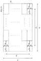
図1に、実施形態に係る眼科装置の概略構成を示す。実施形態に係る眼科装置1は、被検眼Eの眼底Efを光でスキャンすることによりデータを収集し、収集されたデータに基づいて眼底Efの画像を取得する。図1では、眼底Efの断層像又は3次元画像、正面画像などが得られる。<Composition>
FIG. 1 shows a schematic configuration of an ophthalmic apparatus according to an embodiment. The
眼科装置1は、光学系2と、光学系2を収容する収容部3と、移動機構4と、制御部5と、画像形成部6と、データ処理部7と、ユーザインターフェイス(UI)部8とを含む。眼科装置1には、制御部5からの制御を受けて移動機構4を駆動する駆動部4Dが設けられていてもよい。 The
<移動機構>
移動機構4は、光学系2(収容部3)を移動する。移動機構4は、xyz移動機構4Aと、スイング機構4Bと、チルト機構4Cとを含む。xyz移動機構4Aは、光学系2をx方向、y方向、及びz方向に移動する。スイング機構4Bは、被検眼Eの所定位置(例えば、瞳位置)を基準に光学系2を水平方向に旋回(回動)させる。具体的には、スイング機構4Bは、弧状の軌道に沿って光学系2を水平方向に移動させる。スイング機構4Bは、所定の移動角度範囲内において光学系2を旋回させる。チルト機構4Cは、被検眼Eの所定位置(例えば、瞳位置)を基準に光学系2を垂直方向に旋回(回動)させる。具体的には、チルト機構4Cは、弧状の軌道に沿って光学系2を垂直方向に移動させる。チルト機構4Cは、所定の移動角度範囲内において光学系2を旋回させる。旋回中心は、瞳位置に限定されず、後眼部のスキャンを妨げない範囲において瞳位置から変位した位置であってもよい。このような範囲内の位置を「瞳位置の近傍位置」と呼ぶ。なお、瞳位置に対する近傍位置の変位は、xyz空間における任意方向への変位であってよい。以下、特に言及しない限り、「瞳位置」は「瞳位置又はその近傍位置」を意味する。<Movement mechanism>
The moving mechanism 4 moves the optical system 2 (accommodation unit 3). The moving mechanism 4 includes an xyz moving mechanism 4A, a
xyz移動機構4Aは、例えば、被検眼Eに対する光学系2の位置合わせ(アライメント)やトラッキングにおいて用いられる。トラッキングとは、被検眼Eの運動に合わせて光学系2を移動させるものである。トラッキングを行う場合には、事前にアライメントとピント合わせが実行される。トラッキングは、被検眼Eを撮影(動画撮影)して得られる画像に基づき被検眼Eの位置や向きに合わせて光学系2をリアルタイムで移動させることにより、アライメントとピントが合った好適な位置関係を維持する機能である。 The xyz movement mechanism 4A is used, for example, in the alignment and tracking of the optical system 2 with respect to the eye E to be inspected. The tracking is to move the optical system 2 according to the movement of the eye E to be inspected. When performing tracking, alignment and focusing are performed in advance. Tracking is a suitable positional relationship in which alignment and focus are achieved by moving the optical system 2 in real time according to the position and orientation of the eye E to be inspected based on an image obtained by photographing the eye E to be inspected (moving a moving image). It is a function to maintain.
スイング機構4B及びチルト機構4Cは、被検眼E(眼底Ef)に対する広範囲のスキャンや眼底Efの周辺部の撮影に用いられる。スイング機構4B及びチルト機構4Cは、例えば、瞳位置を中心に光学系2を所定の移動角度範囲内で3次元的に旋回させる。 The
このような移動機構4は、例えば、光学系2を保持する1以上の保持部材と、上記移動角度範囲内の任意の位置に移動可能に設けられた1以上のガイドアームとを含む。移動機構4は、ガイドアームに沿ってスライドする。なお、旋回方向の次元は3次元には限定されず、例えば1次元又は2次元であってもよい。 Such a moving mechanism 4 includes, for example, one or more holding members for holding the optical system 2 and one or more guide arms movably provided at an arbitrary position within the moving angle range. The moving mechanism 4 slides along the guide arm. The dimension in the turning direction is not limited to three dimensions, and may be, for example, one dimension or two dimensions.
駆動部4Dは、例えば、制御部5の制御の下に動作する。この場合、駆動部4Dは、光学系2を旋回するための駆動力を発生するアクチュエーターを含む(図示省略)。アクチュエーターは、制御部5からの制御信号に応じた駆動力を発生する。この駆動力は、図示しない伝達機構により伝達され、保持部材をガイドアームに沿って移動する。このような制御により、当該制御信号に応じた方向に、当該制御信号に応じた角度だけ、光学系2が旋回される。この場合、光学系2の位置は、制御部5による駆動部4Dに対する制御内容により特定される。特定された位置情報(移動情報)は、例えば、制御部5、画像形成部6、データ処理部7などによって利用される。 The
また、移動機構4は、アクチュエーターを備えていなくてよい。この場合、光学系2が手動で旋回される。光学系2の位置は、エンコーダーや位置センサーによって検知される。これにより取得された位置情報は、例えば、制御部5、画像形成部6、データ処理部7などによって利用される。 Further, the moving mechanism 4 does not have to include an actuator. In this case, the optical system 2 is manually swiveled. The position of the optical system 2 is detected by an encoder or a position sensor. The position information acquired in this way is used by, for example, the control unit 5, the
いくつかの実施形態では、移動機構4は、収容部3を移動することにより光学系2を移動させる。いくつかの実施形態では、移動機構4は、光学系2の一部だけを移動させる。 In some embodiments, the moving mechanism 4 moves the optical system 2 by moving the accommodating portion 3. In some embodiments, the moving mechanism 4 moves only a portion of the optical system 2.
<光学系>
光学系2は、眼底Efのデータを光学的に収集するための光学部材や機構を含む。光学系2は、照明光学系10と、観察光学系20と、走査光学系30と、干渉光学系40と、固視光学系50とを含む。いくつかの実施形態では、光学系2は、被検眼Eに対する光学系2のアライメントを行うためのアライメント系、及び被検眼Eに対する光学系2のフォーカシングを行うためのフォーカス系のうちの少なくとも1つを含む。<Optical system>
The optical system 2 includes an optical member and a mechanism for optically collecting data of the fundus Ef. The optical system 2 includes an illumination
光学系2は、上記の光学系の光路を分離したり他の光学系と結合したりするための光路結合分離部材としての光学素子を含む。図1では、光路結合分離部材として、例えば、ビームスプリッタM1〜M3が設けられている。 The optical system 2 includes an optical element as an optical path coupling separation member for separating the optical path of the above optical system or coupling it with another optical system. In FIG. 1, beam splitters M1 to M3 are provided as optical path coupling separating members, for example.
ビームスプリッタM1は、照明光学系10の光路と観察光学系20の光路とを結合したり、ビームスプリッタM2を透過した光の光路から観察光学系20の光路を分離したりする。 The beam splitter M1 combines the optical path of the illumination
ビームスプリッタM1は、照明光学系10からの光を透過し、ビームスプリッタM2を透過した光を観察光学系20に向けて反射する特性を有する。ビームスプリッタM1は、照明光学系10の光軸が観察光学系20の光軸と略同軸になるように、これら光学系を結合することが望ましい。 The beam splitter M1 has a property of transmitting light from the illumination
ビームスプリッタM2は、走査光学系30(又は干渉光学系40)の光路と照明光学系10(又は観察光学系20)の光路とを結合したり、ビームスプリッタM3により反射された光の光路から走査光学系30(又は干渉光学系40)の光路と照明光学系10(又は観察光学系20)の光路とを分離したりする。ビームスプリッタM2は、ビームスプリッタM1からの光を透過し、走査光学系30からの光をビームスプリッタM3に向けて反射し、走査光学系30からの光の被検眼Eからの戻り光を走査光学系30に向けて反射し、照明光学系10からの光の被検眼Eからの戻り光を透過する特性を有する。ビームスプリッタM2は、走査光学系30(又は干渉光学系40)の光軸が照明光学系10(又は観察光学系20)の光軸と略同軸になるように、これら光学系を結合することが望ましい。 The beam splitter M2 combines the optical path of the scanning optical system 30 (or the interfering optical system 40) with the optical path of the illumination optical system 10 (or the observation optical system 20), or scans from the optical path of the light reflected by the beam splitter M3. The optical path of the optical system 30 (or the interference optical system 40) and the optical path of the illumination optical system 10 (or the observation optical system 20) are separated. The beam splitter M2 transmits the light from the beam splitter M1, reflects the light from the scanning
ビームスプリッタM3は、固視光学系50の光路とそれ以外の光学系の光路とを結合する。ビームスプリッタM3は、固視光学系50からの光を透過し、それ以外の光学系(照明光学系10や干渉光学系40)からの光又はその戻り光を反射する特性を有する。ビームスプリッタM3は、固視光学系50の光軸がそれ以外の光学系の光軸と略同軸になるように、これら光学系を結合することが望ましい。 The beam splitter M3 combines the optical path of the optometry
図1では図示が省略されているが、ビームスプリッタM3と被検眼Eとの間には対物レンズが配置されている。 Although not shown in FIG. 1, an objective lens is arranged between the beam splitter M3 and the eye E to be inspected.
(照明光学系)
照明光学系10は、被検眼Eの前眼部を照明する。照明光学系10は、照明光源やレンズなどを含む。(Illumination optical system)
The illumination
(観察光学系)
観察光学系20は、照明光学系10により照明されている被検眼Eの前眼部を観察するために用いられる。観察光学系20は、接眼レンズ及び撮像素子の少なくとも一方を含む。接眼レンズは、被検眼Eの肉眼観察に用いられる。撮像素子は、被検眼Eの正面画像の取得に用いられる。(Observation optical system)
The observation
照明光学系10からの照明光は、ビームスプリッタM1、M2を透過し、ビームスプリッタM3により反射され、図示しない対物レンズを通過して被検眼Eの前眼部を照明する。被検眼Eからの照明光の戻り光は、同じ経路を逆方向に進行し、ビームスプリッタM1により反射され、観察光学系20に入射する。観察光学系20に入射した戻り光は、例えば、撮像素子の撮像面に集光される。撮像素子を用いて取得された画像は、撮像素子からの信号を受けた制御部5がUI部8を制御することによって図示しない表示デバイスに表示される。 The illumination light from the illumination
(走査光学系)
走査光学系30は、制御部5からの制御を受け、干渉光学系40から出力された測定光を偏向する。例えば、走査光学系30は、2次元的な偏向角度範囲内において光を偏向する。なお、偏向方向の次元は2次元には限定されず、例えば1次元であってもよい。(Scanning optical system)
The scanning
走査光学系30は、光スキャナーを含む。光スキャナーとしては、1軸の偏向部材又は互いに直交する2軸の偏向部材が用いられる。偏向部材の例として、ガルバノミラー、ポリゴンミラー、回転ミラー、ダボプリズム、ダブルダボプリズム、ローテーションプリズム、MEMSミラースキャナーなどがある。2軸の偏向部材が用いられる場合、高速スキャン用の偏向部材(例えばポリゴンミラー)と低速スキャン用の偏向部材(例えばガルバノミラー)とを組み合わせることができる。走査光学系30は、偏向された光を眼底Efに投射するための光学素子を更に含んでもよい。 The scanning
光スキャナーは、被検眼Eの瞳孔と光学的に略共役な位置又はその近傍に配置される。それにより、被検眼Eの瞳孔(又はその近傍)をスキャン中心位置として、当該スキャン中心位置を中心に偏向された測定光で被検眼Eの眼内がスキャンされる。 The optical scanner is arranged at or near a position optically substantially conjugated with the pupil of the eye E to be inspected. As a result, the inside of the eye of the eye E to be inspected is scanned with the measurement light deflected around the center position of the scan with the pupil of the eye E to be inspected (or its vicinity) as the scan center position.
(干渉光学系)
干渉光学系40は、光源からの光を測定光と参照光とに分割し、測定光を被検眼E(眼底Ef)に照射し、被検眼Eからの測定光の戻り光と参照光とを重ね合わせて得られる干渉光を検出器に導く。干渉光学系40は、例えばスウェプトソースタイプ又はスペクトラルドメインタイプのOCT(Optical Coherence Tomography)が適用される。(Interference optical system)
The interference
スウェプトソースタイプのOCTが適用される場合、干渉光学系40は、出射光の波長を掃引(走査)可能な波長掃引型(波長走査型)光源であるOCT光源を含む。波長掃引型光源には、例えば、共振器を含み、所定の中心波長を有する光を発するレーザー光源が用いられる。波長掃引型光源は、人眼では視認できない近赤外の波長帯において、出力波長を時間的に変化させる。 When a swept source type OCT is applied, the interference
OCT光源から出力される光は、例えば、1040〜1060nm程度(例えば、1050nm)の中心波長を有し、50nm程度の波長幅を有する近赤外光であってよい。なお、この実施形態では特にスウェプトソースタイプについて説明しているが、スペクトラルドメインタイプを適用する場合には、スーパールミネセントダイオード(Super Luminescent Diode:SLD)や、LEDや、SOA(Semiconductor Optical Amplifier)等の光出力デバイスが光源として用いられる。一般に、OCT光源の構成としては、OCTのタイプに応じたものが適宜選択される。 The light output from the OCT light source may be, for example, near-infrared light having a center wavelength of about 1040 to 160 nm (for example, 1050 nm) and a wavelength width of about 50 nm. In this embodiment, the swept source type is particularly described, but when the spectral domain type is applied, a super luminescent diode (SLD), an LED, an SOA (Semiconductor Optical Amplifier), or the like is used. The light output device of is used as a light source. In general, the configuration of the OCT light source is appropriately selected according to the type of OCT.
OCT光源から出力された光は、光ファイバによりファイバカプラに導かれて測定光と参照光とに分割される。測定光は、光ファイバにより導光され、ファイバ端部から出射され、コリメートレンズにより平行光束となる。この光ファイバのファイバ端部は、被検眼Eの眼底Efと光学的に略共役な位置である眼底共役位置又はその近傍に配置されている。測定光は、走査光学系30により偏向され、ビームスプリッタM2により反射され、ビームスプリッタM3により被検眼Eに向けて反射される。眼底Efに照射された測定光は、例えば、眼底Efなどの測定部位において散乱、反射される。この散乱光及び反射光をまとめて測定光の戻り光と称することがある。測定光の戻り光は、同じ経路を逆向きに進行して上記のファイバカプラに導かれる。 The light output from the OCT light source is guided by an optical fiber to a fiber coupler and divided into measurement light and reference light. The measurement light is guided by an optical fiber, emitted from the end of the fiber, and becomes a parallel luminous flux by a collimating lens. The fiber end of the optical fiber is arranged at or near the fundus conjugate position, which is a position optically conjugated to the fundus Ef of the eye E to be inspected. The measurement light is deflected by the scanning
一方、参照光は、光ファイバにより導光され、参照光の光路に沿って移動可能な参照ミラーにより反射され、その反射光は再び上記のファイバカプラに導かれる。なお、参照光の光路には、偏波コントローラ(偏波調整器)や、分散補償用の光学素子(ペアプリズム等)や、偏光補正用の光学素子(波長板等)や、制御部5の制御の下で光ファイバを通過している参照光の光量を調整する光減衰器(アッテネータ)が設けられていてもよい。偏波コントローラは、例えば、ループ状にされた光ファイバに対して外部から応力を与えることで、当該光ファイバ内を通過している参照光の偏波(偏光)状態を調整する。 On the other hand, the reference light is guided by an optical fiber, reflected by a reference mirror that can move along the optical path of the reference light, and the reflected light is again guided to the above-mentioned fiber coupler. In the optical path of the reference light, a polarization controller (polarization adjuster), an optical element for dispersion compensation (pair prism, etc.), an optical element for polarization correction (wave plate, etc.), and a control unit 5 are used. An optical attenuator may be provided to adjust the amount of reference light passing through the optical fiber under control. The polarization controller adjusts the polarization state of the reference light passing through the optical fiber by, for example, applying stress to the looped optical fiber from the outside.
参照光の光路、及び測定光の光路の少なくとも一方には、光路長変更部が設けられている。光路長変更部は、参照光の光路長に対する測定光の光路長を相対的に変更する。この光路長の変更は、眼軸長に応じた光路長補正や、干渉状態の調整などに利用される。このような光路長変更部は、例えば、コーナーキューブと、制御部5からの指示を受けて入射光の光路に沿ってコーナーキューブを移動する機構とを含む。 An optical path length changing portion is provided in at least one of the optical path of the reference light and the optical path of the measurement light. The optical path length changing unit changes the optical path length of the measured light relative to the optical path length of the reference light. This change in the optical path length is used for correcting the optical path length according to the axial length and adjusting the interference state. Such an optical path length changing unit includes, for example, a corner cube and a mechanism for moving the corner cube along the optical path of incident light in response to an instruction from the control unit 5.
測定光の戻り光と参照ミラーにより反射された参照光が入射する上記のファイバカプラは、測定光の戻り光と参照光とを合波する。これにより生成された干渉光は、光ファイバにより検出器に導光される。このとき、別のファイバカプラにより所定の分岐比(例えば1:1)で干渉光を分岐して一対の干渉光が生成される。一対の干渉光は、検出器(バランスドフォトダイオード)により検出される。なお、スペクトラルドメインOCTの場合、検出器(分光器)は、ファイバカプラにより生成された干渉光を複数の波長成分に分解して検出する。 The above-mentioned fiber coupler, in which the return light of the measurement light and the reference light reflected by the reference mirror are incident, combines the return light of the measurement light and the reference light. The interference light generated thereby is guided to the detector by an optical fiber. At this time, another fiber coupler branches the interference light at a predetermined branching ratio (for example, 1: 1) to generate a pair of interference lights. The pair of interference lights is detected by a detector (balanced photodiode). In the case of spectral domain OCT, the detector (spectrometer) decomposes the interference light generated by the fiber coupler into a plurality of wavelength components and detects them.
検出器は、一対の干渉光を検出した結果(検出信号)を図示しないDAQ(Data Acquisition System)に送る。DAQには、OCT光源からクロックが供給される。このクロックは、波長可変光源により所定の波長範囲内にて掃引される各波長の出力タイミングに同期して生成される。DAQは、このクロックに基づいて検出信号をサンプリングする。サンプリング結果は、OCT画像を形成するための画像形成部6に送られる。 The detector sends the result of detecting the pair of interference lights (detection signal) to a DATA (Data Acquisition System) (not shown). A clock is supplied to the DAC from the OCT light source. This clock is generated in synchronization with the output timing of each wavelength swept within a predetermined wavelength range by a tunable light source. The DAQ samples the detection signal based on this clock. The sampling result is sent to the
(固視光学系)
固視光学系50は、被検眼Eの眼底Efに固視光束を投射する。固視光学系50は、制御部5からの制御を受け、被検眼Eの眼底Efにおける固視光束の投射位置を変更可能に構成される。(Optometry optical system)
The fixation
このような固視光学系50は、制御部5からの指示を受けて視標パターンを表示する液晶ディスプレイなどの表示デバイスを含む。表示デバイスは、視標パターンの表示位置を変更することにより、眼底Efにおける固視光束の投射位置を変更することができる。いくつかの実施形態では、固視光学系50は、複数の固視光源を含み、制御部5からの指示を受けて複数の固視光源を選択的に点灯させる。この場合、固視光学系50は、複数の固視光源の中で点灯させる固視光源を変更することにより、眼底Efにおける固視光束の投射位置を変更することができる。複数の固視光源のそれぞれは、可視光を出力する可視光源である。いくつかの実施形態では、眼科装置1には、複数の外部固視光源が設けられてもよい。複数の外部固視光源は、被検眼Eの僚眼に固視光を投射することが可能である。僚眼における固視光の投射位置は、変更可能である。僚眼に対する固視光の投射位置を変更することにより、被検眼Eの固視位置を変更することができる。例えば、複数の外部固視光源を選択的に点灯させることにより、移動可能な固視標を生成することができる。いくつかの実施形態では、移動可能な1以上の外部固視光源により、移動可能な固視標が生成される。 Such an optometry
上記のように、光学系2には、アライメント系やフォーカス系が設けられていてもよい。アライメント系やフォーカス系についても、従来と同様に、指標(アライメント指標、フォーカシング指標)を被検眼Eに投影するための光学系と、その戻り光を検出するための光学系とを含む。なお、被検眼Eの前眼部を撮影する2以上の撮像装置を設け、これら撮像装置により実質的に同時に取得された2以上の前眼部像を解析して(例えば三角法を利用して)アライメントを行うように構成することもできる。 As described above, the optical system 2 may be provided with an alignment system or a focus system. The alignment system and the focus system also include an optical system for projecting an index (alignment index, focusing index) onto the eye E to be inspected, and an optical system for detecting the return light thereof, as in the conventional case. It should be noted that two or more imaging devices for photographing the anterior segment of the eye E to be inspected are provided, and two or more anterior segment images acquired substantially simultaneously by these imaging devices are analyzed (for example, by using the trigonometry). ) It can also be configured to perform alignment.
<スキャンについて>
光学系2において、例えば、干渉光学系40におけるOCT光源から生成された測定光は、走査光学系30により偏向され、被検眼Eの瞳孔を通じて眼底Efにスポット光として結像される。その戻り光は、スポット光の投射位置(及びその近傍位置)から光学系2に戻ってくる光である。戻り光は、上記したようにファイバカプラに導かれ、参照光と合波される。測定光の戻り光と参照光との干渉光は、検出器により検出される。検出器は、光電変換により電気信号(受光信号)を生成する。なお、スポット光の投射位置をスポット位置と記載することがある。<About scanning>
In the optical system 2, for example, the measurement light generated from the OCT light source in the interference
この一連のプロセスは、眼底Efの一点の計測に相当する。走査光学系30は、所定の偏向角度範囲内においてスポット位置を移動する。つまり、走査光学系30により、所定の偏向角度範囲内におけるスキャンが実現される。また、移動機構4は、所定の移動角度範囲内において光学系2を旋回する。つまり、移動機構4は、走査光学系30の偏向角度範囲に対応するスキャンエリア(単一スキャンエリア)を移動する。これらを組み合わせることで、単一スキャンエリアを移動させつつ眼底Efの広い範囲を計測することができる。 This series of processes corresponds to the measurement of one point of the fundus Ef. The scanning
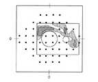
図2に、実施形態に係る眼科装置1によるスキャン動作の説明図を示す。 FIG. 2 shows an explanatory diagram of a scanning operation by the
図2に示すように、全スキャンエリアTAは、1以上のサブスキャンエリアSA(α,β)を含む。全スキャンエリアTAの水平方向(例えばx方向)の広がりをθHとし、垂直方向(例えばy方向)の広がりをθVとする。全スキャンエリアTAは、縦横に配列された複数のサブスキャンエリアSA(α,β)に分割されている。ここで、α=1,2,・・・,J、且つ、β=1,2,・・・,Kであり、J及びKはそれぞれ1以上の整数であり、J及びKの少なくとも一方は2以上の整数である。なお、複数のサブスキャンエリアSA(α,β)の全てが同じサイズである必要もなく、また、同じ形状である必要もない。As shown in FIG. 2, the entire scan area TA includes one or more sub-scan areas SA (α, β). Let θH be the spread in the horizontal direction (for example, x direction) of the entire scan area TA, and let θV be the spread in the vertical direction (for example, y direction). The entire scan area TA is divided into a plurality of sub-scan areas SA (α, β) arranged vertically and horizontally. Here, α = 1,2, ···, J, and β = 1, 2, ···, K, J and K are integers of 1 or more, respectively, and at least one of J and K is It is an integer of 2 or more. It is not necessary that all of the plurality of sub-scan areas SA (α, β) have the same size and the same shape.
各サブスキャンエリアSA(α,β)は単一スキャンエリアに相当する。サブスキャンエリアSA(α,β)の一部とサブスキャンエリアSA(α+1,β)の一部とが重複していてもよく、サブスキャンエリアSA(α,β)の一部とサブスキャンエリアSA(α,β+1)の一部とが重複していてもよい。 Each sub-scan area SA (α, β) corresponds to a single scan area. A part of the sub-scan area SA (α, β) and a part of the sub-scan area SA (α + 1, β) may overlap, and a part of the sub-scan area SA (α, β) and the sub-scan area may overlap. A part of SA (α, β + 1) may overlap.
実施形態では、複数のサブスキャンエリアSA(α,β)を順次にスキャンすることにより全スキャンエリアTAのスキャンが実現される。走査光学系30を制御することにより各サブスキャンエリアSA(α,β)のスキャンが実行され、移動機構4の制御によりスキャン対象となるサブスキャンエリアSA(α,β)が切り替えられる。 In the embodiment, scanning of the entire scan area TA is realized by sequentially scanning a plurality of sub-scan areas SA (α, β). By controlling the scanning
各サブスキャンエリアSA(α,β)のスキャンについて説明する。例えば、走査光学系30は、干渉光学系40からの測定光を所定の偏向角度範囲内において偏向する。この偏向角度範囲の水平方向の広がりを「2・θH1」とし、垂直方向の広がりを「2・θV1」とする。つまり、走査光学系30は、その偏向中心(例えば走査光学系30の光軸上の位置)を基準に、左右方向にそれぞれ「θH1」だけスポット位置を移動することができ、上下方向にそれぞれ「θV1」だけスポット位置を移動することができる。なお、偏向角度とxy面内の距離(弦の長さ)とは互いに対応しているので、これらを同一視することができる。Scanning of each sub-scan area SA (α, β) will be described. For example, the scanning
移動機構4により瞳位置を中心に所定の移動角度範囲内において光学系2を旋回させることにより、サブスキャンエリアSA(α,β)が切り替えられる。この移動角度範囲の水平方向の広がりを「θH2」とし、垂直方向の広がりを「θV2」とする。つまり、移動機構4は、水平方向に「θH2」だけ光学系2を旋回することができ、垂直方向に「θV2」だけ光学系2を旋回することができる。The sub-scan area SA (α, β) is switched by rotating the optical system 2 within a predetermined movement angle range around the pupil position by the movement mechanism 4. The horizontal spread of this movement angle range is "θH2 ", and the vertical spread is "θV2 ". That is, the moving mechanism 4 can rotate the optical system 2 by "θH2 " in the horizontal direction, and can rotate the optical system 2 by "θV2 " in the vertical direction.
このような走査光学系30と移動機構4によれば、複数のサブスキャンエリアSA(α,β)が重複も隙間もなく配置されている場合、スポット位置の水平方向の移動範囲はθH=θH2+2×θH1であり、垂直方向の移動範囲はθV=θV2+2×θV1である。水平方向の広がりがθHであり、且つ、垂直方向の広がりがθVであるエリアは、全スキャンエリアTAに相当する。なお、重複や隙間が設けられる場合には、重複の幅や隙間の間隔に応じて全スキャンエリアTAが決定される。According to the scanning
一例において、θH1=60度、θH2=40度、θV1=40度、θV2=40度に設定される。それにより、水平方向に160度、且つ、垂直方向に120度の範囲をスキャンすることが可能となる。なお、θH1、θH2、θV1、θV2は、例えば、コストや作動距離などの任意のファクタを考慮して決定される。In one example, θH1 = 60 degrees, θH2 = 40 degrees, θV1 = 40 degrees, and θV2 = 40 degrees. As a result, it is possible to scan a range of 160 degrees in the horizontal direction and 120 degrees in the vertical direction. Note that θH1 , θH2 , θV1 , and θV2 are determined in consideration of arbitrary factors such as cost and working distance.
<制御部>
制御部5は、装置各部の制御を行う。制御部5は、プロセッサ及び記憶装置(記憶回路)を含む。記憶装置には、眼科装置1を制御するためのコンピュータプログラムが予め格納される。このコンピュータプログラムには、光源制御用プログラム、走査制御用プログラム、移動機構制御用プログラム、画像形成制御用プログラム、データ処理制御用プログラム、ユーザインターフェイス制御用プログラムなどが含まれる。このようなコンピュータプログラムに従ってプロセッサが動作することにより、制御部5は制御処理を実行する。<Control unit>
The control unit 5 controls each unit of the device. The control unit 5 includes a processor and a storage device (storage circuit). A computer program for controlling the
制御部5は、主制御部51と、記憶部52とを含む。 The control unit 5 includes a main control unit 51 and a storage unit 52.
(主制御部)
主制御部51は、プロセッサを含み、眼科装置1の各部を制御する。例えば、主制御部51は、光学系2、移動機構4(駆動部4D)、画像形成部6、データ処理部7、及びUI部8などを制御する。(Main control unit)
The main control unit 51 includes a processor and controls each unit of the
光学系2に対する制御には、図示しない合焦レンズを移動する合焦駆動部の制御、イメージセンサ等の撮像素子の制御、光スキャナーの制御、光路長変更部の制御、光減衰器の制御、偏波コントローラの制御、固視光学系50(表示デバイス)の制御などがある。いくつかの実施形態では、合焦レンズは、走査光学系30とビームスプリッタM2との間に配置される。いくつかの実施形態では、合焦レンズは、観察光学系20に含まれる。 Controls for the optical system 2 include control of a focusing drive unit that moves a focusing lens (not shown), control of an image sensor such as an image sensor, control of an optical scanner, control of an optical path length changing unit, and control of an optical attenuator. There are control of the polarization controller, control of the optometry optical system 50 (display device), and the like. In some embodiments, the focusing lens is placed between the scanning
移動機構4に対する制御には、xyz移動機構4Aを駆動する駆動部の制御、スイング機構4Bを駆動する駆動部の制御、及びチルト機構4Cを駆動する駆動部の制御などがある。 The control for the moving mechanism 4 includes the control of the driving unit that drives the xyz moving mechanism 4A, the control of the driving unit that drives the
マニュアルアライメントの場合、光学系に対する被検眼Eの変位がキャンセルされるようにユーザが後述のUI部8に対して操作することにより光学系と被検眼Eとを相対移動させる。例えば、主制御部51は、UI部8に対する操作内容に対応した制御信号をxyz移動機構4A(駆動部4D)に出力することによりxyz移動機構4Aを制御して光学系2と被検眼Eとを相対移動させる。 In the case of manual alignment, the user operates the
オートアライメントの場合、光学系に対する被検眼Eの変位がキャンセルされるように主制御部51がxyz移動機構4Aを制御することにより光学系と被検眼Eとを相対移動させる。いくつかの実施形態では、主制御部51は、光学系2の測定光軸Oが被検眼Eの軸に略一致し、かつ、被検眼Eに対する光学系の距離が所定の作動距離になるように制御信号をxyz移動機構4A(駆動部4D)に出力することによりxyz移動機構4Aを制御して光学系2と被検眼Eとを相対移動させる。ここで、作動距離とは、図示しない対物レンズのワーキングディスタンスとも呼ばれる既定値であり、光学系を用いた測定時(撮影時)における被検眼Eと光学系2との間の距離に相当する。 In the case of auto-alignment, the main control unit 51 controls the xyz movement mechanism 4A so that the displacement of the eye E to be inspected with respect to the optical system is canceled, so that the optical system and the eye E to be inspected are relatively moved. In some embodiments, the main control unit 51 ensures that the measurement optical axis O of the optical system 2 substantially coincides with the axis of the eye E to be inspected, and that the distance of the optical system to the eye E to be inspected is a predetermined working distance. By outputting a control signal to the xyz movement mechanism 4A (drive
また、走査光学系30と移動機構4とを連係的に制御することで、図2に例示するようなスキャンを実現することができる。例えば、主制御部51の記憶装置(記憶部52)には、測定光を偏向するための既定の偏向パターンと、光学系2を移動させるための既定の移動パターンとが予め記憶されている。偏向パターンや移動パターンは、デフォルト設定されてもよいし、ユーザにより設定されてもよい。また、複数の偏向パターンと複数の移動パターンとを任意に組み合わせて適用できるように構成してもよい。パターンの選択は、例えばユーザ又は主制御部51により行われる。 Further, by controlling the scanning
主制御部51は、偏向パターンに基づく走査光学系30の制御(走査制御)と、移動パターンに基づく移動機構4の制御(移動制御)とを連係的に実行する。例えば、主制御部51は、走査制御と移動制御とを交互に実行する。ここで、単一の走査制御は、単一スキャンエリア(1つのサブスキャンエリア)のスキャンに相当し、単一の移動制御は、サブスキャンエリアの切り替えに相当する。他の例として、主制御部51は、全スキャンエリアに対するスキャンの少なくとも一部のフェーズにおいて走査制御と移動制御とを並行して行うことができる。 The main control unit 51 sequentially executes the control of the scanning
図3に、実施形態に係るスキャンモードの説明図を示す。図3は、視神経乳頭Nと黄斑部Hとを含む全スキャンエリアARを複数のサブスキャンエリアに分けて走査する態様を模式的に表している。 FIG. 3 shows an explanatory diagram of the scan mode according to the embodiment. FIG. 3 schematically shows a mode in which the entire scan area AR including the optic disc N and the macula H is divided into a plurality of sub-scan areas and scanned.
主制御部51は、既定の移動パターンに従って移動機構4を制御することにより、スキャン対象となるサブスキャンエリア(単一スキャンエリア)を、例えばサブスキャンエリアSR1、SR2、SR3、・・・の順に移動させる。このとき、隣接するサブスキャンエリアSRi、SR(i+1)同士は重複エリアCRiを有する(i=1,2,3,・・・)。複数のサブスキャンエリアから得られた複数の画像から全スキャンエリアARの画像を形成するとき、重複エリアを利用して隣接する画像同士の位置合わせを行うことができる。主制御部51は、既定の偏向パターンに基づいて、各サブスキャンエリアのスキャンを行うように光学系2を制御する。図3に示す例ではラスタースキャンが適用される。偏向パターンの他の例として、サークルスキャン、同心円スキャン、ラジアルスキャン、スリットスキャン(1次元スキャン)などがある。 By controlling the movement mechanism 4 according to a predetermined movement pattern, the main control unit 51 sets the sub-scan area (single scan area) to be scanned, for example, in the order of sub-scan areas SR1, SR2, SR3, ... Move. At this time, the adjacent sub-scan areas SRi and SR (i + 1) have overlapping areas CRi (i = 1, 2, 3, ...). When forming an image of the entire scan area AR from a plurality of images obtained from a plurality of sub-scan areas, it is possible to align adjacent images by using the overlapping area. The main control unit 51 controls the optical system 2 so as to scan each sub-scan area based on a predetermined deflection pattern. In the example shown in FIG. 3, raster scan is applied. Other examples of the deflection pattern include a circle scan, a concentric circle scan, a radial scan, a slit scan (one-dimensional scan), and the like.
また、主制御部51は、OCT計測を行う前に複数の予備的な動作を実行可能である。予備的な動作としては、アライメント、フォーカス粗調整、偏光調整、フォーカス微調整などがある。複数の予備的な動作は、所定の順序で実行される。いくつかの実施形態では、複数の予備的な動作は、上記の順序で実行される。 Further, the main control unit 51 can execute a plurality of preliminary operations before performing the OCT measurement. Preliminary operations include alignment, coarse focus adjustment, polarization adjustment, and fine focus adjustment. The plurality of preliminary operations are performed in a predetermined order. In some embodiments, the plurality of preliminary operations are performed in the above order.
フォーカス粗調整は、スプリット指標を用いたフォーカス調整である。なお、あらかじめ取得された眼屈折力と観察光学系20に設けられた合焦レンズの位置とを関連付けた情報と、被検眼Eの屈折力の測定値とに基づいて当該合焦レンズの位置を決定することにより、フォーカス粗調整を行うこともできる。 The coarse focus adjustment is a focus adjustment using a split index. It should be noted that the position of the focusing lens is determined based on the information relating the eye refractive power acquired in advance and the position of the focusing lens provided in the observation
フォーカス微調整は、OCT計測の干渉感度に基づいて行われる。例えば、被検眼EのOCT計測により取得された干渉信号の干渉強度(干渉感度)をモニタすることにより、干渉強度が最大となるような合焦レンズ(走査光学系30とビームスプリッタM2との間に設けられた合焦レンズ)の位置を求め、その位置に当該合焦レンズを移動させることにより、フォーカス微調整を実行することができる。 The focus fine adjustment is performed based on the interference sensitivity of the OCT measurement. For example, by monitoring the interference intensity (interference sensitivity) of the interference signal acquired by the OCT measurement of the eye E to be inspected, the focusing lens (between the scanning
光路長差調整においては、被検眼Eにおける所定の位置が深さ方向の計測範囲の基準位置になるように制御される。この制御は、上記の光路長変更部に対して行われる。それにより、測定光路と参照光路との間の光路長差が調整される。光路長差調整により基準位置を設定しておくことで、波長掃引速度の変更を行うだけで深さ方向の所望の計測範囲に対して精度よくOCT計測を行うことができるようになる。 In the optical path length difference adjustment, the predetermined position in the eye E to be inspected is controlled so as to be the reference position of the measurement range in the depth direction. This control is performed on the above-mentioned optical path length changing unit. Thereby, the optical path length difference between the measurement optical path and the reference optical path is adjusted. By setting the reference position by adjusting the optical path length difference, it becomes possible to accurately perform OCT measurement with respect to a desired measurement range in the depth direction only by changing the wavelength sweep speed.
偏光調整においては、測定光と参照光との干渉効率を最適化するために参照光の偏波(偏光)状態が調整される。 In the polarization adjustment, the polarization state of the reference light is adjusted in order to optimize the interference efficiency between the measurement light and the reference light.
また、主制御部51は、表示制御部51Aを含む。表示制御部51Aは、UI部8の表示デバイス(表示部)又は図示しない外部の表示装置を制御することにより各種情報を表示させる。表示制御部51Aにより表示される情報として、光学系2の状態を表す情報、移動機構4の状態を表す情報、制御部5の制御内容又は制御結果を表す情報、画像形成部6により形成された画像、データ処理部7による処理結果、UI部8の操作デバイスに対する操作を補助するための情報などがある。 Further, the main control unit 51 includes a display control unit 51A. The display control unit 51A displays various information by controlling the display device (display unit) of the
(記憶部)
記憶部52は、各種のデータを記憶する。記憶部52に記憶されるデータとしては、例えば、OCT画像の画像データ、眼底像の画像データ、スキャンデータ、前眼部像の画像データ、被検眼情報などがある。被検眼情報は、患者IDや氏名などの被検者に関する情報や、左眼/右眼の識別情報などの被検眼に関する情報を含む。(Memory)
The storage unit 52 stores various types of data. Examples of the data stored in the storage unit 52 include image data of the OCT image, image data of the fundus image, scan data, image data of the anterior segment image, and eye information to be examined. The eye test information includes information about the subject such as the patient ID and name, and information about the test eye such as left eye / right eye identification information.
また、記憶部52には、眼球パラメータ52Aが記憶されている。眼球パラメータ52Aは、Gullstrand模型眼等の公知の眼球モデルで規定されたパラメータ(標準値)を含む。いくつかの実施形態では、眼球パラメータ52Aは、公知の眼球モデルで規定されたパラメータの少なくとも1つが被検眼Eの測定値に置き換えられたパラメータを含む。この場合、眼球パラメータ52Aは、被検眼Eの光学特性を表すパラメータを含むことを意味する。測定値には、眼軸長、角膜厚、角膜前面の曲率半径、角膜後面の曲率半径、前房深度、水晶体前面の曲率半径、水晶体厚、水晶体後面の曲率半径、硝子体腔長、網膜厚、脈絡膜厚などがある。いくつかの実施形態では、測定値は、OCT計測により得られたOCTデータを解析することにより取得される。眼球パラメータ52Aは、後述のUI部8により指定されたパラメータを含んでよい。 Further, the
また、記憶部52には、眼科装置1を動作させるための各種プログラムやデータが記憶されている。 In addition, various programs and data for operating the
<画像形成部>
画像形成部6は、被検眼Eにおける所定部位(例えば、瞳孔)と光学的に略共役に配置された光スキャナーを用いて測定光で眼内をスキャンすることにより得られたスキャンデータから被検眼EのOCT画像(断層像)を形成する。画像形成部6は、干渉光学系40における検出器からの検出信号をDAQでサンプリングすることにより得られたサンプリングデータに対してフーリエ変換等の信号処理を施すことによってAラインにおける反射強度プロファイルを形成する。上記信号処理には、ノイズ除去(ノイズ低減)、フィルタ処理、FFT(Fast Fourier Transform)などが含まれる。Aラインにおける反射強度プロファイルは、Aスキャンデータの一例である。画像形成部6は、Aライン毎に反射強度プロファイルを形成し、形成された複数の反射強度プロファイルをBスキャン方向(Aスキャン方向の交差方向)に配列することでBスキャンデータ(2次元のスキャンデータ)を形成することが可能である。<Image forming part>
The
いくつかの実施形態では、画像形成部6(又は後述のデータ処理部7)は、Aライン毎に形成された複数の反射強度プロファイルをBスキャン方向(例えば、x方向)と、Aスキャン方向及びBスキャン方向に交差する方向(例えば、y方向)とに配列することで3次元のスキャンデータを形成する。 In some embodiments, the image forming unit 6 (or the data processing unit 7 described later) performs a plurality of reflection intensity profiles formed for each A line in the B scan direction (for example, the x direction), the A scan direction, and the A scan direction. Three-dimensional scan data is formed by arranging the data in a direction intersecting the B scan direction (for example, the y direction).
また、画像形成部6は、Aラインにおける反射強度プロファイルを画像化することで、被検眼EのAスキャン画像(OCT画像、画像データ)を形成することが可能である。画像形成部6は、Aライン毎に形成された複数のAスキャン画像をBスキャン方向(Aスキャン方向の交差方向)に配列することでBスキャン画像を形成することが可能である。 Further, the
いくつかの実施形態では、画像形成部6は、各Aスキャンデータにおける所定の深さ位置(スキャン位置)のデータを抽出し、抽出された複数のデータをBスキャン方向(Aスキャン方向の交差方向)に配列することでCスキャンデータを形成する。いくつかの実施形態では、画像形成部6は、各Aスキャン画像における所定の深さ位置(スキャン位置)の画素を抽出し、抽出された複数の画素をBスキャン方向(Aスキャン方向の交差方向)に配列することでCスキャン画像を形成する。 In some embodiments, the
いくつかの実施形態では、画像形成部6の機能は、プロセッサにより実現される。なお、この明細書では、「画像データ」と、それに基づく「画像」とを同一視することがある。 In some embodiments, the function of the
<データ処理部7>
データ処理部7は、各種のデータ処理を実行する。データ処理の例として、画像形成部6又は他の装置により形成された画像データの処理がある。この処理の例として、画像処理、画像解析、画像評価、診断支援などがある。データ処理部7は、例えば、画像の輝度補正や分散補正等の補正処理を実行する。また、データ処理部7は、眼底像や断層像に対して各種の画像処理や解析処理を施す。データ処理部7は、断層像の間の画素を補間する補間処理などの公知の画像処理を実行することにより、被検眼Eのボリュームデータ(ボクセルデータ)を形成することができる。ボリュームデータに基づく画像を表示させる場合、データ処理部7は、このボリュームデータに対してレンダリング処理を施して、特定の視線方向から見たときの擬似的な3次元画像を形成する。<Data processing unit 7>
The data processing unit 7 executes various data processing. An example of data processing is the processing of image data formed by the
また、データ処理部7は、ボリュームデータからCモード画像、プロジェクション画像、シャドウグラムなどを形成することができる。Cモード画像は、例えば指定された断面上の画素(ピクセル、ボクセル)を3次元データセットから選択することにより形成される。プロジェクション画像は、3次元データセットを所定方向(Z方向、深さ方向、軸方向)に投影することによって形成される。シャドウグラムは、3次元データセットの一部(例えば特定層に相当する部分データ)を所定方向に投影することによって形成される。 In addition, the data processing unit 7 can form a C-mode image, a projection image, a shadow gram, or the like from the volume data. A C-mode image is formed, for example, by selecting pixels (pixels, voxels) on a specified cross section from a three-dimensional dataset. The projection image is formed by projecting a three-dimensional data set in a predetermined direction (Z direction, depth direction, axial direction). The shadow gram is formed by projecting a part of a three-dimensional data set (for example, partial data corresponding to a specific layer) in a predetermined direction.
更に、データ処理部7は、複数のサブスキャンエリアから得られた複数の画像(断層像)に対し、隣接する画像同士の位置合わせを行うことにより全スキャンエリアARの画像を生成することが可能である。このとき、データ処理部7は、重複エリアを利用して隣接する画像同士の位置合わせを行うことができる。 Further, the data processing unit 7 can generate an image of the entire scan area AR by aligning adjacent images with respect to a plurality of images (tomographic images) obtained from the plurality of sub scan areas. Is. At this time, the data processing unit 7 can align adjacent images with each other by using the overlapping area.
データ処理部7は、OCTにより時系列に収集されたデータ(例えば、Bスキャン画像データ)に基づいて、網膜血管や脈絡膜血管が強調されたBモード画像や正面画像(血管強調画像、アンギオグラム)を構築することができる。例えば、被検眼Eの略同一部位を反復的にスキャンすることにより、時系列のOCTデータを収集することができる。 The data processing unit 7 is a B-mode image or frontal image (blood vessel-enhanced image, angiogram) in which retinal blood vessels and choroidal blood vessels are emphasized based on data (for example, B-scan image data) collected in time series by OCT. Can be built. For example, time-series OCT data can be collected by repeatedly scanning substantially the same site of the eye E to be inspected.
いくつかの実施形態では、データ処理部7は、略同一部位に対するBスキャンにより得られた時系列のBスキャン画像を比較し、信号強度の変化部分の画素値を変化分に対応した画素値に変換することにより当該変化部分が強調された強調画像を構築する。更に、データ処理部7は、構築された複数の強調画像から所望の部位における所定の厚さ分の情報を抽出してen−face画像として構築することでOCTA像を形成する。 In some embodiments, the data processing unit 7 compares time-series B-scan images obtained by B-scanning on substantially the same part, and sets the pixel value of the signal strength change portion to the pixel value corresponding to the change. By converting, a emphasized image in which the changed part is emphasized is constructed. Further, the data processing unit 7 forms an OCTA image by extracting information having a predetermined thickness at a desired portion from the constructed plurality of emphasized images and constructing it as an en-face image.
更に、データ処理部7は、OCT計測により得られた干渉光の検出結果を解析してフォーカス微調整制御における測定光のフォーカス状態を判定する。例えば、主制御部51は、干渉光学系40の合焦レンズを所定のアルゴリズムにしたがって制御しつつ、反復的なOCT計測を行う。データ処理部7は、OCT計測により繰り返し取得される干渉光の検出結果を解析することで、OCT画像の画質に関する所定の評価値を算出する。データ処理部7は、算出された評価値が閾値以下であるか否か判定する。いくつかの実施形態では、フォーカス微調整は、算出される評価値が閾値以下になるまで継続される。すなわち、評価値が閾値以下であるとき測定光のフォーカス状態が適正であると判断され、フォーカス微調整は、測定光のフォーカス状態が適正であると判断されるまで継続される。 Further, the data processing unit 7 analyzes the detection result of the interference light obtained by the OCT measurement and determines the focus state of the measurement light in the focus fine adjustment control. For example, the main control unit 51 performs repetitive OCT measurement while controlling the focusing lens of the interference
いくつかの実施形態では、主制御部51は、上記のような反復的なOCT計測を行って干渉信号を取得しつつ、逐次に取得される干渉信号の強度(干渉強度、干渉感度)をモニタする。更に、このモニタ処理を行いながら、干渉光学系40の合焦レンズを移動させることにより、干渉強度が最大となるような合焦レンズの位置を探索する。このようなフォーカス微調整によれば、干渉強度が最適化されるような位置に合焦レンズを導くことができる。 In some embodiments, the main control unit 51 monitors the strength (interference intensity, interference sensitivity) of the interference signals that are sequentially acquired while performing the repetitive OCT measurement as described above to acquire the interference signal. To do. Further, while performing this monitor processing, the focusing lens of the interference
また、データ処理部7は、OCT計測により得られた干渉光の検出結果を解析して、測定光及び参照光の少なくとも一方の偏波状態を判定する。例えば、主制御部51は、偏波コントローラを所定のアルゴリズムにしたがって制御しつつ、反復的なOCT計測を行う。いくつかの実施形態では、主制御部51は、光減衰器を制御して、参照光の減衰量を変更する。データ処理部7は、OCT計測により繰り返し取得される干渉光の検出結果を解析することで、OCT画像の画質に関する所定の評価値を算出する。データ処理部7は、算出された評価値が閾値以下であるか否か判定する。この閾値はあらかじめ設定される。偏波調整は、算出される評価値が閾値以下になるまで継続される。すなわち、評価値が閾値以下であるとき測定光の偏波状態が適正であると判断され、偏波調整は、測定光の偏波状態が適正であると判断されるまで継続される。 Further, the data processing unit 7 analyzes the detection result of the interference light obtained by the OCT measurement and determines the polarization state of at least one of the measurement light and the reference light. For example, the main control unit 51 performs repetitive OCT measurement while controlling the polarization controller according to a predetermined algorithm. In some embodiments, the main control unit 51 controls the optical attenuator to change the amount of attenuation of the reference light. The data processing unit 7 calculates a predetermined evaluation value regarding the image quality of the OCT image by analyzing the detection result of the interference light repeatedly acquired by the OCT measurement. The data processing unit 7 determines whether or not the calculated evaluation value is equal to or less than the threshold value. This threshold is preset. The polarization adjustment is continued until the calculated evaluation value becomes equal to or less than the threshold value. That is, when the evaluation value is equal to or less than the threshold value, it is determined that the polarization state of the measurement light is appropriate, and the polarization adjustment is continued until it is determined that the polarization state of the measurement light is appropriate.
いくつかの実施形態では、主制御部51は、偏波調整においても干渉強度をモニタすることが可能である。 In some embodiments, the main control unit 51 can also monitor the interference strength in polarization adjustment.
更に、データ処理部7は、OCT計測により得られた干渉光の検出結果、又は当該検出結果に基づいて形成されたOCT画像に対して所定の解析処理を行う。所定の解析処理には、被検眼Eにおける所定の部位(組織、病変部)の特定;指定された部位間の距離(層間距離)、面積、角度、比率、密度の算出;指定された計算式による演算;所定の部位の形状の特定;これらの統計値の算出;計測値、統計値の分布の算出;これら解析処理結果に基づく画像処理などがある。所定の組織には、血管、視神経乳頭、中心窩、黄斑などがある。所定の病変部には、白斑、出血などがある。 Further, the data processing unit 7 performs a predetermined analysis process on the detection result of the interference light obtained by the OCT measurement or the OCT image formed based on the detection result. In the predetermined analysis process, the predetermined site (tissue, lesion) in the eye E to be examined is specified; the distance between the designated sites (interlayer distance), the area, the angle, the ratio, and the density are calculated; the designated formula is used. Calculation by; Identification of the shape of a predetermined part; Calculation of these statistical values; Calculation of the distribution of measured values and statistical values; Image processing based on these analysis processing results and the like. Predetermined tissues include blood vessels, optic discs, fovea centralis, macula and the like. Predetermined lesions include vitiligo, bleeding, and the like.
いくつかの実施形態では、データ処理部7は、取得されたOCT画像(断層像、スキャンデータ)における眼内の部位が実際の形状で描出されるように、OCT画像における画素位置又はスキャンデータにおけるスキャン位置の座標変換を行う。 In some embodiments, the data processor 7 in the pixel position or scan data in the OCT image so that the portion of the eye in the acquired OCT image (tomographic image, scan data) is depicted in its actual shape. Perform coordinate conversion of the scan position.
ここで、実施形態の比較例について説明する。 Here, a comparative example of the embodiment will be described.
図4及び図5に、実施形態の比較例の説明図を示す。図4は、被検眼Eに入射する測定光の経路を模式的に表したものである。図5は、図4に示す経路で被検眼Eに入射する測定光によるスキャンにより得られた断層像の一例を表したものである。 4 and 5 show explanatory views of comparative examples of the embodiments. FIG. 4 schematically shows the path of the measurement light incident on the eye E to be inspected. FIG. 5 shows an example of a tomographic image obtained by scanning with the measurement light incident on the eye E to be inspected by the path shown in FIG.
例えば走査光学系30の光スキャナーにより偏向された測定光は、図4に示すようにスキャン中心位置としての被検眼Eの瞳孔に対して様々な入射角度で入射する。被検眼Eに入射した測定光は、例えば瞳孔中心に設定されたスキャン中心位置Csを中心に眼内の各部に向けて投射される。 For example, the measurement light deflected by the optical scanner of the scanning
図4の測定光LS1を用いて得られた干渉データからAスキャン画像が形成され、測定光LS2を用いて得られた干渉データからAスキャン画像が形成され、測定光LS3を用いて得られた干渉データからAスキャン画像が形成される。図5に示す眼底の断層像IMG0は、このように形成された複数のAスキャン画像を配列することにより形成される。 An A scan image was formed from the interference data obtained by using the measurement light LS1 of FIG. 4, and an A scan image was formed from the interference data obtained by using the measurement light LS2, and was obtained by using the measurement light LS3. An A-scan image is formed from the interference data. The tomographic image IMG0 of the fundus shown in FIG. 5 is formed by arranging a plurality of A-scan images thus formed.
このように、スキャン中心位置Csを中心としたスキャン角度範囲内でAスキャン方向が変化し、得られた複数のAスキャン画像を横方向に配列された断層像において、部位の形状が変形する。これは、画角が広くなるほど、実際の形状との差異が大きくなる。 In this way, the A scan direction changes within the scan angle range centered on the scan center position Cs, and the shape of the portion is deformed in the tomographic image in which the obtained plurality of A scan images are arranged in the horizontal direction. This is because the wider the angle of view, the greater the difference from the actual shape.
また、被検眼Eの形態を表す形態情報は、断層像中の任意の画素の位置により求められる。このような形態情報には、眼内距離(層領域間の距離を含む)、領域の面積、領域の体積、領域の周囲長、基準位置に対する部位の方向、基準方向に対する部位の角度、部位の曲率半径などが挙げられる。 Further, morphological information representing the morphology of the eye E to be inspected is obtained from the position of an arbitrary pixel in the tomographic image. Such morphological information includes the intraocular distance (including the distance between layer regions), the area of the region, the volume of the region, the peripheral length of the region, the direction of the site with respect to the reference position, the angle of the site with respect to the reference direction, and the region. The radius of curvature and the like can be mentioned.
例えば、形態情報としての眼内距離は、断層像中の任意の2点間の距離を計測することで求めることが可能である。この場合、2点間の距離は、断層像中のピクセル数により特定され、特定されたピクセル数に装置固有のピクセルサイズを乗算することで計測される。このとき、断層像中の全ピクセルについて、同一のピクセルサイズが採用される。しかしながら、上記のように、スキャン中心位置Csを中心としてスキャン方向が異なるため、スキャン方向の深さ位置に応じて断層像の水平方向のピクセルサイズが異なる。例えば、深さ範囲が2.5[mm]の場合、断層像中の全ピクセルについて同一のピクセルサイズを採用したとき、断層像の上部と下部との間でBスキャンのスキャン長に約13%の差があり、深さ範囲が10[mm]の場合、約50%の差が生じる。 For example, the intraocular distance as morphological information can be obtained by measuring the distance between any two points in the tomographic image. In this case, the distance between the two points is specified by the number of pixels in the tomographic image, and is measured by multiplying the specified number of pixels by the pixel size peculiar to the device. At this time, the same pixel size is adopted for all the pixels in the tomographic image. However, as described above, since the scan direction is different from the scan center position Cs, the pixel size in the horizontal direction of the tomographic image is different depending on the depth position in the scan direction. For example, when the depth range is 2.5 [mm], when the same pixel size is adopted for all the pixels in the tomographic image, the scan length of the B scan is about 13% between the upper part and the lower part of the tomographic image. When the depth range is 10 [mm], there is a difference of about 50%.
そこで、実施形態に係るデータ処理部7は、取得されたOCT画像における画素位置又はスキャンデータにおけるスキャン位置の座標変換を行う。以下、被検眼Eの形態を表す形態情報として、眼底Efにおける層領域の距離(厚さ)を例に説明する。 Therefore, the data processing unit 7 according to the embodiment performs coordinate conversion of the pixel position in the acquired OCT image or the scan position in the scan data. Hereinafter, as morphological information indicating the morphology of the eye E to be inspected, the distance (thickness) of the layer region in the fundus Ef will be described as an example.
図6に、実施形態に係るデータ処理部7の構成例のブロック図を示す。 FIG. 6 shows a block diagram of a configuration example of the data processing unit 7 according to the embodiment.
データ処理部7は、形状補正部71と、解析部72とを含む。形状補正部71は、上記のように、OCT画像における画素位置又はスキャンデータにおけるスキャン位置の座標変換を行う。解析部72は、形状補正部71により補正されたOCT画像又はスキャンデータに対して解析処理を施す。 The data processing unit 7 includes a
(形状補正部)
形状補正部71は、位置特定部711と、位置変換部712と、補間部713とを含む。(Shape correction unit)
The
(位置特定部)
位置特定部711は、取得されたOCT画像における画素位置(又はスキャンデータにおけるスキャン位置)に対応し、スキャン中心位置Cs(図7参照)を通る測定光の進行方向に沿った変換位置を特定する。いくつかの実施形態では、位置特定部711は、変換位置の特定処理に眼球パラメータ52Aを用いる。(Positioning part)
The
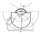
図7に、実施形態に係る位置特定部711の動作説明図を示す。図7において、図4と同様の部分には同一符号を付し、適宜説明を省略する。 FIG. 7 shows an operation explanatory view of the
ここで、スキャン角度をφとし、スキャン半径をrとし、OCT計測が可能な深さ範囲をdとし、断層像の深さ方向の長さをhとし、断層像の横方向の長さをwとする。スキャン角度φは、スキャン中心位置Csを中心とする測定光の偏向角度に相当する。スキャン半径rは、スキャン中心位置Csから測定光路長と参照光路長とが略等しい光路長ゼロ位置までの距離に相当する。深さ範囲dは、装置の光学設計等により一意に決定される装置固有の値(既知)である。 Here, the scan angle is φ, the scan radius is r, the depth range in which OCT measurement is possible is d, the length in the depth direction of the tomographic image is h, and the lateral length of the tomographic image is w. And. The scan angle φ corresponds to the deflection angle of the measurement light centered on the scan center position Cs. The scan radius r corresponds to the distance from the scan center position Cs to the position where the measured optical path length and the reference optical path length are substantially equal to the optical path length zero position. The depth range d is a device-specific value (known) that is uniquely determined by the optical design of the device or the like.
位置特定部711は、第1座標系における画素位置(x,z)から第2座標系における変換位置(X,Z)を特定する。第1座標系は、OCT画像(Bスキャン画像)における左上の座標位置を原点とし、Bスキャン方向をx方向とするx座標軸と、x座標軸に直交しAスキャン方向をz方向とするz座標軸とにより定義される。OCT画像における画素位置(x,z)は、第1座標系において定義される。第2座標系は、眼底Efにおける所定部位(例えば中心窩)を通過する測定光軸に対するスキャン角度が0度である測定光の進行方向をZ方向とするZ座標軸(例えば、第2軸)と、当該所定部位においてZ座標軸に直交するBスキャン方向をX方向とするX座標軸(例えば、第1軸)とにより定義される。第2座標系では、所定部位(例えば中心窩)を通過する測定光軸においてスキャン半径rの位置が最深部となるように所定のZ位置をZ座標軸の原点とする。また、下記のように所定の深さ方向の長さdとなるように、所定部位(例えば中心窩)を通過する測定光軸における所定のX位置をX座標軸の原点とする。変換位置(X,Z)は、第2座標系において定義される。変換位置(X,Z)は、画素位置(x,z)に対応し、スキャン中心位置Csを通る測定光の進行方向(Aスキャン方向)に沿った位置である。 The
位置特定部711は、OCT画像に対し、Aスキャン方向のスキャン半径r、スキャン角度φ、OCT計測が可能な深さ範囲d、及び画素位置(x,z)に基づいて、変換位置(X,Z)を特定する。位置特定部711は、変換位置のX成分(第1軸方向の成分)及びZ成分(第2軸方向の成分)の少なくとも1つを特定することが可能である。 The
Aスキャンライン数をN(Nは自然数)とするOCT画像(断層像)について、n(nは自然数)番目のAスキャンラインにおける画素位置(x,z)に対応する変換位置(X,Z)は、式(1)及び式(2)に示すように特定される。 For an OCT image (tomographic image) in which the number of A scan lines is N (N is a natural number), the conversion position (X, Z) corresponding to the pixel position (x, z) in the nth (n is a natural number) A scan line. Is specified as shown in equations (1) and (2).

ここで、OCT画像の深さ方向の長さh、横方向の長さw、及び画素位置のx成分は、式(3)〜式(5)のように表される。 Here, the length h in the depth direction, the length w in the horizontal direction, and the x component of the pixel position of the OCT image are expressed as equations (3) to (5).
式(1)、(2)において、画素位置のx座標は式(5)のように表される。従って、位置特定部711は、画素位置(x,z)から、スキャン半径r、スキャン角度φ、及び深さ範囲dに基づいて、変換位置(X,Z)を特定することが可能である。 In equations (1) and (2), the x-coordinate of the pixel position is expressed as in equation (5). Therefore, the
いくつかの実施形態では、位置特定部711は、スキャンデータに対して、上記と同様に、Aスキャン方向のスキャン半径r、スキャン角度φ、OCT計測が可能な深さ範囲d、及び、スキャン位置に基づいて、変換位置(X,Z)を特定することが可能である。 In some embodiments, the
いくつかの実施形態では、スキャン半径rは、干渉光学系40により得られた干渉光の検出結果を解析することにより特定される。これにより、被検眼Eの眼球光学特性をより正確に反映した変換位置(X,Z)を特定することが可能である。 In some embodiments, the scan radius r is identified by analyzing the detection results of the interference light obtained by the interference
いくつかの実施形態では、位置特定部711は、被検眼Eの角膜形状情報に基づいて測定光に対して光線追跡処理を施すことによりスキャン角度φを特定する。角膜形状情報には、角膜曲率半径(角膜前面の曲率半径、角膜後面の曲率半径)、角膜厚などがある。これにより、被検眼Eの眼球光学特性をより正確に反映した変換位置(X,Z)を特定することが可能である。 In some embodiments, the
(位置変換部)
位置変換部712は、OCT画像の画素位置(x,z)を位置特定部711により特定された変換位置(X,Z)に変換する。いくつかの実施形態では、OCT画像の全画素位置のそれぞれについて、位置特定部711が変換位置を特定し、位置変換部712が画素位置を変換位置に変換する。(Position conversion unit)
The
それにより、図8に示すように、Aスキャンにより取得されたAスキャン画像をAスキャン方向に配置することが可能になる。従って、図9に示す断層像IMG1のように、画角が広い場合でも、所定部位の形状が実際の形状と同様の断層像を取得することができる。 As a result, as shown in FIG. 8, the A-scan image acquired by the A-scan can be arranged in the A-scan direction. Therefore, as in the tomographic image IMG1 shown in FIG. 9, even when the angle of view is wide, it is possible to obtain a tomographic image in which the shape of the predetermined portion is the same as the actual shape.
例えば、図5に示す断層像IMG0及び図9に示す断層像IMG1の双方は、網膜剥離が生じた眼底Efの断層像である。断層像IMG1では、眼底Efにおける広範囲の神経網膜の剥離状態が実際の形態として描出されるため、断層像IMG0と比較して当該剥離状態を把握し易くなる。 For example, both the tomographic image IMG0 shown in FIG. 5 and the tomographic image IMG1 shown in FIG. 9 are tomographic images of the fundus Ef in which retinal detachment has occurred. In the tomographic image IMG1, since the detached state of the nerve retina in a wide range in the fundus Ef is depicted as an actual form, it becomes easier to grasp the detached state as compared with the tomographic image IMG0.
(補間部)
補間部713は、変換位置の間の画素を補間する。例えば、上記のようにスキャン中心位置Csからの距離に応じて、画素位置が変換位置に変換され互いに隣接するAスキャン画像の間隔が変化する。補間部713は、Aスキャン画像の深さ位置に応じて、互いに隣接するAスキャン画像の画素を用いてAスキャン画像の間の画素を補間する。補間部713による画素の補間処理として、ニアレストネイバー法、バイリニア補間法、バイキュービック補間法などの公知の方法を採用することが可能である。いくつかの実施形態では、補間部713は、スキャン中心位置Csからの距離に応じて、互いに隣接するAスキャン画像の間の画素を補間する。例えば、補間部713は、スキャン中心位置Csからの距離に応じて補間処理方法を変更して、互いに隣接するAスキャン画像の間の画素を補間する。(Interpolating part)
The
いくつかの実施形態では、スキャンデータにおけるスキャン位置に対して、上記と同様に、スキャンデータを補間する。 In some embodiments, the scan data is interpolated with respect to the scan position in the scan data, as described above.
(解析部)
図6に示す解析部72は、層領域特定部721と、法線方向特定部722と、層厚算出部723と、分布情報生成部724とを含む。層領域特定部721は、境界特定部721Aと、近似処理部721Bとを含む。(Analysis department)
The analysis unit 72 shown in FIG. 6 includes a layer
(層領域特定部)
層領域特定部721は、形状補正部71(位置変換部712)により画素位置が変換されたOCT画像(補間部713により画素が補間されたOCT画像)を解析して、眼底Ef(網膜)における所定の層領域を特定する。層領域として、網膜における層、ブルッフ膜、脈絡膜、強膜などがある。網膜における層には、網膜色素上皮層、視細胞層、外境界膜、外顆粒層、外網状層、内顆粒層、内網状層、神経節細胞層、神経線維層、内境界膜などがある。(Layer area identification part)
The layer
層領域特定部721は、形状補正部71により補正された眼底EfのOCT画像の画素値に基づいて、所定の層領域に相当する画像領域に含まれる複数の画素を特定する。いくつかの実施形態では、層領域特定部721は、OCT画像における隣接する画素の画素値の変化が所定の第1閾値以下である画素の領域を特定対象の層領域として特定する。 The layer
(境界特定部)
境界特定部721Aは、上記のようにOCT画像を解析することにより上記の層領域の境界(境界領域)を特定する。層領域の境界として、網膜における上記の層の境界のいずれか、ブルッフ膜の境界、脈絡膜の境界、強膜の境界、硝子体の境界などがある。(Boundary identification part)
The boundary specifying unit 721A identifies the boundary (boundary region) of the layer region by analyzing the OCT image as described above. The boundary of the layered region includes any of the above-mentioned layer boundaries in the retina, the Bruch's membrane boundary, the choroidal boundary, the scleral boundary, the vitreous boundary, and the like.
いくつかの実施形態では、境界特定部721Aは、OCT画像における隣接する画素の画素値の変化が所定の第2閾値以上である画素の領域を層領域の境界として特定する。いくつかの実施形態では、境界特定部721Aは、層領域特定部721により特定された2つの層領域の間の画像領域を層領域の境界として特定する。 In some embodiments, the boundary specifying unit 721A specifies a pixel region in which the change in the pixel value of adjacent pixels in the OCT image is equal to or greater than a predetermined second threshold value as the boundary of the layer region. In some embodiments, the boundary identifying section 721A identifies the image region between the two layer regions identified by the layer
OCT画像が2次元画像である場合、境界特定部721Aは、層領域特定部721により特定された層領域の境界線を特定する。この場合、境界特定部721Aにより特定される境界線は、1次元又は2次元の画像領域であってよい。 When the OCT image is a two-dimensional image, the boundary specifying unit 721A identifies the boundary line of the layer region specified by the layer
OCT画像が3次元画像である場合、境界特定部721Aは、層領域特定部721により特定された層領域の境界面を特定する。この場合、境界特定部721Aにより特定される境界面は、1次元、2次元又は3次元の画像領域であってよい。 When the OCT image is a three-dimensional image, the boundary specifying unit 721A identifies the boundary surface of the layer region specified by the layer
(近似処理部)
近似処理部721Bは、層領域特定部721により特定された層領域(又は境界特定部721Aにより特定された境界)に対して近似処理を施す。(Approximation processing unit)
The
例えば、OCT画像が2次元である場合、近似処理部721Bは、境界特定部721Aにより特定された境界(境界線)の近似曲線を求める。近似処理部721Bは、特定された境界領域又はその周辺の領域の画素に基づいて近似曲線を求める。この近似曲線は、任意の手法で求めることができる。例えば、近似処理部721Bは、スプライン曲線、線形近似曲線、対数近似曲線、多項式近似曲線、累乗近似曲線、指数近似曲線、移動平均近似曲線などの公知の曲線により上記の境界を近似する。 For example, when the OCT image is two-dimensional, the
例えば、OCT画像が3次元である場合、近似処理部721Bは、境界特定部721Aにより特定された境界(境界面)の近似面(又は近似曲線)を求める。近似処理部721Bは、特定された境界領域又はその周辺の領域の画素に基づいて近似曲面を求める。この近似曲面は、任意の手法で求めることができる。例えば、近似処理部721Bは、スプライン曲面、線形近似曲面、対数近似曲面、多項式近似曲面、累乗近似曲面、指数近似曲面、移動平均近似曲面などの公知の曲面により上記の境界を近似する。 For example, when the OCT image is three-dimensional, the
(法線方向特定部)
法線方向特定部722は、眼底Efにおける測定光の2以上の入射位置のそれぞれについて法線方向を特定する。具体的には、法線方向特定部722は、層領域特定部721により特定された層領域の2以上の位置のそれぞれについて法線方向を特定する。この実施形態では、近似処理部721Bにより得られた層領域(又はその境界)の近似曲線又は近似曲面が眼底Efの形状を表す情報であるものとし、法線方向特定部722は、層領域の境界の近似曲線又は近似曲面における2以上の位置のそれぞれについて法線方向を特定する。それにより、眼底Efの形状に対応した法線方向が得られる。(Normal direction identification part)
The normal
法線方向特定部722は、曲線又は曲面上の任意の位置に対する公知の処理により法線方向を特定することが可能である。 The normal
(層厚算出部)
層厚算出部723は、眼底Efにおける所定の層領域について、法線方向特定部722により特定された法線方向の距離を層厚として算出する。いくつかの実施形態では、層厚算出部723は、層領域特定部721により特定された層領域における法線方向の距離を算出する。いくつかの実施形態では、法線方向が特定された入射位置に対してz方向に上層又は下層の層領域における法線方向の距離を算出する。(Layer thickness calculation unit)
The layer
層厚算出部723は、算出対象の層領域の2以上の位置について法線方向の距離を算出することが可能である。また、層厚算出部723は、あらかじめ決められた層領域について所定の位置における法線方向の距離を算出することが可能である。 The layer
例えば、2点間の距離は、断層像中のピクセル数により特定され、特定されたピクセル数に装置固有のピクセルサイズを乗算することで計測される。このとき、断層像中の全ピクセルについて、同一のピクセルサイズが採用される。層厚算出部723は、特定された法線方向の法線上の2点間のピクセル数をカウントすることにより、上記の距離を算出する。 For example, the distance between two points is specified by the number of pixels in the tomographic image and is measured by multiplying the specified number of pixels by the device-specific pixel size. At this time, the same pixel size is adopted for all the pixels in the tomographic image. The layer
(分布情報生成部)
分布情報生成部724は、層厚算出部723により算出された層領域の距離(厚さ)の分布を表す分布情報を生成する。分布情報は、Aスキャン位置毎に層領域の距離を表す情報である。分布情報は、2以上のAスキャン位置の代表位置毎に層領域の距離を表す情報であってよい。分布情報生成部724は、層厚算出部723により算出された層領域の距離をAスキャン位置(測定光の入射位置)に対応付けることにより分布情報を生成することが可能である。分布情報生成部724は、2次元又は3次元の分布情報を生成することができる。(Distribution information generator)
The distribution
表示制御部51Aは、分布情報生成部724により生成された分布情報に対応した画像をUI部8の表示デバイスに表示させる。いくつかの実施形態では、表示制御部51Aは、層厚算出部723により算出された層領域の距離(厚さ)に応じた表示態様で分布情報に対応した画像をUI部8の表示デバイスに表示させる。分布情報に対応した画像としては、Aスキャン位置毎に、当該Aスキャン位置に対応付けられた層領域の距離に対応した色(又は輝度)の画素が配置された画像などがある。 The display control unit 51A causes the display device of the
いくつかの実施形態では、表示制御部51Aは、所定の基準値以上の層領域の距離のAスキャン位置の画素と、基準値未満の層領域の距離のAスキャン位置の画素とで表示態様が異なるように、分布情報に対応した画像を表示デバイスに表示させる。所定の基準値として、層領域の距離の統計値(平均値、中央値、最頻値、最小値、最大値など)などがある。 In some embodiments, the display control unit 51A has a display mode of pixels at the A scan position at a distance of a layer region equal to or greater than a predetermined reference value and pixels at an A scan position at a distance of a layer region less than the reference value. Differently, the image corresponding to the distribution information is displayed on the display device. As a predetermined reference value, there are statistical values (mean value, median value, mode value, minimum value, maximum value, etc.) of the distance of the layer region.
いくつかの実施形態では、表示制御部51Aは、所定の基準値を含む所定の範囲内の層領域の距離のAスキャン位置の画素と、当該範囲外の層領域の距離のAスキャン位置の画素とで表示態様が異なるように、分布情報に対応した画像を表示デバイスに表示させる。 In some embodiments, the display control unit 51A has pixels at the A scan position at a distance of a layer area within a predetermined range including a predetermined reference value and pixels at an A scan position at a distance of a layer area outside the range. An image corresponding to the distribution information is displayed on the display device so that the display mode is different between.
また、表示制御部51Aは、被検眼Eの画像、又は被検眼Eの別の計測結果に重畳するように、分布情報を表す画像を表示デバイスに表示させることが可能である。被検眼Eの画像として、画像形成部6により形成された被検眼Eの画像(OCT画像)、データ処理部7により画素位置が変換された被検眼Eの補正画像などがある。被検眼Eの別の計測結果として、被検眼Eの動的視野測定結果、又は被検眼Eの静的視野測定結果などがある。 Further, the display control unit 51A can display an image representing the distribution information on the display device so as to be superimposed on the image of the eye E to be inspected or another measurement result of the eye E to be inspected. As the image of the eye to be inspected E, there are an image of the eye to be inspected E (OCT image) formed by the
なお、解析部72は、層領域の距離だけではなく、眼内の任意の2点間の距離を求めることが可能である。すなわち、解析部72は、位置変換部712により変換されたOCT画像に基づいて被検眼Eにおける所定の部位間の眼内距離を求める。例えば、解析部72、変換されたOCT画像を解析することにより眼内の所定部位を特定し、特定された部位間の距離に基づいて上記の眼内距離を求める。 In addition, the analysis unit 72 can obtain not only the distance of the layer region but also the distance between any two points in the eye. That is, the analysis unit 72 obtains the intraocular distance between predetermined sites in the eye E to be inspected based on the OCT image converted by the
所定の部位間の眼内距離としては、指定された部位(組織、層領域)間の距離や、眼軸長や、瞳孔中心等に設定された測定光のスキャン中心位置から網膜までの距離などがある。眼内距離として眼軸長が求められる場合、解析部72は、角膜頂点に相当する部位から網膜に相当する部位までの距離に基づいて眼軸長を求める。 The intraocular distance between predetermined sites includes the distance between designated sites (tissue, layer region), the axial length of the eye, the distance from the scan center position of the measurement light set at the center of the pupil, etc. to the retina. There is. When the axial length is determined as the intraocular distance, the analysis unit 72 determines the axial length based on the distance from the portion corresponding to the apex of the cornea to the portion corresponding to the retina.
以上のように機能するデータ処理部7は、例えば、前述のプロセッサ、RAM、ROM、ハードディスクドライブ、回路基板等を含んで構成される。ハードディスクドライブ等の記憶装置には、上記機能をプロセッサに実行させるコンピュータプログラムがあらかじめ格納されている。 The data processing unit 7 that functions as described above includes, for example, the above-mentioned processor, RAM, ROM, hard disk drive, circuit board, and the like. A computer program that causes the processor to execute the above functions is stored in a storage device such as a hard disk drive in advance.
<ユーザインターフェイス部>
ユーザインターフェイス(UI)部8は、ユーザと眼科装置1との間で情報のやりとりを行うための機能を備える。ユーザインターフェイス部8は、表示デバイスと操作デバイス(入力デバイス)とを含む。表示デバイスは、例えば液晶ディスプレイ(LCD)を含む。操作デバイスは、各種のハードウェアキー及び/又はソフトウェアキーを含む。制御部5は、操作デバイスに対する操作内容を受け、この操作内容に対応した制御信号を各部に出力する。操作デバイスの少なくとも一部と表示デバイスの少なくとも一部とを一体的に構成することが可能である。タッチパネルディスプレイはその一例である。<User interface section>
The user interface (UI)
上記のように、表示制御部51Aは、UI部8の表示デバイスを制御することにより各種の画像を表示させる。特に、表示制御部51Aは、画像形成部6により形成された断層像、データ処理部7による処理後の断層像を表示デバイスに表示させることが可能である。表示制御部51Aは、画像形成部6により形成された断層像と、データ処理部7による処理後の断層像とを表示デバイスの同一画面に同時に表示させることが可能である。データ処理部による処理後の断層像として、位置変換部712により変換された断層像、補間部713により補間された断層像、解析部72による処理後の画像などがある。 As described above, the display control unit 51A displays various images by controlling the display device of the
形状補正部71は、実施形態に係る「補正部」の一例である。層領域特定部721は、実施形態に係る「領域特定部」の一例である。法線方向特定部722は、実施形態に係る「方向特定部」の一例である。層厚算出部723は、実施形態に係る「算出部」の一例である。UI部8の表示デバイスは、実施形態に係る「表示デバイス」の一例である。干渉光学系40、走査光学系30、及び画像形成部6(又はデータ処理部7)は、実施形態に係る「OCT部」の一例である。 The
[動作]
実施形態に係る眼科装置1の動作について説明する。[motion]
The operation of the
図10〜図12に、実施形態に係る眼科装置1の動作例を示す。図10〜図12は、実施形態に係る眼科装置1の動作例のフローチャートを表す。図11は、図10のステップS7の動作例のフローチャートを表す。図12は、図10のステップS8の動作例のフローチャートを表す。記憶部52には、図10〜図12に示す処理を実現するためのコンピュータプログラムが記憶されている。主制御部51は、このコンピュータプログラムに従って動作することにより、図10〜図12に示す処理を実行する。 10 to 12 show an operation example of the
(S1:アライメント)
主制御部51は、アライメントを実行する。(S1: Alignment)
The main control unit 51 executes alignment.
例えば、主制御部51は、図示しないアライメント系を制御して、被検眼Eにアライメント指標を投影させる。このとき、被検眼Eには、固視光学系50により所定の投射位置(例えば、測定光軸O上の投射位置)に固視光束が投射される。主制御部51は、観察光学系20により取得された受光像に基づいて特定された光学系2の移動量に基づいてxyz移動機構4Aを制御し、被検眼Eに対して光学系2を当該移動量だけ相対的に移動させる。主制御部51は、この処理を繰り返し実行させる。 For example, the main control unit 51 controls an alignment system (not shown) to project an alignment index on the eye E to be inspected. At this time, the fixation light beam is projected onto the eye E to be inspected by the fixation
いくつかの実施形態では、ステップS1におけるアライメント完了後に、上記のアライメント粗調整及びアライメント微調整が行われる。 In some embodiments, after the alignment in step S1 is completed, the above-mentioned coarse alignment adjustment and fine alignment adjustment are performed.
(S2:調整用断層像を取得)
主制御部51は、例えば、眼底Efにおける測定光軸O上の位置にOCT計測用の固視光束を投射させる。(S2: Obtain a tomographic image for adjustment)
The main control unit 51 projects, for example, a fixed-point luminous flux for OCT measurement at a position on the measurement optical axis O on the fundus Ef.
続いて、主制御部51は、走査光学系30及び干渉光学系40を制御してOCT仮計測を実行させ、深さ方向の計測範囲の基準位置を調整するための調整用断層像を取得させる。具体的には、主制御部51は、走査光学系30の光スキャナーを制御することにより、OCT光源から出射された光に基づいて生成された測定光を偏向し、偏向された測定光で被検眼Eの所定部位(例えば眼底Ef)をスキャンさせる。測定光のスキャンにより得られた干渉光の検出結果は、クロックに同期してサンプリングされた後、画像形成部6に送られる。画像形成部6は、得られた干渉信号から被検眼Eの断層像(OCT画像)を形成する。 Subsequently, the main control unit 51 controls the scanning
いくつかの実施形態では、主制御部51は、駆動部4Dを制御して、スイング機構4Bにより所定の移動角度範囲内で光学系2を旋回させつつ、OCT計測を実行させる。 In some embodiments, the main control unit 51 controls the
(S3:深さ方向の基準位置を調整)
続いて、主制御部51は、深さ方向(z方向)の計測範囲の基準位置を調整する。(S3: Adjust the reference position in the depth direction)
Subsequently, the main control unit 51 adjusts the reference position of the measurement range in the depth direction (z direction).
例えば、主制御部51は、ステップS2において得られた断層像における所定の部位(例えば、強膜)をデータ処理部7に特定させ、特定された所定の部位の位置に対して深さ方向に所定の距離だけ離れた位置を計測範囲の基準位置として設定する。主制御部51は、基準位置に対応して、図示しない光路長変更部を制御する。また、測定光と参照光の光路長が略一致するようにあらかじめ決められた所定の位置が計測範囲の基準位置として設定されてもよい。 For example, the main control unit 51 causes the data processing unit 7 to specify a predetermined part (for example, sclera) in the tomographic image obtained in step S2, and in the depth direction with respect to the position of the specified predetermined part. A position separated by a predetermined distance is set as a reference position of the measurement range. The main control unit 51 controls an optical path length changing unit (not shown) corresponding to the reference position. Further, a predetermined position determined in advance so that the optical path lengths of the measurement light and the reference light substantially match may be set as the reference position of the measurement range.
(S4:フォーカス調整、偏波調整)
次に、主制御部51は、フォーカス調整制御及び偏波調整制御を実行する。(S4: Focus adjustment, polarization adjustment)
Next, the main control unit 51 executes focus adjustment control and polarization adjustment control.
例えば、主制御部51は、走査光学系30とビームスプリッタM2との間に配置された合焦レンズを所定の距離だけ移動させた後、走査光学系30及び干渉光学系40を制御してOCT計測を実行させる。主制御部51は、上記のように、OCT計測により得られた干渉光の検出結果に基づいて測定光のフォーカス状態をデータ処理部7に判定させる。データ処理部7による判定結果に基づいて測定光のフォーカス状態が適正ではないと判断されたとき、主制御部51は、再び合焦レンズの移動制御を行い、フォーカス状態が適正であると判断されるまで繰り返す。 For example, the main control unit 51 moves the focusing lens arranged between the scanning
また、例えば、主制御部51は、図示しない偏波コントローラを制御してOCT抗原からの光及び測定光の少なくとも一方の偏波状態を所定の量だけ変更した後、走査光学系30及び干渉光学系40を制御してOCT計測を実行させ、取得された干渉光の検出結果に基づくOCT画像を画像形成部6に形成させる。主制御部51は、上記のように、OCT計測により得られたOCT画像の画質をデータ処理部7に判定させる。データ処理部7による判定結果に基づいて測定光の偏波状態が適正ではないと判断されたとき、主制御部51は、再び偏波コントローラの制御を行い、偏波状態が適正であると判断されるまで繰り返す。 Further, for example, the main control unit 51 controls a polarization controller (not shown) to change the polarization state of at least one of the light from the OCT antigen and the measurement light by a predetermined amount, and then the scanning
(S5:干渉信号を取得)
続いて、主制御部51は、駆動部4Dを制御して、スイング機構4Bにより所定の移動角度範囲内で光学系2の旋回を開始させる。更に、主制御部51は、光学系2の旋回中に、走査光学系30及び干渉光学系40を制御してOCT計測を実行させる。当該OCT計測により取得された干渉光の検出結果は、DAQにおいてサンプリングされ、干渉信号として記憶部52等に保存される。(S5: Acquire interference signal)
Subsequently, the main control unit 51 controls the
(S6:断層像を形成)
次に、主制御部51は、ステップS5において取得された干渉信号に基づいて被検眼EのAスキャン画像データのデータセット群を画像形成部6に形成させる。画像形成部6は、形成されたAスキャン画像をBスキャン方向に配列することにより、図5に示すような断層像を形成する。(S6: Form a tomographic image)
Next, the main control unit 51 causes the
(S7:断層像を補正)
主制御部51は、例えば、記憶部52に記憶された眼球パラメータ52Aを用いて、ステップS6において形成された断層像を上記のように補正する。ステップS7の詳細について後述する。それにより、図9に示すように、Aスキャン画像がAスキャン方向に配列された断層像が取得される。(S7: Correct the tomographic image)
The main control unit 51 corrects the tomographic image formed in step S6 as described above by using, for example, the
(S8:解析)
続いて、主制御部51は、ステップS7において補正された断層像を解析部72により解析させる。ステップS8の詳細については後述する。(S8: Analysis)
Subsequently, the main control unit 51 causes the analysis unit 72 to analyze the tomographic image corrected in step S7. The details of step S8 will be described later.
(S9:表示)
主制御部51(表示制御部51A)は、ステップS8における解析処理により得られた結果を表示デバイスに表示させる(図13又は図14を参照)。(S9: Display)
The main control unit 51 (display control unit 51A) causes the display device to display the result obtained by the analysis process in step S8 (see FIG. 13 or FIG. 14).
いくつかの実施形態では、主制御部51は、図13に示すように、被検眼Eの眼底Efの3次元の断層像における画素にAスキャン位置を対応付け、Aスキャン位置毎に、層領域の厚さに対応して表示態様が変更された画素を重畳させて表示デバイスに表示させる。これにより、眼底周辺部や眼底の形状が変形している場合でも、層領域の正しい厚さを正確に把握することができる。特に、眼底Efにおける菲薄化した層領域や浮腫を正確に把握することができる。 In some embodiments, as shown in FIG. 13, the main control unit 51 associates the A scan position with the pixel in the three-dimensional tomographic image of the fundus Ef of the eye to be inspected E, and for each A scan position, the layer area. Pixels whose display mode has been changed according to the thickness of the above are superimposed and displayed on the display device. As a result, even when the shape of the fundus peripheral portion or the fundus is deformed, the correct thickness of the layer region can be accurately grasped. In particular, it is possible to accurately grasp the thinned layer region and edema in the fundus Ef.
いくつかの実施形態では、主制御部51は、図14に示すように、固視点を中心とした静的視野測定結果の測定点にAスキャン位置を対応付け、Aスキャン位置毎に、層領域の厚さに対応して表示態様が変更された画素を重畳させて表示デバイスに表示させる。これにより、眼底周辺部や眼底の形状が変形している場合でも、視野測定結果に関連付けて層領域の正しい厚さを正確に把握することができる。 In some embodiments, as shown in FIG. 14, the main control unit 51 associates the A scan position with the measurement point of the static visual field measurement result centered on the fixed viewpoint, and each A scan position has a layer area. Pixels whose display mode has been changed according to the thickness of the above are superimposed and displayed on the display device. As a result, even when the shape of the fundus peripheral portion or the fundus is deformed, the correct thickness of the layer region can be accurately grasped in relation to the visual field measurement result.
以上で、眼科装置1の動作は終了である(エンド)。 This is the end of the operation of the ophthalmic apparatus 1 (end).
図10のステップS7では、図11に示すように次のような処理が実行される。 In step S7 of FIG. 10, the following processing is executed as shown in FIG.
(S11:変換位置を算出)
ステップS7において、主制御部51は、ステップS6において形成された断層像の画素位置に対応した変換位置を位置特定部711に特定させる。位置特定部711は、上記のように、断層像の画素位置に対応する変換位置を特定する。(S11: Calculate the conversion position)
In step S7, the main control unit 51 causes the
(S12:画素位置を変換)
続いて、主制御部51は、位置変換部712を制御することにより、断層像の画素位置をステップS11において算出された変換位置に変換させる。(S12: Convert pixel position)
Subsequently, the main control unit 51 controls the
(S13:次?)
主制御部51は、次に変換すべき画素位置があるか否かを判定する。(S13: Next?)
The main control unit 51 determines whether or not there is a pixel position to be converted next.
次に変換すべき画素位置があると判定されたとき(S13:Y)、眼科装置1の動作はステップS11に移行する。次に変換すべき画素位置がないと判定されたとき(S13:N)、眼科装置1の動作はステップS14に移行する。 Next, when it is determined that there is a pixel position to be converted (S13: Y), the operation of the
ステップS11〜S13により、断層像の画素位置毎に、変換位置の特定と、特定された変換位置への変換が行われる。 In steps S11 to S13, the conversion position is specified and the conversion to the specified conversion position is performed for each pixel position of the tomographic image.
(S14:補間)
ステップS13において、次に変換すべき画素位置がないと判定されたとき(S13:N)、主制御部51は、ステップS12において変換位置に変換された互いに隣接するAスキャン画像の間の画素を補間部713に補間させる。(S14: Interpolation)
When it is determined in step S13 that there is no pixel position to be converted next (S13: N), the main control unit 51 shifts the pixels between the adjacent A-scan images converted to the conversion position in step S12. The
以上で、図10のステップS7の処理は終了である(エンド)。 This completes the process of step S7 in FIG. 10 (end).
図10のステップS8では、図12に示すように次のような処理が実行される。 In step S8 of FIG. 10, the following processing is executed as shown in FIG.
(S21:層領域を特定)
ステップS8において、主制御部51は、ステップS7において補正された断層像における層領域を層領域特定部721に特定させる。層領域特定部721は、上記のように、眼底Efにおける所定の層領域を特定する。(S21: Specify the layer area)
In step S8, the main control unit 51 causes the layer
(S22:近似処理)
次に、主制御部51は、ステップS21において特定された層領域(境界)に対して近似処理部721Bにより近似処理を実行させる。近似処理部721Bは、上記のように、層領域特定部721により特定された層領域(又は境界特定部721Aにより特定された境界)に対して近似処理を施す。(S22: Approximation processing)
Next, the main control unit 51 causes the
(S23:法線方向を特定)
次に、主制御部51は、ステップS22における近似処理により得られた層領域(境界)の近似曲線(近似曲面)に基づいて、2以上の位置における法線方向を法線方向特定部722に特定させる。法線方向特定部722は、上記のように、層領域(又はその境界)の近似曲線又は近似曲面における2以上の位置のそれぞれについて法線方向を特定する。(S23: Specify the normal direction)
Next, the main control unit 51 sets the normal direction at two or more positions to the normal
(S24:層厚を算出)
続いて、主制御部51は、ステップS21において特定された層領域についてステップS23において特定された法線方向の距離を層厚算出部723に算出させる。層厚算出部723は、上記のように層領域の法線方向の距離を算出する。(S24: Calculate the layer thickness)
Subsequently, the main control unit 51 causes the layer
(S25:分布情報を生成)
更に、主制御部51は、ステップS24において算出された層領域の距離(厚さ)をAスキャン位置に対応付けることにより分布情報を生成する。生成された分布情報は、図13又は図14に示すように表示デバイスに表示される。(S25: Generate distribution information)
Further, the main control unit 51 generates distribution information by associating the distance (thickness) of the layer region calculated in step S24 with the A scan position. The generated distribution information is displayed on the display device as shown in FIG. 13 or FIG.
以上で、図10のステップS8の処理は終了である(エンド)。 This completes the process of step S8 in FIG. 10 (end).
<変形例>
上記の実施形態では、2次元のOCT画像(又は2次元のスキャンデータ)を座標変換により補正する場合について説明したが、実施形態に係る構成はこれに限定されるものではない。実施形態に係る眼科装置は、上記の実施形態と同様に、3次元のOCT画像(又は3次元のスキャンデータ)を座標変換することにより補正することが可能である。以下、実施形態の変形例に係る眼科装置について、実施形態との相違点を中心に説明する。<Modification example>
In the above embodiment, the case where the two-dimensional OCT image (or the two-dimensional scan data) is corrected by the coordinate conversion has been described, but the configuration according to the embodiment is not limited to this. The ophthalmic apparatus according to the embodiment can be corrected by coordinate-transforming a three-dimensional OCT image (or three-dimensional scan data) as in the above embodiment. Hereinafter, the ophthalmic apparatus according to the modified example of the embodiment will be described focusing on the differences from the embodiment.
実施形態の変形例に係る眼科装置の構成は実施形態に係る眼科装置1の構成と同様であるため、説明を省略する。 Since the configuration of the ophthalmic apparatus according to the modified example of the embodiment is the same as the configuration of the
本変形例に係るデータ処理部は、3次元空間における変換位置の特定処理等を行う。 The data processing unit according to this modification performs processing for specifying the conversion position in the three-dimensional space.
本変形例に係る位置特定部711は、取得されたOCT画像における画素位置(又はスキャンデータにおけるスキャン位置)に対応し、スキャン中心位置Csを通る測定光の進行方向に沿った変換位置を特定する。いくつかの実施形態では、位置特定部711は、眼球パラメータ52Aを用いて変換位置を特定する。 The
図15に、本変形例に係る位置特定部711の動作説明図を示す。図15において、図7と同様の部分には同一符号を付し、適宜説明を省略する。 FIG. 15 shows an operation explanatory view of the
図15では、図7におけるX平面及びZ平面の他に、Y平面が定義される。図7に示すパラメータに加えて、Cスキャン方向の中心角をθとし、Cスキャン方向の長さをlcとする。 In FIG. 15, in addition to the X plane and the Z plane in FIG. 7, the Y plane is defined. In addition to the parameters shown in FIG. 7, the central angle in the C scan direction is θ, and the length in the C scan direction is lc.
位置特定部711は、第3座標系における画素位置(x,y,z)から第4座標系における変換位置(X,Y,Z)を特定する。第3座標系は、3次元のOCT画像における左上隅の座標位置を原点とし、Bスキャン方向をx方向とするx座標軸と、x座標軸と直交しCスキャン方向をy方向とするy座標軸と、x座標軸及びy座標軸の双方に直交しAスキャン方向をz方向とするz座標軸とにより定義される。OCT画像における画素位置(x,y,z)は、第3座標系において定義される。第4座標系は、眼底Efにおける所定部位(例えば中心窩)を通過する測定光軸に対するスキャン角度が0度である測定光の進行方向をZ方向とするZ座標軸と、当該所定部位においてZ座標軸に直交するBスキャン方向をX方向とするX座標軸と、当該所定部位においてZ座標軸に直交するCスキャン方向をY方向とするY座標軸とにより定義される。第4座標系では、所定部位(例えば中心窩)を通過する測定光軸においてスキャン半径rの位置が最深部となるように所定のZ位置をZ座標軸の原点とする。また、下記のように所定の深さ方向の長さdとなるように、所定部位(例えば中心窩)を通過する測定光軸における所定のX位置及びY位置をX座標軸及びY座標軸の原点とする。変換位置(X,Y,Z)は、第4座標系において定義される。変換位置(X,Y,Z)は、画素位置(x,y,z)に対応し、スキャン中心位置Csを通る測定光の進行方向(Aスキャン方向)に沿った位置である。 The
位置特定部711は、変換位置のX成分、Y成分及びZ成分の少なくとも1つを特定することが可能である。 The
Aスキャンライン数をN(Nは自然数)とし、Bスキャンライン数をM(Mは自然数)とするOCT画像(断層像)について、m(mは自然数)番目のBスキャンのn(nは自然数)番目のAスキャンラインにおける画素位置(x,y,z)に対応する変換位置(X,Y,Z)は、式(6)〜式(8)に示すように特定される。 For an OCT image (tomographic image) in which the number of A scan lines is N (N is a natural number) and the number of B scan lines is M (M is a natural number), the m (m is a natural number) th B scan n (n is a natural number). The conversion positions (X, Y, Z) corresponding to the pixel positions (x, y, z) in the) th A scan line are specified as shown in equations (6) to (8).
ここで、3次元のOCT画像の深さ方向の長さhとBスキャン方向の長さwとCスキャン方向の長さlcとから、画素位置のx成分及びy成分は、式(9)〜式(13)のように表される。 Here, from the length h in the depth direction, the length w in the B scan direction, and the length lc in the C scan direction of the three-dimensional OCT image, the x component and the y component of the pixel position are obtained from the equations (9) to It is expressed as in equation (13).
式(6)〜(8)において、画素位置のx座標及びy座標は式(12)及び式(13)のように表される。従って、位置特定部711は、画素位置(x,y,z)から、スキャン半径r、スキャン角度φ、及び深さ範囲dに基づいて、変換位置(X,Y,Z)を特定することが可能である。 In the equations (6) to (8), the x-coordinate and the y-coordinate of the pixel position are expressed as the equations (12) and (13). Therefore, the
いくつかの実施形態では、位置特定部711は、スキャンデータに対して、上記と同様に、変換位置(X,Y,Z)を特定することが可能である。 In some embodiments, the
本変形例に係る位置変換部712は、OCT画像の画素位置(x,y,z)を位置特定部711により特定された変換位置(X,Y,Z)に変換する。いくつかの実施形態では、OCT画像の全画素位置のそれぞれについて、位置特定部711が変換位置を特定し、位置変換部712が画素位置を変換位置に変換する。 The
上記の実施形態では、光学系2等を含む眼科装置により断層像が補正される場合について説明したが、実施形態に係る構成はこれに限定されるものではない。例えば、図6に示すデータ処理部7の機能を実現する眼科情報処理装置が、取得されたOCT画像(又はスキャンデータ)に対して上記のように断層像を補正し、補正された断層像に対して偏心量及び偏心方向に基づいて回転処理を実行するようにしてもよい。この場合、OCT画像(又はスキャンデータ)は外部のOCT装置(眼科装置)により取得される。 In the above embodiment, the case where the tomographic image is corrected by the ophthalmic apparatus including the optical system 2 and the like has been described, but the configuration according to the embodiment is not limited to this. For example, an ophthalmic information processing device that realizes the function of the data processing unit 7 shown in FIG. 6 corrects the tomographic image of the acquired OCT image (or scan data) as described above, and obtains the corrected tomographic image. On the other hand, the rotation process may be executed based on the eccentricity amount and the eccentricity direction. In this case, the OCT image (or scan data) is acquired by an external OCT device (ophthalmic device).
いくつかの実施形態では、上記の眼科装置の制御方法をコンピュータに実行させるためのプログラムが提供される。このようなプログラムを、コンピュータによって読み取り可能な任意の記録媒体に記憶させることができる。この記録媒体としては、たとえば、半導体メモリ、光ディスク、光磁気ディスク(CD−ROM/DVD−RAM/DVD−ROM/MO等)、磁気記憶媒体(ハードディスク/フロッピー(登録商標)ディスク/ZIP等)などを用いることが可能である。また、インターネットやLAN等のネットワークを通じてこのプログラムを送受信することも可能である。 In some embodiments, a program is provided for causing a computer to perform the control method of the ophthalmic apparatus described above. Such a program can be stored in any computer-readable recording medium. Examples of the recording medium include semiconductor memory, optical disk, magneto-optical disk (CD-ROM / DVD-RAM / DVD-ROM / MO, etc.), magnetic storage medium (hard disk / floppy (registered trademark) disk / ZIP, etc.) and the like. Can be used. It is also possible to send and receive this program through a network such as the Internet or LAN.
[効果]
実施形態に係る眼科情報処理装置、眼科装置、眼科情報処理方法、及びプログラムについて説明する。[effect]
The ophthalmic information processing device, the ophthalmic device, the ophthalmic information processing method, and the program according to the embodiment will be described.
いくつかの実施形態に係る眼科情報処理装置(例えば、データ処理部7を含む装置)は、スキャン中心位置(Cs)を中心に偏向された測定光で被検眼(E)の眼内をOCTスキャンすることにより得られた複数のAスキャン画像を配列することにより形成された被検眼の画像(OCT画像)を解析する。眼科情報処理装置は、補正部(形状補正部71)と、領域特定部(層領域特定部721)と、方向特定部(法線方向特定部722)とを含む。補正部は、画像の画素位置を、スキャン中心位置を通る測定光の進行方向に沿った変換位置に変換する。領域特定部は、補正部により画素位置が変換された画像を解析することにより所定の層領域を特定する。方向特定部は、領域特定部により特定された層領域の法線方向を特定する。 The ophthalmologic information processing apparatus according to some embodiments (for example, an apparatus including the data processing unit 7) scans the inside of the eye of the eye to be inspected (E) by OCT scan with the measurement light deflected around the scan center position (Cs). The image of the eye to be inspected (OCT image) formed by arranging a plurality of A-scan images obtained by the above is analyzed. The ophthalmic information processing apparatus includes a correction unit (shape correction unit 71), an area identification unit (layer area identification unit 721), and a direction identification unit (normal direction identification unit 722). The correction unit converts the pixel position of the image into a conversion position along the traveling direction of the measurement light passing through the scan center position. The region specifying unit identifies a predetermined layer region by analyzing an image whose pixel positions have been converted by the correction unit. The direction specifying unit specifies the normal direction of the layer region specified by the region specifying unit.
このような構成によれば、被検眼の画像の画素位置をスキャン中心位置を通る測定光の進行方向に沿った変換位置に変換することにより画像を補正し、補正された画像における所定の層領域の法線方向を特定するようにしたので、眼底周辺部や眼底の形状が変形している場合であっても、被検眼の眼底等の形態を正しく把握することが可能になる。 According to such a configuration, the image is corrected by converting the pixel position of the image to be inspected into a conversion position along the traveling direction of the measurement light passing through the scan center position, and a predetermined layer region in the corrected image is obtained. Since the normal direction of the above is specified, it is possible to correctly grasp the shape of the fundus of the eye to be inspected even when the shape of the peripheral portion of the fundus or the fundus is deformed.
いくつかの実施形態では、領域特定部は、層領域の境界線を特定する境界特定部(721A)と、境界特定部により特定された境界線の近似曲線を求める近似処理部(721B)と、を含み、方向特定部は、近似処理部により求められた近似曲線上の位置の法線方向を特定する。 In some embodiments, the region identification unit includes a boundary identification unit (721A) that specifies the boundary line of the layer region, and an approximation processing unit (721B) that obtains an approximation curve of the boundary line specified by the boundary identification unit. The direction specifying unit specifies the normal direction of the position on the approximate curve obtained by the approximate processing unit.
このような構成によれば、被検眼の2次元の画像を用いて、眼底周辺部や形状が変形している眼底等の形態を正しく把握することが可能になる。 According to such a configuration, it is possible to correctly grasp the morphology of the peripheral portion of the fundus and the fundus whose shape is deformed by using the two-dimensional image of the eye to be inspected.
いくつかの実施形態では、領域特定部は、層領域の境界面を特定する境界特定部(721A)と、境界特定部により特定された境界面の近似曲面を求める近似処理部(721B)と、を含み、方向特定部は、近似処理部により求められた近似曲面上の位置の法線方向を特定する。 In some embodiments, the region identification unit includes a boundary identification unit (721A) that specifies the boundary surface of the layer region, and an approximation processing unit (721B) that obtains an approximate curved surface of the boundary surface specified by the boundary identification unit. The direction specifying unit specifies the normal direction of the position on the approximate curved surface obtained by the approximation processing unit.
このような構成によれば、被検眼の3次元の画像を用いて、眼底周辺部や形状が変形している眼底等の形態を正しく把握することが可能になる。 According to such a configuration, it is possible to correctly grasp the morphology of the peripheral portion of the fundus and the fundus whose shape is deformed by using the three-dimensional image of the eye to be inspected.
いくつかの実施形態は、領域特定部により特定された層領域における法線方向の距離を求める算出部(層厚算出部723)を含む。 Some embodiments include a calculation unit (layer thickness calculation unit 723) for obtaining the distance in the normal direction in the layer region specified by the region identification unit.
このような構成によれば、眼底周辺部における層領域の厚さや、眼底の形状が変形している場合の層領域の厚さを、眼底中心部と同様に、正しく取得することが可能になる。 According to such a configuration, the thickness of the layer region in the peripheral portion of the fundus and the thickness of the layer region when the shape of the fundus is deformed can be correctly obtained in the same manner as in the central portion of the fundus. ..
いくつかの実施形態は、算出部により算出された距離の分布を表す分布情報を生成する分布情報生成部(724)を含む。 Some embodiments include a distribution information generation unit (724) that generates distribution information representing the distribution of distances calculated by the calculation unit.
このような構成によれば、眼底周辺部における層領域の厚さの分布や、眼底の形状が変形している場合の層領域の厚さの分布を、眼底中心部と同様に、正しく取得することが可能になる。 According to such a configuration, the distribution of the thickness of the layered region around the fundus and the distribution of the thickness of the layered region when the shape of the fundus is deformed can be correctly obtained as in the central part of the fundus. Will be possible.
いくつかの実施形態は、上記の距離に応じた表示態様で分布情報に対応した画像を表示手段(UI部8の表示デバイス)に表示させる表示制御部(51A)を含む。 Some embodiments include a display control unit (51A) that causes a display means (display device of the UI unit 8) to display an image corresponding to the distribution information in the display mode according to the above distance.
このような構成によれば、眼底周辺部における層領域の厚さの分布や、眼底の形状が変形している場合の層領域の厚さの分布を、眼底中心部と同様に、正しく把握することが可能になる。 According to such a configuration, the distribution of the thickness of the layer region around the fundus and the distribution of the thickness of the layer region when the shape of the fundus is deformed can be correctly grasped as in the central part of the fundus. Will be possible.
いくつかの実施形態では、表示制御部は、補正部により画素位置が変換された画像に分布情報に対応した画像を重畳表示させる。 In some embodiments, the display control unit superimposes and displays an image corresponding to the distribution information on the image whose pixel position has been converted by the correction unit.
このような構成によれば、眼底等の形状が補正された画像に分布情報に対応した画像に関連付けて、眼底周辺部における層領域の厚さの分布や、眼底の形状が変形している場合の層領域の厚さの分布を、眼底中心部と同様に、正しく把握することが可能になる。 According to such a configuration, when the thickness distribution of the layer region around the fundus and the shape of the fundus are deformed in association with the image in which the shape of the fundus is corrected and the image corresponding to the distribution information. It is possible to correctly grasp the distribution of the thickness of the layered region of the fundus as well as the central part of the fundus.
いくつかの実施形態では、表示制御部は、被検眼の動的視野測定又は静的視野測定の結果に分布情報に対応した画像を重畳表示させる。 In some embodiments, the display control unit superimposes and displays an image corresponding to the distribution information on the result of the dynamic visual field measurement or the static visual field measurement of the eye to be inspected.
このような構成によれば、被検眼の視野測定結果に関連付けて、眼底周辺部における層領域の厚さの分布や、眼底の形状が変形している場合の層領域の厚さの分布を、眼底中心部と同様に、正しく把握することが可能になる。 According to such a configuration, the distribution of the thickness of the layer region around the fundus and the distribution of the thickness of the layer region when the shape of the fundus is deformed are determined in relation to the visual field measurement result of the eye to be inspected. As with the central part of the fundus, it becomes possible to grasp correctly.
いくつかの実施形態では、表示制御部は、補正部により画素位置が変換された画像を法線方向に表示させる。 In some embodiments, the display control unit displays the image whose pixel position has been converted by the correction unit in the normal direction.
このような構成によれば、被検眼の実際の形状に合わせて眼底等の形態が描出された画像を表示させることができる。 According to such a configuration, it is possible to display an image in which a morphology such as a fundus is depicted according to the actual shape of the eye to be inspected.
いくつかの実施形態は、補正部により画素位置が変換された画像を法線方向に表示させる表示制御部(51A)を含む。 Some embodiments include a display control unit (51A) that displays an image whose pixel position has been converted by the correction unit in the normal direction.
このような構成によれば、被検眼の実際の形状に合わせて眼底等の形態が描出された画像を表示させることができる。 According to such a configuration, it is possible to display an image in which a morphology such as a fundus is depicted according to the actual shape of the eye to be inspected.
いくつかの実施形態に係る眼科装置(1)は、光コヒーレンストモグラフィを用いて被検眼の断層像を取得するOCT部(干渉光学系40、走査光学系30、及び画像形成部6(又はデータ処理部7))と、上記のいずれかに記載の眼科情報処理装置と、を含む。 The ophthalmic apparatus (1) according to some embodiments is an OCT unit (interference
このような構成によれば、眼底周辺部や眼底の形状が変形している場合であっても、被検眼の眼底等の形態を正しく把握することが可能な眼科装置を提供することができる。 According to such a configuration, it is possible to provide an ophthalmologic apparatus capable of correctly grasping the shape of the fundus of the eye to be inspected even when the shape of the peripheral portion of the fundus or the fundus is deformed.
いくつかの実施形態に係る眼科情報処理方法は、スキャン中心位置(Cs)を中心に偏向された測定光で被検眼(E)の眼内をOCTスキャンすることにより得られた複数のAスキャン画像を配列することにより形成された被検眼の画像を解析する。眼科情報処理方法は、画像の画素位置を、スキャン中心位置を通る測定光の進行方向に沿った変換位置に変換する補正ステップと、補正ステップにおいて画素位置が変換された画像を解析することにより所定の層領域を特定する領域特定ステップと、領域特定ステップにおいて特定された層領域の法線方向を特定する方向特定ステップと、を含む。 The ophthalmologic information processing method according to some embodiments is a plurality of A scan images obtained by OCT scanning the inside of the eye of the eye to be inspected (E) with measurement light deflected around the scan center position (Cs). The image of the eye to be inspected formed by arranging the above is analyzed. The ophthalmic information processing method is determined by analyzing a correction step of converting the pixel position of the image into a conversion position along the traveling direction of the measurement light passing through the scan center position and an image in which the pixel position is converted in the correction step. Includes an area specifying step for specifying the layer area of the above, and a direction specifying step for specifying the normal direction of the layer area specified in the area specifying step.
このような方法によれば、被検眼の画像の画素位置をスキャン中心位置を通る測定光の進行方向に沿った変換位置に変換することにより画像を補正し、補正された画像における所定の層領域の法線方向を特定するようにしたので、眼底周辺部や眼底の形状が変形している場合であっても、被検眼の眼底等の形態を正しく把握することが可能になる。 According to such a method, the image is corrected by converting the pixel position of the image of the eye to be examined to a conversion position along the traveling direction of the measurement light passing through the scan center position, and a predetermined layer region in the corrected image. Since the normal direction of the above is specified, it is possible to correctly grasp the shape of the fundus of the eye to be inspected even when the shape of the peripheral portion of the fundus or the fundus is deformed.
いくつかの実施形態は、領域特定ステップにおいて特定された層領域における法線方向の距離を求める算出ステップを含む。 Some embodiments include a calculation step of determining the distance in the normal direction in the layer region identified in the region identification step.
このような方法によれば、眼底周辺部における層領域の厚さや、眼底の形状が変形している場合の層領域の厚さを、眼底中心部と同様に、正しく取得することが可能になる。 According to such a method, the thickness of the layer region in the peripheral portion of the fundus and the thickness of the layer region when the shape of the fundus is deformed can be correctly obtained in the same manner as in the central portion of the fundus. ..
いくつかの実施形態は、上記の距離に応じた表示態様で、距離の分布を表す分布情報に対応した画像を表示手段(UI部8の表示デバイス)に表示させる表示制御ステップを含む。 Some embodiments include a display control step of displaying an image corresponding to the distribution information representing the distribution of the distance on the display means (display device of the UI unit 8) in the display mode according to the distance.
このような方法によれば、眼底周辺部における層領域の厚さの分布や、眼底の形状が変形している場合の層領域の厚さの分布を、眼底中心部と同様に、正しく把握することが可能になる。 According to such a method, the distribution of the thickness of the layer region around the fundus and the distribution of the thickness of the layer region when the shape of the fundus is deformed can be correctly grasped as in the central part of the fundus. Will be possible.
いくつかの実施形態では、表示制御ステップは、補正ステップにおいて画素位置が変換された画像に分布情報に対応した画像を重畳表示させる。 In some embodiments, the display control step superimposes and displays an image corresponding to the distribution information on the image whose pixel position is converted in the correction step.
このような方法によれば、眼底等の形状が補正された画像に分布情報に対応した画像に関連付けて、眼底周辺部における層領域の厚さの分布や、眼底の形状が変形している場合の層領域の厚さの分布を、眼底中心部と同様に、正しく把握することが可能になる。 According to such a method, when the thickness distribution of the layer region around the fundus and the shape of the fundus are deformed in association with the image in which the shape of the fundus is corrected and the image corresponding to the distribution information. It is possible to correctly grasp the distribution of the thickness of the layered region of the fundus as well as the central part of the fundus.
いくつかの実施形態では、表示制御ステップは、被検眼の動的視野測定又は静的視野測定の結果に分布情報に対応した画像を重畳表示させる。 In some embodiments, the display control step superimposes an image corresponding to the distribution information on the result of the dynamic visual field measurement or the static visual field measurement of the eye to be inspected.
このような方法によれば、被検眼の視野測定結果に関連付けて、眼底周辺部における層領域の厚さの分布や、眼底の形状が変形している場合の層領域の厚さの分布を、眼底中心部と同様に、正しく把握することが可能になる。 According to such a method, the distribution of the thickness of the layer region around the fundus and the distribution of the thickness of the layer region when the shape of the fundus is deformed are determined in relation to the visual field measurement result of the eye to be inspected. As with the central part of the fundus, it becomes possible to grasp correctly.
いくつかの実施形態は、補正ステップにおいて画素位置が変換された画像を法線方向に表示させる表示制御ステップを含む。 Some embodiments include a display control step of displaying an image whose pixel position has been changed in the correction step in the normal direction.
このような方法によれば、被検眼の実際の形状に合わせて眼底等の形態が描出された画像を表示させることができる。 According to such a method, it is possible to display an image in which a morphology such as a fundus is depicted according to the actual shape of the eye to be inspected.
いくつかの実施形態に係るプログラムは、コンピュータに、上記のいずれかに記載の眼科情報処理方法の各ステップを実行させる。 The program according to some embodiments causes a computer to perform each step of the ophthalmic information processing method described in any of the above.
このようなプログラムによれば、被検眼の画像の画素位置をスキャン中心位置を通る測定光の進行方向に沿った変換位置に変換することにより画像を補正し、補正された画像における所定の層領域の法線方向を特定するようにしたので、眼底周辺部や眼底の形状が変形している場合であっても、被検眼の眼底等の形態を正しく把握することが可能になる。 According to such a program, the image is corrected by converting the pixel position of the image of the eye to be examined to a conversion position along the traveling direction of the measurement light passing through the scan center position, and a predetermined layer region in the corrected image. Since the normal direction of the above is specified, it is possible to correctly grasp the shape of the fundus of the eye to be inspected even when the shape of the peripheral portion of the fundus or the fundus is deformed.
<その他>
以上に示された実施形態又はその変形例は、この発明を実施するための一例に過ぎない。この発明を実施しようとする者は、この発明の要旨の範囲内において任意の変形、省略、追加等を施すことが可能である。<Others>
The embodiment shown above or a modification thereof is only an example for carrying out the present invention. A person who intends to carry out the present invention can make arbitrary modifications, omissions, additions, etc. within the scope of the gist of the present invention.
1 眼科装置
2 光学系
5 制御部
51 主制御部
51A 表示制御部
52 記憶部
52A 眼球パラメータ
6 画像形成部
7 データ処理部
71 形状補正部
711 位置特定部
712 位置変換部
713 補間部
72 解析部
721 領域特定部
721A 境界特定部
721B 近似処理部
722 法線方向特定部
723 層厚算出部
724 分布情報生成部
8 UI部
30 走査光学系
40 干渉光学系
50 固視光学系
E 被検眼
Ef 眼底
M1〜M3 ビームスプリッタ
O 測定光軸1 Ophthalmic apparatus 2 Optical system 5 Control unit 51 Main control unit 51A Display control unit 52
Claims (18)
Translated fromJapanese前記画像の画素位置を、前記スキャン中心位置を通る前記測定光の進行方向に沿った変換位置に変換する補正部と、
前記補正部により画素位置が変換された画像を解析することにより所定の層領域を特定する領域特定部と、
前記領域特定部により特定された前記層領域の法線方向を特定する方向特定部と、
を含む眼科情報処理装置。An ophthalmologist for analyzing an image of the eye to be inspected formed by arranging a plurality of A-scan images obtained by performing an OCT scan of the inside of the eye to be inspected with a measurement light deflected around the scan center position. It is an information processing device
A correction unit that converts the pixel position of the image into a conversion position along the traveling direction of the measurement light passing through the scan center position.
A region specifying unit that identifies a predetermined layer region by analyzing an image whose pixel positions have been converted by the correction unit, and
A direction specifying part that specifies the normal direction of the layer area specified by the area specifying part, and a direction specifying part.
Ophthalmic information processing device including.
前記層領域の境界線を特定する境界特定部と、
前記境界特定部により特定された前記境界線の近似曲線を求める近似処理部と、
を含み、
前記方向特定部は、前記近似処理部により求められた前記近似曲線上の位置の法線方向を特定する
ことを特徴とする請求項1に記載の眼科情報処理装置。The area identification part is
A boundary specifying part that specifies the boundary line of the layer region, and
An approximation processing unit that obtains an approximation curve of the boundary line specified by the boundary identification unit, and
Including
The ophthalmic information processing apparatus according to claim 1, wherein the direction specifying unit specifies a normal direction of a position on the approximate curve obtained by the approximate processing unit.
前記層領域の境界面を特定する境界特定部と、
前記境界特定部により特定された前記境界面の近似曲面を求める近似処理部と、
を含み、
前記方向特定部は、前記近似処理部により求められた前記近似曲面上の位置の法線方向を特定する
ことを特徴とする請求項1に記載の眼科情報処理装置。The area identification part is
A boundary specifying part that specifies the boundary surface of the layer region, and
An approximation processing unit that obtains an approximate curved surface of the boundary surface specified by the boundary identification unit,
Including
The ophthalmic information processing apparatus according to claim 1, wherein the direction specifying unit specifies a normal direction of a position on the approximate curved surface obtained by the approximate processing unit.
ことを特徴とする請求項1〜請求項3のいずれか一項に記載の眼科情報処理装置。The ophthalmic information processing apparatus according to any one of claims 1 to 3, further comprising a calculation unit for obtaining a distance in the normal direction in the layer region specified by the region identification unit.
ことを特徴とする請求項4に記載の眼科情報処理装置。The ophthalmic information processing apparatus according to claim 4, further comprising a distribution information generation unit that generates distribution information representing the distribution of the distance calculated by the calculation unit.
ことを特徴とする請求項5に記載の眼科情報処理装置。The ophthalmic information processing apparatus according to claim 5, further comprising a display control unit that causes a display means to display an image corresponding to the distribution information in a display mode according to the distance.
ことを特徴とする請求項6に記載の眼科情報処理装置。The ophthalmic information processing device according to claim 6, wherein the display control unit superimposes and displays an image corresponding to the distribution information on the image whose pixel position has been converted by the correction unit.
ことを特徴とする請求項6に記載の眼科情報処理装置。The ophthalmic information processing device according to claim 6, wherein the display control unit superimposes and displays an image corresponding to the distribution information on the result of the dynamic visual field measurement or the static visual field measurement of the eye to be inspected.
ことを特徴とする請求項6〜請求項8のいずれか一項に記載の眼科情報処理装置。The ophthalmic information processing device according to any one of claims 6 to 8, wherein the display control unit displays an image whose pixel position has been converted by the correction unit in the normal direction.
ことを特徴とする請求項1〜請求項5のいずれか一項に記載の眼科情報処理装置。The ophthalmic information processing apparatus according to any one of claims 1 to 5, further comprising a display control unit that displays an image whose pixel position has been converted by the correction unit in the normal direction.
請求項1〜請求項10のいずれか一項に記載の眼科情報処理装置と、
を含む眼科装置。An OCT section that acquires a tomographic image of the eye to be inspected using optical coherence tomography,
The ophthalmic information processing apparatus according to any one of claims 1 to 10.
Ophthalmic equipment including.
前記画像の画素位置を、前記スキャン中心位置を通る前記測定光の進行方向に沿った変換位置に変換する補正ステップと、
前記補正ステップにおいて画素位置が変換された画像を解析することにより所定の層領域を特定する領域特定ステップと、
前記領域特定ステップにおいて特定された前記層領域の法線方向を特定する方向特定ステップと、
を含む眼科情報処理方法。An ophthalmologist for analyzing an image of the eye to be inspected formed by arranging a plurality of A-scan images obtained by performing an OCT scan of the inside of the eye to be inspected with a measurement light deflected around the scan center position. It is an information processing method
A correction step of converting the pixel position of the image into a conversion position along the traveling direction of the measurement light passing through the scan center position, and
An area specifying step for specifying a predetermined layer area by analyzing an image in which the pixel position is converted in the correction step,
A direction specifying step for specifying the normal direction of the layer area specified in the area specifying step, and a direction specifying step.
Ophthalmic information processing methods including.
ことを特徴とする請求項12に記載の眼科情報処理方法。The ophthalmic information processing method according to claim 12, further comprising a calculation step of obtaining a distance in the normal direction in the layer region specified in the region identification step.
ことを特徴とする請求項13に記載の眼科情報処理方法。The ophthalmic information processing method according to claim 13, wherein the display mode according to the distance includes a display control step of displaying an image corresponding to the distribution information representing the distribution of the distance on the display means.
ことを特徴とする請求項14に記載の眼科情報処理方法。The ophthalmic information processing method according to claim 14, wherein the display control step superimposes and displays an image corresponding to the distribution information on the image whose pixel position has been changed in the correction step.
ことを特徴とする請求項14に記載の眼科情報処理方法。The ophthalmic information processing method according to claim 14, wherein the display control step superimposes an image corresponding to the distribution information on the result of the dynamic visual field measurement or the static visual field measurement of the eye to be inspected.
ことを特徴とする請求項12又は請求項13に記載の眼科情報処理方法。The ophthalmologic information processing method according to claim 12, further comprising a display control step of displaying an image whose pixel position has been changed in the correction step in the normal direction.
Priority Applications (4)
| Application Number | Priority Date | Filing Date | Title |
|---|---|---|---|
| JP2019034433AJP7162553B2 (en) | 2019-02-27 | 2019-02-27 | Ophthalmic information processing device, ophthalmic device, ophthalmic information processing method, and program |
| EP19916685.1AEP3932292A4 (en) | 2019-02-27 | 2019-12-24 | OPHTHALMIC INFORMATION PROCESSING DEVICE, OPHTHALMIC DEVICE, OPHTHALMIC INFORMATION PROCESSING METHOD AND PROGRAM |
| PCT/JP2019/050608WO2020174856A1 (en) | 2019-02-27 | 2019-12-24 | Ophthalmic information processing device, ophthalmic device, ophthalmic information processing method, and program |
| US17/099,828US11941800B2 (en) | 2019-02-27 | 2020-11-17 | Ophthalmologic information processing apparatus, ophthalmologic apparatus, ophthalmologic information processing method, and recording medium |
Applications Claiming Priority (1)
| Application Number | Priority Date | Filing Date | Title |
|---|---|---|---|
| JP2019034433AJP7162553B2 (en) | 2019-02-27 | 2019-02-27 | Ophthalmic information processing device, ophthalmic device, ophthalmic information processing method, and program |
Publications (2)
| Publication Number | Publication Date |
|---|---|
| JP2020137672Atrue JP2020137672A (en) | 2020-09-03 |
| JP7162553B2 JP7162553B2 (en) | 2022-10-28 |
Family
ID=72239256
Family Applications (1)
| Application Number | Title | Priority Date | Filing Date |
|---|---|---|---|
| JP2019034433AActiveJP7162553B2 (en) | 2019-02-27 | 2019-02-27 | Ophthalmic information processing device, ophthalmic device, ophthalmic information processing method, and program |
Country Status (4)
| Country | Link |
|---|---|
| US (1) | US11941800B2 (en) |
| EP (1) | EP3932292A4 (en) |
| JP (1) | JP7162553B2 (en) |
| WO (1) | WO2020174856A1 (en) |
Cited By (2)
| Publication number | Priority date | Publication date | Assignee | Title |
|---|---|---|---|---|
| CN113012151A (en)* | 2021-04-26 | 2021-06-22 | 中国科学院苏州生物医学工程技术研究所 | OCT image correction method and system for SS-OCT operation navigation system |
| JP2023066499A (en)* | 2021-10-29 | 2023-05-16 | 株式会社トプコン | Ophthalmic information processing device, ophthalmic device, ophthalmic information processing method, and program |
Families Citing this family (3)
| Publication number | Priority date | Publication date | Assignee | Title |
|---|---|---|---|---|
| WO2023022183A1 (en)* | 2021-08-18 | 2023-02-23 | 株式会社ニコン | Ophthalmic device, control method, and program |
| US20240077300A1 (en)* | 2022-08-23 | 2024-03-07 | University Of Manitoba | Method of calibrating optical coherence tomography apparatus to measure depth |
| DE102023127409A1 (en)* | 2023-10-09 | 2025-04-10 | Carl Zeiss Meditec Ag | Methods for analyzing and displaying OCT signals |
Citations (3)
| Publication number | Priority date | Publication date | Assignee | Title |
|---|---|---|---|---|
| JP2017221742A (en)* | 2017-08-28 | 2017-12-21 | キヤノン株式会社 | Image analysis apparatus, control method for image analysis apparatus, and program |
| JP2018175258A (en)* | 2017-04-10 | 2018-11-15 | キヤノン株式会社 | IMAGE GENERATION APPARATUS, IMAGE GENERATION METHOD, AND PROGRAM |
| JP2019013362A (en)* | 2017-07-05 | 2019-01-31 | 株式会社トプコン | Ophthalmic equipment |
Family Cites Families (5)
| Publication number | Priority date | Publication date | Assignee | Title |
|---|---|---|---|---|
| GB9323065D0 (en) | 1993-11-09 | 1994-01-05 | Besca Ltd | A wide field retinal scanning ophthalmoscope |
| US20030103191A1 (en) | 2001-11-06 | 2003-06-05 | Ocular Instruments, Inc. | Wide angle lens for use with a scanning laser ophthalmoscope |
| JP5836634B2 (en)* | 2011-05-10 | 2015-12-24 | キヤノン株式会社 | Image processing apparatus and method |
| WO2015165989A2 (en)* | 2014-05-02 | 2015-11-05 | Carl Zeiss Meditec, Inc. | Enhanced vessel characterization in optical coherence tomograogphy angiography |
| JP5937163B2 (en)* | 2014-07-23 | 2016-06-22 | 国立大学法人東北大学 | Fundus analysis apparatus and fundus observation apparatus |
- 2019
- 2019-02-27JPJP2019034433Apatent/JP7162553B2/enactiveActive
- 2019-12-24WOPCT/JP2019/050608patent/WO2020174856A1/ennot_activeCeased
- 2019-12-24EPEP19916685.1Apatent/EP3932292A4/enactivePending
- 2020
- 2020-11-17USUS17/099,828patent/US11941800B2/enactiveActive
Patent Citations (3)
| Publication number | Priority date | Publication date | Assignee | Title |
|---|---|---|---|---|
| JP2018175258A (en)* | 2017-04-10 | 2018-11-15 | キヤノン株式会社 | IMAGE GENERATION APPARATUS, IMAGE GENERATION METHOD, AND PROGRAM |
| JP2019013362A (en)* | 2017-07-05 | 2019-01-31 | 株式会社トプコン | Ophthalmic equipment |
| JP2017221742A (en)* | 2017-08-28 | 2017-12-21 | キヤノン株式会社 | Image analysis apparatus, control method for image analysis apparatus, and program |
Cited By (3)
| Publication number | Priority date | Publication date | Assignee | Title |
|---|---|---|---|---|
| CN113012151A (en)* | 2021-04-26 | 2021-06-22 | 中国科学院苏州生物医学工程技术研究所 | OCT image correction method and system for SS-OCT operation navigation system |
| CN113012151B (en)* | 2021-04-26 | 2024-02-13 | 中国科学院苏州生物医学工程技术研究所 | OCT (optical coherence tomography) image correction method and system for SS-OCT operation navigation system |
| JP2023066499A (en)* | 2021-10-29 | 2023-05-16 | 株式会社トプコン | Ophthalmic information processing device, ophthalmic device, ophthalmic information processing method, and program |
Also Published As
| Publication number | Publication date |
|---|---|
| US11941800B2 (en) | 2024-03-26 |
| JP7162553B2 (en) | 2022-10-28 |
| US20210073988A1 (en) | 2021-03-11 |
| EP3932292A1 (en) | 2022-01-05 |
| WO2020174856A1 (en) | 2020-09-03 |
| EP3932292A4 (en) | 2022-12-21 |
Similar Documents
| Publication | Publication Date | Title |
|---|---|---|
| JP5762712B2 (en) | Ophthalmic observation system | |
| JP7162553B2 (en) | Ophthalmic information processing device, ophthalmic device, ophthalmic information processing method, and program | |
| WO2017135016A1 (en) | Ophthalmological device and ophthalmological inspection system | |
| US11986239B2 (en) | Ophthalmologic apparatus and method of controlling the same | |
| JP7529864B2 (en) | Ophthalmic information processing device, ophthalmic device, ophthalmic information processing method, and program | |
| JP2015157182A (en) | Ophthalmologic observation system | |
| EP3918975B1 (en) | Ophthalmic information processing device, ophthalmic device, ophthalmic information processing method, and program | |
| JP7141279B2 (en) | Ophthalmic information processing device, ophthalmic device, and ophthalmic information processing method | |
| JP2023175006A (en) | Ophthalmologic apparatus and control method thereof | |
| JP2017136217A (en) | Ophthalmic apparatus and ophthalmic examination system | |
| JP7503909B2 (en) | Ophthalmic information processing device, ophthalmic device, ophthalmic information processing method, and program | |
| JP7359724B2 (en) | Ophthalmology information processing device, ophthalmology device, ophthalmology information processing method, and program | |
| US11298019B2 (en) | Ophthalmologic apparatus and method for controlling the same | |
| JP7166184B2 (en) | Ophthalmic information processing device, ophthalmic device, ophthalmic information processing method, and program | |
| JP7289394B2 (en) | Ophthalmic information processing device, ophthalmic device, ophthalmic information processing method, and program | |
| US11490802B2 (en) | Ophthalmologic apparatus and method for controlling the same | |
| JP2024099210A (en) | Optical coherence tomography device, control method thereof, and program | |
| JP2023128334A (en) | Information processor, optical coherence tomography device, information processing method, and program |
Legal Events
| Date | Code | Title | Description |
|---|---|---|---|
| A621 | Written request for application examination | Free format text:JAPANESE INTERMEDIATE CODE: A621 Effective date:20211115 | |
| TRDD | Decision of grant or rejection written | ||
| A01 | Written decision to grant a patent or to grant a registration (utility model) | Free format text:JAPANESE INTERMEDIATE CODE: A01 Effective date:20220927 | |
| A61 | First payment of annual fees (during grant procedure) | Free format text:JAPANESE INTERMEDIATE CODE: A61 Effective date:20221018 | |
| R150 | Certificate of patent or registration of utility model | Ref document number:7162553 Country of ref document:JP Free format text:JAPANESE INTERMEDIATE CODE: R150 | |
| R250 | Receipt of annual fees | Free format text:JAPANESE INTERMEDIATE CODE: R250 |