JP2020123800A - Projection position detection device, image projection system, and projection position detection method - Google Patents
Projection position detection device, image projection system, and projection position detection methodDownload PDFInfo
- Publication number
- JP2020123800A JP2020123800AJP2019013984AJP2019013984AJP2020123800AJP 2020123800 AJP2020123800 AJP 2020123800AJP 2019013984 AJP2019013984 AJP 2019013984AJP 2019013984 AJP2019013984 AJP 2019013984AJP 2020123800 AJP2020123800 AJP 2020123800A
- Authority
- JP
- Japan
- Prior art keywords
- projection
- image
- lens
- feature point
- position detection
- Prior art date
- Legal status (The legal status is an assumption and is not a legal conclusion. Google has not performed a legal analysis and makes no representation as to the accuracy of the status listed.)
- Granted
Links
Images


Classifications
- H—ELECTRICITY
- H04—ELECTRIC COMMUNICATION TECHNIQUE
- H04N—PICTORIAL COMMUNICATION, e.g. TELEVISION
- H04N9/00—Details of colour television systems
- H04N9/12—Picture reproducers
- H04N9/31—Projection devices for colour picture display, e.g. using electronic spatial light modulators [ESLM]
- H04N9/3179—Video signal processing therefor
- H04N9/3185—Geometric adjustment, e.g. keystone or convergence
- G—PHYSICS
- G01—MEASURING; TESTING
- G01J—MEASUREMENT OF INTENSITY, VELOCITY, SPECTRAL CONTENT, POLARISATION, PHASE OR PULSE CHARACTERISTICS OF INFRARED, VISIBLE OR ULTRAVIOLET LIGHT; COLORIMETRY; RADIATION PYROMETRY
- G01J3/00—Spectrometry; Spectrophotometry; Monochromators; Measuring colours
- G01J3/02—Details
- G01J3/027—Control of working procedures of a spectrometer; Failure detection; Bandwidth calculation
- G—PHYSICS
- G01—MEASURING; TESTING
- G01J—MEASUREMENT OF INTENSITY, VELOCITY, SPECTRAL CONTENT, POLARISATION, PHASE OR PULSE CHARACTERISTICS OF INFRARED, VISIBLE OR ULTRAVIOLET LIGHT; COLORIMETRY; RADIATION PYROMETRY
- G01J3/00—Spectrometry; Spectrophotometry; Monochromators; Measuring colours
- G01J3/12—Generating the spectrum; Monochromators
- G01J3/26—Generating the spectrum; Monochromators using multiple reflection, e.g. Fabry-Perot interferometer, variable interference filters
- G—PHYSICS
- G01—MEASURING; TESTING
- G01J—MEASUREMENT OF INTENSITY, VELOCITY, SPECTRAL CONTENT, POLARISATION, PHASE OR PULSE CHARACTERISTICS OF INFRARED, VISIBLE OR ULTRAVIOLET LIGHT; COLORIMETRY; RADIATION PYROMETRY
- G01J3/00—Spectrometry; Spectrophotometry; Monochromators; Measuring colours
- G01J3/28—Investigating the spectrum
- G01J3/2823—Imaging spectrometer
- G—PHYSICS
- G01—MEASURING; TESTING
- G01J—MEASUREMENT OF INTENSITY, VELOCITY, SPECTRAL CONTENT, POLARISATION, PHASE OR PULSE CHARACTERISTICS OF INFRARED, VISIBLE OR ULTRAVIOLET LIGHT; COLORIMETRY; RADIATION PYROMETRY
- G01J3/00—Spectrometry; Spectrophotometry; Monochromators; Measuring colours
- G01J3/46—Measurement of colour; Colour measuring devices, e.g. colorimeters
- G01J3/50—Measurement of colour; Colour measuring devices, e.g. colorimeters using electric radiation detectors
- G01J3/51—Measurement of colour; Colour measuring devices, e.g. colorimeters using electric radiation detectors using colour filters
- G—PHYSICS
- G06—COMPUTING OR CALCULATING; COUNTING
- G06T—IMAGE DATA PROCESSING OR GENERATION, IN GENERAL
- G06T7/00—Image analysis
- G06T7/70—Determining position or orientation of objects or cameras
- G06T7/73—Determining position or orientation of objects or cameras using feature-based methods
- H—ELECTRICITY
- H04—ELECTRIC COMMUNICATION TECHNIQUE
- H04N—PICTORIAL COMMUNICATION, e.g. TELEVISION
- H04N9/00—Details of colour television systems
- H04N9/12—Picture reproducers
- H04N9/31—Projection devices for colour picture display, e.g. using electronic spatial light modulators [ESLM]
- H04N9/3179—Video signal processing therefor
- H—ELECTRICITY
- H04—ELECTRIC COMMUNICATION TECHNIQUE
- H04N—PICTORIAL COMMUNICATION, e.g. TELEVISION
- H04N9/00—Details of colour television systems
- H04N9/12—Picture reproducers
- H04N9/31—Projection devices for colour picture display, e.g. using electronic spatial light modulators [ESLM]
- H04N9/3191—Testing thereof
- H04N9/3194—Testing thereof including sensor feedback
- G—PHYSICS
- G01—MEASURING; TESTING
- G01J—MEASUREMENT OF INTENSITY, VELOCITY, SPECTRAL CONTENT, POLARISATION, PHASE OR PULSE CHARACTERISTICS OF INFRARED, VISIBLE OR ULTRAVIOLET LIGHT; COLORIMETRY; RADIATION PYROMETRY
- G01J3/00—Spectrometry; Spectrophotometry; Monochromators; Measuring colours
- G01J3/46—Measurement of colour; Colour measuring devices, e.g. colorimeters
- G01J3/50—Measurement of colour; Colour measuring devices, e.g. colorimeters using electric radiation detectors
- G01J3/506—Measurement of colour; Colour measuring devices, e.g. colorimeters using electric radiation detectors measuring the colour produced by screens, monitors, displays or CRTs
- G—PHYSICS
- G06—COMPUTING OR CALCULATING; COUNTING
- G06T—IMAGE DATA PROCESSING OR GENERATION, IN GENERAL
- G06T2207/00—Indexing scheme for image analysis or image enhancement
- G06T2207/10—Image acquisition modality
- G06T2207/10024—Color image
Landscapes
- Physics & Mathematics (AREA)
- Spectroscopy & Molecular Physics (AREA)
- Engineering & Computer Science (AREA)
- General Physics & Mathematics (AREA)
- Multimedia (AREA)
- Signal Processing (AREA)
- Geometry (AREA)
- Computer Vision & Pattern Recognition (AREA)
- Theoretical Computer Science (AREA)
- Projection Apparatus (AREA)
- Transforming Electric Information Into Light Information (AREA)
Abstract
Translated fromJapaneseDescription
Translated fromJapanese本発明は、投影位置検出装置、画像投影システムおよび投影位置検出方法に関する。 The present invention relates to a projection position detection device, an image projection system and a projection position detection method.
従来、プロジェクターによって投影される投影画像の位置などを制御する画像投影システムが存在する。
例えば、特許文献1には、カメラを利用してスクリーンの位置を検出し、当該スクリーンに対する投影画像の位置を制御するシステムが記載されている。このシステムでは、2台のカメラでそれぞれ撮像された画像に基づいて、長方形のスクリーンの各角部を検出し、各カメラから各角部までの距離を算出することにより、プロジェクターに対するスクリーンの相対位置を算出する。そして、算出された相対位置に基づいて投射レンズの角度やズーム量等を調整することにより、スクリーンの投射領域に合わせた画像が投射される。Conventionally, there is an image projection system that controls the position and the like of a projected image projected by a projector.
For example,
しかし、特許文献1に記載のシステムでは、スクリーンではなく一様な壁面等に画像を投影する場合、画像の投影位置を検出するための基準が存在しないため、画像の投影位置を設定できない。このため、設置場所の振動や人の接触等によって画像の投影位置にズレが生じた場合、このズレを検出することが困難である。 However, in the system described in
本発明の投影位置検出装置は、投影対象に投影された投影画像を含む撮像範囲からの光を受光し、互いに異なる波長に対応する複数の分光画像を撮像する分光カメラと、複数の前記分光画像に基づいて各画素の分光スペクトルを演算するスペクトル演算部と、前記画素の前記分光スペクトルに基づいて前記撮像範囲における特徴点を検出する特徴点検出部と、前記特徴点に対する前記投影画像の相対位置を算出する投影位置算出部と、を備えることを特徴とする。 The projection position detection device of the present invention receives a light from an imaging range including a projection image projected on a projection target and captures a plurality of spectral images corresponding to different wavelengths, and a plurality of the spectral images. A spectrum calculation unit that calculates a spectrum of each pixel based on, a feature point detection unit that detects a feature point in the imaging range based on the spectrum of the pixel, and a relative position of the projection image with respect to the feature point. And a projection position calculation unit that calculates
本発明の投影位置検出装置において、前記分光カメラは、互いに対向する一対の反射膜および前記一対の反射膜の間のギャップの寸法を変更するギャップ変更部を有する波長可変干渉フィルターと、前記波長可変干渉フィルターを透過した光を撮像する撮像素子と、を備えることが好ましい。 In the projection position detecting device of the present invention, the spectroscopic camera includes a pair of reflecting films and a variable wavelength interference filter having a gap changing unit that changes a size of a gap between the pair of reflecting films; It is preferable that the image pickup device picks up an image of light transmitted through the interference filter.
本発明の投影位置検出装置において、前記分光カメラは、近赤外域の波長に対応する前記分光画像を撮像することが好ましい。 In the projection position detection device of the present invention, it is preferable that the spectroscopic camera captures the spectroscopic image corresponding to a wavelength in the near infrared region.
本発明の投影位置検出装置において、前記投影対象に対して近赤外域の波長を含む光を照射する光源をさらに備えることが好ましい。 The projection position detecting device of the present invention preferably further comprises a light source for irradiating the projection target with light including a wavelength in the near infrared region.
本発明の画像投影システムは、上述の投影位置検出装置と、前記投影対象に対して前記投影画像を投射する投射レンズと、前記投射レンズの光軸調整またはズーム調整を行うレンズ調整機構と、前記特徴点に対する前記投影画像の前記相対位置の変動量に基づいて、前記レンズ調整機構を制御するレンズ制御部と、を備えることを特徴とする。 An image projection system of the present invention includes the above-described projection position detection device, a projection lens that projects the projection image onto the projection target, a lens adjustment mechanism that adjusts an optical axis of the projection lens or a zoom adjustment, And a lens control unit that controls the lens adjustment mechanism based on a variation amount of the relative position of the projection image with respect to a feature point.
本発明の画像投影システムは、上述の投影位置検出装置と、前記特徴点に対する前記投影画像の前記相対位置の変動量に基づいて、前記投影画像を補正する画像処理部と、を備えることを特徴とする。 An image projection system of the present invention includes the above-described projection position detection device, and an image processing unit that corrects the projection image based on a variation amount of the relative position of the projection image with respect to the feature point. And
本発明の投影位置検出方法は、投影対象に投影された投影画像を含む撮像範囲からの光を受光し、互いに異なる波長に対応する複数の分光画像を撮像する撮像ステップと、複数の前記分光画像に基づいて各画素の分光スペクトルを演算するスペクトル演算ステップと、前記画素の前記分光スペクトルに基づいて前記撮像範囲における特徴点を検出する特徴点検出ステップと、前記特徴点に対する前記投影画像の相対位置を算出する投影位置算出ステップと、を含むことを特徴とする。 The projection position detecting method of the present invention includes an imaging step of receiving light from an imaging range including a projection image projected on a projection target and imaging a plurality of spectral images corresponding to mutually different wavelengths, and a plurality of the spectral images. A spectrum calculation step of calculating a spectrum of each pixel based on the above, a feature point detection step of detecting a feature point in the imaging range based on the spectrum of the pixel, and a relative position of the projection image with respect to the feature point. And a projection position calculating step for calculating.
以下、本発明の一実施形態について、図面に基づいて説明する。
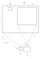
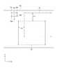
図1は、本実施形態に係る画像投影システム1および投影対象101を示す模式図であり、図2は、画像投影システム1の概略構成を示すブロック図である。
本実施形態に係る画像投影システム1は、図1に示すように、プロジェクター2と、プロジェクター2に接続された分光カメラ3と、を備えている。
この画像投影システム1は、本発明の投影位置検出装置を含んで構成されており、プロジェクター2により壁面などの投影対象101に投影される投影画像Ipの位置を、分光カメラ3により撮像された分光画像に基づいて制御するものである。An embodiment of the present invention will be described below with reference to the drawings.
FIG. 1 is a schematic diagram showing an
As shown in FIG. 1, the
The
[プロジェクター2の構成]
プロジェクター2は、図2に示すように、表示部21、レンズ調整機構22および制御部23を備える。この他、プロジェクター2は、図示を省略するが、当該プロジェクター2を構成する電子部品に電力を供給する電源装置や、冷却対象を冷却する冷却装置等を備える。[Configuration of Projector 2]
As shown in FIG. 2, the projector 2 includes a
表示部21は、制御部23から入力される駆動信号に応じた画像を形成および投射する。この表示部21は、光源211、液晶パネル212および投射レンズ213を備える。
光源211は、液晶パネル212の画像形成領域を照明する。このような光源211としては、超高圧水銀ランプ等の光源ランプ、および、当該光源ランプから出射された光を一方向に揃えて反射させる反射鏡を有する構成を採用できる他、LED(Light Emitting Diode)およびLD(Laser Diode)等の固体光源を有する構成を例示できる。
液晶パネル212は、上記駆動信号に応じて駆動して、光源211から入射される光を変調する光変調装置である。The
The
The
投射レンズ213は、液晶パネル212にて形成された画像を、スクリーンの被投射面上に拡大投射する投射光学装置である。この投射レンズ213は、鏡筒と、当該鏡筒内に配置された複数のレンズとを有する組レンズを例示できる。このような複数のレンズの1つとして、投射レンズ213は、入射された画像を拡大/縮小して被投射面に投射するズームレンズ213Aを備え、当該ズームレンズ213Aは、投射レンズ213の光軸に沿って進退する。 The
レンズ調整機構22は、投射レンズ213を、当該投射レンズ213の光軸に対して直交するX方向、および、前記光軸およびX方向のそれぞれに直交するY方向に移動させ、投射位置を調整させる。また、レンズ調整機構22は、投射レンズ213のズームレンズ213Aを、当該投射レンズ213の光軸に沿うZ方向に移動させ、投射画像を拡大/縮小させる。
すなわち、レンズ調整機構22は、投射レンズ213の光軸をX方向移動させるXシフト部221と、投射レンズ213の光軸をY方向に移動させるYシフト部222と、ズームレンズ213AをZ方向に移動させるズーム部223と、を備える。The lens adjustment mechanism 22 moves the
That is, the lens adjustment mechanism 22 moves the optical axis of the
ここで、投射レンズ213の光軸が+Y側に移動されると、投影画像Ipは+Y側に移動される。同様に、投射レンズ213の光軸が−Y側に移動されると、投影画像Ipは、−Y側に移動される。
また、投射レンズ213が+X側に移動されると、投影画像Ipは、+X側に移動される。同様に、投射レンズ213が−X側に移動されると、投影画像Ipは、−X側に移動される。
さらに、レンズ調整機構22により、ズームレンズ213AがZ方向に一方側に移動されて画角が広がると、投影画像Ipのサイズは大きくなる。一方、ズームレンズ213AがZ方向の他方側に移動されて画角が狭まると、投影画像Ipのサイズは小さくなる。Here, when the optical axis of the
Moreover, when the
Further, when the lens adjustment mechanism 22 moves the
このレンズ調整機構22の具体的な構成は、特に限定されないが、例えば、投射レンズ213をX方向に移動可能に保持するX軸ガイドと、投射レンズ213をY方向に移動可能に保持するY軸ガイドと、投射レンズ213の内部でズームレンズ213AをZ方向に移動させるZ軸ガイドと、を備える。各軸ガイドには、投射レンズ213またはズームレンズ213Aを駆動させる駆動力を供給するステッピングモーターが設けられる。この例では、レンズ調整機構22は、制御部23からのレンズ駆動信号に基づいて、各軸に対応したステッピングモーターを所定量駆動させることで、投射レンズ213またはズームレンズ213Aを移動させる。 The specific configuration of the lens adjustment mechanism 22 is not particularly limited, but, for example, an X-axis guide that holds the
制御部23は、表示部21を含むプロジェクター2の装置全体の動作を制御する。この制御部23は、CPU(Central Processing Unit)、ROM(Read Only Memory)およびRAM(Random Access Memory)等が実装された回路基板として構成されている。
そして、制御部23では、当該CPUがROMに記憶されたプログラムを実行することで、画像処理部231、表示制御部232、レンズ制御部233および投影位置制御部240として機能する。また、制御部23は、投影画像Ipの初期位置などを記憶する記憶部234を含んでいる。The control unit 23 controls the operation of the entire apparatus of the projector 2 including the
Then, in the control unit 23, the CPU executes a program stored in the ROM to function as the
画像処理部231は、外部から受信された画像データ(画像信号を含む)を処理し、当該画像データに基づいて1画面分の画像をフレームメモリー(図示省略)に描画する。
表示制御部232は、画像処理部231にて描画された画像を適宜読み出し、液晶パネル212を順次駆動させて、当該画像を形成させる。
レンズ制御部233は、レンズ調整機構22の動作を制御する。
記憶部234は、後述する投影画像Ipの初期設定などを記憶する。The
The
The
The
投影位置制御部240は、分光カメラ3により撮像された分光画像を解析し、解析結果に基づいてレンズ制御部233または画像処理部231に対して補正指示を出力する。これにより、投影位置制御部240は、投影対象101における投影画像Ipの投影位置等を制御する。この投影位置制御部240は、分光カメラ3と共に投影位置検出装置100を構成している。また、投影位置制御部240は、図3に示すように、スペクトル演算部241、特徴点検出部242、投影位置算出部243および補正指示部244を含んで構成される。 The projection
[分光カメラ3の構成]
分光カメラ3は、図2に示すように、近赤外光源31と、入射光学系32と、波長可変干渉フィルター33と、撮像素子34と、カメラ制御部35と、を含んで構成されている。
近赤外光源31は、分光カメラ3による撮像範囲に対して、近赤外域の光を照射する光源である。[Structure of the spectroscopic camera 3]
As shown in FIG. 2, the
The near-infrared
図4は、入射光学系32、波長可変干渉フィルター33および撮像素子34の各構成を示す模式図である。
入射光学系32は、例えばテレセントリック光学系等により構成され、光軸と主光線とが平行または略平行となるように入射光を波長可変干渉フィルター33および撮像素子34に導く。
波長可変干渉フィルター33は、ファブリーペローエタロンフィルターであり、互いに対向する一対の反射膜331,332と、これらの反射膜331,332の間の距離を変更可能な静電アクチュエーター333(本発明のギャップ変更部)とを備えて構成される。この波長可変干渉フィルター33は、静電アクチュエーター333への印加電圧が制御されることで、反射膜331,332を透過する光の波長(分光波長)が変更可能となる。
撮像素子34は、例えばCCD(Charge Coupled Device)やCMOS(Complementary Metal Oxide Semiconductor)等のイメージセンサーにより構成され、波長可変干渉フィルター33を透過した画像光を撮像する。本実施形態の分光カメラ3では、撮像素子34の各画素において、それぞれ波長可変干渉フィルター33を透過した光が入射される。FIG. 4 is a schematic diagram showing each configuration of the incident
The incident
The variable
The
カメラ制御部35は、CPU(Central Processing Unit)および内蔵メモリー等を含んで構成された集積回路である。カメラ制御部35は、CPUが内蔵メモリーに記録されたコンピュータープログラムを読み込み実行させることで、波長切替部351および撮像制御部352として機能する。また、カメラ制御部35は、記憶部353を含んで構成される。
なお、記憶部353には、波長可変干渉フィルター33を透過させる光の波長と静電アクチュエーター333への指令値とを互いに対応付けた駆動テーブルが記録されている。The
In the
波長切替部351は、駆動テーブルに基づいて、波長可変干渉フィルター33の静電アクチュエーター333に入力する指令値を変更する。
撮像制御部352は、撮像素子34の各画素から出力された受光信号(スペクトル情報)を取得して分光画像を得る。The
The
分光カメラ3は、取得した分光画像をプロジェクター2に送信可能に構成されている。具体的には、分光カメラ3は、プロジェクター2に対して、電波や赤外線等を用いて無線接続されてもよいし、ケーブル線等により有線接続されてもよい。 The
[画像投影システム1の初期設定]
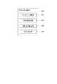
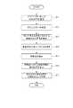
画像投影システム1の初期設定について、図5のフローチャートを参照して説明する。画像投影システム1の初期設定では、本実施形態の投影位置検出方法を利用する。なお、以下の説明において、プロジェクター2は、常設展示の画像を投影するものであり、投影対象101は、一様な色で彩色された平坦な壁面であるとする。[Initial setting of image projection system 1]
Initial setting of the
まず、プロジェクター2および分光カメラ3をそれぞれ設置する(ステップS11)。
具体的には、例えばユーザーが、投影対象101に投影される投影画像Ipを確認しながら、投影画像Ipが所望位置に所望サイズで表示されるように、プロジェクター2を設置する。また、例えばユーザーは、投影対象101に投影された投影画像Ipを含む所定範囲が撮像範囲となるように、分光カメラ3を設置する。
ここで、分光カメラ3の撮像範囲には、投影画像Ipだけでなく、マーカーMが含まれるものとする。本実施形態のマーカーMは、図1に示すように投影対象101である壁面に設置された矩形のプレート(施設の案内プレート等)である。ただし、本発明はこれに限られず、マーカーMは、投影対象101である壁面にみられる塗料のムラ、染み、または傷等であってもよい。
その後、プロジェクター2は、投影画像Ipを投影開始する(ステップS12)。なお、プロジェクター2は、ステップS11から投影画像Ipの投影を継続してもよい。First, the projector 2 and the
Specifically, for example, the user installs the projector 2 so that the projection image Ip is displayed at a desired position and in a desired size while checking the projection image Ip projected on the
Here, it is assumed that the imaging range of the
After that, the projector 2 starts projecting the projection image Ip (step S12). The projector 2 may continue projecting the projection image Ip from step S11.
次に、分光カメラ3は、互いに異なる波長に対応する複数の分光画像を撮像する(ステップS13;撮像ステップ)。
このとき、近赤外光源31は、分光カメラ3の撮像範囲に対して、750nm〜950nmの近赤外光を照射する。
また、波長切替部351は、駆動テーブルから指令値を順に読み出し、波長可変干渉フィルター33の静電アクチュエーター333に順に入力する。これにより、波長可変干渉フィルター33の透過波長は、予め設定された複数の波長(目標波長)に順次変更される。なお、目標波長は、可視光〜近赤外光の範囲(例えば680nm〜880nm)であって、20nm刻みに設定されている。
また、撮像素子34は、撮像制御部352に制御されることにより、波長可変干渉フィルター33の透過波長が目標波長に設定される毎に撮像を行う。これにより、各目標波長に対応する分光画像が撮像される。Next, the
At this time, the near infrared
In addition, the
Further, the
次に、スペクトル演算部241は、分光カメラ3から複数の分光画像を取得し、複数の分光画像に基づいて各画素の分光スペクトルを演算する(ステップS14;スペクトル演算ステップ)。これにより、図6に示すような解析画像Iaが生成される。
図6に示す解析画像Iaは、各画素の分光スペクトルに基づいて、複数の画素領域に区分される。
ここで、投影画像Ipは、可視光により投影される画像であるため、680nm付近の波長で最も反射強度が高くなる。このため、解析画像Iaにおいて680nm付近の波長で最大強度となる画素領域を、投影画像領域R1とする。
また、投影画像領域R1の周囲において、投影画像領域R1の分光スペクトルとは異なる分光スペクトルを示す画素領域を、背景領域R2とする。
また、背景領域R2により囲われる領域であって、投影画像領域R1および背景領域R2とはそれぞれ異なる分光スペクトルを示す画素領域を、マーカー領域R3とする。Next, the
The analysis image Ia shown in FIG. 6 is divided into a plurality of pixel regions based on the spectrum of each pixel.
Here, since the projection image Ip is an image projected by visible light, the reflection intensity is highest at a wavelength near 680 nm. Therefore, in the analysis image Ia, the pixel area having the maximum intensity at the wavelength near 680 nm is set as the projection image area R1.
In addition, a pixel area around the projection image area R1 that exhibits a spectrum different from the spectrum of the projection image area R1 is referred to as a background area R2.
Also, a pixel region surrounded by the background region R2 and showing a spectrum different from that of the projection image region R1 and the background region R2 is referred to as a marker region R3.
特徴点検出部242は、解析画像Iaにおけるマーカー領域R3の境界線を検出して当該境界線の角部Cm1〜Cm4を導出する。そして、角部Cm1〜Cm4の4点に対する重心を特徴点Gとして検出する(ステップS15;特徴点検出ステップ)。 The feature
次に、投影位置算出部243は、解析画像Iaにおける投影画像領域R1の境界線を検出して当該境界線の角部Cp1〜Cp4を導出する。そして、特徴点Gに対する投影画像Ipの相対位置として、特徴点Gを原点とする角部Cp1〜Cp4の座標(Xa1,Ya1)〜(Xa4,Ya4)を算出する(ステップS16;投影位置算出ステップ)。 Next, the projection
その後、投影位置算出部243は、ステップS16で算出した座標(Xa1,Ya1)〜(Xa4,Ya4)を、投影画像Ipの初期位置として記憶部234に記憶させる(ステップS17)。
以上により、画像投影システム1の初期設定が終了する。After that, the projection
With the above, the initial setting of the
[画像投影システム1の動作]
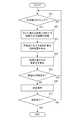
画像投影システム1の動作について、図7のフローチャートを参照して説明する。なお、図7のフローチャートは、プロジェクター2が投影画像Ipを投影開始することにより開始される。[Operation of the image projection system 1]
The operation of the
まず、分光カメラ3は、現在時刻が位置検出タイミングであるか否かを判断し(ステップS21)、Yesと判断した場合は次のステップS22に進み、Noと判断した場合は、Yesと判断するまで待機する。なお、位置検出タイミングは、例えば一定時間毎に設定されている。 First, the
次に、分光カメラ3は、互いに異なる波長に対応する複数の分光画像を撮像する(ステップS22)。投影位置制御部240は、撮像された複数の分光画像に基づいて、特徴点Gに対する投影画像Ipの相対位置、すなわち、特徴点Gを原点とする角部Cp1〜Cp4の座標(Xb1,Yb1)〜(Xb4,Yb4)を算出する(ステップS23)。
なお、ステップS22は、上述したステップS13と同様であり、ステップS23は、上述したステップS14〜ステップS16と同様である。Next, the
Note that step S22 is similar to step S13 described above, and step S23 is similar to step S14 to step S16 described above.
次に、補正指示部244は、ステップS23で算出された座標(Xb1,Yb1)〜(Xb4,Yb4)と、記憶部234に記憶された初期位置(Xa1,Ya1)〜(Xa4,Ya4)とを比較し、初期位置に対する変動量(ΔX1,ΔY1)〜(ΔX4,ΔY4)を算出する(ステップS24)。 Next, the
次に、補正指示部244は、ステップS24で算出された変動量(ΔX1,ΔY1)〜(ΔX4,ΔY4)が、X座標およびY座標のそれぞれについて、予め設定された閾値内であるか否かを判断する(ステップS25)。
変動量(ΔX1,ΔY1)〜(ΔX4,ΔY4)が、X座標およびY座標の両方について閾値内であると判断された場合(ステップS25;Yes)、ステップS21に戻る。
一方、変動量(ΔX1,ΔY1)〜(ΔX4,ΔY4)が、X座標およびY座標の少なくとも一方について閾値内ではないと判断された場合(ステップS25;No)、ステップS26に進む。Next, the
When it is determined that the variation amounts (ΔX1, ΔY1) to (ΔX4, ΔY4) are within the threshold values for both the X coordinate and the Y coordinate (step S25; Yes), the process returns to step S21.
On the other hand, when it is determined that the variation amounts (ΔX1, ΔY1) to (ΔX4, ΔY4) are not within the threshold values for at least one of the X coordinate and the Y coordinate (step S25; No), the process proceeds to step S26.
次に、補正指示部244は、変動量(ΔX1,ΔY1)〜(ΔX4,ΔY4)に基づいて、投影画像Ipの位置、サイズまたは形状に関して初期状態からのズレが生じているかを判断し、判断結果に基づいてレンズ制御部233または画像処理部231に補正指示を出力する(ステップS26)。 Next, the
例えば、投影画像Ipが初期位置からY方向およびX方向にずれている場合の解析画像Iaを図8に例示する。なお、図8では、初期位置の投影画像領域R1を破線で示し、現在の投影画像領域R1を実線で示している。
図8に示す例において、変動量ΔX1〜ΔX4は互いに等しい値(図8中のΔX)であり、変動量ΔY1〜ΔY4は、互いに等しい値(図8中のΔY)である。このような場合、補正指示部244は、投影画像Ipに位置ずれが生じたと判断し、レンズ制御部233に対して変動量(ΔX,ΔY)に基づく補正指示を出力する。この補正指示が入力されたレンズ制御部233は、変動量ΔXに基づいてXシフト部221を制御し、変動量ΔYに基づいてYシフト部222を制御する。これにより、Xシフト部221およびYシフト部222は、投影画像Ipの位置が初期位置に近づくように、投射レンズ213をX方向およびY方向に移動させる。すなわち、投影画像Ipは、一定の投影位置を保つように制御される。For example, FIG. 8 illustrates an analysis image Ia when the projection image Ip deviates from the initial position in the Y direction and the X direction. In FIG. 8, the projection image region R1 at the initial position is shown by a broken line, and the current projection image region R1 is shown by a solid line.
In the example shown in FIG. 8, the fluctuation amounts ΔX1 to ΔX4 are equal to each other (ΔX in FIG. 8), and the fluctuation amounts ΔY1 to ΔY4 are equal to each other (ΔY in FIG. 8). In such a case, the
なお、補正指示部244は、投影画像Ipにサイズ変動が生じたと判断した場合には、レンズ制御部233に対して変動量(ΔX1,ΔY1)〜(ΔX4,ΔY4)に基づく補正指示を出力する。レンズ制御部233は、補正指示に基づいてズーム部223を制御することにより、投影画像Ipのサイズを初期状態に近づける。
また、補正指示部244は、投影画像Ipの形状が変動したと判断した場合には、画像処理部231に対して変動量(ΔX1,ΔY1)〜(ΔX4,ΔY4)に基づく補正指示を出力する。画像処理部231は、補正指示に基づいて投影画像Ipのデータを補正することにより、投影画像Ipの形状を初期状態に近づける。If the
When the
プロジェクター2の電源を切るなど、投影が終了した場合(ステップS27:Yes)には、上述のフローを終了する。一方、投影が継続する場合(ステップS27:No)には、ステップS21に戻り、上述のフローを繰り返す。 When the projection is finished, such as turning off the power of the projector 2 (step S27: Yes), the above-described flow is finished. On the other hand, when the projection continues (step S27: No), the process returns to step S21 and the above-described flow is repeated.
[本実施形態の効果]
以上説明した本実施形態に係る投影位置検出装置100および画像投影システム1によれば、以下の効果を奏することができる。
(1)本実施形態の投影位置検出装置100は、投影対象101に投影された投影画像Ipを含む撮像範囲からの光を受光し、互いに異なる波長に対応する複数の分光画像を撮像する分光カメラ3と、複数の分光画像に基づいて各画素の分光スペクトルを演算するスペクトル演算部241と、画素の分光スペクトルに基づいて撮像範囲における特徴点Gを検出する特徴点検出部242と、特徴点Gに対する投影画像Ipの相対位置を算出する投影位置算出部243と、を備える。
このような構成によれば、分光カメラ3の撮像範囲に検出される特徴点Gが、投影画像Ipの投影位置を算出するための基準となる。このため、投影対象101の種類に限られずに、投影画像Ipの投影位置を設定できる。よって、設置場所の振動や人の接触等により投影画像Ipの投影位置がずれた場合には、このズレを容易に検出できる。[Effects of this embodiment]
According to the projection
(1) The projection
With such a configuration, the characteristic point G detected in the imaging range of the
(2)本実施形態において、分光カメラ3は、互いに対向する一対の反射膜331,332および一対の反射膜331,332の間のギャップの寸法を変更する静電アクチュエーター333を有する波長可変干渉フィルター33と、波長可変干渉フィルター33を透過した光を撮像する撮像素子34と、を備える。
このような構成では、撮像素子34の同一の画素で複数の波長の光を受光するため、撮像範囲における特徴点Gを高精度かつ高分解能で検出することができる。(2) In the present embodiment, the
With such a configuration, since the same pixel of the
(3)本実施形態において、分光カメラ3は、近赤外域の波長に対応する分光画像を撮像する。
ここで、従来技術である特許文献1に記載のシステムでは、一般的なカメラを利用している。このため、暗い空間で撮像された撮像画像は不鮮明となり、このような撮像画像に基づいてスクリーンの角部を検出することは困難である。すなわち、暗い空間で投影画像の投影位置を検出することは困難である。
これに対して、本実施形態では、近赤外域の波長に対応する分光画像を撮像し、この分光画像に基づいて投影画像Ipの投影位置を検出する。近赤外域の波長は、対象物の組成による光の反射性の違いを可視化できるため、暗い空間であっても投影画像Ipの投影位置を好適に検出できる。(3) In the present embodiment, the
Here, in the system described in
On the other hand, in the present embodiment, a spectral image corresponding to a wavelength in the near infrared region is captured, and the projection position of the projection image Ip is detected based on this spectral image. The wavelength in the near-infrared region makes it possible to visualize the difference in light reflectivity depending on the composition of the object, so that the projection position of the projection image Ip can be suitably detected even in a dark space.
(4)本実施形態の分光カメラ3は、投影対象101に対して近赤外域の波長を含む光を照射する近赤外光源31をさらに備える。
このような構成によれば、上述したように、暗い空間であっても投影画像Ipの投影位置をより好適に検出できる。また、近赤外域の波長光は、人の目に見えないため、投影画像Ipの色合いが変化することがない。また、照明によって明暗のコントラストを落とすこともなく、投影画像Ipを鮮明に見せることができる。(4) The
With such a configuration, as described above, the projection position of the projection image Ip can be detected more preferably even in a dark space. Further, since the wavelength light in the near infrared region is invisible to the human eye, the hue of the projected image Ip does not change. Further, the projected image Ip can be made to appear clear without lowering the contrast of light and dark by the illumination.
(5)本実施形態の画像投影システム1は、上述の投影位置検出装置100と、投影対象101に対して投影画像Ipを投射する投射レンズ213と、投射レンズ213の光軸調整またはズーム調整を行うレンズ調整機構22と、特徴点Gに対する投影画像Ipの相対位置の変動量に基づいて、レンズ調整機構22を制御するレンズ制御部233と、を備える。
このような構成によれば、投影画像Ipに位置またはサイズが一定になるように制御することができる。(5) The
With such a configuration, it is possible to control the position or size of the projected image Ip to be constant.
(6)本実施形態の画像投影システム1は、上述の投影位置検出装置100と、特徴点Gに対する投影画像Ipの相対位置の変動量に基づいて、投影画像Ipを補正する画像処理部231と、を備える。
このような構成によれば、投影画像Ipの形状が一定になるように制御することができる。(6) The
With such a configuration, the shape of the projected image Ip can be controlled to be constant.
なお、従来技術として、パターン画像を投影対象に投影して当該パターン画像を撮像することにより、投影画像のパラメーターを補正する手法が存在する(例えば特開2008−287426号公報参照)。しかし、このような従来技術では、パターン画像を投影するために、本来の投影画像の投影を中断しなくてはならない。
これに対して、本実施形態では、投影画像Ipの投影を中断することなく、投影画像Ipの投影位置を制御することができる。As a conventional technique, there is a method of correcting a parameter of a projection image by projecting the pattern image on a projection target and capturing the pattern image (see, for example, Japanese Patent Laid-Open No. 2008-287426). However, in such a conventional technique, in order to project the pattern image, the projection of the original projected image must be interrupted.
On the other hand, in the present embodiment, the projection position of the projection image Ip can be controlled without interrupting the projection of the projection image Ip.
[変形例]
本発明は前述の実施形態に限定されるものではなく、本発明の目的を達成できる範囲での変形、改良等は本発明に含まれるものである。[Modification]
The present invention is not limited to the above-described embodiments, and modifications, improvements, etc. within the scope of achieving the object of the present invention are included in the present invention.
(変形例1)
前記実施形態では、マーカー領域R3の角部Cm1〜Cm4の重心を特徴点Gとして検出しているが、本発明はこれに限られない。
例えば、マーカー領域R3の角部Cm1〜Cm4をそれぞれ特徴点として検出し、これらの特徴点に対する投影画像領域R1の角部Cp1〜Cp4の相対位置をそれぞれ算出してもよい。
あるいは、検出されたマーカー領域R3の角部Cm1〜Cm4のうちいずれか1つを特徴点として検出してもよい。(Modification 1)
In the above embodiment, the center of gravity of the corners Cm1 to Cm4 of the marker region R3 is detected as the feature point G, but the present invention is not limited to this.
For example, the corners Cm1 to Cm4 of the marker region R3 may be detected as feature points, and the relative positions of the corners Cp1 to Cp4 of the projection image region R1 with respect to these feature points may be calculated.
Alternatively, any one of the corners Cm1 to Cm4 of the detected marker region R3 may be detected as a feature point.
(変形例2)
前記実施形態では、矩形のプレートをマーカーMとして利用しているが、本発明はこれに限られない。
例えば、マーカーMは、投影対象101である壁面にみられる塗料のムラ、染み、または傷等であってもよい。このような場合、特徴点の検出については、一般的な画像処理の技術を利用できる。その一例として、染みを形成するエッジの内接円または外接円の中心を特徴点として検出してもよい。(Modification 2)
In the above embodiment, the rectangular plate is used as the marker M, but the present invention is not limited to this.
For example, the marker M may be unevenness, stains, scratches, or the like of the paint on the wall surface that is the
(変形例3)
前記実施形態では、投影画像Ipの投影位置として、投影画像領域R1の4つの角部Cp1〜Cp4の座標を算出しているが、本発明はこれに限られない。
例えば、大きなズレを想定しない場合には、投影画像領域R1の4つの角部Cp1〜Cp4のうち、少なくとも1つの角部の座標を算出してもよい。
また、投影画像Ipの投影位置として、投影画像領域R1の角部Cp1〜Cp4の重心を利用してもよい。
あるいは、投影画像Ipの投影位置として、投影画像領域R1の境界線の任意の点を利用してもよい。(Modification 3)
In the above embodiment, the coordinates of the four corners Cp1 to Cp4 of the projection image region R1 are calculated as the projection position of the projection image Ip, but the present invention is not limited to this.
For example, when a large deviation is not assumed, the coordinates of at least one corner of the four corners Cp1 to Cp4 of the projection image region R1 may be calculated.
Further, the center of gravity of the corners Cp1 to Cp4 of the projection image region R1 may be used as the projection position of the projection image Ip.
Alternatively, an arbitrary point on the boundary line of the projection image region R1 may be used as the projection position of the projection image Ip.
(変形例4)
前記実施形態では、分光カメラ3が近赤外域の波長に対応する分光画像を撮像しているが、紫外域の波長に対応する分光画像を撮像してもよい。また、分光カメラ3は、投影対象101に対して紫外域の波長を含む光を照射する光源を備えていてもよい。紫外光は、近赤外光と同様、人の目に見えないため、投影画像Ipの色合いが変化することがない。(Modification 4)
In the above embodiment, the
(変形例5)
前記実施形態では、投影画像Ipの位置およびサイズをレンズ調整機構22で制御し、投影画像Ipの形状を画像処理部231で制御しているが、本発明はこれに限られない。例えば、投影画像Ipがプロジェクター2の投影可能な範囲よりも小さい領域に投影される画像である場合、画像処理部231によって投影画像Ipの位置およびサイズを制御してもよい。(Modification 5)
In the above embodiment, the position and size of the projected image Ip are controlled by the lens adjustment mechanism 22 and the shape of the projected image Ip is controlled by the
(変形例6)
前記実施形態では、分光カメラ3が波長可変干渉フィルター33を有しているが、他の分光フィルターを有していてもよい。(Modification 6)
In the above embodiment, the
(変形例7)
前記実施形態では、プロジェクター2と分光カメラ3とが別々に構成されているが、これらは一体に構成されてもよい。(Modification 7)
In the above embodiment, the projector 2 and the
1…画像投影システム、100…投影位置検出装置、101…投影対象、2…プロジェクター、21…表示部、211…光源、212…液晶パネル、213…投射レンズ、213A…ズームレンズ、22…レンズ調整機構、221…Xシフト部、222…Yシフト部、223…ズーム部、23…制御部、231…画像処理部、232…表示制御部、233…レンズ制御部、234…記憶部、240…投影位置制御部、241…スペクトル演算部、242…特徴点検出部、243…投影位置算出部、244…補正指示部、3…分光カメラ、31…近赤外光源、32…入射光学系、33…波長可変干渉フィルター、331…反射膜、333…静電アクチュエーター、34…撮像素子、35…カメラ制御部、351…波長切替部、352…撮像制御部、353…記憶部、G…特徴点、Ia…解析画像、Ip…投影画像、M…マーカー、R1…投影画像領域、R2…背景領域、R3…マーカー領域。 DESCRIPTION OF
Claims (7)
Translated fromJapanese複数の前記分光画像に基づいて各画素の分光スペクトルを演算するスペクトル演算部と、
前記画素の前記分光スペクトルに基づいて前記撮像範囲における特徴点を検出する特徴点検出部と、
前記特徴点に対する前記投影画像の相対位置を算出する投影位置算出部と、を備える
ことを特徴とする投影位置検出装置。A spectroscopic camera that receives light from an imaging range including a projection image projected on a projection target and that captures a plurality of spectroscopic images corresponding to mutually different wavelengths,
A spectrum calculation unit that calculates a spectrum of each pixel based on the plurality of spectral images;
A feature point detection unit that detects a feature point in the imaging range based on the spectral spectrum of the pixel,
A projection position calculating unit that calculates a relative position of the projection image with respect to the feature point.
前記分光カメラは、
互いに対向する一対の反射膜および前記一対の反射膜の間のギャップの寸法を変更するギャップ変更部を有する波長可変干渉フィルターと、
前記波長可変干渉フィルターを透過した光を撮像する撮像素子と、を備える
ことを特徴とする投影位置検出装置。The projection position detection device according to claim 1,
The spectroscopic camera is
A wavelength tunable interference filter having a pair of reflecting films facing each other and a gap changing unit for changing the dimension of the gap between the pair of reflecting films,
An image pickup device for picking up an image of light that has passed through the variable wavelength interference filter.
前記分光カメラは、近赤外域の波長に対応する前記分光画像を撮像する
ことを特徴とする投影位置検出装置。The projection position detection device according to claim 1 or 2,
The projection position detection device, wherein the spectroscopic camera captures the spectroscopic image corresponding to a wavelength in the near infrared region.
前記投影対象に対して近赤外域の波長を含む光を照射する光源をさらに備える
ことを特徴とする投影位置検出装置。The projection position detection device according to claim 3,
The projection position detection device further comprising a light source that irradiates the projection target with light having a wavelength in the near infrared region.
前記投影対象に対して前記投影画像を投射する投射レンズと、
前記投射レンズの光軸調整またはズーム調整を行うレンズ調整機構と、
前記特徴点に対する前記投影画像の前記相対位置の変動量に基づいて、前記レンズ調整機構を制御するレンズ制御部と、を備える
ことを特徴とする画像投影システム。A projection position detecting device according to any one of claims 1 to 4,
A projection lens that projects the projection image onto the projection target;
A lens adjustment mechanism for performing optical axis adjustment or zoom adjustment of the projection lens,
An image projection system, comprising: a lens control unit that controls the lens adjustment mechanism based on a variation amount of the relative position of the projection image with respect to the feature point.
前記特徴点に対する前記投影画像の前記相対位置の変動量に基づいて、前記投影画像を補正する画像処理部と、を備える
ことを特徴とする画像投影システム。A projection position detecting device according to any one of claims 1 to 4,
An image processing system that corrects the projection image based on a variation amount of the relative position of the projection image with respect to the feature point.
複数の前記分光画像に基づいて各画素の分光スペクトルを演算するスペクトル演算ステップと、
前記画素の前記分光スペクトルに基づいて前記撮像範囲における特徴点を検出する特徴点検出ステップと、
前記特徴点に対する前記投影画像の相対位置を算出する投影位置算出ステップと、を含む
ことを特徴とする投影位置検出方法。An imaging step of receiving light from an imaging range including a projection image projected on a projection target and imaging a plurality of spectral images corresponding to mutually different wavelengths,
A spectrum calculation step of calculating a spectrum of each pixel based on the plurality of spectral images,
A characteristic point detecting step of detecting a characteristic point in the imaging range based on the spectral spectrum of the pixel;
A projection position calculating step of calculating a relative position of the projection image with respect to the feature point.
Priority Applications (2)
| Application Number | Priority Date | Filing Date | Title |
|---|---|---|---|
| JP2019013984AJP7318215B2 (en) | 2019-01-30 | 2019-01-30 | Image projection system and projection position detection method |
| US16/775,333US11146767B2 (en) | 2019-01-30 | 2020-01-29 | Projection position detection device, image projection system, and projection position detection method |
Applications Claiming Priority (1)
| Application Number | Priority Date | Filing Date | Title |
|---|---|---|---|
| JP2019013984AJP7318215B2 (en) | 2019-01-30 | 2019-01-30 | Image projection system and projection position detection method |
Publications (2)
| Publication Number | Publication Date |
|---|---|
| JP2020123800Atrue JP2020123800A (en) | 2020-08-13 |
| JP7318215B2 JP7318215B2 (en) | 2023-08-01 |
Family
ID=71731760
Family Applications (1)
| Application Number | Title | Priority Date | Filing Date |
|---|---|---|---|
| JP2019013984AActiveJP7318215B2 (en) | 2019-01-30 | 2019-01-30 | Image projection system and projection position detection method |
Country Status (2)
| Country | Link |
|---|---|
| US (1) | US11146767B2 (en) |
| JP (1) | JP7318215B2 (en) |
Families Citing this family (1)
| Publication number | Priority date | Publication date | Assignee | Title |
|---|---|---|---|---|
| US12372348B2 (en) | 2023-04-13 | 2025-07-29 | Meta Platforms Technologies, Llc | Dynamic profilometric imaging using multiscale patterns |
Citations (6)
| Publication number | Priority date | Publication date | Assignee | Title |
|---|---|---|---|---|
| JP2006102360A (en)* | 2004-10-08 | 2006-04-20 | Matsushita Electric Ind Co Ltd | Biological information presentation device |
| JP2008287171A (en)* | 2007-05-21 | 2008-11-27 | Funai Electric Co Ltd | Projection type image display device |
| JP2015087441A (en)* | 2013-10-29 | 2015-05-07 | セイコーエプソン株式会社 | Electro-optic device and method for driving electro-optic device |
| JP2015179182A (en)* | 2014-03-19 | 2015-10-08 | セイコーエプソン株式会社 | projector, and display state adjustment method |
| JP2016033489A (en)* | 2014-07-31 | 2016-03-10 | セイコーエプソン株式会社 | Spectral image acquisition device and reception wavelength acquisition method |
| JP2018137284A (en)* | 2017-02-20 | 2018-08-30 | ソニーセミコンダクタソリューションズ株式会社 | Sensor, solid-state imaging device, and electronic device |
Family Cites Families (7)
| Publication number | Priority date | Publication date | Assignee | Title |
|---|---|---|---|---|
| JP4090386B2 (en) | 2003-05-13 | 2008-05-28 | シャープ株式会社 | projector |
| JP4906586B2 (en) | 2007-05-16 | 2012-03-28 | 三菱電機株式会社 | Distortion correction apparatus and program |
| JP5521855B2 (en)* | 2009-09-10 | 2014-06-18 | 株式会社リコー | Projection image area detection device |
| JP6037375B2 (en) | 2012-05-29 | 2016-12-07 | 国立大学法人豊橋技術科学大学 | Image projection apparatus and image processing method |
| US10775605B2 (en)* | 2016-06-16 | 2020-09-15 | Intel Corporation | Combined biometrics capture system with ambient free IR |
| US9992464B1 (en)* | 2016-11-11 | 2018-06-05 | Christie Digital Systems Usa, Inc. | Method and system for screen correction |
| US11368657B2 (en)* | 2017-09-28 | 2022-06-21 | Disney Enterprises, Inc. | Light field based projector calibration method and system |
- 2019
- 2019-01-30JPJP2019013984Apatent/JP7318215B2/enactiveActive
- 2020
- 2020-01-29USUS16/775,333patent/US11146767B2/enactiveActive
Patent Citations (6)
| Publication number | Priority date | Publication date | Assignee | Title |
|---|---|---|---|---|
| JP2006102360A (en)* | 2004-10-08 | 2006-04-20 | Matsushita Electric Ind Co Ltd | Biological information presentation device |
| JP2008287171A (en)* | 2007-05-21 | 2008-11-27 | Funai Electric Co Ltd | Projection type image display device |
| JP2015087441A (en)* | 2013-10-29 | 2015-05-07 | セイコーエプソン株式会社 | Electro-optic device and method for driving electro-optic device |
| JP2015179182A (en)* | 2014-03-19 | 2015-10-08 | セイコーエプソン株式会社 | projector, and display state adjustment method |
| JP2016033489A (en)* | 2014-07-31 | 2016-03-10 | セイコーエプソン株式会社 | Spectral image acquisition device and reception wavelength acquisition method |
| JP2018137284A (en)* | 2017-02-20 | 2018-08-30 | ソニーセミコンダクタソリューションズ株式会社 | Sensor, solid-state imaging device, and electronic device |
Also Published As
| Publication number | Publication date |
|---|---|
| US11146767B2 (en) | 2021-10-12 |
| US20200244936A1 (en) | 2020-07-30 |
| JP7318215B2 (en) | 2023-08-01 |
Similar Documents
| Publication | Publication Date | Title |
|---|---|---|
| RU2585661C2 (en) | Projector and projector control method | |
| US8038303B2 (en) | Projection apparatus and optical ranging method | |
| CN103309141B (en) | The control method of projecting apparatus and projecting apparatus | |
| US11188170B2 (en) | Image display apparatus and method for controlling the same | |
| CN110463191B (en) | Projector and control method of projector | |
| WO2016052030A1 (en) | Projection-type display device | |
| WO2013121712A2 (en) | Projector and method of controlling projector | |
| JP2006047334A (en) | Projector apparatus and zooming control method | |
| JP3792679B2 (en) | Projector having a projection surface distance measuring device | |
| US11889238B2 (en) | Projection apparatus, projection method, and control program | |
| JP7318215B2 (en) | Image projection system and projection position detection method | |
| JP5845566B2 (en) | Projector and projector control method | |
| JP5845565B2 (en) | Projector and projector control method | |
| JP5309828B2 (en) | projector | |
| JP6347126B2 (en) | Projector and projector control method | |
| JP6119902B2 (en) | Projector and projector control method | |
| JP2021092734A (en) | Image projection device and method for controlling the same | |
| JP2012108232A (en) | Electronic device | |
| JPWO2018173559A1 (en) | Projector with detection function | |
| JP3772885B2 (en) | Projector with trapezoidal distortion correction means | |
| JP2005242089A (en) | Luminance measuring device, luminance adjusting device and projector for projector | |
| KR20120054741A (en) | Display apparatus and control method thereof | |
| JP2013186406A (en) | Spatial light modulator, projector, and projection image control method |
Legal Events
| Date | Code | Title | Description |
|---|---|---|---|
| A621 | Written request for application examination | Free format text:JAPANESE INTERMEDIATE CODE: A621 Effective date:20211209 | |
| A977 | Report on retrieval | Free format text:JAPANESE INTERMEDIATE CODE: A971007 Effective date:20221214 | |
| A131 | Notification of reasons for refusal | Free format text:JAPANESE INTERMEDIATE CODE: A131 Effective date:20221221 | |
| A521 | Request for written amendment filed | Free format text:JAPANESE INTERMEDIATE CODE: A523 Effective date:20230214 | |
| TRDD | Decision of grant or rejection written | ||
| A01 | Written decision to grant a patent or to grant a registration (utility model) | Free format text:JAPANESE INTERMEDIATE CODE: A01 Effective date:20230620 | |
| A61 | First payment of annual fees (during grant procedure) | Free format text:JAPANESE INTERMEDIATE CODE: A61 Effective date:20230703 | |
| R150 | Certificate of patent or registration of utility model | Ref document number:7318215 Country of ref document:JP Free format text:JAPANESE INTERMEDIATE CODE: R150 |