JP2020121571A - Method of fabricating three-dimensional object with removable support structure - Google Patents
Method of fabricating three-dimensional object with removable support structureDownload PDFInfo
- Publication number
- JP2020121571A JP2020121571AJP2020081822AJP2020081822AJP2020121571AJP 2020121571 AJP2020121571 AJP 2020121571AJP 2020081822 AJP2020081822 AJP 2020081822AJP 2020081822 AJP2020081822 AJP 2020081822AJP 2020121571 AJP2020121571 AJP 2020121571A
- Authority
- JP
- Japan
- Prior art keywords
- support structure
- dimensional
- dimensional object
- layer
- manufacturing
- Prior art date
- Legal status (The legal status is an assumption and is not a legal conclusion. Google has not performed a legal analysis and makes no representation as to the accuracy of the status listed.)
- Pending
Links
- 238000004519manufacturing processMethods0.000titleclaimsabstractdescription113
- 229920000642polymerPolymers0.000claimsabstractdescription133
- 238000000034methodMethods0.000claimsabstractdescription50
- 230000008021depositionEffects0.000claimsabstractdescription30
- 238000001816coolingMethods0.000claimsabstractdescription8
- 239000010410layerSubstances0.000claimsdescription278
- 239000000463materialSubstances0.000claimsdescription73
- 239000003795chemical substances by applicationSubstances0.000claimsdescription64
- 238000000151depositionMethods0.000claimsdescription44
- 238000007639printingMethods0.000claimsdescription35
- 239000007787solidSubstances0.000claimsdescription18
- 239000004094surface-active agentSubstances0.000claimsdescription16
- 239000000853adhesiveSubstances0.000claimsdescription15
- 230000001070adhesive effectEffects0.000claimsdescription15
- 239000000975dyeSubstances0.000claimsdescription14
- 230000015572biosynthetic processEffects0.000claimsdescription10
- 239000012943hotmeltSubstances0.000claimsdescription10
- 239000013047polymeric layerSubstances0.000claimsdescription9
- 239000012080ambient airSubstances0.000claimsdescription7
- 239000004014plasticizerSubstances0.000claimsdescription7
- 229920001223polyethylene glycolPolymers0.000claimsdescription7
- 238000003475laminationMethods0.000claimsdescription6
- 239000002861polymer materialSubstances0.000claimsdescription6
- 229920002545silicone oilPolymers0.000claimsdescription6
- 229920001971elastomerPolymers0.000claimsdescription5
- 150000002148estersChemical class0.000claimsdescription5
- 229930195733hydrocarbonNatural products0.000claimsdescription5
- 150000002430hydrocarbonsChemical class0.000claimsdescription5
- 239000003921oilSubstances0.000claimsdescription5
- 239000005060rubberSubstances0.000claimsdescription5
- 239000002904solventSubstances0.000claimsdescription5
- 238000002844meltingMethods0.000claimsdescription4
- 230000008018meltingEffects0.000claimsdescription4
- 239000012782phase change materialSubstances0.000claimsdescription4
- 229920001451polypropylene glycolPolymers0.000claimsdescription4
- 239000007850fluorescent dyeSubstances0.000claimsdescription3
- 230000008569processEffects0.000abstractdescription21
- 239000000976inkSubstances0.000description114
- 239000000203mixtureSubstances0.000description20
- 239000007788liquidSubstances0.000description13
- 239000004615ingredientSubstances0.000description9
- WKBPZYKAUNRMKP-UHFFFAOYSA-N1-[2-(2,4-dichlorophenyl)pentyl]1,2,4-triazoleChemical compoundC=1C=C(Cl)C=C(Cl)C=1C(CCC)CN1C=NC=N1WKBPZYKAUNRMKP-UHFFFAOYSA-N0.000description8
- -1polybutylene terephthalatePolymers0.000description8
- 238000010586diagramMethods0.000description7
- 230000008901benefitEffects0.000description6
- 238000002474experimental methodMethods0.000description6
- CHBRHODLKOZEPZ-UHFFFAOYSA-NClotiazepamChemical compoundS1C(CC)=CC2=C1N(C)C(=O)CN=C2C1=CC=CC=C1ClCHBRHODLKOZEPZ-UHFFFAOYSA-N0.000description5
- 238000011960computer-aided designMethods0.000description5
- 239000004205dimethyl polysiloxaneSubstances0.000description5
- 238000012986modificationMethods0.000description5
- 230000004048modificationEffects0.000description5
- 229920000435poly(dimethylsiloxane)Polymers0.000description5
- 230000008859changeEffects0.000description4
- 230000000295complement effectEffects0.000description4
- 239000007789gasSubstances0.000description4
- 239000003365glass fiberSubstances0.000description4
- 239000000126substanceSubstances0.000description4
- 229920003171Poly (ethylene oxide)Polymers0.000description3
- DNIAPMSPPWPWGF-UHFFFAOYSA-NPropylene glycolChemical compoundCC(O)CODNIAPMSPPWPWGF-UHFFFAOYSA-N0.000description3
- 239000000654additiveSubstances0.000description3
- 238000005137deposition processMethods0.000description3
- 238000013461designMethods0.000description3
- 238000005516engineering processMethods0.000description3
- 239000003292glueSubstances0.000description3
- 238000010030laminatingMethods0.000description3
- 229920005989resinPolymers0.000description3
- 239000011347resinSubstances0.000description3
- 238000003860storageMethods0.000description3
- XLYOFNOQVPJJNP-UHFFFAOYSA-NwaterSubstancesOXLYOFNOQVPJJNP-UHFFFAOYSA-N0.000description3
- CUDYYMUUJHLCGZ-UHFFFAOYSA-N2-(2-methoxypropoxy)propan-1-olChemical compoundCOC(C)COC(C)COCUDYYMUUJHLCGZ-UHFFFAOYSA-N0.000description2
- 229920000089Cyclic olefin copolymerPolymers0.000description2
- LYCAIKOWRPUZTN-UHFFFAOYSA-NEthylene glycolChemical compoundOCCOLYCAIKOWRPUZTN-UHFFFAOYSA-N0.000description2
- 229920000106Liquid crystal polymerPolymers0.000description2
- 239000004977Liquid-crystal polymers (LCPs)Substances0.000description2
- 239000004696Poly ether ether ketoneSubstances0.000description2
- 239000004952PolyamideSubstances0.000description2
- 239000002202Polyethylene glycolSubstances0.000description2
- WCUXLLCKKVVCTQ-UHFFFAOYSA-MPotassium chlorideChemical compound[Cl-].[K+]WCUXLLCKKVVCTQ-UHFFFAOYSA-M0.000description2
- XECAHXYUAAWDEL-UHFFFAOYSA-Nacrylonitrile butadiene styreneChemical compoundC=CC=C.C=CC#N.C=CC1=CC=CC=C1XECAHXYUAAWDEL-UHFFFAOYSA-N0.000description2
- 229920000122acrylonitrile butadiene styrenePolymers0.000description2
- 239000004676acrylonitrile butadiene styreneSubstances0.000description2
- 230000000996additive effectEffects0.000description2
- 239000003054catalystSubstances0.000description2
- 238000006243chemical reactionMethods0.000description2
- 239000003086colorantSubstances0.000description2
- 230000032798delaminationEffects0.000description2
- 230000000694effectsEffects0.000description2
- 238000011156evaluationMethods0.000description2
- 238000010100freeform fabricationMethods0.000description2
- 238000001540jet depositionMethods0.000description2
- 230000003287optical effectEffects0.000description2
- 239000000049pigmentSubstances0.000description2
- 229920003023plasticPolymers0.000description2
- 239000004033plasticSubstances0.000description2
- 229920006112polar polymerPolymers0.000description2
- 229920000747poly(lactic acid)Polymers0.000description2
- 229920000058polyacrylatePolymers0.000description2
- 229920002647polyamidePolymers0.000description2
- 229920001610polycaprolactonePolymers0.000description2
- 229920002530polyetherether ketonePolymers0.000description2
- 229940068918polyethylene glycol 400Drugs0.000description2
- 229920000098polyolefinPolymers0.000description2
- 238000000110selective laser sinteringMethods0.000description2
- 238000004513sizingMethods0.000description2
- 238000012360testing methodMethods0.000description2
- 229920002725thermoplastic elastomerPolymers0.000description2
- 239000010409thin filmSubstances0.000description2
- 230000007704transitionEffects0.000description2
- 229920003169water-soluble polymerPolymers0.000description2
- JNYAEWCLZODPBN-JGWLITMVSA-N(2r,3r,4s)-2-[(1r)-1,2-dihydroxyethyl]oxolane-3,4-diolChemical compoundOC[C@@H](O)[C@H]1OC[C@H](O)[C@H]1OJNYAEWCLZODPBN-JGWLITMVSA-N0.000description1
- WRIDQFICGBMAFQ-UHFFFAOYSA-N(E)-8-Octadecenoic acidNatural productsCCCCCCCCCC=CCCCCCCC(O)=OWRIDQFICGBMAFQ-UHFFFAOYSA-N0.000description1
- LQJBNNIYVWPHFW-UHFFFAOYSA-N20:1omega9c fatty acidNatural productsCCCCCCCCCCC=CCCCCCCCC(O)=OLQJBNNIYVWPHFW-UHFFFAOYSA-N0.000description1
- 2380000101463D printingMethods0.000description1
- QSBYPNXLFMSGKH-UHFFFAOYSA-N9-HeptadecensaeureNatural productsCCCCCCCC=CCCCCCCCC(O)=OQSBYPNXLFMSGKH-UHFFFAOYSA-N0.000description1
- 102000008186CollagenHuman genes0.000description1
- 108010035532CollagenProteins0.000description1
- 239000004641Diallyl-phthalateSubstances0.000description1
- 102000016942ElastinHuman genes0.000description1
- 108010014258ElastinProteins0.000description1
- 239000004593EpoxySubstances0.000description1
- 101000691618Homo sapiens Inactive phospholipase C-like protein 1Proteins0.000description1
- 102100026207Inactive phospholipase C-like protein 1Human genes0.000description1
- MGJKQDOBUOMPEZ-UHFFFAOYSA-NN,N'-dimethylureaChemical compoundCNC(=O)NCMGJKQDOBUOMPEZ-UHFFFAOYSA-N0.000description1
- ZQPPMHVWECSIRJ-UHFFFAOYSA-NOleic acidNatural productsCCCCCCCCC=CCCCCCCCC(O)=OZQPPMHVWECSIRJ-UHFFFAOYSA-N0.000description1
- 239000005642Oleic acidSubstances0.000description1
- 239000004698PolyethyleneSubstances0.000description1
- 239000004642PolyimideSubstances0.000description1
- 229920001214Polysorbate 60Polymers0.000description1
- 239000004793PolystyreneSubstances0.000description1
- 239000004372Polyvinyl alcoholSubstances0.000description1
- 239000004820Pressure-sensitive adhesiveSubstances0.000description1
- OFOBLEOULBTSOW-UHFFFAOYSA-NPropanedioic acidNatural productsOC(=O)CC(O)=OOFOBLEOULBTSOW-UHFFFAOYSA-N0.000description1
- NWGKJDSIEKMTRX-AAZCQSIUSA-NSorbitan monooleateChemical compoundCCCCCCCC\C=C/CCCCCCCC(=O)OC[C@@H](O)[C@H]1OC[C@H](O)[C@H]1ONWGKJDSIEKMTRX-AAZCQSIUSA-N0.000description1
- 239000013543active substanceSubstances0.000description1
- 230000001464adherent effectEffects0.000description1
- 239000003570airSubstances0.000description1
- 239000003513alkaliSubstances0.000description1
- 239000002280amphoteric surfactantSubstances0.000description1
- 239000003945anionic surfactantSubstances0.000description1
- JUPQTSLXMOCDHR-UHFFFAOYSA-Nbenzene-1,4-diol;bis(4-fluorophenyl)methanoneChemical compoundOC1=CC=C(O)C=C1.C1=CC(F)=CC=C1C(=O)C1=CC=C(F)C=C1JUPQTSLXMOCDHR-UHFFFAOYSA-N0.000description1
- QUDWYFHPNIMBFC-UHFFFAOYSA-Nbis(prop-2-enyl) benzene-1,2-dicarboxylateChemical compoundC=CCOC(=O)C1=CC=CC=C1C(=O)OCC=CQUDWYFHPNIMBFC-UHFFFAOYSA-N0.000description1
- 238000007664blowingMethods0.000description1
- 230000001680brushing effectEffects0.000description1
- 238000004364calculation methodMethods0.000description1
- 125000002091cationic groupChemical group0.000description1
- 239000003093cationic surfactantSubstances0.000description1
- 229920001436collagenPolymers0.000description1
- 230000008094contradictory effectEffects0.000description1
- 229920001577copolymerPolymers0.000description1
- 230000007423decreaseEffects0.000description1
- 230000007547defectEffects0.000description1
- 230000001419dependent effectEffects0.000description1
- IRXRGVFLQOSHOH-UHFFFAOYSA-Ldipotassium;oxalateChemical compound[K+].[K+].[O-]C(=O)C([O-])=OIRXRGVFLQOSHOH-UHFFFAOYSA-L0.000description1
- 238000004090dissolutionMethods0.000description1
- 229920002549elastinPolymers0.000description1
- 239000003995emulsifying agentSubstances0.000description1
- 239000003822epoxy resinSubstances0.000description1
- 230000007717exclusionEffects0.000description1
- 238000001125extrusionMethods0.000description1
- 239000010408filmSubstances0.000description1
- 238000009472formulationMethods0.000description1
- 230000006870functionEffects0.000description1
- 239000012767functional fillerSubstances0.000description1
- 238000000227grindingMethods0.000description1
- 239000012456homogeneous solutionSubstances0.000description1
- 239000000017hydrogelSubstances0.000description1
- WGCNASOHLSPBMP-UHFFFAOYSA-NhydroxyacetaldehydeNatural productsOCC=OWGCNASOHLSPBMP-UHFFFAOYSA-N0.000description1
- 239000011256inorganic fillerSubstances0.000description1
- 230000003993interactionEffects0.000description1
- 238000005495investment castingMethods0.000description1
- 239000002563ionic surfactantSubstances0.000description1
- QXJSBBXBKPUZAA-UHFFFAOYSA-Nisooleic acidNatural productsCCCCCCCC=CCCCCCCCCC(O)=OQXJSBBXBKPUZAA-UHFFFAOYSA-N0.000description1
- VZCYOOQTPOCHFL-UPHRSURJSA-Nmaleic acidChemical compoundOC(=O)\C=C/C(O)=OVZCYOOQTPOCHFL-UPHRSURJSA-N0.000description1
- 239000011976maleic acidSubstances0.000description1
- 150000002689maleic acidsChemical class0.000description1
- XJRBAMWJDBPFIM-UHFFFAOYSA-Nmethyl vinyl etherChemical compoundCOC=CXJRBAMWJDBPFIM-UHFFFAOYSA-N0.000description1
- 239000002736nonionic surfactantSubstances0.000description1
- ZQPPMHVWECSIRJ-KTKRTIGZSA-Noleic acidChemical compoundCCCCCCCC\C=C/CCCCCCCC(O)=OZQPPMHVWECSIRJ-KTKRTIGZSA-N0.000description1
- 150000002894organic compoundsChemical group0.000description1
- 239000012766organic fillerSubstances0.000description1
- 238000005498polishingMethods0.000description1
- 229920000848poly(L-lactide-ε-caprolactone)Polymers0.000description1
- 229920001606poly(lactic acid-co-glycolic acid)Polymers0.000description1
- 229940065514poly(lactide)Drugs0.000description1
- 229920002492poly(sulfone)Polymers0.000description1
- 229920001515polyalkylene glycolPolymers0.000description1
- 229920001707polybutylene terephthalatePolymers0.000description1
- 239000004632polycaprolactoneSubstances0.000description1
- 229920000515polycarbonatePolymers0.000description1
- 239000004417polycarbonateSubstances0.000description1
- 229920000647polyepoxidePolymers0.000description1
- 229920000728polyesterPolymers0.000description1
- 229920000139polyethylene terephthalatePolymers0.000description1
- 229920001721polyimidePolymers0.000description1
- 238000006116polymerization reactionMethods0.000description1
- 239000000244polyoxyethylene sorbitan monooleateSubstances0.000description1
- 235000010482polyoxyethylene sorbitan monooleateNutrition0.000description1
- 239000001818polyoxyethylene sorbitan monostearateSubstances0.000description1
- 235000010989polyoxyethylene sorbitan monostearateNutrition0.000description1
- 229940113124polysorbate 60Drugs0.000description1
- 229920000053polysorbate 80Polymers0.000description1
- 229940068968polysorbate 80Drugs0.000description1
- 229920002223polystyrenePolymers0.000description1
- 229920002635polyurethanePolymers0.000description1
- 239000004814polyurethaneSubstances0.000description1
- 229920002451polyvinyl alcoholPolymers0.000description1
- 229920000915polyvinyl chloridePolymers0.000description1
- 239000004800polyvinyl chlorideSubstances0.000description1
- 229920000036polyvinylpyrrolidonePolymers0.000description1
- 239000001267polyvinylpyrrolidoneSubstances0.000description1
- 235000013855polyvinylpyrrolidoneNutrition0.000description1
- 239000001103potassium chlorideSubstances0.000description1
- 235000011164potassium chlorideNutrition0.000description1
- 238000002360preparation methodMethods0.000description1
- 102000004196processed proteins & peptidesHuman genes0.000description1
- 108090000765processed proteins & peptidesProteins0.000description1
- 238000012545processingMethods0.000description1
- 102000004169proteins and genesHuman genes0.000description1
- 108090000623proteins and genesProteins0.000description1
- 150000003839saltsChemical group0.000description1
- 229920002050silicone resinPolymers0.000description1
- 150000003384small moleculesChemical group0.000description1
- 239000001509sodium citrateSubstances0.000description1
- NLJMYIDDQXHKNR-UHFFFAOYSA-Ksodium citrateChemical compoundO.O.[Na+].[Na+].[Na+].[O-]C(=O)CC(O)(CC([O-])=O)C([O-])=ONLJMYIDDQXHKNR-UHFFFAOYSA-K0.000description1
- 238000001228spectrumMethods0.000description1
- 238000006467substitution reactionMethods0.000description1
- 230000000153supplemental effectEffects0.000description1
- 239000012815thermoplastic materialSubstances0.000description1
- VZCYOOQTPOCHFL-UHFFFAOYSA-Ntrans-butenedioic acidNatural productsOC(=O)C=CC(O)=OVZCYOOQTPOCHFL-UHFFFAOYSA-N0.000description1
- 238000012795verificationMethods0.000description1
- 239000003021water soluble solventSubstances0.000description1
- 238000009736wettingMethods0.000description1
Images


Classifications
- B—PERFORMING OPERATIONS; TRANSPORTING
- B29—WORKING OF PLASTICS; WORKING OF SUBSTANCES IN A PLASTIC STATE IN GENERAL
- B29C—SHAPING OR JOINING OF PLASTICS; SHAPING OF MATERIAL IN A PLASTIC STATE, NOT OTHERWISE PROVIDED FOR; AFTER-TREATMENT OF THE SHAPED PRODUCTS, e.g. REPAIRING
- B29C64/00—Additive manufacturing, i.e. manufacturing of three-dimensional [3D] objects by additive deposition, additive agglomeration or additive layering, e.g. by 3D printing, stereolithography or selective laser sintering
- B29C64/40—Structures for supporting 3D objects during manufacture and intended to be sacrificed after completion thereof
- B—PERFORMING OPERATIONS; TRANSPORTING
- B29—WORKING OF PLASTICS; WORKING OF SUBSTANCES IN A PLASTIC STATE IN GENERAL
- B29C—SHAPING OR JOINING OF PLASTICS; SHAPING OF MATERIAL IN A PLASTIC STATE, NOT OTHERWISE PROVIDED FOR; AFTER-TREATMENT OF THE SHAPED PRODUCTS, e.g. REPAIRING
- B29C33/00—Moulds or cores; Details thereof or accessories therefor
- B29C33/56—Coatings, e.g. enameled or galvanised; Releasing, lubricating or separating agents
- B29C33/58—Applying the releasing agents
- B—PERFORMING OPERATIONS; TRANSPORTING
- B29—WORKING OF PLASTICS; WORKING OF SUBSTANCES IN A PLASTIC STATE IN GENERAL
- B29C—SHAPING OR JOINING OF PLASTICS; SHAPING OF MATERIAL IN A PLASTIC STATE, NOT OTHERWISE PROVIDED FOR; AFTER-TREATMENT OF THE SHAPED PRODUCTS, e.g. REPAIRING
- B29C33/00—Moulds or cores; Details thereof or accessories therefor
- B29C33/56—Coatings, e.g. enameled or galvanised; Releasing, lubricating or separating agents
- B29C33/60—Releasing, lubricating or separating agents
- B—PERFORMING OPERATIONS; TRANSPORTING
- B29—WORKING OF PLASTICS; WORKING OF SUBSTANCES IN A PLASTIC STATE IN GENERAL
- B29C—SHAPING OR JOINING OF PLASTICS; SHAPING OF MATERIAL IN A PLASTIC STATE, NOT OTHERWISE PROVIDED FOR; AFTER-TREATMENT OF THE SHAPED PRODUCTS, e.g. REPAIRING
- B29C64/00—Additive manufacturing, i.e. manufacturing of three-dimensional [3D] objects by additive deposition, additive agglomeration or additive layering, e.g. by 3D printing, stereolithography or selective laser sintering
- B29C64/10—Processes of additive manufacturing
- B29C64/106—Processes of additive manufacturing using only liquids or viscous materials, e.g. depositing a continuous bead of viscous material
- B29C64/118—Processes of additive manufacturing using only liquids or viscous materials, e.g. depositing a continuous bead of viscous material using filamentary material being melted, e.g. fused deposition modelling [FDM]
- B—PERFORMING OPERATIONS; TRANSPORTING
- B29—WORKING OF PLASTICS; WORKING OF SUBSTANCES IN A PLASTIC STATE IN GENERAL
- B29C—SHAPING OR JOINING OF PLASTICS; SHAPING OF MATERIAL IN A PLASTIC STATE, NOT OTHERWISE PROVIDED FOR; AFTER-TREATMENT OF THE SHAPED PRODUCTS, e.g. REPAIRING
- B29C64/00—Additive manufacturing, i.e. manufacturing of three-dimensional [3D] objects by additive deposition, additive agglomeration or additive layering, e.g. by 3D printing, stereolithography or selective laser sintering
- B29C64/20—Apparatus for additive manufacturing; Details thereof or accessories therefor
- B29C64/205—Means for applying layers
- B29C64/209—Heads; Nozzles
- B—PERFORMING OPERATIONS; TRANSPORTING
- B29—WORKING OF PLASTICS; WORKING OF SUBSTANCES IN A PLASTIC STATE IN GENERAL
- B29C—SHAPING OR JOINING OF PLASTICS; SHAPING OF MATERIAL IN A PLASTIC STATE, NOT OTHERWISE PROVIDED FOR; AFTER-TREATMENT OF THE SHAPED PRODUCTS, e.g. REPAIRING
- B29C64/00—Additive manufacturing, i.e. manufacturing of three-dimensional [3D] objects by additive deposition, additive agglomeration or additive layering, e.g. by 3D printing, stereolithography or selective laser sintering
- B29C64/30—Auxiliary operations or equipment
- B29C64/386—Data acquisition or data processing for additive manufacturing
- B29C64/393—Data acquisition or data processing for additive manufacturing for controlling or regulating additive manufacturing processes
- B—PERFORMING OPERATIONS; TRANSPORTING
- B33—ADDITIVE MANUFACTURING TECHNOLOGY
- B33Y—ADDITIVE MANUFACTURING, i.e. MANUFACTURING OF THREE-DIMENSIONAL [3-D] OBJECTS BY ADDITIVE DEPOSITION, ADDITIVE AGGLOMERATION OR ADDITIVE LAYERING, e.g. BY 3-D PRINTING, STEREOLITHOGRAPHY OR SELECTIVE LASER SINTERING
- B33Y10/00—Processes of additive manufacturing
- B—PERFORMING OPERATIONS; TRANSPORTING
- B33—ADDITIVE MANUFACTURING TECHNOLOGY
- B33Y—ADDITIVE MANUFACTURING, i.e. MANUFACTURING OF THREE-DIMENSIONAL [3-D] OBJECTS BY ADDITIVE DEPOSITION, ADDITIVE AGGLOMERATION OR ADDITIVE LAYERING, e.g. BY 3-D PRINTING, STEREOLITHOGRAPHY OR SELECTIVE LASER SINTERING
- B33Y50/00—Data acquisition or data processing for additive manufacturing
- B33Y50/02—Data acquisition or data processing for additive manufacturing for controlling or regulating additive manufacturing processes
- B—PERFORMING OPERATIONS; TRANSPORTING
- B33—ADDITIVE MANUFACTURING TECHNOLOGY
- B33Y—ADDITIVE MANUFACTURING, i.e. MANUFACTURING OF THREE-DIMENSIONAL [3-D] OBJECTS BY ADDITIVE DEPOSITION, ADDITIVE AGGLOMERATION OR ADDITIVE LAYERING, e.g. BY 3-D PRINTING, STEREOLITHOGRAPHY OR SELECTIVE LASER SINTERING
- B33Y80/00—Products made by additive manufacturing
Landscapes
- Engineering & Computer Science (AREA)
- Chemical & Material Sciences (AREA)
- Materials Engineering (AREA)
- Manufacturing & Machinery (AREA)
- Mechanical Engineering (AREA)
- Physics & Mathematics (AREA)
- Optics & Photonics (AREA)
Abstract
Description
Translated fromJapanese関連出願
本出願は、2016年8月30日に出願された米国仮出願第62/381,300号の優先権および恩典を主張する。上記出願の教示全体が、参照により本明細書に組み入れられる。Related Applications This application claims the priority and benefits of US Provisional Application No. 62/381,300, filed August 30, 2016. The entire teachings of the above application are incorporated herein by reference.
発明の背景
コンピュータ支援設計(CAD)ソリッドモデリングシステムの使用の増加に伴い、CAD出力データを三次元の物理的物体へ変換することを可能にする製造技術の新しい最先端領域が登場した。この技術は、一般に付加製造(例えば、固体自由形状製造または積層製造)と呼ばれ、層ごとおよびポイントごとに物体を構築する工程を伴う。市販の固体自由形状製造システムの例としては、光造形法(stereo lithography)、選択的レーザー焼結法、薄膜積層法(laminated object manufacturing)、および熱溶解積層法が挙げられる。固体自由形状製造システムの他の例は、当業者に公知である。BACKGROUND OF THE INVENTION With the increasing use of computer-aided design (CAD) solid modeling systems, a new frontier of manufacturing technology has emerged that allows the conversion of CAD output data into three-dimensional physical objects. This technique is commonly referred to as additive manufacturing (eg, solid freeform manufacturing or layered manufacturing) and involves the process of building objects layer by layer and point by point. Examples of commercially available solid freeform fabrication systems include stereolithography, selective laser sintering, laminated object manufacturing, and hot melt lamination. Other examples of solid freeform manufacturing systems are known to those of skill in the art.
三次元の自動的な物体形成は、CADデータベースの検証、美観の評価、設計の人間工学的チェック、工具および備品設計の支援、概念モデルおよび販売/マーケティングツールの作成、インベストメント鋳造用のパターンの生成、生産における技術変更の削減または排除、ならびに少量生産工程の提供において有用である。 3D automatic object formation, CAD database verification, aesthetic evaluation, design ergonomic checking, tool and equipment design assistance, conceptual model and sales/marketing tool creation, investment casting pattern generation It is useful in reducing or eliminating technological changes in production, and providing a small-scale production process.
付加製造プロセスの際、製造プロセス中に作られた支持構造体を取り外すことは時間および手間がかかる場合がある。支持構造体を取り外す様々な方法としては、支持体を破壊すること、液体媒体に支持材料を溶解させること、または支持材料を融解することが挙げられる。これらの方法は、パーツの表面上に欠陥をもたらす場合がある。更に、パーツは、研削または研磨などの後処理を必要とし得る。 During an additive manufacturing process, removing the support structure created during the manufacturing process can be time consuming and tedious. Various methods of removing the support structure include breaking the support, dissolving the support material in a liquid medium, or melting the support material. These methods can result in defects on the surface of the part. In addition, the parts may require post-treatment such as grinding or polishing.
いかなる追加的な後処理を必要とすることなく支持体から容易に取り外し可能である様々な三次元物体を生産することが可能な三次元製造方法および装置を提供することが望ましいであろう。本発明の局面は、このような三次元物体の製造を対象とする。三次元物体は、高解像度の色を有してもよい。 It would be desirable to provide a three-dimensional manufacturing method and apparatus that is capable of producing a variety of three-dimensional objects that can be easily removed from a support without the need for any additional post-treatment. Aspects of the invention are directed to manufacturing such three-dimensional objects. The three-dimensional object may have high resolution colors.
(a)(例えば、プロセッサを使用して)支持構造体を必要とする三次元物体の領域を仮想的に特定する工程;(b)(例えば、プロセッサを使用して)三次元物体のための支持構造体を仮想的に生成する工程;(c)(例えば、プロセッサを使用して)支持構造体および三次元物体を含むシーンを層へ仮想的にスライスする工程;(d)(例えば、プロセッサを使用して)支持構造体が三次元物体に隣接している各層の領域を特定する工程;(e)(例えば、印刷装置を使用して)支持構造体および/または物体のポリマー層を堆積させる工程;(f)(例えば、印刷装置を使用して)剥離剤を含む層を支持構造体または物体のポリマー層の少なくとも一部分の上に堆積させる工程;ならびに(g)(例えば、印刷装置を使用して)三次元物体および/または支持構造体の少なくとも1つのポリマー層を、剥離剤を含む層の上に堆積させる工程を含む、三次元製造方法が、本明細書において開示される。 (a) virtually identifying a region of the three-dimensional object requiring a support structure (e.g., using a processor); (b) for a three-dimensional object (e.g., using a processor) Virtually creating a support structure; (c) virtually slicing a scene containing the support structure and the three-dimensional object into layers (e.g., using a processor); (d) (e.g., processor). Identifying the area of each layer where the support structure is adjacent to the three-dimensional object (using (e.g.) and (e) depositing the polymer layer of the support structure and/or the object (using, for example, a printing device). (F) depositing a layer containing a release agent (eg, using a printing device) on at least a portion of the polymeric layer of the support structure or object; and (g) (eg, using a printing device). Disclosed herein is a three-dimensional manufacturing method comprising the step of depositing at least one polymer layer of a three-dimensional object and/or a support structure (using) onto a layer containing a release agent.
ある特定の局面において、剥離剤は、装置の少なくとも1つの印刷ヘッドを介して堆積されるインクである。ある特定の態様において、剥離剤は、シリコーン油、油および炭化水素、ポリエチレングリコール、ポリプロピレングリコール、エステル、界面活性剤、水溶性ゴム、可塑剤中または揮発性溶媒中の固体剥離物質、低粘着性接着剤、ならびにこれらの組み合わせからなる群より選択される材料により製剤化される。剥離剤は、非反応性化学作用、反応性化学作用、または相変化材料に基づいて選択されてもよい。 In certain aspects, the release agent is an ink that is deposited through at least one printhead of the device. In certain embodiments, release agents include silicone oils, oils and hydrocarbons, polyethylene glycols, polypropylene glycols, esters, surfactants, water soluble rubbers, solid release materials in plasticizers or volatile solvents, low tack. It is formulated with a material selected from the group consisting of adhesives, as well as combinations thereof. Release agents may be selected based on non-reactive chemistries, reactive chemistries, or phase change materials.
ある特定の態様において、三次元物体と支持構造体との間の特定された領域は、二次元画像ファイルに変換される。いくつかの局面において、支持構造体はポリマー材料から形成され、支持構造体ポリマー材料は、三次元物体を形成するために使用されるポリマー材料と類似するかまたは同じものである。他の局面において、支持構造体はポリマー材料から形成され、支持構造体ポリマー材料は、三次元物体を形成するために使用されるポリマー材料とは異なる。 In certain aspects, the identified regions between the three-dimensional object and the support structure are converted into a two-dimensional image file. In some aspects, the support structure is formed from a polymeric material, and the support structure polymeric material is similar to or the same as the polymeric material used to form the three-dimensional object. In other aspects, the support structure is formed from a polymeric material, and the support structure polymeric material is different than the polymeric material used to form the three-dimensional object.
ある特定の局面において、支持構造体は外側インク層を有し、外側インク層は三次元物体を形成するポリマー材料に可溶性である少なくとも1つの成分を含む。 In certain aspects, the support structure has an outer ink layer, the outer ink layer including at least one component that is soluble in the polymeric material that forms the three-dimensional object.
本発明のある特定の局面に従うと、外側インク層の少なくとも1つの成分は、支持構造体のポリマー材料が溶けるのを加速させてもよい。 According to certain aspects of the invention, at least one component of the outer ink layer may accelerate dissolution of the polymeric material of the support structure.
いくつかの局面において、仮想空間が、シーンをスライスしている時に支持構造体と三次元物体との間に生成される。空間の厚さは、ポリマー層の厚さの0.1%〜100%であってもよい。あるいは、空間の厚さは、ポリマー層の厚さの約50%である。空間の厚さは、三次元物体の曲率に基づいて調節されてもよい。 In some aspects, virtual space is created between the support structure and the three-dimensional object while slicing the scene. The thickness of the spaces may be 0.1% to 100% of the thickness of the polymer layer. Alternatively, the space thickness is about 50% of the polymer layer thickness. The thickness of the space may be adjusted based on the curvature of the three-dimensional object.
ある特定の態様において、支持構造体、三次元物体、または支持構造体および三次元物体のフィラメント密度は、三次元製造プロセス中に調節される。フィラメント密度の変動は、公称フィラメント密度の0.5〜1.7の範囲内であってもよい。 In certain embodiments, the support structure, the three-dimensional object, or the filament density of the support structure and the three-dimensional object is adjusted during the three-dimensional manufacturing process. The variation in filament density may be within the range of 0.5 to 1.7 of the nominal filament density.
いくつかの局面において、三次元物体および/または支持構造体のポリマー層の少なくとも1つは、剥離剤を含む層の堆積の前に強制冷却される。ポリマー層の少なくとも1つは、周囲空気もしくは外気を適用することによってまたは圧縮気体を適用することによって強制冷却されてもよい。 In some aspects, at least one of the polymeric layers of the three-dimensional object and/or the support structure is force cooled prior to deposition of the layer containing the release agent. At least one of the polymer layers may be forced cooled by applying ambient or ambient air or by applying compressed gas.
ある特定の局面において、三次元物体は、熱溶解積層法を使用して形成される。いくつかの態様において、剥離剤を含む層は、紫外線吸収色素または蛍光色素を含む。いくつかの局面において、剥離剤を含む層は、支持構造体が三次元物体に隣接している特定された領域で、三次元物体と支持構造体との間に堆積される。剥離剤の濃度は、三次元物体の曲率に基づいて調節されてもよい。 In one particular aspect, the three-dimensional object is formed using a hot melt deposition process. In some embodiments, the release agent-containing layer comprises a UV absorbing dye or a fluorescent dye. In some aspects, the release agent-containing layer is deposited between the three-dimensional object and the support structure at the identified region where the support structure is adjacent to the three-dimensional object. The concentration of the release agent may be adjusted based on the curvature of the three-dimensional object.
(a)三次元物体を形成する工程;および(b)三次元物体の形成中に、三次元物体に隣接する支持構造体を形成する工程を含み、剥離剤を含む層が、三次元物体と支持構造体との間に堆積される、(例えば、三次元プリンタの使用による)三次元製造方法もまた、本明細書において開示される。 (a) forming a three-dimensional object; and (b) including the step of forming a support structure adjacent to the three-dimensional object during the formation of the three-dimensional object, the layer containing a release agent, a three-dimensional object and Also disclosed herein are three-dimensional manufacturing methods (eg, by using a three-dimensional printer) that are deposited between the support structure.
(a)三次元物体を形成する工程;および(b)三次元物体の形成中に、三次元物体に隣接する支持構造体を形成する工程を含み、支持構造体および/または三次元物体の少なくとも1つの外側ポリマー層に強制冷却が適用される、(例えば、三次元プリンタの使用による)三次元製造方法もまた、本明細書において開示される。 (a) forming a three-dimensional object; and (b) including forming a support structure adjacent to the three-dimensional object during formation of the three-dimensional object, at least the support structure and/or the three-dimensional object. Also disclosed herein are three-dimensional manufacturing methods (eg, by use of a three-dimensional printer) where forced cooling is applied to one outer polymer layer.
(a)三次元物体を形成する工程;および(b)三次元物体の形成中に、三次元物体に隣接する支持構造体を形成する工程を含み、剥離剤を含む層が、三次元物体と支持構造体との間に堆積され、剥離剤が、2つの連続するポリマー層間の接着を妨げる、(例えば、三次元プリンタの使用による)三次元製造方法もまた、開示される。 (a) forming a three-dimensional object; and (b) including the step of forming a support structure adjacent to the three-dimensional object during the formation of the three-dimensional object, the layer containing a release agent, a three-dimensional object and Also disclosed is a three-dimensional manufacturing method (eg, through the use of a three-dimensional printer) in which a release agent deposited between the support structure prevents the adhesion between two consecutive polymer layers.
外側ポリマー層を有する三次元印刷された物体と;外側ポリマー層を有する三次元印刷された支持構造体と;三次元物体の外側ポリマー層と支持構造体の外側ポリマー層との間に堆積された、剥離剤を含む層と;を含む製品もまた、本明細書において開示される。 A three-dimensional printed object having an outer polymer layer; a three-dimensional printed support structure having an outer polymer layer; deposited between the outer polymer layer of the three-dimensional object and the outer polymer layer of the support structure Also disclosed herein are products that include, a layer that includes a release agent;
[本発明1001]
(a)プロセッサを使用して、支持構造体を必要とする三次元物体の領域を特定する工程;
(b)プロセッサを使用して、該三次元物体のための支持構造体を仮想的に生成する工程;
(c)プロセッサを使用して、該支持構造体および該三次元物体を含むシーンを層へ仮想的にスライスする工程;
(d)プロセッサを使用して、該支持構造体が該三次元物体に隣接している各層の領域を特定する工程;
(e)支持構造体および/または三次元物体のポリマー層を堆積させる印刷装置;
(f)剥離剤を含む層を該支持構造体および/または該三次元物体の該ポリマー層の少なくとも一部分の上に堆積させる印刷装置;ならびに
(g)該三次元物体および/または該支持構造体の少なくとも1つのポリマー層を、該剥離剤を含む該層の上に堆積させる印刷装置
を含む三次元製造方法。
[本発明1002]
剥離剤が、装置の少なくとも1つの印刷ヘッドを介して堆積されるインクである、本発明1001の三次元製造方法。
[本発明1003]
三次元物体と支持構造体に隣接している特定された領域が、二次元画像ファイルに変換される、本発明1001の三次元製造方法。
[本発明1004]
支持構造体がポリマー材料から形成され、該支持構造体ポリマー材料が、三次元物体を形成するために使用されるポリマー材料と同じものである、本発明1001の三次元製造方法。
[本発明1005]
支持構造体がポリマー材料から形成され、該支持構造体ポリマー材料が、三次元物体を形成するために使用されるポリマー材料とは異なる、本発明1001の三次元製造方法。
[本発明1006]
支持構造体が外側インク層を有し、該外側インク層が、三次元物体を形成するポリマー材料に可溶性である少なくとも1つの成分を含む、本発明1001の三次元製造方法。
[本発明1007]
外側インク層の前記少なくとも1つの成分が、支持構造体のポリマー材料が溶けるのを加速させる、本発明1006の三次元製造方法。
[本発明1008]
剥離剤が、シリコーン油、油および炭化水素、ポリエチレングリコール、ポリプロピレングリコール、エステル、界面活性剤、水溶性ゴム、可塑剤中または揮発性溶媒中の固体剥離物質、低粘着性接着剤、ならびにこれらの組み合わせからなる群より選択される材料により製剤化されている、本発明1001の三次元製造方法。
[本発明1009]
剥離剤が、非反応性化学作用、反応性化学作用、または相変化材料に基づく、本発明1001の三次元製造方法。
[本発明1010]
シーンをスライスしている時に支持構造体と三次元物体との間に空間が仮想的に生成される、本発明1001の三次元製造方法。
[本発明1011]
前記空間の厚さが、ポリマー層の厚さの0.1%〜100%である、本発明1010の三次元製造方法。
[本発明1012]
前記空間の厚さが、ポリマー層の厚さの約50%である、本発明1010の三次元製造方法。
[本発明1013]
前記空間の厚さが、三次元物体の曲率に基づいて調節される、本発明1010の三次元製造方法。
[本発明1014]
支持構造体、三次元物体、または支持構造体および三次元物体のフィラメント密度が、三次元製造プロセス中に調節される、本発明1001の三次元製造方法。
[本発明1015]
フィラメント密度の変動が、公称フィラメント密度の0.1〜2.0の範囲内である、本発明1014の三次元製造方法。
[本発明1016]
三次元物体および/または支持構造体の少なくとも1つのポリマー層が、剥離剤を含む層の堆積の前に強制冷却される、本発明1001の三次元製造方法。
[本発明1017]
前記少なくとも1つのポリマー層が、周囲空気もしくは外気を適用することによってまたは圧縮気体を適用することによって強制冷却される、本発明1016の三次元製造方法。
[本発明1018]
三次元物体が、熱溶解積層法を使用して形成される、本発明1001の三次元製造方法。
[本発明1019]
剥離剤を含む層が、紫外線吸収色素または蛍光色素を含む、本発明1001の三次元製造方法。
[本発明1020]
剥離剤を含む層が、支持構造体が三次元物体に隣接している特定された領域で、該三次元物体と該支持構造体との間に堆積される、本発明1001の三次元製造方法。
[本発明1021]
剥離剤の濃度が、三次元物体の曲率に基づいて調節される、本発明1001の三次元製造方法。
[本発明1022]
(a)三次元プリンタの使用により、三次元物体を形成する工程;および
(b)該三次元物体の形成中に、三次元プリンタの使用により、該三次元物体に隣接する支持構造体を形成する工程
を含み、
剥離剤を含む層が、該三次元物体と該支持構造体との間に堆積される、
三次元製造方法。
[本発明1023]
(a)三次元プリンタの使用により、三次元物体を形成する工程;および
(b)該三次元物体の形成中に、三次元プリンタの使用により、該三次元物体に隣接する支持構造体を形成する工程
を含み、
該支持構造体および/または該三次元物体の少なくとも1つの外側ポリマー層に強制冷却が適用される、
三次元製造方法。
[本発明1024]
(a)三次元プリンタの使用により、三次元物体を形成する工程;および
(b)該三次元物体の形成中に、三次元プリンタの使用により、該三次元物体に隣接する支持構造体を形成する工程
を含み、
剥離剤を含む層が、該三次元物体と該支持構造体との間に堆積され、該剥離剤が、2つの連続するポリマー層間の接着を妨げる、
三次元製造方法。
[本発明1025]
(a)外側ポリマー層を有する三次元印刷された物体と、
(b)外側ポリマー層を有する三次元印刷された支持構造体と、
(c)該三次元物体の該外側ポリマー層と該支持構造体の該外側ポリマー層との間に堆積された、剥離剤を含む層と
を含む製品。
上記考察した本発明の特徴および多くの他の特徴ならびに付随する利点は、本発明の以下の詳細な説明を参照することによってよりよく理解されるであろう。更に、ここで説明される様々な態様の特徴は、互いに排他的ではなく、様々な組み合わせおよび順序で存在することができることを理解すべきである。[Invention 1001]
(a) identifying a region of a three-dimensional object that requires a support structure using a processor;
(b) using a processor to virtually generate a support structure for the three-dimensional object;
(c) virtually slicing a scene containing the support structure and the three-dimensional object into layers using a processor;
(d) using a processor to identify the area of each layer where the support structure is adjacent to the three-dimensional object;
(e) a printing device for depositing a support structure and/or a polymer layer of a three-dimensional object;
(f) a printing device that deposits a layer containing a release agent on at least a portion of the polymeric layer of the support structure and/or the three-dimensional object; and
(g) A three-dimensional manufacturing method including a printing device in which at least one polymer layer of the three-dimensional object and/or the support structure is deposited on the layer containing the release agent.
[Invention 1002]
The three-dimensional manufacturing method of invention 1001, wherein the release agent is an ink deposited through at least one printhead of the device.
[Invention 1003]
The three-dimensional manufacturing method of the present invention 1001, wherein the specified region adjacent to the three-dimensional object and the support structure is converted into a two-dimensional image file.
[Invention 1004]
The three-dimensional manufacturing method of invention 1001, wherein the support structure is formed of a polymeric material, and the support structure polymeric material is the same polymeric material used to form the three-dimensional object.
[Invention 1005]
The three-dimensional manufacturing method of invention 1001, wherein the support structure is formed from a polymeric material, the support structure polymeric material being different than the polymeric material used to form the three-dimensional object.
[Invention 1006]
The three-dimensional manufacturing method of invention 1001 wherein the support structure has an outer ink layer, the outer ink layer comprising at least one component that is soluble in the polymeric material forming the three-dimensional object.
[Invention 1007]
The three-dimensional fabrication method of invention 1006, wherein said at least one component of the outer ink layer accelerates melting of the polymeric material of the support structure.
[Invention 1008]
Release agents include silicone oils, oils and hydrocarbons, polyethylene glycols, polypropylene glycols, esters, surfactants, water soluble rubbers, solid release materials in plasticizers or volatile solvents, low tack adhesives, and these The three-dimensional manufacturing method of the present invention 1001, which is formulated by a material selected from the group consisting of combinations.
[Invention 1009]
The three-dimensional manufacturing method of present invention 1001, wherein the release agent is based on non-reactive chemistry, reactive chemistry, or phase change material.
[Invention 1010]
The three-dimensional manufacturing method of present invention 1001, wherein a space is virtually generated between the support structure and the three-dimensional object while slicing the scene.
[Invention 1011]
The three-dimensional manufacturing method of the present invention 1010, wherein the thickness of the space is 0.1% to 100% of the thickness of the polymer layer.
[Invention 1012]
The three-dimensional manufacturing method of the present invention 1010, wherein the thickness of the space is about 50% of the thickness of the polymer layer.
[Invention 1013]
The three-dimensional manufacturing method of the present invention 1010, wherein the thickness of the space is adjusted based on the curvature of the three-dimensional object.
[Invention 1014]
The three-dimensional manufacturing method of invention 1001, wherein the filament density of the support structure, the three-dimensional object, or the support structure and the three-dimensional object is adjusted during the three-dimensional manufacturing process.
[Invention 1015]
The three-dimensional manufacturing method of the present invention 1014, wherein the fluctuation of the filament density is within the range of 0.1 to 2.0 of the nominal filament density.
[Invention 1016]
The three-dimensional fabrication method of invention 1001, wherein at least one polymer layer of the three-dimensional object and/or the support structure is force cooled prior to deposition of the layer containing the release agent.
[Invention 1017]
The three-dimensional manufacturing method of invention 1016, wherein said at least one polymer layer is forced cooled by applying ambient air or ambient air or by applying compressed gas.
[Invention 1018]
The three-dimensional manufacturing method of invention 1001, wherein the three-dimensional object is formed using a hot melt laminating method.
[Invention 1019]
The three-dimensional manufacturing method of the present invention 1001, wherein the layer containing a release agent contains an ultraviolet absorbing dye or a fluorescent dye.
[Invention 1020]
The three-dimensional manufacturing method of the invention 1001 wherein a layer comprising a release agent is deposited between the three-dimensional object and the support structure in a specified region where the support structure is adjacent to the three-dimensional object. ..
[Invention 1021]
The three-dimensional manufacturing method of the present invention 1001, wherein the concentration of the release agent is adjusted based on the curvature of the three-dimensional object.
[Invention 1022]
(a) forming a three-dimensional object by using a three-dimensional printer; and
(b) forming a support structure adjacent to the three-dimensional object by using a three-dimensional printer during formation of the three-dimensional object,
A layer containing a release agent is deposited between the three-dimensional object and the support structure,
Three-dimensional manufacturing method.
[Invention 1023]
(a) forming a three-dimensional object by using a three-dimensional printer; and
(b) forming a support structure adjacent to the three-dimensional object by using a three-dimensional printer during formation of the three-dimensional object,
Forced cooling is applied to at least one outer polymer layer of the support structure and/or the three-dimensional object,
Three-dimensional manufacturing method.
[Invention 1024]
(a) forming a three-dimensional object by using a three-dimensional printer; and
(b) forming a support structure adjacent to the three-dimensional object by using a three-dimensional printer during formation of the three-dimensional object,
A layer containing a release agent is deposited between the three-dimensional object and the support structure, the release agent preventing adhesion between two consecutive polymer layers.
Three-dimensional manufacturing method.
[Invention 1025]
(a) a three-dimensionally printed object having an outer polymer layer,
(b) a three-dimensionally printed support structure having an outer polymer layer,
(c) An article comprising a layer comprising a release agent deposited between the outer polymer layer of the three-dimensional object and the outer polymer layer of the support structure.
The features of the invention and many other features as well as the attendant advantages discussed above will be better understood with reference to the following detailed description of the invention. Furthermore, it should be understood that the features of the various aspects described herein are not mutually exclusive and may exist in various combinations and orders.
図面において、同様の参照符号は、概して、異なる図全体にわたって同じ部分を指す。また、図面は必ずしも一定の比率ではなく、本発明の原理を例示することに概して重点が置かれる。以下の説明において、本発明の様々な態様が、以下の図面を参照にして説明される。 In the drawings, like reference numbers generally refer to the same parts throughout the different views. Also, the drawings are not necessarily to scale and a general focus is on illustrating the principles of the invention. In the following description, various aspects of the present invention will be described with reference to the following drawings.
特許または出願書類は、カラーで作成された少なくとも1つの図面を含む。カラー図面を含むこの特許または特許出願刊行物の複写は、申請および必要な手数料の支払に応じて官庁によって提供されるであろう。 The patent or application file contains at least one drawing executed in color. Copies of this patent or patent application publication with color drawings will be provided by the Office upon request and payment of the necessary fee.
発明の詳細な説明
支持構造体から容易に取り外し可能である様々な三次元物体を生産することが可能な三次元製造方法および装置を提供することが望ましい。本発明のいくつかの局面に従うと、剥離層、または剥離剤を含む層が、製造される三次元物体と支持構造体との間に堆積される。三次元物体と支持構造体との間の仮想空間を、三次元製造ソフトウエアを使用して生成することができ、その空間は、製造時、特定された空間内に剥離層を堆積させる前に、拡大または縮小してもよい。三次元物体および/または支持構造体を形成するために使用されるポリマーのフィラメント密度は、公称フィラメント密度に対して調節(例えば、低減または増加)されてもよい。三次元物体および/または支持構造体の外側ポリマー層(複数可)は、強制冷却されてもよい。DETAILED DESCRIPTION OF THE INVENTION It is desirable to provide a three-dimensional manufacturing method and apparatus capable of producing a variety of three-dimensional objects that are easily removable from a support structure. According to some aspects of the invention, a release layer, or a layer containing a release agent, is deposited between the three-dimensional object to be manufactured and the support structure. A virtual space between the three-dimensional object and the support structure can be created using three-dimensional manufacturing software, which space is produced during manufacture before depositing the release layer in the specified space. , May be enlarged or reduced. The filament density of the polymer used to form the three-dimensional object and/or support structure may be adjusted (eg, reduced or increased) with respect to the nominal filament density. The outer polymer layer(s) of the three-dimensional object and/or the support structure may be force cooled.
本発明の更なる局面に従うと、説明された方法の1つまたは複数が、三次元物体の支持構造体からの剥離性を向上させるために組み合わされてもよい。例えば、剥離層が、支持構造体と三次元物体との間に堆積されてもよい。あるいは、剥離層が、支持構造体と三次元物体との間に堆積されてもよく、加えて、三次元物体および/または支持構造体の少なくとも1つのポリマー層が、強制冷却されてもよい。剥離層を支持構造体と三次元物体との間に堆積させることができ、物体および/または支持構造体を形成するために使用されるポリマーのフィラメント密度が、公称フィラメント密度に対して調節される。本明細書で開示される支持構造体取り外し方法のいくつかまたはすべての更なる特徴および利点は、以下の概要および例示的で非限定的な例の説明の恩恵を受けた当業者には明らかとなるであろう。 According to a further aspect of the present invention, one or more of the described methods may be combined to improve the releasability of the three-dimensional object from the support structure. For example, a release layer may be deposited between the support structure and the three-dimensional object. Alternatively, a release layer may be deposited between the support structure and the three-dimensional object, and in addition at least one polymer layer of the three-dimensional object and/or the support structure may be forced cooled. A release layer can be deposited between the support structure and the three-dimensional object, and the filament density of the polymer used to form the object and/or the support structure is adjusted relative to the nominal filament density. .. Additional features and advantages of some or all of the support structure removal methods disclosed herein will be apparent to those of ordinary skill in the art having benefit of the following summary and illustrative, non-limiting examples. Will be.
本明細書において使用される場合、「三次元製造」は、層ごとに三次元物体および/または支持構造体を構築する方法を指すために使用される。三次元製造は、三次元物体を形成するための、少なくとも1つのポリマー層を堆積させる工程と少なくとも1つのインク層を印刷する工程との組み合わせを指す。ポリマー層またはインク層は、堆積装置または印刷装置の少なくとも1回の通過、例えば1、2、3、4、5回、またはそれ以上の通過、によって形成される。通過の回数は、所望のインチ当りのドット数(dpi)によって決定されてもよい。少なくとも1つのポリマー層および少なくとも1つのインク層は、所望の構造および結果に応じて、任意の順番で堆積および印刷され得るが、2つのポリマー層の間への剥離層の導入は、分離可能となる2つの本体(例えば、支持構造体および三次元物体)間での二分化をもたらさなければならない。例えば、複数のポリマー層が、インク層を印刷する前に堆積されてもよい。いくつかの例では、ポリマー層およびインク層が、個々の層または複数の層ごとに互い違いになる。様々な三次元製造方法が、当技術分野において公知であり、熱溶解積層法、薄膜積層法、光造形法、および選択的レーザー焼結法が挙げられるが、これらに限定されない。 As used herein, "three-dimensional fabrication" is used to refer to a method of building a three-dimensional object and/or support structure layer by layer. Three-dimensional manufacturing refers to the combination of depositing at least one polymer layer and printing at least one ink layer to form a three-dimensional object. The polymer or ink layer is formed by at least one pass through the deposition or printing device, for example 1, 2, 3, 4, 5 or more passes. The number of passes may be determined by the desired number of dots per inch (dpi). The at least one polymer layer and the at least one ink layer can be deposited and printed in any order, depending on the desired structure and result, but the introduction of a release layer between the two polymer layers is separable. Must result in a dichotomy between the two bodies (eg, the support structure and the three-dimensional object). For example, multiple polymer layers may be deposited before printing the ink layer. In some examples, the polymer and ink layers are staggered in individual layers or layers. Various three-dimensional manufacturing methods are known in the art and include, but are not limited to, hot melt lamination, thin film lamination, stereolithography, and selective laser sintering.
様々な三次元堆積装置または三次元製造装置が、本明細書において説明される革新的な向上をもたらすように本発明の局面と関連して説明された製造方法を実行するために使用されてもよい。概して、本明細書において利用される三次元製造装置は、堆積装置および印刷装置を含む。いくつかの態様において、堆積装置は、熱溶解積層法のために使用されるものと類似する。いくつかの態様において、印刷装置は、層ごとの構築プロセスを利用することによって三次元ポリマー物体を構築する任意の固体自由形状製造装置と対になる。このような装置の非限定的な例としては、薄膜積層装置または三次元フォトポリマー装置が挙げられる。 A variety of three-dimensional deposition equipment or three-dimensional manufacturing equipment may also be used to carry out the manufacturing methods described in connection with aspects of the present invention to provide the innovative enhancements described herein. Good. Generally, the three-dimensional manufacturing apparatus utilized herein includes a deposition apparatus and a printing apparatus. In some embodiments, the deposition equipment is similar to that used for hot melt deposition. In some embodiments, the printing device is paired with any solid freeform fabrication device that builds a three-dimensional polymeric object by utilizing a layer-by-layer build process. Non-limiting examples of such devices include thin film laminating devices or three-dimensional photopolymer devices.
公知の熱溶解積層装置の一例を図1に示す。押出機アセンブリ12は、三次元物体16を形成するために、層ごとのプロセスで、構築プラットフォーム18上へポリマー14を吐出する。三次元物体16が完成すると、物体が構築プラットフォーム18から取り外されてもよく、新しいプロジェクトが開始され得る。 An example of a known hot melt laminating apparatus is shown in FIG. The
別の三次元製造装置の例が、米国特許第9,227,366号に記載され、その内容全体が参照により本明細書に組み入れられる。この三次元製造装置の概略図が、図2に示される。装置は、熱溶解積層法のために使用されるものと類似した堆積装置20ならびに印刷ヘッドおよびインク送出システム32を有した印刷装置30を含む。三次元製造装置は、構築プラットフォーム28上に三次元物体26を形成するために層ごとのプロセスでポリマー材料24を吐出する押出機アセンブリ22を含む。更に、製造装置は、印刷ヘッドおよびインク送出システム32を含み、構築プロセス中、印刷ヘッドおよびインク送出システムは、層ごとのプロセスで、三次元物体26上にインクを吐出する。 An example of another three-dimensional manufacturing apparatus is described in US Pat. No. 9,227,366, the entire contents of which are incorporated herein by reference. A schematic diagram of this three-dimensional manufacturing apparatus is shown in FIG. The apparatus includes a
堆積装置20は、ポリマー24を吐出する押出機アセンブリ22を含む。押出機アセンブリ22は、1つまたは複数のポリマー材料24(例えば、複数のポリマー)を吐出するための1つまたは複数の押出機ヘッド23を含んでもよい。いくつかの局面において、ポリマー材料24は、層ごとのプロセスで構築プラットフォーム28上に三次元物体26を形成する。 The
印刷装置30は、三次元製造装置を使用した任意の三次元物体26の生産中にインク34を堆積させるための印刷ヘッドおよびインク送出システム32を含む。印刷装置30は、1つまたは複数のインク34を吐出するための1つまたは複数の印刷ヘッド33を含んでもよい。印刷ヘッドおよびインク送出システム32は、製造プロセス中にインク34を層ごとに堆積させてもよい。
印刷ヘッドおよびインク送出システム32を有する印刷装置30は、押出機アセンブリ22を有する堆積装置20と同じ機械に取り付けられ、その結果、堆積装置20と共に移動する。いくつかの態様において、印刷装置30は、三次元製造装置に取り付けられる独立した可動式または固定式の機械に取り付けられる。更に他の態様において、印刷装置30は、堆積装置20と位置合わせされるが、堆積装置20に取り付けられない。 The
印刷装置30は、例えば、圧電印刷ヘッド、サーマル印刷ヘッド、MEMS印刷ヘッド、静電印刷ヘッド、またはこれらの組み合わせである印刷ヘッド33(複数可)を含む。いくつかの局面において、印刷装置30は、プロッタータイプの単一ノズルユニット、連続インクジェット、またはドロップオンデマンドシステムである印刷ヘッド33を含む。ある特定の局面において、1つまたは複数の印刷ヘッド33は、印刷装置30内に含まれる。他の局面において、印刷ヘッド33は、1つまたは複数のチャネルを含む。いくつかの態様において、印刷装置30は、ジェット式堆積方法を利用する。あるいは、印刷装置30は、ジェット式ではない堆積方法を利用する。例えば、印刷装置30は、例えば剥離剤の堆積のための押出ノズル、噴霧器、ブラッシングまたは毛細管を含んでもよい。
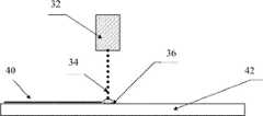
三次元物体50および/または支持構造体52を生産する三次元製造方法の例が、本明細書において提供される。三次元製造方法は、第1のポリマー層42を堆積させる工程、第1のポリマー層42の上に第1のインク層40を印刷する工程、第1のインク層40の上に第2のポリマー層42を堆積させる工程、および第2のポリマー層42の上に第2のインク層40を印刷する工程を含んでもよい。第2のインク層40は、第1のインク層40において使用されたものと同じインクを含んでもよい。いくつかの態様において、製造プロセスは、完成した三次元物体50が形成されるまで繰り返される。三次元製造プロセスを示す概略図が、図3に提供されており、任意で色素を含むインク34の液滴を印刷ヘッドおよびインク送出システム32によりポリマー層42上へ堆積させることによってインク層40がポリマー層42上に形成される工程を示している。インク34の液滴は、インクがポリマー層42に接触する相互作用領域36を形成する。代替の製造方法ではポリマー層42が堆積され、そしてポリマー層42を堆積させるプロセスが、完成した三次元物体50が形成されるまで繰り返される。 An example of a three-dimensional manufacturing method for producing the three-
第1および第2のポリマー層42は各々、複数のポリマー層42を含んでもよい。第1の(または第2の)ポリマー層42を形成する複数のポリマー層42は、すべて同じポリマー材料24で形成される必要はなく、1つまたは複数の異なったポリマー材料24を含んでもよい。第1および第2のインク層40は各々、複数のインク層40を含んでもよい。第1の(または第2の)インク層40を形成する複数のインク層40は、すべて同じインク34で形成される必要はなく、1つまたは複数の異なったインク34を含んでもよい。ある特定の態様において、ポリマー層42およびインク層40は、本明細書において後述されるように本発明に従って三次元物体50および/または支持構造体52を製造するときに、異なる数でおよび異なる順序で堆積される。更に、ポリマー層42および/またはインク層40は、前に堆積された層を完全に覆うように延在する必要はない。いくつかの場合において、インク層40は、前に堆積されたポリマー(またはインク)層42の一部分だけを覆うように堆積される。 The first and second polymer layers 42 may each include multiple polymer layers 42. The plurality of polymer layers 42 forming the first (or second)
ある特定の態様において、ポリマー層42は、インク層40がポリマー層42上へ印刷される前に完全に堆積される。いくつかの態様において、ポリマー材料24が堆積されている最中に、インク層40がその同じポリマー層42上へ印刷される。いくつかの態様において、少なくとも1つのインク層40の第1の部分は第1のインク34を含み、該少なくとも1つのインク層40の第2の部分は第2のインク34を含む。ある特定の態様において、少なくとも1つのポリマー層42の第1の部分は第1のポリマー材料24を含み、該少なくとも1つのポリマー層42の第2の部分は第2のポリマー材料24を含む。 In certain embodiments, the
ポリマー層42のうちの少なくとも1つは、例えば、アクリロニトリルブタジエンスチレン(「ABS」)、ポリアクリレート、ポリオレフィン、環状オレフィンポリマーおよびコポリマー、ポリカーボネート、ポリアミド、ポリイミド、ポリエチレンおよびポリブチレンテレフタレート、液晶ポリマー樹脂(「LCP」)、ポリエーテルエーテルケトン(「PEEK」)、熱可塑性エラストマー(「TPE」)、ポリスチレン、ポリ塩化ビニル、ポリスルホン、ポリアクリレート、ポリウレタン、ポリアミド、ポリエステル、ポリオレフィン、エポキシ樹脂、シリコン樹脂、ジアリルフタレート樹脂、セルロースプラスチック、ロジン変性マレイン酸樹脂、これらのコポリマー、任意の他の巨大分子構造体、ならびにこれらの組み合わせなどの、ポリマー材料24を含んでもよい。ある特定の局面において、ポリマー材料24は、アクリロニトリルブタジエンスチレンである。いくつかの局面において、ポリマー層42は、例えば、コラーゲン、エラスチン、ヒドロゲル、キセロゲル、タンパク質、ペプチド、またはこれらのうちのいずれかの組み合わせなどの、生体適合性または生体分解性のポリマー材料を含む。いくつかの態様において、ポリマー層42は、例えば、ポリカプロラクトン(「PCL」)、ポリ(D,L,-ラクチド-コ-グリコリド)(「PLGA」)、ポリアクチド (「PLA」)、ポリ(ラクチド-コ-カプロラクトン)(「PLCL」)、またはこれらのうちのいずれかの組み合わせなどの、合成ポリマーを含む。ある特定の局面において、ポリマー材料24は、無機もしくは有機充填剤、接着剤、可塑剤、着色剤(例えば、色素もしくは顔料)、機能性充填剤、またはこれらの組み合わせなどの、1つまたは複数の成分が補充される。 At least one of the polymer layers 42 includes, for example, acrylonitrile butadiene styrene (``ABS''), polyacrylates, polyolefins, cyclic olefin polymers and copolymers, polycarbonates, polyamides, polyimides, polyethylene and polybutylene terephthalate, liquid crystal polymer resins (`` LCP"), polyether ether ketone ("PEEK"), thermoplastic elastomer ("TPE"), polystyrene, polyvinyl chloride, polysulfone, polyacrylate, polyurethane, polyamide, polyester, polyolefin, epoxy resin, silicone resin, diallyl phthalate
ある特定の態様において、第1のポリマー層42は、第1のインク層40の適用によって湿潤化される。いくつかの局面において、第1のインク層40のインクは、可塑剤を含有する。インクは、第1のポリマー層(複数可)42中に拡散されてもよい。湿潤特性を向上させるために、ポリマー層およびインク層42, 40は、プラズマまたはコロナ放電により処理されてもよい。いくつかの態様において、層は、放電源を層の表面の上方で、例えば1〜5mmの距離のところで通過させることによって処理される。 In certain embodiments, the
本発明の例示的な態様に従うと、剥離性インクなどのインク34が、物体50からの支持構造体52の剥離を助けるために利用される。上で説明されたような基本的な堆積プロセスは、技術を発展させ支持構造体52および支持構造体から分離可能な物体50をもたらすために、下記説明に従って剥離性インクを含むように変更が加えられ得る。いくつかの態様において、剥離性インク34は、物体50上にシェルを提供する。いくつかの局面において、剥離性インクは、例えば色素、またはシェルを形成する際に利用される触媒を更に含む。 In accordance with an exemplary embodiment of the invention, an
ある特定の態様において、支持構造体52は、三次元製造プロセス中に物体50に隣接して形成されるかまたは物体50に取り付けられる。いくつかの局面において、物体50は、ポリマー材料24から形成される。いくつかの態様において、堆積装置は、支持構造体52を形成するために使用される。あるいは、第2の堆積装置が、支持構造体52を形成するために使用されてもよい。 In certain embodiments,
支持構造体52のポリマー材料24は、物体50を形成するために使用されるポリマー材料24と類似してもよいし、またはいくつかの態様において、同じものである。支持構造体のポリマー材料24が、補充的な成分を含む以外は、物体50を形成するために使用されるポリマー材料24と同じものであるとき、またはその逆であるときは、支持構造体52のポリマー材料24は物体50のポリマー材料24と類似することになる。他の態様において、支持構造体52のポリマー材料24は、物体50を形成するために使用されるポリマー材料24とは異なる。支持構造体52および/または物体50は、1つまたは複数のポリマー材料24で形成されてもよい。いくつかの局面において、支持構造体52は、例えば水溶性ワックス、ポリエチレンオキシドおよびグリコール系ポリマー、ポリビニルピロリドン系ポリマー、メチルビニルエーテル、またはマレイン酸系ポリマーなどの、水溶性ポリマー、溶媒可溶性ポリマー、またはアルカリ可溶性ポリマーである、ポリマー材料24を含む。 The
いくつかの態様において、支持構造体52は、外側インク層40を有する。ある特定の態様において、外側インク層40は、支持構造体52に含まれるポリマー材料24に可溶性である少なくとも1つの成分を含む。インク層40の成分は、ポリマー材料24が溶けるのを加速させ得る。いくつかの局面において、少なくとも1つの成分は、ポリエチレングリコール、ポリプロピレングリコール、ポリアルキレングリコール、またはポリエチレンオキシドなどの低分子量化合物である。 In some embodiments, the
いくつかの態様において、ポリマー材料24に可溶性である少なくとも1つの成分に加えて、インク層は、ポリマー層42の表面上に皮膜を形成する少なくとも1つの成分を含有する。いくつかの局面において、少なくとも1つの成分は、塩化カリウム、シュウ酸カリウム、もしくはクエン酸ナトリウムなどの塩、ポリビニルアルコールもしくはポリエチレンオキシドなどの低分子量水溶性ポリマー、またはジメチル尿素もしくはプロピレングリコールなどの水溶性有機化合物である。 In some embodiments, in addition to at least one component that is soluble in
支持構造体52は、物体50から取り外し可能であってもよく、いくつかの例では、取り外すために小片へと破壊されてもよい。物体50から支持構造体52を取り外すいくつかの方法を本明細書において記載する。 The
支持構造体52が取り外し可能である、物体50および支持構造体52を製造するための方法は、三次元印刷のためのファイル作成ソフトウエアなどのソフトウエアプログラムを使用する工程を含み得る。ソフトウエアは、製造方法の様々な工程を実行するかまたは実行の助けとなるように使用されてもよく、当業者によって容易に理解されるような必要な処理能力を有する好適なコンピュータハードウエアで動作する。図7は、本明細書において記載する計算方法/機能を実施するために使用され得、当業者には明白であるように、汎用計算デバイスでのソフトウエアの単なる実行だけでなく、ハードウエア、ソフトウエア、およびファームウエアの変更によって本明細書において記載する動作および特徴を実行する特定のシステムに変換され得る、例示的かつ好適な計算デバイス600を示す。このような計算デバイス600の一実例を図7に示す。計算デバイス600は、好適な計算環境の単なる実例であり、本発明の範囲を限定するものではない。図7によって表されるような「計算デバイス」としては、当業者によって理解されるように、「ワークステーション」、「サーバ」、「ラップトップ」、「デスクトップ」、「携帯デバイス」、「モバイルデバイス」、「タブレット型コンピュータ」、または他の計算デバイスを挙げることができる。計算デバイス600が例示目的で示されているということを考慮すると、本発明の態様は、本発明の単一の態様を実施する任意の数の異なる方法で任意の数の計算デバイス600を利用し得る。したがって、本発明の態様は、当業者には明白であるように、単一の計算デバイス600に限定されず、計算デバイス600の例の単一のタイプの実施態様または構成に限定されない。 The method for manufacturing the
計算デバイス600は、以下の例示的なコンポーネント、すなわちメモリ612、1つまたは複数のプロセッサ614、1つまたは複数の提示コンポーネント616、入出力ポート618、入出力コンポーネント620、および電源624、の1つまたは複数に直接的または間接的に結合され得るバス610を含むことができる。バス610はアドレスバス、データバス、またはこれらの任意の組み合わせなどの1つまたは複数のバスを含むことができることが当業者には明白であろう。加えて、特定の態様の意図する用途および使用に応じて、これらのコンポーネントのうちの複数が単一のデバイスによって実装され得ることが当業者には明白であろう。同様に、いくつかの場合において、単一のコンポーネントが、複数のデバイスによって実装され得る。このように、図7は、本発明の1つまたは複数の態様を実施するために使用され得る例示的な計算デバイスを単に示し、本発明を限定するものではない。
計算デバイス600は、様々なコンピュータ可読媒体を含むかまたはコンピュータ可読媒体と相互作用することができる。例えば、コンピュータ可読媒体としては、ランダムアクセスメモリ(RAM)、読み取り専用メモリ(ROM)、電気的消去可能プログラマブル読み取り専用メモリ(EEPROM)、フラッシュメモリまたは他のメモリ技術、CDROM、デジタル多用途ディスク(DVD)、または他の光学もしくはホログラフィック媒体、磁気カセット、磁気テープ、磁気ディスク記憶装置、または、情報を符号化するために使用され得、かつ計算デバイス600によってアクセスされ得る他の磁気記憶デバイスを挙げることができる。
メモリ612は、揮発性および/または不揮発性メモリの形のコンピュータ記憶媒体を含むことができる。メモリ612は、取り外し可能であっても、取り外し不可能であっても、またはこれらの任意の組み合わせであってもよい。例示的なハードウエアデバイスは、ハードドライブ、ソリッドステートメモリ、光学ディスクドライブなどといったデバイスである。計算デバイス600は、メモリ612、様々なI/Oコンポーネント616などといったコンポーネントからデータを読み込む1つまたは複数のプロセッサを含むことができる。提示コンポーネント(複数可)616は、使用者または他のデバイスにデータ表示を提示する。例示的な提示コンポーネントとしては、ディスプレイデバイス、スピーカ、印刷コンポーネント、振動コンポーネントなどが挙げられる。 The
I/Oポート618は、計算デバイス600がI/Oコンポーネント620などの他のデバイスに論理的に結合されることを可能にすることができる。I/Oコンポーネント620のうちのいくつかは、計算デバイス600内に構築され得る。このようなI/Oコンポーネント620の例としては、マイクロホン、ジョイスティック、記録デバイス、ゲームパッド、衛星放送受信用アンテナ、スキャナ、プリンタ、無線デバイス、ネットワークデバイスなどが挙げられる。 I/
本発明の方法に戻ると、例えば、1つまたは複数のプロセッサ614を有するこのような計算デバイス600で動作する、ソフトウエアは、支持を必要とする物体50の領域を特定し、支持構造体52を設計もしくは仮想的に生成し、シーンを仮想的にスライスし、および/または支持構造体52が物体50に隣接している各層の領域を特定するために使用されてもよい。ファイル作成ソフトウエアを使用する三次元製造方法は、支持構造体52を必要とする物体50の領域を特定する工程(工程200)と、物体50のための支持構造体52を仮想的に生成する工程(工程202)と、支持構造体52および物体50を含むシーンを層へ仮想的にスライスする工程(工程204)と、支持構造体52が物体50に隣接している各層の領域を特定する工程(工程206)と、ソフトウエアによって作成された仮想設計に依拠して、支持構造体52および/もしくは物体50のポリマー層(複数可)42の堆積(工程208および212)ならびに/または剥離可能なインクによって形成される剥離層54の堆積を指示する工程と、を含み得る。このような態様において、製造方法は、製造プロセス中に支持構造体52が物体50に隣接していると特定された物体50のポリマー層42と支持構造体52のポリマー層42との間に剥離層54(例えば剥離剤を含む層)を堆積させる工程(工程210)を含む(図6参照)。 Returning to the method of the present invention, software operating on such a
取り外し可能な支持構造体52を伴う三次元物体50の製造を、図4に示す。図4Aに見られるように、三次元物体50が製造される(本明細書において交換可能に利用される場合、「物体」および「三次元物体」は製造プロセスの対象である三次元物体を指す)。支持構造体52は、物体50に隣接して製造されてもよい(図4B)。いくつかの例では、剥離層54は、支持構造体52と物体50との間に堆積されてもよい(図4C〜4D)。図4Cは、剥離層が製造中にどこに堆積されるかを特定する剥離層54のビットマップ(黄色)を提供する。剥離層54は、次いで、物体50が製造される際にポリマー材料24の別の層によって覆われる。 Fabrication of a three-
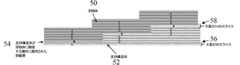
ファイル作成ソフトウエアの使用を示す概略図を、図5に示す。例えば、支持構造体52(灰色の点線の領域)は、物体50(青色の実線の領域)より下に仮想的に構築または生成される。ソフトウエアは、支持された物体50(すなわち、物体50および支持構造体52)を、1つの公称ポリマー層高さと等しい高さを有する層56へと仮想的に垂直にスライスするために使用され得る。物体50が支持構造体52と接触していることをソフトウエアが検出する場所で、ソフトウエアは、追加的な空間xを作成することができ、仮想空間58は、支持構造体52のポリマー層42と物体50のポリマー層42との間でx+1になる。空間はxと等しく、ソフトウエアによって作成されるスライスは1+xの高さを有することになる。三次元堆積プロセス中に、剥離剤または剥離層54が、xとして指定される空間に堆積されてもよく、ポリマー層42のフィラメント密度が、必要に応じて調節されてもよい。物体50が構築された時に物理的なギャップが存在しないように、フィラメント密度の調節が行われる。剥離剤は、支持構造体52の外側の層および物体50の外側の層に接触して、2つのポリマー層42を分離して2つのポリマー層42の接着を妨げる薄い剥離層54を形成してもよい。 A schematic diagram showing the use of the file creation software is shown in FIG. For example, the support structure 52 (gray dotted area) is virtually constructed or created below the object 50 (blue solid area). Software may be used to virtually vertically slice the supported object 50 (i.e., the
ある特定の態様において、剥離層54(本明細書において剥離剤層とも呼ぶ)は、物体50と支持構造体52との間に堆積される。剥離層54は、物体50、支持構造体52、または物体50と支持構造体52の両方の上に堆積されてもよい。ある特定の態様において、剥離層54は、支持構造体52上に堆積される。いくつかの態様において、剥離層54は、支持構造体52が物体50に取り付けられ、かつ/または物体50に隣接している位置にだけ堆積される。 In certain embodiments, a release layer 54 (also referred to herein as a release agent layer) is deposited between the
ある特定の態様において、支持構造体52を形成するポリマー層42は、剥離層54が支持構造体52のポリマー層42上に堆積される前に完全に堆積される。剥離層54が完全に堆積されると、物体50を形成するポリマー層42が、次いで、剥離層54上に堆積され得る。いくつかの態様において、ポリマー材料24が堆積されている最中に、剥離層54が、支持構造体52のポリマー層42上に印刷される。追加的な局面において、物体50のポリマー層42を形成するポリマー材料24が、支持構造体52のポリマー材料24および剥離層54が堆積されている間に、堆積される。他の態様において、ポリマー層42間に剥離層54を堆積させずに、支持構造体52を形成するポリマー層42が堆積され、物体50を形成するポリマー層42が堆積される。更に他の局面において、剥離層54は、堆積されたポリマー層(複数可)42を完全に覆って延在する必要はない。剥離層54は、前に堆積されたポリマー層42の一部分だけを覆って堆積されてもよい。 In certain embodiments, the
本発明によって利用される剥離剤は、ポリマー材料24(例えば、熱可塑性材料)の2つの連続する層間の接着を妨げてもよい。いくつかの局面において、剥離剤は、1つまたは複数の材料により製剤化されていてもよい。例えば、剥離剤は、シリコーン油、油および/または炭化水素、ポリエチレングリコール、エステル、界面活性剤、低粘着性接着剤、水溶性ゴム、可塑剤中もしくは揮発性溶媒中に溶解された固体剥離物質、ならびにこれらの組み合わせから選択される材料により製剤化されていてもよい。 The release agent utilized by the present invention may prevent the adhesion of two consecutive layers of polymeric material 24 (eg, thermoplastic material). In some aspects, exfoliants may be formulated with one or more materials. For example, release agents include silicone oils, oils and/or hydrocarbons, polyethylene glycols, esters, surfactants, low tack adhesives, water soluble rubbers, solid release materials dissolved in plasticizers or volatile solvents. , As well as materials selected from combinations thereof.
剥離剤は、非反応性化学作用、反応性化学作用、または相変化材料に基づいて選択され得る。相変化は、固体、液体、および/または気体の間を転移する材料を指す。例えば、相変化剥離剤は、液体から固体へ、または固体から液体へ転移してもよい。剥離剤材料は、ある特定の温度を上回るときに液体であってもよく、したがって液体状態で堆積される。この材料は、次いで、冷却時に固体化してもよい(例えば、ワックス材料)。反応性化学剥離剤は、2種以上のインク34の組み合わせを含んでもよく、個々のインク34が混合されるかおよび/または互いに接触するときに化学反応が発生する。個々のインク34は、それ自体は活性ではない。反応性化学剥離剤の一例は、二液性エポキシである。反応性化学剥離剤の別の例は、2種のインク34が接触するときに第2のインク34の重合が生じる触媒を一方のインク34が含有する、2種のインク34の組み合わせである。ある特定の局面において、反応性化学作用に基づいて選択される剥離剤を含むインク34は、1つまたは複数の印刷ヘッド33から堆積されるか、あるいは、複数のチャネルを有する単一の印刷ヘッド33から堆積される。 Release agents can be selected based on non-reactive chemistries, reactive chemistries, or phase change materials. Phase change refers to materials that transition between solids, liquids, and/or gases. For example, the phase change release agent may transition from liquid to solid or solid to liquid. The release agent material may be liquid above a certain temperature and is therefore deposited in the liquid state. This material may then solidify upon cooling (eg wax material). The reactive chemical stripping agent may include a combination of two or
いくつかの態様において、支持構造体52と物体50との間に形成される剥離層54はインク34を含み、インク34が剥離剤を含む。他の局面において、支持構造体52と物体50との間に形成される剥離層54はポリマー材料24を含み、ポリマー材料24は剥離剤を含む。いくつかの局面において、剥離剤は低粘着性接着剤である。低粘着性接着剤は、2つの表面(例えば、支持構造体52および物体50)の間に、低い接着力および取り外し可能な非永久的な接合を提供する。接着剤によって形成される結合材は、短い期間だけ維持されてもよく、いずれの表面にも任意の断裂または損傷を引き起こすことなく支持構造体52および/または物体50から取り外されかつ/または剥ぎ取られてもよい。接着剤の取り外しはまた、支持構造体52または物体50上に任意の粘着性または付着性残留物をもたらさない。 In some embodiments, the
ある特定の態様において、低粘着性接着剤は一時的糊剤(fugitive glue)またはE-Z剥離糊剤(例えば、手紙に取り付けられたダイレクトメールマーケティング製品またはクレジットカードの裏に見られるタイプの糊剤)である。一時的糊剤は、感圧、ホットメルト、水性の形で利用可能であってもよい。いくつかの態様において、ポストイット上に見られるような接着剤などの、低粘着性感圧性接着剤が利用される。このような接着剤は、表面上に残留物を残さずに容易に取り外され得る。 In certain embodiments, low tack adhesives are fugitive glues or EZ release glues (e.g., direct mail marketing products attached to letters or glues of the type found on the back of credit cards). Is. Temporary sizing agents may be available in pressure sensitive, hot melt, aqueous form. In some embodiments, low tack pressure sensitive adhesives are utilized, such as those found on Post-it. Such an adhesive can be easily removed without leaving a residue on the surface.
いくつかの態様において、低粘着性接着剤は、液状のインク34として1つまたは複数の印刷ヘッド33から吐出される。接着剤は、支持構造体52上へ液状で噴出されてもよく、これにより、支持構造体52に隣接して印刷された、支持構造体52と物体50との間の弱い結合材が形成される。いくつかの局面において、低粘着性システムは、押出機ヘッド(例えば、支持構造体52および/または物体50の製造用のポリマー材料24を吐出するために使用されるものとは異なる押出機ヘッド)からホットメルトとして吐出される。いくつかの局面において、物体50は、噴出された接着剤を含む支持構造体52の上部に(例えば、支持構造体52の上に載るように)製造される。支持構造体52上の物体50の製造によって、物体50が支持構造体52へ軽い圧力をかけるようにしてもよく、これにより、支持構造体52と物体50との間に一時性の結合が形成される。いくつかの局面において、物体50は、(例えば、低粘着性でかつ弱い接着性の結合の性質により)支持構造体52から取り外し可能である。 In some embodiments, the low tack adhesive is dispensed as
いくつかの態様において、支持構造体52と物体50との間に形成される剥離層54は、界面活性剤を含んだインク34を含む。「界面活性剤」は、本明細書において使用される場合、2つの液体、固体と液体、または2つの固体間の界面の表面特性を変化させることができる材料を指す。概して、界面活性剤の各分子は、親水性末端および親油性末端を含有する。いくつかの局面において、界面活性剤が(例えば、界面活性剤を含有するインク層40を堆積させることによって)ポリマー層42(例えば、ポリマー表面)上に堆積されるときに、親油性末端が非極性ポリマーの表面へ向かい親水性末端が極性ポリマーの表面へ向かうように界面活性剤分子は配向する。インクに利用されてもよい界面活性剤のタイプの非限定的な例としては、イオン性界面活性剤(例えば、カチオン性またはアニオン性界面活性剤)、非イオン性界面活性剤(例えば、オレイン酸ソルビタン乳化剤80、ポリソルベート80、ポリソルベート60)、または両性界面活性剤などが挙げられる。いくつかの態様において、支持構造体52と物体50との間に形成される剥離層54は、剥離層54が界面活性剤を含む場合、物体50からの支持構造体52の容易な取り外しを可能にする。 In some embodiments, the
取り外し可能な支持構造体52を伴う物体50を製造する初期工程中、ファイル作成ソフトウエアは、支持構造体と三次元物体との間に空間58(例えば、公称ポリマー高さ+空間x)を作成または仮想的に生成するために使用され得る。空間58は、シーンをスライスしている時に生成され得る。いくつかの態様において、支持構造体52と物体50との間の空間58は、ポリマー層42の厚さの0.1%〜100%である。いくつかの態様において、支持構造体52と物体50との間の空間58は、ポリマー層42の厚さの100%より大きい。いくつかの態様において、支持構造体52と物体50との間の空間58は、ポリマー層42の厚さの約5%、10%、20%、25%、30%、40%、50%、60%、70%、75%、80%、90%、または95%である。他の態様において、支持構造体52と物体50との間の空間58は、ポリマー層42の厚さの約50%である。いくつかの局面において、空間58は、物体50の曲率に基づいて調節される。支持構造体52と物体50との間の空間58を増加させることによって、支持構造体52の外側の層と物体50の第1の層との間(または、支持構造体52が物体50の上方に配置される場合には物体50の外側の層と支持構造体52の第1の層との間)の圧力が低減され得ることが概して理解される。対照的に、空間58が減少する場合、圧力が増加し得る。 During the initial process of manufacturing the
いくつかの局面において、剥離層54は、支持構造体52と物体50との間に堆積される。剥離層54は、支持構造体52上、物体50上、または支持構造体52と物体50の両方の上に堆積されてもよい。いくつかの局面において、空間58は、ファイル作成ソフトウエアを使用して支持構造体52の外側ポリマー層42と物体50との間に計算および/または形成される(例えば、公称ポリマー高さ+空間x)。いくつかの局面において、特定された空間58は、取り外し可能な支持構造体52を伴う物体50の製造中に、剥離層54によって一部または全体が充填される。 In some aspects, the
いくつかの態様において、ポリマー42および/または剥離層54の堆積速度は変動される。いくつかの局面において、堆積速度は、ポリマー層42の堆積から剥離層54の堆積へ移行するときに、あるいは剥離層54の堆積からポリマー層42の堆積へ移行するときに、低減または増加されてもよい。いくつかの局面において、堆積のより遅い速度は、小さな半径特徴、例えばサイズが10mm未満の特徴のために利用される。いくつかの局面において、タイミング遅延が、ポリマー層42および/または剥離層54の堆積の間で実施されてもよい。 In some embodiments, the deposition rate of
ある特定の態様において、支持構造体52および/または物体50のフィラメント密度は、製造中に調節または変動される。用語「フィラメント密度」は、標準層の自由体積に対する押し出された材料の体積の割合を指すために本明細書において使用される。標準層の自由体積は、標準層の(幅×長さ×高さ)として計算され得る(図5A参照)。いくつかの局面において、フィラメント密度の変動は、公称フィラメント密度の0.1〜2倍の範囲内である。他の局面において、フィラメント密度は、公称フィラメント密度の0.5〜1.7倍の範囲内である。ポリマー材料24のフィラメント密度の変動は、ポリマー材料24のタイプに依存してもよい。いくつかの態様において、剥離層54に隣接したポリマー層42のフィラメント密度が調節される。例えば、物体50の外側ポリマー層42が、支持構造体52上に堆積された剥離層54に隣接する場合には、物体50の外側ポリマー層42のフィラメント密度は、ポリマー層42の公称フィラメント密度の0.5〜1.7倍の範囲で変動され得る。あるいは、または加えて、支持構造体52の外側ポリマー層42が、物体50上に堆積された剥離層54に隣接する場合には、支持構造体52の外側ポリマー層42のフィラメント密度は、ポリマー層42の公称フィラメント密度の0.5〜1.7倍の範囲で変動され得る。いくつかの局面において、フィラメント密度は、物体50の曲率および/または支持構造体52の曲率に基づいて調節される。 In certain embodiments, the filament density of
いくつかの態様において、物体50および支持構造体52の製造は、ポリマー層42の堆積を含む。物体50および/または支持構造体52は、外側ポリマー層42を含んでもよい。いくつかの局面において、物体50の外側ポリマー層42は、強制冷却される。他の局面において、支持構造体52の外側ポリマー層42は、強制冷却される。あるいは、支持構造体52および/または物体50を形成する、複数のポリマー層42、またはいくつかの局面においてはすべてのポリマー層42が、強制冷却される。強制冷却は、ポリマー層42上に周囲空気もしくは外気を吹きつけることによって、またはポリマー層42に圧縮空気もしくは気体を適用することによって生じ得る。いくつかの局面において、剥離層54は、支持構造体52および物体50の外側ポリマー層42の間に堆積されてもよい。物体50の外側ポリマー層42および/または支持構造体52の外側ポリマー層42は、剥離層54の堆積の前に、強制冷却され得る。他の局面において、外側ポリマー層(複数可)42は、剥離層54の堆積の前、堆積中、または堆積の後に冷却される。いくつかの局面において、剥離層54は、高い熱伝導率を有するインクを含むか、または部分的にもしくは完全に蒸発する成分(例えば、冷却インク)を含有してもよく、これにより表面が冷却される。 In some embodiments, manufacturing the
本発明が、目的を実行して、言及された目標および利点ならびにそれに固有のものを得るために、うまく適合されることが当業者には容易に明白である。本明細書における記載および実施例の詳細は、ある特定の態様を表し、例示的であり、本発明の範囲に対する限定を意図しない。その中の修正および他の使用は、当業者に想起されるであろう。これらの修正は、本発明の趣旨に包含される。本発明の範囲および趣旨から逸脱することなく、本明細書において開示される本発明に対していろいろな置き換えおよび修正がなされ得ることが当業者には容易に明白であろう。 It will be readily apparent to those skilled in the art that the present invention is well adapted to carry out the objects and obtain the ends and advantages mentioned as well as those inherent therein. The details in the description and examples herein represent certain specific aspects, are exemplary, and are not intended as limitations on the scope of the invention. Modifications and other uses therein will occur to those skilled in the art. These modifications are included within the spirit of the invention. It will be readily apparent to those skilled in the art that various substitutions and modifications can be made to the invention disclosed herein without departing from the scope and spirit of the invention.
冠詞「a」および「an」は、明細書および特許請求の範囲で、本明細書において使用される場合、それとは反対に明らかに指示されない限り、複数の対象を含むと理解すべきである。群の1つまたは複数の要素間に「または、もしくは」を含む請求項または説明は、それとは反対に指示されない限りまたは別途文脈から明らかでない限り、群要素の1つ、2つ以上、またはすべてが、所与の製品またはプロセスに存在し、用いられ、または別途関連する場合に合致すると考えられる。本発明は、群のまさに1つの要素が所与の製品またはプロセスに存在し、用いられ、または別途関連する態様を含む。本発明はまた、群要素の2つ以上またはすべてが所与の製品またはプロセスに存在し、用いられ、または別途関連する態様を含む。更に、本発明は、列挙された請求項の1つまたは複数の、1つまたは複数の限定、構成要素、文節、記述用語などが、別途指示されない限りまたは矛盾もしくは不一致が生じることが当業者に明らかでない限り、同じ基本請求項に(または、関連する任意の他の請求項として)従属する別の請求項に導入されるすべての変更、組み合わせ、および入れ替えを提供することを理解すべきである。本明細書において記載されるすべての態様は、適切な場合には、本発明のすべての異なる局面に適用可能であることが企図される。態様または局面のうちのいずれかを、適当な場合にはいつでも、1つまたは複数の他のこのような態様または局面と自由に組み合わせることができることがまた企図される。構成要素が、一覧として、例えばマーカッシュ群または同様の形式で提示される場合、構成要素の各々のサブグループもまた開示され、任意の構成要素(複数可)が群から除去され得ることを理解すべきである。概して、本発明または本発明の局面が、特定の構成要素、特徴などを含むと称される場合、本発明のある特定の態様または本発明の局面は、このような構成要素、特徴などからなるまたは本質的になることを理解すべきである。単純化のために、これらの態様は、どの場合も、本明細書において多くの言葉で具体的には記載していない。具体的な除外が明細書において詳述されるかどうかにかかわらず、本発明の任意の態様または局面は明確に請求項から除外され得ることをまた理解すべきである。例えば、任意の1つもしくは複数の活性剤、添加物、成分、任意選択の剤、生物のタイプ、障害、対象、またはこれらの組み合わせが除外され得る。 The articles "a" and "an", as used in the specification and claims, should be understood to include the plural subjects unless explicitly stated to the contrary. A claim or description that includes "or" between one or more elements of a group, unless otherwise indicated or clear from the context otherwise, means one, more than one, or all of the group elements. Are present, used, or otherwise relevant to a given product or process and are considered to match. The invention includes embodiments in which exactly one member of the group is present in, employed in, or otherwise relevant to a given product or process. The invention also includes embodiments in which more than one or all of the group members are present in, employed in, or otherwise relevant to a given product or process. Furthermore, it is apparent to one of ordinary skill in the art that the present invention is subject to one or more of the recited claims, one or more of the limitations, components, clauses, descriptive terms, etc., unless otherwise indicated or a contradiction or inconsistency occurs. It is to be understood that it provides all modifications, combinations and permutations introduced in another claim that is dependent on the same basic claim (or as any other related claim), unless it is obvious. .. It is contemplated that all embodiments described herein are applicable to all different aspects of the invention where appropriate. It is also contemplated that any of the embodiments or aspects can be freely combined with one or more other such embodiments or aspects whenever appropriate. It is understood that when components are presented as a list, for example in Markush groups or similar formats, each subgroup of components is also disclosed, and any component(s) may be removed from the group. Should be. Generally, when an invention or aspect of the invention is referred to as comprising a particular component, feature, etc., a particular aspect of the invention or aspect of the invention comprises such component, feature, etc. Or it should be understood to become essential. For the sake of simplicity, these aspects are not specifically mentioned in many terms herein. It should also be understood that any embodiment or aspect of the invention may be explicitly excluded from the claims, regardless of whether the specific exclusions are detailed in the specification. For example, any one or more active agents, additives, ingredients, optional agents, organism types, disorders, subjects, or combinations thereof can be excluded.
請求項または記載が組成物に関する場合、本明細書に開示される方法のいずれかによって組成物を作製または使用する方法、および本明細書に開示される目的のいずれかのために組成物を使用する方法は、別途指示されない限りまたは矛盾もしくは不一致が生じることが当業者に明らかでない限り、本発明の局面であることを理解すべきである。請求項または記載が方法に関する場合、例えば、方法を実行するために有用な組成物を作製する方法、および方法に従って生産される製品は、別途指示されない限りまたは矛盾もしくは不一致が生じることが当業者に明らかでない限り、本発明の局面であることを理解すべきである。 Where the claim or description relates to a composition, a method of making or using the composition by any of the methods disclosed herein, and using the composition for any of the purposes disclosed herein. It is to be understood that the methods described herein are aspects of the invention unless otherwise indicated or apparent to one of ordinary skill in the art that inconsistencies or inconsistencies may occur. Where the claims or the description relate to a method, for example, to those skilled in the art, unless otherwise indicated or contradictory or inconsistent, the method of making a composition useful for performing the method and the product produced according to the method may occur. It should be understood that unless otherwise apparent, it is an aspect of the invention.
範囲が本明細書において与えられる場合、本発明は、終点が含まれる態様、両方の終点が除外される態様、および一方の終点が含まれ他方が除外される態様を含む。別途指示されない限り、両方の終点が含まれるとみなすべきである。更に、別途指示されない限り、または別途文脈および当業者の理解から明らかでない限り、範囲として表される値は、別途文脈が明らかに定めない限り範囲の下限の単位の10分の1まで、本発明のそれぞれの態様における記述された範囲内の任意の具体的な値または部分範囲とみなすことができることを理解すべきである。一連の数値が本明細書において記述される場合、本発明が任意のその間にある値または一連の数値の任意の2つの値によって定められる範囲に類似的に関連する態様を含み、最も低い値が最小とされてもよく、最も大きい値が最大とされてもよいこともまた理解される。数値は、本明細書において使用される場合、百分率として表される値を含む。数値が「約」または「およそ」によって前置される本発明の任意の態様では、本発明は、正確な値が詳述される態様を含む。数値が「約」または「およそ」によって前置されない本発明の任意の態様では、本発明は、値が「約」または「およそ」によって前置される態様を含む。 When ranges are given herein, the invention includes embodiments in which the endpoints are included, aspects in which both endpoints are excluded, and aspects in which one endpoint is included and the other is excluded. Both endpoints should be considered to be included unless otherwise indicated. Furthermore, unless otherwise indicated or clear from the understanding of the context and those of ordinary skill in the art, the values expressed as ranges are up to one tenth of the lower unit of the range, unless the context clearly dictates otherwise. It should be understood that any specific value or subrange within the stated range in each aspect of can be considered. When a series of numerical values is described herein, the invention is embodied in such a manner that the invention is similarly related to the range defined by any intervening value or any two values of the series, with the lowest value being the lowest value. It is also understood that there may be a minimum and the maximum value may be the maximum. Numerical values, as used herein, include values expressed as percentages. In any aspect of the invention in which a numerical value is preceded by “about” or “approximately”, the invention includes the aspect in which the exact value is detailed. In any aspect of the invention where a numerical value is not preceded by "about" or "approximately," the invention includes aspect in which the value is preceded by "about" or "approximately".
本明細書において使用される場合、「Aおよび/またはB」は、AおよびBが異なる請求項の用語である場合、概して、A、Bの少なくとも1つ、またはAおよびBの両方を意味する。例えば、別の配列に対して相補的でありおよび/または別の配列にハイブリダイズする1つの配列は、(i)1つの配列がすべての条件下で他の配列に必ずしもハイブリダイズしない場合があっても他の配列に対して相補的である1つの配列、(ii)1つの配列が他の配列に対して完全に相補的でなくても他の配列にハイブリダイズする1つの配列、および(iii)他の配列に対して相補的であり他の配列にハイブリダイズする配列を含む。 As used herein, "A and/or B" generally means at least one of A, B, or both A and B, where A and B are different claim terms. .. For example, one sequence that is complementary to and/or hybridizes to another sequence may (i) one sequence not necessarily hybridize to another under all conditions. Even one sequence that is complementary to the other sequence, (ii) one sequence that hybridizes to the other sequence even if the one sequence is not completely complementary to the other sequence, and ( iii) Includes sequences that are complementary to and hybridize to other sequences.
「およそ」または「約」は、概して、別途記述されない限りまたは別途文脈から明らかでない限り(このような数が、可能な値の100%を許容されないほど超える場合を除いて)、(数より大きいかまたは数より小さい)いずれかの方向で、1%の範囲内、またはいくつかの態様では数の5%の範囲内、またはいくつかの態様では数の10%の範囲内に該当する数を含む。それとは反対に明らかに指示されない限り、複数の行為を含む本明細書において特許請求される任意の方法において、方法の行為の順序は、方法の行為が列挙される順序に必ずしも限定されないが、本発明は、順序がそのように限定される態様を含むことを理解すべきである。別途指示されない限りまたは文脈から明らかでない限り、本明細書において記載される任意の製品または組成物は、「単離された」と考えられ得ることも理解すべきである。 “Approximately” or “about” generally means (unless such a number unacceptably exceeds 100% of the possible values) unless otherwise stated or clear from the context. In any direction) within 1%, or in some embodiments within 5% of the number, or in some embodiments within 10% of the number. Including. To the contrary, in any method claimed herein that includes a plurality of acts, unless explicitly stated otherwise, the order of the acts of the method is not necessarily limited to the order in which the acts of the method are listed. It is to be understood that the invention includes embodiments in which the order is so limited. It should also be understood that any product or composition described herein may be considered "isolated" unless otherwise indicated or clear from the context.
本明細書において使用される場合、用語「含む(comprising)」または「含む(comprises)」は、本発明に本質的である組成物、方法、およびこれらのそれぞれの構成部分(複数可)に関連して使用されるが、本質的であろうとなかろうと、特定されていない構成要素を含むことは自由である。 As used herein, the terms "comprising" or "comprises" relate to compositions, methods, and their respective component(s), which are essential to the invention. Used, but it is free to include unspecified components, whether essential or not.
本明細書において使用される場合、用語「から本質的になる」は、所与の態様のために必要とされるこれらの構成要素を指す。用語は、本発明のこの態様の基本的かつ新規なまたは機能的な特性(複数可)に物質的に影響を及ぼさない追加的な構成要素の存在を可能にする。 As used herein, the term "consisting essentially of" refers to those components required for a given embodiment. The term allows the presence of additional components that do not materially affect the basic and novel or functional property(s) of this aspect of the invention.
用語「からなる」は、態様のその説明において列挙されない任意の構成要素を除外した、本明細書において説明されるような組成物、方法、およびこれらのそれぞれの構成部分を指す。 The term “consisting of” refers to the compositions, methods, and their respective components, as excluding any component not listed in the description of the embodiment.
以下の非限定的な実施例は、本発明のインクの調製を示す。これらの実施例は、例示のみを目的とする。個々の配合それぞれの変更が可能であることは当業者には明白であろう。他のインク化学作用が、同様の剥離の便益を提供するために使用され得る。プラスチックフィラメントの性質に応じて、他の種類の材料、例えば、油および/または炭化水素、エステル、相変化インク、反応性インク、可塑剤中もしくは揮発性溶媒中に溶解された固体剥離物質を含有するインク、水溶性ゴム、剥離剤としての界面活性剤を含有するインク、ならびに一時的糊剤などの低粘着性システムが、剥離剤として使用され得るが、これらに限定されない。 The following non-limiting examples demonstrate the preparation of inks of the present invention. These examples are for illustrative purposes only. It will be apparent to those skilled in the art that variations in each individual formulation are possible. Other ink chemistries can be used to provide similar stripping benefits. Contains other types of materials, depending on the nature of the plastic filament, such as oils and/or hydrocarbons, esters, phase change inks, reactive inks, solid release materials dissolved in plasticizers or volatile solvents Inks, water-soluble rubbers, inks containing surfactants as release agents, and low tack systems such as temporary sizing agents can be used as release agents, but are not limited thereto.
すべての試験を、Rize, Inc.の社内で構築された三次元印刷機の試作品を使用して実行した。試作品は、専用の押出機ヘッドおよび1つまたは複数のRicoh Gen4圧電印刷ヘッドを備えていた。更に、専用のソフトウエアおよびファームウエアを、CADモデルをスライスしてプリンタを駆動するために使用した。 All tests were performed using an in-house built 3D press prototype of Rize, Inc. The prototype was equipped with a dedicated extruder head and one or more Ricoh Gen4 piezoelectric print heads. In addition, dedicated software and firmware were used to slice the CAD model and drive the printer.
実施例に列挙されるすべての百分率は、重量によって表されたものである。 All percentages listed in the examples are by weight.
実施例1-低粘度シリコーン油系インク
74%のDMS-T05ポリジメチルシロキサン(Gelest)、25%のDMS-T21ポリジメチルシロキサン(Gelest)、および1%の相溶性液体色素を含有するインクを調製した。色素は、印刷プロセスにおけるインクの視認性を提供するために加えたが、組成物に必要とされる成分ではない。すべての成分を共に加え、混合物を均質になるまで撹拌した。混合物を、次いで、1.0ミクロンガラス繊維フィルタで真空濾過した。得られたインクは、20℃で13cpsの粘度を有した。Example 1-Low viscosity silicone oil-based ink
An ink was prepared containing 74% DMS-T05 polydimethylsiloxane (Gelest), 25% DMS-T21 polydimethylsiloxane (Gelest), and 1% compatible liquid dye. The dye was added to provide visibility of the ink in the printing process, but is not a required ingredient in the composition. All ingredients were added together and the mixture was stirred until homogeneous. The mixture was then vacuum filtered with a 1.0 micron glass fiber filter. The resulting ink had a viscosity of 13 cps at 20°C.
TOPAS Advanced Polymers, Incから購入したTopas 7010F-600と共にRizeのアルファプリンタ試作品を使用して、インクを評価した。インクは、様々な幾何学的形状で良好な剥離特性を示した。 Inks were evaluated using Rize's alpha printer prototype with Topas 7010F-600 purchased from TOPAS Advanced Polymers, Inc. The inks showed good release properties with various geometries.
実施例2-高粘度シリコーン油系インク
57.5%のDMS-T05ポリジメチルシロキサン、40%のDMS-T21ポリジメチルシロキサン(Gelest)、2%のDMS-T31ポリジメチルシロキサン(Gelest)、および0.5%の相溶性液体色素を含有するインクを調製した。色素は、印刷プロセスにおけるインクの視認性を提供するために加えたが、組成物に必要とされる成分ではない。すべての成分を共に加え、混合物を均質になるまで撹拌した。混合物を、次いで、1.0ミクロンガラス繊維フィルタで濾過した。得られたインクは、22℃で24cpsの粘度を有した。Example 2-High-viscosity silicone oil-based ink
Prepared an ink containing 57.5% DMS-T05 polydimethylsiloxane, 40% DMS-T21 polydimethylsiloxane (Gelest), 2% DMS-T31 polydimethylsiloxane (Gelest), and 0.5% compatible liquid dye. did. The dye was added to provide visibility of the ink in the printing process, but is not a required ingredient in the composition. All ingredients were added together and the mixture was stirred until homogeneous. The mixture was then filtered on a 1.0 micron glass fiber filter. The resulting ink had a viscosity of 24 cps at 22°C.
印刷ヘッドの噴出パラメータを、良好で信頼性の高いインク噴出を提供するために調節した。TOPAS Advanced Polymers, Incから購入したTopas 7010F-600と共にRizeのアルファプリンタ試作品を使用して、インクを評価した。インクは、様々な幾何学的形状で良好な剥離特性を示した。 The printhead ejection parameters were adjusted to provide good and reliable ink ejection. Inks were evaluated using Rize's alpha printer prototype with Topas 7010F-600 purchased from TOPAS Advanced Polymers, Inc. The inks showed good release properties with various geometries.
実施例3-ポリエチレングリコール系インク
60%のポリエチレングリコール400(Sigma)、38%のジプロピレングリコールメチルエーテル(Spectrum Chemicals)、1%のBYK333界面活性剤(BYK Chemie)、および1%の相溶性液体色素を含有するインクを調製した。色素は、印刷プロセスにおけるインクの視認性を提供するために加えたが、組成物に必要とされる成分ではない。ポリエチレングリコール400、ジプロピレングリコールメチルエーテル、および界面活性剤を、最初に共に加え、均質な溶液を形成するまで撹拌した。次いで色素を加え、混合物を均質になるまで撹拌した。次いで、混合物を1.0ミクロンガラス繊維フィルタで濾過した。得られたインクは、22℃で26cpsの粘度を有した。Example 3-Polyethylene glycol ink
An ink was prepared containing 60% polyethylene glycol 400 (Sigma), 38% dipropylene glycol methyl ether (Spectrum Chemicals), 1% BYK333 surfactant (BYK Chemie), and 1% compatible liquid dye. .. The dye was added to provide visibility of the ink in the printing process, but is not a required ingredient in the composition. Polyethylene glycol 400, dipropylene glycol methyl ether, and surfactant were first added together and stirred until a homogeneous solution was formed. The dye was then added and the mixture was stirred until homogeneous. The mixture was then filtered through a 1.0 micron glass fiber filter. The resulting ink had a viscosity of 26 cps at 22°C.
TOPAS Advanced Polymers, Incから購入したTopas 7010F-600と共にRizeのアルファプリンタ試作品を使用して、インクを評価した。インクは、様々な幾何学的形状で良好な剥離特性を示した。 Inks were evaluated using Rize's alpha printer prototype with Topas 7010F-600 purchased from TOPAS Advanced Polymers, Inc. The inks showed good release properties with various geometries.
実施例4-界面活性剤インクの評価
39.5%のDowanol PPh、39.5%のDowanol TMP、20.7%のSpan 80、および0.3%の相溶性色素を含有するインクを調製した。色素は、印刷プロセスにおけるインクの視認性を提供するために加えたが、組成物に必要とされる成分ではない。成分のすべてを共に加え、混合物を均質になるまで撹拌した。次いで、混合物を1.0ミクロンガラス繊維フィルタで真空濾過した。得られたインクは、20℃で17cpsの粘度を有した。Example 4-Evaluation of surfactant ink
An ink was prepared containing 39.5% Dowanol PPh, 39.5% Dowanol TMP, 20.7% Span 80, and 0.3% compatible dye. The dye was added to provide visibility of the ink in the printing process, but is not a required ingredient in the composition. All of the ingredients were added together and the mixture was stirred until homogeneous. The mixture was then vacuum filtered with a 1.0 micron glass fiber filter. The resulting ink had a viscosity of 17 cps at 20°C.
TOPAS Advanced Polymers, Incから購入したTopas 7010F-600から生産されるフィラメントを用いて、Rizeのプリンタ試作品でインクを評価した。冷却効果、および印刷プロセス中の層の高さの調節を評価するために、複数の試験を実行した。 Inks were evaluated in a Rize printer prototype using filaments produced from Topas 7010F-600 purchased from TOPAS Advanced Polymers, Inc. Multiple tests were carried out to evaluate the cooling effect and the adjustment of the layer height during the printing process.
第1に、3段の階段構造体を、1画素当たり2液滴のインク飽和状態および90mm/秒の押出機速度を使用して印刷した。一部の剥離が1段目上で達成されたが、2段目および3段目上では剥離は達成されなかった。 First, a three-step staircase structure was printed using 2 drops of ink saturation per pixel and an extruder speed of 90 mm/sec. Some peeling was achieved on the first tier, but not on the second and third tiers.
第2に、第1の実験を繰り返したが、層の高さを、支持体と剥離層との間の境界領域において50%増加させた。3段すべてが、いくらかの労力で剥離されたが、剥離層の上方の層の表面が完全ではなかった。 Second, the first experiment was repeated, but the layer height was increased by 50% in the boundary area between the support and the release layer. All three layers were stripped with some effort, but the surface of the layer above the release layer was not perfect.
第3に、第2の実験を繰り返したが、剥離インク層を堆積させる工程と剥離の上方に層を押し出す工程との間に10秒の遅延時間を設けた。これにより、容易な剥離がもたらされ、良好な表面が提供された。 Third, the second experiment was repeated, but with a 10 second delay between depositing the release ink layer and pushing the layer above the release. This provided easy release and provided a good surface.
第4に、第2の実験を再び繰り返したが、印刷中に、押し出された層を冷却するために送風機を使用した。層間に遅延は生じなかった。良好な剥離および良好な表面が結果としてもたらされた。 Fourth, the second experiment was repeated again but using a blower to cool the extruded layer during printing. There was no delay between the layers. Good release and good surface resulted.
第5に、第4の実験を繰り返したが、剥離インクを支持体表面上に印刷しなかった。剥離は、いかなる層上でも実証されなかった。 Fifth, the fourth experiment was repeated but the release ink was not printed on the support surface. Delamination was not demonstrated on any of the layers.
第6に、第4の実験を、様々な複雑なパーツを印刷するために繰り返した。すべてのパーツにおいて、支持体の上方のパーツの領域上で容易な剥離および良好な表面が示された。 Sixth, the fourth experiment was repeated to print various complex parts. All parts showed easy release and good surface on the area of the part above the support.
最後に、剥離層の上方および下方でフィラメント密度を変動させて、多数の実験を行った。剥離層の上方および下方の低いフィラメント密度は、層間の距離の追加的な変化と類似した効果を提供した。 Finally, a number of experiments were performed with varying filament density above and below the release layer. The low filament densities above and below the release layer provided effects similar to additional changes in the distance between the layers.
Claims (25)
Translated fromJapanese(b)プロセッサを使用して、該三次元物体のための支持構造体を仮想的に生成する工程;
(c)プロセッサを使用して、該支持構造体および該三次元物体を含むシーンを層へ仮想的にスライスする工程;
(d)プロセッサを使用して、該支持構造体が該三次元物体に隣接している各層の領域を特定する工程;
(e)支持構造体および/または三次元物体のポリマー層を堆積させる印刷装置;
(f)剥離剤を含む層を該支持構造体および/または該三次元物体の該ポリマー層の少なくとも一部分の上に堆積させる印刷装置;ならびに
(g)該三次元物体および/または該支持構造体の少なくとも1つのポリマー層を、該剥離剤を含む該層の上に堆積させる印刷装置
を含む三次元製造方法。(a) identifying a region of a three-dimensional object that requires a support structure using a processor;
(b) using a processor to virtually generate a support structure for the three-dimensional object;
(c) virtually slicing a scene containing the support structure and the three-dimensional object into layers using a processor;
(d) using a processor to identify the area of each layer where the support structure is adjacent to the three-dimensional object;
(e) a printing device for depositing a support structure and/or a polymer layer of a three-dimensional object;
(f) a printing device in which a layer containing a release agent is deposited on at least a portion of the polymeric layer of the support structure and/or the three-dimensional object; and
(g) A three-dimensional manufacturing method including a printing device in which at least one polymer layer of the three-dimensional object and/or the support structure is deposited on the layer containing the release agent.
(b)該三次元物体の形成中に、三次元プリンタの使用により、該三次元物体に隣接する支持構造体を形成する工程
を含み、
剥離剤を含む層が、該三次元物体と該支持構造体との間に堆積される、
三次元製造方法。(a) forming a three-dimensional object by using a three-dimensional printer; and
(b) forming a support structure adjacent to the three-dimensional object by using a three-dimensional printer during formation of the three-dimensional object,
A layer containing a release agent is deposited between the three-dimensional object and the support structure,
Three-dimensional manufacturing method.
(b)該三次元物体の形成中に、三次元プリンタの使用により、該三次元物体に隣接する支持構造体を形成する工程
を含み、
該支持構造体および/または該三次元物体の少なくとも1つの外側ポリマー層に強制冷却が適用される、
三次元製造方法。(a) forming a three-dimensional object by using a three-dimensional printer; and
(b) forming a support structure adjacent to the three-dimensional object by using a three-dimensional printer during formation of the three-dimensional object,
Forced cooling is applied to at least one outer polymer layer of the support structure and/or the three-dimensional object,
Three-dimensional manufacturing method.
(b)該三次元物体の形成中に、三次元プリンタの使用により、該三次元物体に隣接する支持構造体を形成する工程
を含み、
剥離剤を含む層が、該三次元物体と該支持構造体との間に堆積され、該剥離剤が、2つの連続するポリマー層間の接着を妨げる、
三次元製造方法。(a) forming a three-dimensional object by using a three-dimensional printer; and
(b) forming a support structure adjacent to the three-dimensional object by using a three-dimensional printer during formation of the three-dimensional object,
A layer containing a release agent is deposited between the three-dimensional object and the support structure, the release agent preventing adhesion between two consecutive polymer layers.
Three-dimensional manufacturing method.
(b)外側ポリマー層を有する三次元印刷された支持構造体と、
(c)該三次元物体の該外側ポリマー層と該支持構造体の該外側ポリマー層との間に堆積された、剥離剤を含む層と
を含む製品。(a) a three-dimensionally printed object having an outer polymer layer,
(b) a three-dimensionally printed support structure having an outer polymer layer,
(c) An article comprising a layer comprising a release agent deposited between the outer polymer layer of the three-dimensional object and the outer polymer layer of the support structure.
Applications Claiming Priority (2)
| Application Number | Priority Date | Filing Date | Title |
|---|---|---|---|
| US201662381300P | 2016-08-30 | 2016-08-30 | |
| US62/381,300 | 2016-08-30 |
Related Parent Applications (1)
| Application Number | Title | Priority Date | Filing Date |
|---|---|---|---|
| JP2019521803ADivisionJP6703192B2 (en) | 2016-08-30 | 2017-07-14 | Method for manufacturing a three-dimensional object with a removable support structure |
Publications (2)
| Publication Number | Publication Date |
|---|---|
| JP2020121571Atrue JP2020121571A (en) | 2020-08-13 |
| JP2020121571A5 JP2020121571A5 (en) | 2020-11-19 |
Family
ID=61309464
Family Applications (2)
| Application Number | Title | Priority Date | Filing Date |
|---|---|---|---|
| JP2019521803AExpired - Fee RelatedJP6703192B2 (en) | 2016-08-30 | 2017-07-14 | Method for manufacturing a three-dimensional object with a removable support structure |
| JP2020081822APendingJP2020121571A (en) | 2016-08-30 | 2020-05-07 | Method of fabricating three-dimensional object with removable support structure |
Family Applications Before (1)
| Application Number | Title | Priority Date | Filing Date |
|---|---|---|---|
| JP2019521803AExpired - Fee RelatedJP6703192B2 (en) | 2016-08-30 | 2017-07-14 | Method for manufacturing a three-dimensional object with a removable support structure |
Country Status (6)
| Country | Link |
|---|---|
| US (1) | US20190193335A1 (en) |
| EP (1) | EP3507093A4 (en) |
| JP (2) | JP6703192B2 (en) |
| KR (2) | KR20200016410A (en) |
| CN (1) | CN109982848A (en) |
| WO (1) | WO2018044399A1 (en) |
Families Citing this family (22)
| Publication number | Priority date | Publication date | Assignee | Title |
|---|---|---|---|---|
| MX2020007791A (en) | 2018-01-23 | 2020-11-11 | Local Motors Ip Llc | Additively manufactured structure and method for making the same. |
| WO2019150256A1 (en)* | 2018-02-05 | 2019-08-08 | 3M Innovative Properties Company | Radiation-curable composition containing mercapto-functional polyorganosiloxanes for additive-manufacturing technology |
| JP7023145B2 (en)* | 2018-03-12 | 2022-02-21 | エス.ラボ株式会社 | Modeling equipment and modeling method |
| US11453172B2 (en) | 2018-06-22 | 2022-09-27 | 3D Systems, Inc. | 3D printing build materials and support materials comprising a phosphor |
| US11104079B2 (en) | 2018-06-22 | 2021-08-31 | 3D Systems, Inc. | Three-dimensional article having permanent phosphor indicia formed from sacrificial support material |
| EP3810401B1 (en) | 2018-06-22 | 2022-08-03 | 3D Systems, Inc. | Method of verifying integrity of a post-process removal of support material |
| JP7159777B2 (en)* | 2018-10-15 | 2022-10-25 | セイコーエプソン株式会社 | Manufacturing method of three-dimensional model |
| DE102019002936A1 (en)* | 2019-04-23 | 2020-10-29 | Universität Stuttgart | Water-soluble support structures for the strand-laying process |
| WO2020250229A1 (en)* | 2019-06-13 | 2020-12-17 | Stratasys Ltd. | System and method for 3d printing a support structure |
| CN111168064B (en)* | 2019-12-02 | 2022-04-05 | 西安铂力特增材技术股份有限公司 | A method for automatic repair of supports based on additive manufacturing |
| DE102020104296A1 (en)* | 2020-02-19 | 2021-08-19 | Grob-Werke Gmbh & Co. Kg | METHOD AND DEVICE FOR ADDITIVE MANUFACTURING OF A COMPONENT |
| CN111497221B (en)* | 2020-05-15 | 2022-04-01 | 浙江迅实科技有限公司 | Remove 3D printer that prints support fast |
| CN111497222B (en)* | 2020-05-15 | 2022-03-11 | 浙江迅实科技有限公司 | 3D printing method for quickly removing printing support |
| KR102305843B1 (en)* | 2020-05-18 | 2021-09-28 | (주)메타몰프 | Method and apparatus for generating slice data of 3d printer |
| US20220063187A1 (en)* | 2020-08-27 | 2022-03-03 | Xerox Corporation | Polymer filaments comprising a gas-forming compound and additive manufacturing therewith |
| EP4116063A1 (en)* | 2021-07-07 | 2023-01-11 | ACMIT Gmbh | Method for the additive manufacturing of a shaped body |
| CN114042935A (en)* | 2021-10-28 | 2022-02-15 | 西安交通大学 | A kind of water-washing support material and forming method for metal additive manufacturing |
| US11890677B2 (en) | 2021-12-23 | 2024-02-06 | Xerox Corporation | Fracturable support structure and method of forming the structure |
| US20240009935A1 (en)* | 2022-07-07 | 2024-01-11 | Xerox Corporation | Fracturable support structure and method of forming the structure |
| US20240009934A1 (en)* | 2022-07-07 | 2024-01-11 | Xerox Corporation | Fracturable support structure and method of forming the structure |
| DE102022121548A1 (en)* | 2022-08-25 | 2024-03-07 | Tesa Se | Method for printing three-dimensional structures with reduced processing effort |
| US20250100222A1 (en)* | 2023-09-21 | 2025-03-27 | Xerox Corporation | Preceramic interfacial and support structures for inorganic material printing and methods thereof |
Citations (3)
| Publication number | Priority date | Publication date | Assignee | Title |
|---|---|---|---|---|
| JPH0924552A (en)* | 1994-06-02 | 1997-01-28 | Stratasys Inc | 3D object manufacturing method |
| US20120080814A1 (en)* | 2010-09-28 | 2012-04-05 | Drexel University | Integratable Assisted Cooling System for Precision Extrusion Deposition in the Fabrication of 3D Scaffolds |
| JP2015007128A (en)* | 2007-06-15 | 2015-01-15 | リサーチ トライアングル インスティテュート | Androstane and pregnane steroids with potential allosteric gaba receptor chloride ionophore-modulating properties |
Family Cites Families (11)
| Publication number | Priority date | Publication date | Assignee | Title |
|---|---|---|---|---|
| EP0655317A1 (en)* | 1993-11-03 | 1995-05-31 | Stratasys Inc. | Rapid prototyping method for separating a part from a support structure |
| US7314591B2 (en)* | 2001-05-11 | 2008-01-01 | Stratasys, Inc. | Method for three-dimensional modeling |
| US6165406A (en)* | 1999-05-27 | 2000-12-26 | Nanotek Instruments, Inc. | 3-D color model making apparatus and process |
| US7300619B2 (en)* | 2000-03-13 | 2007-11-27 | Objet Geometries Ltd. | Compositions and methods for use in three dimensional model printing |
| EP2632696B1 (en)* | 2010-10-27 | 2020-07-29 | Rize Inc. | Process and apparatus for fabrication of three-dimensional objects |
| JP2016501136A (en)* | 2012-11-09 | 2016-01-18 | エボニック インダストリーズ アクチエンゲゼルシャフトEvonik Industries AG | Multicolor extrusion 3D printing |
| ES2744404T3 (en)* | 2013-03-14 | 2020-02-25 | Stratasys Ltd | Laminated and / or textured for three-dimensional printing |
| WO2014199231A2 (en)* | 2013-05-24 | 2014-12-18 | Looking Glass Hk Ltd. | Method for manufacturing a physical volumetric representation of a virtual three-dimensional object |
| EP3057776B1 (en)* | 2013-10-17 | 2020-03-18 | Xjet Ltd. | Support ink for three dimensional (3d) printing |
| JP6294659B2 (en)* | 2013-12-26 | 2018-03-14 | 株式会社ミマキエンジニアリング | Manufacturing method and control device of shaped object |
| US11001049B2 (en)* | 2015-01-12 | 2021-05-11 | Avient Corporation | Support material for 3D printing of polymer compounds |
- 2017
- 2017-07-14CNCN201780067430.7Apatent/CN109982848A/enactivePending
- 2017-07-14KRKR1020207003660Apatent/KR20200016410A/ennot_activeCeased
- 2017-07-14EPEP17847127.2Apatent/EP3507093A4/ennot_activeWithdrawn
- 2017-07-14USUS16/329,711patent/US20190193335A1/ennot_activeAbandoned
- 2017-07-14KRKR1020197008696Apatent/KR102077206B1/ennot_activeExpired - Fee Related
- 2017-07-14WOPCT/US2017/042223patent/WO2018044399A1/ennot_activeCeased
- 2017-07-14JPJP2019521803Apatent/JP6703192B2/ennot_activeExpired - Fee Related
- 2020
- 2020-05-07JPJP2020081822Apatent/JP2020121571A/enactivePending
Patent Citations (3)
| Publication number | Priority date | Publication date | Assignee | Title |
|---|---|---|---|---|
| JPH0924552A (en)* | 1994-06-02 | 1997-01-28 | Stratasys Inc | 3D object manufacturing method |
| JP2015007128A (en)* | 2007-06-15 | 2015-01-15 | リサーチ トライアングル インスティテュート | Androstane and pregnane steroids with potential allosteric gaba receptor chloride ionophore-modulating properties |
| US20120080814A1 (en)* | 2010-09-28 | 2012-04-05 | Drexel University | Integratable Assisted Cooling System for Precision Extrusion Deposition in the Fabrication of 3D Scaffolds |
Also Published As
| Publication number | Publication date |
|---|---|
| CN109982848A (en) | 2019-07-05 |
| EP3507093A1 (en) | 2019-07-10 |
| KR102077206B1 (en) | 2020-02-14 |
| KR20190039440A (en) | 2019-04-11 |
| WO2018044399A1 (en) | 2018-03-08 |
| JP6703192B2 (en) | 2020-06-03 |
| US20190193335A1 (en) | 2019-06-27 |
| JP2019528203A (en) | 2019-10-10 |
| EP3507093A4 (en) | 2020-04-08 |
| KR20200016410A (en) | 2020-02-14 |
Similar Documents
| Publication | Publication Date | Title |
|---|---|---|
| JP6703192B2 (en) | Method for manufacturing a three-dimensional object with a removable support structure | |
| US11135777B2 (en) | Poylmeric composition for use as a temporary support material in extrusion based additive manufacturing | |
| US11097472B2 (en) | Generating three-dimensional objects | |
| TWI583538B (en) | Technique for generating three-dimensional objects | |
| US10286601B2 (en) | Color or multi-material three-dimensional (3D) printing | |
| JP5431576B2 (en) | Compositions and methods for selective deposition modeling | |
| JP6444077B2 (en) | Three-dimensional structure forming apparatus and forming method | |
| JP6292857B2 (en) | Manufacturing method of structure | |
| CN105026132B (en) | For being layered the viscosity and bonding adhesive system and method for object manufacture | |
| CN105916663A (en) | Generating a three-dimensional object | |
| US20150151487A1 (en) | 3d printing techniques for creating tissue engineering scaffolds | |
| CN103189186A (en) | Three-dimensional shaping device and three-dimensional shaping method | |
| JP2014024329A (en) | Method and apparatus for manufacturing structure | |
| JP6686302B2 (en) | Active energy ray curable composition, active energy ray curable ink, composition container, image forming apparatus, image forming method, cured product, molded product | |
| JP2018098506A5 (en) | ||
| JP2019018526A (en) | Three-dimensional structure forming apparatus and three-dimensional structure forming method | |
| JP2020059227A (en) | Manufacturing method and apparatus for three-dimensional modeling object | |
| CN106346772A (en) | Three-dimensional full-color composite printing device | |
| CN106363907A (en) | Three-dimensional full-color composite printing device | |
| JP6944849B2 (en) | Manufacturing method of three-dimensional model and support material composition for three-dimensional model | |
| JP6730412B2 (en) | 3D object generation | |
| KR20210066167A (en) | Apparatus for manufacturing functional parts using 3D printing and method therefor | |
| KR20190143517A (en) | 3-dimension based printing method and printing apparatus using capacitive droplet ejection type |
Legal Events
| Date | Code | Title | Description |
|---|---|---|---|
| A521 | Request for written amendment filed | Free format text:JAPANESE INTERMEDIATE CODE: A523 Effective date:20200714 | |
| A621 | Written request for application examination | Free format text:JAPANESE INTERMEDIATE CODE: A621 Effective date:20200714 | |
| A521 | Request for written amendment filed | Free format text:JAPANESE INTERMEDIATE CODE: A523 Effective date:20200729 | |
| RD04 | Notification of resignation of power of attorney | Free format text:JAPANESE INTERMEDIATE CODE: A7424 Effective date:20210119 | |
| A977 | Report on retrieval | Free format text:JAPANESE INTERMEDIATE CODE: A971007 Effective date:20210709 | |
| A131 | Notification of reasons for refusal | Free format text:JAPANESE INTERMEDIATE CODE: A131 Effective date:20210714 | |
| A02 | Decision of refusal | Free format text:JAPANESE INTERMEDIATE CODE: A02 Effective date:20220221 |