JP2020117070A - Mobile controller - Google Patents
Mobile controllerDownload PDFInfo
- Publication number
- JP2020117070A JP2020117070AJP2019009738AJP2019009738AJP2020117070AJP 2020117070 AJP2020117070 AJP 2020117070AJP 2019009738 AJP2019009738 AJP 2019009738AJP 2019009738 AJP2019009738 AJP 2019009738AJP 2020117070 AJP2020117070 AJP 2020117070A
- Authority
- JP
- Japan
- Prior art keywords
- heater
- state
- outside air
- vehicle
- air
- Prior art date
- Legal status (The legal status is an assumption and is not a legal conclusion. Google has not performed a legal analysis and makes no representation as to the accuracy of the status listed.)
- Pending
Links
Images


Classifications
- B—PERFORMING OPERATIONS; TRANSPORTING
- B60—VEHICLES IN GENERAL
- B60H—ARRANGEMENTS OF HEATING, COOLING, VENTILATING OR OTHER AIR-TREATING DEVICES SPECIALLY ADAPTED FOR PASSENGER OR GOODS SPACES OF VEHICLES
- B60H1/00—Heating, cooling or ventilating [HVAC] devices
- B60H1/00642—Control systems or circuits; Control members or indication devices for heating, cooling or ventilating devices
- B60H1/00735—Control systems or circuits characterised by their input, i.e. by the detection, measurement or calculation of particular conditions, e.g. signal treatment, dynamic models
- B60H1/00785—Control systems or circuits characterised by their input, i.e. by the detection, measurement or calculation of particular conditions, e.g. signal treatment, dynamic models by the detection of humidity or frost
- B—PERFORMING OPERATIONS; TRANSPORTING
- B60—VEHICLES IN GENERAL
- B60H—ARRANGEMENTS OF HEATING, COOLING, VENTILATING OR OTHER AIR-TREATING DEVICES SPECIALLY ADAPTED FOR PASSENGER OR GOODS SPACES OF VEHICLES
- B60H1/00—Heating, cooling or ventilating [HVAC] devices
- B60H1/00642—Control systems or circuits; Control members or indication devices for heating, cooling or ventilating devices
- B60H1/00814—Control systems or circuits characterised by their output, for controlling particular components of the heating, cooling or ventilating installation
- B60H1/00821—Control systems or circuits characterised by their output, for controlling particular components of the heating, cooling or ventilating installation the components being ventilating, air admitting or air distributing devices
- B60H1/00835—Damper doors, e.g. position control
- B60H1/00849—Damper doors, e.g. position control for selectively commanding the induction of outside or inside air
- B—PERFORMING OPERATIONS; TRANSPORTING
- B60—VEHICLES IN GENERAL
- B60H—ARRANGEMENTS OF HEATING, COOLING, VENTILATING OR OTHER AIR-TREATING DEVICES SPECIALLY ADAPTED FOR PASSENGER OR GOODS SPACES OF VEHICLES
- B60H1/00—Heating, cooling or ventilating [HVAC] devices
- B60H1/00642—Control systems or circuits; Control members or indication devices for heating, cooling or ventilating devices
- B60H1/00814—Control systems or circuits characterised by their output, for controlling particular components of the heating, cooling or ventilating installation
- B60H1/00878—Control systems or circuits characterised by their output, for controlling particular components of the heating, cooling or ventilating installation the components being temperature regulating devices
- B—PERFORMING OPERATIONS; TRANSPORTING
- B60—VEHICLES IN GENERAL
- B60H—ARRANGEMENTS OF HEATING, COOLING, VENTILATING OR OTHER AIR-TREATING DEVICES SPECIALLY ADAPTED FOR PASSENGER OR GOODS SPACES OF VEHICLES
- B60H1/00—Heating, cooling or ventilating [HVAC] devices
- B60H1/22—Heating, cooling or ventilating [HVAC] devices the heat being derived otherwise than from the propulsion plant
- B60H1/2215—Heating, cooling or ventilating [HVAC] devices the heat being derived otherwise than from the propulsion plant the heat being derived from electric heaters
- B60H1/2218—Heating, cooling or ventilating [HVAC] devices the heat being derived otherwise than from the propulsion plant the heat being derived from electric heaters controlling the operation of electric heaters
- B—PERFORMING OPERATIONS; TRANSPORTING
- B60—VEHICLES IN GENERAL
- B60H—ARRANGEMENTS OF HEATING, COOLING, VENTILATING OR OTHER AIR-TREATING DEVICES SPECIALLY ADAPTED FOR PASSENGER OR GOODS SPACES OF VEHICLES
- B60H1/00—Heating, cooling or ventilating [HVAC] devices
- B60H1/22—Heating, cooling or ventilating [HVAC] devices the heat being derived otherwise than from the propulsion plant
- B60H1/2215—Heating, cooling or ventilating [HVAC] devices the heat being derived otherwise than from the propulsion plant the heat being derived from electric heaters
- B60H1/2227—Electric heaters incorporated in vehicle trim components, e.g. panels or linings
- B—PERFORMING OPERATIONS; TRANSPORTING
- B60—VEHICLES IN GENERAL
- B60R—VEHICLES, VEHICLE FITTINGS, OR VEHICLE PARTS, NOT OTHERWISE PROVIDED FOR
- B60R1/00—Optical viewing arrangements; Real-time viewing arrangements for drivers or passengers using optical image capturing systems, e.g. cameras or video systems specially adapted for use in or on vehicles
- B60R1/001—Optical viewing arrangements; Real-time viewing arrangements for drivers or passengers using optical image capturing systems, e.g. cameras or video systems specially adapted for use in or on vehicles integrated in the windows, e.g. Fresnel lenses
- B—PERFORMING OPERATIONS; TRANSPORTING
- B60—VEHICLES IN GENERAL
- B60S—SERVICING, CLEANING, REPAIRING, SUPPORTING, LIFTING, OR MANOEUVRING OF VEHICLES, NOT OTHERWISE PROVIDED FOR
- B60S1/00—Cleaning of vehicles
- B60S1/02—Cleaning windscreens, windows or optical devices
- B60S1/023—Cleaning windscreens, windows or optical devices including defroster or demisting means
- B60S1/026—Cleaning windscreens, windows or optical devices including defroster or demisting means using electrical means
- B—PERFORMING OPERATIONS; TRANSPORTING
- B60—VEHICLES IN GENERAL
- B60S—SERVICING, CLEANING, REPAIRING, SUPPORTING, LIFTING, OR MANOEUVRING OF VEHICLES, NOT OTHERWISE PROVIDED FOR
- B60S1/00—Cleaning of vehicles
- B60S1/02—Cleaning windscreens, windows or optical devices
- B60S1/04—Wipers or the like, e.g. scrapers
- B60S1/06—Wipers or the like, e.g. scrapers characterised by the drive
- B60S1/08—Wipers or the like, e.g. scrapers characterised by the drive electrically driven
- B60S1/0818—Wipers or the like, e.g. scrapers characterised by the drive electrically driven including control systems responsive to external conditions, e.g. by detection of moisture, dirt or the like
- B60S1/0822—Wipers or the like, e.g. scrapers characterised by the drive electrically driven including control systems responsive to external conditions, e.g. by detection of moisture, dirt or the like characterized by the arrangement or type of detection means
- B60S1/0833—Optical rain sensor
- B60S1/0844—Optical rain sensor including a camera
- B60S1/0848—Cleaning devices for cameras on vehicle
- B—PERFORMING OPERATIONS; TRANSPORTING
- B60—VEHICLES IN GENERAL
- B60S—SERVICING, CLEANING, REPAIRING, SUPPORTING, LIFTING, OR MANOEUVRING OF VEHICLES, NOT OTHERWISE PROVIDED FOR
- B60S1/00—Cleaning of vehicles
- B60S1/02—Cleaning windscreens, windows or optical devices
- B60S1/54—Cleaning windscreens, windows or optical devices using gas, e.g. hot air
- B60S1/544—Cleaning windscreens, windows or optical devices using gas, e.g. hot air moving gas spreading means, e.g. arranged in wiper arms
- B—PERFORMING OPERATIONS; TRANSPORTING
- B60—VEHICLES IN GENERAL
- B60H—ARRANGEMENTS OF HEATING, COOLING, VENTILATING OR OTHER AIR-TREATING DEVICES SPECIALLY ADAPTED FOR PASSENGER OR GOODS SPACES OF VEHICLES
- B60H1/00—Heating, cooling or ventilating [HVAC] devices
- B60H1/24—Devices purely for ventilating or where the heating or cooling is irrelevant
- B60H1/26—Ventilating openings in vehicle exterior; Ducts for conveying ventilating air
- B—PERFORMING OPERATIONS; TRANSPORTING
- B60—VEHICLES IN GENERAL
- B60H—ARRANGEMENTS OF HEATING, COOLING, VENTILATING OR OTHER AIR-TREATING DEVICES SPECIALLY ADAPTED FOR PASSENGER OR GOODS SPACES OF VEHICLES
- B60H1/00—Heating, cooling or ventilating [HVAC] devices
- B60H1/00642—Control systems or circuits; Control members or indication devices for heating, cooling or ventilating devices
- B60H1/0073—Control systems or circuits characterised by particular algorithms or computational models, e.g. fuzzy logic or dynamic models
- B60H2001/00733—Computational models modifying user-set values
Landscapes
- Engineering & Computer Science (AREA)
- Mechanical Engineering (AREA)
- Physics & Mathematics (AREA)
- Thermal Sciences (AREA)
- Multimedia (AREA)
- Automation & Control Theory (AREA)
- Air-Conditioning For Vehicles (AREA)
- Fittings On The Vehicle Exterior For Carrying Loads, And Devices For Holding Or Mounting Articles (AREA)
Abstract
Translated fromJapaneseDescription
Translated fromJapanese本発明は移動体用制御装置に関する。 The present invention relates to a moving body control device.
車両の周辺を撮影するカメラを車室内に設けた車両が知られている。このような車両において、カメラは窓部の一部を介して車両の周辺を撮影する。特許文献1では、カメラの視野内の窓部の曇りを除去又は防止するためにヒータを配置する技術が提案されている。 2. Description of the Related Art A vehicle is known in which a camera for taking a picture around the vehicle is provided inside the vehicle. In such a vehicle, the camera captures an image around the vehicle through a part of the window.
ところで、車両等の移動体に搭載される空調装置には、室内の空調状態を内気循環状態と外気導入状態とに切り替えられるものがある。内気循環状態の場合、外気導入状態に比べて室内の湿度が高くなりやすく、カメラ視野内の窓部の曇りが発生しやすくなる。 By the way, there is an air conditioner mounted on a moving body such as a vehicle that can switch an air conditioning state in a room between an inside air circulation state and an outside air introduction state. In the inside air circulation state, the humidity in the room is likely to be higher than in the outside air introduction state, and the window portion within the field of view of the camera is likely to be fogged.
本発明の目的は、より効果的に撮影装置の視野内の窓部の曇りを除去又は防止をすることにある。 It is an object of the present invention to more effectively remove or prevent fogging of a window in the field of view of a photographing device.
本発明によれば、
移動体の窓部を構成する透過部を介して前記移動体の周辺を撮影する撮影手段と、
前記透過部を加熱可能なヒータと、
前記移動体の車室内の空調状態を内気循環状態と外気導入状態とに切り替え可能な空調手段と、
前記ヒータを制御する制御手段と、を備え、
前記制御手段は、
前記空調状態が前記内気循環状態である場合と前記外気導入状態である場合とで、前記ヒータの作動中の条件が異なる制御を行い、
前記空調状態が前記内気循環状態である場合、前記空調状態が前記外気導入状態である場合よりも、作動中の前記ヒータの出力を高くする、
ことを特徴とする移動体用制御装置が提供される。According to the invention,
An image capturing unit that captures an image of the periphery of the moving body via a transmitting unit that forms a window of the moving body,
A heater capable of heating the transmission part,
An air conditioning unit capable of switching the air conditioning state of the vehicle interior of the moving body between an inside air circulation state and an outside air introduction state,
A control means for controlling the heater,
The control means is
In the case where the air-conditioning state is the inside air circulation state and the case where the outside air is introduced, the condition during operation of the heater is controlled differently,
When the air conditioning state is the inside air circulation state, the output of the heater in operation is made higher than when the air conditioning state is the outside air introduction state,
A control device for a mobile body is provided.
本発明によれば、より効果的に撮影装置の視野内の窓部の曇りを除去又は防止することができる。 According to the present invention, it is possible to more effectively remove or prevent the fogging of the window in the field of view of the image capturing apparatus.
<第一実施形態>
<車両用制御装置の構成>
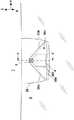
以下、第一実施形態に係る車両用制御装置20について説明する。図1(A)及び図1(B)は一実施形態に係る車両1の平面図及び側面図である。なお、各図において矢印Xは車両1の前後方向を示し、矢印Yは車両1の車幅方向を示す。矢印Zは上下方向を示す。<First embodiment>
<Configuration of vehicle control device>
Hereinafter, the
車両1は一例としてセダンタイプの四輪の乗用車である。車両1は、フロントウィンドウ5に隣接した前列に2つのシート、後列に2つのシートを有し、前列の右側のシートが運転席、左側のシートが助手席である。車両1は各シートに隣接して合計4つのドアを有している。車両1の前部には駆動ユニット6が設けられている。駆動ユニット6は、車両1の推進力を発揮する駆動源を含む。駆動源は本実施形態の場合、エンジン(内燃機関)である。駆動ユニット6は、エンジンの他に自動変速機を含む。なお、駆動源としては、電動モータ等、他の駆動源を採用してもよいし、内燃機関と電動モータとの組み合わせのように、複数の装置の組み合わせで駆動源を構成してもよい。また、本説明では四輪の車両を例示して説明するが、二輪自動車や船舶等の他の移動体に適用することも可能である。 The
車両1の前部には車室内の空調を行う空調装置9が設けられている。空調装置9は、乗員の操作に基づいて冷暖房や除湿、換気等を行う。乗員の操作は、例えば車室内のダッシュボードに設けられたスイッチ(不図示)によって行われる。また、空調装置9は、車室内の空調状態を内気循環状態と外気導入状態とに切り替え可能である。本実施形態では、空調装置9は、その作動モードとして内気循環モードと外気導入モードを有する。空調装置9は、内気循環モードのときは車室内の空気を循環し、外気導入モードのときは車外から車室内へ空気を供給する。 An
図2及び図3を併せて参照する。図2は、撮影装置3及びヒータ4をフロントウィンドウ5の外側から見た図である。また、図3は、図2のII−II線断面図である。 Please refer to FIG. 2 and FIG. 3 together. FIG. 2 is a view of the photographing
車両1は、車両1の周辺を撮影する撮影装置3を備える。本実施形態では撮影装置3は車両1の前方の画像を撮影する。撮影装置3は、例えば、イメージセンサ等の撮像素子と、レンズ等の光学系とを備えたカメラである。本実施形態の場合、撮影装置3の撮影画像は、例えば車両1の前方の障害物の検知や、道路区画線(例えば白線)の認識等に用いられる。 The
また、本実施形態の場合、撮影装置3は、車両1の車室内側においてルーフ7の前部にブラケット30を介して設けられている。また、撮影装置3は、フロントウィンドウ5を構成する透過部50を介して車両1の前方を撮影可能である。図2の方向から見ると、撮影装置3はそのレンズ部分が露出しており、本体部分はブラケット30及びヒータ4の後方又は下方に隠れている。 Further, in the case of the present embodiment, the
透過部50の下方には、透過部50をそれぞれ加熱可能なヒータ4が設けられている。本実施形態では、ヒータ4はSLS(迷光防止構造)301の裏側に貼り付けられている。SLS301は、透過部50を透過して車室内側に入射した光の乱反射を抑制するための板状の部材である。SLS301は表側が透過部50に対向するように設けられ、裏側にヒータ4が貼り付けられている。つまり、本実施形態ではヒータ4は、SLS301を介してブラケット30に設けられている。 Below the
ヒータ4は、透過部50の曇りを除去又は防止するためのものである。例えば、外気温が低いときに車室内で暖房を使用すると、車室内外の温度の差が大きくなり車両の窓ガラス等に結露による曇りが生じる場合がある。また、例えば、外気温が低い場合には車外側表面に付着する氷や霜によっても窓ガラス等の曇りが生じる場合がある。透過部50に曇りが発生すると、撮影装置3による撮影画像が不鮮明になり、走行支援における障害物や区画線等の検知に撮影画像を用いることができなくなる場合がある。そこで、本実施形態では、撮影装置3に対してヒータ4を設けることで、透過部50の曇りを除去又は防止している。 The
ヒータ4は例えば電熱ヒータである。本実施形態の場合、ヒータ4は板状の形状をしており、板状の部分に配置された電熱線に電流が流れることによりその周囲を加熱することができる。なお、ヒータ4の構成は例示であって、他の構成も採用可能である。例えば、フロントウィンドウ5自体の透過部50の周囲に電熱線を設けてもよい。 The
ブラケット30は、撮影装置3及びヒータ4を支持する。ブラケット30は、透過部50に対向して設けられる壁部30aと、壁部30aから透過部50の方向へと延びて設けられる壁部30bとを含む。本実施形態の場合、透過部50、壁部30a及び壁部30bにより空間30cが画定される。なお、ブラケット30及び壁部30a、30bの構成は例示であって適宜変更可能である。 The
また、本実施形態では壁部30aの前側には空間30cと車室内のその余の空間とが連通する連通部30dが形成されている。言い換えると、壁部30aの前側端部と窓部5(透過部50)との間に隙間が形成されている。このような構成により車両1の前部に設けられた空調装置9からの空気が図3の矢印Aで示すように窓部5に沿って空間30c内へと導入される。すなわち、連通部30dは、空調装置9からの空気を空間30c内へと導入可能に設けられている。このような構成により、空調装置9からの空気が直接透過部50に当たるため、より効果的に透過部50の曇りを防止又は除去することができる。 Further, in the present embodiment, a
なお、本実施形態では、撮影装置3及びヒータ4を支持するブラケット30はルーフ7に設けられているが、ブラケット30がフロントウィンドウ5に接着される構成も採用可能である。また、本実施形態では撮影装置3が1つ設けられているが、撮影装置3を2つ以上設けてそれぞれに対してヒータ4を設け、これらをブラケットにより支持する構成も採用可能である。なお、撮影装置3及びヒータ4を複数設ける場合、ブラケットが撮影装置3及びヒータ4の対ごとに複数設けられてもよい。また、単一のブラケットが複数の撮影装置3及びヒータ4を支持するように設けられてもよい。 In addition, in the present embodiment, the
図4は車両1の車両用制御装置20の構成例を示すブロック図である。車両用制御装置20は車両1の各デバイスの制御を行うユニットであり、図4には後述する本実施形態との特徴との関係で必要な構成が図示されている。 FIG. 4 is a block diagram showing a configuration example of the
車両用制御装置20は、制御ユニット21を含む。制御ユニット21は複数のECU(Electric Control Unit)22〜26を含む。各ECUは車内ネットワークNTを介して互いに通信可能に接続されている。各ECUは、CPUに代表されるプロセッサ、半導体メモリ等の記憶デバイス、外部デバイスとのインタフェース等を含む。記憶デバイスにはプロセッサが実行するプログラムやプロセッサが処理に使用するデータ等が格納される。各ECUはプロセッサ、記憶デバイスおよびインタフェース等を複数備えていてもよい。なお、ECUの数や、担当する機能については適宜設計可能であり、本実施形態よりも細分化したり、あるいは、統合したりすることが可能である。なお、図4においてはECU22〜26の代表的な機能の名称を付している。例えば、ECU22には「空調制御ECU」と記載している。 The
ECU22は、空調装置9の作動を制御する。例えばECU22は、空調装置9の作動及び停止、冷暖房の切り替え、並びに内気循環モードと外気導入モードとの切り替えを制御する。これらの制御は、例えば車内温度等の車内状態や、乗員の操作をECU25(入力ECU)が受け付けた乗員からの操作に基づいて行われる。ECU23は、撮影装置3及び図示しない他の検知ユニットの検知結果に基づいて、車両1の走行制御として走行支援(換言すると運転支援)を行う。ECU24はヒータ4の作動を制御する。例えば、ECU24は、ヒータ4の出力調整やオン・オフの切り替え等、ヒータ4の作動に関する制御を実行する。例えば、ECU24は、後述する図5のフローチャートに従ってヒータ4の作動を制御する。ECU25は、入力装置12に対する乗員の指示を受け付ける。例えば、入力装置12には、駆動ユニット6の始動をするイグニションスイッチや、空調装置9のオン・オフ、冷暖房切り替え、内気循環モードと外気導入モードとの切り替えを指示するスイッチが含まれる。また、ECU26はセンサ15を制御し、その検知結果を取得する。センサ15には、後述する説明との関係でいうと、外気温検知を行う外気温センサ(以下、外気温センサ15)が含まれる。 The
<制御ユニットの処理例>
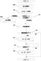
制御ユニット21の処理例について説明する。図5はECU24(ヒータ制御ECU)が実行するヒータ4の作動時の処理の例を示すフローチャートである。なお、本フローチャートは、空調装置9が作動を開始(A/Cオン)すると開始する。<Processing example of control unit>
A processing example of the
上述のように、外気温が低いときに車室内で暖房を使用すると、車室内外の温度の差が大きくなり車両の窓ガラス等に結露による曇りが生じる場合がある。また、この曇りは車室内の湿度が高いほど発生しやすくなる。一方で、空調装置9により車室内の空調状態を内気循環状態と外気導入状態を切り替え可能な場合、外気導入状態よりも内気循環状態の方が車室内の湿度が高くなりやすい。したがって、空調装置9が作動している場合、外気導入状態よりも内気循環状態の方が曇りも発生しやすくなる。 As described above, when heating is used in the vehicle interior when the outside air temperature is low, the temperature difference between the inside and outside of the vehicle interior becomes large, and the window glass of the vehicle may be fogged due to dew condensation. In addition, this cloudiness is more likely to occur as the humidity inside the vehicle is higher. On the other hand, when the
そこで、本実施形態では、内気循環状態と外気導入状態とでヒータ4について異なる制御を行うことにより、より効果的に曇りを除去又は防止している。本実施形態の場合、ヒータ4を作動させるための外気温についての条件が内気循環状態と外気導入状態とで異なっている。すなわち、本実施形態では、ECU24は外気温が所定温度閾値以下の場合にヒータ4の作動を開始させる。そして、ECU24は、その所定温度閾値が内気循環状態と外気導入状態とで異なるように制御している。本実施形態の場合、外気導入状態における温度閾値をT1、内気循環状態における温度閾値をT2とすると、T1<T2となるように閾値が設定されている。これにより、透過部50に曇りの発生しやすい内気循環状態でヒータ4の作動を開始しやすくなり、より効果的に曇りを除去又は防止することができる。なお、T1及びT2は車両1の構成や使用地域等によって適宜変更可能であるが、一例として、T1を10℃、T2を15℃に設定可能であり、それ以上、又はそれ以下でもよい。 Therefore, in the present embodiment, different control is performed for the
図5において、S1ではECU24は、温度閾値の初期化を行う。本実施形態では、車室内の空調状態が外気導入状態のときの温度閾値T1を初期値としている。よって、ECU24は温度閾値をT1に設定する。なお、内気循環状態のときの温度閾値T2を初期値とする構成も採用可能である。 In FIG. 5, in S1, the
S2では、ECU24は、空調装置9の作動情報をECU22から取得する。S3では、ECU24は、S2で取得した作動情報から空調装置9が内気循環モードであるか外気導入モードであるかを判定する。ECU24は、空調装置9が内気循環モードである場合にはS4へ進み、外気導入モードである場合にはS5に進む。 In S2, the
S4では、ECU24は、ヒータ4の作動を開始するための温度閾値を変更する。本実施形態では、ECU24は温度閾値をT2(>T1)に設定する。これにより、内気循環モードでは外気導入モードよりも高い温度閾値に設定されるので、湿度の上昇しやすい内気循環モードでヒータ4の作動が開始しやすくなり、より効果的に透過部50の曇りを除去又は防止することができる。 In S4, the
S5では、ECU24は、外気温センサ15が検知した外気温(以下、外気温T3)をECU26から取得する。S6では、ECU24は、外気温T3が温度閾値以下であるか否かを判定する。外気温T3が温度閾値より高い場合(T3>T1又はT2)、ECU24は一回の処理を終了する。一方、外気温が温度閾値以下の場合(T3≦T1又はT2)、ECU24はS7へ進む。 In S5, the
S7では、ECU24はヒータ4の作動を開始(オン)してS8に進む。S8では、ECU24は、ヒータ4による透過部50の加熱が完了したか否かを判定する。ECU24は、ヒータ4による加熱が完了した場合にはS9に進み、加熱が完了していない場合には作動が完了するまでS8の判定を繰り返す。本実施形態の場合、ヒータ4が所定時間作動した場合に加熱が完了したと判定する。また、本実施形態の場合、ヒータ4の作動中に外気温が所定温度以上となった場合にもそれ以上加熱をしなくてもよいとしてヒータ4による加熱が完了したと判定する。上記の判定条件は適宜変更可能である。一例として、ECU24は、ヒータ4が15分作動した又は外気温が10℃以上となった場合にヒータ4による加熱が完了したと判定してもよい。また、上記の判定には外気導入状態と内気循環状態とで同じ条件を用いてもよく、異なる条件を用いてもよい。例えば、外気導入状態と比較して内気循環状態ではヒータ4による加熱が完了したと判定するための所定時間を長くしてもよい。S10では、ECU24は、ヒータ4の作動を終了(オフ)して処理を終了する。 In S7, the
以上説明した処理によれば、ECU24は、車室内の空調状態が内気循環の場合と外気導入状態の場合とでヒータを作動するための外気温の閾値が異なるように制御を行う。これにより、曇りの発生しやすい内気循環時により高い外気温でヒータを作動させるので、より効果的に曇りを除去又は防止することができる。 According to the processing described above, the
<第二実施形態>
第一実施形態では外気温が所定温度閾値以下の場合にヒータ4の作動を開始しているが、第二実施形態では、外気温T3の所定時間当たりの変化量ΔT3が所定閾値以上の場合にヒータの作動を開始させる点で第一実施形態と異なる。なお、本実施形態の場合、変化量ΔT3は所定時間経過後に外気温が低下する場合を正とする。つまり、ΔT3は外気温T3の所定時間当たりの温度の低下量であり、その低下量が所定値以上の場合にヒータの作動を開始させる。<Second embodiment>
In the first embodiment, the operation of the
例えば、運転中にトンネルに進入した場合や急な降雨があった場合には、比較的外気温が高くても急な温度変化により窓部5に曇りが発生することがある。また、このような場合でも、外気導入状態に比べて内気循環状態で曇りが発生しやすい。そこで、第二実施形態では、外気温T3の所定時間当たりの変化量ΔT3が所定閾値以上の場合にヒータ4の作動を開始させる。特に、本実施形態では所定時間当たりの変化量ΔT3が所定閾値以上の場合にヒータ4の作動を開始させる。また、曇りの発生しやすい内気循環状態では、外気導入状態と比較して所定閾値を小さくしている。すなわち、内気循環状態では外気導入状態と比較して外気温の低下量が小さくてもヒータ4の作動を開始させることにより、より効果的に窓部5(透過部50)の曇りを除去又は防止することができる。 For example, when entering a tunnel during driving or when there is a sudden rainfall, the
図6は、第二実施形態に係るECU24が実行するヒータ4の作動時の処理の例を示すフローチャートである。以下、第一実施形態と同じ処理については同一の符号を付し、説明を省略する場合がある。 FIG. 6 is a flowchart showing an example of processing executed by the
S11ではECU24は、閾値の初期化を行う。本実施形態では、車室内の空調状態が外気導入状態のときの温度変化閾値ΔT1を初期値としている。よって、ECU24は閾値をΔT1に設定する。なお、内気循環状態のときの閾値ΔT2を初期値とする構成も採用可能である。また、温度変化閾値ΔT1及びΔT2は適宜変更可能である。一例として、ΔT1を10℃/30秒、ΔT2を5℃/30秒に設定可能であり、それ以上、又はそれ以下でもよい。 In S11, the
S14では、ECU24は、ヒータ4の作動を開始するための閾値を変更する。本実施形態では、ECU24は閾値をΔT2(<ΔT1)に設定する。これにより、内気循環モードでは外気導入モードよりも閾値が小さく設定されるので、湿度の上昇しやすい内気循環モードでヒータ4の作動が開始しやすくなり、より効果的に透過部50の曇りを除去又は防止することができる。 In S14, the
S15では、ECU24は、外気温センサ15が検知した外気温T3をECU26から取得し、その変化量を算出する。本実施形態では、外気温の低下量を判定条件とするため、ECU24は、所定時間経過前後の外気温を取得する。外気温の低下量を見る所定時間は適宜設定可能であるが、例えば30秒に設定可能であり、それ以上又はそれ以下でもよい。ECU24は、取得した所定時間経過前後の外気温T3から外気温の変化量ΔT3を算出する。 In S15, the
S16で、ECU24は、ΔT3が閾値以上であるか否かを判定する。外気温の変化量ΔT3が所定閾値より小さい場合(ΔT3<ΔT1又はΔT2)、ECU24は一回の処理を終了する。一方、所定閾値以上の場合(ΔT3≧ΔT1又はT2)、ECU24はS7へ進む。 In S16, the
以上説明したように、本実施形態によれば、内気循環状態では外気導入状態と比較して小さい外気温の低下量でもヒータ4の作動を開始させるので、より効果的に窓部5(透過部50)の曇りを除去又は防止することができる。 As described above, according to the present embodiment, the operation of the
<第三実施形態>
第一及び第二実施形態では、内気循環状態と外気導入状態とでヒータ4の作動を開始させるための条件が異なるが、ヒータ4の作動中の作動条件が異なる構成も採用可能である。第三実施形態では、内気循環状態では外気導入状態よりもヒータ作動時の出力を高くすることにより、窓部5(透過部50)に曇りの発生しやすい内気循環状態の場合により効果的に窓部5(透過部50)の曇りの発生を除去又は防止することができる。<Third embodiment>
In the first and second embodiments, the conditions for starting the operation of the
図7は、第三実施形態に係るECU24が実行するヒータ4の作動時の処理の例を示すフローチャートである。以下、第一実施形態と同じ処理については同一の符号を付し、説明を省略する場合がある。 FIG. 7 is a flowchart showing an example of a process executed by the
S21では、ECU24は、ヒータ出力の初期化を行う。本実施形態では、車室内の空調状態が外気導入状態のときのヒータ出力P1を初期値としている。よって、ECU24はヒータ出力をP1に設定する。なお、内気循環状態のときのヒータ出力P2を初期値とする構成も採用可能である。 In S21, the
S24では、ECU24は、ヒータ4のヒータ出力を変更する。本実施形態では、ヒータ出力をP2(>P1)に変更する。これにより、内気循環モードでは外気導入モードよりも高いヒータ出力に設定されるので、湿度の上昇しやすい内気循環モードでヒータ4のヒータ出力が高くなり、より効果的に透過部50の曇りを除去又は防止することができる。 In S24, the
<第四実施形態>
第四実施形態は、内気循環状態と外気導入状態とでヒータ4の作動中の作動条件が異なる点で第三実施形態と同様である。しかし、第四実施形態では、ヒータ4が間欠的に作動可能であり、その作動間隔の条件が内気循環状態と外気導入状態とで異なるようにヒータ4の作動が制御されている。<Fourth Embodiment>
The fourth embodiment is similar to the third embodiment in that the operating conditions during operation of the
透過部50が過剰に加熱されることの防止やエネルギー消費の低減等の観点からヒータ4のON/OFFを繰り返してヒータ4を間欠的に作動させる場合がある。本実施形態では、内気循環状態と外気導入状態とでヒータ4の間欠作動中のヒータON時間及びOFF時間(以下、間欠作動時間と呼ぶことがある)が異なるように制御が行われる。つまり、内気循環状態と外気導入状態とで間欠間隔が異なるように制御が行われる。これにより、より効果的に窓部5(透過部50)曇りを抑制することができる。 From the viewpoint of preventing the
図8は、第四実施形態に係るECU24が実行するヒータ4の作動時の処理の例を示すフローチャートである。以下、第一実施形態と同じ処理については同一の符号を付し、説明を省略する場合がある。 FIG. 8 is a flowchart showing an example of a process executed by the
S31では、ECU24は、ヒータ間欠作動時間の初期化を行う。本実施形態では、車室内の空調状態が外気導入状態のときのヒータ間欠作動時間X1を初期値としている。よって、ECU24はヒータ間欠作動時間をX1に設定する。なお、内気循環状態のときのヒータ間欠作動時間X2を初期値とする構成も採用可能である。 In S31, the
S34では、ECU24は、ヒータ4のヒータ間欠作動時間を変更する。本実施形態では、ヒータ間欠作動時間をX2に変更する。本実施形態では、X2はX1と比較してヒータOFF時間に対するヒータON時間の割合が高くなるように設定されている。X1及びX2のヒータON時間及びヒータOFF時間は適宜設定可能である。しかしながら、一例として、X1では、ヒータON時間及びヒータOFF時間が共に15分であるのに対し、X2のヒータON時間は15分、ヒータOFF時間は5分というように設定可能である。このように、内気循環状態では外気導入状態に比べて間欠作動中のヒータON時間の割合が相対的に大きくなるように設定することで、透過部50の温度が低下しにくくなり、より効果的に透過部50の曇りを抑制することができる。また、比較的透過部50に曇りが発生しにくい外気導入状態ではヒータOFF時間の割合が相対的に大きくなるように設定することで、ヒータ4の作動によるエネルギー消費を抑えることができる。 In S34, the
また、間欠時間の設定としては、X1ではヒータON時間及びヒータOFF時間ともに15分、X2ではヒータON時間及びヒータOFF時間ともに5分というように、X2の方が短い間隔でON/OFF切り替えるようにしてもよい。すなわち、1周期当たりの時間を短くすることにより、ヒータOFF時の透過部50の温度低下を抑えられるので、より効果的に透過部50の曇りを抑制することができる。 Further, as the setting of the intermittent time, the heater ON time and the heater OFF time are both 15 minutes for X1, and the heater ON time and the heater OFF time are both 5 minutes for X2, so that X2 is switched ON/OFF at shorter intervals. You may That is, by shortening the time per cycle, the temperature drop of the
また、本実施形態の場合、S8での加熱が完了したか否かの判定は、上述の所定時間の経過や外気温による判定の他、ヒータON/OFFの切り替えが所定回数行われたか等によって行ってもよい。 In addition, in the case of the present embodiment, whether or not the heating in S8 is completed is determined by whether the heater ON/OFF is switched a predetermined number of times, in addition to the determination based on the elapse of the predetermined time or the outside air temperature. You can go.
<その他の実施形態>
第一実施形態ないし第四実施形態に係る制御は適宜組み合わせ可能である。例えば、第一及び第二実施形態はヒータの作動を開始するための制御であり、第三及び第四実施形態はヒータ作動中の制御である。したがって、第一及び第二実施形態のいずれかと、第三及び第四実施形態のいずれかとを組み合わせてもよい。これにより、ヒータの作動開始及び作動中により効果的に曇りを除去又は防止することができる。<Other embodiments>
The controls according to the first to fourth embodiments can be combined as appropriate. For example, the first and second embodiments are controls for starting the operation of the heater, and the third and fourth embodiments are controls during the operation of the heater. Therefore, any one of the first and second embodiments and any one of the third and fourth embodiments may be combined. As a result, it is possible to effectively remove or prevent the fogging during the operation start and during the operation of the heater.
<実施形態のまとめ>
上記実施形態は以下の移動体用制御装置を少なくとも開示する。<Summary of Embodiments>
The above embodiment discloses at least the following moving body control device.
1.上記実施形態の移動体用制御装置(例えば20)は、
移動体(例えば1)の窓部(例えば5)を構成する透過部(例えば50)を介して前記移動体の周辺を撮影する撮影手段(例えば3)と、
前記透過部を加熱可能なヒータ(例えば4)と、
前記移動体の車室内の空調状態を内気循環状態と外気導入状態とに切り替え可能な空調手段(例えば9)と、
前記ヒータを制御する制御手段(例えば24)と、を備え、
前記制御手段は、
前記空調状態が前記内気循環状態である場合と前記外気導入状態である場合とで、前記ヒータの作動中の条件が異なる制御を行い、
前記空調状態が前記内気循環状態である場合、前記空調状態が前記外気導入状態である場合よりも、作動中の前記ヒータの出力を高くする。1. The moving body control device (for example, 20) of the above-described embodiment,
An image capturing unit (e.g., 3) that captures an image of the periphery of the moving body (e.g., 1) through a transmissive portion (e.g., 50) forming a window (e.g., 5) of the moving body,
With a heater (for example, 4) capable of heating the transmission part,
Air-conditioning means capable of switching the air-conditioning state of the vehicle interior of the moving body between an inside air circulation state and an outside air introduction state (for example, 9),
And a control means (for example, 24) for controlling the heater,
The control means is
In the case where the air-conditioning state is the inside air circulation state and the case where the outside air is introduced, the condition during operation of the heater is controlled differently,
When the air conditioning state is the inside air circulation state, the output of the heater in operation is made higher than when the air conditioning state is the outside air introduction state.
この実施形態によれば、内気循環状態と外気導入状態とでヒータの制御条件が異なるので、窓部の曇りの発生しやすさに応じてヒータを制御することができる。したがって、より効果的に撮影装置の視野内の窓部の曇り、すなわち透過部の曇り、を除去又は防止することができる。また、この実施形態によれば、内気循環状態と外気導入状態でヒータ作動中の条件が異なるので、窓部の曇りの発生しやすさに応じてヒータの作動を制御することができる。したがって、より効果的に透過部の曇りを除去又は防止することができる。また、この実施形態によれば、車室内の湿度が高くなりやすく窓部に曇りが発生しやすい内気循環状態でヒータの出力が高くなる。したがって、より効果的に透過部の曇りを除去又は防止することができる。 According to this embodiment, since the control condition of the heater is different between the inside air circulation state and the outside air introduction state, it is possible to control the heater according to the likelihood of fogging of the window. Therefore, it is possible to more effectively remove or prevent the fogging of the window portion within the field of view of the imaging device, that is, the fogging of the transmission portion. Further, according to this embodiment, since the condition during heater operation is different between the inside air circulation state and the outside air introduction state, it is possible to control the operation of the heater according to the likelihood of fogging of the window. Therefore, it is possible to more effectively remove or prevent the fogging of the transmission part. Further, according to this embodiment, the output of the heater is increased in the inside air circulation state in which the humidity in the vehicle compartment is likely to be high and the window is likely to be fogged. Therefore, it is possible to more effectively remove or prevent the fogging of the transmission part.
2.上記実施形態の移動体用制御装置(例えば20)は、
移動体(例えば1)の窓部(例えば5)を構成する透過部(例えば50)を介して前記移動体の周辺を撮影する撮影手段(例えば3)と、
前記透過部を加熱可能なヒータ(例えば4)と、
前記移動体の車室内の空調状態を内気循環状態と外気導入状態とに切り替え可能な空調手段(例えば9)と、
前記ヒータを制御する制御手段(例えば24)と、を備え、
前記制御手段は、
前記空調状態が前記内気循環状態である場合と前記外気導入状態である場合とで、前記ヒータの作動中の条件が異なる制御を行い、
前記ヒータを間欠的に作動可能であり、かつ、かつ、前記空調状態が前記内気循環状態である場合には前記外気導入状態である場合よりも間欠作動中の前記ヒータのオフ時間が短くなるように制御を行う。2. The moving body control device (for example, 20) of the above-described embodiment,
An image capturing unit (e.g., 3) that captures an image of the periphery of the moving body (e.g., 1) through a transmissive portion (e.g., 50) forming a window (e.g., 5) of the moving body,
With a heater (for example, 4) capable of heating the transmission part,
Air-conditioning means capable of switching the air-conditioning state of the vehicle interior of the moving body between an inside air circulation state and an outside air introduction state (for example, 9),
And a control means (for example, 24) for controlling the heater,
The control means is
In the case where the air-conditioning state is the inside air circulation state and the case where the outside air is introduced, the condition during operation of the heater is controlled differently,
When the heater can be operated intermittently, and when the air conditioning state is the inside air circulation state, the off time of the heater during the intermittent operation is shorter than when the heater is in the outside air introduction state. Control.
この実施形態によれば、間欠作動時のヒータの間欠間隔が、前記空調状態が前記内気循環状態である場合と前記外気導入状態である場合とで異なる。したがって、窓部の曇りの発生しやすさに応じて異なる制御が行われるので、より効果的に透過部の曇りを除去又は防止することができる。とくに、内気循環状態では、間欠作動中のヒータのオフの時間がより短くなるので、ヒータがオフの間に透過部の温度が下がりにくくなり、より効果的に透過部の曇りを除去又は防止することができる。 According to this embodiment, the intermittent interval of the heater at the time of intermittent operation is different depending on whether the air conditioning state is the inside air circulation state or the outside air introduction state. Therefore, different control is performed depending on the likelihood of fogging of the window portion, and thus it is possible to more effectively remove or prevent fogging of the transmission portion. In particular, in the internal air circulation state, the heater is turned off for a shorter time during the intermittent operation, so that the temperature of the permeation part is less likely to drop while the heater is off, and the fogging of the permeation part is more effectively removed or prevented. be able to.
3.上記実施形態の移動体用制御装置は、
前記制御手段は、前記内気循環状態である場合には、前記外気導入状態である場合よりも前記間欠作動中の前記ヒータの前記オフ時間に対するオン時間の割合が大きくなるよう制御を行うこと。3. The moving body control device of the above-described embodiment,
In the inside air circulation state, the control means performs control such that the ratio of the ON time to the OFF time of the heater during the intermittent operation is larger than that in the outside air introduction state.
この実施形態によれば、間欠作動中のヒータのオフ時間に対するオン時間の割合が大きくなるので、透過部50の温度が低下しにくくなり、より効果的に透過部50の曇りを抑制することができる。 According to this embodiment, since the ratio of the ON time to the OFF time of the heater during the intermittent operation is large, the temperature of the
4.上記実施形態の移動体用制御装置は、前記制御手段は、前記内気循環状態である場合には、前記外気導入状態である場合よりも前記間欠作動中の前記ヒータの前記オフ時間に対するオン時間の割合が大きくなるよう制御を行う。 4. The moving body control device of the above embodiment, the control means, in the inside air circulation state, the on time with respect to the off time of the heater during the intermittent operation than in the outside air introduction state Control is performed to increase the ratio.
この実施形態によれば、間欠作動中の1周期当たりの時間が短くなるので、ヒータOFF時の透過部50の温度低下を抑えられ、より効果的に透過部50の曇りを抑制することができる。 According to this embodiment, since the time per one cycle during the intermittent operation is shortened, the temperature drop of the
5.上記実施形態の移動体用制御装置は、
前記撮影手段及び前記ヒータを支持するブラケット(例えば30)をさらに備え、
該ブラケットは壁部(例えば30a,30b)を有し、
該壁部と前記透過部とが空間(例えば30c)を画定し、
前記壁部には、前記空調手段からの空気が前記空間内へ導入可能な連通部(例えば30d)が設けられている。5. The moving body control device of the above-described embodiment,
Further comprising a bracket (for example, 30) that supports the photographing means and the heater,
The bracket has a wall portion (for example, 30a, 30b),
The wall portion and the transmission portion define a space (for example, 30c),
The wall portion is provided with a communication portion (for example, 30d) capable of introducing air from the air conditioning unit into the space.
この実施形態によれば、空調装置からの空気が連通部を通過して空間に導入されて透過部に直接当たるので、より効果的に透過部の曇りを防止又は除去することができる。 According to this embodiment, the air from the air conditioner passes through the communication section, is introduced into the space, and directly hits the transmission section, so that it is possible to more effectively prevent or remove the fogging of the transmission section.
本発明は上記の実施形態に制限されるものではなく、本発明の要旨の範囲内で、種々の変形・変更が可能である。 The present invention is not limited to the above embodiment, and various modifications and changes can be made within the scope of the gist of the present invention.
1 車両、3 撮影装置、4 ヒータ、20 車両用制御装置、24 ECU 1 vehicle, 3 photographing device, 4 heater, 20 vehicle control device, 24 ECU
Claims (5)
Translated fromJapanese前記透過部を加熱可能なヒータと、
前記移動体の車室内の空調状態を内気循環状態と外気導入状態とに切り替え可能な空調手段と、
前記ヒータを制御する制御手段と、を備え、
前記制御手段は、
前記空調状態が前記内気循環状態である場合と前記外気導入状態である場合とで、前記ヒータの作動中の条件が異なる制御を行い、
前記空調状態が前記内気循環状態である場合、前記空調状態が前記外気導入状態である場合よりも、作動中の前記ヒータの出力を高くする、
ことを特徴とする移動体用制御装置。An image capturing unit that captures an image of the periphery of the moving body via a transmitting unit that forms a window of the moving body,
A heater capable of heating the transmission part,
An air conditioning unit capable of switching the air conditioning state of the vehicle interior of the moving body between an inside air circulation state and an outside air introduction state,
A control means for controlling the heater,
The control means is
In the case where the air-conditioning state is the inside air circulation state and the case where the outside air is introduced, the condition during operation of the heater is controlled differently,
When the air conditioning state is the inside air circulation state, the output of the heater in operation is made higher than when the air conditioning state is the outside air introduction state,
A control device for a mobile body characterized by the above.
前記透過部を加熱可能なヒータと、
前記移動体の車室内の空調状態を内気循環状態と外気導入状態とに切り替え可能な空調手段と、
前記ヒータを制御する制御手段と、を備え、
前記制御手段は、
前記空調状態が前記内気循環状態である場合と前記外気導入状態である場合とで、前記ヒータの作動中の条件が異なる制御を行い、
前記ヒータを間欠的に作動可能であり、かつ、前記空調状態が前記内気循環状態である場合には前記外気導入状態である場合よりも間欠作動中の前記ヒータのオフ時間が短くなるように制御を行う、
ことを特徴とする移動体用制御装置。An image capturing unit that captures an image of the periphery of the moving body via a transmitting unit that forms a window of the moving body,
A heater capable of heating the transmission part,
An air conditioning unit capable of switching the air conditioning state of the vehicle interior of the moving body between an inside air circulation state and an outside air introduction state,
A control means for controlling the heater,
The control means is
In the case where the air-conditioning state is the inside air circulation state and the case where the outside air is introduced, the condition during operation of the heater is controlled differently,
Control so that the heater can be operated intermittently, and when the air conditioning state is the inside air circulation state, the off time of the heater during the intermittent operation is shorter than that in the outside air introduction state I do,
A control device for a mobile body characterized by the above.
該ブラケットは壁部を有し、
該壁部と前記透過部とが空間を画定し、
前記壁部には、前記空調手段からの空気が前記空間内へ導入可能な連通部が設けられている、
ことを特徴とする請求項1ないし4のいずれか1項に記載の移動体用制御装置。Further comprising a bracket that supports the photographing means and the heater,
The bracket has a wall,
The wall and the transparent portion define a space,
The wall section is provided with a communication section through which air from the air conditioning unit can be introduced into the space.
The control device for a mobile body according to any one of claims 1 to 4, wherein:
Priority Applications (3)
| Application Number | Priority Date | Filing Date | Title |
|---|---|---|---|
| JP2019009738AJP2020117070A (en) | 2019-01-23 | 2019-01-23 | Mobile controller |
| CN202010030565.XACN111469808A (en) | 2019-01-23 | 2020-01-13 | Control device for moving body |
| US16/741,949US11285779B2 (en) | 2019-01-23 | 2020-01-14 | Moving body control apparatus |
Applications Claiming Priority (1)
| Application Number | Priority Date | Filing Date | Title |
|---|---|---|---|
| JP2019009738AJP2020117070A (en) | 2019-01-23 | 2019-01-23 | Mobile controller |
Publications (1)
| Publication Number | Publication Date |
|---|---|
| JP2020117070Atrue JP2020117070A (en) | 2020-08-06 |
Family
ID=71608543
Family Applications (1)
| Application Number | Title | Priority Date | Filing Date |
|---|---|---|---|
| JP2019009738APendingJP2020117070A (en) | 2019-01-23 | 2019-01-23 | Mobile controller |
Country Status (3)
| Country | Link |
|---|---|
| US (1) | US11285779B2 (en) |
| JP (1) | JP2020117070A (en) |
| CN (1) | CN111469808A (en) |
Cited By (1)
| Publication number | Priority date | Publication date | Assignee | Title |
|---|---|---|---|---|
| JP2022179002A (en)* | 2021-05-21 | 2022-12-02 | 小島プレス工業株式会社 | In-vehicle camera heater fixing structure |
Families Citing this family (3)
| Publication number | Priority date | Publication date | Assignee | Title |
|---|---|---|---|---|
| JP7066645B2 (en)* | 2019-01-23 | 2022-05-13 | 本田技研工業株式会社 | Control device for mobile objects |
| JP2020117070A (en)* | 2019-01-23 | 2020-08-06 | 本田技研工業株式会社 | Mobile controller |
| JP7078578B2 (en)* | 2019-06-10 | 2022-05-31 | 本田技研工業株式会社 | Transportation equipment and vehicles |
Citations (7)
| Publication number | Priority date | Publication date | Assignee | Title |
|---|---|---|---|---|
| JPS63306952A (en)* | 1987-06-08 | 1988-12-14 | Nippon Denso Co Ltd | Demister device for vehicle |
| JPH0769037A (en)* | 1993-09-01 | 1995-03-14 | Naldec Kk | Air conditioner for vehicle |
| JP2004210155A (en)* | 2003-01-06 | 2004-07-29 | Mazda Motor Corp | Defogger control device for vehicle |
| JP2004210154A (en)* | 2003-01-06 | 2004-07-29 | Mazda Motor Corp | Defogger control device for vehicle |
| JP2004210156A (en)* | 2003-01-06 | 2004-07-29 | Mazda Motor Corp | Defogger control device for vehicle |
| JP2014101004A (en)* | 2012-11-20 | 2014-06-05 | Toyota Motor Corp | Mounting structure of vehicular sensor and system cooperation method |
| JP2017206098A (en)* | 2016-05-18 | 2017-11-24 | トヨタ自動車株式会社 | Vehicular imaging apparatus |
Family Cites Families (36)
| Publication number | Priority date | Publication date | Assignee | Title |
|---|---|---|---|---|
| US6009355A (en)* | 1997-01-28 | 1999-12-28 | American Calcar Inc. | Multimedia information and control system for automobiles |
| US7019275B2 (en)* | 1997-09-16 | 2006-03-28 | Gentex Corporation | Moisture sensor and windshield fog detector |
| US7224324B2 (en)* | 2000-03-27 | 2007-05-29 | Donnelly Corporation | Interactive automotive rearvision system |
| US6392218B1 (en)* | 2000-04-07 | 2002-05-21 | Iteris, Inc. | Vehicle rain sensor |
| US7446427B2 (en)* | 2003-05-20 | 2008-11-04 | Gentex Corporation | Rearview mirror system for accommodating a rain sensor |
| US7650864B2 (en)* | 2006-11-17 | 2010-01-26 | Magna Electronics Inc. | Remote starter for vehicle |
| US9301343B2 (en)* | 2008-02-19 | 2016-03-29 | Fuji Jukogyo Kabushiki Kaisha | Window-glass heating device |
| US8362398B2 (en)* | 2009-11-30 | 2013-01-29 | Nissan North America, Inc. | Vehicle radiant heating control system |
| JP5533274B2 (en)* | 2010-05-31 | 2014-06-25 | カルソニックカンセイ株式会社 | Radiant heating system for vehicles |
| JP2012056531A (en)* | 2010-09-13 | 2012-03-22 | Denso Corp | Radiation heating system for vehicle |
| US20120234932A1 (en)* | 2011-03-16 | 2012-09-20 | Denso Corporation | Vehicular heating system |
| US20120234930A1 (en)* | 2011-03-17 | 2012-09-20 | Ford Global Technologies, Llc | Automatic remote start/stop control strategy for vehicle heating and cooling systems |
| JP5370402B2 (en)* | 2011-03-28 | 2013-12-18 | 株式会社デンソー | Air conditioner for vehicles |
| DE102012205012A1 (en)* | 2011-07-12 | 2013-01-17 | Robert Bosch Gmbh | Camera system for use in a vehicle and vehicle with such a camera system |
| US20130079978A1 (en)* | 2011-09-22 | 2013-03-28 | Honda Motor Co., Ltd. | Preconditioning a vehicle |
| JP5895805B2 (en)* | 2012-05-23 | 2016-03-30 | 株式会社デンソー | Radiation heater device |
| JP5983495B2 (en)* | 2013-03-28 | 2016-08-31 | 株式会社デンソー | Radiation heater device |
| JP6127913B2 (en)* | 2013-03-29 | 2017-05-17 | 株式会社デンソー | Radiation heater device |
| US9724980B2 (en)* | 2014-08-20 | 2017-08-08 | Ford Global Technologies, Llc | Windshield defogging system and method |
| US9963112B2 (en)* | 2014-09-09 | 2018-05-08 | Ford Global Technologies, Llc | Window wiper system incorporating window moisture and torque sensors |
| US20190279447A1 (en)* | 2015-12-03 | 2019-09-12 | Autoconnect Holdings Llc | Automatic vehicle diagnostic detection and communication |
| FR3047456B1 (en)* | 2016-02-05 | 2018-03-02 | Valeo Systemes Dessuyage | OPTICAL DETECTION SYSTEM FOR A MOTOR VEHICLE AND DEVICE FOR CLEANING SUCH A SYSTEM |
| US9994175B2 (en)* | 2016-03-04 | 2018-06-12 | Honda Motor Co., Ltd. | System for preconditioning a vehicle and method thereof |
| JP6515871B2 (en)* | 2016-05-31 | 2019-05-22 | トヨタ自動車株式会社 | Window glass heating device |
| JP6402866B2 (en)* | 2016-08-29 | 2018-10-10 | トヨタ自動車株式会社 | Window glass heating device |
| CN107856642B (en)* | 2017-01-24 | 2020-07-07 | 大众问问(北京)信息科技有限公司 | Automobile auxiliary driving system camera defogging device |
| KR20180099187A (en)* | 2017-02-28 | 2018-09-05 | 주식회사 가린시스템 | System and method for controlling air conditioner of vehicle |
| JP6939535B2 (en)* | 2017-12-27 | 2021-09-22 | トヨタ自動車株式会社 | Vehicle photography equipment and heating equipment |
| FR3079627B1 (en)* | 2018-03-29 | 2021-07-09 | Delphi Tech Llc | OPTICAL DEVICE FOR VEHICLES INCLUDING A HEATING ELEMENT |
| US11040593B1 (en)* | 2018-10-28 | 2021-06-22 | Changhai Chen | Occupant safety systems to respond to current conditions and prevent injuries of animate objects |
| JP2020100291A (en)* | 2018-12-21 | 2020-07-02 | 本田技研工業株式会社 | Moving body |
| JP2020117070A (en)* | 2019-01-23 | 2020-08-06 | 本田技研工業株式会社 | Mobile controller |
| JP7066645B2 (en)* | 2019-01-23 | 2022-05-13 | 本田技研工業株式会社 | Control device for mobile objects |
| JP7140698B2 (en)* | 2019-03-05 | 2022-09-21 | 本田技研工業株式会社 | Fog suppressing device and its control method |
| KR102692323B1 (en)* | 2019-05-10 | 2024-08-08 | 현대자동차주식회사 | Vehicle and method for management to protect life thereof |
| US20210107334A1 (en)* | 2019-10-11 | 2021-04-15 | Augmented Radar Imaging, Inc. | Control Modification Based on Perceived Environmental Condition |
- 2019
- 2019-01-23JPJP2019009738Apatent/JP2020117070A/enactivePending
- 2020
- 2020-01-13CNCN202010030565.XApatent/CN111469808A/enactivePending
- 2020-01-14USUS16/741,949patent/US11285779B2/enactiveActive
Patent Citations (7)
| Publication number | Priority date | Publication date | Assignee | Title |
|---|---|---|---|---|
| JPS63306952A (en)* | 1987-06-08 | 1988-12-14 | Nippon Denso Co Ltd | Demister device for vehicle |
| JPH0769037A (en)* | 1993-09-01 | 1995-03-14 | Naldec Kk | Air conditioner for vehicle |
| JP2004210155A (en)* | 2003-01-06 | 2004-07-29 | Mazda Motor Corp | Defogger control device for vehicle |
| JP2004210154A (en)* | 2003-01-06 | 2004-07-29 | Mazda Motor Corp | Defogger control device for vehicle |
| JP2004210156A (en)* | 2003-01-06 | 2004-07-29 | Mazda Motor Corp | Defogger control device for vehicle |
| JP2014101004A (en)* | 2012-11-20 | 2014-06-05 | Toyota Motor Corp | Mounting structure of vehicular sensor and system cooperation method |
| JP2017206098A (en)* | 2016-05-18 | 2017-11-24 | トヨタ自動車株式会社 | Vehicular imaging apparatus |
Cited By (2)
| Publication number | Priority date | Publication date | Assignee | Title |
|---|---|---|---|---|
| JP2022179002A (en)* | 2021-05-21 | 2022-12-02 | 小島プレス工業株式会社 | In-vehicle camera heater fixing structure |
| JP7650723B2 (en) | 2021-05-21 | 2025-03-25 | 小島プレス工業株式会社 | Heater fixing structure for vehicle-mounted camera |
Also Published As
| Publication number | Publication date |
|---|---|
| CN111469808A (en) | 2020-07-31 |
| US11285779B2 (en) | 2022-03-29 |
| US20200231021A1 (en) | 2020-07-23 |
Similar Documents
| Publication | Publication Date | Title |
|---|---|---|
| US11912243B2 (en) | Window glass heating device | |
| JP5949490B2 (en) | Vehicle sensor mounting structure and system linkage method | |
| JP2020117070A (en) | Mobile controller | |
| US20170240138A1 (en) | Imaging system | |
| CN111200881B (en) | window glass heater | |
| JP7140698B2 (en) | Fog suppressing device and its control method | |
| JP7044692B2 (en) | Shooting system for mobile objects | |
| CN111347999A (en) | moving body | |
| JP7294032B2 (en) | Anti-fog system and anti-fog method | |
| JP7066645B2 (en) | Control device for mobile objects | |
| JP2020100294A (en) | Moving body | |
| CN111348001A (en) | moving body | |
| JP7066650B2 (en) | Anti-fog device and its control method | |
| JP7553425B2 (en) | Anti-fog system | |
| CN117301792A (en) | Vehicle warm air control method and device, electronic equipment and vehicle | |
| CN111717162B (en) | moving body | |
| CN111717161B (en) | Moving body | |
| CN115139984A (en) | Anti-fog system | |
| JP7368422B2 (en) | anti-fog system | |
| CN115139986B (en) | Defogging system | |
| JP2024030087A (en) | vehicle | |
| CN118306344A (en) | Windshield defogging method, system and device for front view module of vehicle |
Legal Events
| Date | Code | Title | Description |
|---|---|---|---|
| RD02 | Notification of acceptance of power of attorney | Free format text:JAPANESE INTERMEDIATE CODE: A7422 Effective date:20210103 | |
| A521 | Request for written amendment filed | Free format text:JAPANESE INTERMEDIATE CODE: A523 Effective date:20210125 | |
| A621 | Written request for application examination | Free format text:JAPANESE INTERMEDIATE CODE: A621 Effective date:20210329 | |
| A977 | Report on retrieval | Free format text:JAPANESE INTERMEDIATE CODE: A971007 Effective date:20220309 | |
| A131 | Notification of reasons for refusal | Free format text:JAPANESE INTERMEDIATE CODE: A131 Effective date:20220404 | |
| A521 | Request for written amendment filed | Free format text:JAPANESE INTERMEDIATE CODE: A523 Effective date:20220526 | |
| A131 | Notification of reasons for refusal | Free format text:JAPANESE INTERMEDIATE CODE: A131 Effective date:20220916 | |
| A02 | Decision of refusal | Free format text:JAPANESE INTERMEDIATE CODE: A02 Effective date:20230310 |