JP2020115136A - Sparse map for autonomous vehicle navigation - Google Patents
Sparse map for autonomous vehicle navigationDownload PDFInfo
- Publication number
- JP2020115136A JP2020115136AJP2020036234AJP2020036234AJP2020115136AJP 2020115136 AJP2020115136 AJP 2020115136AJP 2020036234 AJP2020036234 AJP 2020036234AJP 2020036234 AJP2020036234 AJP 2020036234AJP 2020115136 AJP2020115136 AJP 2020115136A
- Authority
- JP
- Japan
- Prior art keywords
- vehicle
- road
- navigation
- image
- autonomous
- Prior art date
- Legal status (The legal status is an assumption and is not a legal conclusion. Google has not performed a legal analysis and makes no representation as to the accuracy of the status listed.)
- Granted
Links
Images


Classifications
- G—PHYSICS
- G01—MEASURING; TESTING
- G01C—MEASURING DISTANCES, LEVELS OR BEARINGS; SURVEYING; NAVIGATION; GYROSCOPIC INSTRUMENTS; PHOTOGRAMMETRY OR VIDEOGRAMMETRY
- G01C21/00—Navigation; Navigational instruments not provided for in groups G01C1/00 - G01C19/00
- G01C21/38—Electronic maps specially adapted for navigation; Updating thereof
- G01C21/3804—Creation or updating of map data
- G01C21/3807—Creation or updating of map data characterised by the type of data
- G01C21/3815—Road data
- G01C21/3822—Road feature data, e.g. slope data
- G—PHYSICS
- G06—COMPUTING OR CALCULATING; COUNTING
- G06F—ELECTRIC DIGITAL DATA PROCESSING
- G06F16/00—Information retrieval; Database structures therefor; File system structures therefor
- G06F16/20—Information retrieval; Database structures therefor; File system structures therefor of structured data, e.g. relational data
- G06F16/29—Geographical information databases
- G—PHYSICS
- G01—MEASURING; TESTING
- G01C—MEASURING DISTANCES, LEVELS OR BEARINGS; SURVEYING; NAVIGATION; GYROSCOPIC INSTRUMENTS; PHOTOGRAMMETRY OR VIDEOGRAMMETRY
- G01C21/00—Navigation; Navigational instruments not provided for in groups G01C1/00 - G01C19/00
- G01C21/38—Electronic maps specially adapted for navigation; Updating thereof
- G01C21/3804—Creation or updating of map data
- G01C21/3833—Creation or updating of map data characterised by the source of data
- G01C21/3837—Data obtained from a single source
- B—PERFORMING OPERATIONS; TRANSPORTING
- B60—VEHICLES IN GENERAL
- B60W—CONJOINT CONTROL OF VEHICLE SUB-UNITS OF DIFFERENT TYPE OR DIFFERENT FUNCTION; CONTROL SYSTEMS SPECIALLY ADAPTED FOR HYBRID VEHICLES; ROAD VEHICLE DRIVE CONTROL SYSTEMS FOR PURPOSES NOT RELATED TO THE CONTROL OF A PARTICULAR SUB-UNIT
- B60W30/00—Purposes of road vehicle drive control systems not related to the control of a particular sub-unit, e.g. of systems using conjoint control of vehicle sub-units
- B60W30/10—Path keeping
- B—PERFORMING OPERATIONS; TRANSPORTING
- B60—VEHICLES IN GENERAL
- B60W—CONJOINT CONTROL OF VEHICLE SUB-UNITS OF DIFFERENT TYPE OR DIFFERENT FUNCTION; CONTROL SYSTEMS SPECIALLY ADAPTED FOR HYBRID VEHICLES; ROAD VEHICLE DRIVE CONTROL SYSTEMS FOR PURPOSES NOT RELATED TO THE CONTROL OF A PARTICULAR SUB-UNIT
- B60W30/00—Purposes of road vehicle drive control systems not related to the control of a particular sub-unit, e.g. of systems using conjoint control of vehicle sub-units
- B60W30/14—Adaptive cruise control
- B—PERFORMING OPERATIONS; TRANSPORTING
- B60—VEHICLES IN GENERAL
- B60W—CONJOINT CONTROL OF VEHICLE SUB-UNITS OF DIFFERENT TYPE OR DIFFERENT FUNCTION; CONTROL SYSTEMS SPECIALLY ADAPTED FOR HYBRID VEHICLES; ROAD VEHICLE DRIVE CONTROL SYSTEMS FOR PURPOSES NOT RELATED TO THE CONTROL OF A PARTICULAR SUB-UNIT
- B60W30/00—Purposes of road vehicle drive control systems not related to the control of a particular sub-unit, e.g. of systems using conjoint control of vehicle sub-units
- B60W30/18—Propelling the vehicle
- B—PERFORMING OPERATIONS; TRANSPORTING
- B60—VEHICLES IN GENERAL
- B60W—CONJOINT CONTROL OF VEHICLE SUB-UNITS OF DIFFERENT TYPE OR DIFFERENT FUNCTION; CONTROL SYSTEMS SPECIALLY ADAPTED FOR HYBRID VEHICLES; ROAD VEHICLE DRIVE CONTROL SYSTEMS FOR PURPOSES NOT RELATED TO THE CONTROL OF A PARTICULAR SUB-UNIT
- B60W40/00—Estimation or calculation of non-directly measurable driving parameters for road vehicle drive control systems not related to the control of a particular sub unit, e.g. by using mathematical models
- B60W40/02—Estimation or calculation of non-directly measurable driving parameters for road vehicle drive control systems not related to the control of a particular sub unit, e.g. by using mathematical models related to ambient conditions
- B60W40/06—Road conditions
- B—PERFORMING OPERATIONS; TRANSPORTING
- B60—VEHICLES IN GENERAL
- B60W—CONJOINT CONTROL OF VEHICLE SUB-UNITS OF DIFFERENT TYPE OR DIFFERENT FUNCTION; CONTROL SYSTEMS SPECIALLY ADAPTED FOR HYBRID VEHICLES; ROAD VEHICLE DRIVE CONTROL SYSTEMS FOR PURPOSES NOT RELATED TO THE CONTROL OF A PARTICULAR SUB-UNIT
- B60W60/00—Drive control systems specially adapted for autonomous road vehicles
- B60W60/001—Planning or execution of driving tasks
- B60W60/0015—Planning or execution of driving tasks specially adapted for safety
- B—PERFORMING OPERATIONS; TRANSPORTING
- B60—VEHICLES IN GENERAL
- B60W—CONJOINT CONTROL OF VEHICLE SUB-UNITS OF DIFFERENT TYPE OR DIFFERENT FUNCTION; CONTROL SYSTEMS SPECIALLY ADAPTED FOR HYBRID VEHICLES; ROAD VEHICLE DRIVE CONTROL SYSTEMS FOR PURPOSES NOT RELATED TO THE CONTROL OF A PARTICULAR SUB-UNIT
- B60W60/00—Drive control systems specially adapted for autonomous road vehicles
- B60W60/001—Planning or execution of driving tasks
- B60W60/0027—Planning or execution of driving tasks using trajectory prediction for other traffic participants
- B60W60/00274—Planning or execution of driving tasks using trajectory prediction for other traffic participants considering possible movement changes
- B—PERFORMING OPERATIONS; TRANSPORTING
- B62—LAND VEHICLES FOR TRAVELLING OTHERWISE THAN ON RAILS
- B62D—MOTOR VEHICLES; TRAILERS
- B62D15/00—Steering not otherwise provided for
- B62D15/02—Steering position indicators ; Steering position determination; Steering aids
- B62D15/025—Active steering aids, e.g. helping the driver by actively influencing the steering system after environment evaluation
- G—PHYSICS
- G01—MEASURING; TESTING
- G01C—MEASURING DISTANCES, LEVELS OR BEARINGS; SURVEYING; NAVIGATION; GYROSCOPIC INSTRUMENTS; PHOTOGRAMMETRY OR VIDEOGRAMMETRY
- G01C21/00—Navigation; Navigational instruments not provided for in groups G01C1/00 - G01C19/00
- G01C21/10—Navigation; Navigational instruments not provided for in groups G01C1/00 - G01C19/00 by using measurements of speed or acceleration
- G01C21/12—Navigation; Navigational instruments not provided for in groups G01C1/00 - G01C19/00 by using measurements of speed or acceleration executed aboard the object being navigated; Dead reckoning
- G01C21/14—Navigation; Navigational instruments not provided for in groups G01C1/00 - G01C19/00 by using measurements of speed or acceleration executed aboard the object being navigated; Dead reckoning by recording the course traversed by the object
- G—PHYSICS
- G01—MEASURING; TESTING
- G01C—MEASURING DISTANCES, LEVELS OR BEARINGS; SURVEYING; NAVIGATION; GYROSCOPIC INSTRUMENTS; PHOTOGRAMMETRY OR VIDEOGRAMMETRY
- G01C21/00—Navigation; Navigational instruments not provided for in groups G01C1/00 - G01C19/00
- G01C21/10—Navigation; Navigational instruments not provided for in groups G01C1/00 - G01C19/00 by using measurements of speed or acceleration
- G01C21/12—Navigation; Navigational instruments not provided for in groups G01C1/00 - G01C19/00 by using measurements of speed or acceleration executed aboard the object being navigated; Dead reckoning
- G01C21/16—Navigation; Navigational instruments not provided for in groups G01C1/00 - G01C19/00 by using measurements of speed or acceleration executed aboard the object being navigated; Dead reckoning by integrating acceleration or speed, i.e. inertial navigation
- G01C21/165—Navigation; Navigational instruments not provided for in groups G01C1/00 - G01C19/00 by using measurements of speed or acceleration executed aboard the object being navigated; Dead reckoning by integrating acceleration or speed, i.e. inertial navigation combined with non-inertial navigation instruments
- G01C21/1652—Navigation; Navigational instruments not provided for in groups G01C1/00 - G01C19/00 by using measurements of speed or acceleration executed aboard the object being navigated; Dead reckoning by integrating acceleration or speed, i.e. inertial navigation combined with non-inertial navigation instruments with ranging devices, e.g. LIDAR or RADAR
- G—PHYSICS
- G01—MEASURING; TESTING
- G01C—MEASURING DISTANCES, LEVELS OR BEARINGS; SURVEYING; NAVIGATION; GYROSCOPIC INSTRUMENTS; PHOTOGRAMMETRY OR VIDEOGRAMMETRY
- G01C21/00—Navigation; Navigational instruments not provided for in groups G01C1/00 - G01C19/00
- G01C21/10—Navigation; Navigational instruments not provided for in groups G01C1/00 - G01C19/00 by using measurements of speed or acceleration
- G01C21/12—Navigation; Navigational instruments not provided for in groups G01C1/00 - G01C19/00 by using measurements of speed or acceleration executed aboard the object being navigated; Dead reckoning
- G01C21/16—Navigation; Navigational instruments not provided for in groups G01C1/00 - G01C19/00 by using measurements of speed or acceleration executed aboard the object being navigated; Dead reckoning by integrating acceleration or speed, i.e. inertial navigation
- G01C21/165—Navigation; Navigational instruments not provided for in groups G01C1/00 - G01C19/00 by using measurements of speed or acceleration executed aboard the object being navigated; Dead reckoning by integrating acceleration or speed, i.e. inertial navigation combined with non-inertial navigation instruments
- G01C21/1656—Navigation; Navigational instruments not provided for in groups G01C1/00 - G01C19/00 by using measurements of speed or acceleration executed aboard the object being navigated; Dead reckoning by integrating acceleration or speed, i.e. inertial navigation combined with non-inertial navigation instruments with passive imaging devices, e.g. cameras
- G—PHYSICS
- G01—MEASURING; TESTING
- G01C—MEASURING DISTANCES, LEVELS OR BEARINGS; SURVEYING; NAVIGATION; GYROSCOPIC INSTRUMENTS; PHOTOGRAMMETRY OR VIDEOGRAMMETRY
- G01C21/00—Navigation; Navigational instruments not provided for in groups G01C1/00 - G01C19/00
- G01C21/20—Instruments for performing navigational calculations
- G—PHYSICS
- G01—MEASURING; TESTING
- G01C—MEASURING DISTANCES, LEVELS OR BEARINGS; SURVEYING; NAVIGATION; GYROSCOPIC INSTRUMENTS; PHOTOGRAMMETRY OR VIDEOGRAMMETRY
- G01C21/00—Navigation; Navigational instruments not provided for in groups G01C1/00 - G01C19/00
- G01C21/26—Navigation; Navigational instruments not provided for in groups G01C1/00 - G01C19/00 specially adapted for navigation in a road network
- G01C21/28—Navigation; Navigational instruments not provided for in groups G01C1/00 - G01C19/00 specially adapted for navigation in a road network with correlation of data from several navigational instruments
- G01C21/30—Map- or contour-matching
- G01C21/32—Structuring or formatting of map data
- G—PHYSICS
- G01—MEASURING; TESTING
- G01C—MEASURING DISTANCES, LEVELS OR BEARINGS; SURVEYING; NAVIGATION; GYROSCOPIC INSTRUMENTS; PHOTOGRAMMETRY OR VIDEOGRAMMETRY
- G01C21/00—Navigation; Navigational instruments not provided for in groups G01C1/00 - G01C19/00
- G01C21/26—Navigation; Navigational instruments not provided for in groups G01C1/00 - G01C19/00 specially adapted for navigation in a road network
- G01C21/34—Route searching; Route guidance
- G01C21/3407—Route searching; Route guidance specially adapted for specific applications
- G—PHYSICS
- G01—MEASURING; TESTING
- G01C—MEASURING DISTANCES, LEVELS OR BEARINGS; SURVEYING; NAVIGATION; GYROSCOPIC INSTRUMENTS; PHOTOGRAMMETRY OR VIDEOGRAMMETRY
- G01C21/00—Navigation; Navigational instruments not provided for in groups G01C1/00 - G01C19/00
- G01C21/26—Navigation; Navigational instruments not provided for in groups G01C1/00 - G01C19/00 specially adapted for navigation in a road network
- G01C21/34—Route searching; Route guidance
- G01C21/3446—Details of route searching algorithms, e.g. Dijkstra, A*, arc-flags or using precalculated routes
- G—PHYSICS
- G01—MEASURING; TESTING
- G01C—MEASURING DISTANCES, LEVELS OR BEARINGS; SURVEYING; NAVIGATION; GYROSCOPIC INSTRUMENTS; PHOTOGRAMMETRY OR VIDEOGRAMMETRY
- G01C21/00—Navigation; Navigational instruments not provided for in groups G01C1/00 - G01C19/00
- G01C21/26—Navigation; Navigational instruments not provided for in groups G01C1/00 - G01C19/00 specially adapted for navigation in a road network
- G01C21/34—Route searching; Route guidance
- G01C21/3453—Special cost functions, i.e. other than distance or default speed limit of road segments
- G01C21/3476—Special cost functions, i.e. other than distance or default speed limit of road segments using point of interest [POI] information, e.g. a route passing visible POIs
- G—PHYSICS
- G01—MEASURING; TESTING
- G01C—MEASURING DISTANCES, LEVELS OR BEARINGS; SURVEYING; NAVIGATION; GYROSCOPIC INSTRUMENTS; PHOTOGRAMMETRY OR VIDEOGRAMMETRY
- G01C21/00—Navigation; Navigational instruments not provided for in groups G01C1/00 - G01C19/00
- G01C21/26—Navigation; Navigational instruments not provided for in groups G01C1/00 - G01C19/00 specially adapted for navigation in a road network
- G01C21/34—Route searching; Route guidance
- G01C21/36—Input/output arrangements for on-board computers
- G01C21/3602—Input other than that of destination using image analysis, e.g. detection of road signs, lanes, buildings, real preceding vehicles using a camera
- G—PHYSICS
- G01—MEASURING; TESTING
- G01C—MEASURING DISTANCES, LEVELS OR BEARINGS; SURVEYING; NAVIGATION; GYROSCOPIC INSTRUMENTS; PHOTOGRAMMETRY OR VIDEOGRAMMETRY
- G01C21/00—Navigation; Navigational instruments not provided for in groups G01C1/00 - G01C19/00
- G01C21/26—Navigation; Navigational instruments not provided for in groups G01C1/00 - G01C19/00 specially adapted for navigation in a road network
- G01C21/34—Route searching; Route guidance
- G01C21/36—Input/output arrangements for on-board computers
- G01C21/3605—Destination input or retrieval
- G01C21/3623—Destination input or retrieval using a camera or code reader, e.g. for optical or magnetic codes
- G—PHYSICS
- G01—MEASURING; TESTING
- G01C—MEASURING DISTANCES, LEVELS OR BEARINGS; SURVEYING; NAVIGATION; GYROSCOPIC INSTRUMENTS; PHOTOGRAMMETRY OR VIDEOGRAMMETRY
- G01C21/00—Navigation; Navigational instruments not provided for in groups G01C1/00 - G01C19/00
- G01C21/26—Navigation; Navigational instruments not provided for in groups G01C1/00 - G01C19/00 specially adapted for navigation in a road network
- G01C21/34—Route searching; Route guidance
- G01C21/36—Input/output arrangements for on-board computers
- G01C21/3626—Details of the output of route guidance instructions
- G01C21/3644—Landmark guidance, e.g. using POIs or conspicuous other objects
- G—PHYSICS
- G01—MEASURING; TESTING
- G01C—MEASURING DISTANCES, LEVELS OR BEARINGS; SURVEYING; NAVIGATION; GYROSCOPIC INSTRUMENTS; PHOTOGRAMMETRY OR VIDEOGRAMMETRY
- G01C21/00—Navigation; Navigational instruments not provided for in groups G01C1/00 - G01C19/00
- G01C21/26—Navigation; Navigational instruments not provided for in groups G01C1/00 - G01C19/00 specially adapted for navigation in a road network
- G01C21/34—Route searching; Route guidance
- G01C21/36—Input/output arrangements for on-board computers
- G01C21/3626—Details of the output of route guidance instructions
- G01C21/3658—Lane guidance
- G—PHYSICS
- G01—MEASURING; TESTING
- G01C—MEASURING DISTANCES, LEVELS OR BEARINGS; SURVEYING; NAVIGATION; GYROSCOPIC INSTRUMENTS; PHOTOGRAMMETRY OR VIDEOGRAMMETRY
- G01C21/00—Navigation; Navigational instruments not provided for in groups G01C1/00 - G01C19/00
- G01C21/26—Navigation; Navigational instruments not provided for in groups G01C1/00 - G01C19/00 specially adapted for navigation in a road network
- G01C21/34—Route searching; Route guidance
- G01C21/36—Input/output arrangements for on-board computers
- G01C21/3691—Retrieval, searching and output of information related to real-time traffic, weather, or environmental conditions
- G—PHYSICS
- G01—MEASURING; TESTING
- G01C—MEASURING DISTANCES, LEVELS OR BEARINGS; SURVEYING; NAVIGATION; GYROSCOPIC INSTRUMENTS; PHOTOGRAMMETRY OR VIDEOGRAMMETRY
- G01C21/00—Navigation; Navigational instruments not provided for in groups G01C1/00 - G01C19/00
- G01C21/38—Electronic maps specially adapted for navigation; Updating thereof
- G01C21/3804—Creation or updating of map data
- G01C21/3833—Creation or updating of map data characterised by the source of data
- G01C21/3841—Data obtained from two or more sources, e.g. probe vehicles
- G—PHYSICS
- G01—MEASURING; TESTING
- G01C—MEASURING DISTANCES, LEVELS OR BEARINGS; SURVEYING; NAVIGATION; GYROSCOPIC INSTRUMENTS; PHOTOGRAMMETRY OR VIDEOGRAMMETRY
- G01C21/00—Navigation; Navigational instruments not provided for in groups G01C1/00 - G01C19/00
- G01C21/38—Electronic maps specially adapted for navigation; Updating thereof
- G01C21/3885—Transmission of map data to client devices; Reception of map data by client devices
- G01C21/3896—Transmission of map data from central databases
- G—PHYSICS
- G01—MEASURING; TESTING
- G01S—RADIO DIRECTION-FINDING; RADIO NAVIGATION; DETERMINING DISTANCE OR VELOCITY BY USE OF RADIO WAVES; LOCATING OR PRESENCE-DETECTING BY USE OF THE REFLECTION OR RERADIATION OF RADIO WAVES; ANALOGOUS ARRANGEMENTS USING OTHER WAVES
- G01S19/00—Satellite radio beacon positioning systems; Determining position, velocity or attitude using signals transmitted by such systems
- G01S19/01—Satellite radio beacon positioning systems transmitting time-stamped messages, e.g. GPS [Global Positioning System], GLONASS [Global Orbiting Navigation Satellite System] or GALILEO
- G01S19/03—Cooperating elements; Interaction or communication between different cooperating elements or between cooperating elements and receivers
- G01S19/10—Cooperating elements; Interaction or communication between different cooperating elements or between cooperating elements and receivers providing dedicated supplementary positioning signals
- G—PHYSICS
- G01—MEASURING; TESTING
- G01S—RADIO DIRECTION-FINDING; RADIO NAVIGATION; DETERMINING DISTANCE OR VELOCITY BY USE OF RADIO WAVES; LOCATING OR PRESENCE-DETECTING BY USE OF THE REFLECTION OR RERADIATION OF RADIO WAVES; ANALOGOUS ARRANGEMENTS USING OTHER WAVES
- G01S5/00—Position-fixing by co-ordinating two or more direction or position line determinations; Position-fixing by co-ordinating two or more distance determinations
- G01S5/0009—Transmission of position information to remote stations
- G01S5/0018—Transmission from mobile station to base station
- G01S5/0027—Transmission from mobile station to base station of actual mobile position, i.e. position determined on mobile
- G—PHYSICS
- G01—MEASURING; TESTING
- G01S—RADIO DIRECTION-FINDING; RADIO NAVIGATION; DETERMINING DISTANCE OR VELOCITY BY USE OF RADIO WAVES; LOCATING OR PRESENCE-DETECTING BY USE OF THE REFLECTION OR RERADIATION OF RADIO WAVES; ANALOGOUS ARRANGEMENTS USING OTHER WAVES
- G01S5/00—Position-fixing by co-ordinating two or more direction or position line determinations; Position-fixing by co-ordinating two or more distance determinations
- G01S5/16—Position-fixing by co-ordinating two or more direction or position line determinations; Position-fixing by co-ordinating two or more distance determinations using electromagnetic waves other than radio waves
- G—PHYSICS
- G05—CONTROLLING; REGULATING
- G05D—SYSTEMS FOR CONTROLLING OR REGULATING NON-ELECTRIC VARIABLES
- G05D1/00—Control of position, course, altitude or attitude of land, water, air or space vehicles, e.g. using automatic pilots
- G05D1/0088—Control of position, course, altitude or attitude of land, water, air or space vehicles, e.g. using automatic pilots characterized by the autonomous decision making process, e.g. artificial intelligence, predefined behaviours
- G—PHYSICS
- G05—CONTROLLING; REGULATING
- G05D—SYSTEMS FOR CONTROLLING OR REGULATING NON-ELECTRIC VARIABLES
- G05D1/00—Control of position, course, altitude or attitude of land, water, air or space vehicles, e.g. using automatic pilots
- G05D1/02—Control of position or course in two dimensions
- G05D1/021—Control of position or course in two dimensions specially adapted to land vehicles
- G05D1/0212—Control of position or course in two dimensions specially adapted to land vehicles with means for defining a desired trajectory
- G05D1/0219—Control of position or course in two dimensions specially adapted to land vehicles with means for defining a desired trajectory ensuring the processing of the whole working surface
- G—PHYSICS
- G05—CONTROLLING; REGULATING
- G05D—SYSTEMS FOR CONTROLLING OR REGULATING NON-ELECTRIC VARIABLES
- G05D1/00—Control of position, course, altitude or attitude of land, water, air or space vehicles, e.g. using automatic pilots
- G05D1/02—Control of position or course in two dimensions
- G05D1/021—Control of position or course in two dimensions specially adapted to land vehicles
- G05D1/0212—Control of position or course in two dimensions specially adapted to land vehicles with means for defining a desired trajectory
- G05D1/0221—Control of position or course in two dimensions specially adapted to land vehicles with means for defining a desired trajectory involving a learning process
- G—PHYSICS
- G05—CONTROLLING; REGULATING
- G05D—SYSTEMS FOR CONTROLLING OR REGULATING NON-ELECTRIC VARIABLES
- G05D1/00—Control of position, course, altitude or attitude of land, water, air or space vehicles, e.g. using automatic pilots
- G05D1/02—Control of position or course in two dimensions
- G05D1/021—Control of position or course in two dimensions specially adapted to land vehicles
- G05D1/0231—Control of position or course in two dimensions specially adapted to land vehicles using optical position detecting means
- G05D1/0246—Control of position or course in two dimensions specially adapted to land vehicles using optical position detecting means using a video camera in combination with image processing means
- G05D1/0251—Control of position or course in two dimensions specially adapted to land vehicles using optical position detecting means using a video camera in combination with image processing means extracting 3D information from a plurality of images taken from different locations, e.g. stereo vision
- G—PHYSICS
- G05—CONTROLLING; REGULATING
- G05D—SYSTEMS FOR CONTROLLING OR REGULATING NON-ELECTRIC VARIABLES
- G05D1/00—Control of position, course, altitude or attitude of land, water, air or space vehicles, e.g. using automatic pilots
- G05D1/02—Control of position or course in two dimensions
- G05D1/021—Control of position or course in two dimensions specially adapted to land vehicles
- G05D1/0231—Control of position or course in two dimensions specially adapted to land vehicles using optical position detecting means
- G05D1/0246—Control of position or course in two dimensions specially adapted to land vehicles using optical position detecting means using a video camera in combination with image processing means
- G05D1/0253—Control of position or course in two dimensions specially adapted to land vehicles using optical position detecting means using a video camera in combination with image processing means extracting relative motion information from a plurality of images taken successively, e.g. visual odometry, optical flow
- G—PHYSICS
- G05—CONTROLLING; REGULATING
- G05D—SYSTEMS FOR CONTROLLING OR REGULATING NON-ELECTRIC VARIABLES
- G05D1/00—Control of position, course, altitude or attitude of land, water, air or space vehicles, e.g. using automatic pilots
- G05D1/02—Control of position or course in two dimensions
- G05D1/021—Control of position or course in two dimensions specially adapted to land vehicles
- G05D1/0276—Control of position or course in two dimensions specially adapted to land vehicles using signals provided by a source external to the vehicle
- G05D1/0278—Control of position or course in two dimensions specially adapted to land vehicles using signals provided by a source external to the vehicle using satellite positioning signals, e.g. GPS
- G—PHYSICS
- G05—CONTROLLING; REGULATING
- G05D—SYSTEMS FOR CONTROLLING OR REGULATING NON-ELECTRIC VARIABLES
- G05D1/00—Control of position, course, altitude or attitude of land, water, air or space vehicles, e.g. using automatic pilots
- G05D1/02—Control of position or course in two dimensions
- G05D1/021—Control of position or course in two dimensions specially adapted to land vehicles
- G05D1/0287—Control of position or course in two dimensions specially adapted to land vehicles involving a plurality of land vehicles, e.g. fleet or convoy travelling
- G—PHYSICS
- G05—CONTROLLING; REGULATING
- G05D—SYSTEMS FOR CONTROLLING OR REGULATING NON-ELECTRIC VARIABLES
- G05D1/00—Control of position, course, altitude or attitude of land, water, air or space vehicles, e.g. using automatic pilots
- G05D1/20—Control system inputs
- G05D1/24—Arrangements for determining position or orientation
- G05D1/247—Arrangements for determining position or orientation using signals provided by artificial sources external to the vehicle, e.g. navigation beacons
- G05D1/248—Arrangements for determining position or orientation using signals provided by artificial sources external to the vehicle, e.g. navigation beacons generated by satellites, e.g. GPS
- G—PHYSICS
- G05—CONTROLLING; REGULATING
- G05D—SYSTEMS FOR CONTROLLING OR REGULATING NON-ELECTRIC VARIABLES
- G05D1/00—Control of position, course, altitude or attitude of land, water, air or space vehicles, e.g. using automatic pilots
- G05D1/40—Control within particular dimensions
- G05D1/43—Control of position or course in two dimensions
- G—PHYSICS
- G05—CONTROLLING; REGULATING
- G05D—SYSTEMS FOR CONTROLLING OR REGULATING NON-ELECTRIC VARIABLES
- G05D1/00—Control of position, course, altitude or attitude of land, water, air or space vehicles, e.g. using automatic pilots
- G05D1/60—Intended control result
- G05D1/69—Coordinated control of the position or course of two or more vehicles
- G05D1/692—Coordinated control of the position or course of two or more vehicles involving a plurality of disparate vehicles
- G—PHYSICS
- G06—COMPUTING OR CALCULATING; COUNTING
- G06F—ELECTRIC DIGITAL DATA PROCESSING
- G06F16/00—Information retrieval; Database structures therefor; File system structures therefor
- G06F16/20—Information retrieval; Database structures therefor; File system structures therefor of structured data, e.g. relational data
- G06F16/23—Updating
- G06F16/2379—Updates performed during online database operations; commit processing
- G—PHYSICS
- G06—COMPUTING OR CALCULATING; COUNTING
- G06T—IMAGE DATA PROCESSING OR GENERATION, IN GENERAL
- G06T7/00—Image analysis
- G—PHYSICS
- G06—COMPUTING OR CALCULATING; COUNTING
- G06V—IMAGE OR VIDEO RECOGNITION OR UNDERSTANDING
- G06V20/00—Scenes; Scene-specific elements
- G06V20/50—Context or environment of the image
- G06V20/56—Context or environment of the image exterior to a vehicle by using sensors mounted on the vehicle
- G06V20/58—Recognition of moving objects or obstacles, e.g. vehicles or pedestrians; Recognition of traffic objects, e.g. traffic signs, traffic lights or roads
- G06V20/582—Recognition of moving objects or obstacles, e.g. vehicles or pedestrians; Recognition of traffic objects, e.g. traffic signs, traffic lights or roads of traffic signs
- G—PHYSICS
- G06—COMPUTING OR CALCULATING; COUNTING
- G06V—IMAGE OR VIDEO RECOGNITION OR UNDERSTANDING
- G06V20/00—Scenes; Scene-specific elements
- G06V20/50—Context or environment of the image
- G06V20/56—Context or environment of the image exterior to a vehicle by using sensors mounted on the vehicle
- G06V20/58—Recognition of moving objects or obstacles, e.g. vehicles or pedestrians; Recognition of traffic objects, e.g. traffic signs, traffic lights or roads
- G06V20/584—Recognition of moving objects or obstacles, e.g. vehicles or pedestrians; Recognition of traffic objects, e.g. traffic signs, traffic lights or roads of vehicle lights or traffic lights
- G—PHYSICS
- G06—COMPUTING OR CALCULATING; COUNTING
- G06V—IMAGE OR VIDEO RECOGNITION OR UNDERSTANDING
- G06V20/00—Scenes; Scene-specific elements
- G06V20/50—Context or environment of the image
- G06V20/56—Context or environment of the image exterior to a vehicle by using sensors mounted on the vehicle
- G06V20/588—Recognition of the road, e.g. of lane markings; Recognition of the vehicle driving pattern in relation to the road
- G—PHYSICS
- G06—COMPUTING OR CALCULATING; COUNTING
- G06V—IMAGE OR VIDEO RECOGNITION OR UNDERSTANDING
- G06V20/00—Scenes; Scene-specific elements
- G06V20/60—Type of objects
- G06V20/62—Text, e.g. of license plates, overlay texts or captions on TV images
- G06V20/63—Scene text, e.g. street names
- G—PHYSICS
- G06—COMPUTING OR CALCULATING; COUNTING
- G06V—IMAGE OR VIDEO RECOGNITION OR UNDERSTANDING
- G06V20/00—Scenes; Scene-specific elements
- G06V20/60—Type of objects
- G06V20/64—Three-dimensional objects
- G—PHYSICS
- G08—SIGNALLING
- G08G—TRAFFIC CONTROL SYSTEMS
- G08G1/00—Traffic control systems for road vehicles
- G08G1/01—Detecting movement of traffic to be counted or controlled
- G08G1/0104—Measuring and analyzing of parameters relative to traffic conditions
- G08G1/0108—Measuring and analyzing of parameters relative to traffic conditions based on the source of data
- G08G1/0112—Measuring and analyzing of parameters relative to traffic conditions based on the source of data from the vehicle, e.g. floating car data [FCD]
- G—PHYSICS
- G08—SIGNALLING
- G08G—TRAFFIC CONTROL SYSTEMS
- G08G1/00—Traffic control systems for road vehicles
- G08G1/01—Detecting movement of traffic to be counted or controlled
- G08G1/0104—Measuring and analyzing of parameters relative to traffic conditions
- G08G1/0125—Traffic data processing
- G08G1/0129—Traffic data processing for creating historical data or processing based on historical data
- G—PHYSICS
- G08—SIGNALLING
- G08G—TRAFFIC CONTROL SYSTEMS
- G08G1/00—Traffic control systems for road vehicles
- G08G1/01—Detecting movement of traffic to be counted or controlled
- G08G1/0104—Measuring and analyzing of parameters relative to traffic conditions
- G08G1/0137—Measuring and analyzing of parameters relative to traffic conditions for specific applications
- G08G1/0145—Measuring and analyzing of parameters relative to traffic conditions for specific applications for active traffic flow control
- G—PHYSICS
- G08—SIGNALLING
- G08G—TRAFFIC CONTROL SYSTEMS
- G08G1/00—Traffic control systems for road vehicles
- G08G1/09—Arrangements for giving variable traffic instructions
- G08G1/0962—Arrangements for giving variable traffic instructions having an indicator mounted inside the vehicle, e.g. giving voice messages
- G08G1/09623—Systems involving the acquisition of information from passive traffic signs by means mounted on the vehicle
- G—PHYSICS
- G08—SIGNALLING
- G08G—TRAFFIC CONTROL SYSTEMS
- G08G1/00—Traffic control systems for road vehicles
- G08G1/09—Arrangements for giving variable traffic instructions
- G08G1/0962—Arrangements for giving variable traffic instructions having an indicator mounted inside the vehicle, e.g. giving voice messages
- G08G1/0967—Systems involving transmission of highway information, e.g. weather, speed limits
- G08G1/096708—Systems involving transmission of highway information, e.g. weather, speed limits where the received information might be used to generate an automatic action on the vehicle control
- G08G1/096725—Systems involving transmission of highway information, e.g. weather, speed limits where the received information might be used to generate an automatic action on the vehicle control where the received information generates an automatic action on the vehicle control
- G—PHYSICS
- G08—SIGNALLING
- G08G—TRAFFIC CONTROL SYSTEMS
- G08G1/00—Traffic control systems for road vehicles
- G08G1/09—Arrangements for giving variable traffic instructions
- G08G1/0962—Arrangements for giving variable traffic instructions having an indicator mounted inside the vehicle, e.g. giving voice messages
- G08G1/0968—Systems involving transmission of navigation instructions to the vehicle
- G08G1/096805—Systems involving transmission of navigation instructions to the vehicle where the transmitted instructions are used to compute a route
- G—PHYSICS
- G08—SIGNALLING
- G08G—TRAFFIC CONTROL SYSTEMS
- G08G1/00—Traffic control systems for road vehicles
- G08G1/16—Anti-collision systems
- G08G1/167—Driving aids for lane monitoring, lane changing, e.g. blind spot detection
- H—ELECTRICITY
- H04—ELECTRIC COMMUNICATION TECHNIQUE
- H04L—TRANSMISSION OF DIGITAL INFORMATION, e.g. TELEGRAPHIC COMMUNICATION
- H04L67/00—Network arrangements or protocols for supporting network services or applications
- H04L67/01—Protocols
- H04L67/12—Protocols specially adapted for proprietary or special-purpose networking environments, e.g. medical networks, sensor networks, networks in vehicles or remote metering networks
- H—ELECTRICITY
- H04—ELECTRIC COMMUNICATION TECHNIQUE
- H04W—WIRELESS COMMUNICATION NETWORKS
- H04W4/00—Services specially adapted for wireless communication networks; Facilities therefor
- H04W4/30—Services specially adapted for particular environments, situations or purposes
- H04W4/40—Services specially adapted for particular environments, situations or purposes for vehicles, e.g. vehicle-to-pedestrians [V2P]
- H04W4/44—Services specially adapted for particular environments, situations or purposes for vehicles, e.g. vehicle-to-pedestrians [V2P] for communication between vehicles and infrastructures, e.g. vehicle-to-cloud [V2C] or vehicle-to-home [V2H]
- B—PERFORMING OPERATIONS; TRANSPORTING
- B60—VEHICLES IN GENERAL
- B60W—CONJOINT CONTROL OF VEHICLE SUB-UNITS OF DIFFERENT TYPE OR DIFFERENT FUNCTION; CONTROL SYSTEMS SPECIALLY ADAPTED FOR HYBRID VEHICLES; ROAD VEHICLE DRIVE CONTROL SYSTEMS FOR PURPOSES NOT RELATED TO THE CONTROL OF A PARTICULAR SUB-UNIT
- B60W2420/00—Indexing codes relating to the type of sensors based on the principle of their operation
- B60W2420/40—Photo, light or radio wave sensitive means, e.g. infrared sensors
- B60W2420/403—Image sensing, e.g. optical camera
- B—PERFORMING OPERATIONS; TRANSPORTING
- B60—VEHICLES IN GENERAL
- B60W—CONJOINT CONTROL OF VEHICLE SUB-UNITS OF DIFFERENT TYPE OR DIFFERENT FUNCTION; CONTROL SYSTEMS SPECIALLY ADAPTED FOR HYBRID VEHICLES; ROAD VEHICLE DRIVE CONTROL SYSTEMS FOR PURPOSES NOT RELATED TO THE CONTROL OF A PARTICULAR SUB-UNIT
- B60W2420/00—Indexing codes relating to the type of sensors based on the principle of their operation
- B60W2420/40—Photo, light or radio wave sensitive means, e.g. infrared sensors
- B60W2420/408—Radar; Laser, e.g. lidar
- B—PERFORMING OPERATIONS; TRANSPORTING
- B60—VEHICLES IN GENERAL
- B60W—CONJOINT CONTROL OF VEHICLE SUB-UNITS OF DIFFERENT TYPE OR DIFFERENT FUNCTION; CONTROL SYSTEMS SPECIALLY ADAPTED FOR HYBRID VEHICLES; ROAD VEHICLE DRIVE CONTROL SYSTEMS FOR PURPOSES NOT RELATED TO THE CONTROL OF A PARTICULAR SUB-UNIT
- B60W2552/00—Input parameters relating to infrastructure
- B60W2552/30—Road curve radius
- B—PERFORMING OPERATIONS; TRANSPORTING
- B60—VEHICLES IN GENERAL
- B60W—CONJOINT CONTROL OF VEHICLE SUB-UNITS OF DIFFERENT TYPE OR DIFFERENT FUNCTION; CONTROL SYSTEMS SPECIALLY ADAPTED FOR HYBRID VEHICLES; ROAD VEHICLE DRIVE CONTROL SYSTEMS FOR PURPOSES NOT RELATED TO THE CONTROL OF A PARTICULAR SUB-UNIT
- B60W2552/00—Input parameters relating to infrastructure
- B60W2552/53—Road markings, e.g. lane marker or crosswalk
- B—PERFORMING OPERATIONS; TRANSPORTING
- B60—VEHICLES IN GENERAL
- B60W—CONJOINT CONTROL OF VEHICLE SUB-UNITS OF DIFFERENT TYPE OR DIFFERENT FUNCTION; CONTROL SYSTEMS SPECIALLY ADAPTED FOR HYBRID VEHICLES; ROAD VEHICLE DRIVE CONTROL SYSTEMS FOR PURPOSES NOT RELATED TO THE CONTROL OF A PARTICULAR SUB-UNIT
- B60W2554/00—Input parameters relating to objects
- B60W2554/20—Static objects
- B—PERFORMING OPERATIONS; TRANSPORTING
- B60—VEHICLES IN GENERAL
- B60W—CONJOINT CONTROL OF VEHICLE SUB-UNITS OF DIFFERENT TYPE OR DIFFERENT FUNCTION; CONTROL SYSTEMS SPECIALLY ADAPTED FOR HYBRID VEHICLES; ROAD VEHICLE DRIVE CONTROL SYSTEMS FOR PURPOSES NOT RELATED TO THE CONTROL OF A PARTICULAR SUB-UNIT
- B60W2554/00—Input parameters relating to objects
- B60W2554/40—Dynamic objects, e.g. animals, windblown objects
- B—PERFORMING OPERATIONS; TRANSPORTING
- B60—VEHICLES IN GENERAL
- B60W—CONJOINT CONTROL OF VEHICLE SUB-UNITS OF DIFFERENT TYPE OR DIFFERENT FUNCTION; CONTROL SYSTEMS SPECIALLY ADAPTED FOR HYBRID VEHICLES; ROAD VEHICLE DRIVE CONTROL SYSTEMS FOR PURPOSES NOT RELATED TO THE CONTROL OF A PARTICULAR SUB-UNIT
- B60W2554/00—Input parameters relating to objects
- B60W2554/60—Traversable objects, e.g. speed bumps or curbs
- B—PERFORMING OPERATIONS; TRANSPORTING
- B60—VEHICLES IN GENERAL
- B60W—CONJOINT CONTROL OF VEHICLE SUB-UNITS OF DIFFERENT TYPE OR DIFFERENT FUNCTION; CONTROL SYSTEMS SPECIALLY ADAPTED FOR HYBRID VEHICLES; ROAD VEHICLE DRIVE CONTROL SYSTEMS FOR PURPOSES NOT RELATED TO THE CONTROL OF A PARTICULAR SUB-UNIT
- B60W2555/00—Input parameters relating to exterior conditions, not covered by groups B60W2552/00, B60W2554/00
- B60W2555/60—Traffic rules, e.g. speed limits or right of way
- B—PERFORMING OPERATIONS; TRANSPORTING
- B60—VEHICLES IN GENERAL
- B60W—CONJOINT CONTROL OF VEHICLE SUB-UNITS OF DIFFERENT TYPE OR DIFFERENT FUNCTION; CONTROL SYSTEMS SPECIALLY ADAPTED FOR HYBRID VEHICLES; ROAD VEHICLE DRIVE CONTROL SYSTEMS FOR PURPOSES NOT RELATED TO THE CONTROL OF A PARTICULAR SUB-UNIT
- B60W2556/00—Input parameters relating to data
- B60W2556/35—Data fusion
- B—PERFORMING OPERATIONS; TRANSPORTING
- B60—VEHICLES IN GENERAL
- B60W—CONJOINT CONTROL OF VEHICLE SUB-UNITS OF DIFFERENT TYPE OR DIFFERENT FUNCTION; CONTROL SYSTEMS SPECIALLY ADAPTED FOR HYBRID VEHICLES; ROAD VEHICLE DRIVE CONTROL SYSTEMS FOR PURPOSES NOT RELATED TO THE CONTROL OF A PARTICULAR SUB-UNIT
- B60W2556/00—Input parameters relating to data
- B60W2556/40—High definition maps
- B—PERFORMING OPERATIONS; TRANSPORTING
- B60—VEHICLES IN GENERAL
- B60W—CONJOINT CONTROL OF VEHICLE SUB-UNITS OF DIFFERENT TYPE OR DIFFERENT FUNCTION; CONTROL SYSTEMS SPECIALLY ADAPTED FOR HYBRID VEHICLES; ROAD VEHICLE DRIVE CONTROL SYSTEMS FOR PURPOSES NOT RELATED TO THE CONTROL OF A PARTICULAR SUB-UNIT
- B60W2556/00—Input parameters relating to data
- B60W2556/45—External transmission of data to or from the vehicle
- B60W2556/50—External transmission of data to or from the vehicle of positioning data, e.g. GPS [Global Positioning System] data
- B—PERFORMING OPERATIONS; TRANSPORTING
- B60—VEHICLES IN GENERAL
- B60W—CONJOINT CONTROL OF VEHICLE SUB-UNITS OF DIFFERENT TYPE OR DIFFERENT FUNCTION; CONTROL SYSTEMS SPECIALLY ADAPTED FOR HYBRID VEHICLES; ROAD VEHICLE DRIVE CONTROL SYSTEMS FOR PURPOSES NOT RELATED TO THE CONTROL OF A PARTICULAR SUB-UNIT
- B60W2710/00—Output or target parameters relating to a particular sub-units
- B60W2710/18—Braking system
- B—PERFORMING OPERATIONS; TRANSPORTING
- B60—VEHICLES IN GENERAL
- B60W—CONJOINT CONTROL OF VEHICLE SUB-UNITS OF DIFFERENT TYPE OR DIFFERENT FUNCTION; CONTROL SYSTEMS SPECIALLY ADAPTED FOR HYBRID VEHICLES; ROAD VEHICLE DRIVE CONTROL SYSTEMS FOR PURPOSES NOT RELATED TO THE CONTROL OF A PARTICULAR SUB-UNIT
- B60W2710/00—Output or target parameters relating to a particular sub-units
- B60W2710/20—Steering systems
- B—PERFORMING OPERATIONS; TRANSPORTING
- B60—VEHICLES IN GENERAL
- B60W—CONJOINT CONTROL OF VEHICLE SUB-UNITS OF DIFFERENT TYPE OR DIFFERENT FUNCTION; CONTROL SYSTEMS SPECIALLY ADAPTED FOR HYBRID VEHICLES; ROAD VEHICLE DRIVE CONTROL SYSTEMS FOR PURPOSES NOT RELATED TO THE CONTROL OF A PARTICULAR SUB-UNIT
- B60W2720/00—Output or target parameters relating to overall vehicle dynamics
- B60W2720/10—Longitudinal speed
- G—PHYSICS
- G01—MEASURING; TESTING
- G01C—MEASURING DISTANCES, LEVELS OR BEARINGS; SURVEYING; NAVIGATION; GYROSCOPIC INSTRUMENTS; PHOTOGRAMMETRY OR VIDEOGRAMMETRY
- G01C21/00—Navigation; Navigational instruments not provided for in groups G01C1/00 - G01C19/00
- G01C21/38—Electronic maps specially adapted for navigation; Updating thereof
- G01C21/3804—Creation or updating of map data
- G01C21/3807—Creation or updating of map data characterised by the type of data
- G01C21/3811—Point data, e.g. Point of Interest [POI]
- G—PHYSICS
- G01—MEASURING; TESTING
- G01C—MEASURING DISTANCES, LEVELS OR BEARINGS; SURVEYING; NAVIGATION; GYROSCOPIC INSTRUMENTS; PHOTOGRAMMETRY OR VIDEOGRAMMETRY
- G01C21/00—Navigation; Navigational instruments not provided for in groups G01C1/00 - G01C19/00
- G01C21/38—Electronic maps specially adapted for navigation; Updating thereof
- G01C21/3804—Creation or updating of map data
- G01C21/3807—Creation or updating of map data characterised by the type of data
- G01C21/3815—Road data
- G01C21/3819—Road shape data, e.g. outline of a route
- G—PHYSICS
- G01—MEASURING; TESTING
- G01S—RADIO DIRECTION-FINDING; RADIO NAVIGATION; DETERMINING DISTANCE OR VELOCITY BY USE OF RADIO WAVES; LOCATING OR PRESENCE-DETECTING BY USE OF THE REFLECTION OR RERADIATION OF RADIO WAVES; ANALOGOUS ARRANGEMENTS USING OTHER WAVES
- G01S13/00—Systems using the reflection or reradiation of radio waves, e.g. radar systems; Analogous systems using reflection or reradiation of waves whose nature or wavelength is irrelevant or unspecified
- G01S13/86—Combinations of radar systems with non-radar systems, e.g. sonar, direction finder
- G01S13/867—Combination of radar systems with cameras
- G—PHYSICS
- G01—MEASURING; TESTING
- G01S—RADIO DIRECTION-FINDING; RADIO NAVIGATION; DETERMINING DISTANCE OR VELOCITY BY USE OF RADIO WAVES; LOCATING OR PRESENCE-DETECTING BY USE OF THE REFLECTION OR RERADIATION OF RADIO WAVES; ANALOGOUS ARRANGEMENTS USING OTHER WAVES
- G01S13/00—Systems using the reflection or reradiation of radio waves, e.g. radar systems; Analogous systems using reflection or reradiation of waves whose nature or wavelength is irrelevant or unspecified
- G01S13/88—Radar or analogous systems specially adapted for specific applications
- G01S13/93—Radar or analogous systems specially adapted for specific applications for anti-collision purposes
- G01S13/931—Radar or analogous systems specially adapted for specific applications for anti-collision purposes of land vehicles
- G01S2013/9327—Sensor installation details
- G01S2013/93271—Sensor installation details in the front of the vehicles
- G—PHYSICS
- G05—CONTROLLING; REGULATING
- G05D—SYSTEMS FOR CONTROLLING OR REGULATING NON-ELECTRIC VARIABLES
- G05D2101/00—Details of software or hardware architectures used for the control of position
- G05D2101/10—Details of software or hardware architectures used for the control of position using artificial intelligence [AI] techniques
- G05D2101/15—Details of software or hardware architectures used for the control of position using artificial intelligence [AI] techniques using machine learning, e.g. neural networks
- G—PHYSICS
- G05—CONTROLLING; REGULATING
- G05D—SYSTEMS FOR CONTROLLING OR REGULATING NON-ELECTRIC VARIABLES
- G05D2111/00—Details of signals used for control of position, course, altitude or attitude of land, water, air or space vehicles
- G05D2111/10—Optical signals
- G—PHYSICS
- G06—COMPUTING OR CALCULATING; COUNTING
- G06T—IMAGE DATA PROCESSING OR GENERATION, IN GENERAL
- G06T2207/00—Indexing scheme for image analysis or image enhancement
- G06T2207/20—Special algorithmic details
- G06T2207/20081—Training; Learning
- G—PHYSICS
- G06—COMPUTING OR CALCULATING; COUNTING
- G06T—IMAGE DATA PROCESSING OR GENERATION, IN GENERAL
- G06T2207/00—Indexing scheme for image analysis or image enhancement
- G06T2207/30—Subject of image; Context of image processing
- G06T2207/30248—Vehicle exterior or interior
- G06T2207/30252—Vehicle exterior; Vicinity of vehicle
- G06T2207/30256—Lane; Road marking
- G—PHYSICS
- G06—COMPUTING OR CALCULATING; COUNTING
- G06T—IMAGE DATA PROCESSING OR GENERATION, IN GENERAL
- G06T2207/00—Indexing scheme for image analysis or image enhancement
- G06T2207/30—Subject of image; Context of image processing
- G06T2207/30248—Vehicle exterior or interior
- G06T2207/30252—Vehicle exterior; Vicinity of vehicle
- G06T2207/30261—Obstacle
- G—PHYSICS
- G08—SIGNALLING
- G08G—TRAFFIC CONTROL SYSTEMS
- G08G1/00—Traffic control systems for road vehicles
- G08G1/01—Detecting movement of traffic to be counted or controlled
- G08G1/0104—Measuring and analyzing of parameters relative to traffic conditions
- G08G1/0137—Measuring and analyzing of parameters relative to traffic conditions for specific applications
- G08G1/0141—Measuring and analyzing of parameters relative to traffic conditions for specific applications for traffic information dissemination
Landscapes
- Engineering & Computer Science (AREA)
- Remote Sensing (AREA)
- Radar, Positioning & Navigation (AREA)
- Physics & Mathematics (AREA)
- General Physics & Mathematics (AREA)
- Automation & Control Theory (AREA)
- Theoretical Computer Science (AREA)
- Multimedia (AREA)
- Mechanical Engineering (AREA)
- Transportation (AREA)
- Aviation & Aerospace Engineering (AREA)
- Databases & Information Systems (AREA)
- Computer Vision & Pattern Recognition (AREA)
- Chemical & Material Sciences (AREA)
- Life Sciences & Earth Sciences (AREA)
- Atmospheric Sciences (AREA)
- General Engineering & Computer Science (AREA)
- Data Mining & Analysis (AREA)
- Analytical Chemistry (AREA)
- Electromagnetism (AREA)
- Human Computer Interaction (AREA)
- Combustion & Propulsion (AREA)
- Environmental Sciences (AREA)
- Environmental & Geological Engineering (AREA)
- Ecology (AREA)
- Biodiversity & Conservation Biology (AREA)
- Computer Networks & Wireless Communication (AREA)
- Medical Informatics (AREA)
- Health & Medical Sciences (AREA)
- Signal Processing (AREA)
- Mathematical Physics (AREA)
- Game Theory and Decision Science (AREA)
- Evolutionary Computation (AREA)
- Artificial Intelligence (AREA)
- Business, Economics & Management (AREA)
- Computing Systems (AREA)
- General Health & Medical Sciences (AREA)
- Traffic Control Systems (AREA)
- Navigation (AREA)
- Control Of Driving Devices And Active Controlling Of Vehicle (AREA)
Abstract
Translated fromJapaneseDescription
Translated fromJapanese 関連出願の相互参照
本願は、2015年2月10日に出願された米国仮特許出願第62/114,091号、2015年5月20日に出願された米国仮特許出願第62/164,055号、2015年6月4日に出願された米国仮特許出願第62/170,728号、2015年6月19日に出願された米国仮特許出願第62/181,784号、2015年7月15日に出願された米国仮特許出願第62/192,576号、2015年9月9日に出願された米国仮特許出願第62/215,764号、2015年9月17日に出願された米国仮特許出願第62/219,733号、2015年12月1日に出願された米国仮特許出願第62/261,578号、2015年12月1日に出願された米国仮特許出願第62/261,598号、2015年12月15日に出願された米国仮特許出願第62/267,643号、2015年12月18日に出願された米国仮特許出願第62/269,818号、2015年12月21日に出願された米国仮特許出願第62/270,408号、2015年12月21日に出願された米国仮特許出願第62/270,418号、2015年12月21日に出願された米国仮特許出願第62/270,431号、2015年12月22日に出願された米国仮特許出願第62/271,103号、2016年1月5日に出願された米国仮特許出願第62/274,883号、2016年1月5日に出願された米国仮特許出願第62/274,968号、2016年1月5日に出願された米国仮特許出願第62/275,007号、2016年1月5日に出願された米国仮特許出願第62/275,046号、及び2016年1月11日に出願された米国仮特許出願第62/277,068号の優先権の利益を主張するものである。上記出願は全て、全体として参照により本明細書に援用される。CROSS REFERENCE TO RELATED APPLICATIONS This application is related to US Provisional Patent Application No. 62/114,091 filed February 10, 2015, and US Provisional Patent Application No. 62/164,055 filed May 20, 2015. No. 62/170,728 filed June 4, 2015, US provisional patent application No. 62/181,784 filed June 19, 2015, July 2015 US Provisional Patent Application No. 62/192,576 filed on 15th, US Provisional Patent Application No. 62/215,764 filed on September 9, 2015, filed September 17, 2015 US Provisional Patent Application No. 62/219,733, US Provisional Patent Application No. 62/261,578 filed December 1, 2015, US Provisional Patent Application No. 62 filed December 1, 2015 /261,598, U.S. provisional patent application No. 62/267,643 filed on Dec. 15, 2015, U.S. provisional patent application No. 62/269,818 filed on Dec. 18, 2015, US Provisional Patent Application No. 62/270,408 filed December 21, 2015, US Provisional Patent Application No. 62/270,418 filed December 21, 2015, December 21, 2015 US Provisional Patent Application No. 62/270,431, US Provisional Patent Application No. 62/271,103 filed on December 22, 2015, US Provisional Application filed on January 5, 2016 Patent Application No. 62/274,883, US Provisional Patent Application No. 62/274,968 filed on January 5, 2016, US Provisional Patent Application No. 62/275 filed on January 5, 2016 , 007, US Provisional Patent Application No. 62/275,046, filed January 5, 2016, and US Provisional Patent Application No. 62/277,068, filed January 11, 2016. Claims the interests of the right. All of the above applications are incorporated herein by reference in their entirety.
背景技術分野
本開示は、概して、自律車両ナビゲーション及び自律車両ナビゲーションのための疎な地図に関する。更に、本開示は、自律車両ナビゲーションのための疎な地図を構築、使用、及び更新するシステム及び方法に関する。TECHNICAL FIELD The present disclosure relates generally to autonomous vehicle navigation and sparse maps for autonomous vehicle navigation. Further, the present disclosure relates to systems and methods for building, using, and updating sparse maps for autonomous vehicle navigation.
背景情報
技術が進化し続けるにつれ、路上でナビゲート可能な完全自律車両という目標が現実味を帯びてきている。自律車両は、様々な要因を考慮する必要があり得、それらの要因に基づいて、意図される目的地に安全且つ正確に到達するのに適切な判断を下し得る。例えば、自律車両は、視覚情報(例えば、カメラから捕捉された情報)を処理して解釈する必要があり得ると共に、他のソースから(例えば、GPSデバイス、速度センサ、加速度計、サスペンションセンサ等から)得られる情報を使用することもある。同時に、目的地にナビゲートするために、自律車両は、特定の道路内の車両の位置(例えば、複数レーン道路内の特定のレーン)を識別し、他の車両と並んでナビゲートし、障害物及び歩行者を回避し、交通信号及び標識を観測し、適切な交差点又はインターチェンジで1つの道路から別の道路に走行する必要もあり得る。自律車両が目的地まで走行する際に自律車両により収集される膨大な量の情報の利用及び解釈は、多くの設計課題を課す。自律車両が分析、アクセス及び/又は記憶する必要があり得る膨大な量のデータ(例えば、捕捉される画像データ、地図データ、GPSデータ、センサデータ等)は、実際に自律ナビゲーションを制限する恐れがある課題又は更には自律ナビゲーションに悪影響を及ぼす恐れがある課題を課す。更に、自律車両がナビゲートのために従来のマッピング技術に依存する場合、地図を記憶及び更新するために必要な膨大な量のデータは困難な課題を課す。Background Information As technology continues to evolve, the goal of fully autonomous vehicles that can navigate on the road is becoming a reality. Autonomous vehicles may need to consider a variety of factors, which may make appropriate decisions to safely and accurately reach their intended destination. For example, an autonomous vehicle may need to process and interpret visual information (eg, information captured from a camera) as well as from other sources (eg, GPS devices, speed sensors, accelerometers, suspension sensors, etc.). We may also use the information available. At the same time, in order to navigate to the destination, the autonomous vehicle identifies the position of the vehicle within a particular road (eg, a particular lane within a multi-lane road), navigates alongside other vehicles, and It may also be necessary to avoid objects and pedestrians, observe traffic signals and signs, and drive from one road to another at appropriate intersections or interchanges. The use and interpretation of the vast amount of information collected by an autonomous vehicle as it travels to its destination poses many design challenges. The enormous amount of data that autonomous vehicles may need to analyze, access and/or store (eg, captured image data, map data, GPS data, sensor data, etc.) may actually limit autonomous navigation. Imposing certain issues or even issues that may adversely affect autonomous navigation. Moreover, the huge amount of data required to store and update maps poses a daunting task when autonomous vehicles rely on conventional mapping techniques for navigation.
概要
本開示による実施形態は、自律車両ナビゲーションのシステム及び方法を提供する。開示される実施形態は、カメラを使用して、自律車両ナビゲーション特徴を提供し得る。例えば、本開示の実施形態によれば、開示されるシステムは、車両の環境を監視する1つ、2つ、又は3つ以上のカメラを含み得る。開示されるシステムは、例えば、カメラのうちの1つ又は複数により捕捉された画像の分析に基づいて、ナビゲーション応答を提供し得る。ナビゲーション応答は、例えば、全地球測位(GPS)データ、センサデータ(例えば、加速度計、速度センサ、サスペンションセンサ等から)、及び/又は他の地図データを含む他のデータを考慮することもできる。Overview Embodiments according to the present disclosure provide systems and methods for autonomous vehicle navigation. The disclosed embodiments may use cameras to provide autonomous vehicle navigation features. For example, according to embodiments of the present disclosure, the disclosed system may include one, two, or three or more cameras that monitor the environment of the vehicle. The disclosed system may provide a navigation response based on, for example, analysis of images captured by one or more of the cameras. The navigation response may also consider other data, including, for example, global positioning (GPS) data, sensor data (eg, from accelerometers, speed sensors, suspension sensors, etc.), and/or other map data.
幾つかの実施形態では、開示されるシステム及び方法は、自律車両ナビゲーションに疎な地図を使用し得る。例えば、疎な地図は、過度のデータ記憶を必要とせずに、ナビゲーションに十分な情報を提供し得る。 In some embodiments, the disclosed systems and methods may use sparse maps for autonomous vehicle navigation. For example, sparse maps may provide sufficient information for navigation without requiring excessive data storage.
他の実施形態では、開示されるシステム及び方法は、自律車両ナビゲーションのための道路モデルを構築し得る。例えば、開示されるシステム及び方法は、推奨軌道を含む、自律車両ナビゲーションのためのクラウドソースデータを使用し得る。他の例として、開示されるシステム及び方法は、車両の環境内の陸標を識別し、且つ陸標位置を改良し得る。 In other embodiments, the disclosed systems and methods may build road models for autonomous vehicle navigation. For example, the disclosed systems and methods may use crowdsourced data for autonomous vehicle navigation, including recommended trajectories. As another example, the disclosed systems and methods may identify landmarks within the vehicle's environment and improve landmark location.
更に他の実施形態では、開示されるシステム及び方法は、疎な道路モデルを自律車両ナビゲーションに使用し得る。例えば、開示されるシステム及び方法は、認識済み陸標に基づくナビゲーションを提供し、ナビゲーションのために車両のテールを位置合わせし、交差点で車両をナビゲートできるようにし、重複するローカル地図を使用して車両をナビゲートできるようにし、疎な地図を使用して車両をナビゲートできるようにし、予期される陸標位置に基づいてナビゲートし、道路シグネチャに基づいて道路を自律的にナビゲートし、後向きカメラに基づいて前方ナビゲーションを提供し、自由空間特定に基づいてナビゲートし、雪の中をナビゲートし、自律車両速度較正を提供し、認識済み陸標位置に基づいてレーン割り当てを特定し、スーパーランドマークをナビゲーション援助として使用し得る。 In yet another embodiment, the disclosed systems and methods may use a sparse road model for autonomous vehicle navigation. For example, the disclosed systems and methods provide recognized landmark-based navigation, align vehicle tails for navigation, allow vehicles to navigate at intersections, and use overlapping local maps. To navigate the vehicle, use sparse maps to navigate the vehicle, navigate based on expected landmark locations, and navigate the road autonomously based on road signatures. Provide forward navigation based on rear-facing camera, navigate based on free space identification, navigate in snow, provide autonomous vehicle speed calibration, identify lane assignment based on recognized landmark position And super landmarks can be used as navigation aids.
更に他の実施形態では、開示されるシステム及び方法は、適応自律ナビゲーションを提供し得る。例えば、開示されるシステム及び方法は、ユーザ介入に基づいて適応ナビゲーションを提供し、自己認識適応ナビゲーションを提供し、適応道路モデルマネージャを提供し、選択的フィードバックに基づいて道路モデルを管理し得る。 In yet another embodiment, the disclosed systems and methods may provide adaptive autonomous navigation. For example, the disclosed systems and methods may provide adaptive navigation based on user intervention, self-aware adaptive navigation, an adaptive road model manager, and manage road models based on selective feedback.
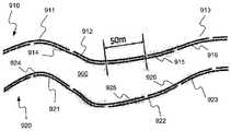
幾つかの実施形態では、非一時的コンピュータ可読媒体は、道路セグメントに沿った自律車両ナビゲーションのための疎な地図を含み得る。疎な地図は、道路セグメントに沿った自律車両の目標軌道の多項式表現と、道路セグメントに関連付けられた複数の所定の陸標とを含み得、複数の所定の陸標は、少なくとも50メートルだけ離間され得、疎な地図は、1キロメートル当たり1メガバイト以下のデータ密度を有し得る。 In some embodiments, non-transitory computer-readable media may include sparse maps for autonomous vehicle navigation along road segments. The sparse map may include a polynomial representation of the target trajectory of the autonomous vehicle along the road segment and a plurality of predetermined landmarks associated with the road segment, the plurality of predetermined landmarks separated by at least 50 meters. The sparse map may have a data density of 1 megabyte or less per kilometer.
非一時的コンピュータ可読媒体の幾つかの実施形態では、多項式表現は、三次元多項式表現であり得る。目標軌道の多項式表現は、道路セグメントに沿った車両の過去の走行の2つ以上の再構築された軌道に基づいて決定され得る。複数の所定の陸標は、50バイト以下のデータにより疎な地図に表される交通標識を含み得る。複数の所定の陸標は、50バイト以下のデータにより疎な地図に表される方向標識を含み得る。複数の所定の陸標は、100バイト以下のデータにより疎な地図に表される汎用標識を含み得る。複数の所定の陸標は、100バイト以下のデータにより疎な地図に表される略矩形の物体を含み得る。疎な地図での略矩形の物体の表現は、略矩形の物体に関連付けられた簡略画像シグネチャを含み得る。複数の所定の陸標は、陸標サイズ、前の陸標までの距離、陸標タイプ、及び陸標位置を含むパラメータにより疎な地図において表され得る。疎な地図に含まれる複数の所定の陸標は、少なくとも2キロメートルだけ離間され得る。疎な地図に含まれる複数の所定の陸標は、少なくとも1キロメートルだけ離間され得る。疎な地図に含まれる複数の所定の陸標は、少なくとも100メートルだけ離間され得る。疎な地図は、1キロメートル当たり100キロバイト以下のデータ密度を有し得る。疎な地図は、1キロメートル当たり10キロバイト以下のデータ密度を有し得る。複数の所定の陸標は、1メートル以内の長手方向位置特定精度を維持するのに十分なレートを超えるレートで疎な地図に現れ得る。 In some embodiments of the non-transitory computer-readable medium, the polynomial representation may be a three-dimensional polynomial representation. A polynomial representation of the target trajectory may be determined based on the two or more reconstructed trajectories of past travel of the vehicle along the road segment. The plurality of predetermined landmarks may include traffic signs represented on a sparse map with up to 50 bytes of data. The plurality of predetermined landmarks may include directional markers represented on a sparse map with up to 50 bytes of data. The plurality of predetermined landmarks may include a generic indicator represented on a sparse map with 100 bytes or less of data. The plurality of predetermined landmarks may include a substantially rectangular object represented on a sparse map by 100 bytes or less of data. The representation of the generally rectangular object in the sparse map may include a simplified image signature associated with the generally rectangular object. The plurality of predetermined landmarks may be represented in a sparse map by parameters including landmark size, distance to previous landmark, landmark type, and landmark position. The plurality of predetermined landmarks included in the sparse map may be separated by at least 2 kilometers. The plurality of predetermined landmarks included in the sparse map may be separated by at least 1 km. The plurality of predetermined landmarks included in the sparse map may be separated by at least 100 meters. A sparse map can have a data density of 100 kilobytes or less per kilometer. A sparse map may have a data density of 10 kilobytes or less per kilometer. Multiple predetermined landmarks may appear on a sparse map at a rate that is more than sufficient to maintain longitudinal localization accuracy within 1 meter.
幾つかの実施形態では、自律車両は、本体と、道路セグメントに沿った自律車両ナビゲーションのための疎な地図を含み得る非一時的コンピュータ可読媒体とを含み得る。疎な地図は、道路セグメントに沿った自律車両の目標軌道の多項式表現と、道路セグメントに関連付けられた複数の所定の陸標とを含み得、複数の所定の陸標は、少なくとも50メートルだけ離間され、疎な地図は、1キロメートル当たり1メガバイト以下のデータ密度を有する。自律車両は、疎な地図に含まれるデータを実行して、道路セグメントに沿った自律車両ナビゲーションを提供するように構成されるプロセッサを含み得る。 In some embodiments, an autonomous vehicle may include a body and a non-transitory computer-readable medium that may include a sparse map for autonomous vehicle navigation along road segments. The sparse map may include a polynomial representation of a target trajectory of an autonomous vehicle along a road segment and a plurality of predetermined landmarks associated with the road segment, the plurality of predetermined landmarks separated by at least 50 meters. And sparse maps have a data density of less than 1 megabyte per kilometer. The autonomous vehicle may include a processor configured to execute the data contained in the sparse map to provide autonomous vehicle navigation along road segments.
自律車両の幾つかの実施形態では、多項式表現は、三次元多項式表現であり得る。目標軌道の多項式表現は、道路セグメントに沿った車両の過去の走行の2つ以上の再構築された軌道に基づいて決定され得る。 In some embodiments of autonomous vehicles, the polynomial representation may be a three-dimensional polynomial representation. A polynomial representation of the target trajectory may be determined based on the two or more reconstructed trajectories of past travel of the vehicle along the road segment.
幾つかの実施形態では、自律車両は、本体と、疎な地図に含まれるデータを受信し、道路セグメントに沿った自律車両ナビゲーションのためにデータを実行するように構成されるプロセッサとを含み得る。疎な地図は、道路セグメントに沿った自律車両の目標軌道の多項式表現と、道路セグメントに関連付けられた複数の所定の陸標とを含み得、複数の所定の陸標は、少なくとも50メートルだけ離間され、疎な地図は、1キロメートル当たり1メガバイト以下のデータ密度を有する。 In some embodiments, an autonomous vehicle may include a body and a processor configured to receive data contained in a sparse map and execute the data for autonomous vehicle navigation along road segments. .. The sparse map may include a polynomial representation of a target trajectory of an autonomous vehicle along a road segment and a plurality of predetermined landmarks associated with the road segment, the plurality of predetermined landmarks separated by at least 50 meters. And sparse maps have a data density of less than 1 megabyte per kilometer.
幾つかの実施形態では、自律車両ナビゲーションで使用される車両ナビゲーション情報を処理する方法は、サーバにより、ナビゲーション情報を複数の車両から受信することを含み得る。複数の車両からのナビゲーション情報は、共通の道路セグメントに関連付けられ得る。本方法は、サーバにより、共通の道路セグメントに関連付けられたナビゲーション情報を記憶することを含み得る。本方法は、サーバにより、複数の車両からのナビゲーション情報に基づいて、共通の道路セグメントの自律車両道路ナビゲーションモデルの少なくとも一部を生成することと、共通の道路セグメントに沿った1つ又は複数の自律車両の自律的ナビゲーションに使用するために、サーバにより、自律車両道路ナビゲーションモデルを1つ又は複数の自律車両に配信することとを含み得る。 In some embodiments, a method of processing vehicle navigation information used in autonomous vehicle navigation can include receiving navigation information from multiple vehicles by a server. Navigation information from multiple vehicles may be associated with a common road segment. The method may include storing navigation information associated with the common road segment by the server. The method includes causing a server to generate at least a portion of an autonomous vehicle road navigation model of a common road segment based on navigation information from the plurality of vehicles, and one or more along the common road segment. Delivering an autonomous vehicle road navigation model to one or more autonomous vehicles by a server for use in autonomous navigation of the autonomous vehicle.
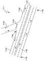
本方法の幾つかの実施形態では、ナビゲーション情報は、各車両が共通の道路セグメントにわたり走行する際の複数の車両のそれぞれからの軌道を含み得る。軌道は、三次元並進移動及び三次元回転移動を含め、カメラの検知移動に基づいて特定され得る。ナビゲーション情報は、レーン割り当てを含み得る。自律車両道路ナビゲーションモデルの少なくとも一部を生成することは、共通の道路セグメントに沿った車両軌道をクラスタ化することと、クラスタ化された車両軌道に基づいて、共通の道路セグメントに沿った目標軌道を決定することとを含み得る。自律車両道路ナビゲーションモデルは、共通の道路セグメントに沿った目標軌道に対応する三次元スプラインを含み得る。目標軌道は、共通の道路セグメントの1つのレーンに関連付けられ得る。自律車両道路ナビゲーションモデルは、複数の目標軌道を含み得、各目標軌道に、共通の道路セグメントの別個のレーンが関連付けられる。クラスタ化された車両軌道に基づいて共通の道路セグメントに沿った目標軌道を決定することは、クラスタ化された車両軌道に基づいて平均値軌道又は平均軌道を見つけることを含み得る。目標軌道は、三次元スプラインにより表され得る。スプラインは、1キロメートル当たり10キロバイト未満で定義され得る。自律車両道路ナビゲーションモデルは、少なくとも1つの陸標の位置を含む、少なくとも1つの陸標の識別情報を含み得る。少なくとも1つの陸標の位置は、複数の車両に関連付けられたセンサシステムを使用して実行される位置測定に基づいて特定され得る。位置測定の平均をとって少なくとも1つの陸標の位置を取得し得る。少なくとも1つの陸標は、交通標識、矢印マーク、レーンマーク、破線レーンマーク、信号機、停止線、方向標識、陸標ビーコン、又は街灯柱のうちの少なくとも1つを含み得る。 In some embodiments of the method, the navigation information may include trajectories from each of the vehicles as each vehicle travels over a common road segment. Trajectories can be identified based on the sensed movements of the camera, including three-dimensional translational movements and three-dimensional rotational movements. The navigation information may include lane assignments. Generating at least a portion of the autonomous vehicle road navigation model includes clustering vehicle trajectories along a common road segment and, based on the clustered vehicle trajectories, a target trajectory along a common road segment. Determining. The autonomous vehicle road navigation model may include three-dimensional splines corresponding to target trajectories along common road segments. The target trajectory may be associated with one lane of the common road segment. The autonomous vehicle road navigation model may include multiple target trajectories, with each target trajectory being associated with a separate lane of a common road segment. Determining a target trajectory along a common road segment based on the clustered vehicle trajectories may include finding an average value trajectory or an average trajectory based on the clustered vehicle trajectories. The target trajectory can be represented by a three-dimensional spline. Splines can be defined at less than 10 kilobytes per kilometer. The autonomous vehicle road navigation model may include identification information for at least one landmark, including the location of the at least one landmark. The position of the at least one landmark may be determined based on position measurements performed using sensor systems associated with multiple vehicles. The position measurements may be averaged to obtain the position of at least one landmark. The at least one landmark may include at least one of a traffic sign, an arrow mark, a lane mark, a dashed lane mark, a traffic light, a stop line, a direction sign, a landmark beacon, or a lamppost.
幾つかの実施形態では、車両のナビゲーションシステムは、少なくとも1つのプロセッサを含み得、少なくとも1つのプロセッサは、カメラから、車両に関連付けられた少なくとも1つの環境画像を受信することと、少なくとも1つの環境画像を分析して、車両に関連するナビゲーション情報を特定することと、ナビゲーション情報を車両からサーバに送信することとを行うようにプログラムされる。少なくとも1つのプロセッサは、サーバから自律車両道路ナビゲーションモデルを受信するようにプログラムされ得る。自律車両道路ナビゲーションモデルは、送信されたナビゲーション情報に基づく少なくとも1つの更新を含み得る。少なくとも1つのプロセッサは、自律車両道路ナビゲーションモデルに基づいて、車両による少なくとも1つのナビゲーション操作を生じさせるようにプログラムされ得る。 In some embodiments, a vehicle navigation system may include at least one processor, the at least one processor receiving from a camera at least one environmental image associated with the vehicle and the at least one environment. It is programmed to analyze the image to identify navigation information associated with the vehicle and to send the navigation information from the vehicle to the server. At least one processor may be programmed to receive the autonomous vehicle road navigation model from the server. The autonomous vehicle road navigation model may include at least one update based on the transmitted navigation information. The at least one processor may be programmed to cause at least one navigation operation by the vehicle based on the autonomous vehicle road navigation model.
本ナビゲーションシステムの幾つかの実施形態では、ナビゲーション情報は、各車両が共通の道路セグメントにわたり走行する際の複数の車両のそれぞれからの軌道を含み得る。 In some embodiments of the navigation system, the navigation information may include trajectories from each of the vehicles as each vehicle travels over a common road segment.
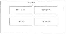
幾つかの実施形態では、自律車両ナビゲーションに使用するために車両ナビゲーション情報を処理するサーバは、複数の車両と通信するように構成される通信ユニットと、通信ユニットを介してナビゲーション情報を車両から受信するようにプログラムされる少なくとも1つのプロセッサとを含み得る。少なくとも1つのプロセッサは、ナビゲーション情報に基づいて自律車両道路ナビゲーションモデルの少なくとも一部を生成することと、自律車両道路ナビゲーションモデルの少なくとも一部を、車両のうちの少なくとも1台に送信して、自律車両道路ナビゲーションモデルの一部に基づいて車両のうちの少なくとも1台によるナビゲーション操作を生じさせることとを行うようにプログラムされ得る。 In some embodiments, a server processing vehicle navigation information for use in autonomous vehicle navigation includes a communication unit configured to communicate with a plurality of vehicles and receiving navigation information from the vehicles via the communication unit. And at least one processor programmed to do so. The at least one processor generates at least a portion of the autonomous vehicle road navigation model based on the navigation information and transmits at least a portion of the autonomous vehicle road navigation model to at least one of the vehicles for autonomous operation. Causing a navigation operation by at least one of the vehicles based on a portion of the vehicle road navigation model.
サーバの幾つかの実施形態では、ナビゲーション情報は、各車両が共通の道路セグメントにわたり走行する際の複数の車両のそれぞれからの軌道を含み得る。自律車両道路ナビゲーションモデルの一部は、自律車両道路ナビゲーションモデルに対する更新を含み得る。 In some embodiments of the server, the navigation information may include trajectories from each of the vehicles as each vehicle travels over a common road segment. Part of the autonomous vehicle road navigation model may include updates to the autonomous vehicle road navigation model.
幾つかの実施形態では、車両のナビゲーションシステムは、少なくとも1つのプロセッサを含み得、少なくとも1つのプロセッサは、1つ又は複数のセンサから、車両の動作を示す出力を受信することと、1つ又は複数のセンサからの出力に基づいて、車両の実際の軌道を特定することと、カメラから、車両に関連付けられた少なくとも1つの環境画像を受信することと、少なくとも1つの環境画像を分析して、少なくとも1つのナビゲーション制約に関連付けられた情報を特定することと、車両の実際の軌道と、少なくとも1つのナビゲーション制約に関連付けられた特定された情報に基づく実際の軌道への1つ又は複数の修正とを含む目標軌道を決定することと、目標軌道を車両からサーバに送信することとを行うようにプログラムされる。 In some embodiments, a vehicle navigation system may include at least one processor, the at least one processor receiving output from one or more sensors that is indicative of vehicle operation, and/or Determining the actual trajectory of the vehicle based on the outputs from the plurality of sensors, receiving from the camera at least one environmental image associated with the vehicle, and analyzing the at least one environmental image, Identifying information associated with the at least one navigation constraint, an actual trajectory of the vehicle, and one or more modifications to the actual trajectory based on the identified information associated with the at least one navigation constraint. Is determined and the target trajectory is transmitted from the vehicle to the server.
本システムの幾つかの実施形態では、1つ又は複数のセンサは、速度センサを含み得る。1つ又は複数のセンサは、加速度計を含み得る。1つ又は複数のセンサは、カメラを含み得る。少なくとも1つのナビゲーション制約は、障壁、物体、レーンマーク、標識、又は別の車両のうちの少なくとも1つを含み得る。カメラは、車両内に含まれ得る。 In some embodiments of the system, the one or more sensors may include velocity sensors. The one or more sensors may include accelerometers. The one or more sensors may include a camera. The at least one navigation constraint may include at least one of a barrier, an object, a lane mark, a sign, or another vehicle. The camera may be included in the vehicle.
幾つかの実施形態では、目標軌道をサーバにアップロードする方法は、1つ又は複数のセンサから、車両の動作を示す出力を受信することと、1つ又は複数のセンサからの出力に基づいて、車両の実際の軌道を特定することと、カメラから、車両に関連付けられた少なくとも1つの環境画像を受信することと、少なくとも1つの環境画像を分析して、少なくとも1つのナビゲーション制約に関連付けられた情報を特定することと、車両の実際の軌道と、少なくとも1つのナビゲーション制約に関連付けられた特定された情報に基づく実際の軌道への1つ又は複数の修正とを含む目標軌道を決定することと、目標軌道を車両からサーバに送信することとを含み得る。 In some embodiments, a method of uploading a target trajectory to a server is based on receiving output indicative of vehicle motion from one or more sensors and based on the output from the one or more sensors. Identifying the actual trajectory of the vehicle, receiving from the camera at least one environmental image associated with the vehicle, and analyzing the at least one environmental image to associate information associated with the at least one navigation constraint Determining the actual trajectory of the vehicle and one or more modifications to the actual trajectory based on the identified information associated with the at least one navigation constraint, Transmitting the target trajectory from the vehicle to the server.
本方法の幾つかの実施形態では、1つ又は複数のセンサは、速度センサを含み得る。1つ又は複数のセンサは、加速度計を含み得る。1つ又は複数のセンサは、カメラを含み得る。少なくとも1つのナビゲーション制約は、障壁、物体、レーンマーク、標識、又は別の車両のうちの少なくとも1つを含み得る。カメラは、車両内に含まれ得る。 In some embodiments of the method, the one or more sensors may include velocity sensors. The one or more sensors may include accelerometers. The one or more sensors may include a camera. The at least one navigation constraint may include at least one of a barrier, an object, a lane mark, a sign, or another vehicle. The camera may be included in the vehicle.
幾つかの実施形態では、自律車両ナビゲーションで使用される陸標を識別するシステムは、少なくとも1つのプロセッサを含み得、少なくとも1つのプロセッサは、陸標に関連付けられた少なくとも1つの識別子を受信することと、陸標を対応する道路セグメントに関連付けることと、陸標に関連付けられた少なくとも1つの識別子を含むように、対応する道路セグメントに対する自律車両道路ナビゲーションモデルを更新することと、更新された自律車両道路ナビゲーションモデルを複数の自律車両に配信することとを行うようにプログラムされる。少なくとも1つの識別子は、ホスト車両に関連付けられたカメラからの、ホスト車両の環境を表す少なくとも1つの画像の取得と、ホスト車両の環境内の陸標を識別するための少なくとも1つの画像の分析と、陸標に関連付けられた少なくとも1つの識別子を特定するための少なくとも1つの画像の分析とに基づいて特定され得る。 In some embodiments, a system for identifying landmarks used in autonomous vehicle navigation can include at least one processor, the at least one processor receiving at least one identifier associated with the landmark. And associating the landmark with the corresponding road segment, updating the autonomous vehicle road navigation model for the corresponding road segment to include at least one identifier associated with the landmark, and the updated autonomous vehicle. It is programmed to deliver the road navigation model to multiple autonomous vehicles. The at least one identifier is for obtaining at least one image of the host vehicle's environment from a camera associated with the host vehicle and analyzing the at least one image to identify landmarks in the host vehicle's environment. , At least one image analysis for identifying at least one identifier associated with the landmark.
本システムの幾つかの実施形態では、少なくとも1つの識別子は、陸標の位置を含み得る。少なくとも1つの識別子は、陸標の形状を含み得る。少なくとも1つの識別子は、陸標のサイズを含み得る。少なくとも1つの識別子は、別の陸標に対する陸標の距離を含み得る。少なくとも1つの識別子は、陸標が複数の陸標のタイプのうちの1つとして識別されることに基づいて特定され得る。陸標タイプは、交通標識を含み得る。陸標タイプは、柱を含み得る。陸標タイプは、方向インジケータを含み得る。陸標タイプは、矩形標識を含み得る。少なくとも1つの識別子は、簡略シグネチャ表現を更に含み得る。陸標の簡略シグネチャ表現は、所定のデータサイズの一連の番号への陸標の画像のマッピングに基づいて特定され得る。簡略シグネチャ表現は、陸標の外観を示し得る。簡略シグネチャ表現は、陸標の画像のカラーパターン又は画像の輝度パターンのうちの少なくとも一方を示し得る。陸標は、方向標識、交通標識、街灯柱、道路マーク、及びビジネス標識のうちの少なくとも1つを含み得る。 In some embodiments of the system, the at least one identifier may include a landmark location. The at least one identifier may include a landmark shape. The at least one identifier may include landmark size. The at least one identifier may include a landmark's distance to another landmark. The at least one identifier may be identified based on the landmark being identified as one of a plurality of landmark types. Landmark types may include traffic signs. Landmark types may include pillars. Landmark types may include direction indicators. Landmark types may include rectangular markings. The at least one identifier may further include a simplified signature expression. A simplified signature representation of landmarks may be identified based on the mapping of landmark images to a series of numbers of a given data size. The short signature representation may show the appearance of landmarks. The short signature representation may indicate at least one of a color pattern of the landmark image or a luminance pattern of the image. The landmark may include at least one of a direction sign, a traffic sign, a light pole, a road mark, and a business sign.
幾つかの実施形態では、自律車両ナビゲーションで使用される陸標を識別する方法は、陸標に関連付けられた少なくとも1つの識別子を受信することと、陸標を対応する道路セグメントに関連付けることと、陸標に関連付けられた少なくとも1つの識別子を含むように、対応する道路セグメントに対する自律車両道路ナビゲーションモデルを更新することと、更新された自律車両道路ナビゲーションモデルを複数の自律車両に配信することとを含み得る。 In some embodiments, a method of identifying a landmark used in autonomous vehicle navigation includes receiving at least one identifier associated with the landmark and associating the landmark with a corresponding road segment. Updating the autonomous vehicle road navigation model for the corresponding road segment to include at least one identifier associated with the landmark and delivering the updated autonomous vehicle road navigation model to a plurality of autonomous vehicles. May be included.
幾つかの実施形態では、本方法は、少なくとも1つの識別子を特定することを含み得る。少なくとも1つの識別子を特定することは、ホスト車両に関連付けられたカメラから、ホスト車両の環境を表す少なくとも1つの画像を取得することと、少なくとも1つの画像を分析して、ホスト車両の環境内の陸標を識別することと、少なくとも1つの画像を分析して、陸標に関連付けられた少なくとも1つの識別子を特定することとを含み得る。少なくとも1つの識別子は、別の陸標に対する陸標の距離を含み得、少なくとも1つの識別子を特定することは、別の陸標に対する陸標の距離を特定することを含み得る。少なくとも1つの識別子は、簡略シグネチャ表現を更に含み得、少なくとも1つの識別子を特定することは、少なくとも1つの画像から簡略シグネチャ表現を決定することを含む。 In some embodiments, the method can include identifying at least one identifier. Identifying the at least one identifier includes obtaining at least one image of the host vehicle's environment from a camera associated with the host vehicle, and analyzing the at least one image to identify the host vehicle's environment within the environment. It may include identifying a landmark and analyzing at least one image to identify at least one identifier associated with the landmark. The at least one identifier may include a landmark distance to another landmark, and identifying the at least one identifier may include identifying a landmark distance to another landmark. The at least one identifier may further include a short signature representation, and identifying the at least one identifier includes determining the short signature representation from the at least one image.
幾つかの実施形態では、自律車両のナビゲーションに使用される陸標の位置を特定するシステムは、少なくとも1つのプロセッサを含み得、少なくとも1つのプロセッサは、陸標の測定位置を受信することと、陸標の測定位置、及び陸標の少なくとも1つの前に取得された位置に基づいて、陸標の改良された位置を特定することとを行うようにプログラムされる。測定位置及び少なくとも1つの前に取得された位置は、ホスト車両に関連付けられたカメラからの、ホスト車両に関連付けられた少なくとも1つの環境画像の取得と、ホスト車両の環境内の陸標を識別するための少なくとも1つの環境画像の分析と、ホスト車両の位置を表す全地球測位システム(GPS)データの受信と、ホスト車両に対する識別された陸標の相対位置を特定するための少なくとも1つの環境画像の分析と、少なくともGPSデータ及び特定された相対位置に基づく陸標のグローバル位置(globally localized position)の特定とに基づいて特定され得る。 In some embodiments, a system for locating landmarks used for navigation of an autonomous vehicle can include at least one processor, the at least one processor receiving landmark measurement positions; Determining the improved position of the landmark based on the measured position of the landmark and the previously acquired position of at least one of the landmarks. The measured position and the at least one previously acquired position identify at least one environmental image associated with the host vehicle from a camera associated with the host vehicle and identify landmarks within the environment of the host vehicle. For analyzing at least one environmental image, receiving Global Positioning System (GPS) data representing the position of the host vehicle, and at least one environmental image for determining the relative position of the identified landmark to the host vehicle. And at least a globally localized position of the landmark based on the GPS data and the identified relative position.
本システムの幾つかの実施形態では、陸標は、交通標識、矢印、レーンマーク、破線レーンマーク、信号機、停止線、方向標識、陸標ビーコン、又は街灯柱のうちの少なくとも1つを含み得る。車両に対する識別された陸標の相対位置を特定するための少なくとも1つの画像の分析は、少なくとも1つの画像に関連付けられたスケールに基づいて距離を計算することを含み得る。少なくとも1つの画像を分析して、車両に対する識別された陸標の相対位置を特定することは、少なくとも1つの画像に関連付けられたオプティカルフローに基づいて距離を計算することを含み得る。GPSデータは、ホスト車両に含まれるGPSデバイスから受信され得る。カメラは、ホスト車両に含まれ得る。陸標の改良された位置を特定することは、陸標の測定位置と少なくとも1つの前に取得された位置との平均をとることを含み得る。 In some embodiments of the system, the landmark may include at least one of a traffic sign, arrow, lane mark, dashed lane mark, traffic light, stop line, directional sign, landmark beacon, or lamppost. .. Analyzing the at least one image to determine the relative position of the identified landmark with respect to the vehicle may include calculating a distance based on a scale associated with the at least one image. Analyzing the at least one image to determine the relative position of the identified landmark to the vehicle may include calculating a distance based on the optical flow associated with the at least one image. GPS data may be received from GPS devices included in the host vehicle. The camera may be included in the host vehicle. Identifying the improved position of the landmark may include averaging the measured position of the landmark and at least one previously acquired position.
幾つかの実施形態では、自律車両のナビゲーションに使用される陸標の位置を特定する方法は、陸標の測定位置を受信することと、陸標の測定位置及び陸標の少なくとも1つの前に取得された位置に基づいて、陸標の改良された位置を特定することとを含み得る。測定位置及び少なくとも1つの前に取得された位置は、ホスト車両に関連付けられたカメラからの、ホスト車両に関連付けられた少なくとも1つの環境画像の取得と、ホスト車両の環境内の陸標を識別するための少なくとも1つの環境画像の分析と、ホスト車両の位置を表す全地球測位システム(GPS)データの受信と、ホスト車両に対する識別された陸標の相対位置を特定するための少なくとも1つの環境画像の分析と、少なくともGPSデータ及び特定された相対位置に基づく陸標のグローバル位置の特定とに基づいて特定され得る。 In some embodiments, a method of locating a landmark used for navigation of an autonomous vehicle includes receiving a landmark measurement location and prior to at least one of the landmark measurement location and the landmark. Identifying an improved location of the landmark based on the obtained location. The measured position and the at least one previously acquired position identify at least one environmental image associated with the host vehicle from a camera associated with the host vehicle and identify landmarks within the environment of the host vehicle. For analyzing at least one environmental image, receiving Global Positioning System (GPS) data representing the position of the host vehicle, and at least one environmental image for determining the relative position of the identified landmark to the host vehicle. And at least a global location of the landmark based on the GPS data and the identified relative location.
本方法の幾つかの実施形態では、陸標は、交通標識、矢印、レーンマーク、破線レーンマーク、信号機、停止線、方向標識、陸標ビーコン、又は街灯柱のうちの少なくとも1つを含み得る。車両に対する識別された陸標の相対位置を特定するための少なくとも1つの画像の分析は、少なくとも1つの画像に関連付けられたスケールに基づいて距離を計算することを含み得る。車両に対する識別された陸標の相対位置を特定するための少なくとも1つの画像の分析は、少なくとも1つの画像に関連付けられたオプティカルフローに基づいて距離を計算することを含み得る。GPSデータは、ホスト車両に含まれるGPSデバイスから受信され得る。カメラは、ホスト車両に含まれ得る。陸標の改良された位置を特定することは、陸標の測定位置と少なくとも1つの前に取得された位置との平均をとることを含み得る。 In some embodiments of the method, the landmark may include at least one of a traffic sign, arrow, lane mark, dashed lane mark, traffic light, stop line, directional sign, landmark beacon, or lamppost. .. Analyzing the at least one image to determine the relative position of the identified landmark with respect to the vehicle may include calculating a distance based on a scale associated with the at least one image. Analyzing the at least one image to determine the relative position of the identified landmark with respect to the vehicle may include calculating a distance based on the optical flow associated with the at least one image. GPS data may be received from GPS devices included in the host vehicle. The camera may be included in the host vehicle. Identifying the improved position of the landmark may include averaging the measured position of the landmark and at least one previously acquired position.
幾つかの実施形態では、自律車両は、本体と、少なくとも1つのプロセッサとを含み得、少なくとも1つのプロセッサは、陸標の測定位置を受信することと、陸標の測定位置及び陸標の少なくとも1つの前に取得された位置に基づいて、陸標の改良された位置を特定することとを行うようにプログラムされる。少なくとも1つのプロセッサは、車両に関連付けられたカメラからの、車両に関連付けられた少なくとも1つの環境画像の取得と、車両の環境内の陸標を識別するための少なくとも1つの環境画像の分析と、車両の位置を表す全地球測位システム(GPS)データの受信と、車両に対する識別された陸標の相対位置を特定するための少なくとも1つの環境画像の分析と、少なくともGPSデータ及び特定された相対位置に基づく陸標のグローバル位置の特定とに基づいて、測定位置及び少なくとも1つの前に取得された位置を特定するように更にプログラムされ得る。 In some embodiments, the autonomous vehicle may include a body and at least one processor, the at least one processor receiving the landmark measurement location and at least the landmark measurement location and the landmark. Locating the improved location of the landmark based on the one previously acquired location. At least one processor obtaining at least one environmental image associated with the vehicle from a camera associated with the vehicle and analyzing the at least one environmental image to identify landmarks in the environment of the vehicle; Receiving Global Positioning System (GPS) data representing the position of the vehicle, analyzing at least one environmental image to determine the relative position of the identified landmark to the vehicle, at least GPS data and the identified relative position Based on the determination of the global position of the landmark based on the? And the at least one previously acquired position may be further programmed.
本車両の幾つかの実施形態では、陸標は、交通標識、矢印、レーンマーク、破線レーンマーク、信号機、停止線、方向標識、陸標ビーコン、又は街灯柱のうちの少なくとも1つを含み得る。車両に対する識別された陸標の相対位置を特定するための少なくとも1つの画像の分析は、少なくとも1つの画像に関連付けられたスケールに基づいて距離を計算することを含み得る。少なくとも1つの画像を分析して、車両に対する識別された陸標の相対位置を特定することは、少なくとも1つの画像に関連付けられたオプティカルフローに基づいて距離を計算することを含み得る。GPSデータは、ホスト車両に含まれるGPSデバイスから受信され得る。陸標の改良された位置を特定することは、陸標の測定位置と少なくとも1つの前に取得された位置との平均をとることを含み得る。 In some embodiments of the vehicle, the landmark may include at least one of a traffic sign, arrow, lane mark, dashed lane mark, traffic light, stop line, direction sign, landmark beacon, or lamppost. .. Analyzing the at least one image to determine the relative position of the identified landmark with respect to the vehicle may include calculating a distance based on a scale associated with the at least one image. Analyzing the at least one image to determine the relative position of the identified landmark to the vehicle may include calculating a distance based on the optical flow associated with the at least one image. GPS data may be received from GPS devices included in the host vehicle. Identifying the improved position of the landmark may include averaging the measured position of the landmark and at least one previously acquired position.
幾つかの実施形態では、道路セグメントに沿って車両を自律的にナビゲートするシステムは、少なくとも1つのプロセッサを含み得、少なくとも1つのプロセッサは、画像捕捉デバイスから、車両の環境を表す少なくとも1つの画像を受信することと、少なくとも1つの画像を分析して、少なくとも1つの認識済み陸標を識別することと、少なくとも部分的に認識済み陸標の所定の位置に基づいて、道路セグメントに関連付けられた所定の道路モデル軌道に対する車両の現在位置を特定することと、所定の道路モデル軌道に対する車両の特定された現在位置での所定の道路モデル軌道の方向に基づいて、車両の自律操舵動作を決定することとを行うようにプログラムされる。 In some embodiments, a system for autonomously navigating a vehicle along a road segment may include at least one processor, the at least one processor, from the image capture device, at least one representing an environment of the vehicle. Associated with a road segment based on receiving an image, analyzing at least one image to identify at least one recognized landmark, and based at least in part on a predetermined position of the recognized landmark. Determining the current position of the vehicle with respect to the predetermined road model trajectory, and determining the autonomous steering operation of the vehicle based on the direction of the predetermined road model trajectory at the specified current position of the vehicle with respect to the predetermined road model trajectory It is programmed to do what it does.
本システムの幾つかの実施形態では、認識済み陸標は、交通標識、矢印マーク、レーンマーク、破線レーンマーク、信号機、停止線、方向標識、反射板、陸標ビーコン、又は街灯柱のうちの少なくとも1つを含み得る。認識済み陸標は、道路セグメント上のライン間隔変更を含み得る。認識済み陸標は、ビジネスの標識を含み得る。所定の道路モデル軌道は、道路セグメントに沿った目標軌道の三次元多項式表現を含み得る。認識済み陸標間のナビゲーションは、車両速度を積分して、所定の道路モデル軌道に沿った車両の位置を特定することを含み得る。プロセッサは、車両をナビゲートする自律操舵動作に基づいて、車両の操舵システムを調整するように更にプログラムされ得る。プロセッサは、少なくとも1つの認識済み陸標からの車両の距離を特定することと、その距離に基づいて、道路セグメントに関連付けられた所定の道路モデル軌道上に車両が位置しているか否かを特定することとを行うように更にプログラムされ得る。プロセッサは、車両が所定の道路モデル軌道上に位置してない場合、車両を車両の現在位置から所定の道路モデル軌道上の位置に移動させるように、車両の操舵システムを調整するように更にプログラムされ得る。 In some embodiments of the system, the recognized landmark is one of a traffic sign, an arrow mark, a lane mark, a dashed lane mark, a traffic light, a stop line, a direction sign, a reflector, a landmark beacon, or a lamppost. It may include at least one. Recognized landmarks may include line spacing changes on road segments. Recognized landmarks may include business signs. The predetermined road model trajectory may include a three-dimensional polynomial representation of the target trajectory along the road segment. Navigation between recognized landmarks may include integrating vehicle speed to identify the vehicle's position along a given road model trajectory. The processor may be further programmed to adjust the steering system of the vehicle based on the autonomous steering action of navigating the vehicle. The processor determines a distance of the vehicle from at least one recognized landmark and, based on the distance, determines whether the vehicle is located on a predetermined road model trajectory associated with the road segment. It can be further programmed to do the following: The processor is further programmed to adjust the steering system of the vehicle to move the vehicle from the vehicle's current position to a position on the predetermined road model trajectory if the vehicle is not on the predetermined road model trajectory. Can be done.
幾つかの実施形態では、車両は、本体と、車両の環境を表す少なくとも1つの画像を取得するように構成される少なくとも1つの画像捕捉デバイスと、少なくとも1つのプロセッサとを含み得、少なくとも1つのプロセッサは、少なくとも1つの画像捕捉デバイスから、少なくとも1つの画像を受信することと、少なくとも1つの画像を分析して、少なくとも1つの認識済み陸標を識別することと、少なくとも部分的に認識済み陸標の所定の位置に基づいて、道路セグメントに関連付けられた所定の道路モデル軌道に対する車両の現在位置を特定することと、所定の道路モデル軌道に対する車両の特定された現在位置での所定の道路モデル軌道の方向に基づいて、車両の自律操舵動作を決定することとを行うようにプログラムされる。 In some embodiments, the vehicle may include a body, at least one image capture device configured to capture at least one image representative of the environment of the vehicle, and at least one processor, and at least one processor. A processor receives at least one image from at least one image capture device, analyzes the at least one image to identify at least one recognized landmark, and at least partially recognizes the recognized land. Identifying a vehicle's current position for a given road model trajectory associated with a road segment based on a given position of the sign; and a given road model at the vehicle's identified current position for a given road model trajectory Determining the autonomous steering behavior of the vehicle based on the direction of the track.
本車両の幾つかの実施形態では、認識済み陸標は、交通標識、矢印マーク、レーンマーク、破線レーンマーク、信号機、停止線、方向標識、反射板、陸標ビーコン、街灯柱、道路上の線の間隔変更、又はビジネスの標識のうちの少なくとも1つを含み得る。所定の道路モデル軌道は、道路セグメントに沿った目標軌道の三次元多項式表現を含み得る。認識済み陸標間のナビゲーションは、車両速度を積分して、所定の道路モデル軌道に沿った車両の位置を特定することを含み得る。プロセッサは、車両をナビゲートする自律操舵動作に基づいて、車両の操舵システムを調整するように更にプログラムされ得る。プロセッサは、少なくとも1つの認識済み陸標からの車両の距離を特定することと、その距離に基づいて、道路セグメントに関連付けられた所定の道路モデル軌道上に車両が位置しているか否かを特定することとを行うように更にプログラムされ得る。プロセッサは、車両が所定の道路モデル軌道上に位置してない場合、車両を車両の現在位置から所定の道路モデル軌道上の位置に移動させるように、車両の操舵システムを調整するように更にプログラムされ得る。 In some embodiments of the vehicle, the recognized landmarks are traffic signs, arrow marks, lane marks, dashed lane marks, traffic lights, stop lines, direction signs, reflectors, landmark beacons, light poles, on roads. It may include at least one of line spacing changes or business signs. The predetermined road model trajectory may include a three-dimensional polynomial representation of the target trajectory along the road segment. Navigation between recognized landmarks may include integrating vehicle speed to identify the vehicle's position along a given road model trajectory. The processor may be further programmed to adjust the steering system of the vehicle based on the autonomous steering action of navigating the vehicle. The processor determines a distance of the vehicle from at least one recognized landmark and, based on the distance, determines whether the vehicle is located on a predetermined road model trajectory associated with the road segment. It can be further programmed to do the following: The processor is further programmed to adjust the steering system of the vehicle to move the vehicle from the vehicle's current position to a position on the predetermined road model trajectory if the vehicle is not on the predetermined road model trajectory. Can be done.
幾つかの実施形態では、車両をナビゲートする方法は、車両に関連付けられた画像捕捉デバイスから、車両の環境を表す少なくとも1つの画像を受信することと、車両に関連付けられたプロセッサを使用して少なくとも1つの画像を分析して、少なくとも1つの認識済み陸標を識別することと、少なくとも部分的に認識済み陸標の所定の位置に基づいて、道路セグメントに関連付けられた所定の道路モデル軌道に対する車両の現在位置を特定することと、所定の道路モデル軌道に対する車両の特定された現在位置での所定の道路モデル軌道の方向に基づいて、車両の自律操舵動作を決定することと、車両をナビゲートする自律操舵動作に基づいて、車両の操舵システムを調整することとを含み得る。 In some embodiments, a method of navigating a vehicle uses receiving at least one image representative of the environment of the vehicle from an image capture device associated with the vehicle and using a processor associated with the vehicle. Analyzing at least one image to identify at least one recognized landmark, and for at least partially based on the predetermined position of the recognized landmark, for a given road model trajectory associated with the road segment. Determining the current position of the vehicle, determining the autonomous steering operation of the vehicle based on the direction of the predetermined road model trajectory at the specified current position of the vehicle with respect to the predetermined road model trajectory, and navigating the vehicle. Adjusting the steering system of the vehicle based on the gated autonomous steering action.
幾つかの実施形態では、本方法は、車両速度を積分することにより、所定の道路モデル軌道に沿った車両の位置を特定することを含み得る。本方法は、プロセッサを使用して、少なくとも1つの認識済み陸標からの車両の距離を特定することと、その距離に基づいて、道路セグメントに関連付けられた所定の道路モデル軌道上に車両が位置しているか否かを特定することとを含み得る。本方法は、車両を車両の現在位置から所定の道路モデル軌道上の位置に移動させるのに必要な変換を決定することと、変換に基づいて車両の操舵システムを調整することとを含み得る。 In some embodiments, the method may include locating the vehicle along a predetermined road model trajectory by integrating the vehicle speed. The method uses a processor to determine a distance of the vehicle from at least one recognized landmark and based on the distance the vehicle is positioned on a predetermined road model trajectory associated with the road segment. Identifying whether or not they are doing. The method may include determining a transformation required to move the vehicle from the vehicle's current location to a location on a predetermined road model trajectory, and adjusting the vehicle's steering system based on the transformation.
幾つかの実施形態では、道路セグメントに沿って自律車両を自律的にナビゲートするシステムは、少なくとも1つのプロセッサを含み得、少なくとも1つのプロセッサは、画像捕捉デバイスから、自律車両の環境を表す複数の画像を受信することと、少なくとも部分的に複数の画像のうちの1つ又は複数の分析に基づいて、道路セグメントに沿った自律車両の走行軌道を特定することと、複数の画像のうちの1つ又は複数の分析に基づいて、所定の道路モデル軌道に沿った自律車両の現在位置を特定することと、特定された走行軌道に基づいて、自律車両の進行方向を特定することと、走行軌道を自律車両の現在位置での所定の道路モデル軌道と比較することにより、進行方向に対する自律車両の操舵方向を決定することとを行うようにプログラムされる。 In some embodiments, a system for autonomously navigating an autonomous vehicle along a road segment may include at least one processor, wherein the at least one processor, from an image capture device, provides a plurality of representatives of the environment of the autonomous vehicle. Of the images of the plurality of images, and based at least in part on an analysis of one or more of the plurality of images, identifying a trajectory of the autonomous vehicle along the road segment; Identifying a current position of the autonomous vehicle along a predetermined road model trajectory based on one or more analyzes; identifying a traveling direction of the autonomous vehicle based on the identified travel trajectory; And determining the steering direction of the autonomous vehicle with respect to the heading by comparing the trajectory with a predetermined road model trajectory at the current position of the autonomous vehicle.
本システムの幾つかの実施形態では、走行軌道と所定の道路モデル軌道との比較は、走行軌道と所定の道路モデル軌道との誤差を低減する変換を決定することを含み得る。プロセッサは、変換に基づいて自律車両の操舵システムを調整するように更にプログラムされ得る。所定の道路モデル軌道は、道路セグメントに沿った目標軌道の三次元多項式表現を含み得る。所定の道路モデル軌道は、自律車両に含まれるメモリに記憶されるデータベースから検索され得る。所定の道路モデル軌道は、無線通信インタフェースを介して自律車両がアクセス可能なデータベースから検索され得る。画像捕捉デバイスは、自律車両に含まれ得る。操舵方向の決定は、左レーンマーク多項式モデル、右レーンマーク多項式モデル、包括的経路予測、前方車両の動作、自律車両の前の特定された自由空間、及び自律車両の前方の車両の位置に基づいて特定される仮想レーン又は仮想レーン制約のうちの1つ又は複数を含む、1つ又は複数の追加の手掛かりに更に基づき得る。操舵方向の決定は、1つ又は複数の追加の手掛かりに適用される重みに基づき得る。 In some embodiments of the system, comparing the track to the predetermined road model track may include determining a transformation that reduces the error between the track and the predetermined road model track. The processor may be further programmed to adjust the steering system of the autonomous vehicle based on the conversion. The predetermined road model trajectory may include a three-dimensional polynomial representation of the target trajectory along the road segment. The predetermined road model trajectory can be retrieved from a database stored in memory included in the autonomous vehicle. The predetermined road model trajectory can be retrieved from a database accessible to autonomous vehicles via a wireless communication interface. The image capture device may be included in an autonomous vehicle. Steering direction determination is based on left lane mark polynomial model, right lane mark polynomial model, comprehensive route prediction, forward vehicle motion, identified free space in front of the autonomous vehicle, and vehicle position in front of the autonomous vehicle. May be further based on one or more additional clues, including one or more of the virtual lanes or virtual lane constraints specified by The steering direction determination may be based on weights applied to one or more additional cues.
幾つかの実施形態では、自律車両は、本体と、自律車両の環境を表す少なくとも1つの画像を取得するように構成される少なくとも1つの画像捕捉デバイスと、少なくとも1つのプロセッサとを含み得、少なくとも1つのプロセッサは、画像捕捉デバイスから、自律車両の環境を表す複数の画像を受信することと、少なくとも部分的に複数の画像のうちの1つ又は複数の分析に基づいて、道路セグメントに沿った自律車両の走行軌道を特定することと、複数の画像のうちの1つ又は複数の分析に基づいて、所定の道路モデル軌道に沿った自律車両の現在位置を特定することと、特定された走行軌道に基づいて自律車両の進行方向を特定することと、走行軌道を自律車両の現在位置での所定の道路モデル軌道と比較することにより、進行方向に対する自律車両の操舵方向を決定することとを行うようにプログラムされる。 In some embodiments, the autonomous vehicle may include a body, at least one image capture device configured to capture at least one image representative of the environment of the autonomous vehicle, and at least one processor, at least One processor receives from the image capture device a plurality of images representing the environment of the autonomous vehicle and at least in part analyzes the one or more of the plurality of images along the road segment. Identifying the running trajectory of the autonomous vehicle, identifying the current position of the autonomous vehicle along a predetermined road model trajectory based on analysis of one or more of the plurality of images, and identifying the identified journey Specifying the traveling direction of the autonomous vehicle based on the trajectory, and determining the steering direction of the autonomous vehicle with respect to the traveling direction by comparing the traveling trajectory with a predetermined road model trajectory at the current position of the autonomous vehicle. Programmed to do.
本自律車両の幾つかの実施形態では、走行軌道と所定の道路モデル軌道との比較は、走行軌道と所定の道路モデル軌道との誤差を低減する変換を決定することを含み得る。所定の道路モデル軌道は、道路セグメントに沿った目標軌道の三次元多項式表現を含み得る。所定の道路モデル軌道は、自律車両に含まれるメモリに記憶されるデータベース及び無線通信インタフェースを介して自律車両がアクセス可能なデータベースのうちの一方から検索され得る。操舵方向の決定は、左レーンマーク多項式モデル、右レーンマーク多項式モデル、包括的経路予測、前方車両の動作、自律車両の前の特定された自由空間、及び自律車両の前方の車両の位置に基づいて特定される仮想レーン又は仮想レーン制約のうちの1つ又は複数を含む、1つ又は複数の追加の手掛かりに更に基づき得る。操舵方向の決定は、1つ又は複数の追加の手掛かりに適用される重みに基づき得る。 In some embodiments of the autonomous vehicle, comparing the track to the predetermined road model track may include determining a transformation that reduces the error between the track and the predetermined road model track. The predetermined road model trajectory may include a three-dimensional polynomial representation of the target trajectory along the road segment. The predetermined road model trajectory can be retrieved from one of a database stored in a memory included in the autonomous vehicle and a database accessible to the autonomous vehicle via a wireless communication interface. Steering direction determination is based on left lane mark polynomial model, right lane mark polynomial model, comprehensive route prediction, forward vehicle motion, identified free space in front of the autonomous vehicle, and vehicle position in front of the autonomous vehicle. May be further based on one or more additional clues, including one or more of the virtual lanes or virtual lane constraints specified by The steering direction determination may be based on weights applied to one or more additional cues.
幾つかの実施形態では、自律車両をナビゲートする方法は、画像捕捉デバイスから、自律車両の環境を表す複数の画像を受信することと、少なくとも部分的に複数の画像のうちの1つ又は複数の分析に基づいて、道路セグメントに沿った自律車両の走行軌道を特定することと、複数の画像のうちの1つ又は複数の画像の分析に基づいて、所定の道路モデル軌道に沿った自律車両の現在位置を特定することと、特定された走行軌道に基づいて自律車両の進行方向を特定することと、走行軌道を自律車両の現在位置での所定の道路モデル軌道と比較することにより、進行方向に対する自律車両の操舵方向を決定することとを含み得る。 In some embodiments, a method of navigating an autonomous vehicle comprises receiving from an image capture device a plurality of images representative of an environment of the autonomous vehicle and at least partially one or more of the plurality of images. Of the autonomous vehicle along the road segment based on the analysis of the, and based on the analysis of one or more of the plurality of images, the autonomous vehicle along the predetermined road model trajectory. The current position of the autonomous vehicle is identified, the traveling direction of the autonomous vehicle is specified based on the identified traveling trajectory, and the traveling trajectory is compared with a predetermined road model trajectory at the current position of the autonomous vehicle. Determining a steering direction of the autonomous vehicle with respect to the direction.
本方法の幾つかの実施形態では、走行軌道と所定の道路モデル軌道との比較は、走行軌道と所定の道路モデル軌道との誤差を低減する変換を決定することを含み得る。操舵方向の決定は、左レーンマーク多項式モデル、右レーンマーク多項式モデル、包括的経路予測、前方車両の動作、自律車両の前の特定された自由空間、及び自律車両の前方の車両の位置に基づいて特定される仮想レーン又は仮想レーン制約のうちの1つ又は複数を含め、1つ又は複数の追加の手掛かりに更に基づき得る。操舵方向の決定は、1つ又は複数の追加の手掛かりに適用される重みに基づき得る。 In some embodiments of the method, comparing the track to the predetermined road model track may include determining a transformation that reduces an error between the track and the predetermined road model track. Steering direction determination is based on left lane mark polynomial model, right lane mark polynomial model, comprehensive route prediction, forward vehicle motion, identified free space in front of the autonomous vehicle, and vehicle position in front of the autonomous vehicle. May be further based on one or more additional clues, including one or more of the virtual lanes or virtual lane constraints specified by The steering direction determination may be based on weights applied to one or more additional cues.
幾つかの実施形態では、交差点を通して車両を自律的にナビゲートするシステムは、少なくとも1つのプロセッサを含み得、少なくとも1つのプロセッサは、画像捕捉デバイスから、車両の環境を表す少なくとも1つの画像を受信することと、少なくとも1つの画像を分析して、車両の環境内にある2つ以上の陸標を識別することと、2つ以上の陸標のそれぞれについて、車両に対する方向インジケータを特定することと、2つ以上の陸標の方向インジケータの交点に基づいて、交差点に対する車両の現在位置を特定することと、2つ以上の陸標の方向インジケータに基づいて、車両の進行方位を特定することと、車両の進行方位を車両の現在位置での所定の道路モデル軌道と比較することにより、車両の操舵角を決定することとを行うようにプログラムされる。 In some embodiments, a system for autonomously navigating a vehicle through an intersection may include at least one processor, the at least one processor receiving at least one image representative of the environment of the vehicle from an image capture device. And analyzing at least one image to identify two or more landmarks within the vehicle's environment, and for each of the two or more landmarks, identifying a direction indicator for the vehicle. Determining the current position of the vehicle with respect to the intersection based on the intersection of the direction indicators of the two or more landmarks, and determining the heading of the vehicle based on the direction indicators of the two or more landmarks. , Determining the steering angle of the vehicle by comparing the heading of the vehicle with a predetermined road model trajectory at the vehicle's current position.
本システムの幾つかの実施形態では、所定の道路モデル軌道は、道路セグメントに沿った目標軌道の三次元多項式表現を含み得る。2つ以上の陸標は、3つ以上の陸標を含み得る。少なくとも1つのプロセッサは、操舵角を指定する制御信号を車両の操舵システムに送信するように更にプログラムされ得る。プロセッサは、車両に含まれるメモリに記憶されるデータベースから、所定の道路モデル軌道を検索するように構成され得る。プロセッサは、無線通信インタフェースを介して車両がアクセス可能なデータベースから、所定の道路モデル軌道を検索するように構成され得る。カメラは、車両に含まれ得る。プロセッサは、2つ以上の陸標の方向インジケータの交点に基づいて、交差点に対する車両の以前の位置を特定し、以前の位置及び現在位置に基づいて進行方位を特定することにより、車両の進行方位を特定するように更にプログラムされ得る。 In some embodiments of the system, the predetermined road model trajectory may include a three-dimensional polynomial representation of the target trajectory along the road segment. The two or more landmarks may include three or more landmarks. The at least one processor may be further programmed to send a control signal specifying a steering angle to a vehicle steering system. The processor may be configured to retrieve a predetermined road model trajectory from a database stored in memory included in the vehicle. The processor may be configured to retrieve the predetermined road model trajectory from a database accessible to the vehicle via the wireless communication interface. The camera may be included in the vehicle. The processor determines the vehicle's heading by determining the vehicle's previous position relative to the intersection based on the intersection of the direction indicators of the two or more landmarks, and by determining the heading based on the previous position and the current position. Can be further programmed to specify
幾つかの実施形態では、自律車両は、本体と、車両の環境を表す少なくとも1つの画像を取得するように構成される少なくとも1つの画像捕捉デバイスと、少なくとも1つのプロセッサとを含み得、少なくとも1つのプロセッサは、カメラから、車両の環境を表す少なくとも1つの画像を受信することと、少なくとも1つの画像を分析して、車両の環境内にある2つ以上の陸標を識別することと、2つ以上の陸標のそれぞれについて、車両に対する方向インジケータを特定することと、2つ以上の陸標の方向インジケータの交点に基づいて、交差点に対する車両の現在位置を特定することと、2つ以上の陸標の方向インジケータに基づいて、車両の進行方位を特定することと、車両進行方位を車両の現在位置での所定の道路モデル軌道と比較することにより、車両の操舵角を決定することとを行うようにプログラムされる。 In some embodiments, the autonomous vehicle may include a body, at least one image capture device configured to acquire at least one image representative of the environment of the vehicle, and at least one processor, at least one One processor receives from the camera at least one image representative of the environment of the vehicle; analyzes the at least one image to identify two or more landmarks within the environment of the vehicle; Identifying a directional indicator for the vehicle for each of the one or more landmarks, identifying the current position of the vehicle for the intersection based on the intersection of the directional indicators of the two or more landmarks, and Identifying the heading of the vehicle based on the direction indicator of the landmark and determining the steering angle of the vehicle by comparing the heading of the vehicle with a predetermined road model trajectory at the current position of the vehicle. Programmed to do.
本車両の幾つかの実施形態では、所定の道路モデル軌道は、道路セグメントに沿った目標軌道の三次元多項式表現を含み得る。2つ以上の陸標は、3つ以上の陸標を含み得る。少なくとも1つのプロセッサは、操舵角を指定する制御信号を車両の操舵システムに送信するように更にプログラムされ得る。所定の道路モデル軌道は、車両に含まれるメモリに記憶されるデータベース及び無線通信インタフェースを介して車両がアクセス可能なデータベースのうちの一方から検索され得る。プロセッサは、2つ以上の陸標の方向インジケータの交点に基づいて、交差点に対する車両の以前の位置を特定し、以前の位置及び現在位置に基づいて進行方位を特定することにより、車両の進行方位を特定するように更にプログラムされ得る。 In some embodiments of the vehicle, the predetermined road model trajectory may include a three-dimensional polynomial representation of the target trajectory along the road segment. The two or more landmarks may include three or more landmarks. The at least one processor may be further programmed to send a control signal specifying a steering angle to a vehicle steering system. The predetermined road model trajectory can be retrieved from one of a database stored in a memory included in the vehicle and a database accessible to the vehicle via a wireless communication interface. The processor determines the vehicle's heading by determining the vehicle's previous position relative to the intersection based on the intersection of the direction indicators of the two or more landmarks, and by determining the heading based on the previous position and the current position. Can be further programmed to specify
幾つかの実施形態では、自律車両をナビゲートする方法は、画像捕捉デバイスから、車両の環境を表す少なくとも1つの画像を受信することと、少なくとも1つのプロセッサを使用して少なくとも1つの画像を分析して、車両の環境内にある2つ以上の陸標を識別することと、2つ以上の陸標のそれぞれについて、車両に対する方向インジケータを特定することと、2つ以上の陸標の方向インジケータの交点に基づいて、交差点に対する車両の現在位置を特定することと、2つ以上の陸標の方向インジケータに基づいて、車両の進行方位を特定することと、車両進行方位を車両の現在位置での所定の道路モデル軌道と比較することにより、車両の操舵角を決定することとを含み得る。 In some embodiments, a method of navigating an autonomous vehicle includes receiving at least one image representing an environment of the vehicle from an image capture device and analyzing the at least one image using at least one processor. And identifying two or more landmarks in the environment of the vehicle, identifying a directional indicator for the vehicle for each of the two or more landmarks, and a directional indicator for the two or more landmarks. The current position of the vehicle with respect to the intersection based on the intersection of, and the heading of the vehicle based on the direction indicators of two or more landmarks; Determining the steering angle of the vehicle by comparing with a predetermined road model trajectory of
本方法の幾つかの実施形態では、所定の道路モデル軌道は、道路セグメントに沿った目標軌道の三次元多項式表現を含み得る。本方法は、車両に含まれるメモリに記憶されるデータベース及び無線通信インタフェースを介して車両がアクセス可能なデータベースのうちの一方から、所定の道路モデル軌道を検索することを含み得る。本方法は、操舵角を指定する制御信号を車両の操舵システムに送信することを含み得る。車両の進行方位を特定することは、2つ以上の陸標の方向インジケータの交点に基づいて、交差点に対する車両の以前の位置を特定することと、以前の位置及び現在位置に基づいて進行方位を特定することとを含み得る。 In some embodiments of the method, the predetermined road model trajectory may include a three-dimensional polynomial representation of the target trajectory along the road segment. The method may include retrieving a predetermined road model trajectory from one of a database stored in memory included in the vehicle and a database accessible to the vehicle via a wireless communication interface. The method may include transmitting a control signal specifying a steering angle to a vehicle steering system. Identifying the heading of the vehicle is based on the intersection of the direction indicators of two or more landmarks to identify the previous position of the vehicle with respect to the intersection, and on the basis of the previous position and the current position the heading. Identifying.
幾つかの実施形態では、複数の重複ナビゲーションマップに基づいて車両を自律的にナビゲートするシステムは、少なくとも1つのプロセッサを含み得、少なくとも1つのプロセッサは、車両を自律的に制御するのに使用される第1のナビゲーションマップを受信することであって、第1のナビゲーションマップは第1の道路セグメントに関連付けられる、受信することと、第1のナビゲーションマップの分析に基づいて、第1の道路セグメントに沿った車両の第1の自律ナビゲーション応答を決定することと、車両を自律的に制御するのに使用される第2のナビゲーションマップを受信することであって、第2のナビゲーションマップは第2の道路セグメントに関連付けられ、第1の道路セグメントは第2の道路セグメントと異なり、第1の道路セグメント及び第2の道路セグメントは重複セグメントにおいて互いに重複する、受信することと、第2のナビゲーションマップの分析に基づいて、第2の道路セグメントに沿った車両の少なくとも第2の自律ナビゲーション応答を決定することと、第1のナビゲーションマップ及び第2のナビゲーションマップのうちの少なくとも一方に基づいて、重複セグメント内の車両の少なくとも第3の自律ナビゲーション応答を決定することとを行うようにプログラムされる。 In some embodiments, a system for autonomously navigating a vehicle based on multiple overlapping navigation maps may include at least one processor, the at least one processor used to autonomously control the vehicle. Receiving a first navigation map, the first navigation map being associated with a first road segment, the first road map being based on the receiving and the analysis of the first road map. Determining a first autonomous navigation response of the vehicle along the segment and receiving a second navigation map used to autonomously control the vehicle, the second navigation map being a first navigation map. Associated with two road segments, the first road segment is different from the second road segment, the first road segment and the second road segment overlap each other in the overlapping segment, receiving and the second navigation Determining at least a second autonomous navigation response of the vehicle along the second road segment based on an analysis of the map, and based on at least one of the first navigation map and the second navigation map, Determining at least a third autonomous navigation response of the vehicles in the overlapping segment.
本システムの幾つかの実施形態では、複数の重複ナビゲーションマップのそれぞれは、それ自体の座標系を有し得る。複数の重複ナビゲーションマップは、それぞれ道路セグメントに沿った目標軌道の多項式表現を含み得る。各重複ナビゲーションマップは、1キロメートル当たり10キロバイト以下のデータ密度を有する疎な地図であり得る。重複セグメントは、少なくとも50メートルの長さを有し得る。重複セグメントは、少なくとも100メートルの長さを有し得る。少なくとも1つのプロセッサは、第1のナビゲーションマップ及び第2のナビゲーションマップの両方に基づいて、第3の自律ナビゲーション応答を決定するようにプログラムされ得る。第3の自律ナビゲーション応答は、第1の自律ナビゲーション応答と第2の自律ナビゲーション応答との組合せであり得る。第3の自律ナビゲーション応答は、第1の自律ナビゲーション応答と第2の自律ナビゲーション応答との平均であり得る。プロセッサは、第1の自律ナビゲーション応答と第2の自律ナビゲーション応答との誤差を特定することと、誤差が閾値誤差未満である場合、第2の自律ナビゲーション応答に基づいて第3の自律ナビゲーション応答を決定することとを行うように更にプログラムされ得る。 In some embodiments of the system, each of the multiple overlapping navigation maps may have its own coordinate system. The multiple overlapping navigation maps may each include a polynomial representation of a target trajectory along a road segment. Each overlapping navigation map can be a sparse map with a data density of 10 kilobytes or less per kilometer. The overlapping segment may have a length of at least 50 meters. The overlapping segment may have a length of at least 100 meters. At least one processor may be programmed to determine a third autonomous navigation response based on both the first navigation map and the second navigation map. The third autonomous navigation response may be a combination of the first autonomous navigation response and the second autonomous navigation response. The third autonomous navigation response may be an average of the first autonomous navigation response and the second autonomous navigation response. The processor identifies an error between the first autonomous navigation response and the second autonomous navigation response, and, if the error is less than a threshold error, a third autonomous navigation response based on the second autonomous navigation response. It can be further programmed to perform the determining.
幾つかの実施形態では、自律車両は、本体と、車両の環境を表す少なくとも1つの画像を取得するように構成される少なくとも1つの画像捕捉デバイスと、少なくとも1つのプロセッサとを含み得、少なくとも1つのプロセッサは、少なくとも1つの画像に基づいて、車両の現在位置を特定することと、第1の道路セグメントに関連付けられた第1のナビゲーションマップを受信することと、車両の現在位置が第1のナビゲーションマップにある場合、第1のナビゲーションマップの分析に基づいて、車両の少なくとも第1の自律ナビゲーション応答を決定することと、第2の道路セグメントと異なる第2の道路セグメントに関連付けられた第2のナビゲーションマップを受信することであって、第1の道路セグメント及び第2の道路セグメントは重複セグメントにおいて互いに重複する、受信することと、車両の現在位置が第2のナビゲーションマップにある場合、第2のナビゲーションマップの分析に基づいて、車両の少なくとも第2の自律ナビゲーション応答を決定することと、車両の現在位置が重複セグメントにある場合、第1のナビゲーションマップ及び第2のナビゲーションマップのうちの少なくとも一方に基づいて、車両の少なくとも第3の自律ナビゲーション応答を決定することとを行うようにプログラムされる。 In some embodiments, the autonomous vehicle may include a body, at least one image capture device configured to acquire at least one image representative of the environment of the vehicle, and at least one processor, at least one One processor for determining a current position of the vehicle based on the at least one image; receiving a first navigation map associated with the first road segment; Determining at least a first autonomous navigation response of the vehicle based on an analysis of the first navigation map, if present in the navigation map, and determining a second road segment associated with a second road segment different from the second road segment. Receiving the navigation map of the first road segment and the second road segment overlap each other in the overlapping segment, receiving and the current position of the vehicle is in the second navigation map. Determining at least a second autonomous navigation response of the vehicle based on an analysis of the two navigation maps, and if the current location of the vehicle is in the overlapping segment, the first navigation map and the second navigation map Determining at least a third autonomous navigation response of the vehicle based on the at least one.
本自律車両の幾つかの実施形態では、第1のナビゲーションマップ及び第2のナビゲーションマップのそれぞれは、それ自体の座標系を有し得る。第1のナビゲーションマップ及び第2のナビゲーションマップのそれぞれは、道路セグメントに沿った目標軌道の多項式表現を含み得る。少なくとも1つのプロセッサは、第1のナビゲーションマップ及び第2のナビゲーションマップの両方に基づいて、第3の自律ナビゲーション応答を決定するようにプログラムされ得る。第3の自律ナビゲーション応答は、第1の自律ナビゲーション応答と第2の自律ナビゲーション応答との組合せであり得る。プロセッサは、第1の自律ナビゲーション応答と第2の自律ナビゲーション応答との誤差を特定することと、誤差が閾値誤差未満である場合、第2の自律ナビゲーション応答に基づいて第3の自律ナビゲーション応答を決定することとを行うように更にプログラムされ得る。 In some embodiments of the autonomous vehicle, each of the first navigation map and the second navigation map may have its own coordinate system. Each of the first navigation map and the second navigation map may include a polynomial representation of a target trajectory along a road segment. At least one processor may be programmed to determine a third autonomous navigation response based on both the first navigation map and the second navigation map. The third autonomous navigation response may be a combination of the first autonomous navigation response and the second autonomous navigation response. The processor identifies an error between the first autonomous navigation response and the second autonomous navigation response, and, if the error is less than a threshold error, a third autonomous navigation response based on the second autonomous navigation response. It can be further programmed to perform the determining.
幾つかの実施形態では、自律車両をナビゲートする方法は、画像捕捉デバイスから、車両の環境を表す少なくとも1つの画像を受信することと、車両に関連付けられたプロセッサを使用して、少なくとも1つの画像に基づいて車両の現在位置を特定することと、第1の道路セグメントに関連付けられた第1のナビゲーションマップを受信することと、車両の現在位置が第1のナビゲーションマップにある場合、第1のナビゲーションマップの分析に基づいて、車両の少なくとも第1の自律ナビゲーション応答を決定することと、第2の道路セグメントと異なる第2の道路セグメントに関連付けられた第2のナビゲーションマップを受信することであって、第1の道路セグメント及び第2の道路セグメントは重複セグメントにおいて互いに重複する、受信することと、車両の現在位置が第2のナビゲーションマップにある場合、第2のナビゲーションマップの分析に基づいて、車両の少なくとも第2の自律ナビゲーション応答を決定することと、車両の現在位置が重複セグメントにある場合、第1のナビゲーションマップ及び第2のナビゲーションマップのうちの少なくとも一方に基づいて、車両の少なくとも第3の自律ナビゲーション応答を決定することとを含み得る。 In some embodiments, a method of navigating an autonomous vehicle comprises receiving from an image capture device at least one image representative of the environment of the vehicle and using a processor associated with the vehicle. Determining a current location of the vehicle based on the image, receiving a first navigation map associated with the first road segment, and determining if the current location of the vehicle is in the first navigation map Determining at least a first autonomous navigation response of the vehicle, and receiving a second navigation map associated with a second road segment different from the second road segment, based on the analysis of the navigation map of And the first road segment and the second road segment overlap each other in the overlapping segment, receiving and based on an analysis of the second navigation map if the current position of the vehicle is in the second navigation map. Determining at least a second autonomous navigation response of the vehicle, and based on at least one of the first navigation map and the second navigation map if the current location of the vehicle is in the overlapping segment. Determining at least a third autonomous navigation response.
本方法の幾つかの実施形態では、複数の重複するナビゲーションマップのそれぞれは、それ自体の座標系を有し得、複数の重複するナビゲーションマップのそれぞれは、道路セグメントに沿った目標軌道の多項式表現を含み得る。第3の自律ナビゲーション応答を決定することは、第1の自律ナビゲーション応答と第2の自律ナビゲーション応答との組合せを特定することを含み得る。本方法は、第1の自律ナビゲーション応答と第2の自律ナビゲーション応答との誤差を特定することと、誤差が閾値誤差未満である場合、第2の自律ナビゲーション応答に基づいて第3の自律ナビゲーション応答を決定することとを含み得る。 In some embodiments of the method, each of the plurality of overlapping navigation maps may have its own coordinate system, and each of the plurality of overlapping navigation maps includes a polynomial representation of a target trajectory along a road segment. Can be included. Determining the third autonomous navigation response may include identifying a combination of the first autonomous navigation response and the second autonomous navigation response. The method identifies an error between the first autonomous navigation response and the second autonomous navigation response and, if the error is less than a threshold error, a third autonomous navigation response based on the second autonomous navigation response. Determining.
幾つかの実施形態では、道路セグメントに沿った車両の疎な地図による自律ナビゲーションのシステムは、少なくとも1つのプロセッサを含み得、少なくとも1つのプロセッサは、道路セグメントの疎な地図を受信することであって、疎な地図は、1キロメートル当たり1メガバイト以下のデータ密度を有する、受信することと、カメラから、車両の環境を表す少なくとも1つの画像を受信することと、疎な地図及びカメラから受信される少なくとも1つの画像を分析することと、疎な地図及びカメラから受信される少なくとも1つの画像の分析だけに基づいて、車両の自律ナビゲーション応答を決定することとを行うようにプログラムされ得る。 In some embodiments, a system of sparse map autonomous navigation of vehicles along a road segment may include at least one processor, the at least one processor receiving a sparse map of the road segment. Thus, the sparse map has a data density of less than 1 megabyte per kilometer, receiving, receiving from the camera at least one image representing the environment of the vehicle, and receiving from the sparse map and the camera. Can be programmed to determine an autonomous navigation response of the vehicle based solely on the sparse map and analysis of the at least one image received from the camera.
本システムの幾つかの実施形態では、疎な地図は、道路セグメントに沿った目標軌道の多項式表現を含み得る。疎な地図は、1つ又は複数の認識済み陸標を含み得る。認識済み陸標は、1キロメートル当たり0.5以下のレートで疎な地図において離間され得る。認識済み陸標は、1キロメートル当たり1以下のレートで疎な地図において離間され得る。認識済み陸標は、100メートル当たり1以下のレートで疎な地図において離間され得る。疎な地図は、1キロメートル当たり100キロバイト以下のデータ密度を有し得る。疎な地図は、1キロメートル当たり10キロバイト以下のデータ密度を有し得る。 In some embodiments of the system, the sparse map may include a polynomial representation of the target trajectory along the road segment. The sparse map may include one or more recognized landmarks. Recognized landmarks can be spaced in sparse maps at a rate of 0.5 or less per kilometer. Recognized landmarks can be spaced in a sparse map at a rate of 1 or less per kilometer. Recognized landmarks can be spaced in sparse maps at a rate of 1 or less per 100 meters. A sparse map can have a data density of 100 kilobytes or less per kilometer. A sparse map may have a data density of 10 kilobytes or less per kilometer.
幾つかの実施形態では、道路セグメントに沿った車両の疎な地図による自律ナビゲーションの方法は、道路セグメントの疎な地図を受信することであって、疎な地図は、1キロメートル当たり1メガバイト以下のデータ密度を有する、受信することと、カメラから、車両の環境を表す少なくとも1つの画像を受信することと、疎な地図及びカメラから受信される少なくとも1つの画像を分析することと、疎な地図及びカメラから受信される少なくとも1つの画像の分析だけに基づいて、車両の自律ナビゲーション応答を決定することとを含み得る。 In some embodiments, a method of sparse map autonomous navigation of vehicles along a road segment is to receive a sparse map of a road segment, the sparse map being less than 1 megabyte per kilometer. Receiving with data density, receiving from the camera at least one image representing the environment of the vehicle, analyzing the sparse map and at least one image received from the camera, and the sparse map And determining the autonomous navigation response of the vehicle based solely on the analysis of the at least one image received from the camera.
本方法の幾つかの実施形態では、疎な地図は、道路セグメントに沿った目標軌道の多項式表現を含み得る。疎な地図は、1つ又は複数の認識済み陸標を含み得る。認識済み陸標は、1キロメートル当たり0.5以下のレートで疎な地図において離間され得る。認識済み陸標は、1キロメートル当たり1以下のレートで疎な地図において離間され得る。認識済み陸標は、100メートル当たり1以下のレートで疎な地図において離間され得る。疎な地図は、1キロメートル当たり100キロバイト以下のデータ密度を有し得る。疎な地図は、1キロメートル当たり10キロバイト以下のデータ密度を有し得る。 In some embodiments of the method, the sparse map may include a polynomial representation of the target trajectory along the road segment. The sparse map may include one or more recognized landmarks. Recognized landmarks can be spaced in sparse maps at a rate of 0.5 or less per kilometer. Recognized landmarks can be spaced in a sparse map at a rate of 1 or less per kilometer. Recognized landmarks can be spaced in sparse maps at a rate of 1 or less per 100 meters. A sparse map can have a data density of 100 kilobytes or less per kilometer. A sparse map may have a data density of 10 kilobytes or less per kilometer.
幾つかの実施形態では、非一時的コンピュータ可読媒体は、道路セグメントの疎な地図を受信することを含み得る、道路セグメントに沿った車両の疎な地図による自律ナビゲーションを少なくとも1つのプロセッサに実行させる命令を記憶し得る。命令は、プロセッサに、道路セグメントの疎な地図を受信するステップであって、疎な地図は、1キロメートル当たり1メガバイト以下のデータ密度を有する、ステップと、カメラから、車両の環境を表す少なくとも1つの画像を受信するステップと、疎な地図及びカメラからの少なくとも1つの画像を分析するステップと、疎な地図及びカメラから受信される少なくとも1つの画像の分析だけに基づいて、車両の自律ナビゲーション応答を決定するステップとを実行させ得る。 In some embodiments, the non-transitory computer-readable medium causes at least one processor to perform sparse map autonomous navigation of vehicles along a road segment, which may include receiving a sparse map of the road segment. The instructions may be stored. The instructions are for receiving to the processor a sparse map of a road segment, the sparse map having a data density of less than or equal to 1 megabyte per kilometer, and from the camera, at least 1 representing a vehicle environment. Vehicle autonomous navigation response based solely on receiving one image, analyzing at least one image from the sparse map and camera, and analyzing at least one image received from the sparse map and camera And the step of determining
非一時的コンピュータ可読媒体の幾つかの実施形態では、疎な地図は、道路セグメントに沿った目標軌道の多項式表現を含み得る。疎な地図は、1つ又は複数の認識済み陸標を含み得る。認識済み陸標は、1キロメートル当たり0.5以下のレートで疎な地図において離間され得る。 In some embodiments of the non-transitory computer-readable medium, the sparse map may include a polynomial representation of the target trajectory along the road segment. The sparse map may include one or more recognized landmarks. Recognized landmarks can be spaced in sparse maps at a rate of 0.5 or less per kilometer.
幾つかの実施形態では、所定の陸標位置に基づいて道路セグメントに沿って車両を自律的にナビゲートするシステムは、少なくとも1つのプロセッサを含み得、少なくとも1つのプロセッサは、カメラから、車両の環境を表す少なくとも1つの画像を受信することと、少なくとも部分的に少なくとも1つの画像に関連付けられた情報に基づいて、道路セグメントに関連付けられた所定の道路モデル軌道に沿った車両の位置を特定することと、特定された位置に基づいて、車両の前方の認識済み陸標を識別することであって、認識済み陸標はカメラの視野範囲(sight range)を超える、識別することと、車両の特定された位置を認識済み陸標の所定の位置と比較することにより、車両と認識済み陸標との間の現在距離を特定することと、特定された現在距離に基づいて、車両の自律ナビゲーション応答を決定することとを行うようにプログラムされる。 In some embodiments, a system for autonomously navigating a vehicle along a road segment based on a predetermined landmark position may include at least one processor, the at least one processor from the camera to detect the vehicle. Locating the vehicle along a predetermined road model trajectory associated with the road segment based on receiving at least one image representing the environment and at least in part based on information associated with the at least one image Identifying a recognized landmark in front of the vehicle based on the identified position, the recognized landmark exceeding the sight range of the camera and identifying the vehicle. Identifying the current distance between the vehicle and the recognized landmark by comparing the identified position with the predetermined position of the recognized landmark, and autonomous navigation of the vehicle based on the identified current distance. Is programmed to determine the response.
本システムの幾つかの実施形態では、認識済み陸標の所定の位置は、認識済み陸標に関連付けられた取得される複数の位置測定値の平均として特定され得、取得される複数の位置測定値は、少なくとも1つの環境画像の取得と、環境内の認識済み陸標を識別するための少なくとも1つの環境画像の分析と、全地球測位システム(GPS)データの受信と、車両に対する認識済み陸標の相対位置を特定するための少なくとも1つの環境画像の分析と、少なくともGPSデータ及び特定される相対位置に基づく、認識済み陸標のグローバル位置の特定とに基づいて特定され得る。自律ナビゲーション応答は、車両に関連付けられたブレーキの適用を含み得る。自律ナビゲーション応答は、車両の操舵角を変更することを含み得る。認識済み陸標は、停止線、信号機、停止標識、又は道路セグメントに沿ったカーブを含み得る。カメラは、車両に含まれ得る。 In some embodiments of the system, the predetermined position of the recognized landmark may be identified as an average of the plurality of acquired position measurements associated with the recognized landmark, and the plurality of acquired position measurements The values are: acquisition of at least one environmental image, analysis of at least one environmental image to identify recognized landmarks in the environment, reception of Global Positioning System (GPS) data, and recognition of recognized land to the vehicle. It may be determined based on an analysis of the at least one environmental image to determine the relative position of the landmark and a global location of the recognized landmark based at least on the GPS data and the identified relative position. The autonomous navigation response may include the application of brakes associated with the vehicle. The autonomous navigation response may include changing the steering angle of the vehicle. Recognized landmarks may include stop lines, traffic lights, stop signs, or curves along road segments. The camera may be included in the vehicle.
幾つかの実施形態では、所定の陸標位置に基づいて道路セグメントに沿って車両を自律的にナビゲートする方法は、カメラから、車両の環境を表す少なくとも1つの画像を受信することと、少なくとも部分的に少なくとも1つの画像に関連付けられた情報に基づいて、道路セグメントに関連付けられた所定の道路モデル軌道に沿った車両の位置を特定することと、特定された位置に基づいて、車両の前方の認識済み陸標を識別することであって、認識済み陸標はカメラの視野範囲を超える、識別することと、車両の特定された位置を認識済み陸標の所定の位置と比較することにより、車両と認識済み陸標との間の現在距離を特定することと、特定された現在距離に基づいて、車両の自律ナビゲーション応答を決定することとを含み得る。 In some embodiments, a method of autonomously navigating a vehicle along a road segment based on a predetermined landmark position includes receiving from a camera at least one image representative of the environment of the vehicle; Locating the vehicle along a predetermined road model trajectory associated with the road segment based in part on information associated with at least one image, and based on the identified location, in front of the vehicle. Identifying the recognized landmarks of the recognized landmarks beyond the range of view of the camera, and by comparing the identified position of the vehicle with the predetermined position of the recognized landmarks. , Determining a current distance between the vehicle and a recognized landmark and determining an autonomous navigation response of the vehicle based on the determined current distance.
本方法の幾つかの実施形態では、認識済み陸標の所定の位置は、認識済み陸標に関連付けられた取得される複数の位置測定値の平均として特定され得、取得される複数の位置測定値は、少なくとも1つの環境画像の取得と、環境内の認識済み陸標を識別するための少なくとも1つの環境画像の分析と、全地球測位システム(GPS)データの受信と、車両に対する認識済み陸標の相対位置を特定するための少なくとも1つの環境画像の分析と、少なくともGPSデータ及び特定される相対位置に基づく、認識済み陸標のグローバル位置の特定とに基づいて特定され得る。自律ナビゲーション応答は、車両に関連付けられたブレーキの適用を含み得る。自律ナビゲーション応答は、車両の操舵角を変更することを含み得る。認識済み陸標は、停止線、信号機、停止標識、又は道路セグメントに沿ったカーブを含み得る。カメラは、車両に含まれ得る。 In some embodiments of the method, the predetermined position of the recognized landmark may be identified as an average of the plurality of acquired position measurements associated with the recognized landmark, and the plurality of acquired position measurements The values are: acquisition of at least one environmental image, analysis of at least one environmental image to identify recognized landmarks in the environment, reception of Global Positioning System (GPS) data, and recognition of recognized land to the vehicle. It may be determined based on an analysis of the at least one environmental image to determine the relative position of the landmarks and a global location of the recognized landmarks based at least on the GPS data and the identified relative positions. The autonomous navigation response may include the application of brakes associated with the vehicle. The autonomous navigation response may include changing the steering angle of the vehicle. Recognized landmarks may include stop lines, traffic lights, stop signs, or curves along road segments. The camera may be included in the vehicle.
幾つかの実施形態では、非一時的コンピュータ可読媒体は、道路セグメントに沿った車両の自律的ナビゲーションを少なくとも1つのプロセッサに実行させる命令を記憶し得る。命令は、プロセッサに、カメラから、車両の環境を表す少なくとも1つの画像を受信することと、少なくとも部分的に少なくとも1つの画像に関連付けられた情報に基づいて、道路セグメントに関連付けられた所定の道路モデル軌道に沿った車両の位置を特定することと、特定された位置に基づいて、車両の前方の認識済み陸標を識別することであって、認識済み陸標はカメラの視野範囲を超える、識別することと、車両の特定された位置を認識済み陸標の所定の位置と比較することにより、車両と認識済み陸標との間の現在距離を特定することと、特定された現在距離に基づいて、車両の自律ナビゲーション応答を決定することとを実行させ得る。 In some embodiments, a non-transitory computer-readable medium may store instructions that cause at least one processor to perform autonomous navigation of a vehicle along a road segment. The instructions include causing the processor to receive from the camera at least one image representative of the environment of the vehicle and based at least in part on the information associated with the at least one image, the predetermined road associated with the road segment. Locating the vehicle along the model trajectory and identifying a recognized landmark in front of the vehicle based on the identified location, the recognized landmark exceeding the field of view of the camera, To identify the current distance between the vehicle and the recognized landmark by identifying and comparing the identified position of the vehicle with the predetermined position of the recognized landmark, and And determining an autonomous navigation response of the vehicle.
非一時的コンピュータ可読媒体の幾つかの実施形態では、自律ナビゲーション応答は、車両に関連付けられたブレーキの適用を含み得る。自律ナビゲーション応答は、車両の操舵角を変更することを含み得る。認識済み陸標は、停止線、信号機、停止標識、又は道路セグメントに沿ったカーブを含み得る。 In some embodiments of the non-transitory computer readable medium, the autonomous navigation response may include application of a brake associated with the vehicle. The autonomous navigation response may include changing the steering angle of the vehicle. Recognized landmarks may include stop lines, traffic lights, stop signs, or curves along road segments.
幾つかの実施形態では、道路セグメントに沿って車両を自律的にナビゲートするシステムは、少なくとも1つのプロセッサを含み得、少なくとも1つのプロセッサは、少なくとも1つのセンサから、道路セグメントの1つ又は複数の態様に関連する情報を受信することと、受信された情報に基づいて道路セグメントの局所特徴を特定することと、局所特徴を道路セグメントの所定のシグネチャ特徴と比較することと、局所特徴と所定のシグネチャ特徴との比較に基づいて、道路セグメントに関連付けられた所定の道路モデル軌道に沿った車両の現在位置を特定することと、特定された位置での所定の道路モデル軌道の方向に基づいて、車両の自律操舵動作を決定することとを行うようにプログラムされる。 In some embodiments, a system for autonomously navigating a vehicle along a road segment may include at least one processor, the at least one processor from at least one sensor to one or more of the road segments. Receiving information related to the aspect of the method, identifying local features of the road segment based on the received information, comparing the local features with predetermined signature features of the road segment, and determining the local features and the predetermined features. Determining the current position of the vehicle along a given road model trajectory associated with the road segment based on a comparison with the signature features of and based on the direction of the given road model trajectory at the identified location. , To determine the autonomous steering behavior of the vehicle.
本システムの幾つかの実施形態では、少なくとも1つのプロセッサは、現在位置での車両の進行方向を特定することと、所定の道路モデル軌道の方向を進行方向と比較することにより、自律操舵動作を決定することとを行うように更にプログラムされ得る。進行方向は、車両の走行軌道に基づいて特定され得る。少なくとも1つのセンサは、車両の環境を表す少なくとも1つの画像を取得するように構成される画像捕捉デバイスを含み得る。シグネチャ特徴は、道路セグメントの少なくとも一部にわたる道路幅プロファイルを含み得る。シグネチャ特徴は、道路セグメントの少なくとも一部にわたるレーン幅プロファイルを含み得る。シグネチャ特徴は、道路セグメントの少なくとも一部にわたる破線間隔プロファイルを含み得る。シグネチャ特徴は、道路セグメントの少なくとも一部に沿った所定数の道路マークを含み得る。シグネチャ特徴は、道路セグメントの少なくとも一部にわたる路面プロファイルを含み得る。シグネチャ特徴は、道路セグメントに関連付けられた所定の曲率を含み得る。車両の現在位置を特定することは、所定の道路モデル軌道の曲率を示す第1のパラメータ値と、車両の測定軌道の曲率を示す第2のパラメータ値とを比較することを含み得る。少なくとも1つのセンサは、サスペンション部品モニタを含み得る。 In some embodiments of the system, the at least one processor determines the direction of travel of the vehicle at the current position and compares the direction of the predetermined road model trajectory with the direction of travel to perform autonomous steering operations. It can be further programmed to perform the determining. The traveling direction can be specified based on the traveling path of the vehicle. The at least one sensor may include an image capture device configured to acquire at least one image representative of the environment of the vehicle. The signature feature may include a road width profile over at least a portion of the road segment. Signature features may include a lane width profile over at least a portion of a road segment. The signature feature may include a dashed spacing profile over at least a portion of the road segment. The signature feature may include a predetermined number of road markings along at least a portion of the road segment. Signature features may include a road surface profile over at least a portion of a road segment. Signature features may include a predetermined curvature associated with a road segment. Determining the current position of the vehicle may include comparing a first parameter value that is indicative of the curvature of the predetermined road model trajectory with a second parameter value that is indicative of the curvature of the measured trajectory of the vehicle. The at least one sensor may include a suspension component monitor.
幾つかの実施形態では、車両は、本体と、道路セグメントの1つ又は複数の態様に関連する情報を取得するように構成される少なくとも1つのセンサと、少なくとも1つのプロセッサとを含み得、少なくとも1つのプロセッサは、少なくとも1つのセンサから受信される情報に基づいて、道路セグメントの局所特徴を特定することと、局所特徴を道路セグメントの所定のシグネチャ特徴と比較することと、局所特徴と所定のシグネチャ特徴との比較に基づいて、道路セグメントに関連付けられた所定の道路モデル軌道に沿った車両の現在位置を特定することと、現在位置での所定の道路モデル軌道の方向に基づいて、車両の自律操舵動作を決定することとを行うようにプログラムされる。 In some embodiments, the vehicle may include a body, at least one sensor configured to obtain information related to one or more aspects of the road segment, and at least one processor, at least One processor identifies a local feature of the road segment based on information received from the at least one sensor, compares the local feature with a predetermined signature feature of the road segment, and compares the local feature with the predetermined signature feature of the road segment. Determining the current position of the vehicle along a predetermined road model trajectory associated with the road segment based on the comparison with the signature feature and based on the direction of the predetermined road model trajectory at the current position of the vehicle. And programmed to determine an autonomous steering operation.
本車両の幾つかの実施形態では、シグネチャ特徴は、道路セグメントの少なくとも一部にわたる道路幅プロファイル、道路セグメントの少なくとも一部にわたるレーン幅プロファイル、道路セグメントの少なくとも一部にわたる破線間隔プロファイル、道路セグメントの少なくとも一部に沿った所定数の道路マーク、道路セグメントの少なくとも一部にわたる路面プロファイル、及び道路セグメントに関連付けられた所定の曲率のうちの少なくとも1つを含み得る。車両は、サスペンション部品モニタを含み得、その場合、プロセッサは、サスペンション部品モニタからの信号に基づいて、局所特徴を特定するように更にプログラムされる。プロセッサは、車両の進行方向を特定することと、現在位置での所定の道路モデル軌道の方向を特定することと、その方向を進行方向と比較することにより、自律操舵動作を決定することとを行うように更にプログラムされ得る。 In some embodiments of the vehicle, the signature feature is a road width profile over at least a portion of the road segment, a lane width profile over at least a portion of the road segment, a dashed spacing profile over at least a portion of the road segment, At least one of a predetermined number of road marks along at least a portion, a road surface profile over at least a portion of the road segment, and a predetermined curvature associated with the road segment. The vehicle may include a suspension component monitor, in which case the processor is further programmed to identify local features based on the signals from the suspension component monitor. The processor identifies the traveling direction of the vehicle, identifies the direction of a predetermined road model trajectory at the current position, and compares the direction with the traveling direction to determine the autonomous steering operation. It can be further programmed to do so.
幾つかの実施形態では、車両をナビゲートする方法は、少なくとも1つのセンサから、道路セグメントの1つ又は複数の態様に関連する情報を受信することと、少なくとも1つのプロセッサを使用して、少なくとも1つのセンサから受信された情報に基づいて道路セグメントの局所特徴を特定することと、受信された情報を道路セグメントの所定のシグネチャ特徴と比較することと、受信された情報と所定のシグネチャ特徴との比較に基づいて、道路セグメントに関連付けられた所定の道路モデル軌道に沿った車両の現在位置を特定することと、現在位置での所定の道路モデル軌道の方向に基づいて、車両の自律操舵動作を決定することとを含み得る。 In some embodiments, a method of navigating a vehicle includes receiving from at least one sensor information related to one or more aspects of a road segment, and using at least one processor, at least Determining local features of the road segment based on information received from one sensor, comparing the received information with predetermined signature features of the road segment, and receiving the received information and the predetermined signature features. Of the vehicle's current position along a predetermined road model trajectory associated with the road segment, and the vehicle's autonomous steering operation based on the direction of the predetermined road model trajectory at the current position. Determining.
幾つかの実施形態では、本方法は、現在位置での車両の進行方向を特定することと、現在位置での所定の道路モデル軌道の方向を特定することと、所定の道路モデル軌道の方向を進行方向と比較することにより、自律操舵動作を決定することとを含み得る。局所特徴は、道路セグメントの少なくとも一部にわたる道路幅プロファイル、道路セグメントの少なくとも一部にわたるレーン幅プロファイル、道路セグメントの少なくとも一部にわたる破線間隔プロファイル、道路セグメントの少なくとも一部に沿った所定数の道路マーク、道路セグメントの少なくとも一部にわたる路面プロファイル、及び道路セグメントに関連付けられた所定の曲率のうちの少なくとも1つを含み得る。本方法は、サスペンション部品モニタを使用して、路面プロファイルを特定することと、路面プロファイルを所定の路面プロファイルと比較することと、路面プロファイルと所定の路面プロファイルとの比較に基づいて、現在位置を特定することとを含み得る。 In some embodiments, the method determines the direction of travel of the vehicle at the current position, identifies the direction of the predetermined road model trajectory at the current position, and determines the direction of the predetermined road model trajectory. Determining the autonomous steering action by comparing with the heading. A local feature is a road width profile over at least a portion of a road segment, a lane width profile over at least a portion of a road segment, a dashed spacing profile over at least a portion of a road segment, a predetermined number of roads along at least a portion of a road segment. It may include at least one of a mark, a road surface profile over at least a portion of the road segment, and a predetermined curvature associated with the road segment. The method uses a suspension component monitor to identify a road surface profile, compare the road surface profile with a predetermined road surface profile, and compare the road surface profile to the predetermined road surface profile to determine the current position. Identifying.
幾つかの実施形態では、車両を自律的にナビゲートするシステムは、少なくとも1つのプロセッサを含み得、少なくとも1つのプロセッサは、後向きカメラから、車両の後方におけるエリアを表す少なくとも1つの画像を受信することと、少なくとも1つの後向き画像を分析して、画像内の少なくとも1つの陸標の表現を見つけることと、車両に対する陸標の位置の少なくとも1つのインジケータを特定することと、少なくとも部分的に車両に対する陸標の位置のインジケータに基づいて、車両の前方軌道を決定することと、決定された前方軌道に沿って車両を航行させることとを行うようにプログラムされる。 In some embodiments, a system for autonomously navigating a vehicle may include at least one processor, the at least one processor receiving from a rear-facing camera at least one image representative of an area behind the vehicle. Analyzing the at least one rearward facing image to find a representation of the at least one landmark in the image, identifying at least one indicator of the position of the landmark with respect to the vehicle, and at least partially the vehicle. Is programmed to determine a forward trajectory of the vehicle and to cause the vehicle to navigate along the determined forward trajectory based on the landmark position indicator relative to.
本システムの幾つかの実施形態では、位置のインジケータは、車両と陸標との間の距離を含み得る。位置のインジケータは、車両と陸標との間の相対角を含み得る。陸標は、道路縁部、レーンマーク、反射板、ポール、路上の線パターンの変更、又は道路標識を含み得る。陸標は、道路標識の裏面を含み得る。少なくとも1つのプロセッサは、陸標の位置のインジケータに基づいて、現在の走行レーン内の車両のレーンオフセット量を特定するように更にプログラムされ得、その場合、前方軌道の決定は、特定されるレーンオフセット量に更に基づく。少なくとも1つのプロセッサは、別のカメラから、車両の別のエリアを表す少なくとも1つの画像を受信するように更にプログラムされ得、その場合、前方軌道の決定は、別のカメラから受信される少なくとも1つの画像に更に基づく。 In some embodiments of the system, the position indicator may include the distance between the vehicle and the landmark. The position indicator may include the relative angle between the vehicle and the landmark. Landmarks may include road edges, lane marks, reflectors, poles, line pattern changes on the road, or road signs. The landmark may include the back side of the road sign. The at least one processor may be further programmed to determine a lane offset amount of the vehicle within the current lane of travel based on the indicator of the position of the landmark, where the determination of the forward trajectory is the lane identified. Further based on offset amount. The at least one processor may be further programmed to receive from another camera at least one image representing another area of the vehicle, in which case the determination of the forward trajectory is at least one received from the other camera. Further based on one image.
幾つかの実施形態では、車両を自律的にナビゲートする方法は、後向きカメラから、車両の後方におけるエリアを表す少なくとも1つの画像を受信することと、少なくとも1つの後向き画像を分析して、画像内の少なくとも1つの陸標の表現を見つけることと、車両に対する陸標の位置の少なくとも1つのインジケータを特定することと、少なくとも部分的に車両に対する陸標の位置のインジケータに基づいて、車両の前方軌道を決定することと、決定された前方軌道に沿って車両を航行させることとを含み得る。 In some embodiments, a method of autonomously navigating a vehicle includes receiving from a rear-facing camera at least one image that represents an area behind the vehicle and analyzing the at least one rear-facing image to generate an image. Ahead of the vehicle based on finding a representation of at least one landmark in the vehicle, identifying at least one indicator of the location of the landmark relative to the vehicle, and at least in part based on the indicator of the location of the landmark relative to the vehicle. It may include determining a trajectory and having the vehicle navigate along the determined forward trajectory.
本方法の幾つかの実施形態では、位置のインジケータは、車両と陸標との間の距離を含み得る。位置のインジケータは、車両と陸標との間の相対角を含み得る。陸標は、道路縁部、レーンマーク、反射板、ポール、路上の線パターンの変更、又は道路標識を含み得る。陸標は、道路標識の裏面を含み得る。本方法は、陸標の位置のインジケータに基づいて、現在の走行レーン内の車両のレーンオフセット量を特定することを含み得、その場合、前方軌道の決定は、特定されるレーンオフセット量に更に基づき得る。 In some embodiments of the method, the position indicator may include the distance between the vehicle and the landmark. The position indicator may include the relative angle between the vehicle and the landmark. Landmarks may include road edges, lane marks, reflectors, poles, line pattern changes on the road, or road signs. The landmark may include the back side of the road sign. The method may include identifying a lane offset amount of the vehicle in the current lane of travel based on the indicator of the position of the landmark, in which case the determination of the forward trajectory is further based on the identified lane offset amount. Can be based.
幾つかの実施形態では、車両は、本体と、後向きカメラと、少なくとも1つのプロセッサとを含み得、少なくとも1つのプロセッサは、後向きカメラを接続する後方カメラインタフェースを介して、車両の後方のエリアを表す少なくとも1つの画像を受信することと、少なくとも1つの後向き画像を分析して、画像内の少なくとも1つの陸標の表現を見つけることと、車両に対する陸標の位置の少なくとも1つのインジケータを特定することと、少なくとも部分的に車両に対する陸標の位置のインジケータに基づいて、車両の前方軌道を決定することと、決定された前方軌道に沿って車両を航行させることとを行うようにプログラムされる。 In some embodiments, the vehicle may include a body, a rear-facing camera, and at least one processor, the at least one processor providing an area behind the vehicle via a rear-facing camera interface connecting the rear-facing camera. Receiving at least one image representing, analyzing at least one backward-looking image to find a representation of at least one landmark in the image, and identifying at least one indicator of the position of the landmark with respect to the vehicle. And determining the forward trajectory of the vehicle based at least in part on the indicator of the position of the landmark with respect to the vehicle and causing the vehicle to navigate along the determined forward trajectory. ..
本車両の幾つかの実施形態では、後向きカメラは、車両に接続される物体に搭載され得る。物体は、トレーラー、バイクキャリア、スキー/スノーボードキャリア、マウントベース、又は荷物キャリアであり得る。後方カメラインタフェースは、脱着可能なインタフェースを含み得る。後方カメラインタフェースは、無線インタフェースを含み得る。 In some embodiments of the present vehicle, the rear-facing camera may be mounted on an object connected to the vehicle. The object can be a trailer, bike carrier, ski/snowboard carrier, mount base, or luggage carrier. The rear camera interface may include a removable interface. The rear camera interface may include a wireless interface.
幾つかの実施形態では、車両が移動することができる自由空間領域を特定することにより車両をナビゲートするシステムは、少なくとも1つのプロセッサを含み得、少なくとも1つのプロセッサは、画像捕捉デバイスから、車両の環境に関連付けられた複数の画像を受信することと、複数の画像の少なくとも1つを分析して、車両のドライバー側にあり、且つ車両の前方に延びる第1の自由空間境界、車両の乗員側にあり、且つ車両の前方に延びる第2の自由空間境界、及び車両の前方にあり、且つ第1の自由空間境界と第2の自由空間境界との間に延びる前方自由空間境界を識別することであって、第1の自由空間境界、第2の自由空間境界、及び前方自由空間境界は、車両の前方の自由空間領域を画定する、識別することと、自由空間領域を通る車両のナビゲーション経路を決定することと、車両の前方の自由空間領域内の決定されたナビゲーション経路の少なくとも一部を車両に走行させることとを行うようにプログラムされる。 In some embodiments, a system for navigating a vehicle by identifying a free space region in which the vehicle can move can include at least one processor, the at least one processor from the image capture device to the vehicle. A plurality of images associated with the environment of the vehicle and analyzing at least one of the plurality of images to determine a first free space boundary on a driver side of the vehicle and extending in front of the vehicle, a vehicle occupant. A second free space boundary that is on the side and that extends in front of the vehicle, and a front free space boundary that is in front of the vehicle and that extends between the first free space boundary and the second free space boundary. Wherein the first free space boundary, the second free space boundary and the front free space boundary define a free space region in front of the vehicle, identifying and navigating the vehicle through the free space region. It is programmed to determine a route and cause the vehicle to drive at least a portion of the determined navigation route in a free space region in front of the vehicle.
本システムの幾つかの実施形態では、第1の自由空間境界は、道路縁部、カーブ、障壁、レーン分割構造、駐車車両、トンネル壁、又は橋構造物のうちの少なくとも1つに対応し得る。第2の自由空間境界は、道路縁部、カーブ、障壁、レーン分割構造、駐車車両、トンネル壁、又は橋構造物のうちの少なくとも1つに対応し得る。前方自由空間境界は、道路水平線に対応し得る。少なくとも1つのプロセッサは、複数の画像のうちの少なくとも1つの分析に基づいて、車両の前方にある障害物を識別し、車両の前方の自由空間領域から、識別された障害物を除外するように更にプログラムされ得る。障害物は、歩行者を含み得る。障害物は、他の車両を含み得る。障害物は、瓦礫を含み得る。少なくとも1つのプロセッサは、複数の画像の少なくとも1つの分析に基づいて、車両の前方にある障害物を識別し、車両の前方の自由空間領域から、識別された障害物の周囲を取り囲む領域を除外するように更にプログラムされ得る。少なくとも1つのプロセッサは、以下のうちの1つ又は複数に基づいて、識別された障害物を取り囲む領域を特定するように更にプログラムされ得る:車両の速度、障害物のタイプ、画像捕捉デバイスの画像捕捉率、及び障害物の移動速度。 In some embodiments of the system, the first free space boundary may correspond to at least one of a road edge, a curve, a barrier, a lane split structure, a parked vehicle, a tunnel wall, or a bridge structure. .. The second free space boundary may correspond to at least one of a road edge, a curve, a barrier, a lane split structure, a parked vehicle, a tunnel wall, or a bridge structure. The front free space boundary may correspond to the road horizon. At least one processor identifies an obstacle in front of the vehicle and excludes the identified obstacle from a free space region in front of the vehicle based on an analysis of at least one of the plurality of images. It can be further programmed. Obstacles may include pedestrians. The obstacle may include other vehicles. Obstacles may include rubble. At least one processor identifies an obstacle in front of the vehicle based on at least one analysis of the plurality of images and excludes a region surrounding the identified obstacle from a free space region in front of the vehicle. Can be further programmed to do so. The at least one processor may be further programmed to identify a region surrounding the identified obstacle based on one or more of the following: vehicle speed, obstacle type, image capture device image. Capture rate and moving speed of obstacles.
幾つかの実施形態では、車両は、ドライバー側及び乗員側を含む本体と、画像捕捉デバイスと、少なくとも1つのプロセッサとを含み得、少なくとも1つのプロセッサは、画像捕捉デバイスから、車両の環境に関連付けられた複数の画像を受信することと、複数の画像の少なくとも1つを分析して、本体のドライバー側にあり、且つ本体の前方に延びる第1の自由空間境界、本体の乗員側にあり、且つ本体の前方に延びる第2の自由空間境界、及び本体の前方にあり、且つ第1の自由空間境界と第2の自由空間境界との間に延びる前方自由空間境界を識別することであって、第1の自由空間境界、第2の自由空間境界、及び前方自由空間境界は、本体の前方の自由空間領域を画定する、識別することと、自由空間領域を通る車両のナビゲーション経路を決定することと、車両の前方の自由空間領域内の決定されたナビゲーション経路の少なくとも一部を車両に走行させることとを行うようにプログラムされる。 In some embodiments, a vehicle may include a body including a driver side and an occupant side, an image capture device, and at least one processor, the at least one processor associated with the environment of the vehicle from the image capture device. Receiving a plurality of captured images and analyzing at least one of the plurality of images, the first free-space boundary extending forward of the main body, on the driver side of the main body, on the occupant side of the main body, And identifying a second free space boundary extending in front of the body and a front free space boundary in front of the body and extending between the first free space boundary and the second free space boundary. , The first free space boundary, the second free space boundary and the front free space boundary define a free space region in front of the body, identify and determine a vehicle navigation path through the free space region. And driving the vehicle to travel at least a portion of the determined navigation path in a free space region in front of the vehicle.
幾つかの実施形態では、車両が走行することができる自由空間領域を特定することにより車両をナビゲートする方法は、画像捕捉デバイスから、車両の環境に関連付けられた複数の画像を受信することと、複数の画像の少なくとも1つを分析して、車両のドライバー側にあり、且つ車両の前方に延びる第1の自由空間境界、車両の乗員側にあり、且つ車両の前方に延びる第2の自由空間境界、及び車両の前方にあり、且つ第1の自由空間境界と第2の自由空間境界との間に延びる前方自由空間境界を識別することであって、第1の自由空間境界、第2の自由空間境界、及び前方自由空間境界は、車両の前方の自由空間領域を画定する、識別することと、自由空間領域を通る車両のナビゲーション経路を決定することと、車両の前方の自由空間領域内の決定されたナビゲーション経路の少なくとも一部を車両に走行させることとを含み得る。 In some embodiments, a method of navigating a vehicle by identifying a free space area in which the vehicle can travel comprises receiving from an image capture device a plurality of images associated with the environment of the vehicle. A first free space boundary on the driver side of the vehicle and extending forward of the vehicle, a second freedom extending on the occupant side of the vehicle and forward of the vehicle by analyzing at least one of the plurality of images Identifying a space boundary and a front free space boundary in front of the vehicle and extending between the first free space boundary and the second free space boundary, the first free space boundary, the second The free space boundary of the vehicle and the front free space boundary define a free space area in front of the vehicle, identify, determine a navigation path of the vehicle through the free space area, and a free space area in front of the vehicle. Driving the vehicle through at least a portion of the determined navigation route therein.
本方法の幾つかの実施形態では、第1の自由空間境界は、道路縁部、カーブ、障壁、レーン分割構造物、駐車車両、トンネル壁、又は橋構造物のうちの少なくとも1つに対応し得る。第2の自由空間境界は、道路縁部、カーブ、障壁、レーン分割構造物、駐車車両、トンネル壁、又は橋構造物のうちの少なくとも1つに対応し得る。前方自由空間境界は、道路水平線に対応し得る。本方法は、複数の画像のうちの少なくとも1つの分析に基づいて、車両の前方にある障害物を識別することと、車両の前方の自由空間領域から、識別された障害物を除外することとを含み得る。障害物は、歩行者を含み得る。障害物は、他の車両を含み得る。障害物は、瓦礫を含み得る。本方法は、複数の画像の少なくとも1つの分析に基づいて、車両の前方にある障害物を識別することと、車両の前方の自由空間領域から、識別された障害物の周囲を取り囲む領域を除外することとを含み得る。本方法は、以下のうちの1つ又は複数に基づいて、識別された障害物を取り囲む領域を特定することを含み得る:車両の速度、障害物のタイプ、画像捕捉デバイスの画像捕捉率、及び障害物の移動速度。 In some embodiments of the method, the first free space boundary corresponds to at least one of a road edge, a curve, a barrier, a lane split structure, a parked vehicle, a tunnel wall, or a bridge structure. obtain. The second free space boundary may correspond to at least one of a road edge, a curve, a barrier, a lane split structure, a parked vehicle, a tunnel wall, or a bridge structure. The front free space boundary may correspond to the road horizon. The method identifies an obstacle in front of the vehicle and excludes the identified obstacle from a free space region in front of the vehicle based on an analysis of at least one of the plurality of images. Can be included. Obstacles may include pedestrians. The obstacle may include other vehicles. Obstacles may include rubble. The method identifies an obstacle in front of the vehicle based on at least one analysis of the plurality of images, and excludes a region surrounding the identified obstacle from a free space region in front of the vehicle. Can be included. The method may include identifying a region surrounding the identified obstacle based on one or more of the following: vehicle speed, obstacle type, image capture rate of the image capture device, and Moving speed of obstacles.
幾つかの実施形態では、雪が少なくとも幾つかのレーンマーク及び道路縁部を覆った状態の道路上で車両をナビゲートするシステムは、少なくとも1つのプロセッサを含み得、少なくとも1つのプロセッサは、画像捕捉デバイスから、雪が少なくとも幾つかのレーンマーク及び道路縁部を覆うエリアを含む車両の前方の少なくとも1つの環境画像を受信することと、少なくとも1つの画像の分析に基づいて、雪で覆われた道路の少なくとも一部及び雪で覆われた道路の少なくとも一部を区切る道路縁部の推定位置を識別することと、道路の識別された部分を含み、道路縁部の特定された推定位置内にあるナビゲーション経路で車両を航行させることとを行うようにプログラムされる。 In some embodiments, a system for navigating a vehicle on a road with snow covering at least some lane marks and road edges may include at least one processor, the at least one processor including image capture. Receiving from the device at least one environmental image in front of the vehicle including at least some lane marks and an area covering the road edge, and a snow-covered roadway based on an analysis of the at least one image. Identifying an estimated position of a road edge that delimits at least a portion of the road and at least a portion of the snow-covered road, and including the identified portion of the road and within the identified estimated position of the road edge. And programmed to drive the vehicle along the navigation path.
本システムの幾つかの実施形態では、少なくとも1つの画像の分析は、雪の中の少なくとも1つのタイヤ跡を識別することを含み得る。少なくとも1つの画像の分析は、雪面にわたる光の変化を識別することを含み得る。少なくとも1つの画像の分析は、道路の縁部に沿った複数の木を識別することを含み得る。少なくとも1つの画像の分析は、雪面での曲率変化を認識することを含み得る。認識された曲率変化は、道路縁部の推定位置に対応するように特定し得る。少なくとも1つの画像の分析は、少なくとも第1のピクセルが少なくとも第2のピクセルと比較されて、少なくとも幾つかのレーンマーク及び道路縁部を覆う雪の表面に関連付けられた特徴を特定するための少なくとも1つの画像のピクセル分析を含み得る。特徴は、タイヤ跡の縁部に対応し得る。特徴は、道路の縁部に対応し得る。少なくとも1つのプロセッサは、道路の特定された縁部間で車両を航行させるように更にプログラムされ得る。少なくとも1つのプロセッサは、雪の中のタイヤ跡を少なくとも部分的に辿ることにより、車両を航行させるように更にプログラムされ得る。 In some embodiments of the system, analyzing the at least one image may include identifying at least one tire track in the snow. Analyzing the at least one image may include identifying light changes over the snow surface. Analyzing the at least one image may include identifying a plurality of trees along a road edge. Analyzing the at least one image may include recognizing a change in curvature on the snow surface. The recognized curvature change may be identified to correspond to the estimated position of the road edge. At least one image analysis is performed to determine at least a first pixel is compared with at least a second pixel to identify at least some lane marks and features associated with a snow surface covering a road edge. It may include pixel analysis of an image. The features may correspond to the edges of the tire track. The features may correspond to the edges of the road. The at least one processor may be further programmed to drive the vehicle between specified edges of the road. The at least one processor may be further programmed to navigate the vehicle by at least partially following tire tracks in the snow.
幾つかの実施形態では、雪が少なくとも幾つかのレーンマーク及び道路縁部を覆った状態の道路上で車両をナビゲートする方法は、画像捕捉デバイスから、雪が少なくとも幾つかのレーンマーク及び道路縁部を覆うエリアを含む車両の前方の少なくとも1つの環境画像を受信することと、少なくとも1つの画像の分析に基づいて、雪で覆われた道路の少なくとも一部及び雪で覆われた道路の少なくとも一部を区切る道路縁部の推定位置を識別することと、道路の識別された部分を含み、且つ道路縁部の特定された推定位置内にあるナビゲーション経路で車両を航行させることとを含み得る。 In some embodiments, a method of navigating a vehicle on a road with snow covering at least some of the lane marks and road edges includes providing at least some of the lane marks and road edges with snow from an image capture device. Receiving at least one environmental image in front of the vehicle including an area covering the road, and based on an analysis of the at least one image at least a part of the snow-covered road and at least one of the snow-covered road. It may include identifying an estimated location of the road edge that delimits the portion, and navigating the vehicle on a navigation route that includes the identified portion of the road and that is within the identified estimated location of the road edge.
本方法の幾つかの実施形態では、少なくとも1つの画像の分析は、雪の中の少なくとも1つのタイヤの跡を識別することを含み得る。少なくとも1つの画像の分析は、雪面にわたる光の変化を識別することを含み得る。少なくとも1つの画像の分析は、道路の縁部に沿った複数の木を識別することを含み得る。少なくとも1つの画像の分析は、雪面での曲率変化を認識することを含み得る。認識された曲率変化は、道路縁部の推定位置に対応すると特定され得る。少なくとも1つの画像の分析は、少なくとも第1のピクセルが少なくとも第2のピクセルと比較されて、少なくとも幾つかのレーンマーク及び道路縁部を覆う雪の表面に関連付けられた特徴を特定するための少なくとも1つの画像のピクセル分析を含み得る。特徴は、タイヤの跡の縁部に対応し得る。特徴は、道路の縁部に対応し得る。本方法は、道路の特定された縁部間で車両を航行させることを含み得る。本方法は、少なくとも部分的に雪の中のタイヤの跡を辿ることにより車両を航行させることを含み得る。 In some embodiments of the method, analyzing the at least one image may include identifying at least one tire track in the snow. Analyzing the at least one image may include identifying light changes over the snow surface. Analyzing the at least one image may include identifying a plurality of trees along a road edge. Analyzing the at least one image may include recognizing a change in curvature on the snow surface. The recognized change in curvature may be identified as corresponding to the estimated position of the road edge. At least one image analysis is performed to determine at least a first pixel is compared with at least a second pixel to identify at least some lane marks and features associated with a snow surface covering a road edge. It may include pixel analysis of an image. The features may correspond to the edges of the tire tracks. The features may correspond to the edges of the road. The method may include navigating the vehicle between identified edges of the road. The method may include navigating the vehicle by at least partially following the tracks of tires in the snow.
幾つかの実施形態では、少なくとも部分的に雪で覆われた道路上で車両をナビゲートするシステムは、少なくとも1つのプロセッサを含み得、少なくとも1つのプロセッサは、画像捕捉デバイスから、車両が走行する道路を雪が覆うエリアを含む車両の前方の環境の複数の捕捉画像を受信することと、複数の画像のうちの少なくとも1つを分析して、車両のドライバー側にあり、且つ車両の前方に延びる第1の自由空間境界、車両の乗員側にあり、且つ車両の前方に延びる第2の自由空間境界、及び車両の前方にあり、且つ第1の自由空間境界と第2の自由空間境界との間に延びる前方自由空間境界を識別することであって、第1の自由空間境界、第2の自由空間境界、及び前方自由空間境界は、車両の前方の自由空間領域を画定する、識別することと、自由空間領域を通る車両の第1のナビゲーション経路提案を決定することと、複数の画像のうちの少なくとも1つをニューラルネットワークに提供し、ニューラルネットワークから、ニューラルネットワークによる複数の画像のうちの少なくとも1つの分析に基づく車両の第2のナビゲーション経路提案を受信することと、第1のナビゲーション経路提案が第2のナビゲーション経路提案に一致するか否かを特定することと、第1のナビゲーション経路提案が第2のナビゲーション経路提案に一致すると特定される場合、第1のナビゲーション経路提案の少なくとも一部を車両に走行させることとを行うようにプログラムされる。 In some embodiments, a system for navigating a vehicle on an at least partially snow covered road may include at least one processor, the at least one processor driving the vehicle from an image capture device. Receiving a plurality of captured images of the environment in front of the vehicle, including an area covered by snow on the road, and analyzing at least one of the plurality of images to extend on the driver side of the vehicle and in front of the vehicle. A first free space boundary, a second free space boundary on the occupant side of the vehicle and extending in front of the vehicle, and a front free space boundary between the first free space boundary and the second free space boundary. Identifying a forward free space boundary extending therethrough, the first free space boundary, the second free space boundary and the forward free space boundary defining a free space region in front of the vehicle. Determining a first navigation path suggestion of the vehicle through the free space region and providing at least one of the plurality of images to a neural network, the neural network from the plurality of images of the neural network Receiving a second navigation route suggestion of the vehicle based on at least one analysis, determining whether the first navigation route suggestion matches the second navigation route suggestion, and the first navigation route If the proposal is identified as matching the second navigation path proposal, the vehicle is programmed to drive at least a portion of the first navigation path proposal.
幾つかの実施形態では、自律車両の速度のインジケータを較正するシステムは、少なくとも1つのプロセッサを含み得、少なくとも1つのプロセッサは、カメラから、車両の環境を表す複数の画像を受信することと、複数の画像を分析して、少なくとも2つの認識済み陸標を識別することと、2つの認識済み陸標の既知の位置に基づいて、少なくとも2つの認識済み陸標間の距離を示す値を特定することと、自律車両に関連付けられた少なくとも1つのセンサの出力に基づいて、少なくとも2つの陸標間の測定距離を特定することと、少なくとも2つの認識済み陸標間の距離を示す値と、少なくとも2つの陸標間の測定距離との比較に基づいて、少なくとも1つのセンサの補正係数を決定することとを行うようにプログラムされる。 In some embodiments, a system for calibrating a speed indicator of an autonomous vehicle may include at least one processor, the at least one processor receiving from the camera a plurality of images representative of the vehicle's environment; Analyzing multiple images to identify at least two recognized landmarks and identifying a value indicating the distance between the at least two recognized landmarks based on the known positions of the two recognized landmarks. Determining a measured distance between at least two landmarks based on an output of at least one sensor associated with the autonomous vehicle; and a value indicating a distance between the at least two recognized landmarks, Determining a correction factor for the at least one sensor based on the comparison with the measured distance between the at least two landmarks.
本システムの幾つかの実施形態では、補正係数は、補正係数による道路セグメントに沿って特定された距離への演算が、無線送受信機を介して受信される距離値に一致するように決定され得る。2つの認識済み陸標は、交通標識、矢印マーク、レーンマーク、破線レーンマーク、信号機、停止線、方向標識、反射板、陸標ビーコン、又は街灯柱のうちの1つ又は複数を含み得る。少なくとも1つのセンサは、車両に関連付けられた速度計を含み得る。2つの認識済み陸標の既知の位置は、車両に対してリモートに配置されたサーバベースのシステムから受信され得る。既知の位置は、それぞれ複数のGPSベースの測定に基づいて特定される改良位置を構成し得る。 In some embodiments of the system, the correction factor may be determined such that the operation of the correction factor on the specified distance along the road segment corresponds to the distance value received via the wireless transceiver. .. The two recognized landmarks may include one or more of traffic signs, arrow marks, lane marks, dashed lane marks, traffic lights, stop lines, directional signs, reflectors, landmark beacons, or lampposts. The at least one sensor may include a speedometer associated with the vehicle. The known positions of the two recognized landmarks can be received from a server-based system located remotely to the vehicle. The known locations may constitute refined locations that are each identified based on multiple GPS-based measurements.
幾つかの実施形態では、自律車両の速度のインジケータを較正するシステムは、少なくとも1つのプロセッサを含み得、少なくとも1つのプロセッサは、自律車両に関連付けられた少なくとも1つのセンサの出力に基づいて、道路セグメントに沿った距離を特定することと、無線送受信機を介して、道路セグメントに関連付けられた距離値を受信することと、道路セグメントに沿って特定された距離及び無線送受信機を介して受信される距離値に基づいて、少なくとも1つのセンサの較正係数を決定することとを行うようにプログラムされる。 In some embodiments, a system for calibrating an indicator of speed of an autonomous vehicle may include at least one processor, the at least one processor based on an output of at least one sensor associated with the autonomous vehicle. Determining the distance along the segment, receiving a distance value associated with the road segment via the wireless transceiver, and determining the distance value along the road segment and received via the wireless transceiver. Determining a calibration factor for the at least one sensor based on the distance value to be measured.
本システムの幾つかの実施形態では、無線送受信機を介して受信される道路セグメントに関連付けられた距離値は、複数の測定車両により行われた前の測定に基づいて特定され得る。複数の測定車両は、少なくとも100台の測定車両を含み得る。複数の測定車両は、少なくとも1000台の測定車両を含み得る。補正係数は、補正係数による道路セグメントに沿って特定された距離への演算が、無線送受信機を介して受信される距離値に一致するように決定され得る。少なくとも1つのプロセッサは、複数の決定された補正係数に基づいて複合補正係数を決定するようにプログラムされ得る。複合補正係数は、複数の決定された補正係数の平均をとることにより決定され得る。複合補正係数は、複数の決定された補正係数の平均値を見つけることにより決定され得る。 In some embodiments of the system, the distance value associated with the road segment received via the wireless transceiver may be determined based on previous measurements made by the plurality of measurement vehicles. The plurality of measurement vehicles may include at least 100 measurement vehicles. The plurality of measurement vehicles may include at least 1000 measurement vehicles. The correction factor may be determined such that the calculation by the correction factor to the specified distance along the road segment matches the distance value received via the wireless transceiver. At least one processor may be programmed to determine a composite correction factor based on the plurality of determined correction factors. The composite correction factor may be determined by averaging a plurality of determined correction factors. The composite correction factor may be determined by finding the average value of the plurality of determined correction factors.
幾つかの実施形態では、車両は、本体と、カメラと、少なくとも1つのプロセッサとを含み得、少なくとも1つのプロセッサは、カメラから、車両の環境を表す複数の画像を受信することと、複数の画像を分析して、少なくとも2つの認識済み陸標を識別することと、2つの認識済み陸標の既知の位置に基づいて、少なくとも2つの認識済み陸標間の距離を示す値を特定することと、自律車両に関連付けられた少なくとも1つのセンサの出力に基づいて、少なくとも2つの陸標間の測定距離を特定することと、少なくとも2つの認識済み陸標間の距離を示す値と、少なくとも2つの陸標間の測定距離との比較に基づいて、少なくとも1つのセンサの補正係数を決定することとを行うようにプログラムされる。 In some embodiments, the vehicle may include a body, a camera, and at least one processor, the at least one processor receiving from the camera a plurality of images representative of the environment of the vehicle and a plurality of the plurality of images. Analyzing the image to identify at least two recognized landmarks and to identify a value indicative of the distance between the at least two recognized landmarks based on the known positions of the two recognized landmarks. Determining a measured distance between at least two landmarks based on an output of at least one sensor associated with the autonomous vehicle; a value indicating a distance between the at least two recognized landmarks; Determining a correction factor for the at least one sensor based on the comparison with the measured distance between the two landmarks.
本車両の幾つかの実施形態では、少なくとも1つのセンサは、車両に関連付けられた速度計を含み得る。2つの認識済み陸標は、交通標識、矢印マーク、レーンマーク、破線レーンマーク、信号機、停止線、方向標識、反射板、陸標ビーコン、又は街灯柱のうちの1つ又は複数を含み得る。2つの認識済み陸標の既知の位置は、車両からリモートに配置されるサーバベースのシステムから受信され得る。 In some embodiments of the vehicle, the at least one sensor may include a speedometer associated with the vehicle. The two recognized landmarks may include one or more of traffic signs, arrow marks, lane marks, dashed lane marks, traffic lights, stop lines, directional signs, reflectors, landmark beacons, or lampposts. The known positions of the two recognized landmarks can be received from a server-based system located remotely from the vehicle.
幾つかの実施形態では、道路セグメントに沿った自律車両のレーン割り当てを特定するシステムは、少なくとも1つのプロセッサを含み得、少なくとも1つのプロセッサは、カメラから、車両の環境を表す少なくとも1つの画像を受信することと、少なくとも1つの画像を分析して、少なくとも1つの認識済み陸標を識別することと、車両と少なくとも1つの認識済み陸標との間の横方向オフセット距離のインジケータを特定することと、車両と少なくとも1つの認識済み陸標との間の横方向オフセット距離のインジケータに基づいて、道路セグメントに沿った車両のレーン割り当てを特定することとを行うようにプログラムされる。 In some embodiments, a system for identifying lane assignments of autonomous vehicles along a road segment may include at least one processor, the at least one processor providing at least one image from a camera that is representative of the vehicle's environment. Receiving, analyzing at least one image to identify at least one recognized landmark, and identifying an indicator of lateral offset distance between the vehicle and the at least one recognized landmark. And determining a lane assignment of the vehicle along the road segment based on an indicator of a lateral offset distance between the vehicle and the at least one recognized landmark.
本システムの幾つかの実施形態では、車両の環境は、道路セグメント、レーン数、及び少なくとも1つの認識済み陸標を含み得る。少なくとも1つの認識済み陸標は、交通標識、矢印マーク、レーンマーク、破線レーンマーク、信号機、停止線、方向標識、反射板、陸標ビーコン、又は街灯柱のうちの少なくとも1つを含み得る。少なくとも1つの認識済み陸標は、ビジネス標識を含み得る。車両と少なくとも1つの認識済み陸標との間の横方向オフセット距離は、車両と道路セグメントの第1の側との間の第1の距離と、道路の第1の側と少なくとも1つの認識済み陸標との間の第2の距離との和であり得る。車両と少なくとも1つの認識済み陸標との間の横方向オフセット距離のインジケータの特定は、少なくとも1つの認識済み陸標の所定の位置に基づき得る。車両と少なくとも1つの認識済み陸標との間の横方向オフセット距離のインジケータの特定は、少なくとも1つの画像に関連付けられたスケールに基づき得る。レーン割り当ての特定は、道路セグメントの幅、道路セグメントのレーン数、及びレーン幅のうちの少なくとも1つに更に基づき得る。レーン割り当ての特定は、道路セグメントに関連付けられた所定の道路モデル軌道に更に基づき得る。少なくとも1つの認識済み陸標は、車両の第1の側にある第1の認識済み陸標、及び車両の第2の側にある第2の認識済み陸標を含み得、道路セグメントに沿った車両のレーン割り当ての特定は、車両と第1の認識済み陸標との間の横方向オフセット距離の第1のインジケータ、及び車両と第2の認識済み陸標との間の横方向オフセット距離の第2のインジケータに基づく。 In some embodiments of the system, the vehicle environment may include road segments, lane numbers, and at least one recognized landmark. The at least one recognized landmark may include at least one of a traffic sign, arrow mark, lane mark, dashed lane mark, traffic light, stop line, direction sign, reflector, landmark beacon, or lamppost. The at least one recognized landmark may include a business sign. The lateral offset distance between the vehicle and the at least one recognized landmark is a first distance between the vehicle and a first side of the road segment, and a first side of the road and at least one recognized side. It may be the sum of a second distance to the landmark. The identification of the indicator of the lateral offset distance between the vehicle and the at least one recognized landmark may be based on the predetermined position of the at least one recognized landmark. Identification of the lateral offset distance indicator between the vehicle and the at least one recognized landmark may be based on a scale associated with the at least one image. The identification of the lane allocation may be further based on at least one of the width of the road segment, the number of lanes of the road segment, and the lane width. Identification of lane assignments may be further based on predetermined road model trajectories associated with road segments. The at least one recognized landmark may include a first recognized landmark on a first side of the vehicle and a second recognized landmark on a second side of the vehicle, along a road segment. The identification of the lane assignment of the vehicle is determined by the first indicator of the lateral offset distance between the vehicle and the first recognized landmark and the lateral offset distance between the vehicle and the second recognized landmark. Based on the second indicator.
幾つかの実施形態では、道路セグメントに沿った自律車両のレーン割り当てを特定するコンピュータ実施方法は、1つ又は複数のプロセッサにより実行される以下の動作を含み得る:カメラから、車両の環境を表す少なくとも1つの画像を受信すること、少なくとも1つの画像を分析して、少なくとも1つの認識済み陸標を識別すること、車両と少なくとも1つの認識済み陸標との間の横方向オフセット距離のインジケータを特定すること、及び車両と少なくとも1つの認識済み陸標との間の横方向オフセット距離のインジケータに基づいて、道路セグメントに沿った車両のレーン割り当てを特定すること。 In some embodiments, a computer-implemented method of identifying lane assignments of autonomous vehicles along road segments may include the following operations performed by one or more processors: From a camera, to represent an environment of the vehicle. Receiving at least one image, analyzing the at least one image to identify at least one recognized landmark, and providing an indicator of a lateral offset distance between the vehicle and the at least one recognized landmark. Identifying and identifying a vehicle's lane assignment along a road segment based on an indicator of lateral offset distance between the vehicle and at least one recognized landmark.
本方法の幾つかの実施形態では、少なくとも1つの認識済み陸標は、交通標識、矢印マーク、レーンマーク、破線レーンマーク、信号機、停止線、方向標識、反射板、陸標ビーコン、又は街灯柱のうちの少なくとも1つを含み得る。少なくとも1つの認識済み陸標は、ビジネス標識を含み得る。レーン割り当ての特定は、道路セグメントに関連付けられた所定の道路モデル軌道に更に基づき得る。少なくとも1つの認識済み陸標は、車両の第1の側にある第1の認識済み陸標、及び車両の第2の側にある第2の認識済み陸標を含み得、道路セグメントに沿った車両のレーン割り当ての特定は、車両と第1の認識済み陸標との間の横方向オフセット距離の第1のインジケータ、及び車両と第2の認識済み陸標との間の横方向オフセット距離の第2のインジケータに基づく。 In some embodiments of the method, the at least one recognized landmark is a traffic sign, arrow mark, lane mark, dashed lane mark, traffic light, stop line, direction sign, reflector, landmark beacon, or lamppost. May include at least one of The at least one recognized landmark may include a business sign. Identification of lane assignments may be further based on predetermined road model trajectories associated with road segments. The at least one recognized landmark may include a first recognized landmark on a first side of the vehicle and a second recognized landmark on a second side of the vehicle, along a road segment. The identification of the lane assignment of the vehicle is determined by the first indicator of the lateral offset distance between the vehicle and the first recognized landmark and the lateral offset distance between the vehicle and the second recognized landmark. Based on the second indicator.
幾つかの実施形態では、コンピュータ可読記憶媒体は、少なくとも1つのプロセッサにより実行可能であり、少なくとも1つのプロセッサに、道路セグメントに沿った自律車両のレーン割り当てを特定する方法を実行させる命令セットを含み得る。本方法は、カメラから、車両の環境を表す少なくとも1つの画像を受信することと、少なくとも1つの画像を分析して、少なくとも1つの認識済み陸標を識別することと、車両と少なくとも1つの認識済み陸標との間の横方向オフセット距離のインジケータを特定することと、車両と少なくとも1つの認識済み陸標との間の横方向オフセット距離のインジケータに基づいて、道路セグメントに沿った車両のレーン割り当てを特定することとを含み得る。 In some embodiments, a computer-readable storage medium is executable by at least one processor and includes an instruction set that causes the at least one processor to perform a method of identifying a lane assignment of an autonomous vehicle along a road segment. obtain. The method includes receiving from a camera at least one image representing an environment of a vehicle, analyzing the at least one image to identify at least one recognized landmark, and detecting the vehicle and at least one recognition. Identifying an indicator of the lateral offset distance between the vehicle and the landmark, and based on the indicator of the lateral offset distance between the vehicle and at least one recognized landmark, the vehicle lane along the road segment. Identifying the assignment.
本コンピュータ可読記憶媒体の幾つかの実施形態では、少なくとも1つの認識済み陸標は、交通標識、矢印マーク、レーンマーク、破線レーンマーク、信号機、停止線、方向標識、反射板、陸標ビーコン、又は街灯柱のうちの少なくとも1つを含み得る。少なくとも1つの認識済み陸標は、ビジネス標識を含み得る。レーン割り当ての特定は、道路セグメントに関連付けられた所定の道路モデル軌道に更に基づき得る。少なくとも1つの認識済み陸標は、車両の第1の側にある第1の認識済み陸標、及び車両の第2の側にある第2の認識済み陸標を含み得、道路セグメントに沿った車両のレーン割り当ての特定は、車両と第1の認識済み陸標との間の横方向オフセット距離の第1のインジケータ、及び車両と第2の認識済み陸標との間の横方向オフセット距離の第2のインジケータに基づく。 In some embodiments of the computer-readable storage medium, the at least one recognized landmark is a traffic sign, arrow mark, lane mark, dashed lane mark, traffic light, stop line, direction sign, reflector, landmark beacon, Or it may include at least one of the lampposts. The at least one recognized landmark may include a business sign. Identification of lane assignments may be further based on predetermined road model trajectories associated with road segments. The at least one recognized landmark may include a first recognized landmark on a first side of the vehicle and a second recognized landmark on a second side of the vehicle, along a road segment. The identification of the lane assignment of the vehicle is determined by the first indicator of the lateral offset distance between the vehicle and the first recognized landmark and the lateral offset distance between the vehicle and the second recognized landmark. Based on the second indicator.
幾つかの実施形態では、道路セグメントに沿って車両を自律的にナビゲートするシステムは、少なくとも1つのプロセッサを含み得、少なくとも1つのプロセッサは、カメラから、車両の環境を表す少なくとも1つの画像を受信することと、少なくとも1つの画像を分析して、少なくとも1つの認識済み陸標を識別することであって、少なくとも1つの認識済み陸標は、認識済み陸標のグループの一部であり、少なくとも1つの認識済み陸標の識別は、少なくとも部分的に、認識済み陸標のグループに関連付けられた1つ又は複数の陸標グループ特徴に基づく、識別することと、少なくとも部分的に認識済み陸標の所定の位置に基づいて、道路セグメントに関連付けられた所定の道路モデル軌道に対する車両の現在位置を特定することと、所定の道路モデル軌道に対する車両の特定された現在位置での所定の道路モデル軌道の方向に基づいて、車両の自律操舵動作を決定することとを行うようにプログラムされる。 In some embodiments, a system for autonomously navigating a vehicle along a road segment may include at least one processor, the at least one processor providing at least one image from the camera that is representative of the vehicle's environment. Receiving and analyzing at least one image to identify at least one recognized landmark, the at least one recognized landmark being part of a group of recognized landmarks, Identifying at least one recognized landmark based at least in part on one or more landmark group characteristics associated with the group of recognized landmarks; Identifying a vehicle's current position for a given road model trajectory associated with a road segment based on a given position of the sign; and a given road model at the vehicle's identified current position for a given road model trajectory Determining the autonomous steering behavior of the vehicle based on the direction of the track.
本システムの幾つかの実施形態では、少なくとも1つの認識済み陸標は、交通標識、矢印マーク、レーンマーク、破線レーンマーク、信号機、停止線、方向標識、反射板、陸標ビーコン、又は街灯柱のうちの少なくとも1つを含み得る。少なくとも1つの認識済み陸標は、ビジネス標識を含み得る。所定の道路モデル軌道は、道路セグメントに沿った目標軌道の三次元多項式表現を含み得る。少なくとも1つのプロセッサは、車両速度に基づいて、所定の道路モデル軌道に沿った車両の現在位置を特定するように更にプログラムされ得る。1つ又は複数の陸標グループ特徴は、認識済み陸標のグループのメンバ間の相対距離を含み得る。1つ又は複数の陸標グループ特徴は、認識済み陸標のグループのメンバの順序付きシーケンスを含み得る。1つ又は複数の陸標グループ特徴は、認識済み陸標のグループに含まれる陸標数を含み得る。少なくとも1つの認識済み陸標の識別は、少なくとも部分的に、認識済み陸標のグループに関連付けられたスーパー陸標シグネチャに基づき得る。少なくとも1つのプロセッサは、車両の進行方向を車両の特定された現在位置での所定の道路モデル軌道と比較することにより、車両の自律操舵動作を決定するようにプログラムされ得る。 In some embodiments of the system, the at least one recognized landmark is a traffic sign, arrow mark, lane mark, dashed lane mark, traffic light, stop line, direction sign, reflector, landmark beacon, or lamppost. May include at least one of The at least one recognized landmark may include a business sign. The predetermined road model trajectory may include a three-dimensional polynomial representation of the target trajectory along the road segment. The at least one processor may be further programmed to identify a current position of the vehicle along a predetermined road model trajectory based on the vehicle speed. The one or more landmark group features may include relative distances between members of a group of recognized landmarks. The one or more landmark group features may include an ordered sequence of members of a group of recognized landmarks. The one or more landmark group features may include the number of landmarks included in the group of recognized landmarks. The identification of the at least one recognized landmark may be based, at least in part, on a super landmark signature associated with the group of recognized landmarks. The at least one processor may be programmed to determine the autonomous steering behavior of the vehicle by comparing the heading of the vehicle with a predetermined road model trajectory at a specified current location of the vehicle.
幾つかの実施形態では、道路セグメントに沿って車両を自律的にナビゲートするコンピュータ実施方法は、1つ又は複数のプロセッサにより実行される以下の動作を含み得る:カメラから、車両の環境を表す少なくとも1つの画像を受信すること、少なくとも1つの画像を分析して、少なくとも1つの認識済み陸標を識別することであって、少なくとも1つの認識済み陸標は、認識済み陸標のグループの一部であり、少なくとも1つの認識済み陸標の識別は、少なくとも部分的に、認識済み陸標のグループに関連付けられた1つ又は複数の陸標グループ特徴に基づく、識別すること、少なくとも部分的に認識済み陸標の所定の位置に基づいて、道路セグメントに関連付けられた所定の道路モデル軌道に対する車両の現在位置を、車両に対して特定すること、及び所定の道路モデル軌道に対する車両の特定された現在位置での所定の道路モデル軌道の方向に基づいて、車両の自律操舵動作を決定すること。 In some embodiments, a computer-implemented method for autonomously navigating a vehicle along a road segment may include the following operations performed by one or more processors: From a camera, to represent the vehicle's environment. Receiving at least one image, analyzing at least one image to identify at least one recognized landmark, wherein the at least one recognized landmark is a group of recognized landmarks. Identifying the at least one recognized landmark based at least in part on one or more landmark group characteristics associated with the group of recognized landmarks, at least in part Identifying the vehicle's current position to a vehicle for a given road model trajectory associated with a road segment based on the given location of the recognized landmark, and identifying the vehicle for the given road model trajectory To determine the autonomous steering operation of the vehicle based on the direction of a predetermined road model trajectory at the current position.
本方法の幾つかの実施形態では、少なくとも1つの認識済み陸標は、交通標識、矢印マーク、レーンマーク、破線レーンマーク、信号機、停止線、方向標識、反射板、陸標ビーコン、又は街灯柱のうちの少なくとも1つを含み得る。少なくとも1つの認識済み陸標は、ビジネス標識を含み得る。1つ又は複数の陸標グループ特徴は、認識済み陸標のグループのメンバ間の相対距離を含み得る。1つ又は複数の陸標グループ特徴は、認識済み陸標のグループのメンバの順序付きシーケンスを含み得る。 In some embodiments of the method, the at least one recognized landmark is a traffic sign, arrow mark, lane mark, dashed lane mark, traffic light, stop line, direction sign, reflector, landmark beacon, or lamppost. May include at least one of The at least one recognized landmark may include a business sign. The one or more landmark group features may include relative distances between members of a group of recognized landmarks. The one or more landmark group features may include an ordered sequence of members of a group of recognized landmarks.
幾つかの実施形態では、コンピュータ可読記憶媒体は、少なくとも1つのプロセッサにより実行可能であり、少なくとも1つのプロセッサに、道路セグメントに沿って車両を自律的にナビゲートする方法を実行させる命令セットを含み得る。本方法は、カメラから、車両の環境を表す少なくとも1つの画像を受信することと、少なくとも1つの画像を分析して、少なくとも1つの認識済み陸標を識別することであって、少なくとも1つの認識済み陸標は、認識済み陸標のグループの一部であり、少なくとも1つの認識済み陸標の識別は、少なくとも部分的に、認識済み陸標のグループに関連付けられた1つ又は複数の陸標グループ特徴に基づく、識別することと、少なくとも部分的に、認識済み陸標の所定の位置に基づいて、道路セグメントに関連付けられた所定の道路モデル軌道に対する車両の現在位置を、車両に対して特定することと、所定の道路モデル軌道に対する車両の特定された現在位置での所定の道路モデル軌道の方向に基づいて、車両の自律操舵動作を決定することとを含み得る。 In some embodiments, the computer-readable storage medium is executable by at least one processor and includes a set of instructions that causes the at least one processor to perform a method of autonomously navigating a vehicle along a road segment. obtain. The method comprises receiving from a camera at least one image representing the environment of the vehicle and analyzing the at least one image to identify at least one recognized landmark, the at least one recognition. A recognized landmark is part of a group of recognized landmarks, and the identification of at least one recognized landmark is at least partially the one or more landmarks associated with the group of recognized landmarks. Identifying the vehicle's current position to a vehicle for a given road model trajectory associated with a road segment based on grouping and based at least in part on a given location of a recognized landmark And determining an autonomous steering operation of the vehicle based on the direction of the predetermined road model trajectory at the identified current position of the vehicle relative to the predetermined road model trajectory.
コンピュータ可読記憶媒体の幾つかの実施形態では、少なくとも1つの陸標は、交通標識、矢印マーク、レーンマーク、破線レーンマーク、信号機、停止線、方向標識、反射板、陸標ビーコン、又は街灯柱のうちの少なくとも1つを含み得る。少なくとも1つの認識済み陸標は、ビジネス標識を含み得る。1つ又は複数の陸標グループ特徴は、認識済み陸標のグループのメンバ間の相対距離を含み得る。1つ又は複数の陸標グループ特徴は、認識済み陸標のグループのメンバの順序付きシーケンスを含み得る。 In some embodiments of the computer-readable storage medium, the at least one landmark is a traffic sign, arrow mark, lane mark, dashed lane mark, traffic light, stop line, direction sign, reflector, landmark beacon, or lamppost. May include at least one of The at least one recognized landmark may include a business sign. The one or more landmark group features may include relative distances between members of a group of recognized landmarks. The one or more landmark group features may include an ordered sequence of members of a group of recognized landmarks.
幾つかの実施形態では、車両のナビゲーションシステムは、少なくとも1つのプロセッサを含み得、少なくとも1つのプロセッサは、カメラから、車両に関連付けられた少なくとも1つの環境画像を受信することと、少なくとも1つの環境画像の分析に基づいて、車両のナビゲーション操作を決定することと、車両にナビゲーション操作を開始させることと、開始されたナビゲーション操作と異なるユーザのナビゲーション応答に関連付けられたユーザ入力を受信することと、受信されたユーザ入力に基づいて、車両に関連するナビゲーション状況情報を特定することと、ユーザ入力に関連する情報に関連付けて、ナビゲーション状況情報を記憶することとを行うようにプログラムされる。 In some embodiments, a vehicle navigation system may include at least one processor, the at least one processor receiving from a camera at least one environmental image associated with the vehicle and the at least one environment. Determining a navigation operation of the vehicle based on the analysis of the image, causing the vehicle to initiate the navigation operation, and receiving a user input associated with a navigation response of a user different from the initiated navigation operation; The navigation status information is programmed to identify navigation status information associated with the vehicle based on the received user input and to store the navigation status information in association with the information related to the user input.
本システムの幾つかの実施形態では、ナビゲーション操作は、少なくとも1つの環境画像で識別される認識済み陸標に基づき得る。ユーザ入力に関連する情報は、車両のターン度数、車両の加速度量、及び車両のブレーキ量のうちの少なくとも1つを指定する情報を含み得る。制御システムは、操舵制御、加速度制御、及びブレーキ制御のうちの少なくとも1つを含み得る。ナビゲーション状況情報は、車載カメラにより捕捉される1つ又は複数の画像を含み得る。ユーザ入力は、ブレーキ、操舵、又は加速のうちの少なくとも1つを含み得る。ナビゲーション状況情報は、車両の位置を含み得る。ナビゲーション状況情報は、車載センサの少なくとも1つの出力を含み得る。センサは、速度計であり得る。センサは、加速度計であり得る。センサは、IRセンサであり得る。ナビゲーション状況情報は、時刻を含み得る。ナビゲーション状況情報は、視覚阻害物の存在のインジケーションを含み得る。視界阻害物は、グレアにより生じ得る。ナビゲーション状況情報は、少なくとも1つの環境画像に基づいて特定され得る。本システムは、ナビゲーション状況情報を車両からリモートのサーバに送信する送信機を含み得る。 In some embodiments of the system, navigation operations may be based on recognized landmarks identified in at least one environmental image. The information related to the user input may include information that specifies at least one of a vehicle turn frequency, a vehicle acceleration amount, and a vehicle brake amount. The control system may include at least one of steering control, acceleration control, and brake control. The navigation status information may include one or more images captured by the onboard camera. User input may include at least one of braking, steering, or acceleration. The navigation status information may include the position of the vehicle. The navigation status information may include at least one output of the onboard sensor. The sensor can be a speedometer. The sensor can be an accelerometer. The sensor may be an IR sensor. The navigation status information may include the time of day. The navigation status information may include an indication of the presence of a visual obstruction. Visibility obstructions can be caused by glare. The navigation status information may be specified based on the at least one environment image. The system may include a transmitter that transmits navigation status information from the vehicle to a remote server.
幾つかの実施形態では、非一時的コンピュータ可読媒体は、少なくとも1つのプロセッサにより実行可能であり、少なくとも1つのプロセッサに方法を実行させる命令を含み得る。本方法は、カメラから、車両に関連付けられた少なくとも1つの環境画像を受信することと、少なくとも1つの環境画像の分析に基づいて、車両のナビゲーション操作を決定することと、車両にナビゲーション操作を開始させることと、開始されたナビゲーション操作と異なるユーザのナビゲーション応答に関連付けられたユーザ入力を受信することと、受信したユーザ入力に基づいて、車両に関連するナビゲーション状況情報を特定することと、ユーザ入力に関連する情報に関連付けて、ナビゲーション状況情報を記憶することとを含み得る。 In some embodiments, a non-transitory computer-readable medium is executable by at least one processor and may include instructions that cause the at least one processor to perform the method. The method receives from a camera at least one environmental image associated with a vehicle, determines a navigation operation for the vehicle based on an analysis of the at least one environmental image, and initiates a navigation operation for the vehicle. And receiving user input associated with a user's navigation response different from the initiated navigation operation, identifying navigation status information associated with the vehicle based on the received user input, and Storing navigation status information in association with information related to.
幾つかの実施形態では、車両のナビゲーションシステムは、少なくとも1つのプロセッサを含み得、少なくとも1つのプロセッサは、少なくとも部分的に車両の動作と道路セグメントを表す所定のモデルとの比較に基づいて、車両のナビゲーション操作を決定することと、カメラから、車両の環境を表す少なくとも1つの画像を受信することと、少なくとも1つの画像の分析に基づいて、車両の環境におけるナビゲーション調整状況の存在を特定することと、ナビゲーション調整状況の存在に基づいて、車両にナビゲーション操作を調整させることと、ナビゲーション調整状況に関連する情報を記憶することとを行うようにプログラムされる。 In some embodiments, a vehicle navigation system may include at least one processor, the at least one processor based at least in part on a comparison of vehicle behavior with a predetermined model representing a road segment. Determining the navigation operation of the vehicle, receiving at least one image representing the environment of the vehicle from the camera, and determining the presence of a navigation coordination situation in the environment of the vehicle based on the analysis of the at least one image. And to cause the vehicle to adjust the navigation operation based on the presence of the navigation adjustment situation and to store information related to the navigation adjustment situation.
本システムの幾つかの実施形態では、ナビゲーション調整状況は駐車車両を含み得る。ナビゲーション調整状況は、レーンシフトを含み得る。ナビゲーション調整状況は、新たに直面した交通標識又は新たに直面した信号機のうちの少なくとも一方を含み得る。ナビゲーション調整状況は、工事エリアを含み得る。プロセッサは、道路セグメントを表す所定のモデルへの更新がナビゲーション調整状況により必要とされるか否かを特定するために、ナビゲーション調整状況に関連する記憶された情報を道路モデル管理システムに送信させるように更にプログラムされ得る。ナビゲーション調整状況に関する記憶された情報は、ナビゲーション調整状況に直面した位置のインジケータ、ナビゲーション操作に対して行われた調整の指示、及び少なくとも1つの画像のうちの、少なくとも1つを含み得る。道路セグメントを表す所定のモデルは、道路セグメントに沿った所定の走行経路を表す三次元スプラインを含み得る。 In some embodiments of the system, the navigation coordination situation may include parked vehicles. The navigation adjustment status may include a lane shift. The navigation adjustment situation may include at least one of a newly encountered traffic sign or a newly encountered traffic light. The navigation adjustment status may include a construction area. The processor causes the road model management system to send stored information related to the navigation adjustment situation to determine whether an update to the predetermined model representing the road segment is required by the navigation adjustment situation. Can be further programmed into. The stored information about the navigation adjustment situation may include at least one of an indicator of a position facing the navigation adjustment situation, an indication of the adjustment made to the navigation operation, and at least one image. The predetermined model that represents the road segment may include a three-dimensional spline that represents a predetermined travel route along the road segment.
幾つかの実施形態では、車両をナビゲートする方法は、少なくとも部分的に車両の動作と道路セグメントを表す所定のモデルとの比較に基づいて、車両のナビゲーション操作を決定することと、カメラから、車両の環境を表す少なくとも1つの画像を受信することと、少なくとも1つの画像の分析に基づいて、車両の環境におけるナビゲーション調整状況の存在を特定することと、ナビゲーション調整状況の存在に基づいて、車両にナビゲーション操作を調整させることと、ナビゲーション調整状況に関連する情報を記憶することとを含み得る。 In some embodiments, a method of navigating a vehicle includes determining a navigation maneuver of the vehicle based at least in part on a comparison of vehicle motion and a predetermined model representing a road segment; Receiving at least one image representing the environment of the vehicle, identifying the presence of a navigation adjustment situation in the environment of the vehicle based on the analysis of the at least one image, and determining the presence of the navigation adjustment situation in the environment of the vehicle To coordinate the navigation operation and storing information related to the navigation coordination situation.
本方法の幾つかの実施形態では、ナビゲーション調整状況は、駐車車両を含み得る。ナビゲーション調整状況は、レーンシフトを含み得る。ナビゲーション調整状況は、新たに直面した交通標識又は新たに直面した信号機のうちの少なくとも一方を含み得る。ナビゲーション調整状況は、工事エリアを含み得る。本方法は、道路セグメントを表す所定のモデルへの更新がナビゲーション調整状況により必要とされるか否かを特定するために、ナビゲーション調整状況に関連する記憶された情報を道路モデル管理システムに送信させることを含み得る。ナビゲーション調整状況に関する記憶された情報は、ナビゲーション調整状況に直面した位置のインジケータ、ナビゲーション操作に対して行われた調整の指示、及び少なくとも1つの画像のうちの、少なくとも1つを含み得る。道路セグメントを表す所定のモデルは、道路セグメントに沿った所定の走行経路を表す三次元スプラインを含み得る。 In some embodiments of the method, the navigation coordination situation may include parked vehicles. The navigation adjustment status may include a lane shift. The navigation adjustment situation may include at least one of a newly encountered traffic sign or a newly encountered traffic light. The navigation adjustment status may include a construction area. The method causes the road model management system to send stored information related to the navigation adjustment situation to determine if an update to the predetermined model representing the road segment is required by the navigation adjustment situation. May be included. The stored information about the navigation adjustment situation may include at least one of an indicator of a position facing the navigation adjustment situation, an indication of the adjustment made to the navigation operation, and at least one image. The predetermined model that represents the road segment may include a three-dimensional spline that represents a predetermined travel route along the road segment.
幾つかの実施形態では、非一時的コンピュータ可読媒体は、少なくとも1つのプロセッサにより実行可能であり、少なくとも1つのプロセッサに方法を実行させる命令を含み得る。本方法は、少なくとも部分的に車両の動作と道路セグメントを表す所定のモデルとの比較に基づいて、車両のナビゲーション操作を決定することと、カメラから、車両の環境を表す少なくとも1つの画像を受信することと、少なくとも1つの画像の分析に基づいて、車両の環境においてナビゲーション調整状況の存在を特定することと、ナビゲーション調整状況の存在に基づいて、車両にナビゲーション操作を調整させることと、ナビゲーション調整状況に関連する情報を記憶することとを含み得る。 In some embodiments, a non-transitory computer-readable medium is executable by at least one processor and may include instructions that cause the at least one processor to perform the method. The method determines a navigation operation of a vehicle based at least in part on a comparison of the vehicle's motion with a predetermined model representing a road segment and receives from a camera at least one image representing the environment of the vehicle. Determining the presence of a navigation adjustment situation in the environment of the vehicle based on the analysis of the at least one image, and causing the vehicle to adjust the navigation operation based on the presence of the navigation adjustment situation; Storing information related to the situation.
本コンピュータ可読媒体の幾つかの実施形態では、本方法は、道路セグメントを表す所定のモデルへの更新がナビゲーション調整状況により必要とされるか否かを特定するために、ナビゲーション調整状況に関連する記憶された情報を道路モデル管理システムに送信させることを含み得る。ナビゲーション調整状況に関する記憶された情報は、ナビゲーション調整状況に直面した位置のインジケータ、ナビゲーション操作に対して行われた調整の指示、及び少なくとも1つの画像のうちの、少なくとも1つを含み得る。道路セグメントを表す所定のモデルは、道路セグメントに沿った所定の走行経路を表す三次元スプラインを含み得る。 In some embodiments of the computer-readable medium, the method relates to a navigation coordination situation to identify whether an update to a predetermined model representing a road segment is required by the navigation coordination situation. It may include causing the road model management system to transmit the stored information. The stored information about the navigation adjustment situation may include at least one of an indicator of a position facing the navigation adjustment situation, an indication of the adjustment made to the navigation operation, and at least one image. The predetermined model that represents the road segment may include a three-dimensional spline that represents a predetermined travel route along the road segment.
幾つかの実施形態では、複数の自律車両とインタラクションするシステムは、少なくとも1つの道路セグメントを表す所定のモデルを含むメモリと、少なくとも1つのプロセッサとを含み得、少なくとも1つのプロセッサは、複数の自律車両のそれぞれから、決定されたナビゲーション操作への調整の発生に関連付けられたナビゲーション状況情報を受信することと、ナビゲーション状況情報を分析することと、ナビゲーション状況情報の分析に基づいて、決定されたナビゲーション操作への調整が一時的な状況に起因したか否かを特定することと、決定されたナビゲーション操作への調整が一時的な状況に起因しなかった場合、少なくとも1つの道路セグメントを表す所定のモデルを更新することとを行うようにプログラムされる。 In some embodiments, a system for interacting with multiple autonomous vehicles may include a memory that includes a predetermined model that represents at least one road segment, and at least one processor, where the at least one processor includes multiple autonomous vehicles. Receiving navigation status information associated with the occurrence of the adjustment to the determined navigation operation from each of the vehicles, analyzing the navigation status information, and determining the navigation based on the analysis of the navigation status information Determining whether the adjustment to the maneuver was due to a temporary condition, and, if the adjustment to the determined navigation maneuver was not due to a temporary condition, a predetermined representation of at least one road segment. It is programmed to update the model.
本システムの幾つかの実施形態では、少なくとも1つの道路セグメントを表す所定のモデルは、少なくとも1つの道路セグメントに沿った所定の走行経路を表す三次元スプラインを含み得る。所定のモデルへの更新は、少なくとも1つの道路セグメントに沿った所定の走行経路を表す三次元スプラインへの更新を含み得る。決定されたナビゲーション操作への調整は、ユーザ介入から生じ得る。決定されたナビゲーション操作への調整は、車両環境でのナビゲーション調整状況の存在の、画像分析に基づく自動的な特定から生じ得る。ナビゲーション状況情報は、自律車両の環境を表す少なくとも1つの画像を含み得る。ナビゲーション状況情報は、自律車両の環境を表すビデオを含み得る。一時的な状況には、駐車車両、介入車両、歩行者、低光状況、グレア状況、一時的障壁、又は一時的な道路工事が関連し得る。 In some embodiments of the system, the predetermined model representing the at least one road segment may include a three-dimensional spline representing a predetermined travel route along the at least one road segment. Updating to the predetermined model may include updating to a three-dimensional spline representing a predetermined travel route along at least one road segment. Adjustments to the determined navigation operation may result from user intervention. Adjustments to the determined navigation maneuvers may result from automatic identification of the presence of navigation adjustment situations in the vehicle environment based on image analysis. The navigation status information may include at least one image representing the environment of the autonomous vehicle. The navigation status information may include a video representing the environment of the autonomous vehicle. Temporary conditions may be associated with parked vehicles, intervention vehicles, pedestrians, low light conditions, glare conditions, temporary barriers, or temporary road construction.
幾つかの実施形態では、複数の自律車両とインタラクションする方法は、複数の自律車両のそれぞれから、決定されたナビゲーション操作への調整の発生に関連付けられたナビゲーション状況情報を受信することと、ナビゲーション状況情報を分析することと、ナビゲーション状況情報の分析に基づいて、決定されたナビゲーション操作への調整が一時的な状況に起因したか否かを特定することと、決定されたナビゲーション操作への調整が一時的な状況に起因しなかった場合、少なくとも1つの道路セグメントを表す所定のモデルを更新することとを含み得る。 In some embodiments, a method of interacting with a plurality of autonomous vehicles includes receiving navigation status information from each of the plurality of autonomous vehicles, the navigation status information being associated with the occurrence of adjustments to a determined navigation operation; The analysis of the information and, based on the analysis of the navigation status information, determining whether the adjustment to the determined navigation operation was due to a temporary situation and the adjustment to the determined navigation operation Updating a predetermined model representing the at least one road segment if the temporary situation did not result.
本方法の幾つかの実施形態では、少なくとも1つの道路セグメントを表す所定のモデルは、少なくとも1つの道路セグメントに沿った所定の走行経路を表す三次元スプラインを含み得る。所定のモデルへの更新は、少なくとも1つの道路セグメントに沿った所定の走行経路を表す三次元スプラインへの更新を含み得る。決定されたナビゲーション操作への調整は、ユーザ介入から生じ得る。決定されたナビゲーション操作への調整は、車両環境でのナビゲーション調整状況の存在の、画像分析に基づく自動的な特定から生じ得る。ナビゲーション状況情報は、自律車両の環境を表す少なくとも1つの画像を含み得る。ナビゲーション状況情報は、自律車両の環境を表すビデオを含み得る。一時的な状況には、駐車車両、介入車両、歩行者、低光状況、グレア状況、一時的障壁、又は一時的な道路工事が関連し得る。 In some embodiments of the method, the predetermined model representing the at least one road segment may include a three-dimensional spline representing a predetermined travel route along the at least one road segment. Updating to the predetermined model may include updating to a three-dimensional spline representing a predetermined travel route along at least one road segment. Adjustments to the determined navigation operation may result from user intervention. Adjustments to the determined navigation maneuvers may result from automatic identification of the presence of navigation adjustment situations in the vehicle environment based on image analysis. The navigation status information may include at least one image representing the environment of the autonomous vehicle. The navigation status information may include a video representing the environment of the autonomous vehicle. Temporary conditions may be associated with parked vehicles, intervention vehicles, pedestrians, low light conditions, glare conditions, temporary barriers, or temporary road construction.
幾つかの実施形態では、非一時的コンピュータ可読媒体は、少なくとも1つのプロセッサにより実行可能であり、少なくとも1つのプロセッサに方法を実行させる命令を含み得る。本方法は、複数の自律車両のそれぞれから、決定されたナビゲーション操作への調整の発生に関連付けられたナビゲーション状況情報を受信することと、ナビゲーション状況情報を分析することと、ナビゲーション状況情報の分析に基づいて、決定されたナビゲーション操作への調整が一時的な状況に起因したか否かを特定することと、決定されたナビゲーション操作への調整が一時的な状況に起因しなかった場合、少なくとも1つの道路セグメントを表す所定のモデルを更新することとを含み得る。 In some embodiments, a non-transitory computer-readable medium is executable by at least one processor and may include instructions that cause the at least one processor to perform the method. The method comprises receiving, from each of a plurality of autonomous vehicles, navigation status information associated with the occurrence of the adjustment to the determined navigation operation, analyzing the navigation status information, and analyzing the navigation status information. Determining whether the adjustment to the determined navigation operation was due to a temporary situation based on the basis of: and at least 1 if the adjustment to the determined navigation operation was not due to a temporary situation. Updating a predetermined model representing one road segment.
本コンピュータ可読媒体の幾つかの実施形態では、少なくとも1つの道路セグメントを表す所定のモデルは、少なくとも1つの道路セグメントに沿った所定の走行経路を表す三次元スプラインを含み得る。所定のモデルの更新は、少なくとも1つの道路セグメントに沿った所定の走行経路を表す三次元スプラインへの更新を含み得る。一時的な状況には、駐車車両、介入車両、歩行者、低光状況、グレア状況、一時的障壁、又は一時的な道路工事が関連し得る。 In some embodiments of the computer-readable medium, the predetermined model representing the at least one road segment may include a three-dimensional spline representing a predetermined travel route along the at least one road segment. Updating the predetermined model may include updating to a three-dimensional spline that represents a predetermined travel route along at least one road segment. Temporary conditions may be associated with parked vehicles, intervention vehicles, pedestrians, low light conditions, glare conditions, temporary barriers, or temporary road construction.
幾つかの実施形態では、複数の自律車両とインタラクションするシステムは、少なくとも1つの道路セグメントを表す所定の道路モデルを含むメモリと、少なくとも1つのプロセッサとを含み得、少なくとも1つのプロセッサは、複数の自律車両から、自律車両の各道路環境を通した複数の自律車両によるナビゲーションに基づく道路環境情報を選択的に受信することと、道路環境情報に基づいて、所定の道路モデルへの1つ又は複数の更新が必要であるか否かを特定することと、前記1つ又は複数の更新を含むように所定の道路モデルを更新することとを行うようにプログラムされる。 In some embodiments, a system for interacting with multiple autonomous vehicles may include a memory that includes a predetermined road model that represents at least one road segment, and at least one processor, where the at least one processor includes multiple Selectively receiving road environment information from an autonomous vehicle based on navigation by a plurality of autonomous vehicles through respective road environments of the autonomous vehicle, and based on the road environment information, one or more road models for a predetermined road model. Are required to be updated and a predetermined road model is updated to include the one or more updates.
本システムの幾つかの実施形態では、道路モデルは、少なくとも1つの道路セグメントに沿った所定の走行経路を表す三次元スプラインを含み得る。道路環境情報を選択的に受信することは、特定の車両から受信される情報伝送頻度への制限を含み得る。道路環境情報を選択的に受信することは、車両グループから受信される情報伝送頻度への制限を含み得る。道路環境情報を選択的に受信することは、特定の地理的区域内を走行中の車両から受信される情報伝送頻度への制限を含み得る。道路環境情報を選択的に受信することは、特定の地理的区域に関連付けられた決定されたモデル信頼度に基づく、車両から受信される情報伝送頻度への制限を含み得る。道路環境情報を選択的に受信することは、所定の道路モデルの少なくとも1つの態様に関して不一致の可能性のある伝送のみへの、車両から受信される情報伝送の制限を含み得る。 In some embodiments of the system, the road model may include a three-dimensional spline representing a predetermined travel route along at least one road segment. Selectively receiving road environment information may include limiting the frequency of information transmission received from a particular vehicle. Selectively receiving road environment information may include limiting the frequency of information transmissions received from a group of vehicles. Selectively receiving road environment information may include limiting the frequency of information transmission received from vehicles traveling within a particular geographical area. Selectively receiving road environment information may include limiting the frequency of information transmission received from the vehicle based on the determined model confidence associated with a particular geographic area. Selectively receiving road environment information may include limiting information transmissions received from the vehicle to only those transmissions that may be inconsistent with respect to at least one aspect of a given road model.
幾つかの実施形態では、複数の自律車両とインタラクションする方法は、複数の自律車両から、自律車両の各道路環境を通した複数の自律車両によるナビゲーションに基づく道路環境情報を選択的に受信することと、道路環境情報に基づいて、所定の道路モデルへの1つ又は複数の更新が必要であるか否かを特定することと、前記1つ又は複数の更新を含むように所定の道路モデルを更新することとを含み得る。 In some embodiments, a method of interacting with a plurality of autonomous vehicles comprises selectively receiving road environment information from the plurality of autonomous vehicles based on navigation by the plurality of autonomous vehicles through each road environment of the autonomous vehicles. And specifying whether one or more updates to the predetermined road model are necessary based on the road environment information, and determining the predetermined road model to include the one or more updates. Updating.
本方法の幾つかの実施形態では、道路モデルは、少なくとも1つの道路セグメントに沿った所定の走行経路を表す三次元スプラインを含み得る。道路環境情報を選択的に受信することは、特定の車両から受信される情報伝送頻度への制限を含み得る。道路環境情報を選択的に受信することは、車両グループから受信される情報伝送頻度への制限を含み得る。道路環境情報を選択的に受信することは、特定の地理的区域内を走行中の車両から受信される情報伝送頻度への制限を含み得る。道路環境情報を選択的に受信することは、特定の地理的区域に関連付けられた決定されたモデル信頼度に基づく、車両から受信される情報伝送頻度への制限を含み得る。道路環境情報を選択的に受信することは、所定の道路モデルの少なくとも1つの態様に関して不一致の可能性のある伝送のみへの、車両から受信される情報伝送の制限を含み得る。 In some embodiments of the method, the road model may include a three-dimensional spline representing a predetermined travel route along at least one road segment. Selectively receiving road environment information may include limiting the frequency of information transmission received from a particular vehicle. Selectively receiving road environment information may include limiting the frequency of information transmissions received from a group of vehicles. Selectively receiving road environment information may include limiting the frequency of information transmission received from vehicles traveling within a particular geographical area. Selectively receiving road environment information may include limiting the frequency of information transmission received from the vehicle based on the determined model confidence associated with a particular geographic area. Selectively receiving road environment information may include limiting information transmissions received from the vehicle to only those transmissions that may be inconsistent with respect to at least one aspect of a given road model.
幾つかの実施形態では、非一時的コンピュータ可読媒体は、少なくとも1つのプロセッサにより実行可能であり、少なくとも1つのプロセッサに方法を実行させる命令を含み得る。本方法は、複数の自律車両から、自律車両の各道路環境を通した複数の自律車両によるナビゲーションに基づく道路環境情報を選択的に受信することと、道路環境情報に基づいて、所定の道路モデルへの1つ又は複数の更新が必要であるか否かを特定することと、前記1つ又は複数の更新を含むように所定の道路モデルを更新することとを含み得る。 In some embodiments, a non-transitory computer-readable medium is executable by at least one processor and may include instructions that cause the at least one processor to perform the method. The method selectively receives road environment information from a plurality of autonomous vehicles based on navigation by the plurality of autonomous vehicles through each road environment of the autonomous vehicle, and based on the road environment information, a predetermined road model. May include determining whether one or more updates to the network are required, and updating a predetermined road model to include the one or more updates.
本コンピュータ可読媒体の幾つかの実施形態では、道路モデルは、少なくとも1つの道路セグメントに沿った所定の走行経路を表す三次元スプラインを含み得る。道路環境情報を選択的に受信することは、特定の車両から受信される情報伝送頻度への制限を含み得る。道路環境情報を選択的に受信することは、車両グループから受信される情報伝送頻度への制限を含み得る。道路環境情報を選択的に受信することは、特定の地理的区域内を走行中の車両から受信される情報伝送頻度への制限を含み得る。道路環境情報を選択的に受信することは、所定の道路モデルの少なくとも1つの態様に関して不一致の可能性のある伝送のみへの、車両から受信される情報伝送の制限を含み得る。 In some embodiments of the computer-readable medium, the road model may include a three-dimensional spline representing a predetermined travel route along at least one road segment. Selectively receiving road environment information may include limiting the frequency of information transmission received from a particular vehicle. Selectively receiving road environment information may include limiting the frequency of information transmissions received from a group of vehicles. Selectively receiving road environment information may include limiting the frequency of information transmission received from vehicles traveling within a particular geographical area. Selectively receiving road environment information may include limiting information transmissions received from the vehicle to only those transmissions that may be inconsistent with respect to at least one aspect of a given road model.
開示される他の実施形態によれば、非一時的コンピュータ可読記憶媒体は、少なくとも1つの処理デバイスにより実行され、且つ本明細書に記載される任意の方法を実行するプログラム命令を記憶し得る。 According to other disclosed embodiments, a non-transitory computer readable storage medium may store program instructions executed by at least one processing device and for performing any of the methods described herein.
上述した概説及び以下に詳述する説明は、単に例示的及び説明的なものであり、特許請求の範囲の限定ではない。 The above general description and the following detailed description are merely exemplary and explanatory and are not limiting of the scope of the claims.
図面の簡単な説明
本開示に組み込まれ、本明細書の一部をなす添付図面は、開示される様々な実施形態を示す。BRIEF DESCRIPTION OF THE DRAWINGS The accompanying drawings, which are incorporated into and form a part of this disclosure, illustrate various disclosed embodiments.
詳細な説明
以下の詳細な説明は、添付図面を参照する。可能な場合には常に、図面及び以下の説明において、同じ又は同様の部分を指すのに同じ参照番号が使用される。幾つかの例示的な実施形態は本明細書で説明されるが、変更形態、適応形態、及び他の実装形態が可能である。例えば、図面に示される構成要素に対する置換形態、追加形態、又は変更形態がなされ得、本明細書に記載される例示的な方法は、開示される方法のステップの置換、順序替え、削除、又は追加により変更することができる。したがって、以下の詳細な説明は、開示される実施形態及び例に限定されない。その代わり、適切な範囲は、添付の特許請求の範囲により規定される。DETAILED DESCRIPTION The following detailed description refers to the accompanying drawings. Wherever possible, the same reference numbers will be used in the drawings and the following description to refer to the same or like parts. Although some example embodiments are described herein, modifications, adaptations, and other implementations are possible. For example, substitutions, additions, or alterations to the components shown in the figures may be made, and exemplary methods described herein may include replacing, reordering, deleting, or reversing the steps of the disclosed methods. It can be changed by addition. Therefore, the following detailed description is not limited to the disclosed embodiments and examples. Instead, the appropriate scope is defined by the appended claims.
自律車両概説
本開示を通して使用される場合、「自律車両」という用語は、ドライバーの入力なしで少なくとも1つのナビゲーション変更を実施することが可能な車両を指す。「ナビゲーション変更」は、車両の操舵、ブレーキ、又は加速のうちの1つ又は複数の変更を指す。自律的であるために、車両は完全に自動である(例えば、ドライバーなし又はドライバー入力なしでの完全動作)必要はない。むしろ、自律車両は、特定の時間期間中にはドライバーの制御下で動作し、他の時間期間中にはドライバーの制御なしで動作することができる車両を含む。自律車両は、操舵等の車両ナビゲーションの幾つかの側面のみを制御する(例えば、車両レーン制約間に車両コースを維持するために)が、他の側面(例えば、ブレーキ)をドライバーに任せ得る車両を含むこともできる。幾つかの場合、自律車両は、車両のブレーキ、速度制御、及び/又は操舵のうちの幾つか又は全ての側面を扱い得る。Autonomous Vehicle Overview As used throughout this disclosure, the term “autonomous vehicle” refers to a vehicle capable of implementing at least one navigation change without driver input. "Navigation modification" refers to one or more modifications of steering, braking, or acceleration of a vehicle. To be autonomous, the vehicle need not be fully autonomous (eg, full operation without driver or driver input). Rather, autonomous vehicles include vehicles that can operate under the control of the driver during certain time periods and can operate without the control of the driver during other time periods. Autonomous vehicles control only some aspects of vehicle navigation, such as steering (eg, to maintain the vehicle course during vehicle lane constraints), while leaving other aspects (eg, brakes) to the driver. Can also be included. In some cases, the autonomous vehicle may handle some or all aspects of vehicle braking, speed control, and/or steering.
人間のドライバーは、通常、車両を制御するために視覚的手掛かり及び観測に依存することから、交通基盤はそれに従って構築されており、レーンマーク、交通標識、及び信号機は全て、視覚的情報をドライバーに提供するように設計されている。交通基盤のこれらの設計特徴に鑑みて、自律車両は、カメラと、車両の環境から捕捉される視覚的情報を分析する処理ユニットとを含み得る。視覚的情報は、例えば、ドライバーにより観測可能な交通基盤の構成要素(例えば、レーンマーク、交通標識、信号機等)及び他の障害物(例えば、他の車両、歩行者、瓦礫等)を含み得る。更に、自動車両は、ナビゲート時、車両の環境のモデルを提供する情報等の、記憶された情報を使用することもできる。例えば、車両は、GPSデータ、センサデータ(例えば、加速度計、速度センサ、サスペンションセンサ等からの)、及び/又は他の地図データを使用して、車両が走行している間、車両の環境に関連する情報を提供し得、車両(及び他の車両)は当該情報を使用して、モデルでのそれ自体の位置を特定し得る。 Since human drivers usually rely on visual cues and observations to control their vehicles, traffic infrastructure is built accordingly, and lane markings, traffic signs, and traffic lights all provide visual information. Designed to serve. In view of these design features of the traffic infrastructure, an autonomous vehicle may include a camera and a processing unit that analyzes visual information captured from the vehicle's environment. Visual information may include, for example, traffic infrastructure components observable by a driver (eg, lane marks, traffic signs, traffic lights, etc.) and other obstacles (eg, other vehicles, pedestrians, rubble, etc.). .. Further, the motor vehicle may also use stored information when navigating, such as information that provides a model of the vehicle's environment. For example, the vehicle may use GPS data, sensor data (eg, from accelerometers, speed sensors, suspension sensors, etc.), and/or other map data to determine the environment of the vehicle while the vehicle is traveling. It may provide relevant information, which the vehicle (and other vehicles) may use to identify its position in the model.
本開示の幾つかの実施形態では、自律車両は、ナビゲートしている間に得られる情報(例えば、カメラ、GPSデバイス、加速度計、速度センサ、サスペンションセンサ等からの)を使用し得る。他の実施形態では、自律車両は、ナビゲート中、車両(又は他の車両)による過去のナビゲーションから得られる情報を使用し得る。更に他の実施形態では、自律車両は、ナビゲートしている間に得られる情報と、過去のナビゲーションから得られる情報との組合せを使用し得る。以下のセクションにおいて、開示される実施形態によるシステムの概説を提供し、その後、前向き撮像システム及びシステムによる方法の概説が続く。以下のセクションは、自律車両ナビゲーションのための疎な地図を構築、使用、及び更新するシステム及び方法を開示する。 In some embodiments of the present disclosure, the autonomous vehicle may use information obtained while navigating (eg, from cameras, GPS devices, accelerometers, speed sensors, suspension sensors, etc.). In other embodiments, the autonomous vehicle may use information obtained from past navigation by the vehicle (or other vehicle) while navigating. In yet other embodiments, the autonomous vehicle may use a combination of information obtained while navigating and information obtained from past navigation. In the following section, an overview of the system according to the disclosed embodiments is provided, followed by an overview of the forward-looking imaging system and method by the system. The following sections disclose systems and methods for building, using, and updating sparse maps for autonomous vehicle navigation.
システム概説
図1は、開示される例示的な実施形態によるシステム100のブロック図表現である。システム100は、特定の実施要件に応じて様々な構成要素を含み得る。幾つかの実施形態では、システム100は、処理ユニット110、画像取得ユニット120、位置センサ130、1つ又は複数のメモリユニット140、150、地図データベース160、ユーザインタフェース170、及び無線送受信機172を含み得る。処理ユニット110は、1つ又は複数の処理デバイスを含み得る。幾つかの実施形態では、処理ユニット110は、アプリケーションプロセッサ180、画像プロセッサ190、又は任意の他の適する処理デバイスを含み得る。同様に、画像取得ユニット120は、特定用途の要件に応じて、任意の数の画像取得デバイス及び構成要素を含み得る。幾つかの実施形態では、画像取得ユニット120は、画像捕捉デバイス122、画像捕捉デバイス124、及び画像捕捉デバイス126等の1つ又は複数の画像捕捉デバイス(例えば、カメラ)を含み得る。システム100は、処理デバイス110を画像取得デバイス120に通信可能に接続するデータインタフェース128を含むこともできる。例えば、データインタフェース128は、画像取得デバイス120により取得された画像データを処理ユニット110に送信する任意の1つ又は複数の有線及び/又は無線リンクを含み得る。System Overview FIG. 1 is a block diagram representation of a
無線送受信機172は、無線周波数、赤外線周波数、磁場、又は電場の使用により無線インタフェースを介して1つ又は複数のネットワーク(例えば、セルラ、インターネット等)と送受信するように構成される1つ又は複数のデバイスを含み得る。無線送受信機172は、任意の既知の標準を使用して、データを送信及び/又は受信し得る(例えば、Wi−Fi(登録商標)、Bluetooth(登録商標)、Bluetooth Smart、802.15.4、ZigBee(登録商標)等)。 The
アプリケーションプロセッサ180及び画像プロセッサ190は両方とも、様々なタイプの処理デバイスを含み得る。例えば、アプリケーションプロセッサ180及び画像プロセッサ190のいずれか一方又は両方は、マイクロプロセッサ、プリプロセッサ(画像プリプロセッサ等)、グラフィックスプロセッサ、中央演算処理装置(CPU)、サポート回路、デジタル信号プロセッサ、集積回路、メモリ、又はアプリケーションを実行し、画像を処理して分析するのに適する任意の他のタイプのデバイスを含み得る。幾つかの実施形態では、アプリケーションプロセッサ180及び/又は画像プロセッサ190は、任意のタイプのシングルコア又はマルチコアプロセッサ、モバイルデバイスマイクロコントローラ、中央演算処理装置等を含み得る。例えば、Intel(登録商標)、AMD(登録商標)等の製造業者から入手可能なプロセッサを含め、様々な処理デバイスが使用可能であり、様々なアーキテクチャ(例えば、x86プロセッサ、ARM(登録商標)等)を含み得る。 Both the
幾つかの実施形態では、アプリケーションプロセッサ180及び/又は画像プロセッサ190は、Mobileye(登録商標)から入手可能な任意のEyeQシリーズのプロセッサを含み得る。これらのプロセッサ設計は、それぞれローカルメモリ及び命令セットを有する複数の処理ユニットを含む。そのようなプロセッサは、複数の画像センサから画像データを受信するビデオ入力を含み得ると共に、ビデオ出力機能を含むこともできる。一例では、EyeQ2(登録商標)は、332MHzで動作する90nm−ミクロン技術を使用する。EyeQ2(登録商標)アーキテクチャは、2つの浮動小数点ハイパースレッド32ビットRISC CPU(MIPS32(登録商標)34K(登録商標)コア)、5つのビジョン計算エンジン(VCE)、3つのベクトルマイクロコードプロセッサ(VMP(登録商標))、Denali64ビットモバイルDDRコントローラ、128ビット内部音響相互接続、デュアル16ビットビデオ入力及び18ビットビデオ出力コントローラ、16チャネルDMA、及び幾つかの周辺機器からなる。MIPS34K CPUは、5つのVCE、3つのVMP(商標)及びDMA、第2のMIPS34K CPU及びマルチチャネルDMA、並びに他の周辺機器を管理する。5つのVCE、3つのVMP(登録商標)、及びMIPS34K CPUは、多機能バンドルアプリケーションにより要求される集中的なビジョン計算を実行することができる。別の例では、開示される実施形態において、第三世代プロセッサであり、EyeQ2(登録商標)よりも6倍強力なEyeQ3(登録商標)を使用し得る。 In some embodiments,
本明細書に開示される任意の処理デバイスは、特定の機能を実行するように構成し得る。特定の機能を実行するように、記載されたEyeQプロセッサ又は他のコントローラ若しくはマイクロプロセッサのいずれか等の処理デバイスを構成することは、コンピュータ実行可能命令をプログラムし、処理デバイスの動作中に実行するために、それらの命令を処理デバイスに提供することを含み得る。幾つかの実施形態では、処理デバイスを構成することは、処理デバイスに直接、アーキテクチャ的命令をプログラムすることを含み得る。他の実施形態では、処理デバイスを構成することは、動作中、処理デバイスがアクセス可能なメモリに実行可能命令を記憶することを含み得る。例えば、処理デバイスは、動作中、メモリにアクセスして、記憶された命令を取得し実行し得る。 Any processing device disclosed herein may be configured to perform a particular function. Configuring a processing device, such as any of the described EyeQ processors or other controllers or microprocessors, to perform a particular function programs computer-executable instructions to execute during operation of the processing device. To provide the instructions to a processing device. In some embodiments, configuring the processing device may include programming architectural instructions directly into the processing device. In other embodiments, configuring the processing device may include storing the executable instructions in a memory accessible to the processing device during operation. For example, during operation, the processing device may access memory to obtain and execute stored instructions.
図1は、処理ユニット110に含まれる2つの別個の処理デバイスを示すが、より多数又はより少数の処理デバイスを使用することもできる。例えば、幾つかの実施形態では、単一の処理デバイスを使用して、アプリケーションプロセッサ180及び画像プロセッサ190のタスクを達成し得る。他の実施形態では、これらのタスクは、3つ以上の処理デバイスにより実行し得る。更に、幾つかの実施形態では、システム100は、画像取得ユニット120等の他の構成要素を含まず、処理ユニット110のうちの1つ又は複数を含み得る。 Although FIG. 1 shows two separate processing devices included in the
処理ユニット110は、様々なタイプのデバイスを含み得る。例えば、処理ユニット110は、コントローラ、画像プリプロセッサ、中央演算処理装置(CPU)、サポート回路、デジタル信号プロセッサ、集積回路、メモリ、又は画像を処理し分析する任意の他のタイプのデバイス等の様々なデバイスを含み得る。画像プリプロセッサは、画像センサから画像を捕捉し、デジタル化し、処理するビデオプロセッサを含み得る。CPUは、任意の数のマイクロコントローラ又はマイクロプロセッサを含み得る。サポート回路は、キャッシュ、電源、クロック、及び入出力回路を含め、当技術分野で一般に周知の任意の数の回路であり得る。メモリは、プロセッサにより実行されると、システムの動作を制御するソフトウェアを記憶し得る。メモリは、データベース及び画像処理ソフトウェアを含み得る。メモリは、任意の数のランダムアクセスメモリ、読み取り専用メモリ、フラッシュメモリ、ディスクドライブ、光学記憶装置、テープ記憶装置、リムーバブル記憶装置、及び他のタイプの記憶装置を含み得る。一例では、メモリは、処理ユニット110とは別個であり得る。別の例では、メモリは、処理ユニット110に統合し得る。 The
各メモリ140、150は、プロセッサ(例えば、アプリケーションプロセッサ180及び/又は画像プロセッサ190)により実行されると、システム100の様々な態様の動作を制御し得るソフトウェア命令を含み得る。これらのメモリユニットは、様々なデータベース及び画像処理ソフトウェアを含み得る。メモリユニットは、ランダムアクセスメモリ、読み取り専用メモリ、フラッシュメモリ、ディスクドライブ、光学記憶装置、テープ記憶装置、リムーバブル記憶装置、及び/又は任意の他のタイプの記憶装置を含み得る。幾つかの実施形態では、メモリユニット140、150は、アプリケーションプロセッサ180及び/又は画像プロセッサ190とは別個であり得る。他の実施形態では、これらのメモリユニットは、アプリケーションプロセッサ180及び/又は画像プロセッサ190に統合し得る。 Each
位置センサ130は、システム100の少なくとも1つの構成要素に関連付けられた位置を特定するのに適する任意のタイプのデバイスを含み得る。幾つかの実施形態では、位置センサ130はGPS受信機を含み得る。そのような受信機は、全地球測位システム衛星によりブロードキャストされる信号を処理することにより、ユーザの位置及び速度を特定することができる。位置センサ130からの位置情報は、アプリケーションプロセッサ180及び/又は画像プロセッサ190に提供し得る。
幾つかの実施形態では、システム100は、車両200の速度を測定する速度センサ(例えば、タコメータ)及び/又は車両200の加速度を測定する加速度計等の構成要素を含み得る。 In some embodiments,
ユーザインタフェース170は、情報を提供するか、又はシステム100の1人若しくは複数のユーザから入力を受信するのに適する任意のデバイスを含み得る。幾つかの実施形態では、ユーザインタフェース170は、例えば、タッチスクリーン、マイクロフォン、キーボード、ポインタデバイス、トラックホィール、カメラ、つまみ、ボタン等を含め、ユーザ入力デバイスを含み得る。そのような入力デバイスを用いて、ユーザは、命令若しくは情報をタイプし、音声コマンドを提供し、ボタン、ポインタ、若しくは目追跡機能を使用して、又は情報をシステム100に通信する任意の他の適する技法を通して画面上のメニュー選択肢を選択することにより、システム100に情報入力又はコマンドを提供可能であり得る。
ユーザインタフェース170は、ユーザに情報を提供するか、又はユーザから情報を受信し、例えば、アプリケーションプロセッサ180による使用のためにその情報を処理するように構成される1つ又は複数の処理デバイスを備え得る。幾つかの実施形態では、そのような処理デバイスは、目の動きを認識して追跡する命令、音声コマンドを受信して解釈する命令、タッチスクリーンで行われたタッチ及び/又はジェスチャを認識して解釈する命令、キーボード入力又はメニュー選択に応答する命令等を実行し得る。幾つかの実施形態では、ユーザインタフェース170は、ディスプレイ、スピーカ、触覚デバイス、及び/又は出力情報をユーザに提供する任意の他のデバイスを含み得る。 The
地図データベース160は、システム100にとって有用な地図データを記憶する任意のタイプのデータベースを含み得る。幾つかの実施形態では、地図データベース160は、道路、水特徴、地理的特徴、ビジネス、関心点、レストラン、ガソリンスタンド等を含む、様々な項目の、基準座標系での位置に関連するデータを含み得る。地図データベース160は、そのような項目の位置のみならず、例えば、記憶された特徴のいずれかに関連付けられた名称を含む、それらの項目に関連する記述子も記憶し得る。幾つかの実施形態では、地図データベース160は、システム100の他の構成要素と共に物理的に配置し得る。代替又は追加として、地図データベース160又はその一部は、システム100の他の構成要素(例えば、処理ユニット110)に関してリモートに配置し得る。そのような実施形態では、地図データベース160からの情報は、有線又は無線データ接続を介してネットワークにダウンロードし得る(例えば、セルラネットワーク及び/又はインターネット等を介して)。
画像捕捉デバイス122、124、及び126は、それぞれ環境から少なくとも1つの画像を捕捉するのに適する任意のタイプのデバイスを含み得る。更に、任意の数の画像捕捉デバイスを使用して、画像プロセッサに入力する画像を取得し得る。幾つかの実施形態は、単一の画像捕捉デバイスのみを含み得、一方、他の実施形態は、2つ、3つ、更には4つ以上の画像捕捉デバイスを含み得る。画像捕捉デバイス122、124、及び126については、図2B〜図2Eを参照して更に以下に説明する。
システム100又はシステム100の様々な構成要素は、様々な異なるプラットフォームに組み込み得る。幾つかの実施形態では、システム100は、図2Aに示されるように、車両200に含め得る。例えば、車両200は、図1に関して上述したように、処理ユニット110及びシステム100の任意の他の構成要素を備え得る。幾つかの実施形態では、車両200は単一の画像捕捉デバイス(例えば、カメラ)のみを備え得、一方、図2B〜図2Eに関連して考察した実施形態等の他の実施形態では、複数の画像捕捉デバイスが使用可能である。例えば、図2Aに示されるように、車両200の画像捕捉デバイス122及び124のいずれかは、ADAS(アドバンスド運転者支援システム)撮像セットの一部であり得る。
画像取得ユニット120の一部として車両200に含まれる画像捕捉デバイスは、任意の適する位置に位置し得る。幾つかの実施形態では、図2A〜図2E及び図3A〜図3Cに示されるように、画像捕捉デバイス122は、バックミラーの近傍に配置し得る。この位置は、車両200のドライバーと同様の視線を提供し得、ドライバーにとって何が見え、何が見えないのかの判断を支援し得る。画像捕捉デバイス122は、バックミラーの近傍の任意の位置に位置し得るが、画像捕捉デバイス122をミラーのドライバー側に配置することは、ドライバーの視野及び/又は視線を表す画像の取得を更に支援し得る。 The image capture device included in
画像取得ユニット120の画像捕捉デバイスについて、他の位置を使用することもできる。例えば、画像捕捉デバイス124は、車両200のバンパー上又はバンパー内に配置し得る。そのような位置は、広視野を有する画像捕捉デバイスに特に適し得る。バンパーに配置される画像捕捉デバイスの視線は、ドライバーの視線と異なることができ、したがって、バンパー画像捕捉デバイス及びドライバーは、同じ物体を常に見ているわけではない。画像捕捉デバイス(例えば、画像捕捉デバイス122、124、及び126)は、他の位置に配置することもできる。例えば、画像捕捉デバイスは、車両200のサイドミラーのうちの一方又は両方、車両200のルーフ、車両200のフード、車両200のトランク、車両200の側部に配置することができ、車両200の任意のウィンドウに取り付けたり、その後ろ配置したり、又はその前に配置することができ、車両200の前部及び/又は後部のライト又はその近傍等に取り付けることができる。 Other positions may be used for the image capture device of the
画像捕捉デバイスに加えて、車両200は、システム100の様々な他の構成要素を含み得る。例えば、処理ユニット110は、車両のエンジン制御ユニット(ECU)に統合されるか、又はECUとは別個に車両200に含まれ得る。車両200には、GPS受信機等の位置センサ130を備えることもでき、車両200は、地図データベース160並びにメモリユニット140及び150を含むこともできる。 In addition to image capture devices,
上述したように、無線受信機172は、1つ又は複数のネットワーク(例えば、セルラネットワーク、インターネット等)を介してデータを受信し得る。例えば、無線送受信機172は、システム100により収集されたデータを1つ又は複数のサーバにアップロードし、データを1つ又は複数のサーバからダウンロードし得る。無線送受信機172を介して、システム100は、例えば、定期的に又は需要時に地図データベース160、メモリ140、及び/又はメモリ150に記憶されたデータへの更新を受信し得る。同様に、無線送受信機172は、システム100からの任意のデータ(例えば、画像取得ユニット120により捕捉された画像、位置センサ130、他のセンサ、又は車両制御システムにより受信されたデータ等)及び/又は処理ユニット110により処理された任意のデータを1つ又は複数のサーバにアップロードし得る。 As mentioned above, the
システム100は、プライバシーレベル設定に基づいてデータをサーバ(例えば、クラウド)にアップロードし得る。例えば、システム100は、サーバに送信される、車両及び/又は車両のドライバー/所有者を一意に識別し得るタイプのデータ(メタデータを含む)を規制又は制限するプライバシーレベル設定を実施し得る。そのような設定は、例えば、無線送受信機172を介してユーザにより設定されてもよく、工場デフォルト設定により初期化されてもよく、又は無線送受信機172により受信されるデータにより設定されてもよい。
幾つかの実施形態では、システム100は、「高」プライバシーレベルに従ってデータをアップロードし得、設定の設定下において、システム100は、特定の車両及び/又はドライバー/所有者についてのいかなる詳細もないデータ(例えば、ルートに関連する位置情報、捕捉画像等)を送信し得る。例えば、「高」プライバシーレベルに従ってデータをアップロードする場合、システム100は、車両識別番号(VIN)又は車両のドライバー若しくは所有者の氏名を含まず、代わりに、捕捉画像及び/又はルートに関連する限られた位置情報等のデータを送信し得る。 In some embodiments, the
他のプライバシーレベルも意図される。例えば、システム100は、「中」プライバシーレベルに従ってデータをサーバに送信し得、車両及び/又は車両タイプのメーカー及び/又はモデル(例えば、乗用車、スポーツユーティリティ車、トラック等)等の「高」プライバシーレベル下では含まれない追加情報を含み得る。幾つかの実施形態では、システム100は、「低」プライバシーレベルに従ってデータをアップロードし得る。「低」プライバシーレベル設定下では、システム100は、特定の車両、所有者/ドライバー、及び/又は車両が走行したルートの一部又は全体を一意に識別するのに十分な情報を含むデータをアップロードし得る。そのような「低」プライバシーレベルデータは、例えば、VIN、ドライバー/所有者氏名、出発前の車両の出発点、車両の意図される目的地、車両のメーカー及び/又はモデル、車両のタイプ等のうちの1つ又は複数を含み得る。 Other privacy levels are also contemplated. For example, the
図2Aは、開示される実施形態による例示的な車両撮像システムの側面図表現である。図2Bは、図2Aに示される実施形態の上面図表現である。図2Bに示されるように、開示される実施形態は、バックミラーの近傍及び/又は車両200のドライバー近傍に位置決めされた第1の画像捕捉デバイス122と、車両200のバンパー領域(例えば、バンパー領域210の1つ)上又はバンパー領域内に位置決めされる第2の画像捕捉デバイス124と、処理ユニット110とを有するシステム100を本体内に含む車両200を示し得る。 FIG. 2A is a side view representation of an exemplary vehicle imaging system according to the disclosed embodiments. 2B is a top view representation of the embodiment shown in FIG. 2A. As shown in FIG. 2B, the disclosed embodiments include a first
図2Cに示されるように、画像捕捉デバイス122及び124は両方とも、車両200のバックミラーの近傍及び/又はドライバーの近傍に位置決めし得る。更に、2つの画像捕捉デバイス122及び124が図2B及び図2Cに示されているが、他の実施形態が3つ以上の画像捕捉デバイスを含み得ることを理解されたい。例えば、図2D及び図2Eに示される実施形態では、第1の画像捕捉デバイス122、第2の画像捕捉デバイス124、及び第3の画像補足デバイス126が車両200のシステム100に含まれる。 As shown in FIG. 2C, both
図2Dに示されるように、画像捕捉デバイス122は、車両200のバックミラーの近傍及び/又はドライバーの近傍に位置決めし得、画像補足デバイス124及び126は、車両200のバンパー領域(例えば、バンパー領域210の1つ)上に位置決めし得る。また、図2Eに示されるように、画像補足デバイス122、124、及び126は、車両200のバックミラーの近傍及び/又はドライバーシートの近傍に位置決めし得る。開示される実施形態は、いかなる特定の数及び構成の画像捕捉デバイスにも限定されず、画像捕捉デバイスは、車両200内及び/又は車両200上の任意の適する位置に位置決めし得る。 As shown in FIG. 2D, the
開示される実施形態が車両に限定されず、他の状況でも適用可能なことを理解されたい。開示される実施形態が特定のタイプの車両200に限定されず、自動車、トラック、トレーラー、及び他のタイプの車両を含む全てのタイプの車両に適用可能であり得ることも理解されたい。 It should be appreciated that the disclosed embodiments are not limited to vehicles, and may be applicable in other situations. It should also be appreciated that the disclosed embodiments are not limited to a particular type of
第1の画像捕捉デバイス122は、任意の適するタイプの画像捕捉デバイスを含み得る。画像捕捉デバイス122は光軸を含み得る。一例では、画像捕捉デバイス122は、グローバルシャッタを有するAptina M9V024 WVGAセンサを含み得る。他の実施形態では、画像捕捉デバイス122は、1280×960ピクセルの解像度を提供し得、ローリングシャッタを含み得る。画像捕捉デバイス122は、様々な光学要素を含み得る。幾つかの実施形態では、1枚又は複数枚のレンズが含まれて、例えば、画像捕捉デバイスの所望の焦点距離及び視野を提供し得る。幾つかの実施形態では、画像捕捉デバイス122に6mmレンズ又は12mmレンズを関連付け得る。幾つかの実施形態では、画像捕捉デバイス122は、図2Dに示されるように、所望の視野(FOV)202を有する画像を捕捉するように構成し得る。例えば、画像捕捉デバイス122は、46度FOV、50度FOV、52度FOV、又は52度FOVを超える度数を含め、40度〜56度の範囲内等の通常のFOVを有するように構成し得る。代替的には、画像捕捉デバイス122は、28度FOV又は36度FOV等の23〜40度の範囲の狭いFOVを有するように構成し得る。加えて、画像捕捉デバイス122は、100〜180度の範囲の広いFOVを有するように構成し得る。幾つかの実施形態では、画像捕捉デバイス122は、広角バンパーカメラ又は最高で180度FOVを有するバンパーカメラを含み得る。幾つかの実施形態では、画像捕捉デバイス122は、約100度の水平FOVを有するアスペクト比約2:1(例えば、H×V=3800×1900ピクセル)の7.2Mピクセル画像捕捉デバイスであり得る。そのような画像捕捉デバイスは、3つの画像捕捉デバイスを備える構成の代わりに使用し得る。大きいレンズ歪みに起因して、そのような画像捕捉デバイスの垂直FOVは、画像捕捉デバイスが半径方向に対称なレンズを使用する実装形態では、50度よりはるかに低くなり得る。例えば、そのようなレンズは、半径方向で対称ではなく、それにより、水平FOV100度で、50度よりも大きい垂直FOVが可能である。 First
第1の画像捕捉デバイス122は、車両200に関連付けられたシーンに対して複数の第1の画像を取得し得る。複数の第1の画像は、それぞれ一連の画像走査線として取得し得、これらはローリングシャッタを使用して捕捉し得る。各走査線は複数のピクセルを含み得る。 First
第1の画像捕捉デバイス122は、第1の一連の画像走査線のそれぞれの取得に関連付けられた走査レートを有し得る。走査レートとは、画像センサが、特定の走査線に含まれる各ピクセルに関連付けられた画像データを取得することができる率を指し得る。 The first
画像捕捉デバイス122、124、及び126は、例えば、CCDセンサ又はCMOSセンサを含め、任意の適するタイプ及び数の画像センサを含み得る。一実施形態では、CMOS画像センサはローリングシャッタと共に利用し得、それにより、行内の各ピクセルは一度に1つずつ読み取られ、行の走査は、画像フレーム全体が捕捉されるまで行毎に進められる。幾つかの実施形態では、行は、フレームに対して上から下に順次捕捉し得る。 The
幾つかの実施形態では、本明細書に開示される画像捕捉デバイス(例えば、画像捕捉デバイス122、124、及び126)のうちの1つ又は複数は、高解像度イメージャを構成し得、5Mピクセル超、7Mピクセル超、10Mピクセル超、又はそれを超える解像度を有し得る。 In some embodiments, one or more of the image capture devices disclosed herein (eg,
ローリングシャッタの使用により、異なる行内のピクセルは異なるときに露出され捕捉されることになり得、それにより、スキュー及び他の画像アーチファクトが捕捉画像フレームで生じ得る。他方、画像捕捉デバイス122がグローバル又は同期シャッタを用いて動作するように構成される場合、全ピクセルは、同量の時間にわたり、共通の露出期間中に露出し得る。その結果、グローバルシャッタを利用するシステムから収集されるフレーム内の画像データは、特定のときのFOV全体(FOV202等)のスナップショットを表す。それとは逆に、ローリングシャッタを適用する場合、フレーム内の各行は異なる時間に露出され、データは異なる時間に捕捉される。したがって、移動中の物体は、ローリングシャッタを有する画像捕捉デバイスでは歪んで見えることがある。この現象について以下により詳細に説明する。 The use of rolling shutters can cause pixels in different rows to be exposed and captured at different times, which can cause skew and other image artifacts in the captured image frame. On the other hand, if the
第2の画像捕捉デバイス124及び第3の画像捕捉デバイス126は、任意のタイプの画像捕捉デバイスであり得る。第1の画像捕捉デバイス122のように、画像捕捉デバイス124及び126のそれぞれは、光軸を含み得る。一実施形態では、画像捕捉デバイス124及び126のそれぞれは、グローバルシャッタを有するAptina M9V024 WVGAセンサを含み得る。代替的には、画像捕捉デバイス124及び126のそれぞれは、ローリングシャッタを含み得る。画像捕捉デバイス122のように、画像捕捉デバイス124及び126は、様々なレンズ及び光学要素を含むように構成し得る。幾つかの実施形態では、画像捕捉デバイス124及び126に関連付けられたレンズは、画像捕捉デバイス122に関連付けられたFOV(FOV202等)と同じであるか、又は狭いFOV(FOV204及び206等)を提供し得る。例えば、画像捕捉デバイス124及び126は、40度、30度、26度、23度、20度、又は20度未満のFOVを有し得る。 The second
画像捕捉デバイス124及び126は、車両200に関連付けられたシーンに対して複数の第2及び第3の画像を取得し得る。複数の第2及び第3の画像のそれぞれは、第2及び第3の一連の画像走査線として取得し得、これらはローリングシャッタを使用して捕捉し得る。各走査線又は各行は、複数のピクセルを有し得る。画像捕捉デバイス124及び126は、第2及び第3の一連内に含まれる各画像走査線の取得に関連付けられた第2及び第3の走査レートを有し得る。 The
各画像捕捉デバイス122、124、及び126は、任意の適する位置に、車両200に対して任意の適する向きで位置決めし得る。画像捕捉デバイス122、124、及び126の相対位置は、画像捕捉デバイスから取得される情報を一緒に融合させることを支援するように選択し得る。例えば、幾つかの実施形態では、画像捕捉デバイス124に関連付けられたFOV(FOV204)は、画像捕捉デバイス122に関連付けられたFOV(FOV202等)及び画像捕捉デバイス126に関連付けられたFOV(FOV206等)と部分的又は完全に重複し得る。 Each
画像捕捉デバイス122、124、及び126は、任意の適する相対高さで車両200に配置し得る。一例では、画像捕捉デバイス122、124、及び126間に高さ差があり得、高さ差は、立体分析を可能にするのに十分な視差情報を提供し得る。例えば、図2Aに示されるように、2つの画像捕捉デバイス122及び124は異なる高さにある。画像捕捉デバイス122、124、及び126間には横方向変位差もあり得、例えば、処理ユニット110による立体分析に追加の視差情報を与える。横方向変位差は、図2C及び図2Dに示されるように、dxで示し得る。幾つかの実施形態では、前部変位又は後部変位(例えば、範囲変位)が、画像捕捉デバイス122、124、126間に存在し得る。例えば、画像捕捉デバイス122は、画像捕捉デバイス124及び/又は画像捕捉デバイス126の0.5〜2メートル以上背後に配置し得る。このタイプの変位では、画像捕捉デバイスのうちの1つが、他の画像捕捉デバイスの潜在的なブラインドスポットをカバー可能であり得る。
画像捕捉デバイス122は、任意の適する解像度能力(例えば、画像センサに関連付けられたピクセル数)を有し得、画像捕捉デバイス122に関連付けられた画像センサの解像度は、画像捕捉デバイス124及び126に関連付けられた画像センサの解像度よりも高くてもよく、低くてもよく、又は同じであってもよい。幾つかの実施形態では、画像捕捉デバイス122及び/又は画像捕捉デバイス124及び126に関連付けられた画像センサは、解像度640×480、1024×768、1280×960、又は任意の他の適する解像度を有し得る。 The
フレームレート(例えば、画像捕捉デバイスが、次の画像フレームに関連付けられたピクセルデータの捕捉に移る前、1つの画像フレームのピクセルデータのセットを取得する速度)は、制御可能であり得る。画像捕捉デバイス122に関連付けられたフレームレートは、画像捕捉デバイス124及び126に関連付けられたフレームレートよりも高くてもよく、低くてもよく、又は同じであってもよい。画像捕捉デバイス122、124、及び126に関連付けられたフレームレートは、フレームレートのタイミングに影響を及ぼし得る様々なファクタに依存し得る。例えば、画像捕捉デバイス122、124、及び126のうちの1つ又は複数は、画像捕捉デバイス122、124、及び/又は126内の画像センサの1つ又は複数のピクセルに関連付けられた画像データの取得前又は取得後に課される選択可能なピクセル遅延期間を含み得る。一般に、各ピクセルに対応する画像データは、デバイスのクロックレート(例えば、1クロックサイクル当たり1ピクセル)に従って取得し得る。更に、ローリングシャッタを含む実施形態では、画像捕捉デバイス122、124、及び126のうちの1つ又は複数は、画像捕捉デバイス122、124、及び/又は126内の画像センサのピクセル行に関連付けられた画像データの取得前又は取得後に課される選択可能な水平ブランク期間を含み得る。更に、画像捕捉デバイス122、124、及び/又は126のうちの1つ又は複数は、画像捕捉デバイス122、124、及び126の画像フレームに関連付けられた画像データの取得前又は取得後に課される選択可能な垂直ブランク期間を含み得る。 The frame rate (eg, the rate at which the image capture device obtains the set of pixel data for one image frame before moving on to capture pixel data associated with the next image frame) may be controllable. The frame rate associated with
これらのタイミング制御により、各画像捕捉デバイスのライン走査レートが異なる場合であっても、画像捕捉デバイス122、124、及び126に関連付けられたフレームレートを同期させることができ得る。更に、以下に更に詳細に考察するように、ファクタ(例えば、画像センサ解像度、最高ライン走査レート等)の中でも特に、これらの選択可能なタイミング制御により、画像捕捉デバイス122の視野が画像捕捉デバイス124及び126のFOVと異なる場合であっても、画像捕捉デバイス122のFOVが画像捕捉デバイス124及び126の1つ又は複数のFOVと重複するエリアからの画像捕捉を同期させることが可能になり得る。 These timing controls may allow the frame rates associated with the
画像捕捉デバイス122、124、及び126でのフレームレートタイミングは、関連付けられた画像センサの解像度に依存し得る。例えば、両デバイスのライン走査レートが同様であると仮定し、一方のデバイスが解像度640×480を有する画像センサを含み、他方のデバイスが解像度1280×960を有する画像センサを含む場合、高い解像度を有するセンサからの画像データのフレーム取得ほど、長い時間が必要になる。 Frame rate timing at
画像捕捉デバイス122、124、及び126での画像データ取得のタイミングに影響を及ぼし得る他のファクタは、最高ライン走査レートである。例えば、画像捕捉デバイス122、124、及び126に含まれる画像センサからの画像データ行の取得は、何らかの最小時間量を必要とする。ピクセル遅延期間が追加されないと仮定すると、画像データ行を取得するこの最小時間量は、特定のデバイスの最高ライン走査レートに関連することになる。高い最高ライン走査レートを提供するデバイスほど、より低い最高ライン走査レートを有するデバイスよりも高いフレームレートを提供する潜在性を有する。幾つかの実施形態では、画像捕捉デバイス124及び126のうちの一方又は両方は、画像捕捉デバイス122に関連付けられた最高ライン走査レートよりも高い最高ライン走査レートを有し得る。幾つかの実施形態では、画像捕捉デバイス124及び/又は126の最高ライン走査レートは、画像捕捉デバイス122の最高ライン走査レートの1.25倍、1.5倍、1.75倍、又は2倍以上であり得る。 Another factor that can affect the timing of image data acquisition at
別の実施形態では、画像捕捉デバイス122、124、及び126は、同じ最高ライン走査レートを有し得るが、画像捕捉デバイス122は、その最高走査率以下の走査率で動作し得る。システムは、画像捕捉デバイス124及び126のうちの一方又は両方が画像捕捉デバイス122のライン走査レートと等しいライン走査レートで動作するように構成し得る。他の例では、システムは、画像捕捉デバイス124及び/又は126のライン走査レートが、画像捕捉デバイス122のライン走査レートの1.25倍、1.5倍、1.75倍、又は2倍以上であり得るように構成し得る。 In another embodiment, the
幾つかの実施形態では、画像捕捉デバイス122、124、及び126は非対称であり得る。すなわち、これら画像捕捉デバイスは、異なる視野(FOV)及び焦点距離を有するカメラを含み得る。画像捕捉デバイス122、124、及び126の視野は、例えば、車両200の環境に対する任意の所望のエリアを含み得る。幾つかの実施形態では、画像捕捉デバイス122、124、及び126のうちの1つ又は複数は、車両200の前方の環境、車両200の後方の環境、車両200の両側の環境、又はそれらの組合せから画像データを取得するように構成し得る。 In some embodiments, the
更に、各画像捕捉デバイス122、124、及び/又は126に関連付けられた焦点距離は、各デバイスが車両200から所望の距離範囲にある物体の画像を取得するように選択可能であり得る(例えば、適切なレンズの包含等により)。例えば、幾つかの実施形態では、画像捕捉デバイス122、124、及び126は、車両から数メートル以内の近接物体の画像を取得し得る。画像捕捉デバイス122、124、126は、車両からより離れた範囲(例えば、25m、50m、100m、150m、又はそれを超える)における物体の画像を取得するように構成することもできる。更に、画像捕捉デバイス122、124、及び126の焦点距離は、ある画像捕捉デバイス(例えば、画像捕捉デバイス122)が車両に比較的近い(例えば、10m以内又は20m以内)物体の画像を取得することができ、一方、その他の画像捕捉デバイス(例えば、画像捕捉デバイス124及び126)が、車両200からより離れた物体(例えば、20m超、50m超、100m超、150m超等)の画像を取得することができるように選択し得る。 Further, the focal lengths associated with each
幾つかの実施形態によれば、1つ又は複数の画像捕捉デバイス122、124、及び126のFOVは、広角を有し得る。例えば、特に車両200の近傍エリアの画像取得に使用し得る画像捕捉デバイス122、124、及び126には140度のFOVを有することが有利であり得る。例えば、画像捕捉デバイス122は、車両200の右又は左のエリアの画像の捕捉に使用し得、そのような実施形態では、画像捕捉デバイス122が広いFOV(例えば、少なくとも140度)を有することが望ましいことがある。 According to some embodiments, the FOV of one or more
画像捕捉デバイス122、124、及び126のそれぞれに関連付けられた視野は、各焦点距離に依存し得る。例えば、焦点距離が増大するにつれて、対応する視野は低減する。 The field of view associated with each of the
画像捕捉デバイス122、124、及び126は、任意の適する視野を有するように構成し得る。特定の一例では、画像捕捉デバイス122は、水平FOV46度を有し得、画像捕捉デバイス124は水平FOV23度を有し得、画像捕捉デバイス126は水平FOV23〜46度を有し得る。別の例では、画像捕捉デバイス122は水平FOV52度を有し得、画像捕捉デバイス124は水平FOV26度を有し得、画像捕捉デバイス126は、水平FOV26〜52度を有し得る。幾つかの実施形態では、画像捕捉デバイス122のFOVと画像捕捉デバイス124及び/又は画像捕捉デバイス126のFOVとの比率は、1.5〜2.0で変化し得る。他の実施形態では、この比率は1.25〜2.25で変化し得る。
システム100は、画像捕捉デバイス122の視野が、画像捕捉デバイス124及び/又は画像捕捉デバイス126の視野と少なくとも部分的に又は完全に重複するように構成し得る。幾つかの実施形態では、システム100は、画像捕捉デバイス124及び126の視野が、例えば、画像捕捉デバイス122の視野内に入り(例えば、画像捕捉デバイス122の視野よりも狭く)、画像捕捉デバイス122の視野と共通の中心を共有するように構成し得る。他の実施形態では、画像捕捉デバイス122、124、及び126は、隣接するFOVを捕捉してもよく、又は部分的に重複するFOVを有してもよい。幾つかの実施形態では、画像捕捉デバイス122、124、及び126の視野は、FOVのより狭い画像捕捉デバイス124及び/又は126の中心が、FOVがより広いデバイス122の視野の下半分に配置され得るように位置合わせし得る。
図2Fは、開示される実施形態による例示的な車両制御システムの図表現である。図2Fに示されるように、車両200は、スロットルシステム220、ブレーキシステム230、及び操舵システム240を含み得る。システム100は、1つ又は複数のデータリンク(例えば、任意の有線及び/又は無線リンク又はデータを伝送するリンク)を介して、スロットルシステム220、ブレーキシステム230、及び操舵システム240のうちの1つ又は複数に入力(例えば、制御信号)を提供し得る。例えば、画像捕捉デバイス122、124、及び/又は126により取得された画像の分析に基づいて、システム100は、車両200をナビゲートする制御信号をスロットルシステム220、ブレーキシステム230、及び操舵システム240のうちの1つ又は複数に提供し得る(例えば、加速、ターン、レーンシフト等を行わせることにより)。更に、システム100は、車両200の動作状況を示す入力(例えば、速度、車両200がブレーキ中及び/又はターン中であるか否か等)をスロットルシステム220、ブレーキシステム230、及び操舵システム24のうちの1つ又は複数から受信し得る。以下、更なる詳細を図4〜図7に関連して提供する。 2F is a diagrammatic representation of an exemplary vehicle control system according to the disclosed embodiments. As shown in FIG. 2F, the
図3Aに示されるように、車両200は、車両200のドライバー又は乗員とインタラクションするユーザインタフェース170を含むこともできる。例えば、車両アプリケーション内のユーザインタフェース170は、タッチスクリーン320、つまみ330、ボタン340、及びマイクロフォン350を含み得る。車両200のドライバー又は乗員は、ハンドル(例えば、例えば、ウィンカーハンドルを含め、車両200のステアリングコラム上又はその近傍に配置される)及びボタン(例えば、車両200のハンドルに配置される)等を使用して、システム100とインタラクションすることもできる。幾つかの実施形態では、マイクロフォン350はバックミラー310に隣接して位置決めし得る。同様に、幾つかの実施形態では、画像捕捉デバイス122は、バックミラー310の近傍に配置し得る。幾つかの実施形態では、ユーザインタフェース170は、1つ又は複数のスピーカ360(例えば、車両オーディオシステムのスピーカ)を含むこともできる。例えば、システム100は、スピーカ360を介して様々な通知(例えば、アラート)を提供し得る。 As shown in FIG. 3A, the
図3B〜図3Dは、開示される実施形態による、バックミラー(例えば、バックミラー310)の背後に、車両フロントガラスと対向して位置決めされるように構成される例示的なカメラマウント370の図である。図3Bに示されるように、カメラマウント370は、画像捕捉デバイス122、124、及び126を含み得る。画像捕捉デバイス124及び126は、グレアシールド380の背後に位置決めし得、グレアシールド380は、フロントガラスに直接接触し得、フィルム及び/又は反射防止材料の組成物を含み得る。例えば、グレアシールド380は、一致する傾斜を有するフロントガラスと対向して位置合わせされるように位置決めし得る。幾つかの実施形態では、画像捕捉デバイス122、124、及び126のそれぞれは、例えば、図3Dに示されるように、グレアシールド380の背後に位置決めし得る。開示される実施形態は、画像捕捉デバイス122、124及び126、カメラマウント370、並びにグレアシールド380のいかなる特定の構成にも限定されない。図3Cは、前から見た図3Bに示されるカメラマウント370の図である。 3B-3D are views of an
本開示の恩恵を受ける当業者により理解されるように、上記開示された実施形態に対する多くの変形形態及び/又は変更形態がなされ得る。例えば、全ての構成要素がシステム100の動作にとって必須であるわけではない。更に、任意の構成要素がシステム100の任意の適切な部分に配置し得、構成要素は、開示される実施形態の機能を提供しながら、様々な構成に再配置し得る。したがって、上述した構成は例であり、上述した構成に関係なく、システム100は、車両200の周囲を分析し、分析に応答して車両200をナビゲートする広範囲の機能を提供することができる。 Many variations and/or modifications to the above disclosed embodiments may be made, as will be appreciated by those skilled in the art having the benefit of this disclosure. For example, not all components are essential to the operation of
以下に更に詳細に考察するように、様々な開示される実施形態により、システム100は、自律運転及び/又はドライバー支援技術に関連する様々な特徴を提供し得る。例えば、システム100は、画像データ、位置データ(例えば、GPS位置情報)、地図データ、速度データ、及び/又は車両200に含まれるセンサからのデータを分析し得る。システム100は、例えば、画像取得ユニット120、位置センサ130、及び他のセンサから、分析のためにデータを収集し得る。更に、システム100は、収集されたデータを分析して、車両200が特定の行動をとるべきか否かを特定し、次に、人間の介入なしで、判断された動作を自動的にとり得る。例えば、車両200が人間の加入なしでナビゲートする場合、システム100は、車両200のブレーキ、加速度、及び/又は操舵を自動的に制御し得る(例えば、制御信号をスロットルシステム220、ブレーキシステム230、及び操舵システム240のうちの1つ又は複数に送信することにより)。更に、システム100は、収集されたデータを分析し、収集されたデータの分析に基づいて警告及び/又はアラートを車両の搭乗者に発行し得る。システム100により提供される様々な実施形態に関する更なる詳細を以下に提供する。 As discussed in more detail below, according to various disclosed embodiments, the
前向きマルチ撮像システム
上述したように、システム100は、マルチカメラシステムを使用する運転支援機能を提供し得る。マルチカメラシステムは、車両の前方方向を向いた1つ又は複数のカメラを使用し得る。他の実施形態では、マルチカメラシステムは、車両の側部又は車両の後方を向いた1つ又は複数のカメラを含み得る。一実施形態では、例えば、システム100は2カメラ撮像システムを使用し得、その場合、第1のカメラ及び第2のカメラ(例えば、画像捕捉デバイス122及び124)は、車両(例えば、車両200)の前部及び/又は側部に位置決めし得る。第1のカメラは、第2のカメラの視野よりも大きい、小さい、又は部分的に重複する視野を有し得る。更に、第1のカメラは、第1の画像プロセッサに接続されて、第1のカメラにより提供される画像の単眼画像分析を実行し得、第2のカメラは第2の画像プロセッサに接続されて、第2のカメラにより提供される画像の単眼画像分析を実行し得る。第1及び第2の画像プロセッサの出力(例えば、処理された情報)は結合し得る。幾つかの実施形態では、第2の画像プロセッサは、第1のカメラ及び第2のカメラの両方からの画像を受信して、立体分析を実行し得る。別の実施形態では、システム100は3カメラ撮像システムを使用し得、この場合、各カメラは異なる視野を有する。したがって、そのようなシステムは、車両の前方及び側部の両方の様々な距離にある物体から導出される情報に基づいて判断を下し得る。単眼画像分析との言及は、画像分析が単一視点から(例えば、単一のカメラ)から捕捉される画像に基づいて画像分析が実行される場合を指し得る。立体画像分析は、画像捕捉パラメータのうちの1つ又は複数を変更した状態で捕捉された2つ以上の画像に基づいて画像分析が実行される場合を指し得る。例えば、立体画像分析の実行に適した捕捉画像は、2つ以上の異なる位置から捕捉される画像、異なる視野から捕捉される画像、異なる焦点距離を使用して捕捉される画像、視差情報付きで捕捉される画像等を含み得る。Forward-looking Multi-Imaging System As described above, the
例えば、一実施形態では、システム100は、画像捕捉デバイス122〜126を使用する3カメラ構成を実施し得る。そのような構成では、画像捕捉デバイス122は、狭視野(例えば、34度又は約20〜45度の範囲から選択される他の値等)を提供し得、画像捕捉デバイス124は、広視野(例えば、150度又は約100〜約180度の範囲から選択される他の値)を提供し得、画像捕捉デバイス126は、中視野(例えば、46度又は約35〜約60度の範囲から選択される他の値)を提供し得る。幾つかの実施形態では、画像捕捉デバイス126は、主又は一次カメラとして動作し得る。画像捕捉デバイス122〜126は、バックミラー310の背後に、実質的に並んで(例えば、6cm離間)位置決めし得る。更に、幾つかの実施形態では、上述したように、画像捕捉デバイス122〜126のうちの1つ又は複数は、車両200のフロントガラスと同一平面のグレアシールド380の背後に取り付けることができる。そのようなシールドは、車内部からのいかなる反射の画像捕捉デバイス122〜126への影響も最小にするように動作し得る。 For example, in one embodiment,
別の実施形態では、図3B及び図3Cに関連して上述したように、広視野カメラ(例えば、上記例では画像捕捉デバイス124)は、狭い主視野カメラ(例えば、上記例では画像捕捉デバイス122及び126)よりも低く取り付けることができる。この構成は、広視野カメラからの自由な視線を提供し得る。反射を低減するために、カメラは、車両200のフロントガラス近くに取り付けることができ、反射光を弱める偏光器をカメラに含み得る。 In another embodiment, as described above in connection with FIGS. 3B and 3C, the wide field of view camera (eg,
3カメラシステムは、特定の性能特徴を提供し得る。例えば、幾つかの実施形態は、あるカメラによる物体の検出を別のカメラからの検出結果に基づいて検証する機能を含み得る。上述した3カメラ構成では、処理ユニット110は、例えば、3つの処理デバイス(例えば、上述したように3つのEyeQシリーズのプロセッサチップ)を含み得、各処理デバイスは、画像捕捉デバイス122〜126のうちの1つ又は複数により捕捉される画像の処理に向けられる。 A three camera system may provide certain performance features. For example, some embodiments may include the ability to verify the detection of an object by one camera based on detection results from another camera. In the three-camera configuration described above, the
3カメラシステムでは、第1の処理デバイスは、主カメラ及び狭視野カメラの両方から画像を受信し得、狭FOVカメラのビジョン処理を実行して、例えば、他の車両、歩行者、レーンマーク、交通標識、信号機、及び他の道路物体を検出し得る。更に、第1の処理デバイスは、主カメラからの画像と狭カメラからの画像との間でのピクセルの視差を計算し、車両200の環境の3D再構築を作成し得る。次に、第1の処理デバイスは、3D再構築を3Dマップデータ又は別のカメラからの情報に基づいて計算される3D情報と結合し得る。 In a three-camera system, the first processing device may receive images from both the main camera and the narrow-field camera and perform vision processing for the narrow FOV camera to, for example, other vehicles, pedestrians, lane marks, Traffic signs, traffic lights, and other road objects can be detected. Further, the first processing device may calculate the pixel disparity between the image from the main camera and the image from the narrow camera to create a 3D reconstruction of the environment of the
第2の処理デバイスは、主カメラから画像を受信し得、ビジョン処理を実行して、他の車両、歩行者、レーンマーク、交通標識、信号機、及び他の道路物体を検出し得る。更に、第2の処理デバイスは、カメラ変位を計算し、変位に基づいて、連続画像間のピクセルの視差を計算し、シーンの3D再構築(例えば、ストラクチャーフロムモーション)を作成し得る。第2の処理デバイスは、3D再構築に基づくストラクチャーフロムモーションを第1の処理デバイスに送信し、ストラクチャーフロムモーションを立体3D画像と結合し得る。 The second processing device may receive images from the main camera and perform vision processing to detect other vehicles, pedestrians, lane marks, traffic signs, traffic lights, and other road objects. Further, the second processing device may calculate a camera displacement and, based on the displacement, a pixel parallax between consecutive images to create a 3D reconstruction of the scene (eg, structure from motion). The second processing device may send a 3D reconstruction based structure from motion to the first processing device to combine the structure from motion with the stereoscopic 3D image.
第3の処理デバイスは、画像を広FOVカメラから受信し、画像を処理して、車両、歩行者、レーンマーク、交通標識、信号機、及び他の道路物体を検出し得る。第3の処理デバイスは、追加の処理命令を更に実行して、画像を分析し、レーン変更中の車両、歩行者等の画像内の移動中の物体を識別し得る。 A third processing device may receive the image from a wide FOV camera and process the image to detect vehicles, pedestrians, lane markings, traffic signs, traffic lights, and other road objects. The third processing device may further execute additional processing instructions to analyze the image and identify moving objects in the image such as vehicles changing lanes, pedestrians, and the like.
幾つかの実施形態では、画像に基づく情報ストリームを独立して捕捉させ、処理させることは、システムで冗長性を提供する機会を提供し得る。そのような冗長性は、例えば、第1の画像捕捉デバイス及びそのデバイスから処理された画像を使用して、少なくとも第2の画像捕捉デバイスから画像情報を捕捉し処理することにより得られる情報を検証及び/又は補足し得る。 In some embodiments, having the image-based information streams captured and processed independently may provide the opportunity to provide redundancy in the system. Such redundancy verifies the information obtained by capturing and processing image information from at least a second image capture device using, for example, a first image capture device and an image processed from that device. And/or may supplement.
幾つかの実施形態では、システム100は、車両200にナビゲーション支援を提供するに当たり2つの画像捕捉デバイス(例えば、画像捕捉デバイス122及び124)を使用し得、第3の画像捕捉デバイス(例えば、画像捕捉デバイス126)を使用して、冗長性を提供し、他の2つの画像捕捉デバイスから受信されるデータの分析を検証し得る。例えば、そのような構成では、画像捕捉デバイス122及び124は、車両200をナビゲートするためのシステム100による立体分析の画像を提供し得、一方、画像捕捉デバイス126は、システム100による単眼分析に画像を提供して、画像捕捉デバイス123及び/又は画像捕捉デバイス124から補足された画像に基づいて得られる情報の冗長性及び検証を提供し得る。すなわち、画像捕捉デバイス126(及び対応する処理デバイス)は、画像捕捉デバイス122及び124から導出された分析へのチェックを提供する冗長サブシステムを提供する(例えば、自動緊急ブレーキ(AEB)システムを提供するため)と見なし得る。 In some embodiments, the
上記カメラ構成、カメラ配置、カメラ数、カメラ位置等が単なる例示であることを当業者は認識するであろう。全体システムに対して説明されるこれらの構成要素等は、開示される実施形態の範囲から逸脱せずに、様々な異なる構成で組み立て且つ使用し得る。ドライバー支援及び/又は自律車両機能を提供するためのマルチカメラシステムの使用に関する更なる詳細が以下に続く。 Those skilled in the art will recognize that the camera configurations, camera arrangements, number of cameras, camera positions, etc. described above are merely examples. These components, etc. described for the overall system may be assembled and used in a variety of different configurations without departing from the scope of the disclosed embodiments. Further details regarding the use of the multi-camera system to provide driver assistance and/or autonomous vehicle functionality follow.
図4は、開示される実施形態による1つ又は複数の動作を実行する命令を記憶/プログラムされ得るメモリ140及び/又は150の例示的な機能ブロック図である。以下ではメモリ140を参照するが、当業者は、命令がメモリ140及び/又は150に記憶可能なことを認識するであろう。 FIG. 4 is an exemplary functional block diagram of a
図4に示されるように、メモリ140は、単眼画像分析モジュール402、立体画像分析モジュール404、速度及び加速度モジュール406、並びにナビゲーション応答モジュール408を記憶し得る。開示される実施形態は、いかなる特定の構成のメモリ140にも限定されない。更に、アプリケーションプロセッサ180及び/又は画像プロセッサ190は、メモリ140に含まれる任意のモジュール402〜408に記憶された命令を実行し得る。以下の考察での処理ユニット110の参照が、アプリケーションプロセッサ180及び画像プロセッサ190を個々に又はまとめて指し得ることを当業者は理解するであろう。したがって、以下のプロセスのいずれかのステップは、1つ又は複数の処理デバイスにより実行し得る。 As shown in FIG. 4, the
一実施形態では、単眼画像分析モジュール402は命令(コンピュータビジョンソフトウェア等)を記憶し得、命令は、処理ユニット110により実行されると、画像捕捉デバイス122、124、及び126のうちの1つにより取得された画像のセットの単眼画像分析を実行する。幾つかの実施形態では、処理ユニット110は、画像のセットからの情報を追加のセンサー情報(例えば、レーダからの情報)と結合して、単眼画像分析を実行し得る。以下の図5A〜図5Dに関連して説明するように、単眼画像分析モジュール402は、レーンマーク、車両、歩行者、道路標識、高速道路出口ランプ、信号機、危険物、及び車両の環境に関連付けられた任意の他の特徴等、画像のセット内の特徴のセットを検出する命令を含み得る。分析に基づいて、システム100は、ナビゲーション応答モジュール408に関連して以下で考察するように、ターン、レーンシフト、及び加速度変更等の1つ又は複数のナビゲーション応答を車両200において生じさせ得る(例えば、処理ユニット110を介して)。 In one embodiment, the monocular
一実施形態では、立体画像分析モジュール404は命令(コンピュータビジョンソフトウェア等)を記憶し得、命令は、処理ユニット110により実行されると、画像捕捉デバイス122、124、及び126から選択された画像捕捉デバイスの組合せにより取得される第1及び第2のセットの画像の立体画像分析を実行する。幾つかの実施形態では、処理ユニット110は、第1及び第2のセットの画像からの情報を追加のセンサー情報(例えば、レーダからの情報)と結合して、立体画像分析を実行し得る。例えば、立体画像分析モジュール404は、画像捕捉デバイス124により取得される第1のセットの画像及び画像捕捉デバイス126により取得される第2のセットの画像に基づいて、立体画像分析を実行する命令を含み得る。以下で図6に関連して説明するように、立体画像分析モジュール404は、レーンマーク、車両、歩行者、道路標識、高速道路出口ランプ、信号機、及び危険物等の第1及び第2の組の画像内の特徴の組を検出する命令を含み得る。分析に基づいて、処理ユニット110は、ナビゲーション応答モジュール408に関連して後述するように、ターン、レーンシフト、及び加速度変更等の1つ又は複数のナビゲーション応答を車両200において生じさせ得る。 In one embodiment, the stereoscopic image analysis module 404 may store instructions (such as computer vision software), the instructions, when executed by the
一実施形態では、速度及び加速度モジュール406は、車両200の速度及び/又は加速度を変更させるように構成される車両200内の1つ又は複数の計算及び電気機械デバイスから受信されるデータを分析するように構成されるソフトウェアを記憶し得る。例えば、処理ユニット110は、速度及び加速度モジュール406に関連付けられた命令を実行して、単眼画像分析モジュール402及び/又は立体画像分析モジュール404の実行から導出されるデータに基づいて、車両200の目標速度を計算し得る。そのようなデータとしては、例えば、目標位置、速度、及び/又は加速度、付近の車両、歩行者、又は道路物体に対する車両200の位置及び/又は速度、及び道路のレーンマークに対する車両200の位置情報等を挙げ得る。加えて、処理ユニット110は、センサー入力(例えば、レーダからの情報)と、車両200のスロットルシステム220、ブレーキシステム230、及び/又は操舵システム240等の車両200の他のシステムからの入力とに基づいて、車両200の目標速度を計算し得る。計算された目標速度に基づいて、処理ユニット110は、電子信号を車両200のスロットルシステム220、ブレーキシステム230、及び/又は操舵システム240に送信して、例えば、車両200のブレーキを物理的に弱めるか、又はアクセルを弱めることにより速度及び/又は加速度の変更をトリガーし得る。 In one embodiment, velocity and
一実施形態では、ナビゲーション応答モジュール408は、処理ユニット110により実行可能であり、単眼画像分析モジュール402及び/又は立体画像分析モジュール404の実行から導出されるデータに基づいて、所望のナビゲーション応答を決定するソフトウェアを記憶し得る。そのようなデータは、付近の車両、歩行者、及び道路物体に関連付けられた位置及び速度情報並びに車両200の目標位置情報等を含み得る。更に、幾つかの実施形態では、ナビゲーション応答は、地図データ、車両200の所定の位置、及び/又は車両200と、単眼画像分析モジュール402及び/又は立体画像分析モジュール404の実行から検出される1つ又は複数の物体との間の相対速度又は相対加速度に基づき得る(部分的又は完全に)。ナビゲーション応答モジュール408は、センサー入力(例えば、レーダからの情報)と、車両200のスロットルシステム220、ブレーキシステム230、及び操舵システム240等の車両200の他のシステムからの入力とに基づいて、所望のナビゲーション応答を決定することもできる。所望のナビゲーション応答に基づいて、処理ユニット110は、電子信号を車両200のスロットルシステム220、ブレーキシステム230、及び操舵システム240に送信して、例えば、車両200のハンドルをターンさせ、所定の角度の回転を達成することにより、所望のナビゲーション応答をトリガーし得る。幾つかの実施形態では、処理ユニット110は、車両200の速度変更を計算するための速度及び加速度モジュール406の実行への入力として、ナビゲーション応答モジュール408の出力(例えば、所望のナビゲーション応答)を使用し得る。 In one embodiment, the
図5Aは、開示される実施形態による、単眼画像分析に基づいて1つ又は複数のナビゲーション応答を生じさせる例示的なプロセス500Aを示すフローチャートである。ステップ510において、処理ユニット110は、処理ユニット110と画像取得ユニット120との間のデータインタフェース128を介して、複数の画像を受信し得る。例えば、画像取得ユニット120に含まれるカメラ(視野202を有する画像捕捉デバイス122等)は、車両200の前方(又は例えば、車両の側部若しくは後方)のエリアの複数の画像を捕捉し、データ接続(例えば、デジタル、有線、USB、無線、Bluetooth等)を介して処理ユニット110に送信し得る。処理ユニット110は、単眼画像分析モジュール402を実行して、ステップ520において、以下で図5B〜図5Dに関連して更に詳細に説明するように、複数の画像を分析し得る。分析を実行することにより、処理ユニット110は、レーンマーク、車両、歩行者、道路標識、高速道路出口ランプ、及び信号機等の画像の組内の特徴の組を検出し得る。 FIG. 5A is a flow chart illustrating an
処理ユニット110は、ステップ520において、単眼画像分析モジュール402を実行して、例えば、トラックタイヤの部品、落ちた道路標識、緩んだ貨物、及び小動物等の様々な道路危険物を検出することもできる。道路危険物の構造、形状、サイズ、及び色は様々であり得、そのような危険物の検出をより難しくする。幾つかの実施形態では、処理ユニット110は、単眼画像分析モジュール402を実行して、マルチフレーム分析を複数の画像に対して実行して、道路危険物を検出し得る。例えば、処理ユニット110は、連続画像フレーム間でのカメラ移動を推定し、フレーム間のピクセルの視差を計算して、道路の3Dマップを構築し得る。次に、処理ユニット110は、3Dマップを使用して、路面及び路面の上に存在する危険物を検出し得る。 The
ステップ530において、処理ユニット110は、ナビゲーション応答モジュール408を実行して、ステップ520において実行された分析及び図4に関連して上述した技法に基づいて、車両200に1つ又は複数のナビゲーション応答を生じさせ得る。ナビゲーション応答は、例えば、ターン、レーンシフト、及び加速度変更等を含み得る。幾つかの実施形態では、処理ユニット110は、速度及び加速度モジュール406の実行から導出されるデータを使用して、1つ又は複数のナビゲーション応答を生じさせ得る。更に、複数のナビゲーション応答は同時に生じてもよく、順次生じてもよく、又はそれらの任意の組合せで生じてもよい。例えば、処理ユニット110は、例えば、制御信号を車両200の操舵システム240及びスロットルシステム220に順次送信することにより、車両200に1レーン超えさせ、それから、例えば、加速させ得る。代替的には、処理ユニット110は、例えば、制御信号を車両200のブレーキシステム230及び操舵システム240に同時に送信することにより、車両200に、ブレーキを掛けさせ、それと同時にレーンをシフトさせ得る。 At
図5Bは、開示される実施形態による、画像のセット内の1つ又は複数の車両及び/又は歩行者を検出する例示的なプロセス500Bを示すフローチャートである。処理ユニット110は、単眼画像分析モジュール402を実行して、プロセス500Bを実施し得る。ステップ540において、処理ユニット110は、存在する可能性がある車両及び/又は歩行者を表す候補物体のセットを特定し得る。例えば、処理ユニット110は、1つ又は複数の画像を走査し、画像を1つ又は複数の所定のパターンと比較し、各画像内で、対象物体(例えば、車両、歩行者、又はそれらの部分)を含み得る可能性がある位置を識別し得る。所定のパターンは、低率の「偽性ヒット」及び低率の「見逃し」を達成するように指定し得る。例えば、処理ユニット110は、所定のパターンへの低い類似性閾値を使用して、可能性のある車両又は歩行者として候補物体を識別し得る。そうすることにより、処理ユニット110は、車両又は歩行者を表す候補物体を見逃す(例えば、識別しない)確率を低減することができ得る。 FIG. 5B is a flow chart illustrating an
ステップ542において、処理ユニット110は、候補物体のセットをフィルタリングして、分類基準に基づいて特定の候補(例えば、無関係又は関係性の低い物体)を除外し得る。そのような基準は、データベース(例えば、メモリ140に記憶されるデータベース)に記憶された物体タイプに関連付けられた様々な特性から導出し得る。特性は、物体の形状、寸法、テクスチャ、及び位置(例えば、車両200に対する)等を含み得る。したがって、処理ユニット110は、1つ又は複数のセットの基準を使用して、候補物体のセットから偽性候補を拒絶し得る。 At
ステップ544において、処理ユニット110は、複数の画像フレームを分析して、候補画像のセット内の物体が車両及び/又は歩行者を表しているか否かを特定し得る。例えば、処理ユニット110は、連続フレームにわたり検出された候補物体を追跡し、検出された物体に関連付けられたフレーム毎データ(例えば、サイズ、車両200に対する位置等)を蓄積し得る。更に、処理ユニット110は、検出された物体のパラメータを推定し、物体のフレーム毎位置データを予測位置と比較し得る。 At
ステップ546において、処理ユニット110は、検出された物体の測定値のセットを構築し得る。そのような測定値は、例えば、検出された物体に関連付けられた位置、速度、及び加速度値(車両200に対する)を含み得る。幾つかの実施形態では、処理ユニット110は、カルマンフィルタ又は線形二次推定(LQE)等の一連の時間ベースの観測値を使用する推定技法及び/又は異なる物体タイプ(例えば、車、トラック、歩行者、自転車、道路標識等)で利用可能なモデリングデータに基づいて、測定値を構築し得る。カルマンフィルタは、物体のスケールの測定値に基づき得、ここで、スケール測定値は衝突までの時間(例えば、車両200が物体に達するまでの時間量)に比例する。したがって、ステップ540〜546を実行することにより、処理ユニット110は、捕捉画像のセット内に現れる車両及び歩行者を識別し、車両及び歩行者に関連付けられた情報(例えば、位置、速度、サイズ)を導出し得る。識別及び導出される情報に基づいて、処理ユニット110は、図5Aに関連して上述したように、車両200で1つ又は複数のナビゲーション応答を生じさせ得る。 At
ステップ548において、処理ユニット110は、1つ又は複数の画像のオプティカルフロー分析を実行して、「偽性ヒット」を検出する確率、及び車両又は歩行者を表す候補物体を見逃す確率を低減し得る。オプティカルフロー分析は、例えば、他の車両及び歩行者に関連付けられた、1つ又は複数の画像内の車両200に対する、路面の動きとは別個の移動パターンを分析することを指し得る。処理ユニット110は、異なる時刻に捕捉された複数の画像フレームにわたる物体の異なる位置を観測することにより、候補物体の移動を計算し得る。処理ユニット110は、位置及び時間値を数学モデルへの入力として使用して、候補物体の移動を計算し得る。したがって、オプティカルフロー分析は、車両200の付近にある車両及び歩行者を検出する別の方法を提供し得る。処理ユニット110は、ステップ540〜546と組み合わせてオプティカルフロー分析を実行して、車両及び歩行者を検出する冗長性を提供すると共に、システム100の信頼度を上げ得る。 At
図5Cは、開示される実施形態による、画像のセット内の道路マーク及び/又はレーンジオメトリ情報を検出する例示的なプロセス500Cを示すフローチャートである。処理ユニット110は、単眼画像分析モジュール402を実行して、プロセス500Cを実施し得る。ステップ550において、処理ユニット110は、1つ又は複数の画像を走査することにより物体のセットを検出し得る。レーンマークのセグメント、レーンジオメトリ情報、及び他の関連道路マークを検出するために、処理ユニット110は、物体のセットをフィルタリングして、無関連(例えば、小さい穴、小さい岩等)であると判断されるものを除外し得る。ステップ552において、処理ユニット110は、同じ道路マーク又はレーンマークに属する、ステップ550において検出されたセグメントを一緒にグループ化し得る。グループ化に基づいて、処理ユニット110は、数学モデル等のモデルを開発して、検出されたセグメントを表し得る。 FIG. 5C is a flow chart illustrating an
ステップ554において、処理ユニット110は、検出されたセグメントに関連付けられた測定値のセットを構築し得る。幾つかの実施形態では、処理ユニット110は、画像平面から実世界平面への検出セグメントの射影を作成し得る。射影は、検出された道路の位置、傾斜、曲率、及び曲率微分等の物理特性に対応する係数を有する三次多項式を使用して特徴付け得る。射影を生成するに当たり、処理ユニット110は、路面変化並びに車両200に関連付けられたピッチ及びロール率を考慮に入れ得る。加えて、処理ユニット110は、位置及び路面に存在するモーションキューを分析することにより道路高をモデリングし得る。更に、処理ユニット110は、1つ又は複数の画像での特徴点のセットを追跡することにより、車両200に関連付けられたピッチ率及びロール率を推定し得る。 At
ステップ556において、処理ユニット110は、例えば、連続した画像フレームにわたり検出セグメントを追跡し、検出セグメントに関連付けられたフレーム毎データを蓄積することにより、マルチフレーム分析を実行し得る。処理ユニット110はマルチフレーム分析を実行する場合、ステップ554において構築された測定値のセットはより信頼性の高いものになり得、ますます高い信頼度を関連付け得る。したがって、ステップ550〜556を実行することにより、処理ユニット110は、捕捉画像のセット内に現れる道路マークを識別し、レーンジオメトリ情報を導出し得る。識別及び導出される情報に基づいて、処理ユニット110は、図5Aに関連して上述したように、車両200で1つ又は複数のナビゲーション応答を生じさせ得る。 At
ステップ558において、処理ユニット110は、追加の情報ソースを考慮して、車両の周囲の状況での車両200の安全モデルを更に開発し得る。処理ユニット110は、安全モデルを使用して、システム100が車両200の自律制御を安全に実行し得る状況を定義し得る。安全モデルを開発するために、幾つかの実施形態では、処理ユニット110は、他の車両の位置及び動き、検出された道路縁部及び障壁、及び/又は地図データ(地図データベース160からのデータ等)から抽出された一般道路形状記述を考慮し得る。追加の情報ソースを考慮することにより、処理ユニット110は、道路マーク及びレーンジオメトリを検出する冗長性を提供し、システム100の信頼性を上げ得る。 At
図5Dは、開示される実施形態による、画像のセット内の信号機を検出する例示的なプロセス500Dを示すフローチャートである。処理ユニット110は、単眼画像分析モジュール402を実行して、プロセス500Dを実施し得る。ステップ560において、処理ユニット110は、画像のセットを走査し、信号機を含む可能性が高い画像内の位置に現れる物体を識別し得る。例えば、処理ユニット110は、識別された物体をフィルタリングして、信号機に対応する可能性が低い物体を除外した候補物体のセットを構築し得る。フィルタリングは、形状、寸法、テクスチャ、及び位置(例えば、車両200に対する)等の信号機に関連付けられた様々な特性に基づいて行い得る。そのような特性は、信号機及び交通制御信号の多くの例に基づき得、データベースに記憶し得る。幾つかの実施形態では、処理ユニット110は、可能性のある信号機を反映した候補物体のセットに対してマルチフレーム分析を実行し得る。例えば、処理ユニット110は、連続した画像フレームにわたり候補物体を追跡し、候補物体の現実世界位置を推定し、移動している(信号機である可能性が低い)物体をフィルタリングして除去し得る。幾つかの実施形態では、処理ユニット110は、カラー分析を候補物体に対して実行し、可能性のある信号機内部に現れる検出色の相対位置を識別し得る。 FIG. 5D is a flow chart illustrating an
ステップ562において、処理ユニット110は、交差点のジオメトリを分析し得る。分析は、(i)車両200の両側で検出されるレーン数、(ii)道路で検出されたマーク(矢印マーク等)、及び(iii)地図データ(地図データベース160からのデータ等)から抽出された交差点の記述の任意の組合せに基づき得る。処理ユニット110は、単眼分析モジュール402の実行から導出される情報を使用して、分析を行い得る。加えて、処理ユニット110は、ステップ560において検出された信号機と、車両200近傍に現れるレーンとの対応性を特定し得る。 At
車両200が交差点に近づくにつれて、ステップ564において、処理ユニット110は、分析された交差点ジオメトリ及び検出された信号機に関連付けられた信頼度を更新し得る。例えば、交差点に実際に現れる数と比較した交差点に現れると推定された信号機の数は、信頼度に影響を及ぼし得る。したがって、信頼度に基づいて、処理ユニット110は、車両200のドライバーに制御を委任して、安全状況を改善し得る。ステップ560〜564を実行することにより、処理ユニット110は、捕捉画像のセット内に現れる信号機を識別し、交差点ジオメトリ情報を分析し得る。識別及び分析に基づいて、処理ユニット110は、図5Aに関連して上述したように、車両200で1つ又は複数のナビゲーション応答を生じさせ得る。 As
図5Eは、開示される実施形態による、車両経路に基づいて車両200で1つ又は複数のナビゲーション応答を生じさせる例示的なプロセス500Eのフローチャートである。ステップ570において、処理ユニット110は、車両200に関連付けられた初期車両経路を構築し得る。車両経路は、座標(x,y)で表される点のセットを使用して表し得、点のセット内の2点間距離diは、1〜5メートルの範囲内にあり得る。一実施形態では、処理ユニット110は、左右の道路多項式等の2つの多項式を使用して初期車両経路を構築し得る。処理ユニット110は、2つの多項式間の幾何学的中間点を計算し、所定のオフセットがある場合(オフセット0は、レーンの中央での走行に対応し得る)、所定のオフセット(例えば、スマートレーンオフセット)だけ、結果として生成される車両経路に含まれる各点をオフセットさせ得る。オフセットは、車両経路内の任意の2点間のセグメントに垂直の方向であり得る。別の実施形態では、処理ユニット110は、1つの多項式及び推定レーン幅を使用して、推定レーン幅の半分に所定のオフセット(例えば、スマートレーンオフセット)を加えたものだけ、車両経路の各点をオフセットさせ得る。 FIG. 5E is a flowchart of an exemplary process 500E for producing one or more navigation responses in
ステップ572において、処理ユニット110は、ステップ570において構築された車両経路を更新し得る。処理ユニット110は、車両経路を表す点のセット内の2点間距離dkが、上述した距離diよりも短くなるように、より高い解像度を使用して、570において構築された車両経路を再構築し得る。例えば、距離dkは0.1〜0.3メートルの範囲であり得る。処理ユニット110は、放物線スプラインアルゴリズムを使用して車両経路を再構築し得、これは、車両経路の全長(すなわち、車両経路を表す点のセットに基づく)に対応する累積距離ベクトルSをもたらし得る。 At
ステップ574において、処理ユニット110は、ステップ572において行われた更新車両経路に基づいて、先読み点((xl,zl)として座標で表される)を特定し得る。処理ユニット110は、累積距離ベクトルSから先読み点を抽出し得、先読み点には、先読み距離及び先読み時間を関連付け得る。先読み距離は、下限範囲10〜20メートルを有し得、車両200の速度と先読み時間との積として計算し得る。例えば、車両200の速度が下がるにつれて、先読み距離も短くなり得る(例えば、下限に達するまで)。0.5〜1.5秒の範囲であり得る先読み時間は、ヘディングエラー追跡制御ループ(heading error tracking control loop)等の車両200でナビゲーション応答を生じさせることに関連付けられた1つ又は複数の制御ループの利得に反比例し得る。例えば、ヘディングエラー追跡制御ループの利得は、ヨー率ループ、操舵アクチュエータループ、及び車横方向動力学等の帯域幅に依存し得る。したがって、ヘディングエラー追跡制御ループの利得が高いほど、先読み時間は短くなる。 At
ステップ576において、処理ユニット110は、ステップ574において特定される先読み点に基づいて、ヘディングエラー及びヨー率コマンドを決定し得る。処理ユニット110は、先読み点の逆正接、例えば、arctan(xl/zl)を計算することにより、ヘディングエラーを特定し得る。処理ユニット110は、ヘディングエラーと高レベル制御利得との積としてヨー率コマンドを決定し得る。高レベル制御利得は、先読み距離が下限にない場合、(2/先読み時間)に等しい値であり得る。先読み距離が下限である場合、高レベル制御利得は(2*車両200の速度/先読み距離)に等しい値であり得る。 At
図5Fは、開示される実施形態による、先行車両がレーンを変更中であるか否かを特定する例示的なプロセス500Fを示すフローチャートである。ステップ580において、処理ユニット110は、先行車両(例えば、車両200の前を移動中の車両)に関連付けられたナビゲーション情報を特定し得る。例えば、処理ユニット110は、図5A及び図5Bに関連して上述した技法を使用して、先行車両の位置、速度(例えば、方向及び速度)、及び/又は加速度を特定し得る。処理ユニット110は、図5Eに関連して上述した技法を使用して、1つ又は複数の道路多項式、先読み点(車両200に関連付けられる)、及び/又はスネイルトレイル(例えば、先行車両がとった経路を記述する点のセット)を特定することもできる。 FIG. 5F is a flow chart illustrating an
ステップ582において、処理ユニット110は、ステップ580において特定されたナビゲーション情報を分析し得る。一実施形態では、処理ユニット110は、スネイルトレイルと道路多項式との間の距離(例えば、トレイルに沿った)を計算し得る。トレイルに沿ったこの距離の相違が所定の閾値(例えば、直線道路では0.1〜0.2メートル、緩くカーブした道路では0.3〜0.4メートル、急カーブの道路では0.5〜0.6メートル)を超える場合、処理ユニット110は、先行車両がレーン変更中である可能性が高いと判断し得る。複数の車両が、車両200の前を走行中であることが検出される場合、処理ユニット110は、各車両に関連付けられたスネイルトレイルを比較し得る。比較に基づいて、処理ユニット110は、スネイルトレイルが他の車両のスネイルトレイルに一致しない車両が、レーン変更中である可能性が高いと判断し得る。処理ユニット110は更に、スネイルトレイル(先行車両に関連付けられた)の曲率を、先行車両が移動中の道路セグメントの予期される曲率と比較し得る。予期される曲率は、地図データ(例えば、地図データベース160からのデータ)、道路多項式、他の車両のスネイルトレイル、及び道路についての事前知識等から抽出し得る。スネイルトレイルの曲率と道路セグメントの予期される曲率との差が、所定の閾値を超える場合、処理ユニット110は、先行車両がレーン変更中である可能性が高いと判断し得る。 At
別の実施形態では、処理ユニット110は、特定の時間期間(例えば、0.5〜1.5秒)にわたり、先行車両の瞬間位置を先読み点(車両200に関連付けられた)と比較し得る。特定の時間期間中の先行車両の瞬間位置と先読み点との間の距離の差及び相違の累積和が、所定の閾値(例えば、直線道路では0.3〜0.4メートル、緩くカーブした道路では0.7〜0.8メートル、急カーブの道路では1.3〜1.7メートル)を超える場合、処理ユニット110は、先行車両がレーン変更中である可能性が高いと判断し得る。別の実施形態では、処理ユニット110は、トレイルに沿って移動した横方向距離をスネイルトレイルの予期される曲率と比較することにより、スネイルトレイルの幾何学的形状を分析し得る。予期される曲率半径は、計算:(δz2+δx2)/2/(δx)に従って特定し得、式中、σxは横方向移動距離を表し、σzは縦方向移動距離を表す。横方向移動距離と予期される曲率との差が所定の閾値(例えば、500〜700メートル)を超える場合、処理ユニット110は、先行車両がレーン変更中である可能性が高いと判断し得る。別の実施形態では、処理ユニット110は、先行車両の位置を分析し得る。先行車両の位置が道路多項式を曖昧にする(例えば、先行車両が道路多項式の上に重なる)場合、処理ユニット110は、先行車両がレーン変更中である可能性が高いと判断し得る。先行車両の位置が、別の車両が先行車両の前方で検出され、2台の車両のスネイルトレイルが平行ではないようなものである場合、処理ユニット110は、(より近い)先行車両がレーン変更中である可能性が高いと判断し得る。 In another embodiment, the
ステップ584において、処理ユニット110は、ステップ582において実行された分析に基づいて、先行車両200がレーン変更中であるか否かを特定し得る。例えば、処理ユニット110は、ステップ582において実行された個々の分析の加重平均に基づいてその判断を下し得る。そのような方式下では、例えば、特定のタイプの分析に基づいた、先行車両がレーン変更中である可能性が高いという処理ユニット110による判断には、値「1」を割り当て得る(「0」は、先行車両がレーン変更中である可能性が低いとの判断を表す)。ステップ582において実行される異なる分析には異なる重みを割り当て得、開示される実施形態は、分析及び重みのいかなる特定の組合せにも限定されない。 At
図6は、開示される実施形態による、立体画像分析に基づいて1つ又は複数のナビゲーション応答を生じさせる例示的なプロセス600を示すフローチャートである。ステップ610において、処理ユニット110は、データインタフェース128を介して第1及び第2の複数の画像を受信し得る。例えば、画像取得ユニット120に含まれるカメラ(視野202及び204を有する画像捕捉デバイス122及び124等)は、車両200の前方のエリアの第1及び第2の複数の画像を捕捉し、デジタル接続(例えば、USB、無線、Bluetooth等)を介して処理ユニット110に送信し得る。幾つかの実施形態では、処理ユニット110は、2つ以上のデータインタフェースを介して第1及び第2の複数の画像を受信し得る。開示される実施形態は、いかなる特定のデータインタフェース構成又はプロトコルにも限定されない。 FIG. 6 is a flow chart illustrating an
ステップ620において、処理ユニット110は、立体画像分析モジュール404を実行して、第1及び第2の複数の画像の立体画像分析を実行して、車両の前の道路の3Dマップを作成し、レーンマーク、車両、歩行者、道路標識、高速道路出口ランプ、信号機、及び道路危険物等の画像内の特徴を検出し得る。立体画像分析は、図5A〜図5Dに関連して上述したステップと同様に実行し得る。例えば、処理ユニット110は、立体画像分析モジュール404を実行して、第1及び第2の複数の画像内の候補物体(例えば、車両、歩行者、道路マーク、信号機、道路危険物等)を検出し、様々な基準に基づいて候補物体のサブセットをフィルタリングして除外し、マルチフレーム分析を実行し、測定値を構築し、残りの候補物体の信頼度を特定し得る。上記ステップを実行するに当たり、処理ユニット110は、画像の1つのセットのみからの情報ではなく、第1及び第2の複数の画像の両方からの情報を考慮し得る。例えば、処理ユニット110は、第1及び第2の複数の画像の両方に現れる候補物体のピクセルレベルデータ(又は捕捉画像の2つのストリームの中からの他のデータサブセット)の差を分析し得る。別の例として、処理ユニット110は、物体が複数の画像のうちの1枚に現れるが、他の画像では現れないことを観測することにより、又は2つの画像ストリームに現れる物体に対して存在し得る他の差に対して、候補物体の位置及び/又は速度(例えば、車両200に対する)を推定し得る。例えば、車両200に対する位置、速度、及び/又は加速度は、画像ストリームのうちの一方又は両方に現れる物体に関連付けられた特徴の軌道、位置、移動特性等に基づいて特定し得る。 In
ステップ630において、処理ユニット110は、ナビゲーション応答モジュール408を実行して、ステップ620において実行された分析及び図4に関連して上述した技法に基づいて、車両200で1つ又は複数のナビゲーション応答を生じさせ得る。ナビゲーション応答は、例えば、ターン、レーンシフト、加速度変更、速度変更、及びブレーキ等を含み得る。幾つかの実施形態では、処理ユニット110は、速度及び加速度モジュール406の実行から導出されるデータを使用して、1つ又は複数のナビゲーション応答を生じさせ得る。更に、複数のナビゲーション応答は、同時に行ってもよく、順次行ってもよく、又はそれらの任意の組合せで行ってもよい。 In
図7は、開示される実施形態による、3セットの画像の分析に基づいて1つ又は複数のナビゲーション応答を生じさせる例示的なプロセス700を示すフローチャートである。ステップ710において、処理ユニット110は、データインタフェース128を介して第1、第2、及び第3の複数の画像を受信し得る。例えば、画像取得ユニット120に含まれるカメラ(視野202、204、及び206を有する画像捕捉デバイス122、124、及び126等)は、車両200の前方及び/又は側部のエリアの第1、第2、及び第3の複数の画像を捕捉し、デジタル接続(例えば、USB、無線、Bluetooth等)を介して処理ユニット110に送信し得る。幾つかの実施形態では、処理ユニット110は、3つ以上のデータインタフェースを介して第1、第2、及び第3の複数の画像を受信し得る。例えば、画像捕捉デバイス122、124、及び126のそれぞれは、処理ユニット110にデータを通信する関連付けられたデータインタフェースを有し得る。開示される実施形態は、いかなる特定のデータインタフェース構成又はプロトコルにも限定されない。 FIG. 7 is a flow chart illustrating an
ステップ720において、処理ユニット110は、第1、第2、及び第3の複数の画像を分析して、レーンマーク、車両、歩行者、道路標識、高速道路出口ランプ、信号機、及び道路危険物等の画像内の特徴を検出し得る。分析は、図5A〜図5D及び図6に関連して上述したステップと同様に実行し得る。例えば、処理ユニット110は、単眼画像分析を第1、第2、及び第3の複数のそれぞれの画像に対して実行し得る(例えば、単眼画像分析モジュール402の実行及び図5A〜図5Dに関連して上述したステップに基づいて)。代替的には、処理ユニット110は、立体画像分析を第1及び第2の複数の画像、第2及び第3の複数の画像、及び/又は第1及び第3の複数の画像に対して実行し得る(例えば、立体画像分析モジュール404の実行を介して及び図6に関連して上述したステップに基づいて)。第1、第2、及び/又は第3の複数の画像の分析に対応する処理済み情報は、結合し得る。幾つかの実施形態では、処理ユニット110は、単眼画像分析と立体画像分析との組合せを実行し得る。例えば、処理ユニット110は、単眼画像分析を第1の複数の画像に対して実行し(例えば、単眼画像分析モジュール402の実行を介して)、立体画像分析を第2及び第3の複数の画像に対して実行し得る(例えば、立体画像分析モジュール404の実行を介して)。画像捕捉デバイス122、124、及び126の構成−各位置及び視野202、204、及び206を含む−は、第1、第2、及び第3の複数の画像に対して行われる分析のタイプに影響を及ぼし得る。開示される実施形態は、画像捕捉デバイス122、124、及び126の特定の構成又は第1、第2、及び第3の複数の画像に対して行われる分析のタイプに限定されない。 At
幾つかの実施形態では、処理ユニット110は、ステップ710及び720において取得され分析された画像に基づいて、システム100にテストを実行し得る。そのようなテストは、画像捕捉デバイス122、124、及び126の特定の構成でのシステム100の全体性能のインジケータを提供し得る。例えば、処理ユニット110は、「偽性ヒット」(例えば、システム100が車両又は歩行者の存在を誤って判断する場合)及び「見落とし」の割合を特定し得る。 In some embodiments, processing
ステップ730において、処理ユニット110は、第1、第2、及び第3の複数の画像のうちの2つから導出される情報に基づいて、車両200での1つ又は複数のナビゲーション応答を生じさせ得る。第1、第2、及び第3の複数の画像のうちの2つの選択は、例えば、複数の画像のそれぞれで検出される物体の数、タイプ、及びサイズ等の様々なファクタに依存し得る。処理ユニット110は、画像の品質及び解像度、画像に反映される有効視野、捕捉フレーム数、及び対象となる1つ又は複数の物体が実際にフレームに現れる程度(例えば、物体が現れるフレームのパーセンテージ、物体がそのような各フレームで現れる割合等)等に基づいて選択を行うことができる。 At
幾つかの実施形態では、処理ユニット110は、ある画像ソースから導出された情報が、他の画像ソースから導出される情報と一貫する程度を特定することにより、第1、第2、及び第3の複数の画像のうちの2つから導出される情報を選択し得る。例えば、処理ユニット110は、画像捕捉デバイス122、124、及び126のそれぞれから導出される処理済み情報(単眼分析であれ、立体分析であれ、又はそれら2つの任意の組合せであれ関係なく)を結合して、画像捕捉デバイス122、124、及び126のそれぞれから捕捉される画像にわたり一貫する視覚的インジケータ(例えば、レーンマーク、検出された車両及び/又はその位置及び/又は経路、検出された信号機等)を特定し得る。処理ユニット110は、捕捉画像にわたり一貫しない情報(例えば、レーンを変更中の車両、車両200に近過ぎる車両を示すレーンモデル等)を除外することもできる。したがって、処理ユニット110は、一貫情報及び非一貫情報の特定に基づいて、第1、第2、及び第3の複数の画像のうちの2つからの導出される情報を選択し得る。 In some embodiments, the
ナビゲーション応答は、例えば、ターン、レーンシフト、及び加速度変更を含み得る。処理ユニット110は、ステップ720において実行される分析及び図4に関連して上述した技法に基づいて、1つ又は複数のナビゲーション応答を生じさせ得る。処理ユニット110は、速度及び加速度モジュール406の実行から導出されるデータを使用して、1つ又は複数のナビゲーション応答を生じさせることもできる。幾つかの実施形態では、処理ユニット110は、車両200と、第1、第2、及び第3の複数の画像のうちのいずれかで検出される物体との間の相対位置、相対速度、及び/又は相対加速度に基づいて、1つ又は複数のナビゲーション応答を生じさせ得る。複数のナビゲーション応答は、同時に行ってもよく、順次行ってもよく、又はそれらの任意の組合せで行ってもよい。 The navigation response may include, for example, turns, lane shifts, and acceleration changes.
自律車両ナビゲーションのための疎な道路モデル
幾つかの実施形態では、開示されるシステム及び方法は、疎な地図を自律車両ナビゲーションに使用し得る。例えば、疎な地図は、大量のデータを記憶及び/又は更新せずに、自律車両をナビゲートするのに十分な情報を提供し得る。更に詳細に以下で考察するように、自律車両は、疎な地図を使用して、1つ又は複数の記憶された軌道に基づいて1つ又は複数の道路をナビゲートし得る。Sparse Road Model for Autonomous Vehicle Navigation In some embodiments, the disclosed systems and methods may use sparse maps for autonomous vehicle navigation. For example, a sparse map may provide enough information to navigate an autonomous vehicle without storing and/or updating large amounts of data. As discussed in more detail below, autonomous vehicles may use sparse maps to navigate one or more roads based on one or more stored trajectories.
自律車両ナビゲーションのための疎な地図
幾つかの実施形態では、開示されるシステム及び方法は、疎な地図を自律車両ナビゲーションに使用し得る。例えば、疎な地図は、過度のデータ記憶又はデータ転送率を必要とせずに、十分な情報をナビゲーションに提供し得る。更に詳細に以下で考察するように、車両(自律車両であり得る)は、疎な地図を使用して、1つ又は複数の道路をナビゲートし得る。例えば、幾つかの実施形態では、疎な地図は、道路と、道路に沿った存在する可能性のある陸標とに関連するデータを含み得、陸標は、車両ナビゲーションに十分である一方、小さいデータフットプリントも示す。例えば、以下に詳述する疎なデータ地図では、道路に沿って収集される画像データ等の詳細マップ情報を含むデジタルマップと比較して、必要とされる記憶空間及びデータ転送帯域幅ははるかに少ない。例えば、道路セグメントの詳細な表現を記憶するのではなく、疎なデータ地図は、道路の沿った好ましい車両経路の三次元多項式表現を記憶し得る。これらの経路が必要とするデータ記憶空間は、ごくわずかであり得る。更に、記載される疎なデータ地図では、陸標が識別され、ナビゲーションを支援するために疎なマップ道路モデルに含まれ得る。これらの陸標は、車両ナビゲーションを可能にするのに適する任意の間隔で配置し得るが、幾つかの場合、そのような陸標は、モデルにおいて高密度且つ短い間隔で識別され含まれる必要はない。むしろ、幾つかの場合、ナビゲーションは、少なくとも50メートル、少なくとも100メートル、少なくとも500メートル、少なくとも1キロメートル、又は少なくとも2キロメートルだけ離間された陸標に基づいて行うことができる。他のセクションでより詳細に考察するように、疎な地図は、車両が道路に沿って移動する際、画像捕捉デバイス、全地球測位システムセンサ、移動センサ等の様々なセンサ及びデバイスが備えられた車両により収集又は測定されるデータに基づいて生成し得る。幾つかの場合、疎な地図は、特定の道路に沿った1台又は複数台の車両の複数の運転において収集されるデータに基づいて生成し得る。Sparse Maps for Autonomous Vehicle Navigation In some embodiments, the disclosed systems and methods may use sparse maps for autonomous vehicle navigation. For example, sparse maps may provide sufficient information for navigation without requiring excessive data storage or data transfer rates. As discussed in more detail below, a vehicle (which may be an autonomous vehicle) may use sparse maps to navigate one or more roads. For example, in some embodiments, the sparse map may include data associated with roads and possible landmarks along the roads, while the landmarks are sufficient for vehicle navigation. A small data footprint is also shown. For example, a sparse data map detailed below requires much less storage space and data transfer bandwidth compared to a digital map containing detailed map information such as image data collected along the road. Few. For example, rather than storing a detailed representation of road segments, a sparse data map may store a three-dimensional polynomial representation of the preferred vehicle route along the road. The data storage space required by these paths can be negligible. Further, in the sparse data map described, landmarks can be identified and included in the sparse map road model to aid navigation. These landmarks may be located at any spacing suitable to allow vehicle navigation, but in some cases such landmarks need not be identified and included at high density and short spacing in the model. Absent. Rather, in some cases navigation may be based on landmarks separated by at least 50 meters, at least 100 meters, at least 500 meters, at least 1 kilometer, or at least 2 kilometers. As discussed in more detail in other sections, a sparse map was equipped with various sensors and devices such as image capture devices, global positioning system sensors, movement sensors, etc. as the vehicle traveled along the road. It may be generated based on data collected or measured by the vehicle. In some cases, the sparse map may be generated based on data collected in multiple operations of one or more vehicles along a particular road.
開示される実施形態によれば、自律車両システムは、疎な地図をナビゲーションに使用し得る。疎な地図のコアにおいて、1つ又は複数の三次元輪郭が、自律車両が関連付けられた道路セグメントに沿って移動する際に横断し得る所定の軌道を表し得る。疎な地図は、1つ又は複数の道路特徴を表すデータを含むこともできる。そのような道路特徴は、認識済み陸標、道路シグネチャプロファイル、及び車両のナビゲートで有用な任意の他の道路関連特徴を含み得る。疎な地図は、疎な地図に含まれる比較的小量のデータに基づいて、車両の自律ナビゲーションを可能にし得る。例えば、道路縁部、道路曲率、道路セグメントに関連付けられた画像、又は道路セグメントに関連付けられた他の物理的特徴を詳述するデータ等の道路の詳細な表現を含むのではなく、疎な地図の開示される実施形態が必要とする記憶空間(及び疎な地図の部分が車両に転送される場合、帯域幅)は比較的小さい値であり得るが、それでもなお自律車両ナビゲーションを適切に提供し得る。以下に更に詳細に考察する、開示される疎な地図の小さいデータフットプリントは、幾つかの実施形態では、小量のデータを必要とする道路関連要素の表現を記憶することにより達成し得るが、それでもなお自律ナビゲーションを可能にし得る。例えば、道路の様々な態様の詳細な表現を記憶するのではなく、開示される疎な地図は、車両が道路に沿って辿り得る1つ又は複数の軌道の多項式表現を記憶し得る。したがって、道路に沿ったナビゲーションを可能にするために、道路の物理的性質に関する詳細を記憶するのではなく(又は転送する必要があるのではなく)、開示される疎な地図を使用して、幾つかの場合、道路の物理的態様を解釈する必要なく、むしろ走行経路を特定の道路セグメントに沿った軌道(例えば、多項式スプライン)に位置合わせすることにより、特定の道路セグメントに沿って車両をナビゲートし得る。このようにして、道路画像、道路パラメータ、道路レイアウト等の記憶を含む方法よりもはるかに小さい記憶空間を必要とし得る、記憶された軌道(例えば、多項式スプライン)に主に基づいて、車両をナビゲートし得る。 According to disclosed embodiments, an autonomous vehicle system may use sparse maps for navigation. In the sparse map core, one or more three-dimensional contours may represent a predetermined trajectory that an autonomous vehicle may traverse as it travels along an associated road segment. The sparse map may also include data representing one or more road features. Such road features may include recognized landmarks, road signature profiles, and any other road-related features useful in navigating a vehicle. A sparse map may enable autonomous navigation of vehicles based on the relatively small amount of data contained in the sparse map. For example, a sparse map rather than including a detailed representation of the road such as road edges, road curvature, images associated with road segments, or data detailing other physical features associated with road segments. Although the storage space (and bandwidth if a portion of the sparse map is transferred to the vehicle) required by the disclosed embodiments of, may be relatively small, yet still adequately provide autonomous vehicle navigation. obtain. Although the small data footprint of the disclosed sparse maps, discussed in more detail below, may be achieved by storing representations of road-related elements that require small amounts of data, in some embodiments. , But may still allow autonomous navigation. For example, rather than storing detailed representations of various aspects of roads, the disclosed sparse maps may store polynomial representations of one or more trajectories that a vehicle may follow along a road. Therefore, instead of storing (or needing to transfer) details about the physical properties of the road to enable navigation along the road, using the disclosed sparse map, In some cases, it is not necessary to interpret the physical aspects of the road, but rather by aligning the travel route with a trajectory along a particular road segment (eg, a polynomial spline) to position the vehicle along the particular road segment. You can navigate. In this way, the vehicle is navigated primarily based on stored trajectories (eg, polynomial splines), which may require a much smaller storage space than methods involving storage of road images, road parameters, road layouts, etc. You can gate.
道路セグメントに沿った軌道の記憶された多項式表現に加えて、開示される疎な地図は、道路特徴を表し得る小さいデータオブジェクトを含むこともできる。幾つかの実施形態では、小さいデータオブジェクトはデジタルシグネチャを含み得、デジタルシグネチャは、道路セグメントに沿って移動中の車両に搭載されるセンサ(例えば、カメラ又はサスペンションセンサ等の他のセンサ)により得られたデジタル画像(又はデジタル信号)から導出される。デジタルシグネチャは、センサにより取得された信号と比較して、低減したサイズを有し得る。幾つかの実施形態では、デジタルシグネチャは、例えば運転継続中にセンサにより取得される信号から道路特徴を検出し識別するように構成される分類機能と互換性を有するように作成し得る。幾つかの実施形態では、デジタルシグネチャは、連続する時間において、同じ道路セグメントに沿って走行中の車両に搭載されたカメラにより捕捉される道路特徴の画像(記憶されているシグネチャが画像に基づかず、及び/又は他のデータを含む場合、センサにより生成されるデジタル信号)に基づいて、道路特徴が、記憶されているシグネチャと相関又は照会する能力を保ちながら、可能な限り小さいフットプリントを有するように作成し得る。幾つかの実施形態では、データオブジェクトのサイズには、道路特徴の一意性を更に関連付け得る。例えば、車載カメラにより検出可能な道路特徴であり、車載カメラシステムが、特定のタイプの道路特徴、例えば、道路標識に関連付けられているものとしてその道路特徴に対応する画像データを区別することが可能である分類器に結合され、そのような道路標識がそのエリアで局所的に一意である(例えば、付近に同一の道路標識又は同じタイプの道路標識がない)場合、道路特徴のタイプ及びその位置を示すデータを記憶することで十分であり得る。 In addition to stored polynomial representations of trajectories along road segments, the disclosed sparse maps may also include small data objects that may represent road features. In some embodiments, the small data object may include a digital signature, which may be obtained by a sensor (eg, a camera or other sensor such as a suspension sensor) mounted on a vehicle moving along a road segment. It is derived from the acquired digital image (or digital signal). The digital signature may have a reduced size compared to the signal acquired by the sensor. In some embodiments, the digital signature may be made compatible with a classification function that is configured to detect and identify road features from signals obtained by sensors, for example, while driving. In some embodiments, the digital signature is an image of road features captured by a camera mounted on a vehicle traveling along the same road segment at successive times (the stored signature is not based on the image. , And/or other data, based on the digital signal generated by the sensor), the road features have the smallest possible footprint while retaining the ability to correlate or query stored signatures. Can be created as In some embodiments, the size of the data object may be further associated with uniqueness of road features. For example, it is a road feature that can be detected by an on-board camera, and the on-board camera system can distinguish image data corresponding to that road feature as being associated with a particular type of road feature, for example, a road sign. Type of road feature and its location, if such a road sign is locally unique in the area (eg, there is no same road sign or the same type of road sign in the vicinity) It may be sufficient to store data indicating
以下に更に詳細に考察するように、道路特徴(例えば、道路セグメントに沿った陸標)は、比較的少数のバイトで道路特徴を表し得る小さいデータオブジェクトとして記憶し得、それと同時に、そのような特徴を認識し、ナビゲーションに使用するのに十分な情報を提供する。単なる一例では、道路標識は、車両のナビゲーションが基づき得る認識済み陸標として識別し得る。道路標識の表現は、例えば、陸標のタイプ(例えば、停止標識)を示す数バイトのデータ及び陸標の位置を示す数バイトのデータを含むように、疎な地図に記憶し得る。陸標のそのようなデータ軽量表現(例えば、陸標の位置特定、認識、及び陸標に基づくナビゲートに十分な表現を使用する)に基づくナビゲートは、疎な地図に関連付けられたデータオーバーヘッドをあまり増大させずに、疎な地図に関連付けられた所望レベルのナビゲーション機能を提供し得る。陸標(及び他の道路特徴)のこの無駄のない表現は、特定の道路特徴を検出、識別、及び/又は分類するように構成された車両に搭載して含まれるセンサ及びプロセッサを利用し得る。例えば、所与のエリアで、標識、更には標識の特定のタイプが局所的に一意である(例えば、他の標識がないか、又は同じタイプの他の標識がない)場合、疎な地図は、陸標のタイプ(標識又は標識の特定のタイプ)を示すデータを使用し得、ナビゲーション(例えば、自律ナビゲーション)中、自律車両に搭載されたカメラが、標識(又は標識の特定のタイプ)を含むエリアの画像を捕捉する場合、プロセッサは、画像を処理し、標識を検出し(実際に画像に存在する場合)、それを標識(又は標識の特定のタイプ)として分類し、その位置に疎な地図に記憶され標識の位置を相関付け得る。 As discussed in more detail below, road features (eg, landmarks along road segments) may be stored as small data objects that may represent road features in a relatively small number of bytes, while at the same time Recognize features and provide enough information to be used for navigation. In just one example, road signs may be identified as recognized landmarks upon which vehicle navigation may be based. A representation of a road sign may be stored on a sparse map to include, for example, a few bytes of data indicating the type of landmark (eg, a stop sign) and a few bytes indicating the location of the landmark. Navigating based on such data lightweight representations of landmarks (eg, using sufficient representations for locating, recognizing, and landmark-based navigating landmarks) is associated with data overhead associated with sparse maps. To provide the desired level of navigation functionality associated with sparse maps. This lean representation of landmarks (and other road features) may utilize sensors and processors included onboard vehicles configured to detect, identify, and/or classify particular road features. .. For example, if a sign, or even a particular type of sign in a given area, is locally unique (eg, there are no other signs or no other signs of the same type), the sparse map is , Data indicating the type of landmark (sign or specific type of sign) may be used, and during navigation (eg, autonomous navigation), a camera mounted on the autonomous vehicle may indicate the sign (or specific type of sign). When capturing an image of the containing area, the processor processes the image, detects the sign (if it actually exists in the image), classifies it as a sign (or a particular type of sign), and sparsely locates it. The locations of the signs stored in different maps can be correlated.
幾つかの実施形態では、自律車両は、車両本体と、疎な地図に含まれるデータを受信し、疎な地図内のデータに基づいて道路セグメントに沿って車両をナビゲートするナビゲーション命令を生成するように構成されるプロセッサとを含み得る。 In some embodiments, the autonomous vehicle receives the vehicle body and data included in the sparse map and generates navigation instructions to navigate the vehicle along the road segment based on the data in the sparse map. And a processor configured to.
図8は、車両200(自律車両であり得る)が、自律車両ナビゲーションを提供するためにアクセスし得る疎な地図800を示す。疎な地図800は、メモリ140又は150等のメモリに記憶し得る。そのようなメモリデバイスは、任意のタイプの非一時的記憶装置又はコンピュータ可読媒体を含み得る。例えば、幾つかの実施形態では、メモリ140又は150は、ハードドライブ、コンパクトディスク、フラッシュメモリ、磁気ベースのメモリデバイス、光学ベースのメモリデバイス等を含み得る。幾つかの実施形態では、疎な地図800は、メモリ140若しくは150又は他のタイプの記憶装置に記憶し得るデータベース(例えば、地図データベース160)に記憶し得る。 FIG. 8 illustrates a sparse map 800 that a vehicle 200 (which may be an autonomous vehicle) may access to provide autonomous vehicle navigation. Sparse map 800 may be stored in memory, such as
幾つかの実施形態では、疎な地図800は、車両200搭載して提供される記憶装置又は非一時的コンピュータ可読媒体(例えば、車両200に搭載されるナビゲーションシステムに含まれる記憶装置)に記憶し得る。車両200に提供されるプロセッサ(例えば、処理ユニット110)は、車両200に搭載して提供される記憶装置又はコンピュータ可読媒体に記憶される疎な地図800にアクセスして、自律車両200が道路セグメントを走行する際、自律車両200をガイドするナビゲーション命令を生成し得る。 In some embodiments, the sparse map 800 is stored on a storage device provided
しかし、疎な地図800は、車両にローカルに記憶される必要はない。幾つかの実施形態では、疎な地図800は、車両200又は車両200に関連付けられたデバイスと通信するリモートサーバに提供される記憶装置又はコンピュータ可読媒体に記憶し得る。車両200に提供されるプロセッサ(例えば、処理ユニット110)は、リモートサーバから疎な地図800に含まれるデータを受信し得、車両200の自律運転をガイドするデータを実行し得る。そのような実施形態では、疎な地図800は、様々な道路セグメントを走行する複数の車両(例えば、数十台、数百台、数千台、又は数百万台の車両等)がアクセス可能であり得る。疎な地図800が複数のサブマップを含み得ることにも留意されたい。例えば、幾つかの実施形態では、疎な地図800は、車両のナビゲートに使用することができる数百、数千、数百万、又はそれを超えるサブマップを含み得る。そのようなサブマップはローカル地図と呼ぶことができ、道路に沿って走行中の車両は、その車両が走行中の位置に関連する任意の数のローカル地図にアクセスし得る。疎な地図800のローカル地図セクションは、疎な地図800のデータベースへのインデックスとして全世界的航法衛星システム(GNSS)キーと共に記憶し得る。したがって、本システムでのホスト車両をナビゲートする操舵角の計算は、ホスト車両、道路特徴、又は陸標のGNSS位置に依存せずに実行し得る一方、そのようなGNSS情報は、関連するローカル地図の検索に使用し得る。 However, the sparse map 800 need not be stored locally on the vehicle. In some embodiments, sparse map 800 may be stored in storage or computer readable media provided to a remote server in communication with
データの収集及び疎な地図800の生成について、他のセクションで詳細に網羅される。しかし、一般に、疎な地図800は、車両が道路に沿って走行する際、1つ又は複数の車両から収集されるデータに基づいて生成し得る。例えば、1台又は複数台の車両に搭載されたセンサ(例えば、カメラ、速度計、GPS、加速度計等)を使用して、1台又は複数台の車両が道路に沿って走行する軌道を記録し得、道路に沿って続けて走行する車両の好ましい軌道の多項式表現は、1台又は複数台の車両が走行した、収集された軌道に基づいて決定し得る。同様に、1台又は複数台の車両により収集されたデータは、特定の道路に沿った存在する可能性のある陸標を識別するのに役立ち得る。走行中の車両から収集されたデータは、道路幅プロファイル、道路凹凸プロファイル、交通線間隔プロファイル等の道路プロファイル情報を識別するのに使用することもできる。収集された情報を使用して、疎な地図800を生成し、1台又は複数台の自律車両のナビゲートに使用するのに配信し得る(例えば、ローカル記憶装置に又は無線データ送信を介して)。しかし、地図生成は、地図の初期生成時に終わらないことがある。他のセクションで更に詳細に考察するように、疎な地図800は、車両が、疎な地図800に含まれる道路を引き続き走行する際、車両から収集されるデータに基づいて連続して又は定期的に更新し得る。 The collection of data and generation of the sparse map 800 is covered in detail in other sections. However, in general, the sparse map 800 may be generated based on data collected from one or more vehicles as the vehicles travel along the road. For example, using a sensor (for example, a camera, a speedometer, a GPS, an accelerometer, etc.) mounted on one or a plurality of vehicles, the trajectory of the one or a plurality of vehicles traveling along the road is recorded. And, a polynomial representation of a preferred trajectory for a vehicle traveling continuously along a road may be determined based on the collected trajectory traveled by one or more vehicles. Similarly, data collected by one or more vehicles may help identify potential landmarks along a particular road. The data collected from running vehicles can also be used to identify road profile information such as road width profiles, road bump profiles, traffic line spacing profiles, and the like. The collected information may be used to generate a sparse map 800, which may be distributed for use in navigating one or more autonomous vehicles (eg, to local storage or via wireless data transmission). ). However, map generation may not end at initial map generation. As discussed in more detail in other sections, the sparse map 800 is continuously or regularly scheduled based on data collected from the vehicle as the vehicle continues to drive on roads included in the sparse map 800. Can be updated to.
疎な地図800に記録されるデータは、全地球測位システム(GPS)データに基づく位置情報を含み得る。例えば、位置情報は、例えば、陸標位置、道路プロファイル位置等を含め、様々な地図要素について疎な地図800に含まれ得る。疎な地図800に含まれる地図要素の位置は、道路を走行中の車両から収集されるGPSデータを使用して取得し得る。例えば、識別された陸標を通過中の車両は、車両に関連付けられたGPS位置情報及び車両に対する識別された陸標の位置の特定(例えば、車載の1つ又は複数のカメラから収集されるデータの画像分析に基づく)を使用して、識別された陸標の位置を特定し得る。識別された陸標(又は疎な地図800に含まれる任意の他の特徴)のそのような位置特定は、さらなる車両が識別された陸標の位置を通過する際、繰り返し得る。追加の位置特定の幾つか又は全てを使用して、識別された陸標に対する疎な地図800に記憶された位置情報を改良することができる。例えば、幾つかの実施形態では、疎な地図800に記憶された特定の特徴に対する複数の位置測定の一緒の平均をとり得る。しかし、地図要素に特定された複数の位置に基づいて地図要素の記憶された位置を改良するために、任意の他の数学的演算を使用することも可能である。 The data recorded on the sparse map 800 may include location information based on Global Positioning System (GPS) data. For example, location information may be included in the sparse map 800 for various map elements including, for example, landmark locations, road profile locations, and the like. The location of map elements contained in the sparse map 800 may be obtained using GPS data collected from vehicles traveling on the road. For example, a vehicle passing through an identified landmark may identify GPS location information associated with the vehicle and location of the identified landmark relative to the vehicle (eg, data collected from one or more onboard cameras). Of the identified landmarks) can be used to locate the identified landmarks. Such localization of the identified landmark (or any other feature included in the sparse map 800) may be repeated as additional vehicles pass through the location of the identified landmark. Some or all of the additional localizations may be used to enhance the location information stored in the sparse map 800 for the identified landmark. For example, in some embodiments, a joint average of multiple location measurements for a particular feature stored in the sparse map 800 may be taken. However, it is also possible to use any other mathematical operation to improve the stored position of the map element based on the plurality of positions specified for the map element.
開示される実施形態の疎な地図は、比較的小量の記憶データを使用して車両の自律ナビゲーションを可能にし得る。幾つかの実施形態では、疎な地図800は、道路1キロメートル当たり2MB未満、道路1キロメートル当たり1MB未満、道路1キロメートル当たり500kB未満、又は道路1キロメートル当たり100kB未満のデータ密度(例えば、目標軌道、陸標、及び任意の他の記憶された道路特徴を表すデータを含む)を有し得る。幾つかの実施形態では、疎な地図800のデータ密度は、道路1キロメートル当たり10kB未満、更には道路1キロメートル当たり2kB未満(例えば、1キロメートル当たり1.6kB)、又は道路1キロメートル当たり10kB以下であり得る。幾つかの実施形態では、米国の全てとは言えないにしても略全ての道路は、合計4GB以下のデータを有する疎な地図を使用して自律的にナビゲートし得る。これらのデータ密度値は、疎な地図800の全体、疎な地図800内のローカル地図、及び/又は疎な地図800内の特定の道路セグメントにわたる平均を表し得る。 The sparse map of the disclosed embodiments may enable autonomous navigation of vehicles using a relatively small amount of stored data. In some embodiments, the sparse map 800 may have a data density of less than 2 MB per kilometer of road, less than 1 MB per kilometer of road, less than 500 kB per kilometer of road, or less than 100 kB per kilometer of road (eg, target trajectory, Landmarks, and data representing any other stored road features). In some embodiments, the sparse map 800 has a data density of less than 10 kB per km of road, or even less than 2 kB per km of road (eg, 1.6 kB per km), or less than 10 kB per km of road. possible. In some embodiments, substantially if not all roads in the United States can be autonomously navigated using sparse maps with a total of 4 GB or less of data. These data density values may represent an average over the entire sparse map 800, a local map within the sparse map 800, and/or a particular road segment within the sparse map 800.
留意されるように、疎な地図800は、道路セグメントに沿って自律運転又はナビゲーションをガイドする複数の目標軌道810の表現を含み得る。そのような目標軌道は、三次元スプラインとして記憶し得る。疎な地図800に記憶される目標軌道は、特定の道路セグメントに沿った車両の以前の走行の2つ以上の再構築された軌道に基づいて決定し得る。道路セグメントには、単一の目標軌道又は複数の目標軌道を関連付け得る。例えば、2レーン道路では、第1の方向での道路に沿った意図される走行経路を表す第1の目標軌道を記憶し得ると共に、別の方向(例えば、第1の方向の逆)での道路に沿った意図される走行経路を表す第2の目標軌道を記憶し得る。特定の道路セグメントに関する追加の目標軌道を記憶し得る。例えば、複数レーン道路では、複数レーン道路に関連付けられた1つ又は複数のレーンでの車両の意図される走行経路を表す1つ又は複数の目標軌道を記憶し得る。幾つかの実施形態では、複数レーン道路の各レーンには、それ自体の目標軌道を関連付け得る。他の実施形態では、複数レーン道路に存在するレーンよりも少数の目標軌道が記憶され得る。そのような場合、複数レーン道路をナビゲート中の車両は、記憶された目標軌道のいずれかを使用して、目標軌道が記憶されたレーンからのレーンオフセット量を考慮に入れることにより、ナビゲーションをガイドし得る(例えば、車両が、3レーン高速道路の最も左側のレーンを走行中であり、高速道路の中央レーンの目標軌道のみが記憶されている場合、車両は、ナビゲーション命令を生成する際、中央レーンと最も左側のレーンとの間のレーンオフセット量を明らかにすることにより、中央レーンの目標軌道を使用してナビゲートし得る)。 As noted, the sparse map 800 may include a representation of multiple target trajectories 810 that guide autonomous driving or navigation along road segments. Such target trajectories may be stored as three-dimensional splines. The target trajectory stored in the sparse map 800 may be determined based on two or more reconstructed trajectories of previous travel of the vehicle along a particular road segment. A single target track or multiple target tracks may be associated with a road segment. For example, a two-lane road may store a first target trajectory that represents an intended travel path along the road in a first direction, and may be stored in another direction (eg, the reverse of the first direction). A second target trajectory may be stored that represents an intended travel route along the road. Additional target trajectories for particular road segments may be stored. For example, on a multi-lane road, one or more target trajectories may be stored that represent the intended travel route of the vehicle on one or more lanes associated with the multi-lane road. In some embodiments, each lane of a multi-lane roadway may have its own target trajectory associated with it. In other embodiments, fewer target trajectories may be stored than lanes present on a multi-lane road. In such a case, a vehicle navigating a multi-lane road may use one of the stored target trajectories to take into account the amount of lane offset from the lane in which the target trajectories were stored, thus providing navigation. Guided (eg, if the vehicle is driving in the leftmost lane of a 3-lane highway and only the target trajectory of the middle lane of the highway is stored, the vehicle may By revealing the amount of lane offset between the center lane and the left-most lane, the center lane target trajectory can be used to navigate).
幾つかの実施形態では、目標軌道は、車両が走行する際にとるべき理想経路を表し得る。目標軌道は、例えば、走行レーンの概ね中央に配置し得る。他の場合、目標軌道は、道路セグメントに対して他の場所に配置し得る。例えば、目標軌道は、道路の中心、道路の縁部、又はレーンの縁部等に概ね一致し得る。そのような場合、目標軌道に基づくナビゲーションは、目標軌道の位置に対して維持するように決定されたオフセット量を含み得る。更に、幾つかの実施形態では、目標軌道の位置に対して維持するように決定されたオフセット量は、車両のタイプに応じて異なり得る(例えば、2つの車軸を含む乗用車は、目標軌道の少なくとも一部に沿って、3つ以上の車軸を含むトラックと異なるオフセットを有し得る)。 In some embodiments, the target trajectory may represent an ideal route that the vehicle should take as it travels. The target trajectory can be arranged, for example, at approximately the center of the driving lane. In other cases, the target trajectory may be located elsewhere with respect to the road segment. For example, the target trajectory may generally coincide with the center of the road, the edge of the road, the edge of the lane, or the like. In such cases, the target trajectory-based navigation may include an offset amount determined to be maintained relative to the position of the target trajectory. Further, in some embodiments, the amount of offset determined to be maintained with respect to the position of the target track may vary depending on the type of vehicle (eg, a passenger car including two axles may be at least the target track). Along some, it may have a different offset than a truck containing more than two axles).
疎な地図800は、特定の道路セグメント、ローカル地図等に関連付けられた複数の所定の陸標820に関連するデータを含むこともできる。他のセクションで詳細に考察するように、これらの陸標は、自律車両のナビゲーションに使用し得る。例えば、幾つかの実施形態では、陸標は、記憶された目標軌道に対する車両の現在位置を特定するのに使用し得る。この位置情報を用いて、自律車両は、特定された位置での目標軌道の方向に一致するように、進行方向を調整することが可能であり得る。 The sparse map 800 may also include data associated with a plurality of predetermined landmarks 820 associated with particular road segments, local maps, and the like. These landmarks may be used for navigation of autonomous vehicles, as discussed in detail in other sections. For example, in some embodiments, landmarks may be used to identify a vehicle's current position relative to a stored target trajectory. Using this position information, the autonomous vehicle may be able to adjust its heading to match the direction of the target trajectory at the identified position.
任意の適する間隔で複数の陸標820を識別し、疎な地図800に記憶し得る。幾つかの実施形態では、陸標は、比較的高密度で(例えば、数メートル毎以上)記憶し得る。しかし、幾つかの実施形態では、はるかに広い陸標間隔値を利用し得る。例えば、疎な地図800において、識別済み(又は認識済み)陸標は、10メートル、20メートル、50メートル、100メートル、1キロメートル、又は2キロメートルだけ離間され得る。幾つかの場合、識別済み陸標は、更には2キロメートルを超える距離だけ離れて配置し得る。陸標間、したがって目標軌道に対して特定される車両位置間において、車両は、センサを使用して自己の運動を決定し、目標軌道に対する自己の位置を推定して、自律航法に基づいてナビゲートし得る。自律航法によるナビゲーション中、誤差が蓄積され得るため、時間の経過に伴い、目標軌道に対する位置特定の正確性はますます低くなり得る。車両は、疎な地図800にある陸標(及び陸標の既知の位置)を使用して、位置特定での自律航法誘発誤差をなくし得る。このようにして、疎な地図800に含まれる識別済み陸標はナビゲーションアンカーとして機能し得、そこから、目標軌道に対する車両の正確な位置を特定し得る。位置特定において、特定量の誤差が許容可能であり得るため、識別済み陸標を自律車両に常に提供する必要があるわけではない。むしろ、上述したように、10メートル、20メートル、50メートル、100メートル、500メートル、1キロメートル、2キロメートル、又はそれを超える陸標間隔に基づいてさえも、適するナビゲーションが可能であり得る。幾つかの実施形態では、道路1km毎に1つの識別済み陸標という密度が、縦方向位置特定精度を1m以内に維持するの十分であり得る。したがって、道路セグメントに沿って現れるあらゆる潜在的な陸標を疎な地図800に記憶する必要があるわけではない。 Landmarks 820 may be identified and stored in sparse map 800 at any suitable interval. In some embodiments, landmarks may be stored at a relatively high density (eg, every few meters or more). However, much wider landmark spacing values may be utilized in some embodiments. For example, in sparse map 800, identified (or recognized) landmarks may be separated by 10 meters, 20 meters, 50 meters, 100 meters, 1 kilometer, or 2 kilometers. In some cases, the identified landmarks may even be separated by a distance greater than 2 kilometers. Between the landmarks, and thus the vehicle position identified with respect to the target trajectory, the vehicle uses sensors to determine its own motion and to estimate its position relative to the target trajectory to navigate based on autonomous navigation. You can gate. During navigation with autonomous navigation, errors can accumulate, so that over time, the accuracy of position location with respect to the target trajectory can become less and less accurate. The vehicle may use the landmark (and the known location of the landmark) on the sparse map 800 to eliminate autonomous navigation-induced errors in location. In this way, the identified landmarks included in the sparse map 800 can serve as navigation anchors from which the exact location of the vehicle relative to the target trajectory can be determined. In locating, it is not always necessary to provide the autonomous vehicle with the identified landmark, as a certain amount of error may be acceptable. Rather, as noted above, suitable navigation may be possible based on landmark spacings of 10 meters, 20 meters, 50 meters, 100 meters, 500 meters, 1 kilometer, 2 kilometers, or even more. In some embodiments, a density of 1 identified landmark per 1 km of road may be sufficient to maintain longitudinal localization accuracy within 1 m. Therefore, not every potential landmark that appears along a road segment needs to be stored in the sparse map 800.
目標軌道及び識別済み陸標に加えて、疎な地図800は、様々な他の道路特徴に関連する情報を含み得る。例えば、図9Aは、疎な地図800に記憶し得る特定の道路セグメントに沿ったカーブの表現を示す。幾つかの実施形態では、道路の単一レーンは、その道路の左右のサイドの三次元多項式記述によりモデリングし得る。単一レーンの左右のサイドを表すそのような多項式を図9Aに示す。道路が幾つのレーンを有し得るかに関係なく、道路は、図9Aに示される方法と同様の方法で、多項式を使用して表し得る。例えば、複数レーン道路の左右のサイドは、図9Aに示される多項式と同様の多項式により表現し得、複数レーン道路に含まれる中間レーンマーク(例えば、破線マークはレーン境界を表し、実線の黄線は、異なる方向で移動中のレーン間の境界を表す等)も、図9Aに示される多項式等の多項式を使用して表現し得る。 In addition to target trajectories and identified landmarks, sparse map 800 may include information related to various other road features. For example, FIG. 9A shows a representation of a curve along a particular road segment that may be stored on the sparse map 800. In some embodiments, a single lane of a road may be modeled by a 3D polynomial description of the left and right sides of the road. Such a polynomial representing the left and right sides of a single lane is shown in Figure 9A. Regardless of how many lanes a road can have, it can be represented using a polynomial in a manner similar to that shown in FIG. 9A. For example, the left and right sides of a multi-lane road can be represented by a polynomial similar to the polynomial shown in FIG. 9A, with intermediate lane marks included in the multi-lane road (e.g., dashed marks represent lane boundaries, solid yellow lines). Can also be expressed using polynomials such as the polynomial shown in FIG. 9A).
図9Aに示されるように、レーン900は、多項式(例えば、一次、二次、三次、又は任意の適する次数の多項式)を使用して表現し得る。例示のために、レーン900は、二次元レーンとして示され、多項式は二次元多項式として示される。レーン900は、左サイド910及び右サイド920を含む。幾つかの実施形態では、2つ以上の多項式を使用して、道路又はレーン境界の各サイドの位置を表し得る。例えば、左サイド910及び右サイド920のそれぞれは、任意の適する長さの複数の多項式により表現し得る。幾つかの場合、多項式は約100mの長さを有し得るが、100mよりも長いか、又は短い他の長さも使用可能である。更に、多項式は、互いに重複して、ホスト車両が道路に沿って走行する際、続けて直面する多項式に基づくナビゲーションでのシームレスな遷移を促進し得る。例えば、左サイド910及び右サイド920のそれぞれは、約100メートル長(第1の所定の範囲の例)のセグメントに分けられ、約50メートルだけ互いに重複する複数の三次多項式により表し得る。左サイド910及び右サイド920を表す多項式は、同じ次数を有してもよく、又は有さなくてもよい。例えば、幾つかの実施形態では、多項式によっては、二次多項式であるものもあれば、三次多項式であるものもあれば、四次多項式であるものもある。 As shown in FIG. 9A,
図9Aに示される例では、レーン900の左サイド910は、2つのグループの三次多項式により表される。第1のグループは多項式セグメント911、912、及び913を含む。第2のグループは、多項式セグメント914、915、及び916を含む。2つのグループは、互いに略平行であり、道路の対応するサイドの位置を辿る。多項式セグメント911〜916は、長さ約100メートルを有し、一続き内で隣接するセグメントと約50メートルだけ重複する。しかし、上述したように、異なる長さ及び異なる重複量の多項式を使用することも可能である。例えば、多項式は、長さ500m、1km、又は1km超を有し得、重複量は0〜50m、50m〜100m、又は100m超と様々であり得る。更に、図9Aは、2D空間(例えば、紙の表面)に延びる多項式を表すものとして示されているが、これらの多項式が、三次元(例えば、高さ成分を含む)において延びる曲線を表して、X−Y曲率に加えて道路セグメントの高さ変化を表し得ることを理解されたい。 In the example shown in FIG. 9A, the
疎な地図800の目標軌道に戻ると、図9Bは、特定の道路セグメントに沿って走行する車両の目標軌道を表す三次元多項式を示す。目標軌道は、ホスト車両が特定の道路セグメントに沿って走行すべきX−Y経路のみならず、ホスト車両が道路セグメントを走行する際に経験する高さ変化も表す。したがって、疎な地図800内の各目標軌道は、図9Bに示される三次元多項式950のように、1つ又は複数の三次元多項式により表し得る。疎な地図800は、複数の軌道(例えば、世界中の道路に沿った様々な道路セグメントに沿った車両の軌道を表すには数百万又は数十億又は数十億超)を含み得る。幾つかの実施形態では、各目標軌道は、三次元多項式セグメントを結び付けるスプラインに対応し得る。 Returning to the target trajectory of the sparse map 800, FIG. 9B shows a three-dimensional polynomial representing the target trajectory of a vehicle traveling along a particular road segment. The target trajectory represents not only the XY route that the host vehicle should travel along a particular road segment, but also the height change that the host vehicle experiences as it travels the road segment. Thus, each target trajectory in the sparse map 800 may be represented by one or more three-dimensional polynomials, such as the three-dimensional polynomial 950 shown in Figure 9B. The sparse map 800 may include multiple trajectories (eg, millions or billions or more than billions to represent the trajectories of vehicles along various road segments along roads around the world). In some embodiments, each target trajectory may correspond to a spline connecting three-dimensional polynomial segments.
疎な地図800に記憶される多項式曲線のデータフットプリントに関して、幾つかの実施形態では、各三次多項式は4つのパラメータにより表し得、各パラメータは4バイトのデータを必要とする。適する表現は、100m毎に約192バイトのデータを必要とする三次多項式を用いて取得し得る。これは、約100km/時で走行中のホスト車両の場合、約200kB/時のデータ使用/転送要件に換算される。 Regarding the data footprint of the polynomial curve stored in the sparse map 800, in some embodiments each cubic polynomial may be represented by four parameters, each parameter requiring 4 bytes of data. A suitable representation can be obtained using a cubic polynomial, which requires about 192 bytes of data every 100 m. This translates into a data usage/transfer requirement of about 200 kB/hr for a host vehicle traveling at about 100 km/hr.
疎な地図800は、ジオメトリ記述子とメタデータとの組合せを使用してレーンネットワークを記述し得る。ジオメトリは、上述したように多項式又はスプラインにより記述し得る。メタデータは、レーン数、特別な特徴(相乗りレーン等)、及び可能な場合には他の疎なラベルを記述し得る。そのようなインジケータの合計フットプリントはごくわずかであり得る。 The sparse map 800 may describe the lane network using a combination of geometry descriptors and metadata. Geometry may be described by polynomials or splines as described above. The metadata may describe the number of lanes, special features (pool lanes, etc.), and possibly other sparse labels. The total footprint of such indicators can be negligible.
上述したように、疎な地図800は、道路セグメントに関連付けられた複数の所定の陸標を含み得る。陸標の実際の画像を記憶し、例えば、捕捉画像及び記憶画像に基づく画像認識分析に依存するのではなく、疎な地図800内の各陸標は、記憶された実際の画像で必要とされるよりも少ないデータを使用して表現し認識し得る。陸標を表すデータは、道路に沿った陸標を記述又は識別するのに十分な情報を含み得る。陸標の実際の画像ではなく陸標の特徴を記述するデータを記憶することにより、疎な地図800のサイズを低減し得る。 As mentioned above, the sparse map 800 may include a plurality of predetermined landmarks associated with road segments. Rather than storing the actual image of the landmark and relying on image recognition analysis based on, for example, the captured image and the stored image, each landmark in the sparse map 800 is required by the stored actual image. Can be expressed and recognized using less data. The data representing the landmark may include sufficient information to describe or identify the landmark along the road. Storing data describing landmark features rather than the actual image of the landmark may reduce the size of the sparse map 800.
図10は、疎な地図800で表し得る陸標のタイプの例を示す。陸標は、道路セグメントに沿った任意の可視及び識別可能な物体を含み得る。陸標は、固定され、位置及び/又は内容を頻繁には変更しないように選択し得る。疎な地図800に含まれる陸標は、車両が特定の道路セグメントを走行する際、目標軌道に対する車両200の位置を特定するに当たり有用であり得る。陸標の例としては、交通標識、方向標識、汎用標識(例えば、矩形標識)、路傍固定物(例えば、街灯柱、反射板等)、及び任意の他の適するカテゴリを挙げ得る。幾つかの実施形態では、道路上のレーンマークも陸標として疎な地図800に含まれ得る。 FIG. 10 shows an example of the types of landmarks that can be represented by the sparse map 800. Landmarks may include any visible and identifiable object along a road segment. Landmarks are fixed and may be chosen so that they do not change position and/or content frequently. Landmarks included in the sparse map 800 may be useful in locating
図10に示される陸標の例は、交通標識、方向標識、路傍固定物、及び汎用標識を含む。交通標識は、例えば、速度制限標識(例えば、速度制限標識1000)、譲れの標識(例えば、譲れの標識1005)、ルート番号標識(例えば、ルート番号標識1010)、信号機標識(例えば、信号機標識1015)、停止標識(例えば、停止標識1020)を含み得る。方向標識は、異なる場所への1つ又は複数の方向を示す1つ又は複数の矢印を含む標識を含み得る。例えば、方向標識は、車両を異なる道路又は場所に向ける矢印を有する高速道路標識1025、車両を別の道路に向ける矢印を有する出口標識1030等を含み得る。 Examples of landmarks shown in FIG. 10 include traffic signs, directional signs, roadside fixtures, and general purpose signs. Traffic signs include, for example, speed limit signs (eg, speed limit sign 1000), yielded signs (eg, yielded sign 1005), route number signs (eg, route number sign 1010), traffic light signs (eg, traffic light sign 1015). ), a stop sign (eg, stop sign 1020). Directional markings may include markings that include one or more arrows that indicate one or more directions to different locations. For example, directional signs may include
汎用標識は、交通に非関連であり得る。例えば、汎用標識は、広告に使用される広告板又は2つの国、州、郡、市、若しくは町の境界線に隣接するウェルカムボードを含み得る。図10は汎用標識1040(「Joe's Restaurant」)を示す。汎用標識1040は、図10に示されるように矩形を有し得るが、汎用標識1040は、正方形、円形、三角形等の他の形状を有することもできる。 Generic signs may be unrelated to traffic. For example, a generic sign may include a billboard used for advertising or a welcome board adjacent to the border of two countries, states, counties, cities, or towns. FIG. 10 shows a generic sign 1040 (“Joe's Restaurant”). The
陸標は路傍固定物を含むこともできる。路傍固定物は、標識ではない物体であり得、交通又は方向に関係しないことがある。例えば、路傍固定物は、街灯柱(例えば、街灯柱1035)、電柱、信号機の柱等を含み得る。 Landmarks can also include roadside fixtures. Roadside fixtures can be non-sign objects and may not be related to traffic or directions. For example, roadside fixtures may include streetlight poles (eg, streetlight pole 1035), utility poles, traffic light poles, and the like.
陸標は、自律車両ナビゲーションシステムでの使用に特に設計されたビーコンを含むこともできる。例えば、そのようなビーコンは、所定の間隔で配置されて、ホスト車両のナビゲートを支援するスタンドアロン構造を含み得る。そのようなビーコンは、道路セグメントに沿って走行中の車両により識別又は認識し得る既存の道路標識に追加される視覚的/グラフィカル情報(例えば、アイコン、エンブレム、バーコード等)を含むこともできる。そのようなビーコンは、電子構成要素を含むこともできる。そのような実施形態では、電子ビーコン(例えば、RFIDタグ等)を使用して、非視覚情報をホスト車両に送信し得る。そのような情報は、例えば、ホスト車両が目標軌道に沿った位置を特定するに当たり使用し得る陸標識別及び/又は陸標位置情報を含み得る。 Landmarks can also include beacons specifically designed for use in autonomous vehicle navigation systems. For example, such beacons may include stand-alone structures that are spaced apart to help navigate the host vehicle. Such beacons may also include visual/graphical information (eg, icons, emblems, barcodes, etc.) added to existing road signs that may be identified or recognized by vehicles traveling along the road segment. .. Such beacons may also include electronic components. In such embodiments, electronic beacons (eg, RFID tags, etc.) may be used to send non-visual information to the host vehicle. Such information may include, for example, landmark and/or landmark location information that the host vehicle may use in identifying a location along the target trajectory.
幾つかの実施形態では、疎な地図800に含まれる陸標は、所定のサイズのデータオブジェクトにより表し得る。陸標を表すデータは、特定の陸標の識別に適する任意のパラメータを含み得る。例えば、幾つかの実施形態では、疎な地図800に記憶される陸標は、陸標の物理的なサイズ(例えば、既知のサイズ/スケールに基づく陸標への距離の推定をサポートするために)、前の陸標への距離、横方向オフセット、高さ、タイプコード(例えば、陸標タイプ−いずれのタイプの方向標識、交通標識等)、GPS座標(例えば、全地球測位をサポートするため)、及び任意の他の適するパラメータ等の、パラメータを含み得る。各パラメータにはデータサイズを関連付け得る。例えば、陸標サイズは、8バイトのデータを使用して記憶し得る。前の陸標への距離、横方向オフセット、及び高さは、12バイトのデータを使用して指定し得る。方向標識又は交通標識等の陸標に関連付けられたタイプコードは、約2バイトのデータを要し得る。汎用標識の場合、汎用標識の識別を可能にする画像シグネチャは、50バイトのデータ記憶を使用して記憶し得る。陸標GPS位置には、16バイトのデータ記憶を関連付け得る。各パラメータのこれらのデータサイズは単なる例であり、他のデータサイズを使用することも可能である。 In some embodiments, landmarks included in sparse map 800 may be represented by data objects of a given size. The data representing a landmark may include any parameter suitable for identifying a particular landmark. For example, in some embodiments, landmarks stored in sparse map 800 may be used to support estimation of the physical size of the landmark (eg, distance to the landmark based on a known size/scale). ), distance to previous landmark, lateral offset, height, type code (eg landmark type-any type of direction sign, traffic sign, etc.), GPS coordinates (eg to support global positioning) ), and any other suitable parameters. A data size may be associated with each parameter. For example, landmark size may be stored using 8 bytes of data. The distance to the previous landmark, the lateral offset, and the height can be specified using 12 bytes of data. A type code associated with a landmark such as a direction sign or traffic sign may require approximately 2 bytes of data. In the case of a generic sign, the image signature that allows the identification of the generic sign may be stored using 50 bytes of data storage. A 16-byte data store may be associated with the landmark GPS location. These data sizes for each parameter are examples only and other data sizes can be used.
このようにして疎な地図800において陸標を表すことは、データベース内で陸標を効率的に表現する無駄のない解決策を提供する。幾つかの実施形態では、標識は意味的標識又は非意味的標識と呼ばれ得る。意味的標識は、標準化された意味(例えば、速度制限標識、警告標識、方向標識等)がある標識の任意のクラスを含み得る。非意味的標識は、標準化された意味が関連しない任意の標識(例えば、一般的な広告標識、事業所を識別する標識等)を含み得る。例えば、各意味的標識は、38バイトのデータ(例えば、サイズに8バイト、前の陸標への距離、横方向オフセット、及び高さに12バイト、タイプコードに2バイト、並びにGPS座標に16バイト)を用いて表現し得る。疎な地図800は、タグシステムを使用して、陸標タイプを表し得る。幾つかの場合、各交通標識又は方向標識には、それ自体のタグを関連付け得、タグは、陸標識別情報の一部としてデータベースに記憶し得る。例えば、データベースは、様々な交通標識を表す1000のオーダの異なるタグ、及び方向標識を表す約10000のオーダの異なるタグを含み得る。当然ながら、任意の適する数のタグを使用し得、必要に応じて追加のタグを作成し得る。汎用目的標識は、幾つかの実施形態では、約100バイト未満を使用して表現し得る(例えば、サイズに8バイト、前の陸標への距離、横方向オフセット、及び高さに12バイト、画像シグネチャに50バイト、並びにGPS座標に16バイトを含む約86バイト)。 Representing landmarks in the sparse map 800 in this manner provides a lean solution for efficiently representing landmarks in a database. In some embodiments, the label may be referred to as a semantic label or a non-semantic label. Semantic signs may include any class of signs that have a standardized meaning (eg, speed limit signs, warning signs, directional signs, etc.). Non-semantic signs may include any sign that has no standardized meaning associated with it (eg, general advertising signs, business identification signs, etc.). For example, each semantic indicator has 38 bytes of data (eg, 8 bytes for size, 12 bytes for distance to previous landmark, lateral offset, and height, 2 bytes for type code, and 16 bytes for GPS coordinates). Byte). The sparse map 800 may represent landmark types using a tag system. In some cases, each traffic sign or direction sign may have its own tag associated with it, and the tag may be stored in the database as part of the land sign specific information. For example, the database may include 1000 different tags representing various traffic signs and about 10,000 different tags representing directional signs. Of course, any suitable number of tags may be used and additional tags may be created as needed. A general purpose indicator may be represented using less than about 100 bytes in some embodiments (e.g., 8 bytes in size, distance to previous landmark, lateral offset, and 12 bytes in height, (Approximately 86 bytes including 50 bytes for the image signature and 16 bytes for GPS coordinates).
したがって、画像シグネチャを必要としない意味的道路標識の場合、50m毎に約1つという比較的高い陸標密度であっても、疎な地図800へのデータ密度の影響は、1キロメートル当たり約760バイトのオーダであり得る(例えば、1km当たり20個の陸標×1陸標当たり38バイト=760バイト)。画像シグネチャ成分を含む汎用標識の場合であっても、データ密度の影響は1km当たり約1.72kBである(例えば、1km当たり20個の陸標×1陸標当たり86バイト=1,720バイト)。意味的道路標識の場合、これは、100km/時で走行中の車両での1時間当たり約76kBのデータ使用に等しい。汎用標識の場合、これは、100km/時で移動中の車両での1時間当たり約170kBに等しい。 Therefore, for semantic road signs that do not require image signatures, the impact of data density on the sparse map 800 is about 760 per km, even with relatively high landmark densities of about 1 every 50 m. It can be on the order of bytes (eg 20 landmarks per km x 38 bytes per landmark = 760 bytes). The effect of data density is about 1.72 kB per km, even for general purpose signs that include image signature components (eg, 20 landmarks per km x 86 bytes per landmark = 1,720 bytes). .. In the case of semantic road signs, this equates to a data usage of approximately 76 kB per hour on a vehicle running at 100 km/h. For a universal sign, this equates to about 170 kB per hour in a vehicle moving at 100 km/h.
幾つかの実施形態では、矩形標識等の略矩形の物体は、疎な地図800において、100バイト以下のデータにより表し得る。疎な地図800での略矩形の物体(例えば、汎用標識1040)の表現は、略矩形の物体に関連付けられた簡略画像シグネチャ(condensed image signature)(例えば、簡略画像シグネチャ1045)を含み得る。この簡略画像シグネチャは、例えば、汎用標識、例えば認識済み陸標の識別を支援するのに使用し得る。そのような簡略画像シグネチャ(例えば、物体を表す実際の画像データから導出される画像情報)は、物体の実際の画像を記憶する必要性又は陸標を認識するために実際の画像に対して実行される比較画像分析の必要性を回避し得る。 In some embodiments, substantially rectangular objects, such as rectangular signs, may be represented in the sparse map 800 by 100 bytes or less of data. The representation of the generally rectangular object (eg, generic sign 1040) in the sparse map 800 may include a condensed image signature (eg, the simplified image signature 1045) associated with the generally rectangular object. This simplified image signature may be used, for example, to assist in the identification of universal signs, such as recognized landmarks. Such simplified image signatures (eg, image information derived from the actual image data representing the object) are performed on the actual image to recognize the need to store the actual image of the object or landmarks. The need for comparative image analysis performed can be avoided.
図10を参照すると、疎な地図800は、汎用標識1040の実際の画像ではなく、汎用標識1040に関連付けられた簡略画像シグネチャ1045を含むか、又は記憶し得る。例えば、画像捕捉デバイス(例えば、画像捕捉デバイス122、124、又は126)が汎用標識1040の画像を捕捉した跡、プロセッサ(例えば、画像プロセッサ190又はホスト車両に対して車載又はリモートに配置される、画像を処理可能なプロセッサ)は、画像分析を実行して、汎用標識1040に関連付けられた一意のシグネチャ又はパターンを含む簡略画像シグネチャ1045を抽出/作成し得る。一実施形態では、簡略画像シグネチャ1045は、形状、カラーパターン、輝度パターン、又は汎用標識1040を記述する、汎用標識1040の画像から抽出し得る任意の他の特徴を含み得る。例えば、図10では、簡略画像シグネチャ1045内に示される円、三角形、及び星は、異なる色のエリアを表し得る。円、三角形、及び星で表されるパターンは、疎な地図800に、例えば、画像シグネチャを含むように指定される50バイト以内で記憶し得る。特に、円、三角形、及び星は、必ずしも、そのような形状が画像シグネチャの部分として記憶されることを示すことを意味しない。むしろ、これらの形状は、識別できる色差、テクスチャエリア、グラフィカル形状、又は汎用標識に関連付け得る特徴の他の相違を有する認識可能なエリアを概念的に表すことを意味する。そのような簡略画像シグネチャを使用して、汎用標識の形態の陸標を識別し得る。例えば、簡略画像シグネチャを使用して、記憶された簡略画像シグネチャと、例えば、自律車両に搭載されたカメラを使用して捕捉された画像データとの比較に基づいて、同じか否か(same-not-same)分析を実行することができる。 Referring to FIG. 10, the sparse map 800 may include or store a
目標軌道に戻ると、ホスト車両は、ナビゲートに特定の道路セグメントを使用し得、図11Aは、疎な地図800を構築又は維持するプロセス中に捕捉される多項式表現軌道を示す。疎な地図800に含まれる目標軌道の多項式表現は、同じ道路セグメントに沿った車両の前の走行の2つ以上の再構築軌道に基づいて決定し得る。幾つかの実施形態では、疎な地図800に含まれる目標軌道の多項式表現は、同じ道路セグメントに沿った車両の前の走行の2つ以上の再構築軌道の集約であり得る。幾つかの実施形態では、疎な地図800に含まれる目標軌道の多項式表現は、同じ道路セグメントに沿った車両の前の走行の2つ以上の再構築軌道の平均であり得る。道路セグメントに沿って走行中の車両から収集される再構築軌道に基づいて道路経路に沿った目標軌道の構築に、他の数学的演算を使用することもできる。 Returning to the target trajectory, the host vehicle may use the particular road segment to navigate, and FIG. 11A shows the polynomial representation trajectory captured during the process of building or maintaining the sparse map 800. The polynomial representation of the target trajectory contained in the sparse map 800 may be determined based on two or more reconstructed trajectories of the vehicle's previous journey along the same road segment. In some embodiments, the polynomial representation of the target trajectory included in the sparse map 800 may be an aggregation of two or more reconstructed trajectories of a vehicle's previous journey along the same road segment. In some embodiments, the polynomial representation of the target trajectory included in the sparse map 800 may be the average of two or more reconstructed trajectories of the vehicle's previous journey along the same road segment. Other mathematical operations can also be used to construct a target trajectory along the road route based on the reconstructed trajectory collected from vehicles traveling along the road segment.
図11Aに示されるように、道路セグメント1100は、異なる時間に幾つかの車両200により走行され得る。各車両200は、道路セグメントに沿ってとった経路に関連するデータを収集し得る。特定の車両が走行した経路は、潜在的なソースの中でも特に、カメラデータ、加速度計情報、速度センサ情報、及び/又はGPS情報に基づいて特定し得る。そのようなデータを使用して、道路セグメントに沿って走行中の車両の軌道を再構築し得、これらの再構築軌道に基づいて、特定の道路セグメントの目標軌道(又は複数の目標軌道)を決定し得る。そのような目標軌道は、ホスト車両が道路セグメントに沿って走行する際、ホスト車両(例えば、自律ナビゲーションシステムによりガイドされる)の好ましい経路を表し得る。 As shown in FIG. 11A,
図11Aに示される例では、第1の再構築軌道1101は、第1の時間期間(例えば、1日目)において、道路セグメント1100を走行する第1の車両から受信されるデータに基づいて特定し得、第2の再構築軌道1102は、第2の時間期間(例えば、2日目)において、道路セグメント1100を走行する第2の車両から取得し得、第3の再構築軌道1103は、第3の時間期間(例えば、3日目)において、道路セグメント1100を走行する第3の車両から取得し得る。各軌道1101、1102、及び1103は、三次元多項式等の多項式により表し得る。幾つかの実施形態では、再構築軌道のいずれも、道路セグメント1100を走行中の車両においてオンボードで作成できることに留意されたい。 In the example shown in FIG. 11A, the first
代替又は追加として、そのような再構築軌道は、道路セグメント1100から受信される情報に基づいて、サーバ側で決定し得る。例えば、幾つかの実施形態では、車両200は、道路セグメント1100に沿った走行に関連するデータ(例えば、特に操舵角、進行方位、位置、速度、検知された道路セグメント、及び/又は検知された陸標)を1つ又は複数のサーバに送信し得る。サーバは、受信データに基づいて車両200の軌道を再構築し得る。サーバは、第1の軌道1101、第2の軌道1102、及び第3の軌道1103に基づいて、後の時間に同じ道路セグメント1100に沿って走行する自律車両のナビゲーションをガイドする軌道を再構築し得る。目標軌道には道路セグメントの単一の以前の走行を関連付け得る一方、幾つかの実施形態では、疎な地図800に含まれる各目標軌道は、同じ道路セグメントを走行する車両の2つ以上の再構築軌道に基づいて決定し得る。図11Aでは、目標軌道は1110により表現し得る。幾つかの実施形態では、目標軌道1110は、第1の軌道1101、第2の軌道1102、及び第3の軌道1103の平均に基づいて生成し得る。幾つかの実施形態では、疎な地図800に含まれる目標軌道1110は、2つ以上の再構築軌道の集約(例えば、重み付けされた組み合わせ)であり得る。 Alternatively or in addition, such reconstructed trajectory may be determined at the server side based on information received from
図11B及び図11Cは、地理的区域1111内に存在する道路セグメントに関連付けられた目標軌道の概念を更に示す。図11Bに示されるように、地理的区域1111内の第1の道路セグメント1120は、複数の道路を含み得、複数の道路は、車両が第1の方向で移動するように指定された2つのレーン1122と、車両が第1の方向とは逆の第2の方向に移動するように指定された2つの追加のレーン1124とを含む。レーン1122及びレーン1124は、二重黄線1123により隔てられ得る。地理的区域1111は、道路セグメント1120と交差する分岐道路セグメント1130を含むこともできる。道路セグメント1130は2レーン道路を含み得、各レーンは異なる移動方向に指定される。地理的区域1111は、停止線1132、停止標識1134、速度制限標識1136、及び危険物標識1138等の他の道路特徴を含むこともできる。 11B and 11C further illustrate the concept of target trajectories associated with road segments that lie within
図11Cに示されるように、疎な地図800は、地理的区域1111内の車両の自律ナビゲーションを支援する道路モデルを含むローカル地図1140を含み得る。例えば、ローカル地図1140は、地理的区域1111内の道路セグメント1120及び/又は1130に関連付けられた1つ又は複数のレーンの目標軌道を含み得る。例えば、ローカル地図1140は、自律車両が、レーン1122を走行する際にアクセスするか、又は依存し得る目標軌道1141及び/又は1142を含み得る。同様に、ローカル地図1140は、自律車両が、レーン1124を走行する際にアクセスするか、又は依存し得る目標軌道1143及び/又は1144を含み得る。更に、ローカル地図1140は、自律車両が、道路セグメント1130を走行する際にアクセスするか、又は依存し得る目標軌道1145及び/又は1146を含み得る。目標軌道1147は、レーン1120(特に、レーン1120の一番右側のレーンに関連付けられた目標軌道1141)から道路セグメント1130(特に、道路セグメント1130の第1の側に関連付けられた目標軌道1145)に対して遷移する際に自律車両が辿るべき好ましい経路を表す。同様に、目標軌道1148は、道路セグメント1130(特に、目標軌道1146)から道路セグメント1124の一部(特に、示されるように、レーン1124のうちの左レーンに関連付けられた目標軌道1143)に対して遷移する際に自律車両が辿るべき好ましい経路を表す。 As shown in FIG. 11C, the sparse map 800 may include a
疎な地図800は、地理的区域1111に関連付けられた他の道路関連特徴の表現を含むこともできる。例えば、疎な地図800は、地理的区域1111において識別される1つ又は複数の陸標の表現を含むこともできる。そのような陸標は、停止線1132に関連付けられた第1の陸標1150、停止標識1134に関連付けられた第2の陸標1152、速度制限標識に関連付けられた第3の陸標1154、及び危険物標識1138に関連付けられた第4の陸標1156を含み得る。そのような陸標を使用して、例えば、示される目標軌道のいずれかに対する自律車両の現在位置を特定するに当たり自律車両を支援し得、それにより、車両は、特定された位置での目標軌道の方向に一致するように、進行方位を調整し得る。 Sparse map 800 may also include representations of other road-related features associated with
幾つかの実施形態では、疎な地図800は道路シグネチャプロファイルを含むこともできる。そのような道路シグネチャプロファイルには、道路に関連付けられた少なくとも1つのパラメータの任意の識別可能/測定可能な変動を関連付け得る。例えば、幾つかの場合、そのようなプロファイルには、特定の道路セグメントの表面凹凸性の変動、特定の道路セグメントにわたる道路幅の変動、特定の道路セグメントに沿って塗装された破線間の距離の変動、特定の道路セグメントに沿った道路曲率の変動等を関連付け得る。図11Dは、道路シグネチャプロファイル1160の例を示す。プロファイル1160は上述したパラメータのいずれか又は他のパラメータを表し得るが、一例では、プロファイル1160は、例えば、車両が特定の道路セグメントに沿って走行する際、サスペンション変位量を示す出力を提供する1つ又は複数のセンサを監視することにより得られるような路面凹凸性の測定値を表し得る。代替的には、プロファイル1160は、特定の道路セグメントを走行中の車両に搭載されたカメラを介して取得される画像データに基づいて特定されるような道路幅の変動を表し得る。そのようなプロファイルは、例えば、特定の目標軌道に対する自律車両の特定の位置を特定するに当たり有用であり得る。すなわち、自律車両は、道路セグメントを走行する際、道路セグメントに関連付けられた1つ又は複数のパラメータに関連付けられたプロファイルを測定し得る。測定されたプロファイルが、道路セグメントに沿った位置に関するパラメータ変動をプロットする所定のプロファイルに相関/一致することができる場合、測定されたプロファイル及び予め決定されたプロファイルを使用して(例えば、測定プロファイル及び予め決定されたプロファイルの対応するセクションを重ねることにより)、道路セグメントに沿った現在位置と、したがって道路セグメントの目標軌道に対する現在位置とを特定し得る。 In some embodiments, sparse map 800 may also include road signature profiles. Such a road signature profile may be associated with any discernible/measurable variation of at least one parameter associated with the road. For example, in some cases, such a profile may include variations in surface roughness of a particular road segment, variations in road width across a particular road segment, distances between dashed lines painted along a particular road segment. Variations, variations in road curvature along a particular road segment, etc. may be associated. FIG. 11D shows an example of a
幾つかの実施形態では、疎な地図800は、自律車両のユーザ、環境状況、及び/又は運転に関連する他のパラメータに関連付けられた異なる特徴に基づく、異なる軌道を含み得る。例えば、幾つかの実施形態では、異なる軌道は、異なるユーザの好み及び/又はプロファイルに基づいて生成し得る。そのような異なる軌道を含む疎な地図800は、異なるユーザの異なる自律車両に提供し得る。例えば、ユーザによっては、有料道路の回避を好む者もいれば、ルートに有料道路があるか否かに関わらず、最短又は最速ルートをとることを好む者もいる。開示されるシステムは、そのような異なるユーザの好み又はプロファイルに基づいて、異なる軌道を有する異なる疎な地図を生成し得る。別の例として、ユーザによっては、速く進むレーンでの走行を好む者もいれば、常時、中央レーンでのポジションを維持することを好む者もいる。 In some embodiments, the sparse map 800 may include different trajectories based on different characteristics associated with users of the autonomous vehicle, environmental conditions, and/or other parameters related to driving. For example, in some embodiments different trajectories may be generated based on different user preferences and/or profiles. A sparse map 800 including such different trajectories may be provided to different autonomous vehicles of different users. For example, some users prefer avoiding toll roads, while others prefer to take the shortest or fastest route regardless of whether there is a toll road in the route. The disclosed system may generate different sparse maps with different trajectories based on such different user preferences or profiles. As another example, some users prefer to drive in fast lanes while others prefer to maintain their position in the central lane at all times.
昼及び夜、雪、雨、霧等の異なる環境状況に基づいて、異なる軌道を生成し、疎な地図800に含め得る。様々な環境状況に基づいて生成されるそのような様々な環境状況下で運転する自律車両を疎な地図800に提供し得る。幾つかの実施形態では、自律車両に提供されるカメラは、環境状況を検出し得、疎な地図を生成し提供するサーバにそのような情報を提供し得る。例えば、サーバは、検出された環境状況下での自律運転により適するか、又はより安全であり得る軌道を含むように、疎な地図800を生成するか、又は既に生成された疎な地図800を更新し得る。環境情報に基づく疎な地図800の更新は、自律車両が道路に沿って走行している際に動的に実行し得る。 Different trajectories may be generated and included in the sparse map 800 based on different environmental conditions such as day and night, snow, rain, fog, etc. The sparse map 800 may be provided with autonomous vehicles that are generated under various environmental conditions and that are driven under such various environmental conditions. In some embodiments, a camera provided on an autonomous vehicle may detect environmental conditions and provide such information to a server that generates and provides a sparse map. For example, the server may generate a sparse map 800 or may include a previously generated sparse map 800 to include trajectories that may be more suitable or safer for autonomous driving under detected environmental conditions. Can be updated. The update of the sparse map 800 based on the environmental information can be dynamically performed while the autonomous vehicle is traveling along the road.
運転に関連する他の異なるパラメータも、異なる疎な地図を異なる自律車両に生成し提供するベースとして使用し得る。例えば、自律車両が高速で走行中である場合、ターンはよりきつくなり得る。自律車両が、特定の軌道を辿る際、特定のレーン内を維持し得るように、道路ではなく特定のレーンに関連付けられた軌道を疎な地図800に含め得る。自律車両に搭載されたカメラにより捕捉された画像が、車両がレーン外部にドリフトした(例えば、レーンマークを超えた)ことを示す場合、車両内で行動をトリガーして、特定の軌道に従って、指定されたレーンに車両を戻し得る。 Other different driving-related parameters may also be used as a basis for generating and providing different sparse maps for different autonomous vehicles. For example, the turn may be tighter if the autonomous vehicle is traveling at high speed. The sparse map 800 may include trajectories associated with particular lanes rather than roads so that an autonomous vehicle may maintain a particular lane as it follows a particular trajectory. If the image captured by the camera on board the autonomous vehicle indicates that the vehicle has drifted out of the lane (eg, past the lane mark), trigger an action inside the vehicle and follow a specific trajectory You can return the vehicle to the designated lane.
自律車両ナビゲーションの道路モデルの構築
幾つかの実施形態では、開示されるシステム及び方法は、自律車両ナビゲーションの道路モデルを構築し得る。例えば、道路モデルはクラウドソースのデータを含み得る。開示されるシステム及び方法は、観測される局所状況に基づいてクラウドソースのデータを改良し得る。更に、開示されるシステム及び方法は、センサ情報に基づいて自律車両の改良された軌道を決定し得る。更になお、開示されるシステム及び方法は、道路モデルで使用する陸標を識別し得、その上、道路モデルでの陸標の位置を改良する。これらのシステム及び方法を以下のセクションで更に詳細に開示する。Building Road Models for Autonomous Vehicle Navigation In some embodiments, the disclosed systems and methods may build road models for autonomous vehicle navigation. For example, the road model may include crowdsourced data. The disclosed systems and methods can improve crowdsourced data based on observed local conditions. Further, the disclosed system and method may determine an improved trajectory of an autonomous vehicle based on sensor information. Furthermore, the disclosed system and method can identify landmarks for use in the road model, yet improve the location of the landmarks in the road model. These systems and methods are disclosed in further detail in the sections below.
自律車両ナビゲーションのクラウドソースデータ
幾つかの実施形態では、開示されるシステム及び方法は、自律車両ナビゲーションの道路モデルを構築し得る。例えば、開示されるシステム及び方法は、クラウドソースのデータを使用して、1台又は複数台の自律車両を道路システムに沿ってナビゲートするのに使用し得る自律車両道路モデルを生成し得る。クラウドソーシングとは、データが、異なるときに道路セグメントを走行する様々な車両(例えば、自律車両)から受信され、そのようなデータが道路モデルの生成及び/又は更新に使用されることを意味する。また、モデルは、それらの車両又はその道路セグメントに沿って後に走行する他の車両に送信されて、自律車両ナビゲーションを支援し得る。道路モデルは、自律車両が道路セグメントを走行する際に辿るべき好ましい軌道を表す複数の目標軌道を含み得る。目標軌道は、道路セグメントを走行する車両から収集される再構築された実際の軌道と同じであり得、これは車両からサーバに送信し得る。幾つかの実施形態では、目標軌道は、1台又は複数台の車両が道路セグメントを走行する際に前にとった実際の軌道と異なり得る。目標軌道は、実際の軌道に基づいて(例えば、平均又は任意の他の適する演算を通して)生成し得る。Crowdsourced Data for Autonomous Vehicle Navigation In some embodiments, the disclosed systems and methods may build road models for autonomous vehicle navigation. For example, the disclosed systems and methods may use crowdsourced data to generate an autonomous vehicle road model that may be used to navigate one or more autonomous vehicles along a road system. Crowdsourcing means that data is received from different vehicles (eg, autonomous vehicles) traveling on a road segment at different times and such data is used to generate and/or update a road model. .. The model may also be transmitted to those vehicles or other vehicles later traveling along the road segment to assist autonomous vehicle navigation. The road model may include a plurality of target trajectories that represent preferred trajectories that an autonomous vehicle should follow as it travels a road segment. The target trajectory may be the same as the reconstructed actual trajectory collected from the vehicle traveling on the road segment, which may be transmitted from the vehicle to the server. In some embodiments, the target trajectory may be different than the actual trajectory that one or more vehicles previously took when traveling the road segment. The target trajectory may be generated based on the actual trajectory (eg, through averaging or any other suitable operation).
車両がサーバにアップロードし得る車両軌道データは、車両の実際の再構築軌道と一致し得ることもあれば、又は車両の実際の再構築軌道に基づくか、若しくは関連し得る推奨軌道に対応し得るが、実際の再構築軌道と異なることもある。例えば、車両は、実際の再構築軌道を変更し、サーバに変更された実際の軌道を提出(例えば、推奨)し得る。道路モデルは、推奨された変更軌道を他の車両の自律ナビゲーションの目標軌道として使用し得る。 The vehicle trajectory data that the vehicle may upload to the server may match the vehicle's actual reconstructed trajectory, or may correspond to a recommended trajectory that may be based on or related to the vehicle's actual reconstructed trajectory. However, it may be different from the actual reconstruction trajectory. For example, the vehicle may change the actual reconstructed trajectory and submit (eg, recommend) the changed actual trajectory to the server. The road model may use the recommended modified trajectory as the target trajectory for autonomous navigation of other vehicles.
軌道情報に加えて、疎なデータ地図800の構築に潜在的に使用される他の情報は、存在する可能性のある陸標候補に関連する情報を含み得る。例えば、情報のクラウドソーシングを通して、開示されるシステム及び方法は、環境内の存在する可能性のある陸標を識別し、陸標位置を改良し得る。陸標は、自律車両のナビゲーションシステムにより、目標軌道に沿った車両の位置を特定及び/又は調整するのに使用し得る。 In addition to orbital information, other information potentially used to build the sparse data map 800 may include information related to potential landmark candidates. For example, through crowdsourcing of information, the disclosed systems and methods may identify potential landmarks in the environment and improve landmark location. The landmark may be used by the autonomous vehicle navigation system to identify and/or adjust the vehicle's position along the target trajectory.
車両が道路に沿って走行する際に生成し得る再構築軌道は、任意の適する方法により取得し得る。幾つかの実施形態では、再構築軌道は、例えば、自己運動推定(例えば、カメラの、したがって車体の、三次元並進及び三次元回転)を使用して、車両の移動セグメントを一緒にステッチングすることにより開発し得る。回転推定及び並進推定は、慣性センサ及び速度センサ等の他のセンサ又はデバイスからの情報と共に、1つ又は複数の画像捕捉デバイスにより捕捉される画像の分析に基づいて特定し得る。例えば、慣性センサは、加速度計、又は車体の並進及び/又は回転の変化を測定するように構成された他の適するセンサを含み得る。車両は、車両の速度を測定する速度センサを含み得る。 The reconstructed trajectory that the vehicle may generate as it travels along the road may be obtained by any suitable method. In some embodiments, the reconstructed trajectory stitches the moving segments of the vehicle together using, for example, self-motion estimation (eg, 3D translation and 3D rotation of the camera, and thus of the body). It can be developed by Rotational and translational estimates may be specified based on analysis of images captured by one or more image capture devices, along with information from other sensors or devices such as inertial and velocity sensors. For example, the inertial sensor may include an accelerometer or other suitable sensor configured to measure changes in vehicle body translation and/or rotation. The vehicle may include a speed sensor that measures the speed of the vehicle.
幾つかの実施形態では、カメラ(したがって、車体)の自己運動は、捕捉画像のオプティカルフロー分析に基づいて推定し得る。一連の画像のオプティカルフロー分析は、一連の画像からのピクセルの移動を識別し、識別された移動に基づいて、車両の動作を特定する。自己運動は、時間にわたり及び道路セグメントに沿って積分して、車両が辿った道路セグメントに関連付けられた軌道を再構築し得る。 In some embodiments, camera (and therefore body) self-motion may be estimated based on optical flow analysis of captured images. Optical flow analysis of the series of images identifies movement of pixels from the series of images and identifies vehicle motion based on the identified movement. Self-motion may integrate over time and along road segments to reconstruct the trajectory associated with the road segment followed by the vehicle.
異なる時間での道路セグメントに沿った複数運転での複数の車両により収集されるデータ(例えば、再構築軌道)を使用して、疎な地図800に含まれる道路モデル(例えば、目標軌道等を含む)を構築し得る。異なる時間での道路セグメントに沿った複数運転での複数車両により収集されるデータの平均をとり、モデルの精度を上げることもできる。幾つかの実施形態では、道路の幾何学的形状及び/又は陸標に関するデータは、異なる時間に共通の道路セグメントを通って走行する複数の車両から受信し得る。異なる車両から受信されるそのようなデータは、結合して、道路モデルを生成し、及び/又は道路モデルを更新し得る。 Data (eg, reconstructed trajectories) collected by multiple vehicles in multiple operations along road segments at different times is used to include road models (eg, target trajectories, etc.) included in the sparse map 800. ) Can be built. The accuracy of the model can also be increased by averaging the data collected by multiple vehicles in multiple drives along the road segment at different times. In some embodiments, data regarding road geometry and/or landmarks may be received from multiple vehicles traveling through a common road segment at different times. Such data received from different vehicles may be combined to generate and/or update the road model.
開示されるシステム及び方法は、低フットプリントモデルを用いて自律車両ナビゲーション(例えば、操舵制御)を可能にし得、低フットプリントモデルは、高価な調査機器の支援なしで自律車両自体により収集し得る。自律ナビゲーション(例えば、操舵アプリケーション)をサポートするために、道路モデルは、道路の幾何学的形状、道路のレーン構造、及びモデルに含まれる軌道に沿った車両の場所又は位置の特定に使用し得る陸標を含み得る。道路モデルの生成は、道路を走行する車両と通信し、車両からデータを受信するリモートサーバにより実行し得る。データは、検知されたデータ、検知されたデータに基づいて再構築された軌道、及び/又は変更された再構築軌道を表し得る推奨軌道を含み得る。サーバは、モデルをそれらの車両又は道路を後に走行する他の車両に送信して、自律ナビゲーションを支援し得る。 The disclosed systems and methods may enable autonomous vehicle navigation (eg, steering control) with a low footprint model, which may be collected by the autonomous vehicle itself without the assistance of expensive research equipment. .. To support autonomous navigation (eg, steering applications), road models may be used to identify road geometries, road lane structures, and vehicle locations or positions along the tracks included in the model. It may include landmarks. The generation of the road model may be performed by a remote server that communicates with the vehicle traveling on the road and receives data from the vehicle. The data may include sensed data, a trajectory reconstructed based on the sensed data, and/or a recommended trajectory that may represent a modified reconstruction trajectory. The server may send the models to those vehicles or other vehicles that are traveling down the road to aid in autonomous navigation.
道路セグメントに沿った再構築軌道の幾何学的形状(及び目標軌道の幾何学的形状も)は、三次元空間において曲線で表し得、曲線は三次多項式を結ぶスプラインであり得る。再構築軌道曲線は、車両に設置されたカメラにより捕捉されるビデオストリーム又は複数の画像の分析から特定し得る。幾つかの実施形態では、各フレーム又は画像において、車両の現在位置の数メートル先の位置が識別される。この位置は、車両が所定の時間期間内に走行することが予期される位置である。この動作は、フレーム毎に繰り返し得、それと同時に、車両は、カメラの自己運動(回転及び並進)を計算し得る。各フレーム又は画像において、所望経路の短距離モデルが、カメラに取り付けられた基準系において車両により生成される。短距離モデルを合わせてステッチングして、何らかの座標系での道路の三次元モデルを取得し得、何らかの座標系は任意又は所定の座標系であり得る。次に、道路の三次元モデルは、スプラインによりフィッティングし得、スプラインは、適する次数の1つ又は複数の多項式を含み得るか、又は多項式を結び付け得る。 The geometry of the reconstructed trajectory (and also the geometry of the target trajectory) along the road segment may be represented by a curve in three-dimensional space, which may be a spline connecting cubic polynomials. The reconstructed trajectory curve may be identified from an analysis of a video stream or multiple images captured by a camera installed on the vehicle. In some embodiments, in each frame or image, a position a few meters ahead of the vehicle's current position is identified. This position is the position where the vehicle is expected to travel within a predetermined time period. This movement may be repeated frame by frame, while the vehicle may calculate the camera's self-motion (rotation and translation). In each frame or image, a short-range model of the desired path is generated by the vehicle in a frame of reference attached to the camera. Short range models may be stitched together to obtain a three-dimensional model of the road in some coordinate system, which may be any or a given coordinate system. The three-dimensional model of the road can then be fitted by splines, which can include one or more polynomials of suitable order, or can connect polynomials.
各フレームでの短距離道路モデルを確定するために、1つ又は複数の検出モジュールを使用し得る。例えば、ボトムアップレーン検出モジュールが使用可能である。ボトムアップレーン検出モジュールは、レーンマークが道路に描かれる場合、有用であり得る。このモジュールは、画像内のエッジを探し、エッジを合わせて組み立てて、レーンマークを形成する。第2のモジュールをボトムアップレーン検出モジュールと一緒に使用し得る。第2のモジュールは、エンドツーエンドディープニューラルネットワークであり、入力画像からの正確な短距離経路を予測するようにトレーニングし得る。両モジュールにおいて、道路モデルは、画像座標系内で検出され、カメラに仮想的に取り付けられる三次元空間に変換し得る。 One or more detection modules may be used to determine the short road model at each frame. For example, a bottom-up lane detection module can be used. The bottom-up lane detection module can be useful when lane marks are drawn on the road. This module looks for edges in the image and assembles them together to form lane marks. The second module may be used with the bottom up lane detection module. The second module is an end-to-end deep neural network, which can be trained to predict the exact short path from the input image. In both modules, the road model can be detected in the image coordinate system and transformed into a three-dimensional space virtually attached to the camera.
再構築軌道モデリング方法は、ノイズ成分を含み得る長期間にわたる自己運動の積分に起因する誤差の蓄積をもたらし得るが、生成されるモデルは地域規模にわたりナビゲーションに十分な正確性を提供し得るため、そのような誤差は取るに足らない。加えて、衛星画像又は測地測量等の外部ソースの情報を使用することにより、積分誤差を相殺することが可能である。例えば、開示されるシステム及び方法は、GNSS受信機を使用して、蓄積誤差を相殺し得る。しかし、GNSS測位信号は、常に利用可能で正確であるわけではないことがある。開示されるシステム及び方法は、GNSS測位の利用可能性及び正確性に弱く依存する操舵アプリケーションを可能にし得る。そのようなシステムでは、GNSS信号の使用を制限し得る。例えば、幾つかの実施形態では、開示されるシステムは、GNSS信号をデータベースインデックス付け目的のみで使用し得る。 The reconstructed trajectory modeling method may result in an accumulation of errors due to the integration of self-motion over a long period of time, which may include noise components, but since the model generated may provide sufficient accuracy for navigation on a regional scale, Such an error is insignificant. In addition, it is possible to cancel the integration error by using information from external sources such as satellite images or geodetic surveys. For example, the disclosed system and method may use a GNSS receiver to cancel the accumulated error. However, GNSS positioning signals may not always be available and accurate. The disclosed systems and methods may enable steering applications that rely weakly on the availability and accuracy of GNSS positioning. In such systems, the use of GNSS signals may be restricted. For example, in some embodiments, the disclosed system may use the GNSS signal for database indexing purposes only.
幾つかの実施形態では、自律車両ナビゲーション操舵アプリケーションに関連し得る範囲スケール(例えば、ローカルスケール)は、50メートル、100メートル、200メートル、300メートル等のオーダであり得る。そのような距離は、ジオメトリック道路モデルが主に以下の2つの目的で使用されるため、使用し得る:軌道を事前に計画する目的、道路モデル上で車両を位置特定する目的。幾つかの実施形態では、計画タスクは、制御アルゴリズムが1.3秒先(又は1.5秒、1.7秒、2秒等の任意の他の時点)にある目標点に従って車両を操舵する場合、40メートル先(又は20メートル、30メートル、50メートル等の任意の他の適する距離先)の典型的な範囲にわたりモデルを使用し得る。位置特定タスクは、別のセクションにおいてより詳細に記載される「テール位置合わせ」と呼ばれる方法により、車の60メートル背後(又は50メートル、100メートル、150メートル等の任意の他の適する距離)という典型的な範囲にわたり道路モデルを使用する。開示されるシステム及び方法は、計画された軌道が、例えば、レーン中心から30cmを超えてずれないように、100メートル等の特定の範囲にわたり十分な正確性を有するジオメトリックモデルを生成し得る。 In some embodiments, range scales (eg, local scales) that may be associated with autonomous vehicle navigation steering applications may be on the order of 50 meters, 100 meters, 200 meters, 300 meters, etc. Such distances can be used because the geometric road model is mainly used for two purposes: the purpose of planning the trajectory in advance, the purpose of locating the vehicle on the road model. In some embodiments, the planning task steers the vehicle according to a target point where the control algorithm is 1.3 seconds ahead (or 1.5 seconds, 1.7 seconds, 2 seconds, or any other time point). In that case, the model may be used over a typical range of 40 meters ahead (or any other suitable distance ahead such as 20 meters, 30 meters, 50 meters, etc.). The localization task is called 60 meters behind the vehicle (or any other suitable distance, such as 50 meters, 100 meters, 150 meters) by a method called "tail alignment" which is described in more detail in another section. Use a road model over a typical range. The disclosed system and method may generate a geometric model with sufficient accuracy over a particular range, such as 100 meters, so that the planned trajectory does not deviate more than 30 cm from the lane center, for example.
上述したように、三次元道路モデルは、短距離セクションを検出し、それらを合わせてステッチングすることから構築し得る。ステッチングは、カメラにより捕捉されたビデオ及び/又は画像、車両の動作を反映する慣性センサからのデータ、及びホスト車両の速度信号を使用して、6次自己運動モデルを計算することにより可能になり得る。蓄積誤差は、100メートルのオーダ等、ある地域範囲規模にわたり十分に小さい値であり得る。これは全て、特定の道路セグメントにわたる1回の運転で完了し得る。 As mentioned above, a three-dimensional road model may be constructed from detecting short-range sections and stitching them together. Stitching is possible by calculating a sixth-order self-motion model using video and/or images captured by the camera, data from inertial sensors that reflect vehicle motion, and host vehicle speed signals. Can be. The accumulated error can be of a sufficiently small value over some regional range size, such as on the order of 100 meters. This can all be completed in a single drive over a particular road segment.
幾つかの実施形態では、複数の運転を使用して、結果として生成されるモデルの平均をとり、その精度を更に上げ得る。同じ車が、同じルートを複数回走行してもよく、又は複数の車が、収集されたモデルデータを中央サーバに送信してもよい。いずれの場合でも、照合手順を実行して、重複モデルを識別し、平均をとれるようにして、目標軌道を生成し得る。構築されたモデル(例えば、目標軌道を含む)は、収束基準が満たされると、操舵に使用することができる。続く運転は、更なるモデル改善及び基盤変更に適応するために、使用し得る。 In some embodiments, multiple runs may be used to average the resulting model to further improve its accuracy. The same vehicle may travel the same route multiple times, or multiple vehicles may send the collected model data to a central server. In either case, a matching procedure may be performed to identify and average duplicate models to generate the target trajectory. The model built (eg, including the target trajectory) can be used for steering once the convergence criteria are met. Subsequent operations may be used to accommodate further model improvements and infrastructure changes.
複数の車間で運転経験(検知されたデータ等)を共有することは、複数の車が中央サーバに接続されている場合、実現可能になる。各車両クライアントは、車両クライアントの現在位置に関連し得る普遍的道路モデルの部分コピーを記憶し得る。車両とサーバ間の双方向更新手順を車両及びサーバにより実行し得る。上述した小フットプリント概念により、開示されるシステム及び方法は非常に小さい帯域幅を使用して双方向更新を実行することができる。 Sharing driving experience (such as sensed data) between multiple vehicles becomes feasible when multiple vehicles are connected to a central server. Each vehicle client may store a partial copy of the universal road model that may be associated with the vehicle client's current location. A bidirectional update procedure between the vehicle and the server may be performed by the vehicle and the server. The small footprint concept described above allows the disclosed system and method to perform bidirectional updates using very little bandwidth.
存在する可能性のある陸標に関連する情報も特定し、中央サーバに転送し得る。例えば、開示されるシステム及び方法は、陸標を含む1つ又は複数の画像に基づいて、存在する可能性のある陸標の1つ又は複数の物理的特性を特定し得る。物理的特性は、陸標の物理的サイズ(例えば、高さ、幅)、車両から陸標までの距離、陸標と前の陸標との間の距離、陸標の横方向位置(例えば、走行レーンに対する陸標の位置)、陸標のGPS座標、陸標のタイプ、陸標についてのテキストの識別情報等を含み得る。例えば、車両は、カメラにより捕捉された1つ又は複数の画像を分析して、速度制限標識等の存在する可能性のある陸標を検出し得る。車両は、1つ又は複数の画像の分析に基づいて、車両から陸標までの距離を特定し得る。幾つかの実施形態では、距離は、スケーリング方法及び/又はオプティカルフロー方法等の適する画像分析方法を使用する、陸標の画像の分析に基づいて特定し得る。幾つかの実施形態では、開示されるシステム及び方法は、存在する可能性のある陸標のタイプ又は分類を特定するように構成し得る。特定の存在する可能性のある陸標が、疎な地図に記憶されている所定のタイプ又は分類に対応すると車両が判断する場合、車両がサーバに、陸標のタイプ又は分類の指示を陸標の位置と共に通信することで十分であり得る。サーバはそのようなインジケーションを記憶し得る。後に、他の車両は、その陸標の画像を捕捉し、画像を処理し(例えば、分類器を使用して)、陸標のタイプに関して、画像処理の結果を、サーバに記憶されているインジケーションと比較し得る。様々なタイプの陸標があり得、異なるタイプの陸標に、サーバにアップロードされ記憶される異なるタイプのデータを関連付け得、車両でのオンボードでの異なる処理は、陸標を検出し、陸標についての情報をサーバに通信し得、車載のシステムは、陸標データをサーバから受信し、陸標データを使用して、自律ナビゲーションにおいて陸標を識別し得る。 Information relating to landmarks that may be present may also be identified and forwarded to a central server. For example, the disclosed systems and methods may identify one or more physical characteristics of a landmark that may be present based on one or more images that include the landmark. Physical properties include the physical size of the landmark (eg, height, width), the distance from the vehicle to the landmark, the distance between the landmark and the previous landmark, the lateral position of the landmark (eg, The position of the landmark with respect to the driving lane), GPS coordinates of the landmark, type of landmark, textual identification information about the landmark, and the like. For example, the vehicle may analyze one or more images captured by the camera to detect potential landmarks, such as speed limit signs. The vehicle may identify the distance from the vehicle to the landmark based on analysis of the one or more images. In some embodiments, the distance may be determined based on analysis of landmark images using suitable image analysis methods, such as scaling methods and/or optical flow methods. In some embodiments, the disclosed systems and methods may be configured to identify potential landmark types or classifications that may be present. If the vehicle determines that a particular possible landmark corresponds to a given type or classification stored on the sparse map, the vehicle will send a landmark type or classification indication to the server. It may be sufficient to communicate with the location of. The server may store such an indication. Later, the other vehicle captures the image of the landmark, processes the image (using, for example, a classifier), and for the type of landmark, the result of the image processing is stored in the server. Can be compared with the option. There can be different types of landmarks, different types of landmarks can be associated with different types of data that are uploaded and stored on the server, and different processes onboard the vehicle can detect landmarks and Information about the landmark may be communicated to the server, and the in-vehicle system may receive landmark data from the server and use the landmark data to identify the landmark in autonomous navigation.
幾つかの実施形態では、道路セグメントを走行する複数の自律車両がサーバと通信し得る。車両(又はクライアント)は、任意の座標系でその運転を記述する曲線を生成し得る(例えば、自己運動積分を通して)。車両は、陸標を検出し、同じ系で陸標を位置特定し得る。車両は、曲線及び陸標をサーバにアップロードし得る。サーバは、複数の運転にわたり車両からデータを収集し、統合道路モデルを生成し得る。サーバは、モデルをクライアント(例えば、車両)に配信し得る。サーバは、新しいデータを車両から受信するとき、モデルを連続して又は定期的に更新し得る。例えば、サーバは、新しいデータを処理して、サーバで更新又は新しいデータの作成をトリガーすべき情報を含むか否かを評価し得る。サーバは、更新されたモデル又は更新を車両に配信して、自律車両ナビゲーションを提供し得る。 In some embodiments, multiple autonomous vehicles traveling on a road segment may communicate with the server. The vehicle (or client) may generate a curve that describes its driving in any coordinate system (eg, through self-motion integral). The vehicle can detect the landmark and locate it in the same system. The vehicle may upload curves and landmarks to the server. The server may collect data from the vehicle over multiple drives and generate an integrated road model. The server may deliver the model to clients (eg, vehicles). The server may update the model continuously or periodically as new data is received from the vehicle. For example, the server may process the new data and evaluate whether it contains information that should trigger an update or the creation of new data at the server. The server may deliver updated models or updates to the vehicle to provide autonomous vehicle navigation.
サーバは、1つ又は複数の基準を使用して、車両から受信した新しいデータが、モデルへの更新又は新しいデータの作成をトリガーすべきであるか否かを特定し得る。例えば、新しいデータが、特定の位置において前に認識された陸標がもはや存在しないか、又は別の陸標で置換されたことを示す場合、サーバは、新しいデータがモデルへの更新をトリガーすべきであると判断し得る。別の例として、新しいデータが、道路セグメントが閉鎖されことを示し、これが、他の車両から受信されるデータにより裏付けられた場合、サーバは、新しいデータがモデルへの更新をトリガーすべきであると判断し得る。 The server may use one or more criteria to identify whether new data received from the vehicle should trigger an update to the model or the creation of new data. For example, if the new data indicates that the previously recognized landmark at a particular location no longer exists or has been replaced with another landmark, the server triggers an update to the model with the new data. You can decide that it should. As another example, if the new data indicates that the road segment is closed and this is corroborated by data received from other vehicles, the server should trigger the update to the new data model. You can judge that.
サーバは、更新されたモデル(又はモデルの更新された部分)を、モデルへの更新が関連付けられた道路セグメントを走行中の1台又は複数台の車両に配信し得る。サーバは、モデルへの更新が関連付けられた道路セグメントを走行しようとしている車両又は計画された旅程がその道路セグメントを含む車両に、更新されたモデルを配信することもできる。例えば、自律車両が、更新が関連付けられた道路セグメントに到達する前、別の道路セグメントに沿って走行中である間、サーバは、自律車両がその道路セグメントに到達する前、更新又は更新されたモデルを自律車両に配信し得る。 The server may deliver the updated model (or updated portion of the model) to one or more vehicles traveling on a road segment associated with the update to the model. The server may also deliver the updated model to vehicles attempting to drive a road segment associated with an update to the model or vehicles whose planned itinerary includes that road segment. For example, while the autonomous vehicle is traveling along another road segment before the update reaches the associated road segment, the server may be updated, or updated, before the autonomous vehicle reaches that road segment. The model may be delivered to the autonomous vehicle.
幾つかの実施形態では、リモートサーバは、複数のクライアント(例えば、共通の道路セグメントを走行する車両)から軌道及び陸標を収集し得る。サーバは、陸標を使用して曲線を照合し、複数の車両から収集された軌道に基づいて平均道路モデルを作成し得る。サーバは、道路のグラフ及び道路セグメントの各ノード又は結合点での最も確からしい経路を計算することもできる。 In some embodiments, the remote server may collect tracks and landmarks from multiple clients (eg, vehicles traveling on a common road segment). The server may use landmarks to match curves and create an average road model based on trajectories collected from multiple vehicles. The server can also calculate the most probable route at each node or junction of the road graph and road segment.
サーバは、複数の車両により測定されるようなある陸標から別の陸標(例えば、道路セグメントに沿った前の陸標)までの距離等の共通の道路セグメントに沿って走行した複数の車両から受信される陸標特性の平均をとり、弧長パラメータを特定し、経路に沿った位置特定及び各クライアント車両の速度較正をサポートし得る。サーバは、共通の道路セグメントに沿って走行した複数の車両により測定され、同じ陸標として認識された陸標の物理的寸法の平均をとり得る。平均の物理的寸法を使用して、車両から陸標までの距離等の距離推定をサポートし得る。サーバは、共通の道路セグメントに沿って走行した複数の車両により測定され、同じ陸標として認識された陸標の横方向位置(例えば、車両が走行中のレーンから陸標に対する位置)の平均をとり得る。平均の横方向位置を使用して、レーン割り当てをサポートし得る。サーバは、同じ道路セグメントに沿って走行した複数の車両により測定され、同じ陸標として認識された陸標のGPS座標の平均をとり得る。陸標の平均GPS座標を使用して、道路モデルでの陸標の全地球位置特定又は測位をサポートし得る。 Servers are vehicles that have traveled along a common road segment, such as the distance from one landmark to another landmark (eg, the previous landmark along a road segment) as measured by multiple vehicles. Landmark characteristics received from can be averaged to identify arc length parameters to support location along the path and velocity calibration for each client vehicle. The server may average the physical dimensions of landmarks measured by multiple vehicles traveling along a common road segment and recognized as the same landmark. Average physical dimensions may be used to support distance estimation, such as the distance from vehicle to landmark. The server measures the average lateral position of landmarks (eg, the position in which the vehicle is traveling from the lane to the landmark) measured by multiple vehicles traveling along a common road segment and recognized as the same landmark. It can be taken. The average lateral position may be used to support lane allocation. The server may average GPS coordinates of landmarks measured by multiple vehicles traveling along the same road segment and recognized as the same landmark. The average GPS coordinates of the landmark may be used to support global localization or positioning of the landmark in the road model.
幾つかの実施形態では、サーバは、車両から受信されるデータに基づいて、工事、迂回、新しい標識、標識の除去等のモデル変更を識別し得る。サーバは、車両から新しいデータを受信すると、モデルを連続して、定期的に、又は即座に更新し得る。サーバは、モデルへの更新又は更新されたモデルを車両に配信して、自律ナビゲーションを提供し得る。 In some embodiments, the server may identify model changes such as construction, detours, new markings, removal of markings, etc., based on data received from the vehicle. The server may update the model continuously, periodically, or immediately as new data is received from the vehicle. The server may deliver updates to the model or the updated model to the vehicle to provide autonomous navigation.
幾つかの実施形態では、サーバは、自律運転中のドライバー介入を分析し得る。サーバは、介入が発生した時刻及び場所において車両から受信したデータ及び/又は介入が発生した時刻前に受信したデータを分析し得る。サーバは、介入を生じさせたか、又は介入に密接に関連するデータの特定の部分、例えば、一時的なレーン閉鎖セットアップを示すデータ、道路上の歩行者を示すデータを識別し得る。サーバは、識別されたデータに基づいてモデルを更新し得る。例えば、サーバは、モデルに記憶された1つ又は複数の軌道を変更し得る。 In some embodiments, the server may analyze driver intervention during autonomous driving. The server may analyze data received from the vehicle at the time and location of the intervention and/or data received before the time of the intervention. The server may identify a particular piece of data that caused or is closely related to the intervention, such as data indicative of a temporary lane closure setup, data indicative of pedestrians on the road. The server may update the model based on the identified data. For example, the server may modify one or more trajectories stored in the model.
開示される実施形態によれば、システムは、同じ道路に沿った後の走行に使用するために、自律ナビゲーション(又は通常のドライバー制御のナビゲーション)中に得られた情報を記憶することができる。システムは、他の車両がその道路に沿ってナビゲートされる際、それらの他の車両とその情報を共有し得る。次に、各クライアントシステムは、観測された局所状況に基づいて、クラウドソースのデータを更に改良し得る。 According to the disclosed embodiments, the system may store the information obtained during autonomous navigation (or normal driver-controlled navigation) for use in later driving along the same road. The system may share that information with other vehicles as they are navigated along the road. Each client system can then further refine the crowdsourced data based on the observed local context.
図12は、自律車両ナビゲーションにクラウドソースのデータを使用するシステムの概略図である。図12は、1つ又は複数のレーンを含む道路セグメント1200を示す。複数の車両1205、1210、1215、1220、及び1225は、道路セグメント1200を同時に又は異なる時間に走行し得る(図12では、道路セグメント1200に同時に現れるものとして示されているが)。車両1205〜1225のうちの少なくとも1台は、自律車両であり得る。本例を簡明にするために、車両1205〜1225の全てが自律車両であると仮定する。各車両は、他の実施形態に開示される車両(例えば、車両200)と同様であり得、他の実施形態において開示される車両に含まれるか、又は関連付けられる構成要素又はデバイスを含み得る。各車両は、画像捕捉デバイス又はカメラ(例えば、画像捕捉デバイス122又はカメラ122)を備え得る。各車両は、破線で示されるように、無線通信パス1235を通して1つ又は複数のネットワークを介して(例えば、セルラネットワーク及び/又はインターネット等を経由して)リモートサーバ1230と通信し得る。各車両は、データをサーバ1230に送信し、データをサーバ1230から受信し得る。例えば、サーバ1230は、異なる時間に道路セグメント1200を走行中の複数の車両からデータを収集し得、収集されたデータを処理して、自律車両道路ナビゲーションモデル又はモデルへの更新を生成し得る。サーバ1230は、データをサーバ1230に送信した車両に、自律車両道路ナビゲーションモデル又はモデルへの更新を送信し得る。サーバ1230は、後に道路セグメント1200を走行する他の車両に、自律車両道路ナビゲーションモデル又はモデルへの更新を送信し得る。 FIG. 12 is a schematic diagram of a system that uses crowdsourced data for autonomous vehicle navigation. FIG. 12 shows a
車両1205〜1225が道路セグメント1200を走行する際、車両1205〜1225により収集(例えば、検出、検知、又は測定)されたナビゲーション情報は、サーバ1230に送信し得る。幾つかの実施形態では、ナビゲーション情報には、共通の道路セグメント1200を関連付け得る。ナビゲーション情報は、車両1205〜1225が道路セグメント1200を走行する際、各車両に関連付けられる軌道を含み得る。幾つかの実施形態では、軌道は、車両1205に提供される様々なセンサ及びデバイスにより検知されるデータに基づいて再構築し得る。例えば、軌道は、加速度計データ、速度データ、陸標データ、道路ジオメトリ又はプロファイルデータ、車両ポジショニングデータ、及び自己運動データのうちの少なくとも1つに基づいて再構築し得る。幾つかの実施形態では、軌道は、加速度計等の慣性センサからのデータ及び速度センサにより検知される車両1205の速度に基づいて再構築し得る。加えて、幾つかの実施形態では、軌道は、カメラの検知された自己運動に基づいて決定し得(例えば、車両1205〜1225のそれぞれの車載プロセッサにより)、自己運動は、三次元並進及び/又は三次元回転(又は回転移動)を示し得る。カメラ(したがって、車体)の自己運動は、カメラにより捕捉される1つ又は複数の画像の分析から特定し得る。 As vehicles 1205-1225 travel through
幾つかの実施形態では、車両1205の軌道は、車両1205に搭載されて提供されるプロセッサにより決定され、サーバ1230に送信し得る。他の実施形態では、サーバ1230は、車両1205に提供される様々なセンサ及びデバイスにより検知されたデータを受信し、車両1205から受信されるデータに基づいて軌道を決定し得る。 In some embodiments, the trajectory of
幾つかの実施形態では、車両1205〜1225からサーバ1230に送信されるナビゲーション情報は、道路ジオメトリ又はプロファイルに関するデータを含み得る。道路セグメント1200のジオメトリは、レーン構造及び/又は陸標を含み得る。レーン構造は、道路セグメント1200のレーン総数、レーンのタイプ(例えば、一方通行レーン、双方向レーン、運転レーン、追い越しレーン等)、レーン上のマーク、レーン幅等を含み得る。幾つかの実施形態では、ナビゲーション情報は、レーン割り当て、例えば、複数のレーンのうちのいずれのレーンで車両が走行中であるかを含み得る。例えば、レーン割り当てには、車両が左又は右から3番目のレーンで走行中であることを示す数値「3」を関連付け得る。別の例として、レーン割り当てには、車両が中央レーンを走行中であることを示すテキスト値「中央レーン」を関連付け得る。 In some embodiments, the navigation information transmitted from vehicles 1205-1225 to
サーバ1230は、ナビゲーション情報をハードドライブ、コンパクトディスク、テープ、メモリ等の非一時的コンピュータ可読媒体に記憶し得る。サーバ1230は、複数の車両1205〜1225から受信されるナビゲーション情報に基づいて、共通の道路セグメント1200の自律車両道路ナビゲーションモデルの少なくとも一部を生成し得る(例えば、サーバ1230に含まれるプロセッサを通して)。サーバ1230は異なる時間に道路セグメントのレーンを走行する複数の車両(例えば、1205〜1225)から受信されるクラウドソースデータ(例えば、ナビゲーション情報)に基づいて、各レーンに関連付けられた軌道を決定し得る。サーバ1230は、クラウドソースのナビゲーションデータに基づいて決定された複数の軌道に基づいて、自律車両道路ナビゲーションモデル又はモデルの一部(例えば、更新された部分)を生成し得る。サーバ1230は、道路セグメント1200を走行中の自律車両1205〜1225のうちの1台若しくは複数台又は後に道路セグメントを走行する任意の他の自律車両にモデル又はモデルの更新部分を送信して、車両のナビゲーションシステムにおいて提供される既存の自律車両道路ナビゲーションモデルを更新し得る。自律車両道路ナビゲーションモデルは、共通の道路セグメント1200に沿って自律的にナビゲートするに当たり自律車両により使用し得る。 The
幾つかの実施形態では、自律車両道路ナビゲーションモデルは、疎な地図(例えば、図8に示される疎な地図800)に含め得る。疎な地図800は、道路に沿った道路ジオメトリ及び/又は陸標に関連するデータの疎な記録を含み得、疎な記録は、自律車両の自律ナビゲーションをガイドするのに十分な情報を提供し得るが、それにもかかわらず過度のデータ記憶を必要としない。幾つかの実施形態では、自律車両道路ナビゲーションモデルは、疎な地図800とは別個に記憶し得、モデルがナビゲーションのために実行されるとき、疎な地図800からの地図データを使用し得る。幾つかの実施形態では、自律車両道路ナビゲーションモデルは、疎な地図800に含まれる地図データを使用して、自律車両1205〜1225又は後に道路セグメント1200を走行する他の車両の自律ナビゲーションをガイドする道路セグメント1200に沿った目標軌道を決定し得る。例えば、自律車両道路ナビゲーションモデルが、車両1205のナビゲーションシステムに含まれるプロセッサにより実行される場合、モデルは、プロセッサに、車両1205から受信されたナビゲーション情報に基づいて決定された軌道を、疎な地図800に含まれる所定の軌道と比較して、車両1205の現在の走行コースを検証及び/又は修正し得る。 In some embodiments, the autonomous vehicle road navigation model may be included in a sparse map (eg, sparse map 800 shown in FIG. 8). The sparse map 800 may include a sparse record of data related to road geometry and/or landmarks along a road, the sparse record providing sufficient information to guide autonomous navigation of an autonomous vehicle. Yes, but nevertheless does not require excessive data storage. In some embodiments, the autonomous vehicle road navigation model may be stored separately from the sparse map 800 and may use map data from the sparse map 800 when the model is run for navigation. In some embodiments, the autonomous vehicle road navigation model uses map data contained in the sparse map 800 to guide autonomous navigation of autonomous vehicles 1205-1225 or other vehicles subsequently traveling on
自律車両道路ナビゲーションモデルでは、道路特徴又は目標軌道のジオメトリは、三次元空間内の曲線により符号化し得る。一実施形態では、曲線は、三次元多項式を結ぶ1つ又は複数を含む三次元スプラインであり得る。当業者は理解するように、スプラインは、データフィッティングのために一連の多項式により個々に定義される数学関数であり得る。道路の三次元ジオメトリデータをフィッティングするスプラインは、線形スプライン(一次)、二次スプライン(二次)、三次スプライン(三次)、任意の他のスプライン(他の次数)、又はそれらの組合せを含み得る。スプラインは、道路の三次元ジオメトリデータのデータ点を結ぶ(例えば、フィッティングする)異なる次数の1つ又は複数の三次元多項式を含み得る。幾つかの実施形態では、自律車両道路ナビゲーションモデルは、共通の道路セグメント(例えば、道路セグメント1200)又は道路セグメント1200のレーンに沿った目標軌道に対応する三次元スプラインを含み得る。 In the autonomous vehicle road navigation model, the road features or target trajectory geometry may be encoded by curves in three-dimensional space. In one embodiment, the curve may be a three-dimensional spline that includes one or more connecting three-dimensional polynomials. As those skilled in the art will appreciate, splines can be mathematical functions individually defined by a series of polynomials for data fitting. Splines that fit road 3D geometry data may include linear splines (primary), quadratic splines (secondary), cubic splines (cubic), any other spline (other degree), or a combination thereof. .. The spline may include one or more 3D polynomials of different orders connecting (eg, fitting) the data points of the 3D geometry data of the road. In some embodiments, the autonomous vehicle road navigation model may include a three-dimensional spline corresponding to a common road segment (eg, road segment 1200) or a target trajectory along a lane of
自律車両道路ナビゲーションモデルは、道路セグメント1200に沿った少なくとも1つの陸標の識別情報等の他の情報を含み得る。陸標は、車両1205〜1225のそれぞれに設置されるカメラ(例えば、カメラ122)の視野内で可視であり得る。幾つかの実施形態では、カメラ122は陸標の画像を捕捉し得る。車両1205に提供されるプロセッサ(例えば、プロセッサ180、190、又は処理ユニット110)は、陸標の画像を処理して、陸標の識別情報を抽出し得る。陸標の実際の画像ではなく、陸標識別情報を疎な地図800に記憶し得る。陸標識別情報に必要な記憶空間は、実際の画像に必要な記憶空間よりもはるかに小さいことができる。他のセンサ又はシステム(例えば、GPSシステム)は、陸標の特定の識別情報(例えば、陸標の位置)を提供することもできる。陸標は、交通標識、矢印マーク、レーンマーク、破線レーンマーク、信号機、停止線、方向標識(例えば、矢印が方向を示す高速道路出口標識、矢印が様々な方向又は場所を指す高速道路標識)、陸標ビーコン、又は街灯柱のうちの少なくとも1つを含み得る。陸標ビーコンは、車両がデバイスを通過すると、車両により受信されるビーコン及びデバイスの位置(例えば、デバイスのGPS位置から特定される)を自律車両道路ナビゲーションモデル及び/又は疎な地図800に含まれる陸標として使用し得るように、車両に設置された受信機に信号を送信又は反射する、道路セグメントに沿って設置されるデバイス(例えば、RFIDデバイス)を指す。 The autonomous vehicle road navigation model may include other information such as identification information of at least one landmark along
少なくとも1つの陸標の識別情報は、少なくとも1つの陸標の位置を含み得る。陸標の位置は、複数の車両1205〜1225に関連付けられたセンサシステム(例えば、全地球測位システム、慣性ベースの測位システム、陸標ビーコン等)を使用して実行される位置測定に基づいて特定し得る。幾つかの実施形態では、陸標の位置は、複数の運転を通して異なる車両1205〜1225のセンサシステムにより検出、収集、又は受信される位置測定の平均をとることにより特定し得る。例えば、車両1205〜1225は、位置測定データをサーバ1230に送信し得、サーバ1230は、位置測定の平均をとり、平均の位置測定を陸標の位置として使用し得る。陸標の位置は、続く運転で車両から受信される測定により連続して改良し得る。 The identification information of the at least one landmark may include the position of the at least one landmark. Landmark position is determined based on position measurements performed using sensor systems (eg, global positioning system, inertial-based positioning system, landmark beacons, etc.) associated with multiple vehicles 1205-1225. You can In some embodiments, the location of the landmark may be determined by averaging the position measurements detected, collected, or received by the sensor systems of the different vehicles 1205-1225 throughout the plurality of operations. For example, vehicles 1205-1225 may send location measurement data to
陸標の識別情報は、陸標のサイズを含み得る。車両(例えば、1205)に提供されるプロセッサは、画像の分析に基づいて陸標の物理的サイズを推定し得る。サーバ1230は、異なる運転にわたり異なる車両からの同じ陸標の物理的サイズの複数の推定を受信し得る。サーバ1230は、様々な推定の平均をとり、陸標の物理的サイズに到達し、その陸標サイズを道路モデルに記憶し得る。物理的サイズ推定を使用して、車両から陸標への距離を更に特定又は推定し得る。陸標までの距離は、車両の現在速度及びカメラの消失点に対する画像に現れる陸標の位置に基づく拡大スケールに基づいて推定し得る。例えば、陸標までの距離は、Z=V*dt*R/Dにより推定し得、式中、Vは車両の速度であり、Rは、時間t1での陸標から拡大焦点までの画像での距離であり、Dは、t1からt2までの画像での陸標の距離変化である。dtは、(t2−t1)を表す。例えば、陸標までの距離は、Z=V*dt*R/Dにより推定し得、式中、Vは車両の速度であり、Rは、陸標と消失点との間の画像での距離であり、dtは時間間隔であり、Dはエピポーラ線に沿った陸標の画像変位である。Z=V*ω/Δω等の上記式に等しい他の式を陸標までの距離の推定に使用し得る。ここで、Vは車両速度であり、ωは画像長(物体幅のような)であり、Δωは、時間単位でのその画像長の変化である。 The landmark identification information may include the landmark size. A processor provided in the vehicle (eg, 1205) may estimate the physical size of the landmark based on the analysis of the image.
陸標の物理的サイズが既知である場合、陸標までの距離は、以下の式に基づいて特定することもできる:Z=f*W/ω、式中、fは焦点距離であり、Wは陸標のサイズ(例えば、高さ又は幅)、ωは、陸標が画像を出るときのピクセル数である。上記式から、距離Zの変化は、ΔZ=f*W*Δω/ω2+f*ΔW/ωを使用して計算し得、式中、ΔWは平均をとることによりゼロに低下し、式中、Δωは、画像でのバウンディングボックス精度を表すピクセル数である。陸標の物理的サイズを推定する値は、サーバ側での複数の観測の平均をとることにより計算し得る。距離推定での結果として生成される誤差は、非常に小さい値であり得る。上記公式を使用した場合、生じ得る2つの誤差源、すなわち、ΔW及びΔωがある。距離誤差へのそれらの寄与は、ΔZ=f*W*Δω/ω2+f*ΔW/ωにより与えられる。しかし、ΔWは平均をとることによりゼロに低下し、したがって、ΔZはΔω(例えば、画像内のバウンディングボックスの不正確性)により決定される。 If the physical size of the landmark is known, the distance to the landmark can also be specified based on the following formula: Z=f*W/ω, where f is the focal length and W Is the size (eg height or width) of the landmark and ω is the number of pixels at which the landmark exits the image. From the above equation, the change in distance Z can be calculated using ΔZ=f*W*Δω/ω2+f*ΔW/ω, where ΔW drops to zero by averaging, where Δω Is the number of pixels that represent the bounding box precision in the image. A value that estimates the physical size of the landmark can be calculated by averaging multiple observations on the server side. The resulting error in the distance estimation can be a very small value. There are two sources of error that can occur when using the above formula: ΔW and Δω. Their contribution to the distance error is given by ΔZ=f*W*Δω/ω2+f*ΔW/ω. However, ΔW drops to zero by averaging, so ΔZ is determined by Δω (eg, bounding box inaccuracy in the image).
未知の寸法の陸標の場合、陸標までの距離は、連続フレーム間の陸標上の特徴点を追跡することにより推定し得る。例えば、速度制限標識に現れる特定の特徴を2つ以上の画像フレーム間で追跡し得る。これらの追跡される特徴に基づいて、特徴点毎の距離分布を生成し得る。距離分布から、距離推定を抽出し得る。例えば、距離分布に最も頻繁に現れる距離は、距離推定として使用し得る。別の例として、距離分布の平均は、距離推定として使用し得る。 For landmarks of unknown size, the distance to the landmark can be estimated by tracking feature points on the landmark between consecutive frames. For example, certain features appearing on speed limit signs may be tracked between two or more image frames. A distance distribution for each feature point can be generated based on these tracked features. A distance estimate can be extracted from the distance distribution. For example, the distance that appears most often in the distance distribution may be used as the distance estimate. As another example, the average of the distance distribution may be used as the distance estimate.
図13は、複数の三次元スプライン1301、1302、及び1303により表される自律車両道路ナビゲーションモデル例を示す。図13に示される曲線1301〜1303は、単に例示を目的とする。各スプラインは、複数のデータ点1310を結ぶ1つ又は複数の三次元多項式を含み得る。各多項式は、一次多項式、二次多項式、三次多項式、又は異なる次数を有する任意の適する多項式の組合せであり得る。各データ点1310には、車両1205〜1225から受信されるナビゲーション情報を関連付け得る。幾つかの実施形態では、各データ点1310には、陸標に関連するデータ(例えば、陸標のサイズ、位置、及び識別情報)及び/又は道路シグネチャプロファイルに関連するデータ(例えば、道路ジオメトリ、道路凹凸プロファイル、道路曲率プロファイル、道路幅プロファイル)を関連付け得る。幾つかの実施形態では、データ点1310によっては、陸標に関連するデータに関連付けられるものもあれば、道路シグネチャプロファイルに関連するデータに関連付けられるものもある。 FIG. 13 shows an example autonomous vehicle road navigation model represented by a plurality of three-
図14は、サーバ1230のブロック図を示す。サーバ1230は通信ユニット1405を含み得、通信ユニット1405は、ハードウェア構成要素(例えば、通信制御回路、スイッチ、及びアンテナ)及びソフトウェア構成要素(例えば、通信プロトコル、コンピュータコード)の両方を含み得る。サーバ1230は、通信ユニット1405を通して車両1205〜1225と通信し得る。例えば、サーバ1230は、通信ユニット1405を通して、車両1205〜1225から送信されたナビゲーション情報を受信し得る。サーバ1230は、通信ユニット1405を通して自律車両道路ナビゲーションモデルを1台又は複数台の自律車両に配信し得る。 FIG. 14 shows a block diagram of the
サーバ1230は、ハードドライブ、コンパクトディスク、テープ等の1つ又は複数の記憶装置1410を含み得る。記憶装置1410は、車両1205〜1225から受信されるナビゲーション情報及び/又はサーバ1230がナビゲーション情報に基づいて生成する自律車両道路ナビゲーションモデル等のデータを記憶するように構成し得る。記憶装置1410は、疎な地図(例えば、図8に関連して考察した疎な地図800)等の任意の他の情報を記憶するように構成し得る。 The
記憶装置1410への追加又は代替として、サーバ1230はメモリ1415を含み得る。メモリ1415は、メモリ140又は150と同様であってもよく、又は異なってもよい。メモリ1415は、フラッシュメモリ、ランダムアクセスメモリ等の非一時的メモリであり得る。メモリ1415は、プロセッサ(例えば、プロセッサ1420)により実行可能なコンピュータコード又は命令、地図データ(例えば、疎な地図800のデータ)、自律車両道路ナビゲーションモデル、及び/又は車両1205〜1225から受信されるナビゲーション情報等のデータを記憶するように構成し得る。 In addition to or as an alternative to storage device 1410,
サーバ1230は、メモリ1415に記憶されたコンピュータコード又は命令を実行して、様々な機能を実行するように構成されるプロセッサ1420を含み得る。例えば、プロセッサ1420は、車両1205〜1225から受信されたナビゲーション情報を分析し、分析に基づいて自律車両道路ナビゲーションモデルを生成し得る。プロセッサ1420は、通信ユニット1405を制御して、自律車両道路ナビゲーションモデルを1台又は複数台の自律車両(例えば、車両1205〜1225のうちの1台若しくは複数台又は後に道路セグメント1200を走行する任意の車両)に配信し得る。プロセッサ1420は、プロセッサ180、190、又は処理ユニット110と同様であってもよく、又は異なってもよい。
図15はメモリ1415のブロック図を示し、メモリ1415は、自律車両ナビゲーションに使用される車両ナビゲーションを処理する1つ又は複数の動作を実行するコンピュータコード又は命令を記憶し得る。図15に示されるように、メモリ1415は、車両ナビゲーション情報を処理する動作を実行する1つ又は複数のモジュールを記憶し得る。例えば、メモリ1415は、モデル生成モジュール1505及びモデル配信モジュール1510を含み得る。プロセッサ1420は、メモリ1415に含まれるモジュール1505及び1510のいずれかに記憶された命令を実行し得る。 FIG. 15 shows a block diagram of memory 1415, which may store computer code or instructions for performing one or more operations that handle vehicle navigation used in autonomous vehicle navigation. As shown in FIG. 15, memory 1415 may store one or more modules that perform the operations of processing vehicle navigation information. For example, memory 1415 may include
モデル生成モジュール1505は、プロセッサ1420により実行されると、車両1205〜1225から受信されるナビゲーション情報に基づいて共通の道路セグメント(例えば、道路セグメント1200)の自律車両道路ナビゲーションモデルの少なくとも一部を生成し得る命令を記憶し得る。例えば、自律車両道路ナビゲーションモデルを生成するに当たり、プロセッサ1420は、共通の道路セグメント1200に沿った車両軌道を異なるクラスタにクラスタ化し得る。プロセッサ1420は、異なるクラスタのそれぞれについて、クラスタ化された車両軌道に基づいて、共通の道路セグメント1200に沿った目標軌道を決定し得る。そのような動作は、各クラスタ内のクラスタ化車両軌道の平均値又は平均軌道を見つけること(例えば、クラスタ化車両軌道を表すデータの平均をとることにより)を含み得る。幾つかの実施形態では、目標軌道に、共通の道路セグメント1200の単一レーンを関連付けることができる。自律車両道路ナビゲーションモデルは、共通の道路セグメント1200の別個のレーンにそれぞれ関連付けられた複数の目標軌道を含み得る。幾つかの実施形態では、目標軌道には、道路セグメント1200の単一レーンの代わりに、共通の道路セグメント1200を関連付けることができる。目標軌道は、三次元スプラインにより表し得る。幾つかの実施形態では、スプラインは、1キロメートル当たり10キロバイト未満、1キロメートル当たり20キロバイト未満、1キロメートル当たり100キロバイト未満、1キロメートル当たり1メガバイト未満、又は1キロメートル当たり任意の他の適する記憶サイズにより定義し得る。 The
道路モデル及び/又は疎な地図は、道路セグメントに関連付けられた軌道を記憶し得る。これらの軌道は、目標軌道と呼ぶことができ、自律ナビゲーションのために自律車両に提供される。目標軌道は、複数の車両から受信されてもよく、又は複数の車両から受信される実際の軌道若しくは推奨軌道(幾つかの変更を有する実際の軌道)に基づいて生成されてもよい。道路モデル又は疎な地図に含まれる目標軌道は、他の車両から受信される新しい軌道を用いて連続して更新(又は平均化)し得る。 The road model and/or the sparse map may store trajectories associated with road segments. These trajectories, which may be referred to as target trajectories, are provided to autonomous vehicles for autonomous navigation. The target trajectory may be received from multiple vehicles or may be generated based on an actual or recommended trajectory (actual trajectory with some changes) received from multiple vehicles. Target trajectories contained in road models or sparse maps may be continuously updated (or averaged) with new trajectories received from other vehicles.
道路セグメントを走行中の車両は、様々なセンサによりデータを収集し得る。データは、陸標、道路シグネチャプロファイル、車両運動(例えば、加速度計データ、速度データ)、車両位置(例えば、GPSデータ)を含み得、実際の軌道自体を再構築するか、又はデータをサーバに送信し得、サーバは、車両の実際の軌道を再構築する。幾つかの実施形態では、車両は、軌道に関連するデータ(例えば、任意の基準系での曲線)、陸標データ、及び走行路に沿ったレーン割り当てをサーバ1230に送信し得る。複数の運転で同じ道路セグメントに沿って走行する様々な車両は、異なる軌道を有し得る。サーバ1230は、クラスタ化プロセスを通して車両から受信する軌道から、各レーンに関連付けられたルート又は軌道を識別し得る。 A vehicle traveling on a road segment may collect data with various sensors. The data may include landmarks, road signature profiles, vehicle movements (eg accelerometer data, speed data), vehicle positions (eg GPS data), reconstruct the actual trajectory itself, or the data to a server. And the server reconstructs the actual trajectory of the vehicle. In some embodiments, the vehicle may send track-related data (eg, curves in any reference frame), landmark data, and lane assignments along the way to the
図16は、共通の道路セグメント(例えば、道路セグメント1200)の目標軌道を決定するために、車両1205〜1225に関連付けられた車両軌道をクラスタ化するプロセスを示す。クラスタ化プロセスから決定される目標軌道又は複数の目標軌道は、自律車両道路ナビゲーションモデル又は疎な地図800に含まれ得る。幾つかの実施形態では、道路セグメント1200に沿って走行中の車両1205〜1225は、複数の軌道1600をサーバ1230に送信し得る。幾つかの実施形態では、サーバ1230は、陸標、道路ジオメトリ、及び車両1205〜1225から受信される車両運動情報に基づいて軌道を生成し得る。自律車両道路ナビゲーションモデルを生成するために、サーバ1230は、図16に示されるように、車両軌道1600を複数のクラスタ1605〜1630にクラスタ化し得る。 FIG. 16 illustrates a process of clustering vehicle trajectories associated with vehicles 1205-1225 to determine a target trajectory for a common road segment (eg, road segment 1200). The target trajectory or trajectory(s) determined from the clustering process may be included in the autonomous vehicle road navigation model or sparse map 800. In some embodiments, vehicles 1205-1225 traveling along
クラスタ化は、様々な基準を使用して実行し得る。幾つかの実施形態では、クラスタ内の全ての運転は、道路セグメント1200に沿った絶対進行方位に関して同様であり得る。絶対進行方位は、車両1205〜1225により受信されるGPS信号から取得し得る。幾つかの実施形態では、絶対進行方位は、自律航法を使用して取得し得る。当業者は理解するように、自律航法を使用して、前に特定された位置、推定速度等を使用することにより、車両1205〜1225の現在位置、したがって進行方位を特定し得る。絶対進行方位によりクラスタ化された軌道は、道路に沿ったルートを識別するのに重要であり得る。 Clustering can be performed using various criteria. In some embodiments, all driving within a cluster may be similar in terms of absolute heading along
幾つかの実施形態では、クラスタ内の全ての運転は、道路セグメント1200での運転に沿ったレーン割り当て(例えば、交差点前後の同じレーン内の)に関して同様であり得る。レーン割り当てによりクラスタ化された軌道は、道路に沿ったレーンを識別するのに有用であり得る。幾つかの実施形態では、両基準(例えば、絶対進行方位及びレーン割り当て)をクラスタ化に使用し得る。 In some embodiments, all driving within a cluster may be similar with respect to lane assignment along the driving at road segment 1200 (eg, within the same lane before and after an intersection). Trajectories clustered by lane assignments can be useful in identifying lanes along roads. In some embodiments, both criteria (eg, absolute heading and lane assignment) may be used for clustering.
各クラスタ1605〜1630において、軌道の平均をとり、特定のクラスタに関連付けられた目標軌道を取得し得る。例えば、同じレーンクラスタに関連付けられた複数の運転からの軌道の平均をとり得る。平均軌道は、特定のレーンに関連付けられた目標軌道であり得る。軌道のクラスタの平均をとるために、サーバ1230は、任意の軌道C0の基準系を選択し得る。他の全ての軌道(C1,...,Cn)について、サーバ1230は、CiをC0にマッピングする剛体変換を見つけ得、ここで、i=1,2,...,nであり、nは正の整数であり、クラスタに含まれる軌道の総数に対応する。サーバ1230は、C0基準系での平均値曲線又は軌道を計算し得る。 In each cluster 1605-1630, trajectories may be averaged to obtain a target trajectory associated with a particular cluster. For example, the trajectories from multiple runs associated with the same lane cluster may be averaged. The average trajectory may be the target trajectory associated with a particular lane. To average clusters of trajectories,
幾つかの実施形態では、陸標は、異なる運転間にマッチする弧長を定義し得、この弧長をレーンとの軌道の位置合わせに使用し得る。幾つかの実施形態では、交差点前後のレーンマークが、レーンとの軌道の位置合わせに使用し得る。 In some embodiments, landmarks may define arc lengths that match between different operations, and the arc lengths may be used for track alignment with lanes. In some embodiments, lane markings before and after the intersection may be used for track alignment with the lane.
軌道からレーンを組み立てるために、サーバ1230は、任意のレーンの基準系を選択し得る。サーバ1230は、部分的に重複したレーンを選択された基準系にマッピングし得る。サーバ1230は、全てのレーンが同じ基準系になるまで、マッピングを続け得る。互いに隣接するレーンは、まるで同じレーンであるかのように位置合わせし得、後に横方向にシフトし得る。 To assemble lanes from trajectories,
道路セグメントに沿って認識された陸標は、最初はレーンレベルで、次は交差点レベルで共通の基準系にマッピングし得る。例えば、複数の運転で複数の車両により複数回、同じ陸標を認識し得る。異なる運転から受信される同じ陸標に関するデータは、わずかに異なり得る。そのようなデータは、平均をとり、C0基準系等の同じ基準系にマッピングし得る。追加又は代替として、複数の運転で受信される同じ陸標のデータの分散を計算し得る。 The landmarks recognized along the road segment may be mapped to a common datum, first at the lane level and then at the intersection level. For example, the same landmark may be recognized multiple times by multiple vehicles in multiple operations. Data for the same landmark received from different operations may be slightly different. Such data may be averaged and mapped to the same reference system, such as the C0 reference system. Additionally or alternatively, the variance of the same landmark data received in multiple operations may be calculated.
幾つかの実施形態では、道路セグメント120の各レーンには、目標軌道及び特定の陸標を関連付け得る。目標軌道又は複数のそのような目標軌道は、自律車両道路ナビゲーションモデルに含め得、自律車両道路ナビゲーションモデルは、後に同じ道路セグメント1200に沿って走行する他の自律車両により使用し得る。車両が道路セグメント1200に沿って走行する間に車両1205〜1225により識別された陸標は、目標軌道に関連付けて記憶し得る。目標軌道及び陸標のデータは、続く運転で他の車両から受信される新しいデータを用いて連続して又は定期的に更新し得る。 In some embodiments, each lane of
自律車両の位置特定のために、開示されるシステム及び方法は、拡張カルマンフィルタを使用し得る。車両の位置は、三次元位置データ及び/又は三次元向きデータ、自己運動の積分による車両の現在位置の先の将来の位置の予測に基づいて特定し得る。車両の位置特定は、陸標の画像観測により修正又は調整し得る。例えば、車両がカメラにより捕捉された画像内に陸標を検出する場合、陸標は、道路モデル又は疎な地図800内に記憶された既知の陸標と比較し得る。既知の陸標は、道路モデル及び/又は疎な地図800に記憶された目標軌道に沿って既知の位置(例えば、GPSデータ)を有し得る。現在速度及び陸標の画像に基づいて、車両から陸標までの距離を特定し得る。目標軌道に沿った車両の位置は、陸標までの距離及び陸標の既知の位置(道路モデル又は疎な地図800に記憶される)に基づいて調整し得る。道路モデル及び/又は疎な地図800に記憶される陸標の位置/場所データ(例えば、複数の運転からの平均値)は、正確であると仮定し得る。 For localization of autonomous vehicles, the disclosed systems and methods may use an extended Kalman filter. The position of the vehicle may be determined based on three-dimensional position data and/or three-dimensional heading data, prediction of future position ahead of the present position of the vehicle by integration of self-motion. Vehicle location may be modified or adjusted by image observation of landmarks. For example, if the vehicle detects landmarks in the image captured by the camera, the landmarks may be compared to known landmarks stored in the road model or sparse map 800. Known landmarks may have known positions (eg, GPS data) along a target trajectory stored in a road model and/or sparse map 800. The distance from the vehicle to the landmark can be identified based on the current speed and the image of the landmark. The position of the vehicle along the target trajectory may be adjusted based on the distance to the landmark and the known position of the landmark (stored in the road model or sparse map 800). Landmark position/location data (eg, averages from multiple drivings) stored on the road model and/or the sparse map 800 may be assumed to be accurate.
幾つかの実施形態では、開示されるシステムは、閉ループサブシステムを形成し得、ループにおいて、所望のポイント(例えば、記憶されているものでの1.3秒先)に到達するように自律車両をナビゲートする(例えば、車輪を操舵する)のに、車両の6つの自由度の位置の推定(例えば、三次元位置データに三次元向きデータを加えたもの)を使用し得る。また、操舵及び実際のナビゲーションから測定されるデータを使用して、6つの自由度の位置を推定し得る。 In some embodiments, the disclosed system may form a closed-loop subsystem in which the autonomous vehicle reaches a desired point in the loop (eg, 1.3 seconds ahead of what is stored). An estimate of the position of the vehicle in six degrees of freedom (eg, 3D position data plus 3D orientation data) may be used to navigate (eg, steer wheels). Also, data measured from steering and actual navigation can be used to estimate the position in six degrees of freedom.
幾つかの実施形態では、街灯柱及び電柱又はケーブル線の柱等の道路に沿った柱は、車両の位置特定のための陸標として使用し得る。交通標識、信号機、道路上の矢印、停止線、及び道路セグメントに沿った物体の静的特徴又はシグネチャ等の他の陸標も、車両の位置特定のための陸標として使用し得る。柱が位置特定に使用される場合、y観測値(すなわち、柱までの距離)ではなく、柱のx観測値(すなわち、車両からの視角)を使用し得、その理由は、柱の下部は遮蔽され得、時には道路平面にないためである。 In some embodiments, roadside poles such as lampposts and utility poles or cable line poles may be used as landmarks for locating vehicles. Other landmarks such as traffic signs, traffic lights, arrows on roads, stop lines, and static features or signatures of objects along road segments may also be used as landmarks for locating vehicles. When a pillar is used for localization, the x observation of the pillar (ie, the viewing angle from the vehicle) may be used instead of the y observation (ie, the distance to the pillar) because the bottom of the pillar is Because it can be shielded and sometimes not on the road plane.
図17は、自律ナビゲーションに使用し得る車両のナビゲーションシステムを示す。説明のために、車両は車両1205と呼ばれる。図17に示される車両は、例えば、車両1210、1215、1220、及び1225並びに他の実施形態に示される車両200を含む、本明細書に開示される任意の他の車両であり得る。図12に示されるように、車両1205はサーバ1230と通信し得る。車両1205は、画像捕捉デバイス122(例えば、カメラ122)を含み得る。車両1205は、車両1205が道路(例えば、道路セグメント1200)で走行するためのナビゲーションガイダンスを提供するように構成されるナビゲーションシステム1700を含み得る。車両1205は、速度センサ1720及び加速度計1725等の他のセンサを含むこともできる。速度センサ1720は、車両1205の速度を検出するように構成し得る。加速度計1725は、車両1205の加速又は減速を検出するように構成し得る。図17に示される車両1205は、自律車両であり得、ナビゲーションシステム1700は、自律運転にナビゲーションガイダンスを提供するのに使用し得る。代替的には、車両1205は、非自律人間制御車両であってもよく、ナビゲーションシステム1700はなお、ナビゲーションガイダンスの提供に使用し得る。 FIG. 17 shows a vehicle navigation system that may be used for autonomous navigation. For purposes of explanation, the vehicle is referred to as
ナビゲーションシステム1700は、通信パス1235を通してサーバ1230と通信するように構成される通信ユニット1705を含み得る。ナビゲーションシステム1700は、GPS信号を受信し処理するように構成されるGPSユニット1710を含み得る。ナビゲーションシステム1700は、GPS信号、疎な地図800からの地図データ(車両1205からオンボードで提供される記憶装置に記憶し得るか、又はサーバ1230から受信し得る)、道路プロファイルセンサ1730により検知される道路ジオメトリ、カメラ122により捕捉される画像、及び/又はサーバ1230から受信される自律車両道路ナビゲーションモデル等のデータを処理するように構成される少なくとも1つのプロセッサ1715を含み得る。道路プロファイルセンサ1730は、路面凹凸性、道路幅、道路高さ、道路曲率等の異なるタイプの道路プロファイルを測定する異なるタイプのデバイスを含み得る。例えば、道路プロファイルセンサ1730は、車両1205のサスペンションの動きを測定して、道路凹凸性プロファイルを導出するデバイスを含み得る。幾つかの実施形態では、道路プロファイルセンサ1730は、レーダセンサを含み、車両1205から道路脇(例えば、道路脇にある障壁)までの距離を測定し、それにより、道路の幅を測定し得る。幾つかの実施形態では、道路プロファイルセンサ1730は、道路の高さの凸及び凹を測定するように構成されるデバイスを含み得る。幾つかの実施形態では、道路プロファイルセンサ1730は、道路曲率を測定するように構成されるデバイスを含み得る。例えば、カメラ(例えば、カメラ122又は別のカメラ)を使用して、道路曲率を示す道路の画像を捕捉し得る。車両1205は、そのような画像を使用して、道路曲率を検出し得る。
少なくとも1つのプロセッサ1715は、カメラ122から、車両1205に関連付けられた少なくとも1つの環境画像を受信するようにプログラムされ得る。少なくとも1つのプロセッサ1715は、少なくとも1つの環境画像を分析して、車両1205に関連するナビゲーション情報を特定し得る。ナビゲーション情報は、道路セグメント1200に沿った車両1205の走行に関連する軌道を含み得る。少なくとも1つのプロセッサ1715は、三次元並進移動及び三次元回転移動等のカメラ122(したがって、車両)の移動に基づいて軌道を決定し得る。幾つかの実施形態では、少なくとも1つのプロセッサ1715は、カメラ122により取得される複数の画像の分析に基づいて、カメラ122の並進移動及び回転移動を特定し得る。幾つかの実施形態では、ナビゲーション情報は、レーン割り当て情報(例えば、車両1205が道路セグメント1200に沿っていずれのレーンで走行中であるか)を含み得る。車両1205からサーバ1230に送信されるナビゲーション情報は、サーバ1230により使用されて、自律車両道路ナビゲーションモデルを生成及び/又は更新し得、このモデルは、サーバ1230から車両1205に送信されて、車両1205の自律ナビゲーションガイダンスを提供し得る。 At least one
少なくとも1つのプロセッサ1715は、ナビゲーション情報を車両1205からサーバ1230に送信するようにプログラムすることもできる。幾つかの実施形態では、ナビゲーション情報は、道路情報と共にサーバ1230に送信し得る。道路位置情報は、GPSユニット1710により受信されるGPS信号、陸標情報、道路ジオメトリ、レーン情報等のうちの少なくとも1つを含み得る。少なくとも1つのプロセッサ1715は、サーバ1230から、自律車両道路ナビゲーションモデル又はモデルの一部を受信し得る。サーバ1230から受信された自律車両道路ナビゲーションモデルは、車両1205からサーバ1230に送信されるナビゲーション情報に基づく少なくとも1つの更新を含み得る。サーバ1230から車両1205に送信されるモデルの部分は、モデルの更新された部分を含み得る。少なくとも1つのプロセッサ1715は、受信した自律車両道路ナビゲーションモデル又はモデルの更新された部分に基づいて、車両1205による少なくとも1つのナビゲーション操作(例えば、ターン、ブレーキ、加速、別の車両の追い越し等)を生じさせ得る。 The at least one
少なくとも1つのプロセッサ1715は、通信ユニット1705、GPSユニット1715、カメラ122、速度センサ1720、加速度計1725、及び道路プロファイルセンサ1730を含む、車両1205に含まれる様々なセンサ及び構成要素と通信するように構成し得る。少なくとも1つのプロセッサ1715は、様々なセンサ及び構成要素から情報又はデータを収集し、通信ユニット1705を通して情報又はデータをサーバ1230に送信し得る。代替又は追加として、車両1205の様々なセンサ又は構成要素は、サーバ1230と通信し、センサ又は構成要素により収集されたデータ又は情報をサーバ1230に送信することもできる。 At least one
幾つかの実施形態では、車両1205〜1225は、互いと通信し得、ナビゲーション情報を互いと共有し得、それにより、車両1205〜1225のうちの少なくとも1台は、他の車両により共有される情報に基づいて自律車両道路ナビゲーションモデルを生成し得る。幾つかの実施形態では、車両1205〜1225は、ナビゲーション情報を互いと共有し得、各車両は、車両において提供されるそれ自体の自律車両道路ナビゲーションモデルを更新し得る。幾つかの実施形態では、車両1205〜1225のうちの少なくとも1台(例えば、車両1205)は、ハブ車両として機能し得る。ハブ車両(例えば、車両1205)の少なくとも1つのプロセッサ1715は、サーバ1230により実行される機能の幾つか又は全てを実行し得る。例えば、ハブ車両の少なくとも1つのプロセッサ1715は、他の車両と通信し、ナビゲーション情報を他の車両から受信し得る。ハブ車両の少なくとも1つのプロセッサ1715は、他の車両から受信される共有情報に基づいて、自律車両道路ナビゲーションモデル又はモデルへの更新を生成し得る。ハブ車両の少なくとも1つのプロセッサ1715は、自律車両道路ナビゲーションモデル又はモデルへの更新を他の車両に送信して、自律ナビゲーションガイダンスを提供し得る。 In some embodiments, vehicles 1205-1225 may be in communication with each other and may share navigation information with each other such that at least one of vehicles 1205-1225 is shared by other vehicles. An autonomous vehicle road navigation model may be generated based on the information. In some embodiments, vehicles 1205-1225 may share navigation information with each other and each vehicle may update its own autonomous vehicle road navigation model provided in the vehicle. In some embodiments, at least one of vehicles 1205-1225 (eg, vehicle 1205) may function as a hub vehicle. At least one
図18は、車両ナビゲーション情報を処理して、自律車両ナビゲーションに使用する例としてのプロセス1800を示すフローチャートである。プロセス1800は、サーバ1230又はハブ車両に含まれるプロセッサ1715により実行し得る。幾つかの実施形態では、プロセス1800は、車両ナビゲーション情報を集計して、自律車両道路ナビゲーションモデルを提供するか、又はモデルを更新するのに使用し得る。プロセス1800は、複数の車両からナビゲーション情報を受信すること(ステップ1805)を含み得る。例えば、サーバ1230は、車両1205〜1225からナビゲーション情報を受信し得る。ナビゲーション情報には、車両1205〜1225が沿って走行する共通の道路セグメント(例えば、道路セグメント1200)を関連付け得る。プロセス1800は、共通の道路セグメントに関連付けられたナビゲーション情報を記憶すること(ステップ1810)を含み得る。例えば、サーバ1230は、記憶装置1410及び/又はメモリ1415にナビゲーション情報を記憶し得る。プロセス1800は、ナビゲーション情報に基づいて、自律車両道路ナビゲーションモデルの少なくとも一部を生成すること(ステップ1815)を含み得る。例えば、サーバ1230は、共通の道路セグメント1200を走行する車両1205〜1225から受信されるナビゲーション情報に基づいて、共通の道路セグメント1200の自律車両道路ナビゲーションモデルの少なくとも一部を生成し得る。プロセス1800は、自律車両道路ナビゲーションモデルを1台又は複数台の自律車両に配信すること(ステップ1820)を更に含み得る。例えば、サーバ1230は、道路セグメント1200に沿って車両を自律的にナビゲートするのに使用するために、自律車両道路ナビゲーションモデル又はモデルの一部(例えば、更新)を車両1205〜1225又は道路セグメント1200を後に走行する任意の他の車両に配信し得る。 FIG. 18 is a flow chart illustrating an
プロセス1800は、追加の動作又はステップを含み得る。例えば、自律車両道路ナビゲーションモデルを生成することは、道路セグメント1200に沿った車両1205〜1225から受信される車両軌道を複数のクラスタにクラスタ化し得る。プロセス1800は、各クラスタ内のクラスタ化された車両軌道の平均をとることにより、共通の道路セグメント1200に沿った目標軌道を決定することを含み得る。プロセス1800は、目標軌道を共通の道路セグメント1200の単一レーンに関連付けることを含むこともできる。プロセス1800は、自律車両道路ナビゲーションモデルにおいて目標軌道を表す三次元スプラインを決定することを含み得る。
図19は、車両のナビゲーションシステムにより実行される例としてのプロセス1900を示すフローチャートである。プロセス1900は、ナビゲーションシステム1700に含まれるプロセッサ1715により実行し得る。プロセス1900は、カメラから、車両に関連付けられた少なくとも1つの環境画像を受信すること(ステップ1905)を含み得る。例えば、プロセッサ1715は、カメラ122から、車両1205に関連付けられた少なくとも1つの環境画像を受信し得る。カメラ122は、車両1205が道路セグメント1200に沿って走行する際、車両1205の周囲の環境の1つ又は複数の画像を捕捉し得る。プロセス1900は、少なくとも1つの環境画像を分析して、車両に関連するナビゲーション情報を特定すること(ステップ1910)を含み得る。例えば、プロセッサ1715は、カメラ122から受信される環境画像を分析して、道路セグメント1200に沿った走行軌道等のナビゲーション情報を特定し得る。プロセッサ1715は、例えば、画像の分析により検知されたカメラの自己運動(例えば、三次元並進移動及び/又は三次元回転移動)に基づいて、車両1205の移動軌道を決定し得る。 FIG. 19 is a flowchart illustrating an
プロセス1900は、ナビゲーション情報を車両からサーバに送信すること(ステップ1915)を含み得る。幾つかの実施形態では、ナビゲーション情報は、道路情報と共に車両からサーバ1230に送信し得る。例えば、プロセッサ1715は、通信ユニット1705を介して、レーン割り当て、道路ジオメトリ等の道路情報と共にナビゲーション情報を車両1205からサーバ1230に送信し得る。プロセス1900は、サーバから、自律車両道路ナビゲーションモデル又はモデルの一部を受信すること(ステップ1920)を含み得る。例えば、プロセッサ1715は、自律車両道路ナビゲーションモデル又はモデルの一部をサーバ1230から受信し得る。モデル又はモデルの一部は、車両1205から送信されたナビゲーション情報に基づくモデルへの少なくとも1つの更新を含み得る。プロセッサ1715は、車両1205のナビゲーションシステム1700に提供される既存のモデルを更新し得る。プロセス1900は、自律車両道路ナビゲーションモデルに基づいて車両による少なくとも1つのナビゲーション操作を生じさせること(ステップ1925)を含み得る。例えば、プロセッサ1715は、車両1205に操舵、ターン、レーン変更、加速、ブレーキ、停止等をさせ得る。プロセッサ1715は、スロットルシステム220、ブレーキシステム230、及び操舵システム240のうちの少なくとも1つに信号を送信して、車両1205にナビゲーション操作を実行させ得る。
プロセス1900は、プロセッサ1715により実行される他の動作又はステップを含み得る。例えば、ナビゲーション情報は、車両が道路セグメントに沿って走行するための目標軌道を含み得、プロセス1900は、プロセッサ1715により、同じ道路セグメントを走行する複数の車両に関連する車両軌道をクラスタ化し、クラスタ化された車両軌道に基づいて目標軌道を決定することを含み得る。車両軌道のクラスタ化は、車両の絶対進行方位又は車両のレーン割り当ての少なくとも1つに基づいて、プロセッサ1715により、道路セグメントを走行する車両に関連する複数の軌道を複数のクラスタにクラスタ化することを含み得る。目標軌道を生成することは、プロセッサ1715により、クラスタ化された軌道の平均をとることを含み得る。上述したように、サーバ1230により実行される他のプロセス又はステップをプロセス1900に含めることもできる。
開示されるシステム及び方法は、他の特徴を含み得る。例えば、開示されるシステムは、グローバル座標ではなくローカル座標を使用し得る。自律運転では、幾つかのシステムは世界座標でデータを提示し得る。例えば、地球表面での緯度及び経度座標を使用し得る。地図を使用して操舵するために、ホスト車両は、地図におけるホスト車両の位置及び向きを知らなければならない。搭載されたGPSデバイスを使用して、地図において車両を位置特定し、車体基準系と世界基準系(例えば、北東下)との間の回転変換を見つけることが自然に見える。車体基準系が地図基準系と位置合わせされると、所望ルートを車体基準系で表すことができ、操舵コマンドを計算又は生成し得る。 The disclosed systems and methods may include other features. For example, the disclosed system may use local coordinates rather than global coordinates. In autonomous driving, some systems may present data in world coordinates. For example, latitude and longitude coordinates at the surface of the earth may be used. In order to steer using a map, the host vehicle must know the position and orientation of the host vehicle on the map. It appears natural to use the onboard GPS device to locate the vehicle on the map and find the rotational transformation between the body frame of reference and the world frame of reference (eg, northeast down). Once the body frame of reference is aligned with the map frame of reference, the desired route can be represented in the body frame of reference and steering commands can be calculated or generated.
しかし、この戦略に伴って生じ得る一問題は、現在のGPS技術が通常、車体位置及び姿勢を十分な精度及び可用性で提供しないことである。この問題を解消するために、世界座標が既知の陸標を使用することが提案されてきた。概念は、異なる種類の陸標を含む非常に詳細な地図(高精細地図又はHD地図と呼ばれる)を構築することである。仮定は、車両が、それ自体の基準系で陸標を検出し位置特定することができるセンサを備えるというものである。車両と陸標との相対位置が見つけられると、陸標の世界座標がHD地図からとられ、車両は陸標の世界座標を使用して、それ自体の位置及び姿勢を計算することができる。 However, one problem that can arise with this strategy is that current GPS technology typically does not provide vehicle body position and attitude with sufficient accuracy and availability. To solve this problem, it has been proposed to use landmarks with known world coordinates. The idea is to build a very detailed map (called a high definition map or HD map) containing different types of landmarks. The assumption is that the vehicle is equipped with sensors that can detect and localize landmarks in their own frame of reference. Once the relative position of the vehicle and the landmark is found, the world coordinates of the landmark are taken from the HD map, and the vehicle can use the world coordinates of the landmark to calculate its own position and attitude.
この方法はやはり、地図と車体基準系との位置合わせを確立する媒介者として、グローバル世界座標系を使用している。すなわち、陸標を使用して、車載されたGPSデバイスの制限を補償する。陸標は、HD地図と共に、グローバル座標において精密な車両姿勢を計算できるようにし得、したがって、地図−車体位置合わせ問題が解決される。 This method still uses the global world coordinate system as an intermediary to establish the alignment between the map and the body frame of reference. That is, landmarks are used to compensate for the limitations of onboard GPS devices. Landmarks, along with HD maps, may allow precise vehicle attitudes to be calculated in global coordinates, thus solving the map-body registration problem.
開示されるシステム及び方法では、世界の1つのグローバル地図の代わりに、多くの地図又はローカル地図を自律ナビゲーションに使用し得る。各地図又は各ローカル地図は、それ自体の座標系を定義し得る。これらの座標系は任意であり得る。ローカル地図での車両の座標は、車両が地球表面でどこにあるかを示す必要がないことがある。更に、ローカル地図は、大規模にわたり正確である必要がないことがあり、ローカル地図をグローバル世界座標系に組み込むことができる厳正な変換がなくてもよいことを意味する。 The disclosed system and method may use many maps or local maps for autonomous navigation instead of one global map of the world. Each map or each local map may define its own coordinate system. These coordinate systems can be arbitrary. The coordinates of the vehicle on the local map may not need to indicate where the vehicle is on the surface of the earth. Further, the local map may not need to be accurate on a large scale, meaning that there is no rigid transformation that can be incorporated into the global world coordinate system.
世界のこの表現に関連する2つの主なプロセスがある:一方は地図の生成に関連し、他方は地図の使用に関連する。地図生成に関して、このタイプの表現は、クラウドソーシングにより作成され維持し得る。HD地図の使用は制限され、したがって、クラウドソーシングが実現可能になるため、高度な調査機器を適用する必要がないことがある。使用に関して、標準世界座標系を経由せずにローカル地図を車体基準系に位置合わせする効率的な方法を利用し得る。したがって、少なくとも大半のシナリオ及び状況において、グローバル座標での車両の位置及び姿勢の精密な推定を有する必要がないことがあり得る。ローカル地図のメモリフットプリントは、非常に小さく保ち得る。 There are two main processes related to this representation of the world: one related to map generation and the other related to map use. For map generation, this type of representation may be created and maintained by crowdsourcing. It may not be necessary to apply advanced research equipment as the use of HD maps is limited and thus crowdsourcing becomes feasible. For use, an efficient way of aligning the local map with the body frame of reference without going through the standard world coordinate system may be utilized. Therefore, in at least most scenarios and situations, it may not be necessary to have a precise estimate of the position and attitude of the vehicle in global coordinates. The memory footprint of local maps can be kept very small.
地図生成の基本となる原理は、自己運動の積分である。車両は、空間におけるカメラの移動(3D並進及び3D回転)を検知する。車両又はサーバは、時間にわたり自己運動を積分することにより、車両の軌道を再構築し得、この積分経路は、道路ジオメトリのモデルとして使用し得る。このプロセスは、近範囲レーンマークの検知と組合せ得、そうすると、再構築されたルートは、車両が辿った特定の経路ではなく、車両が辿るべき経路を反映し得る。換言すれば、再構築ルート又は軌道は、近範囲レーンマークに関連する検知データに基づいて変更し得、変更された再構築軌道を推奨軌道又は目標軌道として使用し得、これは、同じ道路セグメントをナビゲートする他の車両が使用するために道路モデル又は疎な地図に保存し得る。 The basic principle of map generation is the integration of self-motion. The vehicle detects camera movement (3D translation and 3D rotation) in space. The vehicle or server may reconstruct the trajectory of the vehicle by integrating self-motion over time, and this integral path may be used as a model of road geometry. This process may be combined with the detection of near range lane marks so that the reconstructed route may reflect the route that the vehicle should take, rather than the particular route that the vehicle followed. In other words, the reconstructed route or trajectory may be modified based on the sensing data associated with the near range lane marks and the modified reconstructed trajectory may be used as the recommended or target trajectory, which is the same road segment. May be stored in a road model or sparse map for use by other vehicles navigating.
幾つかの実施形態では、地図座標系は任意であり得る。カメラ基準フレームは、任意の時間に選択し得、地図の座標原点として使用し得る。カメラの積分軌道は、その特定の選ばれたフレームの座標系で表現し得る。地図でのルート座標の値は、地上での場所をそのまま表すわけではないことがある。 In some embodiments, the map coordinate system can be arbitrary. The camera reference frame can be selected at any time and used as the coordinate origin of the map. The integral trajectory of the camera can be represented in the coordinate system of that particular selected frame. The value of the route coordinates on the map may not represent the location on the ground as it is.
積分経路は誤差を蓄積し得る。これは、自己運動の検知が絶対的に正確ではないことがあることに起因し得る。蓄積誤差の結果、ローカル地図が逸脱し得、ローカル地図がグローバル地図のローカルコピーとしてみなされない可能性がある。ローカル地図のサイズが大きいほど、地上の「真」のジオメトリからのずれは大きくなる。 The integration path can accumulate error. This may be because the detection of self-motion may not be absolutely accurate. Accumulation errors can result in deviations of the local map, which may not be considered a local copy of the global map. The larger the size of the local map, the greater the deviation from the "true" geometry on the ground.
ローカル地図の恣意性及び逸脱は、設計原理ではなく、むしろ、結果であり得る。これらの特性は、クラウドソーシング(道路に沿って走行する車両による)で地図を構築するために適用し得る積分方法の結果であり得る。しかし、車両は、操舵にローカル地図を問題なく使用し得る。 The arbitrariness and deviations of local maps may be the result, rather than design principles. These properties can be the result of integration methods that can be applied to build maps in crowdsourcing (depending on the vehicle traveling along the road). However, the vehicle can safely use the local map for steering.
提案された地図は、長距離にわたり逸脱し得る。地図は車両のごく近くでの軌道の計画に使用されるため、逸脱の影響は許容可能であり得る。任意の瞬間において、システム(例えば、サーバ1230又は車両1205)は、位置合わせ手順を繰り返し、地図を使用して、何らかの1.3秒先(又は1.5秒、1.0秒、1.8秒等の任意の他の秒数)の道路位置を予測し得る(カメラ座標系において)。この距離にわたる蓄積誤差が十分に小さい限り、自律運転に提供される操舵コマンドを使用し得る。 The proposed map can deviate over long distances. Since maps are used for planning trajectories in the immediate vicinity of vehicles, the impact of deviations may be acceptable. At any given moment, the system (eg,
幾つかの実施形態では、ローカル地図はローカルエリアにフォーカスし得、広過ぎるエリアをカバーしないことがある。これは、自律運転での操舵にローカル地図を使用している車両が、ある時点で、地図の終わりに到達し得、別のローカル地図に切り替える必要があり得ることを意味する。切り替えは、互いに重複するローカル地図により可能になり得る。車両が、両地図に共通するエリアに入ると、システム(例えば、サーバ1230又は車両1205)は、第1のローカル地図(使用中の地図)に基づいて操舵コマンドを引き続き生成し得るが、同時に、システムは、第1のローカル地図と重複する他方の地図(すなわち、第2のローカル地図)上で車両を位置特定し得る。換言すれば、システムは、カメラの現在の座標系を第1の地図の座標系及び第2の地図の座標系の両方と同時に位置合わせし得る。新しい位置合わせが確立されると、システムは、他方の地図に切り替え、他方の地図で車両の軌道を計画し得る。 In some embodiments, the local map may focus on local areas and may not cover areas that are too wide. This means that a vehicle using a local map for steering in autonomous driving may reach the end of the map at some point and need to switch to another local map. Switching may be possible with local maps overlapping each other. When a vehicle enters an area common to both maps, the system (eg,
開示されるシステムは追加の特徴を含み得、そのうちの1つは、システムが車両の座標系を地図に位置合わせする方法に関連する。上述したように、車両が陸標への相対位置を測定し得ると仮定した場合、位置合わせにその陸標を使用し得る。これは自律運転で有用であるが、時に、大量の陸標、したがって大きいメモリフットプリントを必要とすることになり得る。したがって、開示されるシステムは、この問題に対処する位置合わせ手順を使用し得る。この位置合わせ手順では、システムは、疎な陸標及び自己速度の積分を使用して、道路に沿った車両の位置の1D推定を計算し得る。システムは、他のセクションで以下に詳細に考察するテール位置合わせ方法を使用して、軌道自体の形状を使用して、位置合わせの回転部分を計算し得る。この概念は、車両が、「テール」を運転しながら、それ自体の軌道を再構築し、道路に沿ったその仮定位置周囲の回転を計算して、テールを地図と位置合わせするというものである。 The disclosed system may include additional features, one of which relates to how the system aligns the vehicle's coordinate system with the map. As mentioned above, assuming that the vehicle can measure its relative position to the landmark, that landmark can be used for alignment. While this is useful in autonomous driving, it can sometimes require a large amount of landmarks and thus a large memory footprint. Thus, the disclosed system may use an alignment procedure that addresses this issue. In this registration procedure, the system may use a sparse landmark and the integration of self-velocity to calculate a 1D estimate of the position of the vehicle along the road. The system may use the geometry of the trajectory itself to calculate the rotational portion of the alignment, using the tail alignment method discussed in detail in other sections below. The idea is that the vehicle, while driving the "tail," reconstructs its own trajectory, calculates the rotation around its assumed position along the road, and aligns the tail with the map. ..
開示されるシステム及び方法では、GPSデバイスをなお使用し得る。グローバル座標は、軌道及び/又は陸標を記憶するデータベースのインデックス付けに使用し得る。関連するローカル地図及び車両の近傍での関連する陸標は、メモリに記憶し得、グローバルGPS座標を使用してメモリから検索し得る。しかし、幾つかの実施形態では、グローバル座標は、経路計画に使用されず、正確ではないことがある。一例では、グローバル座標の使用は、情報のインデックス付けに制限し得る。 GPS devices may still be used in the disclosed systems and methods. Global coordinates may be used to index a database that stores trajectories and/or landmarks. The associated local map and associated landmarks in the vicinity of the vehicle may be stored in memory and retrieved from memory using global GPS coordinates. However, in some embodiments, global coordinates are not used for route planning and may not be accurate. In one example, the use of global coordinates may be limited to indexing information.
「テール位置合わせ」が良好に機能できない状況では、システムは、より多数の陸標を使用して車両の姿勢を計算し得る。これは希なケースであり得、したがって、メモリフットプリントへの影響はそれ程大きくないことがある。交差点はそのような状況の例である。 In situations where "tail alignment" does not work well, the system may use more landmarks to calculate the vehicle attitude. This may be a rare case, so the impact on memory footprint may not be as great. Intersections are an example of such a situation.
開示されるシステム及び方法は、意味的陸標(例えば、交通標識)を使用し得、その理由は、意味的陸標が、シーンから高い信頼性で検出され、道路モデル又は疎な地図に記憶されている陸標に一致することができるためである。幾つかの場合、開示されるシステムは、非意味的陸標(例えば、汎用標識)も同様に使用し得、そのような場合、非意味的陸標は、上述したように、外観シグネチャに取り付け得る。システムは、「同じか否か」認識パラダイムに従うシグネチャの生成に学習方法を使用し得る。 The disclosed systems and methods may use semantic landmarks (eg, traffic signs) because the semantic landmarks are reliably detected from the scene and stored in road models or sparse maps. This is because it can match the landmarks that are being used. In some cases, the disclosed system may also use non-semantic landmarks (eg, generic signs), in which case the non-semantic landmarks are attached to the appearance signature, as described above. obtain. The system may use the learning method to generate signatures that follow the “same or not” recognition paradigm.
例えば、運転に沿ったGPS座標を有する多くの運転を前提として、開示されるシステムは、土台をなす道路構造交差点及び道路セグメントを生成し得る。道路は、GPSを使用して道路を区別することができるように、互いから十分に離れていると仮定し得る。粗い粒度の地図のみが必要とされ得る。土台をなす道路構造グラフを生成するために、空間は所与の解像度(例えば、50m×50m)の格子に分割し得る。あらゆる運転は、格子サイトの順序付きリストとして見ることができる。システムは、運転に属するあらゆる格子サイトに色を付けて、統合運転の画像を生成し得る。有色格子点は、統合運転でのノードとして表現し得る。あるノードから別のノードに渡る運転は、リンクとして表現し得る。システムは、画像での小さい穴を埋めて、レーンの分化を回避し、GPS誤差を修正し得る。システムは、適する細線化アルゴリズム(例えば、「Zhang-Suen」細線化アルゴリズムという名称のアルゴリズム)を使用して、画像の骨組みを取得し得る。この骨組みは、土台をなす道路構造を表し得、交差点はマスク(例えば、少なくとも3つの他の点に接続する点)を使用して見つけ得る。交差点を見つけた後、セグメントは、交差点に接続する骨組み部分であり得る。運転を骨組みに一致させるために、システムは隠れマルコフモデルを使用し得る。格子サイトからGPS点への距離に反比例する確率で、あらゆるGPS点に格子サイトを関連付け得る。連続したGPS点を非隣接格子サイトに一致にさせないように、適するアルゴリズム(例えば、「ビタビ」アルゴリズムという名称のアルゴリズム)を使用して、GPS点を格子サイトに一致させる。 For example, given many driving with GPS coordinates along the driving, the disclosed system may generate underlying road structure intersections and road segments. The roads may be assumed far enough from each other so that the roads can be distinguished using GPS. Only coarse-grained maps may be needed. To generate the underlying road structure graph, the space may be divided into grids of a given resolution (eg 50m x 50m). Every driving can be viewed as an ordered list of grid sites. The system may color every grid site that belongs to a driving to generate an image of the integrated driving. Colored grid points can be represented as nodes in integrated operation. Driving from one node to another can be represented as a link. The system may fill small holes in the image to avoid lane differentiation and correct GPS errors. The system may use a suitable thinning algorithm (eg, an algorithm named "Zhang-Suen" thinning algorithm) to obtain the image skeleton. This skeleton may represent the underlying road structure and intersections may be found using a mask (eg, points connecting at least three other points). After finding the intersection, the segment may be a skeleton connecting to the intersection. To match driving to the skeleton, the system may use a hidden Markov model. Any GPS point can be associated with a grid site with a probability that is inversely proportional to the distance from the grid site to the GPS point. To avoid matching consecutive GPS points to non-adjacent grid sites, a suitable algorithm (eg, an algorithm named "Viterbi" algorithm) is used to match GPS points to the grid sites.
運転を地図にマッピングするために、複数の方法が使用可能である。例えば、第1の解決策は、細線化プロセス中、トラックを保持することを含み得る。第2の解決策は、近接性マッチングを使用し得る。第3の解決策は、隠れマルコフモデルを使用し得る。隠れマルコフモデルは、あらゆる観測の土台をなす隠れた状態を仮定し、状態を所与として所与の観測に、及び前の状態を所与としてある状態に確率を割り当てる。ビタビアルゴリズムを使用して、観測リストを所与として、最も確率の高い状態を見つけ得る。 Several methods are available for mapping driving to maps. For example, the first solution may include holding the track during the thinning process. The second solution may use proximity matching. The third solution may use Hidden Markov Models. The Hidden Markov Model assumes the hidden states that underlie every observation and assigns probabilities to a given observation given the state and to a certain state given the previous state. A Viterbi algorithm can be used to find the most probable state given a list of observations.
開示されるシステム及び方法は、追加の特徴を含み得る。例えば、開示されるシステム及び方法は、高速道路入口/出口を検出し得る。同じエリアの複数の運転は、GPSデータを使用して同じ座標系に統合し得る。システムは、マッピング及び位置特定に視覚的特徴点を使用し得る。 The disclosed systems and methods may include additional features. For example, the disclosed systems and methods may detect highway entrance/exit. Multiple operations in the same area may be integrated into the same coordinate system using GPS data. The system may use visual feature points for mapping and localization.
幾つかの実施形態では、汎用視覚的特徴は、前の運転での道路の同じセグメントを走行する車両により生成された地図(マッピングフェーズ)に対する、ある運転での移動中の車両の位置及び向きを見当合わせする(位置特定フェーズ)目的で、陸標として使用し得る。これらの車両は、周囲の車両を撮像する較正済みカメラ及びGPS受信機を備え得る。車両は、他の有意な幾何学的情報及び意味的情報(例えば、レーン構造、道路標識のタイプ及び位置、道路マークのタイプ及び位置、物理的障害物の位置により区切られる付近の運転可能地表エリアの形状、人間ドライバーにより制御される場合、前に運転された車両経路の形状等)に結び付けられたこれらの視覚的陸標を含む最新地図を保持する中央サーバ(例えば、サーバ1230)と通信し得る。道路の長さ当たりで中央サーバと車両との間で通信し得るデータの総量は、マッピングフェーズ及び位置特定フェーズの両方で小さい。 In some embodiments, the generic visual feature is the position and orientation of a moving vehicle in one drive relative to a map (mapping phase) generated by a vehicle traveling the same segment of the road in a previous drive. It can be used as a landmark for registration (positioning phase) purposes. These vehicles may be equipped with calibrated cameras and GPS receivers that image surrounding vehicles. Vehicles may be driven by other significant geometric and semantic information (eg, lane structure, type and location of road signs, type and location of road markings, location of physical obstacles, and nearby drivable ground area. Of the vehicle's shape, such as the shape of the previously driven vehicle path, if controlled by a human driver, etc. obtain. The total amount of data that can be communicated between the central server and the vehicle per road length is small in both the mapping phase and the localization phase.
マッピングフェーズでは、開示されるシステム(例えば、車両又はサーバ)は、特徴点(FP)を検出し、特徴点の記述子(例えば、FAST/BRISK/ORB検出器及び記述子又は後述するデータベースを使用してトレーニングされた検出器/記述子対)を計算し得る。システムは、画像面でのFPの動きを使用し、例えば、デカルト距離又はハミング距離を記述子空間で使用してFPの記述子を照合することにより、FPが現れるフレーム間でFPを追跡し得る。システムは、追跡されたFPを使用して、カメラの動き及びFPが検出され追跡された物体の世界位置を推定し得る。システムは、将来の運転で検出される可能性が高いものとしてFPを分類し得る(例えば、瞬間的に移動中の物体、駐車車両、シャドウテクスチャで検出されるFPは、将来の運転で再出現しない可能性が高い)。この再現可能な分類(RC)は、検出されたFPを取り囲む画像ピラミッドの領域内の強度、画像プレーンでの追跡されるFPの動き、問題なく追跡/検出された視点の広がり、及びその相対的3D位置の両方の関数であり得る。幾つかの実施形態では、車両は、代表的なFP記述子(観測のセットから計算される)、車両に対する推定3D位置、及び瞬間的車両GPS座標をサーバ1230に送信し得る。 In the mapping phase, the disclosed system (eg, vehicle or server) detects feature points (FP) and uses feature point descriptors (eg, FAST/BRISK/ORB detectors and descriptors or databases described below). Trained detector/descriptor pairs). The system may track the FP between the frames in which it appears by using the motion of the FP in the image plane and matching the descriptor of the FP using, for example, a Cartesian distance or a Hamming distance in the descriptor space. .. The system may use the tracked FP to estimate the camera movement and the world position of the tracked object for which the FP was detected. The system may classify FPs as likely to be detected in future driving (eg, FPs detected in momentary moving objects, parked vehicles, shadow textures reappear in future driving). Not likely). This reproducible classification (RC) is the intensity within the area of the image pyramid surrounding the detected FP, the movement of the tracked FP in the image plane, the successfully tracked/detected viewpoint spread, and their relatives. It can be a function of both 3D positions. In some embodiments, the vehicle may send a representative FP descriptor (calculated from the set of observations), an estimated 3D position for the vehicle, and an instantaneous vehicle GPS coordinate to the
マッピングフェーズ中、マッピング車両と中央サーバとの間の通信帯域幅が制限される場合、地図でのFP又は他の意味的陸標(例えば、道路標識及びレーン構造等)の存在が制限され、位置特定目的に対して不十分であるとき、車両はFPをサーバに高周波数で送信し得る。マッピングフェーズでの車両は、FPを低空間周波数で送信し得るが、これらはサーバで集まり得る。再出現するFPの検出は、サーバにより実行されてもよく、サーバは、再出現FPのセットを記憶し得る。陸標の視覚的外観は、少なくとも幾つかの場合、外観が捕捉された時刻又は季節の影響を受け得る。FPの再現可能な確率を上げるために、これらは、サーバにより時刻ビン及び季節ビンにビニングし得る。 During the mapping phase, if the communication bandwidth between the mapping vehicle and the central server is limited, the presence of FPs or other semantic landmarks (eg, road signs and lane structures) on the map is limited and the location When insufficient for a particular purpose, the vehicle may send the FP to the server at a high frequency. Vehicles in the mapping phase may transmit FPs on low spatial frequencies, but they may collect at the server. The detection of reappearing FPs may be performed by the server, which may store the set of reappearing FPs. The visual appearance of a landmark may, at least in some cases, be affected by the time or season when the appearance was captured. To increase the reproducible probability of FPs, these can be binned by the server into time bins and seasonal bins.
車両は、FP座標系付近の他の意味的情報及び幾何学的情報(レーン形状、道路面の構造、障害物の3D位置、マッピングクリップ瞬間座標系での自由空間、駐車場所へのセットアップ運転での人間ドライバーにより運転された経路)をサーバに送信し得る。 The vehicle can be used for other semantic and geometrical information near the FP coordinate system (lane shape, road surface structure, 3D position of obstacles, free space in the mapping clip instantaneous coordinate system, set-up operation to the parking location). The route driven by the human driver) can be sent to the server.
位置特定フェーズでは、サーバは、FP位置及び記述子の形態で陸標を含む地図を車両に送信し得る。特徴点(FP)は、現在の連続フレームのセット内で準リアルタイムで検出し追跡し得る。追跡されたFPを使用して、カメラの動き及びFPの世界位置を推定し得る。瞬間GPS読み取り値からの推定有限GPS不確実性半径内に(within an estimated finite GPS uncertainty radius)GPS座標を有する地図FPのリストと照合するために、現在検出されたFP記述子を検索し得る。照合は、記述子空間でのデカルト距離又はハミング距離を最小化する現在のFPとマッピングFPとの全ての対を検索することにより行い得る。FP照合並びにFPの現在位置及び地図位置を使用して、瞬間車両位置とローカル地図座標系との間の回転及び並進を見当合わせし得る。 In the location phase, the server may send a map to the vehicle that includes landmarks in the form of FP locations and descriptors. Feature points (FPs) may be detected and tracked in near real time within the current set of consecutive frames. The tracked FP may be used to estimate camera movement and world position of the FP. The currently detected FP descriptor may be retrieved to match a list of maps FP that have GPS coordinates within an estimated finite GPS uncertainty radius from the instantaneous GPS readings. Matching may be done by searching for all pairs of the current FP and the mapping FP that minimize the Cartesian or Hamming distance in descriptor space. The FP match and the FP's current position and map position may be used to register rotation and translation between the instantaneous vehicle position and the local map coordinate system.
開示されるシステム及び方法は、再現可能な分類器をトレーニングする方法を含み得る。トレーニングは、ラベルコスト及びその結果として分類器精度が上がる順に以下の方式のうちの1つで実行し得る。 The disclosed systems and methods may include methods of training reproducible classifiers. Training may be performed in one of the following ways in order of increasing label cost and consequently classifier accuracy.
第1の方式では、一致した瞬間的車両GPS位置を有する車両カメラにより記録された多数のクリップを含むデータベースを収集し得る。このデータベースは、運転の代表的サンプル(様々な特性に関して、例えば、時刻、季節、天候状況、道路のタイプ)を含み得る。同様のGPS位置及び進行方位での様々な運転のフレームから抽出された特徴点(FP)は、GPS不確実性半径内で一致する可能性があり得る。一致しなかったFPは、非再現可能とラベルし得、一致したFPは再現可能とラベルし得る。次に、分類器は、画像ピラミッドでのFPの外観、車両に対するFPの瞬間位置、及びFPが問題なく追跡された視点位置の広がりを所与として、FPの再現可能性ラベルを予測するようにトレーニングし得る。 In the first scheme, a database containing a number of clips recorded by vehicle cameras with matching instantaneous vehicle GPS positions may be collected. The database may include representative samples of driving (for various characteristics, eg time of day, season, weather conditions, road type). Feature points (FPs) extracted from different driving frames at similar GPS positions and headings may match within the GPS uncertainty radius. Unmatched FPs may be labeled as non-reproducible and matched FPs may be labeled as reproducible. Then, the classifier may predict the reproducibility label of the FP given the appearance of the FP in the image pyramid, the instantaneous position of the FP with respect to the vehicle, and the spread of viewpoint positions at which the FP was tracked without problems. Can be trained.
第2の方式では、第1の方式で説明されたクリップデータベースから抽出されたFP対は、クリップ間のFP一致の注釈付けを担当する人間によりラベル付けることもできる。 In the second scheme, the FP pairs extracted from the clip database described in the first scheme can also be labeled by the person responsible for annotating FP matches between clips.
第3のシナリオでは、光検知測距(LIDAR)測定を使用して精密な車両位置、車両向き、及び画像ピクセル深度で第1の方式のデータベースを増強したデータベースが、異なる運転での世界位置を正確に一致させるために使用され得る。次に、特徴点記述子は、異なる視点及び運転時刻でのこれらの世界点に対応する画像領域で計算し得る。次に、分類器は、一致した記述子からの、記述子が配置される記述子空間での平均距離を予測するようにトレーニングし得る。この場合、再現可能性は、低記述子距離を有する可能性が高いことにより測定し得る。 In a third scenario, a database augmented with a first-style database of precise vehicle position, vehicle orientation, and image pixel depth using Light Sensitive Ranging (LIDAR) measurements provides a global position for different driving. Can be used to match exactly. The minutiae descriptors can then be calculated on the image regions corresponding to these world points at different viewpoints and driving times. The classifier may then be trained to predict the average distance in descriptor space in which the descriptors are located from the matched descriptors. In this case, reproducibility can be measured by the likelihood of having a low descriptor distance.
実際軌道ではなく推奨軌道のアップロード
開示される実施形態によれば、システムは、共通の道路セグメントを走行する車両の観測軌道(例えば、車両によりサーバに転送される軌道情報に対応し得る)に基づいて、自律車両道路ナビゲーションモデルを生成し得る。しかし、観測された軌道は、道路セグメントを走行している車両によりとられる実際の軌道に対応しないことがある。むしろ、特定の状況では、サーバにアップロードされる軌道は、車両により決定される実際の再構築軌道から変更され得る。例えば、車両システムは、実際にとられた軌道を再構築する間、センサ情報(例えば、カメラにより提供される画像の分析)を使用して、それ自体の軌道が、道路セグメントにとって好ましい軌道ではない可能性があると判断し得る。例えば、車両は、車載カメラからの画像データに基づいて、レーンの中心を運転していないか、又は所定の時間期間にわたりレーン境界を越えたと判断し得る。そのような場合、センサ出力から導出される情報に基づいて、特に、車両の再構築軌道(走行した実際の経路)への改良を行い得る。次に、実際の軌道ではなく、改良された軌道をサーバにアップロードして、疎なデータ地図800の構築又は更新に潜在的に使用し得る。Uploading Recommended Trajectories Instead of Actual Trajectories According to the disclosed embodiments, the system is based on observed trajectories of vehicles traveling on a common road segment (eg, which may correspond to trajectory information transferred by the vehicles to a server). And generate an autonomous vehicle road navigation model. However, the observed trajectory may not correspond to the actual trajectory taken by the vehicle traveling on the road segment. Rather, in certain circumstances, the trajectory uploaded to the server may change from the actual reconstructed trajectory determined by the vehicle. For example, the vehicle system uses sensor information (eg, analysis of images provided by the camera) while reconstructing the actually taken trajectory, and its own trajectory is not the preferred trajectory for the road segment. You can judge that there is a possibility. For example, the vehicle may determine that it is not driving in the center of the lane or has crossed the lane boundary for a predetermined time period based on image data from an onboard camera. In such a case, improvements can be made on the basis of the information derived from the sensor output, in particular to the vehicle's reconstructed trajectory (actual route traveled). The refined trajectory, rather than the actual trajectory, can then be uploaded to the server and potentially used to build or update the sparse data map 800.
図12及び図17を参照すると、車両1205はサーバ1230と通信し得る。車両1205は、自律車両であってもよく、又は従来の主に人間により制御される車両であってもよい。車両1205は、道路セグメント1200を走行する際、道路セグメント1200に関するデータを収集(又は検出、検知、測定)し得る。収集されるデータは、道路ジオメトリ、標識、道路マーク等を含む認識済み陸標等のナビゲーション情報を含み得る。車両1205は、収集されたデータをサーバ1230に送信し得る。サーバ1230は、車両1205から受信したデータに基づいて、自律車両道路ナビゲーションモデルを生成及び/又は更新し得る。自律車両道路ナビゲーションモデルは、特定の道路セグメントに沿った好ましい走行経路を表す複数の目標軌道を含み得る。 With reference to FIGS. 12 and 17,
図17に示されるように、車両1205はナビゲーションシステム1700を含み得る。ナビゲーションシステムは、自律車両道路ナビゲーションモデル及び/又は地図データ(例えば、疎な地図800の地図データ)を記憶するように構成される記憶装置(例えば、ハードドライブ、メモリ)を含み得る。記憶装置が、疎なデータ地図800からの道路モデル全体のローカルコピーを記憶し得ることに留意されたい。代替的には、記憶装置は、必要に応じて車両のナビゲートに提供される疎なデータ地図の部分(例えば、ローカル地図)のみを記憶し得る。そのような実施形態では、ローカル地図は、記憶装置に一時的にのみ記憶し得、1つ又は複数の新しく受信したローカル地図の受信時、又は車両が特定のナビゲーションエリア若しくはゾーンを出たと判断された後、記憶装置からパージし得る。ナビゲーションシステム1700は、少なくとも1つのプロセッサ1715を含み得る。 As shown in FIG. 17,
ナビゲーションシステム1700は、カメラ122、GPSユニット1710、道路プロファイルセンサ1730、速度センサ1720、及び加速度計1725等の1つ又は複数のセンサを含み得る。車両1205は、レーダセンサ等の他のセンサを含み得る。車両1205に含まれるセンサは、車両1205が道路セグメント1200に沿って走行する際、道路セグメント1200に関連するデータを収集し得る。
プロセッサ1715は、1つ又は複数のセンサから、車両1205の移動を示す出力を受信するように構成し得る。例えば、加速度計1725は、カメラ122の三次元並進移動及び/又は三次元回転移動を示す信号を出力し得る。速度センサは、車両1205の速度を出力し得る。道路プロファイルセンサ1730は、道路凹凸性、道路幅、道路高さ、道路曲率を示す信号を出力し得、これらは車両1205の移動又は軌道の特定に使用し得る。
プロセッサ1715は、1つ又は複数のセンサからの出力に基づいて、車両1205の実際の軌道を特定し得る。例えば、カメラ122から出力される画像の分析に基づいて、プロセッサ1715は、道路セグメント1200に沿った陸標を識別し得る。陸標は、交通標識(例えば、速度制限標識)、方向標識(例えば、異なるルート又は場所を指す高速道路方向標識)、及び汎用標識(例えば、カラーパターン等の一意のシグネチャに関連付けられた矩形ビジネス標識)を含み得る。識別された陸標は、疎な地図800に記憶されている陸標と比較し得る。一致が見つかる場合、疎な地図800に記憶されている陸標の位置は、識別された陸標の位置として使用し得る。識別された陸標の位置は、目標軌道に沿った車両1205の位置の特定に使用し得る。幾つかの実施形態では、プロセッサ1715は、GPSユニット1710により出力されたGPS信号に基づいて、車両1205の位置を特定することもできる。
プロセッサ1715は、加速度計1725、カメラ122、及び/又は速度センサ1720からの出力に基づいて、車両の動作を特定し得る。例えば、速度センサ1720は、車両1205の現在速度をプロセッサ1715に出力し得る。加速度計1725は、車両1205の三次元並進及び/又は回転を示す信号をプロセッサ1715に出力し得る。カメラ122は、車両1205の周囲の複数の画像をプロセッサ1715に出力し得る。複数のセンサ及びデバイスからの出力に基づいて、プロセッサ1715は、車両1205の実際の軌道を特定し得る。実際の軌道は、例えば、車両1205が道路セグメント1200に沿ったいずれのレーンで走行したか又は走行中であるかや、いずれの異なる道路セグメントに沿って車両1205が走行したかを含む、車両1205が通ったか又は通っている実際の経路を反映する。
プロセッサ1715は、カメラ122から、車両1205に関連付けられた少なくとも1つの環境画像を受信し得る。例えば、カメラ122は前向きカメラであり得、車両1205の前方の環境の画像を捕捉し得る。カメラ122は、車両1205の側部又は車両1205の後方等の他の方向を向いてもよい。車両1205は、異なる方向を向いた複数のカメラを含み得る。プロセッサ1715は、少なくとも1つの環境画像を分析して、少なくとも1つのナビゲーション制約に関連付けられた情報を特定し得る。ナビゲーション制約は、障壁(例えば、レーン分離障壁)、物体(例えば、歩行者、街灯柱、信号機柱)、レーンマーク(例えば、実線の黄色レーンマーク)、標識(例えば、交通標識、方向標識、汎用標識)、又は別の車両(例えば、先行車両、後続車両、車両1205の横を走行中の車両)のうちの少なくとも1つを含み得る。
プロセッサ1715は、サーバ1230に送信する目標軌道を決定することもできる。目標軌道は、センサ出力に基づいてプロセッサ1715により特定された実際の軌道と同じであり得る。幾つかの実施形態では、目標軌道は、センサ出力に基づいて特定された実際の軌道と異なり得る。目標軌道は、少なくとも1つのナビゲーション制約に関連付けられた、特定された情報に基づいて、実際の軌道への1つ又は複数の変更を含み得る。
例えば、カメラ122により捕捉された環境画像は、レーンを変更する車両1250の100メートル先の一時的なレーンシフト障壁100等の障壁を含み得る(例えば、前方の事故に起因して、レーンが一時的にシフトされる場合)。プロセッサ1715は、画像から一時的なレーンシフト障壁を検出し、一時的なレーンシフトに従って、道路モデル又は疎な地図に記憶されている目標軌道に対応するレーンと異なるレーンをとり得る。車両の実際の軌道は、このレーン変更を反映し得る。しかし、レーンシフトは一時的であり、次の10分、15分、又は30分以内にクリアされ得る。したがって、車両1205は、目標軌道が、車両1205がとった実際の軌道と異なるべきことを反映するように、車両1205がとった実際の軌道(すなわち、レーンのシフト)を変更し得る。例えば、システムは、走行した経路が、道路セグメントの好ましい軌道と異なることを認識し得る。したがって、システムは、軌道情報をサーバにアップロードする前に、再構築軌道を調整し得る。他の実施形態では、実際の再構築軌道情報をアップロードし得、1つ又は複数の推奨軌道により、改良(例えば、再構築軌道の少なくとも一部に行われるべき変換のサイズ及び方向)もアップロードし得る。幾つかの実施形態では、プロセッサ1715は、変更された実際軌道をサーバ1230に送信し得る。サーバ1230は、受信した情報に基づいて目標軌道を生成又は更新し得、後に同じ道路セグメントを走行する他の自律車両に目標軌道を送信し得る。 For example, the environmental image captured by the
別の例として、環境画像は、道路セグメント1200に突然現れる歩行者等の物体を含み得る。プロセッサ1715は歩行者を検出し得、車両1205は、歩行者との衝突を回避するようにレーンを変更し得る。検知されたデータに基づいて車両1205が再構築する実際の軌道は、レーンの変更を含み得る。しかし、歩行者は直ちに道路を去り得る。したがって、車両1205は、目標軌道が、とられた実際の軌道と異なるべきであることを反映するように、実際の軌道を変更(又は推奨変更を決定)し得る(歩行者の出現は、目標軌道決定のために考慮されるべきではない一時的な状況であるため)。幾つかの実施形態では、車両は、実際の軌道が変更される場合、所定の軌道からの一時的な逸脱を示すデータをサーバに送信し得る。データは、逸脱の原因を示し得るか、又はサーバはデータを分析して、逸脱の原因を特定し得る。逸脱の原因を知ることは有用であり得る。例えば、逸脱が、最近発生した事故にドライバーが気付いたことに起因し、それに応答して、衝突を回避するように車輪を操舵する場合、サーバは、逸脱の原因に基づいて、より穏やかな調整をモデルに計画し得るか、又は道路セグメントに関連付けられた特定の軌道を計画し得る。別の例として、逸脱の原因が、道路を横断している歩行者である場合、サーバは、将来、軌道を変更する必要がないと判断し得る。 As another example, the environmental image may include objects such as pedestrians that suddenly appear on the
別の例として、環境画像は、車両1205が、恐らく人間ドライバーの制御下で、レーンのわずか外側を運転中であることを示すレーンマークを含み得る。プロセッサ1715は、捕捉画像からレーンマークを検出し得、レーンからの逸脱に対応するように車両1205の実際の軌道を変更し得る。例えば、観測されるレーンの中心内にあるように、並進を再構築軌道に適用し得る。 As another example, the environmental image may include a lane mark indicating that the
図20は例示的なメモリ2000を示す。メモリ2000は様々なモジュールを含み得、モジュールは、プロセッサにより実行されると、開示される方法をプロセッサに実行させ得る。例えば、メモリ2000は、実際軌道特定モジュール2005を含み得る。実際軌道特定モジュール2005は、プロセッサ(例えば、プロセッサ1715又は他のプロセッサ)により実行されると、プロセッサに、車両に含まれる1つ又は複数のセンサから出力又は受信されるデータに基づいて、車両の実際の軌道を特定させ得る。例えば、プロセッサは、加速度計1725、カメラ122、及び/又は速度センサ1720のうちの1つ又は複数から受信される信号に基づいて、実際の軌道を再構築し得る。幾つかの実施形態では、プロセッサは、車両の動作を示すセンサから受信される出力に基づいて、実際の軌道を特定し得る。 FIG. 20 shows an exemplary memory 2000. The memory 2000 may include various modules that, when executed by a processor, cause the processor to perform the disclosed methods. For example, the memory 2000 may include an actual
メモリ2000は、目標軌道決定モジュール2010を含むこともできる。目標軌道決定モジュール2010は、プロセッサにより実行されると、プロセッサに、実際の軌道に基づいて目標軌道を決定させ得る。例えば、センサから受信されるデータに基づいて、プロセッサは、実際の軌道に1つ又は複数の変更を行う必要があると判断し得る。変更された実際の軌道は、サーバ(例えば、サーバ1230)に送信される目標軌道として使用し得る。目標軌道は、他の自律車両が後に同じ道路セグメントを走行する際、他の自律車両が辿るのに実際の軌道よりも良好な軌道を表し得る。幾つかの実施形態では、プロセッサは、実際の軌道と、ナビゲーション制約に関連付けられた情報に基づく1つ又は複数の変更とを含む目標軌道を決定し得る。 The memory 2000 may also include a target
メモリ2000は画像分析モジュール2015を含むこともできる。画像分析モジュールは、プロセッサにより実行されると、プロセッサに、様々な画像分析アルゴリズムを使用して、カメラ(例えば、カメラ122)により捕捉される1つ又は複数の画像を分析させ得る。例えば、プロセッサは、環境の画像を分析して、陸標や、少なくとも1つのナビゲーション制約を識別するか、又は車両から陸標までの距離等を計算し得る。 The memory 2000 may also include an
図21は、推奨軌道をサーバにアップロードするプロセス例を示すフローチャートである。プロセス2100は、自律車両1205のナビゲーションシステム1700に含まれるプロセッサ1715等の、車両のナビゲーションシステムに含まれるプロセッサにより実行し得る。プロセス2100は、1つ又は複数のセンサから、車両の動作を示す出力を受信し得る(ステップ2105)。例えば、プロセッサ1715は、加速度計1725等の慣性センサから、車両1205の三次元並進移動及び/又は三次元回転移動を示す出力を受信し得る。プロセス2100は、1つ又は複数のセンサからの出力に基づいて、車両の実際の軌道を特定し得る(ステップ2110)。例えば、プロセッサ1715は、カメラ122からの画像、速度センサ1720からの速度、GPSユニット1710からの位置情報、加速度計1725からの動作データを分析して、実際の軌道を特定し得る。プロセス2100は、カメラから、車両に関連付けられた少なくとも1つの環境画像を受信すること(ステップ2115)を含み得る。例えば、プロセッサ1715は、カメラ122から、車両1205に関連付けられた少なくとも1つの環境画像を受信し得る。カメラ122は、前向きカメラであり得、車両1205の前方の環境の画像を捕捉し得る。プロセス2100は、少なくとも1つの環境画像を分析して、少なくとも1つのナビゲーション制約に関連付けられた情報を特定すること(ステップ2120)を含み得る。例えば、プロセッサ1715は、カメラ122からの環境画像を分析して、画像内の障壁、物体、レーンマーク、標識、又は別の車両のうちの少なくとも1つを検出し得る。プロセス2100は、ナビゲーション制約に関連付けられた、特定された情報に基づいて、実際の軌道及び実際の軌道への1つ又は複数の変更を含む、目標軌道を決定すること(ステップ2125)を含むこともできる。例えば、環境画像から検出される障壁、物体、レーンマーク、標識、又は別の車両のうちの少なくとも1つに基づいて、プロセッサ1715は、例えば、車両1205が走行しているレーン又は道路以外のレーン又は道路を含むように、実際の軌道を変更し得る。変更された実際の軌道は、目標軌道として使用し得る。目標軌道は、車両1205がとっている実際の軌道よりも安全又は良好な軌道を反映し得る。プロセス2100は、目標軌道をサーバに送信すること(ステップ2130)を更に含み得る。例えば、プロセッサ1715は、目標軌道を車両1205からサーバ1230に送信し得る。サーバ1230は、車両1205から受信した目標軌道を他の車両(自律車両であってもよく、又は人間操作の車両であってもよい)に送信し得る。他の車両は、目標軌道に基づいてレーン又は経路を変更し得る。幾つかの実施形態では、プロセス2100は、サーバにより示唆された軌道変更をオーバーライドすることを含み得る。例えば、車両がレーン分岐に近づいており、サーバが、一時的に閉鎖されているか又は他の交通用にマークされているレーンへの現在レーンの変更を決定する場合、プロセッサ1715は、一時的閉鎖の検出(例えば、車載カメラにより捕捉される画像から)に基づいて、サーバによる決定をオーバーライドし得る。 FIG. 21 is a flowchart showing an example process of uploading the recommended trajectory to the server.
プロセス2100は、他の動作又はステップを含み得る。例えば、プロセッサ1715は、目標軌道をサーバ1230から受信し得る。目標軌道は、同じ道路セグメント1200で車両1205の先を走行中の他の車両からサーバ1230に送信し得る。プロセッサ1715は、サーバ1230から受信した目標軌道を用いて、ナビゲーションシステム1700に提供された自律車両道路ナビゲーションモデルを更新し、車両1205にレーン変更等のナビゲーション操作を行わせ得る。
陸標識別
開示される実施形態によれば、システムは、陸標を識別して、自律車両道路ナビゲーションモデルで使用し得る。この識別は、他の特徴の中でも特に、陸標タイプ、物理的サイズ、及び識別された陸標の位置の特定を含み得る。Land Marking According to the disclosed embodiments, the system may identify landmarks for use in an autonomous vehicle road navigation model. This identification may include, among other features, identifying the landmark type, physical size, and location of the identified landmark.
図22は、陸標を識別して、自律車両ナビゲーションで使用するシステムを含む環境例を示す。この例では、図22は道路セグメント2200を示す。車両2201及び2202は、道路セグメント2200に沿って走行中であり得る。道路セグメント2200に沿って、1つ又は複数の標識又は物体(例えば、2205及び2206)があり得、これは陸標として識別し得る。陸標は、自律車両道路ナビゲーションモデル又は疎な地図(例えば、疎な地図800)に記憶し得る。陸標の実際の画像は、モデル又は疎な地図に記憶する必要はない。むしろ、上述したように、陸標のタイプ、位置、物理的サイズ、及び特定の場合、簡略画像シグネチャを特徴付ける小量のデータをモデル又は疎な地図に記憶し得、それにより、モデル又は疎な地図の記憶及び/又は疎な地図の幾つか又は全ての自律車両への送信に必要な記憶空間を低減し得る。加えて、道路セグメントに沿って現れるあらゆる陸標が記憶されるわけではない。モデル又は疎な地図は、道路セグメントに沿って互いから少なくとも50メートル、少なくとも100メートル、少なくとも500メートル、少なくとも1キロメートル、少なくとも2キロメートル等だけ離間され得る、認識された陸標の疎な記録を有し得る。陸標の疎な記録は、陸標に関連するデータの記憶に必要な記憶空間も低減する。モデル及び/又は疎な地図に記憶される陸標は、道路セグメント2200に沿った自律車両ナビゲーションに使用し得る。例えば、疎なデータ地図800に含まれる認識済み陸標は、車両2201及び2202の位置特定に使用し得る(例えば、モデル又は疎な地図に記憶された目標軌道に沿った車両2201及び2202の位置特定)。 FIG. 22 illustrates an example environment that includes a system for identifying landmarks for use in autonomous vehicle navigation. In this example, FIG. 22 shows
車両2201及び2202は、自律車両であり得、他の実施形態に開示される車両と同様であり得る。例えば、車両2201及び2202は、少なくとも1つの画像捕捉デバイス(例えば、画像捕捉デバイス又はカメラ122)等の車両200に含まれる構成要素及びデバイスを含み得る。車両2201及び2202は、それぞれ少なくとも1つのプロセッサ2210を含み得、プロセッサ2210はプロセッサ180、190、又は処理ユニット110と同様であり得る。車両2201及び2202のそれぞれは、通信ユニット2215を含み得、通信ユニット2215は、1つ又は複数のネットワーク(例えば、セルラネットワーク及び/又はインターネット等)を介してサーバ2230と通信し得る。
サーバ2230は、ハードウェア構成要素(例えば、回路、スイッチ、ネットワークカード)及びソフトウェア構成要素(例えば、通信プロトコル、コンピュータ可読命令又はコード)の両方を含み得る。例えば、サーバ2230は、車両2201及び2202と通信するように構成された通信ユニット2231を含み得る。サーバ2230は、自律車両道路ナビゲーションモデル、疎な地図(例えば、疎な地図800)、及び/又は車両2201及び2202から受信されるナビゲーション情報等のデータを処理するように構成された少なくとも1つのプロセッサ2232を含み得る。ナビゲーション情報は、陸標の画像、陸標の識別子、全地球測位システム信号、自己運動データ、速度、加速度、道路ジオメトリ(例えば、道路プロファイル、レーン構造、道路セグメント2200の高さ)等、車両2201及び2202から受信される任意の情報を含み得る。サーバ2230は記憶デバイス2233を含み得、記憶デバイス2233は、ハードドライブ、コンパクトディスク、メモリ、又は他の非一時的コンピュータ可読媒体であり得る。
車両2201及び2202は、カメラ122を介して、車両が道路セグメント2200に沿って走行する際、車両の環境の少なくとも1つの画像を捕捉し得る。環境の画像は、標識又は陸標2205及び2206の画像を含み得る。幾つかの実施形態では、陸標2205及び2206に関連付けられた少なくとも1つの識別子は、車両2201及び2202により特定し得、識別子は車両からサーバ2230に送信し得る。幾つかの実施形態では、陸標2205及び2206に関連付けられた少なくとも1つの識別子は、カメラ122により捕捉され、サーバ2230に送信される陸標2205及び2206の画像に基づいて、サーバ2230により特定し得る。
例えば、ホスト車両(例えば、カメラ122をホストする車両2201)に設置されたカメラ122は、車両2201の環境(例えば、車両2201の前)の少なくとも1つの画像表現を取得し得る。車両2201に含まれるプロセッサ2215は、少なくとも1つの画像を分析して、ホスト車両の環境内の陸標(例えば、陸標2206)を識別し得る。プロセッサ2215は、少なくとも1つの画像を解析して、陸標に関連付けられた少なくとも1つの識別子を特定することもできる。 For example,
幾つかの実施形態ではプロセッサ2215は次に、少なくとも1つの識別子をサーバ2230に送信し得る。サーバ2230(例えば、プロセッサ2232及び通信ユニット2231を通して)は、陸標に関連付けられた少なくとも1つの識別子を受信し得る。プロセッサ2232は、陸標に、対応する道路セグメント2200を関連付け得る。プロセッサ2232は、陸標に関連付けられた少なくとも1つの識別子を含むように、対応する道路セグメント2200に対する自律車両道路ナビゲーションモデルを更新し得る。プロセッサ2232は、更新された自律車両道路ナビゲーションモデルを、車両2201及び2202並びに後に道路セグメント2200に沿って走行する他の車両に配信し得る。 In some embodiments,
陸標(例えば、陸標2205又は2206)に関連付けられた少なくとも1つの識別子は、陸標の位置を含み得る。位置は、車両2201及び2202に設置された様々なセンサ又はデバイスにより提供される信号(例えば、GPS信号、車両移動信号)に基づいて特定し得る。識別子は、陸標の形状を含み得る。例えば、識別子は、陸標2205の矩形形状又は陸標2206の三角形形状を示すデータを含み得る。識別子は、陸標のサイズを含み得る。例えば、識別子は、矩形標識2205及び/又は三角形標識2206の幅及び/又は高さを示すデータを含み得る。識別子は、別の陸標に対する陸標の距離を含み得る。例えば、陸標2206に関連付けられた識別子は、陸標2206から陸標2205までの距離dを含み得る。距離dは、道路セグメント2200に沿った陸標2205及び2206間の距離として示される。道路セグメント2200を横断する陸標2205及び2206間の直接距離等の他の距離を使用することもできる。幾つかの実施形態では、距離は、認識された陸標(例えば、2206)から前に認識された陸標(例えば、道路セグメント2200に沿って少なくとも50メートル、少なくとも100メートル、少なくとも500メートル、少なくとも1キロメートル、少なくとも2キロメートル後に離れたところで認識された陸標)までの距離を指し得る。 The at least one identifier associated with the landmark (eg,
幾つかの実施形態では、識別子は、陸標が複数の陸標タイプの1つとして識別されることに基づいて特定し得る。換言すれば、識別子は陸標のタイプであり得る。陸標タイプは、交通標識(例えば、速度制限標識)、柱(例えば、街灯柱)、方向インジケータ(例えば、方向を示す矢印を有する高速道路出口標識)、ビジネス標識(例えば、標識2205等の矩形標識)、反射板(例えば、安全目的でカーブにある反射ミラー)、距離マーカ等を含む。各タイプには、一意のタグ(例えば、数値、テキスト値等)を関連付け得、一意のタグが必要とするデータ記憶は、わずか(例えば、4バイト、8バイト等)である。陸標が特定の記憶されたタイプであると認識される場合、陸標のタイプに対応するタグは、陸標の他の特徴(例えば、サイズ、形状、位置等)と共に記憶し得る。 In some embodiments, the identifier may be identified based on the landmark being identified as one of multiple landmark types. In other words, the identifier may be a landmark type. Landmark types include traffic signs (eg, speed limit signs), pillars (eg, lampposts), direction indicators (eg, highway exit signs with directional arrows), business signs (eg,
陸標は以下の2つのカテゴリに分類し得る:運転に直接関連する陸標、及び運転に直接関連しない陸標。運転に直接関連する陸標は、交通標識、道路上の矢印、レーンマーク、信号機、停止線等を含み得る。これらの陸標は、標準形態を含み得る。運転に直接関連する陸標は、自律車両により特定のタイプとして容易に認識し得る。したがって、陸標のタイプに対応するタグは、小さいデータ記憶空間(例えば、1バイト、2バイト、4バイト、8バイト等)を用いて記憶し得る。例えば、数値「55」を有するタグには停止標識を関連付け得、「100」を有するタグには速度制限を関連付け得、「108」を有するタグには信号機を関連付け得る等である。 Landmarks can be divided into two categories: landmarks that are directly related to driving and landmarks that are not directly related to driving. Landmarks directly related to driving can include traffic signs, road arrows, lane marks, traffic lights, stop lines, and the like. These landmarks may include canonical forms. Landmarks that are directly related to driving can be easily recognized as a particular type by autonomous vehicles. Thus, tags corresponding to landmark types may be stored using a small data storage space (eg, 1 byte, 2 bytes, 4 bytes, 8 bytes, etc.). For example, a tag with the number "55" may be associated with a stop sign, a tag with "100" may be associated with a speed limit, a tag with "108" may be associated with a traffic light, and so on.
運転に直接関連しない陸標は、例えば、街灯柱、方向標識、ビジネス標識、又は広告板(例えば、広告の)を含み得る。これらの陸標は標準形態を有さないことがある。広告のための広告板又は街灯柱等の運転に直接関連しない陸標は、自律車両により容易に認識可能ではないことがある。広告板のような標識は、汎用標識と呼び得る。汎用標識は、簡略シグネチャ表現(又は簡略シグネチャ)を使用して識別し得る。例えば、汎用標識陸標に関連付けられた識別子は、陸標の画像から導出される簡略シグネチャ表現を含み得る。汎用標識陸標は、陸標の実際の画像ではなく、簡略シグネチャを表すデータを使用して記憶し得る。簡略シグネチャは、小さいデータ記憶空間を必要とし得る。幾つかの実施形態では、簡略シグネチャは、数バイトのデータ記憶しか必要としないであろう1つ又は複数の整数により表し得る。簡略シグネチャ表現は、陸標の画像から抽出又は導出される一意の特徴、パターン、又は特性を含み得る。陸標の簡略シグネチャ表現は、陸標の外観を示し得る。 Landmarks not directly related to driving may include, for example, lampposts, directional signs, business signs, or billboards (eg, of advertising). These landmarks may not have a standard form. Landmarks that are not directly related to driving, such as billboards for advertising or lampposts, may not be readily recognizable by autonomous vehicles. Signs such as billboards may be referred to as universal signs. The generic indicator may be identified using a shorthand signature representation (or shorthand signature). For example, the identifier associated with the universal sign landmark may include a simplified signature representation derived from the image of the landmark. The universal sign landmark may be stored using data representing a simplified signature rather than the actual image of the landmark. Simplified signatures may require a small data storage space. In some embodiments, the short signature may be represented by one or more integers that would require only a few bytes of data storage. The short signature representation may include unique features, patterns, or characteristics that are extracted or derived from the landmark image. The short signature representation of the landmark may indicate the appearance of the landmark.
陸標の識別子は、自律車両道路ナビゲーションモデル又は疎な地図800内に記憶し得、ナビゲーションガイダンスを自律車両に提供するのに使用し得る。例えば、別の車両が後に道路セグメント2200に沿って走行する際、認識済み陸標の以前に特定された位置を、道路セグメントの目標軌道に対するその車両の位置を特定するのに使用し得る。 The landmark identifier may be stored in the autonomous vehicle road navigation model or sparse map 800 and may be used to provide navigation guidance to the autonomous vehicle. For example, when another vehicle later travels along
図23は、陸標を識別して、自律車両ナビゲーションで使用するシステムを含む環境例を示す。車両2301及び2302(自律車両であり得る)は、道路セグメント2200を走行し得る。車両2301及び2302は、他の実施形態において開示される他の車両(例えば、車両200、2201、及び2202)と同様であり得る。車両2301は、カメラ122、プロセッサ2310、及び通信ユニット2315を含み得る。車両2302は、カメラ122、プロセッサ2311、及び通信ユニット2315を含み得る。この実施形態では、車両2301及び2302のうちの一方は、ハブ車両(例えば、車両2301)として機能し得、ハブ車両は、図22に示される実施形態においてサーバ2230により実行される機能を実行し得る。例えば、サーバ2230と同様のサーバをハブ車両2301に設置して、サーバ2230により実行される機能と同様の機能を実行し得る。別の例として、車両2301に提供されるプロセッサ2310は、サーバ2230の機能の幾つか又は全てを実行し得る。 FIG. 23 illustrates an example environment that includes a system for identifying landmarks for use in autonomous vehicle navigation.
図23に示されるように、車両2301及び2302は、通信ユニット2315、2316、及び通信パス2340を通して互いと通信し得る。図23に示されていないが、道路セグメント2200上の他の自律車両も、ハブ車両2301と通信し得る。車両2302(及び他の車両)は、車両2302上のプロセッサ2311により捕捉又は処理された陸標データ(例えば、陸標2206の画像)をハブ車両2301のプロセッサ2310に送信し得る。車両2302は、他のナビゲーション情報(例えば、道路ジオメトリ)もハブ車両2301に送信し得る。幾つかの実施形態では、ハブ車両2301のプロセッサ2310は、車両2302から受信した陸標データを処理して、車両2302により検出される陸標に関連付けられた識別子を特定し得る。幾つかの実施形態では、車両2302のプロセッサ2311は、画像を処理して、陸標に関連付けられた識別子を特定し、識別子を車両2301に送信し得る。ハブ車両2301のプロセッサ2310は、陸標に道路セグメント2200を関連付け、陸標2206に関連付けられた識別子を含むように、自律車両道路ナビゲーションモデル及び/又は疎な地図800を更新し得る。ハブ車両2301のプロセッサ2310は、更新された自律車両道路ナビゲーションモデル及び/又は疎な地図800を、車両2302及び道路セグメント2200を走行する他の自律車両等の複数の自律車両に配信し得る。ハブ車両に関して参照又は説明される任意の機能が、道路のシステムを走行する車両に関してリモートに配置される1つ又は複数のサーバにより実行し得ることを理解されたい。例えば、そのようなサーバは、1つ又は複数の中央設備に配置し得、無線通信インタフェースを介して、展開された車両と通信し得る。 As shown in FIG. 23,
図24は、陸標の簡略シグネチャ表現を特定する方法を示す。簡略シグネチャ表現(又は簡略シグネチャ又はシグネチャ)は、汎用標識等の運転に直接関連しない陸標に対して特定し得る。例えば、簡略シグネチャ表現は、標識又は陸標2205等の矩形ビジネス標識(広告)に対して特定し得る。簡略シグネチャは、汎用標識の実際の画像ではなく、モデル又は疎な地図に記憶することができ、他の車両により導出される簡略シグネチャとの後の比較に使用し得る。図24に示される実施形態では、陸標2205の画像は、32バイト(又は16バイト、64バイト等の任意の他のサイズ)等の所定のデータサイズの一連の数字にマッピングし得る。マッピングは、矢印2405により示されるマッピング関数を通して実行し得る。任意の適するマッピング関数が使用可能である。幾つかの実施形態では、ニューラルネットワークを使用して、複数のトレーニング画像に基づいてマッピング関数を学習し得る。図24は、−128〜127の範囲内の32の数字を含む例としてのアレイ2410を示す。数字のアレイ2410は、陸標2205の簡略シグネチャ表現又は識別子の例であり得る。 FIG. 24 illustrates a method of identifying a simplified signature representation of landmarks. A short signature representation (or short signature or signature) may be specified for landmarks that are not directly related to driving, such as universal signs. For example, a simplified signature expression may be specified for a rectangular business sign (advertisement) such as a sign or
図25は、陸標の簡略シグネチャ表現を特定する別の方法を示す。例えば、カラーパターンを矩形ビジネス標識2205等の汎用標識の画像から抽出又は導出し得る。別の例として、輝度パターンを汎用標識の画像から抽出又は導出し得る。簡略シグネチャ表現は、カラーパターン又は輝度パターンのうちの少なくとも一方を含み得る。幾つかの実施形態では、陸標2205の画像は、図25において格子で示されるように、複数のピクセルセクションに分割し得る。ピクセルセクション毎に、カラー値又は輝度値を計算し、円、星、又は三角形の1つにより表されるように、ピクセルセクションを関連付け得る。パターン2500は、カラーパターン(この場合、円、星、及び三角形のそれぞれはカラー値を表す)又は輝度パターン(この場合、円、星、及び三角形のそれぞれは輝度値を表す)を表し得る。パターン2500は、陸標2205の簡略シグネチャ表現として使用し得る。 FIG. 25 illustrates another method of identifying a simplified signature representation of landmarks. For example, a color pattern may be extracted or derived from an image of a generic sign such as
図26はメモリのブロック図例を示し、メモリは、自律車両ナビゲーションで使用される陸標を識別する1つ又は複数の動作を実行するコンピュータコード又は命令を記憶し得る。図26に示されるように、メモリ2600は、自律車両ナビゲーションに使用される陸標を識別する動作を実行する1つ又は複数のモジュールを記憶し得る。 FIG. 26 shows an example block diagram of a memory, which may store computer code or instructions for performing one or more operations that identify landmarks used in autonomous vehicle navigation. As shown in FIG. 26, the memory 2600 may store one or more modules that perform the operations of identifying landmarks used for autonomous vehicle navigation.
例えば、メモリ2600は、配信モジュール2605及び陸標識別子特定モジュール2610を含み得る。幾つかの実施形態では、モデル更新及び配信モジュール2605及び陸標識別子特定モジュール2610は、同じメモリ2600又は異なるメモリに記憶し得る。プロセッサは、モジュールを実行して、モジュール内に含まれる命令又はコードにより定義される様々な機能を実行し得る。例えば、プロセッサにより実行されると、モデル更新及び配信モジュール2605は、プロセッサに、陸標に関連付けられた少なくとも1つの識別子を含むように、対応する道路セグメントに関する自律車両道路ナビゲーションモデルを更新させ得る。モデル更新及び配信モジュール2605は、プロセッサに、更新された自律車両道路ナビゲーションモデルを複数の自律車両に配信させて、自律ナビゲーションを提供させもする。プロセッサにより実行されると、陸標識別子特定モジュール2610は、プロセッサに、車両の環境を表す少なくとも1つの画像を分析させて、画像内の陸標を識別させ得る。陸標識別子特定モジュール2610は、プロセッサに、画像を分析させて、陸標に関連付けられた少なくとも1つの識別子を特定させることもできる。識別子は、モデル更新及び配信モジュール2605においてモデルを更新するのに使用し得る。 For example, memory 2600 may include
幾つかの実施形態では、陸標識別子特定モジュール2610は、特定の予め定義される検出優先度を有するように構成し得る。例えば、陸標識別子特定モジュール2610は、プロセッサに、まず道路標識を検索させ得、道路標識が前の陸標から特定の距離内に見つけられない場合、次に、陸標識別子特定モジュール2610は他の陸標を使用し得る。 In some embodiments, landmark
加えて、陸標識別子特定モジュール2610は、陸標頻度(所定の距離にわたり検出又は記憶される陸標)を制限する最小陸標密度/頻度及び最大陸標密度/頻度を含み得る。幾つかの実施形態では、これらの制限は、認識されるか、又は検出され記憶される陸標が十分にあるが、多過ぎないことを保証し得る。 In addition, the landmark
幾つかの実施形態では、陸標密度/頻度には、記憶サイズ又は帯域幅サイズを関連付け得る。利用可能な道路標識が多いほど、使用される記憶空間又は帯域幅は大きくなり得る。代替又は追加として、異なる設定を異なるタイプの陸標に関連付け得る。例えば、交通標識にはより高い陸標密度/頻度を関連付け得、一方、汎用標識にはより低い陸標密度/頻度を関連付け得、それにより、所定の距離内で、汎用標識よりも多くの交通標識を検出し、記憶し得る。 In some embodiments, landmark density/frequency may be associated with storage size or bandwidth size. The more road signs available, the more storage space or bandwidth used can be used. Alternatively or additionally, different settings may be associated with different types of landmarks. For example, a traffic sign may be associated with a higher landmark density/frequency, while a generic sign may be associated with a lower landmark density/frequency, which results in more traffic than a general sign within a given distance. The label can be detected and stored.
幾つかの実施形態では、メモリ2600はサーバ2230に、例えば、記憶装置2233の一部として含まれ得る。サーバ2230に含まれるプロセッサ2232は、モデル更新及び配信モジュール2605を実行して、陸標に関連付けられた少なくとも1つの識別子を含むように、自律車両道路ナビゲーションモデルを更新し、更新されたモデルを複数の自律車両に配信し得る。幾つかの実施形態では、サーバ2230に含まれるプロセッサ2232は、車両(例えば、2201、2202)からデータ(陸標の画像、ナビゲーション情報、道路情報等)を受信し得、陸標識別子特定モジュール2610を実行して、受信データに基づいて、陸標に関連付けられた識別子を特定し得る。 In some embodiments, memory 2600 may be included in
幾つかの実施形態では、メモリ2600は、サーバ2230の機能を実行するハブ自律車両に提供されるメモリであり得る。例えば、ハブ車両が車両2201である場合、プロセッサ2210は、モデル更新及び配信モジュール2605を実行して、陸標に関連付けられた識別子を含むように、自律車両道路ナビゲーションモデルを更新し得る。プロセッサ2210はまた、道路セグメント2200を走行する複数の他の自律車両に更新されたモデルを配信し得る。幾つかの実施形態では、ハブ車両2201のプロセッサ2210は、他の自律車両(例えば、車両2202)からデータ(例えば、陸標の画像、ナビゲーション情報、道路情報等)を受信し得る。ハブ車両2201のプロセッサ2210は、陸標識別子特定モジュール2610を実行して、他の自律車両から受信したデータに基づいて陸標の識別子を特定し得る。例えば、ハブ車両2201のプロセッサ2210は、別の車両の環境の画像を分析して、陸標を識別し、陸標に関連付けられた少なくとも1つの識別子を特定し得る。識別子は、ハブ車両2201によるモデルの更新において、モデル更新及び配信モジュール2605により使用し得る。 In some embodiments, memory 2600 may be memory provided to a hub autonomous vehicle that performs the functions of
幾つかの実施形態では、モデル更新及び配信モジュール2605及び陸標識別子特定モジュール2610は、別個のメモリに記憶し得る。例えば、モデル更新及び配信モジュール2605は、サーバ2230に含まれるメモリに記憶し得、陸標識別子特定モジュール2610は、自律車両に提供されるメモリ(例えば、車両2201、2202、2301、及び2302に提供されるナビゲーションシステムのメモリ)に記憶し得る。サーバ2230に提供されるプロセッサ(例えば、プロセッサ2232)は、モデル更新及び配信モジュール2605を実行して、モデルを更新し、更新されたモデルを自律車両に配信し得る。自律車両に提供されるプロセッサ(例えば、プロセッサ2210、2310、又は2311)は、陸標識別子特定モジュール2610を実行して、陸標に関連付けられた識別子を特定し得る。 In some embodiments, the model update and
図27は、陸標の識別子を特定する例示的なプロセス2700を示すフローチャートである。プロセス2700は、陸標識別子特定モジュール2610がプロセッサ、例えば、サーバ2230に含まれるプロセッサ2232又は自律車両に提供されるプロセッサ2210、2310、及び2311により実行されるとき、実行し得る。プロセス2700は、ホスト車両の環境の少なくとも1つの画像を取得すること(ステップ2710)を含み得る。例えば、ホスト車両2202(カメラ122がホストされる)に提供されるカメラ122は、車両2202の周囲の環境の少なくとも1つの画像を捕捉し得る。車両2202に提供されるプロセッサ2210は、画像をカメラ122から受信し得る。プロセス2700は、画像を分析して、陸標を識別すること(ステップ2720)を含むこともできる。例えば、車両2202に提供されるプロセッサ2210は、カメラ122から受信した画像を分析して、車両2202の周囲の環境にある陸標を識別し得る。プロセス2700は、画像を分析して、陸標に関連付けられた少なくとも1つの識別子を特定すること(ステップ2730)を含むこともできる。例えば、車両2202に提供されるプロセッサ2210は、カメラ122から受信した画像を分析して、陸標に関連付けられた少なくとも1つの識別子を特定し得る。識別子は、特に任意の上述した特徴を含む、陸標候補に関連付けられる任意の観測可能な特徴を含み得る。例えば、そのような陸標の観測は、捕捉画像の分析に基づいた視覚的認識を通して行い得、及び/又はより多くのセンサ(例えば、サスペンションセンサ)又は任意の他の観測手段のうちの1つにより検知することを含み得る。 FIG. 27 is a flow chart illustrating an
プロセス2700は他の動作又はステップを含み得る。例えば、環境の画像から陸標を識別するに当たり、プロセッサ2210は、所定のタイプに基づいて陸標を識別し得る。陸標に関連付けられた識別子を特定するに当たり、プロセッサ2210は、車両2202により受信されるGPS信号及び位置の特定に使用し得る他のセンサ信号に基づいて、陸標の位置を特定し得る。プロセッサ2210は、画像から陸標の形状又はサイズのうちの少なくとも一方を特定し得る。プロセッサ2210は、画像に現れるか又は現実世界で現れる別の陸標への、陸標の距離も特定し得る。プロセッサ2210は、陸標の識別子の一部として、簡略シグネチャ表現を抽出又は導出し得る。プロセッサ2210は、陸標の画像を、所定のデータサイズ(例えば、32バイト、64バイト等)の一連の数字へマッピングすることに基づいて、簡略シグネチャ表現を特定し得る。プロセッサ2210は、陸標の簡略シグネチャ表現として、カラーパターン又は輝度パターンのうちの少なくとも一方を特定し得る。
図28は、識別子に基づいて車両道路ナビゲーションモデルを更新し配信する例示的なプロセスを示すフローチャートである。プロセス2800は、モデル更新及び配信モジュール2602が、サーバ2230に含まれるプロセッサ2232又は自律車両に含まれるプロセッサ2210、2310、及び2311等のプロセッサにより実行されるとき、実行し得る。プロセス2800は、陸標に関連付けられた識別子を受信すること(ステップ2810)を含み得る。例えば、プロセッサ2232は、自律車両2201又は2202から、陸標に関連付けられた少なくとも1つの識別子を受信し得る。プロセス2800は、陸標を、対応する道路セグメントに関連付けること(ステップ2820)を含み得る。例えば、プロセッサ2232は、陸標2206を道路セグメント2200に関連付け得る。プロセス2800は、陸標に関連付けられた識別子を含むように、自律車両道路ナビゲーションモデルを更新すること(ステップ2830)を含み得る。例えば、プロセッサ2232は、モデル内の陸標2205に関連付けられた識別子(例えば、位置情報、サイズ、形状、パターンを含む)を含むように、自律車両道路ナビゲーションモデルを更新し得る。幾つかの実施形態では、プロセッサ2232は、陸標2205に関連付けられた識別子を含むように、疎な地図800を更新することもできる。プロセス2800は、更新されたモデルを複数の自律車両に配信すること(ステップ2840)を含み得る。例えば、プロセッサ2232は、自律車両2201、2202及び道路セグメント2200を後に走行する他の車両に更新されたモデルを配信し得る。更新モデルは、更新されたナビゲーションガイダンスを自律車両に提供し得る。 FIG. 28 is a flow chart illustrating an exemplary process for updating and delivering a vehicle road navigation model based on an identifier.
プロセス2800は他の動作又はステップを含み得る。例えば、サーバ2230に含まれるプロセッサ2232は、陸標に関連付けられた識別子を特定するプロセス2700の幾つか又は全てを実行し得る。プロセッサ2232は、車両2201及び2202から、陸標に関連するデータ(環境の画像を含む)を受信し得る。プロセッサ2232は、データ(例えば、画像)を分析して、画像内の陸標を識別し、画像に関連付けられた識別子を特定し得る。
開示されるシステム及び方法は、他の特徴を含み得る。例えば、幾つかの実施形態では、道路セグメントに沿った車両位置は、2つの陸標間の車両の速度を積分することにより、車両上のプロセッサ又はリモートサーバにより特定し得る。したがって、陸標は一次元(1D)位置特定アンカーとして機能し得る。モデルでは、陸標の位置は、例えば、これらの位置の平均をとることにより、複数の運転での複数の車両により識別される位置に基づいて計算し得る。 The disclosed systems and methods may include other features. For example, in some embodiments, vehicle position along a road segment may be determined by a processor on the vehicle or a remote server by integrating the vehicle's velocity between two landmarks. Thus, the landmark can act as a one-dimensional (1D) localization anchor. In the model, the position of landmarks may be calculated based on the position identified by multiple vehicles in multiple drivings, for example by taking the average of these positions.
汎用標識等の特定の陸標の場合、開示されるシステムは、陸標の実際の画像ではなく、画像シグネチャ(例えば、簡略シグネチャ)を記憶し得る。幾つかのタイプの陸標は比較的高精度で検出し得、位置特定(例えば、車両の位置の特定)に容易に使用し得る。例えば、数字「80」を有する円形の速度制限標識等の交通に直接関連する標識は、特定のタイプとして容易に分類し得、容易に検出し得る。他方、ドライバーを付近のレストランに招くビーコン標識(例えば、矩形の広告標識)は、いかなる誤検出もなく見つけることは、より難しいことがある。理由は、非常に多様なクラスの物体(例えば、広告標識は既知のクラス又はタイプに入らないことがある)についてモデルを学習させることが難しいためである。他の検出が容易な標識が利用可能ではない場合、汎用標識を陸標として使用することもできるが、汎用標識は誤検出のいくらかのリスクを生じさせる。 For certain landmarks, such as universal signs, the disclosed system may store an image signature (eg, a simplified signature) rather than the actual image of the landmark. Some types of landmarks can be detected with relatively high accuracy and can be easily used for locating (eg, locating a vehicle). For example, a traffic related sign such as a circular speed limit sign with the number "80" can be easily classified as a particular type and easily detected. On the other hand, beacon signs that invite drivers to nearby restaurants (eg, rectangular advertising signs) can be more difficult to find without any false positives. The reason is that it is difficult to train the model for a very diverse class of objects (eg, advertising signs may not fall into known classes or types). Universal markers can also be used as landmarks when no other easily detectable markers are available, but they pose some risk of false detection.
解釈が難しい陸標の場合、開示されるシステムは、解釈が難しい陸標に外観シグネチャ(又は簡略シグネチャ又はシグネチャ)を関連付ける。シグネチャは、陸標の位置情報と共にモデル(例えば、道路モデル又は自律車両道路ナビゲーションモデル)に記憶し得る。車両がそのような物体を検出し、記憶されているモードと照合する場合、開示されるシステムは、陸標のシグネチャを照合し得る。シグネチャは、クラス情報(例えば、識別された物体が標識であるか否かを示すクラス情報)を符号化していないことがあり、むしろ、「同じか否か」情報(例えば、識別された物体が、前に識別されたもの又はモデルに記憶されたものと同じであるか否かを示す情報を符号化していることがある。 For landmarks that are difficult to interpret, the disclosed system associates an appearance signature (or abbreviated signature or signature) with the landmark that is difficult to interpret. The signature may be stored in the model (eg, road model or autonomous vehicle road navigation model) along with landmark location information. If the vehicle detects such an object and matches it with the stored mode, the disclosed system may match the landmark signature. The signature may not encode class information (eg, class information that indicates whether the identified object is a sign or not), but rather “same or not” information (eg, the identified object is , May have encoded information indicating whether it is the same as previously identified or stored in the model.
システム(例えば、リモートサーバ又は車両に提供されるプロセッサ)は、前例から画像シグネチャを学習し得る。画像のセットは、同じ特定の物体(特定の位置における特定の陸標)に属する場合のみ、「同じ」とタグ付けし得る。幾つかの実施形態では、開示されるシステムは、Siameseニューラルネットワーク等のニューラルネットワークを使用して、シグネチャを学習し得る。陸標のシグネチャが必要とする記憶空間は、10バイト、20バイト、32バイト、50バイト、100バイト等と小さい記憶空間であり得る。 The system (eg, a remote server or processor provided in the vehicle) may learn the image signature from the previous example. A set of images may be tagged as "same" only if they belong to the same particular object (a particular landmark at a particular location). In some embodiments, the disclosed system may use a neural network, such as the Siamese neural network, to learn the signature. The storage space required by the landmark signature may be as small as 10 bytes, 20 bytes, 32 bytes, 50 bytes, 100 bytes, and so on.
陸標は、道路に沿った車両の長手方向位置特定に使用し得る。陸標(例えば、第1の陸標及び第1の陸標から道路に沿って特定の距離だけ離間された第2の陸標)間の相対距離が、十分な正確性で推定されると、車両が陸標を通り過ぎるとき、車両は、識別子位置推定を「リセット」し、自己速度の積分から現れる誤差を相殺し得る。 Landmarks can be used for longitudinal localization of vehicles along roads. If the relative distance between landmarks (eg, the first landmark and a second landmark spaced a certain distance along the road from the first landmark) is estimated with sufficient accuracy, As the vehicle moves past the landmark, the vehicle may "reset" the identifier position estimate, offsetting the error that emerges from the integration of its own velocity.
システムは、車両センサ(例えば、速度センサ)又は全世界的航法衛星システム(GNSS)システムのいずれかからの自己速度を使用し得る。第1の選択肢では、システムは、車両毎の較正係数を学習して、車両間のばらつきを相殺し得る。 The system may use self speed from either a vehicle sensor (eg, speed sensor) or a Global Navigation Satellite System (GNSS) system. In the first option, the system may learn the vehicle-to-vehicle calibration factor to offset the inter-vehicle variation.
カメラの位置を特定するために、開示されるシステムは、視覚的陸標を識別し得る。繰り返し識別し得る顕著な特徴を有する任意の物体が、視覚的陸標として機能し得る。道路のシナリオでは、特に路傍標識及び交通標識が往々にして、陸標として機能する。交通標識には、通常、タイプが関連付けられる。例えば、「譲れ」タイプの交通標識は、特定の一国の中では厳密に同じ又は略同じに見え得る。開示されるシステムは、タイプ付き交通標識としても知られる、タイプを有する交通標識を識別する場合、システムは地図内でこのタイプを探し、一致が見つかる場合、カメラの位置特定を確立し得る。 To locate the camera, the disclosed system can identify visual landmarks. Any object with salient features that can be repeatedly identified can serve as a visual landmark. In road scenarios, roadside and traffic signs in particular often serve as landmarks. Traffic signs are typically associated with a type. For example, "grant" type traffic signs may look exactly the same or nearly the same within a particular country. When the disclosed system identifies a traffic sign with a type, also known as a typed traffic sign, the system looks for this type in the map, and if a match is found, it may establish camera localization.
しかし、交通標識によっては同じに見えないものがある。一般的な例は、「方向」交通標識であり、この標識は、ドライバーにいずれのレーンがどこに行くかを教える。特定のレストランの標識又は広告標識等の他のより汎用的な標識も使用し得る。標準の交通標識は、数十又は数百の標識を認識するように設計された交通標識認識アルゴリズムを使用して検出し得る。これらの標準標識は、識別のための1バイト及び位置特定(例えば、標識の位置)のための数バイトを使用して地図に記憶し得る。 However, some traffic signs do not look the same. A common example is the "direction" traffic sign, which tells the driver which lane goes where. Other more general signs such as specific restaurant signs or advertising signs may also be used. Standard traffic signs can be detected using traffic sign recognition algorithms designed to recognize tens or hundreds of signs. These standard signs may be stored on the map using one byte for identification and a few bytes for localization (eg, the position of the sign).
汎用標識を記憶する一方法は、標識の画像を地図データベースに記憶し、その画像を探すことである。しかし、この解決策は、大きいメモリフットプリントを必要とし得る。タイプを有する交通標識は単一の整数(例えば、4バイト)を必要とし得るが、タイプを有しない交通標識を有する画像パッチは、32×32ピクセル画像という低解像度であってさえも、記憶するのに256バイト以上を必要とし得る。開示されるシステム及び方法により提供される解決策は、標識を示す任意の所与の画像パッチを一意の32バイトシーケンス(任意の他のバイト、例えば、50バイトを使用することもできる)にマッピングするシグネチャ関数を使用する。その結果、関数の出力は、標識を示す画像パッチのシグネチャである。このシグネチャ関数を使用して、システムは、任意の標識を32バイトシーケンス(又は8個の整数)であり得る「シグネチャ」に変換し得る。次に、シグネチャを使用して、システムは、地図に従って、画像のそのエリアで可視であり得る同様のシグネチャを有する標識の位置を求めて地図を調べるか、又は逆にシグネチャの画像を調べ得る。 One way to store a generic sign is to store an image of the sign in a map database and look for that image. However, this solution may require a large memory footprint. A traffic sign with a type may require a single integer (eg 4 bytes), but an image patch with a traffic sign without a type will store even at a low resolution of 32x32 pixel images May require more than 256 bytes. The solution provided by the disclosed system and method maps any given image patch indicating an indicator to a unique 32 byte sequence (any other byte, eg 50 bytes could also be used). Use a signature function that As a result, the output of the function is the signature of the image patch showing the indicator. Using this signature function, the system can transform any indicator into a "signature" that can be a 32-byte sequence (or 8 integers). The signature may then be used by the system to look up the map for the location of signs with similar signatures that may be visible in that area of the image according to the map, or vice versa.
シグネチャ関数は、同様のシグネチャを同様の画像パッチに、異なるシグネチャを異なる画像パッチに与えるように設計し得る。システムは、ディープニューラルネットワークを使用して、シグネチャ関数及び2つのシグネチャ間の距離関数の両方を学習し得る。ニューラルネットワークでは、画像での標識の実際のサイズは分からない。標識の候補であり得る様々なサイズの矩形が、画像において検出される。次に、各矩形は、例えば、32×32ピクセルという均一サイズにスケーリングし得るが、他のサイズを使用することも可能である。ニューラルネットワークをトレーニングするために、同じ標識の同様の画像は「同じ」とタグ付けられ、一方、同じ地理的場所で捕捉された異なる標識の画像は「異なる」とタグ付けられる。画像パッチは全て均一サイズにスケーリングされた。システムは、それぞれ32×32ピクセルの2つの画像パッチを受信し、2進ビット:0は、画像パッチが同じではないことを意味し、1は、画像パッチが同じであることを意味する:を出力するSiameseネットワークを使用し得る。例えば、図24に示される例では、陸標2205のシグネチャ2410を地図に記憶し得る。シグネチャは、図24に示されるように、整数シーケンス(第1のシーケンス)を含む。車両は、標識2205と同じ場所にある標識を通り過ぎるとき、標識の画像を捕捉し、マッピング関数を使用して第2の数字シーケンスを導出し得る。例えば、第2の数字シーケンスは、[44,4,−2,−34,−58,5,−17,−106,26,−23,−8,−4,7,57,−16,−9,−11,1,−26,34,18,−21,−19,−52,17,−6,4,33,−6,9,−7,−6]を含み得る。システムは、ニューラルネットワークを使用して第2のシーケンスを第1のシーケンスと比較し得、ニューラルネットワークは比較のスコアを出力し得る。幾つかの実施形態では、負のスコアは、2つのシグネチャが同じではないことを示し得、正のスコアは、2つのシグネチャが同じであることを示し得る。なお、システムは、2つのシグネチャを同じものとして見なすために、2つのシグネチャが厳密に同じであることを求めないことがある。ニューラルネットワークは、低解像度入力画像を処理可能とすることができ、それにより、高性能を達成しながら、低計算コストにできる。 The signature function may be designed to give similar signatures to similar image patches and different signatures to different image patches. The system may use deep neural networks to learn both the signature function and the distance function between two signatures. Neural networks do not know the actual size of the sign in the image. Rectangles of various sizes that can be candidates for markers are detected in the image. Each rectangle can then be scaled to a uniform size, for example 32x32 pixels, although other sizes can be used. To train the neural network, similar images of the same sign are tagged as "same", while images of different signs captured at the same geographical location are tagged as "different". All image patches were scaled to a uniform size. The system receives two image patches of 32×32 pixels each, binary bits: 0 means the image patches are not the same, 1 means the image patches are the same: You can use the output Siamese network. For example, in the example shown in FIG. 24, the
トレーニングが完了した後、Siameseネットワークは以下の2つのネットワークに分け得る:単一のパッチを受信し、陸標画像の「シグネチャ」を出力するネットワークの部分であり得るシグネチャネットワーク、及び2つの異なるシグネチャを受信し、スカラー(例えば、スコア)を出力する部分であり得るSNS(同じか否か)ネットワーク。 After training is complete, the Siamese network can be divided into two networks: a signature network that can be part of the network that receives a single patch and outputs the "signature" of the landmark image, and two different signatures. SNS (whether the same or not) network that may be the part that receives and outputs a scalar (eg, score).
陸標のシグネチャは、地図上のその位置に結び付け得る。陸標の矩形候補が観測される場合、そのシグネチャは、シグネチャネットワークを使用して計算し得る。次に、2つのシグネチャ:地図からのシグネチャ及び現在の陸標からのシグネチャがSNSネットワークに共有される。SNSネットワークの出力スコアが負である場合、捕捉画像内の陸標が、地図に記憶されているものと同じではないことを示し得る。SNSネットワークの出力スコアが正である場合、捕捉画像内の陸標が、地図に記憶されているものと同じであることを示し得る。 The landmark signature can be tied to its location on the map. When a landmark rectangle candidate is observed, its signature may be calculated using a signature network. Then two signatures are shared with the SNS network: the signature from the map and the signature from the current landmark. If the output score of the SNS network is negative, it may indicate that the landmark in the captured image is not the same as that stored in the map. If the output score of the SNS network is positive, it may indicate that the landmark in the captured image is the same as that stored in the map.
シグネチャが必要とする記憶空間は、小さい記憶空間であり得る。例えば、シグネチャは32バイトを使用し得る(しかし、10バイト、20バイト、50バイト等の他のサイズを使用することもできる)。そのような小サイズのシグネチャにより、低帯域幅通信チャネルでの伝送も可能になり得る。 The storage space required by the signature may be a small storage space. For example, the signature may use 32 bytes (but other sizes such as 10 bytes, 20 bytes, 50 bytes, etc. may also be used). Such small size signatures may also allow transmission on low bandwidth communication channels.
シグネチャには他のサイズを関連付け得る。シグネチャの長さ(したがって、サイズ)とアルゴリズムの区別能力との間にはトレードオフがあり得る。サイズが小さいほど、エラーレートは高くなり得、一方、シグネチャが大きいほど、誤差は小さくなり得る。開示されるシステムは、区別の必要性を、同じ地理的場所からの陸標シグネチャに制限し得るため、シグネチャサイズをよりコンパクトにし得る。 Other sizes may be associated with the signature. There can be a trade-off between signature length (and thus size) and the algorithm's ability to distinguish. A smaller size may have a higher error rate, while a larger signature may have a smaller error. The disclosed system may limit the need for differentiation to landmark signatures from the same geographic location, thus making signature size more compact.
車両に含まれる自律ナビゲーションシステムでの陸標の使用例を以下に提供する。車両に提供されたカメラは、陸標候補、例えば、矩形標識を検出し得る。プロセッサ(車両又はリモートサーバに提供される)は、標準サイズ(例えば、32×32ピクセル)に矩形標識をスケーリングし得る。プロセッサは、シグネチャを計算し得る(例えば、データ例でトレーニングされたニューラルネットワーク等のシステムを使用して)。プロセッサは、計算されたシグネチャを地図に記憶されているシグネチャと比較し得る。次に、シグネチャが一致する場合、プロセッサは、陸標サイズのサイズを地図から取得し得る。プロセッサは、陸標サイズ及び/又は車両動作データ(例えば、速度、並進及び/又は回転データ)に基づいて、車両から陸標までの距離を推定することもできる。プロセッサは、陸標からの距離を使用して、道路又は経路に沿った(例えば、地図に記憶されている目標軌道に沿った)車両の位置を特定し得る。 An example of the use of landmarks in an autonomous navigation system included in a vehicle is provided below. A camera provided on the vehicle may detect landmark candidates, such as rectangular signs. The processor (provided to the vehicle or remote server) may scale the rectangular indicator to a standard size (eg 32x32 pixels). The processor may calculate the signature (eg, using a system such as a neural network trained on the example data). The processor may compare the calculated signature with the signature stored in the map. Then, if the signatures match, the processor may obtain the size of the landmark size from the map. The processor may also estimate the distance from the vehicle to the landmark based on landmark size and/or vehicle motion data (eg, speed, translation and/or rotation data). The processor may use the distance from the landmark to locate a vehicle along a road or route (eg, along a target trajectory stored on a map).
開示されるシステム及び方法は、街灯柱等の典型的な街路構造物を検出し得る。システムは、街灯柱の局所形状及びシーンでの街灯柱の配置の両方を考慮に入れることができ、街灯柱は、通常、道路のサイド(又は分離帯上)にあり、街灯柱は多くの場合、一画像に2回以上、異なるサイズで出現し、高速道路での街灯柱は、国の基準に基づいて一定間隔(例えば、約25m〜50m間隔)を有し得る。開示されるシステムは、畳み込みニューラルネットワークアルゴリズムを使用して、略すべての街路柱の捕捉に十分であり得る画像からの一定ストリップ(例えば、136×72ピクセル)を分類し得る。ネットワークは、いかなるアフィン層も含まないことがあり、畳み込み層、最大プーリング垂直層、及びReLu層のみで構成され得る。ネットワークの出力次元は、ストリップ幅の3倍であり得、これらの3つのチャネルは、ストリップ内の各列に3つの自由度を有し得る。第1の自由度は、この列中に街路柱があるか否かを示し得、第2の自由度は柱の最上部を示し得、第3の自由度は柱の底部を示し得る。ネットワークの出力結果を用いて、システムは、閾値を超える全ての極大をとり、柱の外接矩形を構築し得る。 The disclosed systems and methods can detect typical street structures such as lampposts. The system can take into account both the local shape of the lamppost and the placement of the lamppost in the scene, which is usually on the side of the road (or on the divider) and the lamppost is often , Appearing more than once in a single image at different sizes, the light poles on the highway may have regular intervals (eg, about 25-50 m intervals) based on national standards. The disclosed system may use a convolutional neural network algorithm to classify a constant strip (eg, 136×72 pixels) from the image that may be sufficient to capture almost all street columns. The network may not contain any affine layers and may consist of only convolutional layers, max pooling vertical layers, and ReLu layers. The output dimension of the network can be three times the strip width, and these three channels can have three degrees of freedom for each row in the strip. The first degree of freedom may indicate whether there is a street column in this row, the second degree of freedom may indicate the top of the column, and the third degree of freedom may indicate the bottom of the column. Using the output of the network, the system can take all maxima above the threshold and build the circumscribed rectangle of the column.
システムは、初期矩形を取得した後、2つの位置合わせニューラルネットワーク及び1つのフィルタニューラルネットワーク並びにオプティカルフロー及びカルマンフィルタを含むアルゴリズムを使用して、これらの柱を追跡し得る。複数回検出され、良好に追跡された柱には高い信頼度が与えられた。 After obtaining the initial rectangle, the system may track these columns using an algorithm that includes two registration neural networks and one filter neural network and optical flow and Kalman filters. Columns that were detected multiple times and were well tracked were given high confidence.
本開示は、都市部シナリオでのカメラ(又は、車両)位置特定の状況内での陸標定義に関連する概念を導入する。交通標識等の幾つかの陸標は、かなり一般的である傾向を有し、この種の1つの陸標は、GPS位置特定が良好ではない限り、一意に識別されないことがある。しかし、一般的な陸標のシーケンスは、極めて一意であり得、GPS信号が「都市の谷間」でのように不良である場合であってもさえも、位置特定を与え得る。高層ビルがある都市部エリアは、衛星信号を反射させ得、したがって、不良なGPS信号を生じさせ得る。他方、都市部エリアは、全ての種類及び種別の陸標がひしめいている。したがって、カメラを使用して、視覚的陸標を使用して、自己位置特定し得る。しかし、特定の陸標は、経路又は軌道に沿って繰り返し見られ得、陸標を地図上の具体的な位置に一致させることを難しくする。「譲れ」標識は、都市部シナリオでは一般的であり得る。「譲れ」という交通標識のみを観測する場合、車両の近傍に多くの「譲れ」標識があり、システムはそれらのうちのいずれが、カメラにより捕捉されたものであるかを知ることができないことがあるため、システムはその「譲れ」標識を位置特定に使用することができないことがある。 The present disclosure introduces concepts related to landmark definition within the context of camera (or vehicle) localization in urban scenarios. Some landmarks, such as traffic signs, tend to be fairly common, and one landmark of this type may not be uniquely identified unless GPS positioning is good. However, a typical landmark sequence can be quite unique and can provide localization even when GPS signals are poor, such as in "urban valleys." Urban areas with skyscrapers can reflect satellite signals and thus give rise to bad GPS signals. On the other hand, in urban areas, all types and types of landmarks are crowded. Thus, the camera may be used to self-locate using visual landmarks. However, certain landmarks can be seen repeatedly along the path or trajectory, making it difficult to match the landmark to a specific location on the map. “Give” signs can be common in urban scenarios. When observing only "give" traffic signs, there are many "give" signs near the vehicle and the system may not be able to know which of them were captured by the camera. As such, the system may not be able to use the "grant" sign for localization.
開示されるシステム及び方法は、以下の解決策のうちのいずれかを使用し得る。解決策1では、略全ての位置特定アルゴリズムは陸標を使用するが、開示されるシステムは、位置をもつ陸標(positional-landmark)を作成するために、陸標の位置の配置を使用し得る。例えば、同じ画像に表される複数の陸標間の位置関係を車両により測定し得る。陸標の位置関係の構成は、位置をもつ陸標として解釈し得る。陸標に留意するだけではなく、システムは、同じ画像に現れる異なる陸標間の距離も計算し得る。これらのセットの距離は、互いに対する陸標ポジショニングのシグネチャを確立し得る。例えば、車両により検出される陸標のシーケンスは、第1の陸標と第2の陸標との間では11mm、第2の陸標と第3の陸標との間では16mm、及び第3の陸標と第4の陸標との間では28mmだけ離間され得る。幾つかの実施形態では、現在可視の陸標の特定の位置の配置は、地図において一意であり得、したがって、位置特定目的で位置をもつ陸標として使用し得る。位置をもつ陸標は一意であり得るため、地図上の位置を容易に関連付け得る。 The disclosed system and method may use any of the following solutions. In
解決策2は、陸標に基づいて一意の陸標を作成する別の方法を使用し、単一の陸標ではなく、陸標のシーケンスを使用することである。例えば、陸標のシーケンスは、停止標識、速度制限標識、及び譲れ標識を含み得る。譲れ標識陸標は豊富であり得、したがって、わずかな位置特定の価値を有し得るが、シーケンスの幾つかの陸標は、より一意的であり得、明確な位置特定に繋がり得る。
幾つかの実施形態では、上記解決策を一緒に使用し得る。例えば、ルートに、陸標のシーケンス及び陸標間の距離をタグ付けし得る。GPS信号が弱い場合、陸標の位置及び陸標間距離は主に、走行距離計測法に基づき(例えば、画像及び/又は慣性センサ及び速度計に基づき)得る。複数の車両がルートに沿って運転し、陸標、及びルートに沿った陸標位置を捕捉する。陸標に関して収集された情報は、車両からサーバに送信し得る。サーバは、陸標情報を陸標シーケンスに並べ得る。データを収集する各車両は、わずかに異なる距離を与え得る。平均距離又はメジアン等のロバストな統計を使用し得る。距離間の分散も地図に記憶し得る。陸標のシーケンスは、車両の幾つかからの記録での、場合によっては欠けている陸標を考慮に入れて位置合わせし得る。陸標が欠ける回数は、陸標可視性についての指示を与える。シーケンスでのその位置での陸標の可視性も地図に記憶し得る。 In some embodiments, the above solutions may be used together. For example, a route may be tagged with a sequence of landmarks and the distance between landmarks. If the GPS signal is weak, the location of landmarks and the distance between landmarks may be based primarily on odometry (eg, based on images and/or inertial sensors and speedometers). Multiple vehicles drive along the route to capture landmarks and landmark locations along the route. The information collected about the landmark may be sent from the vehicle to the server. The server may arrange landmark information in landmark sequences. Each vehicle that collects data may give a slightly different distance. Robust statistics such as average distance or median may be used. The variance between distances can also be stored on the map. The sequence of landmarks may be aligned to take into account any missing landmarks in the records from some of the vehicles. The number of missing landmarks gives an indication of landmark visibility. The visibility of the landmark at that position in the sequence may also be stored on the map.
クライアント車両は、ルートに沿って運転する際、クライアント車両により検出された陸標及び距離を、地図に記憶されている(又は代替的には、サーバから受信した)シーケンスと比較し得る。車両は、両シーケンスで陸標タイプを照合し得、陸標の欠け及び距離誤差について、検出されたシーケンスにペナルティを課し得る。低可視性又は大きい距離分散を有する陸標には、より低いペナルティを課し得る。 As the client vehicle drives along the route, the landmarks and distances detected by the client vehicle may be compared to a sequence stored on the map (or alternatively received from the server). The vehicle may match landmark types in both sequences and may penalize the detected sequences for landmark missing and distance errors. Landmarks with low visibility or large distance dispersion may be penalized with a lower penalty.
陸標を検出するカメラは、レーザ又はレーダ等の任意の距離測定装置によって増強され得る。 The camera that detects the landmark can be augmented by any range finding device such as a laser or radar.
ルートに沿って走行する車両が、2つの異なるシーケンスを記録し得ることが可能である。例えば、ルートに沿って走行する50台の車両のうち、20台が、一致した距離で「星、星、正方形、円、星」(ここで、「星」、「正方形」、「円」は、それぞれ特定のタイプの標識を表し得る)のシーケンスを報告し得、一方、残りの30台は、一致した距離で「星、星、正方形、正方形、三角形」を報告し得、ここで、最初の3つの「星、星、正方形」は、他の20台の車両と一致した距離を有する。これは、交差点又は道路分割等の何らかの興味深い道路特徴があることを示し得る。 It is possible that a vehicle traveling along the route may record two different sequences. For example, out of 50 vehicles traveling along the route, 20 of them are "stars, stars, squares, circles, stars" at the same distance (where "stars," "squares," "circles" are , Each of which may represent a particular type of sign), while the remaining 30 may report “stars, stars, squares, squares, triangles” at matched distances, where The three "stars, stars, squares" have a distance consistent with the other 20 vehicles. This may indicate that there are some interesting road features such as intersections or road splits.
陸標位置の改良 システムにおいて操舵に使用されるモデルは、グローバルで正確である必要はないが、開示される実施形態によれば、グローバル位置特定は、ナビゲーションシステムにとって有用であり得る。例えば、グローバル座標は、いずれのローカル地図が特定の道路セグメントに沿ったナビゲートに関連し得るかを判断するか、又はある同様の陸標を別の同様の陸標から区別する(例えば、マイル標45の付近に配置される速度制限標識とマイル標68に配置される同様の速度制限標識)ためのインデックスとして有用であり得る。グローバル座標は、まず、画像分析に基づいて、ホスト車両に対する特定の陸標の位置を特定することにより、モデル内の陸標に割り当て得る。これらの相対座標をホスト車両のグローバル位置に加算することにより、陸標のグローバル位置を定義し得る。しかし、この測定は、標準の自動車両全世界的航法衛星システム(GNSS)受信機に基づくホスト車両の測定位置よりも正確でない可能性がある。したがって、そのような位置特定は、インデックス付与目的では十分であり得るが、後のセクションに詳述される、開示されるナビゲーション技法は、道路セグメントの目標軌道に対する車両の現在位置を特定するために、陸標に依存する。この目的で陸標を使用するには、GPSベースの測定が提供することができるよりも正確な、陸標の位置情報が必要になり得る。例えば、GPS測定が、+−5メートルのみまで正確である場合、目標軌道に対する位置特定は、5メートルだけ不正確になり得、車両が目標軌道を辿れるようにするには適さないことがある。 The model used for steering in the landmark position refinement system need not be global and accurate, but according to the disclosed embodiments, global localization may be useful for navigation systems. For example, global coordinates determine which local maps may be relevant to navigating along a particular road segment, or distinguish one similar landmark from another similar landmark (eg, miles. May be useful as an index for speed limit signs placed near mark 45 and similar speed limit signs placed at mile mark 68). Global coordinates may be assigned to landmarks in the model by first locating a particular landmark relative to the host vehicle based on image analysis. The global position of the landmark can be defined by adding these relative coordinates to the global position of the host vehicle. However, this measurement may be less accurate than the host vehicle's measured position based on a standard Motor Vehicle Global Navigation Satellite System (GNSS) receiver. Therefore, while such localization may be sufficient for indexing purposes, the disclosed navigation techniques detailed in later sections are for identifying the current position of the vehicle relative to the target trajectory of the road segment. , Depends on the landmark. The use of landmarks for this purpose may require more accurate location information of the landmarks than GPS-based measurements can provide. For example, if the GPS measurement is accurate to only +-5 meters, the location to the target trajectory may be inaccurate by 5 meters and may not be suitable to allow the vehicle to follow the target trajectory.
一解決策は、道路セグメントに関連付けられた陸標を調査し、グローバル座標においてそれらの陸標の高度に正確な位置を定義することである。しかし、そのような方法は、時間及び金銭で法外なコストがかかる。特定される陸標位置の正確性を改良する(開示される自律車両ナビゲーション方法のグローバル位置特定参照として機能するのに十分なレベルまで)別の手法として、陸標位置の複数の測定を行い得、複数の測定を使用して、陸標の特定された位置を改良し得る。複数の測定は、車両が陸標を通過する際に得られた車両のGPS位置に対して陸標の位置を特定するように装備された通過車両により取得し得る。 One solution is to survey the landmarks associated with the road segments and define the highly accurate position of those landmarks in global coordinates. However, such methods are costly in time and money. As another approach to improving the accuracy of the identified landmark position (to a level sufficient to serve as a global localization reference for the disclosed autonomous vehicle navigation method), multiple measurements of landmark position can be made. , Multiple measurements may be used to improve the identified location of landmarks. The plurality of measurements may be obtained by a passing vehicle equipped to locate the landmark relative to the vehicle's GPS position obtained as the vehicle passes the landmark.
図22及び図23は、それぞれ自律車両ナビゲーションに使用する陸標を識別するシステム例を示す。システムは、陸標の場所又は位置を特定することもできる。図22に示される実施形態では、システムはサーバ2230を含み得、サーバ2230は道路セグメント2200を走行する複数の車両(例えば、車両2201及び2202)と通信するように構成し得る。道路セグメント2200に沿って、1つ又は複数の陸標があり得る。陸標は、交通標識、矢印、レーンマーク、破線レーンマーク、信号機、停止線、方向標識、陸標ビーコン、又は街灯柱のうちの少なくとも1つを含み得る。例示のために、図22は2つの陸標2205及び2206を示す。サーバ2230は、車両2201及び2202により認識された陸標(例えば、2205及び2206)を含む、車両2201及び2202により収集されたデータを受信し得る。陸標に関する車両2201及び2202により収集されたデータは、位置データ(例えば、陸標の場所)、陸標の物理的サイズ、道路セグメント2200沿って順次認識された2つの陸標間の距離、車両2201又は2202から陸標(例えば、2205又は2206)への距離を含み得る。車両2201及び2202は両方とも、陸標2206を通過することができ、陸標2206の位置を測定し、測定位置をサーバ2230に送信することができる。サーバ2230は、車両2201及び2202から受信した陸標の測定位置データに基づいて、陸標の改良位置を特定し得る。例えば、改良位置は、ともに陸標2206を通過し、認識する車両2201及び2202から受信した測定位置データの平均であり得る。陸標2206の改良位置は、陸標2206の識別子(例えば、タイプ、サイズ、簡略シグネチャ)と共に、自律車両道路ナビゲーションモデル又は疎な地図800に記憶し得る。陸標2206の目標位置は、道路セグメント2200に沿って後に走行する他の車両により、道路セグメント2200に関連付けられた目標軌道に沿った車両の位置を特定するのに使用し得、目標軌道に沿った位置はモデル又は疎な地図に記憶し得る。認識された陸標(例えば、疎な地図800に含まれていた陸標)の改良位置は、サーバ2230が、認識された陸標に対する新しい相対位置データを他の車両から受信する場合、更新又は更に改良し得る。 22 and 23 show examples of systems for identifying landmarks used for autonomous vehicle navigation. The system can also identify the location or position of landmarks. In the embodiment shown in FIG. 22, the system may include a
図23に示される実施形態では、システムは、自律車両のうちの1台を、図22に示されるリモートサーバ2230により実行される機能の幾つか又は全てを実行するハブ車両として利用し得、したがって、サーバを含まないことがある。ハブ車両は、他の自律車両と通信し得、データを他の車両から受信し得る。ハブ車両は、道路モデル、モデルへの更新、疎な地図、疎な地図への更新、目標軌道等の生成に関する機能を実行し得る。幾つかの実施形態では、ハブ車両は、道路セグメント2200を走行する複数の車両により測定される複数の位置に基づいて、モデル又は疎な地図に記憶されている陸標の改良位置を特定することもできる。 In the embodiment shown in FIG. 23, the system may utilize one of the autonomous vehicles as a hub vehicle that performs some or all of the functions performed by the
例えば、図23に示される実施形態では、車両2201はハブ車両であり得、車両2202から、陸標2206の測定位置を含む様々なデータを受信するように構成される少なくとも1つのプロセッサ(例えば、プロセッサ2310)を含む。車両2201は、車両2202から受信した測定位置データ、及び前に陸標2206を通り過ぎ、認識した車両からの前に受信した他の測定位置データに基づいて、陸標2206の改良位置を特定し得る。陸標2206の改良位置は、道路モデル又は疎な地図800内に記憶し得る。改良位置は、車両2201が、同じ陸標に関する新しい測定位置データを他の車両から受信する場合、更新又は改良し得る。 For example, in the embodiment shown in FIG. 23, the
図29は、陸標の位置を特定/処理/記憶するシステム2900のブロック図例を示す。システム2900は、サーバ2230又はハブ車両(例えば、2201)で実施し得る。システム2900はメモリ2910を含み得る。メモリ2910は、他の実施形態に開示される他のメモリと同様であり得る。例えば、メモリ2910は一時的フラッシュメモリであり得る。メモリ2910は、プロセッサにより実行し得るコンピュータコード又は命令等のデータを記憶し得る。システム2900は記憶装置2920を含み得る。記憶装置2920は、ハードドライブ、コンパクトディスク、磁気テープ等の1つ又は複数を含み得る。記憶装置2920は、疎な地図800、自律車両道路ナビゲーションモデル、道路プロファイルデータ、陸標情報等のデータを記憶するように構成し得る。システム2900は、様々なコード又は命令を実行して、1つ又は複数の開示される方法又はプロセスを実行するように構成される少なくとも1つのプロセッサ2930を含み得る。プロセッサ2930は、他の実施形態に開示される任意の他のプロセッサと同様であり得る。プロセッサ2930は、ハードウェア構成要素(例えば、計算回路)及びソフトウェア構成要素(例えば、ソフトウェアコード)の両方を含み得る。システム2900は、無線インターネット、セルラ通信ネットワーク等の無線通信を介して自律車両と通信するように構成される通信ユニット2940を含むこともできる。 FIG. 29 shows an example block diagram of a
図30は、システム2900に含まれるメモリ2910のブロック図例を示す。メモリ2910は、自律車両ナビゲーションで使用される陸標の場所又は位置を特定する1つ又は複数の動作を実行するコンピュータコード又は命令を記憶し得る。図30に示されるように、メモリ2910は、陸標の位置を特定する動作を実行する1つ又は複数のモジュールを記憶し得る。 FIG. 30 shows an example block diagram of a memory 2910 included in
例えば、メモリ2910は、陸標識別モジュール3010及び陸標位置特定モジュール3020を含み得る。メモリ2910は、陸標位置改良モデル3030を含むこともできる。プロセッサ(例えば、プロセッサ2930)は、モジュールを実行して、モジュール内に含まれる命令又はコードにより定義される様々な機能を実行し得る。 For example, the memory 2910 may include a land mark classification module 3010 and a landmark position identification module 3020. The memory 2910 may also include a landmark position refinement model 3030. A processor (eg, processor 2930) may execute the modules and perform various functions defined by the instructions or code contained within the modules.
例えば、プロセッサにより実行されると、陸標識別モジュール3010は、プロセッサに、車両に提供されるカメラにより捕捉された画像から陸標を識別させ得る。幾つかの実施形態では、プロセッサは、ホスト車両に設置されたカメラから、ホスト車両に関連付けられた少なくとも1つの環境画像を取得し得る。プロセッサは、少なくとも1つの環境画像を分析して、ホスト車両の環境内の陸標を識別し得る。プロセッサは、陸標のタイプ、陸標の物理的サイズ、及び/又は陸標の簡略シグネチャを識別し得る。 For example, when executed by the processor, the landmark marking module 3010 may cause the processor to identify landmarks from images captured by a camera provided to the vehicle. In some embodiments, the processor may obtain at least one environmental image associated with the host vehicle from a camera installed in the host vehicle. The processor may analyze at least one environmental image to identify landmarks within the host vehicle's environment. The processor may identify the type of landmark, the physical size of the landmark, and/or the short signature of the landmark.
プロセッサにより実行されると、陸標位置特定モジュール3020は、プロセッサに陸標の位置を特定させ得る。幾つかの実施形態では、プロセッサは、ホスト車両の位置を表す全地球測位システム(GPS)データを受信し、環境画像を分析し、ホスト車両に関する、識別された陸標の相対位置(例えば、車両から陸標までの距離)を特定し得る。プロセッサは、少なくともGPSデータ及び特定された相対位置に基づいて、陸標のグローバルに特定された位置を更に特定し得る。このグローバルに特定された位置は、陸標の位置として使用され、モデル又は地図に記憶し得る。 When executed by the processor, landmark location module 3020 may cause the processor to locate landmarks. In some embodiments, the processor receives Global Positioning System (GPS) data representative of the location of the host vehicle, analyzes the environmental image, and identifies the relative position of the identified landmark with respect to the host vehicle (eg, vehicle). To the landmark) can be specified. The processor may further identify a globally identified position of the landmark based at least on the GPS data and the identified relative position. This globally identified location is used as the location of the landmark and may be stored in the model or map.
プロセッサにより実行されると、陸標位置改良モジュール3030は、モジュール3020により特定された位置を改良し得る。幾つかの実施形態では、プロセッサは、複数の運転での複数の車両から同じ陸標に関連する複数の位置を受信し得るか、又は複数の運転での同じ車両により同じ陸標の位置を測定し得る。複数の位置を使用して、地図に既に記憶されている陸標の位置を改良し得る。例えば、プロセッサは、複数の位置の平均又は複数の位置のメジアン値を計算し、それ(平均又はメジアン)を使用して、地図に記憶されている陸標の位置を更新し得る。別の例として、プロセッサが、新しい車両により測定される、同じ陸標を識別する新しい位置を受信すると常に、新しい位置を使用して、地図に既に記憶されている陸標の位置を更新し得る。 When executed by the processor, landmark location refinement module 3030 may refine the location identified by module 3020. In some embodiments, the processor may receive multiple locations associated with the same landmark from multiple vehicles in multiple operations, or determine the location of the same landmark with the same vehicle in multiple operations. You can Multiple locations may be used to improve the location of landmarks already stored on the map. For example, the processor may calculate an average of multiple locations or a median value of multiple locations and use it (average or median) to update the landmark location stored on the map. As another example, whenever a processor receives a new location, which is measured by a new vehicle and identifies the same landmark, the new location may be used to update the location of the landmark already stored on the map. ..
様々な方法を使用して、車両に提供されたカメラにより捕捉された1つ又は複数の画像の分析に基づいて、車両に関する、識別された陸標の相対位置を特定し得る。例えば、図31は、陸標の1つ又は複数の画像に関連付けられたスケールに基づいて、ホスト車両への陸標の相対位置(又はホスト車両から陸標までの距離)を特定する方法を示す。この例では、車両2201に提供されるカメラ122は、車両2201の前方の環境の画像3100を捕捉し得る。環境は陸標3130を含み得、陸標3130は、番号「70」を有する円で表されるように、速度制限標識である。消失点は番号3120で示される。カメラ122は、一連の画像等の環境の複数の画像を捕捉し得る。速度制限標識3130は、時間t1により示される位置において第1の画像に現れ得る。速度制限標識3130は時間t2により示される位置において、第1の画像後に捕捉される第2の画像に現れ得る。第1の位置(時間t1)と消失点3120との間の距離はrで示され、速度制限標識3130の第1の位置と第2の位置との間の距離はdで示される。車両2201から陸標3130までの距離は、Z=V*(t2−t1)*r/dにより計算し得、式中、Vは車両2201の速度であり、Zは車両2201から陸標3130までの距離(又は陸標3130から車両2201までの相対位置)である。 Various methods may be used to determine the relative position of the identified landmarks with respect to the vehicle based on analysis of one or more images captured by a camera provided on the vehicle. For example, FIG. 31 illustrates a method of identifying the relative position of a landmark to the host vehicle (or the distance from the host vehicle to the landmark) based on a scale associated with one or more images of the landmark. .. In this example, the
図32は、視野3200内の環境の複数の画像に関連付けられたオプティカルフロー分析に基づいて、ホスト車両に対する陸標の相対位置(又は車両から陸標への距離)を特定する方法を示す。例えば、カメラ122は、車両2201の前方の環境の複数の画像を捕捉し得る。環境は陸標を含み得る。陸標の第1の画像(小さい太線矩形で表される)は3210と参照され、陸標の第2の画像(大きい太線矩形で表される)は3220と参照される。オプティカルフロー分析は、同じ物体の2つ以上の画像を分析し得、矢印フィールドで示されるように、オプティカルフローフィールド3230を導出し得る。第1の消失点は番号3240で参照され、第2の消失点は番号3250で参照される。幾つかの実施形態では、オプティカルフロー分析は、画像のオプティカルフローから導出される拡大率に基づいて、衝突までの時間(TTC)を特定し得る。車両から陸標までの距離は、衝突までの時間及び車両の速度に基づいて推定し得る。 FIG. 32 illustrates a method of determining the relative position of a landmark (or vehicle to landmark) relative to a host vehicle based on optical flow analysis associated with multiple images of the environment within field of
図33Aは、自律車両のナビゲーションで使用する陸標の位置を特定する例としてのプロセス3300を示すフローチャートである。プロセス3300は、リモートサーバ(例えば、サーバ2230)又は自律車両(例えば、車両2301)に含まれ得るプロセッサ2930により実行し得る。プロセス3300は、陸標の測定位置を受信すること(ステップ3310)を含み得る。例えば、プロセッサ2930は、陸標2206の測定位置を車両2202から受信し得る。車両2202は、車両の位置を示すGPSデータ、陸標を含む車両2202の環境の1つ又は複数の画像の分析から特定される車両2202に対する陸標の相対位置に基づいて、陸標2206の位置を測定し得る。プロセス3000は、測定位置、及び陸標の少なくとも1つの以前に取得された位置に基づいて、陸標の改良位置を特定すること(ステップ3320)を含み得る。例えば、プロセッサ2930は、陸標を識別した他の車両から受信した1つ又は複数の以前に取得された位置等の、陸標の以前に取得された少なくとも1つの位置と、測定位置との平均をとり得る。幾つかの実施形態では、プロセッサ2930は、陸標の以前に取得された少なくとも1つの位置に基づいて特定された、地図(例えば、疎な地図800)に記憶された位置と、測定位置との平均をとり得る。プロセッサ2930は、平均位置を改良位置として使用し得る。幾つかの実施形態では、プロセッサ2930は、測定位置及び少なくとも1つの以前に取得した位置(例えば、複数の前に取得した位置)のメジアン値を計算し、メジアン値を改良位置として使用し得る。測定位置、及び複数の以前に取得された位置から取得し得る他の統計学的パラメータは、目標位置として使用し得る。プロセス3000は、改良位置を用いて、地図に記憶されている陸標の位置を更新し得る(ステップ3330)。例えば、プロセッサ2930は、地図に記憶されている位置を改良位置で置換し得る。新しい位置データが受信される場合、プロセッサ2930は、ステップ3320及び3330を繰り返して、地図に記憶されている陸標の位置を改良し得、それにより、陸標の位置の正確性を上げる。 FIG. 33A is a flowchart illustrating an
図33Bは、陸標の位置を測定する例としてのプロセス3350を示すフローチャートである。プロセス3350は、サーバ2230又は自律車両(例えば、車両2201、2202、2301、及び2302)に提供され得るプロセッサ2930により実行し得る。地図に記憶されている以前に取得された位置も、プロセス3350を使用して取得し得る。プロセス3350は、カメラから環境画像を取得すること(ステップ3351)を含み得る。例えば、車両2202に提供されるカメラ122は、陸標2206を含み得る、車両2202の環境の1つ又は複数の画像を捕捉し得る。プロセッサ2930は、画像をカメラ122から取得し得る。プロセス3350は、環境画像を分析して、陸標を識別すること(ステップ3351)を含み得る。例えば、車両2202に提供されたプロセッサ2930(又はプロセッサ2210)は、画像を分析して、陸標2206を識別し得る。プロセス3350は、車両に提供されたGPSユニットからGPSデータを受信すること(ステップ3353)を含むこともできる。例えば、プロセッサ2930は、車両2202に提供されたGPSユニットからGPSデータを受信し得る。GPSデータは、車両2202(ホスト車両)の位置を表し得る。プロセス3350は、環境画像を分析して、車両に対する識別された陸標の相対位置を特定すること(ステップ3354)を含み得る。例えば、プロセッサ2930は、環境の画像を分析して、適する方法を使用して、車両2202に対する識別された陸標2206の相対位置を特定し得る。幾つかの実施形態では、プロセッサ2930は、画像を分析して、図31に関連して上述したスケールに基づいて相対位置を特定し得る。幾つかの実施形態では、プロセッサ2930は、図32に関連して上述したように、画像のオプティカルフロー分析に基づいて、画像を分析して、相対位置を特定し得る。プロセス3350は、GPSデータ及び車両に対する陸標の特定された相対位置に基づいて、陸標のグローバルに特定された位置を特定すること(ステップ3355)を更に含み得る。例えば、プロセッサ2930は、GPSデータにより示されるような車両2202の位置と、相対位置(又は車両2202から陸標2206までの距離)とを結合することにより、陸標のグローバルに特定された位置を計算し得る。陸標のグローバルに特定された位置は、陸標の測定位置として使用し得る。 FIG. 33B is a flow chart illustrating an
開示されるシステム及び方法は、後述する他の特徴を含み得る。開示されるシステムは、グローバル座標系に対する車両の精密位置を知ることなく、目標軌道に沿って自律車両を操舵可能であり得る。GPS情報は、10mを超える誤差を有し得、したがって、GPS情報は主に、陸標候補又は関連する道路タイルを検索するために、メモリをインデックス付けるのに使用し得る。グローバル位置特定は、視覚的自己運動(visual ego motion)を使用して特定し得る。ドリフトを回避するために、システムは、ホスト車両のGPS位置と、ホスト車両への陸標の相対位置とを結合することにより、陸標のGPS位置を推定し得る。グローバル陸標位置は、複数の車両及び複数の運転から得られる位置データを用いて改良し得る(例えば、平均をとり得る)。陸標の測定位置又は場所は、ランダム変数として挙動し得、したがって、平均をとって正確性を改善し得る。GPS信号は主に、陸標を記憶するデータベースへのキー又はインデックスとして使用され、車両の位置を特定するために、高精度を有する必要がない。低精度GPSデータを使用して、車両の位置を特定し得、車両の位置を使用して、陸標の位置を特定する。低精度GPSデータにより導入される誤差は、蓄積し得る。そのような誤差は、複数の運転からの陸標の位置データの平均をとることにより修正し得る。 The disclosed system and method may include other features described below. The disclosed system may be able to steer an autonomous vehicle along a target trajectory without knowing the precise position of the vehicle with respect to the global coordinate system. GPS information may have an error of more than 10 m, so GPS information may be used primarily to index memory to search for landmark candidates or associated road tiles. Global localization can be identified using visual ego motion. To avoid drift, the system may estimate the GPS position of the landmark by combining the GPS position of the host vehicle and the relative position of the landmark to the host vehicle. Global landmark locations may be refined (eg, averaged) with location data obtained from multiple vehicles and multiple operations. Landmark measurement locations or locations can behave as random variables and thus can be averaged to improve accuracy. The GPS signal is mainly used as a key or index to a database that stores landmarks and does not need to have a high degree of accuracy to locate the vehicle. The low accuracy GPS data may be used to locate the vehicle and the vehicle location is used to locate the landmark. The error introduced by the low accuracy GPS data can accumulate. Such errors may be corrected by averaging landmark position data from multiple runs.
幾つかの実施形態では、操舵目的で、GPS座標は、データベースにインデックス付与するためにのみ使用し得る。GPSデータは、操舵角の計算に考慮されないことがある。陸標の位置を含むモデルは、グローバル座標系に遷移し得る。遷移は、車両付近の(グローバル位置特定された)陸標のGPS位置の平均をとり、決定し、曲線ジオメトリ、経路に沿った位置、レーン割り当て、及びレーン内位置を使用することにより、陸標から離れてグローバル位置特定を拡張することにより、陸標のGPS座標を特定することを含み得る。 In some embodiments, for steering purposes, GPS coordinates may only be used to index into the database. GPS data may not be considered in steering angle calculations. The model containing the position of the landmark can transition to the global coordinate system. The transition is made by averaging and determining the GPS position of the (globally located) landmark near the vehicle and using the curve geometry, the position along the route, the lane assignment, and the in-lane position to determine the landmark. Extending Global Positioning away from can include determining GPS coordinates of landmarks.
疎な道路モデルを使用した自律ナビゲーション 幾つかの実施形態では、開示されるシステム及び方法は、疎な道路モデルを自律車両ナビゲーションに使用し得る。例えば、開示されるシステム及び方法は、認識された陸標に基づいてナビゲーションを提供し、ナビゲーションのために車両のテールを位置合わせし、交差点で車両をナビゲートできるようにし、重複するローカル地図を使用して車両をナビゲートできるようにし、疎な地図を使用して車両をナビゲートできるようにし、予期される陸標位置に基づいて車両をナビゲートし、道路シグネチャに基づいて車両を自律的にナビゲートし、後向きカメラに基づいて車両を前方にナビゲートし、自由空間特定に基づいて車両をナビゲートし、雪の中、車両をナビゲートし得る。更に、開示される実施形態は、自律車両の速度を較正し、認識された陸標位置に基づいて車両のレーン割り当て決定し、車両ナビゲート時、ナビゲーション支援としてスーパーランドマークを使用するシステム及び方法を提供する。これらのシステム及び方法について以下に説明する。Autonomous Navigation Using Sparse Road Models In some embodiments, the disclosed systems and methods may use sparse road models for autonomous vehicle navigation. For example, the disclosed systems and methods provide navigation based on recognized landmarks, align vehicle tails for navigation, allow vehicles to navigate at intersections, and provide overlapping local maps. Use it to navigate vehicles, use sparse maps to navigate vehicles, navigate vehicles based on expected landmark positions, autonomous vehicles based on road signatures To navigate to the vehicle forward based on the rear facing camera, navigate the vehicle based on free space identification, and navigate the vehicle in the snow. Further, the disclosed embodiments calibrate the speed of an autonomous vehicle, make vehicle lane assignment decisions based on recognized landmark positions, and use a super landmark as a navigation aid when navigating the vehicle. I will provide a. These systems and methods are described below.
認識済み陸標に基づくナビゲーション 開示される実施形態によれば、システムは、陸標を使用して、例えば、目標道路モデル軌道を表す経路に沿ったホスト車両の位置を特定し得る(例えば、陸標への相対方向ベクトルと目標道路モデル軌道との交点を識別することにより)。この位置が特定されると、進行方向を特定された位置での目標道路モデル軌道と比較することにより、操舵方向を決定することができる。陸標は、例えば、少なくとも1つの道路セグメントの環境内の任意の識別可能な固定された物体又は道路セグメントの特定のセクションに関連付けられた任意の観測可能な特徴を含み得る。幾つかの場合、陸標は交通標識(例えば、速度制限標識、危険物標識等)を含み得る。他の場合、陸標は、道路セグメントの特定のセクションに関連付けられた道路特徴プロファイルを含み得る。更に別の場合、陸標は、例えば、車両のサスペンションセンサにより検知されるような様々な道路プロファイルを含み得る。様々なタイプの陸標の更なる例について、前のセクションで考察されており、幾つかの陸標例は図10に示される。 Recognized Landmark-Based Navigation In accordance with the disclosed embodiments, the system may use landmarks to, for example, locate a host vehicle along a path representing a target road model trajectory (eg, landmark). By identifying the intersection of the relative direction vector to the target and the target road model trajectory). When this position is specified, the steering direction can be determined by comparing the traveling direction with the target road model trajectory at the specified position. A landmark may include, for example, any identifiable fixed object in the environment of at least one road segment or any observable feature associated with a particular section of the road segment. In some cases, landmarks may include traffic signs (eg, speed limit signs, dangerous goods signs, etc.). In other cases, landmarks may include road feature profiles associated with particular sections of road segments. In yet another case, landmarks may include various road profiles, such as those sensed by vehicle suspension sensors. Further examples of various types of landmarks are discussed in the previous section, some landmark examples are shown in FIG.
図34は、1つ又は複数の認識済み陸標3402、3404を使用して車両200をナビゲートする開示されるシステム及び方法を使用し得る道路セグメント3400を走行する車両200(自律車両であり得る)を示す。図34は、画像捕捉デバイス122、124、126を備えたものとして車両200を示すが、より多数又はより少数の画像捕捉デバイスを任意の特定の車両200に利用し得る。図34に示されるように、道路セグメント3400は、左サイド3406及び右サイド3408で区切り得る。所定の道路モデル軌道3410は、車両200が道路セグメント3400に沿って走行する際、車両200が辿り得る道路セグメント3400内の好ましい経路(例えば、目標道路モデル軌道)を定義し得る。幾つかの例示的な実施形態では、所定の道路モデル軌道3410は、左サイド3406及び右サイド3408から等距離の所に配置し得る。しかし、所定の道路モデル軌道3410が、道路セグメント3400の左サイド3406及び右サイド3408のうちの一方又は他方のより近くに配置し得ることが意図される。更に、図34は、道路セグメント3400内に1つのレーンを示しているが、道路セグメント3400が任意の数のレーンを有し得ることが意図される。開示される方法及びシステムに従って、1つ又は複数の陸標3402、3404を使用して、道路セグメント3400の任意のレーンを走行する車両200をナビゲートし得ることも意図される。 FIG. 34 illustrates a vehicle 200 (which may be an autonomous vehicle) traveling on a
画像取得ユニット120は、車両200の環境を表す画像を取得するように構成し得る。例えば、画像取得ユニット120は、画像捕捉デバイス122、124、126の1つ又は複数を使用して、車両200の前方のビューを示す画像を取得し得る。車両200の処理ユニット110は、画像取得ユニット120により取得される1つ又は複数の画像内の1つ又は複数の陸標3402、3404を検出するように構成し得る。処理ユニット110は、図22〜図28を参照して上述した陸標識別の1つ又は複数のプロセスを使用して、1つ又は複数の陸標3402、3404を検出し得る。図34は2つのみの陸標3402、3404を示すが、車両200が、画像取得ユニット120により取得される画像に基づいて、より少数又はより多数の陸標3402、3404を検出し得ることが意図される。 The
処理ユニット110は、車両200の現在位置3412に対する1つ又は複数の陸標3402、3404のそれぞれの位置3432、3434を特定するように構成し得る。処理ユニット110は、車両200の現在位置3412と1つ又は複数の陸標3402、3404との間の距離を特定するように構成することもできる。更に、処理ユニット110は、車両200の現在位置3412に対する1つ又は複数の陸標3402、3404の1つ又は複数の方向インジケータ3414、3416を特定するように構成し得る。処理ユニット110は、車両200の現在位置3412を起点として、例えば、陸標3402、3404の位置3432、3434に向かってそれぞれ延びるベクトルとして、方向インジケータ3414、3416を特定するように構成し得る。 The
処理ユニット110は、1つ又は複数の方向インジケータ3414、3416と所定の道路モデル軌道3410との交点3418を特定するように構成することもできる。図34に示される例示的な一実施形態では、交点3418は、車両200の現在位置3412に一致し得る。これは、例えば、車両200が所定の道路モデル軌道3410上にある場合、生じ得る。一般に車両200は所定の道路モデル軌道3410上にあるか、又はそのかなり近くにあることが予期され得るが、車両200が、図35に関して後述するように、所定の道路モデル軌道3410上にないことがおこり得ることが意図される。 The
処理ユニット110は、交点3418での所定の道路モデル軌道3410の方向3420を特定するように構成し得る。処理ユニット110は、所定の道路モデル軌道3410への接線方向として、方向3420を特定し得る。例示的な一実施形態では、処理ユニット110は、所定の道路モデル軌道3410を表す三次元多項式の勾配又は傾きに基づいて、方向3420を特定するように構成し得る。 The
処理ユニット110は、車両200の進行方向3430を特定するように構成することもできる。図34に示されるように、車両200の進行方向3430は、画像捕捉デバイス122が、車両200に関連付けられたローカル座標系に対して向け得る方向であり得る。処理ユニット110は、車両200の進行方向3430が、所定の道路モデル軌道3410の方向3420と位置合わせされる(例えば、概して平行する)か否かを特定するように構成し得る。進行方向3430が、交点3418において、所定の道路モデル軌道3410の方向3420と位置合わせされない場合、処理ユニット110は、車両200の進行方向3430を所定の道路モデル軌道3410の方向3420と位置合わせし得るような自律操舵動作を決定し得る。例示的な一実施形態では、自律操舵動作は、車両200の進行方向3430を所定の道路モデル軌道3410の方向3420と位置合わせし得るのを保証するのに役立つように、例えば、車両200の操舵輪又は前輪をターンし得る角度の決定を含み得る。別の例示的な実施形態では、自律操舵動作は、車両200の進行方向3430を所定の時間で、所定の道路モデル軌道3410の方向3420と位置合わせすることができることを保証するのに役立つように、車両200の現在速度の低減又は加速を含むこともできる。処理ユニット110は、ナビゲーション応答モジュール408に記憶された命令を実行して、例えば、車両200の操舵輪をターンさせ、所定角度の回転を達成することにより、所望のナビゲーション応答をトリガーするように構成し得る。所定の角度だけの回転は、車両200の進行方向3430を方向3420に位置合わせするのに役立ち得る。 The
処理ユニット110は、自律操舵動作を決定する際に追加の考慮事項を含み得る。例えば、幾つかの例示的な実施形態では、処理ユニット110は、車両に又は車両200のユーザに対する様々な可能な自律操舵動作の効果を含み得る、車両の運動学的モデル及び物理的モデルに基づいて、自律操舵動作を決定し得る。処理ユニット110は、複数の自律操舵動作から少なくとも1つの自律操舵動作を選択する選択基準を実施し得る。他の例示的な実施形態では、処理ユニット110は、「先読み」動作に基づいて、自律操舵動作を決定し得、「先読み」動作は、車両200の現在位置3418の前に配置される道路セグメント3400の部分を評価し得る。処理ユニット110は、1つ又は複数の自律操舵動作により生じ得る、現在位置3418の以前の位置での車両200又は車両200のユーザの挙動に対する1つ又は複数の自律操舵動作の効果を特定し得る。更に別の例示的な実施形態では、処理ユニット110は、車両200の近傍の1台又は複数台の他の車両の存在及び挙動並びにそのような1台又は複数台の他の車両に対する1つ又は複数の自律操舵動作の生じ得る(推定)影響を更に明らかにし得る。処理ユニット110は、追加の考慮事項をオーバーライドとして実施し得る。したがって、例えば、処理ユニット110はまず、車両200の進行方向3430を、現在位置3418での所定の道路モデル軌道3410の方向3420と位置合わせし得ることを保証するのに役立ち得る自律操舵動作を決定し得る。処理ユニット110は、決定された自律操舵が、追加の考慮事項により課される1つ又は複数の制約に準拠しないと判断する場合、全ての制約を満たし得ることを保証するように、自律操舵動作を変更し得る。 The
画像取得ユニット120は、例えば、所定の時間の後、車両200の前方の環境の画像を繰り返し取得し得る。処理ユニット110は、画像取得ユニット120により取得された画像内の1つ又は複数の陸標3402、3404を繰り返し検出し、上述したように自律操舵動作を決定するように構成することもできる。したがって、画像取得ユニット120及び処理ユニット110は、1つ又は複数の陸標3402、3404を使用して、道路セグメント3400に沿って車両200をナビゲートするように協働し得る。 The
図35は、1つ又は複数の認識された陸標3402を使用して車両200をナビゲートする開示されるシステム及び方法を使用し得る、道路セグメント3400を走行する別の車両200を示す。図34と異なり、図35の車両200は、所定の道路モデル軌道3410に配置されていない。その結果、図35に示されるように、方向インジケータ3416の交点3418は、車両200の現在位置3412と一致しないことがある。 FIG. 35 illustrates another
図34に関して上述したように、処理ユニット110は、交点3418での所定の道路モデル軌道3410の方向3420を特定するように構成し得る。処理ユニット110は、車両200の進行方向3430が方向3420と位置合わせされる(すなわち、概して平行する)か否かを特定するように構成することもできる。進行方向3430が、交点3418における所定の道路モデル軌道3410の方向3420と位置合わせされない場合、処理ユニット110は、車両200の進行方向3430を所定の道路モデル軌道3410の方向3420と位置合わせし得るような第1の自律操舵動作を決定し得る。例えば、図35に示されるように、処理ユニット110は、車両200の進行方向3430が方向3420と位置合わせし得ることを保証するのに役立つ角度の回転を要求する第1の自律操舵動作を決定し得る。 As described above with respect to FIG. 34, the
加えて、車両200の現在位置3412が所定の道路モデル軌道3410に配置されていない場合、処理ユニット120は、車両200が、現在位置3412から所定の道路モデル軌道3410上の交点3418に移動し得ることを保証するのに役立つ第2の自律操舵動作を決定し得る。例えば、図35に示されるように、処理ユニット110は、車両200が現在位置3412から、所定の道路モデル軌道3410上の交点3418に一致するように並進しなければならない距離「d」を決定し得る。図35に示されていないが、処理ユニット110は、車両200が現在位置3412から所定の道路モデル軌道3410上の交点3418に移動し得ることを保証するのに役立つために必要であり得る回転を決定するように構成することもできる。処理ユニット110は、ナビゲーション応答モジュール408に記憶されている命令を実行して、第1の自律操舵動作、第2の自律操舵動作、又は第1の自律操舵動作と第2の自律操舵動作との何らかの組合せに対応する所望のナビゲーション応答をトリガーするように構成し得る。幾つかの実施形態では、処理ユニット110は、命令を実行して、第1の自律操舵動作及び第2の自律操舵動作に対応する所望のナビゲーション応答を順次、任意の順序でトリガーし得る。 In addition, if the
図36は、開示される実施形態により、1つ又は複数の陸標3402、3404を使用して、道路セグメント3400に沿って車両200をナビゲートする例示的なプロセス3600を示すフローチャートである。プロセス3600のステップは、メモリ140又は150にアクセスする必要ありで又はなしで、処理ユニット110及び画像取得ユニット120のうちの1つ又は複数により実行し得る。プロセス3600でのステップの順序及び配置は、例示のために提供されている。本開示から理解されるように、例えば、プロセスのステップを追加、結合、削除、及び/又は再配置することにより、変更をプロセス3600に対して行い得る。 FIG. 36 is a flowchart illustrating an
図36に示されるように、プロセス3600は、車両の環境を表す画像を取得するステップ3602を含み得る。例示的な一実施形態では、画像取得ユニット120は、車両200の前方(又は例えば、車両の側部又は後方)のエリアの1つ又は複数の画像を取得し得る。例えば、画像取得ユニット120は、視野202を有する画像捕捉デバイス122を使用して画像を取得し得る。他の例示的な実施形態では、画像取得ユニット120は、視野202、204、206を有する画像捕捉デバイス122、124、126のうちの1つ又は複数から画像を取得し得る。画像取得ユニット120は、データ接続(例えば、デジタル、有線、USB、無線、Bluetooth等)を介して1つ又は複数の画像を処理ユニット110に送信し得る。 As shown in FIG. 36, the
プロセス3600は、1つ又は複数の画像内の1つ又は複数の陸標3402、3404を識別するステップ3604を含むこともできる。処理ユニット110は、1つ又は複数の画像を画像取得ユニット120から受信し得る。ステップ3604において、図5B〜図5Dに関連して更に詳述されるように、処理ユニット110は、単眼画像分析モジュール402を実行して、複数の画像を分析し得る。分析を実行することにより、処理ユニット110は、画像のセット内の特徴のセット、例えば、1つ又は複数の陸標3402、3404を検出し得る。陸標3402、3404は、1つ又は複数の交通標識、矢印マーク、レーンマーク、破線レーンマーク、信号機、停止線、方向標識、反射板、陸標ビーコン、街灯柱、道路上の線間隔の変更、ビジネス標識等を含み得る。 The
幾つかの実施形態では、処理ユニット110は、単眼画像分析モジュール402を実行して、マルチフレーム分析を複数の画像に対して実行し、陸標3402、3404を検出し得る。例えば、処理ユニット110は、連続画像フレーム間のカメラ移動を推定し、フレーム間のピクセル単位の視差を計算して、道路の3Dマップを構築し得る。次に、処理ユニット110は、3Dマップを使用して、路面及び陸標3402、3404を検出し得る。別の例示的な実施形態では、処理ユニット110の画像プロセッサ190は、画像取得ユニット120から受信した複数の画像を結合して、1つ又は複数の複合画像にし得る。処理ユニット110は、複合画像を使用して、1つ又は複数の陸標3402、3404を検出し得る。 In some embodiments, processing
幾つかの実施形態では、処理ユニット110は、存在する可能性のある陸標として適格であり得る物体の様々な属性を認識することが可能であり得る。この情報は、例えば、車両からリモートのサーバにアップロードし得る。サーバは、受信した情報を処理し得、例えば、疎なデータ地図800内に新しい認識済み陸標を確立し得る。サーバが、疎なデータ地図800に既に含まれている認識済み陸標の1つ又は複数の特徴(例えば、サイズ、位置等)を更新することも可能であり得る。 In some embodiments, the
幾つかの場合、処理ユニット110は、認識済み陸標(例えば、既に識別されており、疎なデータ地図800に表現されている陸標)の位置特定を支援し得る情報をリモートサーバから受信し得る。例えば、車両が特定の道路セグメントに沿って走行する際、プロセッサ110は、走行中の道路セグメントに対応する1つ又は複数のローカル地図にアクセスし得る。ローカル地図は、車両に対してリモートに配置されるサーバに記憶される疎なデータ地図800の一部であり得、1つ又は複数のローカル地図は、必要に応じて無線でダウンロードし得る。幾つかの場合、疎な地図800は、ナビゲートする車両に対してローカルに記憶し得る。ローカル地図は、道路セグメントに関連付けられた様々な特徴を含み得る。例えば、ローカル地図は、車両が道路セグメントに沿って辿るべき目標軌道を表す多項式スプラインを含み得る。ローカル地図は、認識された陸標の表現を含むこともできる。幾つかの場合、上述したように、認識された陸標は、陸標タイプ、位置、サイズ、別の陸標への距離、又は他の特徴等の情報を含み得る。例えば、非意味的標識(例えば、必ずしも道路ナビゲーションに関連するわけではない汎用標識)の場合、疎なデータ地図800に記憶された情報は、非意味的道路標識に関連付けられた簡略画像シグネチャを含み得る。 In some cases, processing
疎なデータ地図800から受信するそのような情報は、道路セグメントに沿った認識済み陸標を識別するに当たりプロセッサユニット110を支援し得る。例えば、プロセッサユニット110は、その現在位置(例えば、GPSデータ、最後に特定された位置に対する自律航法、又は任意の他の適する方法に基づいて特定される)及びローカル地図に含まれる情報(例えば、遭遇する次の陸標の特定された位置及び/又は最後に遭遇した陸標から次の陸標までの距離を示す情報)に基づいて、認識済み陸標が、車両の約95メートル先及び現在の進行方向の右に10度の位置にあるはずであると判断し得る。プロセッサユニット110は、ローカル地図内の情報から、認識済み陸標が、速度制限標識に対応するタイプのものであり、標識がおよそ幅2フィート×高さ3フィートの矩形を有すると判断することもできる。 Such information received from sparse data map 800 may assist
したがって、プロセッサユニット110は、車載カメラにより捕捉された画像を受信する場合、それらの画像は、疎な地図800からの認識済み陸標の予期される位置にある物体を探して検索することにより、分析し得る。速度制限標識の例では、プロセッサユニット110は、捕捉画像をレビューし、画像内の車両の進行方向の右10度の位置にある矩形形状を探し得る。更に、プロセッサは、95メートルの相対距離において2フィート×3フィートの矩形標識が占有することが予期される、画像の幾つかのピクセルを占有する矩形形状を探し得る。画像の予期される場所においてそのような物体を識別すると、プロセッサは、予期される認識済み陸標が識別されたことについての信頼度を作成し得る。例えば、画像を分析して、いずれのテキスト又はグラフィックスが捕捉画像内の標識上に現れるかを分析することにより、更なる確認を得ることができる。テキスト又はグラフィックスの認識プロセスを通して、プロセッサユニットは、捕捉画像内の矩形形状がテキスト「速度制限55」を含むと判断し得る。捕捉されたテキストを、疎なデータ地図800に記憶されている認識済み陸標に関連付けられたタイプコード(例えば、遭遇する次の陸標が速度制限標識であることを示すタイプ)と比較することにより、この情報は、捕捉画像で観測された物体が、実際に、予期された認識済み陸標であることを更に検証し得る。 Therefore, when the
プロセス3600は、目標軌道に対して車両200の現在位置3412を特定するステップ3606を含み得る。処理ユニット110は、多くの異なる方法で車両200の現在位置3412を特定し得る。例えば、処理ユニット110は、位置センサ130、例えば、GPSセンサからの信号に基づいて現在位置3412を特定し得る。別の例示的な実施形態では、処理ユニット110は、車両200が所定の道路モデル軌道3410に沿って走行する際、車両200の速度を積分することにより、車両200の現在位置3412を特定し得る。例えば、処理ユニット110は、所定の道路モデル軌道3410上の2つの場所間を車両200が走行するのに必要な時間「t」を特定し得る。処理ユニット110は、時間tにわたり車両200の速度を積分して、所定の道路モデル軌道3410上の2つの場所を基準として車両200の現在位置3412を特定し得る。
認識済み陸標が、捕捉画像において識別されると、認識済み陸標の所定の特徴を使用して、ナビゲーションにおいてホスト車両を支援し得る。例えば、幾つかの実施形態では、認識済み陸標を使用して、ホスト車両の現在位置を特定し得る。幾つかの場合、ホスト車両の現在位置は、疎なデータモデル800からの目標軌道に対して特定し得る。目標軌道に対する車両の現在位置を知ることは、車両に目標軌道を辿らせるために必要な操舵角を決定することを支援し得る(例えば、進行方向と、目標軌道に対する車両の特定された現在位置での目標軌道の方向とを比較することにより)。 Once the recognized landmark is identified in the captured image, certain features of the recognized landmark may be used to assist the host vehicle in navigation. For example, in some embodiments, the recognized landmarks may be used to identify the current location of the host vehicle. In some cases, the host vehicle's current position may be identified relative to the target trajectory from the sparse data model 800. Knowing the vehicle's current position relative to the target trajectory may assist in determining the steering angle required to cause the vehicle to follow the target trajectory (eg, heading and the vehicle's identified current position relative to the target trajectory). By comparing the direction of the desired trajectory at.
疎なデータ地図800からの目標軌道に対する車両の位置は、様々な方法で特定し得る。例えば、幾つかの実施形態では、6Dカルマンフィルタ技法を利用し得る。他の実施形態では、車両及び認識済み陸標に対する方向インジケータを使用し得る。例えば、プロセス3600は、1つ又は複数の陸標3402、3404にそれぞれ関連付けられた1つ又は複数の方向インジケータ3414、3416を特定するステップ3608を含むこともできる。処理ユニット110は、車両200の現在位置3412にそれぞれ対する1つ又は複数の陸標3402、3404の相対位置3432、3434に基づいて、方向インジケータ3414、3416を特定し得る。例えば、処理ユニット110は、メモリ140又は150内の1つ又は複数のデータベースに記憶し得る情報から、陸標3402、3404の陸標位置3432、3434をそれぞれ受信し得る。処理ユニット110は、車両200の現在位置3412と、陸標3402、3404の陸標位置3432、3434のそれぞれとの間の距離を特定することもできる。加えて、処理ユニット110は、車両200の現在位置3412から延び、現在位置3412及び陸標位置3432を通る直線に沿って延びるベクトルとして、方向インジケータ3414を特定し得る。同様に、処理ユニット110は、車両200の現在位置3412から延び、現在位置3412及び陸標位置3434を通る直線に沿って延びるベクトルとして、方向インジケータ3416を特定し得る。2つの陸標3402、3404が上記考察において参照されるが、処理ユニット110が、より少数又はより多数の陸標3402、3404の陸標位置3432、3434、現在位置3412と陸標位置3402、34014との間の距離、及び方向インジケータ3414、3416を特定し得ることが意図される。 The position of the vehicle relative to the target trajectory from the sparse data map 800 can be identified in various ways. For example, some embodiments may utilize 6D Kalman filter techniques. In other embodiments, directional indicators for vehicles and recognized landmarks may be used. For example,
プロセス3600は、方向インジケータ3416と所定の道路モデル軌道3410との交点3418を特定するステップ3610を含み得る。処理ユニット110は、所定の道路モデル軌道3410が、車両200の現在位置3412と陸標位置3434との間に延びる直線と交わる交点3418の位置を特定し得る。処理ユニット110は、メモリ140、150に記憶されている情報から、所定の道路モデル軌道3410の数学的表現を取得し得る。処理ユニット110は、車両200の現在位置3412及び陸標3404の陸標位置3434の両方を通る直線の数学的表現を生成することもできる。処理ユニット110は、所定の道路モデル軌道3410の数学的表現と、現在位置3412と陸標位置3434との間に延びる直線の数学的表現とを使用して、交点3418の位置を特定し得る。
図34に示される例示的な一実施形態では、交点3418は、車両200の現在位置3412(例えば、車両に関連付けられた、任意に割り当て得る参照点の位置)に一致し得る。これは、例えば、車両200が所定の道路モデル軌道3410に配置される場合、生じ得る。図35に示される別の例示的な実施形態では、交点3418は現在位置3412から隔てられ得る。処理ユニット110は、現在位置3412と陸標位置3434との間の第1の距離「D1」(例えば、図35参照)を、交点3418と陸標位置3434との間の第2の距離「D2」と比較することにより、車両200が所定の道路モデル軌道3410上にないことを検出し得る。 In one exemplary embodiment shown in FIG. 34, the
交点3418が車両200の現在位置3412から隔てられている場合、処理ユニット110は、車両200が現在位置3412から所定の道路モデル軌道3410上の交点3418に移動するのを促進するために必要であり得る並進及び/又は回転の量を決定し得る。幾つかの例示的な実施形態では、処理ユニット110は、ナビゲーションモジュール408を実行して、ステップ520において実行された分析及び図4に関連して上述した技法に基づいて、車両200での1つ又は複数のナビゲーション応答を生じさせ得る。例えば、処理ユニット110は、車両200の現在位置3412が交点3418に一致し得るように、車両200を移動させるコマンドを操舵システム240に発行し得る。 If the
プロセス3600は、交点3418での所定の道路モデル軌道3410の方向3420を特定するステップ3612を含み得る。例示的な一実施形態では、処理ユニット110は、所定の道路モデル軌道3410の数学的表現(例えば、三次元多項式)を取得し得る。処理ユニット110は、交点3418での所定の道路モデル軌道3410の接線に向けられたベクトルとして、方向3420を決定し得る。例えば、処理ユニット110は、交点3418での所定の道路モデル軌道3410の数学的表現の勾配に沿って向いたベクトルとして、方向3420を決定し得る。
プロセス3600は、車両200の自律操舵動作を決定するステップ3614を含むこともできる。例示的な一実施形態では、処理ユニット110は、車両200の進行方向3430を特定し得る。例えば、図34及び図35に示されるように、処理ユニット110は、画像捕捉デバイス122を車両200に関連付けられたローカル座標系に対して向け得る方向として、車両200の進行方向3430を特定し得る。別の例示的な実施形態では、処理ユニット200は、現在位置3412での車両200の移動方向として、進行方向3430を特定し得る。処理ユニット110は、進行方向3430と所定の道路モデル軌道3410の方向3420との間の回転角を決定することもできる。処理ユニット110は、ナビゲーションモジュール408内の命令を実行して、車両200の進行方向3430が交点3418での所定の道路モデル軌道3410の方向3420と位置合わせされる(すなわち、平行する)ことを保証するのに役立ち得る、車両200の自律操舵動作を決定し得る。処理ユニット110は、制御信号を操舵システム240に送信して、進行方向3430を交点3418での所定の道路モデル軌道3410の方向3420に位置合わせし得るよう車両200をターンさせるように、車両200の車輪の回転を調整することもできる。例示的な一実施形態では、処理ユニット110は、信号を操舵システム240に送信して、進行方向3430と交点3418での所定の道路モデル軌道3410の方向3420との差が所定の閾値未満になり得るまで、車両200をターンさせるように車両200の車輪の回転を調整し得る。
処理ユニット110及び/又は画像取得ユニット120は、所定の時間の後、ステップ3602〜3614を繰り返し得る。例示的な一実施形態では、所定の時間は、約0.5秒〜1.5秒の範囲であり得る。交点3418、進行方向3430、交点3418での所定の道路モデル軌道3410の方向3420、及び進行方向3430を方向3420に位置合わせするために必要とされる自律操舵動作、を繰り返し特定することにより、処理ユニット110及び/又は画像取得ユニット120は、車両200が道路セグメント3400に沿って走行し得るように、1つ又は複数の陸標3402、3404を使用して車両200をナビゲートするのを支援することができる。 The
テール位置合わせナビゲーション 開示される実施形態によれば、システムは、ホスト車両の走行軌道(テール)を道路モデル軌道に沿った既知の位置での所定の道路モデル軌道と比較し、位置合わせすることにより、ホスト車両の操舵方向を決定することができる。走行軌道は、ホスト車両位置での車両進行方向を提供し、操舵方向は、走行軌道と、道路モデル軌道に沿った車両の既知の位置での道路モデル軌道との誤差を最小化又は低減する変換(例えば、回転及び潜在的には並進)を特定することにより、進行方向に対して取得することができる。 Tail Alignment Navigation In accordance with the disclosed embodiments, the system compares and aligns the host vehicle's trajectory (tail) with a predetermined road model trajectory at a known location along the road model trajectory. , The steering direction of the host vehicle can be determined. The travel path provides the vehicle heading direction at the host vehicle position and the steering direction is a transformation that minimizes or reduces the error between the travel path and the road model trajectory at a known location of the vehicle along the road model trajectory. By identifying (eg, rotation and potentially translation) it can be obtained with respect to the direction of travel.
テール位置合わせとは、車両が既に走行した経路に関する情報に基づいて、自律車両の進行方位を経路の予め存在するモデルと位置合わせする方法である。テール位置合わせは、特定の距離にわたる自律車両の追跡された経路を使用し得る(したがって、「テール」)。追跡経路は、自律車両の現在位置に到達するために、自律車両が既に走行した経路の表現である。例えば、追跡経路は、自律車両が現在位置に到達するために走行した、自律車両の背後の所定の距離の経路(例えば、60m又は他の所望の長さ)を含み得る。追跡経路は、モデルと比較されて、例えば、自律車両の進行角を決定し得る。 Tail alignment is a method of aligning the heading of an autonomous vehicle with a pre-existing model of a route based on information about the route that the vehicle has already traveled. Tail alignment may use the tracked path of the autonomous vehicle over a particular distance (hence the "tail"). The tracked route is a representation of the route that the autonomous vehicle has already traveled to reach the current position of the autonomous vehicle. For example, the tracked route may include a route (eg, 60 m or other desired length) behind the autonomous vehicle that the autonomous vehicle traveled to reach the current position. The tracked route may be compared to the model to determine, for example, the heading angle of the autonomous vehicle.
幾つかの実施形態では、後向きカメラを使用して、走行経路を特定するか、又は特定を支援し得る。後向きカメラは、モデリング、進行推定、及び横方向オフセット推定の両方に有用であり得る。後向きカメラを追加することにより、良くない照明状況(例えば、水平上の低い太陽)が前向きカメラ及び後向きカメラの両方に影響を及ぼすことが希になるため、システムの信頼性を高めることが可能であり得る。 In some embodiments, a rear-facing camera may be used to identify or assist in identifying travel routes. The rear-facing camera can be useful for both modeling, progress estimation, and lateral offset estimation. The addition of a rear-facing camera can improve system reliability because bad lighting conditions (eg, low sun above the horizontal) rarely affect both the front-facing and rear-facing cameras. possible.
追跡経路は、任意選択的に、自律車両の予測経路と組み合わせることもできる。予測経路は、自動車両の先の環境の画像を処理し、レーン又は他の道路レイアウト、マークを検出することにより生成し得る。これに関して、本開示の可能性のある実装形態において、道路モデルが蓄積誤差(自己運動の積分)に起因してずれ得ることに留意することに価値がある。したがって、例えば、自律車両の現在位置の先の所定距離(例えば、40メートル)にわたる予測経路を追跡経路と比較して、自律車両の進行角を決定し得る。 The tracked route can optionally be combined with the predicted route of the autonomous vehicle. Predicted routes may be generated by processing an image of the environment ahead of the motor vehicle and detecting lanes or other road layouts, marks. In this regard, it is worth noting that, in possible implementations of the present disclosure, the road model may shift due to accumulated error (integration of self-motion). Thus, for example, the traveled angle of the autonomous vehicle may be determined by comparing the predicted route over a predetermined distance (eg, 40 meters) beyond the current position of the autonomous vehicle with the tracked route.
図37は、テール位置合わせを使用して車両200をナビゲートする開示されるシステム及び方法を使用し得る、道路セグメント3700を走行する車両200(自律車両であり得る)を示す。ここ及び本開示全体を通して使用される場合、「自律車両」という用語は、ドライバー入力なしでコースでの少なくとも1つのナビゲーション変更を実施可能な車両を指す。自律であるために、車両は完全に自動(例えば、ドライバーなし又はドライバー入力なしでの完全動作)である必要はない。むしろ、特定の時間期間中はドライバーの制御下で動作し、他の時間期間中はドライバーの制御なしで動作することができる車両を含む。自律車両は、操舵等の車両ナビゲーションの幾つかの側面のみを制御する(例えば、車両レーン制約間に車両コースを維持するために)が、他の側面(例えば、ブレーキ)をドライバーに任せ得る車両を含むこともできる。幾つかの場合、自律車両は、車両のブレーキ、速度制御、及び/又は操舵のうちの幾つか又は全ての側面を扱い得る。 FIG. 37 illustrates a vehicle 200 (which may be an autonomous vehicle) traveling on a
図37は、画像捕捉デバイス122、124、126を備えるものとして車両200を示しているが、任意の特定の車両200において、より多数又はより少数の画像捕捉デバイスを利用してもよい。図37に示されるように、道路セグメント3700は、左サイド3706及び右サイド3708で区分し得る。所定の道路モデル軌道3710は、車両200が道路セグメント3700に沿って走行する際、車両200が辿り得る道路セグメント3700内の好ましい経路(すなわち、目標道路モデル軌道)を定義し得る。幾つかの例示的な実施形態では、所定の道路モデル軌道3710は、左サイド3706及び右サイド3708から等距離の所に配置し得る。しかし、所定の道路モデル軌道3710が、道路セグメント3700の左サイド3706及び右サイド3708のうちの一方又は他方のより近くに配置し得ることが意図される。更に、図37は、道路セグメント3700内に1つのレーンを示しているが、道路セグメント3700が任意の数のレーンを有し得ることが意図される。道路セグメント3400の任意のレーンを走行する車両200が、開示される方法及びシステムに従ってテール位置合わせを使用してナビゲートし得ることも意図される。 Although FIG. 37 illustrates
画像取得ユニット120は、車両200が道路セグメント3700に沿って走行する際、車両200の環境を表す複数の画像を取得するように構成し得る。例えば、画像取得ユニット120は、画像捕捉デバイス122、124、126の1つ又は複数を使用して、車両200の前方のビューを示す複数の画像を取得し得る。車両200の処理ユニット110は、複数の画像のそれぞれでの車両200の位置を検出するように構成し得る。車両200の処理ユニット110は、検出された位置に基づいて、走行軌道3720を特定するように構成することもできる。本開示で使用される場合、走行軌道3720は、車両200が道路セグメント3700に沿って走行する際、車両200がとった実際の経路を表し得る。 The
処理ユニット110は、複数の画像の分析に基づいて、車両200の現在位置3712を特定するように構成し得る。図37に示されるような例示的な一実施形態では、車両200の現在位置3712は、所定の道路モデル軌道3710上の目標位置3714に一致し得る。これは、例えば、車両200が所定の道路モデル軌道3710上にある場合、生じ得る。一般に車両200は所定の道路モデル軌道3710上にあるか、又はそのかなり近くにあることが予期され得るが、車両200が、図38に関して後述するように、所定の道路モデル軌道3710上にないことがおこりうることが意図される。 The
処理ユニット110は、走行軌道3720を車両200の現在位置3712での所定の道路モデル軌道3710と比較することにより、車両200の自律操舵動作を決定するように構成し得る。例えば、処理ユニット110は、走行軌道3720と所定の道路モデル軌道3710との間の誤差を低減し得るように変換(すなわち、回転及び場合により並進)を決定するように構成し得る。 The
処理ユニット110は、現在位置3712での車両200の進行方向3730を特定するように構成し得る。処理ユニット110は、走行軌道3720に基づいて進行方向3730を特定し得る。例えば、処理ユニット110は、車両200の現在位置3712の走行軌道3720の勾配として、進行方向3730を特定し得る。処理ユニット110は、所定の道路モデル軌道3710への接線方向として、操舵方向3740を決定するように構成し得ることもできる。例示的な一実施形態では、処理ユニット110は、所定の道路モデル軌道3710を表す三次元多項式の勾配に基づいて、操舵方向3740を決定するように構成し得る。 The
処理ユニット110は、車両200の進行方向3730が、所定の道路モデル軌道3710の操舵方向3740に位置合わせされている(すなわち、概して平行する)か否かを特定するように構成し得る。進行方向3730が、車両200の現在位置3712での所定の道路モデル軌道3710の操舵方向3740と位置合わせされていない場合、処理ユニット110は、車両200の進行方向3730を所定の道路モデル軌道3710の操舵方向3740と位置合わせし得るように、自律操舵動作を決定し得る。処理ユニット110は、ナビゲーション応答モジュール408に記憶された命令を実行して、例えば、回転角を達成するように車両200の操舵輪をターンさせることにより、所望のナビゲーション応答をトリガーするように構成し得る。その角度による回転は、車両200の進行方向3730を操舵方向3740に位置合わせするのに役立ち得る。したがって、例えば、処理ユニット110は、自律車両の進行方向3730を操舵方向3740に位置合わせし得るように、車両200をターンさせ得る角度を特定することにより、車両200のテール位置合わせを実行し得る。 The
画像取得ユニット120は、例えば、所定の時間の後、車両200の前方の環境の複数の画像を繰り返し取得し得る。処理ユニット110は、上述したように、変換を繰り返し決定するように構成することもできる。したがって、画像取得ユニット120及び処理ユニット110は、車両200の走行軌道3720(すなわち、「テール」)を使用して道路セグメント3400に沿って車両200をナビゲートするように協働し得る。 The
図38は、テール位置合わせを使用して車両200をナビゲートするシステム及び方法を開示する、道路セグメント3700を走行する別の車両200を示す。図38と異なり、図38の車両200は、所定の道路モデル軌道3710上にない。その結果、図38に示されるように、車両200の目標位置3714は、車両200の現在位置3712と一致しないことがある。 FIG. 38 illustrates another
図37に関して上述したように、処理ユニット110は、車両200の現在位置3712での所定の道路モデル軌道3710の操舵方向3740を決定するように構成し得る。処理ユニット110は、目標位置3714での所定の道路モデル軌道3710の勾配の方向として、操舵方向3740を決定し得る。処理ユニット110は、車両200の進行方向3730が操舵方向3740と位置合わせする(すなわち、概して平行する)か否かを特定するように構成することもできる。進行方向3730が操舵方向3740と位置合わせされない場合、処理ユニット110は、例えば、進行方向3730を操舵方向3740と位置合わせするのに必要であり得る回転角を含み得る変換を決定し得る。加えて、変換は、車両200が現在位置3712から所定の道路モデル軌道3710上の目標位置3714に移動し得ることを保証するのに必要であり得る並進「d」を含み得る。 As described above with respect to FIG. 37, the
処理ユニット110は、所定の道路モデル軌道3710を車両200の走行軌道3720と比較することにより、変換を決定するように構成し得る。例示的な一実施形態では、処理ユニット110は、所定の道路モデル軌道3710と走行軌道3720との誤差を低減することにより、変換を決定し得る。処理ユニット110は、ナビゲーション応答モジュール408に記憶された命令を実行して、決定された変換に基づいて所望のナビゲーション応答をトリガーするように構成し得る。 The
図39は、開示される実施形態による、テール位置合わせを使用して道路セグメント3700に沿って車両200をナビゲートする例示的なプロセス3900を示すフローチャートである。プロセス3900のステップは、メモリ140又は150にアクセスする必要ありで又はなしで、処理ユニット110及び画像取得ユニット120の1つ又は複数により実行し得る。プロセス3900でのステップの順序及び配置は、例示を目的として提供される。本開示から理解されるように、例えば、プロセスのステップを追加、結合、削除、及び/又は再配置することにより、変更をプロセス3900に対して行い得る。 FIG. 39 is a flow chart illustrating an
図39に示されるように、プロセス3900は、車両の環境を表す複数の画像を取得するステップ3902を含み得る。例示的な一実施形態では、画像取得ユニット120は、車両が道路セグメント3700に沿って走行する際、複数の場所で車両200の前方(又は例えば、車両の両サイド又は後方)のエリアの複数の画像を取得し得る。例えば、画像取得ユニット120は、各位置3752〜3768及び3712において視野202を有する(図37、図38参照)画像捕捉デバイス122を使用して画像を取得し得る。他の例示的な実施形態では、画像取得ユニット120は、各位置3752〜3768及び3712において視野202、204、206を有する画像捕捉デバイス122、124、126のうちの1つ又は複数から画像を取得し得る。画像取得ユニット120は、データ接続(例えば、デジタル、有線、USB、無線、Bluetooth等)を介して1つ又は複数の画像を処理ユニット110に送信し得る。1つ又は複数の画像捕捉デバイス122、124、126により取得された画像は、メモリ140、150、及び/又はデータベース160のうちの1つ又は複数に記憶し得る。 As shown in FIG. 39, the
プロセス3900は、走行軌道3720を特定するステップ3904を含むこともできる。処理ユニット110は、画像取得ユニット120から1つ又は複数の画像を受信し得る。処理ユニット110は、図34〜図36に関して考察したプロセスと同様のプロセスを実行して、複数の画像での車両200の位置3752〜3768を識別し得る。例えば、処理ユニット110は、図34〜図36に関して開示したシステム及び方法を使用して、1つ又は複数の陸標を識別し、陸標の方向ベクトルを使用して位置3752〜3768及び現在位置3712を特定し得る。処理ユニット110は、特定された位置3752〜3768及び車両200の現在位置3712に基づいて走行軌道3720を特定し得る。例示的な一実施形態では、処理ユニット110は、特定された位置3752〜3768及び車両200の現在位置3712に三次元多項式を曲線フィッティングすることにより、走行軌道3720を特定し得る。
幾つかの実施形態では、処理ユニット110は、単眼画像分析モジュール402を実行して、マルチフレーム分析を複数の画像に対して実行し得る。例えば、処理ユニット110は、連続画像フレーム間のカメラ移動を推定し、フレーム間のピクセル単位の視差を計算して、道路の3Dマップを構築し得る。次に、処理ユニット110は、3Dマップを使用して、路面を検出すると共に、車両200の走行軌道3720を生成し得る。 In some embodiments, processing
プロセス3900は、車両200の現在位置3712を特定するステップ3906を含み得る。処理ユニット110は、認識済み陸標に基づくナビゲーションに関して、例えば、図34〜図36に関して考察したプロセスと同様のプロセスを実行することにより、車両200の現在位置3712を特定し得る。幾つかの例示的な実施形態では、処理ユニット110は、位置センサ130、例えば、GPSセンサからの信号に基づいて現在位置3712を特定し得る。別の例示的な実施形態では、処理ユニット110は、車両200が走行軌道3720に沿って走行する際、車両200の速度を積分することにより車両200の現在位置3712を特定し得る。例えば、処理ユニット110は、車両200が走行軌道3720上の2つの位置3751と3712との間を走行するのに必要な時間「t」を特定し得る。処理ユニット110は、時間tにわたる車両200の速度を積分して、位置3751に対する車両200の現在位置3712を特定し得る。
プロセス3900は、車両200の現在位置3712が所定の道路モデル軌道3710上にあるか否かを特定するステップ3908を含むこともできる。幾つかの例示的な実施形態では、所定の道路モデル軌道3710は、道路セグメント3700に沿った目標軌道の三次元多項式により表現し得る。処理ユニット110は、車両200に含まれる1つ又はメモリ140及び150に記憶されているデータベース160から、所定の道路モデル軌道3710を検索し得る。幾つかの実施形態では、処理ユニット110は、無線通信インタフェースを介して、リモートロケーションに記憶されているデータベース160から所定の道路モデル軌道3710を検索し得る。 The
処理ユニット110は、例えば、車両200と認識済み陸標との間の距離を特定することにより、図34〜図37に関して考察したプロセスと同様のプロセスを使用して、車両200の現在位置3712が所定の道路モデル軌道3710上にあるか否かを特定し得る。処理ユニット110により、車両200の現在位置が所定の道路モデル軌道3710上にある(図37参照)と判断される場合、処理ユニット110はステップ3912に進み得る。しかし、処理ユニット110により、車両200の現在位置が所定の道路モデル軌道3710上にないと判断される(図38参照)場合、処理ユニット110はステップ3910に進み得る。 The
ステップ3910において、処理ユニット110は、車両200が現在位置3712から所定の道路モデル軌道3710上の目標位置3714に移動し得ることを保証するのに役立ち得る横方向オフセット「d」を決定し得る。処理ユニット110は横方向オフセットdを決定し得る。一実施形態では、処理ユニット110は、左サイド3706及び右サイド3708を特定することにより横方向オフセットdを決定し得る。他の例示的な一実施形態では、処理ユニット110は、現在位置3712を目標位置3714に変換するために必要な並進関数を決定し得る。別の実施形態では、処理ユニット110は、現在位置3712と目標位置3714との間の誤差を低減することにより、並進関数を決定し得る。追加の例示的な実施形態では、処理ユニット110は、道路セグメント3700の左サイド3706及び右サイド3708を観測する(1つ又は複数の車載カメラ及びそれらのカメラにより捕捉される1つ又は複数の画像を使用して)ことにより、横方向オフセットdを決定し得る。横方向オフセットdを決定した後、処理ユニットはステップ3912に進み得る。 At
プロセス3900は、車両200の進行方向3730を特定し、場合によっては、ステップ3906において計算された現在位置3712への修正を決定するステップ3912を含み得る。例示的な一実施形態では、処理ユニット110は、現在位置3712での走行軌道3720をモデル軌道3710と位置合わせすることにより、進行方向3730を特定し、位置3712への修正を決定し得る。位置合わせ手順は、3720と3712との間の距離を低減又は最小化する剛体変換を提供し得る。例示的な一実施形態では、処理ユニット110は、3D回転(進行)及び1D長手方向並進を明らかにして、4つの自由度の剛体変換を計算し得る。別の例示的な実施形態では、処理ユニット110は、1〜6の任意の数のパラメータ(自由度)を有する剛体変換を計算し得る。位置合わせ後、処理ユニット110は、車両200の現在速度及びモデル軌道3710のジオメトリに基づいて、時間「t」後の車両200の予測位置3774(図37、図38参照)を特定し得る。 The
他の例示的な実施形態では、ステップ3912において、処理ユニット110は、車両200の進行方向3730を特定し、場合によっては、ステップ3906において計算された現在位置3712への修正を決定し得る。例えば、処理ユニット110は、現在位置3712での走行軌道3720をモデル軌道3710に位置合わせすることにより、進行方向3730を特定し、改良された位置3712を決定し得る。位置合わせ手順は、3720と3712との間の距離を最小化する剛体変換を見つけてもよい。例示的な一実施形態では、処理ユニット110は、3D回転(進行)及び1D長手方向並進を明らかにして、4つの自由度の剛体変換を計算し得る。別の例示的な実施形態では、処理ユニット110は、1〜6の任意の数のパラメータ(自由度)を有する剛体変換を計算し得る。位置合わせ後、処理ユニット110は、車両200の現在速度及びモデル軌道3710のジオメトリに基づいて、時間「t」後の車両200の予測位置3774(図37、図38参照)を特定し得る。 In another exemplary embodiment, at
更に他の例示的な実施形態では、処理ユニット110は、車両200の現在位置3712での走行軌道3720の勾配として、進行方向3730及び位置3712を特定し得る。例えば、処理ユニット110は、走行軌道3720を表す三次元多項式の傾きを取得して、車両200の進行方向3730を特定し得る。別の例示的な実施形態では、プロセス110は、走行軌道3720を現在位置3712から前方へ投影してもよい。走行軌道3720を投影するに当たり、処理ユニット110は、車両200の現在速度に基づいて、時間「t」後の車両200の予測位置3774(図37、図38参照)を特定し得る。 In yet another exemplary embodiment, the
処理ユニット110は、多くの手掛かりの1つに基づいて、時間「t」後の車両200の予測位置3774を特定することもできる。例えば、処理ユニット110は、道路セグメント3700の左サイド3706を表す多項式であり得る左レーンマーク多項式に基づいて、時間「t」後の車両200の予測位置3774を特定し得る。したがって、例えば、処理ユニット110は、車両200の現在位置3712に対応する左レーンマーク多項式での左位置3770(図37、図38参照)を特定し得る。処理ユニット110は、左レーンマーク多項式に基づいて、現在位置3712と左サイド3706との間の距離「D」を特定することにより、位置3770を特定し得る。車両200が所定の道路モデル軌道3710上にない場合(図38のように)、処理ユニット110が、目標位置3714と左サイド3706との間の距離として距離Dを特定し得ることが意図される。処理ユニット110は、左レーンマーク多項式の数学的表現及び車両200の現在速度を使用して、時間「t」後の左サイド3706での位置3772を特定することもできる。処理ユニット110は、左サイド3706で特定された位置3773を距離Dだけ横方向にオフセットすることにより、車両200の予測位置3774を特定し得る。別の例示的な実施形態では、処理ユニット110は、道路セグメント3700の右サイド3708を表す多項式であり得る右レーンマーク多項式に基づいて、時間「t」後の車両200の位置を特定し得る。処理ユニット110は、左レーンマーク多項式に関して後述したプロセスと同様のプロセスを実行して、右レーンマーク多項式に基づいて車両200の予測位置3774を特定し得る。 The
幾つかの例示的な実施形態では、プロセッサ110は、車両200の前方を走行中であり得る前方車両が辿った軌道に基づいて、時間「t」後の車両200の位置を特定し得る。他の例示的な実施形態では、処理ユニット200は、車両200の先の自由空間の量及び車両200の現在速度を特定することにより、時間「t」後の車両200の位置を特定し得る。幾つかの実施形態では、処理ユニット200は、仮想レーン又は仮想レーン制約に基づいて、時間「t」後の車両200の位置を特定し得る。例えば、処理ユニット110が、車両200の前方を走行中の、隣接する各レーンに1台ずつ、2台の車両を検出する場合、処理ユニット110は、前の2台の車両間の平均横方向距離を軌道(仮想レーンマーカ)として使用し得、これを使用して、時間「t」後の車両200の位置を特定し得る。他の実施形態では、処理ユニット110は、仮想レーン制約を定義するものとして、左サイド3706の数学的表現(すなわち、左レーンマーク多項式)及び右サイド3708の数学的表現(すなわち、右レーンマーク多項式)を使用し得る。処理ユニット110は、仮想レーン制約(すなわち、左右両方のレーンマーク多項式に基づいて)並びに左サイド3706及び右サイド3708からの車両200の推定位置に基づいて、車両200の予測位置3774を特定し得る。 In some exemplary embodiments,
他の実施形態では、処理ユニット110は、ホリスティック経路予測方法を使用して予測された軌道を辿ることにより、時間「t」後の車両200の予測位置3774を特定し得る。幾つかの例示的な実施形態では、処理ユニット110は、重みを上記手掛かりのうちの幾つか又は全てに適用することにより、時間「t」後の車両200の予測位置3774を特定し得る。例えば、処理ユニット110は、左レーンマーク多項式モデル、右レーンマーク多項式モデル、ホリスティック経路予測、前方車両の移動、自律車両の先の特定された自由空間、及び仮想レーンのうちの1つ又は複数に基づいて予測された位置の加重結合として、時間「t」後の車両200の位置を特定し得る。処理ユニット110は、車両200の現在位置3712及び時間「t」後の予測位置3774を使用して、車両200の進行方向3730を特定し得る。 In other embodiments, the
幾つかの実施形態では、プロセス3900のステップ3912において、処理ユニット110は、長手方向オフセットを推定することもできる。例えば、処理ユニット110は、モデル軌道と車両200のテールとの位置合わせ手順により、進行及びオフセットを解き得る。 In some embodiments, in
プロセス3900は、操舵方向3740を決定するステップ3914を含むこともできる。例示的な一実施形態では、処理ユニット110は、所定の道路モデル軌道3710の数学的表現(例えば、三次元多項式)を取得し得る。処理ユニット110は、目標位置3714での所定の道路モデル軌道3710への接線に向けられたベクトルとして、操舵方向3740を決定し得る。例えば、処理ユニット110は、目標位置3714での所定の道路モデル軌道3710の数学的表現の勾配に沿って向いたベクトルとして、方向3740を決定し得る。
プロセス3900は、例えば、ステップ3910〜3914において特定された変換に基づいて、車両200の操舵システム240を調整するステップ3916を含むこともできる。必要とされる変換は、横方向オフセットdを含み得る。変換は、車両200の進行方向3730を操舵方向3740と位置合わせし得ることを保証するのに役立つ角度だけの回転を更に含み得る。図37、図38は、進行方向3730と操舵方向3740との間1つの角度の特定を示すが、進行方向3730を操舵方向3740と位置合わせし得ることを保証するために、三次元空間において、3つの概して直交する平面での3つの角度に沿った回転が必要とされ得ることが意図される。したがって、ステップ3910〜3914において特定される変換が、少なくとも3つの回転角及び少なくとも1つの並進(すなわち、横方向オフセット)を含み得ることを当業者は認識する。
処理ユニット110は、制御信号を操舵システム240に送信して、進行方向3730が操舵方向3740と位置合わせし得、車両200が所定の道路モデル軌道3710からずれている場合、現在位置3712から目標位置3714に移動し得るように、車両200の車輪の回転を調整し得る。処理ユニット110及び/又は画像取得ユニット120は、所定の時間の後、ステップ3902〜3916を繰り替えし得る。例示的な一実施形態では、所定の時間は約0.5〜1.5秒の範囲であり得る。横方向オフセットd及び回転角を繰り返し決定することにより、処理ユニット110及び/又は画像取得ユニット120は、テール位置合わせを使用して、道路セグメント3700に沿った車両200のナビゲートを促進し得る。 The
他のセクションで考察したように、道路セグメントに沿った自律車両のナビゲーションは、1つ又は複数の認識済み陸標の使用を含み得る。特に、そのような認識済み陸標は、自律車両が、疎なデータモデル800からの目標軌道に対する現在位置を特定できるようにし得る。1つ又は複数の認識済み陸標を使用した現在位置特定は、例えば、GPS検知を使用した位置特定よりも精密であり得る。 As discussed in other sections, navigation of autonomous vehicles along road segments may include the use of one or more recognized landmarks. In particular, such recognized landmarks may allow an autonomous vehicle to identify its current position relative to a target trajectory from a sparse data model 800. Current location using one or more recognized landmarks may be more precise than location using GPS sensing, for example.
認識済み陸標間では、自律航法技法を使用して自律車両をナビゲートし得る。この技法は、車両の検知された自己運動に基づいて、目標軌道に対する車両の現在位置を定期的に推定することを含み得る。そのような検知された自己運動は、車両が、目標軌道に対する車両の現在位置を推定できるようにするのみならず(例えば、処理ユニット110を使用して)、処理ユニット110が車両の走行軌道を再構築できるようにもし得る。車両の自己運動の特定に使用し得るセンサは、例えば、車載カメラ、速度計、及び/又は加速度計等の様々なセンサを含み得る。そのようなセンサを使用して、処理ユニット110は、車両がどこにいたかを検知し、走行軌道を再構築し得る。この再構築された走行軌道は次に、上述したテール位置合わせ技法を使用して目標軌道と比較されて、ナビゲーション変更がある場合、現在位置での走行軌道を現在位置での目標軌道に位置合わせするためには、どのようなナビゲーション変更が必要とされるかを決定し得る。 Between recognized landmarks, autonomous navigation techniques may be used to navigate autonomous vehicles. The technique may include periodically estimating the vehicle's current position relative to the target trajectory based on the sensed self-motion of the vehicle. Such sensed self-movement not only enables the vehicle to estimate the vehicle's current position relative to the target trajectory (eg, using processing unit 110), but also causes processing
交差点でのナビゲーション 開示される実施形態によれば、システムは、レーンマークが少数であるか、又はないエリアを構成し得る交差点を通してナビゲートし得る。交差点ナビゲーションは、2つ以上の陸標に基づく3D位置特定を含み得る。したがって、例えば、システムは、2つ以上の陸標に依存し、自律車両の現在位置及び進行方位を特定し得る。更に、システムは、特定された進行方位と、車両に好ましい経路を表す所定の道路モデル軌道の方向とに基づいて、操舵動作を決定し得る。 Navigation at Intersections According to the disclosed embodiments, the system may navigate through intersections that may constitute areas with few or no lane marks. Intersection navigation may include 3D localization based on more than one landmark. Thus, for example, the system may rely on more than one landmark to identify the current position and heading of the autonomous vehicle. In addition, the system may determine a steering maneuver based on the identified heading and the direction of a predetermined road model trajectory that represents a preferred route for the vehicle.
図40は、交差点をナビゲートする開示されるシステム及び方法を使用し得る、交差点4000を通って走行する車両200(自律車両であり得る)を示す。図40に示されるように、車両200は、道路セグメント4002に沿って走行中であり得、道路セグメント4002は道路セグメント4004と交差し得る。道路セグメント4002及び4004は、図40では、直角に交差するように見えるが、道路セグメント4002及び4004が任意の角度で交差し得ることが意図される。更に、道路セグメント4002及び4004は、それぞれ、図40では、2つのレーンを有するが、道路セグメント4002及び4004が任意の数のレーンを有し得ることが意図される。道路セグメント4002及び4004が同数のレーンを有してもよく、又は異なる数のレーンを有してもよいことも意図される。 FIG. 40 illustrates a vehicle 200 (which may be an autonomous vehicle) traveling through an
車両200は、道路セグメント4002のレーン4006に沿って走行し得る。車両200は、3つの画像捕捉デバイス122、124、126を備え得る。図40は、画像捕捉デバイス122、124、126を備えたものとして車両200を示しているが、より多数又はより少数の画像捕捉デバイスを任意の特定の車両200に利用し得る。図40に示されるように、道路セグメント4002のレーン4006は、左サイド4008及び右サイド4010により区分され得る。所定の道路モデル軌道4012は、道路セグメント4002、4004のレーン4006内に、車両200が交差点4000を通って道路セグメント4002、4004に沿って走行する際に車両200が辿り得る好ましい経路(すなわち、目標道路モデル軌道)を定義し得る。幾つかの例示的な実施形態では、所定の道路モデル軌道4012は、左サイド4008及び右サイド4010から等距離に配置し得る。しかし、所定の道路モデル軌道4012が、道路セグメント4002の左サイド4008及び右サイド4010の一方又は他方のより近くに配置し得ることが意図される。
例示的な一実施形態では、所定の道路モデル軌道4012は、三次元多項式関数を使用して数学的に定義し得る。幾つかの例示的な実施形態では、車両200の処理ユニット110は、車両200に含まれるメモリ140、150のうちの1つ又は複数に記憶されているデータベース(例えば、160)から、所定の道路モデル軌道4012を検索するように構成し得る。他の例示的な実施形態では、車両200の処理ユニット110は、無線通信インタフェースを介して、車両200からリモートに記憶し得るデータベース(例えば、160)から所定の道路モデル軌道4012を検索するように構成し得る。図40の例示的な実施形態に示されるように、所定の道路モデル軌道4012は、車両200が道路セグメント4002のレーン4006から道路セグメント4004のレーン4014に左折できるようにし得る。 In one exemplary embodiment, a given road model trajectory 4012 may be mathematically defined using a three-dimensional polynomial function. In some exemplary embodiments, the
画像取得ユニット120は、車両200の環境を表す画像を取得するように構成し得る。例えば、画像取得ユニット120は、画像捕捉デバイス122、124、126のうちの1つ又は複数を使用して車両200の前方のビューを示す画像を取得し得る。車両200の処理ユニット110は、画像取得ユニット120により取得された1つ又は複数の画像内の2つ以上の陸標4016、4018を検出するように構成し得る。そのような検出は、例えば、上述した陸標検出技法を使用して行い得る。処理ユニット110は、図22〜図28に関して上述した陸標識別の1つ又は複数のプロセスを使用して、2つ以上の陸標4016、4018を検出し得る。図40は2つの陸標4016、4018を示すが、車両200が、画像取得ユニット120により取得される画像に基づいて、2つを超える陸標4016、4018(すなわち、3つ以上の陸標)を検出し得ることが意図される。例えば、図40は追加の陸標4020及び4022を示し、これらは処理ユニット110により検出し使用し得る。 The
処理ユニット110は、車両200に対する陸標4016、4018のそれぞれの位置4024、4026を特定するように構成し得る。処理ユニット110は、車両200に対する陸標4016、4018の1つ又は複数の方向インジケータ4030、4032を特定するように構成することもできる。更に、処理ユニット110は、方向インジケータ4030、4032の交点に基づいて、車両200の現在位置4028を特定するように構成し得る。図40に示されるような例示的な一実施形態では、処理ユニット110は、方向インジケータ4030、4032の交点として現在位置4028を特定するように構成し得る。 The
処理ユニット110は、車両200の以前の位置4034を特定するように構成し得る。例示的な一実施形態では、処理ユニット110は、車両200が道路セグメント4002及び4004を走行する際、車両200の位置を繰り返し特定し得る。したがって、例えば、車両200が現在位置4028に到達する前、車両は以前の位置4034にあり得、以前の位置4034から現在位置4028に走行し得る。現在位置4028に到達する前、車両200の処理ユニット110は、車両200に対する陸標4016、4018のそれぞれの位置4024、4026を特定するように構成し得る。処理ユニット110は、車両200に対する陸標4016、4018の方向インジケータ4036、4038を特定するように構成することもできる。処理ユニット110は、方向インジケータ4036、4038の交点に基づいて車両200の以前の位置4034を特定するように構成することもできる。図40に示されるような例示的な一実施形態では、処理ユニット110は、方向インジケータ4036、4038の交点として、以前の位置4034を特定するように構成し得る。 The
処理ユニット110は、車両200の現在位置4028での、所定の道路モデル軌道4012の方向4040を特定するように構成し得る。処理ユニット110は、所定の道路モデル軌道4012への接線の方向として方向4040を特定し得る。例示的な一実施形態では、処理ユニット110は、所定の道路モデル軌道4012を表す三次元多項式の勾配又は傾きに基づいて、方向4040を特定するように構成し得る。 The
処理ユニット110は、車両200の進行方向4050を特定するように構成することもできる。処理ユニット110は、陸標4016及び4018に基づいて進行方向4050を特定し得る。処理ユニット110は、車両200の現在位置4028及び以前の位置4034に基づいて進行方向4050を特定し得る。例えば、処理ユニット110は、以前の位置4034から現在位置4028に向かって延びるベクトルとして、進行方向4050を特定し得る。幾つかの例示的な実施形態では、処理ユニット110は、画像捕捉デバイス122を車両200に関連付けられたローカル座標系に対して向け得る方向として、進行方向4050を特定し得る。 The
処理ユニット110は、車両200の進行方向4050が所定の道路モデル軌道4012の方向4040と位置合わせされる(すなわち、概して平行する)か否かを特定するように構成し得る。進行方向4050が、車両200の現在位置4028での所定の道路モデル軌道4012の方向4040と位置合わせされない場合、処理ユニット110は、車両200の進行方向4050と、所定の道路モデル軌道4012の方向4040との間の操舵角を決定し得る。例示的な一実施形態では、処理ユニット110は、例えば、車両200の進行方向4050を、所定の時間で所定の道路モデル軌道4012の方向4040と位置合わせし得ることを保証するのに役立つために必要な車両200の現在速度の低減又は加速を決定することもできる。処理ユニット110は、ナビゲーション応答モジュール408に記憶された命令を実行して、例えば、操舵角を指定する制御信号を車両の操舵システム240に送信するように構成し得る。また、操舵システム200は、車両200の車輪を回転させて、車両200の進行方向4050を所定の道路モデル軌道4012の方向4040と位置合わせし得ることを保証するのに役立つように構成し得る。 The
画像取得ユニット120は、例えば、所定の時間の後、車両200の前方の環境の画像を繰り返し取得し得る。処理ユニット110は、画像取得ユニット120により取得された画像内の陸標4016、4018、4020、4022等を繰り返し検出し、上述したように操舵角を決定するように構成することもできる。したがって、画像取得ユニット120及び処理ユニット110は協働して、陸標4016、4018、4020、4022のうちの2つ以上を使用して交差点400を通して車両200をナビゲートし得る。 The
図41は、開示される実施形態による、2つ以上の陸標4016、4018、4020、4022を使用して、交差点4000を通して車両200をナビゲートする例示的なプロセス4100を示すフローチャートである。プロセス4100のステップは、メモリ140又は150にアクセスする必要ありで又はなしで、処理ユニット110及び画像取得ユニット120の1つ又は複数により実行し得る。プロセス4100でのステップの順序及び配置は、例示を目的として提供される。本開示から理解されるように、例えば、プロセスのステップを追加、結合、削除、及び/又は再配置することにより、変更をプロセス4100に対して行い得る。 FIG. 41 is a flow chart illustrating an
図41に示されるように、プロセス4100は、車両の環境を表す画像を取得するステップ4102を含み得る。例示的な一実施形態では、画像取得ユニット120は、車両200の前方(又は例えば、車両の側部又は後方)のエリアの1つ又は複数の画像を取得し得る。例えば、画像取得ユニット120は、視野202を有する画像捕捉デバイス122を使用して画像を取得し得る。他の例示的な実施形態では、画像取得ユニット120は、視野202、204、206を有する画像捕捉デバイス122、124、126のうちの1つ又は複数から画像を取得し得る。画像取得ユニット120は、データ接続(例えば、デジタル、有線、USB、無線、Bluetooth等)を介して1つ又は複数の画像を処理ユニット110に送信し得る。 As shown in FIG. 41, the
プロセス4100は、1つ又は複数の画像内の2つ以上の陸標4016、4018、4020、4022を識別するステップ4104を含むこともできる。処理ユニット110は、1つ又は複数の画像を画像取得ユニット120から受信し得る。処理ユニット110は、図5B〜図5Dに関連して更に詳述されるように、ステップ4104において、単眼画像分析モジュール402を実行して、複数の画像を分析し得る。分析を実行することにより、処理ユニット110は、画像のセット内の特徴のセット、例えば、2つ以上の陸標4016、4018、4020、4022を検出し得る。陸標4016、4018、4020、4022は、1つ又は複数の交通標識、矢印マーク、レーンマーク、破線レーンマーク、信号機、停止線、方向標識、反射板、陸標ビーコン、街灯柱、道路上のレーン間隔の変更、及びビジネスの標識等を含み得る。 The
幾つかの実施形態では、処理ユニット110は、単眼画像分析モジュール402を実行して、マルチフレーム分析を複数の画像に対して実行して、2つ以上の陸標4016、4018、4020、4022を検出し得る。例えば、処理ユニット110は、連続画像フレーム間でのカメラ移動を推定し、フレーム間のピクセル単位の視差を計算して、道路の3Dマップを構築し得る。次に、処理ユニット110は、3Dマップを使用して、路面及び陸標4016、4018、4020、4022を検出し得る。別の例示的な実施形態では、処理ユニット110の画像プロセッサ190は、画像取得ユニット120から受信される複数の画像を結合して、1つ又は複数の複合画像にし得る。処理ユニット110は、複合画像を使用して、2つ以上の陸標4016、4018、4020、4022を検出し得る。例えば、幾つかの実施形態では、処理ユニット110は、2つ以上の画像捕捉デバイスからの画像の立体処理を実行し得る。 In some embodiments, the
プロセス4100は、少なくとも2つの陸標4016、4018にそれぞれ関連付けられた方向インジケータ4030、4032を特定するステップ4106を含むこともできる。処理ユニット110は、車両200に対する少なくとも2つの陸標4016、4018の位置4024、4026に基づいて、方向インジケータ4030、4032を特定し得る。例えば、処理ユニット110は、メモリ140又は150内の1つ又は複数のデータベースに記憶し得る情報から、陸標4016、4018のそれぞれの陸標位置4024、4026を受信し得る。処理ユニット110は、車両200から陸標位置4024に向かって延びるベクトルとして、方向インジケータ4030を特定し得る。同様に、処理ユニット110は、車両200から陸標位置4026に向かって延びるベクトルとして、方向インジケータ4032を特定し得る。2つの陸標4016、4018が上記考察において参照されるが、処理ユニット110が、2つの陸標4016、4018を超える(例えば、陸標4020、4022)の陸標位置4024、4026及び方向インジケータ4030、4032を特定し得ることが意図される。
プロセス4100は、車両200の現在位置4028を特定するステップ4108を含み得る。処理ユニット110は、陸標4016、4018のそれぞれの方向インジケータ4030及び4032の交点に基づいて(例えば、方向インジケータ4030と4032との交点での)現在位置4028を特定し得る。プロセス4100は、車両200の以前の位置4034を特定するステップ4110を含み得る。上述したように、処理ユニット110は、2つ以上の陸標4016、4018、4020、4022に基づいて、車両200の以前の位置4034を特定するように構成し得る。例示的な一実施形態では、処理ユニット110は、車両200が道路セグメント4002、4004上を移動する際、2つ以上の陸標4016、4018、4020、4022を使用して車両200の位置を繰り返し特定し得る。したがって、例えば、車両200が現在位置4028に到達する前、車両は以前の位置4034にあり得、以前の位置4034から現在位置4028に走行し得る。現在位置4028に到達する前、車両200の処理ユニット110は、車両200に対する陸標4016、4018のそれぞれの位置4024、4026を特定するように構成し得る。処理ユニット110は、ステップ4108に関して上述したプロセスと同様のプロセスを実行して、車両200の以前の位置4034を特定し得る。例えば、処理ユニット110は、車両200の対する陸標4016、4018の方向インジケータ4036、4038を特定するように構成し得る。処理ユニット110は、方向インジケータ4036、4038の交点に基づいて(方向インジケータ4036と4038との交点での)車両200の以前の位置4034を特定するように構成することもできる。
プロセス4100は、車両200の進行方向4050を特定するステップ4112を含み得る。上述したように、処理ユニット110は、車両200の現在位置4028及び以前の位置4034に基づいて進行方向4050を特定し得、現在位置4028及び以前の位置4034は両方とも、2つ以上の陸標4016、4018、4020、4022のうちの2つ以上を使用して特定し得る。例示的な一実施形態では、処理ユニット110は、以前の位置4034から現在位置4028に向かって延びるベクトルとして、進行方向4050を特定し得る。別の例示的な実施形態では、処理ユニット110は、画像捕捉デバイス122が車両200に関連付けられたローカル座標系に対して向け得る方向として、進行方向4050を特定し得る。2つのみの陸標4016、4018が、車両200の現在位置4028及び以前の位置4024に関して説明されているが、処理ユニットが、車両200の現在位置4028及び以前の位置4024並びに進行方向4050の特定に、2つの陸標4016、4018を超える陸標を使用し得ることが意図される。
プロセス4100は、車両200の現在位置4028での所定の道路モデル軌道4012の方向4040を特定するステップ4114を含み得る。例示的な一実施形態では、処理ユニット110は、所定の道路モデル軌道4012の数学的表現(例えば、三次元多項式)を取得し得る。処理ユニット110は、車両200の現在位置4028での所定の道路モデル軌道4012への接線に向けられたベクトルとして、方向4040を特定し得る。例えば、処理ユニット110は、車両200の現在位置4028での所定の道路モデル軌道4012の数学的表現の勾配に沿って向いたベクトルとして、方向4040を特定し得る。上記説明は、車両200の現在位置4028及び以前の位置4034が所定の道路モデル軌道4012上にあると仮定するが、処理ユニット110は、車両200が所定の道路モデル軌道4012上にない場合、図34〜図39に関して上述したプロセスと同様のプロセスを実行し得る。例えば、処理ユニット110は、上述したように方向4040を特定する前、車両200を所定の道路モデル軌道4012に移動させるのに必要とされる変換を決定し得る。
プロセス4100は、車両200の操舵角を特定するステップ4116を含むこともできる。処理ユニット110は、進行方向4050と、車両200の現在位置4028での所定の道路モデル軌道4012の方向4040との間の角度として、操舵角を特定することもできる。処理ユニット110は、ナビゲーションモジュール408内の命令を実行して、例えば、操舵角を指定する制御信号を操舵システム240に送信し得る。操舵システム240は、例えば、車両200の操舵輪の調整を促進して、車両200の車輪をターンさせ、車両200の進行方向4050を所定の道路モデル軌道4012の方向4040と位置合わせ(すなわち、平行に)し得ることを保証するのに役立ち得る。
処理ユニット110及び/又は画像取得ユニット120は、所定の時間の後、ステップ4102〜4116を繰り返し得る。例示的な一実施形態では、所定の時間は、約0.5秒〜1.5秒の範囲であり得る。進行方向4050を方向4040に位置合わせするために必要な現在位置4028、進行方向4050、現在位置4028での所定の道路モデル軌道4012の方向4040、及び操舵角を繰り返し特定することにより、処理ユニット110は、1つ又は複数の制御信号をスロットルシステム220、操舵システム240、及びブレーキシステム230のうちの1つ又は複数に送信して、2つ以上の陸標4016、4018、4020、4022を使用して交差点4000を通して車両200をナビゲートし得る。 The
重複するローカル地図を使用してのナビゲーション 開示される実施形態によれば、システムは、複数のローカル地図をナビゲーションに使用し得る。各地図はそれ自体の座標系を有し得る。ナビゲートするに当たりあるローカル地図から別のローカル地図への遷移を容易にするために、地図は重複区分を含み得、重複区分でのナビゲーションは、重複する地図の両方に基づき得る。 Navigation Using Overlapping Local Maps According to the disclosed embodiments, the system may use multiple local maps for navigation. Each map may have its own coordinate system. To facilitate the transition from one local map to another in navigating, maps may include overlapping sections and navigation in overlapping sections may be based on both overlapping maps.
図43は、第1及び第2の道路セグメント4204及び4206のそれぞれに関連付けられた第1及び第2のローカル地図4200及び4202を示す。第1の道路セグメント4204は、第2の道路セグメント4206と異なり得る。地図4200及び4202は、それぞれ、それ自体の任意の座標系を有し得る。地図4200及び4202は、それぞれ同じ又は異なるデータ密度を有する疎な地図を構成することもできる。例示的な一実施形態では、地図4200及び4202は、それぞれ1キロメートル当たり10キロバイト以下のデータ密度を有し得る。当然ながら、ローカル地図4200及び4202は、例えば、疎な地図800に対して上述した任意のデータ密度等の他のデータ密度値を含み得る。第1の道路セグメント4204及び/又は第2の道路セグメント4206を走行する車両200(自律車両であり得る)は、開示されるナビゲーションシステム及びナビゲーション方法を使用し得る。車両200は少なくとも1つの画像捕捉デバイス122を含み得、画像捕捉デバイス122は、自律車両の環境を表す1つ又は複数の画像を取得するように構成し得る。図42は、画像捕捉デバイス122、124、126を備えるものとして車両200を示しているが、より多数又はより少数の画像捕捉デバイスを任意の特定の車両200に利用し得る。図42に示されるように、地図4200は道路セグメント4204を含み得、道路セグメント4204は、左サイド4208及び右サイド4210により区分され得る。所定の道路モデル軌道4212は、道路セグメント4204内に好ましい経路(すなわち、目標道路モデル軌道)を定義し得る。所定の道路モデル軌道4212は、三次元多項式により数学的に表現し得る。車両200は、道路セグメント4204に沿って走行する際、所定の道路モデル軌道4212を辿り得る。幾つかの例示的な実施形態では、所定の道路モデル軌道4212は、左サイド4208及び右サイド4210から等距離の所に配置し得る。しかし、所定の道路モデル軌道4212が、道路セグメント4204の左サイド4208及び右サイド4210のうちの一方又は他方のより近くに配置し得ることが意図される。また、図42に示されるように、区切り点AとBとの間の道路セグメント4204の部分は、重複セグメント4220を表し得る。後述するように、道路セグメント4204の位置AとBとの間の重複セグメント4220は、道路セグメント4206の部分と重複し得る。更に、図42は道路セグメント4204内に1つのレーンを示しているが、道路セグメント4204が任意の数のレーンを有し得ることが意図される。開示される方法及びシステムに従って、道路セグメント4204の任意のレーンに沿って走行する車両200をナビゲートし得ることも意図される。更に、幾つかの実施形態では、道路セグメントは、例えば、2つの交差点等の2つの既知の位置間に延び得る。 FIG. 43 shows first and second
また図42に示されるように、地図4202は、左サイド4222及び右サイド4224により区分され得る道路セグメント4206を含み得る。所定の道路モデル軌道4226は、道路セグメント4206内の好ましい経路(すなわち、目標道路モデル軌道)を定義し得る。所定の道路モデル軌道4226は、三次元多項式により数学的に表現し得る。車両200は、道路セグメント4206に沿って走行する際、所定の道路モデル軌道4226を辿り得る。幾つかの例示的な実施形態では、所定の道路モデル軌道4226は、左サイド4222及び右サイド4224から等距離の所に配置し得る。しかし、所定の道路モデル軌道4226が、道路セグメント4206の左サイド4222及び右サイド4224のうちの一方又は他方のより近くに配置し得ることが意図される。また、図42に示されるように、区切り点A'とB'との間の道路セグメント4206の部分は、重複セグメント4220を表し得、これは、道路セグメント4204の区切り点A及びB間の重複セグメント4220に重複し得る。図42は道路セグメント4206内に1つのレーンを示しているが、道路セグメント4206が任意の数のレーンを有し得ることが意図される。開示される方法及びシステムに従って、道路セグメント4206の任意のレーンに沿って走行する車両200をナビゲートし得ることも意図される。 Also, as shown in FIG. 42, the
本開示で使用される場合、重複という用語は、重複セグメント4220が、車両200が走行し得る道路の同じ部分を表すことを示す。幾つかの実施形態では、重複セグメント4220は、道路セグメントと、関連付られた道路特徴(陸標等)とを表す、地図4200のセグメントを含み、それらは、地図4222の対応するセグメント(すなわち、重複セグメント)によっても表される。その結果、重複セグメント4220は、同じサイズ(長さ、幅、高さ等)、形状(向き及び傾斜等)等を有する道路セグメント4204、4206の部分を含み得る。更に、重複セグメント4220内の所定の道路モデル軌道4212及び4226の形状及び長さは、同様であり得る。しかし、地図4200及び4202は異なるローカル座標系を有し得るため、所定の道路モデル軌道4212及び4226は、重複セグメント4220において異なり得る。例示的な一実施形態では、重複セグメント4220は、50m〜150mの範囲の長さを有し得る。 As used in this disclosure, the term overlap indicates that the
画像取得ユニット120は、車両200の環境を表す画像を取得するように構成し得る。例えば、画像取得ユニット120は、画像捕捉デバイス122、124、126のうちの1つ又は複数を使用して、車両200の前方のビューを示す画像を取得し得る。車両200の処理ユニット110は、図34〜図36を参照して上述した1つ又は複数のナビゲーションプロセスを使用して、車両200の現在位置4214を検出するように構成し得る。処理ユニット110は、図34〜図36を参照して上述したように、認識済み陸標の方向ベクトルと、所定の道路モデル軌道4212及び4226のうちの1つ又は複数との交点を特定する1つ又は複数のプロセスを使用して、車両200の現在位置4214が道路セグメント4204又は4206上にあるか否かを特定するように構成することもできる。更に、処理ユニット110は、図34〜図36を参照して上述した同様のプロセスを使用して、車両200の現在位置4214が道路セグメント4204上にあるか、道路セグメント4206上にあるか、それとも重複区分4220上にあるかを判断するように構成し得る。 The
車両200が道路セグメント4204上にある場合、処理ユニット110は、車両200のローカル座標系を道路セグメント4204に関連付けられたローカル座標系と位置合わせするように構成し得る。2つの座標系を位置合わせした後、処理ユニット110は、車両200の現在位置4214での所定の道路モデル軌道4212の方向4230を特定するように構成し得る。処理ユニット110は、所定の道路モデル軌道4212への接線の方向として方向4230を特定し得る。例示的な一実施形態では、処理ユニット110は、所定の道路モデル軌道4212を表す三次元多項式の勾配又は傾きに基づいて、方向4230を特定するように構成し得る。 When
処理ユニット110は、車両200の進行方向4240を特定するように構成することもできる。図42に示されるように、車両200の進行方向4240は、画像捕捉デバイス122を車両200に関連付けられたローカル座標系に対して向け得る方向であり得る。処理ユニット110は、車両200の進行方向4240が所定の道路モデル軌道4212の方向4230と位置合わせされる(すなわち、概して平行する)か否かを特定するように構成し得る。進行方向4240が、車両200の現在位置4214での所定の道路モデル軌道4212の方向4230と位置合わせされない場合、処理ユニット110は、車両200の進行方向4240を所定の道路モデル軌道4212の方向4230と位置合わせし得ることを保証するのに役立ち得る第1の自律ナビゲーション応答(ANR)を決定し得る。 The
例示的な一実施形態では、第1のANRは、例えば、車両200の進行方向4240を所定の道路モデル軌道4212の方向4230と位置合わせし得ることを保証するのに役立つように、車両200の操舵輪、すなわち前輪をターンさせ得る角度の決定を含み得る。別の例示的な実施形態では、第1の自律ナビゲーション応答は、所定の時間以内で、車両200の進行方向4240を所定の道路モデル軌道4212の方向4230と位置合わせし得ることを保証するのに役立つように、車両200の現在速度の低減又は加速を含むこともできる。処理ユニット110は、ナビゲーション応答モジュール408に記憶されている命令を実行して、例えば、車両200の操舵輪をターンさせ、角度1の回転を達成することにより、第1のANRをトリガーするように構成し得る。角度1による回転は、車両200の進行方向4240を方向4230と位置合わせするのに役立ち得る。 In an exemplary embodiment, the first ANR of
車両200が道路セグメント4206上にある場合、処理ユニット110は、車両200のローカル座標系を道路セグメント4206に関連付けられたローカル座標系と位置合わせするように構成し得る。2つの座標系を位置合わせした後、処理ユニット110は、車両200の現在位置4214での所定の道路モデル軌道4226の方向4250を特定するように構成し得る。処理ユニット110は、所定の道路モデル軌道4226の接線の方向として方向4250を特定し得る。例示的な一実施形態では、処理ユニット110は、所定の道路モデル軌道4226を表す三次元多項式の勾配又は傾きに基づいて方向4250を特定するように構成し得る。 When
処理ユニット110は、車両200の進行方向4260を特定するように構成することもできる。図42に示されるように、車両200の進行方向4260は、画像捕捉デバイス122を車両200に関連付けられたローカル座標系に対して向け得る方向であり得る。処理ユニット110は、車両200の進行方向4260が、所定の道路モデル軌道4226の方向4250と位置合わせされる(すなわち、概して平行する)か否かを特定するように構成し得る。進行方向4260が、車両200の現在位置4214での所定の道路モデル軌道4226の方向4250と位置合わせされない場合、処理ユニット110は、車両200の進行方向4260を所定の道路モデル軌道4226の方向4250と位置合わせし得ることを保証するのに役立ち得る第2のANRを決定し得る。 The
例示的な一実施形態では、第2のANRは、例えば、車両200の進行方向4260を所定の道路モデル軌道4226の方向4250と位置合わせし得ることを保証するのに役立つように、車両200の操舵輪、すなわち前輪をターンさせ得る角度2の決定を含み得る。別の例示的な実施形態では、第2のANRは、所定の時間以内で、車両200の進行方向4260を所定の道路モデル軌道4226の方向4250と位置合わせし得ることを保証するのに役立つように、車両200の現在速度の低減又は加速を含むこともできる。処理ユニット110は、ナビゲーション応答モジュール408に記憶されている命令を実行して、例えば、車両200の操舵輪をターンさせ、角度2の回転を達成することにより、第2のANRをトリガーするように構成し得る。角度2による回転は、車両200の進行方向4260を方向4250と位置合わせするのに役立ち得る。 In an exemplary embodiment, the second ANR of
車両200が道路セグメント4204、4206の重複区分4220上にある場合、処理ユニット110は、車両200のローカル座標系を道路セグメント4204に関連付けられたローカル座標系、及び道路セグメント4206に関連付けられたローカル座標系の両方に位置合わせするように構成し得る。したがって、処理ユニット110は、地図4200及び4202の両方に基づいて第3のANRを決定するように構成し得る。例示的な一実施形態では、処理ユニット110は、車両200の進行方向4240を所定の道路モデル軌道の進行方向4230と位置合わせし得、車両200の進行方向4260を所定の道路モデル軌道4226の方向4250と位置合わせし得ることを保証するのに役立つように、車両200の操舵輪、すなわち、前輪をターンさせ得る角度3として第3のANRを決定し得る。したがって、例えば、処理ユニット110は、角度1と角度2との組合せとして角度3を決定し得る。 If the
画像取得ユニット120は、例えば、所定の時間の後、車両200の前方の環境の画像を繰り返し取得し得る。処理ユニット110は、車両200の現在位置4214が道路セグメント4204上にあるか、道路セグメント4206上にあるか、それとも重複区分4220上にあるかを繰り返し検出するように構成することもできる。処理ユニット110は、車両200が道路セグメント4204、4206上のどこにあるかに基づいて、第1、第2、又は第3のANR(例えば、角度1、角度2、又は角度3)を決定し得る。したがって、画像取得ユニット120及び処理ユニット110は協働して、重複区分4220を使用して道路セグメント4204及び4206に沿って車両200をナビゲートし得る。 The
図43A〜図43Cは、開示される実施形態による、重複地図4200、4202を使用して道路セグメント4204、4206に沿って車両200をナビゲートする例示的なプロセス4300を示すフローチャートを含む。プロセス4300のステップは、メモリ140又は150にアクセスする必要ありで又はなしで、処理ユニット110及び画像取得ユニット120のうちの1つ又は複数により実行し得る。プロセス4300でのステップの順序及び配置は、例示を目的として提供される。本開示から理解されるように、例えば、プロセス4300のステップを追加、結合、削除、及び/又は再配置することにより、変更をプロセス4300に対して行い得る。 43A-43C include a flowchart illustrating an
図43Aに示されるように、プロセス4300は、車両の環境を表す画像を取得するステップ4302を含み得る。例示的な一実施形態では、画像取得ユニット120は、車両200の前方(又は例えば、車両の側部又は後方)のエリアの1つ又は複数の画像を取得し得る。例えば、画像取得ユニット120は、視野202を有する画像捕捉デバイス122を使用して画像を取得し得る。他の例示的な実施形態では、画像取得ユニット120は、視野202、204、206を有する画像捕捉デバイス122、124、126のうちの1つ又は複数から画像を取得し得る。画像取得ユニット120は、データ接続(例えば、デジタル、有線、USB、無線、Bluetooth等)を介して1つ又は複数の画像を処理ユニット110に送信し得る。 As shown in FIG. 43A,
プロセス4300は、車両200の現在位置4214を特定するステップ4302を含むこともできる。処理ユニット110は、1つ又は複数の画像を画像取得ユニット120から受信し得る。処理ユニット110は、単眼画像分析モジュール402を実行して、図5B〜図5Dに関連して更に詳述されたように、ステップ4302において、複数の画像を分析し得る。分析を実行することにより、処理ユニット110は、画像のセット内の特徴のセット、例えば、1つ又は複数の陸標を検出し得る。処理ユニット110は、陸標を使用し、例えば、図34〜図36において上述されたプロセスと同様のプロセスを実行して、車両200の現在位置4214を特定し得る。
プロセス4300は、車両200が第1の道路セグメント4304にあるか否かを特定するステップ4306を含み得る。処理ユニット110は、多くの方法で、車両200が第1の道路セグメント4304上にあるか否かを特定し得る。例えば、処理ユニットは、例えば、ステップ4304において特定される現在位置4214を所定の道路モデル軌道4212と比較して、現在位置4214が所定の道路モデル軌道4212上にあるか否かを特定し得る。処理ユニットは、現在位置4214が所定の道路モデル軌道4212上にある場合、車両200が第1の道路セグメント4304上にあると判断し得る。別の例示的な実施形態では、処理ユニット110は、陸標及び陸標の方向インジケータを使用して、車両200の現在位置4214が道路セグメント4204上にあるか否かを特定し得る。例えば、図34〜図36に関して上述したように、認識された陸標の方向インジケータが所定の道路モデル軌道4212と交わる(例えば、図34〜図36に関連して上述した)場合、処理ユニット110は、車両200の現在位置4214が道路セグメント4204上にあると判断し得る。処理ユニット110は、車両200が道路セグメント4204にある(ステップ4306:Yes)と判断する場合、ステップ4308に進み得る。しかし、処理ユニット110は、車両200が道路セグメント4204にない(ステップ4306:No)と判断する場合、プロセスセグメントCを介してステップ4314に進み得る。
ステップ4308において、処理ユニット110は、車両200が重複セグメント4220にあるか否かを特定し得る。処理ユニット110は、ステップ4306に関して上述したプロセスと同様のプロセスを使用して、車両200が重複セグメント4220にあるか否かを特定し得る。例えば、処理ユニット110は、認識済み陸標に対応する方向インジケータが、重複セグメント4220内のA及びB間に配置される所定の道路モデル軌道4212の部分において所定の道路モデル軌道4212と交わるか否かを特定し得る。別の例示的な実施形態では、処理ユニット110は、車両200の現在位置4214を所定の道路モデル軌道4212の数学的表現と比較して、車両200が重複セグメント4220にあるか否かを特定し得る。更に別の例示的な実施形態では、処理ユニット110は、第1の道路セグメント4204において所定の道路モデル軌道4212に沿って車両200が走行した距離を特定し得る。処理ユニットは、テール位置合わせを使用するナビゲーションに関して図37〜図39に関して上述したプロセスと同様のプロセスを使用して、走行距離を特定し得る。処理ユニット110は、車両200の走行距離に基づいて、車両200の現在位置4214が重複セグメント4220にあるか否かを特定し得る。処理ユニット110は、車両200が重複セグメント4220内にある(ステップ4308:Yes)と判断する場合、プロセスセグメントDを介してステップ4320に進み得る。しかし、処理ユニット110は、車両200が重複セグメント4220内にない(ステップ4308:No)と判断する場合、ステップ4310に進み得る。 At
プロセス4300は、第1のANRを決定するステップ4310を含み得る。処理ユニット110は、車両200が第1の道路セグメント4204にあり、重複セグメント4220にないとの判断に基づいて、第1のANRを決定し得る。例示的な一実施形態では、処理ユニット110は、所定の道路モデル軌道4212の数学的表現(例えば、三次元多項式)を取得し得る。処理ユニット110は、車両200の現在位置4214での所定の道路モデル軌道4212への接線に向けられたベクトルとして、所定の道路モデル軌道4212の方向4230を特定し得る。例えば、処理ユニット110は、現在位置4214での所定の道路モデル軌道4212の数学的表現の勾配に沿って向けられたベクトルとして方向4230を特定し得る。上記説明は、車両200の現在位置4214が所定の道路モデル軌道4212上にあると仮定するが、処理ユニット110は、車両200が所定の道路モデル軌道4212上にない場合、図34〜図39に関して上述したプロセスと同様のプロセスを実行し得る。例えば、処理ユニットは、上述したように方向4230を特定する前、車両200を所定の道路モデル軌道4212に移動させるのに必要な変換を特定し得る。
処理ユニット110は、車両200の進行方向4240を特定することもできる。例えば、図42に示されるように、処理ユニット110は、画像捕捉デバイス122を車両200に関連付けられたローカル座標系に対して向け得る方向として、車両200の進行方向4240を特定し得る。別の例示的な実施形態では、処理ユニット200は、現在位置4214での車両200の移動方向として、進行方向4240を特定し得る。更に別の例示的な実施形態では、処理ユニットは、図37〜図39に関して上述したように、走行軌道に基づいて進行方向4240を特定し得る。処理ユニット110は、進行方向4240と、所定の道路モデル軌道4212の方向4230との間の回転角1を特定し得る。例示的な一実施形態では、第1のANRは、車両200の進行方向4240を所定の道路モデル軌道4212の方向4230と位置合わせし得るのを保証するのに役立ち得る回転角1を含み得る。別の例示的な実施形態では、第1のANRは、所定の時間以内に、車両200の進行方向4240を所定の道路モデル軌道4212の方向4230と位置合わせし得ることを保証するのに役立ち得る、車両200の加速又は減速を含むこともできる。 The
プロセス4300は、第1のANRに基づいて操舵システム240を調整するステップ4312を含むこともできる。処理ユニット110は、ナビゲーション応答モジュール408に記憶されている命令を実行して、例えば、車両200の操舵輪をターンさせ、角度1の回転を達成することにより、第1のANRをトリガーするように構成し得る。処理ユニット110は、ナビゲーション応答モジュール408に記憶されている命令を実行して、スロットルシステム220及び/又はブレーキシステム230を制御し、所定の時間以内で、車両200の進行方向4240を所定の道路モデル軌道4212の方向4230と位置合わせし得ることを保証するのに役立つように、車両200の速度を適宜制御することもできる。
ステップ4306に戻り、処理ユニット110により、車両200が道路セグメント4204上にない(ステップ4306:No)と判断される場合、処理ユニット110は、プロセスセグメントCを介してステップ4314に進み得る。ステップ4314において、処理ユニット110は、車両200が道路セグメント4206上にあるか否かを特定し得る。処理ユニット110は、ステップ4306において上述した動作と同様の動作を実行して、車両200が道路セグメント4206上にあるか否かを特定し得る。処理ユニット110が、車両200が道路セグメント4206にないと判断する場合、プロセス4300は終了し得る。しかし、処理ユニット110は、車両200が道路セグメント4206にあると判断される場合、第2のANRを決定するステップ4316に進み得る。 Returning to step 4306, if processing
処理ユニット110は、ステップ4310に関して上述したプロセスと同様のプロセスを使用して、第2のANRを決定し得る。例えば、処理ユニット110は、車両200の進行方向4260を方向4250と位置合わせし得ることを保証するのに役立ち得る、車両200の現在位置4214での所定の道路モデル軌道4226の方向4250、進行方向4260、及び回転角2を決定し得る。更に、第1のANRのように、第2のANRも、所定の時間以内で、車両200の進行方向4260を所定の道路モデル軌道4226の方向4250と位置合わせし得ることを保証するのに役立つために必要であり得る車両200の加速又は減速を含み得る。 The
プロセス4300は、第2のANRに基づいて操舵システム240を調整するステップ4318を含むこともできる。処理ユニット110は、ナビゲーション応答モジュール408に記憶されている命令を実行して、例えば、車両200の操舵輪をターンさせ、回転角2を達成することにより、第2のANRをトリガーするように構成し得る。処理ユニット110は、ナビゲーション応答モジュール408に記憶されている命令を実行して、スロットルシステム220及び/又はブレーキシステム230を制御し、所定の時間以内で、車両200の進行方向4260を所定の道路モデル軌道4226の方向4250と位置合わせし得ることを保証するのに役立つように、車両200の速度を適宜制御することもできる。
ステップ4308に戻り、処理ユニット110により、車両200が重複セグメント4220上にある(ステップ4308:Yes)と判断される場合、処理ユニット110は、プロセスセグメントDを介してステップ4320に進み得る。ステップ4320において、処理ユニット110は第1のANRを決定し得る。処理ユニット110は、ステップ4310に関して上述した動作と同様の動作を使用して、第1のANRを決定し得る。したがって、例えば、処理ユニットは、車両200の進行方向4240を方向4230に位置合わせし得ることを保証するのに役立ち得る、車両200の現在位置4214での所定の道路モデル軌道4212の方向4240、進行方向4230、及び回転角1を決定し得る。更に、第1のANRは、所定の時間以内に、車両200の進行方向4240を所定の道路モデル軌道4212の方向4230と位置合わせし得ることを保証するのに役立つために必要であり得る車両200の加速又は減速を含むこともできる。 Returning to step 4308, if processing
プロセス4300は、第2のANRを決定するステップ4322を含むこともできる。処理ユニット110は、ステップ4316に関して上述した動作と同様の動作を使用して第2のANRを決定し得る。したがって、例えば、処理ユニットは、車両200の進行方向4260を方向4250に位置合わせし得ることを保証するのに役立ち得る、車両200の現在位置4214での所定の道路モデル軌道4226の方向4260、進行方向4250、及び回転角2を決定し得る。更に、第2のANRは、所定の時間以内に、車両200の進行方向4260を所定の道路モデル軌道4226の方向4250と位置合わせし得ることを保証するのに役立つために必要であり得る車両200の加速又は減速を含むこともできる。 The
プロセス4300は、第1のANRと第2のANRとの間の誤差を特定するステップ4324を含むこともできる。例示的な一実施形態では、処理ユニット110は、例えば、ステップ4320及び4322において決定された回転角1と回転角2との間の誤差として、誤差を特定し得る。別の例示的な実施形態では、処理ユニット110は、所定の道路モデル軌道4212の方向4230と所定の道路モデル軌道4226の方向4250との間の誤差として、誤差を特定し得る。別の例示的な実施形態では、処理ユニット110は、方向4230及び4250間の余弦距離として誤差を特定し得る。処理ユニット110が、方向4230及び4250間の誤差を特定するために、他の数学的関数を使用してもよいことを当業者は認識する。
プロセス4300は、誤差が閾値誤差未満であるか否かを特定するステップ4326を含むこともできる。処理ユニット110は、車両200が重複セグメント4220上にある場合のみ、ステップ4324を実行し得るため、誤差は、車両200の座標系が道路セグメント4204及び4206の両方と位置合わせされているか否かを示し得る。幾つかの実施形態では、車両200が最初に重複セグメント4220に入ったとき、誤差が閾値誤差を超え得、ナビゲーション地図4200及び4202の両方に基づく車両200のナビゲーションが正確性を改善し得ることが意図される。車両200が重複セグメント4220内を更に走行するにつれて、誤差は低減し得、最終的には閾値誤差未満になり得る。車両200の座標系が道路セグメント4204及び4206の両方と位置合わせされている場合、誤差は閾値誤差よりも小さくなり得、ナビゲーション地図4202のみに基づいて車両200のナビゲーションを開始することで十分であり得る。
処理ユニット110は、誤差が閾値誤差を超える(ステップ4326:Yes)と判断する場合、ステップ4328に進み得る。ステップ4328において、処理ユニット110は、地図4200及び4202の両方に基づいて車両200をナビゲートし得るように、第1のANR及び第2のANRの両方に基づいて第3のANRを決定し得る。したがって、例えば、処理ユニット110は、例えば、ステップ4320及び4322において決定される回転角1と回転角2との組合せとして、第3の回転角3を決定し得る。幾つかの例示的な実施形態では、組合せは、回転角1と回転角2との平均、加重平均、又は何らかの他の数学的結合であり得る。同様に、処理ユニット110は、例えば、ステップ4320及び4322において決定された加速及び/又は減速の組合せに基づいて、車両200の加速又は減速を決定し得る。 If the
プロセス4300は、第3のANRに基づいて操舵システム240を調整するステップ4330を含むこともできる。処理ユニット110は、ナビゲーション応答モジュール408に記憶されている命令を実行して、例えば、車両200の操舵輪をターンさせ、回転角3を達成することにより、第3のANRをトリガーするように構成し得る。処理ユニット110は、ナビゲーション応答モジュール408に記憶されている命令を実行して、ステップ4330又は4332において決定される加速及び/又は減速に基づいてスロットルシステム220及び/又はブレーキシステム230を制御することもできる。
ステップ4326に戻ると、処理ユニット110は、誤差が閾値誤差未満である(ステップ4326:No)と判断する場合、第2のANRのみに基づいて第3のANRを決定するステップ4332に進み得る。上述したように、誤差が閾値誤差未満の場合、地図4202のみに基づいて車両200をナビゲートすることで十分であり得る。したがって、例示的な一実施形態では、処理ユニット110は、第3のANRを第2のANRに等しく設定し得る。別の例示的な実施形態では、処理ユニット110は、スケーリング係数を使用して第2のANRをスケーリング(すなわち、拡大又は減衰)することにより、第3のANRを設定し得る。ステップ4332の完了後、処理ユニット110は、第3のANRに基づいて操舵システム240を調整するステップ4330に進み得る。 Returning to step 4326, if the
処理ユニット110及び/又は画像取得ユニット120は、所定の時間の後、プロセス4300を繰り返し得る。例示的な一実施形態では、所定の時間量は約0.5秒〜1.5秒の範囲であり得る。繰り返し車両200の現在位置4214を特定し、現在位置4214が重複セグメント4220にあるか否かを特定し、車両200の位置に基づいて第1のANR、第2のANR、及び第3のANRを決定することにより、処理ユニット110及び/又は画像取得ユニット120は、ローカル地図4200、4202の重複道路セグメント4220を使用して車両200をナビゲートするのに役立ち得る。 The
疎な地図の自律車両ナビゲーション 幾つかの実施形態では、開示されるシステム及び方法は、疎な地図を自律車両ナビゲーションに使用し得る。図8〜図11Dに関して上述したように、疎な地図は、過度のデータ記憶又はデータ転送率を必要とせずに、ナビゲーションに十分な情報を提供し得る。更に、車両(自律車両であり得る)は、疎な地図を使用して、1つ又は複数の道路をナビゲートし得る。例えば、更に詳細に後述するように、車両200は、疎な地図の分析及び車両200の環境を表す少なくとも1つの画像の分析に基づいて、自律ナビゲーション応答を決定し得る。Sparse Map Autonomous Vehicle Navigation In some embodiments, the disclosed systems and methods may use sparse maps for autonomous vehicle navigation. As described above with respect to FIGS. 8-11D, sparse maps may provide sufficient information for navigation without requiring excessive data storage or data transfer rates. In addition, the vehicle (which may be an autonomous vehicle) may navigate one or more roads using a sparse map. For example, as described in more detail below,
幾つかの実施形態では、車両200は、車両200が走行中の道路及び車両ナビゲーションに十分であり得る、道路に沿った存在する可能性のある陸標に関するデータを含み得る疎な地図にアクセスし得る。上記セクションで説明したように、車両200によりアクセスされる疎なデータ地図が必要とする記憶空間及びデータ転送帯域幅は、道路に沿って収集される画像データ等の詳細な地図情報を含むデジタル地図と比較して、はるかに小さい値であり得る。例えば、疎なデータ地図は、車両200が走行中の道路セグメントの詳細な表現を記憶するのではなく、道路に沿った好ましい車両経路の三次元多項式表現を記憶し得る。道路に沿った好ましい車両経路の多項式表現は、道路セグメントに沿った目標軌道の多項式表現であり得る。これらの経路に必要なデータ記憶空間はごくわずかであり得る。 In some embodiments, the
開示される実施形態によれば、自律車両システムは、疎な地図をナビゲーションに使用し得る。上述したように、疎な地図のコアでは、1つ又は複数の三次元輪郭が、自律車両が関連付けられた道路セグメントに沿って移動する際に走行し得る所定の軌道を表し得る。これも上述したように、疎な地図は、1つ又は複数の認識済み陸標、道路シグネチャプロファイル、及び車両ナビゲーションに有用な任意の他の道路関連特徴等の他の特徴を含むこともできる。 According to disclosed embodiments, an autonomous vehicle system may use sparse maps for navigation. As mentioned above, in a sparse map core, one or more three-dimensional contours may represent a predetermined trajectory that an autonomous vehicle may follow as it travels along an associated road segment. As also mentioned above, the sparse map may also include other features such as one or more recognized landmarks, road signature profiles, and any other road-related features useful for vehicle navigation.
幾つかの実施形態では、自律車両は、車両本体と、プロセッサとを含み得、プロセッサは、疎な地図に含まれるデータを受信し、疎な地図内のデータに基づいて、道路セグメントに沿って車両をナビゲートするナビゲート命令を生成するように構成される。 In some embodiments, the autonomous vehicle may include a vehicle body and a processor, the processor receiving data included in the sparse map and along the road segment based on the data in the sparse map. Configured to generate navigate instructions for navigating the vehicle.
図8に関連して上述したように、車両200(自律車両であり得る)は、ナビゲートするために疎な地図800にアクセスし得る。図8に示されるように、幾つかの実施形態では、疎な地図800は、メモリ140又は150等のメモリに記憶し得る。例えば、疎な地図800は、車両200に搭載された記憶デバイス又は非一時的コンピュータ可読媒体(例えば、車両200に搭載されるナビゲーションシステムに含まれる記憶装置)に記憶し得る。車両200に提供されるプロセッサ(例えば、処理ユニット110)は、車両200に搭載される記憶装置又はコンピュータ可読媒体に記憶された疎な地図4400にアクセスして、自律車両200が道路セグメントを走行する際、自律車両200をガイドするナビゲーション命令を生成し得る。 As described above in connection with FIG. 8, vehicle 200 (which may be an autonomous vehicle) may access sparse map 800 to navigate. As shown in FIG. 8, in some embodiments, the sparse map 800 may be stored in memory, such as
幾つかの実施形態では、疎な地図800は、リモートに記憶し得る。図44は、開示される実施形態による、リモートサーバ4400からデータを受信する車両200の例を示す。図44に示されるように、リモートサーバ4400は、車両200と通信するリモートサーバ4400に提供される記憶装置4405(例えば、コンピュータ可読媒体)を含み得る。例えば、リモートサーバ4400は、疎な地図データベース4410を記憶装置4405に記憶し得る。疎な地図データベース4410は疎な地図800を含み得る。幾つかの実施形態では、疎な地図データベース4410は、複数の疎な地図を含み得る。疎な地図データベース4410は、特定の領域(例えば、地理的境界、国境、州境等)に基づいて又は任意の適切なパラメータ(例えば、車両のタイプ又はサイズ、気象等)に基づいてインデックス付与し得る。車両200は、無線通信パスを通して1つ又は複数のネットワークを介して(例えば、セルラネットワーク及び/又はインターネット等を介して)リモートサーバ440と通信し得る。幾つかの実施形態では、車両200に提供されるプロセッサ(例えば、処理ユニット110)は、リモートサーバ4400から1つ又は複数のネットワークを介して、疎な地図データベース4410に含まれるデータを受信し得る。更に、車両200は、更に詳細に後述するように、疎な地図800を使用して車両200をナビゲートする命令を実行し得る。 In some embodiments, the sparse map 800 may be stored remotely. FIG. 44 illustrates an
図8を参照して上述したように、疎な地図800は、道路セグメントに沿った自律運転又はナビゲーションをガイドするために、複数の目標軌道810の表現を含み得る。そのような目標軌道は三次元スプラインとして記憶し得る。疎な地図800に記憶されている目標軌道は、特定の道路セグメントに沿った車両の以前の走行の2つ以上の再構築軌道に基づいて決定し得る。道路セグメントには、単一の目標軌道又は複数の目標軌道を関連付け得る。例えば、2レーン道路において、第1の目標軌道は、第1の方向での道路に沿った意図される走行経路を表すために記憶し得、第2の目標軌道は、別の方向(例えば、第1の方向の逆)での道路に沿った意図される走行経路を表すために記憶し得る。特定の道路セグメントに関して追加の目標軌道を記憶し得る。 As described above with reference to FIG. 8, the sparse map 800 may include a representation of multiple target trajectories 810 to guide autonomous driving or navigation along road segments. Such a target trajectory can be stored as a three-dimensional spline. The target trajectories stored in the sparse map 800 may be determined based on two or more reconstructed trajectories of previous travel of the vehicle along a particular road segment. A single target track or multiple target tracks may be associated with a road segment. For example, on a two-lane road, a first target trajectory may be stored to represent the intended travel route along the road in a first direction and a second target trajectory may be stored in another direction (eg, It may be stored to represent the intended travel route along the road (inverse of the first direction). Additional target trajectories may be stored for particular road segments.
疎な地図800は、特定の道路セグメント、ローカル地図等に関連付けられた複数の所定の陸標820に関連するデータを含むこともできる。他のセクションで詳述されるように、これらの陸標は、車両200のナビゲーションに使用し得る。例えば、幾つかの実施形態では、陸標を使用して、記憶されている目標軌道に対する車両200の現在位置を特定し得る。この位置情報を用いて、車両200は、特定された位置での目標軌道の方向に一致するように、進行方向を調整可能であり得る。 The sparse map 800 may also include data associated with a plurality of predetermined landmarks 820 associated with particular road segments, local maps, and the like. These landmarks may be used for navigation of
陸標は、例えば、少なくとも1つの道路セグメントの環境内の任意の識別可能な固定された物体又は特定の道路セグメントの特定のセクションに関連付けられた任意の観測可能な特徴を含み得る。幾つかの場合、陸標は交通標識(例えば、速度制限標識、危険物標識等)を含み得る。他の場合、陸標は、道路セグメントの特定のセクションに関連付けられた道路特徴プロファイルを含み得る。様々なタイプの陸標の更なる例について、前のセクションで考察されており、幾つかの陸標例は図10に関連して示され考察されている。 A landmark may include, for example, any identifiable fixed object in the environment of at least one road segment or any observable feature associated with a particular section of a particular road segment. In some cases, landmarks may include traffic signs (eg, speed limit signs, dangerous goods signs, etc.). In other cases, landmarks may include road feature profiles associated with particular sections of road segments. Further examples of various types of landmarks are discussed in the previous section, and some landmark examples are shown and discussed in connection with FIG.
図45は、開示される実施形態による、複数レーン道路に沿ってナビゲートする車両200を示す。ここで、車両200は、図11Bに前に示された地理的セグメント1111内に存在する道路セグメントをナビゲートし得る。図11Bに関連して上述したように、道路セグメント1120は、レーン1122及び1124、二重黄線1123、並びに道路セグメント1120と交わる分岐道路セグメント1130を有する複数レーン道路を含み得る。地理的セグメント1111は、停止線1132、停止標識1134、速度制限標識1136、及び危険物標識1138等の他の道路特徴を含むこともできる。 FIG. 45 illustrates a
図46は、開示される実施形態による、複数レーン道路に沿った目標軌道を使用してナビゲートされる車両200を示す。車両200は、目標軌道4600を使用して、図11B及び図45において前に示された地理的セグメント1111をナビゲートし得る。目標軌道4600は、疎な地図800のローカル地図(例えば、図11Cのローカル地図1140)に含まれ得、道路セグメントに関連付けられた1つ又は複数のレーンの目標軌道を提供し得る。上述したように、疎な地図800は、地理的セグメント1111において識別される1つ又は複数の陸標の表現等の、地理的セグメント1111に関連付けられた道路関連特徴の表現を含み得る。そのような陸標は、速度制限標識1136及び危険物標識1138を含み得る。車両200は、目標軌道4600に対して現在位置を特定するのをアシストするために、速度制限標識1136及び危険物標識1138を使用し得る。目標軌道4600に対する車両200の特定された現在位置に基づいて、車両200は、特定された位置での目標軌道の方向に一致するように進行方位を調整し得る。 FIG. 46 illustrates a
上述したように、幾つかの実施形態では、疎な地図800は、道路シグネチャプロファイルを含むこともできる。そのような道路シグネチャプロファイルには、道路に関連付けられた少なくとも1つのパラメータの任意の区別可能/測定可能な変動を関連付け得る。例えば、幾つかの場合、そのようなプロファイルには、特定の道路セグメントの表面凹凸性の変動、特定の道路セグメントにわたる道路幅の変動、特定の道路セグメントに沿って塗装された破線間の距離の変動、特定の道路セグメントに沿った道路曲率の変動等を関連付け得る。 As mentioned above, in some embodiments, the sparse map 800 may also include road signature profiles. Such a road signature profile may be associated with any distinguishable/measurable variation of at least one parameter associated with the road. For example, in some cases, such a profile may include variations in surface roughness of a particular road segment, variations in road width across a particular road segment, distances between dashed lines painted along a particular road segment. Variations, variations in road curvature along a particular road segment, etc. may be associated.
図47は、車両200が図45及び図46に示される道路を走行する際の車両200に関連付けられた道路シグネチャプロファイル1160の例を示す。プロファイル1160は、車両200に関連して上述した任意のパラメータ又は他のパラメータを表し得るが、一例では、プロファイル1160は、車両200が図46の道路セグメントを走行する際のサスペンション変位量を示す出力を提供する1つ又は複数のセンサを監視することにより取得される路面凹凸性の測定値を表し得る。代替的には、プロファイル1160は、図46の道路セグメントを走行中の車両200に搭載されたカメラを介して取得された画像データに基づいて特定されるような、道路幅の変動を表し得る。そのようなプロファイルは、例えば、目標軌道4600に対する車両200の特定の場所を特定するに当たり有用であり得、車両200のナビゲーションを支援し得る。すなわち、車両200は、図46の道路セグメントを走行する際、その道路セグメントに関連付けられた1つ又は複数のパラメータに関連付けられたプロファイルを測定し得る。測定されたプロファイルを、道路セグメントに沿った位置に関するパラメータ変動をプロットする所定のプロファイルに相関付ける/一致させることができる場合、車両200は測定されたプロファイル及び所定のプロファイルを使用して(例えば、測定されたプロファイル及び所定のプロファイルの対応するセクションを重複させることにより)、道路セグメントに沿った現在位置を特定し、したがって、道路セグメントの目標軌道4600に対する現在位置を特定し得る。車両200によるプロファイルの測定は、車両200が図46のレーン1124を走行する際、継続して、道路セグメントに沿った現在位置及び目標軌道4600に対する車両200の現在位置を連続して特定し得る。したがって、車両200のナビゲーションを提供し得る。 FIG. 47 shows an example of a
図48は、図45及び図46に示されるように、道路環境4800の一部の例の図である。この例では、図48は道路セグメント1120を示す。車両200は、道路セグメント1120に沿って走行中であり得る。道路セグメント1120に沿って、速度制限標識1136及び危険物標識1138等の陸標が存在し得る。速度制限標識1136及び危険物標識1138は、疎な地図800に記憶されている認識済み陸標であり得、道路セグメント1120に沿った自律車両ナビゲーションに使用し得る(例えば、車両200の位置特定及び/又は車両200の目標軌道の特定のために)。疎な地図800での認識済み陸標1136及び1138は、互いから特定のレートで離間され得る。例えば、認識済み陸標は、疎な地図において、1キロメートル当たり0.5以下のレート、1キロメートル当たり1以下のレート、又は100メートル当たり1以下のレートで離間され得る。陸標1136及び1138は、例えば、車両が、特定された位置での目標軌道の方向に一致するように進行方位を調整し得るように、目標軌道4600に対する現在位置を特定するに当たり車両200を支援するのに使用し得る。 FIG. 48 is a diagram of an example of a portion of a
図49は、開示される実施形態による、疎な地図の自律ナビゲーションの例示的なプロセス4900を示すフローチャートである。処理ユニット110は、アプリケーションプロセッサ180及び画像プロセッサ190のうちの一方又は両方を利用して、プロセス4900を実施し得る。更に詳細に後述するように、車両200は、疎な地図及び車両200の環境を表す少なくとも1つの画像の分析に基づいて、自律ナビゲーション応答を決定し得る。 FIG. 49 is a flowchart illustrating an
ステップ4902において、処理ユニット110は、メモリ140又は150から、疎な地図800等の道路セグメントの疎な地図を受信し得る。例えば、疎な地図は、位置センサ130による車両200の位置の計算に基づいて、処理ユニット110に送信し得る。他の例示的な実施形態では、車両200は疎な地図をリモートサーバ4400から受信し得る。疎な地図データは、特定のデータ密度を有し得る。疎な地図のデータ密度は、単位距離当たりのデータ単位数に関して表現し得る。例えば、疎な地図は、1キロメートル当たり1メガバイト以下のデータ密度を有し得る。別の例では、疎な地図は、1キロメートル当たり100キロバイト以下のデータ密度を有し得る。別の例では、疎な地図は、1キロメートル当たり10キロバイト以下のデータ密度を有し得る。データ密度は、任意の考えられるデータ単位及び単位距離に関して表現し得る。更に、疎な地図は、道路セグメントに沿った目標軌道の多項式表現を含み得る。 At
ステップ4904において、処理ユニット110は、車両200の環境を表す少なくとも1つの画像を受信し得る。例えば、処理ユニット110は、画像捕捉デバイス122を使用して、少なくとも1つの画像を画像取得ユニット120から受信し得る。他の例示的な実施形態では、画像取得ユニット120は、画像捕捉デバイス122、124、及び126のうちの1つ又は複数から1つ又は複数の画像を取得し得る。画像取得ユニット120は、データ接続(例えば、デジタル、有線、USB、無線、Bluetooth等)を介して1つ又は複数の画像を処理ユニット110に送信し得る。 At
ステップ4906において、処理ユニット110は、受信した疎な地図及び車両200の環境の少なくとも1つの画像を分析し得る。例えば、処理ユニット110は、単眼画像分析モジュール402を実行して、図5B〜図5Dに関連して更に詳細に説明したように、1つ又は複数の画像を分析し得る。分析を実行することにより、処理ユニット110は、画像のセット内の特徴のセット、例えば、陸標1134、1136、及び1138等の1つ又は複数の陸標を検出し得る。上述したように、陸標は、1つ又は複数の交通標識、矢印マーク、レーンマーク、破線レーンマーク、信号機、停止線、方向標識、反射板、陸標ビーコン、街灯柱、道路での線間隔の変更、ビジネス標識等を含み得る。更に、処理ユニット110は、疎な地図を分析して、1つ又は複数の画像での物体が認識済み陸標であると判断し得る。例えば、処理ユニット110は、物体の画像を疎な地図に記憶されているデータと比較し得る。比較に基づいて、画像プロセッサ190は、物体が認識済み陸標であるか否かを特定し得る。処理ユニット110は、環境及び/又はGPSデータの捕捉画像データからの認識済み陸標を使用して、車両200の位置を特定し得る。次に、処理ユニット110は、疎な地図の目標軌道に対する車両200の位置を特定し得る。 At step 4906, processing
ステップ4908において、処理ユニット110は、疎な地図及びステップ4906において実行された環境の少なくとも1つの画像の分析のみに基づいて、車両200において1つ又は複数のナビゲーション応答を生じさせ得る。例えば、処理ユニット110は、疎な地図の目標軌道に対する車両200の位置に基づいて、適切なナビゲーション応答を選択し得る。ナビゲーション応答は、例えば、ターン、レーンシフト、及び加速度変更等を含み得る。処理ユニット110は、図2Fに示されるように、システム100に、スロットルシステム220、ブレーキシステム230、及び操舵システム240のうちの1つ又は複数に対して入力(例えば、制御信号)を提供させて、車両200をナビゲートさせ(例えば、加速、ターン、レーンシフト等を行わせることにより)、ナビゲーション応答を提供させ得る。システム100は、1つ又は複数のデータリンク(例えば、データを伝送する任意の1つ又は複数の有線及び/又は無線リンク)を介して、スロットルシステム220、ブレーキシステム230、及び操舵システム240のうちの1つ又は複数に入力を提供し得る。更に、複数のナビゲーション応答は、同時に、順次、又はそれらの任意の組合せで行い得る。例えば、処理ユニット110は、例えば、制御信号を車両200の操舵システム240及びスロットルシステム220に順次送信することにより、車両200に1レーンシフトさせ、次に加速させ得る。代替的には、処理ユニット110は、例えば、制御信号を車両200のブレーキシステム230及び操舵システム240に同時に送信することにより、車両200に、レーンをシフトする間、同時にブレーキを掛けさせ得る。 In
予期される陸標位置に基づくナビゲーション 車載カメラにより捕捉される1つ又は複数の画像に現れる陸標は、道路モデル軌道に沿った車両の位置を特定するために、開示される実施形態において使用し得る。そのような陸標は、例えば、疎な地図800に表される認識済み陸標を含み得る。車両200の処理ユニット110は、車両200に搭載された1つ又は複数のカメラから捕捉された画像を分析して、捕捉画像内の認識済み陸標の存在(疎なデータ地図800からの)を探し、検証し得る。次に、本開示の他のセクションにおいて詳述された技法により、車両の環境内の検証され認識された陸標を使用して、車両をナビゲートし得る(例えば、道路セグメントに関連付けられた目標軌道に沿った車両200の位置の特定を可能にすることにより)。 Navigation Based on Expected Landmark Location Landmarks appearing in one or more images captured by an onboard camera are used in the disclosed embodiments to locate the vehicle along a road model trajectory. obtain. Such landmarks may include, for example, recognized landmarks represented on the sparse map 800. The
しかし、開示される実施形態では、処理ユニット110は、捕捉画像に現れる陸標のみならず、疎なデータ地図800により伝えられるような認識済み陸標の予期される位置にも基づいて、ナビゲーション命令を生成することもできる。例えば、車両のブレーキは、認識済み陸標が車載カメラを介して検出可能になる前であってさえも、停止線、信号機、停止標識、急カーブ等の認識済み陸標から特定の距離において開始し得る。陸標は、例えば、少なくとも1つの道路セグメントの環境内の任意の識別可能な固定された物体又は道路セグメントの特定のセクションに関連付けられた任意の観測可能な特徴を含み得る。幾つかの場合、陸標は交通標識(例えば、速度制限標識、危険物標識等)を含み得る。他の場合、陸標は、道路セグメントの特定のセクションに関連付けられた道路特徴プロファイルを含み得る。様々なタイプの陸標の更なる例について、前のセクションで考察されており、幾つかの陸標例は図10に示されている。 However, in the disclosed embodiment, the
図50は、開示される実施形態による環境例を示す。車両200(自律車両であり得る)は、道路5004内の目標道路モデル軌道5002に沿って走行し得る。車両200は、車両の環境の画像を捕捉する1つ又は複数の画像捕捉デバイス(例えば、画像捕捉デバイス122、124、又は126のうちの1つ又は複数)を備え得る。1つ又は複数の画像捕捉デバイスは、サイト範囲5006を有し得る。サイト範囲5006は、車両200の画像捕捉デバイスが車両200の周囲の環境の正確な画像を捕捉することができる範囲を定義し得る。例えば、サイト範囲5006は、車両200の画像捕捉デバイスの視野、焦点距離、解像度焦点、鮮鋭度、及び画質等が、車両200のナビゲーションに画像を提供するのに十分である範囲を定義し得る。領域5008は、車両200の画像捕捉デバイスのサイト範囲5006外の範囲を定義し得る。領域5008において、車両200の画像捕捉デバイスは、車両200のナビゲーションを可能にするのに十分な車両200の周囲の環境の画像を捕捉することができないことがある。他の例示的な実施形態では、各画像捕捉デバイスは、異なるサイト範囲を有し得る。 FIG. 50 illustrates an example environment in accordance with the disclosed embodiments. Vehicle 200 (which may be an autonomous vehicle) may travel along a target
図50に示されるように、認識済み陸標5010はサイト範囲5006内にある。認識済み陸標5010はサイト範囲5006内にあるため、車両200の画像捕捉デバイスにより捕捉し、識別し、車両200のナビゲーションに使用し得る。認識済み陸標5010は、例えば、図34〜図36に関連して上述した技法により、車両200により識別し得る。 As shown in FIG. 50, the recognized
上述したように、認識済み陸標5012は領域5008内にある。しかし、領域5008は、車両200の画像捕捉デバイスのサイト範囲5006の外部範囲を定義し得る。したがって、車両200は、認識済み陸標5012が画像捕捉デバイスのサイト範囲外にあるため、車両200の画像捕捉デバイスを使用して認識済み陸標5012を識別できないことがある。 As noted above, the recognized
開示される実施形態によれば、車両200は、代替の技法を使用して認識済み陸標5012を識別し得る。例えば、車両200の画像捕捉デバイスは、サイト範囲5006内の環境の画像を捕捉し得る。車両200のプロセッサ(例えば、処理ユニット110)は、画像を受信し得る。次に、プロセッサは、捕捉画像に基づいて、道路5004での所定の道路モデル軌道5002に沿った車両200の位置を特定し得る。例えば、他のセクションに考察されるように、プロセッサは、環境の捕捉画像からの認識済み陸標5010を表すデータ情報を、上述した、疎な地図800に記憶されているデータ等の記憶データと比較して、道路5004での所定の道路モデル軌道5002に沿った車両200の位置を特定し得る。 According to the disclosed embodiments,
次に、車両200の特定された位置に基づいて、プロセッサは、車両200の前方のサイト範囲5006を超えた認識済み陸標(例えば、認識済み陸標5012)を識別し得る。例えば、疎なデータ地図800又は疎なデータ地図800の任意の部分(例えば、疎なデータ地図800の任意の受信されたローカル地図部分)に記憶されている情報にアクセスすることにより、車両200の処理ユニット110は、車両200が次に遭遇することが予期される認識済み陸標(又は車両200が遭遇することになる任意の他の認識済み陸標)を特定し得る。プロセッサは、疎なデータ地図800で利用可能な情報に基づいて、認識済み陸標5012の所定の位置を特定することもできる。次に、処理ユニット110は、車両200と予期される認識済み陸標5012との間の現在距離5014を特定し得る。車両200と認識済み陸標5012との間の現在距離5014は、車両200の特定された位置を認識済み陸標5012の所定の位置と比較することにより特定し得る。次に、距離5014に基づいて、車両200のプロセッサは、車両の自律ナビゲーション応答を決定し得る。例えば、処理ユニット110は、車両200に搭載される画像捕捉デバイスからの任意の捕捉画像において陸標5012を検出する前であっても、応答の中で特に、陸標5012の前にブレーキを開始し得る。 Next, based on the identified location of the
図51は、開示される実施形態による自律ナビゲーションの構成5100を示す。上述したように、処理ユニット110は、画像取得ユニット120から画像を受信し得る。画像取得ユニットは、1つ又は複数の画像捕捉デバイス(例えば、画像捕捉デバイス122、124、又は126)を含み得る。画像は、車両200に搭載された画像捕捉デバイスの視野内の車両200の環境を示し得る。 FIG. 51 illustrates an
目標軌道に沿った車両200の正確な位置を特定するために、GPSデータに依存する必要はないが、GPSデータ(例えば、GPSユニット5106からのGPSデータ)は、疎なデータ地図800内からアクセスする関連するローカル地図を特定するためのインデックスとして使用し得る。そのようなGPSデータは、観測された認識済み陸標の検証を支援する汎用インデックスとして使用することもできる。 GPS data (eg, GPS data from GPS unit 5106) is accessed from within sparse data map 800, although it is not necessary to rely on GPS data to identify the exact location of
図52は、本開示による環境5200の例を示す。図52に示されるように、車両200は、停止標識5204及び停止線5210を有する交差点5202に近づきつつある。停止標識5204及び停止線5210の一方又は両方は、疎なデータ地図800において表される認識済み陸標に対応し得る。停止標識5204又は停止線5210の一方又は両方は、車両200の搭載された画像捕捉デバイスの焦点距離を超えた領域5208内又は画像捕捉デバイスの使用可能なサイト範囲外にあり得る。停止標識56204及び/又は停止線5210に対する疎なデータ地図800に記憶されている情報に基づいて、処理ユニット110は、停止線5204又は5210が車両200に搭載された画像捕捉デバイスから受信される画像において識別される前であっても、停止線5204又は停止線5210への特定された予期される距離に基づいて、ブレーキを開始し得る。そのようなナビゲーション技法は、例えば、ブレーキのトリガー(例えば、停止標識5204、停止線5210、予期されるカーブ等)への距離の確認がない状況であっても、車両200を徐々に減速させるか、又は所定のブレーキプロファイルに従って減速させることを支援し得る。 FIG. 52 illustrates an
図53は、本開示による別の例としての環境5300を示す。図53に示されるように、車両200は道路5304のカーブ5302に近づきつつある。車両200は、サイト範囲5306を提供する1つ又は複数の画像捕捉デバイスを含む画像取得ユニット(例えば、画像取得ユニット120)を含み得る。領域5308は、車両200の画像取得ユニットのサイト範囲5306外の範囲を定義し得る。 FIG. 53 illustrates another
車両200は、道路5304のカーブ5302に対応するために、減速又は操舵を実施する必要があり得る。減速を計画するか、又は操舵を実施するために、カーブ5302がどこにあるかを事前に知ることが有用であり得る。しかし、カーブ5302は、車両200に搭載された画像捕捉デバイスの焦点距離を超えた領域5308にあり得る。したがって、車両200は、例えば、疎なデータ地図800に表されるように、カーブ5302の所定の位置及び所定の道路モデル軌道5310に沿った車両200の位置を使用して、カーブ5302への距離5320を特定し得る。この距離を使用して、カーブが車載カメラにより捕捉される画像に現れる前、車両200の減速、車両200のコース変更等を行い得る。
開示される実施形態によれば、カーブ5302への距離5320を特定するために、車両200の画像取得デバイスは、環境の画像を捕捉し得る。画像は認識済み陸標5318を含み得る。車両200のプロセッサ(例えば、処理ユニット110)は、画像を受信し、捕捉画像及び認識済み陸標5318の位置に基づいて、所定の道路モデル軌道5310に沿った車両200の位置を特定し得る。車両200の特定された位置に基づいて、プロセッサは次に、カーブ5302に対する疎なデータ地図800に含まれる情報に基づいて、車両200の前方のサイト範囲5306を超えたカーブ5302を識別し得る。カーブ5302の疎なデータ地図800に含まれる位置情報は、車両200の目標軌道に沿った車両200の特定された位置と比較されて、車両200とカーブ5302との間の距離を特定し得る。この距離は、車両200に搭載されたカメラにより捕捉された画像内のカーブ5302の識別前、車両200のナビゲーション応答を生成するに当たり使用することができる。 According to the disclosed embodiments, the image acquisition device of
図54は、開示される実施形態による車両200を自律的にナビゲートする例示的なプロセス5400を示すフローチャートである。車両200の処理ユニット(例えば、処理ユニット110)は、アプリケーションプロセッサ180及び画像プロセッサ190の一方又は両方を使用して、プロセス5400を実施し得る。更に詳細に後述するように、車両200は、所定の陸標位置に基づいて、道路セグメントに沿って自律的にナビゲートし得る。更に、所定の陸標位置は、車両200のサイト範囲を超え得る。 54 is a flowchart illustrating an
ステップ5402において、車両200の処理ユニット(例えば、処理ユニット110)は、車両200の画像捕捉デバイス(例えば、画像捕捉デバイス122)から少なくとも1つの画像を受信し得る。少なくとも1つの画像は、車両200の環境を表し得る。少なくとも1つの画像は、環境内の1つ又は複数の陸標を表すデータを含み得る。例えば、少なくとも1つの画像は、道路標識(停止標識及び譲れ標識等)、信号機、汎用標識、道路上のライン、及び道路セグメントに沿ったカーブ等の陸標を表すデータを含み得る。前のセクションで考察したように、車両200の処理ユニットは、少なくとも1つの画像に現れる認識済み陸標を検証し得る。 At
ステップ5404において、車両200の処理ユニットは、車両200の位置を特定し得る。例えば、車両200の処理ユニットは、少なくとも部分的に、少なくとも1つの画像に関連付けられた情報に基づいて、道路セグメントに関連付けられた所定の道路モデル軌道に沿った車両200の位置を特定し得る。 At
ステップ5406において、車両200の画像捕捉デバイスの焦点距離を超え、車両200の前方にある認識済み陸標を識別し得る。識別は、道路セグメントに関連付けられた所定の道路モデル軌道に沿った車両200の特定された位置に基づき得る。例えば、所定の道路モデル軌道に沿った認識済み陸標についての情報は、上述した、疎な地図800等の疎な地図に前もって記憶し得る。道路セグメントに関連付けられた所定の道路モデル軌道に沿った車両200の特定された位置に基づいて、車両200の処理ユニットは、1つ又は複数の認識済み陸標が、所定の道路モデル軌道に沿って車両200の前方にあるが、車両200の画像捕捉デバイスのサイト範囲を超えたところにあると判断し得る。更に、車両200の処理ユニットは、疎な地図800にアクセスすることにより、認識済み陸標の所定の位置にアクセスし得る。 At
ステップ5408において、車両と、車両200の画像捕捉デバイスのサイト範囲を超えた車両200の前方にある認識済み陸標との間の現在距離を特定し得る。現在距離は、道路セグメントに関連付けられた所定の道路モデル軌道に沿った車両200の特定された位置を、サイト範囲を超える車両200の前方の認識済み陸標の所定の位置と比較することにより特定し得る。 At
ステップ5410において、車両の自律ナビゲーション応答は、車両200と車両200の前方に配置された認識済み陸標との間の特定された現在距離に基づいて決定し得る。処理ユニット110は、スロットルシステム220、ブレーキシステム230、及び操舵システム240のうちの1つ又は複数を制御して、本開示の他のセクションに記載のように、特定のナビゲーション応答を実行し得る。例えば、自律ナビゲーション応答は、制御信号をブレーキシステム230に送信して、車両200に関連付けられたブレーキの適用を提供することを含み得る。別の例では、自律ナビゲーション応答は、制御信号を操舵システム240に送信して、車両200の操舵角を変更することを含み得る。 At
道路シグネチャに基づく自律ナビゲーション 開示される実施形態によれば、システムは、陸標を使用せず、所定の道路シグネチャに基づいてナビゲートし得る。上述したように、そのような道路シグネチャには、道路に関連付けられた少なくとも1つのパラメータの区別可能又は測定可能な任意の変動を関連付け得る。例えば、幾つかの場合、道路シグネチャには、特定の道路セグメントの表面凹凸性の変動、特定の道路セグメントにわたる道路幅の変動、特定の道路セグメントに沿って塗装された破線間の距離の変動、特定の道路セグメントに沿った道路曲率の変動等を関連付け得る。道路シグネチャは、視覚的情報(例えば、カメラから取得される画像)に基づいて又は他のセンサ出力(例えば、1つ又は複数のサスペンションセンサ出力、加速度計等)に基づいて、車両が道路セグメントを横断する際に識別し得る。これらのシグネチャを使用して、所定の道路プロファイルに沿った車両の位置を特定し得、次に、車両の進行方向と比較した、特定された位置での道路モデルの方向に基づいて、車両の前方軌道を特定することができる。 Autonomous Navigation Based on Road Signature According to the disclosed embodiments, the system may navigate based on a given road signature without using landmarks. As mentioned above, such road signatures may be associated with any distinguishable or measurable variation of at least one parameter associated with the road. For example, in some cases, a road signature may include variations in surface roughness of a particular road segment, variations in road width across a particular road segment, variations in distance between dashed lines painted along a particular road segment, Variations in road curvature along particular road segments may be associated. The road signature is based on visual information (eg, an image captured from a camera) or based on other sensor outputs (eg, one or more suspension sensor outputs, accelerometers, etc.) to indicate that the vehicle has identified road segments. Can be identified when crossing. These signatures may be used to identify the position of the vehicle along a given road profile, and then based on the direction of the road model at the identified position compared to the direction of travel of the vehicle, The forward trajectory can be specified.
図55は、開示される実施形態による例示的な車両制御システムの図表現である。図55に示されるように、車両200(自律車両であり得る)は処理ユニット110を含み得、処理ユニット110は、図1及び図2Fに関して上述した特徴と同様の特徴を有し得る。車両200は撮像ユニット220を含むこともでき、撮像ユニット220も、図1及び図2Fに関して上述した特徴と同様の特徴を有し得る。加えて、車両200は、路面に対する車両200のサスペンションの移動を検出可能な1つ又は複数のサスペンションセンサ5500を含み得る。例えば、車両200の各車輪に隣接して配置されるサスペンションセンサ5500からの信号を使用して、車両200が配置され得る路面の局所形状、傾斜、又はバンクを特定し得る。幾つかの例示的な実施形態では、車両200は追加又は代替として、車両200が路面にわたり走行する際、路面の変動に関する情報を取得し得る加速度計又は他の位置センサを含み得る。図55に示されるシステム100が、例えば、図1及び図2Fに関して上述した構成要素の幾つか又は全てを含み得ることも意図される。 FIG. 55 is a diagrammatic representation of an exemplary vehicle control system according to the disclosed embodiments. As shown in FIG. 55, vehicle 200 (which may be an autonomous vehicle) may include a
図56は、1つ又は複数の道路シグネチャを使用して車両200をナビゲートする開示されるシステム及び方法を使用し得る、道路セグメント5600を走行中の車両200を示す。道路セグメント5600はレーン5602及び5604を含み得る。図56に示されるように、レーン5602は、道路中心5606及び右サイド5608により区分され得、一方、レーン5604は左サイド5610及び道路中心5606により区分され得る。レーン5602及び5604は、同じ又は異なる幅を有し得る。レーン5602及び5604のそれぞれが、道路セグメント5600の長さに沿って均一又は非均一な幅を有し得ることも意図される。図56は、2つのみのレーン5602、5604を含むものとして道路セグメント5600を示しているが、道路セグメント5600が任意の数のレーンを含み得ることが意図される。 FIG. 56 illustrates a
図56に示されるような例示的な一実施形態では、車両200はレーン5602に沿って走行し得る。車両200は、道路セグメント5600のレーン5602内の好ましい経路(例えば、目標道路モデル軌道)を定義し得る所定の道路モデル軌道5612に沿って走行するように構成し得る。幾つかの例示的な実施形態では、所定の道路モデル軌道5612は、道路中心5606及び右サイド5608から等距離の所に配置し得る。しかし、所定の道路モデル軌道5612が、道路セグメント5600の中心5606及び右サイド5608のうちの一方又は他方のより近くに配置し得ることが意図される。幾つかの実施形態では、道路モデル軌道5612は、道路に関してどこに配置されていてもよい。例えば、道路モデル軌道5612は、道路の中心、道路縁部、レーン縁部等と概ね一致して配置し得る。 In an exemplary embodiment, as shown in FIG. 56,
幾つかの実施形態では、所定の道路モデル軌道5612は、三次元多項式関数により数学的に表現し得、三次元多項式関数は車両200に関連付けられたメモリ140、150に記憶し得る。道路モデル軌道5612の三次元多項式表現が車両200からリモートに配置される記憶装置に記憶可能なことも意図される。車両200の処理ユニット110は、無線通信インタフェースを介して、記憶装置から所定の道路モデル軌道5612を検索するように構成し得る。 In some embodiments, a given
車両200は、画像取得ユニット120の画像捕捉デバイス122、124、126を備え得る。車両200が図56に示されるよりも多数又は少数の画像捕捉デバイスを含み得ることが意図される。画像捕捉デバイス122、124、126は、車両200が道路セグメント5600に沿って走行する際、車両200の環境を表す複数の画像を取得するように構成し得る。例えば、画像捕捉デバイス122、124、126のうちの1つ又は複数は、車両200の前方のビューを示す複数の画像を取得し得る。車両200の処理ユニット110は、画像捕捉デバイス122、124、126により取得される1つ又は複数の画像に基づいて又は例えば、サスペンションセンサ5500から受信される信号に基づいて、車両が道路セグメント5600に沿って走行する際、車両200の位置を検出するように構成し得る。 The
図56に示されるように、車両200は、位置5622、5624、5626を介して現在位置5628に走行し得る。3つのみの前位置5622〜5626が図56に示されているが、車両200の任意の数の前位置が道路セグメント5600に存在し得ることを当業者は認識する。処理ユニット110は、画像捕捉デバイス122、124、126から受信した1つ又は複数の画像を分析して、例えば、位置5622、5624、5626、5628のそれぞれにおける道路幅Wp1、Wp2、Wp3、Wcを特定し得、ここで、下付き文字「p」は以前の位置を指し、下付き文字「c」は車両200の現在位置5628を指す。幾つかの例示的な実施形態では、処理ユニット110は追加又は代替として、例えば、それぞれ位置5622、5624、5626、5628におけるレーン幅Dp1、Dp2、Dp3、Dcを特定し得る。処理ユニット110は、道路セグメント5600の部分5614にわたる道路幅プロファイル又はレーン幅プロファイルを生成し得る。特定された道路幅プロファイル又はレーン幅プロファイルは、現在位置5628に対応し得る。 As shown in FIG. 56,
図57は、車両200の処理ユニット110により生成される例示的なプロファイル5700を示す。図57に示されるように、道路幅、レーン幅、又は他のパラメータは、x軸上の道路セグメント5600に沿った車両200により走行される距離と突き合わせて、y軸上にチャート化し得る。処理ユニット110は、図34〜図36に関して上述したシステム及び方法と同様のシステム及び方法を使用して、走行距離を特定し得る。 FIG. 57 shows an exemplary profile 5700 generated by the
処理ユニット110は、車両200の現在位置5628に対応する道路セグメント5600の局所特徴を特定し得る。例えば、処理ユニット110は、特定された道路幅Wp1、Wp2、Wp3、Wc及び/又はレーン幅Dp1、Dp2、Dp3、Dcを曲線フィッティングすることにより、プロファイル(例えば、図57に示されるプロファイル)の数学的表現を特定し得る。例示的な一実施形態では、処理ユニット110は、例えば、道路幅プロファイル又はレーン幅プロファイルの曲線フィッティングに関連付けられた係数(例えば、a1、a2、...、an)を決定し得る。決定された係数は、現在位置5628での道路セグメント5600の局所特徴を表し得る。別の例示的な実施形態では、処理ユニット110は、局所特徴としてプロファイル5700の傾きを特定し得る。処理ユニット110が、プロファイル5700に対して他の数学的演算を実行して、車両200の現在位置に対応する道路セグメント5600の局所特徴を特定し得ることが意図される。 The
処理ユニット110は、例えば、メモリ140、150に記憶されているデータベース160から、道路セグメント5600に関連付けられた所定のシグネチャ特徴を検索し得る。例示的な一実施形態では、所定のシグネチャ特徴は、所定の道路モデル軌道5612に沿った様々な位置に対応する道路幅プロファイル又はレーン幅プロファイルを表す最良又は好ましい近似線の係数を含み得る。例えば、所定のシグネチャ特徴は、位置1での係数b1、b2、...、bn、位置2でのc1、c2、...、cn、位置3でのd1、d2、...、dn等を含み得る。処理ユニット110は、道路幅Wp1、Wp2、Wp3、Wc及び/又はレーン幅Dp1、Dp2、Dp3、Dcに基づいて決定された係数(例えば、a1、a2、...、an)を係数(例えば、b1、b2、...、bn;c1、c2、...、cn;d1、d2、...、dn等)と比較し得る。処理ユニット110は、係数の一致に基づいて車両200の現在位置5628を特定し得る。例えば、係数a1、a2、...、anが係数c1、c2、...、cnにそれぞれ一致する場合、処理ユニット110は、所定の道路モデル軌道5612の位置2に対応するものとして、車両200の位置5628を特定し得る。 The
処理ユニット110は、多くの方法で一致を特定し得る。例示的な一実施形態では、処理ユニット110は、係数(例えば、a1、a2、...、an)と、位置1、2、3等に対応する各組の係数(例えば、b1、b2、...、bn;c1、c2、...、cn;d1、d2、...、dn等)との間の距離値を特定する。処理ユニット110は、特定された距離値の少なくとも1つが閾値距離未満である場合、一致があると判断し得る。他の例示的な実施形態では、処理ユニット110は、係数(例えば、a1、a2、...、an)と位置1、2、3等に対応する各組の係数(例えば、b1、b2、...、bn;c1、c2、...、cn;d1、d2、...、dn等)との間の誤差を特定し得る。処理ユニット110は、少なくとも1つの誤差が閾値誤差未満である場合、一致を特定し得る。処理ユニット110が、2組の係数間の相関又は一致を特定するために、他の数学的計算を使用してもよいことを当業者は認識する。 The
幾つかの例示的な実施形態では、処理ユニット110は、道路幅W4及び/又はレーン幅w4を局所特徴として使用して、車両500の現在位置5628を特定し得る。例えば、道路セグメント5600の所定のシグネチャ特徴は、所定の道路モデル軌道5612に沿った位置1、2、3、4、5、...、nに対応する道路幅w1、w2、w3、w4、w5、...、wnを含み得る。追加又は代替として、道路セグメント5600の所定のシグネチャ特徴は、所定の道路モデル軌道5612に沿った位置位置1、2、3、4、5、...、nに対応するレーン幅d1、d2、d3、d4、d5、...、dnを含み得る。処理ユニット110は、道路幅Wc及び/又はレーン幅Dcを、道路幅w1、w2、w3、w4、w5、...、wn及び/又はレーン幅d1、d2、d3、d4、d5、...、dnとそれぞれ比較して、現在位置5628を特定し得る。例えば、道路幅Wcが道路幅w5と一致する場合、処理ユニット110は、位置5に対応するものとして位置5628を特定し得る。同様に、レーン幅Dcがレーン幅d3と一致する場合、処理ユニット110は、位置3に対応するものとして位置5628を特定し得る。処理ユニットは、上述した照合技法と同様の照合技法を使用して、道路幅W4及び/又はレーン幅D4が一致するか否かを特定し得る。 In some exemplary embodiments, processing
処理ユニット110は、現在位置5628を特定するために、他のパラメータを使用してもよい。例えば、処理ユニット110は、現在位置5628に対応する局所特徴を表すために、平均道路幅Wavg(例えば、Wp1、Wp2、Wp3、Wcの平均)、道路幅分散Wvar(例えば、Wp1、Wp2、Wp3、Wcの分散)、平均レーン幅Davg(例えば、Dp1、Dp2、Dp3、Dcの平均)、レーン幅分散Dvar(例えば、Dp1、Dp2、Dp3、Dcの分散)、又はメジアン、モード等の他のパラメータのうちの1つ又は複数を特定し得る。対応する所定の道路シグネチャ特徴は、所定の道路モデル軌道5612上の所定の位置での平均道路幅、道路幅分散、平均レーン幅、レーン幅分散、道路幅のメジアン又は最頻値、レーン幅のメジアン又は最頻値等により表すこともできる。処理ユニット110は、上述したように、特定された局所特徴と所定の道路シグネチャ特徴とを比較することにより、車両200の現在位置5628を特定し得る。 The
幾つかの例示的な実施形態では、道路セグメント5600の局所特徴及び所定のシグネチャ特徴は、道路セグメント5600上のマーク(道路マーク)の長さ又は間隔に基づき得る。図58は、所定の道路シグネチャが道路セグメント5600上の道路マークに基づき得る、道路セグメント5600を走行中の車両200を示す。例えば、図58は、道路マーク5802〜5816により表される破線として道路中心5606を示す。車両200が道路セグメント5600に沿って走行する際、処理ユニット110は、1つ又は複数の画像捕捉デバイス122、124、126等から受信した1つ又は複数の画像を分析して、道路マーク5802〜5816を検出し得る。処理ユニット110は、例えば、道路マーク5802〜5804、5804〜5806、5806〜5808、5808〜5810のそれぞれの間隔Sp1、Sp2、Sp3、Scを特定することもできる。処理ユニット110は追加又は代替として、道路マーク5802、5804、5806、5808のそれぞれの長さLp1、Lp2、Lp3、Lcを特定し得る。例示的な一実施形態では、処理ユニットは、図56及び図57に関して上述されたプロファイルと同様にして、間隔Sp1、Sp2、Sp3、Sc又は長さLp1、Lp2、Lp3、Lcに基づいて破線間隔プロファイル又は破線長プロファイルをそれぞれ生成し得る。処理ユニット110は、図56及び図57に関して上述したような破線間隔プロファイル及び/又は破線長プロファイルへの曲線フィッティングの係数に基づいて、局所特徴を特定することもできる。処理ユニット110は、局所特徴(例えば、破線間隔プロファイル又は破線長プロファイルを表す係数)を道路セグメント5600の所定のシグネチャ特徴と比較し得る。例えば、処理ユニット110は、特定された破線間隔プロファイル又は破線長プロファイルを表す係数を、所定の道路モデル軌道に沿った既知の位置での破線間隔/長プロファイルの所定の係数と比較し得る。処理ユニット110は、特定された破線間隔/長プロファイルの係数が、図56及び図57に関して上述したような特定の既知の位置での所定の係数に一致する場合、車両200の現在位置5628を特定し得る。 In some exemplary embodiments, the local features and predetermined signature features of
幾つかの例示的な実施形態では、処理ユニット110は、破線間隔Sc及び/又は破線長Lcを局所特徴として使用して、車両500の現在位置5628を特定し得る。例えば、道路セグメント5600の所定のシグネチャ特徴は、所定の道路モデル軌道5612に沿った位置1、2、3、4、5、...、nに対応する破線レーン間隔s1、s2,s3、s4、s5、...、snを含み得る。追加又は代替として、道路セグメント5600の所定のシグネチャ特徴は、所定の道路モデル軌道5612に沿った位置1、2、3、4、5、...、nに対応する破線長l1、l2、l3、l4、l5、...、lnを含み得る。処理ユニット110は、破線間隔Sc及び/又は破線長Lcを、破線レーン間隔s1、s2、s3、s4、s5、...、sn及び/又は破線長l1、l2、l3、l4、l5、...、lnとそれぞれ比較して、現在位置5628を特定し得る。例えば、破線間隔Scが破線間隔s5と一致する場合、処理ユニット110は、位置5に対応するものとして位置5628を特定し得る。同様に、破線長Lcが破線長l3と一致する場合、処理ユニット110は、位置3に対応するものとして位置5628を特定し得る。処理ユニットは、上述した照合技法と同様の照合技法を使用して、破線間隔Sc及び/又は破線長Lcが所定の破線長又は間隔に一致するか否かを特定し得る。 In some exemplary embodiments, the
他の例示的な実施形態では、処理ユニット110は、平均破線長Lavg、破線分散Lvar、破線間隔平均Savg、又は破線間隔分散Svarを局所パラメータとして特定し得る。処理ユニット110は、破線マーク長Lavg、破線マーク分散lLvar、破線マーク間隔平均Savg、又は破線マーク間隔分散Svarを、所定の道路モデル軌道5612に沿った様々な位置での破線マーク長、破線マーク分散、破線マーク間隔平均、又は破線マーク間隔分散の所定値と比較し得る。様々な位置での破線マーク長、破線マーク分散、破線マーク間隔平均、又は破線マーク間隔分散の所定の値は、道路セグメント5600の所定のシグネチャ特徴を構成し得る。処理ユニット110は、破線マーク長Lavg、破線分散Lvar、破線間隔平均Savg、又は破線マーク間隔分散Svarのうちの少なくとも1つが、破線マーク長、破線マーク分散、破線マーク間隔平均、又は破線マーク間隔の所定の対応する値に一致する位置として、車両200の現在位置5628を特定し得る。 In other exemplary embodiments, the
更に他の例示的な実施形態では、処理ユニット110は、幾つかの破線を局所特徴として使用し得る。例えば、道路マーク5802〜5816は、機械により塗装される場合、一定の長さ及び間隔で塗装し得る。したがって、車両200が道路セグメント5600を走行する際、道路マークのカウントに基づいて車両200の現在位置5628を特定することが可能であり得る。処理ユニット110は、車両200が現在位置5628に到達するまでに通過した可能性がある破線マークのカウント「Nc」を特定し得る。処理ユニット110は、カウントNcを、所定の道路モデル軌道5612に沿った位置1、2、3、...、nまでの道路マーク数にそれぞれ対応するカウントn1、n2、n3、...、nnと比較し得る。カウントn1、n2、n3、...、nnは、道路セグメント5600の所定のシグネチャ特徴に対応し得る。一例では、カウントNcがn2と一致する場合、処理ユニットは、位置2に対応するものとして現在位置5628を特定し得る。 In yet another exemplary embodiment, the
幾つかの例示的な実施形態では、道路セグメント5600の局所特徴及び所定のシグネチャ特徴は、所定の道路モデル軌道の曲率半径及び車両200が走行した実際の軌道の曲率半径に基づき得る。例えば、図59に示されるように、車両200は、レーン5902及び5904を含み得る道路セグメント5900にわたり走行し得る。図59に示されるように、レーン5902は、道路中心5906及び右サイド5908により区分され得、一方、レーン5904は左サイド5910及び道路中心5906により区分され得る。車両200は、所定の道路モデル軌道5912に沿って走行するように構成し得、所定の道路モデル軌道5912は、車両200が道路セグメント5900に沿って走行する際に車両200が辿り得る道路セグメント5900のレーン5902内の好ましい経路(例えば、目標道路モデル軌道)を定義し得る。図59にも示されるように、車両200は、以前の位置5922、5924、5926、5928、5930、5932を介して現在位置5934まで走行し得る。6つのみの以前の位置5922〜5932が図59に示されているが、車両200の任意の数の以前の位置が道路セグメント5900に存在し得ることを当業者は認識する。 In some exemplary embodiments, the local features of
処理ユニット110は、車両200の以前の位置5922〜5932を通過する際、車両200の走行軌道5914を特定し得る。例示的な一実施形態では、処理ユニット110は、位置5922〜5932を通して、所定の道路モデル軌道5912を表すものと同様の三次元多項式であり得る曲線にフィッティングし得る。処理ユニット110は、所定の道路モデル軌道5912の様々な区分(部分又はセクション)の曲率を表す第1のパラメータ値を特定することもできる。更に、処理ユニット110は、走行軌道5914の曲率を表す第2のパラメータ値を特定し得る。処理ユニット110は、第1及び第2のパラメータ値に基づいて、車両200の現在位置5934を特定し得る。 The
例えば、R1、R2、R3、...、Rzが所定の道路モデル軌道5912の区分C1、C2、C3、...、Czの曲率半径を表す場合を考える。図59を参照すると、所定の道路モデル軌道5912の部分C1、C2、C3、...、Czは、位置5922〜5944、5922〜5946、5922〜5948等の所定の道路モデル軌道5912のセクションを表し得る。処理ユニットは、例えば、位置5922及び5934間の走行軌道5914の曲率半径Rtを特定し得る。処理ユニット110は、曲率半径Rtを半径R1、R2、R3、...、Rzと比較し得る。処理ユニット110は、曲率半径Rtが位置5922〜5970にある所定の道路モデル軌道の部分の曲率半径Rpに一致する場合、位置5970として車両200の現在位置5934を特定し得る。処理ユニット110は、上述した照合技法と同様の照合技法を使用して、半径RtとRpとの一致を判断し得る。 For example, consider a case where R1, R2, R3,..., Rz represent the radii of curvature of the sections C1, C2, C3,. Referring to FIG. 59, portions C1, C2, C3,..., Cz of a given
図60は、開示される実施形態による、道路シグネチャを使用して道路セグメント5900(又は5600)に沿って車両200をナビゲートする例示的なプロセス6000を示すフローチャートである。プロセス6000のステップは、メモリ140又は150にアクセスする必要ありで又はなしで、処理ユニット110及び画像取得ユニット120のうちの1つ又は複数により実行し得る。プロセス6000内のステップの順序及び配置は、例示を目的として提供される。本開示から理解されるように、例えば、プロセスのステップを追加、結合、削除、及び/又は再配置することにより、変更をプロセス6000に対して行い得る。 FIG. 60 is a flow chart illustrating an example process 6000 for navigating a
図60に示されるように、プロセス6000は、センサから道路セグメント5900(又は5600)の1つ又は複数の様相に関する情報を受信するステップ6002を含み得る。例示的な一実施形態では、センサは画像捕捉デバイス122、124、126のうちの1つ又は複数を含み得、画像捕捉デバイス122、124、126は、車両の環境を表す1つ又は複数の画像を取得し得る。例示的な一実施形態では、画像取得ユニット120は、車両200の前方(例えば、車両の側部又は後方)のエリアの1つ又は複数の画像を取得し得る。例えば、画像取得ユニット120は、視野202を有する画像捕捉デバイス122を使用して画像を取得し得る。他の例示的な実施形態では、画像取得ユニット120は、視野202、204、206を有する画像捕捉デバイス122、124、126のうちの1つ又は複数から画像を取得し得る。画像取得ユニット120は、データ接続(例えば、デジタル、有線、USB、無線、Bluetooth等)を介して1つ又は複数の画像を処理ユニット110に送信し得る。 As shown in FIG. 60, process 6000 may include receiving 6002 from a sensor information about one or more aspects of road segment 5900 (or 5600). In an exemplary embodiment, the sensor may include one or more of the
別の例示的な実施形態では、センサは、車両200の1つ又は複数のサスペンションセンサ5500を含み得る。サスペンションセンサ5500は、道路セグメント5900(又は5600)の表面に対する車両200のサスペンションの動作に応答する信号を生成するように構成し得る。処理ユニット110は、車両200が道路セグメント5900(又は5600)に沿って移動する際、車両200の1つ又は複数のサスペンションセンサ5500から信号を受信し得る。例えば、処理ユニット110は、車輪に隣接して配置されるサスペンションセンサ5500に基づいて、各車輪に隣接する車両200の相対高さに関する情報を受信し得る。処理ユニット110は、この情報を使用して、車両200の位置での路面プロファイルを特定し得る。路面プロファイルは、例えば、道路中心5906又は右サイド5908に対するレーン5902(又は5602)のバンク又は傾斜に関する情報を提供し得る。幾つかの実施形態では、路面プロファイルは、1つ又は複数のサスペンションセンサ5500からの信号に基づいて、道路セグメント5900(又は5600)のバンプを識別することもできる。 In another exemplary embodiment, the sensors may include one or more suspension sensors 5500 of
プロセス6000は、センサ(例えば、撮像ユニット110、1つ又は複数のサスペンションセンサ5500等)から受信した情報に基づいて、局所特徴を特定するステップ6004を含むこともできる。局所特徴は、車両200の現在位置5628又は5932での道路セグメントの1つ又は複数の様相を表し得る。例えば、局所特徴は、道路幅、レーン幅、又は車両200の現在位置5932での路面プロファイルのうちの少なくとも1つを含み得る。幾つかの例示的な実施形態では、局所特徴は、車両が所定の道路モデル軌道に沿って現在位置5932まで走行する際、処理ユニット110により収集されるデータに基づき得る。特に、車両が現在位置5932まで走行する際に特定される道路幅、レーン幅、道路マーク(破線)長、隣接する道路マーク(破線)の間隔等に基づいて、処理ユニット110は、図55〜図58に関して上述したように、道路幅プロファイル、レーン幅プロファイル、破線長プロファイル、破線間隔プロファイル、走行軌道5914の曲率を表す第2のパラメータ値、及び/又は他のパラメータを特定し得る。 The process 6000 may also include a
プロセス6000は、道路セグメント5900の所定のシグネチャ特徴を受信するステップ6006を含み得る。例えば、処理ユニット110は、車両200に関連付けられたメモリ140、150に記憶されたデータベース160から又は車両200からリモートに配置されるデータベース160から、所定のシグネチャ特徴を検索し得る。図56〜図59に関して上述したように、所定のシグネチャ特徴は、所定の道路モデル軌道5912に沿った所定の位置での道路幅、レーン幅、破線長、破線間隔等のうちの少なくとも1つを表す1つ又は複数の所定のパラメータ値を含み得る。幾つかの例示的な実施形態では、所定のシグネチャ特徴は、道路セグメントの少なくとも一部にわたる道路幅プロファイル、道路セグメントの少なくとも一部にわたるレーン幅プロファイル、道路セグメントの少なくとも一部にわたる破線間隔プロファイル、道路セグメントの少なくとも一部に沿った所定数の道路マーク、道路セグメントの少なくとも一部にわたる路面プロファイル、又は所定の道路モデル軌道5912に沿った様々な所定の位置での道路セグメントに関連付けられた所定の曲率のうちの1つ又は複数を含むこともできる。幾つかの例示的な実施形態では、処理ユニット110は、道路セグメント5900の少なくとも1つの所定のシグネチャ特徴を表す第1のセットのパラメータ値を検索し得る。 Process 6000 may include receiving 6006 predetermined signature features of
更に、幾つかの例示的な実施形態では、所定のシグネチャ特徴は、既知の位置(例えば、交点)で開始することができ、レーンマーク区分長及び間隔が既知であり、レーンマーク区分がカウントされる場合、処理ユニット110は、既知の位置からの、道路についての位置を特定し得る。幾つかの実施形態では、一貫性のあるセグメントの長さ及び間隔に関する統計と一緒に、特定のセグメント(例えば、通常、交点に近い)の既知の長さの組合せを所定のシグネチャ特徴として使用することもできる。更に、幾つかの実施形態では、所定のシグネチャ特徴は、レーンマーク区分と街灯柱との組合せ等の2つのそれぞれの特徴の組合せを含み得る。更に他の実施形態では、所定のシグネチャ特徴は、GPSデータ(例えば、大まかな位置)とレーンマーク区分との組合せを含み得る。 Further, in some exemplary embodiments, a given signature feature can start at a known location (eg, an intersection), the lane mark segment length and spacing are known, and the lane mark segment is counted. If so, processing
プロセス6000は、例えば、ステップ6004において特定された局所特徴が、例えば、ステップ6006において検索された少なくとも1つの所定のシグネチャ特徴に一致するか否かを特定するステップ6008を含むこともできる。処理ユニット110は、図57〜図59に関して上述したように、一致があるか否かを特定し得る。処理ユニット110は、局所特徴が所定のシグネチャ特徴に一致する(ステップ6008:Yes)と判断する場合、ステップ6010に進み得る。ステップ6010において、処理ユニットは、車両200の現在位置5628、5932を特定し得る。処理ユニット110は、図57〜図59に関して上述したように、現在位置5932を特定し得る。ステップ6008に戻ると、処理ユニット110は、局所特徴が所定のシグネチャ特徴に一致しない(ステップ6008:No)と判断する場合、ステップ6006に戻り、別の所定のシグネチャ特徴をデータベース160から検索し得る。 Process 6000 may also include, for example,
プロセス6000は、現在位置5628、5932での車両200の進行方向5980を特定するステップ6012を含み得る。処理ユニット110は、図37〜図39に関して上述した1つ又は複数の動作を使用して、進行方向5980を特定し得る。例えば、処理ユニット110は、車両200の現在位置5932での走行軌道5914の勾配として、進行方向5980を特定し得る。プロセス6000は、所定の道路モデル軌道5912の方向5990を特定するステップ6014を含むこともできる。処理ユニット110は、図37〜図43に関して上述した1つ又は複数の動作を使用して方向5990を特定し得る。例えば、処理ユニット110は、車両200の現在位置5932での所定の道路モデル軌道5912への接線に向けられたベクトルとして、方向5990を特定し得る。処理ユニット110は、現在位置5932での所定の道路モデル軌道5912の数学的表現の勾配に沿って指すベクトルとして、接線ベクトルを特定し得る。 Process 6000 may include determining 6012 the direction of
プロセス6000は、車両200の自律操舵動作を決定するステップ6016を含むこともできる。処理ユニット110は、進行方向5980と、所定の道路モデル軌道5912の方向5990との間の回転角を特定し得る。処理ユニット110は、ナビゲーションモジュール408内の命令を実行して、車両200の進行方向5980が車両200の現在位置5932での所定の道路モデル軌道5912の方向5990と位置合わせする(すなわち、平行する)ことを保証するのに役立ち得る車両200の自律操舵動作を決定し得る。処理ユニット110は、制御信号を操舵システム240に送信して、進行方向5980を現在位置5932での所定の道路モデル軌道5912の方向5990と一致し得るように車両200をターンさせるよう、車両200の車輪の回転を調整することもできる。 Process 6000 may also include
処理ユニット110及び/又は画像取得ユニット120は、所定の時間の後、ステップ6002〜6016を繰り返し得る。例示的な一実施形態では、所定の時間は約0.5秒〜1.5秒の範囲であり得る。繰り返し、道路シグネチャに基づいて車両200の現在位置5932を特定し、走行軌道5914に基づいて進行方向5980を特定し、現在位置5932での所定の道路モデル軌道3410の方向5990を特定し、進行方向5980を方向5990と位置合わせするために必要な自律操舵動作を決定することにより、処理ユニット110及び/又は画像取得ユニット120は、車両200が道路セグメント5912に沿って走行し得るように、道路シグネチャを使用して車両200をナビゲートするのに役立ち得る。 The
後向きカメラに基づく前方ナビゲーション 開示される実施形態によれば、不利な照明状況により、前向きカメラを使用したナビゲーションが妨げられる状況(例えば、明るい太陽に向かっての運転)では、ナビゲーションは、後向きカメラから得られる画像情報に基づくことができる。 Forward-Navigation Based on Rear-facing Cameras In accordance with the disclosed embodiments, in situations where adverse lighting conditions prevent navigation using the front-facing cameras (eg, driving toward a bright sun), the navigation may be from the rear-facing cameras. It can be based on the image information obtained.
一実施形態では、車両を自律的にナビゲートするシステムは、少なくとも1つのプロセッサを含み得る。少なくとも1つのプロセッサは、後向きカメラから、車両の後方におけるエリアを表す少なくとも1つの画像を受信し、少なくとも1つの後向き画像を分析して、少なくとも1つの陸標の表現を画像において特定し、車両に対する陸標の位置の少なくとも1つのインジケータを特定し、少なくとも部分的に車両に対する陸標の位置のインジケータに基づいて、車両の前方軌道を決定し、決定された前方軌道に沿って車両を航行させるようにプログラムされ得る。 In one embodiment, a system for autonomously navigating a vehicle may include at least one processor. At least one processor receives from the rear-facing camera at least one image representing an area behind the vehicle and analyzes the at least one rear-facing image to identify a representation of the at least one landmark in the image for the vehicle. Identifying at least one indicator of the position of the landmark, determining a forward trajectory of the vehicle based at least in part on the indicator of the position of the landmark relative to the vehicle, and causing the vehicle to navigate along the determined forward trajectory Can be programmed to.
関連する実施形態では、陸標の位置のインジケータは、車両と陸標との間の距離及び/又は車両と陸標との間の相対角を含み得る。陸標は、道路マーク、レーンマーク、反射板、ポール、道路上の線パターンの変更、道路標識、又は道路セグメントに関連付けられた任意の他の観測可能な特徴を含み得る。陸標は、例えば、道路標識の裏面を含み得る。少なくとも1つのプロセッサは、陸標の位置のインジケータに基づいて、現在の走行レーン内の車両のレーンオフセット量を特定するように更にプログラムされ得、前方軌道の決定は、特定されたレーンオフセット量に基づき得る。少なくとも1つのプロセッサは、別のカメラから、車両の別のエリアを表す少なくとも1つの画像を受信するように更にプログラムされ得、前方軌道の決定は、その別のカメラから受信される少なくとも1つの画像に更に基づき得る。 In a related embodiment, the landmark location indicator may include a distance between the vehicle and the landmark and/or a relative angle between the vehicle and the landmark. Landmarks may include road marks, lane marks, reflectors, poles, line pattern changes on roads, road signs, or any other observable feature associated with a road segment. The landmark can include, for example, the back side of a road sign. The at least one processor may be further programmed to identify a lane offset amount of the vehicle within the current lane of travel based on the landmark position indicator, and the determination of the forward trajectory is based on the identified lane offset amount. Can be based. The at least one processor may be further programmed to receive from the other camera at least one image representing another area of the vehicle, and the determination of the forward trajectory is the at least one image received from the other camera. Can be further based on
幾つかの実施形態では、後向きカメラは、車両に接続される物体に搭載し得る。物体は、トレーラー、バイクキャリア、マウントベース、スキー/スノーボードキャリア、又は荷物キャリアであり得る。後方カメラインタフェースは、脱着可能なインタフェース又は無線インタフェースであり得る。 In some embodiments, the rear-facing camera may be mounted on an object connected to the vehicle. The object can be a trailer, bike carrier, mount base, ski/snowboard carrier, or luggage carrier. The rear camera interface can be a removable interface or a wireless interface.
図61Aは、開示される実施形態による例示的な車両6100の側面図表現である。車両6100は、図2Aの車両200と同様であり得るが、車両6100は、その本体内に、車両6100に対して後向きの画像捕捉デバイス6102を含む。システム6104は、図1のシステム100と同様であり得、処理ユニット110と同様の処理ユニット6106を含み得る。図61Aに示されるように、画像捕捉デバイス6102は、車両6100のトランクの近傍に位置し得る。画像捕捉デバイス6102は、例えば、以下の位置のうちの1つに配置することもできる:車両6100のサイドミラー上又は内、車両6100のルーフ、車両6100の側部、車両6100のウィンドウ/フロントガラスのいずれかの表面上、背後の位置、若しくは前の位置、又はリアバンパー上若しくは内、車両6100の後部のライト内若しくは近傍、又は画像捕捉デバイス6102が車両6100の後方のエリアの画像を捕捉し得る任意の他の位置。幾つかの実施形態では、上述したように、画像捕捉デバイス6102は、車両6100のリヤウィンドウと同一平面のグレアシールドの背後に取り付けることができる。そのようなシールドは、車両6100内部からの反射の画像捕捉デバイス6102への影響を最小に抑え得る。 FIG. 61A is a side view representation of an
図61Aは、車両6100の後向きの1つの画像捕捉デバイス6102を示す。しかし、他の実施形態は、異なる位置に配置され、車両6100の後向きの複数の画像捕捉デバイスを含み得る。例えば、第1の画像捕捉デバイスは、後方の、車両6100のわずかに下方向に向けて車両6100のトランクに配置し得、第2の画像捕捉デバイスは、後方の、車両6100のわずかに上方に向けて車両6100のルーフに取り付けることができる。別の例では、第1の画像捕捉デバイスは、車両6100の左側ミラーに取り付けることができ、第2の画像捕捉デバイスは、車両6100の右側ミラーに取り付けることができる。第1及び第2の画像捕捉デバイスは両方とも、車両6100の後方に向けることができる。 FIG. 61A shows one rearward facing
幾つかの実施形態では、画像捕捉デバイスの相対ポジショニングは、画像捕捉デバイスの視野が完全に重複するか、部分的に重複するか、又は全く重複しないように選択し得る。更に、画像捕捉デバイスは、同じ又は異なる視野、及び同じ又は異なる焦点距離を有し得る。 In some embodiments, the relative positioning of the image capture devices may be selected so that the fields of view of the image capture devices completely overlap, partially overlap, or not overlap at all. Further, the image capture devices may have the same or different fields of view and the same or different focal lengths.
図61Aは、車両6100に対する後向きの画像捕捉デバイス6102を示す。しかし、車両6100が様々な方向を向いた任意の数の画像捕捉デバイスを更に含み得、処理ユニット6106が、これらの追加の画像捕捉デバイスを操作するように更にプログラムされ得ることを当業者は認識する。例えば、車両6100は、図2Aの画像捕捉デバイス122及び124を更に含み得、処理ユニット6106は、システム100の処理ユニット110のプログラムされた機能を実行するようにプログラムされ得る。1つは車両6100の後方を向き、別のものは車両6100の前方を向いた複数の画像捕捉デバイスを有することが、不利な照明状況が、画像捕捉デバイスのうちの1つを使用したナビゲーションを妨げる恐れがある状況(例えば、明るい太陽に向かっての運転)において有益であり得ることを当業者は更に認識する。不利な照明状況は希に両方の画像捕捉デバイスに影響を及ぼすため、システム6104は、これらの状況では、照明状況による不利な影響がより小さい画像捕捉デバイスから受信される画像に基づいてナビゲートするように構成し得る。 FIG. 61A shows the
幾つかの実施形態では、車両の前方軌道は、前向きカメラから受信される画像と共に又は前向きカメラから受信される画像から独立して、後向きカメラから受信される画像に基づいて決定し得る。幾つかの実施形態では、前方軌道は、例えば、一方は後向きカメラから受信される画像に基づき、他方は前向きカメラから受信される画像に基づく2つの決定された軌道の平均により決定し得る。 In some embodiments, the forward trajectory of the vehicle may be determined based on the image received from the rear-facing camera, either with the image received from the front-facing camera or independently of the image received from the front-facing camera. In some embodiments, the forward trajectory may be determined, for example, by the average of two determined trajectories, one based on the image received from the rear-facing camera and the other based on the image received from the front-facing camera.
幾つかの実施形態では、前向きカメラからの画像及び後向きカメラからの画像を分析して、現在、いずれがより有用な画像を提供しているかを判断し得る。この判断に基づいて、前向きカメラ又は後向きカメラからの画像は、車両のナビゲートに選択的に使用し得る。例えば、車両6100が、ナビゲーション応答を正確に決定し得るのに十分な細部を欠く画像を前向きカメラに捕捉させる明るい光源(例えば、太陽)に面し得る状況では、同じ光源による影響を受けない、後向きカメラから収集される画像を車両のナビゲーションに使用し得る。この判断及び利用可能な画像ストリームからの画像の選択は、即時に実行し得る。 In some embodiments, the images from the front-facing camera and the rear-facing camera may be analyzed to determine which one is currently providing the more useful image. Based on this determination, the images from the front-facing camera or the rear-facing camera can be selectively used to navigate the vehicle. For example, in a situation where the
幾つかの実施形態では、ナビゲーションは、1つ又は複数の物体(例えば、大型トラック又は他の車両)が、前向きカメラの視野の一部を遮るため、後向きカメラから受信される画像に基づき得る。他の状況では、ナビゲーションは、前向きカメラから収集される画像への補足として、後向きカメラから収集される画像に基づき得る。例えば、幾つかの実施形態では、車両は、前向きカメラの視野において、認識済み陸標を位置特定し得る。その認識済み陸標が最初に、前向きカメラの視野に現れたときから、車両がその認識済み陸標を通過する(又は陸標が、他の方法で前向きカメラの視野外に出る)まで、ナビゲーションは、認識済み陸標の捕捉画像に基づいて(例えば、上述した任意の技法に基づいて)進めることができる。しかし、認識済み陸標に基づくナビゲーションは、車両が陸標を通過する際、終わる必要はない。むしろ、後向きカメラは、車両が陸標から離れて走行するにつれて、同じ認識済み陸標の画像を捕捉することができる。上述したようにこれらの画像を使用して、特定の道路セグメントの目標軌道に対する車両の相対位置を特定することができ、陸標の裏面が、後向きカメラにより捕捉される画像において可視であるか、又は出現する限り、認識済み陸標の裏面の画像は使用可能であり得る。そのような技法の使用は、認識済み陸標の恩恵を受けた状態で車両をナビゲートすることができる時間を延長すると共に、車両を自律航法又は認識済み陸標の既知の位置にアンカーされない別のナビゲーション技法に遷移しなければならないときを遅らせ得る。その結果、車両が目標軌道を更に正しく辿るように、ナビゲーション誤差を更に低減し得る。 In some embodiments, navigation may be based on images received from a rear-facing camera because one or more objects (eg, a lorry or other vehicle) obstruct a portion of the field of view of the front-facing camera. In other situations, navigation may be based on images collected from the rear-facing camera as a supplement to the images collected from the front-facing camera. For example, in some embodiments, the vehicle may locate the recognized landmark in the field of view of the front-facing camera. Navigation from when the recognized landmark first appears in the field of view of the front-facing camera until the vehicle passes the recognized landmark (or the landmark otherwise exits the field of view of the front-facing camera) Can proceed based on the captured image of the recognized landmark (eg, based on any of the techniques described above). However, the recognized landmark-based navigation does not have to end as the vehicle passes the landmark. Rather, the rear-facing camera can capture an image of the same recognized landmark as the vehicle travels away from the landmark. These images can be used as described above to identify the relative position of the vehicle to the target trajectory of a particular road segment, with the underside of the landmark visible in the image captured by the rear-facing camera, Or, as long as it appears, the image on the back of the recognized landmark may be usable. The use of such a technique extends the time that the vehicle can be navigated while benefiting from the recognized landmarks, as well as ensuring that the vehicle is not autonomously anchored or otherwise anchored to a known location of the recognized landmarks. Can delay when you have to transition to the navigation technique. As a result, navigation errors can be further reduced so that the vehicle follows the target trajectory more correctly.
幾つかの実施形態では、物体が、車両6100の後部に存在し得、この物体が画像捕捉デバイス6102の視野に存在し、車両6100の後部におけるエリアを表す画像を正確に捕捉する画像捕捉デバイスの6102の能力を妨げ得る。物体は、例えば、トレーラー、マウントベース、バイクキャリア、スキー/スノーボードキャリア、又は荷物キャリアであり得る。これらの実施形態では、画像捕捉デバイス6102は、物体に取り付けて、物体の後部のエリアを表す画像を捕捉するように配置し得る。図61Bは、そのような物体を有する例示的な車両を示す。 In some embodiments, an object may be present at the rear of the
図61Bは、開示される実施形態による例示的な車両6150の側面図表現である。車両6150は車両6100と同様であるが、車両6150はトレーラー6108を牽引しており、画像捕捉デバイス6102はトレーラー6108に搭載されている。図61Bに示されるように、画像捕捉デバイス6102は、トレーラー6108の後方に面しており、トレーラー6108の後部におけるエリアを表す画像を捕捉するように位置決めされる。上述したように、トレーラー6108の存在は、車両6150の本体に取り付けられ、車両6108の後方を向いた任意の画像捕捉デバイスに干渉する恐れがある。 FIG. 61B is a side view representation of an
幾つかの実施形態では、図61Bの画像捕捉デバイス6102は以前、車両6150の本体内又は本体上に取り付けられていた可能性があり(図61Aの画像捕捉デバイス6102と同様に)、ここでは、トレーラー6108に位置決めし直されている。これらの実施形態では、画像捕捉デバイス6102は、脱着可能な電気インタフェース6110を介してシステム6104に電気的に接続し得る。「脱着可能な電気インタフェース」は、ドライバー又は乗員(又は熟練した専門家でないことがある任意の他の人)により接続又は切断することができるコネクタのセットとして広く定義し得る。脱着可能な電気インタフェース6110により、車両6150のドライバー又は乗員等の熟練した専門家でないユーザは、例えば、トレーラー6108から車両6150に画像捕捉デバイス6102を取り付けし直すことができる。この能力は、車両6150が頻繁に、トレーラー6108ありの動作となしの動作とを切り替える状況で特に有用であり得る。他の実施形態では、後向きカメラ6102は、処理ユニット6106と無線で通信するように構成し得る。 In some embodiments, the
図62は、開示される実施形態による、道路を自律的にナビゲートされる例示的な車両の上面図表現である。図62は、画像捕捉デバイス6102(視線6102Aを有する)と、車両6100を自律的にナビゲートするシステム6104とを含む、図61Aの車両6100を示す。図62は、特定の道路セグメントに関連付けられた道路凹凸性プロファイル6208、レーンマークの変更6210、反射板6202A〜C、車両6100から逆を向いた道路標識6204、車両6100に向けられた道路標識6206、及びポール6214を含む、幾つかの存在する可能性のある認識済み陸標も示す。 FIG. 62 is a top view representation of an exemplary vehicle that is autonomously navigated on a road, according to disclosed embodiments. 62 shows the
図62は、車両6100に対する陸標の位置のインジケータも示す。図62における位置のインジケータは、陸標(例えば、反射板6202A)と車両6100との間の距離6212A及び/又は相対角6212Bを含む。「位置のインジケータ」は、位置に関連する任意の情報を指し得る。したがって、陸標の位置のインジケータは、陸標の位置に関連する任意の情報を含み得る。図62の例では、陸標の位置のインジケータは、車両6100に対して特定し得る。 FIG. 62 also shows an indicator of the location of landmarks relative to
図62に示されるように、距離6212Aは、画像捕捉デバイス6102と陸標との間の距離であり、角度6212Bは、画像捕捉デバイス6102の視線6102Aと、画像捕捉デバイス6102から陸標までの想像線との間の角度である。しかし、幾つかの実施形態では、距離6212Aは、車両6100の近傍の基準点と陸標との間の距離であり得、角度6212Bは、基準点を通る基準線と、基準点から陸標までの想像線との間の角度であり得る。基準点は、例えば、車両6100の中心であり得、基準線は、例えば、車両6100の中心線を通る線であり得る。 As shown in FIG. 62, the
幾つかの実施形態では、1つ又は複数の陸標、及び/又は1つ又は複数の位置インジケータを、車両6100の自律ナビゲーションに使用し得る。例えば、位置のインジケータを使用して、例えば、疎な地図800に記憶されている目標軌道に対する車両の現在位置を特定し得る。後向きカメラから受信される画像に基づいて、車両の1つ又は複数のナビゲーション応答の決定における、陸標の認識及び使用に関して上述した任意の技法を利用し得る。 In some embodiments, one or more landmarks and/or one or more position indicators may be used for autonomous navigation of
図63は、1つ又は複数の陸標、及び1つ又は複数の位置インジケータを、車両の自律ナビゲーションに使用する例示的なプロセスを示すフローチャートである。プロセス6300は、後向きカメラからの少なくとも1つの画像を使用し、少なくとも1つの画像を分析して、前方軌道に沿って車両をナビゲートし得る。 FIG. 63 is a flow chart illustrating an exemplary process of using one or more landmarks and one or more position indicators for autonomous navigation of a vehicle.
ステップ6302において、処理ユニット6106は、後向きカメラから、車両6100の後部におけるエリアを表す少なくとも1つの画像を受信し得る。任意選択的なステップにおいて、処理ユニット6106は、別のカメラから、車両6100の別のエリアを表す少なくとも1つの画像を受信し得る。幾つかの実施形態では、処理ユニット6106は、1つ又は複数のカメラインタフェースを介して画像を受信し得る。例えば、処理ユニット6106は、後方カメラインタフェースを介して車両の後部におけるエリアを表す少なくとも1つの画像を受信し、前方カメラインタフェースを介して車両の前部におけるエリアを表す1つの画像を受信し得る。幾つかの実施形態では、上述したように、1つ又は複数のカメラインタフェースは、脱着可能なインタフェース又は無線インタフェースを含み得る。 At step 6302, the
ステップ6304において、処理ユニット6106は、少なくとも1つの後向き画像を分析して、少なくとも1つの陸標の表現を画像において位置特定し得る。図62を参照して上述したように、陸標は、例えば、道路プロファイル6208、レーンマークの変更6210、反射板6202A〜C、車両6100から逆を向いた道路標識6204、車両6100に向けられた道路標識6206、及びポール621を含み得る。代替又は追加として、陸標は、例えば、交通標識、矢印マーク、レーンマーク、信号機、停止線、方向標識、陸標ビーコン、街灯柱、方向標識、速度制限標識、道路マーク、ビジネス標識、距離マーカ、又は道路上の線間隔の変更を含み得る。 At step 6304, the
幾つかの実施形態では、陸標が受信画像において位置特定される前又は後、処理ユニット6106は、自律車両の近傍の認識済み陸標に関連する情報を検索し得る。陸標に関連する情報は、例えば、陸標のサイズ及び/又は形状に関連する情報を含み得る。陸標に関連する情報は、例えば、データベースから検索し得、データベースは、システム6104に配置されてもよく、又は車両6100の外部に配置されてもよい(セルラネットワーク又は他の無線プラットフォーム等の通信システムを介してシステム6104に接続される)。 In some embodiments, before or after the landmark is located in the received image,
ステップ6306において、処理ユニット6106は、車両に対する陸標の少なくとも1つの位置インジケータを特定し得る。例えば、位置のインジケータは、陸標と車両との距離、及び/又は陸標と車両との間の相対角を含み得る。図62を参照して上述したように、距離は、例えば距離6212Aであり得、この距離は、画像捕捉デバイス6102と陸標との間の距離であり、角度は角度6212Bであり得、この角度は、画像捕捉デバイス6102の視線6102Aと、画像捕捉デバイス6102から陸標までの想像線との間の角度である。 At step 6306, the
幾つかの実施形態では、処理ユニット6106は、受信画像において位置特定された陸標の表現に基づいて、車両に対する陸標の位置の少なくとも1つのインジケータを特定し得る。例えば、受信画像において位置特定された陸標の表現のサイズ及び形状を使用して、車両6100からの距離6212Aを推定し得る(例えば、複数の画像フレームにわたる物体のスケール変更を監視することにより)。別の例では、受信画像において位置特定された陸標の表現が占めるピクセルの座標を使用して、角度6212Bを推定し得る。陸標に関連する情報が処理ユニット6106により検索される実施形態では、当該情報を使用して、受信画像において位置特定された陸標の表現をモデリングし、比較し得る。これらの実施形態では、当該情報は、特定された位置インジケータの正確性を改善し得る。 In some embodiments, the
任意選択的なステップ6308において、処理ユニット6106は、車両に対する陸標の位置のインジケータに基づいて、現在の走行レーン内の車両のレーンオフセット量を特定し得る(又は更には現在の走行レーンの特定さえも行い得る)。例えば、そのようなオフセット特定又はレーン特定は、道路セグメントのレーンに対する認識済み陸標の相対ポジショニングと共に、認識済み陸標の位置を知ることにより特定し得る。したがって、認識済み陸標に対する距離及び方向が特定されると、現在の走行レーン及び/又は特定の走行レーン内のレーンオフセット量を計算し得る。車両のレーンオフセットは、レーンインジケータから基準点までの垂直距離を指し得る。幾つかの実施形態では、基準点は、車両の縁部又は車両の中心線に沿った点に対応し得る。他の実施形態では、基準点はレーン又は道路の中間点に対応し得る。レーンインジケータは、例えば、レーンマーク、道路縁部、レーンの可視性を改善する反射板、又はレーンの境界上若しくはその近傍にある任意の他の物体を含み得る。上記例では、レーンオフセットは、道路縁部6208から車両6100までの垂直距離であり得る。 In an optional step 6308, the
ステップ6310において、処理ユニット6106は、少なくとも部分的に車両に対する陸標の位置のインジケータに基づいて、車両の前方軌道を決定し得る。任意選択的なステップ6308が実行される実施形態では、処理ユニット6106は、特定されるレーンオフセット量に更に基づいて車両の前方軌道を決定し得る。処理ユニット6106が、別のカメラから、車両6100の別のエリアを表す少なくとも1つの画像を受信した実施形態では、処理ユニット6106は、別のカメラから受信される少なくとも1つの画像に更に基づいて、車両の前方軌道を決定し得る。そのような軌道決定は、上述した任意の技法(例えば、認識済み陸標、テール位置合わせ等に基づくナビゲーション)に基づき得る。 At step 6310, the
ステップ6312において、処理ユニット6106は、決定された前方軌道で車両6100をナビゲートし得る。幾つかの実施形態では、処理ユニット6106は、車両6100での1つ又は複数のナビゲーション応答によって、決定された前方軌道に沿ってナビゲートさせ得る。ナビゲーション応答は、例えば、ターン、レーンシフト、及び加速度変更等を含み得る。更に、複数のナビゲーション応答は、同時に、順次、又はそれらの任意の組合せで生じて、決定された前方軌道に沿ってナビゲートさせ得る。例えば、処理ユニット6106は、例えば、制御信号を操舵システム240及びスロットルシステム220に順次送信することにより、車両6100に1レーンシフトさせ、次に加速させ得る。代替的には、処理ユニット110は、例えば、制御信号をブレーキシステム230及び操舵システム240に同時に送信することにより、車両6100にブレーキさせ、同時に、レーンシフトさせ得る。 At
自由空間特定に基づくナビゲーション 開示される実施形態によれば、システムは、駐車車両、道路縁部、障壁、歩行者、及び他の物体を認識して、車両が走行することができる自由空間境界を特定することができる。 Navigation Based on Free Space Identification In accordance with the disclosed embodiments, the system recognizes parked vehicles, road edges, barriers, pedestrians, and other objects to identify free space boundaries over which the vehicle can travel. Can be specified.
幾つかの状況では、自由空間境界を使用して、車両をナビゲートし得る。これらの状況は、例えば、レーンが存在せず、及び/又は障害物がレーンマークを覆っている(駐車車両及び雪)ため、レーンマークが見えない場合を含み得る。代替的には、レーンマークに基づくナビゲーション方法に加えて、自由空間境界を使用して車両をナビゲートして、システムのロバスト性を上げ得る。 In some situations, free space boundaries may be used to navigate the vehicle. These situations may include, for example, when the lane mark is not visible because the lane is not present and/or obstacles cover the lane mark (parked vehicles and snow). Alternatively, in addition to lane mark-based navigation methods, free space boundaries may be used to navigate the vehicle to make the system more robust.
図64は、開示される実施形態による、例示的な車両の前向き画像捕捉デバイスにより捕捉される環境6400の斜視図である。例示的な車両は、例えば、図2A〜図2Fを参照して上述した車両200であり得、車両200の処理ユニット110等の処理ユニットを含み得る。前向き画像捕捉デバイスは、例えば、車両200の画像捕捉デバイス122、画像捕捉デバイス124、又は画像捕捉デバイス126であり得る。 FIG. 64 is a perspective view of an
図64は、道路縁部6410Aを有する非道路エリア6410、カーブ6412Aがある歩道6412、及び道路水平線6414を示す。道路障壁6418は道路縁部6410Aの近傍に存在していてよく、車6416は、カーブ6412Aの近傍に駐車されていてよい。図64は、第1の自由空間境界6404、第2の自由空間境界6406、及び前方自由空間境界6408も示す。前方自由空間境界6408は、第1の自由空間境界6404と第2の自由空間境界6406との間に延び得る。車両の前方の自由空間領域6402(図示せず)は、これらの3つの境界により区切られた領域であり得、環境6400内の物理的に運転可能な領域を表し得る。第1の自由空間境界6404及び第2の自由空間境界6406は、それぞれ、例えば、道路縁部、道路障壁、駐車車両、カーブ、レーン分割構造物、トンネル壁、及び/又は橋構造物、又はそれらの組合せに対応し得る。前方自由空間6408は、例えば、道路の終端部、道路水平線、道路障壁、車両、又はそれらの組合せに対応し得る。FIG. 64 shows a
図64の例では、第1の自由空間境界6404及び第2の自由空間境界6406は、それぞれ複数の物体に対応し得る。例えば、第1の自由空間境界6404は、道路縁部6410Aの一部及び道路障壁6418に対応し得、第2の自由空間境界6406は、カーブ6412Aの一部及び駐車車両6414に対応し得る。しかし、幾つかの実施形態では、各自由空間境界は、単一の物体に対応し得る。同様に、前方自由空間6408は、1つ又は複数の物体に対応し得る。例えば、図64では、前方自由空間6408は道路水平線6414に対応する。 In the example of FIG. 64, the first
幾つかの実施形態では、1つ又は複数の障害物は、3つの自由空間境界6404、6406、及び6408により区切られた自由空間領域6402内に存在し得る。これらの実施形態では、障害物は、自由空間領域6402から除外し得る。図64では、例えば、歩行者6420は、3つの自由空間境界6404、6406、及び6408により区切られた自由空間領域6402内部に立っている。したがって、歩行者6420は自由空間領域6402から除外し得る。代替的には、障害物の周囲の領域は、自由空間領域6402から除外し得る。例えば、歩行者6420により占められる領域の代わりに、歩行者6420の周囲の領域6422は、自由空間領域6402から除外し得る。障害物は、例えば、歩行者、別の車両、及び瓦礫を含み得る。 In some embodiments, the one or more obstacles may be within a
障害物(例えば、歩行者6420)の周囲の領域(例えば、領域6422)のサイズは、ナビゲーション中、車両と障害物との間に存在し得る最小距離を決め得る。幾つかの実施形態では、領域のサイズは、障害物と略同じサイズであり得る。他の実施形態では、領域のサイズは、障害物のタイプに基づいて決定し得る。例えば、歩行者6420の周囲の領域6422は、安全を理由として比較的大きい領域であり得、一方、瓦礫の周囲の別の領域は比較的小さい領域であり得る。幾つかの実施形態では、領域のサイズは、障害物が移動している速度、画像捕捉デバイスのフレーム速度、車両の速度、及びそれらの組合せに基づいて決定し得る。幾つかの実施形態では、障害物の周囲の領域の形状は、円形、三角形、又は多角形であり得る。 The size of the area (eg, area 6422) around the obstacle (eg, pedestrian 6420) may determine the minimum distance that may be present between the vehicle and the obstacle during navigation. In some embodiments, the size of the region can be about the same size as the obstacle. In other embodiments, the size of the area may be determined based on the type of obstacle. For example, the
図64では、第1の自由空間境界6404は、道路縁部6410の一部及び道路障壁6148に対応し、第2の自由空間境界6406は、カーブ6412Aの一部及び駐車車両6416に対応する。しかし、他の実施形態では、第1の自由空間境界6404及び第2の自由空間境界6406は、道路縁部6410A及びカーブ6412Aにそれぞれ対応し得、道路障壁6148及び駐車車両6416は障害物と見なし得る。 In FIG. 64, the first
幾つかの実施形態では、障害物間の領域は、自由空間領域6402から除外し得る。例えば、2つの障害物間の領域の幅が車両の幅未満である場合、当該領域は自由空間領域6402から除外し得る。 In some embodiments, areas between obstacles may be excluded from
図65は、開示される実施形態による、車両の前向き画像捕捉デバイスから受信される例示的な画像である。図65は、第1の自由空間境界6504及び第2の自由空間境界6506を示す。両自由空間境界は、道路の各側のカーブ及び駐車車両(例えば、駐車車両6516)に対応する。図65は自由空間領域6502も示し、この領域は、第1の自由空間境界6504、第2の自由空間境界6506、及び前方自由空間領域(図示せず)により画定し得る。更に、図65は移動中の車6520を示し、この車は障害物と見なし得る。したがって、移動中の車6520は自由空間領域6502から除外し得る。 FIG. 65 is an exemplary image received from a forward facing image capture device of a vehicle, according to the disclosed embodiments. FIG. 65 shows a first free space boundary 6504 and a second free space boundary 6506. Both free space boundaries correspond to curves and parked vehicles (eg, parked vehicle 6516) on each side of the road. FIG. 65 also shows a
図66は、開示される実施形態による、車両200が走行し得る自由空間領域6402に基づいて車両200をナビゲートする例示的なプロセス6600を示すフローチャートである。プロセス6300は、前向き画像捕捉デバイスからの複数の画像を使用し、複数の画像のうちの少なくとも1つの画像を分析して、自由空間境界を識別し、識別された自由空間境界により区切られる自由空間領域を画定し得る。更に、プロセス6300は、画定された自由空間領域に基づいて車両をナビゲートし得る。 66 is a flow chart illustrating an
ステップ6602において、処理ユニット110は、画像捕捉デバイス122から、車両200の環境6400に関連付けられた複数の画像を受信し得る。上述したように、図65は、画像捕捉デバイス122から受信し得る画像の例である。幾つかの実施形態では、画像は、画像捕捉デバイス122により異なる時間において捕捉し得る(例えば、画像は、1秒未満、1秒、2秒等だけ離れて捕捉し得る)。幾つかの実施形態では、車両200は、複数の画像捕捉デバイス(例えば、車両200の画像捕捉デバイス122及び124)を含み得、処理ユニット110は、各画像捕捉デバイスから、車両200の環境6400に関連付けられた複数の画像を受信し得る。各画像捕捉デバイスから受信される複数の画像は、各画像捕捉デバイスにより異なる時間において捕捉された画像であり得る。 At
ステップ6604において、処理ユニット110は、例えば、画像捕捉デバイス122から受信した複数の画像のうちの少なくとも1つを分析し得る。複数の画像捕捉デバイスから受信される画像に基づいて、複数の画像の単一セットが生成される実施形態では、処理ユニット110は、単一セットの複数の画像のうちの少なくとも1つの画像を分析し得る。代替的には、各画像捕捉デバイスから受信した各画像は独立して分析し得る。 At step 6604, the
更に、処理ユニット110は、車両200のドライバー側にあり、車両200の前方に延びる第1の自由空間境界6404、車両200の乗員側にあり、車両200の前方に延びる第2の自由空間境界6406、及び車両200の前方にあり、第1の自由空間境界6404と第2の自由空間境界6406との間に延びる前方自由空間境界6408を識別し得る。更に、処理ユニット110は、車両の前方の自由空間領域6402を第1の自由空間境界6404、第2の自由空間境界6406、及び前方自由空間境界6408により区切られた領域として更に識別し得る。上述したように、第1及び第2の自由空間境界6404、6406は、それぞれ、例えば、道路縁部、道路障壁、駐車車両、カーブ、レーン分割構造物、トンネル壁、及び/又は橋構造物、又はそれらの組合せに対応し得る。更に、上述したように、前方自由空間6408は、例えば、道路の終端部、道路水平線、道路障壁、車両、又はそれらの組合せに対応し得る。 Further, the
任意選択的なステップにおいて、処理ユニット110は、ステップ6604における分析に基づいて、車両200の前方の障害物(例えば、歩行者6420)を識別し、識別された障害物を車両200の前方の自由空間領域6402から除外し得る。代替的には、処理ユニット110は、ステップ6640における複数の画像のうちの少なくとも1つの分析に基づいて、車両の前方の障害物(例えば、歩行者6420)を識別し、車両の前方の自由空間領域6402から、識別された障害物の周囲の領域(例えば、領域6422)を除外し得る。 In an optional step, processing
幾つかの実施形態では、上述したように、識別された障害物の周囲領域のサイズは、障害物のサイズと略同じであり得、又は代替的には、障害物の周囲領域のサイズは、障害物のタイプに基づいて決定し得る。幾つかの実施形態では、上述したように、領域のサイズは、障害物が移動している速度、画像捕捉デバイス122のフレーム速度、車両200の速度、又はそれらの組合せに基づいて決まり得る。 In some embodiments, as noted above, the size of the identified perimeter of the obstacle may be approximately the same as the size of the obstacle, or, alternatively, the size of the perimeter of the obstacle may be The decision may be based on the type of obstacle. In some embodiments, the size of the region may be based on the speed at which the obstacle is moving, the frame speed of the
別の任意選択的なステップにおいて、処理ユニット110は、自由空間領域6402から、識別された障害物間の領域、及び/又は識別された障害物と自由空間境界6404、6406との間の領域を除外し得る。幾つかの実施形態では、上述したように、処理ユニット110は、識別された障害物間の距離に基づいて、識別された障害物間の領域を除外するか否かを特定し得る。更に、処理ユニット110は、識別された障害物と自由空間境界6404、6406との間の距離に基づいて、識別された障害物と自由空間境界6404、6406との間の領域を除外するか否かを特定し得る。 In another optional step, the
ステップ6606において、処理ユニット110は、自由空間領域6402を通る車両200のナビゲーション経路を決定し得る。幾つかの実施形態では、ナビゲーション経路は、自由空間領域6402の中心を通る経路であり得る。他の実施形態では、ナビゲーション経路は、第1及び第2の自由空間境界6404、6406の内の一方から所定の距離だけ離れたところにある経路であり得る。所定の距離は一定距離であってもよく、又は代替的には、所定の距離は、例えば、以下のうちの1つ又は複数に基づいて決定してもよい:車両200の速度、自由空間領域6402の幅、及び自由空間領域6402内の障害物の数。代替的には、ナビゲーション経路は、例えば、最小数のナビゲーション応答を使用する経路又は短縮経路であり得る。 At step 6606, processing
ステップ6608において、処理ユニット110は、車両200に、車両200の前方の自由空間領域6402内の決定されたナビゲーション経路の少なくとも一部を走行させ得る。幾つかの実施形態では、処理ユニット110は、決定されたナビゲーション経路に沿ってナビゲートするように、車両200において1つ又は複数のナビゲーション応答を生じさせ得る。ナビゲーション応答は、例えば、ターン、レーンシフト、及び加速度変更等を含み得る。更に、複数のナビゲーション応答を同時に、順次、又はそれらの任意の組合せで行って、決定された前方軌道に沿って車両をナビゲートし得る。例えば、処理ユニット110は、例えば制御信号を操舵システム240及びスロットルシステム220に順次送信することにより、車両200を横方向に移動させ、次に、加速させ得る。代替的には、処理ユニット110は、例えば、制御信号をブレーキシステム230及び操舵システム240に同時に送信することにより、車両200にブレーキをかけさせると同時に、横方向に移動させ得る。更に、例えば、自由空間境界は、レーンマークが使用されているのと同じように、位置特定支援として機能し得る。自由空間境界が符号化されると、自由空間境界は、空間における3Dカーブを記述し得る。位置特定段階において、その3Dカーブの画像への射影は、その位置での自由空間検出とぶつかり得るため、位置特定の手掛かりを提供し得る。 At
雪の中でのナビゲーション 開示される実施形態によれば、システムは、道路が雪で覆われている場合等、不良な天候状況で道路の縁部を特定し得る。例えば、システムは、光の変化、ツリーラインの曲線、及びタイヤ跡を考慮に入れて、道路の縁部の推定位置を特定し得る。 Navigation in Snow According to the disclosed embodiments, the system may identify the edges of a road in adverse weather conditions, such as when the road is covered with snow. For example, the system may take into account light changes, treeline curves, and tire tracks to identify an estimated location of a road edge.
図67は、開示される実施形態による、雪が少なくとも幾つかのレーンマーク及び道路縁部を覆った状態の道路をナビゲート中の、例示的な車両の上面図表現である。例示的な車両は、例えば、図2A〜図2Fを参照して上述した車両200であり得、車両200の処理ユニット110等の処理ユニットを含み得る。前向き画像捕捉デバイスは、例えば、車両200の画像捕捉デバイス122、画像捕捉デバイス124、又は画像捕捉デバイス126であり得る。 FIG. 67 is a top view representation of an exemplary vehicle while navigating a road with snow covering at least some lane marks and road edges in accordance with the disclosed embodiments. An exemplary vehicle may be, for example,
図67では、道路は、ドライバー側レーンマーク6702及び乗員側レーンマーク6704を含み得る。図67は、非道路エリア6710及び道路縁部6706も示す。一例では、非道路エリア6710は、非舗装エリア、歩道、又は丘の始まりであり得る。別の例では、非道路エリア6710は、急な垂直降下(すなわち、崖)があるエリア等のプラットフォームがないエリアであり得る。 In FIG. 67, the road may include a driver
図67は、雪で覆われたエリア6708も示す。特に、エリア6708は、道路縁部6706の一部及びレーンマーク6702、6704の部分を覆う。したがって、道路縁部6706及び/又はレーンマーク6702、6704の1つ又は複数は、車両200のナビゲーション中に捕捉される画像の分析を通して容易に明らかにならないことがある。そのような状況では、車両200は、雪で覆われた道路の部分を区切る道路縁部の推定位置を特定することにより、捕捉画像の分析に基づいてナビゲートし得る。 FIG. 67 also shows an
幾つかの実施形態では、道路縁部の推定位置の特定は、雪で覆われたエリア6708上のタイヤ跡6712に基づき得る。例えば、タイヤ跡6712の存在は、タイヤ跡6712を有する雪で覆われたエリア6708の部分が道路縁部の境界内にあることを示し得る。幾つかの実施形態では、車両の処理ユニットは、タイヤ跡の経路を実行可能なナビゲーション経路として見なし得、車両に、他の基準(例えば、跡が、道路、又はより具体的に車両の走行レーンに対応する可能性が高いと判断されたエリア内に留まるか否か)を受けてタイヤ跡を辿らせ得る。 In some embodiments, determining the estimated location of the road edge may be based on
他の実施形態では、道路縁部の推定位置の特定は、雪で覆われたエリア6708の表面にわたる光の変化に基づき得る。光源は、例えば、車両200のヘッドライト、他の車両からの光、街灯、又は太陽を含み得る。雪で覆われたエリア6708の表面にわたる光の変化は、様々な理由で生じ得る。一例では、非道路エリア6710の表面凹凸性と道路の表面凹凸性と異なり得、非道路エリア6710は砂利エリアであり得、一方、道路は舗装エリアであり得る。別の例では、非道路エリア6710及び道路は同じ高さではないことがある。非道路エリア6710は歩道であり得、通常、歩道は道路から隆起しており、代替的には、非道路エリア6710は丘又は崖であり得る。これらのそれぞれは、積雪表面を変更させ得、雪面にわたり投じられる影により強調し得る積雪表面の特定の変動(例えば、高さ変化、テクスチャ変化等)に基づいて認識し得る。 In other embodiments, determining the estimated location of the road edge may be based on changes in light across the surface of the snow-covered
他の実施形態では、道路縁部の推定位置の特定は、道路の縁部に沿った複数の木(例えば、ツリーラインを形成する)に基づき得る。例えば、図67では、木6714は、道路縁部に沿って存在し得、雪が道路縁部6706を覆う場合であっても可視であり得る。木6714が道路縁部6714近くに存在する状況では、木6714の位置は、道路縁部の推定位置として使用し得る。しかし、幾つかの状況では、木6714は、道路縁部から幾らか離れた距離に存在し得る。したがって、幾つかの実施形態では、道路縁部の推定位置は、木6714から離れた距離である位置として特定し得る。その距離は、一定値であることもあれば、又は代替的には、例えば、最後に可視であった道路縁部に基づいて動的に決定されることもある。 In other embodiments, determining the estimated location of the road edge may be based on multiple trees (eg, forming a tree line) along the edge of the road. For example, in FIG. 67, trees 6714 may be present along the road edge and may be visible even if snow covers the
他の実施形態では、道路縁部の推定位置の特定は、雪面で観測される曲率変化に基づき得る。雪面での曲率変化は、様々な理由で生じ得る。例えば、雪面での曲率変化は、非道路エリア6710と道路とが同じ高さではない場合に生じ得る。非道路エリア6710が、例えば、通常、道路から隆起する歩道である状況では、雪は道路縁部6706の近くで積み重なる可能性があり、それにより、道路縁部6706近くの雪の曲率を変え得る。他の状況では、非道路エリアは、丘の始まりであり得、雪面での曲率は、道路縁部6706からは始まる丘の曲率を辿り得る。これらの実施形態では、曲率が変わり始める位置を道路縁部の推定位置として特定し得る。 In other embodiments, identifying the estimated location of the road edge may be based on the curvature changes observed on the snow surface. The change in curvature on the snow surface can occur for a variety of reasons. For example, a change in curvature on a snow surface may occur if the non-road area 6710 and the road are not at the same height. In situations where the non-road area 6710 is, for example, a sidewalk that is typically raised off a road, snow may pile up near the
図68は、開示される実施形態による、雪が少なくとも幾つかのレーンマーク及び道路縁部を覆った状態の道路上で車両200をナビゲートする例示的なプロセス6800を示すフローチャートである。プロセス6800は、上述したように、道路縁部の推定位置を使用して、車両200をナビゲートし得る。 68 is a flow chart illustrating an
ステップ6802において、処理ユニット110は、画像捕捉デバイスから、雪が少なくとも幾つかのレーンマーク(例えば、レーンマーク6702、6704)及び道路縁部(例えば、道路縁部6706)を覆うエリアを含む、車両の前方の少なくとも1つの環境画像を受信し得る。 In
ステップ6804において、処理ユニット110は、少なくとも1つの画像の分析に基づいて、雪で覆われた道路の少なくとも一部及び雪で覆われた道路の少なくとも一部を区分する道路縁部の推定位置を識別し得る。上述したように、少なくとも1つの画像の分析は、雪の中の少なくとも1つのタイヤ跡、雪面にわたる光の変化、及び/又は道路の縁部に沿った木々を識別することを含み得る。更に、上述したように、少なくとも1つの画像の分析は、雪面での曲率変化を認識することを含み得、ここで、認識される曲率変化は、道路縁部の推定位置に対応するものとして決定される。 In
幾つかの実施形態では、少なくとも1つの画像の分析は、少なくとも第1のピクセルが少なくとも第2のピクセルと比較されて、少なくとも幾つかのレーンマーク及び道路縁部を覆う雪面に関連付けられた特徴を特定する、少なくとも1つの画像のピクセル分析を含み得る。例えば、画像内の各ピクセルは、隣接するあらゆるピクセルと比較し得る。幾つかの実施形態では、第1のピクセルの色は、少なくとも第2のピクセルの色と比較し得る。代替又は追加として、第1のピクセルの色成分の強度を少なくとも第2のピクセルの色成分の強度と比較し得る。他の実施形態では、ピクセルの以下の特性を比較し得る。 In some embodiments, the analysis of the at least one image is characterized in that at least a first pixel is compared to at least a second pixel and associated with at least some lane marks and a snow surface covering a road edge. A pixel analysis of at least one image that identifies For example, each pixel in the image may be compared to every adjacent pixel. In some embodiments, the color of the first pixel may be compared to the color of at least the second pixel. Alternatively or additionally, the intensity of the color component of the first pixel may be compared to the intensity of the color component of at least the second pixel. In other embodiments, the following characteristics of pixels may be compared.
幾つかの実施形態では、ピクセル分析は、タイヤ跡6712の縁部又は道路縁部6706等の特徴を識別し得る。そのような特徴を識別する分析は、ピクセル特性が変化する率が閾値率を超えるピクセルのセットを識別することを含み得る。ピクセル特性は、例えば、ピクセルの色及び/又はピクセルの色成分の強度を含み得る。 In some embodiments, pixel analysis may identify features such as the edges of
ステップ6806において、処理ユニット110は、道路の識別された部分を含む、道路縁部の特定された推定位置内にあるナビゲーション経路を車両にナビゲートさせ得る。 At
道路縁部の推定位置が、識別されるタイヤ跡6712に基づいて特定される実施形態では、処理ユニット110は、雪の中の識別されたタイヤ跡6712を少なくとも部分的に辿ることにより、車両200をナビゲートし得る。道路縁部(例えば、道路縁部6702、6704)の推定位置が、雪で覆われたエリア6708の表面にわたる光の変化、道路の縁部に沿った複数の木(例えば、ツリーラインを形成する)、及び/又は雪面での曲率変化に基づいて特定される実施形態では、処理ユニット110は、車両200に、道路の特定された縁部間をナビゲートさせ得る。 In an embodiment in which the estimated location of the road edge is identified based on the identified
更に、道路の縁部が、ステップ6802において受信される画像のピクセルを分析することにより特定される実施形態では、処理ユニット110は、車両200に、道路の特定された縁部間をナビゲートさせ得る。タイヤ跡の縁部が、ステップ6802において受信される画像のピクセルを分析することにより特定される実施形態では、処理ユニット110は、車両200に、雪の中のタイヤ跡を少なくとも部分的に辿ることによりナビゲートさせ得る。 Further, in an embodiment where the edge of the road is identified by analyzing the pixels of the image received in
幾つかの実施形態では、処理ユニット110は、決定されたナビゲーション経路に沿ってナビゲートするように、車両200で1つ又は複数のナビゲーション応答を生じさせ得る。ナビゲーション応答は、例えば、ターン、レーンシフト、及び加速度変更等を含み得る。更に、複数のナビゲーション応答を同時に、順次、又はそれらの任意の組合せで行って、決定された前方軌道に沿ってナビゲートし得る。例えば、処理ユニット110は、例えば、制御信号を操舵システム240及びスロットルシステム220に順次送信することにより、車両200を横方向に移動させ、次に、加速させ得る。代替的には、処理ユニット110は、例えば、制御信号をブレーキシステム230及び操舵システム240に同時に送信することにより、車両200にブレーキをかけさせると同時に、横方向に移動させ得る。 In some embodiments, the
少なくとも部分的に雪で覆われた道路上で車両をナビゲートするために、追加の技法が処理ユニット110により利用されることもある。例えば、幾つかの実施形態では、1つ又は複数のニューラルネットワークを利用して、雪で覆われた道路に沿った、提案される走行経路の決定を支援し得る。この技法は、ホリスティック経路予測(HPP)と呼ばれ得る。そのようなニューラルネットワークは、例えば、ユーザが道路に沿って運転するにつれて、画像が供給されることにより、トレーニングし得る。雪で覆われた道路のナビゲーションにおいてニューラルネットワークをトレーニングするために、雪で覆われた道路を含む様々なテスト状況を使用し得る。ドライバーが雪で覆われた道路に沿って車両をナビゲートする際に捕捉される、雪で覆われた道路の画像(恐らく数千のトレーニング画像、数百万の画像、又はそれを超える枚数)を使用して、ニューラルネットワークは、提案される、雪に沿ったナビゲーション経路を開発するように学習する。プロセスは、雪で覆われた道路の観測される特徴(例えば、路面の態様、道路の縁部、道路の側部、存在する障壁、道路に隣接する障害物、路上の車等を含む)に基づいて提案されるナビゲーション経路を定期的又は連続して生成し、ドライバーの実際の挙動と突き合わせて、提案されたナビゲーション経路をテストするように、ニューラルネットワークをセットアップすることを含み得る。提案されたナビゲーション経路が、ドライバーが辿る実際の経路からずれる場合、ニューラルネットワークは、利用可能な画像を分析し、その処理アルゴリズムに調整を行い、将来、同様の状況で異なる応答を提供する(例えば、ドライバーの挙動に、より密に一致するナビゲーション経路提案を提供する)。トレーニングされると、ニューラルネットワークは、雪で覆われた道路にわたるナビゲーション経路提案を提供し得る。雪の中でのナビゲーションは専ら、トレーニングされた単一のニューラルネットワークの出力に基づき得る。 Additional techniques may be utilized by the
しかし、幾つかの実施形態では、他の技法を使用して、雪の中で車両をナビゲートし得る。幾つかの実施形態では、本開示の別のセクションで説明した自由空間特定技法を使用して、自由空間として認識されたエリアを通して車両の前方経路を定義し得る。例えば、捕捉画像又は画像ストリームに基づいて、処理ユニット110は、複数の画像のうちの少なくとも1つを分析して、車両のドライバー側にあり、車両の前方に延びる第1の自由空間境界を識別し得る。車両の乗員側にあり、車両の前方に延びる第2の自由空間境界を識別し得る。車両の前方にあり、第1の自由空間境界と第2の自由空間境界との間に延びる前方自由空間境界を識別し得る。当然ながら、これらの境界は直線である必要はなく、その代わり、時にはかなり不規則な境界状況を区切る(特に車両の側部で)複雑な一連の曲線又は線分により表すことができる。第1の自由空間境界、第2の自由空間境界、及び前方自由空間境界は一緒に、車両の前方の自由空間領域を画定する。次に、処理ユニット110は、自由空間領域を通る車両のナビゲーション経路提案を決定し得る。雪の中を通る車両のナビゲーションは、自由空間特定技法のみに基づき得る。1つ又は複数のニューラルネットワークを使用して自由空間特定技法を実施し得ることに留意されたい。幾つかの実施形態では、自由空間特定技法を実施するニューラルネットワークは、HPP技法を実施するニューラルネットワークと異なり得る。 However, in some embodiments, other techniques may be used to navigate the vehicle in the snow. In some embodiments, the free space identification techniques described in another section of the disclosure may be used to define a vehicle's forward path through an area recognized as free space. For example, based on the captured image or image stream, the
幾つかの実施形態では、雪の中を通るナビゲーションは、組み合わせて使用される1つ又は複数の技法に基づき得る。例えば、開示される任意のナビゲーションシステムを一緒に使用して、雪の中で車両をナビゲートし得る。幾つかの実施形態では、自由空間特定技法は、HPP技法と組み合わせ得る。すなわち、自由空間技法を実施するニューラルネットワークに複数の捕捉画像を供給して、車両の第1のナビゲーション経路提案を取得し得る。HPP技法を実施するニューラルネットワークに複数の捕捉画像を供給して、車両の第2のナビゲーション経路提案を取得することもできる。処理ユニットにより、第1のナビゲーション経路提案が第2のナビゲーション経路提案と一致すると判断される場合、処理ユニットは、車両に、提案されたナビゲーション経路のうちの一方の少なくとも一部(又は提案されるナビゲーション経路の集約)を走行させ得る。この状況では、一致は、必ずしも、提案されるナビゲーション経路の厳密な一致を必要とするわけではない。むしろ、提案されるナビゲーション経路が所定の程度を超える相関性を有する(任意の適する比較関数を使用して判断し得る)場合、一致と判断し得る。 In some embodiments, navigation through the snow may be based on one or more techniques used in combination. For example, any of the disclosed navigation systems may be used together to navigate a vehicle in the snow. In some embodiments, free space identification techniques may be combined with HPP techniques. That is, multiple captured images may be provided to a neural network that implements free space techniques to obtain a vehicle first navigation path suggestion. It is also possible to feed multiple captured images to a neural network implementing the HPP technique to obtain a second navigation path suggestion for the vehicle. If the processing unit determines that the first navigation route suggestion matches the second navigation route suggestion, the processing unit causes the vehicle to at least part of (or be offered to) one of the proposed navigation routes. Navigation route aggregation). In this situation, the match does not necessarily require an exact match of the proposed navigation route. Rather, a match may be determined if the proposed navigation route has more than a certain degree of correlation (which can be determined using any suitable comparison function).
第1の提案ナビゲーション経路が、第2の提案ナビゲーション経路に一致しない場合、車両の少なくとも幾つかの側面の制御を引き受けるプロンプトをユーザに提供し得る。代替的には、車両に適切なナビゲーション経路の決定に、追加の情報を考慮し得る。例えば、自由空間技法からの提案ナビゲーション経路とHPP技法からの提案ナビゲーション経路とが一致しない場合、処理ユニット110は、疎なデータ地図800からの目標軌道を見て(目標軌道に対する現在位置の自己運動推定又は陸標ベースの特定と共に)、車両の走行方向を特定し得る。処理ユニット110で動作する他のモジュールからの出力を考慮することもできる。例えば、車両検出モジュールは、ホスト車両の環境内の他の車両の存在の指示を提供し得る。そのような車両を使用して、ホスト車両の経路予測を支援し得る(例えば、先行車両を辿る、駐車車両を回避する等により)。危険物検出モジュールを調べて、道路内又は道路に沿った、閾値を超える高さを有する縁部の存在を特定し得る。カーブ検出モジュールを調べて、車両の前方のカーブを見つけ、カーブを通る経路を提案し得る。ホスト車両の前方に有効経路を確立するのを支援し得る入力について、処理ユニット110で動作する任意の他の適する検出/分析モジュールを活用することもできる。 If the first suggested navigation route does not match the second suggested navigation route, the user may be prompted to take control of at least some aspects of the vehicle. Alternatively, additional information may be considered in determining the appropriate navigation route for the vehicle. For example, if the proposed navigation route from the free space technique and the proposed navigation route from the HPP technique do not match, the
上記の説明及び図は、雪で覆われた道路を示すが、幾つかの実施形態では、道路は雪以外の物体で覆われ得る。例えば、道路は、雪の代わりに砂又は砂利で覆われ得、開示される実施形態は、これらの物体で覆われた道路にも同様に適用し得る。 Although the above description and figures show a road covered with snow, in some embodiments the road may be covered with objects other than snow. For example, roads may be covered with sand or gravel instead of snow, and the disclosed embodiments may be applied to roads covered with these objects as well.
自律車両速度較正
幾つかの状況では、車両ナビゲーションは、車両がその最後の既知の位置、速度履歴、及び移動履歴に基づいて現在位置を特定する自律航法に基づくことができる(例えば、少なくとも短い区分にわたり)。しかし、自律航法は、あらゆる新しい位置特定が、特定レベルの誤差が入り得る並進速度及び回転速度の測定に依存し得るため、蓄積誤差が入り得る。同様に、新しい各位置特定は、以前に特定された座標に依存し得、以前に特定された座標は、それ自体の不正確性を含む測定に基づいていた恐れがある。そのような不正確性及び誤差は、例えば、車両速度センサの出力等の様々なソースを通した自律航法位置特性を損なう恐れがある。速度検知の小さい不正確性であってさえも、時間の経過に伴って蓄積し得る。例えば、幾つかの場合、速度検知の小さい誤差(例えば、1km/時のオーダ又はそれ未満)が、1キロメートルにわたり1メートル、5メートル、又はそれを超えるオーダの位置特定誤差を生じさせる恐れがある。しかし、そのような誤差は、車両速度センサの較正を通して低減又はなくし得る。開示される実施形態によれば、そのような較正は、既知の陸標位置に基づいて又は車両が走行した道路セグメントに沿った基準距離に基づいて、自律車両により実行し得る。Autonomous Vehicle Velocity Calibration In some situations, vehicle navigation may be based on autonomous navigation in which the vehicle locates its current position based on its last known position, speed history, and travel history (eg, at least short segmentation). Over). However, autonomous navigation can introduce accumulated errors because any new localization can rely on measuring translational and rotational speeds, which can introduce a certain level of error. Similarly, each new localization may depend on previously identified coordinates, which may have been based on measurements that include inaccuracies of their own. Such inaccuracies and errors can impair the autonomous navigation position characteristics through various sources, such as the output of a vehicle speed sensor, for example. Even small inaccuracies in velocity sensing can accumulate over time. For example, in some cases, small errors in velocity sensing (eg, on the order of 1 km/hr or less) may result in localization errors on the order of 1 meter, 5 meters, or more over 1 km. .. However, such errors may be reduced or eliminated through calibration of the vehicle speed sensor. According to the disclosed embodiments, such calibration may be performed by the autonomous vehicle based on known landmark positions or based on reference distances along road segments traveled by the vehicle.
図69は、開示される実施形態による、車両の速度を較正するシステムを含む例示的な車両の上面図表現である。例示的な車両は、例えば、図2A〜図2Fを参照して上述した車両200であり得、車両200の処理ユニット110等の処理ユニットを含み得る。前向き画像捕捉デバイスは、例えば、車両200の画像捕捉デバイス122、画像捕捉デバイス124、又は画像捕捉デバイス126を含み得る。そのような画像捕捉デバイスは、車両200の前方、側部、及び/又は後方の環境の画像を取得するように構成し得る。 FIG. 69 is a top view representation of an exemplary vehicle including a system for calibrating vehicle speed in accordance with the disclosed embodiments. An exemplary vehicle may be, for example,
幾つかの実施形態では、車両200は様々なセンサを含み得る。そのようなセンサは、1つ又は複数の速度センサ、GPS受信機、加速度計等を含み得る。 In some embodiments,
幾つかの実施形態では、車両の速度較正プロセスに認識済み陸標を使用し得る。そのような認識済み陸標は、例えば、疎な地図800において表現される陸標を含み得る。図69は、車両200の速度較正に使用し得る陸標の例を示す。例えば、図69は、交通標識6906、破線レーンマーク6902、信号機6908、停止線6912、反射板6910、及び街灯柱6914等の陸標を示す。他の陸標としては、例えば、矢印マーク、方向標識、陸標ビーコン、速度バンプ6904等を挙げることができる。 In some embodiments, recognized landmarks may be used in the vehicle speed calibration process. Such recognized landmarks may include, for example, landmarks represented in sparse map 800. FIG. 69 shows an example of landmarks that can be used for speed calibration of the
幾つかの実施形態では、車両200の処理ユニット110は、1つ又は複数の認識済み陸標を識別し得る。処理ユニット110は、上述した任意の技法に基づいて、1つ又は複数の認識済み視覚的陸標を識別し得る。例えば、処理ユニット110は、認識済み陸標の表現を含む疎な地図800に関連付けられたローカル地図を受信し得る(又は疎な地図800を受信若しくはロードすることさえし得る)。これらの陸標はインデックス付与され得るため、及び/又は処理ユニット110が、車両200の現在位置(例えば、道路セグメントに沿った目標軌道に関して)を認識し得るため、処理ユニット110は、車両が道路セグメントを走行する際、次に予期される認識済み陸標の位置を予期し得る。このようにして、処理ユニット110は、次の認識済み陸標が出現すると予期される、画像捕捉デバイス122から受信される画像内の特定の場所を「見る」ことさえし得る。認識済み陸標が、1つ又は複数の捕捉画像内で見つけられると、処理ユニット110は、画像に現れる陸標が、予期される認識済み陸標であることを検証し得る。例えば、捕捉画像内の陸標に関連付けられた様々な特徴を、認識済み陸標に関して疎なデータ地図800に記憶されている情報と比較し得る。そのような特徴は、サイズ、陸標タイプ(例えば、速度制限標識、危険物標識等)、位置、前の陸標からの距離等を含み得る。陸標の観測された特徴が、認識済み陸標に関して記憶されている特徴と一致する場合、処理ユニット110は、観測された陸標が、予期された認識済み陸標であると結論付けることができる。 In some embodiments, processing
幾つかの実施形態では、認識済み陸標を識別した跡、処理ユニット110は、認識済み陸標に関連付けられた情報を検索し得る。情報は、例えば、認識済み陸標の位置情報を含み得る。幾つかの実施形態では、認識済み陸標に関連付けられた情報は、リモートサーバに記憶し得、処理ユニット110は、無線送受信機を含み得る車両200の無線システムに、認識済み陸標に関連付けられた情報を検索するように命令し得る。他の場合、情報は車両200に既に存在し得る(例えば、ナビゲーション中に受信される疎なデータ地図800からのローカル地図内又は車両200のメモリに予めロードされる疎なデータ地図800内)。幾つかの実施形態では、この位置情報を使用して、自律車両の速度の1つ又は複数のインジケータ(例えば、車両200の1つ又は複数の速度センサ)を較正し得る。 In some embodiments, after identifying a recognized landmark, the
図70は、開示される実施形態による、車両200の速度を較正する例示的なプロセス7000を示すフローチャートである。ステップ7002において、処理ユニット110は、画像捕捉デバイス122から、車両200の環境を表す複数の画像を受信し得る。幾つかの実施形態では、画像は、画像捕捉デバイス122により異なる時間に捕捉し得る(例えば、画像は、例えば、1秒毎に複数回捕捉し得る)。幾つかの実施形態では、車両200は、複数の画像捕捉デバイス(例えば、車両200の画像捕捉デバイス122及び124)を含み得、処理ユニット110は、各画像捕捉デバイスから、車両200の環境を表す複数の画像を受信し得る。各画像捕捉デバイスから受信される複数の画像は、車両の画像捕捉デバイスのうちの1つ又は複数により異なる時間に捕捉された画像を含み得る。 70 is a flow chart illustrating an
ステップ7004において、処理ユニット110は、複数の画像を分析して、画像に存在する少なくとも2つの認識済み陸標を識別し得る。2つの認識済み陸標は、複数の画像の中の1つの画像に存在する必要はない。実際には、多くの場合、複数の画像において識別される2つの認識済み陸標は、同じ画像に出現しない。むしろ、第1の認識済み陸標は、画像捕捉デバイスから受信される第1の画像において識別し得る。後に、恐らく多数の画像フレームの後(例えば、10、100、又は1000以上の画像フレーム後)、第2の認識済み陸標が、画像捕捉デバイスから受信される複数の画像のうちの別の画像において識別し得る。第1の認識済み陸標を使用して、時間T1での目標軌道に沿った車両の第1の位置S1を特定し得、第2の認識済み陸標を使用して、時間T2での目標軌道に沿った車両の第2の位置S2を特定し得る。S1とS2との間の測定距離等の情報を使用し、T1とT2との間の時間差を知ることにより、車両のプロセッサは、S1とS2との間の距離がカバーされた速度を特定することができる。この速度は、車両の速度センサの出力に基づいて得られる積分速度と比較することができる。幾つかの実施形態では、この比較は、S1とS2との速度計算に基づいて特定される速度に一致するように車両の速度センサを調整/較正するのに必要な補正係数をもたらし得る。 At
代替又は追加として、プロセッサユニットは、車両の速度センサの出力を使用して、S1とS2との間でのセンサに基づく距離読み取り値を特定し得る。このセンサに基づく距離読み取り値は、S1とS2との間の計算距離と比較されて、車両の速度センサの較正に適切な補正係数を決定することができる。 Alternatively or additionally, the processor unit may use the output of the vehicle's speed sensor to identify a sensor-based distance reading between S1 and S2. This sensor-based distance reading can be compared to the calculated distance between S1 and S2 to determine a correction factor appropriate for calibration of the vehicle speed sensor.
処理ユニット110は、本開示の他の箇所に記載される任意の技法により、捕捉画像ストリーム内の認識済み陸標を識別し得る。例えば、処理ユニット110は、存在する可能性のある陸標の観測された1つ又は複数の特徴を、疎なデータ地図800に記憶されている認識済み陸標の特徴と比較し得る。観測された特徴の1つ又は複数が、記憶されている特徴に一致することが分かった場合、処理ユニット110は、観測された存在する可能性のある特徴が実際に、認識済み陸標であると結論付け得る。そのような特徴は、特に、サイズ、位置、別の認識済み陸標への距離、陸標タイプ、簡略画像シグネチャ等を含み得る。 The
ステップ7006において、処理ユニット110は、2つの認識済み陸標の既知の位置に基づいて、少なくとも2つの認識済み陸標間の距離を示す値を特定し得る。例えば、上述したように、処理ユニット110は、認識済み陸標を識別した後、認識済み陸標に関連付けられた情報を検索するか、又は当該情報に他の方法で依存し得る。更に、当該情報は、認識済み陸標の位置情報を含み得、処理ユニット110は、2つの認識済み陸標に関連付けられた、検索された位置情報に基づいて、2つの認識済み陸標間の距離を計算し得る。位置情報は、例えば、2つの認識済み陸標を含む道路セグメントに沿った以前の走行で複数の車両により行われた位置特定(例えば、GPSに基づく位置特定)の集約に基づいて特定された、例えば、各認識済み陸標のグローバル座標を含み得る。 In
ステップ7008において、処理ユニット110は、自律車両に関連付けられた少なくとも1つのセンサの出力に基づいて、少なくとも2つの陸標間の測定距離を特定し得る。幾つかの実施形態では、処理ユニット110は、画像捕捉デバイス122により捕捉される画像、慣性センサ、及び/又は車両200の速度計に基づく走行距離計測技法を使用して、2つの認識済み陸標間の距離を測定し得る。例えば、上述したように、車両の第1の位置S1は開始点として使用し得、車両の第2の位置S2は終了点として使用し得る。これらの位置は、本開示の他のセクションに記載される技法を使用して、第1及び第2の認識済み陸標の収集画像に基づいてそれぞれ特定し得る。車両センサ(例えば、速度計)を使用して、S1とS2との間の距離を測定することができる。この測定距離は、例えば、車両の所定の目標軌道に沿った位置S1とS2との間の計算距離と比較し得る。 At
幾つかの実施形態では、S1及びS2は、認識済み陸標との特定の関係に従って選択し得る。例えば、S1及びS2は、第1及び第2の陸標からそれぞれ延びる線が、直角に目標軌道と交わる位置として選択し得る。当然ながら、任意の他の適する関係を使用することも可能である。S2及びS1が所定の関係に従って定義されるそのような実施形態では、S2とS1との間の距離は既知であり得、例えば、疎なデータ地図800において表され得る(例えば、前の認識済み陸標への距離値として)。したがって、そのような実施形態では、この距離値は、S1とS2との間の距離を計算する必要なく、疎なデータ地図800から既に入手可能であり得る。前の実施形態と同様に、S1とS2との間の所定の距離は、車両センサを使用して測定されるS1とS2との間の距離と比較し得る。 In some embodiments, S1 and S2 may be selected according to a particular relationship with the recognized landmark. For example, S1 and S2 may be selected as positions where the lines extending from the first and second landmarks intersect the target trajectory at right angles, respectively. Of course, any other suitable relationship could be used. In such an embodiment where S2 and S1 are defined according to a predetermined relationship, the distance between S2 and S1 may be known and may be represented, for example, in a sparse data map 800 (eg, previously recognized). As a distance value to the landmark). Therefore, in such an embodiment, this distance value may already be available from the sparse data map 800 without having to calculate the distance between S1 and S2. Similar to the previous embodiment, the predetermined distance between S1 and S2 may be compared to the distance between S1 and S2 measured using the vehicle sensor.
例えば、幾つかの実施形態では、2つの陸標間の距離測定は、GPSデバイス(例えば、位置センサ130)を介して行うことができる。例えば、互いに離れている(例えば、5km)2つの陸標を選択し得、それらの間の道路はむしろ直線であり得る。その道路セグメントの長さは、例えば、2つの陸標のGPS座標を減算することにより測定し得る。そのような各座標は、数メートルの誤差(すなわち、GPS誤差)で測定し得るが、道路セグメントの長さが長いことに起因して、これは比較的小さい誤差であり得る。 For example, in some embodiments distance measurements between two landmarks may be made via a GPS device (eg, position sensor 130). For example, two landmarks that are separated from each other (e.g., 5 km) may be selected, and the road between them may be rather straight. The length of the road segment may be measured, for example, by subtracting the GPS coordinates of the two landmarks. Each such coordinate may be measured with an error of a few meters (ie GPS error), but due to the long length of the road segment, this may be a relatively small error.
ステップ7010において、処理ユニット110は、少なくとも2つの認識済み陸標間の距離を示す値と、少なくとも2つの陸標間の測定距離との比較に基づいて、少なくとも1つのセンサの補正係数を決定し得る。補正係数は、例えば、少なくとも2つの認識済み陸標間の距離を示す値と、少なくとも2つの陸標間の測定距離との比率であり得る。幾つかの実施形態では、補正係数は、較正係数と呼ばれ得、車両のセンサに基づいて測定された距離値を、計算された/所定の距離値に変換するのに使用し得る値を表し得る。 At
任意選択的なステップにおいて、処理ユニット110は、複数の特定された補正係数に基づいて複合補正係数を特定し得る。複数の特定された補正係数の補正係数は、異なる組の陸標に基づいて特定し得る。幾つかの実施形態では、複合補正係数は、複数の特定された補正係数の平均をとることにより、又は複数の特定された補正係数の平均値を見つけることにより特定される。 In an optional step, processing
図71は、開示される実施形態による、車両の速度のインジケータを較正するシステムを含む例示的な車両200の上面図表現である。図71の例では、車両200は、第1の道路セグメント7102Aを走行中である。図71は、第2の道路セグメント7102B及びレーンマーク7104、7106も示す。道路セグメントは、道路の任意の部分を含む。 71 is a top view representation of an
幾つかの実施形態では、処理ユニット110は、車両200の1つ又は複数のセンサを使用して、道路セグメント(例えば、道路セグメント7102A又は7102B)に沿った距離を特定し得る。一例では、処理ユニット110は、車両200の1つ又は複数のセンサを使用して、車両200が走行中の道路セグメント(例えば、道路セグメント7102A)に関連付けられた道路シグネチャプロファイルを特定し得る。そのような道路シグネチャプロファイルには、道路セグメントに関連付けられた少なくとも1つのパラメータの任意の区別可能/測定可能な変動を関連付け得る。幾つかの場合、そのようなプロファイルには、例えば、特定の道路セグメントの表面凹凸性の変動、特定の道路セグメントにわたる道路幅の変動、特定の道路セグメントに沿って塗装された破線間の距離の変動、特定の道路セグメントに沿った道路曲率の変動等を関連付け得る。上述したように、図11Dは例示的な道路シグネチャプロファイル1160を示す。道路シグネチャプロファイルは、上述したパラメータのいずれか又は他のパラメータを表し得るが、一例では、道路シグネチャプロファイルは、例えば、車両200が第1の道路セグメント7102Aを走行する際、サスペンション変位量を示す出力を提供する1つ又は複数のセンサを監視することにより得られるような、道路表面凹凸性の測定値を表し得る。代替的には、道路シグネチャプロファイル1160は、第1の道路セグメント7102Aを走行中の車両200の画像捕捉デバイス122を介して取得される画像データに基づいて特定されるような、道路幅の変動を表し得る。そのようなプロファイルは、例えば、特定の目標軌道に対する自律車両の特定の位置を特定するに当たり有用であり得る。すなわち、自律車両が道路セグメントを走行する際、自律車両は、道路セグメントに関連付けられた1つ又は複数のパラメータに関連付けられたプロファイルを測定し得る。測定されたプロファイルが、道路セグメントに沿った位置に関するパラメータ変動をプロットする所定のプロファイルに相関付けられる/一致することができる場合、測定プロファイル及び所定のプロファイルを使用して(例えば、測定プロファイル及び所定のプロファイルの対応するセクションを重ねることにより)、道路セグメントに沿った現在位置を特定し、したがって、道路セグメントの目標軌道に対する現在位置を特定し得る。道路セグメントに沿った距離は、道路セグメントに沿って特定される複数の位置に基づいて特定し得る。 In some embodiments, the
図72は、開示される実施形態による、車両200の速度のインジケータを較正する例示的なプロセス7200を示すフローチャートである。幾つかの実施形態では、車両200は、道路セグメントに沿って特定される距離及び無線送受信機を介して受信する距離値に基づいて、補正係数を計算することにより、車両200の速度のインジケータを較正し得る。すなわち、道路セグメントの所定の部分の距離値は、陸標に基づいて位置S1及びS2を特定し、次に、位置S1及びS2間の距離を計算するのではなく、疎なデータ地図800を介して(例えば、無線送受信機を介して)受信し得る。 72 is a flow chart illustrating an
ステップ7204において、処理ユニット110は、無線送受信機を介して、道路セグメントに関連付けられた距離値を受信し得る。一例では、無線送受信機は、3GPP互換性又はLTE互換性送受信機であり得る。リモートサーバに記憶されている道路セグメントに関連付けられた距離値は、複数の測定車両により行われた以前の測定に基づいて特定し得る。例えば、複数の車両は、過去に、同じ道路セグメントを走行し、道路セグメントに関連付けられた(例えば、2つ以上の所定の基準点間、陸標間等)、特定された距離値をリモートサーバにアップロードすることができる。リモートサーバに記憶されている道路セグメントに関連付けられた距離値は、複数の測定車両により特定された距離値の平均であり得る。 At
幾つかの実施形態では、リモートサーバに記憶されている道路セグメントに関連付けられた距離値は、少なくとも100台の測定車両により行われた以前の測定に基づいて特定し得る。他の実施形態では、リモートサーバに記憶されている道路セグメントに関連付けられた距離値は、少なくとも1000台の測定車両により行われた以前の測定に基づいて特定し得る。 In some embodiments, the distance value associated with the road segment stored at the remote server may be determined based on previous measurements made by at least 100 measurement vehicles. In other embodiments, the distance value associated with the road segment stored at the remote server may be determined based on previous measurements made by at least 1000 measurement vehicles.
ステップ7206において、処理ユニット110は、道路セグメントに沿って特定された距離値及び無線送受信機を介して受信した距離値に基づいて、少なくとも1つの速度センサの補正係数を決定し得る。補正係数は、例えば、センサを使用して特定された道路セグメントに沿った距離と、無線送受信機を介して受信した距離値との比率であり得る。また、補正係数は、車両のセンサに基づいて測定された距離値を、受信した/所定の距離値に変換するのに使用し得る値を表すことができる。 At
任意選択的なステップにおいて、処理ユニット110は、複数の決定された補正係数に基づいて、複合補正係数を決定し得る。複数の決定された補正係数の各補正係数は、異なる陸標に基づいて決定し得る。幾つかの実施形態では、複合補正係数は、複数の決定された補正係数の平均をとることにより、又は複数の決定された補正係数の平均値を見つけることにより決定される。 In an optional step, processing
認識済み陸標の位置に基づくレーン割り当ての特定 カメラ出力の分析(例えば、車両の現在の走行レーンの右側及び/又は左側に追加のレーンを見ること)に基づいてレーン割り当てを特定することに加えて、システムは、車両に対する認識済み陸標の特定された横方向位置に基づいて、レーン割り当てを特定及び/又は検証し得る。 Identifying Lane Assignments Based on Recognized Landmark Location In addition to identifying lane assignments based on analysis of camera output (eg, see additional lanes to the right and/or left of the vehicle's current lane of travel). Thus, the system may identify and/or verify the lane assignment based on the identified lateral position of the recognized landmarks with respect to the vehicle.
図73は、開示される実施形態による、例示的な道路セグメントのストリートビューの図である。図73に示されるように、道路セグメント7300は、道路7310、レーンマーカ7320、陸標7330、7340、及び7350等を含め、幾つかの構成要素を含み得る。例示的な道路セグメント7300に示される構成要素に加えて、道路セグメントは、当業者に理解されるように、より少数又は追加のレーン、陸標等を含め、他の構成要素を含み得る。 FIG. 73 is a street view diagram of an exemplary road segment, in accordance with the disclosed embodiments. As shown in FIG. 73,
一実施形態では、道路セグメント7300は道路7310を含み得、道路7310は、1つ又は複数のレーンマーカ7320により2つ以上のレーンに分割し得る。道路セグメント7300は、車両7360等の1台又は複数台の車両を含むこともできる。更に、道路セグメント7300は、陸標7330、7340、及び7350等の1つ又は複数の陸標を含み得る。図73に示される等の一実施形態では、陸標は、道路7310に並んで配置し得る。道路7310に並んで配置される陸標は、例えば、交通標識(例えば、陸標7330及び7340等の速度制限標識)、マイルマーカ(例えば、陸標7350)、広告板、出口標識等を含み得る。陸標は、汎用標識(例えば、ビジネス又は情報源に関連する非意味的標識等)を含むこともできる。代替的には、陸標は、道路7310上又は上方に配置し得る。道路7310上又は上方に配置される陸標としては、例えば、レーンマーカ(例えば、レーンマーカ7320)、反射板、出口標識、看板等を挙げ得る。陸標は、本開示の他の箇所で考察した任意の例を含むこともできる。 In one embodiment,
図74は、開示される実施形態による、例示的な道路セグメントの鳥瞰図の図である。図74に示されるように、例示的な道路セグメント7400は、道路7405、レーンマーカ7410、車両7415、走行経路7420、進行方位7425、予測経路7430、所定の道路モデル軌道7435、陸標7440、7455、及び7470、直接オフセット距離7445、7460、及び7475、並びに横方向オフセット距離7450及び7465を含む、幾つかの構成要素を含み得る。例示的な道路セグメント7300に示される構成要素に加えて、道路セグメントは、当業者に理解されるように、より少数又は追加のレーン、陸標、及び車両を含め、他の構成要素を含み得る。 FIG. 74 is a bird's eye view of an exemplary road segment in accordance with the disclosed embodiments. As shown in FIG. 74, an
一実施形態では、道路セグメント7400は道路7405を含み得、道路7405は、1つ又は複数のレーンマーカ7410により2つ以上のレーンに分割し得る。道路セグメント7300は、車両7415等の1台又は複数台の車両を含むこともできる。更に、道路セグメント7400は、陸標7440、7455、及び7470等の1つ又は複数の陸標を含み得る。 In one embodiment,
一実施形態では、車両7415は、経路内を道路7405の1つ又は複数のレーンに沿って走行し得る。車両7415が既に走行した経路は、走行経路7420として図74に表されている。車両7415が進む方向は、進行方位7425として示されている。特に、車両7415の現在位置及び進行方位7425に基づいて、予測経路7430等の車両7415が走行すると予期される経路を決定し得る。図74は、車両7415の理想的な経路を表し得る所定の道路モデル軌道7435も示す。 In one embodiment, vehicle 7415 may travel in the route along one or more lanes of
一実施形態では、直接オフセット距離7445、7460、及び7475は、車両7415と陸標7440、7455、及び7470のそれぞれとの間の距離を表し得る。横方向オフセット距離7450及び7465は、車両7415がそれらの陸標の直接横に並ぶ場合、車両7415と陸標7440及び7455との間の距離を表し得る。 In one embodiment, direct offset
例えば、2つの技法を使用して、ホスト車両と陸標との間の横方向距離推定に基づいてレーン数を計算し得る。第1の例として、クラスタ化技法を使用し得る。平均値シフトクラスタ化を使用して、システムは、レーン数及び各運転のレーン割り当てを計算し得る。次に、観測数を増やし、各レーンからの観測を提供するために、システムは、隣接レーン(例えば、そこで決定されるレーンのDNNネットワークがそのようなレーンを示す場合)の観測を追加し得る。次に、システムは、道路幅を特定し、計算されたレーン幅に基づいて道路幅をレーンに分割し得る。第2の例として、別の技法では、レーンのDNNネットワークが、車両が端(左又は右)のレーンのいずれかにあるか、又は端のレーンに隣接したレーンにあると判断した車両の観測に基づいて、システムは、陸標と左端又は右端のレーンマークとの間の横方向距離の推定値のセットを生成し得る。次に、投票メカニズム又は最小二乗メカニズムのいずれかを使用して、システムは、陸標と道路縁部との間の合意のある距離推定値を特定し得る。次に、システムは、距離推定値から道路縁部までの道路幅を抽出し、運転で観測されたメジアンレーン幅で道路幅を除算することにより、レーン数を特定し得る。システムは、ホスト間の観測距離がいずれのビンであるかに基づいて、各運転にレーンを割り当て得る。 For example, two techniques may be used to calculate the number of lanes based on a lateral distance estimate between the host vehicle and the landmark. As a first example, clustering techniques may be used. Using mean shift clustering, the system can calculate the number of lanes and the lane allocation for each run. Then, to increase the number of observations and to provide observations from each lane, the system may add observations of adjacent lanes (eg, if the DNN network of lanes determined there indicates such lanes). .. The system may then identify the road width and divide the road width into lanes based on the calculated lane width. As a second example, in another technique, the DNN network of lanes observes a vehicle that it has determined is either on the edge (left or right) lane, or on a lane adjacent to the edge lane. Based on, the system may generate a set of estimates of the lateral distance between the landmark and the left or rightmost lane mark. Then, using either a voting mechanism or a least squares mechanism, the system may identify a consensus distance estimate between the landmark and the road edge. The system may then identify the number of lanes by extracting the road width from the distance estimate to the road edge and dividing the road width by the median lane width observed during driving. The system may assign a lane to each drive based on which bin the observed distance between hosts is.
図75は、開示される実施形態による、道路セグメントに沿った車両(自律車両であり得る)のレーン割り当てを特定する例示的なプロセス7500を示すフローチャートである。この例示的なプロセスに関連付けられたステップは、図1の構成要素により実行し得る。例えば、プロセスに関連付けられたステップは、図1に示されるシステム100のアプリケーションプロセッサ180及び/又は画像プロセッサ190により実行し得る。 FIG. 75 is a flow chart illustrating an
ステップ7510において、少なくとも1つのプロセッサは、カメラから、車両の環境を表す少なくとも1つの画像を受信する。例えば、画像プロセッサ128は、カメラ122、124、及び126のうちの1つ又は複数から、車両の環境を表す1つ又は複数の画像を受信し得る。画像プロセッサ128は、更に分析するために、1つ又は複数の画像をアプリケーションプロセッサ180に提供し得る。車両の環境は、道路セグメント及び任意の標識、建物、又は道路セグメントに沿った風景等の車両の外部の周囲のエリアを含み得る。一実施形態では、車両の環境は、道路セグメント、幾つかのレーン、及び少なくとも1つの認識済み陸標を含む。 At
ステップ7520において、少なくとも1つのプロセッサは、少なくとも1つの画像を分析して、少なくとも1つの認識済み陸標を識別する。一実施形態では、少なくとも1つの認識済み陸標は、交通標識、矢印マーク、レーンマーク、破線レーンマーク、信号機、停止線、方向標識、反射板、陸標ビーコン、又は街灯柱等のうちの少なくとも1つを含む。例えば、少なくとも1つの認識済み陸標は陸標7330、7340、及び7350を含み得、これらはそれぞれ交通標識である。特に、陸標7330及び7340は速度制限標識であり、陸標7350はマイルマーカ標識である。別の実施形態では、少なくとも1つの認識済み陸標は、ビジネスの標識を含む。例えば、少なくとも1つの認識済み陸標は、ビジネスの広告板広告又はビジネスの場所を記す標識を含み得る。 At
ステップ7530において、少なくとも1つのプロセッサは、車両と少なくとも1つの認識済み陸標との間の横方向オフセット距離のインジケータを特定する。幾つかの実施形態では、車両と少なくとも1つの認識済み陸標との間の横方向オフセット距離のインジケータの特定は、少なくとも1つの認識済み陸標の既知の位置に基づき得る。少なくとも1つの認識済み陸標の既知の位置は、例えば、メモリ140又は地図データベース160に記憶し得る(例えば、疎な地図800の一部として)。 In
ステップ7540において、少なくとも1つのプロセッサは、車両と少なくとも1つの認識済み陸標との間の横方向オフセット距離のインジケータに基づいて、道路セグメントに沿った車両のレーン割り当てを特定する。例えば、少なくとも1つのプロセッサは、横方向オフセット距離のインジケータに基づいて、車両が走行中のレーンを特定し得る。例えば、レーン割り当ては、認識済み陸標から、認識済み陸標に最も近いレーン縁部、道路に存在する任意のレーン縁部、道路セグメントに関連付けられた目標軌道、又は道路セグメントに関連付けられた複数の目標軌道等への横方向距離の知識に基づいて特定し得る。認識済み陸標とホスト車両との間の横方向オフセット距離の特定されたインジケータは、特に、これらの数量のうちの任意の数量と比較されて、次に、1つ又は複数の算術計算及び/又は三角法計算に基づいて、現在のレーン割り当てを特定するのに使用し得る。 At
一実施形態では、少なくとも1つの認識済み陸標は、車両の第1のサイドの第1の認識済み陸標、及び車両の第2のサイドの第2の認識済み陸標を含み、道路セグメントに沿った車両のレーン割り当ての特定は、車両と第1の認識済み陸標との間の横方向オフセット距離の第1のインジケータ、及び車両と第2の認識済み陸標との間の横方向オフセット距離の第2のインジケータに基づく。レーン割り当ては、横方向オフセット距離の第1のインジケータの、横方向オフセット距離の第2のインジケータへの比率に基づいて特定し得る。例えば、車両が、道路の左縁部に掲示された陸標から20フィートのところに配置され、道路の右縁部に掲示された陸標から60フィートのところに配置される場合、レーン割り当ては、道路セグメント上のレーン数又はレーン幅についての情報を所与として、この比率に基づいて特定し得る。代替的には、レーン割り当ては、車両と第1及び第2の認識済み陸標との間の横方向オフセット距離のインジケータに基づいて別個に計算し得、これらの別個の計算は、互いと突き合わせてチェックされて、特定されたレーン割り当てが正確であることを検証し得る。 In one embodiment, the at least one recognized landmark comprises a first recognized landmark on a first side of the vehicle and a second recognized landmark on a second side of the vehicle, the A lane assignment of the vehicle along is determined by a first indicator of a lateral offset distance between the vehicle and a first recognized landmark, and a lateral offset between the vehicle and a second recognized landmark. Based on a second indicator of distance. The lane allocation may be identified based on a ratio of the lateral offset distance first indicator to the lateral offset distance second indicator. For example, if the vehicle is located 20 feet from the landmark posted on the left edge of the road and 60 feet from the landmark posted on the right edge of the road, the lane assignment is , Given the information about the number of lanes or the width of the lanes on the road segment, it can be specified based on this ratio. Alternatively, the lane assignment may be calculated separately based on an indicator of the lateral offset distance between the vehicle and the first and second recognized landmarks, these separate calculations matching each other. Can be checked to verify that the identified lane assignments are correct.
ナビゲーション支援としてのスーパーランドマーク システムは、認識済み陸標を使用して、道路モデル軌道に沿った自律車両の現在位置の特定を支援することにより、ナビゲートし得る。しかし、状況によっては、陸標の識別情報が曖昧なことがある(例えば、同様のタイプの陸標が高密度で存在する場合)。そのような状況では、陸標を一緒にグループ化して、陸標の認識を支援し得る。例えば、陸標グループ内の陸標間の距離を使用して、陸標の確実な識別を支援するスーパーランドマークシグネチャを生成し得る。陸標グループ内の陸標シーケンス等の他の特徴を使用することも可能である。 Super landmark systems as navigation aids can navigate by using recognized landmarks to help locate the current position of an autonomous vehicle along a road model trajectory. However, in some circumstances, landmark identification information may be ambiguous (eg, when similar types of landmarks are present in high density). In such situations, landmarks may be grouped together to aid in landmark recognition. For example, the distances between landmarks within a landmark group may be used to generate a super landmark signature that aids in positive identification of landmarks. Other features such as landmark sequences within landmark groups can also be used.
図76は、開示される実施形態による例示的な道路セグメントのストリートビューの図である。図76に示されるように、道路セグメント7600は、道路7610、レーンマーカ7620、車両7630、及び陸標7640、7650、7660、7670、及び7680を含め、幾つかの構成要素を含み得る。例示的な道路セグメント7600に示される構成要素に加えて、道路セグメントは、当業者に理解されるように、より少数又は追加のレーン、陸標、及び車両を含め、他の構成要素を含み得る。 FIG. 76 is a street view diagram of an exemplary road segment in accordance with the disclosed embodiments. As shown in FIG. 76,
一実施形態では、道路セグメント7600は道路7610を含み得、道路7610は、1つ又は複数のレーンマーカ7620により2つ以上のレーンに分割し得る。道路セグメント7600は、車両7630等の1台又は複数台の車両を含むこともできる。更に、道路セグメント7600は、陸標7640、7650、7660、7670、及び7680等の1つ又は複数の陸標を含み得る。一実施形態では、陸標は、道路7610に関連付けられる構造物/物体に割り当て得る(例えば、陸標7670及び7680)。道路7610に沿った陸標は、例えば、交通標識(例えば、陸標7670等のマイルマーカ)、広告板(例えば、陸標7680)、レーンマーカ(例えば、陸標7620)、反射板、交通標識(例えば、陸標7640、7650、及び7660等の出口標識)、看板等を含み得る。疎なデータ地図800において識別されるか又は他の方法で表現される陸標は、認識済み陸標と呼び得る。 In one embodiment,
特に都市環境での幾つかのエリアは、高密度の認識済み陸標を有し得る。したがって、幾つかの場合、陸標のサイズ、形状、タイプ、インデックス付けられた位置等のみに基づいて特定の認識済み陸標どうしを区別することが難しいことがある。車両の環境の捕捉画像内からの1つ又は複数の認識済み陸標の識別を更に支援するために、2つ以上の陸標のグループをスーパーランドマークとして指定し得る。そのようなスーパーランドマークは、(例えば、陸標グループの中からの)1つ又は複数の認識済み陸標の識別又は検証を支援し得る追加の特徴を提供し得る。 Some areas, especially in urban environments, may have a high density of recognized landmarks. Therefore, in some cases, it may be difficult to distinguish between particular recognized landmarks based only on landmark size, shape, type, indexed position, etc. To further aid in the identification of one or more recognized landmarks from within a captured image of the vehicle's environment, a group of two or more landmarks may be designated as a super landmark. Such super landmarks may provide additional features that may aid in the identification or verification of one or more recognized landmarks (eg, from within a landmark group).
図76では、例えば、スーパーランドマークは、陸標7640、7650、7660、7670、及び7680からなるグループ又はそれらの陸標の2つ以上の何らかのサブセットから形成し得る。2つ以上の陸標を一緒にグループ化することにより、別個の有利なポイントから構成陸標を正確に識別する確率を上げ得る。 In FIG. 76, for example, a super landmark may be formed from a group of
スーパーランドマークには、構成陸標間の距離、グループ内の陸標数、順序シーケンス、陸標グループのメンバ間の1つ又は複数の相対空間関係等の1つ又は複数の特徴を関連付け得る。更に、これらの特徴を使用して、スーパーランドマークシグネチャを生成し得る。スーパーランドマークシグネチャは、陸標グループ又はグループ内の単一の陸標さえも識別する一意の形態を表し得る。 A super landmark may be associated with one or more features such as distances between constituent landmarks, number of landmarks in a group, ordinal sequences, one or more relative spatial relationships between members of a landmark group. Further, these features may be used to generate super landmark signatures. A super landmark signature may represent a unique form that identifies a landmark group or even a single landmark within the group.
図77Aは、開示される実施形態による例示的な道路セグメントの鳥瞰図の図である。図77に示されるように、例示的な道路セグメント7700には、道路7705、レーンマーカ7710、車両7715、走行経路7720、所定の道路モデル軌道7725、陸標7730、7735、7740、7745、及び7750、横方向オフセットベクトル7755、並びに直接オフセットベクトル7760を含む、幾つかの構成要素を関連付け得る。例示的な道路セグメント7700に示される構成要素に加えて、道路セグメントには、当業者に理解されるように、より少数又は追加のレーン、陸標、及び車両を含め他の構成要素を関連付けることもできる。 FIG. 77A is a bird's eye view of an exemplary road segment in accordance with the disclosed embodiments. As shown in FIG. 77,
一実施形態では、道路セグメント7700は道路7705を含み得、道路7705は、1つ又は複数のレーンマーカ7710により2つ以上のレーンに分割し得る。道路セグメント7700は、車両7715等の1台又は複数台の車両を含むこともできる。更に、道路セグメント7700は、陸標7730、7735、7740、7745、及び7750等の1つ又は複数の陸標を含み得る。 In one embodiment,
一実施形態では、車両7715は、経路経路内を道路7705の1つ又は複数のレーンに沿って走行し得る。車両7715が既に走行した経路は、走行経路7720として図77に表されている。図77は、車両7715の目標経路を表し得る所定の道路モデル軌道7725も示している。 In one embodiment, the
一実施形態では、直接オフセットベクトルは、車両7715と陸標とを結ぶベクトルであり得る。例えば、直接オフセットベクトル7760は、車両7715と陸標7730とを結ぶベクトルであり得る。車両7715と陸標との間の距離は、車両7715を陸標に結ぶ直接オフセットベクトルの大きさに等しい値であり得る。横方向オフセットベクトルは、車両7715を、陸標に沿って道路の脇にある点と結ぶベクトルであり得る。陸標に対する車両の横方向オフセット距離は、横方向オフセットベクトルの大きさに等しい値であり得、更に、車両7715が陸標の直接横に並ぶ場合、車両7715と陸標との間の距離に等しい値であり得る。車両7715と陸標との間の横方向オフセット距離は、車両と、陸標が配置された道路の縁部との間の第1の距離と、その縁部と陸標との間の第2の距離との和を特定することにより計算し得る。 In one embodiment, the direct offset vector may be the vector connecting the
図77Bは、4つの認識済み陸標:速度制限標識7790、停止標識7791、及び2つの信号機7792及び7793で構成されるスーパーランドマークを含む道路セグメントのストリートレベルビューを提供する。スーパーランドマークグループに含まれる任意の認識済み陸標は、グループに含まれる陸標の様々な関係の認識に基づいて識別し得る。例えば、疎なデータ地図800に記憶し得る、ホスト車両から距離D1に速度制限標識があり、その後、距離D2における停止標識が続き、その後、距離D3における2つの信号機が続くというシーケンス(但し、D3>D2>D1)は、例えば、疎なデータ地図800からの認識済み陸標として、速度制限標識7790を検証することを支援し得るスーパーランドマークの一意の認識可能な特徴を構成し得る。 FIG. 77B provides a street level view of a road segment that includes four recognized landmarks: a
スーパーランドマークのメンバ間の他の関係を疎なデータ地図800に記憶することもできる。例えば、道路セグメントに関連付けられた目標軌道に沿った、認識済み陸標7790からの特定の距離において、スーパーランドマークは、スーパーランドマークのメンバの中心にそれぞれ関連付けられた点A、B、C、及びD間に多角形7794を形成し得る。スーパーランドマークの所在に関する1つ又は複数の位置について、線分長A−B、B−C、C−D、及びD−Aを特定し、疎なデータ地図800に記憶し得る。更に、信号機7793、信号機7792、及び停止標識7791により、三角形7795を形成し得る。ここでも、スーパーランドマークの所在に関する1つ又は複数の位置について、三角形7795の辺の長さ及び角度は、疎なデータ地図800において参照し得る。三角形7796(点A、C、及びDの間)及び7797(点A−B−Cの間)についての同様の情報を特定し、記憶し得る。そのような角度、形状、及び線分長は、スーパーランドマークに対する特定の視点からのスーパーランドマークの認識を支援し得る。例えば、車両が、スーパーランドマークについての視覚情報が疎なデータ地図800に含まれる視点に配置されると、車両の処理ユニットは、1つ又は複数の車載カメラにより捕捉された画像を分析して、予期される形状、パターン、角度、線分長等を探して、オブジェクトのグループが予期されるスーパーランドマークを形成するか否かを特定することができる。認識済みスーパーランドマークを検証すると、スーパーランドマークグループに含まれる任意の陸標に基づいて、目標軌道に沿った車両の位置特定を開始し得る。 Other relationships between members of the super landmark may also be stored in the sparse data map 800. For example, at a particular distance from a recognized
図78は、開示される実施形態による、道路セグメントに沿って車両を自律的にナビゲートする例示的なプロセス7800を示すフローチャートである。この例示的なプロセスに関連付けられたステップは、図1の構成要素により実行し得る。例えば、プロセスに関連付けられたステップは、図1に示されるステップ100のアプリケーションプロセッサ180及び/又は画像プロセッサ190により実行し得る。 FIG. 78 is a flow chart illustrating an
ステップ7810において、少なくとも1つのプロセッサは、カメラから、車両の環境を表す少なくとも1つの画像を受信し得る。例えば、画像プロセッサ128は、カメラ122、124、及び126のうちの1つ又は複数から、車両の環境を表す1つ又は複数の画像を受信し得る。画像プロセッサ128は、更に分析するために、1つ又は複数の画像をアプリケーションプロセッサ180に提供し得る。車両の環境は、道路セグメント、及び任意の標識、建物、又は道路セグメントに沿った風景等の車両の外部の周囲のエリアを含み得る。一実施形態では、車両の環境は、道路セグメント、レーン数、及び少なくとも1つの認識済み陸標を含む。 At
ステップ7820において、少なくとも1つのプロセッサは、少なくとも1つの画像を分析して、スーパーランドマークを識別し、スーパーランドマークから少なくとも1つの認識済み陸標を識別し得る。一実施形態では、少なくとも1つの認識済み陸標は、交通標識、矢印マーク、レーンマーク、破線レーンマーク、信号機、停止線、方向標識、反射板、陸標ビーコン、又は街灯柱のうちの少なくとも1つを含む。例えば、少なくとも1つの認識済み陸標は、陸標7640、7650、7660、及び7670を含み得、これらはそれぞれ交通標識である。特に、陸標7640、7650、及び7660は、出口標識であり、陸標7670はマイルマーカ標識である。別の実施形態では、少なくとも1つの認識済み陸標は、ビジネスの標識を含む。例えば、少なくとも1つの認識済み陸標は、ビジネスの広告板広告(例えば、陸標7680)又はビジネスの場所を記すマークを含み得る。 At
上述したように、少なくとも1つの陸標の識別は、少なくとも部分的に、陸標グループに関連付けられた1つ又は複数の陸標グループ特徴に基づく。一実施形態では、1つ又は複数の陸標グループ特徴は、陸標グループのメンバ間の相対距離を含み得る。例えば、陸標グループ特徴は、グループ内の各陸標をグループ内の他の陸標のそれぞれから隔てる距離を指定する情報を含み得る。別の実施形態では、1つ又は複数の陸標グループ特徴は、陸標グループのメンバの順序シーケンスを含み得る。例えば、陸標のグループには、道路から見た場合、陸標が左から右へ、前から後へ等に現れる順序を示すシーケンスを関連付け得る。更に別の実施形態では、1つ又は複数の陸標グループ特徴は、陸標グループに含まれる陸標数を含み得る。 As mentioned above, the identification of at least one landmark is based, at least in part, on one or more landmark group characteristics associated with the landmark group. In one embodiment, the one or more landmark group features may include relative distances between members of the landmark group. For example, landmark group features may include information that specifies the distance separating each landmark in the group from each of the other landmarks in the group. In another embodiment, the one or more landmark group features may include an ordered sequence of landmark group members. For example, a group of landmarks may be associated with a sequence that indicates the order in which the landmarks appear from left to right, front to back, etc. when viewed from the road. In yet another embodiment, the one or more landmark group features may include landmark numbers included in the landmark group.
図76を例として参照すると、陸標グループ(又はスーパーランドマーク)は陸標7640、7650、7660、7670、及び7680からなり得る。この陸標グループには、各陸標とグループ内の他の陸標のそれぞれとの間の相対距離、グループ内の陸標の順序シーケンス、及び陸標数を含め、陸標グループ特徴を関連付け得る。図76に示される例では、陸標グループ特徴は、陸標7680と陸標7640、7650、7660、及び7670のそれぞれとの間の距離、陸標7640と陸標7650、7660、及び7670のそれぞれとの間の距離、陸標7650と陸標7660及び7670のそれぞれとの間の距離、並びに陸標7660と陸標7670との間の距離を指定する情報を含み得る。 Referring to FIG. 76 as an example, a landmark group (or super landmark) can consist of
更に、この例では、順序シーケンスは、左から右(道路に沿って運転中の車両、例えば、車両7630の視点から見た場合)へのグループ内の陸標の順序が、7680、7640、7650、7660、及び7670であることを示し得る。代替又は追加として、順序シーケンスは、前から後(例えば、道路に沿った経路で一番先に走行されるものから最後に走行されるもの)へのグループ内の陸標の順序が、まず7670であり、次に7640、7650、及び7660であり、且つ最後に7680であることを示し得る。更に、陸標グループ特徴は、この例示的な陸標グループが5つの陸標を含むことを指定し得る。 Further, in this example, the sequence is such that the order of landmarks within a group from left to right (from the perspective of a vehicle driving along a road, eg, vehicle 7630) is 7680, 7640, 7650. , 7660, and 7670. Alternatively or in addition, the ordering sequence may be such that the order of landmarks within a group from front to back (eg, first to last on a route along a road) is 7670. , Then 7640, 7650, and 7660, and finally 7680. Further, the landmark group feature may specify that this exemplary landmark group contains five landmarks.
一実施形態では、少なくとも1つの陸標の識別が、少なくとも部分的に、陸標グループに関連付けられたスーパーランドマークシグネチャに基づき得る。スーパーランドマークシグネチャは、陸標グループを一意に識別するシグネチャであり得る。一実施形態では、スーパーランドマークシグネチャは、上述した陸標グループ特徴(例えば、陸標数、陸標間の相対距離、及び陸標の順序シーケンス)のうちの1つ又は複数に基づき得る。 In one embodiment, the identification of at least one landmark may be based, at least in part, on a super landmark signature associated with the landmark group. The super landmark signature may be a signature that uniquely identifies the landmark group. In one embodiment, the super landmark signature may be based on one or more of the landmark group features described above (eg, landmark number, relative distance between landmarks, and ordered sequence of landmarks).
認識済み陸標が、スーパーランドマークグループの識別された特徴に基づいて識別されると、認識済み陸標の所定の特徴を使用して、ナビゲーションにおいてホスト車両を支援し得る。例えば、幾つかの実施形態では、認識済み陸標を使用して、ホスト車両の現在位置を特定し得る。幾つかの場合、ホスト車両の現在位置は、疎なデータモデル800からの目標軌道に対して特定し得る。目標軌道に対する現在位置を知ることは、車両に目標軌道を辿らせるために必要な操舵角の決定を支援し得る(例えば、進行方向を、目標軌道に対して特定される車両の現在位置での目標軌道の方向と比較することにより)。 Once the recognized landmarks are identified based on the identified features of the super landmark group, certain features of the recognized landmarks may be used to assist the host vehicle in navigation. For example, in some embodiments, the recognized landmarks may be used to identify the current location of the host vehicle. In some cases, the host vehicle's current position may be identified relative to the target trajectory from the sparse data model 800. Knowing the current position relative to the target trajectory may aid in determining the steering angle needed to cause the vehicle to follow the target trajectory (eg, heading at the current position of the vehicle identified relative to the target trajectory). By comparing with the direction of the target trajectory).
疎なデータ地図800からの目標軌道に対する車両の位置は、様々な方法で特定し得る。例えば、幾つかの実施形態では、6Dカルマンフィルタリング技法を使用し得る。他の実施形態では、方向インジケータは、車両及び認識済み陸標に対して使用し得る。例えば、ステップ7830において、少なくとも1つのプロセッサは、車両に対して、少なくとも1つの陸標に関連付けられた方向インジケータを特定し得る。一実施形態では、方向インジケータは、車両と少なくとも1つの陸標とを結ぶ線又はベクトルを含み得る。方向インジケータは、車両が少なくとも1つの陸標に到着するために走行する必要がある方向を示し得る。例えば、図77に示される例示的な実施形態では、直接オフセットベクトル7760は、車両7715に対する陸標7730に関連付けられた方向インジケータを表し得る。 The position of the vehicle relative to the target trajectory from the sparse data map 800 can be identified in various ways. For example, in some embodiments, 6D Kalman filtering techniques may be used. In other embodiments, directional indicators may be used for vehicles and recognized landmarks. For example, in
ステップ7840において、少なくとも1つのプロセッサは、方向インジケータと、道路セグメントに関連付けられた所定の道路モデル軌道との交点を特定し得る。一実施形態では、所定の道路モデル軌道は、道路セグメントに沿った目標軌道の三次元多項式表現を含み得る。目標軌道は、道路セグメントに沿った特定の位置での車両の理想的な軌道を含み得る。一実施形態では、少なくとも1つのプロセッサは、車両速度に基づいて、所定の道路モデル軌道に沿った位置を特定するように更にプログラムされ得る。例えば、少なくとも1つのプロセッサは、特定の時刻での車両の位置及び速度に関する情報にアクセスし、速度と、車両がその位置にいたときから経過した時間とに基づいて、推定走行距離を計算し、前に観測した場所より先の、推定距離である所定の目標道路軌道に沿ったポイントを識別し得る。 At
ステップ7850において、少なくとも1つのプロセッサは、特定された交点での所定の道路モデル軌道の方向に基づいて、車両の自律操舵動作を決定し得る。一実施形態では、車両の自律操舵動作を決定することは、車両の進行方向を、特定された交点での所定の道路モデル軌道と比較することを含み得る。一実施形態では、車両の自律操舵動作は、車両の進行方位を変更することを含み得る。別の実施形態では、車両の自律操舵動作は、ガス又はブレーキを適用して、それぞれ加速又は減速させることにより、車両の速度を変更することを含み得る。 At
適応自律ナビゲーション
幾つかの実施形態では、開示されるシステム及び方法は、適応自律ナビゲーションを提供し、疎な地図を更新し得る。例えば、開示されるシステム及び方法は、ユーザ介入に基づいてナビゲーションを適応させ、システム(例えば、自己認識システム)により行われた判断に基づいて適応ナビゲーションを提供し、道路で観測された状況が一時的であるか、それとも非一時的であるかに基づいて道路モデルを適応させ(例えば、適応道路モデルマネージャ)、1つ又は複数のシステムから受信される選択的フィードバックに基づいて道路モデルを管理し得る。これらの適応システム及び方法について、更に詳細に以下に説明する。Adaptive Autonomous Navigation In some embodiments, the disclosed systems and methods may provide adaptive autonomous navigation and update sparse maps. For example, the disclosed systems and methods adapt navigation based on user intervention, provide adaptive navigation based on decisions made by the system (eg, a self-recognition system), and temporarily observe situations observed on the road. A road model based on whether it is transient or non-transient (eg, adaptive road model manager) and manages the road model based on selective feedback received from one or more systems. obtain. These adaptation systems and methods are described in further detail below.
ユーザ介入に基づく適応ナビゲーション 幾つかの実施形態では、開示されるシステム及び方法は、ユーザ介入に基づく適応ナビゲーションを含み得る。例えば、先のセクションで考察したように、存在する車両からの入力に基づいて組み立てられた道路モデルは、サーバ(例えば、上述したサーバ1230)から車両に配信し得る。自律車両から受信されるフィードバックに基づいて、システムは、例えば、道路状況の変化に対応するために、1つ又は複数の更新(例えば、モデルへの適応)が道路モデルに対して必要であるか否かを特定し得る。例えば、幾つかの実施形態では、ユーザは、車両(自律車両であり得る)が道路モデルに従って道路を走行している間、当該車両の操作を変更するために介入し得る。ユーザ介入に基づいて変更された車両の操作は、道路モデルにより提供される所定の車両軌道命令をオーバライドして行い得る。更に、開示されるシステム及び方法は、オーバーライドが発生した状況についてのナビゲーション状況情報を捕捉及び記憶し得、及び/又は分析のために1つ又は複数のネットワークを介して(例えば、セルラネットワーク及び/又はインターネット等を介して)ナビゲーション状況情報を車両からサーバに送信し得る。本明細書に考察されるように、ナビゲーション状況情報は、車両の位置、認識済み陸標への車両の距離、観測された状況、時刻、車両の画像捕捉デバイスにより捕捉される画像若しくはビデオ、又はナビゲーション状況に関する任意の他の適する情報源のうちの1つ又は複数を含み得る。User Intervention-Based Adaptive Navigation In some embodiments, the disclosed systems and methods may include user intervention-based adaptive navigation. For example, as discussed in the previous section, a road model assembled based on input from existing vehicles may be delivered to the vehicles from a server (eg,
図79Aは、開示される実施形態による、特定の位置での冬の氷で覆われた道路状況7930に近づきつつある、道路7900上を走行中の車両7902の平面図を示す。車両7902は、ユーザ介入に基づいてナビゲーションを適応させる機能を含む、ナビゲーション機能を提供するシステムを含み得る。車両7902は、車両200に関連して上述した構成要素等の構成要素を含み得る。例えば、示されるように、車両7902は、画像捕捉デバイス122及び124を備え得、より多数又はより少数の画像捕捉デバイス(例えば、カメラを含む)を利用することもできる。 FIG. 79A shows a top view of a
示されるように、道路7900は、レーン7910及び7920等のレーンに細分し得る。レーン7910及び7920は例として示され、所与の道路7900は、道路のサイズ及び性質、例えば、州間高速道路に基づいて追加のレーンを有し得る。図79Aの例では、車両7902は、道路モデルから導出される命令(例えば、目標軌道に沿った進行方向)に従ってレーン7910を走行中であり、例えば、位置センサ130、温度センサ、及び/又は氷センサにより識別されるような特定の車両位置での冬の氷で覆われた道路状況7930に近づきつつある。自律的に生成された操舵命令(例えば、車両が目標軌道に沿ったコースを維持できるようにする操舵命令)をオーバーライドし、レーン7910を走行中の車両7902のコースを変更する(例えば、氷で覆われた状況に起因してターンする)ために、ユーザが介入する場合、処理ユニット110は、ナビゲーション状況情報を記憶し、及び/又は、可能な更新を行うに当たり使用するために、道路モデルシステムのサーバにナビゲーション状況情報を送信し得る。この例では、ナビゲーション状況情報は、位置センサ130により識別される車両の位置を含むことができ、又は、目標軌道に沿った陸標に基づく位置特定、車両に含まれる画像捕捉デバイスにより捕捉される車両環境画像、画像ストリーム(例えば、ビデオ)、センサ出力データ(例えば、速度計、加速度計等から)に基づき得る。 As shown, the
幾つかの実施形態では、処理ユニット110は、1つ又は複数のネットワークを経由した(例えば、セルラネットワーク及び/又はインターネット等を経由した)無線データ接続を介して、ナビゲーション状況情報を車両からサーバに送信し得る。サーバ側は、受信した情報を分析して(例えば、自動画像分析プロセスを使用して)、検出されたユーザ介入に基づいて、疎なデータモデル800への何らかの更新が必要であるか否かを特定し得る。この例では、サーバは、画像において冬の状況又は氷で覆われた状況の存在(一時的又は一過性の状況)を認識し得、したがって、道路モデルの変更又は更新を行わないと判断し得る。 In some embodiments, the
図79Bは、開示される実施形態による、歩行者に近づきつつある、道路上を走行中の車両7902の平面図を示す。図79Bの例では、車両7902は、歩行者7922がいる道路7900のレーン7910を運転中である。示されるように、歩行者7922は、レーン7910又は7920のいずれかを渡って、道路7900内に急に直接位置するようになり得る。この例では、ユーザが、歩行者を回避し、道路セグメントに関連付けられた目標軌道に沿ってレーン7910を走行中の車両7902の操作を変更すべく、道路モデルをオーバーライドするために介入する場合、ナビゲーション状況情報は、道路セグメントの目標軌道に沿った車両の位置(例えば、速度制限標識7923等の認識済み陸標への距離d1に基づいて特定される)、ユーザ介入中の車両の周囲の状況の捕捉を含むビデオ又は画像、センサデータ等を含む。図49Bに示される例では、横断する歩行者の一時的な性質を前提として、サーバは、道路モデルの変更又は更新を行わないと判断し得る。 79B shows a top view of a
図79Bに示される例は、速度制限標識7923を示すが、他の認識済み陸標(図示せず)を使用することも可能である。陸標は、例えば、少なくとも1つの道路セグメントの環境内の任意の識別可能な固定された物体又は道路セグメントの特定のセクションに関連付けられた任意の観測可能な特徴を含み得る。幾つかの場合、陸標は、交通標識(例えば、速度制限標識、危険物標識等)を含み得る。他の場合、陸標は、道路セグメントの特定のセクションに関連付けられた道路特徴プロファイルを含み得る。様々なタイプの陸標の更なる例は、前のセクションにおいて考察されており、幾つかの陸標例は図10に示されている。 The example shown in FIG. 79B shows a
図79Cは、開示される実施形態による、別の車両の近傍にある、道路上を走行中の車両の平面図を示す。図79Cの例では、2台の車両7902a及び7902bが、道路7900のレーン7910を運転中である。示されるように、車両7902bは、道路7900のレーン7910内の車両7902aの前に直接、急に運転してきた。ユーザが、レーン7910を走行中の車両7902aのコースを変更すべく(例えば、近傍車両に起因してターンすべく)、道路モデルをオーバーライドするために介入する場合、ナビゲーション状況情報を捕捉し、メモリ(例えば、メモリ140)に記憶し、及び/又は道路モデルに可能な更新を行うために、サーバ(例えば、サーバ1230)に送信し得る。例えば、この例では、ナビゲーション状況情報は、車両7902aの位置を含み得る。ナビゲーション状況情報は、ユーザ介入時の車両7902の環境を示すもう1つの画像を更に含み得る。しかし、もう1台の近接又は近傍の車両の一時的な性質を前提として、サーバは、道路モデルへの変更又は更新を行わないことがある。 FIG. 79C shows a plan view of a vehicle traveling on a road in the vicinity of another vehicle, in accordance with the disclosed embodiments. In the example of FIG. 79C, two
図79Dは、開示される実施形態による、道路上の終わりつつあるレーンを走行中の車両の平面図を示す。車両7902は、画像捕捉デバイス122及び124から、終了しつつあるレーン7910を表す、ターン道路7900の少なくとも1つの環境画像を受信し得る。レーン7910は、レーン7910への最近の変更により終了するようになっており、その結果、急な短縮距離d2になり得る。例えば、レーンは、工事ゾーンの現場に最近配置されたコンクリート障壁の結果として終了するようになっている。この予期しない短縮の結果として、ユーザは、レーン7910への変更に鑑みて、車両7902のコースを変更するために介入することができる。別のセクションでより詳細に考察するように、処理ユニット110が、終了するレーンを認識し(例えば、車両の前のコンクリート障壁の捕捉画像に基づいて)、車両のコースを自律的に調整して、疎なデータモデル800への可能な更新で使用するために、ナビゲーション状況情報をサーバに送信することも可能である。ユーザ介入の結果として、システムは距離(c1及びc2等)を測定し得る。例えば、距離c1及びc2は、車両7902の側部から、レーン制限7924であれ、又はレーン7910/7920を分割する道路7900の中央にある破線中央線であれ、レーン7910の縁部までの距離を表し得る。他の実施形態では、レーン7920の向こう側にあるレーン制限7924(図示せず)までの距離を測定し得る。上述した距離c1及びc2に加えて、幾つかの実施形態では、処理ユニット110は、そのレーンに関連付けられた1つ又は複数のレーン制限に対する距離w1及びw2並びにレーン7910の中間点mを計算するように更に構成し得る。w1及びw2は一緒に合算されると、図79Dに示されるように、測定値wに等しい。 FIG. 79D shows a top view of a vehicle traveling in an ending lane on a road according to the disclosed embodiments. The
この例では、ユーザが、レーン7910を走行中の車両7902の操作を変更すべく、道路モデルをオーバーライドするために介入する場合、レーン制限7924に対する距離c1、c2、d2、w1、及びw2を含むナビゲーション状況情報を捕捉し、メモリ(例えば、メモリ140)に記憶し、及び/又は道路モデルへの可能な更新を行うために、サーバに送信し得る。当然ながら、他のナビゲーション状況情報を収集し、レビューのためにサーバに送信することもできる。そのような情報は、センサ出力、捕捉画像/画像ストリーム、車両の位置等を含み得る。コンクリート障壁によりマークされた終了するレーンの永久的又は半永久的性質を前提として、サーバは、道路モデルに変更又は更新を行うと判断し得る。したがって、車両は、新しいレーン制限7924に近づきつつあるとき、道路セグメントの新しい又は更新された目標軌道を車両に辿らせる、道路モデルへの更新を受信し得る。 In this example, if the user intervenes to override the road model to change the operation of a
図80は、開示される実施形態によるシステム100を含む例示的な車両7902の側面図表現を示す。示されるように、車両7902は、太陽からのグレア8002等の視覚阻害物及び/又は誤作動ランプ8004により制限され得る。車両7902は更に、センサ8006と共に示され、システム100は、昼であるか、それとも夜であるかを判断することが可能である。センサ8006は、例えば、IRセンサ及び/又は加速度計を含み得る。例えば、ユーザが、太陽により生成されるグレアを回避するように車両7902を移動させるべく、道路モデルをオーバーライドするために介入する場合、処理ユニット110は、グレアの時刻及び/又は存在を反映したナビゲーション状況情報を捕捉し得る。処理ユニット110は、ナビゲーション状況情報を記憶し、及び/又はナビゲーション状況情報を記憶及び/又は分析のためにサーバに送信し得る。グレアの一時的な性質を前提として、サーバは、道路モデルを変更しないか、又は更新しないことを決定し得る。 FIG. 80 shows a side view representation of an
図81は、開示される実施形態による、道路モデルをオーバーライドするユーザ介入に基づく車両の適応ナビゲーションの方法を表すフローチャート例を示す。特に、図81は、開示される実施形態による、車両の適応ナビゲーションのプロセス8100を示す。プロセス8100のステップは、システム100の処理ユニット110により実行し得る。プロセス8100は、環境画像の分析に基づくユーザ入力及びナビゲーション操作を可能にし得る。道路モデルにより指示されたナビゲーション操作から逸脱するユーザ入力がある場合、操作は、ユーザ入力に従って変更し得、ユーザ入力を取り囲む状況を捕捉し、道路モデルへの可能な更新を行うために、サーバに記憶及び/又は送信し得る。 FIG. 81 shows an example flow chart representing a method of adaptive navigation of a vehicle based on user intervention to override a road model according to the disclosed embodiments. In particular, FIG. 81 illustrates a
ステップ8110において、処理ユニット110は、車両7902の前方のエリアの少なくとも1つの環境画像を受信し得る。例えば、画像は、1つ又は複数の認識済み陸標を示し得る。他の箇所で詳細に考察したように、認識済み陸標は、捕捉画像において検証されて、特定の道路セグメントの目標軌道に沿った車両の位置特定に使用し得る。特定された位置に基づいて、処理ユニット110は、例えば、目標軌道に沿って車両を維持するように、1つ又は複数のナビゲーション応答を生じさせ得る。 In
ステップ8112において、処理ユニット110は、車両7902の前方のエリアの少なくとも1つの環境画像の分析に応答して、ナビゲーション操作を決定することを含み得る。例えば、目標軌道に沿った車両の陸標に基づく位置特定に基づいて、処理ユニット110は、1つ又は複数のナビゲーション応答を生じさせて、目標軌道に沿って車両を維持し得る。 At
ステップ8114において、プロセス8100は、車両7902にナビゲーション操作を開始させ得る。例えば、処理ユニット110は、ナビゲーション操作を開始する命令を車両7902に関連付けられた1つ又は複数のシステムに送信し、車両7902に、道路7900に沿った所定の軌道に従って運転させ得る。開示される実施形態によれば、開始命令は、スロットルシステム220、ブレーキシステム230、及び/又は操舵システム240に送信し得る。 At
ステップ8116において、システムは、疎なデータ地図800に基づいて処理ユニット110により実施されるナビゲーション操作の1つ又は複数の内容と異なる、ユーザ入力を受信し得る。例えば、スロットルシステム220、ブレーキシステム230、及び/又は操舵システム240のうちの1つ又は複数へのユーザ入力は、開始された操作と異なり得、受信したユーザ入力に基づいてオーバーライドを生じさせて、操作を変更し得る。 In
ユーザオーバーライド又は介入状況の検出に基づいて、処理ユニット110は、ユーザ介入前、介入中、及び/又は介入後のとき、車両及びユーザ入力に関連するナビゲーション状況情報を収集し得る。例えば、処理ユニット110は、ユーザ介入(ステップ8118)により生じる車両7902のターンの程度、加速量、及びブレーキ量等のうちの少なくとも1つを指定する情報を含む、ユーザ入力に関連する情報を受信し得る。 Based on the detection of the user override or intervention situation, the
ステップ8118において、処理ユニット110は、車両ユーザ入力に関連する追加のナビゲーション状況情報を特定し得る。ナビゲーション状況情報は、例えば、車両の位置、1つ又は複数の認識済み陸標への距離、位置センサ130により特定される位置、車両7902の画像捕捉デバイスにより捕捉される1つ又は複数の画像、センサ出力等を含み得る。 At
ステップ8020において、処理ユニット110は、ユーザ入力に関する情報に関連付けて、ナビゲーション状況情報をメモリ140又は150に記憶し得る。代替的には、他の実施形態では、ナビゲーション状況情報は、道路モデルへの可能な更新を行う際に使うために、サーバ(例えば、サーバ1230)に送信し得る。代替的には、更に他の実施形態では、システム100は、車両7902の前を移動中の歩行者又は動物に関連する等、ナビゲーション状況情報が、将来生じない状況(例えば、特別な状況又は一時的な状況)に関連付けられると判断する場合、ナビゲーション状況情報を記憶しなくてもよい。システム100は、そのような状況がそれ以上の分析を必要としないと判断し得、これは、一時的な状況に関連付けられたナビゲーション状況情報を記憶しないと決定し得る。 At step 8020, the
適応ナビゲーションの自己認識システム
幾つかの実施形態では、開示されるシステム及び方法は、適応ナビゲーションの自己認識システムを提供し得る。例えば、サーバ(例えば、サーバ1230)は、道路モデルを車両に配信し得る。自律車両から受信されるフィードバックに基づいて、システムは、道路状況の変化に対応するために、1つ又は複数の更新(例えば、モデルへの適応)が道路モデルに必要であるか否かを特定し得る。例えば、幾つかの実施形態では、車両(自律車両であり得る)は、道路モデルに基づいて道路を走行し得、自己認識システムによりなされた観測を利用して、ナビゲーション調整状況に基づいて車両のナビゲーション操作を調整し得る。本明細書に記載されるように、ナビゲーション調整状況は、車両の環境内の任意の観測可能又は測定可能な状況を含み得る。システムは、少なくとも部分的に、車両の動作と道路セグメントの所定のモデル表現との比較に基づいて、車両のナビゲーション操作を決定し得る。システムは、カメラから、車両の環境を表す少なくとも1つの画像を受信し、次に、少なくとも1つの画像の分析に基づいて、車両の環境内でのナビゲーション調整状況の存在を特定し得る。この分析に基づいて、システムは、ユーザ介入なしで、ナビゲーション調整状況の存在に基づいて、車両にナビゲーション操作を調整させ得る。システムは、例えば、ナビゲーション調整状況に関連するデータ、画像、又はビデオを含む、ナビゲーション調整状況に関連する情報を記憶し得る。また、システムは、道路モデルへの更新が必要であるか否かの分析及び/又は判断のために、記憶された情報を1つ又は複数のサーバベースのシステムに送信することができる。Adaptive Navigation Self-Aware System In some embodiments, the disclosed systems and methods may provide an adaptive navigation self-aware system. For example, a server (eg, server 1230) may deliver the road model to the vehicle. Based on the feedback received from the autonomous vehicle, the system determines whether the road model requires one or more updates (eg, adaptation to the model) to accommodate changing road conditions. You can For example, in some embodiments, a vehicle (which may be an autonomous vehicle) may drive on a road based on a road model and utilize observations made by a self-recognition system to determine the vehicle The navigation operation can be adjusted. As described herein, navigation coordination situations may include any observable or measurable situation within the vehicle's environment. The system may determine a navigation maneuver of the vehicle based, at least in part, on a comparison of the vehicle's motion with a predetermined model representation of the road segment. The system may receive from the camera at least one image that is representative of the vehicle's environment, and then based on an analysis of the at least one image, identify the presence of a navigation coordination situation within the vehicle's environment. Based on this analysis, the system may cause the vehicle to adjust the navigation maneuver based on the presence of the navigation adjustment situation without user intervention. The system may store information related to the navigation adjustment situation, including, for example, data, images, or videos related to the navigation adjustment situation. The system may also send the stored information to one or more server-based systems for analysis and/or determination of whether an update to the road model is needed.
幾つかの実施形態では、車載されるか、又はクラウド内のシステムは、ナビゲーション調整状況に関連付けられると推定される物体又は状況を識別し得る。システムは、ナビゲーション調整状況が一時的であるか否か又は道路モデルを更新すべきか否かを決定し得る。システムは、このようにして、同じエリア、場所、道路、領域等の将来の走行から更なる情報を収集すべきか否かも決定し得る。 In some embodiments, a system onboard or in the cloud may identify an object or situation that is presumed to be associated with the navigation coordination situation. The system may determine if the navigation adjustment situation is temporary or if the road model should be updated. The system may thus also determine whether to collect more information from future runs of the same area, place, road, area, etc.
図82Aは、開示される実施形態による、駐車車両がある道路を走行中の車両の平面図を示す。特に、図82Aは、道路7900に沿った所定の走行経路8200(例えば、目標軌道)を表す三次元スプラインに従って走行する車両7902aを示し、道路9700には、第2の車両7902cが車両7902aのすぐ前に駐車されている。車両7902aは、ユーザ入力に基づくナビゲーションを可能にする機能を含む、ナビゲーション機能を提供するシステムを含み得る。車両7902aは、車両200に関連して上述したような構成要素を含み得る。例えば、示されるように、車両7902aは、画像捕捉デバイス122及び124を備え得、より多数又はより少数の画像捕捉デバイス(例えば、カメラを含む)を利用し得る。 FIG. 82A shows a plan view of a vehicle traveling on a road with parked vehicles, according to a disclosed embodiment. In particular, FIG. 82A shows a
示されるように、道路7900は、レーン7910及び7920等のレーンに細分し得る。車両7902aは、画像捕捉デバイス122及び124のうちの1つ又は複数から、駐車車両7902cの画像を含む少なくとも1つの環境画像を受信し得る。図82Aの例では、車両7902aは、道路モデルから導出される命令(例えば、目標軌道に沿った進行方向)に従ってレーン7910の経路8200に沿って走行中であり、駐車車両7902cに近づきつつある。システムが、自律的に生成された操舵命令(例えば、車両が目標軌道に沿ったコースを維持できるようにする命令)をオーバーライドして、例えば、駐車車両7902cを回避するように、ナビゲーション調整状況に起因して車両7902aの操作を調整する場合、ナビゲーション調整状況情報を捕捉し、メモリ(例えば、メモリ140)に記憶し、及び/又は道路モデルへの可能な更新を行うためにサーバ(例えば、サーバ1230)に送信し得る。この例では、ナビゲーション調整状況情報は、自律ナビゲーション変更(例えば、自己認識システムにより行われる)が行われたときの車両7902cの位置を含み得る。車両位置は、位置センサ130により又は目標軌道に沿った位置の陸標に基づく特定に基づいて識別し得る。他のナビゲーション状況情報が、車両の環境を示す、車両7902cに含まれる画像捕捉デバイスにより捕捉される1つ又は複数の画像(例えば、駐車車両7902cを含む画像)、画像ストリーム(例えば、ビデオ)、及び/又はセンサ出力データ(例えば、速度計、加速度計等から)に含まれ得る。 As shown, the
幾つかの実施形態では、処理ユニット110は、1つ又は複数のネットワークを経由した(例えば、セルラネットワーク及び/又はインターネット等を経由した)無線データ接続を介して、ナビゲーション状況情報を車両からサーバに送信し得る。サーバ側は、受信した情報を分析して(例えば、自動画像分析プロセスを使用して)、検出されたシステム介入に基づいて、疎なデータモデル800への何らかの更新が必要であるか否かを特定し得る。この例では、サーバは、ホスト車両の目標軌道内又はその近傍での駐車車両の存在を認識し、駐車車両が一時的又は一過性の状況を表すことができると判断し得る。したがって、サーバは、道路モデルの変更又は更新を行わないと判断し得る。しかし、幾つかの実施形態では、車両7902aの位置に基づいて、サーバは、駐車車両が住宅エリアにあると判断し得、したがって、車両が路肩に沿って駐車される可能性に起因して、道路モデルを変更又は更新し得る。更に、幾つかの実施形態では、車載されるシステム100は、物体又は状況を分類し得、システム100は、道路モデルを変更又は更新するか否かを特定し得る。 In some embodiments, the
図82Bは、開示される実施形態による、道路セグメントに関連付けられた目標軌道に沿って道路を走行中の車両の平面図を示す。車両7902は、画像捕捉デバイス122及び124から、終了するレーン7910を表す、ターンする道路7900の少なくとも1つの環境画像を受信し得る。レーン7910の変更は、道路への最近の変更に起因し得、したがって、疎なデータモデル800にまだ反映されていないことがある。 FIG. 82B shows a plan view of a vehicle traveling on a road along a target trajectory associated with a road segment, according to a disclosed embodiment. The
この例では、車両システムは、終了するレーンを認識し、道路モデルによるナビゲーションをオーバーライドして、レーン7910の経路8200に沿って走行中の車両7902の操作を調整し得る。例えば、処理ユニット110は、車両に搭載されたカメラを用いて捕捉された1つ又は複数の画像を使用して、道路セグメントに関連付けられた目標軌道に沿った経路における遮蔽物を認識し得る。処理ユニット110は、レーン制約7924を回避するために、目標軌道により示される経路を出るように、車両の操舵を調整し得る。システムがナビゲーション調整を生成した結果として、ナビゲーション調整状況情報(例えば、レーン7910の終わりの存在、距離c1、c2、d2、r、w1、及びw2のいずれか等を含む)をメモリ(例えば、メモリ140)に記憶し、及び/又は道路モデルの可能な更新のためにサーバ(例えば、サーバ123)に送信し得る。幾つかの実施形態では、追加又は代替として、ナビゲーション調整状況情報は、位置センサ130により特定されるデータ、及び/又は1つ又は複数の認識済み陸標に対する車両7902の位置に基づいて、車両7902の位置を含み得る。 In this example, the vehicle system may recognize the ending lane and override navigation by the road model to coordinate the operation of
サーバ側は、受信した情報を分析して(例えば、自動画像分析プロセスを使用して)、検出されたシステム介入に基づく疎なデータモデル800への何らかの更新が必要であるか否かを特定し得る。幾つかの実施形態では、サーバは、受信したナビゲーション調整状況情報に基づいて、道路モデルを更新することもあれば、又は更新しないこともある。例えば、レーンシフトに伴う終了するレーンの永久的な性質を前提として、サーバは、道路モデルを変更又は更新する必要があると判断し得る。したがって、サーバは、レーン制限7924に近づきつつあるとき、操舵又はターンして、これらの距離c1、c2、d2、w1、及びw2において合流するように、道路モデルを変更し得る。モデルは、車両7902が終了するレーンを過ぎてナビゲートされるときに、受信した軌道、再構築された軌道、及び車両7902がとった実際の軌道に基づいて更新することもできる。更に、車両7902の実際の経路を、特定の道路セグメントについて疎なデータモデル800に記憶されている他の軌道と集約する(例えば、車両7902の経路と疎なデータモデル800に記憶されている他の軌道との平均をとることにより)のではなく、目標軌道は、車両7902の経路をデフォルトとして設定し得る。すなわち、サーバにより、ナビゲーション変更の原因が非一時的(又は半永久的)状況であったと判断し得るため、車両7902の経路は、今回の状況が存在する前に収集された道路セグメントの他の軌道よりも、特定の道路セグメントにとってより正確であり得る。同じ手法及び分析は、自己認識車両システムによる制御に基づかず、ユーザ介入(上述)に基づくナビゲーション変更を受信するとき、サーバにより使用することもできる。 The server side analyzes the received information (eg, using an automated image analysis process) to determine if any updates to the sparse data model 800 based on detected system intervention are necessary. obtain. In some embodiments, the server may or may not update the road model based on the received navigation adjustment status information. For example, given the permanent nature of the ending lane associated with the lane shift, the server may determine that the road model needs to be changed or updated. Thus, when approaching the
図82Cは、開示される実施形態による、歩行者に近づきつつある、道路上を走行中の車両の平面図を示す。図82Cの例では、車両7902は、歩行者7926がいる道路7900のレーン7910を走行中である。示されるように、歩行者7926は、道路7900上に直接位置し得るか、又は代替として、道路7900の脇に位置し得る。車両7902は、道路モデルに基づいて導出される命令(例えば、目標軌道に沿った進行方向)に従って、レーン7910を走行し得、歩行者7926に近づきつつあり得る。車両7902は、画像捕捉デバイス122及び124から、歩行者7926の画像を含む少なくとも1つの環境画像を受信し得る。システムが介入して、道路モデルをオーバーライドし、歩行者7926を回避するために、レーン7910を走行する車両7902の操作を調整する場合、例えば、停止標識への距離d1及び/又は歩行者7926を示す捕捉画像を含むナビゲーション調整状況情報を捕捉し、メモリ(例えば、メモリ140)に記憶し、及び/又は道路モデルへの可能な更新を行うためにサーバ(例えば、サーバ1230)に送信し得る。サーバ側は、受信した情報を分析して(例えば、自動画像分析プロセスを使用して)、検出されたシステム介入に基づく疎なデータモデル800への何らかの更新が必要であるか否かを特定し得る。この例では、歩行者の一時的な性質を前提として、サーバは、道路モデルの変更又は更新を行わないと判断し得る。 FIG. 82C shows a top view of a vehicle traveling on a road approaching a pedestrian, in accordance with the disclosed embodiments. In the example of FIG. 82C, the
任意選択的に、幾つかの実施形態では、介入の原因がシステムにより確実には確かめられない場合、或いは原因の性質が明らかでないか又は本質的に一定若しくは安定してない場合、サーバは、アラートを発し、及び/又は1つ、2つ、又は3つ以上の代替の経路又は道路モデルを提供し得る。そのような実施形態では、サーバは、車載されたシステムに、逸脱又は介入が生じたポイント又はエリアに車両が到達したときのものを含む、地面上の状況を調べさせ得る。サーバは、疑いのある及び/又は検証された介入の原因の位置を更に提供させ、システムにそのエリアをフォーカスさせ得る。したがって、システムは、状況を評価するより多くの時間及びより多くの情報を有し得る。 Optionally, in some embodiments, if the cause of the intervention cannot be reliably ascertained by the system, or if the nature of the cause is not clear or is essentially constant or stable, the server alerts. And/or provide one, two, or more than one alternative route or road model. In such an embodiment, the server may cause the onboard system to look at conditions on the ground, including when the vehicle reaches the point or area where the deviation or intervention occurred. The server may further provide the location of the suspected and/or verified cause of the intervention and focus the area on the system. Therefore, the system may have more time and more information to assess the situation.
図82Dは、開示される実施形態による、工事エリアに近づきつつある道路を走行中の車両の平面図を示す。示されるように、車両7902は、工事エリア8200dが車両7902の直前にある道路7900に沿った道路セグメントに関連付けられた目標軌道(例えば、所定の目標軌道8200を表す三次元スプラインに従って)を走行中である。車両7902は、画像捕捉デバイス122及び124から、工事エリア8200dの画像を含む少なくとも1つの環境画像を受信し得る。システムが介入して、工事エリア8200dを回避するために、道路モデルに基づいて生成された1つ又は複数のナビゲーション操作をオーバーライドする場合、ナビゲーション調整状況情報を記憶し得る。そのような情報は、例えば、工事エリア8200dの存在を含み得る(例えば、1つ又は複数の捕捉画像に示されるように)。ナビゲーション調整状況情報は、疎なデータモデル800への1つ又は複数の可能な更新を行うために、サーバ(例えば、サーバ120)に送信することもできる。幾つかの実施形態では、ナビゲーション調整状況情報は、例えば、位置センサ130及び/又は調整時の車両7902に対する既知の陸標の位置に基づく、車両7902の位置を含み得る。サーバ側は、受信した情報を分析して(例えば、自動画像分析プロセスを使用して)、検出されたシステム介入に基づく疎なデータモデル800への何らかの更新が必要であるか否かを特定し得る。この例では、道路工事の非一時的性質に起因して(ここで、非一時的とは、例えば、数時間、1日、1週間、1ヶ月、又はそれを超える期間を含め、所定の時間期間よりも長く存在する可能性が高い状況を指し得る)、サーバは、道路モデルを変更又は更新すると判断し得る。 FIG. 82D shows a plan view of a vehicle traveling on a road approaching a construction area, according to the disclosed embodiments. As shown,
図83は、開示される実施形態による、車両の自己認識ナビゲーションに基づくモデル適応方法を表すフローチャート例を示す。特に、図83は、システム100の処理ユニット110により実行し得るプロセス8300を示す。後述するように、プロセス8300は、所定の車両軌道8200を定義する道路モデルを使用し得る。操作が、所定のモデル車両軌道8200に基づいて展開されるナビゲーション操作から逸脱する場合、モデル及びナビゲーション調整状況に関する情報を捕捉し、記憶し、及び/又は道路モデルへの可能な更新を行うためにサーバ(例えば、サーバ1230)に送信し得る。 FIG. 83 shows an example flow chart representing a model adaptation method based on self-aware navigation of a vehicle according to the disclosed embodiments. In particular, FIG. 83 illustrates a
ステップ8310において、処理ユニット110は、車両の位置と、道路セグメントに関連付けられた所定のモデルとの比較に基づいて、ナビゲーション操作を決定し得る。他の箇所に詳述するように、捕捉画像において認識済み陸標を検証し、特定の道路セグメントの目標軌道に沿った車両の位置を特定するのに使用し得る。特定された位置に基づいて、処理ユニット110は、1つ又は複数のナビゲーション応答、例えば、目標軌道に沿って車両を維持するナビゲーション操作(例えば、車両の操舵)を生じさせ得る。 At
ステップ8312において、処理ユニット110は、車両7902の前方のエリアの環境画像を受信し得る。例えば、処理ユニット110は、駐車車両、例えば、道路レーン終了を示す情報を提供する道路曲率又はターン道路半径rを有するレーン制限、歩行者、及び/又は工事エリアを含む車両7902の環境の画像を受信し得る。 At
ステップ8314において、処理ユニット110は、ナビゲーション調整状況の存在を判断し得る。ナビゲーション調整状況は、車両7902の前方のエリアの少なくとも1つの環境画像の分析に応答して特定し得、例えば、車両7902aの前の駐車車両、例えば、レーン7910内の工事エリアを示す情報を提供するターン半径rを有する道路曲率を含み得る。これらは、当然ながら、例であり、捕捉画像は、疎なデータモデル800に含まれる目標軌道から離れたナビゲーションへの調整を必要とし得る車両の環境内の複数の状況のいずれかを含み得る。 At
ステップ8316において、処理ユニット110は、車両7902に、ナビゲーション調整状況に基づいてナビゲーション操作を調整させ得る。例えば、処理ユニット110は、車両7902に、駐車車両、道路工事現場、歩行者等を回避するために、目標軌道の方向から離れるように進行方向を変更させ得る。開示される実施形態によれば、命令をスロットルシステム220、ブレーキシステム230、及び/又は操舵システム240に送信して、疎なデータモデル800に基づいて生成される1つ又は複数のナビゲーション操作に調整を生じさせ得る。 At
ステップ8318において、処理ユニット110は、ナビゲーション調整状況情報をシステム100のメモリ140又は150に記憶し得る。そのような情報は、疎なデータモデル800の目標軌道からの逸脱に繋がった、ナビゲーション調整時の車両の環境の1つ又は複数の捕捉画像を含み得る。情報は、車両の位置、車両に関連付けられた1つ又は複数のセンサの出力等を含むこともできる。 At step 8318, the
ステップ8320において、処理ユニット110は、分析や、道路を表す所定のモデルの可能な更新のために、ナビゲーション調整状況情報を道路モデル管理システム(例えば、サーバ1230)に送信することができる。 At
適応道路モデルマネージャ
幾つかの実施形態では、開示されるシステム及び方法は、適応道路モデルマネージャを提供し得る。適応道路モデルマネージャは、サーバ(例えば、サーバ1230)により提供し得、適応道路モデルマネージャは、車両からデータを受信し、予期される車両ナビゲーション操作からの調整が一時的な状況に起因しない場合、道路モデルへの更新を行うか否かを特定し得る。車両は、1つ又は複数のネットワークを経由した(例えば、セルラネットワーク及び/又はインターネットを経由することを含む)無線データ接続を使用して、道路モデルからのナビゲーション逸脱に関するデータをサーバに送信し得る。例えば、サーバは、複数の自律車両のそれぞれから、決定されたナビゲーション操作への調整の発生に関連付けられたナビゲーション状況情報を受信し得る。サーバは、ナビゲーション状況情報を分析し、ナビゲーション状況情報の分析に基づいて、特定されたナビゲーション操作への調整が一時的な状況に起因したか否かを特定し得る。幾つかの実施形態では、サーバは、車両により提供される生データからナビゲーション操作を検出し得る(例えば、画像データを処理することにより)。サーバは、決定されたナビゲーション操作への調整が、一時的な状況に起因しなかった場合、少なくとも1つの道路セグメントを表す所定のモデルを更新し得る。本明細書において考察されるように、一時的な状況は、道路モデルへの更新が必要ないか、又は望ましくないような、所定の時間期間(例えば、数時間未満、1日未満、又は1週間未満、又はそれを超える期間未満)後に変わると予期される任意の状況である。そのような一時的状況は、所定の時間期間後、もはや存在しないことを予期し得、したがって、サーバは、道路モデルへの変更又は更新を行わないと判断し得る。逆に、サーバは、調整が一時的な状況に起因しなかったと判断する場合、道路モデルを更新すると判断し得る。Adaptive Road Model Manager In some embodiments, the disclosed systems and methods may provide an adaptive road model manager. The adaptive road model manager may be provided by a server (eg, server 1230), the adaptive road model manager receiving data from the vehicle and if the adjustment from the expected vehicle navigation operation is not due to a temporary situation, It can be specified whether or not to update the road model. The vehicle may send data regarding navigation deviations from the road model to the server using a wireless data connection via one or more networks (including, for example, via a cellular network and/or the Internet). .. For example, the server may receive, from each of the plurality of autonomous vehicles, navigation status information associated with the occurrence of the adjustment to the determined navigation operation. The server may analyze the navigation status information and, based on the analysis of the navigation status information, identify whether the adjustment to the identified navigation operation was due to a temporary situation. In some embodiments, the server may detect navigation operations from raw data provided by the vehicle (eg, by processing image data). The server may update a predetermined model representing the at least one road segment if the adjustment to the determined navigation maneuver was not due to a temporary situation. As discussed herein, a transient situation is a predetermined time period (eg, less than a few hours, less than a day, or a week) such that updates to the road model are not necessary or desirable. Less than or more than less than a period of time). Such a transient situation may be expected to no longer exist after a predetermined time period, and the server may therefore decide not to make any changes or updates to the road model. Conversely, the server may determine to update the road model if it determines that the adjustment was not due to a temporary situation.
幾つかの実施形態では、ナビゲーション操作が検出される場合、サーバは、疑いのある変更に関連付けられるものとして、道路モデルの各エリアをマークし得る。次に、サーバは、同じ場所又は近くの場所からの更なる更新を判断し(例えば、幾つかの実施形態では、その場所又は付近の場所での車両からのそのような更新を「プーリング」し)得、変更を検証するためにデータを処理し得る。変更が検証される場合、サーバはモデルを更新し得、続けて、各エリアの更新モデルを通信し、モデルの前バージョンを置換し得る。サーバは、信頼度が特定のレベルを超える場合に更新が行われるように、信頼度を実装し得る。信頼度には、操作のタイプ、2つ以上の操作間の類似性、調整のソースの識別、一貫性のある更新の頻度、及び矛盾した更新の数値比率、天候や都市環境なのか地方環境なのかといった環境状況等を関連付け得る。信頼度を特定する場合、操作の原因の深刻度を考慮に入れることもできる。操作が深刻であり(急なターン)、原因に、可能性のある天候状況を関連付け得る場合、幾つかの実施形態では、より制限的ではない承認プロセスを使用することができる。 In some embodiments, if a navigation operation is detected, the server may mark each area of the road model as associated with the suspicious change. The server then determines further updates from the same location or nearby locations (eg, in some embodiments, “pools” such updates from vehicles at or near that location. A) and process the data to verify the changes. If the changes are verified, the server may update the model and subsequently communicate the updated model for each area and replace the previous version of the model. The server may implement a confidence level so that updates are made if the confidence level exceeds a certain level. Confidence includes the type of operation, the similarity between two or more operations, the identification of the source of coordination, the frequency of consistent updates, and the numerical ratio of inconsistent updates, whether in weather or urban or local environments. It is possible to associate environmental conditions such as whether or not. The severity of the cause of the operation can also be taken into account when determining the confidence level. In some embodiments, a less restrictive approval process may be used if the operation is severe (a sharp turn) and the cause may be associated with a possible weather situation.
図84Aは、開示される実施形態による、複数の駐車車両がある道路上を走行中の車両の平面図を示す。示されるように、車両7902aは、別の車両7902cが車両7902aの直前に駐車されている道路7900に沿った道路モデルの目標軌道(例えば、所定の走行経路8400を表す三次元スプライン)に従って走行中である。道路7900は、レーン7910及び7920等のレーンに細分し得る。システム又はユーザのいずれかの介入が、道路モデルに基づいて生成されるナビゲーション操作をオーバーライドし、駐車車両7902cを回避するために、レーン7910の経路8400に沿って走行中の車両7902の操作を調整する場合、例えば、レーン7910での駐車車両7902cの存在(例えば、車両7902aの画像捕捉済みデバイスにより捕捉される1つ又は複数の画像に示される)を含むナビゲーション状況情報は、分析のためにサーバ(例えば、サーバ1230)に送信し得る。 FIG. 84A shows a plan view of a vehicle traveling on a road with multiple parked vehicles, according to disclosed embodiments. As shown, the
サーバ側は、受信した情報を分析して(例えば、自動画像分析プロセスを使用して)、調整が一時的な状況に起因したものであるか否かに基づいて、疎なデータモデル800への何らかの更新が必要とされるか否かを特定し得る。調整が、一時的な状況の存在に起因したものではなかった場合、道路モデルを更新し得る。例えば、経験した状況が、所定の時間閾値(例えば、数時間、1日、又は1週間以上)を超えて持続する可能性が高いものであると判断される場合、モデルに更新を行い得る。幾つかの実施形態では、一時的状況を判断する閾値は、当該状況が生じると判断された地理的区域、当該状況が直面した道路セグメントを走行する車両の平均数、又は任意の他の適する基準に依存し得る。例えば、道路関連状況に直面する可能性がある車両数がより低い地方区域等の地理的区域では、一時的又は非一時的判断を行うための時間閾値は、特定の時間期間にわたり道路関連状況に直面する可能性がある車両数が多い別の地理的区域(例えば、都市環境)よりも長い値であり得る。すなわち、道路セグメントを走行する車両の平均数が増えるにつれて、一時的判断を行うための時間閾値は短くなり得る。そのような手法は、疎なモデル800に基づいて予期されるものと異なるナビゲーション応答を必要とする道路状況を認識するために、内部システム(カメラ、センサ、プロセッサ等)に依存する必要がある都市環境において、走行中の車の数を低減し得る。同時に、交通量が少ないエリアほど、一時的時間閾値を長くすることにより、経験した道路状況に対応するためにモデルが変更される確率を低減し得、例えば、経験道路状況がもはや存在しなくなった後で、元の状態に戻すための変更に必要な時間が短い(例えば、数時間以内、1日以内等)。 The server side analyzes the received information (eg, using an automated image analysis process) and then populates the sparse data model 800 based on whether the adjustment was due to a temporary situation. It may specify whether any updates are needed. If the adjustment was not due to the existence of a temporary situation, the road model may be updated. For example, if the experienced situation is determined to be one that is likely to persist above a predetermined time threshold (eg, hours, days, or weeks or more), then the model may be updated. In some embodiments, the threshold value for determining a temporary condition is a geographical area in which the condition is determined to occur, an average number of vehicles traveling on a road segment faced by the condition, or any other suitable criterion. May depend on. For example, in geographic areas, such as rural areas, where the number of vehicles that may face road-related situations is lower, the time threshold for making a temporary or non-temporary decision may be It may be a longer value than another geographic area (eg urban environment) where the number of vehicles that may be encountered is high. That is, as the average number of vehicles traveling on a road segment increases, the time threshold for making a temporary decision may decrease. Such an approach would need to rely on internal systems (cameras, sensors, processors, etc.) to recognize road conditions that require different navigation responses than expected based on the sparse model 800. The environment may reduce the number of cars in motion. At the same time, for areas with less traffic, increasing the temporary time threshold may reduce the probability that the model will be modified to accommodate experienced road conditions, for example, experience road conditions no longer exist. Later, the time required for the change to restore the original state is short (for example, within a few hours, within a day, etc.).
逆に、ナビゲーション調整が、一時的な状況に応答したものであると判断される場合、サーバは、道路モデルへのいかなる更新も行わないことを選び得る。例えば、システム若しくはユーザのいずれかが介入して、路肩に駐車しているが、それでもなおレーン7910に突き出た車両7902cを回避するために、車両7902aをレーン7920にナビゲートする場合(図84A)、システム若しくはユーザが、干渉する車7902dを回避するために、ホスト車両をナビゲートする場合(図84B)、システム若しくはユーザが、一時的な障壁8402(図84Cに示されるように、落ちた木等)を回避するために、ホスト車両をナビゲートする場合、又はシステム若しくはユーザが、一時的な道路工事を指定するマーカ8200dを回避するために、ホスト車両をナビゲートする場合(図84D)、システム若しくはユーザが、道路に存在する穴8502を回避するために、ホスト車両をナビゲートする場合(図85A)、システム若しくはユーザが、歩行者8504又は道路上の歩行者を回避するために、ホスト車両をナビゲートする場合(図85B)、サーバは、それぞれの場合において、経験した状況が疎なデータモデル800への更新を必要としない一時的な状況を構成すると判断し得る。 Conversely, if the navigation adjustment is determined to be in response to a temporary situation, the server may choose not to make any updates to the road model. For example, when either the system or the user intervenes and is parked on the shoulder, but still navigates
幾つかの場合、上述したように、特定の道路状況は、その状況の存在の推定時間(数時間未満、1日未満、1週間未満等)の特定に基づいて一時的と分類し得る。他の場合、特定の道路状況が一時的な状況であるか否かの判断は、時間以外の係数又は時間に加えての係数に基づき得る。例えば、1つ又は複数の画像において捕捉された穴の場合、サーバ(又はホスト車両に関連付けられた処理ユニット)は、穴の深さを特定し得、これは、穴が一時的状況を表すか否か、したがって疎なデータモデル800を穴に鑑みて更新すべきか否かを特定するのを支援し得る。穴8502が、穴を通過して運転した場合、ホスト車両に破損を生じさせる恐れがある深さ(例えば、3cm、5cm、10cm以上を超えるオーダの深さ)を有すると判断される場合、穴は非一時的として分類し得る。同様に、穴8502が、道路修復が幾らか遅い(例えば、修復に1日を超える、1週間を超える、又はそれを超える期間を要する)ことが知られている地理的区域にある場合、穴は非一時的として分類し得る。 In some cases, as described above, a particular road condition may be classified as transient based on the identification of the estimated time of its existence (less than a few hours, less than a day, less than a week, etc.). In other cases, the determination of whether a particular road condition is a temporary condition may be based on a factor other than time or a factor in addition to time. For example, in the case of a hole captured in one or more images, the server (or the processing unit associated with the host vehicle) may identify the depth of the hole, which may indicate a temporary situation. No, and therefore may help identify whether the sparse data model 800 should be updated in light of the holes. If the
特定の道路状況が一時的な状況を構成するか否かの判断は、完全に自動化し得、1つ又は複数のサーバベースのシステムにより実行し得る。例えば、幾つかの実施形態では、1つ又は複数のサーバベースのシステムは、ホスト車両に搭載されるカメラにより捕捉される1つ又は複数の画像に基づく自動画像分析技法を利用し得る。幾つかの実施形態では、画像分析技法は、特定の形状、道路特徴、及び/又は物体を認識するようにトレーニングされた機械学習システムを含み得る。例えば、サーバは、画像又は画像ストリームにおいて、コンクリート障壁(恐らく、非一時的な工事状況若しくはレーン分離状況の存在を示す)、路面にある穴(サイズ、深さ等に応じて起こり得る一時的状況若しくは非一時的状況)、予期される走行経路と交わる道路縁部(非一時的レーンシフト若しくは新しい交通パターンを潜在的に示す)、駐車車両(可能性のある一時的状況)、道路での動物の姿(可能性のある一時的状況)、又は任意の他の関連する形状、物体、若しくは道路特徴を認識するようにトレーニングし得る。 The determination of whether a particular road situation constitutes a temporary situation may be fully automated and may be performed by one or more server-based systems. For example, in some embodiments one or more server-based systems may utilize automatic image analysis techniques based on one or more images captured by a camera mounted on the host vehicle. In some embodiments, image analysis techniques may include machine learning systems trained to recognize particular shapes, road features, and/or objects. For example, the server may have concrete barriers (perhaps indicating the presence of non-transitory construction or lane separation conditions), holes in the road (temporary conditions that may occur depending on size, depth, etc.) in the image or image stream. Or non-temporary situations), road edges (potentially exhibiting non-temporary lane shifts or new traffic patterns) that intersect expected travel paths, parked vehicles (possible temporary situations), animals on the road Can be trained to recognize the figure (possible transient situation), or any other relevant shape, object, or road feature.
サーバにより利用される画像分析技法は、画像に存在するテキストに関連付けられた意味を特定するテキスト認識構成要素を含むこともできる。例えば、テキストが、ホスト車両の環境からアップロードされた1つ又は複数の画像に出現する場合、サーバは、テキストが画像に存在するか否かを特定し得る。テキストが存在する場合、サーバは、光学文字認識等の技法を使用して、ホスト車両のシステム又はユーザが、疎なモデル800に基づいて予期される操作と異なるナビゲーション操作を生じさせた理由に、テキストが関連し得るか否かの判断を支援し得る。例えば、画像において標識が識別され、標識が「先に新しい交通パターンあり」というテキストを含むと判断される場合、テキストは、経験した状況が非一時的な性質を有したとサーバが判断することを支援し得る。同様に、「先で道路閉鎖」又は「橋が破損」等の標識も、疎な道路モデル800への更新を正当化し得る非一時的状況の存在を示すのに役立ち得る。 The image analysis techniques utilized by the server may also include text recognition components that identify the meaning associated with the text present in the image. For example, if the text appears in one or more images uploaded from the host vehicle's environment, the server may identify whether the text is present in the image. If text is present, the server may use techniques such as optical character recognition to explain why the host vehicle system or user has caused a navigation operation that is different than expected based on the sparse model 800. It may help determine if the text may be relevant. For example, if a sign is identified in the image and it is determined that the sign contains the text "new traffic pattern ahead," the text is such that the server determines that the situation experienced was of a non-transitory nature. Can help. Similarly, signs such as “road closed ahead” or “bridge damaged” may also help indicate the presence of non-transitory situations that may justify updating to the sparse road model 800.
サーバベースのシステムは、経験した道路状況が一時的であるか否かを特定する際、他の情報を考慮に入れるように構成することもできる。例えば、サーバは、特定の時間にわたり道路セグメントを走行する平均車両数を特定し得る。そのような情報は、一時的な状況が、その状況が持続すると予期される時間にわたり影響する可能性が高い車両数を特定するに当たり有用であり得る。状況により影響を受ける車両数が多いほど、疎なデータモデル800を更新すべきであるとの判断を示唆し得る。 The server-based system can also be configured to take other information into account when determining whether the experienced road conditions are temporary. For example, the server may identify an average number of vehicles traveling on a road segment over a particular time period. Such information may be useful in identifying the number of vehicles that a transient situation is likely to affect over the time that the situation is expected to last. The more vehicles affected by the situation, the more likely it is to suggest that the sparse data model 800 should be updated.
幾つかの実施形態では、特定の道路状況が一時的な状況を構成するか否かの判断は、少なくとも幾らかのレベルの人間の支援を含み得る。例えば、上述した自動特徴に加えて、人間のオペレータが、1つ又は複数の車両からアップロードされた情報のレビュー及び/又は受信した情報に鑑みて疎なデータモデル800を更新すべきか否かの判断に関わることもできる。 In some embodiments, determining whether a particular road condition constitutes a temporary condition may include at least some level of human assistance. For example, in addition to the automatic features described above, a human operator may review information uploaded from one or more vehicles and/or determine whether to update the sparse data model 800 in light of received information. Can also be involved in.
図86は、開示される実施形態による、適応道路モデルマネージャの方法を表すフローチャート例を示す。特に、図86は、開示される実施形態による、適応道路モデルマネージャのプロセス8600を示す。プロセス8600のステップはサーバ(例えば、サーバ1230)により実行し得、サーバは、1つ又は複数のネットワーク(例えば、セルラ及び/又はインターネット等)を介して複数の自律車両からデータを受信し得る。 FIG. 86 illustrates an example flow chart representing a method of an adaptive road model manager according to the disclosed embodiments. In particular, FIG. 86 illustrates an adaptive road
ステップ8610において、サーバは、複数の自律車両のそれぞれから、決定されたナビゲーション操作への調整の発生に関連付けられたナビゲーション状況情報を受信し得る。ナビゲーション状況情報は、道路モデルをオーバーライドする、システム介入又はユーザ介入から生じ得る。ナビゲーション状況情報は、車両7902の環境を表す少なくとも1つの画像又はビデオを含み得る。幾つかの実施形態では、ナビゲーション状況情報は、車両7902の位置を更に含み得る(例えば、位置センサ130により、及び/又は認識済み陸標への車両7902の距離に基づいて特定される)。 At
ステップ8612において、サーバは、ナビゲーション状況情報を分析し得る。例えば、サーバ側は、受信した情報を分析して(例えば、自動画像分析プロセスを使用して)、車両7902の環境を表す少なくとも1つの画像又はビデオに示されるものを特定し得る。この分析は、例えば、駐車車両、干渉する車、車両の直前に落ちている木等の一時的な障壁、道路工事、低光状況、グレア状況、穴、動物、又は歩行者の存在の指示を含み得る。 At
ステップ8614において、サーバは、ナビゲーション状況情報の分析に基づいて、決定された操作への調整が一時的な状況に起因したか否かを特定し得る。例えば、一時的な状況は、第2の車両が車両の直前に駐車している場合、車両が車両の直前で干渉する場合、落ちた木が車両の直前にある等の障壁、低光状況、グレア状況、穴(最小深さのもの)、動物、又は歩行者を含み得る。 In
ステップ8616において、プロセス8600は、決定されたナビゲーション操作への調整が一時的な状況に起因しなかった場合、サーバが、少なくとも1つの道路セグメントを表す所定のモデルを更新することを含み得る。例えば、非一時的であり得る状況は、大きい穴、長期及び/又は長時間の道路工事等を含み得る。この更新は、少なくとも1つの道路セグメントに沿った所定の走行経路を表す三次元スプラインへの更新を含み得る。 At
選択的フィードバックに基づく道路モデル管理
幾つかの実施形態では、開示されるシステム及び方法は、1つ又は複数の車両から受信される選択的フィードバックに基づいて道路モデルを管理し得る。先のセクションで考察したように、道路モデルは、目標軌道(例えば、道路セグメントに沿った所定の走行経路を表す三次元スプライン)を含み得る。開示される実施形態によれば、サーバ(例えば、サーバ1230)は、自律車両から道路環境情報を選択的に受信して、道路モデルを更新し得る。本明細書で使用される場合、道路環境情報は、道路又は道路セグメントに関連付けられた観測可能又は測定可能な状況に関連する任意の情報を含み得る。サーバは、様々な基準に基づいて道路環境情報を選択的に受信し得る。開示される実施形態に関連して、情報を選択的に受信することは、1つ又は複数の自律車両からサーバに送信されるデータ送信を制限する、サーバベースシステムの任意の能力を指し得る。1つ又は複数の自律車両からのデータ送信に課されるそのような制限は、任意の適する基準に基づいて行い得る。Road Model Management Based on Selective Feedback In some embodiments, the disclosed systems and methods may manage a road model based on selective feedback received from one or more vehicles. As discussed in the previous section, the road model may include a target trajectory (eg, a three-dimensional spline that represents a given path along a road segment). In accordance with the disclosed embodiments, a server (eg, server 1230) may selectively receive road environment information from autonomous vehicles and update road models. Road environment information, as used herein, may include any information related to observable or measurable situations associated with a road or road segment. The server may selectively receive road environment information based on various criteria. In connection with the disclosed embodiments, selectively receiving information may refer to any ability of a server-based system to limit data transmissions sent to a server from one or more autonomous vehicles. Such restrictions imposed on data transmissions from one or more autonomous vehicles may be based on any suitable criteria.
例えば、幾つかの実施形態では、サーバは、道路環境情報が、特定の車両、車両グループ、及び/又は特定の地理的区域内を走行する車両からサーバにアップロードされる頻度を制限し得る。そのような制限は、特定の地理的区域に関連付けられた、特定されたモデル信頼度に基づいて課し得る。幾つかの実施形態では、サーバは、自律車両からのデータ送信を、道路モデルの少なくとも1つの側面との不一致の可能性を示唆する情報(そのような情報は、例えば、モデルへの1つ又は複数の更新を促すものとして特定し得る)を含む送信のみに制限し得る。サーバは、道路モデルへの1つ又は複数の更新が、自律車両から選択的に受信される道路環境情報に基づいて必要とされるか否かを特定し得、1つ又は複数の更新を含むように道路モデルを更新し得る。自律車両から道路環境情報を選択的に受信するサーバの例について以下に考察する。 For example, in some embodiments, the server may limit the frequency with which road environment information is uploaded to the server from vehicles traveling within a particular vehicle, group of vehicles, and/or a particular geographical area. Such restrictions may be imposed based on the identified model confidence associated with a particular geographic area. In some embodiments, the server provides information suggesting a possible mismatch of data transmissions from the autonomous vehicle with at least one aspect of the road model (such information may be, for example, one or Multiple transmissions (which may be identified as prompting multiple updates). The server may identify whether one or more updates to the road model are required based on road environment information selectively received from the autonomous vehicle, and include one or more updates. To update the road model. Consider an example of a server that selectively receives road environment information from autonomous vehicles.
図87Aは、開示される実施形態による州間道路を走行中の車両の平面図を示す。示されるように、車両7902は、州間道路7900に関連付けられた所定の走行経路8700(例えば、道路モデルに従った目標軌道)に沿って走行中である。示されるように、道路7900は、レーン7910及び7920等のレーンに細分し得る。サーバは、道路7900等の道路環境を通る車両7902によるナビゲーションに基づく道路環境情報を選択的に受信し得る。例えば、道路環境情報は、車両7902の画像捕捉デバイスにより捕捉される1つ又は複数の画像、例えば、位置センサ130を使用することにより及び/又は認識済み陸標に対する車両7902の位置に基づいて特定される車両7902の位置を表す位置情報、車両7902に関連付けられた1つ又は複数のセンサからの出力等を含み得る。道路環境情報に基づいて、サーバは、道路モデルへの更新が必要であるか否かを特定し得る。 FIG. 87A shows a plan view of a vehicle traveling on an interstate road according to the disclosed embodiments. As shown,
図87Aに示される例では、単一の特定の車両7902は、州間道路7900に沿って走行中であり、目標軌道8700を辿って示されている。図87Bは、例えば、都市道路7900に沿って走行し、道路7900のレーン7910及び7920に関連付け得る目標軌道8700a及び8700bを辿る車両7902e、7902f、7902g、及び7902hのグループの平面図を示す。図87Cは、道路7900上の地方地理的区域8722内を走行中の車両7902iの平面図を示す。図87Dは、新たに変更された交通パターンを含む道路7900を走行中の車両7902を示す。例えば、かつてレーン7910が車両7902の前方に延びていた場合、レーン7910が車両7902の前方において終わりになる場所に、新しい交通パターンが存在し得る。 In the example shown in FIG. 87A, a single
特に、これらの任意の状況での車両7902のナビゲーションに関連する情報を収集し、疎なデータ地図800を保持する1つ又は複数のサーバベースのシステムにアップロードし得る。受信した情報に基づいて、サーバは、1つ又は複数の更新が疎なデータ地図800に対して必要であるか否かを分析し得、更新が正当であると判断される場合、サーバは、疎なデータ地図800に対して更新を行い得る。幾つかの実施形態では、分析及び更新は、車両7910に搭載されたカメラにより捕捉される画像の自動画像分析、センサ情報及び位置情報の自動レビュー、複数の自律車両から受信される情報の自動相互相関付け等を介して、サーバにより自動的に実行し得る。幾つかの実施形態では、サーバベースシステムに関連付けられたオペレータは、自律車両から受信される情報のレビュー及び受信した情報に基づいて、疎なデータモデル800への更新が必要であるか否かの判断を支援し得る。 In particular, information related to navigation of
幾つかの実施形態では、サーバは、利用可能な全ての自律車両からナビゲーション情報を受信するように構成し得る。更に、この情報は、所定のプロトコルに基づいてサーバにアップロードし得る。例えば、情報は、ストリーミングデータフィードを介してアップロードし得る。追加又は代替として、情報は、所定の定期的なレート(例えば、1秒に数回、1秒に1回、1分に1回、数分毎に1回、1時間に1回、又は任意の他の適する時間間隔)でサーバにアップロードし得る。情報は、車両のナビゲーションの状況に基づいてサーバにアップロードすることもできる。例えば、ナビゲーション情報は、車両がある道路セグメントから別の道路セグメントに移動する際又は車両が疎なデータ地図800に関連付けられたあるローカル地図から別のローカル地図に移動する際、車両からサーバにアップロードし得る。 In some embodiments, the server may be configured to receive navigation information from all available autonomous vehicles. Further, this information may be uploaded to the server based on a predetermined protocol. For example, the information may be uploaded via a streaming data feed. Additionally or alternatively, the information may be provided at a predetermined regular rate (eg, several times per second, once per second, once every minute, once every few minutes, once every hour, or at any time). Other suitable time intervals). Information can also be uploaded to the server based on the vehicle navigation context. For example, navigation information is uploaded from the vehicle to the server when the vehicle moves from one road segment to another road segment or when the vehicle moves from one local map associated with the sparse data map 800 to another local map. You can
幾つかの実施形態では、サーバは、1つ又は複数の自律車両からのナビゲーション情報の受信を選択的に制御するように構成し得る。すなわち、利用可能な全ての自律車両から利用可能な全てのナビゲーション情報を受信するのではなく、サーバは、1つ又は複数の利用可能な自律車両から受信する情報量を制限し得る。このようにして、サーバは、利用可能な自律車両との通信に必要な帯域幅量を低減し得る。自律車両及びサーバからの情報フローのそのような選択的制御は、自律車両から来る通信の処理に必要な処理リソース量を低減することもできる。 In some embodiments, the server may be configured to selectively control receipt of navigation information from one or more autonomous vehicles. That is, rather than receiving all available navigation information from all available autonomous vehicles, the server may limit the amount of information received from one or more available autonomous vehicles. In this way, the server may reduce the amount of bandwidth required to communicate with available autonomous vehicles. Such selective control of information flow from autonomous vehicles and servers can also reduce the amount of processing resources required to process communications coming from autonomous vehicles.
自律車両とサーバとの間での情報フローの選択的制御は、任意の適する基準に基づき得る。幾つかの実施形態では、選択は、車両が走行中の道路のタイプに基づき得る。図87Aに示される例を参照すると、車両7902は、走行量が多い道路であり得る州間道路を走行中である。そのような状況では、サーバは、州間道路、その様々なレーン、道路に関連付けられた陸標等に関連する相当量のナビゲーション情報を蓄積している可能性がある。そのような状況では、州間道路に沿って走行するあらゆる車両から完全な情報アップロードを受信し続けることは、疎なデータ地図800に表される道路モデルの大きい又は更なる改良に貢献しないことがある。したがって、サーバ、又は特定のタイプの道路若しくは特定の道路セグメントに沿って走行中の自律車両は、サーバにアップロードされる情報の量及びタイプを制限し得る。 Selective control of information flow between the autonomous vehicle and the server may be based on any suitable criteria. In some embodiments, the selection may be based on the type of road the vehicle is driving on. Referring to the example shown in FIG. 87A,
幾つかの実施形態では、サーバは、特定の州間道路、交通量の多い都市道路、又は疎なデータモデル800が追加の改良を必要としないと判断した任意の他の道路に沿って走行中の車両からの自律情報アップロードを全て見送り得る。その代わり、幾つかの実施形態では、サーバは、疎なデータ地図800が、選択された道路に沿って有効なままであることを定期的に確認する手段として、そのような道路に沿って走行する車両からデータを選択的に取得し得る。例えば、サーバは、州間の交通量が多い道路セグメント等に沿って走行中であると判断された1つ又は複数の車両に問い合わせて、問い合わせられた車両からナビゲーション情報を収集し得る。この情報は、道路に沿った車両の再構築軌道、道路上の車両の位置、車両からのセンサ情報、車載カメラからの捕捉画像等に関連する情報を含み得る。この技法を使用して、サーバは、道路の状態を定期的に監視し、データ送信及び/又はデータ処理リソースの不必要な使用なく、疎なデータモデル800への更新が必要であるか否かを特定し得る。 In some embodiments, the server is driving along a particular interstate road, a busy urban road, or any other road that the sparse data model 800 has determined does not require additional refinement. You can forgo all autonomous information uploads from your vehicle. Instead, in some embodiments, the server may travel along a sparse data map 800 as a means of periodically verifying that it remains valid along the selected road. Data can be selectively acquired from the vehicle. For example, the server may query one or more vehicles that are determined to be traveling along a road segment or the like with heavy interstate traffic, and collect navigation information from the queried vehicles. This information may include information related to the vehicle's reconstructed trajectory along the road, the position of the vehicle on the road, sensor information from the vehicle, captured images from the onboard camera, and the like. Using this technique, the server regularly monitors road conditions and determines whether updates to the sparse data model 800 are needed without unnecessary transmission of data and/or data processing resources. Can be specified.
幾つかの実施形態では、サーバは、道路に沿ってグループ内で走行中であると判断された車の数に基づいて、自律車両からのデータフローを選択的に制御することもできる。例えば、自律車両のグループ(例えば、2台以上の車両)が、互いの特定の近傍(例えば、100メートル以内、1km以内、又は任意の他の適する近接エンベロープ内)内で走行中であると判断される場合、情報のアップロードは、グループの任意のメンバについて制限し得る。例えば、サーバは、情報転送をグループの1メンバ、グループのメンバの任意のサブセット、道路の各レーンからのグループの1メンバ等に制限し得る。 In some embodiments, the server may also selectively control the data flow from the autonomous vehicle based on the number of vehicles determined to be traveling in the group along the road. For example, a group of autonomous vehicles (eg, two or more vehicles) is determined to be traveling within a certain proximity of each other (eg, within 100 meters, within 1 km, or within any other suitable proximity envelope). If so, the upload of information may be restricted for any member of the group. For example, the server may limit information transfer to one member of the group, any subset of members of the group, one member of the group from each lane of the road, and so on.
一実施形態では、サーバは、地理的区域に基づいて、自律車両からのデータフローを選択的に制御することもできる。例えば、幾つかの地理的区域は、疎なデータモデル800が既に、改良された目標軌道、陸標表現、陸標位置等を含む道路セグメントを含み得る。例えば、特定の地理的区域(例えば、都市環境、交通量が多い道路等)では、疎なデータモデル800は、データ収集モードの車両により様々な道路セグメントの複数の走行に基づいて生成し得る。各走行は、疎なデータモデル800を改良し得る、地理的区域内の道路セグメントに関連する追加のデータを生じさせ得る。幾つかの場合、特定の地理的区域の疎なデータ地図800は、様々な道路セグメントの100、1000、10000、又はそれを超える過去の走行に基づき得る。それらの区域では、1つ又は複数の自律車両から受信される追加情報は、疎なデータモデルの更なる有意な改良のベースとして機能しないことがある。したがって、サーバは、特定の地理的区域を走行中の車両からのアップロードを制限し得る。例えば、幾つかの場合、サーバは、選択された地理的区域を走行中の車両からの道路データの全ての自動送信を除外し得る。他の場合、サーバは、特定の地理的区域を走行中の車両の一部のみ(例えば、2車両のうちの1台、5車両のうちの1台、100車両のうちの1台等)からのデータ送信を可能にし得る。他の場合、サーバは、サーバが識別して問い合わせる地理的区域内の車両のみからの送信を受信し得る。サーバは、特定の地理的区域の車両の任意の一部から受信される情報を使用して、疎なデータモデル800の任意の側面を検証及び/又は更新し得る。 In one embodiment, the server may also selectively control data flow from autonomous vehicles based on geographic area. For example, some geographic areas may include road segments for which the sparse data model 800 already contains improved target trajectories, landmark representations, landmark locations, etc. For example, in a particular geographic area (eg, urban environment, high traffic roads, etc.), the sparse data model 800 may be generated based on multiple runs of various road segments with vehicles in data collection mode. Each run may yield additional data associated with road segments within the geographical area that may improve the sparse data model 800. In some cases, a sparse data map 800 of a particular geographic area may be based on 100, 1000, 10000, or more past runs of various road segments. In those areas, the additional information received from one or more autonomous vehicles may not serve as the basis for further significant refinement of the sparse data model. Therefore, the server may limit uploads from vehicles traveling in a particular geographical area. For example, in some cases, the server may exclude all automatic transmission of road data from vehicles traveling in the selected geographical area. In other cases, the server may be from only a portion of the vehicles traveling in a particular geographical area (eg, 1 out of 2 vehicles, 1 out of 5 vehicles, 1 out of 100 vehicles, etc.). Data transmission can be enabled. In other cases, the server may receive transmissions only from vehicles within the geographic area that the server identifies and queries. The server may use information received from any portion of the vehicle in a particular geographic area to validate and/or update any aspect of the sparse data model 800.
幾つかの実施形態では、サーバは、特定のローカル地図、道路セグメント、地理的区域等に割り当てられた信頼度に基づいて、自律車両からのデータフローを選択的に制御することもできる。例えば、地理的区域例のように、特定の道路セグメント、ローカル地図、及び/又は地理的区域には、例えば、それらのエリア内の疎なデータ地図800の改良レベルを示す信頼度を関連付け得る。サーバは、所定の閾値を超える信頼度が関連付けられた任意の道路、ローカル地図エリア、又は地理的区域を走行中の車両からの道路情報の送信を制限し得る。例えば、幾つかの場合、サーバは、所定の閾値を超える信頼度レベルを有する区域内を走行中の車両からの道路データの全ての自動送信を除外し得る。他の場合、サーバは、それらの区域内を走行中の車両の一部のみ(例えば、2車両のうちの1台、5車両のうちの1台、100車両のうちの1台等)からのデータ送信を可能にし得る。他の場合、サーバは、サーバが識別して問い合わせる高信頼度エリア(所定の閾値を超える信頼度を含むエリア)内の車両のみからの送信を受信し得る。サーバは、高信頼度区域の車両の任意の一部から受信した情報を使用して、疎なデータモデル800の任意の側面を検証及び/又は更新することができる。 In some embodiments, the server may also selectively control data flow from autonomous vehicles based on the confidence level assigned to a particular local map, road segment, geographical area, etc. For example, particular road segments, local maps, and/or geographic areas, such as example geographic areas, may be associated with a confidence level that indicates, for example, the level of refinement of the sparse data map 800 within those areas. The server may limit the transmission of road information from vehicles traveling on any road, local map area, or geographical area associated with a confidence level above a predetermined threshold. For example, in some cases, the server may exclude all automatic transmission of road data from vehicles traveling in an area having a confidence level above a predetermined threshold. In other cases, the server may only come from a portion of the vehicles traveling in those areas (eg, 1 out of 2 vehicles, 1 out of 5 vehicles, 1 out of 100 vehicles, etc.). It may allow data transmission. In other cases, the server may only receive transmissions from vehicles within the high confidence area (the area containing the confidence above a predetermined threshold) that the server identifies and queries. The server may use information received from any portion of the vehicle in the trusted area to verify and/or update any aspect of the sparse data model 800.
幾つかの実施形態では、サーバは、特定の自律車両によりアップロードされることになるナビゲーション情報内に含まれる情報のタイプに基づいて、自律車両からのデータフローを選択的に制御することもできる。例えば、多くの場合、様々なホスト車両からサーバにアップロードされる道路情報は、疎なデータモデル800にあまり影響しないこともある。例えば、高信頼度地理的エリア又は道路セグメント等では、走行中の車両からの追加の道路情報は、疎なデータモデル800の正確性の継続の検証に有用であり得るが、そのような情報は、疎なデータモデル800に追加の有意な改良の可能性を提供しないことがある。したがって、疎なデータモデル800を検証するが、疎なデータモデル800の有意な更なる改良の可能性を提供しない情報の送信継続は、有意な利益の可能性なしでデータ送信及び処理リソースを消費し得る。 In some embodiments, the server may also selectively control the data flow from the autonomous vehicle based on the type of information contained within the navigation information to be uploaded by the particular autonomous vehicle. For example, in many cases road information uploaded to the server from various host vehicles may not significantly impact the sparse data model 800. For example, in high reliability geographic areas or road segments, etc., additional road information from a moving vehicle may be useful in verifying the continued accuracy of the sparse data model 800, but such information is , May not provide the possibility of additional significant improvements to the sparse data model 800. Thus, continuing to transmit information that validates the sparse data model 800, but does not provide the potential for significant further improvement of the sparse data model 800 consumes data transmission and processing resources without the potential for significant benefit. You can
そのような場合、サーバが車両からのデータ送信を制限することが望ましいことがある。利用可能な車両の全て(又はその部分)から自動的にデータ送信を受信する代わりに、サーバは、車両からのデータ送信を、疎な道路モデル800に影響を及ぼし得る状況を経験している車両のみに制限し得る。例えば、道路セグメントを走行中の車両が、疎なデータモデル800により予期されるものから逸脱したナビゲーション応答を必要とする状況を経験する場合(例えば、車両が、道路セグメントの目標軌道と異なる経路を走行しなければならない場合)、処理ユニット110は、そのような逸脱が発生したと判断し、その情報をサーバに中継し得る。それに応答して、サーバは、ナビゲーション逸脱に関連する情報について車両に問い合わせ得、それにより、サーバは、疎なデータモデル800への何らかの更新が必要であるか否かを特定することができる。換言すれば、サーバは、疎なデータモデル800への変更が必要であり得ることを情報が示唆する場合のみ、車両から道路情報を受信することを選び得る。 In such cases, it may be desirable for the server to restrict data transmission from the vehicle. Instead of automatically receiving data transmissions from all (or a portion thereof) of the available vehicles, the server is experiencing a situation in which the data transmissions from the vehicle may affect the sparse road model 800. You can limit it to only. For example, if a vehicle traveling on a road segment experiences a situation that requires a navigation response that deviates from that expected by the sparse data model 800 (eg, the vehicle is traveling on a route that differs from the target trajectory of the road segment). If it has to travel), the
図88は、開示される実施形態による、選択的フィードバックに基づいて道路モデルを管理する方法を表すフローチャート例を示す。プロセス8800のステップは、サーバ(例えば、サーバ1230)により実行し得る。後述するように、プロセス8800は、フィードバックを選択的に受信して、自律車両からの道路環境情報に基づいて道路モデルを更新する場合があることを含み得る。 FIG. 88 illustrates an example flow chart representing a method of managing a road model based on selective feedback according to the disclosed embodiments. The steps of
ステップ8810において、サーバは、各道路環境を通る複数の自律車両から、ナビゲーションに基づく道路環境情報を選択的に受信し得る。例えば、サーバは、特定の車両、車両グループ、特定の地理的区域内を走行中の車両から受信される情報送信の頻度や、特定の地理的区域に関連付けられた特定されたモデル信頼度に基づいて車両から受信される情報送信の頻度に、制限を選択的に適用し得る。更に、幾つかの実施形態では、サーバは、車両からのデータ送信を、所定の道路モデルの少なくとも1つの側面に関して不一致の可能性を反映し得る送信のみに選択的に制限し得る。 At step 8810, the server may selectively receive navigation-based road environment information from a plurality of autonomous vehicles passing through each road environment. For example, the server may be based on the frequency of information transmissions received from particular vehicles, groups of vehicles, vehicles traveling within a particular geographic area, or the identified model confidence associated with a particular geographic area. Restrictions may be selectively applied to the frequency of information transmissions received from vehicles. Further, in some embodiments, the server may selectively limit data transmissions from the vehicle to only those transmissions that may reflect possible inconsistencies regarding at least one aspect of a given road model.
ステップ8812において、サーバは、道路環境情報に基づいて、道路モデルへの1つ又は複数の更新が必要であるか否かを特定し得る。サーバが、道路モデルへの更新が、1つ又は複数の自律車両から選択的に受信される情報に基づいて正当化されると判断する場合、それらの更新は、ステップ8814において行われ得る。 At
上記説明は、例示を目的として提示されている。上記説明は網羅的ではなく、開示される厳密な形態又は実施形態に限定されない。変更形態及び適合形態は、本明細書を考慮し、開示される実施形態を実施することから当業者に明らかになるであろう。更に、開示される実施形態の態様は、メモリに記憶されるものとして記載されるが、これらの態様が、補助記憶装置等の他のタイプのコンピュータ可読媒体、例えば、ハードディスク若しくはCD ROM又は他の形態のRAM若しくはROM、USBメディア、DVD、Blu-ray(登録商標)、4K超HD Blu-ray、又は他の光学駆動媒体に記憶することも可能なことを当業者は理解するであろう。 The above description has been presented for purposes of illustration. The above description is not exhaustive and is not limited to the precise forms or embodiments disclosed. Modifications and adaptations will become apparent to those skilled in the art from consideration of this specification and practice of the disclosed embodiments. Further, while aspects of the disclosed embodiments are described as being stored in memory, these aspects may be implemented in other types of computer-readable media, such as auxiliary storage such as a hard disk or CD ROM or other. One of ordinary skill in the art will appreciate that it can also be stored in any form of RAM or ROM, USB media, DVD, Blu-ray®, 4K Ultra HD Blu-ray, or other optical drive medium.
記載の説明及び開示される方法に基づくコンピュータプログラムは、経験のある開発者の技能内にある。様々なプログラム又はプログラムモジュールは、当業者に既知の任意の技法を使用して作成することができるか、又は既存のソフトウェアに関連して設計することができる。例えば、プログラムセクション又はプログラムモジュールは、.Net Framework、.Net Compact Framework(及びVisual Basic、C等の関連する言語)、Java(登録商標)、C++、Objective-C、HTML、HTML/AJAX組み合わせ、XML、又はJavaアプレットを包含したHTMLにおいて又はそれにより設計することができる。 Computer programs based on the description and disclosed methods are within the skill of an experienced developer. The various programs or program modules can be created using any technique known to those of skill in the art, or can be designed in connection with existing software. For example, the program section or program module can be .Net Framework, .Net Compact Framework (and related languages such as Visual Basic, C), Java (registered trademark), C++, Objective-C, HTML, HTML/AJAX combination, XML. , Or can be designed in or by HTML containing Java applets.
更に、例示的な実施形態を本明細書において説明したが、あらゆる実施形態の範囲は、本開示に基づいて当業者により理解されるような均等な要素、変更形態、省略形態、組合せ(例えば、様々な実施形態にわたる態様の)、適合形態、及び/又は代替形態を有する。特許請求の範囲での限定は、特許請求の範囲に利用される言語に基づいて広く解釈されるべきであり、本明細書に記載される例又は本願の実行中の例に限定されない。例は、非排他的として解釈されるべきである。更に、開示される方法のステップは、ステップの順序替え及び/又はステップの挿入又は削除を含め、任意の方法で変更し得る。したがって、本明細書及び例が単なる例示として見なされることが意図され、真の範囲及び趣旨は、以下の特許請求の範囲及びその全範囲の均等物により示される。 Further, although exemplary embodiments have been described herein, the scope of any embodiment is equivalent to elements, modifications, omissions, combinations (eg, as understood by one of ordinary skill in the art based on this disclosure). Aspects of various embodiments), adaptations, and/or alternatives. Limitations in the claims should be construed broadly based on the language used in the claims, and should not be limited to the examples described herein or the running examples of the present application. Examples should be construed as non-exclusive. Moreover, the steps of the disclosed methods may be modified in any way, including reordering the steps and/or inserting or deleting steps. Accordingly, the specification and examples are intended to be considered merely exemplary, with the true scope and spirit being indicated by the following claims and their full scope of equivalents.
Claims (6)
Translated fromJapaneseプロセッサと、
命令を含むメモリデバイスと、を備え、
前記命令により前記プロセッサに、
地図を維持することと、
前記自律車両と統合されたカメラからの画像データの分析に基づいて、前記地図と矛盾する非一時的な状態の存在を判断することと、
前記地図を更新することと、を実行させるナビゲーションシステム。A navigation system for providing maps to autonomous vehicles,
A processor,
A memory device containing instructions,
By the instruction to the processor,
To maintain a map,
Determining the presence of a non-transient state that is inconsistent with the map, based on analysis of image data from a camera integrated with the autonomous vehicle;
A navigation system for updating the map.
地図を維持することと、
前記自律車両と統合されたカメラからの画像データの分析に基づいて、前記地図と矛盾する非一時的な状態の存在を判断することと、
前記地図を更新することと、を前記コンピュータに実行させる少なくとも1つのコンピュータ可読媒体。At least one computer-readable medium for providing a map to an autonomous vehicle, the computer-readable medium comprising instructions, the instructions being executed on a computer associated with the autonomous vehicle,
To maintain a map,
Determining the presence of a non-transient state that is inconsistent with the map, based on analysis of image data from a camera integrated with the autonomous vehicle;
At least one computer-readable medium that causes the computer to update the map.
Applications Claiming Priority (40)
| Application Number | Priority Date | Filing Date | Title |
|---|---|---|---|
| US201562114091P | 2015-02-10 | 2015-02-10 | |
| US62/114,091 | 2015-02-10 | ||
| US201562164055P | 2015-05-20 | 2015-05-20 | |
| US62/164,055 | 2015-05-20 | ||
| US201562170728P | 2015-06-04 | 2015-06-04 | |
| US62/170,728 | 2015-06-04 | ||
| US201562181784P | 2015-06-19 | 2015-06-19 | |
| US62/181,784 | 2015-06-19 | ||
| US201562192576P | 2015-07-15 | 2015-07-15 | |
| US62/192,576 | 2015-07-15 | ||
| US201562215764P | 2015-09-09 | 2015-09-09 | |
| US62/215,764 | 2015-09-09 | ||
| US201562219733P | 2015-09-17 | 2015-09-17 | |
| US62/219,733 | 2015-09-17 | ||
| US201562261598P | 2015-12-01 | 2015-12-01 | |
| US201562261578P | 2015-12-01 | 2015-12-01 | |
| US62/261,598 | 2015-12-01 | ||
| US62/261,578 | 2015-12-01 | ||
| US201562267643P | 2015-12-15 | 2015-12-15 | |
| US62/267,643 | 2015-12-15 | ||
| US201562269818P | 2015-12-18 | 2015-12-18 | |
| US62/269,818 | 2015-12-18 | ||
| US201562270408P | 2015-12-21 | 2015-12-21 | |
| US201562270418P | 2015-12-21 | 2015-12-21 | |
| US201562270431P | 2015-12-21 | 2015-12-21 | |
| US62/270,408 | 2015-12-21 | ||
| US62/270,431 | 2015-12-21 | ||
| US62/270,418 | 2015-12-21 | ||
| US201562271103P | 2015-12-22 | 2015-12-22 | |
| US62/271,103 | 2015-12-22 | ||
| US201662275046P | 2016-01-05 | 2016-01-05 | |
| US201662275007P | 2016-01-05 | 2016-01-05 | |
| US201662274968P | 2016-01-05 | 2016-01-05 | |
| US201662274883P | 2016-01-05 | 2016-01-05 | |
| US62/274,968 | 2016-01-05 | ||
| US62/274,883 | 2016-01-05 | ||
| US62/275,046 | 2016-01-05 | ||
| US62/275,007 | 2016-01-05 | ||
| US201662277068P | 2016-01-11 | 2016-01-11 | |
| US62/277,068 | 2016-01-11 |
Related Parent Applications (1)
| Application Number | Title | Priority Date | Filing Date |
|---|---|---|---|
| JP2017542097ADivisionJP2018510373A (en) | 2015-02-10 | 2016-02-10 | Sparse map for autonomous vehicle navigation |
Publications (2)
| Publication Number | Publication Date |
|---|---|
| JP2020115136Atrue JP2020115136A (en) | 2020-07-30 |
| JP7176811B2 JP7176811B2 (en) | 2022-11-22 |
Family
ID=55485323
Family Applications (14)
| Application Number | Title | Priority Date | Filing Date |
|---|---|---|---|
| JP2017542097APendingJP2018510373A (en) | 2015-02-10 | 2016-02-10 | Sparse map for autonomous vehicle navigation |
| JP2020036232AActiveJP7070974B2 (en) | 2015-02-10 | 2020-03-03 | Sparse map for autonomous vehicle navigation |
| JP2020036234AActiveJP7176811B2 (en) | 2015-02-10 | 2020-03-03 | Sparse Maps for Autonomous Vehicle Navigation |
| JP2020036233AActiveJP7298977B2 (en) | 2015-02-10 | 2020-03-03 | Sparse maps for autonomous vehicle navigation |
| JP2020135180AActiveJP7009716B2 (en) | 2015-02-10 | 2020-08-07 | Sparse map for autonomous vehicle navigation |
| JP2020135056AActiveJP7077517B2 (en) | 2015-02-10 | 2020-08-07 | A system for identifying a landmark used in autonomous vehicle navigation, and a method for identifying a landmark used in autonomous vehicle navigation. |
| JP2020161500AActiveJP7625780B2 (en) | 2015-02-10 | 2020-09-25 | Vehicle apparatus for controlling the operation of a vehicle, a method performed by a vehicle navigation control system, a vehicle, a program, and at least one machine-readable storage medium |
| JP2021014013AActiveJP7467365B2 (en) | 2015-02-10 | 2021-01-29 | Navigation system for a vehicle, vehicle navigation method, and computer program product |
| JP2021015325AActiveJP7497549B2 (en) | 2015-02-10 | 2021-02-02 | SYSTEM FOR AUTONOMOUSLY NAVIGATING AN AUTONOMOUS VEHICLE, ... AND METHOD FOR NAVIGATING AN AUTONOMOUS VEHICLE |
| JP2021015313APendingJP2021119072A (en) | 2015-02-10 | 2021-02-02 | Systems for autonomously navigating vehicles, vehicles, and how to navigate vehicles |
| JP2021016977AActiveJP7280465B2 (en) | 2015-02-10 | 2021-02-04 | Method for processing navigation information, map server computer program for processing navigation information, vehicle system for assisting navigation of autonomous vehicle, and autonomous vehicle |
| JP2021016975AActiveJP7077520B2 (en) | 2015-02-10 | 2021-02-04 | A system that determines lane assignments for autonomous vehicles, computer-implemented methods for determining lane assignments for autonomous vehicles, and computer programs. |
| JP2021016979AActiveJP7045628B2 (en) | 2015-02-10 | 2021-02-04 | Vehicle equipment, vehicles, and computer programs for controlling vehicle behavior |
| JP2023109747AActiveJP7582629B2 (en) | 2015-02-10 | 2023-07-04 | SYSTEM FOR AUTONOMOUSLY NAVIGATING A VEHICLE, ... AND METHOD FOR NAVIGATING A VEHICLE |
Family Applications Before (2)
| Application Number | Title | Priority Date | Filing Date |
|---|---|---|---|
| JP2017542097APendingJP2018510373A (en) | 2015-02-10 | 2016-02-10 | Sparse map for autonomous vehicle navigation |
| JP2020036232AActiveJP7070974B2 (en) | 2015-02-10 | 2020-03-03 | Sparse map for autonomous vehicle navigation |
Family Applications After (11)
| Application Number | Title | Priority Date | Filing Date |
|---|---|---|---|
| JP2020036233AActiveJP7298977B2 (en) | 2015-02-10 | 2020-03-03 | Sparse maps for autonomous vehicle navigation |
| JP2020135180AActiveJP7009716B2 (en) | 2015-02-10 | 2020-08-07 | Sparse map for autonomous vehicle navigation |
| JP2020135056AActiveJP7077517B2 (en) | 2015-02-10 | 2020-08-07 | A system for identifying a landmark used in autonomous vehicle navigation, and a method for identifying a landmark used in autonomous vehicle navigation. |
| JP2020161500AActiveJP7625780B2 (en) | 2015-02-10 | 2020-09-25 | Vehicle apparatus for controlling the operation of a vehicle, a method performed by a vehicle navigation control system, a vehicle, a program, and at least one machine-readable storage medium |
| JP2021014013AActiveJP7467365B2 (en) | 2015-02-10 | 2021-01-29 | Navigation system for a vehicle, vehicle navigation method, and computer program product |
| JP2021015325AActiveJP7497549B2 (en) | 2015-02-10 | 2021-02-02 | SYSTEM FOR AUTONOMOUSLY NAVIGATING AN AUTONOMOUS VEHICLE, ... AND METHOD FOR NAVIGATING AN AUTONOMOUS VEHICLE |
| JP2021015313APendingJP2021119072A (en) | 2015-02-10 | 2021-02-02 | Systems for autonomously navigating vehicles, vehicles, and how to navigate vehicles |
| JP2021016977AActiveJP7280465B2 (en) | 2015-02-10 | 2021-02-04 | Method for processing navigation information, map server computer program for processing navigation information, vehicle system for assisting navigation of autonomous vehicle, and autonomous vehicle |
| JP2021016975AActiveJP7077520B2 (en) | 2015-02-10 | 2021-02-04 | A system that determines lane assignments for autonomous vehicles, computer-implemented methods for determining lane assignments for autonomous vehicles, and computer programs. |
| JP2021016979AActiveJP7045628B2 (en) | 2015-02-10 | 2021-02-04 | Vehicle equipment, vehicles, and computer programs for controlling vehicle behavior |
| JP2023109747AActiveJP7582629B2 (en) | 2015-02-10 | 2023-07-04 | SYSTEM FOR AUTONOMOUSLY NAVIGATING A VEHICLE, ... AND METHOD FOR NAVIGATING A VEHICLE |
Country Status (9)
| Country | Link |
|---|---|
| US (34) | US10198001B2 (en) |
| EP (11) | EP3845427A1 (en) |
| JP (14) | JP2018510373A (en) |
| KR (5) | KR102534792B1 (en) |
| CN (16) | CN112902975B (en) |
| AU (4) | AU2016219343B2 (en) |
| BR (1) | BR112017017121A2 (en) |
| CA (3) | CA2976344A1 (en) |
| WO (1) | WO2016130719A2 (en) |
Cited By (1)
| Publication number | Priority date | Publication date | Assignee | Title |
|---|---|---|---|---|
| JP7625140B2 (en) | 2021-06-28 | 2025-01-31 | 三菱電機株式会社 | Distributed Multi-Task Machine Learning for Traffic Forecasting |
Families Citing this family (1252)
| Publication number | Priority date | Publication date | Assignee | Title |
|---|---|---|---|---|
| US10488860B1 (en)* | 2006-02-21 | 2019-11-26 | Automodality, Inc. | Geocoding data for an automated vehicle |
| US7512487B1 (en)* | 2006-11-02 | 2009-03-31 | Google Inc. | Adaptive and personalized navigation system |
| EP2208354A4 (en) | 2007-10-10 | 2010-12-22 | Gerard Dirk Smits | Image projector with reflected light tracking |
| US12025807B2 (en) | 2010-10-04 | 2024-07-02 | Gerard Dirk Smits | System and method for 3-D projection and enhancements for interactivity |
| US11237556B2 (en) | 2012-06-22 | 2022-02-01 | Knowm, Inc. | Autonomous vehicle |
| US9739619B2 (en)* | 2014-04-23 | 2017-08-22 | Here Global B.V. | Dynamic traffic rendering |
| US9495877B2 (en)* | 2014-05-27 | 2016-11-15 | The Boeing Company | Airspace deconfliction system and method |
| GB201410612D0 (en)* | 2014-06-13 | 2014-07-30 | Tomtom Int Bv | Methods and systems for generating route data |
| US9798322B2 (en) | 2014-06-19 | 2017-10-24 | Skydio, Inc. | Virtual camera interface and other user interaction paradigms for a flying digital assistant |
| US9678506B2 (en) | 2014-06-19 | 2017-06-13 | Skydio, Inc. | Magic wand interface and other user interaction paradigms for a flying digital assistant |
| US12007763B2 (en) | 2014-06-19 | 2024-06-11 | Skydio, Inc. | Magic wand interface and other user interaction paradigms for a flying digital assistant |
| US9336448B2 (en)* | 2014-08-11 | 2016-05-10 | Here Global B.V. | Variable speed sign value prediction and confidence modeling |
| WO2016025502A1 (en) | 2014-08-11 | 2016-02-18 | Gerard Dirk Smits | Three-dimensional triangulation and time-of-flight based tracking systems and methods |
| JP6441616B2 (en)* | 2014-08-29 | 2018-12-19 | 株式会社ゼンリン | Positioning device, driving support device, and control program |
| WO2016065375A1 (en)* | 2014-10-27 | 2016-05-06 | Fts Computertechnik Gmbh | Computer vision monitoring for a computer vision system |
| US11947354B2 (en)* | 2016-06-07 | 2024-04-02 | FarmX Inc. | Geocoding data for an automated vehicle |
| JP6354542B2 (en) | 2014-11-26 | 2018-07-11 | 株式会社デンソー | Automatic vehicle driving system |
| JP6115576B2 (en)* | 2015-01-07 | 2017-04-19 | トヨタ自動車株式会社 | Vehicle travel control device |
| US10175054B2 (en)* | 2015-01-11 | 2019-01-08 | Microsoft Technology Licensing, Llc | Predicting and utilizing variability of travel times in mapping services |
| JP6104484B2 (en)* | 2015-01-30 | 2017-03-29 | 三菱電機株式会社 | Evaluation information collection system |
| CN112902975B (en)* | 2015-02-10 | 2024-04-30 | 御眼视觉技术有限公司 | Autonomous vehicle navigation method, readable device, server, vehicle and system |
| US10115024B2 (en) | 2015-02-26 | 2018-10-30 | Mobileye Vision Technologies Ltd. | Road vertical contour detection using a stabilized coordinate frame |
| JPWO2016170767A1 (en)* | 2015-04-20 | 2018-02-15 | 日本電気株式会社 | Crowd guidance device, crowd guidance system, crowd guidance method, and program |
| US9858284B2 (en) | 2015-04-21 | 2018-01-02 | International Business Machines Corporation | Crowd sourced data sampling at the crowd |
| DE102015208590A1 (en)* | 2015-05-08 | 2016-11-10 | Conti Temic Microelectronic Gmbh | DEVICE FOR DETERMINING A ROUGH FOR A VEHICLE, CORRESPONDING METHOD AND VEHICLE |
| US9898671B2 (en) | 2015-05-11 | 2018-02-20 | Magna Electronics Inc. | Vehicle vision system with structure and motion estimation |
| US9616773B2 (en) | 2015-05-11 | 2017-04-11 | Uber Technologies, Inc. | Detecting objects within a vehicle in connection with a service |
| JP6235528B2 (en)* | 2015-05-15 | 2017-11-22 | トヨタ自動車株式会社 | Vehicle control device |
| EP3104189B1 (en)* | 2015-06-11 | 2020-09-30 | Veoneer Sweden AB | Misalignment estimation for a vehicle radar system |
| WO2017011327A1 (en)* | 2015-07-10 | 2017-01-19 | Whether or Knot LLC | Systems and methods for electronic data distribution |
| JP6184447B2 (en)* | 2015-07-13 | 2017-08-23 | 株式会社豊田中央研究所 | Estimation apparatus and estimation program |
| US10282997B2 (en)* | 2015-07-20 | 2019-05-07 | Dura Operating, Llc | System and method for generating and communicating lane information from a host vehicle to a vehicle-to-vehicle network |
| CA2993420C (en)* | 2015-07-24 | 2018-11-20 | Nissan Motor Co., Ltd. | Self-position estimation device and self-position estimation method |
| US10691958B1 (en)* | 2015-07-30 | 2020-06-23 | Ambarella International Lp | Per-lane traffic data collection and/or navigation |
| JP6298021B2 (en)* | 2015-07-30 | 2018-03-20 | トヨタ自動車株式会社 | Attack detection system and attack detection method |
| US10086870B2 (en) | 2015-08-18 | 2018-10-02 | Magna Electronics Inc. | Trailer parking assist system for vehicle |
| DE102015215699A1 (en)* | 2015-08-18 | 2017-02-23 | Robert Bosch Gmbh | Method for locating an automated motor vehicle |
| WO2017074966A1 (en)* | 2015-10-26 | 2017-05-04 | Netradyne Inc. | Joint processing for embedded data inference |
| US9606539B1 (en) | 2015-11-04 | 2017-03-28 | Zoox, Inc. | Autonomous vehicle fleet service and system |
| WO2017079341A2 (en) | 2015-11-04 | 2017-05-11 | Zoox, Inc. | Automated extraction of semantic information to enhance incremental mapping modifications for robotic vehicles |
| US12265386B2 (en) | 2015-11-04 | 2025-04-01 | Zoox, Inc. | Autonomous vehicle fleet service and system |
| US10248119B2 (en) | 2015-11-04 | 2019-04-02 | Zoox, Inc. | Interactive autonomous vehicle command controller |
| US10334050B2 (en) | 2015-11-04 | 2019-06-25 | Zoox, Inc. | Software application and logic to modify configuration of an autonomous vehicle |
| US9632502B1 (en) | 2015-11-04 | 2017-04-25 | Zoox, Inc. | Machine-learning systems and techniques to optimize teleoperation and/or planner decisions |
| US9754490B2 (en) | 2015-11-04 | 2017-09-05 | Zoox, Inc. | Software application to request and control an autonomous vehicle service |
| US11283877B2 (en) | 2015-11-04 | 2022-03-22 | Zoox, Inc. | Software application and logic to modify configuration of an autonomous vehicle |
| US10401852B2 (en) | 2015-11-04 | 2019-09-03 | Zoox, Inc. | Teleoperation system and method for trajectory modification of autonomous vehicles |
| US9630619B1 (en) | 2015-11-04 | 2017-04-25 | Zoox, Inc. | Robotic vehicle active safety systems and methods |
| GB201519510D0 (en)* | 2015-11-05 | 2015-12-23 | Mach To Machine Solutions Ltd | Method and system for handling data |
| KR102149295B1 (en)* | 2015-11-10 | 2020-08-28 | 현대자동차주식회사 | Vehicle control apparatus and method for operation on passing lane |
| EP3168711A1 (en)* | 2015-11-11 | 2017-05-17 | ams AG | Method, optical sensor arrangement and computer program product for passive optical motion detection |
| US10144419B2 (en)* | 2015-11-23 | 2018-12-04 | Magna Electronics Inc. | Vehicle dynamic control system for emergency handling |
| DE102015224338B4 (en)* | 2015-12-04 | 2021-10-28 | Volkswagen Aktiengesellschaft | Method and device in a motor vehicle for automated driving |
| US10712160B2 (en) | 2015-12-10 | 2020-07-14 | Uatc, Llc | Vehicle traction map for autonomous vehicles |
| US9840256B1 (en) | 2015-12-16 | 2017-12-12 | Uber Technologies, Inc. | Predictive sensor array configuration system for an autonomous vehicle |
| US9841763B1 (en) | 2015-12-16 | 2017-12-12 | Uber Technologies, Inc. | Predictive sensor array configuration system for an autonomous vehicle |
| JP6854828B2 (en) | 2015-12-18 | 2021-04-07 | ジェラルド ディルク スミッツ | Real-time position detection of an object |
| EP3391339A2 (en) | 2015-12-18 | 2018-10-24 | Iris Automation, Inc. | Real-time visual situational awareness system |
| US9889859B2 (en)* | 2015-12-21 | 2018-02-13 | Intel Corporation | Dynamic sensor range in advanced driver assistance systems |
| US11386780B2 (en) | 2016-01-13 | 2022-07-12 | Parkhub, Inc. | System for monitoring arrival of a vehicle at a given location and associated methods |
| US11455838B2 (en) | 2016-01-13 | 2022-09-27 | Parkhub, Inc. | System for monitoring arrival of a vehicle at a given location and associated methods |
| WO2017132636A1 (en)* | 2016-01-29 | 2017-08-03 | Pointivo, Inc. | Systems and methods for extracting information about objects from scene information |
| AU2016390303B2 (en)* | 2016-01-29 | 2019-10-24 | Komatsu Ltd. | Work machine management system, work machine, and work machine management method |
| EP3418686A4 (en)* | 2016-02-19 | 2019-10-23 | Pioneer Corporation | CHARACTERISTIC DATA STRUCTURE, CONTROL DEVICE, STORAGE DEVICE, CONTROL METHOD, PROGRAM, AND STORAGE MEDIUM |
| US9990548B2 (en) | 2016-03-09 | 2018-06-05 | Uber Technologies, Inc. | Traffic signal analysis system |
| EP3217374A1 (en)* | 2016-03-10 | 2017-09-13 | Volvo Car Corporation | Method and system for estimating a boundary of a road technical field |
| US10124730B2 (en)* | 2016-03-17 | 2018-11-13 | Ford Global Technologies, Llc | Vehicle lane boundary position |
| US10223380B2 (en)* | 2016-03-23 | 2019-03-05 | Here Global B.V. | Map updates from a connected vehicle fleet |
| US20170284816A1 (en)* | 2016-03-30 | 2017-10-05 | Ca, Inc. | Establishing convergence points and determining time to convergence of related objects in motion |
| GB2568158B (en)* | 2016-04-04 | 2021-12-01 | Walmart Apollo Llc | Systems and methods for estimating a geographical location of an unmapped object within a defined environment |
| US10783382B2 (en)* | 2016-04-06 | 2020-09-22 | Semiconductor Components Industries, Llc | Systems and methods for buffer-free lane detection |
| JP6327283B2 (en)* | 2016-04-06 | 2018-05-23 | トヨタ自動車株式会社 | Vehicle information providing device |
| DE102016205868A1 (en)* | 2016-04-08 | 2017-10-12 | Robert Bosch Gmbh | Method for determining a pose of an at least partially automated vehicle using specially selected landmarks transmitted by a back-end server |
| US10618673B2 (en)* | 2016-04-15 | 2020-04-14 | Massachusetts Institute Of Technology | Systems and methods for dynamic planning and operation of autonomous systems using image observation and information theory |
| JP6607139B2 (en)* | 2016-04-26 | 2019-11-20 | トヨタ自動車株式会社 | Information collection system |
| TWI581207B (en)* | 2016-04-28 | 2017-05-01 | 國立清華大學 | Computing method for ridesharing path, computing apparatus and recording medium using the same |
| US10126141B2 (en)* | 2016-05-02 | 2018-11-13 | Google Llc | Systems and methods for using real-time imagery in navigation |
| JP6418407B2 (en)* | 2016-05-06 | 2018-11-07 | トヨタ自動車株式会社 | Brake control device for vehicle |
| US10366290B2 (en)* | 2016-05-11 | 2019-07-30 | Baidu Usa Llc | System and method for providing augmented virtual reality content in autonomous vehicles |
| CN109070887B (en)* | 2016-05-16 | 2021-08-24 | 本田技研工业株式会社 | Vehicle control system, vehicle control method, and storage medium |
| TWI589839B (en)* | 2016-05-17 | 2017-07-01 | Mitac Int Corp | Method for determining whether a vehicle is currently located on a viaduct or on a surface road |
| US10303166B2 (en)* | 2016-05-23 | 2019-05-28 | nuTonomy Inc. | Supervisory control of vehicles |
| US20170350718A1 (en)* | 2016-06-03 | 2017-12-07 | Toyota Motor Sales, U.S.A., Inc. | Information-attainment system based on monitoring an occupant |
| US10810883B1 (en)* | 2016-06-03 | 2020-10-20 | Uber Technologies, Inc. | Travel time estimation |
| JP6723079B2 (en)* | 2016-06-08 | 2020-07-15 | 日立オートモティブシステムズ株式会社 | Object distance detection device |
| US9880561B2 (en)* | 2016-06-09 | 2018-01-30 | X Development Llc | Sensor trajectory planning for a vehicle |
| US10176389B2 (en)* | 2016-06-09 | 2019-01-08 | International Business Machines Corporation | Methods and systems for moving traffic obstacle detection |
| JP6810996B2 (en)* | 2016-06-14 | 2021-01-13 | 大学共同利用機関法人自然科学研究機構 | Texture evaluation system |
| DE102016210745A1 (en)* | 2016-06-16 | 2017-12-21 | Robert Bosch Gmbh | Updating navigation data |
| DE102016007567A1 (en)* | 2016-06-21 | 2017-12-21 | Audi Ag | Method for operating a vehicle system designed for determining a trajectory to be traveled and / or for performing driving interventions, method for operating a control system and motor vehicle |
| US9898005B2 (en)* | 2016-06-24 | 2018-02-20 | Toyota Motor Engineering & Manufacturing North America, Inc. | Driving path determination for autonomous vehicles |
| US9953535B1 (en)* | 2016-06-27 | 2018-04-24 | Amazon Technologies, Inc. | Annotated virtual track to inform autonomous vehicle control |
| US10540689B2 (en)* | 2016-06-27 | 2020-01-21 | International Business Machines Corporation | System, method, and recording medium for fuel deal advertisements |
| EP3475778B1 (en)* | 2016-06-28 | 2024-07-10 | Cognata Ltd. | Realistic 3d virtual world creation and simulation for training automated driving systems |
| CN107563256A (en)* | 2016-06-30 | 2018-01-09 | 北京旷视科技有限公司 | Aid in driving information production method and device, DAS (Driver Assistant System) |
| US9916760B1 (en)* | 2016-06-30 | 2018-03-13 | Amazon Technologies, Inc. | Efficient traffic map rendering |
| US9661604B1 (en) | 2016-06-30 | 2017-05-23 | HawkEye 360, Inc. | Determining emitter locations |
| DE102016008175A1 (en)* | 2016-07-01 | 2018-01-04 | Audi Ag | Updating an electronic map |
| US20180005052A1 (en) | 2016-07-01 | 2018-01-04 | Uber Technologies, Inc. | Static object detection for operating autonomous vehicle |
| US10331138B2 (en)* | 2016-07-05 | 2019-06-25 | Baidu Usa Llc | Standard scene-based planning control methods for operating autonomous vehicles |
| JP6644425B2 (en)* | 2016-07-07 | 2020-02-12 | アルパイン株式会社 | Travel route generation device and travel route generation method |
| JP6616257B2 (en)* | 2016-07-13 | 2019-12-04 | 株式会社Soken | Position estimation device |
| JP6662227B2 (en)* | 2016-07-19 | 2020-03-11 | 株式会社デンソー | Control device |
| US10248124B2 (en) | 2016-07-21 | 2019-04-02 | Mobileye Vision Technologies, Inc. | Localizing vehicle navigation using lane measurements |
| US10162354B2 (en)* | 2016-07-21 | 2018-12-25 | Baidu Usa Llc | Controlling error corrected planning methods for operating autonomous vehicles |
| US10365658B2 (en) | 2016-07-21 | 2019-07-30 | Mobileye Vision Technologies Ltd. | Systems and methods for aligning crowdsourced sparse map data |
| WO2018031678A1 (en)* | 2016-08-09 | 2018-02-15 | Nauto Global Limited | System and method for precision localization and mapping |
| DE102016214868A1 (en)* | 2016-08-10 | 2018-02-15 | Volkswagen Aktiengesellschaft | Method and device for creating or supplementing a map for a motor vehicle |
| US10127461B2 (en)* | 2016-08-12 | 2018-11-13 | Here Global B.V. | Visual odometry for low illumination conditions using fixed light sources |
| US10520943B2 (en) | 2016-08-12 | 2019-12-31 | Skydio, Inc. | Unmanned aerial image capture platform |
| US10495480B1 (en)* | 2016-08-18 | 2019-12-03 | Apple Inc. | Automated travel lane recommendation |
| US9747793B1 (en)* | 2016-08-21 | 2017-08-29 | International Business Machines Corporation | Transportation vehicle traffic management |
| JP6432572B2 (en)* | 2016-08-22 | 2018-12-05 | トヨタ自動車株式会社 | Display device, display system |
| US10083606B2 (en)* | 2016-08-22 | 2018-09-25 | Allstate Insurance Company | Glare detection systems and methods for automated vehicular control |
| US10438493B2 (en) | 2016-08-24 | 2019-10-08 | Uber Technologies, Inc. | Hybrid trip planning for autonomous vehicles |
| WO2018039644A1 (en)* | 2016-08-25 | 2018-03-01 | Purdue Research Foundation | System and method for controlling a self-guided vehicle |
| US10390003B1 (en) | 2016-08-29 | 2019-08-20 | Perceptln Shenzhen Limited | Visual-inertial positional awareness for autonomous and non-autonomous device |
| US10366508B1 (en)* | 2016-08-29 | 2019-07-30 | Perceptin Shenzhen Limited | Visual-inertial positional awareness for autonomous and non-autonomous device |
| US10402663B1 (en) | 2016-08-29 | 2019-09-03 | Trifo, Inc. | Visual-inertial positional awareness for autonomous and non-autonomous mapping |
| US10162362B2 (en) | 2016-08-29 | 2018-12-25 | PerceptIn, Inc. | Fault tolerance to provide robust tracking for autonomous positional awareness |
| US10571926B1 (en) | 2016-08-29 | 2020-02-25 | Trifo, Inc. | Autonomous platform guidance systems with auxiliary sensors and obstacle avoidance |
| US10043076B1 (en) | 2016-08-29 | 2018-08-07 | PerceptIn, Inc. | Visual-inertial positional awareness for autonomous and non-autonomous tracking |
| US10571925B1 (en) | 2016-08-29 | 2020-02-25 | Trifo, Inc. | Autonomous platform guidance systems with auxiliary sensors and task planning |
| US10032276B1 (en) | 2016-08-29 | 2018-07-24 | PerceptIn, Inc. | Visual-inertial positional awareness for autonomous and non-autonomous device |
| US10395117B1 (en) | 2016-08-29 | 2019-08-27 | Trifo, Inc. | Visual-inertial positional awareness for autonomous and non-autonomous tracking |
| US11314262B2 (en) | 2016-08-29 | 2022-04-26 | Trifo, Inc. | Autonomous platform guidance systems with task planning and obstacle avoidance |
| US10410328B1 (en)* | 2016-08-29 | 2019-09-10 | Perceptin Shenzhen Limited | Visual-inertial positional awareness for autonomous and non-autonomous device |
| US10453213B2 (en) | 2016-08-29 | 2019-10-22 | Trifo, Inc. | Mapping optimization in autonomous and non-autonomous platforms |
| US20180188031A1 (en)* | 2016-08-31 | 2018-07-05 | Faraday&Future Inc. | System and method for calibrating vehicle dynamics expectations for autonomous vehicle navigation and localization |
| US10466714B2 (en)* | 2016-09-01 | 2019-11-05 | Ford Global Technologies, Llc | Depth map estimation with stereo images |
| WO2018047496A1 (en)* | 2016-09-06 | 2018-03-15 | 日立オートモティブシステムズ株式会社 | Vehicle braking force control device |
| US10640111B1 (en) | 2016-09-07 | 2020-05-05 | Waymo Llc | Speed planning for autonomous vehicles |
| US10678240B2 (en) | 2016-09-08 | 2020-06-09 | Mentor Graphics Corporation | Sensor modification based on an annotated environmental model |
| US11067996B2 (en) | 2016-09-08 | 2021-07-20 | Siemens Industry Software Inc. | Event-driven region of interest management |
| JP6759899B2 (en)* | 2016-09-08 | 2020-09-23 | アイシン精機株式会社 | Image processing device for vehicles |
| US10802450B2 (en)* | 2016-09-08 | 2020-10-13 | Mentor Graphics Corporation | Sensor event detection and fusion |
| US10317901B2 (en) | 2016-09-08 | 2019-06-11 | Mentor Graphics Development (Deutschland) Gmbh | Low-level sensor fusion |
| JP6677134B2 (en)* | 2016-09-13 | 2020-04-08 | スズキ株式会社 | Driving support device |
| DE102016217637B4 (en) | 2016-09-15 | 2025-05-15 | Volkswagen Aktiengesellschaft | Odometry method for determining a position of a motor vehicle, control device and motor vehicle |
| US10093315B2 (en)* | 2016-09-19 | 2018-10-09 | Ford Global Technologies, Llc | Target vehicle deselection |
| US10133273B2 (en)* | 2016-09-20 | 2018-11-20 | 2236008 Ontario Inc. | Location specific assistance for autonomous vehicle control system |
| DE102016218232B4 (en)* | 2016-09-22 | 2024-02-15 | Volkswagen Aktiengesellschaft | Positioning system for a mobile unit, vehicle and method for operating a positioning system |
| RU2720140C1 (en)* | 2016-09-27 | 2020-04-24 | Ниссан Мотор Ко., Лтд. | Method for self-position estimation and self-position estimation device |
| US10803423B2 (en) | 2016-09-29 | 2020-10-13 | The Parking Genius, Inc. | System for managing parking of autonomous driving vehicles |
| US11480438B2 (en)* | 2016-10-07 | 2022-10-25 | Google Llc | Identifying and displaying smooth and demarked paths |
| DE102016219594A1 (en)* | 2016-10-10 | 2018-04-12 | Volkswagen Aktiengesellschaft | Method and device for driving dynamics control for a motor vehicle |
| KR20190062390A (en)* | 2016-10-11 | 2019-06-05 | 모빌아이 비젼 테크놀로지스 엘티디. | Vehicle navigation based on detected barriers |
| CN106406312B (en)* | 2016-10-14 | 2017-12-26 | 平安科技(深圳)有限公司 | Guide to visitors robot and its moving area scaling method |
| US10452068B2 (en)* | 2016-10-17 | 2019-10-22 | Uber Technologies, Inc. | Neural network system for autonomous vehicle control |
| US10274965B2 (en)* | 2016-10-17 | 2019-04-30 | Denso International America, Inc. | Sensor system for vehicle |
| JP6731619B2 (en)* | 2016-10-26 | 2020-07-29 | パナソニックIpマネジメント株式会社 | Information processing system, information processing method, and program |
| CN107990905B (en)* | 2016-10-27 | 2020-04-10 | 高德软件有限公司 | Method and device for determining U-turn intersection |
| US10296001B2 (en) | 2016-10-27 | 2019-05-21 | Uber Technologies, Inc. | Radar multipath processing |
| US10496890B2 (en)* | 2016-10-28 | 2019-12-03 | International Business Machines Corporation | Vehicular collaboration for vehicular blind spot detection |
| WO2018106360A2 (en) | 2016-10-31 | 2018-06-14 | Gerard Dirk Smits | Fast scanning lidar with dynamic voxel probing |
| FR3058214B1 (en)* | 2016-11-02 | 2020-06-12 | Safran Electronics & Defense | METHOD FOR DEVELOPING A SELF-NAVIGATION MAP FOR A VEHICLE |
| US9989964B2 (en)* | 2016-11-03 | 2018-06-05 | Mitsubishi Electric Research Laboratories, Inc. | System and method for controlling vehicle using neural network |
| CN108072375B (en)* | 2016-11-09 | 2020-01-10 | 腾讯科技(深圳)有限公司 | Information identification method in navigation and terminal |
| WO2018089703A1 (en)* | 2016-11-09 | 2018-05-17 | The Texas A&M University System | Method and system for accurate long term simultaneous localization and mapping with absolute orientation sensing |
| WO2018089714A1 (en)* | 2016-11-09 | 2018-05-17 | Aatonomy, Inc. | Autonomous vehicle moving system, device and method |
| US10372128B2 (en) | 2016-11-21 | 2019-08-06 | Ford Global Technologies, Llc | Sinkhole detection systems and methods |
| US9933781B1 (en)* | 2016-11-23 | 2018-04-03 | Denso International America, Inc. | Data-driven planning for automated driving |
| US10299122B2 (en) | 2016-11-23 | 2019-05-21 | The Parking Genius, Inc. | User validation system utilizing symbolic or pictographic representations of validation codes |
| US11295458B2 (en) | 2016-12-01 | 2022-04-05 | Skydio, Inc. | Object tracking by an unmanned aerial vehicle using visual sensors |
| US10162360B2 (en)* | 2016-12-01 | 2018-12-25 | GM Global Technology Operations LLC | Vehicle environment imaging systems and methods |
| US20180155058A1 (en)* | 2016-12-01 | 2018-06-07 | Wal-Mart Stores, Inc. | Autonomous vehicle with secondary camera system for use with encountered events during travel |
| US10943148B2 (en)* | 2016-12-02 | 2021-03-09 | Apple Inc. | Inspection neural network for assessing neural network reliability |
| CN110249609B (en)* | 2016-12-06 | 2020-12-15 | 日产北美公司 | Bandwidth-Constrained Image Processing for Autonomous Vehicles |
| JP6609540B2 (en)* | 2016-12-09 | 2019-11-20 | 日立オートモティブシステムズ株式会社 | Road identification device and vehicle control system |
| EP3551967A2 (en)* | 2016-12-09 | 2019-10-16 | TomTom Global Content B.V. | Method and system for video-based positioning and mapping |
| US10423156B2 (en) | 2016-12-11 | 2019-09-24 | Aatonomy, Inc. | Remotely-controlled device control system, device and method |
| US10488863B2 (en)* | 2016-12-13 | 2019-11-26 | Ford Global Technologies, Llc | Autonomous vehicle post-fault operation |
| KR102819289B1 (en)* | 2016-12-14 | 2025-06-11 | 삼성전자주식회사 | Apparatus and method for generating training data for training neural network determining information related to road included in an image |
| US10085117B2 (en)* | 2016-12-15 | 2018-09-25 | DISH Technologies L.L.C. | Methods and apparatus for altitude-based geofencing |
| WO2018111297A1 (en)* | 2016-12-16 | 2018-06-21 | Hitachi Automotive Systems, Ltd. | Road detection using traffic sign information |
| DE102016225592B4 (en)* | 2016-12-20 | 2023-08-31 | Siemens Mobility GmbH | Method and arrangement for the function test of at least one sensor of a vehicle and vehicle, data carrier and computer program |
| US10421459B2 (en)* | 2016-12-20 | 2019-09-24 | GM Global Technology Operations LLC | Contextual-assessment vehicle systems |
| US9922566B1 (en)* | 2016-12-20 | 2018-03-20 | GM Global Technology Operations LLC | Passing zone advisory systems and methods |
| US10268200B2 (en)* | 2016-12-21 | 2019-04-23 | Baidu Usa Llc | Method and system to predict one or more trajectories of a vehicle based on context surrounding the vehicle |
| US11231287B2 (en)* | 2016-12-22 | 2022-01-25 | Nissan North America, Inc. | Autonomous vehicle service system |
| US10678237B2 (en)* | 2016-12-22 | 2020-06-09 | Panasonic Intellectual Property Corporation Of America | Information processing apparatus, operated vehicle, information processing method, and recording medium storing program |
| DE102016015514A1 (en)* | 2016-12-23 | 2018-06-28 | Lucas Automotive Gmbh | Driving assistance for a motor vehicle |
| JP7329444B2 (en) | 2016-12-27 | 2023-08-18 | ジェラルド ディルク スミッツ | Systems and methods for machine perception |
| EP3343431B1 (en)* | 2016-12-28 | 2025-04-30 | Volvo Car Corporation | Method and system for vehicle localization from camera image |
| JP6649512B2 (en)* | 2016-12-28 | 2020-02-19 | 本田技研工業株式会社 | Vehicle control system, vehicle control method, and vehicle control program |
| US10139830B2 (en)* | 2016-12-29 | 2018-11-27 | Automotive Research & Testing Center | Automatic lane following control system and method for vehicles |
| US10794711B2 (en) | 2016-12-30 | 2020-10-06 | DeepMap Inc. | High definition map updates based on sensor data collected by autonomous vehicles |
| CN110832348B (en) | 2016-12-30 | 2023-08-15 | 辉达公司 | Point cloud data enrichment for high-definition maps of autonomous vehicles |
| WO2018126067A1 (en)* | 2016-12-30 | 2018-07-05 | DeepMap Inc. | Vector data encoding of high definition map data for autonomous vehicles |
| EP3343172B1 (en)* | 2017-01-03 | 2024-03-13 | iOnRoad Technologies Ltd. | Creation and use of enhanced maps |
| US10296812B2 (en) | 2017-01-04 | 2019-05-21 | Qualcomm Incorporated | Systems and methods for mapping based on multi-journey data |
| MY204883A (en)* | 2017-01-05 | 2024-09-20 | Fraunhofer Ges Zur Frderung Der Angewandten Forschung E V | Generation and use of hd maps |
| KR102513185B1 (en)* | 2017-01-12 | 2023-03-23 | 모빌아이 비젼 테크놀로지스 엘티디. | rules-based navigation |
| US10696227B2 (en) | 2017-01-12 | 2020-06-30 | Mobileye Vision Technologies Ltd. | Determining a road surface characteristic |
| US10037037B1 (en)* | 2017-01-18 | 2018-07-31 | Toyota Motor Engineering & Manufacturing North America, Inc. | Systems and methods for trajectory planning in an autonomous vehicle using different fixed durations for steering and speed parameters |
| US20180202819A1 (en)* | 2017-01-18 | 2018-07-19 | Microsoft Technology Licensing, Llc | Automatic routing to event endpoints |
| US10229599B2 (en)* | 2017-01-19 | 2019-03-12 | Ford Global Technologies, Llc | Vehicle lane changing |
| DE102017200842B4 (en) | 2017-01-19 | 2020-06-18 | Audi Ag | Process for operating a traffic control infrastructure and traffic control infrastructure |
| US10209715B2 (en)* | 2017-01-19 | 2019-02-19 | Robert Bosch Gmbh | System and method of using crowd-sourced driving path data in an autonomous or semi-autonomous driving system |
| US10254121B2 (en) | 2017-01-23 | 2019-04-09 | Uber Technologies, Inc. | Dynamic routing for self-driving vehicles |
| US10152635B2 (en) | 2017-01-24 | 2018-12-11 | Here Global B.V. | Unsupervised online learning of overhanging structure detector for map generation |
| CN110235026A (en) | 2017-01-26 | 2019-09-13 | 御眼视觉技术有限公司 | Vehicle Navigation Based on Aligned Image and Lidar Information |
| US10290137B2 (en)* | 2017-01-31 | 2019-05-14 | Saudi Arabian Oil Company | Auto-generation of map landmarks using sensor readable tags |
| US10929462B2 (en)* | 2017-02-02 | 2021-02-23 | Futurewei Technologies, Inc. | Object recognition in autonomous vehicles |
| US10436595B2 (en)* | 2017-02-02 | 2019-10-08 | Baidu Usa Llc | Method and system for updating localization maps of autonomous driving vehicles |
| US20210129868A1 (en)* | 2017-02-06 | 2021-05-06 | Vayavision Sensing Ltd. | Computer aided driving |
| US20180224284A1 (en)* | 2017-02-06 | 2018-08-09 | Robert Bosch Gmbh | Distributed autonomous mapping |
| CN110418743B (en) | 2017-02-10 | 2022-10-04 | 日产北美公司 | Autonomous vehicle operation management hinders monitoring |
| US10654476B2 (en) | 2017-02-10 | 2020-05-19 | Nissan North America, Inc. | Autonomous vehicle operational management control |
| BR112019016268B1 (en) | 2017-02-10 | 2023-11-14 | Nissan North America, Inc. | METHOD FOR USE IN CROSSING A VEHICLE AND AUTONOMOUS VEHICLE TRANSPORTATION NETWORK |
| US10137900B2 (en)* | 2017-02-15 | 2018-11-27 | Ford Global Technologies, Llc | Methods for vehicle speed accuracy compensation |
| KR102742851B1 (en)* | 2017-02-16 | 2024-12-13 | 삼성전자주식회사 | Control method and control apparatus of car for automatic driving and learning method for automatic driving |
| US10279807B2 (en)* | 2017-02-17 | 2019-05-07 | GM Global Technology Operations LLC | System and method for predicting a possible lane departure when driving a vehicle autonomously or semi-autonomously, and for taking a remedial action to prevent a lane departure |
| US10607481B2 (en)* | 2017-02-27 | 2020-03-31 | International Business Machines Corporation | Dynamic road width division for adaptive road-space utilization |
| US10133275B1 (en) | 2017-03-01 | 2018-11-20 | Zoox, Inc. | Trajectory generation using temporal logic and tree search |
| US10671076B1 (en) | 2017-03-01 | 2020-06-02 | Zoox, Inc. | Trajectory prediction of third-party objects using temporal logic and tree search |
| CN108537094B (en)* | 2017-03-03 | 2022-11-22 | 株式会社理光 | Image processing method, device and system |
| US9988048B1 (en)* | 2017-03-03 | 2018-06-05 | GM Global Technology Operations LLC | Lane detection systems and methods |
| US10281920B2 (en) | 2017-03-07 | 2019-05-07 | nuTonomy Inc. | Planning for unknown objects by an autonomous vehicle |
| EP3593337A4 (en)* | 2017-03-07 | 2021-01-06 | Motional AD LLC | Planning for unknown objects by an autonomous vehicle |
| US10095234B2 (en) | 2017-03-07 | 2018-10-09 | nuTonomy Inc. | Planning for unknown objects by an autonomous vehicle |
| US10234864B2 (en) | 2017-03-07 | 2019-03-19 | nuTonomy Inc. | Planning for unknown objects by an autonomous vehicle |
| KR101934368B1 (en)* | 2017-03-09 | 2019-01-04 | 씨드로닉스(주) | Autonomous navigation ship controlling apparatus using ensemble artificial neural network combination and method therefor |
| EP3373193B1 (en)* | 2017-03-10 | 2023-09-20 | The Hi-Tech Robotic Systemz Ltd | Method and system for artificial intelligence based advanced driver assistance |
| EP3372465B1 (en)* | 2017-03-10 | 2022-08-24 | The Hi-Tech Robotic Systemz Ltd | Method and system for vehicle status based advanced driver assistance |
| EP3372467A1 (en)* | 2017-03-10 | 2018-09-12 | The Hi-Tech Robotic Systemz Ltd | Method and system for historical state based advanced driver assistance |
| DE102017203983B4 (en) | 2017-03-10 | 2023-10-05 | Audi Ag | Method for operating a motor vehicle during maneuvering |
| US11151447B1 (en)* | 2017-03-13 | 2021-10-19 | Zoox, Inc. | Network training process for hardware definition |
| US10209718B2 (en)* | 2017-03-14 | 2019-02-19 | Starsky Robotics, Inc. | Vehicle sensor system and method of use |
| DE102017205647A1 (en)* | 2017-03-14 | 2018-09-20 | Bitmanagement Software GmbH | METHOD FOR DETERMINING A PATH ALONG AN OBJECT, SYSTEM AND METHOD FOR AUTOMATIC INSPECTION OF AN OBJECT |
| JP6666289B2 (en)* | 2017-03-15 | 2020-03-13 | 株式会社東芝 | Moving object spatial information calculation apparatus and collision avoidance system |
| EP4357869A3 (en)* | 2017-03-20 | 2024-06-12 | Mobileye Vision Technologies Ltd. | Trajectory selection for an autonomous vehicle |
| US11067995B2 (en)* | 2017-03-20 | 2021-07-20 | Mobileye Vision Technologies Ltd. | Navigation by augmented path prediction |
| US10379538B1 (en)* | 2017-03-20 | 2019-08-13 | Zoox, Inc. | Trajectory generation using motion primitives |
| DE102017204839A1 (en)* | 2017-03-22 | 2018-09-27 | Robert Bosch Gmbh | Method and device for operating a vehicle |
| WO2018176000A1 (en) | 2017-03-23 | 2018-09-27 | DeepScale, Inc. | Data synthesis for autonomous control systems |
| JPWO2018173907A1 (en)* | 2017-03-23 | 2019-11-07 | 日立オートモティブシステムズ株式会社 | Vehicle control device |
| US11168993B1 (en) | 2017-03-29 | 2021-11-09 | Apple Inc. | Constrained registration of map information |
| US11578981B1 (en)* | 2017-03-29 | 2023-02-14 | Apple Inc. | Constrained registration of map information |
| US10994729B2 (en)* | 2017-03-29 | 2021-05-04 | Mitsubishi Electric Research Laboratories, Inc. | System and method for controlling lateral motion of vehicle |
| JP6438516B2 (en)* | 2017-03-31 | 2018-12-12 | 株式会社Subaru | Vehicle travel control device |
| JP6450413B2 (en)* | 2017-03-31 | 2019-01-09 | 本田技研工業株式会社 | Vehicle control device |
| JP6465319B2 (en)* | 2017-03-31 | 2019-02-06 | 株式会社Subaru | Vehicle travel control device |
| BR112019020582A2 (en)* | 2017-03-31 | 2020-04-28 | A^3 By Airbus, Llc | vehicle monitoring system and method |
| JP2018173834A (en)* | 2017-03-31 | 2018-11-08 | 本田技研工業株式会社 | Vehicle controller |
| US10296828B2 (en) | 2017-04-05 | 2019-05-21 | Here Global B.V. | Learning a similarity measure for vision-based localization on a high definition (HD) map |
| US10424079B2 (en) | 2017-04-05 | 2019-09-24 | Here Global B.V. | Unsupervised approach to environment mapping at night using monocular vision |
| US10705525B2 (en)* | 2017-04-07 | 2020-07-07 | Nvidia Corporation | Performing autonomous path navigation using deep neural networks |
| CN115855022A (en)* | 2017-04-07 | 2023-03-28 | 辉达公司 | Perform Autonomous Path Navigation Using Deep Neural Networks |
| CN106997466B (en)* | 2017-04-12 | 2021-05-04 | 百度在线网络技术(北京)有限公司 | Method and device for detecting road |
| CA3059862A1 (en)* | 2017-04-12 | 2018-10-18 | Nissan Motor Co., Ltd. | Driving control method and driving control device |
| GB201706129D0 (en)* | 2017-04-18 | 2017-05-31 | Blue Vision Labs Uk Ltd | Distributed device mapping |
| US10397896B2 (en)* | 2017-04-19 | 2019-08-27 | International Business Machines Corporation | IP address geo-position detection based on landmark sequencing |
| WO2018200522A1 (en)* | 2017-04-24 | 2018-11-01 | Mobileye Vision Technologies Ltd. | Systems and methods for compression of lane data |
| CN109923488A (en)* | 2017-04-27 | 2019-06-21 | 深圳市大疆创新科技有限公司 | The system and method for generating real-time map using loose impediment |
| US10884409B2 (en) | 2017-05-01 | 2021-01-05 | Mentor Graphics (Deutschland) Gmbh | Training of machine learning sensor data classification system |
| DE102017207544A1 (en)* | 2017-05-04 | 2018-11-08 | Volkswagen Aktiengesellschaft | METHOD, DEVICES AND COMPUTER READABLE STORAGE MEDIUM WITH INSTRUCTIONS FOR LOCATING A DATE MENTIONED BY A MOTOR VEHICLE |
| WO2018208591A1 (en)* | 2017-05-06 | 2018-11-15 | The Texas A&M University System | Method and system for vehicular communication and safety monitoring of driving environment to provide early warnings in real-time |
| US10942525B2 (en) | 2017-05-09 | 2021-03-09 | Uatc, Llc | Navigational constraints for autonomous vehicles |
| US10571280B2 (en)* | 2017-05-09 | 2020-02-25 | Toyota Research Institute, Inc. | Systems and methods for localizing a vehicle using a roadway signature |
| US10612199B2 (en)* | 2017-05-09 | 2020-04-07 | Toyota Research Institute, Inc. | Systems and methods for roadway fingerprinting |
| US20180328745A1 (en)* | 2017-05-09 | 2018-11-15 | Uber Technologies, Inc. | Coverage plan generation and implementation |
| US10740627B2 (en)* | 2017-05-10 | 2020-08-11 | Fotonation Limited | Multi-camera vision system and method of monitoring |
| WO2018209096A2 (en) | 2017-05-10 | 2018-11-15 | Gerard Dirk Smits | Scan mirror systems and methods |
| US11354616B1 (en)* | 2017-05-11 | 2022-06-07 | State Farm Mutual Automobile Insurance Company | Vehicle driver safety performance based on relativity |
| US10493994B1 (en) | 2017-05-11 | 2019-12-03 | State Farm Mutual Automobile Insurance Company | Vehicle driver performance based on contextual changes and driver response |
| DE102017208124B4 (en)* | 2017-05-15 | 2019-04-04 | Bayerische Motoren Werke Aktiengesellschaft | Method, apparatus and system for determining a road construction site |
| US12013695B1 (en)* | 2017-05-16 | 2024-06-18 | State Farm Mutual Automobile Insurance Company | Autonomous vehicle operation based on real-time analytics |
| CA3063820A1 (en)* | 2017-05-16 | 2019-12-09 | Nissan Motor Co., Ltd. | Action prediction method and action prediction device of traveling assistance device |
| US10501091B2 (en)* | 2017-05-23 | 2019-12-10 | Uber Technologies, Inc. | Software version and mode switching for autonomous vehicles |
| US10489721B2 (en)* | 2017-05-23 | 2019-11-26 | Uatc, Llc | Path segment risk regression system for on-demand transportation services |
| US11282009B2 (en) | 2017-05-23 | 2022-03-22 | Uatc, Llc | Fleet utilization efficiency for on-demand transportation services |
| US10753753B2 (en)* | 2017-05-26 | 2020-08-25 | Ford Global Technologies, Llc | Vehicle route navigation |
| US20180350086A1 (en)* | 2017-05-31 | 2018-12-06 | Qualcomm Incorporated | System And Method Of Dynamically Filtering Depth Estimates To Generate A Volumetric Map Of A Three-Dimensional Environment Having An Adjustable Maximum Depth |
| US10289115B2 (en)* | 2017-06-01 | 2019-05-14 | Aptiv Technologies Limited | Automated vehicle map localization based on observed geometries of roadways |
| US11573573B2 (en) | 2017-06-06 | 2023-02-07 | Plusai, Inc. | Method and system for distributed learning and adaptation in autonomous driving vehicles |
| US11392133B2 (en) | 2017-06-06 | 2022-07-19 | Plusai, Inc. | Method and system for object centric stereo in autonomous driving vehicles |
| US11042155B2 (en)* | 2017-06-06 | 2021-06-22 | Plusai Limited | Method and system for closed loop perception in autonomous driving vehicles |
| WO2018225446A1 (en)* | 2017-06-09 | 2018-12-13 | 株式会社デンソー | Map points-of-change detection device |
| US11126195B2 (en)* | 2017-06-12 | 2021-09-21 | Faraday & Future Inc. | System and method for detecting occluded objects based on image processing |
| US10663303B2 (en)* | 2017-06-12 | 2020-05-26 | Panasonic Intellectual Property Management Co., Ltd. | System and method for dynamically authenticating map data using blockchains |
| IL311264A (en)* | 2017-06-14 | 2024-05-01 | Mobileye Vision Technologies Ltd | Fusion framework of navigation information for autonomous navigation |
| US10444761B2 (en) | 2017-06-14 | 2019-10-15 | Trifo, Inc. | Monocular modes for autonomous platform guidance systems with auxiliary sensors |
| DE102017210070A1 (en)* | 2017-06-14 | 2018-12-20 | Robert Bosch Gmbh | Method for creating a digital map for an automated vehicle |
| US10387732B2 (en)* | 2017-06-15 | 2019-08-20 | GM Global Technology Operations LLC | Method and apparatus for position error detection |
| BR112019027273A2 (en)* | 2017-06-20 | 2020-07-14 | Nissan Motor Co., Ltd. | target control method and target control device |
| US10870426B2 (en)* | 2017-06-22 | 2020-12-22 | Magna Electronics Inc. | Driving assistance system with rear collision mitigation |
| JP6720296B2 (en)* | 2017-06-22 | 2020-07-08 | バイドゥドットコム タイムズ テクロノジー (ベイジン) カンパニー リミテッドBaidu.com Times Technology (Beijing) Co., Ltd. | Traffic prediction based on map images for autonomous driving |
| JP6722280B2 (en)* | 2017-06-22 | 2020-07-15 | バイドゥドットコム タイムズ テクノロジー (ベイジン) カンパニー リミテッドBaidu.com Times Technology (Beijing) Co., Ltd. | An evaluation framework for predicting trajectories in traffic prediction for autonomous vehicles |
| US11493348B2 (en) | 2017-06-23 | 2022-11-08 | Direct Current Capital LLC | Methods for executing autonomous rideshare requests |
| JP2019008519A (en)* | 2017-06-23 | 2019-01-17 | パナソニック インテレクチュアル プロパティ コーポレーション オブ アメリカPanasonic Intellectual Property Corporation of America | Mobile body detection method, mobile body learning method, mobile body detector, mobile body learning device, mobile body detection system, and program |
| US10007269B1 (en)* | 2017-06-23 | 2018-06-26 | Uber Technologies, Inc. | Collision-avoidance system for autonomous-capable vehicle |
| US20180374341A1 (en)* | 2017-06-27 | 2018-12-27 | GM Global Technology Operations LLC | Systems and methods for predicting traffic patterns in an autonomous vehicle |
| WO2019006033A1 (en)* | 2017-06-27 | 2019-01-03 | Drive.Ai Inc | Method for detecting and managing changes along road surfaces for autonomous vehicles |
| DE102017210961B4 (en)* | 2017-06-28 | 2025-08-07 | Audi Ag | Method for at least partially automated operation of a motor vehicle |
| WO2019000417A1 (en) | 2017-06-30 | 2019-01-03 | SZ DJI Technology Co., Ltd. | SYSTEMS AND METHODS OF GENERATING CARDS |
| DE102017213247A1 (en)* | 2017-06-30 | 2019-01-03 | Conti Temic Microelectronic Gmbh | Knowledge transfer between different deep-learning architectures |
| US10466336B2 (en) | 2017-06-30 | 2019-11-05 | HawkEye 360, Inc. | Detecting radio signal emitter locations |
| DE102017114605A1 (en)* | 2017-06-30 | 2019-01-03 | Connaught Electronics Ltd. | Method for operating a driver assistance system for a motor vehicle with determination of a trajectory based on an environment scenario, driver assistance system and motor vehicle |
| CN107339996A (en)* | 2017-06-30 | 2017-11-10 | 百度在线网络技术(北京)有限公司 | Vehicle method for self-locating, device, equipment and storage medium |
| US10379545B2 (en)* | 2017-07-03 | 2019-08-13 | Skydio, Inc. | Detecting optical discrepancies in captured images |
| US11653090B1 (en)* | 2017-07-04 | 2023-05-16 | Ramin Farjadrad | Intelligent distributed systems and methods for live traffic monitoring and optimization |
| WO2019008581A1 (en)* | 2017-07-05 | 2019-01-10 | Cortica Ltd. | Driving policies determination |
| US10496104B1 (en) | 2017-07-05 | 2019-12-03 | Perceptin Shenzhen Limited | Positional awareness with quadocular sensor in autonomous platforms |
| US10474908B2 (en)* | 2017-07-06 | 2019-11-12 | GM Global Technology Operations LLC | Unified deep convolutional neural net for free-space estimation, object detection and object pose estimation |
| DE102017211629A1 (en)* | 2017-07-07 | 2019-01-10 | Robert Bosch Gmbh | Method for operating a higher automated vehicle (HAF), in particular a highly automated vehicle |
| CN109144052B (en)* | 2017-07-07 | 2021-12-28 | 奥特埃克斯股份有限公司 | Navigation system for autonomous vehicle and method thereof |
| US10866313B2 (en) | 2017-07-07 | 2020-12-15 | Waymo Llc | Vehicle sensor synchronization using an external clock source |
| CN107316486A (en)* | 2017-07-11 | 2017-11-03 | 湖南星云智能科技有限公司 | Pilotless automobile visual identifying system based on dual camera |
| US10416681B2 (en)* | 2017-07-12 | 2019-09-17 | Mitsubishi Electric Research Laboratories, Inc. | Barcode: global binary patterns for fast visual inference |
| CN107146473A (en)* | 2017-07-13 | 2017-09-08 | 京东方科技集团股份有限公司 | A vehicle lane change reminder device, method and vehicle |
| US10921437B2 (en)* | 2017-07-13 | 2021-02-16 | Databuoy Corporation | Object tracking in an area of distributed sensors |
| US11300958B2 (en) | 2017-07-13 | 2022-04-12 | Waymo Llc | Sensor adjustment based on vehicle motion |
| WO2019010682A1 (en)* | 2017-07-14 | 2019-01-17 | 深圳前海达闼云端智能科技有限公司 | Robot character setting method and apparatus, and robot |
| DE102017212221A1 (en)* | 2017-07-18 | 2019-01-24 | Audi Ag | Remote control method for a driver assistance system, driver assistance system and thus provided motor vehicle |
| US10471955B2 (en)* | 2017-07-18 | 2019-11-12 | lvl5, Inc. | Stop sign and traffic light alert |
| EP3656118A4 (en)* | 2017-07-18 | 2021-03-03 | Hangzhou Taro Positioning Technology Co., Ltd. | INTELLIGENT OBJECT TRACKING |
| JP2020527805A (en)* | 2017-07-20 | 2020-09-10 | ニューロ・インコーポレーテッドNuro Incorporated | Relocation of autonomous vehicles |
| DE102017212615A1 (en)* | 2017-07-21 | 2019-01-24 | Zf Friedrichshafen Ag | Device and method for curved path guidance of a vehicle |
| US10671349B2 (en) | 2017-07-24 | 2020-06-02 | Tesla, Inc. | Accelerated mathematical engine |
| US11893393B2 (en) | 2017-07-24 | 2024-02-06 | Tesla, Inc. | Computational array microprocessor system with hardware arbiter managing memory requests |
| US11157441B2 (en) | 2017-07-24 | 2021-10-26 | Tesla, Inc. | Computational array microprocessor system using non-consecutive data formatting |
| US11409692B2 (en) | 2017-07-24 | 2022-08-09 | Tesla, Inc. | Vector computational unit |
| US20190005667A1 (en)* | 2017-07-24 | 2019-01-03 | Muhammad Zain Khawaja | Ground Surface Estimation |
| US10670725B2 (en) | 2017-07-25 | 2020-06-02 | Waymo Llc | Determining yaw error from map data, lasers, and cameras |
| DE102017212908B4 (en)* | 2017-07-27 | 2025-03-06 | Bayerische Motoren Werke Aktiengesellschaft | Method for improving the lateral and/or longitudinal guidance of a vehicle |
| US20190033859A1 (en)* | 2017-07-27 | 2019-01-31 | Aptiv Technologies Limited | Sensor failure compensation system for an automated vehicle |
| WO2019023747A1 (en)* | 2017-07-31 | 2019-02-07 | Bellator Pty Ltd | A self-drive land vehicle |
| CN109323709B (en)* | 2017-07-31 | 2022-04-08 | 株式会社理光 | Visual odometry method, device and computer-readable storage medium |
| DE102017117297A1 (en)* | 2017-07-31 | 2019-01-31 | HELLA GmbH & Co. KGaA | Control system for a motor vehicle, motor vehicle, method for controlling a motor vehicle, computer program product and computer-readable medium |
| US10621448B2 (en) | 2017-08-02 | 2020-04-14 | Wing Aviation Llc | Systems and methods for determining path confidence for unmanned vehicles |
| US10423934B1 (en) | 2017-08-10 | 2019-09-24 | Zoox, Inc. | Automated vehicle diagnostics and maintenance |
| US10395444B1 (en) | 2017-08-10 | 2019-08-27 | Zoox, Inc. | Vehicle self-diagnostics |
| JP6838522B2 (en)* | 2017-08-10 | 2021-03-03 | トヨタ自動車株式会社 | Image collection systems, image collection methods, image collection devices, and recording media |
| US10229590B2 (en)* | 2017-08-14 | 2019-03-12 | GM Global Technology Operations LLC | System and method for improved obstable awareness in using a V2X communications system |
| US11037063B2 (en) | 2017-08-18 | 2021-06-15 | Diveplane Corporation | Detecting and correcting anomalies in computer-based reasoning systems |
| US10482769B2 (en)* | 2017-08-22 | 2019-11-19 | TuSimple | Post-processing module system and method for motioned-based lane detection with multiple sensors |
| CN109426800B (en)* | 2017-08-22 | 2021-08-13 | 北京图森未来科技有限公司 | A kind of lane line detection method and device |
| US10373003B2 (en)* | 2017-08-22 | 2019-08-06 | TuSimple | Deep module and fitting module system and method for motion-based lane detection with multiple sensors |
| US10816354B2 (en) | 2017-08-22 | 2020-10-27 | Tusimple, Inc. | Verification module system and method for motion-based lane detection with multiple sensors |
| JP6821527B2 (en)* | 2017-08-22 | 2021-01-27 | アイシン・エィ・ダブリュ株式会社 | Driving support system, route guidance system, driving support method and driving support program |
| DE102017214731A1 (en)* | 2017-08-23 | 2019-02-28 | Robert Bosch Gmbh | Method and device for determining a highly accurate position and for operating an automated vehicle |
| CN109427199B (en)* | 2017-08-24 | 2022-11-18 | 北京三星通信技术研究有限公司 | Augmented reality method and device for assisted driving |
| JP6780611B2 (en) | 2017-08-25 | 2020-11-04 | トヨタ自動車株式会社 | Autonomous driving device |
| US11362882B2 (en)* | 2017-08-25 | 2022-06-14 | Veniam, Inc. | Methods and systems for optimal and adaptive urban scanning using self-organized fleets of autonomous vehicles |
| JP7043755B2 (en)* | 2017-08-29 | 2022-03-30 | ソニーグループ株式会社 | Information processing equipment, information processing methods, programs, and mobiles |
| JP6638178B2 (en)* | 2017-08-29 | 2020-01-29 | 本田技研工業株式会社 | Vehicle control system, vehicle control method, and program |
| US10317220B2 (en)* | 2017-08-30 | 2019-06-11 | Aptiv Technologies Limited | Alignment of multiple digital maps used in an automated vehicle |
| WO2019044625A1 (en)* | 2017-09-01 | 2019-03-07 | 株式会社村上開明堂 | Collision prediction device, collision prediction method, and program |
| US11010672B1 (en) | 2017-09-01 | 2021-05-18 | Google Llc | Evolutionary techniques for computer-based optimization and artificial intelligence systems |
| WO2019051134A1 (en)* | 2017-09-06 | 2019-03-14 | Howell Asset Locator, Llc | Technologies for tracking and locating underground assets |
| US10953881B2 (en) | 2017-09-07 | 2021-03-23 | Tusimple, Inc. | System and method for automated lane change control for autonomous vehicles |
| US10649458B2 (en) | 2017-09-07 | 2020-05-12 | Tusimple, Inc. | Data-driven prediction-based system and method for trajectory planning of autonomous vehicles |
| US10953880B2 (en) | 2017-09-07 | 2021-03-23 | Tusimple, Inc. | System and method for automated lane change control for autonomous vehicles |
| US10782694B2 (en)* | 2017-09-07 | 2020-09-22 | Tusimple, Inc. | Prediction-based system and method for trajectory planning of autonomous vehicles |
| US10782693B2 (en) | 2017-09-07 | 2020-09-22 | Tusimple, Inc. | Prediction-based system and method for trajectory planning of autonomous vehicles |
| EP3680742B1 (en)* | 2017-09-08 | 2022-10-05 | NSK Ltd. | Self-propelled device, and travelling control method and travelling control program of self-propelled device |
| US10496098B2 (en)* | 2017-09-12 | 2019-12-03 | Baidu Usa Llc | Road segment-based routing guidance system for autonomous driving vehicles |
| US10520319B2 (en)* | 2017-09-13 | 2019-12-31 | Baidu Usa Llc | Data driven map updating system for autonomous driving vehicles |
| US11560177B1 (en) | 2017-09-13 | 2023-01-24 | State Farm Mutual Automobile Insurance Company | Real-time vehicle driver feedback based on analytics |
| DE102017216238A1 (en)* | 2017-09-14 | 2019-03-14 | Bayerische Motoren Werke Aktiengesellschaft | Method for determining a position of a motor vehicle in an environment and control device for a motor vehicle and computing device for operating on a data network |
| US10611371B2 (en) | 2017-09-14 | 2020-04-07 | Toyota Motor Engineering & Manufacturing North America, Inc. | System and method for vehicle lane change prediction using structural recurrent neural networks |
| GB2566523B (en)* | 2017-09-18 | 2020-02-26 | Jaguar Land Rover Ltd | System and method for vehicle convoys |
| WO2019058726A1 (en)* | 2017-09-19 | 2019-03-28 | オムロン株式会社 | Mobile sensor management unit, mobile sensor apparatus, matching apparatus, sensing data distribution system, data provision method, and data provision program |
| US10446024B2 (en) | 2017-09-21 | 2019-10-15 | The Parking Genius, Inc. | Parking sensors capable of determining direction and speed of vehicle entering or leaving a parking lot |
| US10325497B2 (en) | 2017-09-21 | 2019-06-18 | The Parking Genius, Inc. | Parking sensors capable of determining direction and speed of vehicle entering or leaving a parking lot using magnetic signature recognition |
| DE112017008071B4 (en) | 2017-09-22 | 2023-07-20 | Continental Automotive Technologies GmbH | Method and system for global localization |
| CN107703936A (en)* | 2017-09-22 | 2018-02-16 | 南京轻力舟智能科技有限公司 | Automatic Guided Vehicle system and dolly localization method based on convolutional neural networks |
| US10990111B2 (en)* | 2017-09-22 | 2021-04-27 | Hyundai Mobis Co., Ltd. | Position determination apparatus and method for vehicle |
| KR102271912B1 (en)* | 2017-09-22 | 2021-07-01 | 현대모비스 주식회사 | Apparatus for determining position of vehicle and method thereof |
| US10545025B2 (en)* | 2017-09-22 | 2020-01-28 | Telenav, Inc. | Navigation system with a system initiated inquiry and method of operation thereof |
| KR102271913B1 (en)* | 2017-09-22 | 2021-07-02 | 현대모비스 주식회사 | Apparatus for determining position of vehicle and method thereof |
| US11079497B2 (en)* | 2017-09-25 | 2021-08-03 | Continental Automotive Systems, Inc. | Vehicle localization based on neural network |
| DE102017217065A1 (en)* | 2017-09-26 | 2019-03-28 | Robert Bosch Gmbh | Method and system for mapping and locating a vehicle based on radar measurements |
| CN107590479B (en)* | 2017-09-26 | 2020-04-10 | 京东方科技集团股份有限公司 | Road analysis processing method and device |
| KR102014144B1 (en)* | 2017-09-26 | 2019-08-26 | 엘지전자 주식회사 | Method for controlling the driving system of a vehicle |
| DE102017217212A1 (en) | 2017-09-27 | 2019-03-28 | Robert Bosch Gmbh | Method for locating a higher automated vehicle (HAF), in particular a highly automated vehicle, and a vehicle system |
| US11009884B2 (en)* | 2017-09-29 | 2021-05-18 | Direct Current Capital LLC | Method for calculating nominal vehicle paths for lanes within a geographic region |
| CN107590484A (en)* | 2017-09-29 | 2018-01-16 | 百度在线网络技术(北京)有限公司 | Method and apparatus for information to be presented |
| CN107883974B (en)* | 2017-09-30 | 2020-08-28 | 百度在线网络技术(北京)有限公司 | Navigation path planning method, navigation server and computer readable medium |
| US10882449B2 (en)* | 2017-10-03 | 2021-01-05 | Ford Global Technologies, Llc | Vehicle light platoon |
| US10713570B1 (en) | 2017-10-04 | 2020-07-14 | Diveplane Corporation | Evolutionary programming techniques utilizing context indications |
| US10935982B2 (en)* | 2017-10-04 | 2021-03-02 | Huawei Technologies Co., Ltd. | Method of selection of an action for an object using a neural network |
| JP6969962B2 (en)* | 2017-10-05 | 2021-11-24 | トヨタ自動車株式会社 | Map information providing system for vehicle driving support and / or driving control |
| US10788831B2 (en)* | 2017-10-06 | 2020-09-29 | Wipro Limited | Method and device for identifying center of a path for navigation of autonomous vehicles |
| DE102018124798A1 (en)* | 2017-10-09 | 2019-04-11 | GM Global Technology Operations LLC | METHOD AND DEVICE FOR PRODUCING AND DISPLAYING GUIDELINES |
| US20200241549A1 (en)* | 2017-10-12 | 2020-07-30 | Sony Corporation | Information processing apparatus, moving apparatus, and method, and program |
| EP3470947B1 (en)* | 2017-10-12 | 2021-07-28 | Volvo Car Corporation | Method and system for guiding an autonomous vehicle |
| DE102017218192A1 (en)* | 2017-10-12 | 2019-04-18 | Robert Bosch Gmbh | Method and device for traffic sign recognition |
| CN111183467B (en) | 2017-10-13 | 2023-01-17 | 罗伯特·博世有限公司 | System and method for estimating orientation of traffic participant |
| DE102017218405A1 (en)* | 2017-10-13 | 2019-04-18 | Robert Bosch Gmbh | Process for processing images |
| US10703363B2 (en)* | 2017-10-13 | 2020-07-07 | Ford Global Technologies, Llc | In-vehicle traffic assist |
| KR102374919B1 (en) | 2017-10-16 | 2022-03-16 | 주식회사 만도모빌리티솔루션즈 | Device And Method of Automatic Driving Support |
| WO2019079750A1 (en)* | 2017-10-19 | 2019-04-25 | Gerard Dirk Smits | Methods and systems for navigating a vehicle including a novel fiducial marker system |
| RU2756439C1 (en)* | 2017-10-24 | 2021-09-30 | Ниссан Норт Америка, Инк. | Determination of localisation for operation of a vehicle |
| CN107909837A (en)* | 2017-10-24 | 2018-04-13 | 华为技术有限公司 | The method and control centre that a kind of vehicle piggybacking passes through |
| WO2019082301A1 (en)* | 2017-10-25 | 2019-05-02 | 楽天株式会社 | Unmanned aircraft control system, unmanned aircraft control method, and program |
| JP6759175B2 (en)* | 2017-10-27 | 2020-09-23 | 株式会社東芝 | Information processing equipment and information processing system |
| US12416917B1 (en)* | 2017-10-27 | 2025-09-16 | AI Incorporated | Autonomous shopping device |
| US10836405B2 (en) | 2017-10-30 | 2020-11-17 | Nissan North America, Inc. | Continual planning and metareasoning for controlling an autonomous vehicle |
| US10971017B2 (en)* | 2017-10-31 | 2021-04-06 | Cummins Inc. | Sensor fusion and information sharing using inter-vehicle communication |
| WO2019088989A1 (en) | 2017-10-31 | 2019-05-09 | Nissan North America, Inc. | Reinforcement and model learning for vehicle operation |
| WO2019089015A1 (en)* | 2017-10-31 | 2019-05-09 | Nissan North America, Inc. | Autonomous vehicle operation with explicit occlusion reasoning |
| GB2568060B (en)* | 2017-11-02 | 2020-02-12 | Jaguar Land Rover Ltd | Controller for a vehicle |
| CN108051836B (en) | 2017-11-02 | 2022-06-10 | 中兴通讯股份有限公司 | Positioning method, device, server and system |
| US11151883B2 (en)* | 2017-11-03 | 2021-10-19 | International Business Machines Corporation | Empathic autonomous vehicle |
| WO2019094564A1 (en)* | 2017-11-09 | 2019-05-16 | Westinghouse Air Brake Technologies Corporation | Method and process for automatically calibrating a system to determine the heading of a vehicle |
| US11537868B2 (en)* | 2017-11-13 | 2022-12-27 | Lyft, Inc. | Generation and update of HD maps using data from heterogeneous sources |
| JP7006159B2 (en)* | 2017-11-14 | 2022-01-24 | トヨタ自動車株式会社 | Server device |
| US10859384B2 (en)* | 2017-11-15 | 2020-12-08 | Uatc, Llc | Lightweight vehicle localization systems and methods |
| FR3073482A1 (en)* | 2017-11-16 | 2019-05-17 | Psa Automobiles Sa | METHOD FOR THE RELIABILITY OF THE CONTROL OF AN AUTONOMOUS VEHICLE |
| US11676069B2 (en) | 2018-12-13 | 2023-06-13 | Diveplane Corporation | Synthetic data generation using anonymity preservation in computer-based reasoning systems |
| US11092962B1 (en)* | 2017-11-20 | 2021-08-17 | Diveplane Corporation | Computer-based reasoning system for operational situation vehicle control |
| US11727286B2 (en) | 2018-12-13 | 2023-08-15 | Diveplane Corporation | Identifier contribution allocation in synthetic data generation in computer-based reasoning systems |
| US11941542B2 (en) | 2017-11-20 | 2024-03-26 | Diveplane Corporation | Computer-based reasoning system for operational situation control of controllable systems |
| US10453275B2 (en)* | 2017-11-20 | 2019-10-22 | Intel Corporation | Sensor management in autonomous vehicles |
| US11640561B2 (en) | 2018-12-13 | 2023-05-02 | Diveplane Corporation | Dataset quality for synthetic data generation in computer-based reasoning systems |
| JP7142428B2 (en) | 2017-11-20 | 2022-09-27 | 株式会社ニフコ | heating device |
| US11625625B2 (en) | 2018-12-13 | 2023-04-11 | Diveplane Corporation | Synthetic data generation in computer-based reasoning systems |
| US11669769B2 (en) | 2018-12-13 | 2023-06-06 | Diveplane Corporation | Conditioned synthetic data generation in computer-based reasoning systems |
| GB2568548B (en)* | 2017-11-21 | 2020-07-29 | Jaguar Land Rover Ltd | Apparatus and method for controling a process |
| US10627825B2 (en) | 2017-11-22 | 2020-04-21 | Waymo Llc | Using discomfort for speed planning in autonomous vehicles |
| US10967861B2 (en) | 2018-11-13 | 2021-04-06 | Waymo Llc | Using discomfort for speed planning in responding to tailgating vehicles for autonomous vehicles |
| US10916132B2 (en)* | 2017-11-22 | 2021-02-09 | International Business Machines Corporation | Vehicle dash cam sign reading |
| EP3717973B1 (en) | 2017-11-28 | 2025-07-30 | Elta Systems Ltd. | Failure detection in an autonomous vehicle |
| US10665127B2 (en)* | 2017-11-28 | 2020-05-26 | Toyota Motor Engineering & Manufacturing North America, Inc. | Systems and methods for sharing driver coaching data |
| DE102017221381A1 (en)* | 2017-11-29 | 2019-05-29 | Robert Bosch Gmbh | Method, apparatus and computer program for determining a distance to an object |
| KR102464586B1 (en)* | 2017-11-30 | 2022-11-07 | 현대오토에버 주식회사 | Traffic light location storage apparatus and method |
| CN111629945B (en) | 2017-11-30 | 2022-04-26 | 日产北美公司 | Autonomous vehicle operation management scenario |
| US10435020B2 (en)* | 2017-12-01 | 2019-10-08 | Robert Bosch Gmbh | Lane keeping support on roads covered by snow |
| US10699571B2 (en)* | 2017-12-04 | 2020-06-30 | Ford Global Technologies, Llc | High definition 3D mapping |
| US11360475B2 (en) | 2017-12-05 | 2022-06-14 | Waymo Llc | Real-time lane change selection for autonomous vehicles |
| US10793161B2 (en) | 2017-12-06 | 2020-10-06 | Toyota Motor Engineering & Manufacturing North America, Inc. | Systems and methods for selective driver coaching based on driver efficiency |
| US10520593B2 (en) | 2017-12-07 | 2019-12-31 | Ouster, Inc. | Installation and use of vehicle light ranging system |
| US10921133B2 (en)* | 2017-12-07 | 2021-02-16 | International Business Machines Corporation | Location calibration based on movement path and map objects |
| JP6867086B2 (en)* | 2017-12-12 | 2021-04-28 | 三菱電機株式会社 | Map update device, map update system, and map update method |
| DE102017222600B3 (en) | 2017-12-13 | 2018-12-27 | Audi Ag | Optical position determination of a vehicle by means of a convolutional autencoder and / or a deep neural network |
| CN109955850B (en)* | 2017-12-14 | 2022-04-15 | 比亚迪股份有限公司 | Vehicle and method and system for recording adaptive cruise trajectory thereof |
| US10921142B2 (en)* | 2017-12-14 | 2021-02-16 | Waymo Llc | Methods and systems for sun-aware vehicle routing |
| DE102017222810A1 (en)* | 2017-12-14 | 2019-06-19 | Robert Bosch Gmbh | Method for creating a feature-based localization map for a vehicle taking into account characteristic structures of objects |
| FR3075355B1 (en)* | 2017-12-14 | 2019-11-08 | Safran Electronics & Defense | METHOD FOR ESTIMATING NAVIGATION DATA OF A GROUND VEHICLE USING GEOMETRY PARAMETERS AND ROUTE ORIENTATION |
| JP6766798B2 (en)* | 2017-12-15 | 2020-10-14 | 株式会社デンソー | Road map generation system and road map generation method |
| US11130497B2 (en)* | 2017-12-18 | 2021-09-28 | Plusai Limited | Method and system for ensemble vehicle control prediction in autonomous driving vehicles |
| US11273836B2 (en) | 2017-12-18 | 2022-03-15 | Plusai, Inc. | Method and system for human-like driving lane planning in autonomous driving vehicles |
| US20190185012A1 (en)* | 2017-12-18 | 2019-06-20 | PlusAI Corp | Method and system for personalized motion planning in autonomous driving vehicles |
| WO2019126236A1 (en)* | 2017-12-19 | 2019-06-27 | Datalogic IP Tech, S.r.l. | User-wearable systems and methods to collect data and provide information |
| DE102017223206A1 (en)* | 2017-12-19 | 2019-06-19 | Robert Bosch Gmbh | Low-dimensional determination of demarcated areas and movement paths |
| US10899348B2 (en)* | 2017-12-20 | 2021-01-26 | Here Global B.V. | Method, apparatus and computer program product for associating map objects with road links |
| DE102017011808A1 (en) | 2017-12-20 | 2019-06-27 | Daimler Ag | Method for controlling the movement of a vehicle in an automated driving operation and device for carrying out the method |
| US11874120B2 (en) | 2017-12-22 | 2024-01-16 | Nissan North America, Inc. | Shared autonomous vehicle operational management |
| JP7051424B2 (en)* | 2017-12-22 | 2022-04-11 | 株式会社デンソー | Anomaly detection device |
| US10757320B2 (en) | 2017-12-28 | 2020-08-25 | Waymo Llc | Multiple operating modes to expand dynamic range |
| US11328210B2 (en) | 2017-12-29 | 2022-05-10 | Micron Technology, Inc. | Self-learning in distributed architecture for enhancing artificial neural network |
| US10713510B2 (en) | 2017-12-29 | 2020-07-14 | Waymo Llc | Autonomous vehicle system configured to respond to temporary speed limit signs |
| KR102589967B1 (en)* | 2017-12-29 | 2023-10-16 | 삼성전자주식회사 | Method and apparatus of detecting line |
| US12307350B2 (en) | 2018-01-04 | 2025-05-20 | Tesla, Inc. | Systems and methods for hardware-based pooling |
| US10657391B2 (en)* | 2018-01-05 | 2020-05-19 | Uatc, Llc | Systems and methods for image-based free space detection |
| CN110248861B (en) | 2018-01-07 | 2023-05-30 | 辉达公司 | Guiding a vehicle using a machine learning model during vehicle maneuvers |
| US10831636B2 (en)* | 2018-01-08 | 2020-11-10 | Waymo Llc | Software validation for autonomous vehicles |
| JP7114165B2 (en)* | 2018-01-10 | 2022-08-08 | 三菱電機株式会社 | Position calculation device and position calculation program |
| WO2019138994A1 (en) | 2018-01-11 | 2019-07-18 | パイオニア株式会社 | Information recording device, information recording method, and program for recording information |
| US10916135B2 (en)* | 2018-01-13 | 2021-02-09 | Toyota Jidosha Kabushiki Kaisha | Similarity learning and association between observations of multiple connected vehicles |
| US10963706B2 (en) | 2018-01-13 | 2021-03-30 | Toyota Jidosha Kabushiki Kaisha | Distributable representation learning for associating observations from multiple vehicles |
| KR102221695B1 (en) | 2018-01-15 | 2021-03-02 | 에스케이텔레콤 주식회사 | Apparatus and method for updating high definition map for autonomous driving |
| WO2019139243A1 (en)* | 2018-01-15 | 2019-07-18 | 에스케이텔레콤 주식회사 | Apparatus and method for updating high definition map for autonomous driving |
| JP7020130B2 (en)* | 2018-01-17 | 2022-02-16 | トヨタ自動車株式会社 | Vehicle controls, methods, and programs |
| JP7091670B2 (en)* | 2018-01-18 | 2022-06-28 | 株式会社デンソー | Travel track data generation device in an intersection, travel track data generation program in an intersection, and storage medium |
| CN108280902A (en)* | 2018-01-19 | 2018-07-13 | 京东方科技集团股份有限公司 | The document handling method and device of vehicle-mounted monitoring equipment, vehicle-mounted monitoring equipment |
| US11085786B2 (en) | 2018-01-19 | 2021-08-10 | Apple Inc. | Navigation using augmented reality |
| US10635933B2 (en)* | 2018-01-23 | 2020-04-28 | Ford Global Technologies, Llc | Vision-based methods and systems for determining trailer presence |
| US10379220B1 (en) | 2018-01-29 | 2019-08-13 | Gerard Dirk Smits | Hyper-resolved, high bandwidth scanned LIDAR systems |
| US10861033B2 (en)* | 2018-01-29 | 2020-12-08 | Florida Power & Light Company | Crowd sourcing of object observations |
| EP3747752A4 (en)* | 2018-01-30 | 2021-12-22 | Neutron Holdings, Inc. | CONTROL METHOD AND DEVICE FOR ELECTRIC BICYCLE AND ELECTRIC BICYCLE |
| US10553044B2 (en) | 2018-01-31 | 2020-02-04 | Mentor Graphics Development (Deutschland) Gmbh | Self-diagnosis of faults with a secondary system in an autonomous driving system |
| US11145146B2 (en) | 2018-01-31 | 2021-10-12 | Mentor Graphics (Deutschland) Gmbh | Self-diagnosis of faults in an autonomous driving system |
| US11561791B2 (en) | 2018-02-01 | 2023-01-24 | Tesla, Inc. | Vector computational unit receiving data elements in parallel from a last row of a computational array |
| JP6729611B2 (en)* | 2018-02-01 | 2020-07-22 | 株式会社デンソー | Vehicle image data generation device, running trajectory data generation system, section image data generation program and storage medium |
| WO2019152888A1 (en) | 2018-02-02 | 2019-08-08 | Nvidia Corporation | Safety procedure analysis for obstacle avoidance in autonomous vehicle |
| DE102018201889A1 (en)* | 2018-02-07 | 2019-08-08 | Bayerische Motoren Werke Aktiengesellschaft | Updating a geographical map |
| CN108482246A (en)* | 2018-02-08 | 2018-09-04 | 深圳市赛格导航科技股份有限公司 | A kind of vehicle carried driving householder method, device, equipment and storage medium |
| US11099017B2 (en)* | 2018-02-13 | 2021-08-24 | Baidu Usa Llc | Determining driving paths for autonomous driving vehicles based on offset points |
| US10955851B2 (en) | 2018-02-14 | 2021-03-23 | Zoox, Inc. | Detecting blocking objects |
| US11009365B2 (en) | 2018-02-14 | 2021-05-18 | Tusimple, Inc. | Lane marking localization |
| US12270661B2 (en) | 2018-02-14 | 2025-04-08 | Tusimple, Inc. | Lane marking localization and fusion |
| RU2691679C1 (en)* | 2018-02-15 | 2019-06-17 | Андрей Владимирович ВАВИЛИН | Method of creating track of movement for autonomous movement of movable object and method of autonomous movement of movable object along path of movement |
| DE112019000049T5 (en) | 2018-02-18 | 2020-01-23 | Nvidia Corporation | OBJECT DETECTION AND DETECTION SECURITY SUITABLE FOR AUTONOMOUS DRIVING |
| FR3078045B1 (en)* | 2018-02-22 | 2021-03-05 | Renault Sas | DEVICE AND METHOD FOR AID DRIVING A MOTOR VEHICLE |
| WO2019165381A1 (en) | 2018-02-23 | 2019-08-29 | Nauto, Inc. | Distributed computing resource management |
| EP3759563B1 (en) | 2018-02-26 | 2023-11-22 | Nissan North America, Inc. | Centralized shared autonomous vehicle operational management |
| US11636375B2 (en)* | 2018-02-27 | 2023-04-25 | Toyota Research Institute, Inc. | Adversarial learning of driving behavior |
| KR102054926B1 (en)* | 2018-02-27 | 2019-12-12 | 주식회사 만도 | System and method for detecting close cut-in vehicle based on free space signal |
| CN111095291B (en) | 2018-02-27 | 2024-04-09 | 辉达公司 | Real-time lane and boundary detection by autonomous vehicles |
| WO2019166141A1 (en)* | 2018-03-01 | 2019-09-06 | Jaguar Land Rover Limited | Vehicle control method and apparatus |
| EP3759562B1 (en) | 2018-03-02 | 2022-12-28 | DeepMap Inc. | Camera based localization for autonomous vehicles |
| AU2019231196B2 (en)* | 2018-03-05 | 2023-11-23 | Mobileye Vision Technologies Ltd. | Systems and methods for anonymizing navigation information |
| KR102565482B1 (en)* | 2018-03-06 | 2023-08-11 | 현대모비스 주식회사 | Apparatus for determining position of vehicle and method thereof |
| JP7102800B2 (en)* | 2018-03-13 | 2022-07-20 | 富士通株式会社 | Evaluation program, evaluation method and evaluation device |
| CN108415051A (en)* | 2018-03-15 | 2018-08-17 | 斑马网络技术有限公司 | Method for correcting error, device and the storage medium of vehicle position information |
| CN110494863B (en) | 2018-03-15 | 2024-02-09 | 辉达公司 | Determining the drivable free space of autonomous vehicles |
| US10684132B2 (en)* | 2018-03-19 | 2020-06-16 | Here Global B.V. | Generation and update of a lane network graph model |
| KR102423172B1 (en) | 2018-03-20 | 2022-07-22 | 모빌아이 비젼 테크놀로지스 엘티디 | Systems and methods for navigating a vehicle |
| US11080590B2 (en) | 2018-03-21 | 2021-08-03 | Nvidia Corporation | Stereo depth estimation using deep neural networks |
| WO2019191002A1 (en) | 2018-03-26 | 2019-10-03 | Nvidia Corporation | Object movement behavior learning |
| WO2019191306A1 (en) | 2018-03-27 | 2019-10-03 | Nvidia Corporation | Training, testing, and verifying autonomous machines using simulated environments |
| US12060074B2 (en)* | 2018-03-30 | 2024-08-13 | Toyota Motor Europe | System and method for adjusting external position information of a vehicle |
| US10762363B2 (en)* | 2018-03-30 | 2020-09-01 | Toyota Jidosha Kabushiki Kaisha | Road sign recognition for connected vehicles |
| US11378956B2 (en)* | 2018-04-03 | 2022-07-05 | Baidu Usa Llc | Perception and planning collaboration framework for autonomous driving |
| CN114440898A (en)* | 2018-04-03 | 2022-05-06 | 御眼视觉技术有限公司 | System and method for vehicle navigation |
| WO2019195415A1 (en)* | 2018-04-03 | 2019-10-10 | Mobileye Vision Technologies Ltd. | Systems and methods for determining navigational parameters |
| US10414395B1 (en) | 2018-04-06 | 2019-09-17 | Zoox, Inc. | Feature-based prediction |
| US11454939B2 (en) | 2018-04-09 | 2022-09-27 | Diveplane Corporation | Entropy-based techniques for creation of well-balanced computer based reasoning systems |
| US11385633B2 (en) | 2018-04-09 | 2022-07-12 | Diveplane Corporation | Model reduction and training efficiency in computer-based reasoning and artificial intelligence systems |
| DE102018205322A1 (en)* | 2018-04-10 | 2019-10-10 | Audi Ag | Method and control device for detecting a malfunction of at least one environmental sensor of a motor vehicle |
| US11585672B1 (en)* | 2018-04-11 | 2023-02-21 | Palantir Technologies Inc. | Three-dimensional representations of routes |
| US11520335B2 (en)* | 2018-04-12 | 2022-12-06 | Baidu Usa Llc | Determining driving paths for autonomous driving vehicles based on map data |
| US10816992B2 (en)* | 2018-04-17 | 2020-10-27 | Baidu Usa Llc | Method for transforming 2D bounding boxes of objects into 3D positions for autonomous driving vehicles (ADVs) |
| EP3673233B1 (en)* | 2018-04-18 | 2025-09-10 | Mobileye Vision Technologies Ltd. | Vehicle environment modeling with a camera |
| US10990101B2 (en)* | 2018-04-18 | 2021-04-27 | Baidu Usa Llc | Method for drifting correction for planning a path for autonomous driving vehicles |
| US10522038B2 (en) | 2018-04-19 | 2019-12-31 | Micron Technology, Inc. | Systems and methods for automatically warning nearby vehicles of potential hazards |
| JP7034264B2 (en)* | 2018-04-20 | 2022-03-11 | 本田技研工業株式会社 | Self-position estimation method |
| FR3080346B1 (en)* | 2018-04-23 | 2020-05-15 | Renault S.A.S. | METHOD FOR THE SELECTION BY A MOTOR VEHICLE OF A PREFERRED TRAFFIC LANE FOR CROSSING A TOLL AREA |
| CN108513676B (en)* | 2018-04-25 | 2022-04-22 | 深圳市锐明技术股份有限公司 | Road condition identification method, device and equipment |
| US11334753B2 (en) | 2018-04-30 | 2022-05-17 | Uatc, Llc | Traffic signal state classification for autonomous vehicles |
| US11480971B2 (en) | 2018-05-01 | 2022-10-25 | Honda Motor Co., Ltd. | Systems and methods for generating instructions for navigating intersections with autonomous vehicles |
| CN108646675B (en)* | 2018-05-04 | 2021-03-16 | 上海罗湖斯自动化技术有限公司 | Storage medium, factory control system, human-computer interface display operation method and configuration system thereof |
| JP6985207B2 (en)* | 2018-05-09 | 2021-12-22 | トヨタ自動車株式会社 | Autonomous driving system |
| WO2019222358A1 (en)* | 2018-05-15 | 2019-11-21 | Mobileye Vision Technologies Ltd. | Systems and methods for autonomous vehicle navigation |
| US11126873B2 (en) | 2018-05-17 | 2021-09-21 | Zoox, Inc. | Vehicle lighting state determination |
| JP6766843B2 (en)* | 2018-05-17 | 2020-10-14 | 株式会社Soken | Self-position estimator |
| US10671070B2 (en)* | 2018-05-23 | 2020-06-02 | Baidu Usa Llc | PID embedded LQR for autonomous driving vehicles (ADVS) |
| KR102420476B1 (en)* | 2018-05-25 | 2022-07-13 | 에스케이텔레콤 주식회사 | Apparatus and method for estimating location of vehicle and computer recordable medium storing computer program thereof |
| US10565714B2 (en) | 2018-05-25 | 2020-02-18 | Denso Corporation | Feature tracking for visual odometry |
| DE102018208526A1 (en)* | 2018-05-29 | 2019-12-05 | Continental Automotive Gmbh | Method and device for determining vehicle parameters |
| CN108694848A (en)* | 2018-05-30 | 2018-10-23 | 深圳众厉电力科技有限公司 | A kind of vehicle communication and navigation system |
| CN108646743A (en)* | 2018-06-01 | 2018-10-12 | 浙江亚特电器有限公司 | Path following method for mobile carrier |
| CN110554953A (en)* | 2018-06-04 | 2019-12-10 | 百度在线网络技术(北京)有限公司 | Electronic map indoor simulation navigation method and device, electronic equipment and storage medium |
| US11880775B1 (en) | 2018-06-05 | 2024-01-23 | Diveplane Corporation | Entropy-based techniques for improved automated selection in computer-based reasoning systems |
| US11650059B2 (en)* | 2018-06-06 | 2023-05-16 | Toyota Research Institute, Inc. | Systems and methods for localizing a vehicle using an accuracy specification |
| US10745007B2 (en)* | 2018-06-08 | 2020-08-18 | Denso International America, Inc. | Collision avoidance systems and methods |
| CN108803608B (en)* | 2018-06-08 | 2021-11-30 | 广州市远能物流自动化设备科技有限公司 | Docking positioning method for parking AGV and automobile and parking AGV |
| CN113642633B (en)* | 2018-06-11 | 2023-06-20 | 百度在线网络技术(北京)有限公司 | Method, device, equipment and medium for classifying driving scene data |
| US11287816B2 (en) | 2018-06-11 | 2022-03-29 | Uatc, Llc | Navigational constraints for autonomous vehicles |
| JP6925526B2 (en)* | 2018-06-12 | 2021-08-25 | 三菱電機株式会社 | Map generator and map generator |
| US11675359B2 (en)* | 2018-06-13 | 2023-06-13 | Nvidia Corporation | Path detection for autonomous machines using deep neural networks |
| DE102018209607A1 (en)* | 2018-06-14 | 2019-12-19 | Volkswagen Aktiengesellschaft | Method and device for determining a position of a motor vehicle |
| US10852138B2 (en)* | 2018-06-14 | 2020-12-01 | Dell Products, L.P. | Scalabale simultaneous localization and mapping (SLAM) in virtual, augmented, and mixed reality (xR) applications |
| US11181619B2 (en) | 2018-06-14 | 2021-11-23 | Waymo Llc | Camera ring structure for autonomous vehicles |
| US11427211B2 (en)* | 2018-06-18 | 2022-08-30 | Baidu Usa Llc | Methods for handling sensor failures in autonomous driving vehicles |
| US11966838B2 (en) | 2018-06-19 | 2024-04-23 | Nvidia Corporation | Behavior-guided path planning in autonomous machine applications |
| US11215999B2 (en) | 2018-06-20 | 2022-01-04 | Tesla, Inc. | Data pipeline and deep learning system for autonomous driving |
| CN108833833B (en)* | 2018-06-20 | 2021-02-02 | 长安大学 | Image data perception and collaborative processing system for intelligent networked vehicles |
| WO2019241983A1 (en) | 2018-06-22 | 2019-12-26 | Beijing Didi Infinity Technology And Development Co., Ltd. | Systems and methods for updating highly automated driving maps |
| US10699141B2 (en)* | 2018-06-26 | 2020-06-30 | Waymo Llc | Phrase recognition model for autonomous vehicles |
| JP2020003348A (en)* | 2018-06-28 | 2020-01-09 | 株式会社Soken | Position estimating device and position estimating system |
| US11120688B2 (en) | 2018-06-29 | 2021-09-14 | Nissan North America, Inc. | Orientation-adjust actions for autonomous vehicle operational management |
| JP7082535B2 (en)* | 2018-06-29 | 2022-06-08 | 三菱重工業株式会社 | Data generator, image identification device, data generation method and program |
| CN109063736B (en)* | 2018-06-29 | 2020-09-25 | 考拉征信服务有限公司 | Data classification method and device, electronic equipment and computer readable storage medium |
| EP3587194B1 (en)* | 2018-06-29 | 2022-08-03 | Aptiv Technologies Limited | Power and data center (pdc) for automotive applications |
| USD968240S1 (en)* | 2018-06-29 | 2022-11-01 | Mitsubishi Electric Corporation | Mobile mapping device for vehicle |
| JP7149121B2 (en)* | 2018-07-10 | 2022-10-06 | 日立Astemo株式会社 | VEHICLE CONTROL DEVICE, VEHICLE CONTROL METHOD AND VEHICLE CONTROL SYSTEM |
| US11015940B2 (en)* | 2018-07-13 | 2021-05-25 | Toyota Motor Engineering & Manufacturing North America, Inc. | Systems and methods for longitudinal position correction of a vehicle using mapped landmarks |
| US20210269040A1 (en)* | 2018-07-16 | 2021-09-02 | Nissan Motor Co., Ltd. | Driving assist method and driving assist device |
| DE102018117290A1 (en)* | 2018-07-17 | 2020-01-23 | Daimler Ag | Method for calibration and / or adjustment of at least one sensor unit of a vehicle |
| CN109101980B (en)* | 2018-07-18 | 2021-06-18 | 上海理工大学 | A method for vehicle weightlessness detection and control based on machine learning |
| US10901416B2 (en)* | 2018-07-19 | 2021-01-26 | Honda Motor Co., Ltd. | Scene creation system for autonomous vehicles and methods thereof |
| US10909866B2 (en)* | 2018-07-20 | 2021-02-02 | Cybernet Systems Corp. | Autonomous transportation system and methods |
| US11361457B2 (en) | 2018-07-20 | 2022-06-14 | Tesla, Inc. | Annotation cross-labeling for autonomous control systems |
| DE102018212133A1 (en)* | 2018-07-20 | 2020-01-23 | Continental Automotive Gmbh | Method and device for increasing the accuracy of a location determination |
| US11042157B2 (en)* | 2018-07-23 | 2021-06-22 | Baidu Usa Llc | Lane/object detection and tracking perception system for autonomous vehicles |
| US11636333B2 (en) | 2018-07-26 | 2023-04-25 | Tesla, Inc. | Optimizing neural network structures for embedded systems |
| CN110780665B (en)* | 2018-07-26 | 2022-02-08 | 比亚迪股份有限公司 | Vehicle unmanned control method and device |
| US10875535B2 (en)* | 2018-07-27 | 2020-12-29 | Toyota Research Institute, Inc. | Tactile detection to determine lane localization |
| JP7123430B2 (en)* | 2018-07-30 | 2022-08-23 | 学校法人千葉工業大学 | Map generation system and moving object |
| US10845818B2 (en) | 2018-07-30 | 2020-11-24 | Toyota Research Institute, Inc. | System and method for 3D scene reconstruction of agent operation sequences using low-level/high-level reasoning and parametric models |
| FR3084631B1 (en)* | 2018-07-31 | 2021-01-08 | Valeo Schalter & Sensoren Gmbh | DRIVING ASSISTANCE FOR THE LONGITUDINAL AND / OR SIDE CHECKS OF A MOTOR VEHICLE |
| DE102018212916A1 (en)* | 2018-08-02 | 2020-02-06 | Bayerische Motoren Werke Aktiengesellschaft | Determination of a course of a lane |
| JP7157018B2 (en) | 2018-08-03 | 2022-10-19 | 株式会社Soken | Mobile space information processing system, mobile space information processing method, and communication device |
| US10663963B2 (en)* | 2018-08-03 | 2020-05-26 | Here Global B.V. | Method and apparatus for visualizing future events for passengers of autonomous vehicles |
| US11138418B2 (en)* | 2018-08-06 | 2021-10-05 | Gal Zuckerman | Systems and methods for tracking persons by utilizing imagery data captured by on-road vehicles |
| US10964033B2 (en) | 2018-08-07 | 2021-03-30 | Qualcomm Incorporated | Decoupled motion models for object tracking |
| CN112534209B (en)* | 2018-08-08 | 2024-06-18 | 日产自动车株式会社 | Self-position estimation method and self-position estimation device |
| US10953545B2 (en)* | 2018-08-13 | 2021-03-23 | Beijing Jingdong Shangke Information Technology Co., Ltd. | System and method for autonomous navigation using visual sparse map |
| JP7609528B2 (en) | 2018-08-14 | 2025-01-07 | モービルアイ ビジョン テクノロジーズ リミテッド | System and method for navigating at a safe distance - Patents.com |
| US10942030B2 (en) | 2018-08-17 | 2021-03-09 | Lyft, Inc. | Road segment similarity determination |
| US10981564B2 (en)* | 2018-08-17 | 2021-04-20 | Ford Global Technologies, Llc | Vehicle path planning |
| US10479356B1 (en) | 2018-08-17 | 2019-11-19 | Lyft, Inc. | Road segment similarity determination |
| KR102485353B1 (en)* | 2018-08-20 | 2023-01-05 | 현대자동차주식회사 | Appratus and method for detecting road surface |
| US10816979B2 (en)* | 2018-08-24 | 2020-10-27 | Baidu Usa Llc | Image data acquisition logic of an autonomous driving vehicle for capturing image data using cameras |
| CN109256028B (en)* | 2018-08-28 | 2020-08-11 | 江苏久高电子科技有限公司 | A method for automatic generation of high-precision road network for unmanned driving |
| CN109141444B (en)* | 2018-08-28 | 2019-12-06 | 北京三快在线科技有限公司 | positioning method, positioning device, storage medium and mobile equipment |
| JP7132037B2 (en)* | 2018-08-29 | 2022-09-06 | フォルシアクラリオン・エレクトロニクス株式会社 | In-vehicle processing equipment |
| CN109116846B (en)* | 2018-08-29 | 2022-04-05 | 五邑大学 | An automatic driving method, device, computer equipment and storage medium |
| DE102018214694A1 (en)* | 2018-08-30 | 2020-03-05 | Continental Automotive Gmbh | Localization device for the visual localization of a vehicle |
| CN109271892A (en)* | 2018-08-30 | 2019-01-25 | 百度在线网络技术(北京)有限公司 | A kind of object identification method, device, equipment, vehicle and medium |
| JP7156206B2 (en) | 2018-08-31 | 2022-10-19 | 株式会社デンソー | Map system, vehicle side device, and program |
| WO2020045323A1 (en)* | 2018-08-31 | 2020-03-05 | 株式会社デンソー | Map generation system, server, vehicle-side device, method, and storage medium |
| JP2020034472A (en) | 2018-08-31 | 2020-03-05 | 株式会社デンソー | Map system, method and storage medium for autonomous navigation |
| JP7192704B2 (en) | 2018-08-31 | 2022-12-20 | 株式会社デンソー | Map generation device and map generation program |
| JP7067536B2 (en) | 2018-08-31 | 2022-05-16 | 株式会社デンソー | Vehicle controls, methods and storage media |
| CN109212572B (en)* | 2018-08-31 | 2021-05-04 | 百度在线网络技术(北京)有限公司 | Positioning drift detection method, device and equipment and computer readable storage medium |
| JP7147712B2 (en)* | 2018-08-31 | 2022-10-05 | 株式会社デンソー | VEHICLE-SIDE DEVICE, METHOD AND STORAGE MEDIUM |
| WO2020045318A1 (en)* | 2018-08-31 | 2020-03-05 | 株式会社デンソー | Vehicle-side device, server, method, and storage medium |
| JP7088136B2 (en) | 2018-08-31 | 2022-06-21 | 株式会社デンソー | Marking object recognition system and marking object recognition method |
| JP7167876B2 (en)* | 2018-08-31 | 2022-11-09 | 株式会社デンソー | Map generation system, server and method |
| JP7251394B2 (en) | 2018-08-31 | 2023-04-04 | 株式会社デンソー | VEHICLE-SIDE DEVICE, METHOD AND STORAGE MEDIUM |
| US11562231B2 (en) | 2018-09-03 | 2023-01-24 | Tesla, Inc. | Neural networks for embedded devices |
| JP6731020B2 (en)* | 2018-09-03 | 2020-07-29 | 株式会社Subaru | Exterior environment recognition device and exterior environment recognition method |
| JP7014106B2 (en)* | 2018-09-04 | 2022-02-01 | トヨタ自動車株式会社 | Vehicle control system |
| CN109143207B (en)* | 2018-09-06 | 2020-11-10 | 百度在线网络技术(北京)有限公司 | Laser radar internal reference precision verification method, device, equipment and medium |
| US10839230B2 (en) | 2018-09-06 | 2020-11-17 | Ford Global Technologies, Llc | Multi-tier network for task-oriented deep neural network |
| US11155259B2 (en)* | 2018-09-13 | 2021-10-26 | Honda Motor Co., Ltd. | System and method for egocentric-vision based future vehicle localization |
| US11181383B2 (en) | 2018-09-15 | 2021-11-23 | Toyota Research Institute, Inc. | Systems and methods for vehicular navigation and localization |
| RU2743895C2 (en) | 2018-09-17 | 2021-03-01 | Общество с ограниченной ответственностью "Яндекс Беспилотные Технологии" | Methods and systems for computer to determine presence of objects |
| KR102480417B1 (en) | 2018-09-21 | 2022-12-22 | 삼성전자주식회사 | Electronic device and method of controlling vechicle thereof, sever and method of providing map data thereof |
| JP7301514B2 (en)* | 2018-09-21 | 2023-07-03 | 日立建機株式会社 | Coordinate transformation system and working machine |
| JP2022517052A (en)* | 2018-09-24 | 2022-03-04 | パナソニックIpマネジメント株式会社 | Personal experience itinerary |
| US10809732B2 (en)* | 2018-09-25 | 2020-10-20 | Mitsubishi Electric Research Laboratories, Inc. | Deterministic path planning for controlling vehicle movement |
| EP3844672A1 (en)* | 2018-09-26 | 2021-07-07 | Five AI Limited | Structure annotation |
| KR20200037119A (en)* | 2018-09-28 | 2020-04-08 | 바이두닷컴 타임즈 테크놀로지(베이징) 컴퍼니 리미티드 | Tunnel-based planning system used in autonomous vehicles |
| US11495028B2 (en)* | 2018-09-28 | 2022-11-08 | Intel Corporation | Obstacle analyzer, vehicle control system, and methods thereof |
| US11040714B2 (en)* | 2018-09-28 | 2021-06-22 | Intel Corporation | Vehicle controller and method for controlling a vehicle |
| KR102233260B1 (en)* | 2018-10-02 | 2021-03-29 | 에스케이텔레콤 주식회사 | Apparatus and method for updating high definition map |
| US11656090B2 (en) | 2018-10-08 | 2023-05-23 | Here Global B.V. | Method and system for generating navigation data for a geographical location |
| US11543824B2 (en)* | 2018-10-09 | 2023-01-03 | Waymo Llc | Queueing into pickup and drop-off locations |
| IL316003A (en) | 2018-10-11 | 2024-11-01 | Tesla Inc | Systems and methods for training machine models with augmented data |
| KR102521657B1 (en)* | 2018-10-15 | 2023-04-14 | 삼성전자주식회사 | Method and apparatus of controlling vehicel |
| JP7455851B2 (en)* | 2018-10-16 | 2024-03-26 | ファイブ、エーアイ、リミテッド | Autonomous vehicle planning and forecasting |
| KR102627453B1 (en)* | 2018-10-17 | 2024-01-19 | 삼성전자주식회사 | Method and device to estimate position |
| US11126870B2 (en)* | 2018-10-18 | 2021-09-21 | Cartica Ai Ltd. | Method and system for obstacle detection |
| US12330646B2 (en) | 2018-10-18 | 2025-06-17 | Autobrains Technologies Ltd | Off road assistance |
| DE102018217840B4 (en) | 2018-10-18 | 2025-07-10 | Volkswagen Aktiengesellschaft | Method and system for determining an environment model for a vehicle |
| US12018953B2 (en) | 2018-10-19 | 2024-06-25 | Neutron Holdings, Inc. | Detecting types of travel corridors on which personal mobility vehicles travel |
| US11143513B2 (en)* | 2018-10-19 | 2021-10-12 | Baidu Usa Llc | Labeling scheme for labeling and generating high-definition map based on trajectories driven by vehicles |
| US12072928B2 (en) | 2018-10-22 | 2024-08-27 | Google Llc | Finding locally prominent semantic features for navigation and geocoding |
| US11196678B2 (en) | 2018-10-25 | 2021-12-07 | Tesla, Inc. | QOS manager for system on a chip communications |
| US11904863B2 (en) | 2018-10-26 | 2024-02-20 | AutoBrains Technologies Ltd. | Passing a curve |
| US10748038B1 (en) | 2019-03-31 | 2020-08-18 | Cortica Ltd. | Efficient calculation of a robust signature of a media unit |
| US11244176B2 (en)* | 2018-10-26 | 2022-02-08 | Cartica Ai Ltd | Obstacle detection and mapping |
| US10928826B2 (en)* | 2018-10-26 | 2021-02-23 | Lyft, Inc. | Sensor fusion by operations-control vehicle for commanding and controlling autonomous vehicles |
| WO2020090388A1 (en)* | 2018-10-29 | 2020-05-07 | 三菱電機株式会社 | Map generation system, map generation method, and map generation program |
| US10976747B2 (en)* | 2018-10-29 | 2021-04-13 | Here Global B.V. | Method and apparatus for generating a representation of an environment |
| DK180774B1 (en) | 2018-10-29 | 2022-03-04 | Motional Ad Llc | Automatic annotation of environmental features in a map during navigation of a vehicle |
| US11827241B2 (en) | 2018-10-29 | 2023-11-28 | Motional Ad Llc | Adjusting lateral clearance for a vehicle using a multi-dimensional envelope |
| DE102018127104A1 (en)* | 2018-10-30 | 2020-04-30 | Bayerische Motoren Werke Aktiengesellschaft | Position determination of a vehicle |
| US11194331B2 (en)* | 2018-10-30 | 2021-12-07 | The Regents Of The University Of Michigan | Unsupervised classification of encountering scenarios using connected vehicle datasets |
| US11494669B2 (en) | 2018-10-30 | 2022-11-08 | Diveplane Corporation | Clustering, explainability, and automated decisions in computer-based reasoning systems |
| EP3861487B1 (en) | 2018-10-30 | 2025-08-27 | Howso Incorporated | Clustering, explainability, and automated decisions in computer-based reasoning systems |
| US11361231B2 (en) | 2018-11-13 | 2022-06-14 | Diveplane Corporation | Explainable and automated decisions in computer-based reasoning systems |
| CN111123904B (en)* | 2018-10-31 | 2023-07-18 | 深圳市优必选科技有限公司 | Path tracking method and terminal equipment |
| US11801726B2 (en)* | 2018-11-01 | 2023-10-31 | ClearMotion, Inc. | Vehicle control based on localization and road data |
| DE102018127342B4 (en)* | 2018-11-01 | 2022-09-29 | Mercedes-Benz Group AG | Method and device for operating an assistance system of a vehicle |
| US11428781B2 (en)* | 2018-11-01 | 2022-08-30 | Robert Bosch Gmbh | System and method for radar-based localization in sparse environment |
| EP3875326B1 (en)* | 2018-11-02 | 2025-03-19 | LG Electronics Inc. | Electronic device for vehicle, and method and system for operating electronic device for vehicle |
| EP3647728B1 (en)* | 2018-11-05 | 2023-06-21 | Toyota Jidosha Kabushiki Kaisha | Map information system |
| JP7151387B2 (en) | 2018-11-06 | 2022-10-12 | 株式会社デンソー | Vehicle behavior estimation device, vehicle behavior estimation program, storage medium, and control method for vehicle behavior estimation device |
| US20200149896A1 (en)* | 2018-11-09 | 2020-05-14 | GM Global Technology Operations LLC | System to derive an autonomous vehicle enabling drivable map |
| US11138879B2 (en)* | 2018-11-09 | 2021-10-05 | Toyota Research Institute, Inc. | Temporal based road rule changes |
| CN109241373B (en)* | 2018-11-09 | 2020-06-02 | 百度在线网络技术(北京)有限公司 | Method and apparatus for collecting data |
| US11209820B2 (en)* | 2018-11-14 | 2021-12-28 | Honda Motor Co., Ltd. | System and method for providing autonomous vehicular navigation within a crowded environment |
| TWI674984B (en)* | 2018-11-15 | 2019-10-21 | 財團法人車輛研究測試中心 | Driving track planning system and method for self-driving vehicles |
| US11011063B2 (en)* | 2018-11-16 | 2021-05-18 | Toyota Motor North America, Inc. | Distributed data collection and processing among vehicle convoy members |
| DE112019005750T5 (en) | 2018-11-16 | 2021-08-05 | Nvidia Corporation | Learning to generate synthetic data sets for training neural networks |
| US11354820B2 (en)* | 2018-11-17 | 2022-06-07 | Uatc, Llc | Image based localization system |
| US11061145B2 (en)* | 2018-11-19 | 2021-07-13 | The Boeing Company | Systems and methods of adjusting position information |
| US11037382B2 (en)* | 2018-11-20 | 2021-06-15 | Ford Global Technologies, Llc | System and method for evaluating operation of environmental sensing systems of vehicles |
| EP3657460B1 (en)* | 2018-11-23 | 2024-08-07 | Bayerische Motoren Werke Aktiengesellschaft | Method, computer program product, and driver assistance system for determining one or more lanes of a road in an environment of a vehicle |
| KR102219561B1 (en)* | 2018-11-23 | 2021-02-23 | 연세대학교 산학협력단 | Unsupervised stereo matching apparatus and method using confidential correspondence consistency |
| EP3887762B1 (en)* | 2018-11-26 | 2024-05-15 | Mobileye Vision Technologies Ltd. | Lane mapping and navigation |
| JP7115251B2 (en)* | 2018-11-27 | 2022-08-09 | トヨタ自動車株式会社 | vehicle controller |
| US11074812B2 (en)* | 2018-11-29 | 2021-07-27 | Here Global B.V. | Method, apparatus, and computer program product for reducing redundant data uploads |
| CN111238497B (en) | 2018-11-29 | 2022-05-06 | 华为技术有限公司 | A method and device for constructing a high-precision map |
| US11816585B2 (en) | 2018-12-03 | 2023-11-14 | Tesla, Inc. | Machine learning models operating at different frequencies for autonomous vehicles |
| WO2020113425A1 (en)* | 2018-12-04 | 2020-06-11 | Beijing Didi Infinity Technology And Development Co., Ltd. | Systems and methods for constructing high-definition map |
| US11537811B2 (en) | 2018-12-04 | 2022-12-27 | Tesla, Inc. | Enhanced object detection for autonomous vehicles based on field view |
| US11460848B1 (en)* | 2018-12-06 | 2022-10-04 | Waymo Llc | Biased trajectory progress metric |
| US11200438B2 (en) | 2018-12-07 | 2021-12-14 | Dus Operating Inc. | Sequential training method for heterogeneous convolutional neural network |
| JP6685619B1 (en)* | 2018-12-10 | 2020-04-22 | 三菱電機株式会社 | Object recognition device and object recognition method |
| DK180555B1 (en)* | 2018-12-10 | 2021-06-17 | Motional Ad Llc | Systems and methods for validating and calibrating sensors |
| US11010617B2 (en) | 2018-12-12 | 2021-05-18 | Here Global B.V. | Methods and systems for determining roadwork zone extension based on lane marking data |
| US11340094B2 (en)* | 2018-12-12 | 2022-05-24 | Baidu Usa Llc | Updating map data for autonomous driving vehicles based on sensor data |
| US11244177B2 (en)* | 2018-12-12 | 2022-02-08 | Here Global B.V. | Methods and systems for roadwork zone identification |
| US11262209B2 (en) | 2018-12-12 | 2022-03-01 | Here Global B.V. | Methods and systems for road work extension identification |
| US10976164B2 (en)* | 2018-12-12 | 2021-04-13 | Here Global B.V. | Methods and systems for route generation through an area |
| US10852746B2 (en) | 2018-12-12 | 2020-12-01 | Waymo Llc | Detecting general road weather conditions |
| US10940851B2 (en) | 2018-12-12 | 2021-03-09 | Waymo Llc | Determining wheel slippage on self driving vehicle |
| CN113165174B (en)* | 2018-12-13 | 2024-05-24 | 西门子股份公司 | Automated systems including reachability analysis |
| US11030898B2 (en)* | 2018-12-13 | 2021-06-08 | Here Global B.V. | Methods and systems for map database update based on road sign presence |
| CA3120498C (en) | 2018-12-14 | 2023-09-26 | Thales Canada Inc. | Vehicle odometry and motion direction determination |
| US10928828B2 (en)* | 2018-12-14 | 2021-02-23 | Waymo Llc | Detecting unfamiliar signs |
| CN109788030B (en)* | 2018-12-17 | 2021-08-03 | 北京百度网讯科技有限公司 | Unmanned vehicle data processing method, device, system and storage medium |
| JP7082940B2 (en)* | 2018-12-17 | 2022-06-09 | 本田技研工業株式会社 | Travel track determination processing and automatic driving device |
| KR102668309B1 (en)* | 2018-12-18 | 2024-05-29 | 현대자동차주식회사 | Autonomous vehicle and driving control method using the same |
| CN111415520A (en)* | 2018-12-18 | 2020-07-14 | 北京航迹科技有限公司 | System and method for processing traffic target |
| CN111413958B (en)* | 2018-12-18 | 2021-09-24 | 北京航迹科技有限公司 | System and method for determining driving path in automatic driving |
| KR102686018B1 (en)* | 2018-12-20 | 2024-07-18 | 삼성전자주식회사 | Apparatus for controlling driving of vehicle and method for performing calibration thereof |
| KR102635265B1 (en)* | 2018-12-20 | 2024-02-13 | 주식회사 에이치엘클레무브 | Apparatus and method for around view monitoring using lidar |
| US10916134B2 (en)* | 2018-12-20 | 2021-02-09 | Denso International America, Inc. | Systems and methods for responding to a vehicle parked on shoulder of the road |
| US11193789B2 (en)* | 2018-12-21 | 2021-12-07 | Here Global B.V. | Method, apparatus, and computer program product for identifying at-risk road infrastructure |
| US20200207356A1 (en)* | 2018-12-26 | 2020-07-02 | Uatc, Llc | Automated Bump and/or Depression Detection in a Roadway |
| IL270540A (en) | 2018-12-26 | 2020-06-30 | Yandex Taxi Llc | Method and system for training machine learning algorithm to detect objects at distance |
| US11610117B2 (en) | 2018-12-27 | 2023-03-21 | Tesla, Inc. | System and method for adapting a neural network model on a hardware platform |
| US11798293B2 (en) | 2018-12-28 | 2023-10-24 | Sony Group Corporation | Optical vehicle positioning |
| US11308338B2 (en) | 2018-12-28 | 2022-04-19 | Nvidia Corporation | Distance to obstacle detection in autonomous machine applications |
| US11200429B1 (en)* | 2018-12-28 | 2021-12-14 | Zoox, Inc. | Tracking objects using sensor data segmentations and/or representations |
| US11214268B2 (en)* | 2018-12-28 | 2022-01-04 | Intel Corporation | Methods and apparatus for unsupervised multimodal anomaly detection for autonomous vehicles |
| US11182916B2 (en) | 2018-12-28 | 2021-11-23 | Nvidia Corporation | Distance to obstacle detection in autonomous machine applications |
| US11170299B2 (en) | 2018-12-28 | 2021-11-09 | Nvidia Corporation | Distance estimation to objects and free-space boundaries in autonomous machine applications |
| US11774983B1 (en) | 2019-01-02 | 2023-10-03 | Trifo, Inc. | Autonomous platform guidance systems with unknown environment mapping |
| CN109883435A (en)* | 2019-01-03 | 2019-06-14 | 北京百度网讯科技有限公司 | Control method, device, equipment and storage medium for map data collection |
| US11505181B2 (en)* | 2019-01-04 | 2022-11-22 | Toyota Motor Engineering & Manufacturing North America, Inc. | System, method, and computer-readable storage medium for vehicle collision avoidance on the highway |
| EP3680876A1 (en)* | 2019-01-08 | 2020-07-15 | Visteon Global Technologies, Inc. | Method for planning trajectory of vehicle |
| WO2020145589A1 (en)* | 2019-01-09 | 2020-07-16 | 현대자동차주식회사 | Method and system for collecting and managing vehicle-generated data |
| EP3910902A4 (en)* | 2019-01-09 | 2022-11-23 | Hyundai Motor Company | Method and system for collecting and managing vehicle-generated data |
| US10823562B1 (en) | 2019-01-10 | 2020-11-03 | State Farm Mutual Automobile Insurance Company | Systems and methods for enhanced base map generation |
| DE102019200347A1 (en)* | 2019-01-14 | 2020-07-16 | Continental Automotive Gmbh | Remove objects from a digital road map |
| US11155268B2 (en)* | 2019-01-15 | 2021-10-26 | Motional Ad Llc | Utilizing passenger attention data captured in vehicles for localization and location-based services |
| US11016489B2 (en)* | 2019-01-18 | 2021-05-25 | Baidu Usa Llc | Method to dynamically determine vehicle effective sensor coverage for autonomous driving application |
| US11127292B2 (en)* | 2019-01-18 | 2021-09-21 | GM Global Technology Operations LLC | Methods and apparatus for detetermining lane-level static and dynamic information |
| KR102751271B1 (en)* | 2019-01-21 | 2025-01-10 | 현대자동차주식회사 | Apparatus for recognizing lane and method thereof |
| US11308322B2 (en)* | 2019-01-23 | 2022-04-19 | Uber Technologies, Inc. | Locating a client device using ground truth image rendering |
| US10311578B1 (en)* | 2019-01-23 | 2019-06-04 | StradVision, Inc. | Learning method and learning device for segmenting an image having one or more lanes by using embedding loss to support collaboration with HD maps required to satisfy level 4 of autonomous vehicles and softmax loss, and testing method and testing device using the same |
| US10325179B1 (en)* | 2019-01-23 | 2019-06-18 | StradVision, Inc. | Learning method and learning device for pooling ROI by using masking parameters to be used for mobile devices or compact networks via hardware optimization, and testing method and testing device using the same |
| US11231283B2 (en) | 2019-01-25 | 2022-01-25 | Robert Bosch Gmbh | Localization with neural network based image registration of sensor data and map data |
| WO2020153985A1 (en)* | 2019-01-27 | 2020-07-30 | Navioptronix, Llc | Infrastructure, methods, and systems for high accuracy global positioning and self-driving vehicles |
| US11117589B2 (en)* | 2019-01-29 | 2021-09-14 | GM Global Technology Operations LLC | System and method for determining roadway bank angle |
| KR102034316B1 (en)* | 2019-01-29 | 2019-11-08 | 주식회사 만도 | System and method for compensating position of vechicle, and camera |
| US10803333B2 (en)* | 2019-01-30 | 2020-10-13 | StradVision, Inc. | Method and device for ego-vehicle localization to update HD map by using V2X information fusion |
| US11288521B2 (en)* | 2019-01-31 | 2022-03-29 | Uatc, Llc | Automated road edge boundary detection |
| US11410475B2 (en) | 2019-01-31 | 2022-08-09 | Micron Technology, Inc. | Autonomous vehicle data recorders |
| US10748032B1 (en)* | 2019-01-31 | 2020-08-18 | StradVision, Inc. | Method for providing robust object distance estimation based on camera by performing pitch calibration of camera more precisely with fusion of information acquired through camera and information acquired through V2V communication and device using the same |
| US11391586B2 (en)* | 2019-01-31 | 2022-07-19 | Here Global B.V. | Method and apparatus for discovery of semantic nodes for map-based dynamic location sampling |
| US11285844B2 (en) | 2019-01-31 | 2022-03-29 | Toyota Motor Engineering & Manufacturing North America, Inc. | Vehicle seat with morphing portions |
| US11373466B2 (en) | 2019-01-31 | 2022-06-28 | Micron Technology, Inc. | Data recorders of autonomous vehicles |
| US10997461B2 (en) | 2019-02-01 | 2021-05-04 | Tesla, Inc. | Generating ground truth for machine learning from time series elements |
| US11150664B2 (en) | 2019-02-01 | 2021-10-19 | Tesla, Inc. | Predicting three-dimensional features for autonomous driving |
| US11142196B2 (en)* | 2019-02-03 | 2021-10-12 | Denso International America, Inc. | Lane detection method and system for a vehicle |
| US11068069B2 (en)* | 2019-02-04 | 2021-07-20 | Dus Operating Inc. | Vehicle control with facial and gesture recognition using a convolutional neural network |
| US11188766B2 (en)* | 2019-02-05 | 2021-11-30 | Honda Motor Co., Ltd. | System and method for providing context aware road-user importance estimation |
| WO2020163390A1 (en) | 2019-02-05 | 2020-08-13 | Nvidia Corporation | Driving lane perception diversity and redundancy in autonomous driving applications |
| US11567514B2 (en) | 2019-02-11 | 2023-01-31 | Tesla, Inc. | Autonomous and user controlled vehicle summon to a target |
| EP3696507B1 (en) | 2019-02-12 | 2022-04-20 | Veoneer Sweden AB | Representing an environment by cylindrical and planar structures |
| US11118916B2 (en)* | 2019-02-14 | 2021-09-14 | Here Global B.V. | Method, apparatus, and system for providing a campaign management platform to discover map data |
| GB2596940B (en)* | 2019-02-14 | 2024-04-17 | Mobileye Vision Technologies Ltd | Systems and methods for vehicle navigation |
| US11237277B2 (en) | 2019-02-15 | 2022-02-01 | Horizon Technologies Consultants, Ltd. | Techniques for determining geolocations |
| US11475763B2 (en)* | 2019-02-15 | 2022-10-18 | Autonomous Solutions, Inc. | Semantic information sharing in autonomous vehicles |
| CN109703568B (en)* | 2019-02-19 | 2020-08-18 | 百度在线网络技术(北京)有限公司 | Method, device and server for learning driving strategy of automatic driving vehicle in real time |
| US10956755B2 (en) | 2019-02-19 | 2021-03-23 | Tesla, Inc. | Estimating object properties using visual image data |
| WO2020168464A1 (en) | 2019-02-19 | 2020-08-27 | SZ DJI Technology Co., Ltd. | Local sensing based autonomous navigation, and associated systems and methods |
| US11556126B2 (en) | 2019-02-20 | 2023-01-17 | Toyota Research Institute, Inc. | Online agent predictions using semantic maps |
| CN109668742B (en)* | 2019-02-20 | 2020-04-28 | 苏州风图智能科技有限公司 | Laser radar-based unmanned vehicle testing method and device |
| CN109813328B (en)* | 2019-02-22 | 2021-04-30 | 百度在线网络技术(北京)有限公司 | Driving path planning method and device and vehicle |
| US11292486B2 (en)* | 2019-02-27 | 2022-04-05 | Denso International America, Inc. | System and apparatus for a connected vehicle |
| CN109993058A (en)* | 2019-02-27 | 2019-07-09 | 北京大学 | Recognition method of road traffic signs based on multi-label classification |
| CN109977784B (en)* | 2019-02-28 | 2021-03-23 | 北京百度网讯科技有限公司 | Method and device for acquiring information |
| US11016492B2 (en)* | 2019-02-28 | 2021-05-25 | Zoox, Inc. | Determining occupancy of occluded regions |
| US10867402B2 (en)* | 2019-03-01 | 2020-12-15 | Here Global B.V. | System and method for determining distance to object on road |
| WO2020180997A1 (en) | 2019-03-04 | 2020-09-10 | Ouster, Inc. | Driver visualization and semantic monitoring of a vehicle using lidar data |
| US11953333B2 (en) | 2019-03-06 | 2024-04-09 | Lyft, Inc. | Systems and methods for autonomous vehicle performance evaluation |
| CN113544467B (en)* | 2019-03-07 | 2024-09-10 | 御眼视觉技术有限公司 | Alignment of road information for navigation |
| US11137766B2 (en)* | 2019-03-07 | 2021-10-05 | Zoox, Inc. | State machine for traversing junctions |
| US11168990B2 (en)* | 2019-03-11 | 2021-11-09 | Toyota Research Institute, Inc. | Crowdsourcing annotations of roadway information |
| WO2020185779A1 (en) | 2019-03-11 | 2020-09-17 | Nvidia Corporation | Intersection detection and classification in autonomous machine applications |
| TWI705011B (en)* | 2019-03-12 | 2020-09-21 | 緯創資通股份有限公司 | Car lens offset detection method and car lens offset detection system |
| KR20200109118A (en)* | 2019-03-12 | 2020-09-22 | 현대자동차주식회사 | Apparatus for preventing dropping of vehicle and method tnereof |
| US11280622B2 (en) | 2019-03-13 | 2022-03-22 | Here Global B.V. | Maplets for maintaining and updating a self-healing high definition map |
| JP7133251B2 (en)* | 2019-03-13 | 2022-09-08 | 学校法人千葉工業大学 | Information processing device and mobile robot |
| US11096026B2 (en)* | 2019-03-13 | 2021-08-17 | Here Global B.V. | Road network change detection and local propagation of detected change |
| KR102709880B1 (en)* | 2019-03-13 | 2024-09-26 | 한화에어로스페이스 주식회사 | Path providing apparatus and path providing method |
| US11287266B2 (en)* | 2019-03-13 | 2022-03-29 | Here Global B.V. | Maplets for maintaining and updating a self-healing high definition map |
| US11402220B2 (en) | 2019-03-13 | 2022-08-02 | Here Global B.V. | Maplets for maintaining and updating a self-healing high definition map |
| US11255680B2 (en) | 2019-03-13 | 2022-02-22 | Here Global B.V. | Maplets for maintaining and updating a self-healing high definition map |
| US11287267B2 (en) | 2019-03-13 | 2022-03-29 | Here Global B.V. | Maplets for maintaining and updating a self-healing high definition map |
| CN111717192B (en)* | 2019-03-18 | 2022-01-28 | 毫末智行科技有限公司 | Control method and system for automatically driving vehicle |
| WO2020191188A1 (en)* | 2019-03-19 | 2020-09-24 | ClearMotion, Inc. | Vehicular localization systems, methods, and controls |
| US11370330B2 (en)* | 2019-03-22 | 2022-06-28 | Toyota Motor Engineering & Manufacturing North America, Inc. | Vehicle seat with morphing portions |
| JP2020160617A (en)* | 2019-03-25 | 2020-10-01 | 本田技研工業株式会社 | Travel route link generation device and travel route link generation method |
| US11300960B2 (en)* | 2019-03-27 | 2022-04-12 | Wipro Limited | Method and device for navigating an autonomous vehicle |
| CN111830949B (en)* | 2019-03-27 | 2024-01-16 | 广州汽车集团股份有限公司 | Automatic driving vehicle control method, device, computer equipment and storage medium |
| US11752901B2 (en) | 2019-03-28 | 2023-09-12 | Toyota Motor Engineering & Manufacturing North America, Inc. | Vehicle seat with tilting seat portion |
| CN111750881B (en)* | 2019-03-29 | 2022-05-13 | 北京魔门塔科技有限公司 | Vehicle pose correction method and device based on light pole |
| DE102019208892A1 (en)* | 2019-03-29 | 2020-10-01 | Robert Bosch Gmbh | Method for operating a driverless transport system |
| US11148676B2 (en)* | 2019-03-29 | 2021-10-19 | Intel Corporation | Detection of an anomalous image associated with image data from one or more cameras of a computer-aided or autonomous driving vehicle |
| US11227489B2 (en)* | 2019-03-30 | 2022-01-18 | Intel Corporation | Technologies for managing interoperable high definition maps for autonomous vehicles |
| CN109947108B (en)* | 2019-04-01 | 2021-11-26 | 深圳市祺丰智能机器人科技有限公司 | Method for predicting road condition in front of mobile robot |
| US11205112B2 (en)* | 2019-04-01 | 2021-12-21 | Honeywell International Inc. | Deep neural network-based inertial measurement unit (IMU) sensor compensation method |
| KR102702814B1 (en)* | 2019-04-03 | 2024-09-03 | 현대자동차주식회사 | Method And Apparatus for managing Autonomous Shuttle vehicle sharing using edge computing |
| JP7120130B2 (en) | 2019-04-04 | 2022-08-17 | 株式会社デンソー | VEHICLE POSITIONING DEVICE AND VEHICLE POSITIONING METHOD |
| JP7348302B2 (en)* | 2019-04-05 | 2023-09-20 | ボルボトラックコーポレーション | Method and control unit for determining parameters indicative of road capacity of a road section supporting a vehicle |
| US11085783B2 (en) | 2019-04-09 | 2021-08-10 | International Business Machines Corporation | Supplementing learning data to determine most probable path |
| US12399015B2 (en) | 2019-04-12 | 2025-08-26 | Nvidia Corporation | Neural network training using ground truth data augmented with map information for autonomous machine applications |
| US10991155B2 (en)* | 2019-04-16 | 2021-04-27 | Nvidia Corporation | Landmark location reconstruction in autonomous machine applications |
| JP7063303B2 (en) | 2019-04-23 | 2022-05-09 | 株式会社デンソー | Vehicle equipment, vehicle programs and storage media |
| CN113785302B (en)* | 2019-04-26 | 2024-11-26 | 辉达公司 | Intersection posture detection in autonomous machine applications |
| EP3734569B1 (en)* | 2019-04-30 | 2024-11-20 | Argo AI GmbH | Method, system, backend server and observation-unit for supporting at least one self-driving vehicle in coping with a characteristic behavior of local traffic in a respective specific area and corresponding self-driving vehicle operable according to the driving strategy |
| US11609579B2 (en) | 2019-05-01 | 2023-03-21 | Smartdrive Systems, Inc. | Systems and methods for using risk profiles based on previously detected vehicle events to quantify performance of vehicle operators |
| US20200349528A1 (en)* | 2019-05-01 | 2020-11-05 | Stoa USA, Inc | System and method for determining a property remodeling plan using machine vision |
| US11262763B2 (en) | 2019-05-01 | 2022-03-01 | Smartdrive Systems, Inc. | Systems and methods for using risk profiles for creating and deploying new vehicle event definitions to a fleet of vehicles |
| US11300977B2 (en)* | 2019-05-01 | 2022-04-12 | Smartdrive Systems, Inc. | Systems and methods for creating and using risk profiles for fleet management of a fleet of vehicles |
| EP3734390B1 (en)* | 2019-05-03 | 2022-03-23 | Ningbo Geely Automobile Research & Development Co. Ltd. | Automatic onboarding for service ramp |
| DE102019206562A1 (en) | 2019-05-07 | 2020-11-12 | Volkswagen Aktiengesellschaft | Method for determining a vehicle trajectory |
| JP2020183166A (en)* | 2019-05-07 | 2020-11-12 | アルパイン株式会社 | Image processing device, image processing system, image processing method and program |
| DE102019003238B4 (en)* | 2019-05-08 | 2023-04-20 | Mercedes-Benz Group AG | Vehicle location by map comparison taking into account a street profile |
| IT201900006648A1 (en)* | 2019-05-08 | 2020-11-08 | Sinelec S P A | METHOD AND SYSTEM FOR DETERMINING THE FINGERPRINT OF TRANSIT VEHICLES |
| US11162798B2 (en)* | 2019-05-13 | 2021-11-02 | GM Cruise Holdings, LLC | Map updates based on data captured by an autonomous vehicle |
| US11110917B2 (en)* | 2019-05-13 | 2021-09-07 | Great Wall Motor Company Limited | Method and apparatus for interaction aware traffic scene prediction |
| US20200363800A1 (en)* | 2019-05-13 | 2020-11-19 | Great Wall Motor Company Limited | Decision Making Methods and Systems for Automated Vehicle |
| US11879743B2 (en)* | 2019-05-13 | 2024-01-23 | Verizon Patent And Licensing Inc. | Method and device for identifying a shift in a point of interest |
| US11247695B2 (en) | 2019-05-14 | 2022-02-15 | Kyndryl, Inc. | Autonomous vehicle detection |
| US11467591B2 (en)* | 2019-05-15 | 2022-10-11 | Baidu Usa Llc | Online agent using reinforcement learning to plan an open space trajectory for autonomous vehicles |
| US11493926B2 (en) | 2019-05-15 | 2022-11-08 | Baidu Usa Llc | Offline agent using reinforcement learning to speedup trajectory planning for autonomous vehicles |
| US11409284B2 (en)* | 2019-05-15 | 2022-08-09 | Baidu Usa Llc | Relaxation optimization model to plan an open space trajectory for autonomous vehicles |
| KR102061750B1 (en)* | 2019-05-15 | 2020-01-03 | 주식회사 라이드플럭스 | Method and apparatus for controlling a vehicle’s driving operation using advance information |
| DE102019003430B3 (en)* | 2019-05-15 | 2020-06-04 | Daimler Ag | Method for performing automated or autonomous driving of a vehicle |
| JP7333195B2 (en)* | 2019-05-15 | 2023-08-24 | 株式会社Subaru | Automated driving support system |
| US11763176B1 (en) | 2019-05-16 | 2023-09-19 | Diveplane Corporation | Search and query in computer-based reasoning systems |
| KR102311691B1 (en)* | 2019-05-21 | 2021-10-12 | 엘지전자 주식회사 | Path providing device and path providing method tehreof |
| KR102817580B1 (en)* | 2019-05-21 | 2025-06-10 | 현대자동차주식회사 | Apparatus for compensating path of autonomous vehicle and method thereof |
| US11295161B2 (en) | 2019-05-22 | 2022-04-05 | Zoox, Inc. | Localization using semantically segmented images |
| US11003945B2 (en)* | 2019-05-22 | 2021-05-11 | Zoox, Inc. | Localization using semantically segmented images |
| CN111986502A (en)* | 2019-05-24 | 2020-11-24 | 上海擎感智能科技有限公司 | Driving reminding method, vehicle-mounted terminal, computer-readable storage medium and vehicle |
| JP7609444B2 (en)* | 2019-05-28 | 2025-01-07 | モービルアイ ビジョン テクノロジーズ リミテッド | System for vehicle navigation |
| WO2020241766A1 (en)* | 2019-05-29 | 2020-12-03 | 株式会社デンソー | Map system, map generating program, storage medium, on-vehicle apparatus, and server |
| JP6988859B2 (en)* | 2019-06-07 | 2022-01-05 | トヨタ自動車株式会社 | Self-location sharing system, vehicle and terminal |
| CN110287828B (en)* | 2019-06-11 | 2022-04-01 | 北京三快在线科技有限公司 | Signal lamp detection method and device and electronic equipment |
| DE102019208498A1 (en)* | 2019-06-12 | 2020-12-17 | Robert Bosch Gmbh | Method for optimizing an environment model |
| US11928557B2 (en) | 2019-06-13 | 2024-03-12 | Lyft, Inc. | Systems and methods for routing vehicles to capture and evaluate targeted scenarios |
| US11988518B2 (en)* | 2019-06-17 | 2024-05-21 | Nvidia Corporation | Updating high definition maps based on lane closure and lane opening |
| US11340884B2 (en) | 2019-06-20 | 2022-05-24 | Toyota Motor Engineering & Manufacturing North America, Inc. | Systems and methods for distributing updates |
| US12296860B2 (en) | 2019-06-24 | 2025-05-13 | Lg Electronics Inc. | Travel method of autonomous vehicle |
| KR102176376B1 (en)* | 2019-06-24 | 2020-11-10 | 현대오트론 주식회사 | Apparatus and method for measuring distance of object |
| US11072338B2 (en)* | 2019-06-24 | 2021-07-27 | Here Global B.V. | Method, apparatus, and system for providing road curvature data |
| USD930023S1 (en)* | 2019-06-26 | 2021-09-07 | Hyundai Mobis Co., Ltd. | Cluster display screen or portion thereof with a graphical user interface |
| DE102019209226A1 (en)* | 2019-06-26 | 2020-12-31 | Volkswagen Aktiengesellschaft | Method, computer program and device for processing data recorded by a motor vehicle |
| DE102019209398A1 (en)* | 2019-06-27 | 2020-12-31 | Robert Bosch Gmbh | Aligning coordinate systems of multiple maps based on trajectories |
| CN112149659B (en)* | 2019-06-27 | 2021-11-09 | 浙江商汤科技开发有限公司 | Positioning method and device, electronic equipment and storage medium |
| US11294385B2 (en) | 2019-06-28 | 2022-04-05 | Robert Bosch Gmbh | System and method for generating a representation of an environment |
| US20200406894A1 (en)* | 2019-06-28 | 2020-12-31 | Zoox, Inc. | System and method for determining a target vehicle speed |
| DE102019209485A1 (en) | 2019-06-28 | 2020-12-31 | Volkswagen Aktiengesellschaft | Method, computer program and device for processing data recorded by a motor vehicle |
| US11449475B2 (en) | 2019-06-28 | 2022-09-20 | Lyft, Inc. | Approaches for encoding environmental information |
| US20200408533A1 (en)* | 2019-06-28 | 2020-12-31 | DeepMap Inc. | Deep learning-based detection of ground features using a high definition map |
| US11480962B1 (en) | 2019-06-28 | 2022-10-25 | Zoox, Inc. | Dynamic lane expansion |
| US10625748B1 (en) | 2019-06-28 | 2020-04-21 | Lyft, Inc. | Approaches for encoding environmental information |
| US11157007B2 (en) | 2019-06-28 | 2021-10-26 | Lyft, Inc. | Approaches for encoding environmental information |
| DE102019209711A1 (en) | 2019-07-02 | 2021-01-07 | Volkswagen Aktiengesellschaft | Method, computer program and device for processing data captured by a motor vehicle, and for providing parameters for such processing |
| CN114072864B (en) | 2019-07-03 | 2024-03-12 | 株式会社电装 | Map data generating device |
| WO2021007152A1 (en) | 2019-07-09 | 2021-01-14 | Refraction Ai, Inc. | Method and system for autonomous vehicle control |
| FR3098778B1 (en)* | 2019-07-16 | 2022-08-19 | Renault Sas | On-board driving aid method and device with outdated lane outline |
| US12353210B2 (en) | 2019-07-25 | 2025-07-08 | Ag Leader Technology | Apparatus, systems and methods for automated navigation of agricultural equipment |
| EP4004489A1 (en)* | 2019-07-26 | 2022-06-01 | Volvo Truck Corporation | A method for determining road conditions |
| KR102862211B1 (en)* | 2019-07-26 | 2025-09-18 | 엘지전자 주식회사 | Apparatus and method for recognizing object in image |
| US11619511B2 (en) | 2019-07-30 | 2023-04-04 | Toyota Motor Engineering & Manufacturing North America, Inc. | System and method for local storage based mapping |
| KR102081854B1 (en)* | 2019-08-01 | 2020-02-26 | 전자부품연구원 | Method and apparatus for sign language or gesture recognition using 3D EDM |
| TWI715137B (en)* | 2019-08-05 | 2021-01-01 | 宏碁股份有限公司 | Vehicle control method and vehicle control system |
| WO2021029445A1 (en)* | 2019-08-09 | 2021-02-18 | 엘지전자 주식회사 | Route providing apparatus and route providing method thereof |
| US11482015B2 (en)* | 2019-08-09 | 2022-10-25 | Otobrite Electronics Inc. | Method for recognizing parking space for vehicle and parking assistance system using the method |
| WO2021029444A1 (en)* | 2019-08-09 | 2021-02-18 | 엘지전자 주식회사 | Route providing apparatus and route providing method therefor |
| US11636334B2 (en) | 2019-08-20 | 2023-04-25 | Micron Technology, Inc. | Machine learning with feature obfuscation |
| US11755884B2 (en) | 2019-08-20 | 2023-09-12 | Micron Technology, Inc. | Distributed machine learning with privacy protection |
| US11281227B2 (en)* | 2019-08-20 | 2022-03-22 | Volkswagen Ag | Method of pedestrian activity recognition using limited data and meta-learning |
| US11392796B2 (en) | 2019-08-20 | 2022-07-19 | Micron Technology, Inc. | Feature dictionary for bandwidth enhancement |
| US20210056432A1 (en)* | 2019-08-21 | 2021-02-25 | Dspace Digital Signal Processing And Control Engineering Gmbh | Method for training an artificial neural generator network, method for training an artificial neural discriminator network, and test unit |
| WO2021033812A1 (en)* | 2019-08-22 | 2021-02-25 | (주)캠시스 | Heterogeneous stereo camera system and camera calibration method |
| SE544208C2 (en)* | 2019-08-23 | 2022-03-01 | Scania Cv Ab | Method and control arrangement for vehicle motion planning and control algorithms |
| US11945440B2 (en) | 2019-08-23 | 2024-04-02 | Motional Ad Llc | Data driven rule books |
| US11262201B2 (en) | 2019-08-28 | 2022-03-01 | Ford Global Technologies, Llc | Location-based vehicle operation |
| JP7644094B2 (en) | 2019-08-31 | 2025-03-11 | エヌビディア コーポレーション | Mapping and Localization for Autonomous Driving Applications |
| DE102019213318A1 (en)* | 2019-09-03 | 2021-03-04 | Robert Bosch Gmbh | Method for creating a map and method and device for operating a vehicle |
| WO2021045096A1 (en)* | 2019-09-05 | 2021-03-11 | 株式会社デンソー | Position specification device for vehicle and position specification method for vehicle |
| WO2021042668A1 (en)* | 2019-09-06 | 2021-03-11 | 山东大学 | Tunnel surrounding rock structure virtual reproduction system carried on tbm, and method thereof |
| CN111523360B (en)* | 2019-09-09 | 2023-06-13 | 毫末智行科技有限公司 | Method, device and monocular camera for recognizing road markings |
| JP7414434B2 (en)* | 2019-09-10 | 2024-01-16 | 株式会社日立製作所 | Recognition model distribution system and recognition model update method |
| EP3792125B1 (en)* | 2019-09-13 | 2023-12-06 | Zenuity AB | Safe trajectory tracking in uncertain environments |
| US10609148B1 (en)* | 2019-09-17 | 2020-03-31 | Ha Q Tran | Smart vehicle |
| EP3972882B1 (en)* | 2019-09-17 | 2023-08-30 | Mobileye Vision Technologies Ltd. | Systems and methods for predicting blind spot incursions |
| WO2021053620A1 (en) | 2019-09-18 | 2021-03-25 | Thales Canada Inc. | Method and system for high-integrity vehicle localization and speed determination |
| US11087147B2 (en) | 2019-09-19 | 2021-08-10 | Ford Global Technologies, Llc | Vehicle lane mapping |
| CN110674723B (en)* | 2019-09-19 | 2022-07-15 | 北京三快在线科技有限公司 | Method and device for determining driving track of unmanned vehicle |
| US11607999B2 (en)* | 2019-09-24 | 2023-03-21 | GM Global Technology Operations LLC | Method and apparatus for invisible vehicle underbody view |
| CN110794826B (en)* | 2019-09-24 | 2023-10-20 | 北京旷视机器人技术有限公司 | Hybrid navigation method and device, communication method and device, equipment and storage medium |
| US11279349B2 (en)* | 2019-09-26 | 2022-03-22 | Intel Corporation | Safety module, automated driving system, and methods thereof |
| US11037000B2 (en) | 2019-09-27 | 2021-06-15 | Gm Cruise Holdings Llc | Intent-based dynamic change of resolution and region of interest of vehicle perception system |
| US11070721B2 (en)* | 2019-09-27 | 2021-07-20 | Gm Cruise Holdings Llc | Intent-based dynamic change of compute resources of vehicle perception system |
| US11144769B2 (en)* | 2019-09-30 | 2021-10-12 | Pony Ai Inc. | Variable resolution sensors |
| US11788846B2 (en) | 2019-09-30 | 2023-10-17 | Lyft, Inc. | Mapping and determining scenarios for geographic regions |
| US11386670B2 (en)* | 2019-10-03 | 2022-07-12 | Toyota Motor Engineering & Manufacturing North America, Inc. | Methods and systems for tracking non-connected vehicles |
| US20210101616A1 (en)* | 2019-10-08 | 2021-04-08 | Mobileye Vision Technologies Ltd. | Systems and methods for vehicle navigation |
| EP3806065A1 (en) | 2019-10-11 | 2021-04-14 | Aptiv Technologies Limited | Method and system for determining an attribute of an object at a pre-determined time point |
| CN110700131B (en)* | 2019-10-12 | 2023-03-14 | 山东科技大学 | Long tunnel distance information identification device based on visual features and use method |
| US11867519B2 (en) | 2019-10-15 | 2024-01-09 | Google Llc | Weather and road surface type-based navigation directions |
| EP3809377A1 (en)* | 2019-10-15 | 2021-04-21 | Continental Automotive GmbH | Method and device for providing a visualization of a vehicle |
| EP3816758B1 (en)* | 2019-10-17 | 2024-01-17 | Nokia Solutions and Networks Oy | Grid-based movement control |
| US12039785B2 (en) | 2019-10-23 | 2024-07-16 | Lyft, Inc. | Approaches for encoding environmental information |
| US11816900B2 (en) | 2019-10-23 | 2023-11-14 | Lyft, Inc. | Approaches for encoding environmental information |
| CN112711249B (en)* | 2019-10-24 | 2023-01-03 | 科沃斯商用机器人有限公司 | Robot positioning method and device, intelligent robot and storage medium |
| US11891073B2 (en)* | 2019-10-25 | 2024-02-06 | GM Global Technology Operations LLC | Systems and methods for detecting and compensating camera yaw angle offset for autonomous vehicles |
| US11300967B2 (en)* | 2019-10-25 | 2022-04-12 | Toyota Research Institute, Inc. | System and method for collection of performance data by a vehicle |
| DE102019216732A1 (en)* | 2019-10-30 | 2021-05-06 | Zf Friedrichshafen Ag | Process and system for plausibility checking of map data |
| US11514594B2 (en) | 2019-10-30 | 2022-11-29 | Vergence Automation, Inc. | Composite imaging systems using a focal plane array with in-pixel analog storage elements |
| US11532167B2 (en) | 2019-10-31 | 2022-12-20 | Zoox, Inc. | State machine for obstacle avoidance |
| US11427191B2 (en) | 2019-10-31 | 2022-08-30 | Zoox, Inc. | Obstacle avoidance action |
| US11577757B2 (en)* | 2019-11-01 | 2023-02-14 | Honda Motor Co., Ltd. | System and method for future forecasting using action priors |
| JP2022553805A (en)* | 2019-11-04 | 2022-12-26 | クリアモーション,インコーポレイテッド | Characterization and Tracking Algorithms for Multilane Roads |
| US11693415B2 (en)* | 2019-11-06 | 2023-07-04 | Waymo Llc | Predicting cut-in probabilities of surrounding agents |
| CN115066697A (en)* | 2019-11-07 | 2022-09-16 | 科蒂卡有限公司 | Collections of AI Agents in narrow sense |
| US20220383055A1 (en)* | 2019-11-08 | 2022-12-01 | Sony Group Corporation | Information processing apparatus and information processing method |
| US11874118B2 (en)* | 2019-11-12 | 2024-01-16 | Gm Cruise Holdings Llc | Crowdsourcing map maintenance |
| KR20190134554A (en)* | 2019-11-15 | 2019-12-04 | 엘지전자 주식회사 | Method of identifying dynamic obstacle and robot implementing thereof |
| CN112818727B (en)* | 2019-11-18 | 2025-08-08 | 深圳引望智能技术有限公司 | Road constraint determination method and device |
| US11900820B2 (en) | 2019-11-20 | 2024-02-13 | Wing Aviation Llc | Map including data for routing aerial vehicles during GNSS failure |
| US11125575B2 (en)* | 2019-11-20 | 2021-09-21 | Here Global B.V. | Method and apparatus for estimating a location of a vehicle |
| US10816993B1 (en)* | 2019-11-23 | 2020-10-27 | Ha Q Tran | Smart vehicle |
| US10928830B1 (en)* | 2019-11-23 | 2021-02-23 | Ha Q Tran | Smart vehicle |
| JP7344776B2 (en)* | 2019-11-26 | 2023-09-14 | 日産自動車株式会社 | Traffic light recognition method and traffic light recognition device |
| US11899454B2 (en) | 2019-11-26 | 2024-02-13 | Nissan North America, Inc. | Objective-based reasoning in autonomous vehicle decision-making |
| US11635758B2 (en) | 2019-11-26 | 2023-04-25 | Nissan North America, Inc. | Risk aware executor with action set recommendations |
| KR102673140B1 (en)* | 2019-11-29 | 2024-06-10 | 현대모비스 주식회사 | Correction system for curvature information using neighboring vehicles and method thereof |
| TWI723657B (en)* | 2019-12-02 | 2021-04-01 | 宏碁股份有限公司 | Vehicle control method and vehicle control system |
| US11680804B2 (en)* | 2019-12-02 | 2023-06-20 | Toyota Motor North America, Inc. | System and method for verifying roads |
| US10999719B1 (en)* | 2019-12-03 | 2021-05-04 | Gm Cruise Holdings Llc | Peer-to-peer autonomous vehicle communication |
| FR3103891A1 (en) | 2019-12-03 | 2021-06-04 | Psa Automobiles Sa | MOST PROBABLE LANE NAVIGATION ASSISTANCE DEVICE FOR A VEHICLE, AND ASSOCIATED DRIVING ASSISTANCE PROCESS |
| CN115023627B (en)* | 2019-12-04 | 2025-04-18 | 伟摩有限责任公司 | Efficient algorithm for projecting world points into rolling shutter images |
| KR102727133B1 (en)* | 2019-12-13 | 2024-11-07 | 현대자동차주식회사 | Electronic control suspension control method and apparatus |
| EP3836085B1 (en) | 2019-12-13 | 2024-06-12 | Sony Group Corporation | Multi-view three-dimensional positioning |
| US11226207B2 (en) | 2019-12-18 | 2022-01-18 | GM Cruise Holdings, LLC | Semantic map with live updates |
| GB202305331D0 (en)* | 2019-12-18 | 2023-05-24 | Motional Ad Llc | Camera-to-lidar calibration and validation |
| EP3839805A1 (en)* | 2019-12-20 | 2021-06-23 | Aptiv Technologies Limited | Method for determining continuous information on an expected trajectory of an object |
| EP3839434A1 (en)* | 2019-12-20 | 2021-06-23 | Zenuity AB | Method and system for generating and updating digital maps |
| CN113091757B (en)* | 2019-12-23 | 2022-09-27 | 百度在线网络技术(北京)有限公司 | Map generation method and device |
| US11613269B2 (en) | 2019-12-23 | 2023-03-28 | Nissan North America, Inc. | Learning safety and human-centered constraints in autonomous vehicles |
| US11300957B2 (en) | 2019-12-26 | 2022-04-12 | Nissan North America, Inc. | Multiple objective explanation and control interface design |
| US11335100B2 (en)* | 2019-12-27 | 2022-05-17 | Industrial Technology Research Institute | Traffic light recognition system and method thereof |
| US11628837B2 (en)* | 2019-12-27 | 2023-04-18 | Westinghouse Air Brake Technologies Corporation | Vehicle speed management systems and methods |
| US11967106B2 (en)* | 2019-12-27 | 2024-04-23 | Motional Ad Llc | Object tracking supporting autonomous vehicle navigation |
| US12371079B2 (en) | 2019-12-27 | 2025-07-29 | Westinghouse Air Brake Technologies Corporation | Vehicle speed management systems and methods |
| RU2751734C2 (en) | 2019-12-30 | 2021-07-16 | Общество с ограниченной ответственностью "Яндекс Беспилотные Технологии" | Methods and processors for steering control of self-driving car |
| GB2599840B (en)* | 2020-01-03 | 2023-02-08 | Mobileye Vision Technologies Ltd | Vehicle navigation with occluded pedestrians |
| CN115867767A (en) | 2020-01-03 | 2023-03-28 | 御眼视觉技术有限公司 | System and method for vehicle navigation |
| WO2021138618A1 (en)* | 2020-01-03 | 2021-07-08 | Mobileye Vision Technologies Ltd. | Systems and methods for vehicle navigation |
| FR3105960B1 (en) | 2020-01-06 | 2021-11-26 | Psa Automobiles Sa | Methods and systems for observing a speed control function |
| JP7358990B2 (en)* | 2020-01-06 | 2023-10-11 | トヨタ自動車株式会社 | Self-driving car management system, management device, management method, self-driving car, and program |
| DE102020200183A1 (en)* | 2020-01-09 | 2021-07-15 | Continental Automotive Gmbh | Method for creating a probabilistic free space map with static and dynamic objects |
| US11686836B2 (en)* | 2020-01-13 | 2023-06-27 | Pony Ai Inc. | Real-time and dynamic localization using active doppler sensing systems for vehicles |
| DE102020101445A1 (en)* | 2020-01-22 | 2021-07-22 | Bayerische Motoren Werke Aktiengesellschaft | Find a route on a map |
| JP7136138B2 (en)* | 2020-01-29 | 2022-09-13 | トヨタ自動車株式会社 | Map generation data collection device, map generation data collection method, and vehicle |
| KR102857593B1 (en) | 2020-01-29 | 2025-09-08 | 한화에어로스페이스 주식회사 | Mobile surveillance apparatus and operation method thereof |
| DE102020102278A1 (en) | 2020-01-30 | 2021-08-05 | Bayerische Motoren Werke Aktiengesellschaft | Method for navigation assistance in a motor vehicle on the basis of information from several detecting motor vehicles |
| US11577746B2 (en) | 2020-01-31 | 2023-02-14 | Nissan North America, Inc. | Explainability of autonomous vehicle decision making |
| US11714971B2 (en) | 2020-01-31 | 2023-08-01 | Nissan North America, Inc. | Explainability of autonomous vehicle decision making |
| CN113212352B (en)* | 2020-02-06 | 2023-05-05 | 佛吉亚歌乐电子有限公司 | Image processing apparatus and image processing method |
| US11416959B1 (en)* | 2020-02-10 | 2022-08-16 | Zoox, Inc. | Vision architecture |
| CN111221340B (en)* | 2020-02-10 | 2023-04-07 | 电子科技大学 | Design method of migratable visual navigation based on coarse-grained features |
| US11772672B2 (en) | 2020-02-13 | 2023-10-03 | Toyota Motor North America, Inc. | Unsafe transport operation |
| US11945447B2 (en) | 2020-02-13 | 2024-04-02 | Toyota Motor North America, Inc. | Transport boundary expansion |
| FR3107349B1 (en)* | 2020-02-14 | 2022-01-14 | Amadeus Sas | Method and system for map and camera-assisted navigation |
| JP7232785B2 (en) | 2020-02-19 | 2023-03-03 | 株式会社デンソー | Data delivery device, data delivery system and data delivery program |
| CN115136122A (en) | 2020-02-19 | 2022-09-30 | 株式会社电装 | Host device, data distribution system, and update control program |
| US12112635B2 (en)* | 2020-02-19 | 2024-10-08 | GM Global Technology Operations LLC | Process and system for local traffic approximation through analysis of cloud data |
| CN111301410B (en)* | 2020-02-24 | 2022-01-28 | 新石器慧通(北京)科技有限公司 | Automatic driving vehicle and speed adjusting method thereof |
| TWI726630B (en) | 2020-02-25 | 2021-05-01 | 宏碁股份有限公司 | Map construction system and map construction method |
| EP3872692A1 (en)* | 2020-02-25 | 2021-09-01 | Zenuity AB | Compensation for vertical road curvature in road geometry estimation |
| EP3872710A1 (en) | 2020-02-27 | 2021-09-01 | Aptiv Technologies Limited | Method and system for determining information on an expected trajectory of an object |
| WO2021174227A1 (en) | 2020-02-27 | 2021-09-02 | Gerard Dirk Smits | High resolution scanning of remote objects with fast sweeping laser beams and signal recovery by twitchy pixel array |
| CN119493474A (en)* | 2020-02-27 | 2025-02-21 | 奇跃公司 | Cross-reality system for large-scale environmental reconstruction |
| US11195033B2 (en) | 2020-02-27 | 2021-12-07 | Gm Cruise Holdings Llc | Multi-modal, multi-technique vehicle signal detection |
| US11244178B2 (en)* | 2020-02-28 | 2022-02-08 | Here Global B.V. | Method and system to classify signs |
| DE102020105313A1 (en) | 2020-02-28 | 2021-09-02 | Bayerische Motoren Werke Aktiengesellschaft | Method, computing device and system for mapping landmarks of a road network in a road map |
| US11300708B2 (en) | 2020-03-02 | 2022-04-12 | International Business Machines Corporation | Tuning weather forecasts through hyper-localization |
| CN113433566B (en)* | 2020-03-04 | 2023-07-25 | 宏碁股份有限公司 | Map construction system and map construction method |
| DK3875909T3 (en)* | 2020-03-05 | 2022-05-02 | Sick Ag | Fremstilling af et nyt hybridkort til navigation |
| DE102020001539B4 (en)* | 2020-03-09 | 2022-03-24 | Daimler Ag | Method for adapting a functionality of a vehicle and driver assistance system that is carried out automatically by an assistance system |
| WO2021183605A1 (en)* | 2020-03-10 | 2021-09-16 | Seegrid Corporation | Self-driving vehicle path adaptation system and method |
| US11520342B2 (en)* | 2020-03-12 | 2022-12-06 | Pony Ai Inc. | System and method for determining realistic trajectories |
| DE102020107108A1 (en)* | 2020-03-16 | 2021-09-16 | Kopernikus Automotive GmbH | Method and system for autonomous driving of a vehicle |
| JP7363621B2 (en)* | 2020-03-17 | 2023-10-18 | トヨタ自動車株式会社 | Information processing device, information processing method, and program |
| US11782438B2 (en) | 2020-03-17 | 2023-10-10 | Nissan North America, Inc. | Apparatus and method for post-processing a decision-making model of an autonomous vehicle using multivariate data |
| JP7318576B2 (en)* | 2020-03-18 | 2023-08-01 | トヨタ自動車株式会社 | Information processing device, information processing system, program, and vehicle |
| JP7342753B2 (en) | 2020-03-18 | 2023-09-12 | 株式会社デンソー | Vehicle location identification device and vehicle location identification method |
| US11210794B2 (en)* | 2020-03-20 | 2021-12-28 | Aurora Flight Sciences Corporation, a subsidiary of The Boeing Company | Moving object detection system |
| US10809080B2 (en)* | 2020-03-23 | 2020-10-20 | Alipay Labs (singapore) Pte. Ltd. | System and method for determining routing by learned selective optimization |
| US11692830B2 (en) | 2020-03-26 | 2023-07-04 | Intel Corporation | Real-time localization error correction of autonomous vehicle |
| US11722705B2 (en)* | 2020-03-26 | 2023-08-08 | Toyota Motor Engineering & Manufacturing North America, Inc. | Camera support by a vehicular micro cloud for remote driving |
| US11846516B2 (en) | 2020-03-27 | 2023-12-19 | Transfinder Corporation | Automatically facilitating travel routes based upon travel scenarios |
| US11614514B2 (en)* | 2020-03-27 | 2023-03-28 | Intel Corporation | Apparatus, system and method of generating radar perception data |
| CN111127651A (en)* | 2020-03-31 | 2020-05-08 | 江苏广宇科技产业发展有限公司 | Automatic driving test development method and device based on high-precision visualization technology |
| CN111680817B (en)* | 2020-04-23 | 2024-03-19 | 平安国际智慧城市科技股份有限公司 | Route generation-based obstacle crossing vehicle calling method and device and computer equipment |
| CN111523471B (en)* | 2020-04-23 | 2023-08-04 | 阿波罗智联(北京)科技有限公司 | Method, device, equipment and storage medium for determining lane where vehicle is located |
| US11527161B2 (en) | 2020-04-27 | 2022-12-13 | Here Global B.V. | Methods and systems for detecting a speed funnel in a region |
| US12125290B2 (en) | 2020-04-28 | 2024-10-22 | Moj.Io, Inc. | Vehicle system with a safety mechanism and method of operation thereof |
| US11305786B2 (en) | 2020-05-01 | 2022-04-19 | Autoguide, LLC. | Maintaining consistent sensor output |
| JP7693284B2 (en)* | 2020-05-08 | 2025-06-17 | キヤノン株式会社 | Information processing device, information processing method, and program |
| US12286156B2 (en) | 2020-05-08 | 2025-04-29 | Ford Global Technologies, Llc | Trailer GPS location storage and recall for hitch assist operation |
| DE102020112958A1 (en) | 2020-05-13 | 2021-11-18 | Valeo Schalter Und Sensoren Gmbh | Lane Boundary Prediction |
| CN113672688A (en)* | 2020-05-14 | 2021-11-19 | 阿波罗智联(北京)科技有限公司 | Road network data updating method and device and electronic equipment |
| CN115004257A (en)* | 2020-05-14 | 2022-09-02 | 御眼视觉技术有限公司 | System and method for vehicle navigation involving traffic lights and traffic signs |
| US12077190B2 (en) | 2020-05-18 | 2024-09-03 | Nvidia Corporation | Efficient safety aware path selection and planning for autonomous machine applications |
| US12230649B2 (en) | 2020-05-19 | 2025-02-18 | Vergence Automation, Inc. | AI system on chip (SOC) for robotics vision applications |
| US11847919B2 (en) | 2020-05-19 | 2023-12-19 | Toyota Motor North America, Inc. | Control of transport en route |
| CN111611709B (en)* | 2020-05-20 | 2023-09-15 | 阿波罗智能技术(北京)有限公司 | Method, apparatus, electronic device, and storage medium for controlling a simulated vehicle |
| WO2021235458A1 (en)* | 2020-05-21 | 2021-11-25 | 株式会社ソシオネクスト | Map information update method, landmark generation method, and feature point distribution adjustment method |
| US20210370933A1 (en)* | 2020-05-29 | 2021-12-02 | Here Global B.V. | Methods and systems for validating path data |
| JP7428085B2 (en) | 2020-06-10 | 2024-02-06 | 株式会社デンソー | injection control device |
| CN111581324B (en)* | 2020-06-10 | 2021-06-25 | 拉扎斯网络科技(上海)有限公司 | Navigation data generation method, device and equipment |
| CN111652912B (en)* | 2020-06-10 | 2021-02-26 | 北京嘀嘀无限科技发展有限公司 | Vehicle counting method and system, data processing device and intelligent photographing device |
| JP7287353B2 (en)* | 2020-06-11 | 2023-06-06 | トヨタ自動車株式会社 | Position estimation device and position estimation computer program |
| CN111860155B (en)* | 2020-06-12 | 2022-04-29 | 华为技术有限公司 | A kind of lane line detection method and related equipment |
| DE102020115718A1 (en) | 2020-06-15 | 2021-12-16 | Man Truck & Bus Se | Method for determining a type of use of a landmark pattern for self-localization of a vehicle, as well as electronic self-localization system for a vehicle |
| CN111703422B (en)* | 2020-06-24 | 2021-06-29 | 北京经纬恒润科技股份有限公司 | Target tracking path selection method and device for intelligent driving vehicle |
| DE112021002680T5 (en) | 2020-06-24 | 2023-06-01 | Mobileye Vision Technologies Ltd. | SYSTEMS AND METHODS FOR DETECTING AN OPEN DOOR |
| CN111762237B (en)* | 2020-06-29 | 2022-07-19 | 交控科技股份有限公司 | Rail transit train positioning method, device and system |
| US11972576B2 (en)* | 2020-06-30 | 2024-04-30 | Lyft, Inc. | Generating and fusing reconstructions using overlapping map segments |
| US12158351B2 (en)* | 2020-06-30 | 2024-12-03 | Lyft, Inc. | Systems and methods for inferring information about stationary elements based on semantic relationships |
| CN111881235B (en)* | 2020-07-01 | 2022-02-01 | 广州小鹏自动驾驶科技有限公司 | Semantic map updating method and device, vehicle and storage medium |
| US11644330B2 (en)* | 2020-07-08 | 2023-05-09 | Rivian Ip Holdings, Llc | Setting destinations in vehicle navigation systems based on image metadata from portable electronic devices and from captured images using zero click navigation |
| CN115777123A (en) | 2020-07-10 | 2023-03-10 | 株式会社电装 | Map update device and map update program |
| CN113942524B (en)* | 2020-07-15 | 2023-08-08 | 广州汽车集团股份有限公司 | Vehicle running control method, system and computer readable storage medium |
| CN114018275B (en)* | 2020-07-15 | 2024-08-20 | 广州汽车集团股份有限公司 | Method and system for controlling vehicle to travel at intersection and computer readable storage medium |
| US11816992B2 (en) | 2020-07-22 | 2023-11-14 | Waymo Llc | Real time fleet management for autonomous vehicles using puddle mapping |
| EP3943969A1 (en) | 2020-07-24 | 2022-01-26 | Aptiv Technologies Limited | Methods and systems for predicting a trajectory of an object |
| US11691648B2 (en) | 2020-07-24 | 2023-07-04 | SafeAI, Inc. | Drivable surface identification techniques |
| EP3971780A1 (en)* | 2020-07-24 | 2022-03-23 | Tata Consultancy Services Limited | Method and system for dynamically predicting vehicle arrival time using a temporal difference learning technique |
| US20230408289A1 (en)* | 2020-07-28 | 2023-12-21 | Ception Technologies Ltd. | Guidance of a transport vehicle to a loading point |
| US20220034669A1 (en)* | 2020-07-28 | 2022-02-03 | Bae Systems Information And Electronic Systems Integration Inc. | Navigation architecture for contested environments |
| JP7606830B2 (en)* | 2020-07-29 | 2024-12-26 | 株式会社小松製作所 | Unmanned vehicle control system, unmanned vehicle, and unmanned vehicle control method |
| US11468688B2 (en)* | 2020-07-31 | 2022-10-11 | Toyota Motor Engineering & Manufacturing North America, Inc. | Vehicle sensor data sharing |
| US11643082B2 (en) | 2020-08-05 | 2023-05-09 | Toyota Motor Engineering & Manufacturing North America, Inc. | Systems and methods for determining real-time lane level snow accumulation |
| US11663830B2 (en)* | 2020-08-21 | 2023-05-30 | Ubicquia Iq Llc | Node-based near-miss detection |
| EP4187522A4 (en)* | 2020-08-25 | 2023-09-06 | Huawei Technologies Co., Ltd. | METHOD FOR OBTAINING DYNAMIC INFORMATION AND ASSOCIATED APPARATUS THEREOF |
| CN112084275B (en)* | 2020-08-26 | 2022-08-23 | 腾讯科技(深圳)有限公司 | Method and device for determining operation target data, storage medium and equipment |
| DE102020122266A1 (en) | 2020-08-26 | 2022-03-03 | Audi Aktiengesellschaft | Method for customizing a digital charging station map, device for a vehicle for customizing a digital charging station map, and motor vehicle |
| US20220067768A1 (en)* | 2020-08-28 | 2022-03-03 | Telenav, Inc. | Navigation system with high definition mapping mechanism and method of operation thereof |
| CN112099493B (en)* | 2020-08-31 | 2021-11-19 | 西安交通大学 | Autonomous mobile robot trajectory planning method, system and equipment |
| US12109099B1 (en) | 2020-09-04 | 2024-10-08 | Athena Surgical, LLC | Surgical implant delivery system and related methods |
| CN116097128B (en)* | 2020-09-10 | 2025-09-12 | 拓普康定位系统公司 | Method and apparatus for determining vehicle position |
| US11615544B2 (en) | 2020-09-15 | 2023-03-28 | Toyota Research Institute, Inc. | Systems and methods for end-to-end map building from a video sequence using neural camera models |
| US11494927B2 (en) | 2020-09-15 | 2022-11-08 | Toyota Research Institute, Inc. | Systems and methods for self-supervised depth estimation |
| US11321862B2 (en) | 2020-09-15 | 2022-05-03 | Toyota Research Institute, Inc. | Systems and methods for multi-camera modeling with neural camera networks |
| US11508080B2 (en) | 2020-09-15 | 2022-11-22 | Toyota Research Institute, Inc. | Systems and methods for generic visual odometry using learned features via neural camera models |
| WO2022061289A1 (en) | 2020-09-21 | 2022-03-24 | Nvidia Corporation | Simulating viewpoint transformations for sensor independent scene understanding in autonomous systems |
| CN112092827B (en)* | 2020-09-23 | 2022-04-22 | 北京百度网讯科技有限公司 | Automatic driving function control method, automatic driving function control device, electronic equipment and storage medium |
| CN112249008B (en)* | 2020-09-30 | 2021-10-26 | 南京航空航天大学 | Unmanned automobile early warning method aiming at complex dynamic environment |
| US12049116B2 (en) | 2020-09-30 | 2024-07-30 | Autobrains Technologies Ltd | Configuring an active suspension |
| KR20220045846A (en)* | 2020-10-06 | 2022-04-13 | 현대자동차주식회사 | A simultaneous estimating method for movement and shape of target vehicle using preliminary distribution model of tracklet |
| DE102020212771A1 (en) | 2020-10-09 | 2022-05-05 | Zf Friedrichshafen Ag | Computer-implemented method and computer program for trajectory planning for an automated system and computing system embedded in an automated system for trajectory planning and/or regulation and/or control |
| CN114415163A (en) | 2020-10-13 | 2022-04-29 | 奥特贝睿技术有限公司 | Camera-based distance measurement |
| CN112389434A (en)* | 2020-10-13 | 2021-02-23 | 厦门蓝斯通信股份有限公司 | Vehicle safe driving control method and system |
| CN112212872B (en)* | 2020-10-19 | 2022-03-11 | 合肥工业大学 | End-to-end autonomous driving method and system based on lidar and navigation map |
| US12174859B2 (en) | 2020-10-20 | 2024-12-24 | Here Global B.V. | Method, apparatus, and system for machine learning-based persistence filtering |
| US11978266B2 (en) | 2020-10-21 | 2024-05-07 | Nvidia Corporation | Occupant attentiveness and cognitive load monitoring for autonomous and semi-autonomous driving applications |
| CN112258842A (en)* | 2020-10-26 | 2021-01-22 | 北京百度网讯科技有限公司 | Traffic monitoring method, device, equipment and storage medium |
| EP4204766A1 (en)* | 2020-10-29 | 2023-07-05 | Huawei Technologies Co., Ltd. | Apparatuses and methods for positioning a device |
| US12202518B2 (en) | 2020-11-02 | 2025-01-21 | Nvidia Corporation | Safety decomposition architecture for autonomous machine applications |
| AU2021236537A1 (en) | 2020-11-11 | 2022-05-26 | Aurora Flight Sciences Corporation, a subsidiary of The Boeing Company | Object tracking system including stereo camera assembly and methods of use |
| CN116888648A (en)* | 2020-11-19 | 2023-10-13 | 御眼视觉技术有限公司 | Critical scene extraction system in lightweight vehicles |
| DE112021005566T5 (en)* | 2020-11-19 | 2023-09-07 | Mobileye Vision Technologies Ltd. | MEASUREMENT OF THE DEGREE OF AN OPERATIONAL SAFETY MODEL |
| KR102256541B1 (en) | 2020-11-30 | 2021-05-25 | 에스케이증권 주식회사 | The autonomous driving system using smart pole having lidar sensor |
| US11897447B2 (en) | 2020-12-01 | 2024-02-13 | Ford Global Technologies, Llc | Iterative sequential velocity and state of charge setpoint selection for autonomous vehicles |
| CN112683284B (en)* | 2020-12-01 | 2024-01-02 | 北京罗克维尔斯科技有限公司 | Method and device for updating high-precision map |
| US11807266B2 (en)* | 2020-12-04 | 2023-11-07 | Mitsubishi Electric Corporation | Driving system for distribution of planning and control functionality between vehicle device and cloud computing device, vehicle computing device, and cloud computing device |
| US11733054B2 (en) | 2020-12-11 | 2023-08-22 | Motional Ad Llc | Systems and methods for implementing occlusion representations over road features |
| US11827243B2 (en)* | 2020-12-13 | 2023-11-28 | Pony Ai Inc. | Automated vehicle safety response methods and corresponding vehicle safety systems with serial-parallel computing architectures |
| US11603116B2 (en)* | 2020-12-16 | 2023-03-14 | Zoox, Inc. | Determining safety area based on bounding box |
| US12252126B2 (en) | 2020-12-16 | 2025-03-18 | Zoox, Inc. | Lateral safety area |
| US11579627B2 (en) | 2020-12-17 | 2023-02-14 | Tusimple, Inc. | Systems and methods for updating navigational maps |
| FR3118194A1 (en)* | 2020-12-19 | 2022-06-24 | 3D Aerospace | Geolocation and mapping tool |
| WO2022140657A1 (en)* | 2020-12-23 | 2022-06-30 | Clearmotion,Inc. | Systems and methods for vehicle control using terrain-based localization |
| KR20230124662A (en)* | 2020-12-23 | 2023-08-25 | 클리어모션, 아이엔씨. | Systems and methods for terrain-based insights for advanced driver assistance systems |
| US20220194381A1 (en)* | 2020-12-23 | 2022-06-23 | Robert Bosch Gmbh | Lane Boundary Detection Using Radar Signature Trace Data |
| WO2022139933A1 (en) | 2020-12-23 | 2022-06-30 | ClearMotion, Inc. | Vehicle localization systems and methods |
| CN112731456B (en)* | 2020-12-30 | 2021-08-31 | 上海同陆云交通科技有限公司 | Method for accurately calculating road pile number in reverse mode according to GNSS coordinates |
| US11951992B2 (en)* | 2021-01-05 | 2024-04-09 | Guangzhou Automobile Group Co., Ltd. | Vehicle positioning method and apparatus, storage medium, and electronic device |
| CN112785704B (en)* | 2021-01-13 | 2024-07-26 | 北京小马慧行科技有限公司 | Semantic map construction method, computer readable storage medium and processor |
| JP7659070B2 (en) | 2021-01-13 | 2025-04-08 | グーグル エルエルシー | Explicit cues of signage visibility in driving navigation |
| US11436843B2 (en) | 2021-01-21 | 2022-09-06 | Qualcomm Incorporated | Lane mapping and localization using periodically-updated anchor frames |
| US12257949B2 (en) | 2021-01-25 | 2025-03-25 | Autobrains Technologies Ltd | Alerting on driving affecting signal |
| DE102021101718A1 (en) | 2021-01-27 | 2022-07-28 | Bayerische Motoren Werke Aktiengesellschaft | Method for predicting a failure of automated vehicle guidance, assistance system and motor vehicle |
| EP4285093A4 (en)* | 2021-01-29 | 2024-12-25 | Horiba Instruments Incorporated | DEVICE AND METHOD FOR TESTING AUTOMATED VEHICLES |
| JP7669020B2 (en)* | 2021-02-01 | 2025-04-28 | 株式会社空間技術総合研究所 | Apparatus and method for generating feature data |
| US20220242442A1 (en)* | 2021-02-03 | 2022-08-04 | John S. McNeely | Drive trajectory system and device |
| US20220250618A1 (en)* | 2021-02-05 | 2022-08-11 | Bendix Commercial Vehicle Systems Llc | Suppression of LDW/LKA Prior to Tight Cornering of a Commercial Vehicle |
| DE102021102818B3 (en) | 2021-02-08 | 2022-06-09 | Dr. Ing. H.C. F. Porsche Aktiengesellschaft | Method for the three-dimensional reconstruction of a scene in front of a vehicle |
| JP7415975B2 (en)* | 2021-02-12 | 2024-01-17 | トヨタ自動車株式会社 | Vehicle driving support system and vehicle driving support method |
| CN112927353B (en)* | 2021-02-25 | 2023-05-19 | 电子科技大学 | 3D scene reconstruction method, storage medium and terminal based on 2D target detection and model alignment |
| US12085944B2 (en)* | 2021-03-02 | 2024-09-10 | Yujin Robot Co., Ltd. | Moving path planning apparatus and method for robot |
| CN112988931B (en)* | 2021-03-03 | 2023-02-03 | 广州小鹏自动驾驶科技有限公司 | Method, device, equipment and storage medium for aligning driving track |
| DE102021202144A1 (en)* | 2021-03-05 | 2022-09-08 | Robert Bosch Gesellschaft mit beschränkter Haftung | Cruise control system for motor vehicles |
| JP7167217B2 (en)* | 2021-03-09 | 2022-11-08 | 本田技研工業株式会社 | Vehicle position recognition device |
| DE102021105795A1 (en) | 2021-03-10 | 2022-09-15 | Carl Zeiss Microscopy Gmbh | METHOD AND DEVICE FOR STEREOSCOPY |
| JP7639889B2 (en)* | 2021-03-11 | 2025-03-05 | 日本電気株式会社 | Image analysis device, image analysis method, and program |
| US20220292994A1 (en)* | 2021-03-12 | 2022-09-15 | The Boeing Company | Artificial intelligence powered emergency pilot assistance system |
| CN112964491B (en)* | 2021-03-12 | 2021-12-24 | 中国科学院力学研究所 | A multi-degree-of-freedom delivery ground system and method based on geomagnetic energy storage and release |
| DE102021203809B4 (en)* | 2021-03-16 | 2023-05-04 | Continental Autonomous Mobility Germany GmbH | Driving course estimation in an environment model |
| JP2022142826A (en)* | 2021-03-17 | 2022-10-03 | 本田技研工業株式会社 | Vehicle position estimation device |
| CN113065429B (en)* | 2021-03-22 | 2024-06-28 | 深圳北斗辰宇科技有限公司 | Beidou-based electric power emergency rescue vehicle monitoring method and system |
| JP7484783B2 (en)* | 2021-03-24 | 2024-05-16 | トヨタ自動車株式会社 | Lane boundary detection device, lane boundary detection method, and computer program for lane boundary detection |
| JP7463997B2 (en)* | 2021-03-29 | 2024-04-09 | トヨタ自動車株式会社 | Vehicle control device, vehicle control method, and vehicle control computer program |
| TWI819289B (en)* | 2021-03-30 | 2023-10-21 | 財團法人工業技術研究院 | Distributed collaborative computing method and system |
| CN112988939B (en)* | 2021-04-01 | 2023-06-23 | 中国空空导弹研究院 | Area identification quick search method based on course index |
| FR3122011B1 (en)* | 2021-04-14 | 2024-04-12 | Ifp Energies Now | Method for determining the quantity of polluting emissions emitted by a vehicle on a section of a road network |
| US12403950B2 (en) | 2021-04-19 | 2025-09-02 | Ag Leader Technology | Automatic steering systems and methods |
| US20220340160A1 (en)* | 2021-04-21 | 2022-10-27 | Argo AI, LLC | Systems and methods for simulation supported map quality assurance in an autonomous vehicle context |
| CN113110466B (en)* | 2021-04-22 | 2021-12-21 | 深圳市井智高科机器人有限公司 | High-sensitivity obstacle avoidance system and method for AGV robot |
| US12198058B2 (en) | 2021-04-26 | 2025-01-14 | Honeywell International Inc. | Tightly coupled end-to-end multi-sensor fusion with integrated compensation |
| CN113223312B (en)* | 2021-04-29 | 2022-10-11 | 重庆长安汽车股份有限公司 | Camera blindness prediction method and device based on map and storage medium |
| DE102021204723B4 (en)* | 2021-05-10 | 2025-08-07 | Volkswagen Aktiengesellschaft | Method for providing a future trajectory for an at least partially assisted motor vehicle and assistance system |
| CN115320609B (en)* | 2021-05-10 | 2025-09-02 | 广州视源电子科技股份有限公司 | Slope area marking method, device, equipment and storage medium |
| CN113391304B (en) | 2021-05-11 | 2023-09-12 | 雷远信息技术有限公司 | Radar positioning method, positioning radar and positioning system |
| JP2022178701A (en)* | 2021-05-20 | 2022-12-02 | フォルシアクラリオン・エレクトロニクス株式会社 | navigation device |
| US12179795B2 (en) | 2021-05-24 | 2024-12-31 | Nvidia Corporation | Using arrival times and safety procedures in motion planning trajectories for autonomous vehicles |
| KR20240011709A (en) | 2021-05-25 | 2024-01-26 | 볼보 트럭 코퍼레이션 | Adaptive path tracking algorithm for large vehicles |
| KR102454599B1 (en)* | 2021-05-26 | 2022-10-17 | 포티투닷 주식회사 | Method and apparatus for determining the position of an object on a lane map |
| US11948309B2 (en)* | 2021-06-02 | 2024-04-02 | Toyota Research Institute, Inc. | Systems and methods for jointly training a machine-learning-based monocular optical flow, depth, and scene flow estimator |
| US20220388507A1 (en)* | 2021-06-04 | 2022-12-08 | Telenav, Inc. | Vehicle system with mechanism for determining clear path and method of operation thereof |
| US12139166B2 (en) | 2021-06-07 | 2024-11-12 | Autobrains Technologies Ltd | Cabin preferences setting that is based on identification of one or more persons in the cabin |
| DE102021003069A1 (en)* | 2021-06-15 | 2022-12-15 | Mercedes-Benz Group AG | Method for operating a vehicle in an automated driving mode |
| DE102021115539A1 (en) | 2021-06-16 | 2022-12-22 | Valeo Schalter Und Sensoren Gmbh | Method for determining the course of a lane on a carriageway using a position arrow arranged above it, computer program product and electronic lane course determination system |
| JP7081856B1 (en)* | 2021-06-17 | 2022-06-07 | アイザワ技術研究所株式会社 | Distributed management method for 3D object management data, computer programs and 3D objects |
| US20240233389A9 (en)* | 2021-06-22 | 2024-07-11 | Grabtaxi Holdings Pte. Ltd. | Method and system for gathering image training data for a machine learning model |
| JP2024525397A (en)* | 2021-06-22 | 2024-07-12 | クリアモーション,インコーポレイテッド | SYSTEM AND METHOD FOR AUGMENTING GNSS WITH TERRAIN-BASED CLUSTERING INSIGHTS - Patent application |
| US12106660B2 (en)* | 2021-06-30 | 2024-10-01 | State Farm Mutual Automobile Insurance Company | High speed determination of intersection traversal without road data |
| US20220390249A1 (en)* | 2021-06-30 | 2022-12-08 | Beijing Baidu Netcom Science Technology Co., Ltd. | Method and apparatus for generating direction identifying model, device, medium, and program product |
| US20230001576A1 (en)* | 2021-06-30 | 2023-01-05 | Delta Electronics Int'l (Singapore) Pte Ltd | Adaptive mobile manipulation apparatus and method |
| US12423994B2 (en) | 2021-07-01 | 2025-09-23 | Autobrains Technologies Ltd | Lane boundary detection |
| US12017661B2 (en) | 2021-07-13 | 2024-06-25 | Canoo Technologies Inc. | System and method in vehicle path prediction based on full nonlinear kinematics |
| US11845428B2 (en) | 2021-07-13 | 2023-12-19 | Canoo Technologies Inc. | System and method for lane departure warning with ego motion and vision |
| US11908200B2 (en)* | 2021-07-13 | 2024-02-20 | Canoo Technologies Inc. | System and method in the prediction of target vehicle behavior based on image frame and normalization |
| US11891059B2 (en) | 2021-07-13 | 2024-02-06 | Canoo Technologies Inc. | System and methods of integrating vehicle kinematics and dynamics for lateral control feature at autonomous driving |
| US11891060B2 (en) | 2021-07-13 | 2024-02-06 | Canoo Technologies Inc. | System and method in lane departure warning with full nonlinear kinematics and curvature |
| US11840147B2 (en) | 2021-07-13 | 2023-12-12 | Canoo Technologies Inc. | System and method in data-driven vehicle dynamic modeling for path-planning and control |
| US12330639B1 (en)* | 2021-07-21 | 2025-06-17 | Mobileye Vision Technologies, Ltd. | Identifying lane markings using a trained model |
| DE102021207769A1 (en)* | 2021-07-21 | 2023-01-26 | Robert Bosch Gesellschaft mit beschränkter Haftung | Method for generating a feature-based localization map for a GNSS and/or feature-based localization |
| US11875548B2 (en)* | 2021-07-22 | 2024-01-16 | GM Global Technology Operations LLC | System and method for region of interest window generation for attention based perception |
| US11908164B2 (en)* | 2021-07-23 | 2024-02-20 | Embark Trucks Inc. | Automatic extrinsic calibration using sensed data as a target |
| CN115685279A (en)* | 2021-07-26 | 2023-02-03 | 沈阳美行科技股份有限公司 | A positioning method, device, electronic equipment and storage medium |
| CN113485356B (en)* | 2021-07-27 | 2022-06-21 | 西北工业大学 | Robot rapid movement planning method |
| CN113645280B (en)* | 2021-07-28 | 2023-04-07 | 三一专用汽车有限责任公司 | Vehicle position data uploading method and device, electronic equipment and storage medium |
| US20230030222A1 (en)* | 2021-07-29 | 2023-02-02 | Teledyne Flir Detection, Inc. | Operating modes and video processing for mobile platforms |
| US20240265693A1 (en)* | 2021-07-29 | 2024-08-08 | Hitachi Astemo, Ltd. | Image processing apparatus and image processing system |
| JP7578078B2 (en)* | 2021-08-04 | 2024-11-06 | トヨタ自動車株式会社 | Map update device, map update method, and computer program for updating map |
| US11926346B2 (en)* | 2021-08-05 | 2024-03-12 | Nvidia Corporation | Behavior planning for autonomous vehicles in yield scenarios |
| EP4194300A1 (en) | 2021-08-05 | 2023-06-14 | Autobrains Technologies LTD. | Providing a prediction of a radius of a motorcycle turn |
| USD985607S1 (en) | 2021-08-23 | 2023-05-09 | Waymo Llc | Display screen or portion thereof with graphical user interface |
| US20230063809A1 (en)* | 2021-08-25 | 2023-03-02 | GM Global Technology Operations LLC | Method for improving road topology through sequence estimation and anchor point detetection |
| CN113450457B (en)* | 2021-08-31 | 2021-12-14 | 腾讯科技(深圳)有限公司 | Road reconstruction method, apparatus, computer device and storage medium |
| KR102394465B1 (en)* | 2021-09-07 | 2022-05-06 | 주식회사 라이드플럭스 | Method, server and computer program for verifying steering wheel angle command for automatic driving vehicle |
| US20230076410A1 (en)* | 2021-09-08 | 2023-03-09 | Motorola Solutions, Inc. | Camera system for a motor vehicle |
| DE102021123503A1 (en)* | 2021-09-10 | 2023-03-16 | Cariad Se | Determination of an absolute initial position of a vehicle |
| US12399016B2 (en) | 2021-09-13 | 2025-08-26 | Omnitracs, Llc | Systems and methods for determining and using fleet-specific driver performance |
| US12125320B2 (en) | 2021-09-13 | 2024-10-22 | Omnitracs, Llc | Systems and methods for determining and using deviations from driver-specific performance expectations |
| CN113753082B (en)* | 2021-09-17 | 2023-03-10 | 京东鲲鹏(江苏)科技有限公司 | Unmanned vehicle track updating method and device, control method and electronic equipment |
| CN113836251B (en)* | 2021-09-17 | 2024-09-17 | 中国第一汽车股份有限公司 | Cognitive map construction method, device, equipment and medium |
| CN118284910A (en)* | 2021-10-04 | 2024-07-02 | 埃沃哥有限责任公司 | Terrain mapping method for autonomous vehicle |
| DE102021126288A1 (en)* | 2021-10-11 | 2023-04-13 | Cariad Se | Method and device for determining a vehicle's own position |
| CN113643170B (en)* | 2021-10-14 | 2022-01-18 | 枫树谷(成都)科技有限责任公司 | Big data driven public place crowd gathering evacuation method and device |
| US12085955B2 (en)* | 2021-10-19 | 2024-09-10 | Deere & Company | Methods, apparatus, and articles of manufacture to select track paths for one or more vehicles in a field |
| US11897379B2 (en) | 2021-10-20 | 2024-02-13 | Toyota Motor Engineering & Manufacturing North America, Inc. | Seat with shape memory material member actuation |
| DE102021127657A1 (en) | 2021-10-25 | 2023-04-27 | Bayerische Motoren Werke Aktiengesellschaft | control of a vehicle |
| CN113971723B (en)* | 2021-10-25 | 2024-04-09 | 北京百度网讯科技有限公司 | Method, device, equipment and storage medium for constructing three-dimensional map in high-precision map |
| US12293560B2 (en) | 2021-10-26 | 2025-05-06 | Autobrains Technologies Ltd | Context based separation of on-/off-vehicle points of interest in videos |
| US11858504B2 (en) | 2021-10-28 | 2024-01-02 | Mobileye Vision Technologies Ltd. | Stereo-assist network for determining an object's location |
| US11872994B2 (en)* | 2021-10-30 | 2024-01-16 | Zoox, Inc. | Estimating vehicle velocity |
| JP7267383B1 (en) | 2021-11-05 | 2023-05-01 | 三菱電機株式会社 | Vehicle control device and vehicle control method |
| US20230160713A1 (en)* | 2021-11-19 | 2023-05-25 | Here Global B.V. | Method, apparatus and computer program product for identifying work zones within a map |
| EP4187343B1 (en)* | 2021-11-29 | 2024-09-18 | Pepperl+Fuchs SE | Location mark, in particular for autonomous vehicles |
| US12208820B2 (en) | 2021-12-01 | 2025-01-28 | International Business Machines Corporation | Hybrid challenger model through peer-peer reinforcement for autonomous vehicles |
| JP7348942B2 (en)* | 2021-12-07 | 2023-09-21 | 本田技研工業株式会社 | Vehicle control device, vehicle control method, and program |
| US12314364B2 (en)* | 2021-12-07 | 2025-05-27 | Samsung Electronics Co., Ltd. | Electronic device and vehicle driver authentication method by the electronic device |
| WO2023107002A2 (en)* | 2021-12-09 | 2023-06-15 | Grabtaxi Holdings Pte. Ltd. | System and method for adaptively predicting a road segment attribute based on a graph indicative of relationship between a road segment and a detection |
| US12340519B2 (en)* | 2021-12-15 | 2025-06-24 | International Business Machines Corporation | Extracting trajectories from arrow pictograms |
| US12259257B2 (en)* | 2021-12-21 | 2025-03-25 | Micron Technology, Inc. | Map update using images |
| JP2023095465A (en)* | 2021-12-24 | 2023-07-06 | 本田技研工業株式会社 | VEHICLE CONTROL DEVICE, VEHICLE CONTROL METHOD, AND PROGRAM |
| CN114323060B (en)* | 2021-12-24 | 2024-05-17 | 阿波罗智联(北京)科技有限公司 | Distance determining method and device |
| US12332362B2 (en) | 2022-01-03 | 2025-06-17 | Qualcomm Incorporated | Systems and methods for radio frequency (RF) ranging-aided localization and map generation |
| US12189388B2 (en) | 2022-01-05 | 2025-01-07 | Honeywell International Inc. | Multiple inertial measurement unit sensor fusion using machine learning |
| KR20230109942A (en)* | 2022-01-14 | 2023-07-21 | 현대자동차주식회사 | Precision map update system for autonomous driving vehicle and method of updating precision map |
| CN114091630B (en)* | 2022-01-24 | 2022-05-06 | 阿里巴巴达摩院(杭州)科技有限公司 | Method, device and system for acquiring moving track information of target object |
| TWI803165B (en)* | 2022-01-24 | 2023-05-21 | 台灣松下電器股份有限公司 | Display method of remote monitoring |
| US20230251662A1 (en)* | 2022-02-04 | 2023-08-10 | Ford Global Technologies, Llc | Systems and methods for assisting human-driven vehicles of a manufacturing environment |
| US20230274554A1 (en)* | 2022-02-28 | 2023-08-31 | Continental Autonomous Mobility US, LLC | System and method for vehicle image correction |
| CN114252082B (en)* | 2022-03-01 | 2022-05-17 | 苏州挚途科技有限公司 | Vehicle positioning method and device and electronic equipment |
| US11622249B1 (en)* | 2022-03-12 | 2023-04-04 | Scott C Harris | Vehicle system for sharing information among smart vehicles |
| US11807193B2 (en) | 2022-03-16 | 2023-11-07 | Honda Motor Co., Ltd. | Vehicle mounted module support system |
| CN114355952B (en)* | 2022-03-17 | 2022-06-17 | 北京理工大学 | Unmanned vehicle trafficability assessment method and system |
| US12292495B2 (en)* | 2022-03-18 | 2025-05-06 | Nvidia Corporation | Sensor data based map creation for autonomous systems and applications |
| US20230296404A1 (en)* | 2022-03-21 | 2023-09-21 | Here Global B.V. | System and method for updating a map according to feature locations |
| DE102022106744B4 (en)* | 2022-03-23 | 2023-11-30 | Bayerische Motoren Werke Aktiengesellschaft | Method and device for validating a distance measurement |
| KR102728537B1 (en)* | 2022-03-23 | 2024-11-12 | 레드원테크놀러지 주식회사 | Customized AI robot for enhancing language development and cognitive development based on social interactions |
| JP7441258B2 (en)* | 2022-03-25 | 2024-02-29 | 本田技研工業株式会社 | Control device |
| US11840257B2 (en)* | 2022-03-25 | 2023-12-12 | Embark Trucks Inc. | Lane change determination for vehicle on shoulder |
| DE102022108677B3 (en) | 2022-04-11 | 2023-06-01 | Dr. Ing. H.C. F. Porsche Aktiengesellschaft | Method, system and computer program product for determining objective parameters for predicting a subjective evaluation of a driver assistance system and/or an automated driver assistance function |
| US12325426B2 (en)* | 2022-04-13 | 2025-06-10 | Here Global B.V. | Method and apparatus for generating personalized splines |
| US20230333210A1 (en)* | 2022-04-14 | 2023-10-19 | Ainstein AI Inc. | Methods for Estimating Dynamic Ground Clutter in a Vehicle-Mounted Frequency Modulated Continuous Wave Radar |
| US12383066B2 (en) | 2022-04-26 | 2025-08-12 | Toyota Motor Engineering & Manufacturing North America, Inc. | Chair with shape memory material-based movement synchronized with visual content |
| CN114689074B (en)* | 2022-04-28 | 2022-11-29 | 阿波罗智联(北京)科技有限公司 | Information processing method and navigation method |
| US12385747B2 (en) | 2022-05-26 | 2025-08-12 | Ford Global Technologies, Llc | Path geometry based on vehicle sensing |
| US12400365B2 (en)* | 2022-06-14 | 2025-08-26 | Volkswagen Group of America Investments, LLC | Systems and methods for autonomous vehicle sensor calibration and validation |
| CN115202388B (en)* | 2022-06-20 | 2025-01-14 | 成都飞机工业(集团)有限责任公司 | A control identification method, device, equipment and storage medium of unmanned aerial vehicle |
| US11673575B1 (en)* | 2022-06-20 | 2023-06-13 | Plusai, Inc. | Real time estimation of critical vehicle parameters in autonomous systems |
| US12372366B2 (en) | 2022-06-27 | 2025-07-29 | Waymo Llc | Lane changes for autonomous vehicles involving traffic stacks at intersection |
| US20240019257A1 (en)* | 2022-07-13 | 2024-01-18 | Neal C. Fairbanks | System And Method Using Multilateration And Object Recognition For Vehicle Navigation |
| KR20240010860A (en)* | 2022-07-18 | 2024-01-25 | 현대자동차주식회사 | Vehicle and control method thereof |
| US12146755B2 (en)* | 2022-07-20 | 2024-11-19 | Toyota Motor Engineering & Manufacturing North America, Inc. | Systems and methods for determining and providing parking facility entrance characteristics |
| JP2024018400A (en)* | 2022-07-29 | 2024-02-08 | 株式会社Subaru | Vehicle driving support device |
| US12142031B1 (en) | 2022-08-31 | 2024-11-12 | Zoox, Inc. | Machine-learned model training for sensor parameter setting optimization |
| EP4336144A1 (en)* | 2022-09-06 | 2024-03-13 | Aptiv Technologies Limited | Method and system for determining a path of a vehicle and method for updating information contained in a digital map |
| US20240109537A1 (en)* | 2022-10-03 | 2024-04-04 | Bruce Lee Johnson | Adaptive Driving System |
| DE102022210504B4 (en)* | 2022-10-05 | 2024-10-10 | Continental Automotive Technologies GmbH | System and method for predicting a future position of a road user |
| KR102766159B1 (en)* | 2022-10-11 | 2025-02-11 | 한국자동차연구원 | Apparatus and method controlling communication inter-vehicle |
| JP7632430B2 (en)* | 2022-10-18 | 2025-02-19 | トヨタ自動車株式会社 | Control system, control method, and control program |
| CN115423965B (en)* | 2022-11-04 | 2023-02-28 | 安徽蔚来智驾科技有限公司 | Map construction method, map construction apparatus, vehicle, and storage medium |
| KR20240069298A (en) | 2022-11-11 | 2024-05-20 | 주식회사 비제오테크 | A system for managing Waste resource recycling based on sales information and collection information |
| US12313413B2 (en)* | 2022-11-14 | 2025-05-27 | GM Global Technology Operations LLC | Navigation routing for a vehicle |
| GB2624621A (en)* | 2022-11-15 | 2024-05-29 | Continental Autonomous Mobility Germany GmbH | 3-Dimensional (3D) map generation system and method for creating 3D map of surroundings of a vehicle |
| DE102022130399A1 (en) | 2022-11-17 | 2024-05-23 | Valeo Schalter Und Sensoren Gmbh | Method for operating a driver assistance system for a motor vehicle, driver assistance system and motor vehicle with a driver assistance system |
| TWI832564B (en)* | 2022-11-17 | 2024-02-11 | 艾訊股份有限公司 | Accuracy measurement method, computing device and autonomous mobile vehicle |
| CN115798213B (en)* | 2022-11-29 | 2024-12-20 | 长城汽车股份有限公司 | Automatic cruising map information issuing method, receiving processing method, device and vehicle |
| CN115797881A (en)* | 2022-12-26 | 2023-03-14 | 江苏大学 | A multi-task joint perception network model and detection method for traffic road pavement information |
| US12380710B2 (en)* | 2022-12-30 | 2025-08-05 | Rivian Ip Holdings, Llc | System and method for deep learning based lane curvature detection from 2D images |
| CN116215517A (en)* | 2023-01-30 | 2023-06-06 | 北京百度网讯科技有限公司 | Collision detection method, device, device, storage medium and self-driving vehicle |
| US12241458B2 (en) | 2023-02-16 | 2025-03-04 | Toyota Motor Engineering & Manufacturing North America, Inc. | Actuator with contracting member |
| US12270386B2 (en) | 2023-02-16 | 2025-04-08 | Toyota Motor Engineering & Manufacturing North America, Inc. | Shape memory material member-based actuator |
| US12293592B2 (en)* | 2023-02-20 | 2025-05-06 | GM Global Technology Operations LLC | Vehicle trajectory planning |
| US12152570B2 (en) | 2023-02-22 | 2024-11-26 | Toyota Motor Engineering & Manufacturing North America, Inc. | Shape memory material member-based actuator with electrostatic clutch preliminary class |
| US12163507B2 (en) | 2023-02-22 | 2024-12-10 | Toyota Motor Engineering & Manufacturing North America, Inc. | Contracting member-based actuator with clutch |
| US12291193B1 (en)* | 2023-02-23 | 2025-05-06 | Zoox, Inc. | Trajectory determination based on heuristic grid data |
| US12260634B2 (en)* | 2023-03-01 | 2025-03-25 | L3Harris Technologies, Inc. | Attitude error observations from image relative motions |
| CN116363082A (en)* | 2023-03-10 | 2023-06-30 | 阿里巴巴(中国)有限公司 | Collision detection method, device, equipment and program product of map elements |
| US12027041B1 (en)* | 2023-03-19 | 2024-07-02 | Kamran Barelli | Systems and methods for detecting stop sign vehicle compliance |
| US20240317222A1 (en)* | 2023-03-23 | 2024-09-26 | Torc Robotics, Inc. | Systems and methods for high precision lane-keeping by autonomous vehicles |
| CN116466713B (en)* | 2023-03-31 | 2025-09-23 | 深圳市正浩创新科技股份有限公司 | Positioning method, positioning device, self-propelled equipment and storage medium |
| US12436540B2 (en)* | 2023-04-07 | 2025-10-07 | Wing Aviation Llc | Using UAV flight patterns to enhance machine vision detection of obstacles |
| CN116110012B (en)* | 2023-04-14 | 2023-07-04 | 中国石油大学(华东) | Dangerous violation identification method and system for intelligent construction site |
| US20240377218A1 (en)* | 2023-05-11 | 2024-11-14 | Here Global B.V. | System and method for generating magnetism data |
| DE102023113456B3 (en)* | 2023-05-23 | 2024-09-26 | Cariad Se | Method and device for controlling a driving function of a motor vehicle |
| JP2024176034A (en)* | 2023-06-07 | 2024-12-19 | トヨタ自動車株式会社 | In-vehicle systems |
| US20250002031A1 (en)* | 2023-06-29 | 2025-01-02 | Zoox, Inc. | Scene reliability |
| JP2025007155A (en)* | 2023-06-30 | 2025-01-17 | スズキ株式会社 | Vehicle driving control device |
| US12234811B1 (en) | 2023-08-21 | 2025-02-25 | Toyota Motor Engineering & Manufacturing North America, Inc. | Monitoring a state of a shape memory material member |
| WO2025046425A1 (en)* | 2023-08-25 | 2025-03-06 | Mobileye Vision Technologies Ltd. | Trained network for identifying vehicle paths |
| CN116972870B (en)* | 2023-09-21 | 2023-12-15 | 南京遇简信息科技有限公司 | Road navigation enhancement method, system and medium based on computer image recognition |
| WO2025080708A1 (en)* | 2023-10-11 | 2025-04-17 | Motional Ad Llc | Laser spot cancellation |
| US12439166B2 (en)* | 2023-11-01 | 2025-10-07 | Microsoft Technology Licensing, Llc | Laser pulse decoding using a sensor |
| KR102730357B1 (en)* | 2023-11-08 | 2024-11-14 | 주식회사 세바 | Vehicle suspension control system with Magneto-Rheological damper controller using machine learning |
| US12152885B1 (en)* | 2023-12-18 | 2024-11-26 | SB Technology, Inc. | Geophysical field sensing-based navigation |
| US20250216219A1 (en)* | 2023-12-28 | 2025-07-03 | Torc Robotics, Inc. | Systems and methods for implementing anti-rutting driving patterns |
| AT527952A1 (en)* | 2024-01-17 | 2025-08-15 | Avl List Gmbh | Method for creating a three-dimensional road map |
| KR20250132751A (en) | 2024-02-29 | 2025-09-05 | 인하대학교 산학협력단 | Ground marking-based location recognition method and system for autonomous mobile robot |
| US20250286928A1 (en)* | 2024-03-07 | 2025-09-11 | Honeywell International Inc. | System and method of managing operation of wireless sockets |
| US20250299499A1 (en)* | 2024-03-21 | 2025-09-25 | Atieva, Inc. | Method and apparatus for determining lane level localization of a vehicle with global coordinates |
| US12211231B1 (en)* | 2024-04-02 | 2025-01-28 | Plusai, Inc. | Detection of on-road object position using markers |
| CN118310507B (en)* | 2024-04-15 | 2024-11-29 | 理工雷科智途(北京)科技有限公司 | A high-precision map updating method based on tunnel environment perception in underground mining scenes |
| CN118655893A (en)* | 2024-05-29 | 2024-09-17 | 湖北九州云智科技有限公司 | A positioning method and system thereof |
| CN119830036B (en)* | 2025-03-17 | 2025-05-13 | 四川京炜交通工程技术有限公司 | A GPS and pile number matching method and system based on direction and equidistant sampling |
Citations (4)
| Publication number | Priority date | Publication date | Assignee | Title |
|---|---|---|---|---|
| JP2004219411A (en)* | 2002-12-26 | 2004-08-05 | Toshiba Corp | Guide information providing device, server device, guide information providing method, and program for causing computer to execute guide information providing |
| JP2006154967A (en)* | 2004-11-25 | 2006-06-15 | Nissan Motor Co Ltd | Risk minimum trajectory generation device and danger situation warning device using the same |
| JP2009199572A (en)* | 2008-01-25 | 2009-09-03 | Kazuo Iwane | Three-dimensional machine map, three-dimensional machine map generating device, navigation device, and automatic driving device |
| JP2012507088A (en)* | 2008-10-24 | 2012-03-22 | グレイ・アンド・カンパニー・インコーポレーテッド | Controls and systems for autonomous vehicles |
Family Cites Families (406)
| Publication number | Priority date | Publication date | Assignee | Title |
|---|---|---|---|---|
| JPH07119617B2 (en)* | 1988-07-05 | 1995-12-20 | マツダ株式会社 | Vehicle navigation system |
| JP2669031B2 (en)* | 1989-02-28 | 1997-10-27 | 日産自動車株式会社 | Autonomous vehicles |
| JP2785472B2 (en)* | 1990-10-25 | 1998-08-13 | トヨタ自動車株式会社 | Automatic parking device |
| US5307419A (en)* | 1990-11-30 | 1994-04-26 | Honda Giken Kogyo Kabushiki Kaisha | Control device of an autonomously moving body and evaluation method for data thereof |
| DE69210930T2 (en)* | 1991-09-27 | 1996-11-28 | Nessim Igal Levy | Position determination procedure |
| JP2742192B2 (en)* | 1993-02-04 | 1998-04-22 | 日本電信電話株式会社 | Route calculation device |
| US5333969A (en)* | 1993-03-19 | 1994-08-02 | Blaha James R | Automated pavement repair vehicle |
| US5544087A (en)* | 1993-06-04 | 1996-08-06 | Sumitomo Electric Industries, Ltd. | Navigation system |
| JP3079841B2 (en)* | 1993-07-14 | 2000-08-21 | 日産自動車株式会社 | Road shape and own vehicle position measurement device |
| GB9417600D0 (en)* | 1994-09-01 | 1994-10-19 | British Telecomm | Navigation information system |
| US5854987A (en)* | 1995-02-22 | 1998-12-29 | Honda Giken Kogyo Kabushiki Kaisha | Vehicle steering control system using navigation system |
| US6720920B2 (en)* | 1997-10-22 | 2004-04-13 | Intelligent Technologies International Inc. | Method and arrangement for communicating between vehicles |
| US6768944B2 (en)* | 2002-04-09 | 2004-07-27 | Intelligent Technologies International, Inc. | Method and system for controlling a vehicle |
| US7202776B2 (en)* | 1997-10-22 | 2007-04-10 | Intelligent Technologies International, Inc. | Method and system for detecting objects external to a vehicle |
| US6526352B1 (en)* | 2001-07-19 | 2003-02-25 | Intelligent Technologies International, Inc. | Method and arrangement for mapping a road |
| US7610146B2 (en)* | 1997-10-22 | 2009-10-27 | Intelligent Technologies International, Inc. | Vehicle position determining system and method |
| US7426437B2 (en)* | 1997-10-22 | 2008-09-16 | Intelligent Technologies International, Inc. | Accident avoidance systems and methods |
| US7418346B2 (en)* | 1997-10-22 | 2008-08-26 | Intelligent Technologies International, Inc. | Collision avoidance methods and systems |
| JPH0995194A (en)* | 1995-09-29 | 1997-04-08 | Aisin Seiki Co Ltd | Object detection device in front of the vehicle |
| JPH1031799A (en)* | 1996-07-15 | 1998-02-03 | Toyota Motor Corp | Automatic driving control device |
| KR100278972B1 (en)* | 1996-08-21 | 2001-01-15 | 모리 하루오 | Navigation device |
| US5987378A (en)* | 1996-10-24 | 1999-11-16 | Trimble Navigation Limited | Vehicle tracker mileage-time monitor and calibrator |
| JPH1186182A (en)* | 1997-09-01 | 1999-03-30 | Honda Motor Co Ltd | Automatic operation control system |
| JPH11144185A (en)* | 1997-09-03 | 1999-05-28 | Honda Motor Co Ltd | Automatic operation control guidance system |
| US6047234A (en)* | 1997-10-16 | 2000-04-04 | Navigation Technologies Corporation | System and method for updating, enhancing or refining a geographic database using feedback |
| US8983771B2 (en)* | 1997-10-22 | 2015-03-17 | Intelligent Technologies International, Inc. | Inter-vehicle information conveyance system and method |
| US8255144B2 (en)* | 1997-10-22 | 2012-08-28 | Intelligent Technologies International, Inc. | Intra-vehicle information conveyance system and method |
| US6029173A (en)* | 1997-11-26 | 2000-02-22 | Navigation Technologies Corporation | Method and system for representation and use of shape information in geographic databases |
| JPH11351895A (en)* | 1998-06-09 | 1999-12-24 | Harness Syst Tech Res Ltd | Car navigation system |
| US6266442B1 (en)* | 1998-10-23 | 2001-07-24 | Facet Technology Corp. | Method and apparatus for identifying objects depicted in a videostream |
| JP3183284B2 (en)* | 1999-01-19 | 2001-07-09 | 株式会社豊田自動織機製作所 | Steering support device for reversing a vehicle |
| US8630795B2 (en)* | 1999-03-11 | 2014-01-14 | American Vehicular Sciences Llc | Vehicle speed control method and arrangement |
| JP3494075B2 (en)* | 1999-05-25 | 2004-02-03 | 三菱電機株式会社 | Self-locating device for moving objects |
| US6385539B1 (en) | 1999-08-13 | 2002-05-07 | Daimlerchrysler Ag | Method and system for autonomously developing or augmenting geographical databases by mining uncoordinated probe data |
| US6411204B1 (en)* | 1999-11-15 | 2002-06-25 | Donnelly Corporation | Deceleration based anti-collision safety light control for vehicle |
| JP2001264087A (en)* | 2000-03-17 | 2001-09-26 | Datatron:Kk | On-vehicle position management information display device |
| JP3421768B2 (en)* | 2000-03-30 | 2003-06-30 | 学校法人金沢工業大学 | Autonomous vehicle route guidance method, autonomous vehicle route guidance device, and autonomous vehicle equipped with route guidance device |
| JP2002013939A (en)* | 2000-06-30 | 2002-01-18 | Alpine Electronics Inc | Navigation device |
| JP2002116689A (en)* | 2000-07-06 | 2002-04-19 | Pioneer Electronic Corp | Updating method of road information in map information providing system, its updating server, server program and recording medium recorded with the program |
| US6744442B1 (en)* | 2000-08-29 | 2004-06-01 | Harris Corporation | Texture mapping system used for creating three-dimensional urban models |
| US6675094B2 (en)* | 2000-09-08 | 2004-01-06 | Raytheon Company | Path prediction system and method |
| US6728629B2 (en)* | 2000-11-24 | 2004-04-27 | National Institute For Land And Infrastructure Management, Ministry Of Land, Infrastructure And Transport | On-road reference point positional data delivery device |
| DE10065593A1 (en)* | 2000-12-28 | 2002-07-04 | Bosch Gmbh Robert | Method and device for generating road segment data for a digital map |
| JP3483855B2 (en)* | 2001-01-16 | 2004-01-06 | 川崎重工業株式会社 | Vehicle-based traveling control method and apparatus |
| JP2002243469A (en)* | 2001-02-19 | 2002-08-28 | Alpine Electronics Inc | Navigation device and map database update system |
| DE10141695A1 (en)* | 2001-08-25 | 2003-03-06 | Bosch Gmbh Robert | Guiding method for an object, especially a motor vehicle using a navigation system, back along a route already traveled, especially where the route lies outside available navigational data |
| US6449215B1 (en)* | 2001-10-09 | 2002-09-10 | The United States Of America As Represented By The Secretary Of The Navy | Three-dimensional imaging system for sonar system |
| JP3960851B2 (en)* | 2001-12-04 | 2007-08-15 | パイオニア株式会社 | Navigation device |
| JP2003227725A (en) | 2002-02-04 | 2003-08-15 | Clarion Co Ltd | On-vehicle navigation system, navigation method, and program for navigation |
| AUPS123702A0 (en)* | 2002-03-22 | 2002-04-18 | Nahla, Ibrahim S. Mr | The train navigtion and control system (TNCS) for multiple tracks |
| JP2003344093A (en)* | 2002-05-31 | 2003-12-03 | Equos Research Co Ltd | Pedestrian route guidance data distribution device, pedestrian route guidance data distribution system, and pedestrian route guidance data distribution program |
| US7243134B2 (en)* | 2002-06-25 | 2007-07-10 | Motorola, Inc. | Server-based navigation system having dynamic transmittal of route information |
| JP2004045051A (en)* | 2002-07-08 | 2004-02-12 | Matsushita Electric Ind Co Ltd | Information processing apparatus and information processing system |
| US7124027B1 (en)* | 2002-07-11 | 2006-10-17 | Yazaki North America, Inc. | Vehicular collision avoidance system |
| US7102496B1 (en)* | 2002-07-30 | 2006-09-05 | Yazaki North America, Inc. | Multi-sensor integration for a vehicle |
| KR100529015B1 (en)* | 2002-10-16 | 2005-11-15 | 에스케이 텔레콤주식회사 | System and Method for Collection of Road Information Using Telematics Navigation System |
| WO2004038335A1 (en)* | 2002-10-22 | 2004-05-06 | Hitachi, Ltd. | Map data delivering method for communication-type navigation system |
| US7292723B2 (en)* | 2003-02-26 | 2007-11-06 | Walker Digital, Llc | System for image analysis in a network that is structured with multiple layers and differentially weighted neurons |
| JP2004286641A (en)* | 2003-03-24 | 2004-10-14 | Calsonic Kansei Corp | Map-processing system for vehicle |
| JP4170128B2 (en)* | 2003-04-03 | 2008-10-22 | 三菱電機株式会社 | Route guidance learning device |
| US7421334B2 (en)* | 2003-04-07 | 2008-09-02 | Zoom Information Systems | Centralized facility and intelligent on-board vehicle platform for collecting, analyzing and distributing information relating to transportation infrastructure and conditions |
| KR100946935B1 (en)* | 2003-06-02 | 2010-03-09 | 삼성전자주식회사 | Position detecting device of moving object |
| JP4286593B2 (en)* | 2003-06-11 | 2009-07-01 | パナソニック株式会社 | Vector data compression method and apparatus |
| JP2005018218A (en)* | 2003-06-24 | 2005-01-20 | Hitachi Systems & Services Ltd | Device and method for deploying knowledge information |
| JP4292887B2 (en) | 2003-06-24 | 2009-07-08 | アイシン・エィ・ダブリュ株式会社 | Navigation system and program |
| JP2005070982A (en)* | 2003-08-21 | 2005-03-17 | Fuji Heavy Ind Ltd | Vehicle travel control device |
| KR100540194B1 (en)* | 2003-09-23 | 2006-01-10 | 한국전자통신연구원 | RFID tag installation system and method using vehicle |
| JP4273119B2 (en) | 2003-10-21 | 2009-06-03 | 和郎 岩根 | Navigation device |
| JP4211594B2 (en)* | 2003-12-18 | 2009-01-21 | 日産自動車株式会社 | Three-dimensional road surface environment model and evaluation device for vehicle behavior control system equipped with the model |
| JP2005289213A (en) | 2004-03-31 | 2005-10-20 | Shimadzu Corp | Speed limit system for traveling vehicles |
| JP2005315644A (en) | 2004-04-27 | 2005-11-10 | Mitsubishi Electric Corp | Map correction system, accident notification system, vehicle control system, vehicle guidance system, and man navigation system |
| US20050267658A1 (en)* | 2004-05-13 | 2005-12-01 | Yong Yuan | Intelligent and efficient system and/or method for automatic notification and/or enforcement of legal traffic speed limits and spots |
| JP3931891B2 (en)* | 2004-07-05 | 2007-06-20 | 日産自動車株式会社 | In-vehicle image processing device |
| JP4437714B2 (en)* | 2004-07-15 | 2010-03-24 | 三菱電機株式会社 | Lane recognition image processing device |
| JP2006038558A (en) | 2004-07-26 | 2006-02-09 | Denso Corp | Car navigation system |
| JP4696248B2 (en)* | 2004-09-28 | 2011-06-08 | 国立大学法人 熊本大学 | MOBILE NAVIGATION INFORMATION DISPLAY METHOD AND MOBILE NAVIGATION INFORMATION DISPLAY DEVICE |
| JP4128991B2 (en)* | 2004-09-30 | 2008-07-30 | 三菱電機株式会社 | Lane recognition image processing apparatus and lane recognition image processing method |
| US7447592B2 (en)* | 2004-10-18 | 2008-11-04 | Ford Global Technologies Llc | Path estimation and confidence level determination system for a vehicle |
| US8078338B2 (en)* | 2004-10-22 | 2011-12-13 | Irobot Corporation | System and method for behavior based control of an autonomous vehicle |
| JP4433977B2 (en)* | 2004-10-26 | 2010-03-17 | アイシン・エィ・ダブリュ株式会社 | Navigation device and map data updating method |
| JP4479484B2 (en)* | 2004-11-29 | 2010-06-09 | 株式会社デンソー | Car navigation system |
| DE112005003266T5 (en)* | 2004-12-28 | 2008-09-04 | Kabushiki Kaisha Toyota Chuo Kenkyusho | Vehicle motion control device |
| ATE368916T1 (en)* | 2005-01-14 | 2007-08-15 | Alcatel Lucent | NAVIGATION SERVICE |
| US7451041B2 (en)* | 2005-05-06 | 2008-11-11 | Facet Technology Corporation | Network-based navigation system having virtual drive-thru advertisements integrated with actual imagery from along a physical route |
| US8423292B2 (en)* | 2008-08-19 | 2013-04-16 | Tomtom International B.V. | Navigation device with camera-info |
| DE602005016311D1 (en)* | 2005-06-06 | 2009-10-08 | Tomtom Int Bv | NAVIGATION DEVICE WITH CAMERA INFO |
| US7728869B2 (en)* | 2005-06-14 | 2010-06-01 | Lg Electronics Inc. | Matching camera-photographed image with map data in portable terminal and travel route guidance method |
| US8838374B2 (en)* | 2005-07-05 | 2014-09-16 | Mi-Jack Products, Inc. | Automatic correction of past position errors for location and inventory tracking |
| DE102005036049A1 (en)* | 2005-08-01 | 2007-02-08 | Robert Bosch Gmbh | Method for detecting a turning operation and driver assistance system for motor vehicles |
| JP4820712B2 (en)* | 2005-08-05 | 2011-11-24 | アイシン・エィ・ダブリュ株式会社 | Road marking recognition system |
| US20070070069A1 (en)* | 2005-09-26 | 2007-03-29 | Supun Samarasekera | System and method for enhanced situation awareness and visualization of environments |
| JP4513740B2 (en)* | 2005-12-28 | 2010-07-28 | アイシン・エィ・ダブリュ株式会社 | Route guidance system and route guidance method |
| US8577538B2 (en)* | 2006-07-14 | 2013-11-05 | Irobot Corporation | Method and system for controlling a remote vehicle |
| US8164628B2 (en)* | 2006-01-04 | 2012-04-24 | Mobileye Technologies Ltd. | Estimating distance to an object using a sequence of images recorded by a monocular camera |
| US8457892B2 (en)* | 2006-03-01 | 2013-06-04 | Toyota Jidosha Kabushiki Kaisha | Own-vehicle-path determining method and own-vehicle-path determining apparatus |
| US7813870B2 (en)* | 2006-03-03 | 2010-10-12 | Inrix, Inc. | Dynamic time series prediction of future traffic conditions |
| JP4631750B2 (en)* | 2006-03-06 | 2011-02-16 | トヨタ自動車株式会社 | Image processing system |
| JP4598120B2 (en)* | 2006-03-14 | 2010-12-15 | パイオニア株式会社 | Location registration device, route search device, location registration method, location registration program, and recording medium |
| US8050863B2 (en)* | 2006-03-16 | 2011-11-01 | Gray & Company, Inc. | Navigation and control system for autonomous vehicles |
| US9070101B2 (en)* | 2007-01-12 | 2015-06-30 | Fatdoor, Inc. | Peer-to-peer neighborhood delivery multi-copter and method |
| US20140277900A1 (en)* | 2006-03-17 | 2014-09-18 | Raj V. Abhyanker | Mapping search engine offering sidewalk maps |
| US9373149B2 (en)* | 2006-03-17 | 2016-06-21 | Fatdoor, Inc. | Autonomous neighborhood vehicle commerce network and community |
| JP5130638B2 (en)* | 2006-03-22 | 2013-01-30 | 日産自動車株式会社 | Avoidance operation calculation device, avoidance control device, vehicle including each device, avoidance operation calculation method, and avoidance control method |
| JP4935145B2 (en)* | 2006-03-29 | 2012-05-23 | 株式会社デンソー | Car navigation system |
| JP2007278765A (en)* | 2006-04-04 | 2007-10-25 | Xanavi Informatics Corp | Navigation device and map data updating method |
| WO2007124502A2 (en)* | 2006-04-21 | 2007-11-01 | Sarnoff Corporation | Apparatus and method for object detection and tracking and roadway awareness using stereo cameras |
| JP2007303842A (en)* | 2006-05-08 | 2007-11-22 | Toyota Central Res & Dev Lab Inc | Vehicle position estimation device and map information creation device |
| US7477988B2 (en)* | 2006-05-16 | 2009-01-13 | Navteq North America, Llc | Dual road geometry representation for position and curvature-heading |
| JP4724043B2 (en)* | 2006-05-17 | 2011-07-13 | トヨタ自動車株式会社 | Object recognition device |
| US7786898B2 (en)* | 2006-05-31 | 2010-08-31 | Mobileye Technologies Ltd. | Fusion of far infrared and visible images in enhanced obstacle detection in automotive applications |
| EP2025178A2 (en)* | 2006-05-31 | 2009-02-18 | TRX Systems, Inc. | Method and system for locating and monitoring first responders |
| JP4600357B2 (en)* | 2006-06-21 | 2010-12-15 | トヨタ自動車株式会社 | Positioning device |
| US7659847B2 (en)* | 2006-06-29 | 2010-02-09 | Stolar, Inc. | Radar mining guidance control system |
| JP4899671B2 (en)* | 2006-07-07 | 2012-03-21 | トヨタ自動車株式会社 | Traveling track estimation device |
| JP4851874B2 (en)* | 2006-07-11 | 2012-01-11 | 富士通株式会社 | Self-position estimation program, self-position estimation method, and self-position estimation apparatus |
| JP4882575B2 (en)* | 2006-07-27 | 2012-02-22 | トヨタ自動車株式会社 | Self-position estimation device |
| CN100580379C (en)* | 2006-08-18 | 2010-01-13 | 湖南大学 | GPS/DR vehicle combined positioning system and positioning method |
| JP4718396B2 (en)* | 2006-08-24 | 2011-07-06 | 日立オートモティブシステムズ株式会社 | Landmark recognition system |
| US8626727B2 (en)* | 2006-08-29 | 2014-01-07 | International Business Machines Corporation | Systems and methods for providing a map of an enterprise system |
| US7277809B1 (en)* | 2006-09-12 | 2007-10-02 | International Business Machines Corporation | Radio frequency identification tag based speedometer calibration |
| JP2008076593A (en)* | 2006-09-20 | 2008-04-03 | Hirotsu Sokichi | Simplified map generating apparatus and simplified map generation method |
| US7996060B2 (en)* | 2006-10-09 | 2011-08-09 | Biosense Webster, Inc. | Apparatus, method, and computer software product for registration of images of an organ using anatomical features outside the organ |
| JP2008101972A (en)* | 2006-10-18 | 2008-05-01 | Xanavi Informatics Corp | Navigation apparatus |
| US20080114530A1 (en)* | 2006-10-27 | 2008-05-15 | Petrisor Gregory C | Thin client intelligent transportation system and method for use therein |
| JP4703544B2 (en) | 2006-11-21 | 2011-06-15 | トヨタ自動車株式会社 | Driving assistance device |
| US8566028B2 (en)* | 2006-11-27 | 2013-10-22 | International Business Machines Corporation | Apparatus, system, and method for autonomously determining a set of destinations |
| EP1930863B1 (en)* | 2006-12-06 | 2011-08-03 | Mobileye Technologies Limited | Detecting and recognizing traffic signs |
| US20080243378A1 (en)* | 2007-02-21 | 2008-10-02 | Tele Atlas North America, Inc. | System and method for vehicle navigation and piloting including absolute and relative coordinates |
| JP4437556B2 (en) | 2007-03-30 | 2010-03-24 | アイシン・エィ・ダブリュ株式会社 | Feature information collecting apparatus and feature information collecting method |
| JP5064870B2 (en)* | 2007-04-17 | 2012-10-31 | 株式会社日立製作所 | Digital road map generation method and map generation system |
| JP4358878B2 (en) | 2007-05-21 | 2009-11-04 | ハーマン ベッカー オートモーティブ システムズ ゲーエムベーハー | Navigation system with acoustic path information |
| JP4886597B2 (en)* | 2007-05-25 | 2012-02-29 | アイシン・エィ・ダブリュ株式会社 | Lane determination device, lane determination method, and navigation device using the same |
| JP2010537210A (en)* | 2007-08-29 | 2010-12-02 | コンチネンタル・テベス・アーゲー・ウント・コンパニー・オーハーゲー | Vehicle position correction by boundary signs |
| JP4981601B2 (en)* | 2007-09-21 | 2012-07-25 | クラリオン株式会社 | Own vehicle position calculation device, own vehicle position calculation method, and own vehicle position calculation program |
| WO2009064172A1 (en)* | 2007-11-16 | 2009-05-22 | Tele Atlas B.V. | Method of and apparatus for producing lane information |
| KR20090051357A (en) | 2007-11-19 | 2009-05-22 | 주식회사 현대오토넷 | Vehicle cruise control system control device and method |
| US7961080B2 (en)* | 2007-11-29 | 2011-06-14 | International Business Machines Corporation | System and method for automotive image capture and retrieval |
| US9103671B1 (en)* | 2007-11-29 | 2015-08-11 | American Vehicular Sciences, LLC | Mapping techniques using probe vehicles |
| US20090140887A1 (en)* | 2007-11-29 | 2009-06-04 | Breed David S | Mapping Techniques Using Probe Vehicles |
| US8254635B2 (en)* | 2007-12-06 | 2012-08-28 | Gideon Stein | Bundling of driver assistance systems |
| JP4831434B2 (en)* | 2007-12-27 | 2011-12-07 | アイシン・エィ・ダブリュ株式会社 | Feature information collection device, feature information collection program, own vehicle position recognition device, and navigation device |
| DE112008003341T5 (en)* | 2007-12-28 | 2011-02-03 | Mitsubishi Electric Corp. | navigation device |
| CN101952688A (en)* | 2008-02-04 | 2011-01-19 | 电子地图北美公司 | Method for map matching with sensor detected objects |
| JP4946903B2 (en)* | 2008-02-12 | 2012-06-06 | トヨタ自動車株式会社 | Vehicle background image collection device |
| US8300058B2 (en)* | 2008-03-10 | 2012-10-30 | Navon Mois P | ELUT: enhanced look-up table signal processing |
| JP2009216566A (en)* | 2008-03-11 | 2009-09-24 | Aisin Aw Co Ltd | Travel guidance apparatus and method, and computer program |
| JP5083658B2 (en) | 2008-03-26 | 2012-11-28 | 本田技研工業株式会社 | Vehicle lane recognition device, vehicle, and vehicle lane recognition program |
| US8605947B2 (en)* | 2008-04-24 | 2013-12-10 | GM Global Technology Operations LLC | Method for detecting a clear path of travel for a vehicle enhanced by object detection |
| US8751154B2 (en)* | 2008-04-24 | 2014-06-10 | GM Global Technology Operations LLC | Enhanced clear path detection in the presence of traffic infrastructure indicator |
| JP4871909B2 (en)* | 2008-04-25 | 2012-02-08 | 日立オートモティブシステムズ株式会社 | Object recognition apparatus and object recognition method |
| NO20082337L (en)* | 2008-05-22 | 2009-11-23 | Modulprodukter As | Method of producing road maps and use of the same, as well as road map system |
| JP5051003B2 (en)* | 2008-05-30 | 2012-10-17 | アイシン・エィ・ダブリュ株式会社 | Notification section identification system and program |
| JP5446136B2 (en)* | 2008-06-05 | 2014-03-19 | 日本電気株式会社 | Driving support system and driving path curve generation method |
| US20150170256A1 (en)* | 2008-06-05 | 2015-06-18 | Aisle411, Inc. | Systems and Methods for Presenting Information Associated With a Three-Dimensional Location on a Two-Dimensional Display |
| CN101339046A (en)* | 2008-08-08 | 2009-01-07 | 凯立德欣技术(深圳)有限公司 | Navigation apparatus possessing error prompting function and method for implementing the function |
| EP2333484B1 (en)* | 2008-09-25 | 2014-04-16 | Clarion Co., Ltd. | Lane determining device and navigation system |
| US8762046B2 (en)* | 2008-10-01 | 2014-06-24 | Navteq B.V. | Creating geometry for advanced driver assistance systems |
| CN102037317A (en)* | 2008-10-08 | 2011-04-27 | 通腾科技股份有限公司 | Improvements relating to navigation apparatus used in-vehicle |
| JP5013214B2 (en) | 2008-10-30 | 2012-08-29 | アイシン・エィ・ダブリュ株式会社 | Lane determination device, lane determination program, and navigation device using the same |
| US20100110412A1 (en)* | 2008-10-31 | 2010-05-06 | Honeywell International Inc. | Systems and methods for localization and mapping using landmarks detected by a measurement device |
| US8422825B1 (en)* | 2008-11-05 | 2013-04-16 | Hover Inc. | Method and system for geometry extraction, 3D visualization and analysis using arbitrary oblique imagery |
| US8103404B2 (en)* | 2008-11-13 | 2012-01-24 | Ezurio Limited | System and method for odometer calibration |
| KR20100055254A (en)* | 2008-11-17 | 2010-05-26 | 엘지전자 주식회사 | Method for providing poi information for mobile terminal and apparatus thereof |
| US8078373B2 (en)* | 2008-11-21 | 2011-12-13 | GM Global Technology Operations LLC | Vehicle dynamics prediction with lane/path information using a preview-correction-prediction approach |
| JP5239788B2 (en)* | 2008-11-28 | 2013-07-17 | トヨタ自動車株式会社 | Driving environment database management device |
| GR1006698B (en)* | 2008-12-22 | 2010-02-05 | Method and system for the collection, processing and distribution of traffic data for optimizing routing in satellite navigation systems of vehicles. | |
| US7868821B2 (en)* | 2009-01-15 | 2011-01-11 | Alpine Electronics, Inc | Method and apparatus to estimate vehicle position and recognized landmark positions using GPS and camera |
| JP2010181265A (en)* | 2009-02-05 | 2010-08-19 | Aisin Aw Co Ltd | Navigation system and program for navigation |
| US8963702B2 (en)* | 2009-02-13 | 2015-02-24 | Inthinc Technology Solutions, Inc. | System and method for viewing and correcting data in a street mapping database |
| JP2010191661A (en)* | 2009-02-18 | 2010-09-02 | Nissan Motor Co Ltd | Traveling path recognition device, automobile, and traveling path recognition method |
| US9075938B2 (en)* | 2009-02-27 | 2015-07-07 | Sri International | Method and apparatus for mapping of multiple-floor structures |
| KR101194603B1 (en)* | 2009-03-12 | 2012-10-25 | 한국전자통신연구원 | Unmanned transport apparatus and its method |
| US8626444B2 (en)* | 2009-03-16 | 2014-01-07 | The Hong Kong University Of Science And Technology | Safety based road map navigation |
| JP2010223901A (en)* | 2009-03-25 | 2010-10-07 | Zenrin Co Ltd | Map data error inspection system, map data error inspecting terminal device, and map data error inspection method |
| US8060302B2 (en)* | 2009-03-31 | 2011-11-15 | Microsoft Corporation | Visual assessment of landmarks |
| US8912978B2 (en)* | 2009-04-02 | 2014-12-16 | GM Global Technology Operations LLC | Dynamic vehicle system information on full windshield head-up display |
| US8352111B2 (en)* | 2009-04-06 | 2013-01-08 | GM Global Technology Operations LLC | Platoon vehicle management |
| US8977489B2 (en)* | 2009-05-18 | 2015-03-10 | GM Global Technology Operations LLC | Turn by turn graphical navigation on full windshield head-up display |
| JP2011000935A (en) | 2009-06-17 | 2011-01-06 | Denso Corp | Speed control device for vehicle |
| US20100321399A1 (en)* | 2009-06-18 | 2010-12-23 | Patrik Ellren | Maps from Sparse Geospatial Data Tiles |
| MX2012001497A (en)* | 2009-08-14 | 2012-06-19 | Telogis Inc | Real time map rendering with data clustering and expansion and overlay. |
| US20140379254A1 (en)* | 2009-08-25 | 2014-12-25 | Tomtom Global Content B.V. | Positioning system and method for use in a vehicle navigation system |
| US8301374B2 (en)* | 2009-08-25 | 2012-10-30 | Southwest Research Institute | Position estimation for ground vehicle navigation based on landmark identification/yaw rate and perception of landmarks |
| JP5286214B2 (en)* | 2009-09-30 | 2013-09-11 | 日立オートモティブシステムズ株式会社 | Vehicle control device |
| WO2011042876A1 (en)* | 2009-10-07 | 2011-04-14 | Alon Atsmon | Automatic content analysis method and system |
| US20110098922A1 (en)* | 2009-10-27 | 2011-04-28 | Visteon Global Technologies, Inc. | Path Predictive System And Method For Vehicles |
| KR101265110B1 (en)* | 2009-11-03 | 2013-05-20 | 한국전자통신연구원 | Steering control leading apparatus using landmark and method thereby |
| JP5868586B2 (en) | 2009-11-04 | 2016-02-24 | ヴァレオ・シャルター・ウント・ゼンゾーレン・ゲーエムベーハー | Road characteristic analysis based on video image, lane detection, and lane departure prevention method and apparatus |
| GB2475486B (en)* | 2009-11-18 | 2012-01-25 | Vodafone Plc | Method for identifying a candidate part of a map to be updated |
| US9848114B2 (en)* | 2009-12-07 | 2017-12-19 | Cobra Electronics Corporation | Vehicle camera system |
| US8224516B2 (en)* | 2009-12-17 | 2012-07-17 | Deere & Company | System and method for area coverage using sector decomposition |
| JP2011145756A (en)* | 2010-01-12 | 2011-07-28 | Renesas Electronics Corp | Traveling support system and method |
| US20110190972A1 (en)* | 2010-02-02 | 2011-08-04 | Gm Global Technology Operations, Inc. | Grid unlock |
| US8583326B2 (en)* | 2010-02-09 | 2013-11-12 | Agjunction Llc | GNSS contour guidance path selection |
| KR20110092944A (en)* | 2010-02-11 | 2011-08-18 | 에스케이씨앤씨 주식회사 | Route guidance service apparatus and method, client terminal for the same |
| US9488488B2 (en)* | 2010-02-12 | 2016-11-08 | Apple Inc. | Augmented reality maps |
| US9261376B2 (en)* | 2010-02-24 | 2016-02-16 | Microsoft Technology Licensing, Llc | Route computation based on route-oriented vehicle trajectories |
| JP5491235B2 (en)* | 2010-03-02 | 2014-05-14 | 東芝アルパイン・オートモティブテクノロジー株式会社 | Camera calibration device |
| JP5505723B2 (en)* | 2010-03-31 | 2014-05-28 | アイシン・エィ・ダブリュ株式会社 | Image processing system and positioning system |
| JP5368369B2 (en)* | 2010-04-28 | 2013-12-18 | 株式会社デンソー | In-vehicle imaging device and in-vehicle image processing device |
| JP5099460B2 (en)* | 2010-04-28 | 2012-12-19 | アイシン・エィ・ダブリュ株式会社 | Feature information collecting apparatus and feature information collecting method |
| JP2011253241A (en) | 2010-05-31 | 2011-12-15 | Toyota Motor Corp | Object detector |
| DE112011101376A5 (en)* | 2010-06-15 | 2013-02-21 | Conti Temic Microelectronic Gmbh | METHOD FOR FUSING A TRAFFIC SIGNAL DETECTION SYSTEM AND A TRACE DETECTION SYSTEM OF A MOTOR VEHICLE |
| JP5052708B2 (en)* | 2010-06-18 | 2012-10-17 | 三菱電機株式会社 | Driving support device, driving support system, and driving support camera unit |
| US8843340B2 (en)* | 2010-06-23 | 2014-09-23 | Aisin Aw Co., Ltd. | Track information generating device, track information generating method, and computer-readable storage medium |
| JP5472026B2 (en)* | 2010-06-29 | 2014-04-16 | トヨタ自動車株式会社 | Parking assistance device |
| DE102010033729B4 (en)* | 2010-08-07 | 2014-05-08 | Audi Ag | Method and device for determining the position of a vehicle on a roadway and motor vehicles with such a device |
| FR2963827B1 (en)* | 2010-08-13 | 2012-08-17 | Continental Automotive France | METHOD AND DEVICE FOR ASSISTING THE DRIVING AND ANTICIPATION OF A ROAD TRACK |
| JP5277223B2 (en)* | 2010-09-17 | 2013-08-28 | 日立オートモティブシステムズ株式会社 | Route search device |
| US9118816B2 (en)* | 2011-12-06 | 2015-08-25 | Mobileye Vision Technologies Ltd. | Road vertical contour detection |
| US8509982B2 (en) | 2010-10-05 | 2013-08-13 | Google Inc. | Zone driving |
| US8467956B2 (en)* | 2010-10-18 | 2013-06-18 | Telenav, Inc. | Navigation system with lane-level mechanism and method of operation thereof |
| JP5545181B2 (en) | 2010-11-12 | 2014-07-09 | 株式会社デンソー | Driving support device |
| DE102010062633A1 (en)* | 2010-12-08 | 2012-06-14 | Robert Bosch Gmbh | Method and device for detecting traffic signs in the vicinity of a vehicle and comparison with traffic sign information from a digital map |
| KR20120064276A (en)* | 2010-12-09 | 2012-06-19 | 한국전자통신연구원 | System and method for providing navigation routes for mobile terminal |
| US8452535B2 (en)* | 2010-12-13 | 2013-05-28 | GM Global Technology Operations LLC | Systems and methods for precise sub-lane vehicle positioning |
| DE102010063133A1 (en)* | 2010-12-15 | 2012-06-21 | Robert Bosch Gmbh | Method and system for determining a self-motion of a vehicle |
| WO2012089357A2 (en)* | 2010-12-29 | 2012-07-05 | Siemens S.A.S. | System and method for active lane-changing assistance for a motor vehicle |
| EP2659469A1 (en) | 2010-12-31 | 2013-11-06 | Tomtom Belgium N.V. | Systems and methods for obtaining and using traffic flow information |
| WO2012102391A1 (en)* | 2011-01-27 | 2012-08-02 | 京セラ株式会社 | Driving assistance device for vehicle |
| JP5263312B2 (en) | 2011-02-03 | 2013-08-14 | トヨタ自動車株式会社 | Traffic jam judging device and vehicle control device |
| US9542846B2 (en)* | 2011-02-28 | 2017-01-10 | GM Global Technology Operations LLC | Redundant lane sensing systems for fault-tolerant vehicular lateral controller |
| US8686873B2 (en)* | 2011-02-28 | 2014-04-01 | Toyota Motor Engineering & Manufacturing North America, Inc. | Two-way video and 3D transmission between vehicles and system placed on roadside |
| KR101451765B1 (en)* | 2011-03-02 | 2014-10-20 | 팅크웨어(주) | Electronic device and control method of electronic device |
| US20120233102A1 (en)* | 2011-03-11 | 2012-09-13 | Toyota Motor Engin. & Manufact. N.A.(TEMA) | Apparatus and algorithmic process for an adaptive navigation policy in partially observable environments |
| JP5541217B2 (en)* | 2011-03-31 | 2014-07-09 | 株式会社エクォス・リサーチ | Vehicle and vehicle control program |
| TWI437210B (en)* | 2011-04-14 | 2014-05-11 | Inst Information Industry | Real-time navigation electronic device and method based on determining current traffic rule information, and corresponding computer readable storage medium for storing program thereof |
| US9410804B2 (en)* | 2011-04-21 | 2016-08-09 | Konecranes Global Corporation | Techniques for positioning a vehicle |
| US9233659B2 (en)* | 2011-04-27 | 2016-01-12 | Mobileye Vision Technologies Ltd. | Pedestrian collision warning system |
| KR20120123899A (en)* | 2011-05-02 | 2012-11-12 | 현대모비스 주식회사 | Apparatus And Method Recognizing State Of Circumstance For Car |
| US8670903B2 (en)* | 2011-05-05 | 2014-03-11 | GM Global Technology Operations LLC | Lane centering fail-safe control using differential braking |
| US20120303263A1 (en)* | 2011-05-23 | 2012-11-29 | Microsoft Corporation | Optimization of navigation tools using spatial sorting |
| DE112011105204T5 (en)* | 2011-05-31 | 2014-07-03 | Hitachi, Ltd. | Autonomous movement system |
| US9140792B2 (en)* | 2011-06-01 | 2015-09-22 | GM Global Technology Operations LLC | System and method for sensor based environmental model construction |
| US9562778B2 (en)* | 2011-06-03 | 2017-02-07 | Robert Bosch Gmbh | Combined radar and GPS localization system |
| US8594923B2 (en)* | 2011-06-14 | 2013-11-26 | Crown Equipment Limited | Method and apparatus for sharing map data associated with automated industrial vehicles |
| EP2537727B1 (en)* | 2011-06-22 | 2015-03-11 | Volvo Car Corporation | Method for estimating a speed profile for a vehicle |
| CN103020623B (en) | 2011-09-23 | 2016-04-06 | 株式会社理光 | Method for traffic sign detection and road traffic sign detection equipment |
| US9916538B2 (en)* | 2012-09-15 | 2018-03-13 | Z Advanced Computing, Inc. | Method and system for feature detection |
| US8983973B2 (en)* | 2011-10-12 | 2015-03-17 | Mapquest, Inc. | Systems and methods for ranking points of interest |
| DE102011084993A1 (en)* | 2011-10-21 | 2013-04-25 | Robert Bosch Gmbh | Transfer of data from image data-based map services to an assistance system |
| CN102390370B (en)* | 2011-10-25 | 2013-07-03 | 河海大学 | Stereoscopic vision based emergency treatment device and method for running vehicles |
| US10377379B2 (en)* | 2011-10-29 | 2019-08-13 | Robotic Research, Llc | Method and system for utilizing the energy storage provided by a vehicle's mass in the form of potential and kinetic energy to optimize fuel consumption |
| JP2013117515A (en)* | 2011-11-02 | 2013-06-13 | Aisin Aw Co Ltd | Lane guide display system, method, and program |
| JP5741391B2 (en)* | 2011-11-14 | 2015-07-01 | アイシン・エィ・ダブリュ株式会社 | Navigation system and navigation method |
| US9264673B2 (en)* | 2011-11-20 | 2016-02-16 | Magna Electronics, Inc. | Vehicle vision system with enhanced functionality |
| US9026263B2 (en)* | 2011-11-30 | 2015-05-05 | Alpine Electronics, Inc. | Automotive navigation system and method to utilize internal geometry of sensor position with respect to rear wheel axis |
| US8781170B2 (en)* | 2011-12-06 | 2014-07-15 | GM Global Technology Operations LLC | Vehicle ghosting on full windshield display |
| KR101360424B1 (en)* | 2011-12-09 | 2014-02-10 | 현대자동차주식회사 | Method for computing parking locus |
| KR101703177B1 (en)* | 2011-12-14 | 2017-02-07 | 한국전자통신연구원 | Apparatus and method for recognizing position of vehicle |
| JP5938901B2 (en)* | 2011-12-28 | 2016-06-22 | 株式会社ジェイテクト | Motor control device and electric pump unit |
| US9518830B1 (en)* | 2011-12-28 | 2016-12-13 | Intelligent Technologies International, Inc. | Vehicular navigation system updating based on object presence |
| JP5716680B2 (en)* | 2012-01-10 | 2015-05-13 | 株式会社デンソー | Preceding vehicle selection device and inter-vehicle distance control device |
| US8855847B2 (en)* | 2012-01-20 | 2014-10-07 | Toyota Motor Engineering & Manufacturing North America, Inc. | Intelligent navigation system |
| DE102012201896A1 (en)* | 2012-02-09 | 2013-08-14 | Robert Bosch Gmbh | Driver assistance system and driver assistance system for snowy roads |
| US20150170386A1 (en)* | 2012-02-10 | 2015-06-18 | Google Inc. | Managing updates to map tiles |
| US8688377B1 (en)* | 2012-02-17 | 2014-04-01 | Google Inc. | System and method of using automatically-identified prominent establishments in driving directions |
| US9180890B2 (en)* | 2012-02-27 | 2015-11-10 | Ford Global Technologies | Smart adaptive cruise control |
| US9384609B2 (en)* | 2012-03-14 | 2016-07-05 | Autoconnect Holdings Llc | Vehicle to vehicle safety and traffic communications |
| US8880272B1 (en)* | 2012-03-16 | 2014-11-04 | Google Inc. | Approach for estimating the geometry of roads and lanes by using vehicle trajectories |
| JP6197291B2 (en)* | 2012-03-21 | 2017-09-20 | 株式会社リコー | Compound eye camera device and vehicle equipped with the same |
| US8755967B1 (en)* | 2012-03-23 | 2014-06-17 | Google Inc. | Estimating road lane geometry using lane marker observations |
| US8744771B2 (en)* | 2012-03-26 | 2014-06-03 | Navteq B.V. | Reverse natural guidance |
| JP5795278B2 (en)* | 2012-03-26 | 2015-10-14 | 株式会社ゼンリンデータコム | Navigation device, autonomous navigation support method, and autonomous navigation support program |
| US8543254B1 (en)* | 2012-03-28 | 2013-09-24 | Gentex Corporation | Vehicular imaging system and method for determining roadway width |
| US8874345B2 (en)* | 2012-04-04 | 2014-10-28 | General Electric Company | Method and system for identifying an erroneous speed of a vehicle |
| US8718861B1 (en) | 2012-04-11 | 2014-05-06 | Google Inc. | Determining when to drive autonomously |
| US8527199B1 (en)* | 2012-05-17 | 2013-09-03 | Google Inc. | Automatic collection of quality control statistics for maps used in autonomous driving |
| US9207094B2 (en)* | 2012-06-10 | 2015-12-08 | Apple Inc. | Road height generation for a road network |
| US20150168174A1 (en)* | 2012-06-21 | 2015-06-18 | Cellepathy Ltd. | Navigation instructions |
| WO2016033252A2 (en)* | 2014-08-26 | 2016-03-03 | Cellepathy Ltd. | Transportation-related mobile device context inferences |
| US20150177010A1 (en)* | 2013-08-23 | 2015-06-25 | Cellepathy Ltd. | Suppressed navigation instructions |
| US9638537B2 (en)* | 2012-06-21 | 2017-05-02 | Cellepathy Inc. | Interface selection in navigation guidance systems |
| JP6000693B2 (en)* | 2012-07-03 | 2016-10-05 | 日立オートモティブシステムズ株式会社 | Parking assistance device |
| DE102012013376A1 (en)* | 2012-07-05 | 2014-01-09 | GM Global Technology Operations, LLC (n.d. Ges. d. Staates Delaware) | Driver assistance system |
| US8706417B2 (en)* | 2012-07-30 | 2014-04-22 | GM Global Technology Operations LLC | Anchor lane selection method using navigation input in road change scenarios |
| US9516582B2 (en)* | 2012-07-30 | 2016-12-06 | Qualcomm Incorporated | Adaptive access point database management |
| JP2014035559A (en)* | 2012-08-07 | 2014-02-24 | Nissan Motor Co Ltd | Vehicular start support device, and inter-vehicular start support method |
| DE102012015922A1 (en)* | 2012-08-10 | 2014-02-13 | Daimler Ag | A method for performing a parking operation of a vehicle by means of a driver assistance system |
| EP2885684B1 (en)* | 2012-08-14 | 2018-05-09 | Husqvarna AB | Mower with object detection system |
| JP5880360B2 (en)* | 2012-08-31 | 2016-03-09 | トヨタ自動車株式会社 | Driving support system and driving support method |
| DE102012215562B4 (en)* | 2012-09-03 | 2024-03-07 | Robert Bosch Gmbh | Method for determining an avoidance trajectory for a motor vehicle and safety device or safety system |
| GB201216788D0 (en)* | 2012-09-20 | 2012-11-07 | Tom Tom Dev Germany Gmbh | Method and system for determining a deviation in the course of a navigable stretch |
| US9221396B1 (en)* | 2012-09-27 | 2015-12-29 | Google Inc. | Cross-validating sensors of an autonomous vehicle |
| US8949016B1 (en)* | 2012-09-28 | 2015-02-03 | Google Inc. | Systems and methods for determining whether a driving environment has changed |
| DE102012109310A1 (en)* | 2012-10-01 | 2014-04-03 | Conti Temic Microelectronic Gmbh | A method and apparatus for assisting the returning of a vehicle after leaving a lane |
| JP5527382B2 (en)* | 2012-10-12 | 2014-06-18 | トヨタ自動車株式会社 | Driving support system and control device |
| US20140111357A1 (en)* | 2012-10-22 | 2014-04-24 | Ford Global Technologies, Llc | Method and Apparatus for Alarm Control |
| US8473144B1 (en)* | 2012-10-30 | 2013-06-25 | Google Inc. | Controlling vehicle lateral lane positioning |
| WO2014070448A1 (en)* | 2012-10-31 | 2014-05-08 | Tk Holdings, Inc. | Vehicular path sensing system and method |
| US9569984B2 (en)* | 2012-12-11 | 2017-02-14 | Abalta Technologies, Inc. | Recording, monitoring, and analyzing driver behavior |
| DE112012007236B4 (en)* | 2012-12-18 | 2021-02-11 | Mitsubishi Electric Corporation | Visibility estimation device, visibility estimation method and driving safety support system |
| US8825371B2 (en) | 2012-12-19 | 2014-09-02 | Toyota Motor Engineering & Manufacturing North America, Inc. | Navigation of on-road vehicle based on vertical elements |
| DE102012112724A1 (en)* | 2012-12-20 | 2014-06-26 | Continental Teves Ag & Co. Ohg | Method for determining a road condition from environmental sensor data |
| JP6033689B2 (en)* | 2013-01-09 | 2016-11-30 | 三菱電機株式会社 | Cruise control device and method, and vehicle identification device |
| US9096267B2 (en)* | 2013-01-21 | 2015-08-04 | GM Global Technology Operations LLC | Efficient data flow algorithms for autonomous lane changing, passing and overtaking behaviors |
| JP6020224B2 (en)* | 2013-02-07 | 2016-11-02 | トヨタ自動車株式会社 | Target travel locus generator |
| US9688246B2 (en)* | 2013-02-25 | 2017-06-27 | Ford Global Technologies, Llc | Method and apparatus for in-vehicle alarm activation and response handling |
| JP2014163814A (en) | 2013-02-26 | 2014-09-08 | Aisin Aw Co Ltd | Travel guide system, travel guide method, and computer program |
| US9045041B2 (en)* | 2013-02-27 | 2015-06-02 | Here Global B.V. | Driver behavior from probe data for augmenting a data model |
| US9097551B2 (en)* | 2013-02-28 | 2015-08-04 | Here Global B.V. | Method and apparatus for processing location-based imaging and trace data |
| US20140257686A1 (en)* | 2013-03-05 | 2014-09-11 | GM Global Technology Operations LLC | Vehicle lane determination |
| US9081651B2 (en)* | 2013-03-13 | 2015-07-14 | Ford Global Technologies, Llc | Route navigation with optimal speed profile |
| JP2016513805A (en)* | 2013-03-15 | 2016-05-16 | キャリパー コーポレイション | Lane-level vehicle navigation for vehicle routing and traffic management |
| US20140362195A1 (en)* | 2013-03-15 | 2014-12-11 | Honda Motor, Co., Ltd. | Enhanced 3-dimensional (3-d) navigation |
| US9816823B2 (en)* | 2013-03-15 | 2017-11-14 | Hewlett Packard Enterprise Development Lp | Updating road maps |
| US20140267703A1 (en)* | 2013-03-15 | 2014-09-18 | Robert M. Taylor | Method and Apparatus of Mapping Landmark Position and Orientation |
| JP6194610B2 (en)* | 2013-03-28 | 2017-09-13 | 富士通株式会社 | Moving distance estimation apparatus, moving distance estimation method, and program |
| US9025140B2 (en)* | 2013-05-07 | 2015-05-05 | Google Inc. | Methods and systems for detecting weather conditions including sunlight using vehicle onboard sensors |
| JP5783204B2 (en)* | 2013-05-01 | 2015-09-24 | トヨタ自動車株式会社 | Driving support device and driving support method |
| US9254846B2 (en)* | 2013-05-03 | 2016-02-09 | Google Inc. | Predictive reasoning for controlling speed of a vehicle |
| US9607401B2 (en)* | 2013-05-08 | 2017-03-28 | Regents Of The University Of Minnesota | Constrained key frame localization and mapping for vision-aided inertial navigation |
| KR20140133686A (en)* | 2013-05-09 | 2014-11-20 | 현대모비스 주식회사 | Apparatus for emergency electronic brake lights of vehicle and method thereof |
| US9045144B2 (en)* | 2013-05-09 | 2015-06-02 | Robert Bosch Gmbh | Third-order polynomial-based course prediction for driver assistance functions |
| US9435654B2 (en)* | 2013-06-01 | 2016-09-06 | Savari, Inc. | System and method for creating, storing, and updating local dynamic MAP database with safety attribute |
| CN111024099B (en)* | 2013-06-13 | 2023-10-27 | 移动眼视力科技有限公司 | Mobile device, non-transitory machine-readable medium, and apparatus for navigation |
| JP6197393B2 (en)* | 2013-06-20 | 2017-09-20 | 株式会社豊田中央研究所 | Lane map generation device and program |
| US9145139B2 (en)* | 2013-06-24 | 2015-09-29 | Google Inc. | Use of environmental information to aid image processing for autonomous vehicles |
| EP2821307B1 (en)* | 2013-07-03 | 2016-09-28 | Volvo Car Corporation | A vehicle system, a vehicle and a method for autonomous road irregularity avoidance |
| JP6201473B2 (en) | 2013-07-17 | 2017-09-27 | 日産自動車株式会社 | Vehicle travel control device |
| CN103398717B (en)* | 2013-08-22 | 2016-04-20 | 成都理想境界科技有限公司 | The location of panoramic map database acquisition system and view-based access control model, air navigation aid |
| US10154130B2 (en)* | 2013-08-23 | 2018-12-11 | Cellepathy Inc. | Mobile device context aware determinations |
| US20170279957A1 (en)* | 2013-08-23 | 2017-09-28 | Cellepathy Inc. | Transportation-related mobile device context inferences |
| US9435653B2 (en)* | 2013-09-17 | 2016-09-06 | GM Global Technology Operations LLC | Sensor-aided vehicle positioning system |
| US20150153184A1 (en)* | 2013-12-04 | 2015-06-04 | GM Global Technology Operations LLC | System and method for dynamically focusing vehicle sensors |
| EP3514032B1 (en)* | 2013-12-04 | 2024-02-07 | Mobileye Vision Technologies Ltd. | Adjusting velocity of a vehicle for a curve |
| JP6325806B2 (en)* | 2013-12-06 | 2018-05-16 | 日立オートモティブシステムズ株式会社 | Vehicle position estimation system |
| US9165477B2 (en)* | 2013-12-06 | 2015-10-20 | Vehicle Data Science Corporation | Systems and methods for building road models, driver models, and vehicle models and making predictions therefrom |
| US9988047B2 (en)* | 2013-12-12 | 2018-06-05 | Magna Electronics Inc. | Vehicle control system with traffic driving control |
| US9340207B2 (en)* | 2014-01-16 | 2016-05-17 | Toyota Motor Engineering & Manufacturing North America, Inc. | Lateral maneuver planner for automated driving system |
| US9248832B2 (en)* | 2014-01-30 | 2016-02-02 | Mobileye Vision Technologies Ltd. | Systems and methods for detecting traffic signal details |
| US9342888B2 (en)* | 2014-02-08 | 2016-05-17 | Honda Motor Co., Ltd. | System and method for mapping, localization and pose correction of a vehicle based on images |
| CN103954275B (en)* | 2014-04-01 | 2017-02-08 | 西安交通大学 | Lane line detection and GIS map information development-based vision navigation method |
| CN106232443B (en)* | 2014-04-14 | 2018-10-02 | 三菱电机株式会社 | Driving support device and driving support method |
| US9346167B2 (en)* | 2014-04-29 | 2016-05-24 | Brain Corporation | Trainable convolutional network apparatus and methods for operating a robotic vehicle |
| US20150316386A1 (en) | 2014-04-30 | 2015-11-05 | Toyota Motor Engineering & Manufacturing North America, Inc. | Detailed map format for autonomous driving |
| US9604609B2 (en)* | 2014-05-12 | 2017-03-28 | Ford Global Technologies, Llc | Emergency in-lane steering assist with braking |
| EP3143607A1 (en)* | 2014-05-14 | 2017-03-22 | Mobileye Vision Technologies Ltd. | Systems and methods for curb detection and pedestrian hazard assessment |
| JP6303810B2 (en)* | 2014-05-23 | 2018-04-04 | 日産自動車株式会社 | Vehicle position estimation apparatus and vehicle position estimation method |
| US9428187B2 (en)* | 2014-06-05 | 2016-08-30 | GM Global Technology Operations LLC | Lane change path planning algorithm for autonomous driving vehicle |
| US9457807B2 (en)* | 2014-06-05 | 2016-10-04 | GM Global Technology Operations LLC | Unified motion planning algorithm for autonomous driving vehicle in obstacle avoidance maneuver |
| US9440604B2 (en)* | 2014-06-09 | 2016-09-13 | Atieva, Inc. | Time and day sensitive learning interface |
| CN104019825A (en)* | 2014-06-23 | 2014-09-03 | 中国北方车辆研究所 | Route planning determination method |
| KR20160002178A (en)* | 2014-06-30 | 2016-01-07 | 현대자동차주식회사 | Apparatus and method for self-localization of vehicle |
| CN104050818B (en)* | 2014-06-30 | 2016-03-16 | 武汉烽火众智数字技术有限责任公司 | The moving vehicle speed-measuring method of based target tracking and Feature Points Matching |
| US9575184B2 (en)* | 2014-07-03 | 2017-02-21 | Continental Advanced Lidar Solutions Us, Inc. | LADAR sensor for a dense environment |
| US9283967B2 (en)* | 2014-07-16 | 2016-03-15 | GM Global Technology Operations LLC | Accurate curvature estimation algorithm for path planning of autonomous driving vehicle |
| US9798324B2 (en)* | 2014-07-18 | 2017-10-24 | Helico Aerospace Industries Sia | Autonomous vehicle operation |
| US20160027303A1 (en)* | 2014-07-22 | 2016-01-28 | Advanced Technology & Research Corp. | Active detection system for low ground clearance vehicles |
| US9628565B2 (en) | 2014-07-23 | 2017-04-18 | Here Global B.V. | Highly assisted driving platform |
| US10538250B2 (en)* | 2014-07-23 | 2020-01-21 | Here Global B.V. | Road geometry generation from sparse data |
| US9470536B2 (en) | 2014-08-08 | 2016-10-18 | Here Global B.V. | Apparatus and associated methods for navigation of road intersections |
| JP6278565B2 (en)* | 2014-08-11 | 2018-02-14 | 本田技研工業株式会社 | Self-driving vehicle control device |
| EP4254383A3 (en)* | 2014-08-18 | 2023-12-20 | Mobileye Vision Technologies Ltd. | Recognition and prediction of lane constraints |
| JP6591737B2 (en)* | 2014-08-25 | 2019-10-16 | クラリオン株式会社 | Automatic operation control device |
| CN104267721A (en)* | 2014-08-29 | 2015-01-07 | 陈业军 | Unmanned driving system of intelligent automobile |
| KR101610502B1 (en)* | 2014-09-02 | 2016-04-07 | 현대자동차주식회사 | Apparatus and method for recognizing driving enviroment for autonomous vehicle |
| US9157757B1 (en)* | 2014-09-03 | 2015-10-13 | Sharp Laboratories Of America, Inc. | Methods and systems for mobile-agent navigation |
| US9625912B2 (en)* | 2014-09-03 | 2017-04-18 | Sharp Laboratories Of America, Inc. | Methods and systems for mobile-agent navigation |
| US10484697B2 (en)* | 2014-09-09 | 2019-11-19 | Qualcomm Incorporated | Simultaneous localization and mapping for video coding |
| US9227635B1 (en)* | 2014-09-25 | 2016-01-05 | Nissan North America, Inc. | Method and system of assisting a driver of a vehicle |
| US9630318B2 (en)* | 2014-10-02 | 2017-04-25 | Brain Corporation | Feature detection apparatus and methods for training of robotic navigation |
| DE102015219470A1 (en)* | 2014-10-10 | 2016-04-14 | Continental Teves Ag & Co. Ohg | Method for handling a control chart |
| US9460355B2 (en)* | 2014-10-14 | 2016-10-04 | Here Global B.V. | Lateral sign placement determination |
| US9499197B2 (en)* | 2014-10-15 | 2016-11-22 | Hua-Chuang Automobile Information Technical Center Co., Ltd. | System and method for vehicle steering control |
| KR101583998B1 (en)* | 2014-10-17 | 2016-01-19 | 현대자동차주식회사 | Smart parking assist apparatus and method thereof |
| US9470537B2 (en)* | 2014-10-22 | 2016-10-18 | Volkswagen Ag | Accurate position determination near exit lanes |
| EP3018027B1 (en)* | 2014-11-10 | 2017-06-07 | Volvo Car Corporation | Control arrangement arranged to control an autonomous vehicle, autonomous drive arrangement, vehicle and method |
| US9672433B2 (en)* | 2014-11-14 | 2017-06-06 | Toyota Motor Engineering & Manufacturing North America, Inc. | Multi-directional vehicle maneuvering assistance |
| US10054450B2 (en)* | 2014-11-21 | 2018-08-21 | Here Global B.V. | Method and apparatus for determining trajectory paths on a transportation structure |
| EP3032221B1 (en)* | 2014-12-09 | 2022-03-30 | Volvo Car Corporation | Method and system for improving accuracy of digital map data utilized by a vehicle |
| US9459626B2 (en)* | 2014-12-11 | 2016-10-04 | Here Global B.V. | Learning signs from vehicle probes |
| US9361797B1 (en)* | 2014-12-11 | 2016-06-07 | Here Global B.V. | Detecting road condition changes from probe data |
| US10449957B2 (en)* | 2014-12-29 | 2019-10-22 | Robert Bosch Gmbh | Systems and methods for operating autonomous vehicles using personalized driving profiles |
| US9448559B2 (en)* | 2015-01-15 | 2016-09-20 | Nissan North America, Inc. | Autonomous vehicle routing and navigation using passenger docking locations |
| CN112902975B (en)* | 2015-02-10 | 2024-04-30 | 御眼视觉技术有限公司 | Autonomous vehicle navigation method, readable device, server, vehicle and system |
| US10060749B2 (en)* | 2015-02-19 | 2018-08-28 | Here Global B.V. | Method and apparatus for creating a clothoid road geometry |
| JP6154839B2 (en)* | 2015-03-18 | 2017-06-28 | 本田技研工業株式会社 | Road sign judgment device and road sign judgment method |
| US9555807B2 (en)* | 2015-05-01 | 2017-01-31 | Delphi Technologies, Inc. | Automated vehicle parameter modification based on operator override |
| US9902401B2 (en)* | 2015-05-10 | 2018-02-27 | Mobileye Vision Technologies Ltd. | Road profile along a predicted path |
| JP6235528B2 (en)* | 2015-05-15 | 2017-11-22 | トヨタ自動車株式会社 | Vehicle control device |
| US10444020B2 (en)* | 2015-06-03 | 2019-10-15 | Here Global B.V. | Method and apparatus for defining road geometry from probe data |
| US9978284B2 (en)* | 2015-06-05 | 2018-05-22 | Here Global B.V. | Method and apparatus for generating vehicle maneuver plans |
| US9285805B1 (en)* | 2015-07-02 | 2016-03-15 | Geodigital International Inc. | Attributed roadway trajectories for self-driving vehicles |
| TWI591594B (en)* | 2015-07-22 | 2017-07-11 | Chunghwa Telecom Co Ltd | Method and system for detecting the location and status of traffic signs |
| JP6055525B1 (en)* | 2015-09-02 | 2016-12-27 | 富士重工業株式会社 | Vehicle travel control device |
| US20170124509A1 (en)* | 2015-10-28 | 2017-05-04 | International Business Machines Corporation | Entity location management using vehicle logistics information |
| US9507346B1 (en)* | 2015-11-04 | 2016-11-29 | Zoox, Inc. | Teleoperation system and method for trajectory modification of autonomous vehicles |
| US9836660B2 (en)* | 2015-12-03 | 2017-12-05 | GM Global Technology Operations LLC | Vision-based wet road surface condition detection using tire tracks |
| US9494438B1 (en)* | 2015-12-15 | 2016-11-15 | Honda Motor Co., Ltd. | System and method for verifying map data for a vehicle |
| DE102016202973B4 (en)* | 2016-02-25 | 2018-05-17 | Bayerische Motoren Werke Aktiengesellschaft | Method for recognizing a road construction site |
| US9898005B2 (en)* | 2016-06-24 | 2018-02-20 | Toyota Motor Engineering & Manufacturing North America, Inc. | Driving path determination for autonomous vehicles |
| US11043124B2 (en)* | 2018-01-31 | 2021-06-22 | Peter Yeung | Roadway information detection system consists of sensors on the autonomous vehicles and devices for the road |
| US20180307245A1 (en)* | 2017-05-31 | 2018-10-25 | Muhammad Zain Khawaja | Autonomous Vehicle Corridor |
| WO2019006033A1 (en)* | 2017-06-27 | 2019-01-03 | Drive.Ai Inc | Method for detecting and managing changes along road surfaces for autonomous vehicles |
| US10203698B1 (en)* | 2017-08-10 | 2019-02-12 | GM Global Technology Operations LLC | System and method for providing a map to autonomous vehicles via a cloud-based system |
| US11150667B2 (en)* | 2017-09-27 | 2021-10-19 | Panasonic Automotive Systems Company Of America, Division Of Panasonic Corporation Of North America | Nonreputable authenticated traffic signs |
| JP6969962B2 (en)* | 2017-10-05 | 2021-11-24 | トヨタ自動車株式会社 | Map information providing system for vehicle driving support and / or driving control |
| AU2019235551B2 (en)* | 2018-03-12 | 2022-02-03 | Jayant RATTI | On-demand artificial intelligence and roadway stewardship system |
| US10969237B1 (en)* | 2018-03-23 | 2021-04-06 | Apple Inc. | Distributed collection and verification of map information |
| JP6921031B2 (en)* | 2018-04-27 | 2021-08-18 | エスゼット ディージェイアイ テクノロジー カンパニー リミテッドSz Dji Technology Co.,Ltd | Control device and shooting method |
| US10531075B1 (en)* | 2018-09-27 | 2020-01-07 | Honda Motor Co., Ltd. | Synchronization controller unit for sensor node |
| US20220129017A1 (en)* | 2019-02-18 | 2022-04-28 | Sony Group Corporation | Flight body, information processing method, and program |
| US11433883B2 (en)* | 2019-03-31 | 2022-09-06 | Gm Cruise Holdings Llc | Autonomous vehicle maneuvering based upon risk associated with occluded regions |
| US11346682B2 (en)* | 2019-06-28 | 2022-05-31 | GM Cruise Holdings, LLC | Augmented 3D map |
| US11610119B2 (en)* | 2020-02-21 | 2023-03-21 | Ai4 International Oy | Method and system for processing spatial data |
- 2016
- 2016-02-10CNCN202110157140.XApatent/CN112902975B/enactiveActive
- 2016-02-10CNCN202010056018.9Apatent/CN111351495B/enactiveActive
- 2016-02-10CACA2976344Apatent/CA2976344A1/enactivePending
- 2016-02-10CNCN202110126453.9Apatent/CN112923936B/enactiveActive
- 2016-02-10EPEP21155564.4Apatent/EP3845427A1/enactivePending
- 2016-02-10EPEP21154157.8Apatent/EP3843000A1/enactivePending
- 2016-02-10CACA3067160Apatent/CA3067160A1/ennot_activeAbandoned
- 2016-02-10EPEP23212840.5Apatent/EP4492007A1/enactivePending
- 2016-02-10EPEP20182745.8Apatent/EP3761226A1/enactivePending
- 2016-02-10KRKR1020207002405Apatent/KR102534792B1/enactiveActive
- 2016-02-10EPEP21155099.1Apatent/EP3842747A1/enactivePending
- 2016-02-10EPEP22195482.9Apatent/EP4180768A1/enactivePending
- 2016-02-10EPEP21155515.6Apatent/EP3845426A1/enactivePending
- 2016-02-10CNCN202010046632.7Apatent/CN111351494B/enactiveActive
- 2016-02-10CACA3067177Apatent/CA3067177A1/ennot_activeAbandoned
- 2016-02-10WOPCT/US2016/017411patent/WO2016130719A2/ennot_activeCeased
- 2016-02-10KRKR1020207027874Apatent/KR102623680B1/enactiveActive
- 2016-02-10CNCN202410820705.1Apatent/CN118816908A/enactivePending
- 2016-02-10CNCN202410821093.8Apatent/CN118816923A/enactivePending
- 2016-02-10CNCN202110146025.2Apatent/CN112857387B/enactiveActive
- 2016-02-10CNCN202110146031.8Apatent/CN112945249B/enactiveActive
- 2016-02-10KRKR1020207002285Apatent/KR102624434B1/enactiveActive
- 2016-02-10CNCN202410820953.6Apatent/CN118816852A/enactivePending
- 2016-02-10CNCN202110157164.5Apatent/CN112945250B/enactiveActive
- 2016-02-10BRBR112017017121-0Apatent/BR112017017121A2/ennot_activeApplication Discontinuation
- 2016-02-10CNCN201680021179.6Apatent/CN107438754A/enactivePending
- 2016-02-10JPJP2017542097Apatent/JP2018510373A/enactivePending
- 2016-02-10EPEP21155493.6Apatent/EP3845425A1/enactivePending
- 2016-02-10CNCN202010056873.XApatent/CN111380545B/enactiveActive
- 2016-02-10CNCN202110146027.1Apatent/CN112923937B/enactiveActive
- 2016-02-10EPEP20182743.3Apatent/EP3734504A1/enactivePending
- 2016-02-10EPEP16708522.4Apatent/EP3256816A2/ennot_activeCeased
- 2016-02-10EPEP21155655.0Apatent/EP3885217A1/enactivePending
- 2016-02-10KRKR1020177025392Apatent/KR102622571B1/enactiveActive
- 2016-02-10CNCN202110158276.2Apatent/CN112945251B/enactiveActive
- 2016-02-10AUAU2016219343Apatent/AU2016219343B2/enactiveActive
- 2016-02-10KRKR1020207002073Apatent/KR102603648B1/enactiveActive
- 2016-02-10CNCN202410821180.3Apatent/CN118816924A/enactivePending
- 2016-02-10CNCN202011070068.9Apatent/CN112146669B/enactiveActive
- 2016-09-22USUS15/273,581patent/US10198001B2/enactiveActive
- 2016-09-22USUS15/272,789patent/US9709986B2/enactiveActive
- 2016-09-22USUS15/273,044patent/US9690293B2/enactiveActive
- 2016-09-22USUS15/272,624patent/US9946260B2/enactiveActive
- 2016-09-22USUS15/273,640patent/US10162355B2/enactiveActive
- 2016-09-22USUS15/273,060patent/US9817399B2/enactiveActive
- 2016-09-22USUS15/273,047patent/US9631936B2/enactiveActive
- 2016-09-22USUS15/273,138patent/US9631943B2/enactiveActive
- 2016-09-22USUS15/272,802patent/US9760090B2/enactiveActive
- 2016-09-22USUS15/273,612patent/US10133274B2/enactiveActive
- 2016-09-22USUS15/272,610patent/US9696719B2/enactiveActive
- 2016-09-22USUS15/272,781patent/US10908606B2/enactiveActive
- 2016-09-22USUS15/273,190patent/US9939813B2/enactiveActive
- 2016-09-22USUS15/273,030patent/US9623905B2/enactiveActive
- 2016-09-22USUS15/272,598patent/US9665100B2/enactiveActive
- 2016-09-22USUS15/273,532patent/US11397433B2/enactiveActive
- 2016-09-22USUS15/272,893patent/US10101744B2/enactiveActive
- 2017
- 2017-05-03USUS15/586,243patent/US10317903B2/enactiveActive
- 2017-08-09USUS15/673,334patent/US11681291B2/enactiveActive
- 2017-08-09USUS15/673,331patent/US10082798B2/enactiveActive
- 2017-08-09USUS15/673,345patent/US10860017B2/enactiveActive
- 2017-08-09USUS15/673,343patent/US10613532B2/enactiveActive
- 2017-08-09USUS15/673,323patent/US11054827B2/enactiveActive
- 2018
- 2018-03-27USUS15/936,594patent/US10635110B2/enactiveActive
- 2019
- 2019-08-28USUS16/554,561patent/US20190384296A1/ennot_activeAbandoned
- 2019-08-28USUS16/554,437patent/US11599113B2/enactiveActive
- 2019-08-28USUS16/554,515patent/US11774251B2/enactiveActive
- 2019-11-01USUS16/672,277patent/US11392123B2/enactiveActive
- 2019-11-05USUS16/674,939patent/US20200064844A1/ennot_activeAbandoned
- 2019-11-05USUS16/675,048patent/US11422554B2/enactiveActive
- 2019-12-17AUAU2019283833Apatent/AU2019283833A1/ennot_activeAbandoned
- 2019-12-17AUAU2019283834Apatent/AU2019283834A1/ennot_activeAbandoned
- 2020
- 2020-03-02USUS16/806,616patent/US11378958B2/enactiveActive
- 2020-03-03JPJP2020036232Apatent/JP7070974B2/enactiveActive
- 2020-03-03JPJP2020036234Apatent/JP7176811B2/enactiveActive
- 2020-03-03JPJP2020036233Apatent/JP7298977B2/enactiveActive
- 2020-06-26USUS16/913,908patent/US11781870B2/enactiveActive
- 2020-08-07JPJP2020135180Apatent/JP7009716B2/enactiveActive
- 2020-08-07JPJP2020135056Apatent/JP7077517B2/enactiveActive
- 2020-09-25JPJP2020161500Apatent/JP7625780B2/enactiveActive
- 2021
- 2021-01-29JPJP2021014013Apatent/JP7467365B2/enactiveActive
- 2021-02-02JPJP2021015325Apatent/JP7497549B2/enactiveActive
- 2021-02-02JPJP2021015313Apatent/JP2021119072A/enactivePending
- 2021-02-04JPJP2021016977Apatent/JP7280465B2/enactiveActive
- 2021-02-04JPJP2021016975Apatent/JP7077520B2/enactiveActive
- 2021-02-04JPJP2021016979Apatent/JP7045628B2/enactiveActive
- 2021-11-16AUAU2021269330Apatent/AU2021269330B2/enactiveActive
- 2022
- 2022-03-28USUS17/705,886patent/US12422260B2/enactiveActive
- 2023
- 2023-07-04JPJP2023109747Apatent/JP7582629B2/enactiveActive
- 2024
- 2024-04-04USUS18/626,701patent/US20240255291A1/enactivePending
Patent Citations (4)
| Publication number | Priority date | Publication date | Assignee | Title |
|---|---|---|---|---|
| JP2004219411A (en)* | 2002-12-26 | 2004-08-05 | Toshiba Corp | Guide information providing device, server device, guide information providing method, and program for causing computer to execute guide information providing |
| JP2006154967A (en)* | 2004-11-25 | 2006-06-15 | Nissan Motor Co Ltd | Risk minimum trajectory generation device and danger situation warning device using the same |
| JP2009199572A (en)* | 2008-01-25 | 2009-09-03 | Kazuo Iwane | Three-dimensional machine map, three-dimensional machine map generating device, navigation device, and automatic driving device |
| JP2012507088A (en)* | 2008-10-24 | 2012-03-22 | グレイ・アンド・カンパニー・インコーポレーテッド | Controls and systems for autonomous vehicles |
Cited By (1)
| Publication number | Priority date | Publication date | Assignee | Title |
|---|---|---|---|---|
| JP7625140B2 (en) | 2021-06-28 | 2025-01-31 | 三菱電機株式会社 | Distributed Multi-Task Machine Learning for Traffic Forecasting |
Also Published As
Similar Documents
| Publication | Publication Date | Title |
|---|---|---|
| JP7582629B2 (en) | SYSTEM FOR AUTONOMOUSLY NAVIGATING A VEHICLE, ... AND METHOD FOR NAVIGATING A VEHICLE |
Legal Events
| Date | Code | Title | Description |
|---|---|---|---|
| A621 | Written request for application examination | Free format text:JAPANESE INTERMEDIATE CODE: A621 Effective date:20200402 | |
| A977 | Report on retrieval | Free format text:JAPANESE INTERMEDIATE CODE: A971007 Effective date:20210518 | |
| A131 | Notification of reasons for refusal | Free format text:JAPANESE INTERMEDIATE CODE: A131 Effective date:20210601 | |
| A521 | Request for written amendment filed | Free format text:JAPANESE INTERMEDIATE CODE: A523 Effective date:20210901 | |
| A02 | Decision of refusal | Free format text:JAPANESE INTERMEDIATE CODE: A02 Effective date:20211005 | |
| A521 | Request for written amendment filed | Free format text:JAPANESE INTERMEDIATE CODE: A523 Effective date:20220202 | |
| C60 | Trial request (containing other claim documents, opposition documents) | Free format text:JAPANESE INTERMEDIATE CODE: C60 Effective date:20220202 | |
| A911 | Transfer to examiner for re-examination before appeal (zenchi) | Free format text:JAPANESE INTERMEDIATE CODE: A911 Effective date:20220209 | |
| C21 | Notice of transfer of a case for reconsideration by examiners before appeal proceedings | Free format text:JAPANESE INTERMEDIATE CODE: C21 Effective date:20220215 | |
| C876 | Explanation why request for accelerated appeal examination is justified | Free format text:JAPANESE INTERMEDIATE CODE: C876 Effective date:20220302 | |
| A912 | Re-examination (zenchi) completed and case transferred to appeal board | Free format text:JAPANESE INTERMEDIATE CODE: A912 Effective date:20220318 | |
| C211 | Notice of termination of reconsideration by examiners before appeal proceedings | Free format text:JAPANESE INTERMEDIATE CODE: C211 Effective date:20220329 | |
| C305 | Report on accelerated appeal examination | Free format text:JAPANESE INTERMEDIATE CODE: C305 Effective date:20220329 | |
| C22 | Notice of designation (change) of administrative judge | Free format text:JAPANESE INTERMEDIATE CODE: C22 Effective date:20220405 | |
| C13 | Notice of reasons for refusal | Free format text:JAPANESE INTERMEDIATE CODE: C13 Effective date:20220510 | |
| A521 | Request for written amendment filed | Free format text:JAPANESE INTERMEDIATE CODE: A523 Effective date:20220810 | |
| C30 | Protocol of an oral hearing | Free format text:JAPANESE INTERMEDIATE CODE: C30 Effective date:20220817 | |
| C302 | Record of communication | Free format text:JAPANESE INTERMEDIATE CODE: C302 Effective date:20220817 | |
| C22 | Notice of designation (change) of administrative judge | Free format text:JAPANESE INTERMEDIATE CODE: C22 Effective date:20220823 | |
| C23 | Notice of termination of proceedings | Free format text:JAPANESE INTERMEDIATE CODE: C23 Effective date:20220830 | |
| C03 | Trial/appeal decision taken | Free format text:JAPANESE INTERMEDIATE CODE: C03 Effective date:20221011 | |
| C30A | Notification sent | Free format text:JAPANESE INTERMEDIATE CODE: C3012 Effective date:20221011 | |
| A61 | First payment of annual fees (during grant procedure) | Free format text:JAPANESE INTERMEDIATE CODE: A61 Effective date:20221104 | |
| R150 | Certificate of patent or registration of utility model | Ref document number:7176811 Country of ref document:JP Free format text:JAPANESE INTERMEDIATE CODE: R150 |