JP2020113925A - Insertion type passive noise canceling earphone - Google Patents
Insertion type passive noise canceling earphoneDownload PDFInfo
- Publication number
- JP2020113925A JP2020113925AJP2019004502AJP2019004502AJP2020113925AJP 2020113925 AJP2020113925 AJP 2020113925AJP 2019004502 AJP2019004502 AJP 2019004502AJP 2019004502 AJP2019004502 AJP 2019004502AJP 2020113925 AJP2020113925 AJP 2020113925A
- Authority
- JP
- Japan
- Prior art keywords
- sound
- yoke
- sound passage
- tragus
- case
- Prior art date
- Legal status (The legal status is an assumption and is not a legal conclusion. Google has not performed a legal analysis and makes no representation as to the accuracy of the status listed.)
- Granted
Links
- 238000003780insertionMethods0.000titleclaimsabstractdescription40
- 230000037431insertionEffects0.000titleclaimsabstractdescription40
- 239000012528membraneSubstances0.000claimsabstractdescription50
- 210000000613ear canalAnatomy0.000claimsabstractdescription38
- 241000746998TragusSpecies0.000claimsdescription82
- 238000001914filtrationMethods0.000claimsdescription75
- 210000003128headAnatomy0.000claimsdescription9
- 230000001902propagating effectEffects0.000abstractdescription5
- 230000000052comparative effectEffects0.000description37
- 230000000694effectsEffects0.000description23
- 238000004891communicationMethods0.000description14
- 230000002093peripheral effectEffects0.000description8
- 238000005259measurementMethods0.000description6
- 238000010586diagramMethods0.000description5
- 238000012986modificationMethods0.000description4
- 230000004048modificationEffects0.000description4
- 230000005236sound signalEffects0.000description4
- 230000009545invasionEffects0.000description3
- WABPQHHGFIMREM-UHFFFAOYSA-Nlead(0)Chemical compound[Pb]WABPQHHGFIMREM-UHFFFAOYSA-N0.000description3
- 238000013459approachMethods0.000description2
- 238000004519manufacturing processMethods0.000description2
- 239000011324beadSubstances0.000description1
- 210000000078clawAnatomy0.000description1
- 238000006073displacement reactionMethods0.000description1
- 210000003027ear innerAnatomy0.000description1
- 239000000696magnetic materialSubstances0.000description1
- 239000000463materialSubstances0.000description1
- 230000000644propagated effectEffects0.000description1
- 230000001629suppressionEffects0.000description1
- 210000003454tympanic membraneAnatomy0.000description1
- 238000004804windingMethods0.000description1
Images


Landscapes
- Headphones And Earphones (AREA)
Abstract
Description
Translated fromJapanese本発明は、挿入式パッシブ・ノイズキャンセル・イヤホンに関する。 The present invention relates to an insertion type passive noise canceling earphone.
従来、イヤホンを使用者の耳の外耳道に挿入して使用するカナル型イヤホン(挿入式パッシブ・ノイズキャンセル・イヤホン)が知られている。例えば、特許文献1には、ハウジングの前面に突設した状態で取り付けられた音導管を備え、音導管をハウジングの中心位置より外側に配置し、音導管の先端部をハウジングの中心位置から離れる方向に向けた構造が開示されている。特許文献1では、イヤホンを使用する際、ハウジングを耳珠に接触させないことで、装着感を良くしている。 Conventionally, a canal type earphone (insertion type passive noise canceling earphone) in which an earphone is inserted into the external auditory meatus of a user's ear and used is known. For example,
ところで、このようなイヤホンにおいては、装着性のみならず、イヤホンの背面側からのノイズの侵入を抑制することが要求されている。特に、高音域の外部雑音の侵入を抑制することが望まれている。 By the way, in such an earphone, not only wearability but also suppression of noise from the back side of the earphone is required. In particular, it is desired to suppress the intrusion of external noise in the high frequency range.
本発明は、上記の課題を解決するためになされたものであって、挿入式パッシブ・ノイズキャンセル・イヤホンにおいて、高音域の外部雑音の侵入を抑制することを目的とする。 The present invention has been made to solve the above problems, and an object thereof is to suppress the intrusion of external noise in the high frequency range in an insertion type passive noise canceling earphone.
上記課題の解決手段として、本発明の態様は以下の構成を有する。
(1)本発明の態様に係る挿入式パッシブ・ノイズキャンセル・イヤホンは、振動膜と、前記振動膜を支持するヨークと、を有し、前記振動膜の振動によって発音するスピーカと、 前記スピーカを収容するケースと、前記ケースにおいて前記振動膜に面する部分から前記振動膜の前記ヨークとは反対側へ向けて突出する筒状をなすとともに、前記スピーカによって発音された音を使用者の耳における外耳道に伝搬させるための音通筒体と、前記スピーカの背圧を逃がすように前記ケースにおいて前記ヨークに面する部分から前記ヨークの前記振動膜とは反対側へ向けて突出する筒状をなすとともに、閾値よりも高い周波数の成分を減衰させる濾波筒体と、を備える。As means for solving the above problems, an aspect of the present invention has the following configuration.
(1) An insertion-type passive noise canceling earphone according to an aspect of the present invention includes a vibrating membrane and a yoke that supports the vibrating membrane, and a speaker that produces a sound by vibration of the vibrating membrane, and the speaker. A case that is housed and has a cylindrical shape that protrudes from a portion of the case that faces the vibrating membrane toward the side of the vibrating membrane that is opposite to the yoke, and outputs the sound produced by the speaker to the user's ear. A sound passage cylinder for propagating to the ear canal, and a cylinder protruding from the portion of the case facing the yoke toward the side opposite to the vibrating membrane so as to release the back pressure of the speaker. And a filtering tube body that attenuates a component of a frequency higher than the threshold value.
(2)上記(1)に記載の挿入式パッシブ・ノイズキャンセル・イヤホンでは、前記音通筒体は、イヤーチップを着脱可能に支持する第一音通部と、前記ケースにおいて前記振動膜に面する部分と前記イヤーチップと離反させるように前記第一音通部と前記ケースとを連結する第二音通部と、を備えていてもよい。(2) In the insertion-type passive noise-canceling earphone described in (1) above, the sound passage cylinder has a first sound passage portion that detachably supports an ear tip, and a surface of the vibration membrane in the case. A second sound passage portion may be provided to connect the first sound passage portion and the case so as to separate the portion to be separated from the ear tip.
(3)上記(2)に記載の挿入式パッシブ・ノイズキャンセル・イヤホンでは、前記第二音通部は、前記第一音通部に連結される第一連結端部と、前記ケースに連結される第二連結端部と、を備え、前記第一音通部は、前記第一連結端部の外径よりも小さい外径を有し、前記第二連結端部は、前記第一連結端部の外径よりも大きい外径を有し、前記第二音通部は、前記第一連結端部から前記第二連結端部に近づくに従って漸次拡径していてもよい。(3) In the insertion type passive noise canceling earphone described in (2), the second sound passage portion is connected to the case and a first connection end portion connected to the first sound passage portion. A second connecting end portion, and the first sound passage portion has an outer diameter smaller than an outer diameter of the first connecting end portion, and the second connecting end portion is the first connecting end portion. The second sound passage portion may have an outer diameter larger than the outer diameter of the portion, and the diameter of the second sound passage portion may be gradually increased from the first connection end portion toward the second connection end portion.
(4)上記(1)から(3)のいずれか一項に記載の挿入式パッシブ・ノイズキャンセル・イヤホンでは、前記ケースは、前記音通筒体に連なるように前記ヨークの外周近傍に形成され、前記音通筒体とは反対側の部分において、前記ヨークとは反対側に向けて凸の湾曲状をなすとともに、前記使用者の耳甲介腔に面する耳珠に当接するための耳珠当接部を備えていてもよい。(4) In the insertion type passive noise cancellation earphone according to any one of (1) to (3) above, the case is formed in the vicinity of the outer periphery of the yoke so as to be continuous with the sound passage cylinder. An ear for contacting the tragus facing the concha cavity of the user while forming a convex curve toward the side opposite to the yoke in the portion opposite to the sound passage cylinder. A bead contact portion may be provided.
(5)上記(4)に記載の挿入式パッシブ・ノイズキャンセル・イヤホンでは、前記ケースは、前記ヨークを挟んで前記耳珠当接部とは反対側に形成され、前記ヨークとは反対側に向けて凸の湾曲状をなして膨出するとともに、前記耳甲介腔に面する対珠に連なる耳甲介に当接するための耳甲介当接部を更に備えていてもよい。(5) In the insertion-type passive noise-canceling earphone described in (4), the case is formed on the side opposite to the tragus abutting portion with the yoke interposed therebetween, and on the side opposite to the yoke. It may be further provided with an auricle concha abutting portion for bulging in a convex curved shape toward the auricle and abutting on the concha of the concha connected to the tragus facing the concha cavity.
(6)上記(5)に記載の挿入式パッシブ・ノイズキャンセル・イヤホンでは、前記ケースは、前記耳珠当接部および前記耳甲介当接部を有し、前記スピーカを前記振動膜の側から覆うとともに、前記音通筒体が連結される音通側カバーと、前記スピーカを前記ヨークの側から覆うとともに、前記濾波筒体が連結される濾波側カバーと、を備えていてもよい。(6) In the insertion type passive noise canceling earphone according to (5), the case has the tragus contact portion and the concha abutment portion, and the speaker is provided on the diaphragm side. A sound-transmitting side cover to which the sound-transmitting tubular body is connected, and a filtering-side cover which covers the speaker from the yoke side and to which the filtering tubular body is connected.
(7)上記(6)に記載の挿入式パッシブ・ノイズキャンセル・イヤホンでは、前記音通筒体を前記外耳道に挿入した使用状態で前記ヨークの軸線に沿う方向から見て、前記音通側カバーは、前記耳珠から前記対珠に向けて延びる長円形状を有していてもよい。(7) In the insertion-type passive noise-canceling earphone described in (6) above, the sound-passage-side cover is viewed from a direction along the axis of the yoke in a use state in which the sound-passage tubular body is inserted into the ear canal. May have an elliptical shape extending from the tragus toward the antitragus.
(8)上記(7)に記載の挿入式パッシブ・ノイズキャンセル・イヤホンでは、前記ヨークの軸線に沿う方向から見て、前記長円形状を有する前記音通側カバーの長軸の長さは、14mm以上18mm以下であってもよい。(8) In the insertion-type passive noise-canceling earphone described in (7) above, the length of the major axis of the sound passage side cover having the oval shape when viewed from the direction along the axis of the yoke is: It may be 14 mm or more and 18 mm or less.
(9)上記(6)から(8)のいずれか一項に記載の挿入式パッシブ・ノイズキャンセル・イヤホンでは、前記音通側カバーは、前記濾波側カバーとの間で段部を形成するように、前記濾波側カバーを覆い、前記耳珠当接部は、前記濾波側カバーを挟んで前記ヨークとは反対側に配置され、前記耳甲介当接部は、前記濾波筒体を挟んで前記ヨークとは反対側に配置されていてもよい。(9) In the insertion-type passive noise-canceling earphone according to any one of (6) to (8), the sound passage side cover forms a step with the filtering side cover. And covering the filtering side cover, the tragus abutting portion is arranged on the side opposite to the yoke with the filtering side cover interposed, and the concha abutment portion sandwiches the filtering tubular body. It may be arranged on the opposite side of the yoke.
(10)上記(1)から(9)のいずれか一項に記載の挿入式パッシブ・ノイズキャンセル・イヤホンでは、前記音通筒体を前記外耳道に挿入した使用状態において、前記音通筒体は、前記ヨークの軸線において前記ケースと重なる部分よりも前記使用者の耳甲介腔に面する耳珠の側にオフセットするとともに、前記耳珠から前記外耳道に向けて傾斜して延びていてもよい。(10) In the insertion-type passive noise canceling earphone according to any one of (1) to (9), the sound-passing tubular body is in a use state in which the sound-passing tubular body is inserted into the ear canal. The axis of the yoke may be offset toward the tragus side facing the concha cavity of the user with respect to the portion overlapping the case, and may extend obliquely from the tragus toward the external auditory meatus. ..
(11)上記(10)に記載の挿入式パッシブ・ノイズキャンセル・イヤホンでは、前記音通筒体が前記耳珠から前記外耳道に向けて傾斜して延びる方向において、前記音通筒体の軸線と、前記ヨークの軸線とのなす角度をAとしたとき、前記角度Aは、2度以上12度以下であってもよい。(11) In the insertion-type passive noise canceling earphone described in (10) above, the sound passage tube may be aligned with the axis of the sound passage tube in a direction in which the sound passage tube extends obliquely from the tragus toward the ear canal. When the angle formed by the axis of the yoke is A, the angle A may be 2 degrees or more and 12 degrees or less.
(12)上記(1)から(11)のいずれか一項に記載の挿入式パッシブ・ノイズキャンセル・イヤホンでは、前記音通筒体を前記外耳道に挿入した使用状態において、前記音通筒体は、前記使用者の耳甲介腔に面する耳珠から前記使用者の頭部に向けて傾斜して延びていてもよい。(12) In the insertion-type passive noise canceling earphone according to any one of (1) to (11), the sound-passing tubular body is in a use state in which the sound-passing tubular body is inserted into the ear canal. Alternatively, the tragus facing the concha of the user may extend obliquely toward the head of the user.
(13)上記(12)に記載の挿入式パッシブ・ノイズキャンセル・イヤホンでは、前記音通筒体が前記耳珠から前記頭部に向けて傾斜して延びる方向において、前記音通筒体の軸線と、前記ヨークの軸線とのなす角度をBとしたとき、前記角度Bは、5度以上35度以下であってもよい。(13) In the insertion-type passive noise canceling earphone according to (12), the axis of the sound passage tube is in a direction in which the sound passage tube extends obliquely from the tragus toward the head. And the angle formed by the axis of the yoke is B, the angle B may be 5 degrees or more and 35 degrees or less.
本発明の上記(1)に記載の挿入式パッシブ・ノイズキャンセル・イヤホンによれば、ケースにおいて振動膜に面する部分から振動膜のヨークとは反対側へ向けて突出する筒状をなすとともに、スピーカによって発音された音を使用者の耳における外耳道に伝搬させるための音通筒体と、スピーカの背圧を逃がすようにケースにおいてヨークに面する部分からヨークの振動膜とは反対側へ向けて突出する筒状をなすとともに、閾値よりも高い周波数の成分を減衰させる濾波筒体と、を備えることで、以下の効果を奏する。
イヤホンを使用する際、濾波筒体がケースを挟んで外耳道とは反対側へ向けて突出し、閾値よりも高い周波数の成分を減衰させるため、濾波筒体をローパスフィルタ(ハイカットフィルタ)のように機能させることができる。言い換えると、濾波筒体を音響イナータンス(電気系のインダクタンスに対応する音響素子)として機能させることができる。したがって、高音域の外部雑音の侵入を抑制することができる。According to the insertion type passive noise-canceling earphone described in the above (1) of the present invention, the insertion-type passive noise-canceling earphone has a tubular shape that protrudes from the portion of the case facing the vibrating membrane toward the side opposite to the yoke of the vibrating membrane, A sound passage for propagating the sound produced by the speaker to the external auditory meatus of the user's ear, and a portion facing the yoke in the case facing the side opposite to the vibrating membrane of the yoke so as to release the back pressure of the speaker. The following effects can be obtained by forming a protruding cylindrical shape and including a filtering cylinder that attenuates a component having a frequency higher than a threshold value.
When using earphones, the filtering cylinder protrudes toward the side opposite to the ear canal with the case sandwiched, and attenuates components with a frequency higher than the threshold, so the filtering cylinder functions like a low-pass filter (high-cut filter). Can be made. In other words, the filtering cylinder can function as acoustic inertance (acoustic element corresponding to the inductance of the electric system). Therefore, invasion of external noise in the high range can be suppressed.
本発明の上記(2)に記載の挿入式パッシブ・ノイズキャンセル・イヤホンによれば、音通筒体は、イヤーチップを着脱可能に支持する第一音通部と、ケースにおいて振動膜に面する部分とイヤーチップと離反させるように第一音通部とケースとを連結する第二音通部と、を備えることで、以下の効果を奏する。
イヤホンを使用する際、第二音通部の長さ分だけ、第一音通部を外耳道の奥へ入り込ませることができるため、外部雑音の侵入を更に抑制することができる。According to the insertion type passive noise canceling earphone described in the above (2) of the present invention, the sound passage tube body faces the vibrating membrane in the case and the first sound passage portion that detachably supports the ear tip. By providing the first sound passage portion and the second sound passage portion that connects the case so as to separate the portion from the ear tip, the following effects are achieved.
When the earphone is used, the first sound-transmitting portion can be inserted into the depth of the ear canal by the length of the second sound-transmitting portion, so that intrusion of external noise can be further suppressed.
本発明の上記(3)に記載の挿入式パッシブ・ノイズキャンセル・イヤホンによれば、第二音通部は、第一音通部に連結される第一連結端部と、ケースに連結される第二連結端部と、を備え、第一音通部は、第一連結端部の外径よりも小さい外径を有し、第二連結端部は、第一連結端部の外径よりも大きい外径を有し、第二音通部は、第一連結端部から第二連結端部に近づくに従って漸次拡径していることで、以下の効果を奏する。
イヤホンを使用する際、第一音通部を外耳道の奥へ入り込ませつつ、第二音通部を外耳道の入口近傍の広い範囲で介在させることができるため、外部雑音の侵入を更に抑制することができる。According to the insertion type passive noise canceling earphone described in the above (3) of the present invention, the second sound passage portion is connected to the case and the first connection end portion connected to the first sound passage portion. A second connecting end portion, the first sound passage portion has an outer diameter smaller than the outer diameter of the first connecting end portion, the second connecting end portion, than the outer diameter of the first connecting end portion. Also has a large outer diameter, and the second sound passage portion gradually increases in diameter as it approaches the second connection end portion from the first connection end portion, so that the following effects are achieved.
When using earphones, the second sound-transmitting part can be inserted in a wide range near the entrance of the ear canal while the first sound-transmitting part is inserted into the back of the ear canal, further suppressing the intrusion of external noise. You can
本発明の上記(4)に記載の挿入式パッシブ・ノイズキャンセル・イヤホンによれば、ケースは、音通筒体に連なるようにヨークの外周近傍に形成され、音通筒体とは反対側の部分において、ヨークとは反対側に向けて凸の湾曲状をなすとともに、使用者の耳甲介腔に面する耳珠に当接するための耳珠当接部を備えることで、以下の効果を奏する。
イヤホンを使用する際、耳珠当接部を耳珠に広い範囲で接触させやすいため、装着性を向上することができる。According to the insertion type passive noise canceling earphone described in the above (4) of the present invention, the case is formed in the vicinity of the outer periphery of the yoke so as to be continuous with the sound passage cylinder, and the case is formed on the side opposite to the sound passage cylinder. In the portion, while having a convex curved shape toward the side opposite to the yoke, by providing the tragus contact portion for contacting the tragus facing the concha cavity of the user, the following effects are obtained. Play.
When using the earphone, the tragus abutting portion can be easily brought into contact with the tragus in a wide range, so that the wearability can be improved.
本発明の上記(5)に記載の挿入式パッシブ・ノイズキャンセル・イヤホンによれば、ケースは、ヨークを挟んで耳珠当接部とは反対側に形成され、ヨークとは反対側に向けて凸の湾曲状をなして膨出するとともに、耳甲介腔に面する対珠に連なる耳甲介に当接するための耳甲介当接部を更に備えることで、以下の効果を奏する。
イヤホンを使用する際、耳珠当接部を耳珠に当接させつつ、耳甲介当接部を耳甲介に広い範囲で接触させやすいため、装着性を更に向上することができる。According to the insertion type passive noise canceling earphone described in the above (5) of the present invention, the case is formed on the side opposite to the tragus abutting portion with the yoke interposed therebetween, and faces the side opposite to the yoke. The following effects can be obtained by further providing a concha abutment portion that bulges in a convex curved shape and that abuts on the concha contiguous with the tragus facing the concha cavity.
When the earphone is used, it is easy to bring the concha contact portion into contact with the concha over a wide range while contacting the tragus contact portion with the tragus, so that the wearability can be further improved.
本発明の上記(6)に記載の挿入式パッシブ・ノイズキャンセル・イヤホンによれば、ケースは、耳珠当接部および耳甲介当接部を有し、スピーカを振動膜の側から覆うとともに、音通筒体が連結される音通側カバーと、スピーカをヨークの側から覆うとともに、濾波筒体が連結される濾波側カバーと、を備えることで、以下の効果を奏する。
音通側カバーと濾波側カバーとを別個独立に製造することができるため、製造効率を向上することができる。According to the insertion type passive noise canceling earphone described in the above (6) of the present invention, the case has the tragus contact portion and the concha contact portion and covers the speaker from the vibrating membrane side. The following effects are obtained by including the sound-passage side cover to which the sound-passage tube body is connected, and the filtering-side cover that covers the speaker from the yoke side and to which the filtering tube body is connected.
Since the sound passage side cover and the filtering side cover can be separately and independently manufactured, the manufacturing efficiency can be improved.
本発明の上記(7)に記載の挿入式パッシブ・ノイズキャンセル・イヤホンによれば、音通筒体を外耳道に挿入した使用状態でヨークの軸線に沿う方向から見て、音通側カバーは、耳珠から対珠に向けて延びる長円形状を有することで、以下の効果を奏する。
イヤホンを使用する際、音通側カバーの長軸端部を耳珠側および対珠側で支持しやすいため、装着性を更に向上することができる。According to the insertion type passive noise canceling earphone described in the above (7) of the present invention, when viewed from the direction along the axis of the yoke in the use state in which the sound-passing tubular body is inserted into the ear canal, the sound-passing side cover is By having an elliptical shape extending from the tragus toward the antitragus, the following effects are achieved.
When the earphone is used, the long axis end of the sound-transmitting side cover can be easily supported on the tragus side and the tragus side, so that the wearability can be further improved.
本発明の上記(8)に記載の挿入式パッシブ・ノイズキャンセル・イヤホンによれば、ヨークの軸線に沿う方向から見て、長円形状を有する音通側カバーの長軸の長さは、14mm以上18mm以下であることで、以下の効果を奏する。
音通側カバーの長軸の長さが14mm未満または18mmを超える場合と比較して、装着性を更に向上することができる。According to the insertion type passive noise canceling earphone described in the above (8) of the present invention, when viewed from the direction along the axis of the yoke, the length of the major axis of the sound passage side cover having the oval shape is 14 mm. By being 18 mm or less, the following effects are achieved.
Compared to the case where the length of the major axis of the sound passage side cover is less than 14 mm or exceeds 18 mm, the wearability can be further improved.
本発明の上記(9)に記載の挿入式パッシブ・ノイズキャンセル・イヤホンによれば、音通側カバーは、濾波側カバーとの間で段部を形成するように、濾波側カバーを覆い、耳珠当接部は、濾波側カバーを挟んでヨークとは反対側に配置され、耳甲介当接部は、濾波筒体を挟んでヨークとは反対側に配置されていることで、以下の効果を奏する。
イヤホンを使用する際、耳珠当接部の段部を耳珠でおさえることができるため、装着性を更に向上することができる。加えて、イヤホンを使用する際、耳甲介当接部の段部によって耳甲介と濾波筒体との間に隙間を介在させ、濾波筒体が耳に触れにくくすることができる。According to the insertion type passive noise canceling earphone described in the above (9) of the present invention, the sound passage side cover covers the filtering side cover so as to form a step portion with the filtering side cover, and the ear The tragus abutting portion is arranged on the side opposite to the yoke with the filtering side cover interposed therebetween, and the concha abutment portion is arranged on the side opposite to the yoke with the filtering cylinder interposed therebetween. Produce an effect.
When using the earphone, the step of the tragus contact portion can be suppressed by the tragus, so that the wearability can be further improved. In addition, when the earphone is used, a gap is provided between the concha of the concha and the filtering cylinder by the step portion of the concha of the concha of the concha, so that the filtering cylinder can be hard to touch the ear.
本発明の上記(10)に記載の挿入式パッシブ・ノイズキャンセル・イヤホンによれば、音通筒体を外耳道に挿入した使用状態において、音通筒体は、ヨークの軸線においてケースと重なる部分よりも使用者の耳甲介腔に面する耳珠の側にオフセットするとともに、耳珠から外耳道に向けて傾斜して延びていることで、以下の効果を奏する。
イヤホンを使用する際、使用者の外耳道に沿って自然な角度で音通筒体を外耳道へ挿入することができるため、装着性を向上することができる。According to the insertion-type passive noise-canceling earphone described in the above (10) of the present invention, in the use state in which the sound-passing tubular body is inserted into the external auditory meatus, the sound-passing tubular body is formed from a portion overlapping with the case on the axis of the yoke. Is offset to the side of the tragus facing the concha cavity of the user and extends obliquely from the tragus toward the external auditory meatus, so that the following effects are achieved.
When the earphone is used, the sound passage tube can be inserted into the ear canal at a natural angle along the user's ear canal, so that the wearability can be improved.
本発明の上記(11)に記載の挿入式パッシブ・ノイズキャンセル・イヤホンによれば、音通筒体が耳珠から外耳道に向けて傾斜して延びる方向において、音通筒体の軸線と、ヨークの軸線とのなす角度をAとしたとき、角度Aは、2度以上12度以下であることで、以下の効果を奏する。
角度Aが2度未満または12度を超える場合と比較して、装着性を更に向上することができる。According to the insertion type passive noise canceling earphone described in the above (11) of the present invention, the axis of the sound passage tube and the yoke in the direction in which the sound passage tube extends obliquely from the tragus toward the ear canal. When the angle formed by the axis of is A, the angle A is not less than 2 degrees and not more than 12 degrees, so that the following effects are obtained.
The wearability can be further improved as compared with the case where the angle A is less than 2 degrees or more than 12 degrees.
本発明の上記(12)に記載の挿入式パッシブ・ノイズキャンセル・イヤホンによれば、音通筒体を外耳道に挿入した使用状態において、音通筒体は、使用者の耳甲介腔に面する耳珠から使用者の頭部に向けて傾斜して延びていることで、以下の効果を奏する。
イヤホンを使用する際、使用者の外耳道に沿って自然な角度で音通筒体を外耳道へ挿入することができるため、装着性を向上することができる。According to the insertion type passive noise canceling earphone described in the above (12) of the present invention, in the use state in which the sound-passing tubular body is inserted into the external auditory meatus, the sound-passing tubular body faces the concha of the user. By extending from the tragus to the head of the user with inclination, the following effects are achieved.
When the earphone is used, the sound passage tube can be inserted into the ear canal at a natural angle along the user's ear canal, so that the wearability can be improved.
本発明の上記(13)に記載の挿入式パッシブ・ノイズキャンセル・イヤホンによれば、音通筒体が耳珠から頭部に向けて傾斜して延びる方向において、音通筒体の軸線と、ヨークの軸線とのなす角度をBとしたとき、角度Bは、5度以上35度以下であることで、以下の効果を奏する。
角度Bが5度未満または35度を超える場合と比較して、装着性を更に向上することができる。According to the insertion type passive noise canceling earphone described in the above (13) of the present invention, in the direction in which the sound passage tubular body extends obliquely from the tragus toward the head, the axis line of the sound passage tubular body, When the angle formed by the axis of the yoke is B, the angle B is not less than 5 degrees and not more than 35 degrees, so that the following effects are obtained.
The wearability can be further improved as compared with the case where the angle B is less than 5 degrees or more than 35 degrees.
以下、本発明の実施形態について図面を参照して説明する。各図において、同一構成については同一の符号を付す。実施形態においては、イヤホンを使用者の耳の外耳道に挿入して使用する挿入式パッシブ・ノイズキャンセル・イヤホンについて説明する。以下、挿入式パッシブ・ノイズキャンセル・イヤホンを単に「イヤホン」ともいう。実施形態においては、左耳用のイヤホンについて説明する。 Embodiments of the present invention will be described below with reference to the drawings. In each drawing, the same reference numerals are given to the same configurations. In the embodiment, an insertion-type passive noise canceling earphone in which the earphone is inserted into the external auditory meatus of the user's ear for use will be described. Hereinafter, the insertion-type passive noise-canceling earphone is simply referred to as “earphone”. In the embodiment, an earphone for the left ear will be described.
<イヤホン1全体>
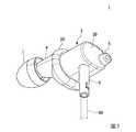
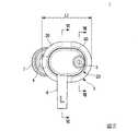
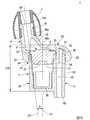
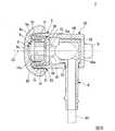
図1は、実施形態に係るイヤホン1の斜視図である。図2は、実施形態に係るイヤホン1の背面図である。図3は、実施形態に係るイヤホン1の第一側面図である。図4は、実施形態に係るイヤホン1の第二側面図である。図5は、図4のV−V断面図である。図6は、図2のVI−VI断面図である。
図1に示すように、イヤホン1は、スピーカ2(図6参照)と、スピーカ2を収容するケース3と、ケース3から突出する音通筒体4と、濾波筒体5と、ケーブル60を保持する保持筒体6と、イヤーチップ7と、を備える。<
FIG. 1 is a perspective view of an
As shown in FIG. 1, the
<スピーカ2>
図6に示すように、スピーカ2は、振動膜9と、振動膜9を支持するヨーク10と、を備える。スピーカ2は、振動膜9の振動によって発音する。
ヨーク10は、円筒状の筒壁部11を有するカップ状をなしている。以下、ヨーク10の軸線C1に沿う方向を「軸方向」、軸線C1に直交する方向を「径方向」、軸線C1回りの方向を「周方向」とする。<
As shown in FIG. 6, the
The
例えば、ヨーク10は、磁性材料で形成されている。ヨーク10は、筒壁部11、フランジ部12および底部13を備える。
フランジ部12は、筒壁部11の第一端部(開放端部)に結合されている。フランジ部12は、筒壁部11の外径よりも大きい環状を有する。フランジ部12は、筒壁部11と同軸に設けられている。フランジ部12の外周縁部は、筒壁部11の第一端部から離れる方向にオフセットしている。
底部13は、筒壁部11の第二端部(軸方向で開放端部とは反対側の端部)に結合されている。底部13は、筒壁部11と同軸に設けられた貫通孔13aを有する。For example, the
The
The
例えば、振動膜9は、絶縁性を有するフィルム材料で形成されている。振動膜9は、筒壁部11の外径よりも大きい円盤状を有する。振動膜9の中央部9aは、ドーム状に膨らんでいる。振動膜9の外周部9bは、中央部9aよりも小さく膨らんでいる。振動膜9は、空間を介してヨーク10を覆っている。振動膜9の外周縁部は、全周にわたってヨーク10のフランジ部12に接着されている。図中符号9cは、振動膜9において中央部9aと外周部9bとの間に位置する環状の境界部を示す。 For example, the vibrating
スピーカ2は、マグネット14およびコイル15を更に備える。
マグネット14は、ヨーク10内に収容されている。マグネット14は、筒壁部11と同軸の円筒状を有する。マグネット14は、底部13の貫通孔13aと実質的に同じ大きさの中空部14aを有する。マグネット14は、中空部14aを底部13の貫通孔13aに揃えるようにして底部13の第一面に配置されている。マグネット14は、底部13の第一面から筒壁部11の第一端部まで延びている。The
The
コイル15は、導線を円筒状に巻いて一体化したものである。コイル15は、振動膜9の第二面(ヨーク10と対向する面)に固定されている。軸方向から見て、コイル15は、振動膜9における境界部9cと重なっている。コイル15は、振動膜9の中央部9aを囲むように配置されている。コイル15は、ヨーク10の筒壁部11およびマグネット14のそれぞれと間隔をあけて径方向で対向している。
コイル15からは、リード線(不図示)が引き出されている。リード線は、マグネット14の中空部14aを介して、底部13の第二面側の端子部16に接続されている。The
A lead wire (not shown) is drawn out from the
<ケース3>
図5に示すように、ケース3は、スピーカ2を振動膜9の側から覆うとともに、音通筒体4が連結される音通側カバー20と、スピーカ2をヨーク10の側から覆うとともに、濾波筒体5が連結される濾波側カバー30と、を備える。<
As shown in FIG. 5, the
断面視で、音通側カバー20は、濾波側カバー30を挟んでヨーク10の径方向外側から振動膜9のヨーク10とは反対側にかけてスピーカ2を覆うドーム状をなしている。図2に示すように、音通側カバー20は、軸方向から見て長円形状の外縁を有する。音通筒体4を使用者の外耳道100に挿入した使用状態で、音通側カバー20は、耳珠102から対珠103に向けて延びる長円形状を有する(図10参照)。例えば、音通側カバー20の長軸の長さL1は、14mm以上18mm以下に設定される。本実施形態において、音通側カバー20の長軸の長さL1は、16mmである。 In cross-sectional view, the sound passing
図5に示すように、音通側カバー20は、使用者の耳甲介腔101に面する耳珠102に当接するための耳珠当接部21と、耳甲介腔101に面する対珠103に連なる耳甲介104に当接するための耳甲介当接部22と、を備える(図10参照)。
耳珠当接部21は、音通筒体4に連なるようにヨーク10の外周近傍に形成されている。耳珠当接部21は、軸方向で音通筒体4とは反対側の部分において、ヨーク10とは反対側に向けて凸の湾曲状をなしている。
耳甲介当接部22は、ヨーク10を挟んで耳珠当接部21とは反対側に形成されている。耳甲介当接部22は、ヨーク10とは反対側に向けて凸の湾曲状をなして膨出している。As shown in FIG. 5, the sound-transmitting
The
The concha of the
音通側カバー20は、濾波側カバー30との間で段部23を形成するように、濾波側カバー30を覆っている。段部23は、濾波側カバー30の全周にわたって形成されている(図2参照)。耳珠当接部21は、濾波側カバー30を挟んでヨーク10とは反対側に配置されている。耳甲介当接部22は、濾波筒体5を挟んでヨーク10とは反対側に配置されている。 The sound passage side cover 20 covers the filtering side cover 30 so as to form a
軸方向でヨーク10の振動膜9(振動膜9を支持する部分)とは反対側から見て(以下「背面視」ともいう)、音通側カバー20の外周部(濾波側カバー30を覆う部分24)は、濾波側カバー30の外周面に沿う閉じた環状をなしている(図8参照)。音通側カバー20においてヨーク10を覆う部分25は、ヨーク10の外周縁(フランジ部12の外周面)に沿う円形状をなしている(図8参照)。音通側カバー20において濾波側カバー30を覆う部分24とヨーク10を覆う部分25との間には、背面視で三日月形状をなすように軸方向に窪む凹部26が形成されている(図8参照)。 When viewed from the side opposite to the vibrating membrane 9 (the portion supporting the vibrating membrane 9) of the
図5に示すように、断面視で、濾波側カバー30は、ヨーク10の径方向外側からヨーク10の振動膜9とは反対側へ向けて延びる有底筒状をなしている。濾波側カバー30は、軸方向から見て音通側カバー20よりも小さい長円形状の外縁を有する(図2参照)。 As shown in FIG. 5, in cross-sectional view, the filter-
図6に示すように、濾波側カバー30は、ヨーク10を収容するヨーク収容部31と、保持筒体6の基部59を収容する筒体基部収容部32と、保持筒体6が挿通される筒体挿通孔33と、を有する。
ヨーク収容部31は、濾波側カバー30の第一端部寄りに配置されている。
筒体基部収容部32は、濾波側カバー30の第二端部寄りに配置されている。
軸方向においてヨーク収容部31と筒体基部収容部32との間には、音声信号を供給するための配線61が引き回されている。As shown in FIG. 6, the filter-
The
The cylindrical
A
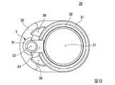
軸方向でヨーク10の振動膜9の側から見て(以下「正面視」ともいう)、ヨーク収容部31は、一部が開口した円環状(C字状)をなしている(図9参照)。正面視で、筒体基部収容部32は、ヨーク収容部31の内径よりも小さい円形状をなしている(図9参照)。 When viewed from the vibrating
図9に示すように、濾波側カバー30においてヨーク収容部31と濾波筒体5との間には、濾波側カバー30の内部空間37と濾波筒体5の内部空間53とを連通する連通路34が形成されている。背面視で、濾波側カバー30は、濾波筒体5の第一端部51を支持する三日月形状の支持壁部35を備える。濾波側カバー30において連通路34を挟む部分には、背面視で扇形状をなすように軸方向に窪む一対の穴部36が形成されている。穴部36は、濾波筒体5の内部空間53の延在方向に沿って延びている(図7参照)。 As shown in FIG. 9, in the
<音通筒体4>
図5に示すように、音通筒体4は、ケース3において振動膜9に面する部分から振動膜9のヨーク10とは反対側へ向けて突出する筒状をなしている。音通筒体4は、スピーカ2によって発音された音を使用者の耳における外耳道100に伝搬させる機能を有する(図10参照)。<Sound passage cylinder 4>
As shown in FIG. 5, the sound passage cylinder 4 has a cylindrical shape that protrudes from the portion of the
音通筒体4は、イヤーチップ7を着脱可能に支持する第一音通部41と、ケース3において振動膜9に面する部分とイヤーチップ7とを離反させるように第一音通部41とケース3とを連結する第二音通部42と、を備える。イヤーチップ7を第一音通部41に装着した状態において、イヤーチップ7とケース3とは離反している。第一音通部41および第二音通部42は、同一の部材で一体に形成されている。 The sound passage cylinder 4 has a first
第二音通部42は、第一音通部41に連結される第一連結端部42aと、ケース3に連結される第二連結端部42bと、を備える。第一音通部41は、第一連結端部42aの外径よりも小さい外径を有する。第一音通部41は、イヤーチップ7を着脱可能に支持する爪部41aを備える。第二連結端部42bは、第一連結端部42aの外径よりも大きい外径を有する。第二音通部42は、第一連結端部42aから第二連結端部42bに近づくに従って漸次拡径している。第二音通部42は、第一連結端部42aから第二連結端部42bに近づくに従ってヨーク10の軸線C1に近接するように傾斜するテーパ状をなしている。 The second
音通筒体4は、音通側カバー20において軸方向で振動膜9の半体と重なるように形成されている。音通筒体4は、ケース3の外側に向けてヨーク10の軸線C1と交差するように斜めに突出している。音通筒体4には、ケース3の内部空間と外部空間とを連通する音通孔40が形成されている。 The sound passage cylinder 4 is formed in the sound passage side cover 20 so as to overlap the half body of the vibrating
音通筒体4を外耳道100に挿入した使用状態において、音通筒体4は、ヨーク10の軸線C1においてケース3と重なる部分C10よりも耳珠102の側にオフセットしている(図10参照)。ヨーク10の軸線C1においてケース3と重なる部分C10は、軸線C1においてケース3の第一面(音通側カバー20の第一面)と第二面(濾波側カバー30の第二面)との間の部分を意味する。音通筒体4は、耳珠102から外耳道100に向けて傾斜して延びている(図10参照)。 In the use state in which the sound passage cylinder 4 is inserted into the external
音通筒体4が耳珠102から外耳道100に向けて傾斜して延びる方向において、音通筒体4の軸線C2とヨーク10の軸線C1とのなす角度をAとする。例えば、角度Aは、2度以上12度以下に設定される。本実施形態において、角度Aは、7度である。 The angle between the axis C2 of the sound passage cylinder 4 and the axis C1 of the
<濾波筒体5>
図5に示すように、濾波筒体5は、スピーカ2の背圧を逃がすようにケース3においてヨーク10に面する部分からヨーク10の振動膜9とは反対側へ向けて突出する筒状をなしている。濾波筒体5は、閾値よりも高い周波数の成分を減衰させる機能を有する。例えば、閾値は、高音域のノイズ(外部雑音)を遮断可能な周波数に設定する。<
As shown in FIG. 5, the
濾波筒体5は、ケース3の内部空間と外部空間とを連通している。濾波筒体5は、濾波側カバー30の第二面よりもケース3外部に突出している。濾波筒体5は、濾波側カバー30の長軸端部に配置されている。濾波筒体5は、濾波側カバー30の音通筒体4とは反対側の外端よりも内側に配置されている(図2参照)。 The
断面視で、濾波筒体5は、ヨーク10の軸線C1と実質的に平行な直線状をなす直管部50を備える。濾波筒体5の第一端部51は、支持壁部35と共に、音通側カバー20の凹部26に収容されている。イヤホン1は、濾波筒体5の第二端部52を通じて、ケース3の内部空間と外部空間とを連通している。連通路34は、ヨーク10の第二端部52寄りの外周近傍で濾波側カバー30の内部空間37と濾波筒体5の内部空間53とを連通している。濾波側カバー30は、濾波筒体5の第二端部52以外の部分において、密閉されている。 In sectional view, the
<保持筒体6>
図6に示すように、保持筒体6は、濾波側カバー30に結合されている。保持筒体6は、ヨーク10の軸線C1と実質的に直交する方向(図6の紙面下方向)に向けて延在している。保持筒体6には、電子機器(不図示)に接続されるケーブル60が挿通されている。ケーブル60は、保持筒体6の基部59内で抜け防止用に結び目60aが形成されている。ケーブル60には、スピーカ2に音声信号を供給するための配線61が内蔵されている。配線61は、底部13の第二面側の端子部16に接続されている。<
As shown in FIG. 6, the holding
例えば、電子機器からケーブル60を介して音声信号が供給されると、リード線を介して音声信号がコイル15に供給される。すると、コイル15が変位することにより、振動膜9が振動する。これにより、スピーカ2が発音する。スピーカ2によって発音された音は、音通孔40を通じて使用者の耳における外耳道100へ伝搬される(図10参照)。 For example, when an audio signal is supplied from the electronic device via the
<作用>
以下、本実施形態のイヤホン1の作用について説明する。
図10は、実施形態に係るイヤホン1の使用状態の説明図である。図11は、比較例に係るイヤホン1Xの使用状態の説明図である。
まず、比較例について説明する。
図11に示すように、比較例に係るイヤホン1Xは、使用者の耳珠102、対珠103、耳甲介104で囲まれた耳甲介腔101内に、振動膜9Xを耳甲介104に近接させるようにしてケース3Xを挿入する構成を有する。比較例では、耳甲介腔101から鼓膜へ延びる外耳道100内へ、ヨーク10Xの軸線に対して斜めに突設させた音通筒体4Xを挿入する。音通筒体4Xには、可撓性を有するイヤーチップ7Xが嵌められている。イヤーチップ7Xは、外耳道100の内壁に弾性的に当接する。<Action>
The operation of the
FIG. 10 is an explanatory diagram of a usage state of the
First, a comparative example will be described.
As shown in FIG. 11, in the
次に、本実施形態について図10を参照して説明する。
本実施形態においては、イヤホン1を使用する際、濾波筒体5がケース3を挟んで外耳道100とは反対側へ向けて突出し、閾値よりも高い周波数の成分を減衰させるため、濾波筒体5をローパスフィルタのように機能させることができる。したがって、比較例よりも高音域の外部雑音の侵入を抑制することができる。
加えて、本実施形態においては、イヤホン1を使用する際、第二音通部42の長さ分だけ、音通筒体4を外耳道100の奥へ入り込ませることができる。そのため、比較例よりも外耳道100の奥の部分でイヤーチップ7を当接させることができる。
更に、本実施形態においては、イヤホン1を使用する際、耳珠当接部21の段部23を耳珠102でおさえることができる。そのため、比較例よりもイヤホン1を外れにくくすることができる。Next, this embodiment will be described with reference to FIG.
In the present embodiment, when the
In addition, in the present embodiment, when the
Further, in the present embodiment, when the
以上説明したように、本実施形態に係るイヤホン1は、振動膜9と、振動膜9を支持するヨーク10と、を有し、振動膜9の振動によって発音するスピーカ2と、スピーカ2を収容するケース3と、ケース3において振動膜9に面する部分から振動膜9のヨーク10とは反対側へ向けて突出する筒状をなすとともに、スピーカ2によって発音された音を使用者の耳における外耳道100に伝搬させるための音通筒体4と、スピーカ2の背圧を逃がすようにケース3においてヨーク10に面する部分からヨーク10の振動膜9とは反対側へ向けて突出する筒状をなすとともに、閾値よりも高い周波数の成分を減衰させる濾波筒体5と、を備える。
この構成によれば、イヤホン1を使用する際、濾波筒体5がケース3を挟んで外耳道100とは反対側へ向けて突出し、閾値よりも高い周波数の成分を減衰させるため、濾波筒体5をローパスフィルタ(ハイカットフィルタ)のように機能させることができる。言い換えると、濾波筒体5を音響イナータンス(電気系のインダクタンスに対応する音響素子)として機能させることができる。したがって、高音域の外部雑音の侵入を抑制することができる。As described above, the
According to this configuration, when the
上記実施形態では、音通筒体4は、イヤーチップ7を着脱可能に支持する第一音通部41と、ケース3において振動膜9に面する部分とイヤーチップ7と離反させるように第一音通部41とケース3とを連結する第二音通部42と、を備えることで、以下の効果を奏する。
イヤホン1を使用する際、第二音通部42の長さ分だけ、第一音通部41を外耳道100の奥へ入り込ませることができるため、外部雑音の侵入を更に抑制することができる。In the above-described embodiment, the sound-passing tubular body 4 includes the first sound-passing
When the
上記実施形態では、第二音通部42は、第一音通部41に連結される第一連結端部42aと、ケース3に連結される第二連結端部42bと、を備え、第一音通部41は、第一連結端部42aの外径よりも小さい外径を有し、第二連結端部42bは、第一連結端部42aの外径よりも大きい外径を有し、第二音通部42は、第一連結端部42aから第二連結端部42bに近づくに従って漸次拡径していることで、以下の効果を奏する。
イヤホン1を使用する際、第一音通部41を外耳道100の奥へ入り込ませつつ、第二音通部42を外耳道100の入口近傍の広い範囲で介在させることができるため、外部雑音の侵入を更に抑制することができる。In the above embodiment, the second
When the
上記実施形態では、ケース3は、音通筒体4に連なるようにヨーク10の外周近傍に形成され、音通筒体4とは反対側の部分において、ヨーク10とは反対側に向けて凸の湾曲状をなすとともに、使用者の耳甲介腔101に面する耳珠102に当接するための耳珠当接部21を備えることで、以下の効果を奏する。
イヤホン1を使用する際、耳珠当接部21を耳珠102に広い範囲で接触させやすいため、装着性を向上することができる。In the above-described embodiment, the
When the
上記実施形態では、ケース3は、ヨーク10を挟んで耳珠当接部21とは反対側に形成され、ヨーク10とは反対側に向けて凸の湾曲状をなして膨出するとともに、耳甲介腔101に面する対珠103に連なる耳甲介104に当接するための耳甲介当接部22を更に備えることで、以下の効果を奏する。
イヤホン1を使用する際、耳珠当接部21を耳珠102に当接させつつ、耳甲介当接部22を耳甲介104に広い範囲で接触させやすいため、装着性を更に向上することができる。In the above-described embodiment, the
When the
上記実施形態では、ケース3は、耳珠当接部21および耳甲介当接部22を有し、スピーカ2を振動膜9の側から覆うとともに、音通筒体4が連結される音通側カバー20と、スピーカ2をヨーク10の側から覆うとともに、濾波筒体5が連結される濾波側カバー30と、を備えることで、以下の効果を奏する。
音通側カバー20と濾波側カバー30とを別個独立に製造することができるため、製造効率を向上することができる。In the above-described embodiment, the
Since the sound passing
上記実施形態では、音通筒体4を外耳道100に挿入した使用状態でヨーク10の軸線C1に沿う方向から見て、音通側カバー20は、耳珠102から対珠103に向けて延びる長円形状を有することで、以下の効果を奏する。
イヤホン1を使用する際、音通側カバー20の長軸端部を耳珠102側および対珠103側で支持しやすいため、装着性を更に向上することができる。In the above-described embodiment, the sound
When the
上記実施形態では、ヨーク10の軸線C1に沿う方向から見て、長円形状を有する音通側カバー20の長軸の長さL1は、14mm以上18mm以下であることで、以下の効果を奏する。
音通側カバー20の長軸の長さL1が14mm未満または18mmを超える場合と比較して、装着性を更に向上することができる。In the above embodiment, when viewed from the direction along the axis C1 of the
Compared with the case where the length L1 of the major axis of the sound
上記実施形態では、音通側カバー20は、濾波側カバー30との間で段部23を形成するように、濾波側カバー30を覆い、耳珠当接部21は、濾波側カバー30を挟んでヨーク10とは反対側に配置され、耳甲介当接部22は、濾波筒体5を挟んでヨーク10とは反対側に配置されていることで、以下の効果を奏する。
イヤホン1を使用する際、耳珠当接部21の段部23を耳珠102でおさえることができるため、装着性を更に向上することができる。加えて、イヤホン1を使用する際、耳甲介当接部22の段部23によって耳甲介104と濾波筒体5との間に隙間を介在させ、濾波筒体5が耳に触れにくくすることができる。In the above-described embodiment, the sound passage side cover 20 covers the filtering side cover 30 so as to form the
When the
上記実施形態では、音通筒体4を外耳道100に挿入した使用状態において、音通筒体4は、ヨーク10の軸線C1においてケース3と重なる部分よりも使用者の耳甲介腔101に面する耳珠102の側にオフセットするとともに、耳珠102から外耳道100に向けて傾斜して延びていることで、以下の効果を奏する。
イヤホン1を使用する際、使用者の外耳道100に沿って自然な角度で音通筒体4を外耳道100へ挿入することができるため、装着性を向上することができる。In the above-described embodiment, in the use state in which the sound communication tubular body 4 is inserted into the external
When the
上記実施形態では、音通筒体4が耳珠102から外耳道100に向けて傾斜して延びる方向において、音通筒体4の軸線C2と、ヨーク10の軸線C1とのなす角度をAとしたとき、角度Aは、2度以上12度以下であることで、以下の効果を奏する。
角度Aが2度未満または12度を超える場合と比較して、装着性を更に向上することができる。In the above embodiment, the angle between the axis C2 of the sound passage cylinder 4 and the axis C1 of the
The wearability can be further improved as compared with the case where the angle A is less than 2 degrees or more than 12 degrees.
<変形例>
上記実施形態では、音通筒体4を外耳道100に挿入した使用状態において、音通筒体4が耳珠102から外耳道100に向けて傾斜して延びている例を挙げて説明したが、これに限らない。
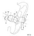
例えば、図12に示すように、音通筒体204を外耳道100に挿入した使用状態において、音通筒体204は、使用者の耳甲介腔101に面する耳珠102(図10参照)から使用者の頭部に向けて傾斜して延びていてもよい。
この構成によれば、イヤホンを使用する際、使用者の外耳道100に沿って自然な角度で音通筒体204を外耳道100へ挿入することができるため、装着性を向上することができる。<Modification>
In the above-described embodiment, an example in which the sound communication tubular body 4 extends obliquely from the
For example, as shown in FIG. 12, in the use state in which the sound-passing
According to this configuration, when the earphone is used, the sound
例えば、音通筒体204が耳珠102から頭部に向けて傾斜して延びる方向において、音通筒体204の軸線C2と、ヨーク10の軸線C1とのなす角度をBとしたとき、角度Bは、5度以上35度以下であることが好ましい。
この構成によれば、角度Bが5度未満または35度を超える場合と比較して、装着性を更に向上することができる。For example, when the angle between the axis C2 of the
With this configuration, the wearability can be further improved as compared with the case where the angle B is less than 5 degrees or more than 35 degrees.
本変形例において、角度Bは、20度である。
この構成によれば、一般に外耳道100が耳珠102から頭部に向けて傾斜する角度は約20度であるため、イヤホンを使用する際、使用者の外耳道100に沿って自然な角度で音通筒体204を外耳道100へ挿入しやすい。In this modification, the angle B is 20 degrees.
According to this configuration, since the external
上記実施形態では、左耳用のイヤホン1を挙げて説明したが、これに限らない。右耳用のイヤホンについても本発明を適用可能である。例えば、左耳用のイヤホンと右耳用のイヤホンとを、左右対称構造(左右勝手違い部品)とすることで対応可能である。 Although the
なお、上記実施形態は、例として提示したものであり、発明の範囲を限定することは意図していない。上記実施形態は、その他の様々な形態で実施されることが可能であり、発明の要旨を逸脱しない範囲で、種々の省略、置き換え、組み合わせ、変更が可能である。上記実施形態とその変形は、発明の範囲と発明の要旨に含まれると同様に、特許請求の範囲に記載された発明とその均等の範囲に含まれるものである。 The above embodiment is presented as an example and is not intended to limit the scope of the invention. The above-described embodiment can be implemented in various other forms, and various omissions, replacements, combinations, and changes can be made without departing from the spirit of the invention. The above-described embodiment and its modifications are included in the scope of the invention and the scope of the invention, and are also included in the invention described in the claims and the equivalent scope thereof.
以下、実施例により本発明をより具体的に説明するが、本発明は以下の実施例に限定されるものではない。 Hereinafter, the present invention will be described more specifically by way of examples, but the present invention is not limited to the following examples.
[実施例]
実施例のイヤホンは、本実施形態に係る濾波筒体5を有するイヤホン1を用いた(図5参照)。実施例では、音通筒体4が耳珠102から外耳道100に向けて傾斜して延びる方向において、音通筒体4の軸線C2とヨーク10の軸線C1とのなす角度Aは、7度とした。[Example]
As the earphone of the example, the
[比較例1]
比較例1は、イヤホンを人工耳に装着しない状態とした。比較例1では、ノイズ音源を直に人工耳で拾う構成とした。[Comparative Example 1]
In Comparative Example 1, the earphone was not attached to the artificial ear. In Comparative Example 1, the noise source is directly picked up by the artificial ear.
[比較例2]
比較例2のイヤホンは、制動孔を有するイヤホン(パナソニック社製の型式「HDE1」)を用いた(不図示)。比較例2は、本実施形態に係る濾波筒体5を有しない。[Comparative example 2]
As the earphone of Comparative Example 2, an earphone having a braking hole (model “HDE1” manufactured by Panasonic Corporation) was used (not shown). Comparative Example 2 does not have the
[比較例3]
比較例3のイヤホンは、アクティブノイズキャンセルを有するイヤホン(ソニー社製の型式「MDR−AC22」)を用いた(不図示)。比較例3は、本実施形態に係る濾波筒体5を有しない。比較例3では、イヤホンを装着した状態で、ノイズキャンセルスイッチをオン(アクティブノイズキャンセルオン)とした。[Comparative Example 3]
As the earphone of Comparative Example 3, an earphone having active noise cancellation (model “MDR-AC22” manufactured by Sony Corporation) was used (not shown). Comparative Example 3 does not have the
[比較例4]
比較例4は、比較例3と同じイヤホンを用い、イヤホンを装着した状態で、ノイズキャンセルスイッチをオフ(アクティブノイズキャンセルオフ)とした。[Comparative Example 4]
In Comparative Example 4, the same earphone as in Comparative Example 3 was used, and the noise cancel switch was turned off (active noise cancel off) while the earphone was worn.
[実験例]
実施例、比較例1〜4のそれぞれにおいて、音波の周波数特性を測定した。周波数測定器は、使用者の耳の形状を模造した人工耳において音波の周波数を測定するものを用いた。[Experimental example]
In each of Examples and Comparative Examples 1 to 4, frequency characteristics of sound waves were measured. The frequency measuring device used is one that measures the frequency of a sound wave in an artificial ear that imitates the shape of the user's ear.
図13は、ホワイトノイズによる、音波の周波数特性の測定結果を示す図である。図13において、横軸は音波の周波数[Hz]、縦軸は音波の音圧レベル[dB]である。図13において、グラフR1(実線)は実施例、グラフR2(破線)は比較例1,グラフR3(二点鎖線)は比較例2をそれぞれ示す。 FIG. 13 is a diagram showing a measurement result of frequency characteristics of sound waves by white noise. In FIG. 13, the horizontal axis represents the frequency [Hz] of the sound wave, and the vertical axis represents the sound pressure level [dB] of the sound wave. In FIG. 13, the graph R1 (solid line) shows the example, the graph R2 (broken line) shows the comparative example 1, and the graph R3 (two-dot chain line) shows the comparative example 2, respectively.
図13に示すように、実施例のイヤホン1では、広い周波数域で、比較例1および比較例2のそれぞれよりも音圧レベルが低減したことを確認できた。実施例では、周波数が100Hz付近のときに、最大音圧レベルが−25.6dBであった。 As shown in FIG. 13, it was confirmed that in the
図14は、ピンクノイズによる、音波の周波数特性の測定結果を示す図である。図14において、横軸は音波の周波数[Hz]、縦軸は音波の音圧レベル[dB]である。図14において、グラフS1(実線)は実施例、グラフS2(破線)は比較例1,グラフS3(二点鎖線)は比較例2をそれぞれ示す。 FIG. 14 is a diagram showing a measurement result of frequency characteristics of sound waves by pink noise. In FIG. 14, the horizontal axis represents the frequency [Hz] of the sound wave, and the vertical axis represents the sound pressure level [dB] of the sound wave. In FIG. 14, a graph S1 (solid line) shows an example, a graph S2 (broken line) shows a comparative example 1, and a graph S3 (two-dot chain line) shows a comparative example 2.
図14に示すように、実施例のイヤホン1では、広い周波数域で、比較例1および比較例2のそれぞれよりも音圧レベルが低減したことを確認できた。実施例では、周波数が100Hz付近のときに、最大音圧レベルが−16.5dBであった。 As shown in FIG. 14, it was confirmed that in the
図15は、アクティブノイズキャンセルのデータを含む、ホワイトノイズによる、音波の周波数特性の測定結果を示す図である。図15において、横軸は音波の周波数[Hz]、縦軸は音波の音圧レベル[dB]である。図15において、グラフT1(実線)は比較例3、グラフT2(破線)は比較例1,グラフT3(二点鎖線)は比較例4をそれぞれ示す。 FIG. 15 is a diagram showing the measurement result of the frequency characteristic of the sound wave by the white noise including the data of the active noise cancellation. In FIG. 15, the horizontal axis indicates the frequency [Hz] of the sound wave, and the vertical axis indicates the sound pressure level [dB] of the sound wave. In FIG. 15, a graph T1 (solid line) shows Comparative Example 3, a graph T2 (broken line) shows Comparative Example 1, and a graph T3 (two-dot chain line) shows Comparative Example 4.
図15に示すように、比較例3のイヤホン1では、広い周波数域で、比較例1および比較例4のそれぞれよりも音圧レベルが低減したことを確認できた。比較例3では、最大音圧レベルが−16.0dBであった。
これに対し、実施例のホワイトノイズによる結果では、最大音圧レベルが−25.6dBであり、実施例は比較例3に対し、音圧レベルが9.6dB低減した。したがって、アクティブノイズキャンセルを有するイヤホンに対し、実施例のイヤホン(挿入式パッシブ・ノイズキャンセル・イヤホン)の優位性を確認できた。As shown in FIG. 15, it was confirmed that the
On the other hand, as a result of the white noise of the example, the maximum sound pressure level was −25.6 dB, and the example reduced the sound pressure level by 9.6 dB as compared with the comparative example 3. Therefore, the superiority of the earphone of the embodiment (insertion-type passive noise-canceling earphone) was confirmed over the earphone having active noise cancellation.
1…イヤホン(挿入式パッシブ・ノイズキャンセル・イヤホン)
2…スピーカ
3…ケース
4…音通筒体
5…濾波筒体
7…イヤーチップ
9…振動膜
10…ヨーク
20…音通側カバー
21…耳珠当接部
22…耳甲介当接部
23…段部
30…濾波側カバー
41…第一音通部
42…第二音通部
42a…第一連結端部
42b…第二連結端部
100…外耳道
101…耳甲介腔
102…耳珠
103…対珠
104…耳甲介
204…音通筒体
C1…ヨークの軸線
C2…音通筒体の軸線
L1…音通側カバーの長軸の長さ1... Earphone (insertion type passive noise canceling earphone)
2...
Claims (13)
Translated fromJapanese前記スピーカを収容するケースと、
前記ケースにおいて前記振動膜に面する部分から前記振動膜の前記ヨークとは反対側へ向けて突出する筒状をなすとともに、前記スピーカによって発音された音を使用者の耳における外耳道に伝搬させるための音通筒体と、
前記スピーカの背圧を逃がすように前記ケースにおいて前記ヨークに面する部分から前記ヨークの前記振動膜とは反対側へ向けて突出する筒状をなすとともに、閾値よりも高い周波数の成分を減衰させる濾波筒体と、を備えることを特徴とする挿入式パッシブ・ノイズキャンセル・イヤホン。A speaker having a vibrating film and a yoke that supports the vibrating film, and a speaker that emits sound by vibration of the vibrating film;
A case accommodating the speaker,
In order to propagate the sound generated by the speaker to the external auditory meatus of the user's ear while forming a cylindrical shape projecting from the portion of the case facing the vibrating membrane toward the side opposite to the yoke of the vibrating membrane. Sound passage cylinder,
The case has a cylindrical shape that protrudes from a portion of the case facing the yoke toward the side opposite to the vibrating membrane so as to release the back pressure of the speaker, and attenuates a component having a frequency higher than a threshold value. An insertion-type passive noise-canceling earphone, which comprises: a filtering cylinder.
イヤーチップを着脱可能に支持する第一音通部と、
前記ケースにおいて前記振動膜に面する部分と前記イヤーチップと離反させるように前記第一音通部と前記ケースとを連結する第二音通部と、を備えることを特徴とする請求項1に記載の挿入式パッシブ・ノイズキャンセル・イヤホン。The sound passage cylinder is
A first sound passage portion that detachably supports the ear tip,
The second sound passage portion that connects the first sound passage portion and the case so as to separate the portion facing the vibrating film and the ear tip in the case from each other. Insertion type passive noise canceling earphone described.
前記第一音通部に連結される第一連結端部と、
前記ケースに連結される第二連結端部と、を備え、
前記第一音通部は、前記第一連結端部の外径よりも小さい外径を有し、
前記第二連結端部は、前記第一連結端部の外径よりも大きい外径を有し、
前記第二音通部は、前記第一連結端部から前記第二連結端部に近づくに従って漸次拡径していることを特徴とする請求項2に記載の挿入式パッシブ・ノイズキャンセル・イヤホン。The second sound passing portion,
A first connecting end connected to the first sound passage,
A second connection end connected to the case,
The first sound passage portion has an outer diameter smaller than the outer diameter of the first connection end portion,
The second connecting end has an outer diameter larger than the outer diameter of the first connecting end,
The insertion type passive noise canceling earphone according to claim 2, wherein the second sound passage portion gradually increases in diameter from the first connection end portion toward the second connection end portion.
前記耳珠当接部および前記耳甲介当接部を有し、前記スピーカを前記振動膜の側から覆うとともに、前記音通筒体が連結される音通側カバーと、
前記スピーカを前記ヨークの側から覆うとともに、前記濾波筒体が連結される濾波側カバーと、を備えることを特徴とする請求項5に記載の挿入式パッシブ・ノイズキャンセル・イヤホン。The case is
A sound passage side cover having the tragus contact portion and the concha contact portion, covering the speaker from the side of the vibrating membrane and connecting the sound passage cylinder to the sound passage side cover;
The insertion-type passive noise canceling earphone according to claim 5, further comprising: a filter side cover that covers the speaker from the yoke side and to which the filtering cylinder is connected.
前記耳珠当接部は、前記濾波側カバーを挟んで前記ヨークとは反対側に配置され、
前記耳甲介当接部は、前記濾波筒体を挟んで前記ヨークとは反対側に配置されていることを特徴とする請求項6から8のいずれか一項に記載の挿入式パッシブ・ノイズキャンセル・イヤホン。The sound passage side cover covers the filtering side cover so as to form a step portion with the filtering side cover,
The tragus contact portion is disposed on the opposite side of the yoke with the filtering side cover interposed therebetween,
9. The insertion type passive noise according to claim 6, wherein the concha of the concha is arranged on the opposite side of the yoke with the filtering cylinder interposed therebetween. Cancel earphones.
前記音通筒体は、前記ヨークの軸線において前記ケースと重なる部分よりも前記使用者の耳甲介腔に面する耳珠の側にオフセットするとともに、前記耳珠から前記外耳道に向けて傾斜して延びていることを特徴とする請求項1から9のいずれか一項に記載の挿入式パッシブ・ノイズキャンセル・イヤホン。In a use state in which the sound passage tubular body is inserted into the ear canal,
The sound passage cylinder is offset toward the tragus side facing the concha cavity of the user from the portion overlapping the case in the axis line of the yoke, and is inclined from the tragus toward the ear canal. The insertion type passive noise canceling earphone according to any one of claims 1 to 9, wherein the insertion type passive noise canceling earphone is extended.
前記角度Aは、2度以上12度以下であることを特徴とする請求項10に記載の挿入式パッシブ・ノイズキャンセル・イヤホン。When the angle formed by the axis of the sound passage tube and the axis of the yoke in the direction in which the sound passage tube extends from the tragus toward the external ear canal is A,
The insertion type passive noise canceling earphone according to claim 10, wherein the angle A is 2 degrees or more and 12 degrees or less.
前記音通筒体は、前記使用者の耳甲介腔に面する耳珠から前記使用者の頭部に向けて傾斜して延びていることを特徴とする請求項1から11のいずれか一項に記載の挿入式パッシブ・ノイズキャンセル・イヤホン。In a use state in which the sound passage tubular body is inserted into the ear canal,
12. The sound-passing cylinder extends obliquely toward the head of the user from the tragus facing the concha of the user's concha, and is inclined. Insertion type passive noise canceling earphone described in the item.
前記角度Bは、5度以上35度以下であることを特徴とする請求項12に記載の挿入式パッシブ・ノイズキャンセル・イヤホン。When the angle between the axis of the sound passage cylinder and the axis of the yoke is B in the direction in which the sound passage cylinder extends from the tragus toward the head,
The insertion type passive noise canceling earphone according to claim 12, wherein the angle B is 5 degrees or more and 35 degrees or less.
Priority Applications (1)
| Application Number | Priority Date | Filing Date | Title |
|---|---|---|---|
| JP2019004502AJP7239152B2 (en) | 2019-01-15 | 2019-01-15 | Insertable Passive Noise Canceling Earbuds |
Applications Claiming Priority (1)
| Application Number | Priority Date | Filing Date | Title |
|---|---|---|---|
| JP2019004502AJP7239152B2 (en) | 2019-01-15 | 2019-01-15 | Insertable Passive Noise Canceling Earbuds |
Publications (2)
| Publication Number | Publication Date |
|---|---|
| JP2020113925Atrue JP2020113925A (en) | 2020-07-27 |
| JP7239152B2 JP7239152B2 (en) | 2023-03-14 |
Family
ID=71667347
Family Applications (1)
| Application Number | Title | Priority Date | Filing Date |
|---|---|---|---|
| JP2019004502AActiveJP7239152B2 (en) | 2019-01-15 | 2019-01-15 | Insertable Passive Noise Canceling Earbuds |
Country Status (1)
| Country | Link |
|---|---|
| JP (1) | JP7239152B2 (en) |
Citations (9)
| Publication number | Priority date | Publication date | Assignee | Title |
|---|---|---|---|---|
| JPH07170591A (en)* | 1994-10-20 | 1995-07-04 | Sony Corp | Headphone |
| WO2010005039A1 (en)* | 2008-07-09 | 2010-01-14 | パイオニア株式会社 | Earphone |
| JP2014014074A (en)* | 2012-06-20 | 2014-01-23 | Apple Inc | Earphone with acoustic tuning mechanism |
| JP3188830U (en)* | 2012-11-21 | 2014-02-13 | 大阪京實業股▲分▼有限公司 | Canal type earphone |
| JP2015005790A (en)* | 2013-06-19 | 2015-01-08 | 賢太 田中 | Earphone device |
| JP2018006784A (en)* | 2016-06-27 | 2018-01-11 | オンキヨー株式会社 | Earphone |
| JP2018011102A (en)* | 2016-07-11 | 2018-01-18 | 株式会社Jvcケンウッド | earphone |
| US20180035192A1 (en)* | 2015-02-10 | 2018-02-01 | Phazon Inc. | Wireless earbud |
| US20180167713A1 (en)* | 2016-12-09 | 2018-06-14 | Kingston Technology Corp. | Headphones with an ergonomic cushion and an ergonomic cushion thereof |
- 2019
- 2019-01-15JPJP2019004502Apatent/JP7239152B2/enactiveActive
Patent Citations (9)
| Publication number | Priority date | Publication date | Assignee | Title |
|---|---|---|---|---|
| JPH07170591A (en)* | 1994-10-20 | 1995-07-04 | Sony Corp | Headphone |
| WO2010005039A1 (en)* | 2008-07-09 | 2010-01-14 | パイオニア株式会社 | Earphone |
| JP2014014074A (en)* | 2012-06-20 | 2014-01-23 | Apple Inc | Earphone with acoustic tuning mechanism |
| JP3188830U (en)* | 2012-11-21 | 2014-02-13 | 大阪京實業股▲分▼有限公司 | Canal type earphone |
| JP2015005790A (en)* | 2013-06-19 | 2015-01-08 | 賢太 田中 | Earphone device |
| US20180035192A1 (en)* | 2015-02-10 | 2018-02-01 | Phazon Inc. | Wireless earbud |
| JP2018006784A (en)* | 2016-06-27 | 2018-01-11 | オンキヨー株式会社 | Earphone |
| JP2018011102A (en)* | 2016-07-11 | 2018-01-18 | 株式会社Jvcケンウッド | earphone |
| US20180167713A1 (en)* | 2016-12-09 | 2018-06-14 | Kingston Technology Corp. | Headphones with an ergonomic cushion and an ergonomic cushion thereof |
Also Published As
| Publication number | Publication date |
|---|---|
| JP7239152B2 (en) | 2023-03-14 |
Similar Documents
| Publication | Publication Date | Title |
|---|---|---|
| US11057695B2 (en) | In-ear headphone device with active noise control | |
| JP4652474B1 (en) | earphone | |
| US8139806B2 (en) | Earphone for placement in an ear | |
| JP6380504B2 (en) | headphone | |
| CN109862486B (en) | Loudspeaker assembly | |
| JP5662254B2 (en) | Audio output device | |
| JP2014155145A (en) | Earphone microphone | |
| CN216600066U (en) | Speaker and audio output device | |
| CN119366198A (en) | Sound signal output device | |
| US10878798B2 (en) | Earphone with an active noise cancelling feedback microphone arranged at the rear-side of a speaker diaphragm | |
| JP2019145963A (en) | earphone | |
| TW202425662A (en) | Acoustic transducer unit | |
| WO2016181431A1 (en) | Sound-isolating earphone having communication portion | |
| WO2020031534A1 (en) | Acoustic output device | |
| WO2016166785A1 (en) | Earphone with communicating tube | |
| JP2018207484A (en) | headphone | |
| CN106464997A (en) | Headphone unit | |
| JP5253075B2 (en) | Headphone unit and headphones | |
| JP7239152B2 (en) | Insertable Passive Noise Canceling Earbuds | |
| JP7289133B2 (en) | Double-sided listening earphone | |
| JP7347927B2 (en) | Electroacoustic transducers and audio equipment | |
| JP2020043547A (en) | Earphone speaker | |
| WO2020148819A1 (en) | Intra-concha earphones | |
| JP6583226B2 (en) | headphone | |
| CN205754759U (en) | earphone |
Legal Events
| Date | Code | Title | Description |
|---|---|---|---|
| A621 | Written request for application examination | Free format text:JAPANESE INTERMEDIATE CODE: A621 Effective date:20211013 | |
| A977 | Report on retrieval | Free format text:JAPANESE INTERMEDIATE CODE: A971007 Effective date:20220826 | |
| A131 | Notification of reasons for refusal | Free format text:JAPANESE INTERMEDIATE CODE: A131 Effective date:20221004 | |
| A521 | Request for written amendment filed | Free format text:JAPANESE INTERMEDIATE CODE: A523 Effective date:20221017 | |
| TRDD | Decision of grant or rejection written | ||
| A01 | Written decision to grant a patent or to grant a registration (utility model) | Free format text:JAPANESE INTERMEDIATE CODE: A01 Effective date:20230214 | |
| A61 | First payment of annual fees (during grant procedure) | Free format text:JAPANESE INTERMEDIATE CODE: A61 Effective date:20230222 | |
| R150 | Certificate of patent or registration of utility model | Ref document number:7239152 Country of ref document:JP Free format text:JAPANESE INTERMEDIATE CODE: R150 |