JP2020110632A - Wound treatment method and device - Google Patents
Wound treatment method and deviceDownload PDFInfo
- Publication number
- JP2020110632A JP2020110632AJP2020048977AJP2020048977AJP2020110632AJP 2020110632 AJP2020110632 AJP 2020110632AJP 2020048977 AJP2020048977 AJP 2020048977AJP 2020048977 AJP2020048977 AJP 2020048977AJP 2020110632 AJP2020110632 AJP 2020110632A
- Authority
- JP
- Japan
- Prior art keywords
- negative pressure
- wound site
- unit
- wound
- closed space
- Prior art date
- Legal status (The legal status is an assumption and is not a legal conclusion. Google has not performed a legal analysis and makes no representation as to the accuracy of the status listed.)
- Pending
Links
Images


Classifications
- A—HUMAN NECESSITIES
- A61—MEDICAL OR VETERINARY SCIENCE; HYGIENE
- A61M—DEVICES FOR INTRODUCING MEDIA INTO, OR ONTO, THE BODY; DEVICES FOR TRANSDUCING BODY MEDIA OR FOR TAKING MEDIA FROM THE BODY; DEVICES FOR PRODUCING OR ENDING SLEEP OR STUPOR
- A61M3/00—Medical syringes, e.g. enemata; Irrigators
- A61M3/02—Enemata; Irrigators
- A61M3/0204—Physical characteristics of the irrigation fluid, e.g. conductivity or turbidity
- A61M3/022—Volume; Flow rate
- A—HUMAN NECESSITIES
- A61—MEDICAL OR VETERINARY SCIENCE; HYGIENE
- A61M—DEVICES FOR INTRODUCING MEDIA INTO, OR ONTO, THE BODY; DEVICES FOR TRANSDUCING BODY MEDIA OR FOR TAKING MEDIA FROM THE BODY; DEVICES FOR PRODUCING OR ENDING SLEEP OR STUPOR
- A61M1/00—Suction or pumping devices for medical purposes; Devices for carrying-off, for treatment of, or for carrying-over, body-liquids; Drainage systems
- A61M1/71—Suction drainage systems
- A61M1/74—Suction control
- A—HUMAN NECESSITIES
- A61—MEDICAL OR VETERINARY SCIENCE; HYGIENE
- A61M—DEVICES FOR INTRODUCING MEDIA INTO, OR ONTO, THE BODY; DEVICES FOR TRANSDUCING BODY MEDIA OR FOR TAKING MEDIA FROM THE BODY; DEVICES FOR PRODUCING OR ENDING SLEEP OR STUPOR
- A61M1/00—Suction or pumping devices for medical purposes; Devices for carrying-off, for treatment of, or for carrying-over, body-liquids; Drainage systems
- A61M1/71—Suction drainage systems
- A61M1/73—Suction drainage systems comprising sensors or indicators for physical values
- A—HUMAN NECESSITIES
- A61—MEDICAL OR VETERINARY SCIENCE; HYGIENE
- A61M—DEVICES FOR INTRODUCING MEDIA INTO, OR ONTO, THE BODY; DEVICES FOR TRANSDUCING BODY MEDIA OR FOR TAKING MEDIA FROM THE BODY; DEVICES FOR PRODUCING OR ENDING SLEEP OR STUPOR
- A61M1/00—Suction or pumping devices for medical purposes; Devices for carrying-off, for treatment of, or for carrying-over, body-liquids; Drainage systems
- A61M1/84—Drainage tubes; Aspiration tips
- A61M1/85—Drainage tubes; Aspiration tips with gas or fluid supply means, e.g. for supplying rinsing fluids or anticoagulants
- A—HUMAN NECESSITIES
- A61—MEDICAL OR VETERINARY SCIENCE; HYGIENE
- A61M—DEVICES FOR INTRODUCING MEDIA INTO, OR ONTO, THE BODY; DEVICES FOR TRANSDUCING BODY MEDIA OR FOR TAKING MEDIA FROM THE BODY; DEVICES FOR PRODUCING OR ENDING SLEEP OR STUPOR
- A61M1/00—Suction or pumping devices for medical purposes; Devices for carrying-off, for treatment of, or for carrying-over, body-liquids; Drainage systems
- A61M1/90—Negative pressure wound therapy devices, i.e. devices for applying suction to a wound to promote healing, e.g. including a vacuum dressing
- A61M1/92—Negative pressure wound therapy devices, i.e. devices for applying suction to a wound to promote healing, e.g. including a vacuum dressing with liquid supply means
- A—HUMAN NECESSITIES
- A61—MEDICAL OR VETERINARY SCIENCE; HYGIENE
- A61M—DEVICES FOR INTRODUCING MEDIA INTO, OR ONTO, THE BODY; DEVICES FOR TRANSDUCING BODY MEDIA OR FOR TAKING MEDIA FROM THE BODY; DEVICES FOR PRODUCING OR ENDING SLEEP OR STUPOR
- A61M1/00—Suction or pumping devices for medical purposes; Devices for carrying-off, for treatment of, or for carrying-over, body-liquids; Drainage systems
- A61M1/90—Negative pressure wound therapy devices, i.e. devices for applying suction to a wound to promote healing, e.g. including a vacuum dressing
- A61M1/94—Negative pressure wound therapy devices, i.e. devices for applying suction to a wound to promote healing, e.g. including a vacuum dressing with gas supply means
- A—HUMAN NECESSITIES
- A61—MEDICAL OR VETERINARY SCIENCE; HYGIENE
- A61M—DEVICES FOR INTRODUCING MEDIA INTO, OR ONTO, THE BODY; DEVICES FOR TRANSDUCING BODY MEDIA OR FOR TAKING MEDIA FROM THE BODY; DEVICES FOR PRODUCING OR ENDING SLEEP OR STUPOR
- A61M1/00—Suction or pumping devices for medical purposes; Devices for carrying-off, for treatment of, or for carrying-over, body-liquids; Drainage systems
- A61M1/90—Negative pressure wound therapy devices, i.e. devices for applying suction to a wound to promote healing, e.g. including a vacuum dressing
- A61M1/96—Suction control thereof
- A—HUMAN NECESSITIES
- A61—MEDICAL OR VETERINARY SCIENCE; HYGIENE
- A61M—DEVICES FOR INTRODUCING MEDIA INTO, OR ONTO, THE BODY; DEVICES FOR TRANSDUCING BODY MEDIA OR FOR TAKING MEDIA FROM THE BODY; DEVICES FOR PRODUCING OR ENDING SLEEP OR STUPOR
- A61M27/00—Drainage appliance for wounds or the like, i.e. wound drains, implanted drains
- A—HUMAN NECESSITIES
- A61—MEDICAL OR VETERINARY SCIENCE; HYGIENE
- A61M—DEVICES FOR INTRODUCING MEDIA INTO, OR ONTO, THE BODY; DEVICES FOR TRANSDUCING BODY MEDIA OR FOR TAKING MEDIA FROM THE BODY; DEVICES FOR PRODUCING OR ENDING SLEEP OR STUPOR
- A61M37/00—Other apparatus for introducing media into the body; Percutany, i.e. introducing medicines into the body by diffusion through the skin
- A—HUMAN NECESSITIES
- A61—MEDICAL OR VETERINARY SCIENCE; HYGIENE
- A61B—DIAGNOSIS; SURGERY; IDENTIFICATION
- A61B5/00—Measuring for diagnostic purposes; Identification of persons
- A61B5/103—Measuring devices for testing the shape, pattern, colour, size or movement of the body or parts thereof, for diagnostic purposes
- A61B5/107—Measuring physical dimensions, e.g. size of the entire body or parts thereof
- A61B5/1073—Measuring volume, e.g. of limbs
- A—HUMAN NECESSITIES
- A61—MEDICAL OR VETERINARY SCIENCE; HYGIENE
- A61F—FILTERS IMPLANTABLE INTO BLOOD VESSELS; PROSTHESES; DEVICES PROVIDING PATENCY TO, OR PREVENTING COLLAPSING OF, TUBULAR STRUCTURES OF THE BODY, e.g. STENTS; ORTHOPAEDIC, NURSING OR CONTRACEPTIVE DEVICES; FOMENTATION; TREATMENT OR PROTECTION OF EYES OR EARS; BANDAGES, DRESSINGS OR ABSORBENT PADS; FIRST-AID KITS
- A61F13/00—Bandages or dressings; Absorbent pads
- A61F13/05—Bandages or dressings; Absorbent pads specially adapted for use with sub-pressure or over-pressure therapy, wound drainage or wound irrigation, e.g. for use with negative-pressure wound therapy [NPWT]
- A—HUMAN NECESSITIES
- A61—MEDICAL OR VETERINARY SCIENCE; HYGIENE
- A61F—FILTERS IMPLANTABLE INTO BLOOD VESSELS; PROSTHESES; DEVICES PROVIDING PATENCY TO, OR PREVENTING COLLAPSING OF, TUBULAR STRUCTURES OF THE BODY, e.g. STENTS; ORTHOPAEDIC, NURSING OR CONTRACEPTIVE DEVICES; FOMENTATION; TREATMENT OR PROTECTION OF EYES OR EARS; BANDAGES, DRESSINGS OR ABSORBENT PADS; FIRST-AID KITS
- A61F13/00—Bandages or dressings; Absorbent pads
- A61F2013/00089—Wound bandages
- A—HUMAN NECESSITIES
- A61—MEDICAL OR VETERINARY SCIENCE; HYGIENE
- A61M—DEVICES FOR INTRODUCING MEDIA INTO, OR ONTO, THE BODY; DEVICES FOR TRANSDUCING BODY MEDIA OR FOR TAKING MEDIA FROM THE BODY; DEVICES FOR PRODUCING OR ENDING SLEEP OR STUPOR
- A61M1/00—Suction or pumping devices for medical purposes; Devices for carrying-off, for treatment of, or for carrying-over, body-liquids; Drainage systems
- A61M1/71—Suction drainage systems
- A61M1/77—Suction-irrigation systems
- A61M1/772—Suction-irrigation systems operating alternately
- A—HUMAN NECESSITIES
- A61—MEDICAL OR VETERINARY SCIENCE; HYGIENE
- A61M—DEVICES FOR INTRODUCING MEDIA INTO, OR ONTO, THE BODY; DEVICES FOR TRANSDUCING BODY MEDIA OR FOR TAKING MEDIA FROM THE BODY; DEVICES FOR PRODUCING OR ENDING SLEEP OR STUPOR
- A61M1/00—Suction or pumping devices for medical purposes; Devices for carrying-off, for treatment of, or for carrying-over, body-liquids; Drainage systems
- A61M1/71—Suction drainage systems
- A61M1/77—Suction-irrigation systems
- A61M1/777—Determination of loss or gain of body fluids due to suction-irrigation, e.g. during surgery
- A—HUMAN NECESSITIES
- A61—MEDICAL OR VETERINARY SCIENCE; HYGIENE
- A61M—DEVICES FOR INTRODUCING MEDIA INTO, OR ONTO, THE BODY; DEVICES FOR TRANSDUCING BODY MEDIA OR FOR TAKING MEDIA FROM THE BODY; DEVICES FOR PRODUCING OR ENDING SLEEP OR STUPOR
- A61M2205/00—General characteristics of the apparatus
- A61M2205/05—General characteristics of the apparatus combined with other kinds of therapy
- A—HUMAN NECESSITIES
- A61—MEDICAL OR VETERINARY SCIENCE; HYGIENE
- A61M—DEVICES FOR INTRODUCING MEDIA INTO, OR ONTO, THE BODY; DEVICES FOR TRANSDUCING BODY MEDIA OR FOR TAKING MEDIA FROM THE BODY; DEVICES FOR PRODUCING OR ENDING SLEEP OR STUPOR
- A61M2205/00—General characteristics of the apparatus
- A61M2205/33—Controlling, regulating or measuring
- A61M2205/3331—Pressure; Flow
- A61M2205/3334—Measuring or controlling the flow rate
- A—HUMAN NECESSITIES
- A61—MEDICAL OR VETERINARY SCIENCE; HYGIENE
- A61M—DEVICES FOR INTRODUCING MEDIA INTO, OR ONTO, THE BODY; DEVICES FOR TRANSDUCING BODY MEDIA OR FOR TAKING MEDIA FROM THE BODY; DEVICES FOR PRODUCING OR ENDING SLEEP OR STUPOR
- A61M35/00—Devices for applying media, e.g. remedies, on the human body
- A61M35/30—Gas therapy for therapeutic treatment of the skin
Landscapes
- Health & Medical Sciences (AREA)
- Heart & Thoracic Surgery (AREA)
- Engineering & Computer Science (AREA)
- General Health & Medical Sciences (AREA)
- Veterinary Medicine (AREA)
- Biomedical Technology (AREA)
- Anesthesiology (AREA)
- Hematology (AREA)
- Life Sciences & Earth Sciences (AREA)
- Animal Behavior & Ethology (AREA)
- Public Health (AREA)
- Vascular Medicine (AREA)
- Dermatology (AREA)
- Medical Informatics (AREA)
- Oral & Maxillofacial Surgery (AREA)
- Pulmonology (AREA)
- Surgery (AREA)
- Physics & Mathematics (AREA)
- Fluid Mechanics (AREA)
- Otolaryngology (AREA)
- Media Introduction/Drainage Providing Device (AREA)
- External Artificial Organs (AREA)
- Surgical Instruments (AREA)
Abstract
Translated fromJapaneseDescription
Translated fromJapanese本発明は傷治療方法および装置に関するもので、より詳細には傷の治療を促進する傷治療方法および装置に関するものである。 The present invention relates to wound healing methods and devices, and more particularly to wound healing methods and devices that facilitate wound healing.
病院では傷部位の治療を促進するために陰圧を利用した治療方法を行っている。このような陰圧を利用した治療方法を説明すると、まず治療者はフォームドレッシングを傷部位に配置する。 In hospitals, a negative pressure-based treatment method is used to accelerate the treatment of the wound site. Explaining the treatment method using such negative pressure, the therapist first places the foam dressing on the wound site.
フォームドレッシングが配置された状態で治療者はフィルムドレッシングを傷部位に隣接した皮膚に付着して傷部位を密閉させる。このように傷部位が密閉された状態で治療者はドレーンチューブの一端をフィルムドレッシングと傷部位の間に形成された密閉空間に連通させる。 With the foam dressing in place, the therapist attaches the film dressing to the skin adjacent to the wound site to seal the wound site. With the wound site thus sealed, the therapist connects one end of the drain tube to the sealed space formed between the film dressing and the wound site.
治療者はドレーンチューブの他端に連通した陰圧発生ユニットを駆動させて密閉空間内に陰圧を供給する。これに伴い、傷から排出される滲出物はフォームドレッシングに吸収され、フォームドレッシングに吸収された滲出物はドレーンチューブを通じて密閉空間の外へ排出される。 The therapist drives the negative pressure generating unit communicating with the other end of the drain tube to supply the negative pressure into the closed space. Along with this, the exudate discharged from the wound is absorbed by the foam dressing, and the exudate absorbed by the foam dressing is discharged through the drain tube to the outside of the closed space.
傷部位から滲出物を除去することによって、傷部位は肉芽組織形成を促進する効果が発生し、傷治療を促進する。しかし、密閉された特性のため、傷は傷内の感染菌によって悪化する危険があり、これを解決するための方案が研究中にある。 By removing exudates from the wound site, the wound site has the effect of promoting granulation tissue formation, which facilitates wound healing. However, due to the hermetically sealed properties, the wound is at risk of being exacerbated by infectious bacteria within the wound, and there is a plan under investigation to solve this.
本発明が解決しようとする課題は傷の治療を促進する傷治療方法および装置を提供することである。 The problem to be solved by the present invention is to provide a wound treatment method and device that promotes wound healing.
本発明の課題は前記課題に制限されず、言及されていない他の課題は下記の記載から当業者に明確に理解できるであろう。 The problems of the present invention are not limited to the above problems, and other problems not mentioned will be apparently understood by those skilled in the art from the following description.
前記課題を達成するために、本発明の実施例に係る傷治療方法は、傷部位にフォームドレッシングを配置する段階;前記傷部位に隣接した皮膚にフィルムドレッシングを付着して前記傷部位を密閉する段階;前記フィルムドレッシングおよび前記傷部位の間に形成される密閉空間に陰圧発生ユニットで生成された陰圧を供給して、前記密閉空間の圧力を目標陰圧に到達させる段階;第1設定時間の間前記密閉空間の圧力を前記目標陰圧に維持させる段階;前記第1設定時間の経過後、第2設定期間の間前記陰圧の供給を中止する段階;および前記第2設定時間内に前記傷部位に投薬剤を注入する段階を含む。 In order to achieve the above object, the wound treatment method according to the embodiment of the present invention includes a step of disposing a foam dressing on the wound site; a film dressing is attached to the skin adjacent to the wound site to seal the wound site. A step of supplying a negative pressure generated by a negative pressure generating unit to a closed space formed between the film dressing and the wound site so that the pressure of the closed space reaches a target negative pressure; a first setting Maintaining the pressure in the closed space at the target negative pressure for a period of time; stopping the supply of the negative pressure for a second setting period after the elapse of the first setting time; and within the second setting time. And injecting a drug into the wound site.
いくつかの実施例において、傷部位に投薬剤を注入する段階において前記投薬剤の注入は、前記陰圧の供給中止と同時に行われ得る。 In some embodiments, injecting the drug into the wound site may be performed at the same time as the supply of the negative pressure is stopped.
いくつかの実施例において、前記傷部位に投薬剤を注入する段階において前記投薬剤は、前記第2設定期間内に注入が中止され得る。 In some embodiments, injecting the medication at the wound site may be discontinued within the second set time period.
いくつかの実施例において、前記傷部位に投薬剤を注入する段階において前記投薬剤は前記第2設定時間の経過後に注入が中止され得る。 In some embodiments, injecting the drug into the wound site may be stopped after the second set time.
いくつかの実施例において、前記目標陰圧は、−125mmHgまたは−125mmHgを含む圧力範囲と設定され得る。 In some embodiments, the target negative pressure can be set to a pressure range including -125 mmHg or -125 mmHg.
いくつかの実施例において、前記第1設定時間は、第2設定時間より長く形成され得る。 In some embodiments, the first set time may be longer than the second set time.
いくつかの実施例において、前記傷部位に投薬剤を注入する段階において前記投薬剤の注入量は前記傷部位の体積以下であり得る。 In some embodiments, injecting the medication into the wound site may be less than or equal to the volume of the wound site.
いくつかの実施例において、前記密閉空間に供給された陰圧によって、前記密閉空間から排出される前記流体の流量を測定する段階;および前記測定された前記流体の流量に基づいて前記傷部位の体積を算出する段階をさらに含むことができる。 Measuring the flow rate of the fluid discharged from the closed space by negative pressure supplied to the closed space; and measuring the flow rate of the fluid based on the measured flow rate of the fluid. The method may further include calculating a volume.
前記課題を達成するために、本発明の実施例に係る傷治療装置は、傷部位に配置されたフォームドレッシング;前記傷部位に投薬剤を供給するイリゲーションユニット;前記傷部位に隣接した皮膚に付着して前記傷部位を密閉させるフィルムドレッシング;陰圧を生成して、前記フィルムドレッシングおよび前記傷部位の間に形成された密閉空間に前記陰圧を供給する陰圧発生ユニット;前記陰圧発生ユニットおよび前記密閉空間を連結し、前記陰圧発生ユニットで生成された前記陰圧を前記密閉空間に伝達する陰圧伝達部;および前記陰圧発生ユニットと前記イリゲーションユニットを制御する制御部を含み、前記制御部は、前記陰圧の供給中止と同時に前記傷部位に投薬剤が注入されるように前記陰圧発生ユニットおよび前記イリゲーションユニットを制御する。 In order to achieve the above object, a wound treatment device according to an embodiment of the present invention includes a foam dressing disposed at a wound site; an irrigation unit that supplies a drug to the wound site; and a skin adjoining the wound site. A film dressing for sealing the wound site by generating a negative pressure and supplying the negative pressure to a closed space formed between the film dressing and the wound site; a negative pressure generation unit; And a negative pressure transmission unit that connects the closed space and transmits the negative pressure generated by the negative pressure generation unit to the closed space; and a control unit that controls the negative pressure generation unit and the irrigation unit, The control unit controls the negative pressure generation unit and the irrigation unit so that a drug is injected into the wound site at the same time when the supply of the negative pressure is stopped.
いくつかの実施例において、前記制御部は、前記密閉空間の圧力が前記目標陰圧に到達した後、第1設定時間の間前記密閉空間の圧力が前記目標陰圧に維持されるように前記陰圧発生ユニットを制御することができる。 In some embodiments, the controller is configured to maintain the pressure of the closed space at the target negative pressure for a first set time after the pressure of the closed space reaches the target negative pressure. The negative pressure generating unit can be controlled.
いくつかの実施例において、前記制御部は、前記第1設定時間の経過後、第2設定時間の間前記陰圧の供給が中止されるように前記陰圧発生ユニットを制御し、前記陰圧の供給の中止と同時に前記投薬剤が注入されるように前記イリゲーションユニットを制御することができる。 In some embodiments, the control unit controls the negative pressure generation unit to stop the supply of the negative pressure for a second set time after the first set time has passed, and the negative pressure is controlled. The irrigation unit can be controlled so that the medication is injected at the same time as the supply of the drug is stopped.
いくつかの実施例において、前記制御部は、前記第2設定時間内に前記投薬剤の注入が中止されるように前記イリゲーションユニットを制御することができる。 In some embodiments, the control unit may control the irrigation unit so that infusion of the medication is stopped within the second set time.
いくつかの実施例において、前記第2設定時間経過後に前記投薬剤の注入が中止されるように前記イリゲーションユニットを制御することができる。 In some embodiments, the irrigation unit may be controlled such that infusion of the medication is discontinued after the second set time.
いくつかの実施例において、前記第1設定時間は、前記第2設定時間より長く形成され得る。 In some embodiments, the first set time may be longer than the second set time.
いくつかの実施例において、前記傷部位に注入される投薬剤に酸素を供給する酸素供給ユニットをさらに含むことができる。 In some embodiments, an oxygen supply unit may be included to supply oxygen to the medication to be injected into the wound site.
いくつかの実施例において、前記制御部は、前記投薬剤が前記傷部位の体積以下に注入されるように前記イリゲーションユニットを制御することができる。 In some embodiments, the control unit may control the irrigation unit so that the medication is injected in a volume equal to or less than the volume of the wound site.
いくつかの実施例において、前記陰圧によって前記密閉空間から排出される流体の流量を測定する流量センサーをさらに含み、前記制御部は、前記流量センサーで測定された前記流体の流量に基づいて前記傷部位の体積を算出することができる。 In some embodiments, the method further includes a flow rate sensor that measures a flow rate of the fluid discharged from the sealed space by the negative pressure, and the controller controls the flow rate of the fluid based on the flow rate of the fluid measured by the flow rate sensor. The volume of the wound site can be calculated.
本発明の傷治療方法および傷治療装置によれば次のような効果が一つあるいはそれ以上ある。 The wound treatment method and wound treatment apparatus of the present invention have one or more of the following effects.
傷から発生する滲出物を排出し、傷部位に投薬剤を注入することによって、フォームドレッシングと、フィルムドレッシングの取替え周期を伸ばすことができる効果がある。 By discharging the exudate generated from the wound and injecting the medication into the wound site, it is possible to extend the replacement cycle of the foam dressing and the film dressing.
密閉された傷部位に注入した投薬剤を、洗浄後に外部に排出して傷部位の感染菌を外部に除去する効果がある。 The medicinal agent injected into the closed wound site is discharged to the outside after washing, so that the infectious bacteria at the wound site can be removed to the outside.
密閉された傷部位の陰圧供給を中止するとともに傷部位に投薬剤を注入することによって、容易に投薬剤を傷部位に注入できる効果がある。 By stopping the negative pressure supply to the sealed wound site and injecting the drug into the wound site, the drug can be easily injected into the wound site.
本発明の効果は以上で言及した効果に制限されず、言及されていないさらに他の効果は特許請求の範囲の記載から当業者に明確に理解できるはずである。 The effects of the present invention are not limited to the effects mentioned above, and further effects not mentioned should be clearly understood by those skilled in the art from the description of the claims.
本発明の利点および特徴、そしてそれらを達成する方法は添付される図面とともに詳細に後述されている実施例を参照すれば明確となるであろう。しかし、本発明は以下で開示される実施例に限定されるものではなく、互いに異なる多様な形態で具現され得、ただし、本実施例は本発明の開示を完全にし、本発明が属する技術分野で通常の知識を有した者に発明の範疇を完全に知らせるために提供されるものであり、本発明は請求項の範疇によって定義されるのみである。明細書の全体にわたって同一の参照符号は同一の構成要素を指し示す。 Advantages and features of the present invention, and methods of achieving them, will become apparent with reference to the embodiments described in detail below in connection with the accompanying drawings. However, the present invention is not limited to the embodiments disclosed below, and may be embodied in various forms different from each other. However, the present invention completes the disclosure of the present invention, and the technical field to which the present invention belongs. The present invention is provided only to fully inform a person having ordinary knowledge in the category of the invention, and the present invention is defined only by the category of the claims. Like reference numerals refer to like elements throughout the specification.
本明細書で使われた用語は実施例を説明するためのものであり、本発明を制限しようとするものではない。本明細書で、単数形は特に言及しない限り複数形も含む。明細書で使われる「含む(comprises)」および/または「含む(comprising)」は、言及された構成要素、段階、動作および/または素子に一つ以上の他の構成要素、段階、動作および/または素子の存在または追加を排除しない。 The terms used in the present specification are for describing the embodiments, and are not intended to limit the present invention. In this specification, the singular forms also include the plural unless specifically stated otherwise. As used herein, "comprises" and/or "comprising" refer to one or more other components, steps, acts and/or elements referred to as components, steps, acts and/or elements. Or the presence or addition of elements is not excluded.
特に定義しない限り、本明細書で使われるすべての用語(技術および科学的用語を含む)は、本発明が属する技術分野で通常の知識を有した者に共通して理解され得る意味で使われ得る。また、一般的に使われる辞書に定義されている用語は、明白に定義されていない限り理想的または過度に解釈されない。 Unless defined otherwise, all terms (including technical and scientific terms) used herein have the meaning commonly understood by one of ordinary skill in the art to which this invention belongs. obtain. Also, commonly-used dictionary-defined terms are not ideally or excessively interpreted unless explicitly defined.
以下、本発明の実施例によって傷治療装置を説明するための図面を参照して本発明について説明する。 Hereinafter, the present invention will be described with reference to the drawings for explaining a wound treatment device according to an embodiment of the present invention.
以下、陰圧とは大気圧より低い圧力と定義され得る。また、大気圧は地域によって異なり得、陰圧は傷治療装置がある地域での大気圧より低い圧力と定義される。 Hereinafter, the negative pressure may be defined as a pressure lower than atmospheric pressure. Atmospheric pressure may also vary from region to region, and negative pressure is defined as pressure below atmospheric pressure in the region where the wound treatment device is located.
図1は本発明の一実施例に係る傷治療装置を概略的に図示した図面である。 FIG. 1 is a schematic view of a wound treatment device according to an exemplary embodiment of the present invention.
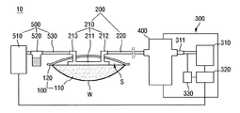
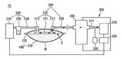
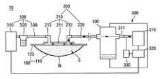
図1を参照すれば、本発明の一実施例に係る傷治療装置10は、陰圧出力部100、陰圧伝達部200、陰圧発生部300、キャニスター400および投薬剤供給部500を含む。 Referring to FIG. 1, a
図1に図示された通り、陰圧出力部100は、傷部位Wに配置され、傷部位Wを密閉させる役割をする。説明の便宜のために本発明の一実施例で傷部位Wは凹んだ開放型傷を例にして説明するが、これに限定されるものではない。 As shown in FIG. 1, the negative
陰圧出力部100は開放型傷部位Wに配置されるフォームドレッシング110と、傷部位を密閉するフィルムドレッシング120を含む。 The negative
フォームドレッシング110は、傷部位Wに配置され、陰圧によって傷から発生する滲出物を吸収する役割を遂行する。 The
フォームドレッシング110は、傷で発生した滲出物を効率的に排出するために、ポリウレタン、ポリエーテルなどの材質からなり得るが、これに限定されず、滲出物を効果的に排出できる材質であれば充分である。例えば、フォームドレッシング110が疏水性材質であるポリウレタン材質からなる場合、容易に滲出物を外部に排出することができる。 The
また、フォームドレッシング110は傷(W)に陰圧を分配し、傷から引っ張られた流体(滲出物など)を伝達できる通孔(pores)を含むことができる。例えば、フォームドレッシング110は滲出物を効率的に排出できるオープンセル網成形構造などで構成され得る。 The
また、フォームドレッシング110は、陰圧発生部300で供給された陰圧によって体積が可変され得る。例えば、フォームドレッシング110は後述するように、フィルムドレッシング120と傷部位Wの間に形成された密閉空間Sに陰圧が供給される時、陰圧によって体積が縮小されながら傷部位Wの表面に圧着される。また、フォームドレッシング120は密閉空間Sに陰圧供給が中止される場合、復原力によって縮小された体積が元の状態に戻ることになる。これに伴い、フォームドレッシング110は陰圧によって体積が可変され得る。 In addition, the volume of the foam dressing 110 can be changed by the negative pressure supplied from the
フィルムドレッシング120は、傷部位Wに隣接した皮膚に付着して、傷部位Wを密閉する役割を遂行する。図1に図示された通り、フィルムドレッシング120は、後述した吸入ヘッド210の一部を除いて傷部位Wを密閉する。 The film dressing 120 adheres to the skin adjacent to the wound site W and seals the wound site W. As shown in FIG. 1, the film dressing 120 seals the wound site W except for a part of an
フィルムドレッシング120が傷部位Wに隣接した皮膚に付着することによって、フィルムドレッシング120は、傷部位Wとともに密閉空間が形成される。 By the film dressing 120 adhering to the skin adjacent to the wound site W, the film dressing 120 forms a closed space together with the wound site W.
フィルムドレッシング120は伸縮性を有する材質で形成される。これに伴い、フィルムドレッシング120は密閉空間S内の圧力が変化する時、密閉空間S内の圧力変化によって破れるか破綻されなくなる。 The film dressing 120 is made of a stretchable material. Accordingly, when the pressure in the closed space S changes, the film dressing 120 does not break or fail due to the pressure change in the closed space S.
陰圧伝達部200は陰圧発生部300で生成された陰圧を陰圧出力部100に伝達する役割を遂行する。 The
図1に図示された通り、陰圧伝達部200は、フォームドレッシング110の一側面と連結される吸入ヘッド210と、吸入ヘッド210と陰圧発生部300を連通させるドレーンチューブ220を含む。 As shown in FIG. 1, the negative
吸入ヘッド210は陰圧によってフォームドレッシング110に吸収された滲出物をドレーンチューブ220に案内する役割を遂行する。また、本発明の一実施例で吸入ヘッド220は、後述するように投薬剤供給部500の連結チューブ530から投薬剤を供給受けて傷部位Wに投与する役割も遂行できる。 The
吸入ヘッド210は、フォームドレッシング110の一側面と連結されるフランジ部211、ドレーンチューブ220と連結される第1連結管部212および連結チューブ530と連結される第2連結管部213を含む。 The
フランジ部211は第1連結管部212および第2連結管部213のうち少なくともいずれか一つと連結される複数の案内流路(図示されず)が形成される。フランジ部211は複数の案内流路を通じてフォームドレッシング110に吸収された滲出物を第1連結管部212に案内する。また、フランジ部211は第2連結管部213を通じて投薬剤供給部500で供給された投薬剤を複数の案内流路を通じて傷部位Wに均一に注入する。 The
ドレーンチューブ220の一端は第1連結管部212と連結される。これに伴い、ドレーンチューブ220は吸入ヘッド210を通じて密閉空間Sと間接的に連通することができる。所定の実施例で吸入ヘッド210は省略され得、この場合、ドレーンチューブ220の一端はフィルムドレッシング120を貫通して密閉空間Sと直接的に連通することができる。 One end of the
また、ドレーンチューブ220の他端はキャニスター400と連結される。後述するように、キャニスター400は陰圧発生ユニット310の出力端312と連結されているため、ドレーンチューブ220はキャニスター400を通じて陰圧発生ユニット310と間接的に連通する。 The other end of the
ドレーンチューブ220が密閉空間Sと陰圧発生ユニット310と連通するため、ドレーンチューブ220は、陰圧発生ユニット310で生成された陰圧を密閉空間Sに供給することができる。 Since the
図1に図示された通り、陰圧発生部300は陰圧を生成する陰圧発生ユニット310、陰圧発生ユニット310を制御する制御部320および陰圧発生ユニット310で出力される陰圧を感知する圧力センサ330を含む。 As shown in FIG. 1, the negative
陰圧発生部300は内部に陰圧発生ユニット310を具備し、陰圧発生ユニット310によって生成された陰圧を陰圧伝達部200を通じて陰圧出力部100に供給する。 The negative
陰圧発生ユニット310は、陰圧を生成し、ドレーンチューブ220を通じて密閉空間Sに供給する役割をする。例えば、陰圧発生ユニット310は内部に陰圧モーター(図示されず)を具備し、陰圧モーターによって生成された陰圧をドレーンチューブ220を通じて密閉空間Sに供給する。 The negative
また、陰圧発生ユニット310は制御部320によって作動が制御される。例えば、陰圧発生ユニット310は制御部320によって、陰圧モーターの駆動の有無、陰圧モーターの駆動時間、陰圧モーターで生成する陰圧の大きさなどが制御され得る。 The operation of the negative
陰圧発生ユニット310によって形成された陰圧は出力端312を通じて陰圧伝達部200のドレーンチューブ220に提供される。図1に図示された通り、出力端312はキャニスター400の他方と連結される。これに伴い、出力端312で提供される陰圧はキャニスター400を通じてキャニスター400の一側と連結されたドレーンチューブ220に提供される。 The negative pressure generated by the negative
また、陰圧発生ユニット310の出力端312には圧力センサ330が連結される。 The
圧力センサ330は密閉空間S内の圧力を感知する役割を遂行する。例えば、圧力センサ330は出力端312側の圧力を感知する。出力端312、キャニスター400、陰圧伝達部200のドレーンチューブ220および密閉空間Sは連結された空間を形成するため、出力端312で感知された圧力情報で密閉空間S内の圧力情報を把握することができる。 The
制御部320は陰圧発生ユニット310と後述する投薬剤供給部500のイリゲーションユニット510を制御する役割を遂行する。制御部320に対する詳しい事項は後述する。 The
図1に図示されてはいないが、陰圧発生部300はキャニスター400と陰圧発生ユニット310の出力端312の間に疏水性フィルタ(図示されず)が具備され得る。疏水性フィルターは密閉空間Sから排出される滲出物などの液体が陰圧発生ユニット310に流入することを防止する役割を遂行する。 Although not shown in FIG. 1, the negative
図1に図示されてはいないが、陰圧発生部300は陰圧発生部300をオン/オフ制御する電源ボタン(図示されず)が具備され得る。電源ボタンをオン(ON)とする場合、制御部320には陰圧発生ユニット310を作動させる作動信号が入力される。また、電源ボタンをオフ(OFF)とする場合、制御部320には陰圧発生ユニット310の作動を停止させる作動停止信号が入力される。 Although not shown in FIG. 1, the
図1に図示されてはいないが、陰圧発生部300は陰圧によって密閉空間Sから排出される流体の流量を測定する流量センサ(図示されず)をさらに含むことができる。流量センサーはキャニスター400と陰圧発生ユニット310の間に配置され得る。 Although not shown in FIG. 1, the
例えば、流量センサーは後述する陰圧発生ユニット310の出力端312と連結され得る。これに伴い、流量センサーはキャニスター400を通過して圧力発生ユニット310に移動する流体の流量を測定することができる。 For example, the flow rate sensor may be connected to the output end 312 of the negative
密閉空間Sから排出される流体は密閉空間S内の気体および/または液体を含む。密閉空間S内の液体は傷部位Wで発生した滲出物を含むことができる。 The fluid discharged from the closed space S includes gas and/or liquid in the closed space S. The liquid in the closed space S may include exudates generated at the wound site W.
密閉空間から排出される流体は陰圧伝達部200を通じてキャニスター400に流動することになる。キャニスター400に流動した流体のうちほとんどの液体は重力によってキャニスター400に収容され、ほとんどの気体は陰圧によって陰圧発生ユニット310に流動することになる。 The fluid discharged from the closed space flows into the
これによって、陰圧伝達部200と陰圧発生ユニット310の間に配置された流量センサ(図示されず)は密閉空間S内の気体の流量を測定することができ、流量センサーで測定された流量情報は制御部320に伝達される。 Accordingly, the flow rate sensor (not shown) disposed between the negative
投薬剤供給部500は、密閉された傷部位Wに投薬剤を注入し、傷部位Wの治療を促進させる役割をする。また、投薬剤供給部500は、イリゲーションユニット510、酸素供給ユニット520および連結チューブ530を含む。 The
傷部位Wに注入される投薬剤は精製水、殺菌数などの水などを含むことができる。また、投薬剤には傷部位Wの治療を促進する治療剤がさらに含まれ得る。また、投薬剤は酸素供給ユニット520から酸素の供給を受けて、酸素を含むことができる。 The medication injected into the wound site W may include purified water, water such as sterilization number, and the like. In addition, the medication may further include a therapeutic agent that promotes treatment of the wound site W. Further, the medication may be supplied with oxygen from the
傷部位Wに注入された投薬剤は傷部位Wを洗浄し、陰圧発生部300で供給された陰圧によって外部に排出される。これに伴い、投薬剤は傷部位Wの感染菌などを除去する役割を遂行することができる。 The drug injected into the wound site W cleans the wound site W and is discharged to the outside by the negative pressure supplied by the negative
イリゲーションユニット510は内部に所定量の投薬剤を収容するか投薬剤が貯蔵された別途の貯蔵容器から投薬剤が供給され得る。 The
イリゲーションユニット510は傷部位Wに投薬剤を供給する役割を遂行する。例えば、イリゲーションユニット510は、制御部320の制御によって電子バルブ(図示されず)を開放して投薬剤が傷部位Wに注入されるようにすることができる。それだけでなく、イリゲーションユニット510は制御部320の制御によって電子ペルプを閉鎖して傷部位Wに注入される投薬剤の注入を中止することができる。 The
ただし、所定の実施例でイリゲーションユニット510はポンプ(図示されず)を具備することができる。イリゲーションユニット510は制御部320の制御によってポンプを駆動して、投薬剤を傷部位Wに注入することができる。それだけでなく、イリゲーションユニット510は制御部320の制御によってポンプの駆動を停止して、傷部位Wに注入される投薬剤の注入を中止することができる。 However, in certain embodiments the
また、イリゲーションユニット510は吸入ヘッド210の第2連結管部213と連結された連結チューブ530に連結される。これに伴い、イリゲーションユニット510は連結チューブ530を通じて投薬剤を傷部位Wに供給することができる。 Also, the
また、イリゲーションユニット510は制御部320の制御によって投薬剤を前記傷部位Wの体積以下で注入させることができる。 Further, the
酸素供給ユニット520は傷部位Wに供給される投薬剤に酸素を供給する役割を遂行する。例えば、酸素供給ユニット520は連結チューブ530上に配置され、連結チューブ530内を流動する投薬剤に酸素を供給することができる。 The
また、酸素供給ユニット520は制御部320の制御によって傷部位Wに投薬剤が注入される時にのみ投薬剤に酸素を供給することができる。例えば、酸素供給ユニット520は投薬剤の注入と同時に作動して、投薬剤に酸素を供給することができる。 Further, the
連結チューブ530はイリゲーションユニット510と吸入ヘッド210の第2連結管213を連結する。これによって、連結チューブ530は、イリゲーションユニット510の投薬剤を傷部位Wに伝達する役割を遂行する。 The
本発明の一実施例において、投薬剤供給部500の連結チューブ530が吸入ヘッド210の第2連結管部213に連結されるにつれて、イリゲーションユニット510は吸入ヘッド210を経由して傷部位Wに投薬剤を注入する。 In one embodiment of the present invention, as the
ただし、所定の実施例で投薬剤供給部500は密閉空間S内に配置され、連結チューブと連結された別途の注入ヘッド(図示されず)をさらに含む。また、イリゲーションユニット510は別途の注入ヘッドを経由して傷部位Wに投薬剤を注入することができる。 However, in a predetermined embodiment, the
図1に図示された通り、陰圧発生部300とイリゲーションユニット510が別個のユニットで相互離隔して構成される場合には、陰圧発生部300とイリゲーションユニット510はそれぞれ制御信号を送受信する通信部(図示されず)を含むことができる。 As shown in FIG. 1, when the
それぞれの通信部は図1に図示された通り、陰圧発生部300とイリゲーションユニット510を連結する有線ケーブル(図示されず)を通じて電気的に連結されて制御部320とイリゲーションユニット510の間の制御信号を送受信することができる。 As shown in FIG. 1, each communication unit is electrically connected through a cable (not shown) that connects the
または、図示されていないが、それぞれの通信部はブルートゥース(登録商標)、Wi−Fiなどの近距離無線通信モジュールを含み、制御部320とイリゲーションユニット510の間の制御信号を無線で送受信するように構成することもできる。 Alternatively, although not shown, each communication unit includes a short-range wireless communication module such as Bluetooth (registered trademark) or Wi-Fi, and wirelessly transmits/receives a control signal between the
以下、制御部320に対する詳しい事項を説明する。制御部320は、密閉空間Sの圧力が目標陰圧に到達するように陰圧発生ユニット310を制御することができる。 The details of the
また、制御部320は密閉空間Sの圧力が目標陰圧に到達した後に、第1設定時間(t1〜t2、図7参照)の間、密閉空間Sの圧力が目標陰圧に維持されるように陰圧発生ユニット310を制御することができる。 Moreover, after the pressure of the closed space S reaches the target negative pressure, the
制御部320は第1設定時間(t1〜t2)の経過後に第2設定時間(t2〜t3)の間、密閉空間Sへの陰圧の供給が中止されるように陰圧発生装置310を制御することができる。 The
制御部320は投薬剤が第2設定時間(t2〜t3)内に注入されるようにイリゲーションユニット510を制御することができる。 The
また、制御部320は密閉空間Sへの陰圧の供給中止と同時に傷部位Wに投薬剤が注入されるようにイリゲーションユニット510を制御することができる。陰圧の供給中止と同時に傷部位Wに投薬剤を注入させることによって、投薬剤を密閉空間S内の陰圧によって容易に傷部位Wに注入させることができる。 In addition, the
例えば、密閉空間Sへの陰圧の供給が中止される時、密閉空間S内の圧力は概略最低圧力である目標陰圧(P1、図7参照)となり、密閉空間Sへの陰圧の供給が中止された以後の密閉空間S内の圧力は概略大気圧(P0)に増圧される。 For example, when the supply of the negative pressure to the closed space S is stopped, the pressure in the closed space S becomes a target negative pressure (P1, see FIG. 7) which is a substantially minimum pressure, and the negative pressure is supplied to the closed space S. The pressure in the closed space S after the stop is increased to approximately atmospheric pressure (P0).
これによって、密閉空間Sへの陰圧の供給中止と同時に投薬剤を傷部位Wに注入する場合、投薬剤を密閉空間S内の圧力によって素早く傷部位Wに注入することができる。 Accordingly, when the drug is injected into the wound site W at the same time as the supply of the negative pressure to the sealed space S is stopped, the drug can be quickly injected into the wound site W by the pressure in the sealed space S.
また、投薬剤が陰圧の供給中止と同時に傷部位Wに注入されることによって、投薬剤は第2設定時間(t2〜t3)より多くの時間の間傷部位Wと接触状態を維持することができる。 In addition, the medication is injected into the wound site W at the same time as the supply of the negative pressure is stopped, so that the medication remains in contact with the wound site W for a time longer than the second set time (t2 to t3). You can
投薬剤と傷部位Wの接触状態が所定時間の間維持されることによって、投薬剤が傷部位Wの感染菌の洗浄などをする時間を確保することができる。ただし、第2設定時間(t2〜t3)が長く形成される時、投薬剤が傷部位Wの接触状態を維持する時間が長く形成されて、傷部位Wがただれるか、傷部位で生成される肉芽組織が損傷する可能性がある。 By maintaining the contact state between the medication and the wound site W for a predetermined time, it is possible to secure a time for the medication to wash the wound site W with infectious bacteria. However, when the second set time (t2 to t3) is formed for a long time, the drug is kept in contact with the wound site W for a long time, and the wound site W breaks or is generated at the wound site. The granulation tissue may be damaged.
したがって、第2設定時間(t2〜t3)は概略2分(min)となるように設定され得るが、これは一つの例示に過ぎず、第2設定時間(t2〜t3)は傷の大きさ、傷の具合などによって変更され得る。 Therefore, the second set time (t2 to t3) may be set to be approximately 2 minutes (min), but this is only an example, and the second set time (t2 to t3) is the size of the wound. , It may be changed depending on the condition of the wound.
また、第1設定時間(t1〜t2)は第2設定時間(t2〜t3)より長く形成され得る。密閉空間Sに陰圧を供給するのは傷部位Wで発生した滲出物を外部に排出することを主目的とする。すなわち、陰圧の供給は滲出物の排出による傷部位の治療を目的とする。これに反し、傷部位Wに投薬剤を注入するのは傷部位Wを洗浄して傷部位Wにある感染菌を除去することを主目的とする。 In addition, the first set time (t1 to t2) may be formed longer than the second set time (t2 to t3). The main purpose of supplying the negative pressure to the closed space S is to discharge the exudate generated at the wound site W to the outside. That is, the supply of negative pressure is intended to treat the wound site by exudate discharge. On the contrary, the purpose of injecting the drug to the wound site W is mainly to wash the wound site W to remove the infectious bacteria at the wound site W.
したがって、傷治療時間に対応する第1設定時間(t1〜t2)が傷洗浄時間に対応する第2設定時間(t2〜t3)より長く形成されることが好ましいであろう。例えば、第1設定時間(t1〜t2)は約13分と設定され、第2設定時間(t2〜t3)は約2分と設定され得る。 Therefore, it is preferable that the first set time (t1 to t2) corresponding to the wound treatment time is formed longer than the second set time (t2 to t3) corresponding to the wound cleaning time. For example, the first set time (t1 to t2) may be set to about 13 minutes and the second set time (t2 to t3) may be set to about 2 minutes.
また、制御部320は第2設定期間(t2〜t3)内に傷部位Wへの投薬剤の注入が中止されるようにイリゲーションユニット510を制御することができる。これによって、傷部位Wには投薬剤の注入と投薬剤の排出が異なる時間に発生する可能性がある。 In addition, the
ただし、所定の実施例で制御部320は第2設定期間(t2〜t3)の経過後、傷部位Wに投薬剤の注入が中止されるようにイリゲーションユニット510を制御することができる。したがって、傷部位Wには投薬剤の注入と排出が同時に発生する時間を含む。 However, in a predetermined embodiment, the
制御部320は第2設定時間(t2〜t3)の経過後に電源ボタンのオフ(OFF)などによる作動中止信号が入力されたかを判断する。制御部320は作動中止信号が入力されない場合、密閉空間Sに陰圧が供給されるように陰圧発生ユニット310を制御することができる。言い換えれば、制御部320は作動中止信号が入力されない場合、陰圧発生ユニット310を再び作動させる。 The
制御部320は第2設定時間(t2〜t3)の経過後に密閉空間Sに陰圧を供給することによって、傷部位Wに注入された投薬剤、傷部位Wで発生した滲出物などの流体をキャニスター400に排出することができる。 The
それだけでなく、制御部320は再び密閉空間Sへの圧力が目標陰圧(P1)に到達するように陰圧発生ユニット310を制御する。 In addition, the
また、制御部320はイリゲーションユニット510を制御するために制御信号を生成する。制御部320で生成された制御信号には投薬剤供給信号および投薬剤供給中止信号などを含むことができる。制御部320で生成された信号は前述した通信部を通じてイリゲーションユニット510に伝送される。 In addition, the
また、制御部320は流量センサ(図示されず)で測定された流体の流量に基づいて傷部位Wの体積を自動で算出する役割を遂行する。制御部320で算出された傷部位Wの体積は、傷に注入される投薬剤の注入量を決める役割をする。 Further, the
例えば、制御部320はフィルムドレッシング120およびフォームドレッシング110が傷部位Wの表面に圧着される過程で排出された流体の流量を積算して傷部位Wの体積を算出することができる。 For example, the
また、制御部320は、フィルムドレッシング120がフォームドレッシング110に圧着された時から密閉空間S内の圧力が目標陰圧に到達するまで測定された流体の流量を積算して傷部位Wの体積を算出することができる。 In addition, the
所定の実施例で制御部320はフィルムドレッシング120がフォームドレッシング110に圧着された時から密閉空間Sへの陰圧供給が中止されるまで測定された流体の流量を積算して傷部位Wの体積を算出することもできる。 In a predetermined embodiment, the
また、制御部320は、測定された流体の流量変化率が臨界変化率を超過した時点から密閉空間S内の圧力が目標陰圧に到達するまで測定された流体の流量を積算して傷部位Wの体積を算出することができる。 In addition, the
制御部320は傷部位Wの体積が算出された場合、算出された傷部位Wの体積以下に投薬剤が注入されるようにイリゲーションユニット510を自動で制御することができる。例えば、後述するように、制御部320はイリゲーションユニット510の電子バルブ(図示されず)の開閉調節またはポンプ(図示されず)の作動調節などで傷部位Wに注入される投薬剤の注入量を調節することができる。 When the volume of the wound site W is calculated, the
また、所定の実施例で制御部320は第2設定時間(t2〜t3)内に密閉空間S内の圧力が大気圧または一定圧力に到達する時、投薬剤の注入が中止されるようにイリゲーションユニット510を制御することができる。これによって、制御部320は密閉空間Sの圧力によって投薬剤の注入量を調節することができる。 In addition, in a predetermined embodiment, the
制御部320は傷部位Wに注入される投薬剤に酸素が供給されるように酸素供給ユニット520を制御することができる。例えば、制御部320は通信部を通じて酸素供給ユニット520の作動を制御することができ、本発明の一実施例で制御部320は、投薬剤の注入と同時に投薬剤に酸素が供給されるように酸素供給ユニット520を制御することができる。 The
図2は本発明の一実施例に係る傷治療装置の作動方法を図示したフローチャートである。図3〜図6は本発明の一実施例に係る傷治療装置の作動過程を概略的に図示した図面である。図7は本発明の一実施例に係る傷治療装置の作動過程で密閉空間の圧力変化を概略的に図示したグラフである。 FIG. 2 is a flowchart illustrating a method of operating a wound treatment device according to an exemplary embodiment of the present invention. 3 to 6 are views schematically illustrating an operation process of a wound treatment device according to an exemplary embodiment of the present invention. FIG. 7 is a graph schematically showing a pressure change in a closed space during an operation process of a wound treatment device according to an exemplary embodiment of the present invention.
図2〜図7を参照すれば、まず、治療者が患者の傷部位(W、図3参照)にフォームドレッシング(110、図3参照)を配置する(S10)。傷部位Wに配置されたフォームドレッシング110は傷部位Wで発生する滲出物を吸収する。 Referring to FIGS. 2 to 7, first, the therapist places the foam dressing (110, see FIG. 3) on the wound site (W, see FIG. 3) of the patient (S10). The
図3に図示された通り、傷部位Wにフォームドレッシング110を配置した後、治療者は傷部位Wに隣接した皮膚にフィルムドレッシング(120、図3参照)を付着して、傷部位Wを密閉する(S20)。これによって、フィルムドレッシング120および傷部位Wの間には密閉空間(S、図1参照)が形成される。 As shown in FIG. 3, after placing the foam dressing 110 on the wound site W, the therapist attaches a film dressing (120, see FIG. 3) to the skin adjacent to the wound site W to seal the wound site W. Yes (S20). As a result, a closed space (S, see FIG. 1) is formed between the film dressing 120 and the wound site W.
傷部位Wが密閉された後、治療者は陰圧発生ユニット(310、図1参照)を作動させて前記密閉空間Sに陰圧発生ユニット310で生成された陰圧を供給する(S30)。これによって、密閉空間Sの圧力は陰圧発生ユニット310で供給された陰圧によって大気圧(P0、図7参照)から目標陰圧(P1、図7参照)に減圧される。 After the wound site W is sealed, the therapist operates the negative pressure generation unit (310, see FIG. 1) to supply the negative pressure generated by the negative
制御部(320、図1参照)は圧力センサ(330、図1参照)を通じて密閉空間S内の圧力を感知し、感知された密閉空間Sの圧力が目標圧力(P1、図7参照)に到達したかを判断する(S40)。 The controller (320, see FIG. 1) senses the pressure in the closed space S through the pressure sensor (330, see FIG. 1), and the detected pressure in the closed space S reaches the target pressure (P1, see FIG. 7). It is determined whether or not (S40).
ここで、目標圧力(P1)は−125mmHgまたは−125mmHgを含んだ圧力範囲に設定され得る。例えば、目標圧力(P1)は−125mmHgから+5mmHgと−5mmHgの圧力範囲に設定され得る。 Here, the target pressure (P1) can be set to -125 mmHg or a pressure range including -125 mmHg. For example, the target pressure (P1) can be set in the pressure range of -125 mmHg to +5 mmHg and -5 mmHg.
また、−125mmHgとは、大気圧より125mmHg低い圧力を意味する。また、一般に大気圧は概略760mmHgと定義され、大気圧より125mmHg低い圧力は概略635mmHgと定義される。しかし、本発明の一実施例で大気圧は0と定義され、大気圧より125mmHg低い圧力は−125mmHgと定義される。 Moreover, -125 mmHg means a pressure lower than atmospheric pressure by 125 mmHg. Further, the atmospheric pressure is generally defined as approximately 760 mmHg, and the pressure 125 mmHg lower than the atmospheric pressure is generally defined as 635 mmHg. However, in one embodiment of the present invention, the atmospheric pressure is defined as 0 and the pressure 125 mmHg lower than the atmospheric pressure is defined as -125 mmHg.
制御部320は、密閉空間S内の圧力が目標圧力(P1)に到達する時、第1設定時間(t1〜t2、図7参照)の間前記密閉空間Sの圧力を目標陰圧(P1)の一定範囲内で維持させる(S50)。 When the pressure in the closed space S reaches the target pressure (P1), the
第1設定時間(t1〜t2)は約13分(min)となるように設定され得、これは一つの例示に過ぎず、第1設定時間(t1〜t2)は傷の大きさ、傷の具合などによって変更され得る。 The first set time (t1 to t2) may be set to be about 13 minutes (min), and this is only one example, and the first set time (t1 to t2) may be the size of the wound and the size of the wound. It may be changed depending on the condition.
制御部320は、第1設定時間(t1〜t2)の間陰圧発生ユニット310のオン/オフを繰り返しながら密閉空間Sの圧力を一定範囲内で一定に維持させることができる。 The
例えば、制御部320は、密閉空間Sの圧力が既設定された目標陰圧(P1)に維持されるようにするために、陰圧発生ユニット310を作動および停止を繰り返す。言い換えれば、制御部320は、密閉空間S内の圧力が目標陰圧(P1)より高くなる場合、陰圧発生ユニット310を作動させて密閉空間S内の圧力を低くし、密閉空間S内の圧力が目標陰圧(P1)より低くなる場合、陰圧発生ユニット310の作動を停止して密閉空間S内の圧力を高くすることができる。これによって、密閉空間S内の圧力は目標陰圧(P1)に一定に維持され得る。 For example, the
ただし、制御部320は密閉空間S内の圧力が目標圧力(P1)に到達しない場合、密閉空間Sに陰圧発生ユニット310で生成された陰圧を供給するようにして、密閉空間Sの圧力が目標陰圧(P1)に到達するようにする。 However, when the pressure in the closed space S does not reach the target pressure (P1), the
また、図2には図示していないが、流量センサ(図示されず)は陰圧発生部200から密閉空間Sに供給された陰圧によって、密閉空間Sから排出される流体の流量を測定する。 Although not shown in FIG. 2, a flow rate sensor (not shown) measures the flow rate of the fluid discharged from the closed space S by the negative pressure supplied to the closed space S from the negative
流量センサーは測定された流体の流量情報を制御部320に伝達する。制御部320は流量センサーで測定された流体の流量に基づいて傷部位Wの体積を算出することができる。 The flow rate sensor transmits the measured flow rate information of the fluid to the
例えば、図4に図示された通り、制御部320はフィルムドレッシング120がフォームドレッシング110に圧着された後にも密閉空間Sに陰圧供給し続ける。これによって、図5に図示された通り、フィルムドレッシング120およびフォームドレッシング110は傷部位Wの表面に圧着される。すなわち、フィルムドレッシング120が圧着されたフォームドレッシング110は傷部位Wの表面に圧着される。 For example, as shown in FIG. 4, the
フィルムドレッシング120およびフォームドレッシング110が傷部位Wの表面に圧着される過程においても密閉空間内の流体が排出される。フォームドレッシング110は傷部位Wに配置されるので、フィルムドレッシング120およびフォームドレッシング110が圧着される過程で排出される流体の量は概略傷部位の体積に対応され得る。 The fluid in the closed space is discharged even in the process of pressing the film dressing 120 and the foam dressing 110 onto the surface of the wound site W. Since the foam dressing 110 is disposed on the wound site W, the amount of fluid discharged during the process of pressing the film dressing 120 and the foam dressing 110 can roughly correspond to the volume of the wound site.
これによって、制御部320はフィルムドレッシング120およびフォームドレッシング110が傷部位Wの表面に圧着される過程で排出される流体の流量を積算する場合、傷部位Wの体積を算出することができる。 Accordingly, the
また、図3に図示された通り、フィルムドレッシング120がフォームドレッシング110に圧着される過程では、陰圧の抵抗力でフィルムドレッシング130の引張り力などが作用するようになる。 In addition, as shown in FIG. 3, in the process in which the film dressing 120 is pressed against the foam dressing 110, the pulling force of the film dressing 130 acts due to the resistance of negative pressure.
しかし、図4および図5に図示された通り、フィルムドレッシング120およびフォームドレッシング110が傷部位Wの表面に圧着される過程では陰圧の抵抗力でフィルムドレッシング130の引張り力およびフォームドレッシング110の圧縮力などが作用するようになる。 However, as shown in FIGS. 4 and 5, in the process in which the film dressing 120 and the foam dressing 110 are pressed against the surface of the wound site W, the pulling force of the film dressing 130 and the compression of the foam dressing 110 due to the negative pressure resistance force. Power etc. will come into play.
フィルムドレッシング120およびフォームドレッシング110が傷部位Wの表面に圧着される過程の陰圧の抵抗力がフィルムドレッシング120がフォームドレッシング110に圧着される過程の陰圧の抵抗力より大きいので、フィルムドレッシング120およびフォームドレッシング110が傷部位Wの表面に圧着される過程で排出される流体の流量はフィルムドレッシング120がフォームドレッシング110に圧着される過程で排出される流体の流量より小さく形成される。したがって、密閉空間Sから排出される流体の流量は大きく変化するようになる。 Since the negative pressure resistance in the process of pressing the film dressing 120 and the foam dressing 110 onto the surface of the wound site W is larger than the negative pressure resistance in the process of pressing the film dressing 120 onto the foam dressing 110, the film dressing 120 Also, the flow rate of the fluid discharged when the foam dressing 110 is pressed against the surface of the wound site W is smaller than the flow rate of the fluid discharged when the film dressing 120 is pressed against the
したがって、制御部320は流量センサ(図示されず)で測定された流体の流量変化率が既設定された臨界変化率を超過した時点から測定された流体の流量を積算して傷部位Wの体積を算出することができる。 Therefore, the
例えば、制御部320は流体の流量変化率が臨界変化率を超過した時点から密閉空間内の圧力が目標陰圧に到達した時まで測定された流量の流量を積算して傷部位Wの体積を算出することができる。 For example, the
また、所定の実施例で制御部320は流体の流量変化率が臨界変化率を超過した時点から陰圧発生ユニット310の駆動が止まる時点(密閉空間内の圧力が目標陰圧に到達した時から第1設定期間の間)まで測定された流体の流量を積算して傷部位Wの体積を算出することもできる。 Also, in a predetermined embodiment, the
制御部320は第1設定時間(t1〜t2)の経過後、第2設定時間(t2〜t3、図7参照)の間密閉空間Sに陰圧発生ユニットに310で生成された陰圧の供給を中止させる(S60)。 The
第2設定時間(t2〜t3)は概略2分(min)となるように設定され得るが、これは一つの例示に過ぎず、第2設定時間(t2〜t3)は傷の大きさ、傷の具合などによって変更され得る。 The second set time (t2 to t3) may be set to be approximately 2 minutes (min), but this is only one example, and the second set time (t2 to t3) is the size of the scratch and the scratch. It can be changed depending on the condition.
また、図6に図示された通り、制御部320は第2設定時間(t2〜t3)内に傷部位Wに投薬剤が注入されるようにイリゲーションユニット(510、図1参照)を制御する(S70)。 Further, as shown in FIG. 6, the
制御部320は密閉空間Sへの陰圧の供給中止と同時に投薬剤が傷部位Wに注入されるようにイリゲーションユニット510を制御することができる。これによって、密閉空間Sへの陰圧の供給中止と傷部位Wへの投薬剤の注入間にはインターバル(interval)が無いようにして、傷治療の効率性を向上させることができる。 The
陰圧の供給中止と同時に投薬剤が注入される場合、投薬剤は第2設定時間(t2〜t3)より多い時間の間傷部位Wと接触状態を維持することができる。 When the medication is injected at the same time as the supply of the negative pressure is stopped, the medication can maintain contact with the wound site W for a time longer than the second set time (t2 to t3).
また、制御部320は算出された傷部位Wの体積以下に投薬剤が注入されるようにイリゲーションユニット510を制御することができる。 In addition, the
第2設定時間(t2〜t3)の経過後、制御部320は陰圧発生部300の陰圧発生ユニット310の作動を停止させる作動停止信号が入力されたかを判断する(S80)。 After the elapse of the second set time (t2 to t3), the
制御部320は作動停止信号が入力されない場合、陰圧発生装置310を再び作動させて、密閉空間Sに陰圧を再び供給する。すなわち、制御部320は第2設定時間(t2〜t3)の経過後、密閉空間Sの圧力を目標陰圧に到達させる段階を再遂行することができる。これによって、前述した過程は前述した作動停止信号が入力される前まで継続して繰り返され得る。 When the operation stop signal is not input, the
密閉空間Sに陰圧が再び供給されることによって、傷部位Wに注入された投薬剤はキャニスター400に排出され得る。制御部320は第2設定時間(t2〜t3)内に傷部位Wへの投薬剤の注入が中止されるようにイリゲーションユニット510を制御することができる。この場合、傷部位Wには投薬剤の注入と投薬剤の排出が異なる時間に発生する可能性がある。 By supplying negative pressure to the closed space S again, the medication injected into the wound site W can be discharged to the
ただし、前述した通り、制御部320が第2設定時間(t2〜t3)の経過後、傷部位Wに投薬剤の注入が中止されるようにイリゲーションユニット510を制御する場合、傷部位Wには投薬剤の注入と排出が同時に発生する時間を含むことができる。 However, as described above, when the
また、密閉空間Sに陰圧供給から傷部位Wに投薬剤を注入する過程は一つのサイクルからなる。したがって、所定の実施例では、作動停止信号の入力がなくても既設定されたサイクル回数だけ継続して繰り返された後、陰圧発生部300の作動を停止することができる。 Also, the process of injecting the drug into the wound space W from the negative pressure supply to the closed space S consists of one cycle. Therefore, in the predetermined embodiment, even if the operation stop signal is not input, the operation of the negative
以上では本発明の好ましい実施例について図示して説明したが、本発明は前述した特定の実施例に限定されず、特許請求の範囲で請求する本発明の要旨を逸脱することなく、当該発明が属する技術分野で通常の知識を有した者によって多様な変形実施が可能であることはもちろん、このような変形実施は本発明の技術的思想や展望から個別的に理解されてはならない。 Although the preferred embodiments of the present invention have been illustrated and described above, the present invention is not limited to the specific embodiments described above, and the present invention can be implemented without departing from the gist of the present invention claimed in the scope of claims. Various modifications can be made by a person having ordinary knowledge in the technical field to which the technology belongs, and such modifications should not be individually understood from the technical idea and perspective of the present invention.
本発明の実施例に係る傷治療方法は、傷部位にフォームドレッシングを配置する段階、前記傷部位に隣接した皮膚にフィルムドレッシングを付着して前記傷部位を密閉する段階、前記フィルムドレッシングおよび前記傷部位の間に形成される密閉空間に陰圧発生ユニットで生成された陰圧を供給して、前記密閉空間の圧力を目標陰圧に到達させる段階、第1設定時間の間前記密閉空間の圧力を前記目標陰圧に維持させる段階、前記第1設定時間の経過後、第2設定期間の間前記陰圧の供給を中止する段階、および前記第2設定時間内に前記傷部位に投薬剤を注入する段階を含む。 The method for treating wounds according to the embodiment of the present invention comprises placing foam dressing on the wound site, attaching a film dressing to the skin adjacent to the wound site and sealing the wound site, the film dressing and the wound. Supplying a negative pressure generated by a negative pressure generating unit to a closed space formed between the parts so that the pressure of the closed space reaches a target negative pressure, and a pressure of the closed space for a first set time. Is maintained at the target negative pressure, a step of stopping the supply of the negative pressure for a second setting period after the lapse of the first set time, and a medication on the wound site within the second set time. Injecting step is included.
本発明の実施例に係る傷治療装置は、傷部位に配置されたフォームドレッシング、前記傷部位に投薬剤を供給するイリゲーションユニット、前記傷部位に隣接した皮膚に付着して前記傷部位を密閉させるフィルムドレッシング、陰圧を生成して、前記フィルムドレッシングおよび前記傷部位の間に形成された密閉空間に前記陰圧を供給する陰圧発生ユニット、前記陰圧発生ユニットおよび前記密閉空間を連結し、前記陰圧発生ユニットで生成された前記陰圧を前記密閉空間に伝達する陰圧伝達部および前記陰圧発生ユニットと前記イリゲーションユニットを制御する制御部を含み、前記制御部は、前記陰圧の供給中止と同時に前記傷部位に投薬剤が注入されるように前記陰圧発生ユニットおよび前記イリゲーションユニットを制御する。 A wound treatment device according to an embodiment of the present invention includes a foam dressing disposed at a wound site, an irrigation unit that supplies a medication to the wound site, and a skin adjoining the wound site to seal the wound site. Film dressing, negative pressure generation unit that generates negative pressure and supplies the negative pressure to the sealed space formed between the film dressing and the wound site, connects the negative pressure generation unit and the sealed space, The negative pressure generating unit includes a negative pressure transmitting unit that transmits the negative pressure generated in the negative pressure generating unit to the closed space, and a controller that controls the negative pressure generating unit and the irrigation unit. The negative pressure generating unit and the irrigation unit are controlled so that the drug is injected into the wound site at the same time when the supply is stopped.
Claims (9)
Translated fromJapanese連結チューブ530を通じて前記傷部位に投薬剤を供給するイリゲーションユニット;
前記傷部位に隣接した皮膚に付着して前記傷部位を密閉させるフィルムドレッシング;
陰圧を生成して、前記フィルムドレッシング及び前記傷部位の間に形成された密閉空間に前記陰圧を供給する陰圧発生ユニット;
前記陰圧発生ユニット及び前記密閉空間を連結し、前記陰圧発生ユニットで生成された前記陰圧を前記密閉空間に伝達する陰圧伝達部;及び
前記陰圧発生ユニットと前記イリゲーションユニットを制御する制御部を含み、
前記制御部は、前記陰圧の供給中止と同時に前記傷部位に投薬剤が注入されるように前記陰圧発生ユニット及び前記イリゲーションユニットを制御し、
前記制御部は、前記流量センサーで測定された前記流体の流量に基づいて前記傷部位の体積を算出し、
前記陰圧伝達部200は、前記フォームドレッシング110の一側面と連結される吸入ヘッド210と、前記吸入ヘッド210と陰圧発生部300を連通させるドレーンチューブ220を含み、
前記吸入ヘッド210は、前記フォームドレッシング110の一側面と連結されるフランジ部211、前記ドレーンチューブ220と連結される第1連結管部212、及び前記第1連結管部212及び前記連結チューブ530と連結される第2連結管部213を含み、
前記フランジ部211は、前記第1連結管部212及び前記第2連結管部213と連結される複数の案内流路を有する、傷治療装置。Foam dressing placed on the wound site;
An irrigation unit for supplying a drug to the wound site through a connecting tube 530;
A film dressing that adheres to the skin adjacent to the wound site and seals the wound site;
A negative pressure generating unit that generates a negative pressure and supplies the negative pressure to an enclosed space formed between the film dressing and the wound site;
A negative pressure transmission unit that connects the negative pressure generation unit and the closed space and transmits the negative pressure generated by the negative pressure generation unit to the closed space; and controls the negative pressure generation unit and the irrigation unit. Including the controller,
The control unit controls the negative pressure generation unit and the irrigation unit so that a drug is injected into the wound site at the same time when the supply of the negative pressure is stopped,
The control unit calculates the volume of the wound site based on the flow rate of the fluid measured by the flow rate sensor,
The negative pressure transmitting unit 200 includes a suction head 210 connected to one side of the foam dressing 110, and a drain tube 220 connecting the suction head 210 and the negative pressure generating unit 300.
The suction head 210 includes a flange part 211 connected to one side of the foam dressing 110, a first connection pipe part 212 connected to the drain tube 220, the first connection pipe part 212 and the connection tube 530. Including a second connecting pipe portion 213 to be connected,
The wound treatment device wherein the flange portion 211 has a plurality of guide channels connected to the first connection pipe portion 212 and the second connection pipe portion 213.
前記密閉空間の圧力が目標陰圧に到達した後、第1設定時間の間前記密閉空間の圧力が前記目標陰圧に維持されるように前記陰圧発生ユニットを制御する、請求項1に記載の傷治療装置。The control unit is
The negative pressure generation unit is controlled so that the pressure in the closed space is maintained at the target negative pressure for a first set time after the pressure in the closed space reaches the target negative pressure. Wound healing device.
前記第1設定時間の経過後、第2設定時間の間前記陰圧の供給が中止されるように前記陰圧発生ユニットを制御し、前記陰圧の供給の中止と同時に前記投薬剤が注入されるように前記イリゲーションユニットを制御する、請求項2に記載の傷治療装置。The control unit is
After the lapse of the first set time, the negative pressure generation unit is controlled so that the supply of the negative pressure is stopped for a second set time, and the medication is injected at the same time as the supply of the negative pressure is stopped. The wound treatment device according to claim 2, wherein the irrigation unit is controlled so as to control the irrigation unit.
前記第2設定時間内に前記投薬剤の注入が中止されるように前記イリゲーションユニットを制御する、請求項3に記載の傷治療装置。The control unit is
4. The wound treatment device according to claim 3, wherein the irrigation unit is controlled so that the injection of the medication is stopped within the second set time.
前記第2設定時間経過後に前記投薬剤の注入が中止されるように前記イリゲーションユニットを制御する、請求項3に記載の傷治療装置。The control unit is
4. The wound treatment device according to claim 3, wherein the irrigation unit is controlled so that the injection of the medication is stopped after the second set time has elapsed.
前記制御部は、前記流量センサーで測定された前記流体の流量に基づいて前記傷部位の体積を算出する、請求項8に記載の傷治療装置。Further comprising a flow sensor for measuring a flow rate of fluid discharged from the closed space by the negative pressure,
9. The wound treatment device according to claim 8, wherein the control unit calculates the volume of the wound site based on the flow rate of the fluid measured by the flow rate sensor.
Applications Claiming Priority (2)
| Application Number | Priority Date | Filing Date | Title |
|---|---|---|---|
| KR10-2015-0033105 | 2015-03-10 | ||
| KR1020150033105AKR101637976B1 (en) | 2015-03-10 | 2015-03-10 | Method and apparatus for treating a wound |
Related Parent Applications (1)
| Application Number | Title | Priority Date | Filing Date |
|---|---|---|---|
| JP2017545599ADivisionJP2018506392A (en) | 2015-03-10 | 2016-01-19 | Wound treatment method and apparatus |
Publications (1)
| Publication Number | Publication Date |
|---|---|
| JP2020110632Atrue JP2020110632A (en) | 2020-07-27 |
Family
ID=56504662
Family Applications (2)
| Application Number | Title | Priority Date | Filing Date |
|---|---|---|---|
| JP2017545599APendingJP2018506392A (en) | 2015-03-10 | 2016-01-19 | Wound treatment method and apparatus |
| JP2020048977APendingJP2020110632A (en) | 2015-03-10 | 2020-03-19 | Wound treatment method and device |
Family Applications Before (1)
| Application Number | Title | Priority Date | Filing Date |
|---|---|---|---|
| JP2017545599APendingJP2018506392A (en) | 2015-03-10 | 2016-01-19 | Wound treatment method and apparatus |
Country Status (10)
| Country | Link |
|---|---|
| US (1) | US20180050137A1 (en) |
| EP (1) | EP3269404B1 (en) |
| JP (2) | JP2018506392A (en) |
| KR (1) | KR101637976B1 (en) |
| CN (1) | CN107889464B (en) |
| CL (1) | CL2017002228A1 (en) |
| CO (1) | CO2017008857A2 (en) |
| ES (1) | ES2843725T3 (en) |
| TW (1) | TWI597076B (en) |
| WO (1) | WO2016143997A1 (en) |
Families Citing this family (17)
| Publication number | Priority date | Publication date | Assignee | Title |
|---|---|---|---|---|
| WO2018186941A1 (en)* | 2017-04-04 | 2018-10-11 | Kci Licensing, Inc. | Apparatuses, systems, and methods for the treatment of a tissue site with negative pressure and oxygen |
| US12036353B2 (en)* | 2017-07-29 | 2024-07-16 | Edward D. Lin | Apparatus and methods for pressure management within a wound chamber |
| CN107569322A (en)* | 2017-10-18 | 2018-01-12 | 广州润虹医药科技股份有限公司 | A kind of negative-pressure wound therapeutic system |
| BR112020013463A2 (en)* | 2018-01-03 | 2020-12-01 | Cg Bio Co., Ltd. | volume measuring device, tissue expansion device, and breast volume measuring method |
| WO2019190753A1 (en)* | 2018-03-29 | 2019-10-03 | Kci Licensing, Inc. | A system for managing instillation therapy on multiple wounds with a single fluid source |
| US11141317B2 (en) | 2018-03-29 | 2021-10-12 | Kci Licensing, Inc. | Wound therapy system with wound volume estimation |
| US11040127B2 (en) | 2018-04-09 | 2021-06-22 | Kci Licensing, Inc. | Abdominal dressing with mechanism for fascial closure |
| US11701264B2 (en)* | 2018-06-27 | 2023-07-18 | Kci Licensing, Inc. | Wound therapy system with wound volume estimation using geometric approximation |
| WO2020005536A1 (en)* | 2018-06-27 | 2020-01-02 | Kci Licensing, Inc. | Wound dressing for wound volume estimation |
| CN112423800B (en)* | 2018-08-03 | 2024-05-17 | 3M创新知识产权公司 | Wound treatment system with wound volume estimation |
| EP3840794B1 (en) | 2018-08-21 | 2023-10-11 | 3M Innovative Properties Company | System for utilizing pressure decay to determine available fluid capacity in a negative pressure dressing |
| EP3873551B1 (en)* | 2018-11-02 | 2025-10-15 | Solventum Intellectual Properties Company | Wound therapy tubeset system for wound volume estimation |
| GB2579368B (en)* | 2018-11-29 | 2022-11-09 | Nexa Medical Ltd | Wound-dressing conditioning device |
| GB202001212D0 (en) | 2020-01-29 | 2020-03-11 | Smith & Nephew | Systems and methods for measuring and tracking wound volume |
| US11998651B2 (en)* | 2022-03-17 | 2024-06-04 | Becton, Dickinson And Company | Skin preparation applicator |
| CN115645259A (en)* | 2022-10-26 | 2023-01-31 | 江苏容正医药科技有限公司 | Negative-pressure low-temperature plasma wound surface treatment system, device and medium |
| WO2025084686A1 (en)* | 2023-10-19 | 2025-04-24 | (주)시지바이오 | Negative pressure therapy device and method for controlling same |
Citations (8)
| Publication number | Priority date | Publication date | Assignee | Title |
|---|---|---|---|---|
| JP2003532504A (en)* | 2000-05-09 | 2003-11-05 | ケーシーアイ ライセンシング インク | Abdominal wound dressing |
| US20030212357A1 (en)* | 2002-05-10 | 2003-11-13 | Pace Edgar Alan | Method and apparatus for treating wounds with oxygen and reduced pressure |
| JP2011508614A (en)* | 2007-12-06 | 2011-03-17 | スミス アンド ネフュー ピーエルシー | Apparatus and method for measuring wound volume |
| JP2012513824A (en)* | 2008-12-24 | 2012-06-21 | ケーシーアイ ライセンシング インコーポレイテッド | Vacuum treatment system and method using debridement mechanism |
| JP2013517096A (en)* | 2010-01-20 | 2013-05-16 | ケーシーアイ ライセンシング インク | Wound connection pad and system and method for fluid perfusion and negative pressure wound closure therapy |
| WO2013117318A1 (en)* | 2012-02-11 | 2013-08-15 | Paul Hartmann Ag | Wound therapy device |
| JP2015501170A (en)* | 2011-09-30 | 2015-01-15 | エクシジェント テクノロジーズ, エルエルシー | Electrokinetic pump wound treatment system and method |
| JP2015505266A (en)* | 2012-01-10 | 2015-02-19 | ケーシーアイ ライセンシング インコーポレイテッド | System and method for delivering fluid to a wound therapy dressing |
Family Cites Families (8)
| Publication number | Priority date | Publication date | Assignee | Title |
|---|---|---|---|---|
| US20030021775A1 (en)* | 2001-07-27 | 2003-01-30 | Ramot University Authority For Applied Research & Industrial Development Ltd. | Device for and method of controlled enzymatic removal and retrieval of tissue |
| GB0409443D0 (en)* | 2004-04-28 | 2004-06-02 | Smith & Nephew | Apparatus |
| US8057446B2 (en)* | 2007-05-01 | 2011-11-15 | The Brigham And Women's Hospital, Inc. | Wound healing device |
| WO2010051071A1 (en)* | 2008-10-29 | 2010-05-06 | Kci Licensing, Inc. | Reduced-pressure, wound-closure and treatment systems and methods |
| GB0902816D0 (en)* | 2009-02-19 | 2009-04-08 | Smith & Nephew | Fluid communication path |
| KR101063342B1 (en) | 2009-12-04 | 2011-09-07 | 주식회사 바이오알파 | Portable vacuum generator and medical suction device using same |
| JP2013515021A (en)* | 2009-12-22 | 2013-05-02 | リスホスピタレト,コペンハーゲン ユニバーシティ ホスピタル | Wound treatment products |
| EP2814532B2 (en)* | 2012-02-13 | 2020-04-15 | Integrated Healing Technologies | Multi-modal wound treatment apparatus |
- 2015
- 2015-03-10KRKR1020150033105Apatent/KR101637976B1/enactiveActive
- 2016
- 2016-01-19JPJP2017545599Apatent/JP2018506392A/enactivePending
- 2016-01-19EPEP16761884.2Apatent/EP3269404B1/enactiveActive
- 2016-01-19WOPCT/KR2016/000524patent/WO2016143997A1/ennot_activeCeased
- 2016-01-19ESES16761884Tpatent/ES2843725T3/enactiveActive
- 2016-01-19USUS15/556,637patent/US20180050137A1/ennot_activeAbandoned
- 2016-01-19CNCN201680014779.XApatent/CN107889464B/enactiveActive
- 2016-02-25TWTW105105639Apatent/TWI597076B/enactive
- 2017
- 2017-08-30COCONC2017/0008857Apatent/CO2017008857A2/enunknown
- 2017-09-04CLCL2017002228Apatent/CL2017002228A1/enunknown
- 2020
- 2020-03-19JPJP2020048977Apatent/JP2020110632A/enactivePending
Patent Citations (8)
| Publication number | Priority date | Publication date | Assignee | Title |
|---|---|---|---|---|
| JP2003532504A (en)* | 2000-05-09 | 2003-11-05 | ケーシーアイ ライセンシング インク | Abdominal wound dressing |
| US20030212357A1 (en)* | 2002-05-10 | 2003-11-13 | Pace Edgar Alan | Method and apparatus for treating wounds with oxygen and reduced pressure |
| JP2011508614A (en)* | 2007-12-06 | 2011-03-17 | スミス アンド ネフュー ピーエルシー | Apparatus and method for measuring wound volume |
| JP2012513824A (en)* | 2008-12-24 | 2012-06-21 | ケーシーアイ ライセンシング インコーポレイテッド | Vacuum treatment system and method using debridement mechanism |
| JP2013517096A (en)* | 2010-01-20 | 2013-05-16 | ケーシーアイ ライセンシング インク | Wound connection pad and system and method for fluid perfusion and negative pressure wound closure therapy |
| JP2015501170A (en)* | 2011-09-30 | 2015-01-15 | エクシジェント テクノロジーズ, エルエルシー | Electrokinetic pump wound treatment system and method |
| JP2015505266A (en)* | 2012-01-10 | 2015-02-19 | ケーシーアイ ライセンシング インコーポレイテッド | System and method for delivering fluid to a wound therapy dressing |
| WO2013117318A1 (en)* | 2012-02-11 | 2013-08-15 | Paul Hartmann Ag | Wound therapy device |
Also Published As
| Publication number | Publication date |
|---|---|
| US20180050137A1 (en) | 2018-02-22 |
| ES2843725T3 (en) | 2021-07-20 |
| EP3269404A1 (en) | 2018-01-17 |
| JP2018506392A (en) | 2018-03-08 |
| WO2016143997A1 (en) | 2016-09-15 |
| KR101637976B1 (en) | 2016-07-08 |
| CN107889464A (en) | 2018-04-06 |
| WO2016143997A9 (en) | 2016-11-10 |
| CO2017008857A2 (en) | 2017-11-10 |
| EP3269404A4 (en) | 2018-08-29 |
| TWI597076B (en) | 2017-09-01 |
| CL2017002228A1 (en) | 2018-03-16 |
| TW201632210A (en) | 2016-09-16 |
| CN107889464B (en) | 2021-01-26 |
| EP3269404B1 (en) | 2020-10-14 |
Similar Documents
| Publication | Publication Date | Title |
|---|---|---|
| JP2020110632A (en) | Wound treatment method and device | |
| KR101633497B1 (en) | A method and apparatus for measuring volum of wound | |
| CN104039286B (en) | wound healing device | |
| CA2925998C (en) | Apparatus and method for administering reduced pressure treatment to a tissue site | |
| CN101257876B (en) | Self contained wound dressing apparatus | |
| EP2242522B1 (en) | Sustained variable negative pressure wound treatment and method of controlling same | |
| KR101685509B1 (en) | Method for checking drain tube and recalculation volume of wound | |
| KR102197856B1 (en) | Medical washer with water pump and air pump | |
| US20250032697A1 (en) | Systems and methods for controlling pressure delivery by negative pressure wound therapy devices | |
| HK1198417B (en) | Wound therapy device | |
| HK1137157B (en) | Apparatus and method for administering reduced pressure treatment to a tissue site |
Legal Events
| Date | Code | Title | Description |
|---|---|---|---|
| A621 | Written request for application examination | Free format text:JAPANESE INTERMEDIATE CODE: A621 Effective date:20200319 | |
| A131 | Notification of reasons for refusal | Free format text:JAPANESE INTERMEDIATE CODE: A131 Effective date:20210216 | |
| A521 | Request for written amendment filed | Free format text:JAPANESE INTERMEDIATE CODE: A523 Effective date:20210517 | |
| A131 | Notification of reasons for refusal | Free format text:JAPANESE INTERMEDIATE CODE: A131 Effective date:20211012 | |
| A02 | Decision of refusal | Free format text:JAPANESE INTERMEDIATE CODE: A02 Effective date:20220510 |