JP2020108265A - Vehicular power supply system - Google Patents
Vehicular power supply systemDownload PDFInfo
- Publication number
- JP2020108265A JP2020108265AJP2018245011AJP2018245011AJP2020108265AJP 2020108265 AJP2020108265 AJP 2020108265AJP 2018245011 AJP2018245011 AJP 2018245011AJP 2018245011 AJP2018245011 AJP 2018245011AJP 2020108265 AJP2020108265 AJP 2020108265A
- Authority
- JP
- Japan
- Prior art keywords
- main battery
- power
- power supply
- capacitor
- coil
- Prior art date
- Legal status (The legal status is an assumption and is not a legal conclusion. Google has not performed a legal analysis and makes no representation as to the accuracy of the status listed.)
- Pending
Links
Images


Classifications
- B—PERFORMING OPERATIONS; TRANSPORTING
- B60—VEHICLES IN GENERAL
- B60L—PROPULSION OF ELECTRICALLY-PROPELLED VEHICLES; SUPPLYING ELECTRIC POWER FOR AUXILIARY EQUIPMENT OF ELECTRICALLY-PROPELLED VEHICLES; ELECTRODYNAMIC BRAKE SYSTEMS FOR VEHICLES IN GENERAL; MAGNETIC SUSPENSION OR LEVITATION FOR VEHICLES; MONITORING OPERATING VARIABLES OF ELECTRICALLY-PROPELLED VEHICLES; ELECTRIC SAFETY DEVICES FOR ELECTRICALLY-PROPELLED VEHICLES
- B60L58/00—Methods or circuit arrangements for monitoring or controlling batteries or fuel cells, specially adapted for electric vehicles
- B60L58/10—Methods or circuit arrangements for monitoring or controlling batteries or fuel cells, specially adapted for electric vehicles for monitoring or controlling batteries
- B60L58/18—Methods or circuit arrangements for monitoring or controlling batteries or fuel cells, specially adapted for electric vehicles for monitoring or controlling batteries of two or more battery modules
- B60L58/20—Methods or circuit arrangements for monitoring or controlling batteries or fuel cells, specially adapted for electric vehicles for monitoring or controlling batteries of two or more battery modules having different nominal voltages
- B—PERFORMING OPERATIONS; TRANSPORTING
- B60—VEHICLES IN GENERAL
- B60L—PROPULSION OF ELECTRICALLY-PROPELLED VEHICLES; SUPPLYING ELECTRIC POWER FOR AUXILIARY EQUIPMENT OF ELECTRICALLY-PROPELLED VEHICLES; ELECTRODYNAMIC BRAKE SYSTEMS FOR VEHICLES IN GENERAL; MAGNETIC SUSPENSION OR LEVITATION FOR VEHICLES; MONITORING OPERATING VARIABLES OF ELECTRICALLY-PROPELLED VEHICLES; ELECTRIC SAFETY DEVICES FOR ELECTRICALLY-PROPELLED VEHICLES
- B60L50/00—Electric propulsion with power supplied within the vehicle
- B60L50/50—Electric propulsion with power supplied within the vehicle using propulsion power supplied by batteries or fuel cells
- B60L50/60—Electric propulsion with power supplied within the vehicle using propulsion power supplied by batteries or fuel cells using power supplied by batteries
- B60L50/66—Arrangements of batteries
- B—PERFORMING OPERATIONS; TRANSPORTING
- B60—VEHICLES IN GENERAL
- B60L—PROPULSION OF ELECTRICALLY-PROPELLED VEHICLES; SUPPLYING ELECTRIC POWER FOR AUXILIARY EQUIPMENT OF ELECTRICALLY-PROPELLED VEHICLES; ELECTRODYNAMIC BRAKE SYSTEMS FOR VEHICLES IN GENERAL; MAGNETIC SUSPENSION OR LEVITATION FOR VEHICLES; MONITORING OPERATING VARIABLES OF ELECTRICALLY-PROPELLED VEHICLES; ELECTRIC SAFETY DEVICES FOR ELECTRICALLY-PROPELLED VEHICLES
- B60L50/00—Electric propulsion with power supplied within the vehicle
- B60L50/50—Electric propulsion with power supplied within the vehicle using propulsion power supplied by batteries or fuel cells
- B60L50/60—Electric propulsion with power supplied within the vehicle using propulsion power supplied by batteries or fuel cells using power supplied by batteries
- B—PERFORMING OPERATIONS; TRANSPORTING
- B60—VEHICLES IN GENERAL
- B60L—PROPULSION OF ELECTRICALLY-PROPELLED VEHICLES; SUPPLYING ELECTRIC POWER FOR AUXILIARY EQUIPMENT OF ELECTRICALLY-PROPELLED VEHICLES; ELECTRODYNAMIC BRAKE SYSTEMS FOR VEHICLES IN GENERAL; MAGNETIC SUSPENSION OR LEVITATION FOR VEHICLES; MONITORING OPERATING VARIABLES OF ELECTRICALLY-PROPELLED VEHICLES; ELECTRIC SAFETY DEVICES FOR ELECTRICALLY-PROPELLED VEHICLES
- B60L53/00—Methods of charging batteries, specially adapted for electric vehicles; Charging stations or on-board charging equipment therefor; Exchange of energy storage elements in electric vehicles
- B60L53/10—Methods of charging batteries, specially adapted for electric vehicles; Charging stations or on-board charging equipment therefor; Exchange of energy storage elements in electric vehicles characterised by the energy transfer between the charging station and the vehicle
- B60L53/14—Conductive energy transfer
- B60L53/16—Connectors, e.g. plugs or sockets, specially adapted for charging electric vehicles
- B—PERFORMING OPERATIONS; TRANSPORTING
- B60—VEHICLES IN GENERAL
- B60L—PROPULSION OF ELECTRICALLY-PROPELLED VEHICLES; SUPPLYING ELECTRIC POWER FOR AUXILIARY EQUIPMENT OF ELECTRICALLY-PROPELLED VEHICLES; ELECTRODYNAMIC BRAKE SYSTEMS FOR VEHICLES IN GENERAL; MAGNETIC SUSPENSION OR LEVITATION FOR VEHICLES; MONITORING OPERATING VARIABLES OF ELECTRICALLY-PROPELLED VEHICLES; ELECTRIC SAFETY DEVICES FOR ELECTRICALLY-PROPELLED VEHICLES
- B60L53/00—Methods of charging batteries, specially adapted for electric vehicles; Charging stations or on-board charging equipment therefor; Exchange of energy storage elements in electric vehicles
- B60L53/20—Methods of charging batteries, specially adapted for electric vehicles; Charging stations or on-board charging equipment therefor; Exchange of energy storage elements in electric vehicles characterised by converters located in the vehicle
- B60L53/22—Constructional details or arrangements of charging converters specially adapted for charging electric vehicles
- B—PERFORMING OPERATIONS; TRANSPORTING
- B60—VEHICLES IN GENERAL
- B60L—PROPULSION OF ELECTRICALLY-PROPELLED VEHICLES; SUPPLYING ELECTRIC POWER FOR AUXILIARY EQUIPMENT OF ELECTRICALLY-PROPELLED VEHICLES; ELECTRODYNAMIC BRAKE SYSTEMS FOR VEHICLES IN GENERAL; MAGNETIC SUSPENSION OR LEVITATION FOR VEHICLES; MONITORING OPERATING VARIABLES OF ELECTRICALLY-PROPELLED VEHICLES; ELECTRIC SAFETY DEVICES FOR ELECTRICALLY-PROPELLED VEHICLES
- B60L53/00—Methods of charging batteries, specially adapted for electric vehicles; Charging stations or on-board charging equipment therefor; Exchange of energy storage elements in electric vehicles
- B60L53/20—Methods of charging batteries, specially adapted for electric vehicles; Charging stations or on-board charging equipment therefor; Exchange of energy storage elements in electric vehicles characterised by converters located in the vehicle
- B60L53/24—Using the vehicle's propulsion converter for charging
- B—PERFORMING OPERATIONS; TRANSPORTING
- B60—VEHICLES IN GENERAL
- B60L—PROPULSION OF ELECTRICALLY-PROPELLED VEHICLES; SUPPLYING ELECTRIC POWER FOR AUXILIARY EQUIPMENT OF ELECTRICALLY-PROPELLED VEHICLES; ELECTRODYNAMIC BRAKE SYSTEMS FOR VEHICLES IN GENERAL; MAGNETIC SUSPENSION OR LEVITATION FOR VEHICLES; MONITORING OPERATING VARIABLES OF ELECTRICALLY-PROPELLED VEHICLES; ELECTRIC SAFETY DEVICES FOR ELECTRICALLY-PROPELLED VEHICLES
- B60L9/00—Electric propulsion with power supply external to the vehicle
- B60L9/16—Electric propulsion with power supply external to the vehicle using AC induction motors
- H—ELECTRICITY
- H02—GENERATION; CONVERSION OR DISTRIBUTION OF ELECTRIC POWER
- H02M—APPARATUS FOR CONVERSION BETWEEN AC AND AC, BETWEEN AC AND DC, OR BETWEEN DC AND DC, AND FOR USE WITH MAINS OR SIMILAR POWER SUPPLY SYSTEMS; CONVERSION OF DC OR AC INPUT POWER INTO SURGE OUTPUT POWER; CONTROL OR REGULATION THEREOF
- H02M7/00—Conversion of AC power input into DC power output; Conversion of DC power input into AC power output
- H02M7/42—Conversion of DC power input into AC power output without possibility of reversal
- H02M7/44—Conversion of DC power input into AC power output without possibility of reversal by static converters
- H02M7/48—Conversion of DC power input into AC power output without possibility of reversal by static converters using discharge tubes with control electrode or semiconductor devices with control electrode
- H02M7/53—Conversion of DC power input into AC power output without possibility of reversal by static converters using discharge tubes with control electrode or semiconductor devices with control electrode using devices of a triode or transistor type requiring continuous application of a control signal
- H02M7/537—Conversion of DC power input into AC power output without possibility of reversal by static converters using discharge tubes with control electrode or semiconductor devices with control electrode using devices of a triode or transistor type requiring continuous application of a control signal using semiconductor devices only, e.g. single switched pulse inverters
- H02M7/5387—Conversion of DC power input into AC power output without possibility of reversal by static converters using discharge tubes with control electrode or semiconductor devices with control electrode using devices of a triode or transistor type requiring continuous application of a control signal using semiconductor devices only, e.g. single switched pulse inverters in a bridge configuration
- H—ELECTRICITY
- H02—GENERATION; CONVERSION OR DISTRIBUTION OF ELECTRIC POWER
- H02P—CONTROL OR REGULATION OF ELECTRIC MOTORS, ELECTRIC GENERATORS OR DYNAMO-ELECTRIC CONVERTERS; CONTROLLING TRANSFORMERS, REACTORS OR CHOKE COILS
- H02P27/00—Arrangements or methods for the control of AC motors characterised by the kind of supply voltage
- H02P27/04—Arrangements or methods for the control of AC motors characterised by the kind of supply voltage using variable-frequency supply voltage, e.g. inverter or converter supply voltage
- H02P27/06—Arrangements or methods for the control of AC motors characterised by the kind of supply voltage using variable-frequency supply voltage, e.g. inverter or converter supply voltage using DC to AC converters or inverters
- B—PERFORMING OPERATIONS; TRANSPORTING
- B60—VEHICLES IN GENERAL
- B60L—PROPULSION OF ELECTRICALLY-PROPELLED VEHICLES; SUPPLYING ELECTRIC POWER FOR AUXILIARY EQUIPMENT OF ELECTRICALLY-PROPELLED VEHICLES; ELECTRODYNAMIC BRAKE SYSTEMS FOR VEHICLES IN GENERAL; MAGNETIC SUSPENSION OR LEVITATION FOR VEHICLES; MONITORING OPERATING VARIABLES OF ELECTRICALLY-PROPELLED VEHICLES; ELECTRIC SAFETY DEVICES FOR ELECTRICALLY-PROPELLED VEHICLES
- B60L2210/00—Converter types
- B60L2210/30—AC to DC converters
- B—PERFORMING OPERATIONS; TRANSPORTING
- B60—VEHICLES IN GENERAL
- B60L—PROPULSION OF ELECTRICALLY-PROPELLED VEHICLES; SUPPLYING ELECTRIC POWER FOR AUXILIARY EQUIPMENT OF ELECTRICALLY-PROPELLED VEHICLES; ELECTRODYNAMIC BRAKE SYSTEMS FOR VEHICLES IN GENERAL; MAGNETIC SUSPENSION OR LEVITATION FOR VEHICLES; MONITORING OPERATING VARIABLES OF ELECTRICALLY-PROPELLED VEHICLES; ELECTRIC SAFETY DEVICES FOR ELECTRICALLY-PROPELLED VEHICLES
- B60L2210/00—Converter types
- B60L2210/40—DC to AC converters
- B—PERFORMING OPERATIONS; TRANSPORTING
- B60—VEHICLES IN GENERAL
- B60L—PROPULSION OF ELECTRICALLY-PROPELLED VEHICLES; SUPPLYING ELECTRIC POWER FOR AUXILIARY EQUIPMENT OF ELECTRICALLY-PROPELLED VEHICLES; ELECTRODYNAMIC BRAKE SYSTEMS FOR VEHICLES IN GENERAL; MAGNETIC SUSPENSION OR LEVITATION FOR VEHICLES; MONITORING OPERATING VARIABLES OF ELECTRICALLY-PROPELLED VEHICLES; ELECTRIC SAFETY DEVICES FOR ELECTRICALLY-PROPELLED VEHICLES
- B60L2240/00—Control parameters of input or output; Target parameters
- B60L2240/40—Drive Train control parameters
- B60L2240/54—Drive Train control parameters related to batteries
- B60L2240/547—Voltage
- B—PERFORMING OPERATIONS; TRANSPORTING
- B60—VEHICLES IN GENERAL
- B60Y—INDEXING SCHEME RELATING TO ASPECTS CROSS-CUTTING VEHICLE TECHNOLOGY
- B60Y2200/00—Type of vehicle
- B60Y2200/90—Vehicles comprising electric prime movers
- B60Y2200/91—Electric vehicles
- Y—GENERAL TAGGING OF NEW TECHNOLOGICAL DEVELOPMENTS; GENERAL TAGGING OF CROSS-SECTIONAL TECHNOLOGIES SPANNING OVER SEVERAL SECTIONS OF THE IPC; TECHNICAL SUBJECTS COVERED BY FORMER USPC CROSS-REFERENCE ART COLLECTIONS [XRACs] AND DIGESTS
- Y02—TECHNOLOGIES OR APPLICATIONS FOR MITIGATION OR ADAPTATION AGAINST CLIMATE CHANGE
- Y02T—CLIMATE CHANGE MITIGATION TECHNOLOGIES RELATED TO TRANSPORTATION
- Y02T10/00—Road transport of goods or passengers
- Y02T10/60—Other road transportation technologies with climate change mitigation effect
- Y02T10/70—Energy storage systems for electromobility, e.g. batteries
- Y—GENERAL TAGGING OF NEW TECHNOLOGICAL DEVELOPMENTS; GENERAL TAGGING OF CROSS-SECTIONAL TECHNOLOGIES SPANNING OVER SEVERAL SECTIONS OF THE IPC; TECHNICAL SUBJECTS COVERED BY FORMER USPC CROSS-REFERENCE ART COLLECTIONS [XRACs] AND DIGESTS
- Y02—TECHNOLOGIES OR APPLICATIONS FOR MITIGATION OR ADAPTATION AGAINST CLIMATE CHANGE
- Y02T—CLIMATE CHANGE MITIGATION TECHNOLOGIES RELATED TO TRANSPORTATION
- Y02T10/00—Road transport of goods or passengers
- Y02T10/60—Other road transportation technologies with climate change mitigation effect
- Y02T10/7072—Electromobility specific charging systems or methods for batteries, ultracapacitors, supercapacitors or double-layer capacitors
- Y—GENERAL TAGGING OF NEW TECHNOLOGICAL DEVELOPMENTS; GENERAL TAGGING OF CROSS-SECTIONAL TECHNOLOGIES SPANNING OVER SEVERAL SECTIONS OF THE IPC; TECHNICAL SUBJECTS COVERED BY FORMER USPC CROSS-REFERENCE ART COLLECTIONS [XRACs] AND DIGESTS
- Y02—TECHNOLOGIES OR APPLICATIONS FOR MITIGATION OR ADAPTATION AGAINST CLIMATE CHANGE
- Y02T—CLIMATE CHANGE MITIGATION TECHNOLOGIES RELATED TO TRANSPORTATION
- Y02T90/00—Enabling technologies or technologies with a potential or indirect contribution to GHG emissions mitigation
- Y02T90/10—Technologies relating to charging of electric vehicles
- Y02T90/14—Plug-in electric vehicles
Landscapes
- Engineering & Computer Science (AREA)
- Power Engineering (AREA)
- Transportation (AREA)
- Mechanical Engineering (AREA)
- Life Sciences & Earth Sciences (AREA)
- Sustainable Development (AREA)
- Sustainable Energy (AREA)
- Electric Propulsion And Braking For Vehicles (AREA)
- Charge And Discharge Circuits For Batteries Or The Like (AREA)
Abstract
Translated fromJapaneseDescription
Translated fromJapanese本明細書が開示する技術は、車両用電源システムに関する。特に、車両外部の充電装置でメインバッテリを充電するための充電インレットを備えている車両用電源システムに関する。 The technology disclosed in this specification relates to a power supply system for a vehicle. In particular, the present invention relates to a vehicle power supply system including a charging inlet for charging a main battery with a charging device outside the vehicle.
電気自動車に搭載される電源システムは、メインバッテリとサブバッテリを備えていることが多い。サブバッテリの電圧はメインバッテリの電圧よりも低い。メインバッテリは、走行用のモータに電力を供給するために備えられており、サブバッテリは、オーディオやカーナビゲーション装置などの小電力機器に電力を供給するために備えられている。オーディオやカーナビゲーション装置などの小電力機器は「補機」と総称されることがある。また、補機に電力を供給するサブバッテリは、補機バッテリと称されることがある。 A power supply system mounted on an electric vehicle often includes a main battery and a sub battery. The voltage of the sub battery is lower than the voltage of the main battery. The main battery is provided for supplying electric power to a motor for traveling, and the sub battery is provided for supplying electric power to low-power devices such as audio and car navigation devices. Low-power devices such as audio and car navigation devices are sometimes collectively referred to as "auxiliaries." The sub-battery that supplies electric power to the auxiliary machine may be referred to as an auxiliary machine battery.
特許文献1に開示されている電気自動車(プラグインハイブリッド車)の電源システムは、メインバッテリの出力電力を降圧してサブバッテリを充電する電圧コンバータも備えている。なお、本明細書における「電気自動車」には、エンジンとモータを備えるプラグインハイブリッド車と、走行用モータのためのバッテリと燃料電池を備える自動車が含まれる。 The power supply system of the electric vehicle (plug-in hybrid vehicle) disclosed in
特許文献1の車両用電源システムは、車両外部の給電装置でメインバッテリを充電できるようにするために、充電インレットも備えている。 The vehicle power supply system of
後述するように、本明細書が開示する技術は、メインバッテリを含む車両用電源システムのノイズ低減に関する。車両用電源システムのノイズ低減に関する技術として、特許文献2の技術が知られている。特許文献2に開示された車両用電源システムでは、走行用のモータのコイルをLCフィルタのインダクタ要素として用いる。 As described later, the technology disclosed in the present specification relates to noise reduction of a vehicle power supply system including a main battery. The technique of
車両外部の給電装置でメインバッテリを充電している間に、ユーザがオーディオやカーナビゲーション装置などの補機を使う場合がある。補機を使っていると、サブバッテリの残量が減っていく。メインバッテリを充電している間にサブバッテリの残量が少なくなると、車両用電源システムのメインコンピュータは、電圧コンバータを起動する。そうすると、車両外部の給電装置がメインバッテリに接続されるとともに、電圧コンバータがメインバッテリに接続される。すなわち、電圧コンバータが充電インレットを介して車両外部の給電装置に電気的に接続される。このとき、電圧コンバータが発生するノイズが充電インレットを介して給電装置へ伝播する。それゆえ、自動車の電気部品が発するノイズは、車載の他の電気部品には深刻な影響を与えずとも、給電装置を介して公共電力網にノイズが伝播し、悪影響を与える可能性がある。 The user may use an auxiliary device such as an audio device or a car navigation device while the main battery is being charged by the power supply device outside the vehicle. When using an auxiliary machine, the remaining capacity of the sub battery decreases. When the remaining amount of the sub battery becomes low while the main battery is being charged, the main computer of the vehicle power supply system activates the voltage converter. Then, the power supply device outside the vehicle is connected to the main battery, and the voltage converter is connected to the main battery. That is, the voltage converter is electrically connected to the power feeding device outside the vehicle via the charging inlet. At this time, noise generated by the voltage converter propagates to the power supply device via the charging inlet. Therefore, the noise generated by the electric parts of the automobile may be adversely affected by the noise propagating to the public power grid through the power feeding device without seriously affecting other electric parts mounted on the vehicle.
給電装置へのノイズ伝播を抑制するのに、充電インレットとメインバッテリの間にノイズフィルタを備えることが考えられる。しかしながら、給電装置からメインバッテリへは充電時間短縮のために、一般的には大電流が流れるため、充電インレットに備えるノイズフィルタは、大電流に耐え得る必要がある。ノイズフィルタは、電流容量が大きいほど、体格も大きくなる。自動車の開発ではデバイスの容量増加を抑えることが重要なポイントであるから、体格の大きいフィルタの搭載は避けられる方がよい。本明細書は、フィルタの追加による体積増加を抑えつつ、電圧コンバータから充電インレット(車両外部の給電装置)へのノイズ伝播を抑制する技術を提供する。 A noise filter may be provided between the charging inlet and the main battery to suppress noise propagation to the power supply device. However, since a large current generally flows from the power supply device to the main battery in order to shorten the charging time, the noise filter provided in the charging inlet needs to be able to withstand the large current. The larger the current capacity of the noise filter, the larger the physique. Since suppressing the increase in device capacity is an important point in the development of automobiles, it is better to avoid installing a large-sized filter. The present specification provides a technique for suppressing noise propagation from a voltage converter to a charging inlet (power supply device outside the vehicle) while suppressing an increase in volume due to the addition of a filter.
車両用電源システムは、メインバッテリの出力電力を、走行用のモータの駆動電力に変換する電力変換器(インバータ)を備えている。一般に、インバータの入力端との正極と負極の間にはコンデンサが接続されている。このコンデンサは、インバータへの入力電圧を安定化させるために備えられている。あるいは、インバータが昇圧コンバータを伴う場合、コンデンサは、昇圧コンバータの部品として電気エネルギを蓄えるために備えられる場合もある。本明細書が開示する技術は、インバータの入力端に接続されているコンデンサを利用して充電インレット(外部の給電装置)へ伝わる高周波ノイズを低減する。 The vehicle power supply system includes an electric power converter (inverter) that converts the output electric power of the main battery into the driving electric power of the traveling motor. Generally, a capacitor is connected between a positive electrode and a negative electrode of the input terminal of the inverter. This capacitor is provided to stabilize the input voltage to the inverter. Alternatively, if the inverter is accompanied by a boost converter, a capacitor may be provided as a component of the boost converter to store electrical energy. The technique disclosed in the present specification reduces high-frequency noise transmitted to a charging inlet (external power supply device) by using a capacitor connected to an input terminal of an inverter.
本明細書が開示する車両用電源システムは、メインバッテリと、サブバッテリと、インバータと、コンデンサと、電圧コンバータと、充電インレットを備えている。サブバッテリの出力電圧は、メインバッテリの出力電圧よりも低い。インバータの入力端がメインバッテリに接続されており、出力端が走行用のモータに接続されている。電力変喚器は、メインバッテリの出力電力を走行用のモータの駆動電力に変換することができる。電圧コンバータは、メインバッテリとサブバッテリの間に接続されており、メインバッテリの電圧をサブバッテリの電圧まで降圧する。電圧コンバータを動作させることで、メインバッテリでサブバッテリを充電することが可能となる。充電インレットは、メインバッテリに接続されている。充電インレットは、車両外部の給電装置に接続可能である。コンデンサは、インバータの入力端の正極と負極の間に接続されている。 The vehicle power supply system disclosed in this specification includes a main battery, a sub-battery, an inverter, a capacitor, a voltage converter, and a charging inlet. The output voltage of the sub battery is lower than the output voltage of the main battery. The input end of the inverter is connected to the main battery, and the output end is connected to the traveling motor. The power converter can convert the output power of the main battery into the driving power of the traveling motor. The voltage converter is connected between the main battery and the sub battery and reduces the voltage of the main battery to the voltage of the sub battery. By operating the voltage converter, the sub battery can be charged by the main battery. The charging inlet is connected to the main battery. The charging inlet can be connected to a power supply device outside the vehicle. The capacitor is connected between the positive electrode and the negative electrode at the input end of the inverter.
本明細書が開示する車両用電源システムは、さらに、コイルを備えている。コイルは、メインバッテリと電圧コンバータの間に接続されている。コイルは、充電インレットからメインバッテリへの充電電力経路を介さずに、コンデンサに接続されている。別言すれば、コイルは、コンデンサと電圧コンバータの間に接続されている。コイルとコンデンサが高周波ノイズフィルタ(LCフィルタ)を構成し、電圧コンバータから充電インレット(車両外部の給電装置)へ伝播する高周波ノイズを低減する。 The vehicle power supply system disclosed in the present specification further includes a coil. The coil is connected between the main battery and the voltage converter. The coil is connected to the capacitor without passing through the charging power path from the charging inlet to the main battery. In other words, the coil is connected between the capacitor and the voltage converter. The coil and the capacitor form a high frequency noise filter (LC filter), and reduce high frequency noise propagating from the voltage converter to the charging inlet (power supply device outside the vehicle).
上記の構成は次の2点でフィルタの追加に起因する体格増加を抑制する。第一に、電気自動車がもともと備えていたコンデンサ(インバータのためのコンデンサ)を高周波ノイズフィルタのインダクタ要素として活用する。それゆえ、高周波フィルタ用に新たなコンデンサを追加する必要がない。第二に、コイルが、充電インレットからメインバッテリへの充電電力経路を介さずに、コンデンサに接続されている。それゆえ、充電インレットを介して車両外部の給電装置でメインバッテリを充電している間であってもコイルに大電流が流れない。すなわち、コイルの電流容量は、給電装置からメインバッテリへ流れる最大電流よりも小さくてよい。したがって、本明細書が開示する車両用電源システムは、充電インレットにノイズフィルタを備える場合と比較して、電流容量の小さいコイルを採用することができる。 The above configuration suppresses an increase in body size due to the addition of a filter in the following two points. Firstly, the capacitor that the electric vehicle originally had (the capacitor for the inverter) is used as the inductor element of the high frequency noise filter. Therefore, it is not necessary to add a new capacitor for the high frequency filter. Second, the coil is connected to the capacitor without the charging power path from the charging inlet to the main battery. Therefore, a large current does not flow in the coil even while the main battery is being charged by the power supply device outside the vehicle via the charging inlet. That is, the current capacity of the coil may be smaller than the maximum current flowing from the power supply device to the main battery. Therefore, the vehicle power supply system disclosed in the present specification can employ a coil having a smaller current capacity as compared with the case where the charging inlet is provided with the noise filter.
コイルは、コンデンサの端子に接続されていてもよい。コイルとコンデンサの間の電気経路を短くすることで、ノイズを効果的に低減することができる。 The coil may be connected to the terminals of the capacitor. Noise can be effectively reduced by shortening the electrical path between the coil and the capacitor.
コイルは、コンデンサの一方の端子を電圧コンバータに接続している正極線に接続されている第1巻線と、コンデンサの他方の端子を電圧コンバータに接続している負極線に接続されている第2巻線を備えており、第1巻線と第2巻線が同じ方向に巻回されていてもよい。そのようなコイルは、コモンモードチョークコイルと呼ばれる。コイルの第1巻線(または第2巻線)とコンデンサでLCフィルタを構成し、デファレンシャルモードノイズを抑制できる。その上、同じ方向に巻回されている第1巻線と第2巻線によってコモンモードノイズも抑制することができる。 The coil has a first winding connected to a positive line connecting one terminal of the capacitor to the voltage converter and a first winding connected to a negative line connecting the other terminal of the capacitor to the voltage converter. Two windings may be provided, and the first winding and the second winding may be wound in the same direction. Such a coil is called a common mode choke coil. An LC filter is configured with the first winding (or second winding) of the coil and the capacitor, and differential mode noise can be suppressed. Moreover, common mode noise can also be suppressed by the first winding and the second winding wound in the same direction.
本明細書が開示する車両用電源システムは、コイルと直列に接続されている抵抗をさらに備えていてもよい。コイルとコンデンサと抵抗はLCRフィルタを構成する。LCRフィルタは、より効果的に高周波ノイズを抑えることができる。 The vehicle power supply system disclosed in the present specification may further include a resistor connected in series with the coil. The coil, the capacitor and the resistor form an LCR filter. The LCR filter can suppress high frequency noise more effectively.
コイルは、コンデンサと電圧コンバータとともに1個のケースに収容されていてもよい。そうすれば、コイルを防水する専用のケースを用意する必要がない。さらに、ノイズ源である電圧コンバータと、ノイズフィルタ(コンデンサとコイル)が1個のケースに収容されていることで、ケースの外へ拡散するノイズを低減することができる。 The coil may be housed in one case together with the capacitor and the voltage converter. Then, it is not necessary to prepare a special case for waterproofing the coil. Furthermore, since the voltage converter that is the noise source and the noise filter (capacitor and coil) are housed in one case, it is possible to reduce noise that diffuses out of the case.
本明細書が開示する技術の詳細とさらなる改良は以下の「発明を実施するための形態」にて説明する。以下では、説明を簡単にするため、「車両用電源システム」を単純に「電源システム」と称する。 Details of the technology disclosed in the present specification and further improvements will be described in the following “Description of Embodiments”. Below, in order to simplify the description, the “vehicle power supply system” is simply referred to as the “power supply system”.
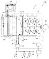
図面を参照して実施例の電源システム1を説明する。電源システム1は、電気自動車100に搭載されている。図1に、電源システム1を含む電気自動車100の電力系のブロック図を示す。電気自動車100は、電源システム1、走行用のモータ90を備えている。電源システム1は、メインバッテリ3、サブバッテリ4、インバータ10、電圧コンバータ21、コンデンサ7、コイル30、モータコントローラ22を備えている。電気自動車100は、ほかに、ナビゲーション装置93やルームランプ94などを備えている。 A
メインバッテリ3は、モータ90の駆動電力を蓄えており、その出力電圧は100ボルト以上である。 The
サブバッテリ4は、ナビゲーション装置93、ルームランプ94などの小電力機器に供給する電力を蓄えている。サブバッテリ4の出力電圧は、メインバッテリ3の出力電圧よりも低い。サブバッテリ4の出力電圧は、例えば12ボルトである。サブバッテリ4の電力で動作する機器は、補機と総称される。サブバッテリ4は、補機バッテリと呼ばれることがある。 The sub-battery 4 stores the electric power supplied to the low power equipment such as the
ナビゲーション装置93やルームランプ94などの補機は、補機電力線95を介してサブバッテリ4に接続されている。補機電力線95は、車内に張り巡らされており、様々な補機が接続されている。サブバッテリ4の負極と補機の負極はボディアースを介して接続されている。 The auxiliary devices such as the
インバータ10は、メインバッテリ3の出力電力(直流電力)を、モータ90の駆動電力(交流電力)に変換するデバイスである。インバータ10の入力端11がシステムメインリレー91を介してメインバッテリ3に接続されており、出力端12がモータ90に接続されている。システムメインリレー91は、車両のメインスイッチがオンの間、閉じられている。 The
電気自動車100のモータ90は、車両の慣性エネルギで逆駆動されることがある。モータ90は逆駆動されると発電する。モータ90の発電で得られた電力は回生電力と呼ばれる。インバータ10は、モータ90が生成した回生電力(交流電力)を直流電力に変換する機能も有している。変換された回生電力(直流電力)によってメインバッテリ3が充電される。インバータ10の出力端12から入力端11へ向けて電力が流れることがあるが、説明の便宜上、メインバッテリ3に接続されている端子を「入力端11」と称し、モータ90に接続されている端子を「出力端12」と称する。なお、メインバッテリ3とインバータ10は、第1電力線41を介して接続されている。 The
インバータ10は、直流電力を交流電力に変換するデバイスである。インバータ10は、上アームトランジスタ5aと下アームトランジスタ5bの直列接続の組を3組備えている。3組の直列接続は並列に接続されている。それぞれの直列接続の中点から交流が出力される。上アームトランジスタ5aにはダイオード6aが逆並列に接続されており、下アームトランジスタ5bにはダイオード6bが逆並列に接続されている。トランジスタ5a、5bは、モータコントローラ22により制御される。 The
インバータ10の入力端11の正極(入力端正極11a)と負極(入力端負極11b)の間には、コンデンサ7が接続されている。コンデンサ7は、メインバッテリ3とインバータ10の間に流れる電流(電圧)の脈動を抑えるために備えられている。 The
電圧コンバータ21は、メインバッテリ3とサブバッテリ4の間に接続されている。電圧コンバータ21は、メインバッテリ3の出力電圧を降圧する降圧コンバータ(ダウンコンバータ)である。電圧コンバータ21によって降圧されたメインバッテリ3の電力でサブバッテリ4が充電される。電圧コンバータ21は、第1電力線41と、第1電力線41から分岐する第2電力線42を介してメインバッテリ3に接続されている。第2電力線42は、コンデンサ7を電圧コンバータ21に接続する電力線でもある。 The
インバータ10、電圧コンバータ21、コンデンサ7、モータコントローラ22は、パワーコントロールユニット2(PCU2)として、1個のケースに収容されている。後に説明するコイル30も、同じケースに収容されている。 The
電源システム1は、システムコントローラ23を備えている。システムコントローラ23は、電源システム1を含む電気自動車100の全体を統括管理する。システムコントローラ23は、システムメインリレー91、充電リレー92、PCU2、メインバッテリ3、サブバッテリ4を管理する。 The
電源システム1は、さらに、充電インレット8を備えている。充電インレット8は、車両外部の給電装置(不図示)のコネクタを接続することができる。メインバッテリ3は、給電装置から供給される電力を使って充電される。充電インレット8は、車両のボディ(不図示)に取り付けられている。通常、充電インレット8は、カバー(不図示)で覆われており、外側からは見えない。充電インレット8は、第1電力線41と、第1電力線41から分岐している第3電力線43を介してメインバッテリ3に接続されている。第3電力線43には、充電リレー92が備えられている。充電リレー92は、走行時は開かれている。図示は省略しているが、充電インレット8に給電装置(不図示)のコネクタが接続されると、システムコントローラ23が充電リレー92を閉じるようになっている。なお、充電インレット8とメインバッテリ3の間に、別の電力変換器が接続されていてもよい。別の電力変換器は、給電装置から供給される電力を、メインバッテリ3の充電に適した電力に変換することができるデバイスである。 The
メインバッテリ3と電圧コンバータ21の間にコイル30が接続されている。コイル30は、第2電力線42の途中に接続されている。図1において一点鎖線が示す電力線の範囲は、充電インレット8からメインバッテリ3への電力経路(充電電力経路CP)を示している。図1に示されているように、コイル30は、充電インレット8からメインバッテリ3への充電電力経路CPを介さずに、コンデンサ7に電気的に接続されている。別言すれば、コイル30は、コンデンサ7と電圧コンバータ21の間に接続されている。 A
コイル30の機能について説明する。先に述べたように、電源システム1は、車両外部の給電装置からの電力でメインバッテリ3を充電することができる。給電装置は充電インレット8に接続される。充電インレット8とメインバッテリ3は、先に述べた充電電力経路CPに相当する電力線(第1電力線41の一部と第3電力線43)で接続される。一方、充電中にユーザがナビゲーション装置93やルームランプ94などの補機を使っていると、サブバッテリ4の電力が減っていく。サブバッテリ4の残電力が所定の閾値を下回ると、システムコントローラ23は、電圧コンバータ21を起動し、充電中のメインバッテリ3の電力を使ってサブバッテリ4を充電する。電圧コンバータ21が動作すると、電圧コンバータ21が発する高周波ノイズが第2電力線42、第1電力線41、第3電力線43、充電インレット8を通じて給電装置に伝わる。給電装置を介して公共電力網にノイズが伝播し、悪影響を与える可能性がある。 The function of the
図1の回路図から明らかなとおり、コイル30は、コンデンサ7との間に電気部品を挟まずに接続されており、LCフィルタを構成する。このLCフィルタが、電圧コンバータ21が発する高周波ノイズを低減する。図2に、図1の回路図に高周波ノイズの伝播経路を加えた図を示す。灰色の太実線と太破線がノイズの伝播経路を示す。太実線は、LCフィルタ(すなわち、コイル30とコンデンサ7)を通るノイズ経路を示している。太破線は、充電インレット8に到達するノイズ経路を示している。ノイズの全てがLCフィルタを通るわけではないが、ノイズの一部はLCフィルタ(コイル30とコンデンサ7)を通る。それゆえ、充電インレット8に到達するノイズ(すなわち、外部の給電装置)は低減される。 As is apparent from the circuit diagram of FIG. 1, the
上記したLCフィルタの利点を述べる。第一に、LCフィルタ専用のコンデンサを備える必要がない。LCフィルタのコンデンサ7は、インバータ10の入力端正極11aと入力端負極11bの間に接続されている。コンデンサ7は、もともと、メインバッテリ3とインバータ10の間を流れる電流(電圧)の脈動を抑える目的で備えられている。LCフィルタ以外の目的で備えられているコンデンサ7を活用することで、LCフィルタ専用のコンデンサを追加する必要がない。 The advantages of the above LC filter will be described. First, it is not necessary to provide a capacitor dedicated to the LC filter. The
第二に、充電インレット8にLCフィルタを備える場合と比較して、コイル30の電流容量は小さくてよい。充電中は、充電インレット8からメインバッテリ3へ大電流が流れている。特に、急速充電中は、充電インレット8から大電流がメインバッテリ3へ流れている。コイル30とコンデンサ7は、充電インレット8からメインバッテリ3への充電電力経路CP(図1における一点鎖線の範囲)を介さずに接続されている。それゆえ、外部の給電装置から供給される大電流はコイル30には流れない。従って、コイル30の電流容量は、充電インレット8にLCフィルタを備える場合と比較して小さくてよい。別言すれば、コイル30の電流容量は、充電インレット8を介して外部から流入し得る最大電流よりも小さくてよい。さらに別言すれば、コイル30の電流容量は、充電インレット8の電流容量よりも小さくてよい。 Secondly, the current capacity of the
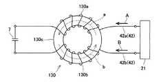
(第2実施例)図3に、第2実施例の電源システム1aを含む電気自動車100aの電力系のブロック図を示す。第2実施例の電源システム1aでは、図1のコイル30がコイル130に置き換えられている。コイル130はチョークコイルである。コイル130以外は、電源システム1aの構造は第1実施例の電源システム1と同じである。コイル130は、2本の巻線(第1巻線130a、第2巻線130b)を備えている。第1巻線130aは、コンデンサ7の一方の端子を電圧コンバータ21に接続する正極線42aに接続されている。第2巻線130bは、コンデンサ7の他方の端子を電圧コンバータ21に接続する負極線42bに接続されている。正極線42aと負極線42bが第2電力線42を構成する。第1巻線130aと第2巻線130bは、同じ方向に巻回されている。すなわち、コイル130は、コモンモードチョークコイルである。 (Second Embodiment) FIG. 3 shows a block diagram of a power system of an
図4に、コイル130の模式図を示す。第1巻線130aと第2巻線130bは、一つのコア130cに対して同じ方向に巻回されている。矢印実線Aは、正極線42aを流れるノイズの向きを示している。矢印実線Bは、負極線42bを流れるノイズの向きを示している。矢印実線Aと矢印実線Bは同じ方向を向いているので、コモンモードノイズを表している。矢印破線aは、第1巻線130aを流れるコモンモードノイズによって生じる誘導磁界の向きを示している。矢印破線bは、第2巻線130bを流れるコモンモードノイズによって生じる誘導磁界の向きを示している。 FIG. 4 shows a schematic view of the
第1巻線130aと第2巻線130bが一つのコア130cに対して同じ方向に巻回されているので、第1巻線130aによる誘導磁界(矢印破線a)と第2巻線130bによる誘導磁界(矢印破線b)は同じ向きになり、互いに強めあう。2つの誘導磁界が強めあうので、コア130cに生じるインダクタンスが大きくなる。コモンモードノイズに対するインダクタンスが大きくなるので、コモンモードノイズが抑制される。 Since the first winding 130a and the second winding 130b are wound in the same direction with respect to one
なお、第1巻線130aと第2巻線130bに互いに逆方向に流れる電流に対しては、誘導磁界が互いに逆方向となって打ち消しあう。その結果、コイル130は、第1巻線130a(正極線42a)と第2巻線130b(負極線42b)に互いに逆方向に流れる電流は、低抵抗で通過させる。 It should be noted that the induced magnetic fields cancel each other out with respect to the currents flowing through the first winding 130a and the second winding 130b in opposite directions. As a result, the
コイル130は、コンデンサ7とともにLCフィルタを構成してノイズ(特にディファレンシャルモードノイズ)を低減するとともに、コモンモードノイズを低減することができる。 The
(第3実施例)図5に、第3実施例の電源システム1bを含む電気自動車100bのブロック図を示す。第3実施例の電源システム1bの構造は、第2実施例の電源システム1aの構造と、第2電力線42の接続構造が相違する。電源システム1aと電源システム1bは、その他の構造は同じである。 (Third Embodiment) FIG. 5 shows a block diagram of an
電源システム1bでは、インバータ10の入力端正極11aがコンデンサ7の一方の端子を兼ねており、入力端負極11bがコンデンサ7他方の端子を兼ねている。そして、第2電力線42の正極線42aがコンデンサ7の一方の端子(入力端正極11a)に接続されており、第2電力線42の負極線42bがコンデンサ7の他方の端子(入力端負極11b)に接続されている。すなわち、コイル130が、コンデンサ7の端子に接続されている。コイル130とコンデンサ7の間の電気経路を短くすることで、ノイズを効果的に低減することができる。 In the
(第4実施例)図6に、第4実施例の電源システム1cを含む電気自動車100cの電力系のブロック図を示す。第4実施例の電源システム1cでは、図5のコイル130に抵抗9が直列に付加されている。電源システム1cの構造は、抵抗9を付加した以外は、第3実施例の電源システム1bと同じである。コイル130とコンデンサ7と付加された抵抗9がLCRフィルタを構成する。LCRフィルタであるので二次のローパスフィルタを実現することができる。LCRフィルタは、高周波ノイズをより強力に低減することができる。 (Fourth Embodiment) FIG. 6 shows a block diagram of a power system of an
(第5実施例)図7に、第5実施例の電源システム1dを含む電気自動車100dの電力系のブロック図を示す。第5実施例の電源システム1dでは、図1の電源システム1に対して、システムメインリレー91と充電リレー92の関係が相違する。電源システム1dの構造は、システムメインリレー91と充電リレー92の関係以外は、第1実施例の電源システム1(図1)と同じである。 (Fifth Embodiment) FIG. 7 shows a block diagram of a power system of an
第5実施例の電源システム1dでは、メインバッテリ3と充電インレット8の間にシステムメインリレー91と充電リレー92が配置されている。充電インレット8を介してメインバッテリ3を充電する場合、システムコントローラ23は、システムメインリレー91と充電リレー92の双方を閉じる(導通状態にする)。第5実施例の電源システム1dも、第1実施例の電源システム1と同様に、コイル30とコンデンサ7がLCフィルタを構成する。従って第5実施例の電源システム1dも、第1実施例の電源システム1と同じ効果を奏する。 In the
以上のとおり、実施例の電源システム1−1cは、電圧コンバータ21から充電インレット8へ伝播するノイズを低減することができる。 As described above, the power supply system 1-1c of the embodiment can reduce the noise propagating from the
(ハードウエア構造)図5に示した第3実施例の電源システム1bのPCU2のハードウエア構造について説明する。先に述べたように、インバータ10、電圧コンバータ21、コンデンサ7、モータコントローラ22、コイル130は、1個のケースに収容され、PCU2を構成する。 (Hardware Structure) The hardware structure of the
図8に、PCU2の側面図を示す。PCU2は、電気自動車1のフロントコンパートメントにて、クロスメンバ99の上に固定されている。クロスメンバ99の下方にモータハウジング96が配置されている。モータハウジング96の中にモータ90が収容されている。図中のXYZ座標系の+X方向が車両前方を示し、+Z方向が上方を示す。Y方向は車幅方向を示す。 FIG. 8 shows a side view of the
PCU2は、フロントブラケット45とリアブラケット46によって、クロスメンバ99の上に固定されている。PCU2は、上面と下面が水平となるように、クロスメンバ99の上に保持される。 The
ケース50は、基板51、インバータ10、電圧コンバータ21、コンデンサ7、コイル130を収容している。基板51に、図5に示したモータコントローラ22が実装されている。すなわち、モータコントローラ22もケース50に収容されている。 The
図9に、図8のIX−IX線に沿ってケース50をカットした断面図を示す。図9は、ケース50の後部における部品レイアウトを示している。図9では、電圧コンバータ21は途中でカットされており、電圧コンバータ21の上に配置されているコンデンサ7が見えるようにしてある。 FIG. 9 shows a sectional view of the
ケース50の後部に、コンデンサ7、電圧コンバータ21、コイル130が配置されている。符号7a、7bは、コンデンサ7の正極端子と負極端子を示している。符号21a、21bは、電圧コンバータ21の正極端子21aと負極端子21bを示している。コイル130は、コンデンサ7の端子(正極端子7a、負極端子7b)と電圧コンバータ21の端子(正極端子21a、負極端子21b)の間に配置されている。 The
図10に、コンデンサ7の斜視図を示し、図11に、コイル130の斜視図を示す。XYZ座標系の各軸の向きは、先に述べたとおりである。第1巻線130aと第2巻線130bは、樹脂製のケース60に収容されている。第1巻線130aと第2巻線130bの周囲にはポッティング材が充填されている。ケース60は、固定タブ68を備えており、固定タブ68がボルトでケース50に固定される。 FIG. 10 shows a perspective view of the
第1巻線130aの一方の端子66aに、コンデンサ側正極バスバ61が溶接され、他方の端子66bに、コンバータ側正極バスバ63が溶接される。第2巻線130bの一方の端子67aに、コンデンサ側負極バスバ62が溶接され、他方の端子67bにコンバータ側負極バスバ64が溶接される。 The capacitor side positive
コンデンサ側正極バスバ61がコンデンサ7の正極端子7aにボルトで接続される。コンデンサ側負極バスバ62がコンデンサ7の負極端子7bにボルトで接続される。コンバータ側正極バスバ63が電圧コンバータ21の正極端子21aにボルトで接続される。コンバータ側負極バスバ64が電圧コンバータ21の負極端子21bにボルトで接続される。 The capacitor-side positive
図8−図11で示したハードウエア構造の利点を説明する。高周波ノイズの発生源である電圧コンバータ21と、LCフィルタを構成するコンデンサ7とコイル130が1個のケース50に収容されている。それゆえ、ケース50から拡散するノイズを低減することができる。 The advantages of the hardware structure shown in FIGS. 8 to 11 will be described. The
コイル130は、2個の巻線(第1巻線130a、第2巻線130b)を備えている4端子構造である。すなわち、コイル130は、端子66a、67a、66b、67bを備えている。図8に示したように、4端子構造のコイル130を、コンデンサ7の端子7a、7bと電圧コンバータ21の端子21a、21bの間に配置することで、コイル130を最短距離でコンデンサ7と電圧コンバータ21に接続できる。 The
4本のバスバ61−64は、巻線130a、130bとともに、ケース60に固定されている。4本のバスバ61−64と巻線130a、130bがひとつのケース60にコンパクトにまとめられている。4本のバスバ61−64と巻線130a、130bが、1個の樹脂製のケース60にまとめられているので、絶縁性と耐震性に優れたコイルユニットが実現されている。 The four bus bars 61-64 are fixed to the
実施例で説明した技術に関する留意点を述べる。本明細書における「電気自動車」には、モータとエンジンの双方を備えるプラグインハイブリッド車と、走行用モータのためにバッテリと燃料電池を搭載している自動車が含まれる。 Points to be noted regarding the technique described in the embodiment will be described. The "electric vehicle" in the present specification includes a plug-in hybrid vehicle including both a motor and an engine, and an automobile equipped with a battery and a fuel cell for a traveling motor.
以上、本発明の具体例を詳細に説明したが、これらは例示に過ぎず、特許請求の範囲を限定するものではない。特許請求の範囲に記載の技術には、以上に例示した具体例を様々に変形、変更したものが含まれる。本明細書または図面に説明した技術要素は、単独であるいは各種の組合せによって技術的有用性を発揮するものであり、出願時請求項記載の組合せに限定されるものではない。また、本明細書または図面に例示した技術は複数目的を同時に達成し得るものであり、そのうちの一つの目的を達成すること自体で技術的有用性を持つものである。 Specific examples of the present invention have been described above in detail, but these are merely examples and do not limit the scope of the claims. The technology described in the claims includes various modifications and changes of the specific examples illustrated above. The technical elements described in the present specification or the drawings exert technical usefulness alone or in various combinations, and are not limited to the combinations described in the claims at the time of filing. Further, the technique illustrated in the present specification or the drawings can simultaneously achieve a plurality of purposes, and achieving the one purpose among them has technical utility.
1、1a−1d:車両用電源システム
2:パワーコントロールユニット
3:メインバッテリ
4:サブバッテリ
5a、5b:トランジスタ
6a、6b:ダイオード
7:コンデンサ
8:充電インレット
9:抵抗
10:電力変換器(インバータ)
21:電圧コンバータ
22:モータコントローラ
23:システムコントローラ
30、130:コイル
41:第1電力線
42:第2電力線
43:第3電力線
90:モータ
91:システムメインリレー
92:充電リレー
93:ナビゲーション装置
94:ルームランプ
95:補機電力線
100、100a−100d:電気自動車1, 1a-1d: Power supply system for vehicle 2: Power control unit 3: Main battery 4:
21: voltage converter 22: motor controller 23:
Claims (6)
Translated fromJapanese出力電圧が前記メインバッテリの出力電圧よりも低いサブバッテリと、
入力端が前記メインバッテリに接続されており、出力端が走行用のモータに接続されており、前記メインバッテリの出力電力を前記モータの駆動電力に変換する電力変換器と、
前記メインバッテリと前記サブバッテリの間に接続されており、前記メインバッテリの電圧を前記サブバッテリの電圧へ降圧する電圧コンバータと、
前記メインバッテリに接続されており、車両外部の給電装置に接続可能な充電インレットと、
前記電力変換器の前記入力端の正極と負極の間に接続されているコンデンサと、
前記メインバッテリと前記電圧コンバータの間に接続されているコイルと、
を備えており、
前記コイルは、前記充電インレットから前記メインバッテリへの充電電力経路を介さずに前記コンデンサに接続されている、車両用電源システム。Main battery,
A sub-battery whose output voltage is lower than the output voltage of the main battery,
An input terminal is connected to the main battery, an output end is connected to a motor for traveling, a power converter that converts the output power of the main battery to drive power of the motor,
A voltage converter that is connected between the main battery and the sub-battery and reduces the voltage of the main battery to the voltage of the sub-battery;
A charging inlet connected to the main battery and connectable to a power supply device outside the vehicle,
A capacitor connected between the positive electrode and the negative electrode of the input end of the power converter;
A coil connected between the main battery and the voltage converter;
Is equipped with
The vehicle power supply system, wherein the coil is connected to the capacitor without a charging power path from the charging inlet to the main battery.
出力電圧が前記メインバッテリの出力電圧よりも低いサブバッテリと、
入力端が前記メインバッテリに接続されており、出力端が走行用のモータに接続されており、前記メインバッテリの出力電力を前記モータの駆動電力に変換する電力変換器と、
前記メインバッテリと前記サブバッテリの間に接続されており、前記メインバッテリの電圧を前記サブバッテリの電圧へ降圧する電圧コンバータと、
前記メインバッテリに接続されており、車両外部の給電装置に接続可能な充電インレットと、
前記電力変換器の前記入力端の正極と負極の間に接続されているコンデンサと、
前記コンデンサと前記電圧コンバータの間に接続されているコイルと、
を備えている、車両用電源システム。Main battery,
A sub-battery whose output voltage is lower than the output voltage of the main battery,
An input terminal is connected to the main battery, an output end is connected to a motor for traveling, a power converter that converts the output power of the main battery to drive power of the motor,
A voltage converter that is connected between the main battery and the sub-battery and reduces the voltage of the main battery to the voltage of the sub-battery;
A charging inlet connected to the main battery and connectable to a power supply device outside the vehicle,
A capacitor connected between the positive electrode and the negative electrode of the input end of the power converter;
A coil connected between the capacitor and the voltage converter;
A power supply system for a vehicle, which is equipped with.
前記コンデンサの一方の端子を前記電圧コンバータに接続している正極線に接続されている第1巻線と、
前記コンデンサの他方の端子を前記電圧コンバータに接続している負極線に接続されている第2巻線と、を備えており、
前記第1巻線と前記第2巻線が同じ方向に巻回されている、請求項1から3のいずれか1項に記載の車両用電源システム。The coil is
A first winding connected to a positive line connecting one terminal of the capacitor to the voltage converter;
A second winding connected to a negative electrode wire connecting the other terminal of the capacitor to the voltage converter,
The vehicle power supply system according to any one of claims 1 to 3, wherein the first winding and the second winding are wound in the same direction.
Priority Applications (6)
| Application Number | Priority Date | Filing Date | Title |
|---|---|---|---|
| JP2018245011AJP2020108265A (en) | 2018-12-27 | 2018-12-27 | Vehicular power supply system |
| KR1020190171719AKR20200081262A (en) | 2018-12-27 | 2019-12-20 | Vehicle power supply system |
| US16/724,523US11370310B2 (en) | 2018-12-27 | 2019-12-23 | Vehicle power supply system |
| CN201911333035.6ACN111376741B (en) | 2018-12-27 | 2019-12-23 | Vehicle Power System |
| EP19219895.0AEP3683088B1 (en) | 2018-12-27 | 2019-12-27 | Vehicle power supply system |
| KR1020220005807AKR20220013583A (en) | 2018-12-27 | 2022-01-14 | Vehicle power supply system |
Applications Claiming Priority (1)
| Application Number | Priority Date | Filing Date | Title |
|---|---|---|---|
| JP2018245011AJP2020108265A (en) | 2018-12-27 | 2018-12-27 | Vehicular power supply system |
Publications (1)
| Publication Number | Publication Date |
|---|---|
| JP2020108265Atrue JP2020108265A (en) | 2020-07-09 |
Family
ID=69055777
Family Applications (1)
| Application Number | Title | Priority Date | Filing Date |
|---|---|---|---|
| JP2018245011APendingJP2020108265A (en) | 2018-12-27 | 2018-12-27 | Vehicular power supply system |
Country Status (5)
| Country | Link |
|---|---|
| US (1) | US11370310B2 (en) |
| EP (1) | EP3683088B1 (en) |
| JP (1) | JP2020108265A (en) |
| KR (2) | KR20200081262A (en) |
| CN (1) | CN111376741B (en) |
Families Citing this family (1)
| Publication number | Priority date | Publication date | Assignee | Title |
|---|---|---|---|---|
| TWI847277B (en)* | 2021-11-08 | 2024-07-01 | 台達電子工業股份有限公司 | Power integration system with motor drive and battery charging and discharging |
Citations (9)
| Publication number | Priority date | Publication date | Assignee | Title |
|---|---|---|---|---|
| JP2010207054A (en)* | 2009-03-06 | 2010-09-16 | Toyota Motor Corp | In-vehicle power-supply system |
| WO2012063331A1 (en)* | 2010-11-10 | 2012-05-18 | トヨタ自動車株式会社 | Electric vehicle power supply system, control method thereof, and electric vehicle |
| JP2012151519A (en)* | 2009-07-31 | 2012-08-09 | Panasonic Corp | On-vehicle charger and vehicle using it |
| JP2012244651A (en)* | 2011-05-16 | 2012-12-10 | Denso Corp | Vehicular electric system |
| JPWO2012140746A1 (en)* | 2011-04-13 | 2014-07-28 | トヨタ自動車株式会社 | Power supply device for electric vehicle and control method thereof |
| US20140239712A1 (en)* | 2013-02-22 | 2014-08-28 | Kia Motors Corporation | Integrated electronic power control unit of vehicle |
| JPWO2013008298A1 (en)* | 2011-07-11 | 2015-02-23 | トヨタ自動車株式会社 | Brake system, actuator control device |
| JP2017011904A (en)* | 2015-06-23 | 2017-01-12 | 三菱自動車工業株式会社 | Electric motor car |
| JP2018164397A (en)* | 2013-06-11 | 2018-10-18 | パナソニックIpマネジメント株式会社 | Charging device and vehicle |
Family Cites Families (6)
| Publication number | Priority date | Publication date | Assignee | Title |
|---|---|---|---|---|
| JP5624330B2 (en) | 2009-06-24 | 2014-11-12 | 株式会社デンソー | motor |
| FR2961965B1 (en) | 2010-06-25 | 2012-07-13 | Valeo Sys Controle Moteur Sas | DEVICE FOR CHARGING ACCUMULATION MEANS |
| US8810206B2 (en) | 2010-07-22 | 2014-08-19 | Toyota Jidosha Kabushiki Kaisha | Electric motored vehicle and method for controlling electrically charging the same |
| JP6232878B2 (en)* | 2013-09-24 | 2017-11-22 | トヨタ自動車株式会社 | Power storage system |
| JP6149872B2 (en) | 2015-01-16 | 2017-06-21 | トヨタ自動車株式会社 | Power storage system |
| JP6555180B2 (en)* | 2016-04-18 | 2019-08-07 | 株式会社豊田自動織機 | Motor drive device |
- 2018
- 2018-12-27JPJP2018245011Apatent/JP2020108265A/enactivePending
- 2019
- 2019-12-20KRKR1020190171719Apatent/KR20200081262A/ennot_activeAbandoned
- 2019-12-23CNCN201911333035.6Apatent/CN111376741B/enactiveActive
- 2019-12-23USUS16/724,523patent/US11370310B2/enactiveActive
- 2019-12-27EPEP19219895.0Apatent/EP3683088B1/enactiveActive
- 2022
- 2022-01-14KRKR1020220005807Apatent/KR20220013583A/ennot_activeWithdrawn
Patent Citations (9)
| Publication number | Priority date | Publication date | Assignee | Title |
|---|---|---|---|---|
| JP2010207054A (en)* | 2009-03-06 | 2010-09-16 | Toyota Motor Corp | In-vehicle power-supply system |
| JP2012151519A (en)* | 2009-07-31 | 2012-08-09 | Panasonic Corp | On-vehicle charger and vehicle using it |
| WO2012063331A1 (en)* | 2010-11-10 | 2012-05-18 | トヨタ自動車株式会社 | Electric vehicle power supply system, control method thereof, and electric vehicle |
| JPWO2012140746A1 (en)* | 2011-04-13 | 2014-07-28 | トヨタ自動車株式会社 | Power supply device for electric vehicle and control method thereof |
| JP2012244651A (en)* | 2011-05-16 | 2012-12-10 | Denso Corp | Vehicular electric system |
| JPWO2013008298A1 (en)* | 2011-07-11 | 2015-02-23 | トヨタ自動車株式会社 | Brake system, actuator control device |
| US20140239712A1 (en)* | 2013-02-22 | 2014-08-28 | Kia Motors Corporation | Integrated electronic power control unit of vehicle |
| JP2018164397A (en)* | 2013-06-11 | 2018-10-18 | パナソニックIpマネジメント株式会社 | Charging device and vehicle |
| JP2017011904A (en)* | 2015-06-23 | 2017-01-12 | 三菱自動車工業株式会社 | Electric motor car |
Also Published As
| Publication number | Publication date |
|---|---|
| EP3683088B1 (en) | 2023-09-06 |
| CN111376741A (en) | 2020-07-07 |
| US11370310B2 (en) | 2022-06-28 |
| KR20220013583A (en) | 2022-02-04 |
| KR20200081262A (en) | 2020-07-07 |
| US20200207223A1 (en) | 2020-07-02 |
| EP3683088A1 (en) | 2020-07-22 |
| CN111376741B (en) | 2023-07-07 |
Similar Documents
| Publication | Publication Date | Title |
|---|---|---|
| CN103891116B (en) | electronic device | |
| JP5960079B2 (en) | Power converter | |
| US10434884B2 (en) | Vehicle | |
| CN110326183B (en) | Charging device and vehicle-mounted power supply device | |
| JP6398704B2 (en) | Inverter device | |
| JP5892533B2 (en) | Power supply device | |
| RU2707087C1 (en) | Electric device and method of its production | |
| CN108569154A (en) | Vehicle and method for charging electric vehicles | |
| US20180301983A1 (en) | Power converter | |
| KR20120000527A (en) | Capacitor charging device | |
| CN101997403A (en) | Electromagnetic interference filter for automotive electrical systems | |
| JP7331946B2 (en) | electronic circuit | |
| KR102011378B1 (en) | Converter for vehicle with wireless charging | |
| KR20220013583A (en) | Vehicle power supply system | |
| JP5742762B2 (en) | Power converter | |
| KR20140073715A (en) | Capacitor module of inverter for vehicle | |
| JP2016046927A (en) | On-vehicle electric power conversion system | |
| CN101552537A (en) | Inductor packaging for power converters | |
| JP2014225965A (en) | Power conversion device | |
| US20230197336A1 (en) | Single core cross-coupled multi-phase inductor | |
| EP1487092A1 (en) | Power switching system | |
| JP7484601B2 (en) | Power Conversion Equipment | |
| CN117656895A (en) | Vehicle direct current boost charging system and vehicle | |
| JP7704169B2 (en) | Noise Reduction Filter | |
| JP2025054972A (en) | Battery case |
Legal Events
| Date | Code | Title | Description |
|---|---|---|---|
| A521 | Request for written amendment filed | Free format text:JAPANESE INTERMEDIATE CODE: A523 Effective date:20190318 | |
| A521 | Request for written amendment filed | Free format text:JAPANESE INTERMEDIATE CODE: A821 Effective date:20190318 | |
| A621 | Written request for application examination | Free format text:JAPANESE INTERMEDIATE CODE: A621 Effective date:20210805 | |
| A977 | Report on retrieval | Free format text:JAPANESE INTERMEDIATE CODE: A971007 Effective date:20220812 | |
| A131 | Notification of reasons for refusal | Free format text:JAPANESE INTERMEDIATE CODE: A131 Effective date:20220823 | |
| A521 | Request for written amendment filed | Free format text:JAPANESE INTERMEDIATE CODE: A523 Effective date:20221014 | |
| A131 | Notification of reasons for refusal | Free format text:JAPANESE INTERMEDIATE CODE: A131 Effective date:20221227 | |
| A02 | Decision of refusal | Free format text:JAPANESE INTERMEDIATE CODE: A02 Effective date:20230620 |