JP2020101215A - Valve device - Google Patents
Valve deviceDownload PDFInfo
- Publication number
- JP2020101215A JP2020101215AJP2018238600AJP2018238600AJP2020101215AJP 2020101215 AJP2020101215 AJP 2020101215AJP 2018238600 AJP2018238600 AJP 2018238600AJP 2018238600 AJP2018238600 AJP 2018238600AJP 2020101215 AJP2020101215 AJP 2020101215A
- Authority
- JP
- Japan
- Prior art keywords
- spool
- valve device
- port
- pressure chamber
- fluid pressure
- Prior art date
- Legal status (The legal status is an assumption and is not a legal conclusion. Google has not performed a legal analysis and makes no representation as to the accuracy of the status listed.)
- Pending
Links
Images


Landscapes
- Sliding Valves (AREA)
- Fluid-Driven Valves (AREA)
- Multiple-Way Valves (AREA)
Abstract
Description
Translated fromJapanese本発明は、バルブ装置に関する。 The present invention relates to a valve device.
特許文献1には、収容部材に形成された収容孔内に収容されたスプールと、スプールの一方の端面に開口するように形成された凹部と、スプールを付勢し凹部に一端が保持されたスプリングと、を備えたバルブ装置が開示されている。 In Patent Document 1, a spool housed in a housing hole formed in a housing member, a recess formed so as to open at one end surface of the spool, and the spool is biased to hold one end in the recess. And a valve device including a spring.
特許文献1に記載されたバルブ装置では、スプールの一方側の端面(凹部が形成された端面)に作用する入力ポートから供給された油圧と、スプールの他方側の端面に作用するフィードバックポートから供給された油圧と、スプリングの付勢力と、に基づいてスプールの位置が制御される。 In the valve device described in Patent Document 1, the hydraulic pressure supplied from the input port that acts on one end face (end face where the recess is formed) of the spool and the feedback port that acts on the other end face of the spool. The position of the spool is controlled based on the generated hydraulic pressure and the biasing force of the spring.
特許文献1に記載されたバルブ装置では、スプールの一方側の端面が収容孔を閉塞するプラグに当接する位置まで移動した場合、スプールの凹部がプラグによって閉塞された状態になってしまう。 In the valve device described in Patent Document 1, when the end surface on one side of the spool moves to a position where it abuts on the plug that closes the housing hole, the recess of the spool is closed by the plug.
この状態で、入力ポートから油圧が供給された場合、凹部内に油圧が作用しないため、スプールの端面全体に油圧が作用する場合に比べて、応答が遅れてしまう。 In this state, when the hydraulic pressure is supplied from the input port, the hydraulic pressure does not act in the concave portion, so that the response is delayed as compared with the case where the hydraulic pressure acts on the entire end surface of the spool.
本発明は、このような技術的課題に鑑みてなされたもので、応答遅れを抑制できるバルブ装置を提供することを目的とする。 The present invention has been made in view of such technical problems, and an object of the present invention is to provide a valve device capable of suppressing a response delay.
本発明のある態様によれば、バルブ装置は、作動流体が流通するポートが複数形成される本体部と、本体部に摺動自在に収容され、ポート間の流れを制御するスプールと、スプールの一方の端面に臨んで設けられ、スプールを第1方向に移動させるための油圧が導かれる第1流体圧室と、スプールの他方の端面に臨んで設けられ、スプールを第1方向とは反対の第2方向に移動させるための油圧が導かれる第2流体圧室と、第2流体圧室に圧縮された状態で設けられ、スプールを付勢するスプリングと、スプールの他方の端面に開口するように形成され、スプリングの一端を保持する凹部と、スプールの他方の端面が本体部と当接したときに、凹部の内部と第2流体圧室とを連通する連通路と、を備えることを特徴とする。 According to an aspect of the present invention, a valve device includes a main body having a plurality of ports through which a working fluid flows, a spool slidably accommodated in the main body and controlling a flow between the ports, and a spool. A first fluid pressure chamber that is provided so as to face one end surface and guides a hydraulic pressure for moving the spool in the first direction, and a first fluid pressure chamber that is provided so as to face the other end surface of the spool and is opposite to the first direction. A second fluid pressure chamber into which a hydraulic pressure for moving in the second direction is introduced, a spring that is provided in a compressed state in the second fluid pressure chamber, and urges the spool, and opens on the other end surface of the spool. And a communication passage that communicates the inside of the recess with the second fluid pressure chamber when the other end surface of the spool contacts the main body. And
この態様によれば、スプールの他方の端面が本体部に当接しているときに、第2流体圧室に供給された油圧は連通路を通じて凹部の内部に作用することができる。これにより、応答が遅れることを抑制できる。 According to this aspect, when the other end surface of the spool is in contact with the main body, the hydraulic pressure supplied to the second fluid pressure chamber can act inside the recess through the communication passage. This can suppress delay in response.
以下、添付図面を参照しながら本発明の実施形態について説明する。 Hereinafter, embodiments of the present invention will be described with reference to the accompanying drawings.
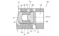
図1は、バルブ装置100の断面図である。バルブ装置100は、例えば、無段変速機の油圧を制御するためのバルブとして用いられる。 FIG. 1 is a sectional view of the
バルブ装置100は、作動流体としての作動油が流通するポートが複数形成される本体部10と、本体部10に摺動自在に収容されポート間の流れを制御するスプール20と、スプール20を第2方向(図1における左方向)に付勢するスプリング30と、を備える。 The
本体部10は、第1〜第7ポート11a〜11gが形成されるバルブボディ11と、一端がバルブボディ11の側面に開口する開口部12aを有しスプール20を収容する収容孔12と、収容孔12の開口部12aを閉塞するプラグ40と、を備える。 The
バルブボディ11には、一端側(図1における左側)から他端側(図1における右側)に間隔をあけて順に、常時一定の油圧が供給される第1ポート11aと、タンク(図示せず)に連通する第2ポート11bと、フィードバック圧が供給される第3ポート11cと、ライン圧通路(図示せず)に連通する第4ポート11dと、プーリの圧力室(図示せず)に連通する第5ポート11eと、タンク(図示せず)に連通する第6ポート11fと、信号圧が入力される第7ポート11gと、が形成される。なお、第3ポート11cと第5ポート11eとは、図示しない管路を通じて常時連通している。 The
スプール20は、円柱状の軸部21と、軸部21より大径で、軸部21の軸方向に間隔をあけて設けられた複数の第1〜第4ランド部22,23,24,25と、を有する。軸部21、及び第1〜第4ランド部22,23,24,25は、それぞれ同軸上に配置される。 The
第1〜第4ランド部22,23,24,25は、スプール20の一端側(図1における左側)から他端側(図1における右側)に向かって順に設けられ、収容孔12の内周面に沿って摺動する。第1ランド部22はスプール20の一端を構成し、第4ランド部25はスプール20の他端を構成する。また、第1ランド部22の外方側の側面が、スプール20の一方の端面20aを構成し、第4ランド部25の外方側の側面が、スプール20の他方の端面20bを構成する。 The first to
第1ランド部22は、第1ポート11aと第2ポート11bとの連通を常時遮断する。第2ランド部23は、第2ポート11bと第3ポート11cとの連通を常時遮断する。なお、第1ポート11aから、第1ランド部22と収容孔12の内周面との間に入り込んだ作動油は、つまり、第1ポート11aから第1ランド部22を通じて漏れた作動油は、第2ポート11bを通じてタンクに戻される。同様に、第3ポート11cから、第2ランド部23と収容孔12の内周面との間に入り込んだ作動油は、つまり、第3ポート11cから第1ランド部22を通じて漏れた作動油は、第2ポート11bを通じてタンクに戻される。 The
第3ランド部24は、第3ポート11cと第4ポート11dとの連通を常時遮断するとともに、第4ポート11dの開口量を制御する。第3ランド部24は、ライン圧通路(図示せず)から第4ポート11dを通じて供給されるライン圧を制御して、第5ポート11e(プーリ)への出力圧を制御する。 The
第4ランド部25は、第6ポート11fの開口量を制御するとともに、第6ポート11fと第7ポート11gとの連通を常時遮断する。第4ランド部25は、プーリの圧力室(図示せず)から第5ポート11eを通じてタンクに排出される油圧を制御する。なお、第7ポート11gから、第4ランド部25と収容孔12の内周面との間に入り込んだ作動油、つまり、第7ポート11gから第4ランド部25を通じて漏れた作動油は、第6ポート11fを通じてタンクに戻される。 The
第1ランド部22と第2ランド部23は、第3ランド部24よりも小径に形成される。また、第3ランド部24と第4ランド部25は、同じ径に形成される。 The
スプール20の第4ランド部25には、スプール20の他方の端面20bに開口するように形成された凹部26が設けられる。凹部26は、スプリング30の一端を保持する。 The
第4ランド部25は、収容孔12の内周面を摺動する摺動部25aと、摺動部25aよりも小径で摺動部25aよりも端面20b側に設けられた縮径部25bと、を備える。縮径部25bには、スプール20の径方向に縮径部25bを貫通するように形成された連通路としての貫通孔27が設けられる。貫通孔27は、スプール20の周方向に等間隔に複数設けられる。 The
プラグ40は、収容孔12内に挿入され、開口部12aを閉塞する。プラグ40の外周面と収容孔12の内周面との間でシールが形成される。プラグ40は、バルブボディ11に取り付けられた抜け止め部材50によって、収容孔12から抜け出ることが防止される。プラグ40は、スプリング30の他端を保持する。なお、プラグ40は、収容孔12に圧入などによって固定するようにしてもよい。 The
バルブ装置100は、スプール20の一方の端面20aに臨んで設けられ、スプール20を第1方向(図1における右方向)に移動させるための油圧が導かれる第1流体圧室13と、スプール20の他方の端面20bに臨んで設けられ、スプール20を第1方向とは反対の第2方向(図1における左方向)に移動させるための油圧が導かれる第2流体圧室14と、をさらに備える。 The
具体的には、第1流体圧室13は、収容孔12における収容孔12の底面12bとスプール20の端面20aとの間に形成され、第2流体圧室14は、収容孔12におけるプラグ40とスプール20の端面20bとの間に形成される。 Specifically, the first
第1流体圧室13は、第1ポート11aと常時連通し、第2流体圧室14は、第7ポート11gと常時連通する。 The first
次に、バルブ装置100の動作について説明する。 Next, the operation of the
図1は、スプール20に作用する第2流体圧室14内の油圧(信号圧)による付勢力とスプリング30による付勢力との合計が、第1流体圧室13内の油圧による付勢力と第3ポート11cから導入されたフィードバック圧による付勢力との合計よりも大きい状態を示している。この状態では、スプール20は、収容孔12の底面12bに当接している。また、この状態では、第4ポート11dの開口量が最大になり、第5ポート11eからプーリの圧力室へ出力される油圧が最大となる。 In FIG. 1, the total of the urging force of the hydraulic pressure (signal pressure) in the second
図1に示す状態から信号圧が低下し、スプール20に作用する第2流体圧室14内の油圧(信号圧)による付勢力とスプリング30による付勢力との合計が、第1流体圧室13内の油圧による付勢力と第3ポート11cから導入されたフィードバック圧による付勢力との合計よりも小さくなると、スプール20は第1方向(図1における右方向)に向かって移動する。これにより、第4ポート11dの開口量が徐々に小さくなり、第5ポート11eからプーリの圧力室へ出力される油圧が低下する。そして、スプール20に作用する第2流体圧室14内の油圧(信号圧)による付勢力とスプリング30による付勢力との合計と、第1流体圧室13内の油圧による付勢力と第3ポート11cから導入されたフィードバック圧による付勢力との合計と、が釣り合う位置でスプール20は停止する。 The signal pressure decreases from the state shown in FIG. 1, and the total of the urging force by the hydraulic pressure (signal pressure) in the second
信号圧がさらに低下すると、スプール20は第1方向(図1における右方向)に向かってさらに移動する。そして、スプール20の端面20bがプラグ40に当接すると、スプール20は停止する(図2参照)。この状態では、第4ポート11dは第3ランド部24によって遮断され、第5ポート11eと第6ポート11fとが連通する。これにより、プーリの圧力室内の油圧がタンク圧と等しくなる。 When the signal pressure further decreases, the
図2に示す状態から、再び信号圧を上昇させる、具体的には、第7ポート11gを通じて第2流体圧室14に油圧が供給されると、貫通孔27を通じて凹部26内に油圧が供給される。 The signal pressure is increased again from the state shown in FIG. 2. Specifically, when the hydraulic pressure is supplied to the second
貫通孔27が設けられていない場合、スプール20の端面20bがプラグ40に当接している状態では、凹部26内に油圧が供給されにくい。このため、第2流体圧室14に供給された油圧は、第4ランド部25の摺動部25aと縮径部25bとの段差部25cにのみ作用する。したがって、同じ圧力では、本実施形態のように凹部26の底面26aにも油圧が作用する場合に比べて、付勢力が小さくなる。このため、段差部25cに作用する第2流体圧室14の圧力が上昇し、段差部25cに作用する第2流体圧室14内の油圧(信号圧)による付勢力とスプリング30による付勢力との合計が、第1流体圧室13内の油圧による付勢力と第3ポート11cから導入されたフィードバック圧による付勢力との合計よりも大きくなるまでスプール20は停止しているので、応答が遅れてしまう。 When the through
これに対し、本実施形態では、スプール20が貫通孔27を備えているので、スプール20の端面20bがプラグ40に当接しているときに、第2流体圧室14に供給された油圧は貫通孔27を通じて凹部26の底面26aに作用することができる。これにより、応答が遅れることを抑制できる。 On the other hand, in the present embodiment, since the
さらに、貫通孔27を複数設けているので、凹部26内に素早く油圧が供給されるので、応答が遅れることをより抑制できる。 Further, since the plurality of through
なお、上記実施形態では、連通路として貫通孔27を例に説明したが、これに限らず、例えば、図4に示すように、連通路として、凹部26の開口端に凹部26の内部と外部を連通する溝状の切欠きを設けてもよい。さらに、図5に示すように、連通路をプラグ40に設けてもよい。 In addition, although the through
以上のように構成された本発明の実施形態の構成、作用、及び効果をまとめて説明する。 The configuration, operation, and effect of the embodiment of the present invention configured as described above will be collectively described.
バルブ装置100は、作動油が流通する第1〜第7ポート11a〜11gが形成される本体部10(バルブボディ11、プラグ40)と、本体部10(バルブボディ11)に摺動自在に収容され、ポート間の流れを制御するスプール20と、スプール20の一方の端面20aに臨んで設けられ、スプール20を第1方向に移動させるための油圧が導かれる第1流体圧室13と、スプール20の他方の端面20bに臨んで設けられ、スプール20を第1方向とは反対の第2方向に移動させるための油圧が導かれる第2流体圧室14と、第2流体圧室14に圧縮された状態で設けられスプール20を付勢するスプリング30と、スプール20の端面20bに開口するように形成され、スプリング30の一端を保持する凹部26と、スプール20の端面20bが本体部10(プラグ40)と当接したときに、凹部26の内部と第2流体圧室14とを連通する連通路(貫通孔27、切欠き127、切欠き227)と、を備える。 The
この構成によれば、スプール20の端面20bが本体部10(プラグ40)に当接しているときに、第2流体圧室14に供給された油圧は連通路(貫通孔27、切欠き127、切欠き227)を通じて凹部26の内部(底面26a)に作用することができる。これにより、応答が遅れることを抑制できる(請求項1に対応する効果)。 According to this configuration, when the
バルブ装置100では、本体部10は、第1〜第7ポート11a〜11gが形成されるバルブボディ11と、一端がバルブボディ11の側面に開口する開口部12aを有し、スプール20を収容する収容孔12と、収容孔12の開口部12aを閉塞するプラグ40と、を備える。 In the
また、バルブ装置100では、連通路は、スプール20、プラグ40及びバルブボディ11のいずれかに形成された孔(貫通孔27)または切欠き127、227である。 Further, in the
これらの構成によれば、加工を簡単することができる(請求項2、3に対応する効果)。 With these configurations, processing can be simplified (effects corresponding to claims 2 and 3).
バルブ装置100では、連通路(貫通孔27、切欠き127、切欠き227)は複数設けられる。 In the
この構成によれば、凹部26内により早く油圧を供給することができるので、応答が遅れることをより抑制できる(請求項4に対応する効果)。 According to this configuration, since the hydraulic pressure can be supplied to the
バルブ装置100では、連通路(貫通孔27、切欠き127、切欠き227)は、スプール20の周方向に等間隔に設けられる。 In the
この構成によれば、凹部26内に油圧を供給する際に、スプール20の周方向に均等に油圧が作用するので、スプール20が傾くことを防止できる。これにより、スプール20をスムーズに動作させることができる(請求項5に対応する効果)。 According to this configuration, when the hydraulic pressure is supplied to the
以上、本発明の実施形態について説明したが、上記実施形態は本発明の適用例の一部を示したものに過ぎず、本発明の技術的範囲を上記実施形態の具体的構成に限定する趣旨ではない。 Although the embodiments of the present invention have been described above, the above embodiments merely show a part of application examples of the present invention, and the technical scope of the present invention is limited to the specific configuration of the above embodiments. is not.
本実施形態では、バルブ装置100を無段変速機に適用する場合を例に説明したが、バルブ装置100は、どのような装置に適用されるものであってもよい。また、ランド部やポートの数も、どのようなものであってもよい。 In the present embodiment, the case where the
収容孔12は、バルブボディ11を貫通する孔であってもよい。この場合、両端の開口をプラグによって閉塞すればよい。 The
また、上記実施形態では、凹部26とスプリング30とが収容孔12の開口部12a側に設けられているが、凹部26とスプリング30とを収容孔12の底面12b側に設けるようにしてもよい。この場合、収容孔12の底面12bに溝などを設けて、この溝を連通路としてもよい。 Further, in the above embodiment, the
また、上記実施形態では、貫通孔27を複数設けていたが、貫通孔27は1つでもよい。 Further, although the plurality of through
100 バルブ装置
10 本体部
11 バルブボディ
11a 第1ポート
11b 第2ポート
11c 第3ポート
11d 第4ポート
11e 第5ポート
11f 第6ポート
11g 第7ポート
12 収容孔
12a 開口部
12b 底面
13 第1流体圧室
14 第2流体圧室
20 スプール
20a 端面
20b 端面
26 凹部
27 貫通孔(連通路)
30 スプリング
40 プラグ
127 切欠き(連通路)
227 切欠き(連通路)100
30
227 Notch (communication passage)
Claims (5)
Translated fromJapanese前記本体部に摺動自在に収容され、前記ポート間の流れを制御するスプールと、
前記スプールの一方の端面に臨んで設けられ、前記スプールを第1方向に移動させるための油圧が導かれる第1流体圧室と、
前記スプールの他方の端面に臨んで設けられ、前記スプールを前記第1方向とは反対の第2方向に移動させるための油圧が導かれる第2流体圧室と、
前記第2流体圧室に圧縮された状態で設けられ、前記スプールを付勢するスプリングと、
前記スプールの前記他方の端面に開口するように形成され、前記スプリングの一端を保持する凹部と、
前記スプールの前記他方の端面が前記本体部と当接したときに、前記凹部の内部と前記第2流体圧室とを連通する連通路と、を備えることを特徴とするバルブ装置。A main body portion having a plurality of ports through which the working fluid flows,
A spool that is slidably accommodated in the main body and controls the flow between the ports,
A first fluid pressure chamber which is provided so as to face one end surface of the spool, and through which a hydraulic pressure for moving the spool in the first direction is guided;
A second fluid pressure chamber which is provided so as to face the other end surface of the spool, and through which a hydraulic pressure for moving the spool in a second direction opposite to the first direction is guided;
A spring that is provided in a compressed state in the second fluid pressure chamber and urges the spool;
A recess formed to open to the other end surface of the spool and holding one end of the spring;
A valve device comprising: a communication passage that communicates the inside of the recess with the second fluid pressure chamber when the other end surface of the spool comes into contact with the main body portion.
前記本体部は、
前記ポートが形成されるバルブボディと、
一端が前記バルブボディの側面に開口する開口部を有し、前記スプールを収容する収容孔と、
前記収容孔の前記開口部を閉塞するプラグと、を備えることを特徴とするバルブ装置。The valve device according to claim 1,
The main body is
A valve body in which the port is formed,
An accommodating hole having one end having an opening opening to a side surface of the valve body and accommodating the spool,
A plug that closes the opening of the housing hole.
前記連通路は、前記スプール、前記プラグ及び前記バルブボディのいずれかに形成された孔または切欠きであることを特徴とするバルブ装置。The valve device according to claim 2,
The valve device, wherein the communication passage is a hole or a notch formed in any of the spool, the plug, and the valve body.
前記連通路は複数設けられることを特徴とするバルブ装置。The valve device according to any one of claims 1 to 3,
A valve device comprising a plurality of the communication passages.
複数の前記連通路は、前記スプールの周方向に等間隔に設けられることを特徴とするバルブ装置。The valve device according to claim 4,
The valve device, wherein the plurality of communication passages are provided at equal intervals in the circumferential direction of the spool.
Priority Applications (1)
| Application Number | Priority Date | Filing Date | Title |
|---|---|---|---|
| JP2018238600AJP2020101215A (en) | 2018-12-20 | 2018-12-20 | Valve device |
Applications Claiming Priority (1)
| Application Number | Priority Date | Filing Date | Title |
|---|---|---|---|
| JP2018238600AJP2020101215A (en) | 2018-12-20 | 2018-12-20 | Valve device |
Publications (1)
| Publication Number | Publication Date |
|---|---|
| JP2020101215Atrue JP2020101215A (en) | 2020-07-02 |
Family
ID=71139271
Family Applications (1)
| Application Number | Title | Priority Date | Filing Date |
|---|---|---|---|
| JP2018238600APendingJP2020101215A (en) | 2018-12-20 | 2018-12-20 | Valve device |
Country Status (1)
| Country | Link |
|---|---|
| JP (1) | JP2020101215A (en) |
Cited By (1)
| Publication number | Priority date | Publication date | Assignee | Title |
|---|---|---|---|---|
| DE112022002292T5 (en) | 2020-06-10 | 2024-03-14 | Denso Corporation | Presentation control device, presentation control program, autonomous driving control device and autonomous driving control program |
Citations (3)
| Publication number | Priority date | Publication date | Assignee | Title |
|---|---|---|---|---|
| JPS57163705A (en)* | 1981-02-12 | 1982-10-08 | Herion Werke Kg | Pressure safety valve |
| JPH0233980U (en)* | 1988-08-29 | 1990-03-05 | ||
| US20170234176A1 (en)* | 2016-02-11 | 2017-08-17 | SLPT Global Pump Group | Automotive lubricant pumping system with two piece relief valve |
- 2018
- 2018-12-20JPJP2018238600Apatent/JP2020101215A/enactivePending
Patent Citations (3)
| Publication number | Priority date | Publication date | Assignee | Title |
|---|---|---|---|---|
| JPS57163705A (en)* | 1981-02-12 | 1982-10-08 | Herion Werke Kg | Pressure safety valve |
| JPH0233980U (en)* | 1988-08-29 | 1990-03-05 | ||
| US20170234176A1 (en)* | 2016-02-11 | 2017-08-17 | SLPT Global Pump Group | Automotive lubricant pumping system with two piece relief valve |
Cited By (1)
| Publication number | Priority date | Publication date | Assignee | Title |
|---|---|---|---|---|
| DE112022002292T5 (en) | 2020-06-10 | 2024-03-14 | Denso Corporation | Presentation control device, presentation control program, autonomous driving control device and autonomous driving control program |
Similar Documents
| Publication | Publication Date | Title |
|---|---|---|
| JP4942833B2 (en) | Relief valve with relief pressure change function | |
| KR960016822B1 (en) | Inertial body driving unit | |
| JP5848721B2 (en) | Buffer valve | |
| US10895269B2 (en) | Double acting hydraulic pressure intensifier | |
| JP2020101215A (en) | Valve device | |
| US11879452B2 (en) | Pump displacement control device having a feedback lever | |
| JP6857571B2 (en) | Fluid pressure controller | |
| JP6375212B2 (en) | Variable displacement vane pump | |
| WO2019216193A1 (en) | Electromagnetic flow control valve | |
| CN110030219B (en) | Pilot operated directional control valve and valve system including the same | |
| WO2019138612A1 (en) | Control valve | |
| US11262768B2 (en) | Cap with electromagnetic proportional valve | |
| JP5601510B2 (en) | Relief valve | |
| WO2023032576A1 (en) | Pressure compensation valve | |
| JP7055549B2 (en) | valve | |
| JP4988775B2 (en) | Hydraulic valve assembly | |
| JP6154874B2 (en) | valve | |
| JP2002188604A (en) | Hydraulic control valve | |
| WO2016047597A1 (en) | Spool valve | |
| WO2015075839A1 (en) | Flow rate control valve | |
| JP2019157949A (en) | Control valve | |
| KR102859079B1 (en) | Flow control valve and working machine | |
| US20190376534A1 (en) | Electromagnetic pressure reducing valve and fluid pressure control device including electromagnetic pressure reducing valve | |
| WO2019172131A1 (en) | Control valve | |
| KR102149963B1 (en) | Spool with improved workability and precise controllability and a flow control valve using the spool |
Legal Events
| Date | Code | Title | Description |
|---|---|---|---|
| A621 | Written request for application examination | Free format text:JAPANESE INTERMEDIATE CODE: A621 Effective date:20210609 | |
| A131 | Notification of reasons for refusal | Free format text:JAPANESE INTERMEDIATE CODE: A131 Effective date:20220531 | |
| A977 | Report on retrieval | Free format text:JAPANESE INTERMEDIATE CODE: A971007 Effective date:20220531 | |
| A02 | Decision of refusal | Free format text:JAPANESE INTERMEDIATE CODE: A02 Effective date:20221122 |