JP2020099345A - Heating control arrangements for electronic smoking articles, and related systems and methods - Google Patents
Heating control arrangements for electronic smoking articles, and related systems and methodsDownload PDFInfo
- Publication number
- JP2020099345A JP2020099345AJP2020035502AJP2020035502AJP2020099345AJP 2020099345 AJP2020099345 AJP 2020099345AJP 2020035502 AJP2020035502 AJP 2020035502AJP 2020035502 AJP2020035502 AJP 2020035502AJP 2020099345 AJP2020099345 AJP 2020099345A
- Authority
- JP
- Japan
- Prior art keywords
- voltage
- resistor
- heating device
- power
- actual
- Prior art date
- Legal status (The legal status is an assumption and is not a legal conclusion. Google has not performed a legal analysis and makes no representation as to the accuracy of the status listed.)
- Granted
Links
Images


Classifications
- A—HUMAN NECESSITIES
- A24—TOBACCO; CIGARS; CIGARETTES; SIMULATED SMOKING DEVICES; SMOKERS' REQUISITES
- A24F—SMOKERS' REQUISITES; MATCH BOXES; SIMULATED SMOKING DEVICES
- A24F40/00—Electrically operated smoking devices; Component parts thereof; Manufacture thereof; Maintenance or testing thereof; Charging means specially adapted therefor
- A24F40/50—Control or monitoring
- A—HUMAN NECESSITIES
- A24—TOBACCO; CIGARS; CIGARETTES; SIMULATED SMOKING DEVICES; SMOKERS' REQUISITES
- A24F—SMOKERS' REQUISITES; MATCH BOXES; SIMULATED SMOKING DEVICES
- A24F40/00—Electrically operated smoking devices; Component parts thereof; Manufacture thereof; Maintenance or testing thereof; Charging means specially adapted therefor
- A24F40/40—Constructional details, e.g. connection of cartridges and battery parts
- A24F40/46—Shape or structure of electric heating means
- A—HUMAN NECESSITIES
- A24—TOBACCO; CIGARS; CIGARETTES; SIMULATED SMOKING DEVICES; SMOKERS' REQUISITES
- A24F—SMOKERS' REQUISITES; MATCH BOXES; SIMULATED SMOKING DEVICES
- A24F40/00—Electrically operated smoking devices; Component parts thereof; Manufacture thereof; Maintenance or testing thereof; Charging means specially adapted therefor
- A24F40/50—Control or monitoring
- A24F40/51—Arrangement of sensors
- A—HUMAN NECESSITIES
- A24—TOBACCO; CIGARS; CIGARETTES; SIMULATED SMOKING DEVICES; SMOKERS' REQUISITES
- A24F—SMOKERS' REQUISITES; MATCH BOXES; SIMULATED SMOKING DEVICES
- A24F40/00—Electrically operated smoking devices; Component parts thereof; Manufacture thereof; Maintenance or testing thereof; Charging means specially adapted therefor
- A24F40/50—Control or monitoring
- A24F40/53—Monitoring, e.g. fault detection
- A—HUMAN NECESSITIES
- A24—TOBACCO; CIGARS; CIGARETTES; SIMULATED SMOKING DEVICES; SMOKERS' REQUISITES
- A24F—SMOKERS' REQUISITES; MATCH BOXES; SIMULATED SMOKING DEVICES
- A24F40/00—Electrically operated smoking devices; Component parts thereof; Manufacture thereof; Maintenance or testing thereof; Charging means specially adapted therefor
- A24F40/60—Devices with integrated user interfaces
- A—HUMAN NECESSITIES
- A24—TOBACCO; CIGARS; CIGARETTES; SIMULATED SMOKING DEVICES; SMOKERS' REQUISITES
- A24F—SMOKERS' REQUISITES; MATCH BOXES; SIMULATED SMOKING DEVICES
- A24F40/00—Electrically operated smoking devices; Component parts thereof; Manufacture thereof; Maintenance or testing thereof; Charging means specially adapted therefor
- A24F40/65—Devices with integrated communication means, e.g. wireless communication means
- A—HUMAN NECESSITIES
- A61—MEDICAL OR VETERINARY SCIENCE; HYGIENE
- A61M—DEVICES FOR INTRODUCING MEDIA INTO, OR ONTO, THE BODY; DEVICES FOR TRANSDUCING BODY MEDIA OR FOR TAKING MEDIA FROM THE BODY; DEVICES FOR PRODUCING OR ENDING SLEEP OR STUPOR
- A61M15/00—Inhalators
- A61M15/06—Inhaling appliances shaped like cigars, cigarettes or pipes
- F—MECHANICAL ENGINEERING; LIGHTING; HEATING; WEAPONS; BLASTING
- F24—HEATING; RANGES; VENTILATING
- F24H—FLUID HEATERS, e.g. WATER OR AIR HEATERS, HAVING HEAT-GENERATING MEANS, e.g. HEAT PUMPS, IN GENERAL
- F24H9/00—Details
- F24H9/0005—Details for water heaters
- H—ELECTRICITY
- H02—GENERATION; CONVERSION OR DISTRIBUTION OF ELECTRIC POWER
- H02J—CIRCUIT ARRANGEMENTS OR SYSTEMS FOR SUPPLYING OR DISTRIBUTING ELECTRIC POWER; SYSTEMS FOR STORING ELECTRIC ENERGY
- H02J7/00—Circuit arrangements for charging or depolarising batteries or for supplying loads from batteries
- H02J7/007—Regulation of charging or discharging current or voltage
- H—ELECTRICITY
- H05—ELECTRIC TECHNIQUES NOT OTHERWISE PROVIDED FOR
- H05B—ELECTRIC HEATING; ELECTRIC LIGHT SOURCES NOT OTHERWISE PROVIDED FOR; CIRCUIT ARRANGEMENTS FOR ELECTRIC LIGHT SOURCES, IN GENERAL
- H05B1/00—Details of electric heating devices
- H05B1/02—Automatic switching arrangements specially adapted to apparatus ; Control of heating devices
- H05B1/0202—Switches
- A—HUMAN NECESSITIES
- A24—TOBACCO; CIGARS; CIGARETTES; SIMULATED SMOKING DEVICES; SMOKERS' REQUISITES
- A24F—SMOKERS' REQUISITES; MATCH BOXES; SIMULATED SMOKING DEVICES
- A24F40/00—Electrically operated smoking devices; Component parts thereof; Manufacture thereof; Maintenance or testing thereof; Charging means specially adapted therefor
- A24F40/10—Devices using liquid inhalable precursors
- A—HUMAN NECESSITIES
- A24—TOBACCO; CIGARS; CIGARETTES; SIMULATED SMOKING DEVICES; SMOKERS' REQUISITES
- A24F—SMOKERS' REQUISITES; MATCH BOXES; SIMULATED SMOKING DEVICES
- A24F47/00—Smokers' requisites not otherwise provided for
Landscapes
- Engineering & Computer Science (AREA)
- Health & Medical Sciences (AREA)
- General Engineering & Computer Science (AREA)
- Physics & Mathematics (AREA)
- Thermal Sciences (AREA)
- Chemical & Material Sciences (AREA)
- Combustion & Propulsion (AREA)
- Mechanical Engineering (AREA)
- Bioinformatics & Cheminformatics (AREA)
- Hematology (AREA)
- Veterinary Medicine (AREA)
- Pulmonology (AREA)
- Anesthesiology (AREA)
- Biomedical Technology (AREA)
- Heart & Thoracic Surgery (AREA)
- Public Health (AREA)
- Life Sciences & Earth Sciences (AREA)
- Animal Behavior & Ethology (AREA)
- General Health & Medical Sciences (AREA)
- Power Engineering (AREA)
- Computer Networks & Wireless Communication (AREA)
- Human Computer Interaction (AREA)
- Control Of Resistance Heating (AREA)
Abstract
Translated fromJapaneseDescription
Translated fromJapanese本開示は、エアロゾル送給物品およびその使用に関し、詳細には、タバコおよび他の物質の成分を吸入可能な形で提供する目的のために喫煙物品であると考えることができる物品に関する。そのような物品の非常に好適な成分がタバコから製造または導出されるか、または、それらの物品は、人の消費のためにタバコをその他の方法で組み込むと特徴づけることができる。 The present disclosure relates to aerosol-delivered articles and their uses, and in particular to articles that may be considered smoking articles for the purpose of providing inhalable components of tobacco and other substances. Very suitable ingredients for such articles are manufactured or derived from tobacco, or they can be characterized as otherwise incorporating tobacco for human consumption.
多くの喫煙装置が、長年の間、使用のためにタバコを燃焼させることを必要とする喫煙製品の改良物または代替物としての提案されている。それらの装置の多くは、意図的に、タバコ、葉巻、または、パイプ喫煙に関連した感覚を提供するが、タバコの燃焼から生じるかなりの量の不完全燃焼および熱分解生成物質を送給することがないように設計されている。この目的のために、揮発性物質を気化させるかまたは加熱するか、または、タバコをかなりの程度まで燃焼させることなくタバコ、葉巻、またはパイプ喫煙の感覚を提供しようとするために電気エネルギーを利用する多数の喫煙製品、香り発生器および医薬吸入器が提案されている。例えば、参考として本明細書に組み入れられる、Robinsonらの米国特許第7,726,320号と、2012年10月8日出願のSearsらの米国特許出願第13/647,000号とで説明されている背景技術で述べる様々な代替喫煙物品、エアロゾル送給装置および熱発生源を参照されたい。 Many smoking devices have been proposed for many years as an improvement or alternative to smoking products that require burning the tobacco for use. Many of these devices intentionally provide the sensation associated with smoking cigarettes, cigars, or pipes, but deliver significant amounts of incomplete combustion and pyrolysis products resulting from the burning of tobacco. Is designed to be free. To this end, the use of electrical energy to vaporize or heat volatile substances or to try to provide the sensation of smoking a cigarette, cigar, or pipe without burning the cigarette to a considerable extent. Numerous smoking products, scent generators and medicinal inhalers have been proposed. For example, described in US Patent No. 7,726,320 to Robinson et al. and US Patent Application No. 13/6477,000 to Sears et al., filed October 8, 2012, which is incorporated herein by reference. See various alternative smoking articles, aerosol delivery devices and heat sources described in the Background of the Invention.
煙またはエアロゾル形成用に熱を発生させるために電気エネルギーを採用した特定のタバコ製品、および、特に、電子たばこ製品と呼ばれる特定の製品が、世界中で市販されてきた。従来の形式のタバコ、葉巻、または、パイプの属性の多くに似た代表的な製品は、Philip Morris Incorporated製ACCORD(登録商標)、InnoVapor LLC製ALPHA(商標)、JOYE 510(商標)およびM4(商標)、White Cloud Cigarettes製CIRRUS(商標)およびFLING(商標)、Epuffer(登録商標)International,Inc.製COHITA(商標)、COLIBRI(商標)、ELITE CLASSIC(登録商標)、MAGNUM(商標)、PHANTOM(商標)およびSENSE)(商標)、Electronic Cigarettes,Inc.製DUOPRO(商標)(STORM(商標)およびVAPORKINGr)(登録商標)、Egar Australia製EGAR(商標)、Joyetech製eGO−C(商標)およびeGO−T(商標)、Elusion UK Ltd製ELUSION(商標)、Eonsmoke LLC製EONSMOKE(登録商標)、Green Smoke Inc.USA製Green Smoke (登録商標)、Greenarette LLC製GREENARETTE(商標)、Smoke Stik(登録商標)製HALLIGAN(商標)、HENDU(商標)、Jet(商標)、MAXXQ(商標)、PINK(商標)およびPITBULL)(商標)、Philip Morris International,Inc.製HEATBAR(商標)、Crown7製HYDRO IMPERIAL(商標)およびLXE(商標)、LOGIC Technology製LOGIC(商標)およびTHE CUBAN (商標)、Luciano Smokes Inc.製LUCI(登録商標)、Nicotek LLC製METRO(登録商標)、Sottera,Inc.製NJOY(登録商標)およびONEJOY(商標)、SS Choice LLC製NO.7 (登録商標)、PremiumEstore LLC製PREMIUM ELECTRONIC CIGARETTE (商標)、Ruyan America,Inc製Rapp E−MYSTICK (商標)、Red Dragon Products,LLC製Red DRAGON (登録商標)、Ruyan Group(Holdings)Ltd.製RUYAN (登録商標)、The Smart Smoking Electronic Cigarette Company Ltd.製SMART SMOKER (登録商標)、Coastline Products LLC製SMOKE ASSIST (登録商標)、Smoking Everywhere,Inc.製SMOKING EVERYWHERE (登録商標)VMR Products LLC製V2CIGS(商標)、VaporNine LLC製VAPOR NINE (商標)、Vapor 4 Life,Inc.製VAPOR4LIFE (登録商標)、E−CigaretteDirect,LLC製VEPPO(商標)、 および、R.J.Reynolds Vapor Company製VUSE(登録商標)として販売されてきた。更に他の電動エアロゾル送給装置、および、特にいわゆる電子たばこと特徴づけられた装置が、商品名COOLER VISIONS(商標)、DIRECT E−CIG(登録商標)、DRAGONFLY(商標)、EMIST(商標)、EVERSMOKE(商標)、GAMUCCI(登録商標)、HYBRID FLAME(商標)、KNIGHT STICKS(商標)、ROYAL BLUES(商標)、SMOKETIP(登録商標)、およびSOUTH BEACH SMOKE(商標)で販売されてきた。 Certain tobacco products that employ electrical energy to generate heat for smoke or aerosol formation, and in particular, certain products referred to as electronic tobacco products, have been marketed worldwide. Typical products that resemble many of the attributes of conventional types of tobacco, cigars, or pipes are Philips Morris Incorporated's ACCORD(R), InnoVapor LLC's ALPHA(TM), JOYE 510(TM) and M4 ( Trademark), CIRRUS(TM) and FLING(TM) from White Cloud Cigarettes, Epuffer(R) International, Inc. Manufactured by COHITA™, COLIBRI™, ELITE CLASSIC™, MAGNUM™, PHANTOM™ and SENSE™, Electronic Cigarettes, Inc. DUOPRO(TM) (STORM(TM) and VAPORKINGr)(R), Egar Australia's EGAR(TM), Joytech's eGO-C(TM) and eGO-T(TM), Elusion UK Ltd's ELUSION(TM). , Eonsmoke (registered trademark) manufactured by Eonsmoke LLC, Green Smoke Inc. USA Green Smoke(R), Greenarette LLC Green ARETTE(TM), Smoke Stik(R) HALLIGAN(TM), HENDU(TM), Jet(TM), MAXXQ(TM), PINK(TM) and PITBUL. )(TM), Philip Morris International, Inc. HEATBAR™, Crown 7 HYDRO IMPERIAL™ and LXE™, LOGIC Technology LOGIC™ and THE CUBAN™, Luciano Smokes Inc. LUCI (registered trademark), Nicotek LLC METRO (registered trademark), Sottera, Inc. NJOY (registered trademark) and ONEJOY (trademark) manufactured by SS Choice LLC NO. 7 (registered trademark), PREMIUM ESTOR LLC LLC PREMIUM ELECTRONIC CIGARETTE (trademark), Ruyan America, Inc Rapp E-MYSTICK (trademark), Red Dragondru. Manufactured by RUYAN (registered trademark), The Smart Smoketing Electronic Cigarette Company Ltd. SMART SMOKER (registered trademark) manufactured by Coastline Products LLC, SMOKE ASIST (registered trademark) manufactured by Coastline Products LLC, Smoking Everywhere, Inc. V2CIGS (trademark) manufactured by SMOKING EVERYWHERE (registered trademark) VMR Products LLC, VAPOR NINE (trademark) manufactured by VaporNine LLC, Vapor 4 Life, Inc. VAPOR4LIFE (registered trademark) manufactured by E-CigaretteDirect, VEPPO (trademark) manufactured by LLC, and R.I. J. It has been sold as VUSE® from Reynolds Vapor Company. Still other electric aerosol delivery devices, and in particular so-called electronic cigarettes and characterized devices, are trade names COOLER VISIONS™, DIRECT E-CIG™, DRAGONFLY™, EMIST™, It has been sold under the EVERSMOKE™, GAMUCCI™, HYBRID FLAME™, KNIGHT STICKS™, ROYAL BLUES™, SMOKETIP™, and SOUTH BEACH SMOKE™.
タバコ、葉巻、または、パイプ喫煙の感覚を提供するために電気エネルギーによって生成された熱を利用して、タバコをかなりの程度まで燃焼させることなく熱を採用し、燃焼熱源を必要とせずに熱を採用し、かつ、かなりの量の不完全燃焼および熱分解製品を必然的に送給することなく熱を採用する喫煙物品を提供することが望ましいであろう。 Utilizes the heat generated by electrical energy to provide the sensation of smoking a cigarette, cigar, or pipe, and adopts heat without burning the cigarette to any significant extent, and without the need for a combustion heat source. It would be desirable to provide a smoking article which employs heat and which employs heat without necessarily delivering a significant amount of incomplete combustion and pyrolysis products.
上記および他の必要性は、本開示の態様によって対処され、一態様では、電子喫煙物品のエアロゾル前駆体構成の加熱を制御する方法を提供する。そのような方法は、電源からエアロゾル前駆体構成を加熱するように配置され、かつ、加熱期間を相応して開始する加熱装置まで平均電力を導くことを含み、平均電力は、電源に関連した選択された電力設定点に対応する。加熱装置に導かれた実出力は、加熱装置を通る加熱装置および電流にて電圧の積として決定され、実出力は、平均電力と比較される。加熱装置に導かれた平均電力は、実出力を選択された電力設定点の方に導くように調節される。実出力は、周期的に判定されて平均電力と比較され、平均電力は、加熱期間の満了まで、実出力を選択された電力設定点の方に導くように調節される。 The above and other needs are addressed by aspects of the present disclosure, which in one aspect provide a method of controlling heating of an aerosol precursor composition of an electronic smoking article. Such a method comprises directing the average power to a heating device arranged to heat the aerosol precursor composition from the power source and correspondingly initiating the heating period, the average power being a selection related to the power source. Corresponding to the set power set point. The actual power delivered to the heater is determined as the product of the voltage at the heater and the current through the heater and the actual power is compared to the average power. The average power delivered to the heating device is adjusted to drive the actual output towards the selected power set point. The actual power is periodically determined and compared to the average power, which is adjusted to direct the actual power towards the selected power set point until the end of the heating period.
本開示の別の態様では、処理回路を含む装置を提供する。この例示的な実施形態の処理回路は、方法の態様のステップを少なくとも実行するように装置を制御するように構成され得る。 Another aspect of the disclosure provides an apparatus including a processing circuit. The processing circuitry of this exemplary embodiment may be configured to control the device to at least perform the steps of the method aspects.
本開示の更に別の態様では、上に記憶されたコンピュータプログラムコードを有する少なくとも1つの非一時的なコンピュータ可読記憶媒体を含むコンピュータプログラム製品を提供する。この実施形態のプログラムコードは、実行されると少なくとも方法の態様のステップを実行するプログラムコードを含んでよい。 In yet another aspect of the present disclosure, there is provided a computer program product including at least one non-transitory computer readable storage medium having computer program code stored thereon. The program code of this embodiment may include program code that, when executed, performs at least the steps of method aspects.
本開示は、したがって以下の実施形態を制限なしに含む。 The present disclosure thus includes the following embodiments without limitation.
実施形態1:電子喫煙物品のエアロゾル前駆体構成の加熱を制御する方法であって、平均電力を電源からエアロゾル前駆体構成を加熱するように配置された加熱装置に導いて加熱期間を相応して開始するステップであって、平均電力は、電源に関連した選択された電力設定点に対応する、開始することと、加熱装置に導かれた実出力を加熱装置での電圧および加熱装置を通る電流の積として決定することと、実出力を平均電力と比較することと、実出力を選択された電力設定点の方に導くように加熱装置に導かれた平均電力を調節することと、周期的に実出力を判定し、平均電力に実出力を比較して、加熱期間の満了まで、実出力を選択された電力設定点の方に導くために平均電力を調節することと、を含む方法。 Embodiment 1: A method of controlling the heating of an aerosol precursor composition of an electronic smoking article, the average power being directed from a power source to a heating device arranged to heat the aerosol precursor composition, and the heating period correspondingly. The step of starting is that the average power corresponds to the selected power setpoint associated with the power supply, starting and the actual power delivered to the heating device is the voltage at the heating device and the current through the heating device. , Comparing the actual power with the average power, adjusting the average power delivered to the heating device to drive the actual power towards the selected power setpoint, and Determining the actual power and comparing the actual power to the average power and adjusting the average power to direct the actual power towards the selected power setpoint until the end of the heating period.
実施形態2:平均電力を電源から加熱装置に導くことにより加熱期間を開始することは、電流の流れを電源から加熱装置に導くために、電源と加熱装置と間で電気的に連絡してスイッチデバイスを起動させることを更に含む、前述または後述の実施形態のいずれかまたはその組み合わせの方法。 Embodiment 2: Initiating a heating period by directing average power from the power supply to the heating device is a switch in electrical communication between the power supply and the heating device to conduct current flow from the power supply to the heating device. The method of any of the above or below embodiments or combinations thereof further comprising activating the device.
実施形態3:加熱装置での実電圧を基準電圧と比較することによって加熱装置での電圧を判定することを更に含む、前述または後述の実施形態のいずれかまたはその組み合わせの方法。 Embodiment 3: The method of any of the above or below embodiments or a combination thereof further comprising determining the voltage at the heating device by comparing the actual voltage at the heating device with a reference voltage.
実施形態4:加熱装置での実電圧は、低値である約2.0Vと高値である約4.2Vの間であり、加熱装置での実電圧を基準電圧と比較することは、分圧器を実電圧に適用して、分圧電圧をプロセッサの内部基準電圧と比較することを更に含み、分圧電圧は、実電圧の低い値および高い値に対応する低い値および高い値を有する、前述または後述の実施形態のいずれかまたはその組み合わせの方法。 Embodiment 4: The actual voltage at the heating device is between a low value of about 2.0 V and a high value of about 4.2 V, comparing the actual voltage at the heating device with a reference voltage is a voltage divider. To the actual voltage and comparing the divided voltage to the internal reference voltage of the processor, the divided voltage having low and high values corresponding to low and high values of the actual voltage, respectively. Alternatively, a method of any of the embodiments described below or a combination thereof.
実施形態5:分圧電圧をプロセッサの内部基準電圧と比較することは、分圧電圧を分圧電圧の高い値よりも大きい内部基準電圧と比較することを更に含む、前述または後述の実施形態のいずれかまたはその組み合わせの方法。 Embodiment 5: Comparing the divided voltage with an internal reference voltage of the processor further comprises comparing the divided voltage with an internal reference voltage greater than a high value of the divided voltage. Either or a combination of methods.
実施形態6:分圧器を適用することは、第2の抵抗器と、第1の抵抗器および第2の抵抗器の合計との比により電圧加熱装置で実電圧を乗算することを更に含む、前述または後述の実施形態のいずれかまたはその組み合わせの方法。 Embodiment 6: Applying a voltage divider further comprises multiplying the actual voltage at the voltage heating device by the ratio of the second resistor and the sum of the first resistor and the second resistor, A method of any or combination of the embodiments described above or below.
実施形態7:分圧器を適用することは、
約500kOhm〜約1000kOhmの第1の抵抗器を含む分圧器および約100kOhm〜約500kOhmの第2の抵抗器を適用することと、
第1の抵抗器および第2の抵抗器を含みかつ第1の抵抗器と第2の抵抗器間の抵抗比が約1:1〜約10:1である分圧器を適用することと、
第1の抵抗器および第2の抵抗器を含みかつ第1の抵抗器と第2の抵抗器間の抵抗比が約5:1である分圧器を適用することと、
第1の抵抗器および第2の抵抗器を含みかつプロセッサの内部基準電圧と分圧電圧の高値との間の比に対応する第1の抵抗器と第2の抵抗器間の抵抗比を有するのうちの1つを更に含む、前述または後述の実施形態のいずれかまたはその組み合わせの方法。Embodiment 7: Applying a voltage divider
Applying a voltage divider including a first resistor of about 500 kOhm to about 1000 kOhm and a second resistor of about 100 kOhm to about 500 kOhm;
Applying a voltage divider comprising a first resistor and a second resistor and having a resistance ratio between the first resistor and the second resistor of about 1:1 to about 10:1;
Applying a voltage divider comprising a first resistor and a second resistor and having a resistance ratio between the first resistor and the second resistor of about 5:1;
A first resistor and a second resistor are included and have a resistance ratio between the first resistor and the second resistor that corresponds to a ratio between an internal reference voltage of the processor and a high value of the divided voltage. The method of any of the above or below embodiments or a combination thereof, further comprising one of:
実施形態8:分圧器を適用することは、入力電圧の表現をプロセッサの電圧アナログ/デジタル変換器に対して形成するように分圧器を実電圧に適用することを更に含む前述または後述の実施形態のいずれかまたはその組み合わせの方法。 Embodiment 8: Applying a voltage divider further comprises applying a voltage divider to the actual voltage to form a representation of the input voltage to the voltage analog-to-digital converter of the processor. Either or a combination of methods.
実施形態9:加熱装置と電源との間に直列に配置された抵抗器全体にわたる電圧降下を決定することによって加熱装置を通る電流を判定することを更に含む、前述または後述の実施形態のいずれかまたはその組み合わせの方法。 Embodiment 9: Any of the preceding or following embodiments further comprising determining the current through the heating device by determining the voltage drop across a resistor placed in series between the heating device and the power supply. Or the combination method.
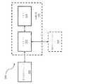
実施形態10:電子喫煙物品のエアロゾル前駆体構成のための加熱制御装置であって、エアロゾル前駆体構成を加熱するように配置された加熱装置と、加熱装置と通信する電源と、加熱装置および電源と通信する制御装置と、を含み、制御装置は、電源に、平均電力を加熱装置に提供して加熱期間を相応して開始するように指示し、平均電力は、電源に関連した選択された電力設定点に対応し、更に、加熱装置に導かれた実出力を加熱装置での電圧および加熱装置を通る電流の積として決定し、実出力を平均電力と比較し、実出力を選択された電力設定点の方に導くように加熱装置に導かれた平均電力を調節し、および、実出力を周期的に判定し、平均電力に実出力を比較して、加熱期間の満了まで、実出力を選択された電力設定点の方に導くために平均電力を調節するように少なくとも指示するように構成されたプロセッサを有する、制御装置。 Embodiment 10: A heating control device for an aerosol precursor composition of an electronic smoking article, the heating device being arranged to heat the aerosol precursor composition, a power supply in communication with the heating device, a heating device and a power supply. A controller in communication with the controller, the controller instructing the power supply to provide the average power to the heating device to start the heating period accordingly, the average power being selected relative to the power supply. Corresponding to the power set point, the actual output directed to the heating device was determined as the product of the voltage at the heating device and the current through the heating device, the actual output was compared to the average power, and the actual output was selected. Adjust the average power delivered to the heating device to direct it towards the power set point, and periodically determine the actual output, compare the actual output to the average power, and output the actual output until the end of the heating period. A controller having a processor configured to at least instruct to adjust the average power to direct the power to a selected power set point.
実施形態11:制御装置は、更に、電流の流れを電源から加熱装置に導くために、電源と加熱装置と間で電気的に連絡してスイッチデバイスを起動させるように構成される、前述または後述の実施形態のいずれかまたはその組み合わせの加熱制御装置。 Embodiment 11: The control device is further configured to electrically contact between the power supply and the heating device to activate the switching device to direct the flow of current from the power supply to the heating device. Of any of the embodiments or combinations thereof.
実施形態12:制御装置は、更に、加熱装置での実電圧を基準電圧と比較することによって加熱装置での電圧を判定するように構成される前述または後述の実施形態のいずれかまたはその組み合わせの加熱制御装置。 Embodiment 12: The controller further comprises any or a combination of any of the above or below embodiments configured to determine the voltage at the heating device by comparing the actual voltage at the heating device with a reference voltage. Heating control device.
実施形態13:加熱装置での実電圧は、低値である約2.0Vと高値である約4.2Vの間であり、制御装置は、更に、分圧器を実電圧に適用して、分圧電圧をプロセッサの内部基準電圧と比較するように構成され、分圧電圧は、実電圧の低い値および高い値に対応する低い値および高い値を有する、前述または後述の実施形態のいずれかまたはその組み合わせの加熱制御装置。 Embodiment 13: The actual voltage at the heating device is between a low value of about 2.0 V and a high value of about 4.2 V, and the controller further applies a voltage divider to the actual voltage to divide the voltage. Any of the embodiments described above or below, wherein the divided voltage is configured to compare to the internal reference voltage of the processor, and the divided voltage has low and high values corresponding to low and high values of the actual voltage, respectively. The heating control device of the combination.
実施形態14:制御装置は、更に、分圧電圧を分圧電圧の高い値よりも大きい内部基準電圧と比較するように構成される、前述または後述の実施形態のいずれかまたはその組み合わせの加熱制御装置。 Embodiment 14: The control device is further configured to compare the divided voltage with an internal reference voltage that is greater than the high value of the divided voltage, heating control of any of the above or below described embodiments, or a combination thereof. apparatus.
実施形態15:制御装置は、更に、第2の抵抗器と、第1の抵抗器および第2の抵抗器の合計との比により電圧加熱装置で実電圧を乗算するように構成される、前述または後述の実施形態のいずれかまたはその組み合わせの加熱制御装置。 Embodiment 15: The controller is further configured to multiply the actual voltage at the voltage heating device by the ratio of the second resistor and the sum of the first resistor and the second resistor. Alternatively, a heating control device according to any one of the following embodiments or a combination thereof.
実施形態16:制御装置は、更に、
約500kOhm〜約1000kOhmの第1の抵抗器および約100kOhm〜約500kOhmの第2の抵抗器と、
約1:1〜約10:1のその間の抵抗比率を有する、第1の抵抗器および第2の抵抗器、
約5:1のその間の抵抗比率を有する、第1の抵抗器および第2の抵抗器と、
プロセッサの内部基準電圧:分圧電圧の高い値の比率に対応するその間の抵抗比率を有する、第1の抵抗器および第2の抵抗器との1つを含む分圧器を適用するように構成される、前述または後述の実施形態のいずれかまたはその組み合わせの加熱制御装置。Embodiment 16: The control device further comprises:
A first resistor between about 500 kOhm and about 1000 kOhm and a second resistor between about 100 kOhm and about 500 kOhm;
A first resistor and a second resistor having a resistance ratio therebetween of about 1:1 to about 10:1;
A first resistor and a second resistor having a resistance ratio therebetween of about 5:1;
A processor configured to apply a voltage divider including one of a first resistor and a second resistor having a resistance ratio therebetween corresponding to a ratio of high values of the divided voltage. A heating control device according to any one of the embodiments described above or below, or a combination thereof.
実施形態17:制御装置は、更に、入力電圧の表現をプロセッサの電圧アナログ/デジタル変換器に対して形成するように分圧器を実電圧に適用するように構成される、前述または後述の実施形態のいずれかまたはその組み合わせの加熱制御装置。 Embodiment 17: The above or below embodiment, wherein the controller is further configured to apply a voltage divider to the actual voltage so as to form a representation of the input voltage to the voltage analog-to-digital converter of the processor. Any one of or a combination thereof.
実施形態18:制御装置は、更に、加熱装置と電源との間に直列に配置された抵抗器全体にわたる電圧降下を決定することによって加熱装置を通る電流を判定するように構成される、前述または後述の実施形態のいずれかまたはその組み合わせの加熱制御装置。 Embodiment 18: The controller is further configured to determine the current through the heating device by determining the voltage drop across a resistor disposed in series between the heating device and the power source, as described above or A heating control device according to any one of the following embodiments or a combination thereof.
実施形態19:電子喫煙物品のエアロゾル前駆体構成の加熱を制御するコンピュータプログラムコードが上に記憶された少なくとも1つの非一時的なコンピュータ可読記憶媒体を含むコンピュータプログラム製品であって、プロセッサによって実行されたとき、前述または後述の方法のいずれかの実施形態またはその組み合わせの方法をプログラムするプログラムコードを含む、コンピュータプログラム製品。 Embodiment 19: A computer program product comprising at least one non-transitory computer readable storage medium having stored thereon computer program code controlling heating of an aerosol precursor composition of an electronic smoking article. A computer program product comprising program code for programming a method of any of the above or below described methods or combinations thereof.
上記および他の特徴、態様および本開示の利点は、以下で簡潔に説明する添付図面とともに以下の詳細な説明を読むことから明らかになろう。本開示は、本開示で述べる2と、3つ、4つまたはそれ以上の特徴または要素の任意の組み合わせを、そのような特徴または要素が明示的に結合されるか、または、その他の方法で本明細書の特定の実施形態に記載されるか否かを問わず、含む。本開示は、本開示の任意の分離可能な特徴または要素が、態様および実施形態のいずれにおいても、本開示の内容がその他の方法で明確に指定しない限り、目的通りに、すなわち、結合可能であると見られるように全体的に読み取られることが意図されている。 The above as well as other features, aspects, and advantages of the present disclosure will become apparent from the following detailed description, read in conjunction with the accompanying drawings, which are briefly described below. This disclosure contemplates any combination of two, three, four, or more features or elements described in this disclosure, such features or elements being explicitly combined or otherwise. Includes whether or not described in the specific embodiments herein. This disclosure contemplates that any separable feature or element of this disclosure, in any of its aspects and embodiments, can be combined as desired, ie, unless the content of this disclosure is expressly specified otherwise. It is intended to be read in its entirety as it appears to be.
したがって、本発明を前出の一般用語で説明したので、添付図面を参照するが、図面は、必ずしも尺度通りに図示されているわけではない。 Thus, since the invention has been described in general terms above, reference is made to the accompanying drawings, which are not necessarily drawn to scale.
本開示をここで例示的な実施形態を参照して以下により完全に説明する。これらの例示的な実施形態を、本開示が徹底的かつ完全であり、かつ、本発明の範囲を当業者に完全に伝達するように説明する。実際、本開示は、多くの異なる形態で実施され得るので本明細書で述べる例示的な実施形態に限定されると解釈されるべきでない。むしろ、これらの実施形態は、本開示が適用可能な法的要件を満たすように提示するものである。本明細書および特許請求項の範囲において使用するとき、単数形「a」、「an」、および、「the」は、前後の文脈によって明確な指定がない限り、複数の参照部分を含む。 The present disclosure will now be described more fully below with reference to exemplary embodiments. These exemplary embodiments are described so that this disclosure will be thorough and complete, and will fully convey the scope of the invention to those skilled in the art. Indeed, this disclosure should not be construed as limited to the exemplary embodiments set forth herein as they can be implemented in many different forms. Rather, these embodiments are presented so that this disclosure will satisfy applicable legal requirements. As used in this specification and the claims, the singular forms "a", "an", and "the" include plural reference parts unless the context clearly dictates otherwise.
本開示は、「ハンドヘルド」装置と考えられるほどコンパクトである、吸入可能な物質を形成するために(好ましくは、材料をかなりの程度まで燃焼させることなく)材料を加熱するために電気エネルギーを使用する物品を提供する。特定の実施形態では、物品は、特に喫煙物品と特徴づけることができる。本明細書で使用するとき、この用語は、物品の一切の成分の実質的な燃焼なくタバコ、葉巻、またはパイプを喫煙する味および/または感覚(例えば、手触りまたは口あたり)を提供する物品を意味すると意図される。喫煙物品という用語は、動作時、物品が燃焼または熱分解の副産物という意味において煙を生成することを必ずしも示すというわけではない。むしろ、喫煙は、物品を使用するの個人の身体的動作−例えば、物品を保持する、物品の一端で一服する、および、物品から吸い込む−に関する。更なる実施形態では、本発明の物品は、蒸気生成物品、エアロゾル化物品、または薬送達物品であると特徴づけることができる。したがって、物品は、1つ以上の物質を吸入可能な状態で提供するように配置することができる。他の実施形態では、吸入可能な物質は、実質的に蒸気(すなわち、臨界点よりも低い温度にて気相にある物質)の形態にあり得る。他の実施形態では、吸入可能な物質は、エアロゾル(すなわち、気体中の細かい固体粒子または液滴の懸濁)の形態にあり得る。吸入可能な物質の物理的形態は、必ずしも本発明の物品の性質によって制限されず、むしろ、該物質が存在するのは蒸気状態か、それともエアロゾル状態かに関して媒質および吸入可能な物質自体の性質に左右される場合がある。一部の実施形態では、用語は、交換可能であってよい。したがって、簡潔さのために、本開示を説明するために使用されるような用語は、特記のない限り、交換可能であると理解される。 The present disclosure uses electrical energy to heat material (preferably without burning the material to a significant extent) to form an inhalable substance that is compact enough to be considered a "handheld" device. To provide an article. In certain embodiments, the article may be characterized as a smoking article, among others. As used herein, the term refers to an article that provides the taste and/or sensation (eg, feel or mouthfeel) of smoking tobacco, cigar, or pipe without substantial burning of any of the components of the article. Intended to mean. The term smoking article does not necessarily indicate that, in operation, the article produces smoke in the sense of a by-product of combustion or pyrolysis. Rather, smoking relates to the physical movements of the individual using the article-eg, holding the article, swallowing at one end of the article, and inhaling from the article. In a further embodiment, the article of the invention can be characterized as a vapor generating article, an aerosolized article, or a drug delivery article. Thus, the article can be arranged to provide one or more substances inhalable. In other embodiments, the inhalable substance may be substantially in the form of a vapor (ie, a substance that is in the gas phase below its critical point). In other embodiments, the inhalable substance may be in the form of an aerosol (ie a suspension of fine solid particles or droplets in a gas). The physical form of the inhalable substance is not necessarily limited by the nature of the article of the invention, but rather by the nature of the medium and the inhalable substance itself as to whether it is present in the vapor state or in the aerosol state. It may be affected. In some embodiments, terms may be interchangeable. Thus, for the sake of brevity, terms such as those used to describe this disclosure are understood to be interchangeable unless otherwise stated.
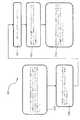
一態様では、本開示は、喫煙物品を提供する。喫煙物品は、一般的に、細長い本体内に設置されたいくつかの構成部品を含むことができ、該細長い本体は、単一の単体シェルであってよいか、または、2つ以上の分離可能な部片で形成することができる。例えば、一実施形態による喫煙製品は、従来のタバコまたは葉巻の形状に似るなど、形状が実質的に管状であってよいシェル(すなわち、細長い本体)を含むことができる。シェル内には、喫煙物品の構成部品の全てが常駐することができる。他の実施形態では、喫煙物品は、接合され、かつ、分離可能である2つのシェルを含むことができる。例えば、制御体が、1つ以上の再使用可能な構成部品を含み、かつ、カートリッジに取り外し可能に装着する端部を有するシェルを含むことができる。カートリッジは、1つ以上の使い捨て構成部品を含み、かつ、制御体に取り外し可能に装着する端部を有するシェルを含むことができる。単一のシェル内のまたは分離可能な制御体およびカートリッジ内の構成部品のより特定の構成は、本明細書で提示する更なる本開示に照らすと明白である。 In one aspect, the present disclosure provides a smoking article. Smoking articles generally may include several components located within an elongated body, which may be a single unitary shell, or two or more separable shells. It can be formed of various pieces. For example, smoking articles according to one embodiment may include a shell (ie, an elongated body) that may be substantially tubular in shape, such as resembling the shape of a conventional cigarette or cigar. Within the shell, all of the components of the smoking article can reside. In other embodiments, smoking articles can include two shells that are joined and separable. For example, the control body may include one or more reusable components and may include a shell having an end that removably mounts to the cartridge. The cartridge may include one or more disposable components and may include a shell having an end that removably attaches to the control body. More specific configurations of components within a single shell or within separable controls and cartridges will be apparent in light of the further disclosure provided herein.
本開示による有用な喫煙物品は、特に、電源(すなわち、電力源)、1つ以上の制御構成部品(例えば、電源から物品の1つ以上の更なる構成部品への電力の流れを制御/起動/調節するため)、加熱器構成部品、およびエアロゾル前駆体構成部品の何らかの組み合わせを含むことができる。喫煙物品は、更に、物品によって生成されたエアロゾルを、ユーザが物品で一服することによって引き出すことができるように物品を通る画定された気流路を含むことができる。物品内の構成部品の整合が変わり得る。特定の実施形態では、エアロゾル前駆体構成部品は、ユーザへのエアロゾル送給を最大化するようにユーザの口の近位側である物品の端部近傍に位置することができる。しかしながら、他の構成は除外されない。一般的に、加熱器構成部品は、加熱器構成部品からの熱がエアロゾル前駆体(ならびに、ユーザへの送給のために同様に供給され得る1つ以上のフレーバー剤、薬など)を蒸発してユーザへの送給に向けてエアロゾルを形成することができるようにそのエアロゾル前駆体構成部品の十分に近傍に位置決めすることができる。加熱部材がエアロゾル前駆体構成部品を加熱すると、エアロゾルは、消費者による吸入に適した物理的形態で形成、放出、または生成される。前出の用語は、放出する、放出している、放出、または、放出されたとの言及は、形成または生成する、形成または生成している、形成または生成する、および形成または生成される、を含むように交換可能であることが意図されることに注意されたい。具体的には、吸入可能な物質は、蒸気またはエアロゾル、またはその混合物の形で放出される。 Smoking articles useful according to the present disclosure, among other things, control/activate the flow of power from a power source (ie, a power source), one or more control components (eg, a power source to one or more additional components of the article). /To adjust), a heater component, and some combination of aerosol precursor components. The smoking article can further include a defined air flow path through the article so that the aerosol produced by the article can be withdrawn by the user by swallowing with the article. The alignment of components within the article can vary. In certain embodiments, the aerosol precursor component may be located near the end of the article, which is proximal to the user's mouth to maximize aerosol delivery to the user. However, other configurations are not excluded. Generally, the heater component vaporizes heat from the heater component to the aerosol precursor (as well as one or more flavoring agents, drugs, etc. that may also be delivered for delivery to the user). And can be positioned sufficiently close to the aerosol precursor component so that the aerosol can be formed for delivery to the user. When the heating member heats the aerosol precursor component, the aerosol is formed, released, or produced in a physical form suitable for inhalation by a consumer. The above terms refer to releasing, releasing, releasing, or released to form or produce, form or produce, form or produce, and form or produce. Note that it is intended to be interchangeable to include. Specifically, the inhalable substance is emitted in the form of a vapor or an aerosol, or a mixture thereof.
本開示による喫煙物品は、一般的に、抵抗加熱、インジケータの電力供給など様々な機能性を物品に提供するのに十分な電流の流れを提供するためにバッテリまたは他の電力源を含むことができる。本発明の喫煙製品の電源は、様々な実施形態で取ることができる。電源は、エアロゾル形成に備えて所望の持続時間にわたる使用を介して物品に電力を供給ために加熱部材を急速に加熱するのに十分な電力を送給することができることが好ましい。電源は、物品内に都合よく収まるようにサイズ設定されることが好ましい。有用な電源の実施例としては、好ましくは充電式である(例えば、充電式リチウム二酸化マンガン電池)リチウムイオン電池が挙げられる。特に、リチウムポリマー電池は、そのようなバッテリとして使用することができ、かつ、安全性を高めることができる。他の形式の電池−例えば、N50−AAA CADNICAニッケル‐カドミウム蓄電池−も使用され得る。本開示により使用することができる電池の尚も更なる実施例が、米国特許出願第2010/0028766号で説明されており、この開示内容は、全体が参照により本明細書に組み入れられる。薄膜電池が、本開示の特定の実施形態に使用され得る。これらの電池のいずれか、または、その組合せを電源において使用することができるが、充電式電池が、使い捨て電池に関連した経費および処分上の検討事項のため好適である。使い捨て電池が提供される実施形態では、喫煙物品は、電池の取り出しおよび交換のためのアクセスを含むことができる。あるいは、充電式電池が使用される実施形態では、喫煙物品は、電力を標準的な120ボルトのAC壁面コンセントから導出する従来の再充填ユニット、または、自動車電気システム、または、USBを含め別個の携帯型電源などの他の電源接続部内の対応する接点との相互作用のために充電接点を含むことができる。電池を再充電する手段は、例えば、喫煙物品内に存在する相対的により小さい電池のために複数の充電を提供することができる相対的に大きい方の電池ユニットを含むことができる携帯型充電ケース内に提供することができる。物品は、更に、物品を外部電源に物理的に接続されることなく充電することができるように非接触誘導充電システムを提供する構成部品を含むことができる。したがって、物品は、物品内の電磁場から充電式電池へのエネルギー伝達を助長する構成部品を含むことができる。 Smoking articles according to the present disclosure may generally include a battery or other power source to provide sufficient current flow to provide various functionality to the article, such as resistance heating, powering indicators, and the like. it can. The smoking article power supply of the present invention can be provided in various embodiments. The power source is preferably capable of delivering sufficient power to rapidly heat the heating member to power the article through use over a desired duration in preparation for aerosol formation. The power source is preferably sized to fit conveniently within the article. Examples of useful power sources include lithium ion batteries, which are preferably rechargeable (eg, rechargeable lithium manganese dioxide batteries). In particular, a lithium polymer battery can be used as such a battery and can increase safety. Other types of batteries-eg N50-AAA CADNICA nickel-cadmium accumulators-may also be used. Still further examples of batteries that can be used in accordance with the present disclosure are described in US Patent Application No. 2010/0028766, the disclosure of which is incorporated herein by reference in its entirety. Thin film batteries may be used in certain embodiments of the present disclosure. Either of these batteries, or a combination thereof, can be used in the power source, but rechargeable batteries are preferred due to the cost and disposal considerations associated with disposable batteries. In embodiments in which a disposable battery is provided, the smoking article may include access for battery removal and replacement. Alternatively, in embodiments where rechargeable batteries are used, the smoking article may be a conventional refill unit that draws power from a standard 120 volt AC wall outlet, or a separate vehicle electrical system or USB. Charging contacts may be included for interaction with corresponding contacts in other power connections, such as portable power supplies. The means for recharging the battery may include, for example, a relatively large battery unit capable of providing multiple charges for the relatively smaller batteries present in the smoking article. Can be provided within. The article can further include components that provide a contactless inductive charging system so that the article can be charged without being physically connected to an external power source. Thus, the article can include components that facilitate energy transfer from electromagnetic fields within the article to the rechargeable battery.
更なる実施形態では、電源は、また、1つ以上のコンデンサを含むことができる。コンデンサは、電池より素早く放電することができ、かつ、パフ間で帯電させることができ、電池は、直接に加熱部材に電力を供給するために使用された場合より低い割合にてコンデンサに放電することができる。例えば、スーパーコンデンサ(すなわち、電気二重層コンデンサ(EDLC))は、電池と別個にまたは組み合わせて使用することができる。単独に使用されたとき、スーパーコンデンサは、物品の毎回の使用の前に再充電され得る。したがって、本開示は、また、スーパーコンデンサを電荷を補給するために使用間で喫煙物品に装着することができる充電器構成部品を含んでよい。 In a further embodiment, the power supply can also include one or more capacitors. Capacitors can discharge faster than batteries and can be charged between puffs, and batteries discharge to the capacitors at a lower rate than if they were used to directly power the heating element. be able to. For example, supercapacitors (ie, electric double layer capacitors (EDLC)) can be used separately or in combination with batteries. When used alone, the supercapacitor can be recharged before each use of the article. Thus, the present disclosure may also include a charger component that may be attached to the smoking article between uses to replenish the supercapacitor.
喫煙物品は、様々な電力管理ソフトウェア、ハードウェアおよび/または他の電子制御構成部品を更に含むことができる。例えば、そのようなソフトウェア、ハードウェアおよび/または電子制御は、電池の充電を実行する、電池充電および放電状態を検出する、省電力動作を行う、電池の偶発的なまたは過剰な放電を防止するなどを含むことができる。 The smoking article may further include various power management software, hardware and/or other electronic control components. For example, such software, hardware and/or electronic controls may perform battery charging, detect battery charging and discharging conditions, perform power saving operations, prevent accidental or excessive battery discharging. Can be included.
本開示による「制御装置」または「制御構成部品」は、本喫煙物品において有用な様々な要素を包含することができる。更に、本開示による喫煙物品は、単体要素内に共存することができるか、または、喫煙物品内の別個の場所に存在することができる1つ、2つ、または、更に多くの制御構成部品を含むことができ、個々の制御構成部品は、異なる制御面を実行するのに利用することができる。例えば、喫煙物品は、電池からの電力放電を制御するように電池と一体かまたはその他の方法で組み合わされる制御構成部品を含むことができる。喫煙物品は、別々に、物品の他の面を制御する制御構成部品を含むことができる。あるいは、物品の複数の制御面または全ての制御面を実行する単一の制御装置が設けられ得る。同様に、物品において使用されるセンサ(例えば、パフセンサ)は、刺激に応答して電源からの電力放電の起動を制御する制御構成部品を含むことができる。喫煙物品は、別々に、物品の他の面を制御する制御成分を含むことができる。あるいは、単一の制御装置は、物品の複数の制御面または全ての制御面を実行するセンサが設けられるか、または、その他の方法で該センサに関連づけられ得る。したがって、制御装置の様々な組合せが、装置の全ての面の所望のレベルの制御を提供するために本喫煙物品において組み合わせられ得ることがわかる。 A “control device” or “control component” according to this disclosure can include various elements useful in the present smoking articles. Further, smoking articles according to the present disclosure may include one, two, or more control components that may co-exist in a single element or be present in discrete locations within the smoking article. Individual control components can be included and can be utilized to implement different control surfaces. For example, smoking articles can include control components that are integrated with or otherwise associated with the battery to control the power discharge from the battery. The smoking article can separately include control components that control other aspects of the article. Alternatively, a single controller may be provided that implements multiple or all control surfaces of the article. Similarly, sensors used in articles (eg, puff sensors) can include control components that control the activation of power discharges from a power source in response to a stimulus. The smoking article can separately include control components that control other aspects of the article. Alternatively, a single controller may be provided with, or otherwise associated with, sensors that implement multiple or all control surfaces of the article. Thus, it will be appreciated that various combinations of control devices may be combined in the present smoking article to provide the desired level of control of all aspects of the device.
喫煙物品は、また、抵抗加熱要素へのなど、物品の更なる構成部品への電源からの電気エネルギーの流れを制御するのに有用な1つ以上の制御装置構成部品を含むことができる。具体的には、物品は、抵抗加熱要素へのなど、電源からの電流の流れを起動させる制御構成部品を含むことができる。例えば、一部の実施形態では、物品は、電力流動の手動制御用制御回路に結び付けることができる押しボタンを含むことができ、消費者は、押しボタンを使用して物品をオンにしおよび/または抵抗加熱要素への電流の流れを起動させることができる。複数のボタンは、物品をオンおよびオフにし、かつ、エアロゾル生成のために加熱を起動させるという手動の実行のために設けることができる。存在する1つ以上の押しボタンは、喫煙物品の外面と実質的に面一であってよい。 The smoking article may also include one or more controller components useful for controlling the flow of electrical energy from a power source to additional components of the article, such as to resistive heating elements. Specifically, the article can include control components that activate the flow of current from a power source, such as to a resistive heating element. For example, in some embodiments, the article can include a push button that can be coupled to a control circuit for manual control of power flow, and the consumer can use the push button to turn on the article and/or The flow of current to the resistive heating element can be activated. Multiple buttons may be provided for manual execution of turning the article on and off and activating heating for aerosol production. The one or more push buttons present may be substantially flush with the outer surface of the smoking article.
押しボタンの代わりに(または、該ボタンに加えて)、本発明の物品は、消費者が物品で一服すること(すなわち、パフによって起動される加熱)に応答する1つ以上の制御構成部品を含むことができる。例えば、物品は消費者が物品で一服する(すなわち、パフを起動するスイッチ)ときに、圧力変化または気流変化に敏感であるスイッチを含むことができる。他の適切な電流起動/起動解除機構部は、温度作動式電源スイッチまたは、リップ圧力スイッチを含むことができる。そのようなパフ−起動能力を提供することができる例示的な機構部としては、イリノイ州フリーポートのHoneywell,Inc.のMicroSwitch Division製造のモデル163PC01D36シリコンセンサが挙げられる。そのようなセンサで、消費者が物品で一服するとき、抵抗加熱要素を圧力の変化によって急速に起動することができる。更に、熱線風力測定原理を用いるものなど、流れ感知装置が、気流の変化を感知した後に十分に急速に抵抗加熱要素の通電に引き起こすために使用され得る。使用され得る更なるパフ起動式スイッチは、フロリダ州ローダーデールのMicro Pneumatic Logic,Inc.製モデルNo.MPL−502−V、レンジAなど、圧力差スイッチである。別の好適なパフ起動式機構部は、所定の閾値圧を検出する比較器と更に結合される感圧トランスデューサ(例えば、増幅器または利得段階が装備)である。更に別の好適なパフ起動式機構部は、気流によって偏向される羽根であり、該羽根の動作は、移動感知手段によって検出される。更に別の好適な起動機構部は、圧電スイッチである。また、好適に接続される、イリノイ州フリーポートのHoneywell、Inc.Freeport、MicroSwitch Division製Honeywell MicroSwitch Microbridge Airflow Sensor、Part No.AWM 2100Vが有用である。本開示による加熱回路において採用され得る需要作動式電気スイッチの更なる実施例が、Gerthらの米国特許第4,735,217号で説明されており、この特許は、全体が参照により本明細書に組み入れられる。他の好適な差動スイッチ、アナログ圧力センサ、流量センサなどが、本開示の知見で当業者に明らかであろう。喫煙物品内のパフ起動式スイッチと気流路との間の流体接続をもたらす圧力検知管または他の流路を、一服中の圧力変化が難なくスイッチによって特定されるように含むことができる。本喫煙物品において有用であってよいマイクロコントローラを含め、電流調節回路および他の制御構成部品の更なる説明が、全てBrookらの米国特許第4,922,901号、同第4,947,874号および同第4,947,875号と、McCaffertyらの米国特許第5,372,148号と、Fleischhauerらの米国特許第6,040,560号と、Nguyenらの米国特許第7,040,314号とで提示されており、これらの特許の全ては、参照により本明細書に全体が組み入れられる。 Instead of (or in addition to) a push button, the articles of the present invention include one or more control components responsive to a consumer taking a dose of the article (ie, heating triggered by a puff). Can be included. For example, the article can include a switch that is sensitive to pressure or air flow changes when the consumer takes a dose with the article (ie, the switch that activates the puff). Other suitable current activation/deactivation mechanisms may include a temperature actuated power switch or lip pressure switch. Exemplary mechanics that can provide such puff-activating capability include Honeywell, Inc. of Freeport, Illinois. Model 163PC01D36 silicon sensor manufactured by MicroSwitch Division. With such a sensor, the resistance heating element can be rapidly activated by a change in pressure when the consumer has a dose of goods. Further, a flow sensing device, such as one using the hot wire anemometry principle, can be used to trigger the energization of the resistive heating element sufficiently quickly after sensing a change in air flow. A further puff activated switch that may be used is Micro Pneumatic Logic, Inc. of Lauderdale, Florida. Model No. It is a pressure difference switch such as MPL-502-V and range A. Another suitable puff actuated mechanism is a pressure sensitive transducer (e.g. equipped with an amplifier or gain stage) that is further coupled with a comparator that detects a predetermined threshold pressure. Yet another suitable puff actuated mechanism is a vane deflected by air flow, the movement of which is detected by movement sensing means. Yet another suitable actuating mechanism is a piezoelectric switch. Also, preferably connected to Honeywell, Inc. of Freeport, Illinois. Freeport, Honeywell MicroSwitch Microbridge Airflow Sensor, Micro Switch Division Part No. AWM 2100V is useful. A further example of a demand actuated electrical switch that may be employed in a heating circuit according to the present disclosure is described in Gerth et al., US Pat. No. 4,735,217, which is hereby incorporated by reference in its entirety. Be incorporated into. Other suitable differential switches, analog pressure sensors, flow sensors, etc. will be apparent to one of ordinary skill in the art in view of the present disclosure. A pressure sensing tube or other flow path that provides a fluid connection between the puff actuated switch in the smoking article and the air flow path can be included so that pressure changes during a dose are easily identified by the switch. For a further description of current regulation circuits and other control components, including a microcontroller that may be useful in the present smoking articles, see, Brook et al., US Pat. Nos. 4,922,901 and 4,947,874. And US Pat. No. 4,947,875; McCafferty et al., US Pat. No. 5,372,148; Fleischauer et al., US Pat. No. 6,040,560; and Nguyen et al., US Pat. No. 314, and all of these patents are incorporated herein by reference in their entirety.
特に、容量性感知構成部品は、装置の1つ以上の構成部品について異なる形式の「電源投入」および/または「電源切断」を可能にするために様々な方法で装置に組み込むことができる。容量感知は、近接、位置、または、変位、湿度、流体液位、圧力、または、加速を検出および/または測定するセンサを含むがこれらに限定されない、容量性結合を基本とする技術を組み込む任意のセンサの使用を含むことができる。容量感知は、表面容量、計画容量、相互容量、または、自己容量に備える電子部品から生じる可能性がある。静電容量センサは、概ね、導電であるか、または、空気のそれと異なる絶縁体を有するものは何でも検出することができる。静電容量センサでは、例えば、機械式ボタン(すなわち、先に参照した押しボタンスイッチ)を容量代替物と入れ替えることができる。したがって、本開示による容量感知の1つの特定の用途布は、接触静電容量センサである。例えば、ユーザが様々なコマンドを入力することを可能にするタッチパッドが、喫煙製品に存在することができる。最も基本的に、タッチパッドは、既に先述したように、押しボタンとほぼ同じように発熱体に電力を供給することに備えることができる。他の実施形態では、容量感知は、物品を利用するために喫煙物品上の唇の圧力が装置に発熱体に電力を供給するように報せることができるように喫煙物品の口端部近傍で適用することができる。接触容量センサに加えて、運動容量センサ、液体容量センサ、および、加速度計を、喫煙物品からの様々な応答を違法ために本開示により利用することができる。更に、光電感知器を、また、本発明の喫煙製品に組み込むことができる。 In particular, the capacitive sensing components can be incorporated into the device in various ways to allow different types of "power up" and/or "power down" for one or more components of the device. Capacitive sensing includes any technology that incorporates capacitive coupling based techniques including, but not limited to, sensors for detecting and/or measuring proximity, position or displacement, humidity, fluid level, pressure or acceleration. Use of sensors of Capacitive sensing can result from electronic components providing surface capacitance, planned capacitance, mutual capacitance, or self-capacitance. Capacitive sensors are generally capable of detecting anything that is electrically conductive or has an insulator different from that of air. In a capacitive sensor, for example, a mechanical button (ie, the push button switch referred to above) can be replaced with a capacitive alternative. Thus, one particular application fabric for capacitive sensing according to the present disclosure is a contact capacitance sensor. For example, a touch pad may be present on a smoking product that allows a user to enter various commands. Most basically, a touchpad can be equipped to power a heating element much like a push button, as already mentioned above. In another embodiment, capacitive sensing is provided near the mouth end of the smoking article so that lip pressure on the smoking article to utilize the article can signal the device to power a heating element. Can be applied. In addition to contact capacitive sensors, motion capacitive sensors, liquid capacitive sensors, and accelerometers can be utilized by the present disclosure to illegally respond to various responses from smoking articles. Moreover, photoelectric detectors can also be incorporated into the smoking articles of the present invention.
本物品において利用されるセンサは、エアロゾル前駆体材料を含む基材を加熱してユーザによる吸入に向けて蒸気またはエアロゾルを形成するために発熱体への電力潮流の合図を明示的にすることができる。センサは、また、更なる機能を提供することができる。例えば、「スリープ解除」センサを含むことができる。類似の機能を提供する他の感知方法を本開示により同様に利用することができる。 The sensor utilized in the present article can explicitly signal a power flow to a heating element to heat a substrate containing an aerosol precursor material to form a vapor or aerosol for inhalation by a user. it can. The sensor can also provide additional functionality. For example, a "wake-up" sensor can be included. Other sensing methods that provide similar functionality can be utilized by the present disclosure as well.
消費者が喫煙物品の口端部を利用するとき、電流起動手段は、急速に熱を生成するために抵抗加熱部材を通る電流の無制限のまたは中断されない流れを可能にすることができる。急速な加熱のため、(i)抵抗素子の加熱、および、該素子による経験された温度を制御するために、加熱部材を通る電流の流れを調節し、かつ、(ii)基材、または、エアゾール前駆体材料および/または他の香りまたは吸入可能な材料を担持する他の構成部品の過熱および劣化を防止するために電流調節構成部品を含むことが有用であってよい。 When a consumer utilizes the mouth end of a smoking article, the current activation means may allow an unlimited or uninterrupted flow of current through the resistive heating member to rapidly generate heat. For rapid heating, (i) heating the resistive element and controlling the flow of current through the heating element to control the temperature experienced by the element, and (ii) the substrate, or It may be useful to include a current regulating component to prevent overheating and deterioration of the aerosol precursor material and/or other components carrying other scents or inhalable materials.
電流調節回路は、特に時間基準であってよい。具体的には、一態様では、このような回路は、一服中に初期期間にわたって発熱体を通る中断されない電流の流れを可能にする手段と、一服が完了されるまで電流の流れをその後調節するタイマー手段とを含む。例えば、その後の調節は、発熱体を所望の温度範囲内に維持するために、電流の流れの迅速な(例えば、約1〜50ミリ秒毎台)オン/オフの切り替えを含むことができる。更に、調節は、その後、電流の流れを完全にオフにして所望の温度が、達成されるまで、単に中断されない電流の流れを可能にすることを含むことができる。加熱部材は、消費者が、物品上で別のパフを開始する(または、加熱器を起動させるために採用される特定のスイッチ実施形態によって押しボタンを手作業で起動させる)によって再起動され得る。あるいは、その後の調節は、発熱体を所望の温度範囲内に維持するために発熱体を通る電流の流れの変調を伴うことができる。一部の実施形態では、吸入可能な物質の所望の投与を放出するために、加熱部材は、約0.2秒〜約5.0秒、約0.3秒〜約4.5秒、約0.5秒〜約4.0秒、約0.5秒〜約3.5秒、または、約0.6秒〜約3.0秒の持続時間で通電することができる。1つの例示的な時間基準電流調節回路は、トランジスタ、タイマー、比較器、およびコンデンサを含むことができる。好適なトランジスタ、タイマー、比較器、およびコンデンサが市販されており、当業者に明らかであろう。例示的なタイマーが、NEC ElectronicsからC−1555Cとして、General Electric Intersil,Inc.からICM7555として、並びに、いわゆる「555のタイマー」の様々な他のサイズおよび構成として販売されている。例示的な比較器は、LM311としてNational Semiconductorから販売されている。本喫煙物品において有用であってよいそのような時間基準電流調節回路および他の制御構成部品の更なる説明が、全てBrooksらの米国特許第4,922,901号、同第4,947,874号、および同第4,947,875号で提示されており、これらの特許の全ては、参照により本明細書に全体が組み入れられる。 The current regulation circuit may be time-based in particular. Specifically, in one aspect, such a circuit provides a means for allowing uninterrupted current flow through the heating element during an initial period during a dose and then regulates the current flow until the dose is completed. And timer means. For example, subsequent conditioning can include rapid on/off switching of current flow (e.g., on the order of about every 1-50 milliseconds) to keep the heating element within a desired temperature range. Further, the conditioning can then include turning off the current flow completely to allow only uninterrupted current flow until the desired temperature is achieved. The heating member may be reactivated by the consumer initiating another puff on the article (or manually activating a push button by the particular switch embodiment employed to activate the heater). .. Alternatively, subsequent conditioning can involve modulation of the flow of current through the heating element to maintain it within the desired temperature range. In some embodiments, the heating member has about 0.2 seconds to about 5.0 seconds, about 0.3 seconds to about 4.5 seconds, about 0.3 seconds to about 4.5 seconds to release the desired dose of inhalable substance. Power can be energized for a duration of 0.5 seconds to about 4.0 seconds, about 0.5 seconds to about 3.5 seconds, or about 0.6 seconds to about 3.0 seconds. One exemplary time reference current adjustment circuit can include transistors, timers, comparators, and capacitors. Suitable transistors, timers, comparators, and capacitors are commercially available and will be apparent to those skilled in the art. An exemplary timer is available from NEC Electronics as C-1555C, General Electric Intersil, Inc. From ICM7555, as well as various other sizes and configurations of the so-called "555 Timer". An exemplary comparator is sold as LM311 by National Semiconductor. For a further description of such time reference current regulation circuits and other control components that may be useful in the present smoking articles, see Brooks et al., US Pat. Nos. 4,922,901 and 4,947,874. No. 4,947,875, all of which are incorporated herein by reference in their entirety.
制御構成部品は、特に、抵抗加熱要素に提供される熱量を綿密に制御するように構成することができる。一部の実施形態では、定義された温度が達成されると、電流調節構成部品は抵抗加熱要素への電流の流れを停止するように機能することができる。そのような定義された温度は、別の方法で本明細書で論じるように、エアロゾル前駆体材料および任意の更なる吸入可能な物質を蒸発させて従来のタバコ上の典型的なパフと同等の量のエアロゾルを供給するのに十分に実質的に高い範囲にあり得る。単一のパフの所望の容積を供給するために十分な容積でエアロゾル前駆体材料を蒸発させるために必要とされる熱は変わり得るが、加熱部材が、約120℃またはそれ以上、約130℃またはそれ以上、約140℃またはそれ以上、または、約160℃の温度まで加熱することが特に有用であってよい。一部の実施形態では、適切な量のエアロゾル前駆体材料を蒸発させるために、加熱温度は、約180℃またはそれ以上、約200℃またはそれ以上、約300℃またはそれ以上、または約350℃またはそれ以上であってよい。更なる実施形態では、エアロゾル形成のための定義された温度は、約120℃〜約350℃、約140℃〜約300℃、または、約150℃〜約250℃であってよい。加熱の温度および時間は、制御ハウジング内に含まれた1つ以上の構成部品によって制御することができる。定義された温度が定義された期間で定義された温度を維持するように達成されると、電流調節構成部品は、同様に、抵抗加熱要素への電流をサイクル動作にて入切りさせることができる。 The control component may be specifically configured to closely control the amount of heat provided to the resistive heating element. In some embodiments, the current regulation component can function to stop the flow of current to the resistive heating element once the defined temperature is reached. Such a defined temperature evaporates the aerosol precursor material and any additional inhalable material, as discussed elsewhere herein, to be comparable to a typical puff on a conventional cigarette. It can be in a range substantially high enough to deliver an amount of aerosol. The heat required to evaporate the aerosol precursor material in a sufficient volume to provide the desired volume of a single puff may vary, but the heating member may be about 120° C. or higher, about 130° C. It may be particularly useful to heat to temperatures of about 140° C. or higher, about 140° C. or higher, or about 160° C. In some embodiments, the heating temperature is about 180° C. or higher, about 200° C. or higher, about 300° C. or higher, or about 350° C. in order to evaporate a suitable amount of aerosol precursor material. Or more. In further embodiments, the defined temperature for aerosol formation may be about 120°C to about 350°C, about 140°C to about 300°C, or about 150°C to about 250°C. The temperature and time of heating can be controlled by one or more components contained within the control housing. When the defined temperature is achieved to maintain the defined temperature for a defined period of time, the current regulation component can also cycle the current to and from the resistive heating element. ..
尚も更に、電流調節構成部品は、エアロゾル形成温度を下回る第1の温度を維持するために抵抗加熱要素への電流をサイクル動作にて入切りさせることができ、その後、第1の温度を上回り、かつ、エアロゾル形成温度である第2の温度を達成するように、電流起動制御構成部品に応答して電流の流れの増大を可能にすることができる。そのような制御は、エアロゾル形成が消費者によるパフの開始でほとんど即座に始まるようにエアロゾル形成の物品の応答時間を向上させることができる。一部の実施形態では、第1の温度(待機温度と特徴づけることができる)は、先に定義されたエアロゾル形成温度を若干下回るにすぎない可能性がある。具体的には、待機温度は、約50℃〜約150℃、約70℃〜約140℃、約80℃〜約120℃、または約90〜約110℃であってよい。 Still further, the current regulating component may cycle current into and out of the resistive heating element to maintain the first temperature below the aerosol formation temperature, after which the first temperature is exceeded. , And may allow increased current flow in response to the current activation control component to achieve the second temperature, which is the aerosol formation temperature. Such control can improve the response time of the aerosol-forming article so that the aerosol formation begins almost immediately upon initiation of the puff by the consumer. In some embodiments, the first temperature (which may be characterized as the standby temperature) may be just below the aerosol formation temperature defined above. Specifically, the standby temperature may be from about 50°C to about 150°C, about 70°C to about 140°C, about 80°C to about 120°C, or about 90 to about 110°C.
上記の制御素子に加えて、喫煙物品は、また、1つ以上のインジケータを含んでよい。そのようなインジケータは、本発明の物品の使用の複数の態様の表示を提供することができる照明部(例えば、発光ダイオード)であってよい。更に、LEDインジケータは、従来のタバコがユーザによって火が付けられて一服されるときに見られる体色変化をシミュレートするために喫煙物品の遠位端にて位置決めされ得る。動作の他の指数が、また、包含される。例えば、視覚インジケータは、また、喫煙経験の進行を示すために光の色または強度の変化を含んでよい。触覚型のインジケータおよび音によるインジケータが、同様に、本開示により包含される。更に、そのようなインジケータの組合せが、また、単一の物品において使用され得る。 In addition to the control elements described above, smoking articles may also include one or more indicators. Such an indicator may be a lighting unit (eg, a light emitting diode) that can provide an indication of multiple aspects of use of the article of the present invention. Further, an LED indicator may be positioned at the distal end of the smoking article to simulate the body color change seen when a conventional cigarette is lit by the user and swallowed. Other indices of motion are also included. For example, the visual indicator may also include a change in light color or intensity to indicate the progress of the smoking experience. Haptic and audible indicators are also encompassed by this disclosure. Moreover, a combination of such indicators may also be used in a single article.
本開示による喫煙物品は、更に、ユーザによる吸入に備えてエアロゾルを生成するためにエアロゾル前駆体構成部品を加熱する加熱部材を含むことができる。様々な実施形態では、加熱部材は、電流が該部材に適用されたときに抵抗加熱を提供する材料で形成することができる。抵抗加熱要素は、電流が該要素を通って流れたときに抵抗加熱要素を十分な量の熱を供給するのに有用にする電気抵抗を示すことが好ましい。エアロゾル前駆体構成部品/組成を有する加熱部材の相互作用は、例えば、熱伝導、熱放射および/または熱対流を介してであってよい。 Smoking articles according to the present disclosure may further include a heating member that heats the aerosol precursor component to produce an aerosol for inhalation by a user. In various embodiments, the heating member can be formed of a material that provides resistive heating when an electric current is applied to the member. The resistive heating element preferably exhibits an electrical resistance that makes the resistive heating element useful for supplying a sufficient amount of heat when an electric current is passed therethrough. The interaction of the heating element with the aerosol precursor component/composition may be, for example, via heat conduction, heat radiation and/or heat convection.
抵抗発熱体として有用な導電材は、低質量、低密度および中程度の抵抗率を有し、かつ、使用中に経験される温度にて熱的に安定であるものであってよい。有用な発熱体は、急速に加熱および冷却し、したがってエネルギー利用の効率化に備える。要素の急速な加熱は、該要素に近接してエアロゾル前駆体材料のほとんど即座の揮発を提供する上で有益であってよい。急速冷却(すなわちエアロゾル前駆体成分/組成/材料の蒸発温度を下回る温度まで)は、エアロゾル形成が望まれない期間中にエアロゾル前駆体材料の実質的な蒸発(したがって浪費)を防止する。特に時間基準電流制御が採用されるとき、そのような発熱体は、また、エアロゾル前駆体材料が経験した温度範囲の相対的に正確な制御を可能にする。有用な導電材は、好ましくは、エアロゾルの香りまたは含有量に悪影響を与えないように加熱されている材料(例えば、エアロゾル前駆体材料および他の吸入可能な実質材料)、または、生成される蒸気とは化学的に反応しない。導電材として使用されていることができる例示的な非限定的な材料としては、炭素、黒鉛、炭素/黒鉛複合物、金属、金属および非金属炭化物、窒化物、珪化物、金属間化合物、サーメット、金属合金および金属箔が挙げられる。特に、耐火物が、有用であってよい。様々な異なる材料を、抵抗率、質量および熱伝導度の所望の特性を達成するために混合することができる。特定の実施形態では、利用することができる金属としては、例えば、ニッケル、クロミウム、ニッケルおよびクロミウム(例えば、ニクロム)の合金,および鋼が挙げられる。抵抗加熱を提供するのに有用であってよい材料が、カウントらの米国特許第5,060,671号と、Deeviらの米国特許第5,093,894号と、Deeviらの米国特許第5,224,498号と、Sprinkel Jr.らの米国特許第5,228,460号と、Deeviらの米国特許第5,322,075号と、Deeviらの米国特許第5,353,813号と、Deeviらの米国特許第5,468,936号と、Dasの米国特許第5,498,850号と、Dasの米国特許第5,659,656号と、Deeviらの米国特許第5,498,855号と、Hajaligolの米国特許第5,530,225号と、Hajaligolに米国特許第5,665,262号と、Dasらの米国特許第5,573,692号と、および、Fleischhauerらの米国特許第5,591,368号とで説明されており、これらの特許の全ては、参照により本明細書に全体が組み入れられる。 Conductive materials useful as resistance heating elements may be those that have low mass, low density and moderate resistivity and that are thermally stable at the temperatures experienced during use. Useful heating elements heat and cool rapidly, thus providing for efficient energy utilization. Rapid heating of the element may be beneficial in providing near immediate vaporization of the aerosol precursor material in proximity to the element. Rapid cooling (i.e., below the vaporization temperature of the aerosol precursor component/composition/material) prevents substantial vaporization (and thus wasting) of the aerosol precursor material during periods when aerosol formation is not desired. Such a heating element also allows relatively precise control of the temperature range experienced by the aerosol precursor material, especially when time-based current control is employed. Useful conductive materials are preferably materials that have been heated so as not to adversely affect the scent or content of the aerosol (eg, aerosol precursor materials and other inhalable bulk materials), or the vapor produced. Does not react chemically with. Exemplary non-limiting materials that can be used as the conductive material include carbon, graphite, carbon/graphite composites, metals, metal and non-metal carbides, nitrides, silicides, intermetallics, cermets. , Metal alloys and metal foils. In particular, refractories may be useful. A variety of different materials can be mixed to achieve the desired properties of resistivity, mass and thermal conductivity. In certain embodiments, the metals that can be utilized include, for example, nickel, chromium, alloys of nickel and chromium (eg, nichrome), and steel. Materials that may be useful in providing resistive heating include Count et al., US Pat. No. 5,060,671, Deevi et al., US Pat. No. 5,093,894, and Deevi et al., US Pat. , 224, 498 and Srinkel Jr. U.S. Pat. No. 5,228,460, Deevi et al., U.S. Pat. No. 5,322,075, Deevi et al., U.S. Pat. No. 5,353,813, and Deevi et al., U.S. Pat. ,936, Das U.S. Pat. No. 5,498,850, Das U.S. Pat. No. 5,659,656, Deevi et al. U.S. Pat. No. 5,498,855, and Hajaligol U.S. Pat. 5,530,225; Hajaligol, US Pat. No. 5,665,262; Das et al., US Pat. No. 5,573,692; and Fleischauer et al., US Pat. No. 5,591,368. And all of these patents are incorporated herein by reference in their entirety.
抵抗加熱要素は、箔、発泡体、ディスク、螺旋、繊維、ワイヤ、フィルム、糸、ストリップ、リボン、または、円柱体の形態において、並びに、異なる寸法の異形など、様々な形態で提供することができる。一部の実施形態では、本開示による抵抗加熱要素は、2012年3月28日出願の同時係属中の米国特許出願第13/432,406号で説明されているようになど、導電基材であり得、この開示内容は、全体が参照により本明細書に組み入れられる。抵抗加熱要素は、また、2012年9月4日出願の同時係属中の米国特許出願第13/602,871号で説明されているようになど、マイクロヒータ構成部品の一部として存在することができ、この開示内容は、全体が参照により本明細書に組み入れられる。 The resistive heating element may be provided in various forms such as in the form of foils, foams, discs, spirals, fibers, wires, films, threads, strips, ribbons or cylinders, as well as variants of different dimensions. it can. In some embodiments, a resistive heating element according to the present disclosure is made of a conductive substrate, such as as described in co-pending US patent application Ser. No. 13/432,406 filed March 28, 2012. This disclosure is possible and is hereby incorporated by reference in its entirety. The resistive heating element may also be present as part of a microheater component, such as as described in co-pending US patent application Ser. No. 13/602,871, filed September 4, 2012. Yes, the disclosure of which is incorporated herein by reference in its entirety.
有益なことに、抵抗加熱要素は、発熱体をエアロゾル前駆体材料と密接してまたは該材料に極めて近接して位置決めする(すなわち、熱を、例えば、伝導、放射、または対流を介してエアロゾル前駆体材料に供給する)ことを可能にする形で提供することができる。他の実施形態では、抵抗加熱要素は、エアロゾル前駆体材料がエアロゾル化のために抵抗加熱要素に送給されることができるような形で設置することができる。そのような送給は、抵抗加熱要素へのエアロゾル前駆体の吸い上げ、および、弁流量調節を含んでよい、エアロゾル前駆体を抵抗加熱要素に流すこと(毛細管を介してなど)など様々な実施形態で必要とされる可能性がある。この点を踏まえて、エアロゾル前駆体材料は、時期尚早のエアロゾル化を防止するために抵抗加熱要素から十分に離れて位置決めされるが、エアロゾル化のための抵抗加熱要素への所望量でのエアロゾル前駆体材料の移送を容易にするために抵抗加熱要素の十分に近くに位置決めされる1つ以上のリザーバ内に液体の形で提供され得る。 Beneficially, the resistive heating element positions the heating element in close proximity to, or in close proximity to, the aerosol precursor material (ie, heat is delivered to the aerosol precursor via, for example, conduction, radiation, or convection). Can be provided to the body material). In other embodiments, the resistance heating element can be installed in such a manner that the aerosol precursor material can be delivered to the resistance heating element for aerosolization. Such delivery may include wicking of the aerosol precursor to the resistance heating element, and valving flow regulation, such as flowing the aerosol precursor to the resistance heating element (such as via a capillary), various embodiments, etc. May be needed in. With this in mind, the aerosol precursor material is positioned far enough away from the resistance heating element to prevent premature aerosolization, but at the desired amount of aerosol to the resistance heating element for aerosolization. It may be provided in liquid form in one or more reservoirs positioned sufficiently close to the resistive heating element to facilitate transfer of the precursor material.
特定の実施形態では、本開示による喫煙物品は、タバコ、タバコ成分、または、タバコ由来材料(すなわち、直接にタバコから隔離され得るかまたは合成しいて調製され得るタバコにおいて本来見つかる材料)を含むことができる。採用されるタバコは、熱気送管乾燥タバコ、バーレータバコ、オリエンタルタバコまたはメリーランドタバコ、ダークタバコ、ダーク火熱乾燥タバコ、およびルスティカタバコ、ならびに他の希少なまたは特別なタバコ、またはこれらのブレンドなどのタバコを含むことができるか、または、該タバコから導出され得る。様々な代表的なタバコ形式、加工した形式のタバコおよびタバコブレンドの形式が、ローソンらの米国特許第4、836、224号と、Perfettiらの米国特許第4,924,888号と、ブラウンらの米国特許第5,056,537号と、Brinkleyらの米国特許第5,159,942号と、Gentryの米国特許第5,220,930号と、Blakleyらの米国特許第5,360,023号と、Shaferらの米国特許第6,701,936号と、Dominguezらの米国特許第6,730,832号と、Liらの米国特許第7,011,096号と、Liらの米国特許第7,017,585号と、ローソンらの米国特許第7,025,066号と、Perfettiらの米国特許出願公開第2004/0255965号と、Beremanらの国際公開第02/37990号と、Bombick et al、Fund.Appl.Toicol.39、p.11−17(1997)とで説明されており、これらの全ては、参照により本明細書に全体が組み入れられる。 In certain embodiments, smoking articles according to the present disclosure comprise tobacco, tobacco components, or tobacco-derived materials (ie, materials that are naturally found in tobacco that can be isolated from tobacco directly or prepared synthetically). You can The cigarettes employed include hot air tube dried tobacco, Burley tobacco, Oriental tobacco or Maryland tobacco, dark tobacco, dark fire dried tobacco, and rustica tobacco, as well as other rare or special tobaccos, or blends thereof. It may include or may be derived from tobacco. Various representative tobacco formats, modified formats of tobacco and tobacco blend formats are described in Lawson et al., US Pat. No. 4,836,224, Perfetti et al., US Pat. No. 4,924,888, and Brown et al. U.S. Pat. No. 5,056,537, Brinkley et al. U.S. Pat. No. 5,159,942, Gentry U.S. Pat. No. 5,220,930, and Blakeley et al. U.S. Pat. No. 5,360,023. , Shafer et al., US Pat. No. 6,701,936, Dominguez et al., US Pat. No. 6,730,832, Li et al., US Pat. No. 7,011,096, and Li et al. No. 7,017,585; Lawson et al., US Pat. No. 7,025,066; Perfetti et al., US Patent Application Publication No. 2004/0255965; Bereman et al., WO 02/37990; Bombick. et al, Fund. Appl. Toicol. 39, p. 11-17 (1997), all of which are incorporated herein by reference in their entirety.
喫煙製品内に組み込まれるタバコは、様々な形態において採用され得、タバコの様々な形態の組み合わせが採用され得るか、または、異なる形のタバコが、喫煙製品内の異なる場所にて採用され得る。例えば、タバコは、タバコエキスの形で採用され得る。例えば、Cantrellらの米国特許第7,647,932、Robinsonらの米国特許第8,079,371号と、Crooksらの米国特許出願公開第2007/0215167号とを参照されたく、これらの全ては、参照により本明細書に全体が組み入れられる。 Tobacco incorporated within smoking products may be employed in various forms, combinations of various forms of tobacco may be employed, or different shaped cigarettes may be employed at different locations within the smoking product. For example, tobacco can be employed in the form of tobacco extract. See, for example, US Pat. No. 7,647,932 to Cantrell et al., US Pat. No. 8,079,371 to Robinson et al., and US Pat. , Hereby incorporated by reference in their entirety.
喫煙物品では、従来使用される形式のタバコ添加物をタバコ製品の製造に組み込むことができる。それらの添加物は、葉巻、タバコ、パイプ、などの生産に使用されたタバコの香味を高めるために使用される材料の形式を含むことができる例えば、それらの添加物としては、様々なタバコケーシングおよび/または最上層成分を挙げることができる。例えば、Wochnowskiらの米国特許第3,419,015号と、Berndtらの米国特許第4,054,145号と、Burcham,Jr.らの米国特許第4,887,619号と、Watsonの米国特許第5,022,416号と、Strangらの米国特許第5,103,842号と、Martinの米国特許第5,711,320号とを参照されたく、これらの全ては、参照により本明細書に全体が組み入れられる。好適なケーシング材料としては、水、砂糖および濃縮糖液(例えば、蔗糖、グルコースおよび高フルクトーストウモロコシシロップ)、湿潤薬(例えば、グリセリン、または、プロピレングリコール)、および賦香剤(例えば、ココアおよびカンゾウ)が挙げられる。それらの添加される成分は、また、最上層材料(例えば、メントールなど着香材)を含む。例えば、Maysらの米国特許第4,449,541号を参照されたく、この開示内容は、全体が参照により本明細書に組み入れられる。添加することができる更なる材料としては、ローソンらの米国特許第4,830,028号と、Marshallらの米国特許出願公開第2008/0245377号とで開示されたものが挙げられ、これらの全ては、参照により本明細書に全体が組み入れられる。 In smoking articles, conventionally used types of tobacco additives can be incorporated into the manufacture of tobacco products. The additives may include the form of materials used to enhance the flavor of tobacco used in the production of cigars, tobacco, pipes, etc. For example, those additives include various tobacco casings. And/or top layer components may be mentioned. See, for example, U.S. Pat. No. 3,419,015 to Wochnowski et al., U.S. Pat. No. 4,054,145 to Berndt et al., Burcham, Jr. Et al., US Pat. No. 4,887,619, Watson, US Pat. No. 5,022,416, Strang et al., US Pat. No. 5,103,842, and Martin US Pat. No. 5,711,320. , All of which are incorporated herein by reference in their entirety. Suitable casing materials include water, sugar and concentrated sugar solutions (eg sucrose, glucose and high fructose corn syrup), wetting agents (eg glycerin or propylene glycol), and flavoring agents (eg cocoa and liquorice). ) Is mentioned. The added ingredients also include top layer materials (eg, flavoring agents such as menthol). See, for example, Mays et al., US Pat. No. 4,449,541, the disclosure of which is incorporated herein by reference in its entirety. Additional materials that can be added include those disclosed in Lawson et al., U.S. Pat. No. 4,830,028 and Marshall et al., U.S. Patent Application Publication No. 2008/0245377, all of which are incorporated herein by reference. Are incorporated herein by reference in their entirety.
タバコを喫煙物品、および、特にそれらの喫煙物品内で目的を持ってタバコの実際上全ては燃焼させないように設計される喫煙物品へ組み込む様々な流儀および方法が、Brooksらの米国特許第4,947,874号と、Cantrellらの米国特許第7,647,932と、Robinsonらの米国特許第8,079,371号と、Banerjeeらの米国特許出願公開第2005/0016549号と、Crooksらの米国特許出願公開第2007/0215167号とで説明されており、これらの全ては、参照により本明細書に全体が組み入れられる。 Various manners and methods of incorporating tobacco into smoking articles, and in particular into smoking articles designed to purposefully not burn substantially all of the tobacco within those smoking articles, are described in US Pat. 947,874; Cantrell et al., US Pat. No. 7,647,932; Robinson et al., US Pat. No. 8,079,371; Banerjee et al., US Patent Application Publication 2005/0016549; No. 2007/0215167, all of which are incorporated herein by reference in their entirety.
更なるタバコ材料は、タバコアロマオイル、タバコエッセンス、噴霧乾燥タバコエキス、凍結乾燥タバコエキス、タバコダストなど蒸気前駆体またはエアロゾル前駆体組成内に含められ得る。本明細書で使用するとき、用語「タバコエキス」は、タバコ抽出加工条件および技術を用いてタバコから分離、除去、または導出される成分を意味する。タバコの精製された抽出物、または、他の植物性薬品が、特に使用され得る。典型的には、タバコエキスは、水性性質(例えば、水)、または、有機溶剤(例えば、エタノールなどアルコール類、または、ヘキサンなどアルカン類など)を有する溶媒など、溶媒を使用して取得される。この点を踏まえて、抽出されたタバコ成分は、タバコから除去されて抽出前のタバコ成分から分離され、溶媒内に存在する抽出されたタバコ成分については、(i)溶媒は、抽出されたタバコ成分から除去することができるか、または、(ii)抽出されたタバコ成分および溶媒の混合物をそのようなものとして使用することができる。タバコエキス、タバコエッセンス、溶媒、タバコ抽出加工条件および技術、および、タバコエキス回収および隔離手順の例示的な形式が、Schachnerらのオーストラリア特許第No.276,250号と、Meriroらの米国特許第2,805,669号と、Greenらの米国特許第3,316,919号と、Tughanの米国特許第3,398,754号と、Rookerの米国特許第3,424,171号と、Luttichの米国特許第3,476,118号と、Osborneの米国特許第4,150,677号と、Kiteに米国特許第4,131,117号と、Mullerの米国特許第4,506,682号と、Robertsらの米国特許第4,986,286号と、Faggの米国特許第5,005,593号と、Faggの米国特許第5,065,775号と、Whiteらの米国特許第5,060,669号と、Whiteらの米国特許第5,074,319号と、Whiteらの米国特許第5,099,862号と、Whiteらの米国特許第5,121,757号と、Munozらの米国特許第5,131,415号と、Smithらの米国特許第5,230,354号と、Sensabaughの米国特許第5,235,992号と、Smithの米国特許第5,243,999号と、Raymondの米国特許第5,301,694号と、Gonzalez−Parraらの米国特許第5,318,050号と、Clappらの米国特許第5,435,325号と、Brinkleyらの米国特許第5,445,169号とで説明されており、これらの全ては、参照により本明細書に全体が組み入れられる。 Further tobacco materials may be included within the vapor precursor or aerosol precursor composition such as tobacco aroma oil, tobacco essence, spray dried tobacco extract, freeze dried tobacco extract, tobacco dust and the like. As used herein, the term "tobacco extract" means an ingredient that is separated from, removed from, or derived from tobacco using tobacco extraction processing conditions and techniques. Purified extracts of tobacco or other botanicals may be used in particular. Tobacco extracts are typically obtained using a solvent, such as a solvent having aqueous properties (eg, water) or organic solvents (eg, alcohols such as ethanol or alkanes such as hexane). .. In light of this point, the extracted tobacco component is removed from the tobacco and separated from the pre-extracted tobacco component, and for the extracted tobacco component present in the solvent, (i) the solvent is the extracted tobacco component. It can be removed from the ingredients, or (ii) a mixture of extracted tobacco ingredients and solvent can be used as such. Tobacco extracts, tobacco essences, solvents, tobacco extraction processing conditions and techniques, and exemplary forms of tobacco extract recovery and sequestration procedures are described in Schachner et al., Australian Patent No. 276,250, Meriro et al., U.S. Pat. No. 2,805,669, Green et al., U.S. Pat. No. 3,316,919, Tuguhan U.S. Pat. No. 3,398,754, and Rooker U.S. Pat. U.S. Pat. No. 3,424,171; Lutich U.S. Pat. No. 3,476,118; Osborne U.S. Pat. No. 4,150,677; Kite U.S. Pat. No. 4,131,117; Muller. U.S. Pat. No. 4,506,682, Roberts et al. U.S. Pat. No. 4,986,286, Fagg U.S. Pat. No. 5,005,593, and Fagg U.S. Pat. No. 5,065,775. US Pat. No. 5,060,669 to White et al., US Pat. No. 5,074,319 to White et al., US Pat. No. 5,099,862 to White et al., and US Pat. 5,121,757, U.S. Pat. No. 5,131,415 to Munoz et al., U.S. Pat. No. 5,230,354 to Smith et al., U.S. Pat. No. 5,235,992 to Sensabaugh, and Smith. US Pat. No. 5,243,999, Raymond US Pat. No. 5,301,694, Gonzalez-Parra et al. US Pat. No. 5,318,050, and Clapp et al. US Pat. No. 5,435. , 325 and Brinkley et al., US Pat. No. 5,445,169, all of which are incorporated herein by reference in their entirety.
エアロゾル前駆体または蒸気エアロゾル前駆体材料は、1つ以上の異なる成分を含むことができる。例えば、エアロゾル前駆体は、多価アルコール(例えば、グリセリン、プロピレングリコール、または、その混合物)を含むことができる。代表的な形式の更なるエアロゾル前駆体材料が、Sensabaugh, Jr.らの米国特許第4,793,365と、Jakobらの米国特許第5,101,839号と、Biggsらの国際公開第98/57556号と、Chemical and Biological Studies on New Cigarette Prototypes that Heat Instead of Burn Tobacco、R.J.Reynolds Tobacco Company Monograph(1988)とで説明されており、これらの開示内容は、参照により本明細書に組み入れられる。本開示により使用され得るエアロゾル前駆体材料の更なる例示的な配合表が、Zhengらの米国特許公開第2013/0008457号で説明されており、この開示内容は、全体が参照により本明細書に組み入れられる。一部の実施形態では、エアロゾル前駆体組成は、エアロゾル前駆体への十分な熱(および、必要であれば、空気での冷却)が印加されると、可視のエアロゾルを生成することができ、エアロゾル前駆体組成は、「煙のようである」と考えることができるエアロゾルを生成することができる。他の実施形態では、エアロゾル前駆体組成は、実質的に非可視であってよいが、香りまたは味わいなど他の特性によって存在すると認識することができるエアロゾルを生成することができる。したがって、生成されたエアロゾルの性質は、エアロゾル前駆体組成の特定の成分によって変わり得る。エアロゾル前駆体組成は、タバコを燃焼させることによって生成された煙の化学的性質に対して化学的に単純であってよい。 The aerosol precursor or vapor aerosol precursor material can include one or more different components. For example, the aerosol precursor can include a polyhydric alcohol (eg, glycerin, propylene glycol, or mixtures thereof). A typical form of further aerosol precursor material is described in Sensabaugh, Jr. Et al., U.S. Pat. No. 4,793,365; Jakob et al., U.S. Pat. No. 5,101,839; Biggs et al., WO 98/57556; Burn Tobacco, R.A. J. Reynolds Tobacco Company Monograph (1988), the disclosures of which are incorporated herein by reference. Further exemplary recipes for aerosol precursor materials that may be used in accordance with the present disclosure are described in US Patent Publication No. 2013/0008457 to Zheng et al., the disclosure of which is herein incorporated by reference in its entirety. Be incorporated. In some embodiments, the aerosol precursor composition is capable of producing a visible aerosol when sufficient heat (and, if necessary, cooling with air) to the aerosol precursor is applied, The aerosol precursor composition can produce an aerosol that can be considered "smoky." In other embodiments, the aerosol precursor composition may be substantially invisible, but may produce an aerosol that can be perceived to be present by other properties such as aroma or taste. Thus, the properties of the aerosol produced may vary depending on the particular components of the aerosol precursor composition. The aerosol precursor composition may be chemically simple with respect to the chemistry of the smoke produced by burning tobacco.
エアロゾル前駆体材料は、他の液状物質と組み合わせることができる。例えば、エアロゾル前駆体材料配合表は、グリセリンおよび水の混合物、または、プロピレングリコールおよび水の混合物、または、プロピレングリコールおよびグリセリンの混合物、または、プロピレングリコール、グリセリンおよび水の混合物を組み込むことができる。例示的なエアロゾル前駆体材料としては、また、関連の喫煙カートリッジ形式C1a、C2a、C3a、C4a、C1b、C2b、C3bおよびC4bを使用して採用することができる、銘柄名ECIGを有する電子葉巻として、および 中国、北京のRuyan SBT Technology and Development Co.Ltd.製Ruyan Atomizing Electronic PipeおよびRuyan Atomizing Electronic Cigaretteとして、アメリカ合衆国、ジョージア州アクワースのAtlanta Imports Inc.を通じて販売される装置内に組み込まれた形式の材料が挙げられる。 The aerosol precursor material can be combined with other liquid substances. For example, the aerosol precursor material recipe may incorporate a mixture of glycerin and water, or a mixture of propylene glycol and water, or a mixture of propylene glycol and glycerin, or a mixture of propylene glycol, glycerin and water. As an exemplary aerosol precursor material, also as an electronic cigar with the brand name ECIG, which can be employed using the relevant smoking cartridge formats C1a, C2a, C3a, C4a, C1b, C2b, C3b and C4b. , And Ruyan SBT Technology and Development Co. of Beijing, China. Ltd. Ruyan Atomizing Electronic Pipe and Ruyan Atomizing Electronic Cigarette manufactured by Atlanta Imports Inc. of Acworth, Georgia, USA. Included is the type of material incorporated into the device sold through.
喫煙物品は更に、1つ以上の香味料、薬、または、他の吸入可能な材料を含むことができる。例えば、液体ニコチンを使用することができる。そのような更なる材料は、エアロゾル前駆体または蒸気エアロゾル前駆体材料と組み合わされ得る。したがって、エアロゾル前駆体または蒸気エアロゾル前駆体材料は、エアロゾルに加えて吸入可能な物質を含むと説明され得る。そのような吸入可能な物質としては、本明細書で論じるように香味料、薬、および他の材料を挙げることができる。特に、本開示による喫煙物品を用いて送給される吸入可能な物質は、タバコ成分またはタバコ由来材料を含むことができる。例えば、エアロゾル前駆体材料は、タバコまたはタバコ成分を有するスラリー中、または、タバコ由来材料を有する溶液中にあり得る。あるいは、香味料、薬、または、他の吸入可能な材料は、エアロゾル前駆体とは別個に−例えば、リザーバ内に−提供することができる
。この点を踏まえて、香味料、薬、または、他の吸入可能な材料の定義された一定分量が、エアロゾル前駆体または蒸気エアロゾル前駆体材料とともにユーザによって吸入されるように香味料、薬、または、他の吸入可能な材料を気流に放出するために抵抗加熱要素に別個にまたは同時に送給され得る。あるいは、香味料、薬、または、他の吸入可能な材料は、喫煙物品またはその構成部品の別個の部分において提供され得る。特定の実施形態では、香味料、薬、または、他の吸入可能な材料は、抵抗加熱要素に近接して位置する基材(例えば、紙または他の多孔性材料)上に沈積され得る。この近接は、抵抗加熱要素の加熱が基材から香味料、薬、または、他の吸入可能な材料を蒸発させて放出するのに十分な熱を基材に供給するように十分であることが好ましい。Smoking articles can further include one or more flavoring agents, drugs, or other inhalable materials. For example, liquid nicotine can be used. Such additional materials may be combined with the aerosol precursor or vapor aerosol precursor materials. Thus, an aerosol or vapor aerosol precursor material may be described as including inhalable substances in addition to aerosol. Such inhalable substances can include flavors, medications, and other materials as discussed herein. In particular, the inhalable substance delivered using the smoking article according to the present disclosure may include a tobacco component or tobacco-derived material. For example, the aerosol precursor material can be in a slurry with tobacco or tobacco components, or in a solution with tobacco-derived material. Alternatively, the flavoring agent, drug, or other inhalable material can be provided separately from the aerosol precursor—eg, in a reservoir. With this in mind, a defined aliquot of a flavoring agent, drug, or other inhalable material may be inhaled by a user with an aerosol precursor or vapor aerosol precursor material, or a flavoring agent, drug, or , May be delivered separately or simultaneously to the resistive heating element to expel other inhalable materials into the air stream. Alternatively, the flavoring agent, drug, or other inhalable material may be provided in a separate part of the smoking article or component thereof. In certain embodiments, flavorings, drugs, or other inhalable materials may be deposited on a substrate (eg, paper or other porous material) located in close proximity to the resistive heating element. This proximity may be sufficient so that the heating of the resistive heating element provides the substrate with sufficient heat to vaporize and release the flavoring agent, drug, or other inhalable material from the substrate. preferable.
多種多様な形式の賦香剤、または、喫煙物品の主流エアロゾルの官能または感覚刺激特性または性質に変える材料を採用することができる。そのような賦香剤は、タバコ以外の供給源から供給され得、性質が天然または人工であり得、かつ、濃縮物または香味料パッケージとして採用され得る。エアロゾルが生成される喫煙物品の領域に適用されるか、または、該領域内に組み込まれる賦香剤が、特に興味深い。また、そのような作用物質は、抵抗加熱要素に直接に供給することができるか、または、既に先述したように基材上で提供され得る。例示的な賦香剤としては、バニリン、エチルバニリン、クリーム、お茶、コーヒー、果物(例えば、ライムおよびレモンを含め、リンゴ、サクランボ、イチゴ、桃および柑橘類の香味料)、カエデ、メントール、ミント、ハッカ、スペアミント、ヒメコウジ、ナツメグ、クローブ、ラベンダー、カルダモン、ショウガ、蜂蜜、アニス、サルビア、シナモン、ビャクダン、ジャスミン、カスカリラ、ココア、カンゾウ、および、タバコ、葉巻およびパイプタバコの着香に従来使用される形式および性状の着香料および香味料パッケージが挙げられる。また、高フルクトーストウモロコシ濃縮糖液などシロップ剤を採用することができる。賦香剤は、また、酸性または塩基性特性(例えば、有機酸、レブリン酸、コハク酸およびピルビン酸など)を含むことができる。賦香剤は、所望であればエアロゾル生成材料と組み合わせることができる。使用することができる例示的な植物由来組成物が、Dubeらの米国特許出願第12/971、746号と、Dubeらの米国特許出願第13/015,744号とで開示されており、これらの全ては、参照により本明細書に全体が組み入れられる。そのような更なる成分の選択は、本物品に望まれる官能特性などの要素に基づいて変わり得、本開示は、タバコおよびタバコ関連またはタバコ由来製品の当業者に難なく明らかであってよい一切のそのような更なる成分を包含すると意図されている。Gutcho、Tobacco Flavoring Substances and Methods、Noyes Data Corp.(1972)、および、Leffingwell et al.、Tobacco Flavoring for Smoking Products(1972)を参照されたく、これらの開示内容は、参照により本明細書に全体が組み入れられる。感覚刺激性質を含め、その官能性質に影響を与えるためにタバコ材料と組み合わせて有用でありえる、着香料、ケーシングなどの材料のいずれも、本明細書で既に説明したようになど、エアロゾル前駆体材料と組み合わされ得る。有機酸は、特に、エアロゾル前駆体組成と組み合わされ得る、ニコチンなど、薬の香り、感覚、または、感覚刺激性質に影響を与えるためにエアロゾル前駆体組成に組み込まれ得る。例えば、レブリン酸、乳酸、およびピルビン酸など、有機酸は、ニコチンと(有機酸総含有量に基づいて)等モルであるまでの量でニコチンと共にエアロゾル前駆体組成内に含まれ得る。有機酸の任意の組み合わせを使用することができる。例えば、エアロゾル前駆体組成は、1モルのニコチン当たり約0.1〜約0.5モルのレブリン酸、1モルのニコチン当たり約0.1〜約0.5モルピルビン酸、1モルのニコチン当たり約0.1〜約0.5モルの乳酸、または、存在する有機酸の総量がエアロゾル前駆体組成内に存在するニコチンの総量と等モルである濃度までのその組み合わせを含むことができる。 A wide variety of types of fragrances or materials that alter the organoleptic or organoleptic properties or properties of mainstream aerosols of smoking articles can be employed. Such flavoring agents may be supplied from sources other than tobacco, may be natural or artificial in nature, and may be employed as a concentrate or flavor package. Of particular interest are fragrances that are applied to or incorporated into the area of smoking articles where the aerosol is produced. Also, such agents can be provided directly to the resistive heating element or can be provided on the substrate as previously described. Exemplary flavoring agents include vanillin, ethyl vanillin, cream, tea, coffee, fruits (e.g., apple, cherry, strawberry, peach and citrus flavors including lime and lemon), maple, menthol, mint, Traditionally used for perfuming peppermint, spearmint, cloves, nutmeg, cloves, lavender, cardamom, ginger, honey, anise, salvia, cinnamon, sandalwood, jasmine, cascalilla, cocoa, liquorice and tobacco, cigars and pipe tobacco. Included are flavor and flavor packages of form and nature. In addition, syrups such as high fructose corn concentrated sugar solution can be used. Flavoring agents can also include acidic or basic properties such as organic acids, levulinic acid, succinic acid and pyruvic acid. The fragrance may be combined with the aerosol-generating material if desired. Exemplary plant-derived compositions that can be used are disclosed in Dube et al., US Patent Application No. 12/971,746 and Dube et al., US Patent Application No. 13/015,744, which All of which are incorporated herein by reference in their entirety. The choice of such additional ingredients may vary based on factors such as organoleptic properties desired for the article, and the present disclosure will be readily apparent to those skilled in the art of tobacco and tobacco-related or tobacco-derived products. It is intended to include such additional ingredients. Gucci, Tobacco Flavoring Substances and Methods, Noyes Data Corp. (1972) and Leffingwell et al. , Tobacco Flavoring for Smoking Products (1972), the disclosures of which are incorporated herein by reference in their entireties. Any of the materials that may be useful in combination with the tobacco material to affect its organoleptic properties, including organoleptic properties, such as flavorings, casings, etc., as described previously herein, aerosol precursor materials. Can be combined with. Organic acids may be incorporated into the aerosol precursor composition to affect the scent, sensation, or organoleptic properties of the drug, such as nicotine, which may be combined with the aerosol precursor composition. For example, organic acids such as levulinic acid, lactic acid, and pyruvic acid can be included in the aerosol precursor composition with nicotine in amounts up to equimolar (based on total organic acid content) with nicotine. Any combination of organic acids can be used. For example, the aerosol precursor composition may be about 0.1 to about 0.5 moles levulinic acid per mole nicotine, about 0.1 to about 0.5 moles pyruvate per mole nicotine, about 1 mole per nicotine. From 0.1 to about 0.5 molar lactic acid, or a combination thereof, to a concentration such that the total amount of organic acid present is equimolar to the total amount of nicotine present in the aerosol precursor composition can be included.
エアロゾル前駆体材料は、その中で利用される材料の様々な量に基づいて様々な配座で必要とされ得る。例えば、有用なエアロゾル前駆体材料は、最大約98重量%まで、約95重量%まで、または、最大約90重量%までの多価アルコールを含んでよい。この総量は、2つ以上の異なる多価アルコール間で任意の組み合わせで分割することができる。例えば、1つの多価アルコールは、エアロゾル前駆体材料の約50重量%〜約90重量%、約60重量%〜約90重量%、または、約75重量%〜約90重量%を含むことができるし、第2の多価アルコールは、約2重量%〜約45重量%、約2重量%〜約25重量%、または、約2重量%〜約10重量%のエアロゾル前駆体材料を含むことができる。有用なエアロゾル前駆体材料は、また、最大約25重量%まで、約20重量%、または、約15重量%の水−特に約2重量%〜約25%、約5重量%〜約20重量%、または、約7重量%〜約15重量%の水を含むことができる。(ニコチンなど薬を含むことができる)香味料などは、最大約10重量%まで、最大約8重量%まで、または、最大約5重量%のエアロゾル前駆体材料を含むことができる。 Aerosol precursor materials may be required in different conformations based on the different amounts of material utilized therein. For example, useful aerosol precursor materials may include up to about 98 wt%, up to about 95 wt%, or up to about 90 wt% polyhydric alcohol. This total amount can be divided between two or more different polyhydric alcohols in any combination. For example, one polyhydric alcohol may comprise about 50% to about 90%, about 60% to about 90%, or about 75% to about 90% by weight of the aerosol precursor material. However, the second polyhydric alcohol may comprise from about 2% to about 45%, from about 2% to about 25%, or from about 2% to about 10% by weight aerosol precursor material. it can. Useful aerosol precursor materials also include up to about 25% by weight, about 20% by weight, or about 15% by weight water-particularly about 2% to about 25%, about 5% to about 20% by weight. Alternatively, it can comprise from about 7% to about 15% by weight water. Flavors (which may include drugs such as nicotine) and the like may include up to about 10% by weight, up to about 8% by weight, or up to about 5% by weight aerosol precursor material.
非限定的な実施例として、本開示によるエアロゾル前駆体材料は、グリセロールと、プロピレングリコールと、水と、ニコチンと、1つ以上の香りを含むことができる。具体的には、グリセロールは、約70重量%〜約90重量%、約70重量%〜約85重量%、または、約75重量%〜約85重量%の量で存在することができ、プロピレングリコールは、約1重量%〜約10重量%、約1重量%〜約8重量%、または、約2重量%〜約6重量%の量で存在することができ、水は、約10重量%〜約20重量%、約10重量%〜約18重量%、または、約12重量%〜約16重量%の量で存在することができ、ニコチンは、約0.1重量%〜約5重量%、約0.5重量%〜約4重量%、または、約1重量%〜約3重量%の量で存在することができ、香味料は、最大約5重量%まで、最大約3重量%まで、または、最大約1重量%までの量で存在することができ、全ての量は、エアロゾル前駆体材料の総重量に基づく。エアロゾル前駆体材料の1つの特定の非限定的な実施例は、約75重量%〜約80重量%のグリセロールと、約13重量%〜約15重量%の水と、約4重量%〜約6重量%のプロピレングリコールと、約2重量%〜約3重量%のニコチンと、約0.1重量%〜約0.5重量%の香味料とを含む。ニコチンは、例えば、高ニコチン含有量のタバコエキスであってよい。 As a non-limiting example, an aerosol precursor material according to the present disclosure can include glycerol, propylene glycol, water, nicotine, and one or more scents. Specifically, glycerol can be present in an amount of about 70% to about 90%, about 70% to about 85%, or about 75% to about 85% by weight, propylene glycol. Can be present in an amount of about 1% to about 10%, about 1% to about 8%, or about 2% to about 6%, and water can be about 10% to about 10%. The nicotine may be present in an amount of about 20%, about 10% to about 18%, or about 12% to about 16% by weight, the nicotine being about 0.1% to about 5%. It can be present in an amount of about 0.5% to about 4%, or about 1% to about 3%, and the flavoring agent can be up to about 5%, up to about 3%, Alternatively, it can be present in an amount up to about 1% by weight, all amounts based on the total weight of the aerosol precursor material. One particular non-limiting example of an aerosol precursor material is about 75% to about 80% by weight glycerol, about 13% to about 15% by weight water, and about 4% to about 6%. % Propylene glycol, about 2% to about 3% nicotine, and about 0.1% to about 0.5% flavor by weight. The nicotine may be, for example, a high nicotine content tobacco extract.
タバコから導出された製薬等級ニコチンを含め、タバコエキスを含むエアロゾル前駆体材料の実施形態では、タバコエキスが、例えば、N′−ニトロソノルニコチン(NNN)、(4−メチルニトロソアミン)−1−(3−ピリジル)−1−ブタノン(NNK)、N′−ニトロソ上タブイン(NAT)およびN′−ニトロソアナバシン(NAB)を含むタバコ特有のニトロソアミン(TSNA)、ベンズ[a]アントラセン、ベンゾ[a]ピレン、ベンゾ[b]フルオランテン、ベンゾ[k]フルオランテン、クリセン、ジベンズ[a,h]アントラセンおよびインデノ[1,2,3−cd]ピレンなどを含むポリ芳香族炭化水素(PAH)を含め、ホフマン検体として集合的に知られている合成物が実質的にないと特徴づけられることが有利である。特定の実施形態では、エアロゾル前駆体材料は、TSNAおよびPAHを含め、ホフマン検体が完全にないと特徴づけることができる。エアロゾル前駆体材料の実施形態は、約5ppm未満、約3ppm未満、約1ppm未満、または、約0.1ppm未満、または、更には検出可能な限界未満の範囲のTSNAレベル(または、他のホフマン検体レベル)を有し得る。特定の抽出プロセスまたは処理プロセスを用いてホフマン検体濃度の低減を達成することができる。例えば、タバコエキスは、例えば、Bhattacharyyaらの米国特許出願公開第2007/0186940号と、Reesらの同第2011/0041859号と、Jonssonらの同第2011/0159160号と、Byrdらの同第2012/0291793号とで説明されるなどのインプリントポリマまたは非インプリントポリマと接触させることができ、これらの開示内容は、参照により本明細書に組み入れられる。更に、タバコエキスは、アミン機能性を有するイオン交換材料で処理されこともあり得、アミン機能性は、特定のアルデヒドおよび他の合成物を除去することができる。例えば、Horsewellらの米国特許第4,033,361号と、Figlarらの同第6,779,529号とを参照されたく、これらの特許は、参考として本明細書に組み入れられる。 In embodiments of the aerosol precursor material comprising tobacco extract, including pharmaceutical grade nicotine derived from tobacco, the tobacco extract is, for example, N′-nitrosonornicotine (NNN), (4-methylnitrosamine)-1-( Tobacco-specific nitrosamines (TSNA), including 3-pyridyl)-1-butanone (NNK), N'-nitrosotop tabin (NAT) and N'-nitrosoanabacine (NAB), benz[a]anthracene, benzo[a] ] Polyene aromatic hydrocarbons (PAH) including pyrene, benzo[b]fluoranthene, benzo[k]fluoranthene, chrysene, dibenz[a,h]anthracene and indeno[1,2,3-cd]pyrene. It is advantageous to be characterized by the substantial absence of compounds collectively known as Hoffman analytes. In certain embodiments, the aerosol precursor material can be characterized as completely free of Hoffman analytes, including TSNA and PAH. Embodiments of aerosol precursor materials have TSNA levels (or other Hoffman analytes) in the range of less than about 5 ppm, less than about 3 ppm, less than about 1 ppm, or less than about 0.1 ppm, or even below the detectable limit. Level). A reduction in Hoffman analyte concentration can be achieved using a particular extraction or treatment process. For example, tobacco extracts are disclosed, for example, in US Patent Application Publication No. 2007/0186940 to Bhattacharya et al., No. 2011/0041859 to Rees et al. Can be contacted with imprinted or non-imprinted polymers such as those described in US Pat. No. 2,029,793, the disclosures of which are incorporated herein by reference. In addition, tobacco extracts can also be treated with ion exchange materials having amine functionality, which can remove certain aldehydes and other compounds. See, for example, Horsewell et al., US Pat. No. 4,033,361 and FIGlar et al., US Pat. No. 6,779,529, which are incorporated herein by reference.
喫煙物品内で使用されるエアロゾル前駆体材料の量は、物品が問題のない官能特性および感覚刺激特性および望ましい性能特性を示すようなものである。例えば、グリセリンおよび/またはプロピレングリコールなど、十分なエアロゾル前駆体材料が、多くの点でタバコの煙の外観に似ている可視の主流エアロゾルの生成に備えるために採用されることが非常に好ましい。典型的には、喫煙物品に組み込まれるエアロゾル生成材料の量は、約1.5gまたはそれ未満、約1gまたはそれ未満、または、約0.5gまたはそれ未満の範囲である。エアロゾル前駆体材料の量は、喫煙物品と共に使用されるカートリッジ当たりに望まれるパフの数などの要素に左右され得る。タバコ刻みフィラを燃やすことによって、有意な程度の受け入れがたい異味、かすんだ口あたり、または、主流煙を生成する従来の形式のタバコと有意に異なる全体的な知覚経験を招かないがエアロゾル生成組成に望ましい。特定のエアロゾル生成材料およびリザーバ材料の選択、使用される成分の量、および、使用されるタバコ材料の形式は、喫煙物品によって生成された主流エアロゾルの化学組成全体を制御するために変えられ得る。 The amount of aerosol precursor material used in the smoking article is such that the article exhibits acceptable organoleptic and organoleptic and desirable performance characteristics. It is highly preferred that sufficient aerosol precursor material, such as, for example, glycerin and/or propylene glycol, is employed to provide for the production of a visible mainstream aerosol, which in many respects resembles the appearance of cigarette smoke. Typically, the amount of aerosol-generating material incorporated into smoking articles ranges from about 1.5 g or less, about 1 g or less, or about 0.5 g or less. The amount of aerosol precursor material may depend on factors such as the number of puffs desired per cartridge used with the smoking article. Burning a tobacco chopped filler does not result in a significant degree of unacceptable off-flavor, hazy mouthfeel, or an overall sensory experience that is significantly different from conventional forms of tobacco that produce mainstream smoke, but does not result in an aerosol-forming composition. Desirable for. The selection of particular aerosol-generating materials and reservoir materials, the amounts of ingredients used, and the type of tobacco material used can be varied to control the overall chemical composition of the mainstream aerosol produced by the smoking article.
本発明の物品によって放出されるエアロゾルの量は、変わり得る。物品は、使用中に所望の含有量のエアロゾル化材料を放出するために、十分な量のエアロゾル前駆体材料で、十分な量の任意のさらなる吸入可能な物質で、かつ、十分な時間で十分な温度にて機能するように構成されることが好ましい。この含有量は、物品からの単一の吸入で提供され得るか、または、相対的に短い時間の長さ(例えば、30分未満、20分未満、15分未満、10分未満、または、5分未満)で物品からの数回のパフを介して提供されるように分けられ得る。例えば、物品は、物品でのパフ当たりに、約0.01mg〜約0.5mg、約0.05mg〜約0.3mg、または、約0.1mg〜約0.2mgの量でニコチンを提供し得る。計算上、約2秒の平均パフ時間で、約5ml〜約100ml、約15ml〜約70ml、約20ml〜約60ml、または、約25ml〜約50mlのパフ容積を送給することができる。本開示による喫煙物品は、エアロゾルまたは他の吸入可能な物質の総量÷パフ当たりに送給されるべき量によって計算可能な任意の数のパフを提供するように構成することができる。1つ以上のリザーバは、パフの所望の数および/または送給されるべき材料の所望の総量を達成するために適切な量のエアロゾル前駆体または他の吸入可能な物質を搭載することができる。 The amount of aerosol emitted by the articles of the invention can vary. The article is sufficient to release the desired content of the aerosolized material during use, a sufficient amount of the aerosol precursor material, a sufficient amount of any additional inhalable substance, and sufficient time for sufficient time. It is preferably configured to function at various temperatures. This content may be provided in a single inhalation from the article or may be of a relatively short length of time (eg less than 30 minutes, less than 20 minutes, less than 15 minutes, less than 10 minutes, or 5 (Less than a minute) can be separated as provided via several puffs from the article. For example, the article provides nicotine in an amount of about 0.01 mg to about 0.5 mg, about 0.05 mg to about 0.3 mg, or about 0.1 mg to about 0.2 mg per puff in the article. obtain. Calculated, an average puff time of about 2 seconds can deliver a puff volume of about 5 ml to about 100 ml, about 15 ml to about 70 ml, about 20 ml to about 60 ml, or about 25 ml to about 50 ml. Smoking articles according to the present disclosure can be configured to provide any number of puffs that can be calculated by the total amount of aerosol or other inhalable substance divided by the amount to be delivered per puff. One or more reservoirs may be loaded with an appropriate amount of aerosol precursor or other inhalable substance to achieve the desired number of puffs and/or the desired total amount of material to be delivered. ..
更なる実施形態では、加熱は、生成されるべきエアロゾルの量に関連して特徴づけることができる。具体的には、物品は、エアロゾルの定義された容積(例えば、約5ml〜約100ml、または、その他の方法を本明細書で説明するようになど、喫煙物品において有用であるとみなされる任意の他の容積)を生成するために必要な熱量を供給するように構成することができる。特定の実施形態において、生成される熱量は、約290℃の加熱器温度にて約35mlのエアロゾルを供給する2秒のパフに関連して測定することができる。一部の実施形態では、物品は、約1〜約50ジュール/秒(J/s)熱、約2J/s〜約40J/s、約3J/s〜約35J/s、または、約5J/s〜約30J/sを供給することができることが好ましい。 In a further embodiment, the heating can be characterized in relation to the amount of aerosol to be produced. Specifically, the article is defined as any useful amount in a smoking article, such as a defined volume of aerosol (e.g., about 5 ml to about 100 ml, or otherwise as described herein). It can be configured to supply the amount of heat required to generate another volume). In certain embodiments, the amount of heat generated can be measured in relation to a 2 second puff that delivers about 35 ml of aerosol at a heater temperature of about 290°C. In some embodiments, the article has about 1 to about 50 Joules per second (J/s) heat, about 2 J/s to about 40 J/s, about 3 J/s to about 35 J/s, or about 5 J/s. Preferably, s to about 30 J/s can be supplied.
抵抗加熱要素は、熱を生成し、その後、エアロゾル前駆体材料および喫煙物品によって提供される他のいかなる吸入可能な物質もエアロゾル化するために電気エネルギーを抵抗加熱要素に供給することができるように喫煙物品の電源と電気的に接続されることが好ましい。そのような電気的接続は、常設(例えば、配線接続式)であってよいか、または、着脱式であってよい(例えば、抵抗加熱要素は、電源を含む制御体に装着および分離することができるカートリッジにおいて提供される)。 The resistive heating element produces heat and subsequently is capable of supplying electrical energy to the resistive heating element to aerosolize the aerosol precursor material and any other inhalable substance provided by the smoking article. It is preferably electrically connected to the power source of the smoking article. Such electrical connection may be permanent (eg, hardwired) or removable (eg, the resistive heating element may be attached to and detached from a control body including a power supply). Can be provided in a cartridge).
本開示による喫煙物品において使用される様々な材料−加熱器、バッテリ、コンデンサ、スイッチング構成部品、エアロゾル前駆体など−を先述したが、本開示は、例証された実施形態のみに限定されると解釈されるべきでない。むしろ、当業者は、本開示に基づいて、本開示の任意の特定の構成部品と入れ換えされ得る当技術分野における類似の構成部品を認識することができる。例えば、Sprinkel,Jr.の米国特許第5,261,424号では、一服することに関連したユーザの唇の活動性を検出し、その後、加熱をトリガする装置の口端部と関連づけることができる圧電センサを開示しており、McCaffertyらの米国特許第5,372,148号では、口金を介した圧力降下に応答して加熱負荷アレイへのエネルギー流を制御するパフセンサを開示しており、ハリスらの米国特許第5,967,148号では、挿入された構成部品の赤外透過率の不均一性を検出する識別子を含む喫煙装置内の受けおよび構成部品が受けに挿入されたときに検出ルーチンを実行する制御装置を開示しており、Fleischhauerらの米国特許第6,040,560号では、複数の微分位相を伴う定義された実行可能な電力サイクルを説明しており、Watkinsらの米国特許第5,934,289号では、フォトニック光電子構成部品を開示しており、Countsらの米国特許第5,954,979号では、喫煙装置を介した一服の抵抗(draw resistance)を変える手段を開示しており、Blakeらの米国特許第6,803,545号では、喫煙装置において使用された特定の電池構成を開示しており、Griffenらの米国特許第7,293,565号では、喫煙装置と共に使用される様々な充電システムを開示しており、Fernandoらの米国特許出願第2009/0320863号では、充電を容易にして装置のコンピュータ制御を可能する喫煙装置用コンピュータインターフェース手段を開示しており、Fernandoらの米国特許出願第2010/0163063号では、喫煙装置用識別システムを開示しており、Fxlickの国際公開第2010/003480号では、エアロゾル生成システムにおけるパフを示す流体流検出器を開示しており、上記の開示内容の全ては、参照により全体が本明細書に組み入れられる。電子エアロゾル送給物品に関係する構成部品、および、本物品において使用され得る開示中の材料または構成部品のさらなる例としては、Gerthらの米国特許第4,735,217号と、Morganらの米国特許第5,249,586号と、Higginsらの米国特許第5,666,977号と、Adamsらの米国特許第6,053,176号と、Whiteの米国特許第6,164,287号と、Vogesの米国特許第6,196,218号と、Feltreらの米国特許第6,810,883号と、Nicholsの米国特許第6,854,461号と、Honの米国特許第7,832,410号と、Kobayashiの米国特許第7,513,253号と、Hamanoの米国特許第7,896,006号と、Shayanの米国特許第6,772,756号と、米国特許出願公開第2009/0095311号と、Hxonの米国特許出願公開第2006/0196518号、同第2009/0126745号、および、同第2009/0188490号と、Thorensらの米国特許出願公開第2009/0272379号と、Monseesらの米国特許出願公開第2009/0260641号、および、同第2009/0260642号と、Oglesbyらの米国特許出願公開第2008/0149118号および同第2010/0024834号と、Wangの米国特許出願公開第2010/0307518号と、Hxonの国際公開第2010/091593号とが挙げられる。上記文書によって開示された様々な材料は、様々な実施形態において本発明の装置に組み込まれ得、上記の開示内容は、参照により本明細書に全体が組み入れられる。 While various materials used in smoking articles according to the present disclosure-heaters, batteries, capacitors, switching components, aerosol precursors, etc.-have been described above, the present disclosure is intended to be limited to the illustrated embodiments only. Should not be done Rather, one of ordinary skill in the art will be able, based on the present disclosure, recognize similar components in the art that may be substituted for any particular component of the present disclosure. For example, Sprinkel, Jr. U.S. Pat. No. 5,261,424 discloses a piezoelectric sensor that can detect the activity of a user's lips associated with a dose and then associate it with the mouth end of a device that triggers heating. U.S. Pat. No. 5,372,148 to McCafferty et al. discloses a puff sensor that controls energy flow to a heating load array in response to pressure drop across a base, and Harris et al. U.S. Pat. , 967, 148, a receiver in a smoking device including an identifier for detecting non-uniformity of infrared transmission of an inserted component and a controller for performing a detection routine when the component is inserted into the receiver. US Pat. No. 6,040,560 to Fleischauer et al. describes a defined feasible power cycle with multiple differential phases, and US Pat. No. 5,934, Watkins et al. No. 289 discloses photonic optoelectronic components, and US Pat. No. 5,954,979 to Counts et al. discloses means for altering the draw resistance through a smoking device, Blake et al., US Pat. No. 6,803,545, discloses specific battery configurations used in smoking devices, and Griffen et al., US Pat. No. 7,293,565 for use with smoking devices. Various charging systems are disclosed, Fernando et al., US Patent Application No. 2009/0320863, discloses computer interface means for smoking devices that facilitate charging and computer control of the device, and are described by Fernando et al. U.S. Patent Application No. 2010/0166303 discloses an identification system for smoking devices, and Wx2010/003480 to Fxlick discloses a fluid flow detector that is indicative of a puff in an aerosol generating system. The entire disclosure of the above is incorporated herein by reference in its entirety. Further examples of components associated with electronic aerosol delivery articles and materials or components in the disclosure that may be used in the articles are provided by Gerth et al., US Pat. No. 4,735,217 and Morgan et al., US Pat. US Pat. No. 5,249,586, US Pat. No. 5,666,977 to Higgins et al., US Pat. No. 6,053,176 to Adams et al., and US Pat. No. 6,164,287 to White. , Voges, US Pat. No. 6,196,218, Feltre et al., US Pat. No. 6,810,883, Nichols, US Pat. No. 6,854,461, and Hon, US Pat. No. 7,832. 410, Kobayashi U.S. Pat. No. 7,513,253, Hamano U.S. Pat. No. 7,896,006, Shayan U.S. Pat. No. 6,772,756, and U.S. Patent Application Publication No. 2009/ No. 0095311, Hxon, US 2006/0196518, 2009/0126745, and 2009/0188490, and Thorens et al., US 2009/0272379, and Monsees et al. U.S. Patent Application Publication Nos. 2009/0260641 and 2009/0260642, Oglesby et al. U.S. Patent Publication Nos. 2008/0149118 and 2010/0024834, and Wang U.S. Patent Publication 2010/. No. 0307518 and Hxon International Publication No. 2010/091593. The various materials disclosed by the above documents may be incorporated into the devices of the present invention in various embodiments, the disclosures of which are incorporated herein by reference in their entirety.
本開示による物品は、以下で詳細に説明するように様々な実施形態で必要とされ得るが、消費者による物品の使用は、範囲が類似のものになる。特に、物品は単一のユニットとして、または、使用のために消費者によって組み合わされ、その後、消費者によって分解される複数の構成部品として提供することができる。通常、本開示に係る喫煙物品は、第2のユニットと係合可能および離脱可能である第1のユニットと、抵抗加熱要素を含む第1のユニットと、電力源を含む第2のユニットとを含むことができる。一部の実施形態では、第2のユニットは、更に、電力源からの電流の流れを起動させるかまたは調節する1つ以上の制御構成部品を含むことができる。第1のユニットは、第2のユニットを係合する遠位端と、開口部が近位端にある口金(または、単に口端部)を含む対向する近位端とを含むことができる。第1のユニットは、第1のユニットの口金への気流路開口部を含むことができ、気流路は、口金への抵抗加熱要素で形成されたエアロゾルの流路に備えることができる。好適な実施形態では、第1のユニットは、使い捨てであってよい。同様に、第2のユニットは、再使用可能であってよい。 Articles according to the present disclosure may be required in various embodiments as described in detail below, but consumer use of the articles will be of similar scope. In particular, the articles can be provided as a single unit or as multiple components that are combined by the consumer for use and then disassembled by the consumer. Generally, smoking articles according to the present disclosure include a first unit that is engageable and disengageable with a second unit, a first unit that includes a resistive heating element, and a second unit that includes a power source. Can be included. In some embodiments, the second unit may further include one or more control components that activate or regulate the flow of current from the power source. The first unit can include a distal end that engages the second unit and an opposing proximal end that includes a base (or simply the mouth end) with an opening at the proximal end. The first unit may include an air flow path opening to the mouthpiece of the first unit, and the air flow path may be provided in an aerosol flow path formed by the resistive heating element to the mouthpiece. In a preferred embodiment, the first unit may be disposable. Similarly, the second unit may be reusable.
本開示の一態様は、電源から加熱器構成部品への電力の流れを制御/起動/調節する装置および方法を提供する。更に詳しくは、図1および図2に示すように、そのような態様は、電子喫煙物品100のエアロゾル前駆体構成部品またはエアロゾル前駆体構成200の加熱装置300を実行し、加熱装置300は、エアロゾル前駆体構成部品200を加熱するように配置された加熱装置または加熱要素320を含むことができ、電源340が、また、含まれ、かつ、加熱要素320と通信可能に配置され得る。電子喫煙物品100に関連して、そのような加熱装置または加熱要素320、エアロゾル前駆体構成部品200、および電源340の様々な実施例、構成、および配置をこれまで開示してきたが、本明細書で論じる各々およびその組み合わせの詳細は、本開示の本発明の態様に適用可能である。 One aspect of the present disclosure provides an apparatus and method for controlling/activating/regulating the flow of power from a power source to a heater component. More specifically, as shown in FIGS. 1 and 2, such an embodiment performs a
更に、本明細書で開示する本発明の態様では、加熱装置300は、また、加熱要素320および電源340と連絡してコントローラ360または適切な制御装置を含んでよい。一部の態様では、コントローラ360は、電源340に、加熱要素320に平均電力を供給し、かつ、相応して加熱期間を開始するように少なくとも指示するように構成されたプロセッサ370を含み得、平均電力は、電源340に関連した選択した電力設定点に対応する。コントローラ360は、また、加熱要素320での電圧および加熱要素320を通る電流の生成物として加熱要素320に導かれた実出力を判定するように構成され得る。コントローラ360は、更に、実出力を平均電力と比較して、選択した電力設定点に向かって加熱要素320の方に導かれた実出力を調整するかまたはその他の方法で導くように、加熱要素320に導かれた平均電力を調整するように構成され得る。更に、コントローラ360は、実出力を周期的に判定して、その後、実出力を平均電力と比較し、その後、加熱期間の満了まで、実出力を選択された電力設定点の方に導くために加熱要素320に導かれた平均電力を調整するように構成され得る。すなわち、コントローラ360は、加熱期間中、電源340から加熱要素320に導かれた実出力を絶えずまたは周期的にモニタして、その実出力を平均電力(すなわち、電源340に関連した選択した電力設定点)と比較し、その後、平均電力が加熱要素320により受電された実出力の方に導かれるように、必要に応じて、電源340から加熱要素320まで導かれる平均電力を調整するように構成され得る(すなわち、加熱要素320に導かれた実出力がコントローラ360に関連した指定の平均電力または選択された電力設定点に対応するか、または、その他の方法で近似するように必要に応じて平均電力は増減され得る)。 Further, in the aspects of the invention disclosed herein, the
前に開示されるように、および、図3に示すように、電子喫煙物品100の制御本体部分120は、1つ以上の再使用可能な構成部品を収容し、かつ、カートリッジ部分140に取り外し可能に装着する端部を有するシェルを含むことができる。カートリッジ部分140は、1つ以上の使い捨て構成部品を収容し、かつ、制御本体部分120に取り外し可能に装着する端部を有するシェルを含むことができる。分離可能な制御本体部分120およびカートリッジ部分140内の構成部品の特定の構成が、本明細書で提示する本開示に従ってその他の方法で実行され得る。例えば、電源340は、制御本体部分120内に配置され得、一方、加熱要素320およびエアロゾル前駆体構成部品200は、カートリッジ部分140内に配置され得、電源340は、制御本体部分120およびカートリッジ部分140のそれぞれの端部を接続すると、加熱要素320との連絡部を形成する。コントローラ360は、制御本体部分120またはカートリッジ部分140内に配置および配置され得るが、特定の態様では、コントローラ360は、制御本体部分120内に配置される。 As previously disclosed and as shown in FIG. 3, the
コントローラ360または少なくとも該制御装置に関連したプロセッサ370は、(制御本体部分120とカートリッジ部分140との間に係合すると)電源340および加熱要素320と通信するように配置される。本明細書で開示する本発明の態様により、プロセッサ370(あるいは、概ね、適宜、コントローラ360)は、電源340から加熱要素320までの電流の流れを起動させる制御構成部品に応答するように構成され得、そのような制御構成部品は、例えば、ユーザによって起動される押しボタン、パフセンサ、および/または、エアロゾル前駆体構成部品を加熱するために加熱構成部品を起動させる、本明細書で開示するような任意の他のそのような制御構成部品を含んでよい。制御構成部品に応答して、プロセッサ370は、電源340に、平均電力を加熱要素320に供給するように少なくとも指示するように構成され得る。例えば、プロセッサ370は、加熱要素320に、エアロゾル前駆体構成部品200を蒸発させるのに十分実質的に高い温度を(すなわち、抵抗加熱を介して、または、そうでない場合には本明細書で開示する任意の他の形式の電動加熱を介して)達成させるために加熱要素320に導かれた必要な電流に関係する情報を含むように構成され得る。したがって、プロセッサ370は、制御構成部品による起動で加熱要素320に導かれる平均電力(すなわち、加熱要素320に導かれた必要な電流x電源340の電圧)を判定および制御してよい。一部の実例では、コントローラ360は、制御構成部品に応答して、電流の流れを電源340から加熱要素320に導くために電源340と加熱要素320との間で電気的に連絡してスイッチデバイス380を起動させるように構成され得る。すなわち、制御構成部品は、次にまたは応答して、加熱要素320への電流の流れを開始するためにスイッチデバイス380を起動させるコントローラ360を起動させるように構成され得る。スイッチデバイス380は、例えば、オン/オフ動作の形式または可変形式のスイッチデバイスであってよい。一態様では、スイッチデバイス380は、例えば、加熱要素320に電力を導くオン/オフ動作のスイッチデバイスとして使用されるMOSFETを含んでよい。そのような構成では、そのようなスイッチデバイスの「オン」抵抗は、MOSFETを通って加熱要素320まで導かれるときに電力は失われない(すなわち、MOSFETは50未満のmOhmsの好適な直列抵抗、RDS(オン)を有し得る)ように相対的に低いかまたはできるだけ低いことが重要であってよい。 The
一部の実例では、平均電力は、電源340に関連した選択された電力設定点(すなわち、電力レベル、または、プロセッサ370または該プロセッサに関連し、かつ、電源340と加熱要素320との間で電気的に連絡して配置された他の調節構成部品によって調節される電源340からの電流出力)に対応することができる。加熱要素320に導かれた必要な電流は、予め決定され得る(すなわち、制御本体部分120と係合され得る各カートリッジ部分140は、エアロゾル前駆体構成部品200を蒸発させるために加熱要素320に必要な温度を達成させために同じ電流を必要とする加熱要素320を含む)か、または、制御本体部分120とカートリッジ本体部分140との間の係合でコントローラ360/プロセッサ370によって判定され得る(すなわち、カートリッジ部分140は、コントローラ360/プロセッサ370が該部分から必要な電流のしるしを受信することができるように、プロセッサ(図示せず)、または、コントローラ360/プロセッサ370と通信することができ、かつ、該制御装置/プロセッサと通信するように構成されたメモリまたは他のデータリポジトリなどの他の構成部品を含んでよい。加熱構成部品に導かれた平均電力が判定されて開始されると、プロセッサ370は、また、加熱期間を相応して開始することができる。一部の実例では、必要な平均電力は、ユーザによる(すなわち、パフによる))起動で判定され得、該起動は、例えば、必要な平均電力のオンデマンドの判定について(すなわち、特定のパフの特性に応答して)コントローラ360/プロセッサ370とカートリッジ本体部分140に関連したプロセッサおよび/またはメモリとの間の通信を含んでよい。すなわち、一部の実例では、加熱要素320に関する電源340の所望のかまたはそうでない場合には所定の「設定値」が、含まれるか、または、加熱要素320/カートリッジ本体部分140にその他の方法で関連づけられ、かつ、制御本体部分120とカートリッジ本体部分140間の係合およびユーザによるその後のパフ開始で制御本体部分120に関連したコントローラ360/プロセッサ370に伝達され得る。この点を踏まえると、異なる電力設定点および/または電力プロファイルが、当業者により認識されることになるように、異なるカートリッジ本体部分形式、構成などに関連し得る。 In some instances, the average power is a selected power setpoint associated with power source 340 (ie, power level, or
一部の態様では、加熱要素320に導かれる平均電力は、加熱期間の持続時間にわたってエアロゾル前駆体構成部品200を蒸発させるために必要とされる温度を維持するのに十分であってよい(すなわち、ユーザが、例えば、押しボタンを停止して、パフセンサを起動させるために必要とされる一服が中止されるか、または、その他の方法で、蒸発したエアロゾル前駆体構成部品がもはや望まれないことが示されたとき、終了つまり満了し得る加熱期間)。しかしながら、他の実例では、コントローラ360/プロセッサ370は、また、加熱要素320をモニタして、加熱要素320が加熱期間の持続時間にわたってエアロゾル前駆体構成部品200を蒸発させるために必要とされる温度を維持するかどうか判定して、少なくとも加熱要素320の必要な温度を維持するために、必要に応じてまたは所望通りに平均電力を調整(増減)するように構成され得る。例えば、一部の態様では、必要な温度は、加熱期間を通して実質的に一定であり得、そのような実例では、平均電力は、必要な温度を維持するか、または、加熱構成部品の温度を必要な温度周りの温度の範囲内に維持するように調節され得る。しかしながら、他の態様では、必要な温度は、加熱期間の持続時間を通して必ずしも一定であり得ず、そのような実例では、平均電力は、加熱要素320の温度が加熱期間の持続時間にわたって延在する温度プロファイルに従って変わるように調節(すなわち、傾斜、サイクル動作、またはパルス変調)され得る。 In some aspects, the average power delivered to the
加熱要素320のモニタリングを実行して構成部品に導かれた平均電力を調節するために、コントローラ360/プロセッサ370は、加熱要素320での電圧および加熱要素320を通る電流の積として加熱要素320に導かれた実出力を判定するように構成され得る。すなわち、一部の態様では、コントローラ360/プロセッサ370は、加熱要素320全体にわたる電圧降下を決定するように構成され得る。他の態様面では、コントローラ360/プロセッサ370は、加熱要素320での実電圧を基準電圧(すなわち、コントローラ360/プロセッサ370の内部にあるか、または、そうでない場合には該制御装置/プロセッサに関連した基準電圧)と比較することによって加熱要素320での電圧を判定するように構成され得る。何らかのそのような態様では、加熱要素320での実電圧は、約2.0V〜約4.2V(すなわち、電源340に関連した電圧)であってよい。他のそのような態様では、コントローラ360/プロセッサ370の内部基準電圧は、実電圧を基準電圧と比較することを可能にするように適切に設定され得、コントローラ360/プロセッサ370は、更に、実電圧に分圧器400を適用し、その後、分圧電圧(すなわち、分圧器に従った実電圧は、または、そうでない場合には加熱要素320に対する入力電圧の表現)を内部基準電圧と比較するように構成され得る。実例では、例えば、暖房装置での実電圧が低値である約2.0Vと高値である約4.2Vの間にある場合、分圧電圧は、また、実電圧の低い値および高い値に対応する低い値および高い値を有し得、内部基準電圧は、分圧電圧の高い値よりも大きい値に適切に設定される。 To perform monitoring of
一部の実施形態において、分圧器400は、例えば、加熱要素320における入力(実際の)電圧を用いて基準電圧に比例する低電圧信号を形成するように構成された2つの抵抗器を直列に含んでよい。コントローラ360/プロセッサ370は、分圧電圧を分圧器400から受容するように分圧器400と通信するようにさらに構成され得、分圧電圧460は、加熱要素320における実電圧を第1の抵抗器420および第2の抵抗器440の和に対する第2の抵抗器440の比で乗算したものであり、第1の抵抗器および第2の抵抗器は、分圧器400を形成する直列接続抵抗器である。いくつかの特定の実施形態において、分圧器400は、例えば、約500kオーム〜約1000kオームの抵抗を有する第1の抵抗器420と、約100kオーム〜約500kオームの抵抗を有する第2の抵抗器440とを含んでよい。このように、加熱要素320における実電圧は約2.0V〜約4.2Vであるため、適切に設定された基準電圧に対する比例比較のための約0.4V〜約0.84Vの分圧電圧460が発生し得る。一部の実施形態において、例えば第1の抵抗器420と第2の抵抗器440との間の比例比が約1:1〜約10:1である限り、記載の例において指定された特定の抵抗器値を用いる必要は無いかまたは他の場合に基準電圧との比較に適した分圧電圧範囲を提供する必要が無い場合がある。いくつかの特定の実施形態において、第1の抵抗器420と第2の抵抗器440との間の抵抗比を約5:1とすることが望ましい場合がある。さらに他の実施形態において、分圧器の第1の抵抗器および第2の抵抗器は、コントローラ360/プロセッサ370の内部基準電圧の分圧電圧の範囲の高値に対する比に対応する抵抗比を両者間に持つように構成され得る。1つの特定の実施形態において、コントローラ360/プロセッサ370は、コントローラ360/プロセッサ370の内部基準電圧を実行するように構成された電圧ADCブロック525(すなわち、10ビットの逐次近似アナログ/デジタル変換器)を含んでよい。 In some embodiments, the
さらなる実施形態において、コントローラ360/プロセッサ370は、例えば、加熱要素320と電源340との間に直列配置された抵抗器575上の電圧降下を決定することにより、加熱要素320を流れる電流流れ550(すなわち、差動電流)を決定するようにも構成され得る。より詳細には、電流感知配置構成は、2つの別個のADC入力間の差動電圧を測定するためのコントローラ360/プロセッサ370の特殊な内部機能ブロックを実行し得る。電流感知配置構成(すなわち、抵抗器)の値は全体的なシステム電力損失に貢献し得るため、選択された抵抗器の抵抗を比較的低くすることが重要であってよい。1つの特定の実施形態において、電流感知配置構成における抵抗器575の抵抗は、例えば0.02オームである。差動ADC590は、抵抗器575上の電圧降下を測定し、抵抗器575の抵抗値は比較的低く、その結果得られる電圧降下測定は比較的低くあり得るため、コントローラ360/プロセッサ370の別の特殊な機能ブロックは、測定された電圧降下値を例えば50倍までスケールするように、実行され得る。所与の例について方程式V=I*Rを用いて、本明細書中に開示される電流感知配置構成は、0A〜約4Aの電流に対して0〜約0.05Vの測定範囲を生成し得、この測定範囲は50で自動的に乗算され、その後、その結果得られた電圧が、コントローラ360/プロセッサ370の内部基準電圧と比較され得る。1つの特定の実施形態において、例えばコントローラ360/プロセッサ370の差動入力、利得段および内部基準電圧を用いるように構成されたコントローラ360/プロセッサ370の電流感知ADCブロック590(すなわち、10ビットの逐次近似アナログ/デジタル変換器)を用いて、加熱要素320を通じた電流流れが決定され得る。 In a further embodiment, the
コントローラ360/プロセッサ370が加熱コンポーネントに対する実電圧および電流の表現を決定した後、コントローラ360/プロセッサ370は、2つのADC入力から決定値を読み出し、加熱要素320に導かれた瞬間的な「実際の」出力(I*V)(例えば、図2中の要素595を参照)を決定するように、さらに構成され得る。いくつかの場合において、このような「瞬間的な」出力測定が値の移動窓(すなわち、他の瞬間的な出力測定)へ付加され得、その後、窓の平均が、例えば方程式Pavg=Psample+Pavg−1/Windowsizeに従って計算され得る。一部の実施形態において、例えば、窓サイズは、約20〜約256個のサンプルであってよい。After the
コントローラ360/プロセッサ370は、その後、加熱要素320が経験する実出力と、平均出力(すなわち、コントローラ360/プロセッサ370を介して開始されかつスイッチデバイス380を介して電源340と関連付けられた選択された出力設定点)とを比較するように、さらに構成され得る。選択された出力設定点はコントローラ360/プロセッサ370によって開始され得るため、同じ内部電圧基準について、比較は、例えば、ソフトウェア、ハードウェアまたはコントローラ360/プロセッサ370と関連付けられたソフトウェアおよびハードウェアの組み合わせを介して実行される比較器を介して実行され得る。この比較に基づいて、コントローラ360/プロセッサ370は、加熱要素320に向かって導かれる実出力を調節するかまたは選択された出力設定点に向かって導く(すなわち、加熱要素320において決定された出力が指定されたかまたは他の場合に所望される出力設定点に対応する)ように加熱要素320に導かれた平均出力(すなわち、選択された出力設定点)を調節するように、さらに構成され得る。当業者であれば、この比較に基づいて、選択された出力設定点は、同一のままであるかまたは適切に低下し得ることを理解する。電子喫煙物品の特定の用途において加熱要素320に望ましい場合がある高速加熱に起因して、(i)例えば抵抗要素の加熱およびこれによって経験される温度を制御するように、加熱要素320を通じた電流流れを調節することと、(ii)エアロゾル前駆体成分および/または他のフレーバーまたは吸入可能材料を搬送する基板または他のコンポーネントの過熱および劣化を回避することとを行う電流調節コンポーネントを含むと有用であってよい。このように、加熱要素320に導かれた出力の調節は、例えば、加熱要素320を所望の温度範囲内に維持するように加熱要素320を通じた電流流れを調節することを含んでよい。他の場合において、規定されたまたは事前選択された温度が達成された後、電流調節コンポーネントは、加熱要素320への電流流れを停止するように機能し得る。さらに他の場合において、電流調節コンポーネントは、規定されたかまたは事前選択された温度が規定されたまたは事前選択された期間にわたって維持されるように規定されたまたは事前選択された温度が維持された後、加熱要素320への電流をオフおよびオンにサイクルする。当業者であれば、このような調節は、一部の実施形態において、コントローラ360/プロセッサ370による選択された出力設定点の変更を含んでよいことを理解する。 The
本開示のさらなる実施形態において、コントローラ360/プロセッサ370は、加熱期間の期限切れまたは休止までに実出力を選択された出力設定点に導くように、その後実出力を平均出力と比較した後に加熱要素320に導かれた平均出力を調節するように、実出力を定期的に決定するようにさらに構成され得る。すなわち、一例において、コントローラ360/プロセッサ370は、加熱加熱要素320について初期要求があった場合に、電源340から加熱要素320への平均出力(すなわち、構成された出力設定点)出力を設定するように、構成され得る。その後、加熱期間の期限切れまたは休止までにまでに、アルゴリズムが入力される。ここで、アルゴリズムは、加熱期間全体において加熱コンポーネントへの指定されたかまたは他の場合に所望される電力送達を維持するように、例えば、電源(すなわち、バッテリー)電圧における変動および減衰および/または加熱要素320において決定された抵抗における不一致を自動的に補償し得る。より詳細には、(1)Pave(加熱要素320において決定された実出力)が選択された出力設定点(平均出力)を下回る場合、電源340から加熱要素320への電流流れを可能とするように、MOSFETスイッチデバイス380がオンにされ、(2)Paveが選択された出力設定点を上回る場合、電源340から加熱要素320への電流流れを回避するように、MOSFETスイッチデバイス380がオフにされ、(3)加熱期間の期限切れまたは休止まで、ステップ1および2が繰り返される。より詳細には、加熱期間において、加熱要素320における実出力の決定および計算と、実出力および事前選択された出力設定点の比較と、事前選択された出力設定点を調節するためのスイッチデバイス380についてのON/OFF決定とは、例えば約20および50回/秒の速度でより安定しかつ正確な平均出力が加熱要素320に導かれて送達されるように、コントローラ360/プロセッサ370によって実質的に連続的に行われ得る。いくつかの場合において、本明細書中に開示されるような用途におけるコンポーネントの公差および設計公差は、実出力を事前選択された出力設定点のうち約1%〜10%以内に制御および維持し得る。In a further embodiment of the present disclosure, the
一部の実施形態において、本明細書中に開示される配置構成は、電子喫煙物品100と関連付けられた障害または故障を決定するようにも構成され得る。例えば、加熱要素320における実電圧が予測される電圧範囲の最小値を下回る場合、電源340(すなわち、バッテリー)が少ないか、放電しているかまたは他の場合に欠陥があることを示し得る。別の例において、加熱要素320を通じた電流流れが無い場合、加熱要素320に欠陥があるかまたは制御本体部分120とカートリッジ部分140との間の接続に不適切または欠陥があることを示し得る。このように、一部の実施形態において、コントローラ360/プロセッサ370は、このような条件を認識し、このような状態または故障についてユーザに通知するように、構成され得る。 In some embodiments, the arrangements disclosed herein may also be configured to determine a fault or failure associated with
当業者であれば、本開示の実施形態と関連付けられた配置構成は、これと関連付けられた方法実施形態も含んでよいことをさらに理解する。例えば、図4に示すように、このような方法実施形態は、電子喫煙物品のエアロゾル前駆体構成の加熱を制御する方法600を含んでよい。方法600は、電源からの平均出力をエアロゾル前駆体構成を加熱するように配置された加熱装置に導き加熱期間を相応に開始することであって、平均出力は、電源と関連付けられた選択された出力設定点に対応する、こと(ブロック620)と、加熱装置に導かれた実出力を加熱装置における電圧および加熱装置を通る電流の積として決定すること(ブロック640)と、実出力を平均出力と比較すること(ブロック660)と、実出力を選択された出力設定点に導くように、加熱装置に導かれた平均出力を調節すること(ブロック680)と、実出力を定期的に決定することと、実出力を平均出力と比較することと、加熱期間の満了まで実出力を選択された出力設定点に導くように、平均出力を調節すること(ブロック700)とを含む。 Those skilled in the art will further appreciate that arrangements associated with embodiments of the present disclosure may also include method embodiments associated therewith. For example, as shown in FIG. 4, such method embodiments may include a
本開示のさらに他の実施形態において、コンピュータプログラムコードが保存された1つ以上の非一時的なコンピュータ可読記憶媒体を含むコンピュータプログラム製品が提供される。本実施形態のプログラムコードは、方法実施形態のステップが実行されたときに方法実施形態のステップを少なくとも行うためのプログラムコードを含んでよい。すなわち、図4のフローチャートの各ブロックおよび/またはフローチャート内のブロックの組み合わせが、多様な手段により実行され得る(コンピュータで読出可能なプログラム命令が保存された1つ以上のコンピュータで読出可能な媒体を含むハードウェアおよび/またはコンピュータプログラム製品)ことが理解される。例えば、本明細書中に記載される手順のうち1つ以上が、コンピュータプログラム製品のコンピュータプログラム命令によって具現化され得る。この点について、本明細書中に記載される手順を具現化し得るコンピュータプログラム製品は、コントローラ360または他の適切なコンピューティングデバイスの1つ以上のメモリデバイスによって保存され得、コントローラ360または他のコンピューティングデバイスと関連付けられたプロセッサ370によって実行され得る。一部の実施形態において、上記した手順を具現化するコンピュータプログラム製品を含むコンピュータプログラム命令は、複数のコンピューティングデバイスのメモリデバイスによって保存され得る。理解されるように、任意のこのようなコンピュータプログラム製品は、コンピュータまたは他のプログラマブル装置上で実行する命令を含むコンピュータプログラム製品がフローチャートブロック内に指定された機能を実行する手段を生成するように、マシンを生成するコンピュータまたは他のプログラマブル装置上にロードされ得る。さらに、コンピュータプログラム製品は、コンピュータプログラム製品がフローチャートブロック内に指定された機能を実行する製造物品を含むように1つ以上のコンピュータで読出可能なメモリがコンピュータまたは他のプログラマブル装置またはコンポーネントに命令して特定の様態で機能させるように、コンピュータプログラム命令が保存され得る1つ以上のコンピュータで読出可能なメモリを含んでよい。コンピュータまたは他のプログラマブル装置上において実行する命令がフローチャートブロック内に指定された機能を実行するように一連の動作をコンピュータまたは他のプログラマブル装置またはコンポーネント上において行わせてコンピュータによって実行されるプロセスを生成させるように、1つ以上のコンピュータプログラム製品のコンピュータプログラム命令は、コンピュータまたは他のプログラマブル装置またはコンポーネント上にロードすることもできる。よって、フローチャートのブロックが、指定された機能を行う手段の組み合わせを支援する。また、フローチャートの1つ以上のブロックおよびフローチャートのブロックの組み合わせ、指定された機能を行う専用ハードウェアベースのコンピュータシステム、または専用ハードウェアおよびコンピュータプログラム製品の組み合わせによって実行され得ることも理解される。 In yet another embodiment of the present disclosure, a computer program product is provided that includes one or more non-transitory computer readable storage media having computer program code stored thereon. The program code of this embodiment may include program code for performing at least the steps of the method embodiments when the steps of the method embodiments are performed. That is, each block of the flowchart of FIG. 4 and/or combinations of blocks within the flowchart may be implemented by various means (e.g., one or more computer readable media having computer readable program instructions stored thereon. Hardware and/or computer program product). For example, one or more of the procedures described herein may be embodied by computer program instructions of a computer program product. In this regard, a computer program product that may embody the procedures described herein may be stored by one or more memory devices of
本開示のさらに別の実施形態において、処理回路または少なくとも適切なプロセッサ370を含む装置が提供される。この例示的実施形態の処理回路は、方法実施形態のステップを少なくとも行うように装置を制御するように、構成され得る。この点について、図5は、いくつかの例示的実施形態によるコンピューティングデバイス上において実行され得る装置350のブロック図である。この点について、コンピューティングデバイス(例えば、コントローラ360)上において実行された場合、装置350は、1つ以上の例示的実施形態に従ってコンピューティングデバイスがシステム内において動作することを可能にし得る。以下において図5について例示および記載するコンポーネント、デバイスまたは要素は必須のものではないため、特定の実施形態において省略されている場合があることが理解される。さらに、一部の実施形態は、図5について例示および記載するもの以外のさらなるまたは図5について例示および記載するものと異なるコンポーネント、デバイスまたは要素を含んでよい。 In yet another embodiment of the present disclosure, an apparatus is provided that includes processing circuitry or at least a
いくつかの例示的実施形態において、装置350は、本明細書中に開示される1つ以上の例示的実施形態(例えば、上記にて開示した方法実施形態)に従ってアクションを行うように構成することが可能な処理回路310を含んでよい。この点について、処理回路310は、多様な例示的実施形態に従って装置350の1つ以上の機能を実行および/または制御するように構成され得るため、多様な例示的実施形態に従って装置350の機能を実行する手段を提供し得る。処理回路310は、1つ以上の例示的実施形態によるデータ処理、アプリケーション/ソフトウェア実行および/または他の処理および管理サービスを行うように構成され得る。 In some exemplary embodiments, the
一部の実施形態において、装置350または部分またはそのコンポーネント(例えば、処理回路310)は、1つ以上のチップを含んでよい1つ以上のチップセットを備えてよい。そのため、装置350の処理回路310および/または1つ以上のさらなるコンポーネントは、いくつかの場合において、単一のチップまたはチップセット上に実施形態を実行するように構成され得る。装置350の1つ以上のコンポーネントがチップセットとして具現化されるいくつかの例示的実施形態において、チップセットは、コンピューティングデバイス上において実行されるかまたは他の場合にコンピューティングデバイスへ動作可能に接続された場合、コンピューティングデバイスがシステム内において動作することを可能にし得る。よって、例えば、装置350の1つ以上のコンポーネントは、コンピューティングデバイスがネットワークを介して動作することを可能にするように構成されたチップセットを提供し得る。 In some embodiments, the
いくつかの例示的実施形態において、処理回路310は、プロセッサ370を含み得、図5に示すような一部の実施形態において、メモリ314をさらに含んでよい。処理回路310は、本明細書中にさらに開示するように、通信インターフェース316および/または選択制御モジュール318と通信し得るかまたは他の場合に制御してよい。プロセッサ370は、当業者であれば理解するように、多様な形態で具現化され得る。例えば、プロセッサ370は、多様な処理手段として具現化され得る(例えば、マイクロプロセッサ、コプロセッサ、コントローラまたは多様な他のコンピューティングまたは処理デバイスなどの手段(例えば、集積回路(例えば、特定用途向け集積回路(ASIC)、フィールドプログラマブルゲートアレイ(FPGA)、これらのいくつかの組み合わせなど)))。単一のプロセッサとして例示されているが、プロセッサ370は複数のプロセッサを含んでよいことが理解される。複数のプロセッサは、相互に動作通信し得、本明細書中に記載のような装置300の1つ以上の機能を行うように集合的に構成され得る。いくつかの例示的実施形態において、プロセッサ370は、メモリ314中に保存することが可能であるかまたは他の場合にプロセッサ370からアクセス可能な命令を実行するように、構成され得る。このように、ハードウェアによって構成されたものにしろまたはハードウェアおよびソフトウェアの組み合わせによって構成されたものにしろ、プロセッサ370は、相応に構成されつつ、多様な実施形態に従って動作を行うことができる。 In some exemplary embodiments, processing circuitry 310 may include
いくつかの例示的実施形態において、メモリ314は、1つ以上のメモリデバイスを含んでよい。メモリ314は、固定されかつ/または取り外し可能なメモリデバイスを含んでよい。一部の実施形態において、メモリ314は、プロセッサ370によって実行可能なコンピュータプログラム命令(すなわち、ソフトウェア)を保存し得る非一時的なコンピュータ可読記憶媒体を提供し得る。この点について、メモリ314は、装置350が1つ以上の例示的実施形態(例えば、本明細書中に開示される方法実施形態)による多様な機能を実行することを可能にするための情報、データ、アプリケーション、命令および/またはその他を保存するように構成され得る。一部の実施形態において、メモリ314は、装置350のコンポーネント間の情報移動のためのバスを介して、プロセッサ370、通信インターフェース316または選択制御モジュール318のうち1つ以上と通信し得る。 In some exemplary embodiments,
装置350は、通信インターフェース316をさらに含んでよい。通信インターフェース316は、装置350が別のコンピューティングデバイスによって(例えば、ネットワークを介して)送られ得る信号を受信することを可能にし得る。この点について、通信インターフェース316は、他のデバイスおよび/またはネットワークとの通信を可能にするための1つ以上のインターフェース機構を含んでよい。このように、通信インターフェース316は、例えば、無線通信ネットワーク(例えば、セルラーネットワーク、WLANおよび/またはその他)との通信を可能にするためのアンテナ(または複数のアンテナ)およびサポートハードウェアおよび/またはソフトウェアおよび/またはケーブル、デジタル加入者回線(DSL)、USB、ファイヤーワイヤー、イーサネット(登録商標)または他の有線ネットワーキング方法を介した通信を支援するための通信モデムまたは他のハードウェア/ソフトウェアを含んでよい。 The
装置350は、選択制御モジュール318をさらに含んでよい。選択制御モジュール318は、多様な手段として具現化され得る(例えば、コンピュータで読出可能なプログラム命令を保存しかつ処理デバイス(例えば、プロセッサ370)または本明細書中の他の場合に開示されるような本開示の実施形態の特定の動作または機能を行うためのいくつかの組み合わせによって実行可能なコンピュータで読出可能な媒体(例えば、メモリ314)を含む回路、ハードウェア、コンピュータプログラム製品)。一部の実施形態において、プロセッサ370(または処理回路310)は、選択制御モジュール318を含んでよいかまたはまたは他の場合に制御してよい。 The
本発明に関連する当業者であれば、上記記載および関連図面中に提示される教示を鑑みれば本明細書中に記載される本発明の多数の変更および他の実施形態を想起する。例えば、電子喫煙物品100は、ユーザによって係合/係合解除されるように構成されかつ別個に製造することが可能な2つの主要サブコンポーネント(すなわち、出力/制御ユニットおよびカートリッジユニット)を含むeシガレットデバイスとして主に特徴付けられ得る。出力/制御ユニット(または「制御本体部分」)は、バッテリー、電子制御、光/LEDおよび/または圧力作動型スイッチを含んでよい。出力/制御ユニットの電気コンポーネントは、例えば、半田付けされたバッテリーからのワイヤを有するフレキシブル回路基板と係合し得る。出力/制御ユニットのハウジングは、例えば管状であり得、ステンレススチール、アルミニウムなどを含んでよい。カートリッジユニット(または「カートリッジ本体部分」)は、エアロゾルを生成するのに必要なコンポーネントを収容するように構成される(例えば、eリキッドを収容するようにウィック、「eリキッド」、流管および「基板」材料(すなわち、ファイバーバッティング)の周囲を包囲するヒーターワイヤ)。いくつかの場合において、ウィックはeリキッドを含浸するように構成され、このeリキッドは、ヒーターワイヤ内を流れる電流によって加熱されると蒸発する。カートリッジユニットは、偽造カートリッジユニットが出力/制御ユニットと共に用いられる事態を阻止または回避するための認証デバイス(すなわち、Texas Instruments Model bq26150認証IC)も含んでよい。認証デバイスと関連付けられたさらなるメモリユニットが、カートリッジユニットの減少量の保存と、他のプログラマブル機能およびカートリッジユニットと関連付けられた情報の保存とのために用いられ得る。出力/制御ユニットと共に設けられたバッテリーが、例えばUSB充電器を介して再充電可能なように構成され得る。カートリッジユニットは、「事前充填」してもよいし、あるいは他の場合に(再充填可能であるかまたは再充填可能ではない)特定の量のeリキッドを含んでもよい。eリキッド(本明細書中例えばエアロゾル前駆体成分と呼ぶ場合もある)は、本明細書中に他の箇所で開示されるような多様な形態で設けられ得る。 One skilled in the art to which the present invention pertains will appreciate numerous modifications and other embodiments of the invention described herein in light of the above teachings and the teachings presented in the associated drawings. For example,
例えば図1に示すような出力/制御ユニットおよびカートリッジユニットのシステム設計は、カートリッジユニットの加熱要素が例えばシステムブロック図中のロードレジスタとして表現され得ることを示す。さらに、代表的な電子喫煙物品の機能動作の一例を本明細書中に開示する。より詳細には、1つの構成において、出力/制御ユニット(制御本体部分)は、例えば、マイクロチップモデルPIC18F14K50マイクロコントローラ(コントローラ360/プロセッサ370)、赤色LED250、白色LED260、圧力スイッチ270(すなわち、パフセンサー)、MOSFETスイッチデバイス380、およびリチウムポリマーバッテリー(電源340)を含んでよい。 The system design of the output/control unit and the cartridge unit, eg, as shown in FIG. 1, shows that the heating element of the cartridge unit can be represented, for example, as a load register in the system block diagram. Furthermore, an example of the functional behavior of a representative electronic smoking article is disclosed herein. More specifically, in one configuration, the output/control unit (control body portion) may be, for example, a microchip model PIC18F14K50 microcontroller (
圧力スイッチ270(パフセンサー)は、集積回路と通信するように構成(この集積回路は、いくつかの場合において、コントローラ360/プロセッサ370と共に設けられ/関連付けられ得るかまたはコントローラ360/プロセッサ370と別個のユニットとして構成され得る)、また、その薄膜コンポーネント(すなわち、ユーザによる電子喫煙物品100の「パフ」)上の圧力差を検出するように配置される。圧力スイッチ270は、薄膜コンポーネントが経験した圧力差に対する薄膜コンポーネントの反応に応答することと、電圧または他の適切な信号を出力することとを行うように、さらに構成される。圧力スイッチ270によるこの電圧または他の適切な信号出力は、(コントローラ360/プロセッサ370への主電源を作動させることにより)例えばラッチデバイス280を通じたコントローラ360/プロセッサ370の電源をオンにするように、導かれる。その後、コントローラ360/プロセッサ370は、同じラッチデバイス280に対して「出力保持」信号をアサートおよび出力するように構成され得、その後、圧力スイッチ270の将来の出力状態に関係無くコントローラ360/プロセッサ370が主電源からの電力を継続的に受容することが可能になる。「出力保持」信号は、特定の期間にわたってまたは後続信号によって否定されるまで、アサートされ得る。 The pressure switch 270 (puff sensor) is configured to communicate with an integrated circuit (which in some cases may be provided/associated with
コントローラ360/プロセッサ370は、カートリッジユニット(カートリッジ本体部分)と関連付けられたセキュリティデバイスにその後問い合わせをして、例えばカートリッジユニット(カートリッジ本体部分)と関連付けられた液体/eリキッド(エアロゾル前駆体成分)の高さおよび/またはカートリッジユニット(カートリッジ本体部分)の(制御本体部分を含む)真正性/適合性を確認するように、さらに構成され得る。コントローラ360/プロセッサ370は、最低要求が満足されているかを決定するためにバッテリー(電源340)電圧レベルを決定するようにも、構成され得る。許可された場合(すなわち、例えば適切な液体高さ、真正なカートリッジユニットおよび十分な電源レベルについて全てのチェックが合格である場合)、コントローラ360/プロセッサ370は、MOSFETスイッチデバイス380を作動させることにより加熱要素320を作動させるように、構成され得る。 The
パフ時(すなわち、ユーザが電子喫煙物品100を吸引するかまたは連続して吸引しているとき)、コントローラ360/プロセッサ370は、(ソフトウェア、ハードウェアまたはソフトウェアおよびハードウェアの組み合わせとして実行され得る)適切な出力/制御配置構成を用いて加熱要素320の入力および/または出力電気パラメータを監視するように構成され得る。一例において、出力/制御配置構成は、(例えば電源340からの出力をMOSFETスイッチデバイス380を用いて変調することにより)加熱要素320の加熱性能を最適化するように、コントローラ360/プロセッサ370が実行することが可能なソフトウェアとして構成され得る。このようにして、MOSFETスイッチデバイス380を用いて変調された実質的に一定の出力レベル(または例えば、加熱プロファイル後の一連の出力レベル)が加熱要素320へ送達され得、これにより、電源340における電圧および電源340から提供される電圧が減衰した場合でも、ユーザは1回のパフまたは複数のパフにおいて実質的に一定の蒸気を経験することができる。 When puffed (ie, when the user is sucking or continuously sucking the electronic smoking article 100), the
一部の実施形態において、カートリッジユニットはメモリデバイスを含み得、ここで、所望されるまたは他の場合に事前決定された加熱要素320についての電源340の「設定点」または「設定点プロファイル」が、加熱要素320/カートリッジ本体部分140/カートリッジユニットのメモリデバイスに保存されるか、含まれるかまたは他の場合に関連付けられ得、制御本体部分120とカートリッジ本体部分140とが係合した場合に、出力/制御ユニット/制御本体部分120と関連付けられたコントローラ360/プロセッサ370へ通信され得る。このように、当業者であれば理解するように、異なる出力設定点および/または出力プロファイルと、異なるカートリッジ本体部分の種類、配置構成などとを関連付けることができる。他の実施形態において、加熱要素320のための出力/制御アルゴリズム/スキームの全てまたは一部を(再)構成するためにコントローラ360/プロセッサ370によって用いられ得る加熱コンポーネント制御パラメータまたは電源調節パラメータが、メモリデバイス中においてプログラムされ得る。 In some embodiments, the cartridge unit may include a memory device where a “set point” or “set point profile” of the
ユーザがパフする毎に、コントローラ360/プロセッサ370は、例えばカスタムまたは事前決定された作動プロファイルを用いて白色LED260を作動させるように構成され得る。コントローラ360/プロセッサ370は、多様なインジケータ(すなわち、低バッテリー、低液体レベル、カートリッジユニットの認証無しなどのインジケータ)をユーザへ提供するために赤色LED250および白色LED260の組み合わせを作動させるようにも構成され得、このようにすることにより、ユーザとの相互作用のための「ユーザインターフェース」を提供することができる。このようなインジケータは、当業者であれば理解するように、例えば、連続照明、点滅、閃光、フェードイン/フェードアウト、作動あり/作動無しなどまたはこれらの組み合わせを含んでよい。 Each time the user puffs, the
一部の実施形態において、電源340(すなわち、バッテリー)は、(再)充電可能であってよい。このような場合、電源340は、例えば(出力/制御ユニット(制御本体部分120)をカートリッジユニットと関連付けられた対応するコネクタ290を介してカートリッジユニット(カートリッジ部分140)へ接続する際に用いられる)コネクタ285を介して充電または再充電することができる。より詳細には、コネクタ285は、出力/制御ユニット中の電源340をカートリッジユニット中の加熱要素320へ接続するための導体を含んでよい。このように、電源340が再充電可能な可能バッテリー(例えば、リチウムイオンバッテリー)を含む場合、電源340への充電電流の提供のために、コネクタ285と関連付けられた同じ導体が用いられ得る。コントローラ360/プロセッサ370が電源オフである状態において、充電器デバイスが出力/制御ユニットコネクタ285へ接続され得、ここで、充電器デバイスは、ターンオンラッチデバイス280がコントローラ360/プロセッサ370を充電することを可能にするように、例えば充電電流/電圧をMOSFETスイッチデバイス380を通じて導くように構成され得る。いくつかのこのような実施形態において、コントローラ360/プロセッサ370は、電源340の充電プロセスを監視するように構成され得る。充電プロセスの終了時において、例えば、充電プロセスが完了した旨を示すために白色LEDを点灯させることができる。 In some embodiments, the power supply 340 (ie, battery) may be (re)chargeable. In such cases, the
当業者であれば、本明細書中に開示される電子喫煙物品の例示的実施形態の動作/機能は、ソフトウェア、ハードウェアまたはソフトウェアおよびハードウェアの組み合わせを介して達成および実行され得ることを理解する。ソフトウェアとして具現化された場合、本明細書中の電子喫煙物品の実施形態を電子喫煙物品が状態機械であるかのように実行する必要は必ずしも無く、本明細書中に記載されるソフトウェアおよび/またはハードウェアの任意の「状態」は、上記ソフトウェアにおける任意の特定の位置または実施形態に必ずしも対応しないことが理解される。図6は、本明細書中に開示される電子喫煙物品の実施形態の動作/機能のフローの模式図である。上記したように、動作/機能のフローは、ソフトウェア、ハードウェア、またはソフトウェアおよびハードウェアの組み合わせとして実行され得る。 Those of ordinary skill in the art will understand that the operations/functions of the exemplary embodiments of the electronic smoking articles disclosed herein may be accomplished and performed via software, hardware or a combination of software and hardware. To do. When embodied as software, it is not necessary for the embodiments of the electronic smoking article herein to be implemented as if the electronic smoking article were a state machine, and the software and/or software described herein Or, it is understood that any "state" of hardware does not necessarily correspond to any particular location in the software or embodiment. FIG. 6 is a schematic diagram of the operation/function flow of an embodiment of an electronic smoking article disclosed herein. As mentioned above, the flow of operations/functions may be performed as software, hardware, or a combination of software and hardware.
本明細書中に開示される電子喫煙物品の実施形態の例示的コンポーネントについて、コントローラ360/プロセッサ370(すなわち、マイクロチップモデルPIC18F14K50)は、例えば(カートリッジユニットと関連付けられたプロセッサ/メモリとの通信または別の外部付属品または要素(例えば、自動試験/診断用付属品、データ収集ソフトウェア)との通信のための)アプリケーションソフトウェア、通信インターフェース(すなわち、単一のワイヤインターフェースを保存するためのメモリ(すなわち、32KBのプログラムメモリ)を含んでよいかまたは他の場合にメモリ(すなわち、32KBのプログラムメモリ)と関連付けられ得る。プロセッサがカートリッジユニット(すなわち、Texas Instruments Modelbq26150IC)内に含まれる場合、当該プロセッサは、例えば認証情報、適合性データ、フィーチャデータ、シリアルナンバーおよび他の適切なデータを保存するメモリ(すなわち、24Kビットのメモリ)を含んでよいかまたは他の場合にメモリ(すなわち、24Kビットのメモリ)と関連付けられ得る。 For exemplary components of the electronic smoking article embodiments disclosed herein, the
電子喫煙物品による電力/電流消費については、以下の4つの例示的動作モードがあり得る:OFF、ON、充電およびパフ。OFFモードは、コントローラ360/プロセッサ370が電源ダウンになっており、パフセンサーからの信号または他のユーザの電子喫煙物品との相互作用を待機している場合として規定され得、コントローラ360/プロセッサ370の電源オンが必要である旨を示す。すなわち、OFFモードにおいては、コントローラ360/プロセッサ370へ電力は供給されない。OFFモードにおいては、一定の電流/電力が、圧力センサーデバイス270および/またはパワーオンラッチデバイス280の必要な休止電流によって消費され得る。そのため、OFFモードにおいては、電子喫煙物品による電流/電力は最低であってよい。ONモードにおいて、コントローラ360/プロセッサ370は電源オンにされ動作可能であり、以下の機能/動作を行い得る。 For power/current consumption by electronic smoking articles, there can be four exemplary modes of operation: OFF, ON, charging and puffing. The OFF mode may be defined as when the
異なる「ユーザインターフェース」を通知するために、赤色および白色LEDが活性化される。 The red and white LEDs are activated to signal different "user interfaces".
充電監視が動作する。 Charge monitoring works.
工場通知のためのデータ信号またはカートリッジユニットの認証を介して通信が動作可能である。 Communication is operational via a data signal for factory notification or authentication of the cartridge unit.
出力/制御ユニットは電源オンにされるが、(電源からの加熱コンポーネントへの電力供給による)加熱コンポーネントのイネーブルは行われていない。 The output/control unit is powered on, but the heating component is not enabled (by powering the heating component from the power supply).
ONモードにおいて、電流/電力消費は、例えばLEDを電源オン/作動させる場合にLEDに必要な電流/電力であってよい。ONモードにおける電流は、約20mA以下であってよい。 In ON mode, the current/power consumption may be the current/power required for the LED, for example when powering on/activating the LED. The current in ON mode may be about 20 mA or less.
充電モードにおいて、入力充電電圧/電流を用いて、コントローラ360/プロセッサ370を電源オンにし、MOSFETスイッチデバイスにより、充電電圧/電流が圧力センサーの(再)充電制御回路によって用いられることを可能にする。充電モード時におけるバッテリー(電源)へ付加される電流の調節は、圧力センサーの(再)充電制御回路によって行ってもよい。パフモードにおいて、電源からの電流を加熱コンポーネントを通じて導くように、MOSFETスイッチデバイスが作動され得る。パフモードは、ピーク測定および平均測定双方において最高の電流/電力消費モードであってよい。例えばシステムコンポーネントによって規定されるようなパフモードにおけるピーク電流は、約4Aまでであってよい。例えばバッテリー充電レベル、種類またはカートリッジユニットおよびMOSFETスイッチデバイス動作アルゴリズムに応じて、平均出力消費は、ピーク電流における電力消費の約50%〜75%であってよい。 In charge mode, the input charge voltage/current is used to power on the
その後、加熱期間の期限切れまたは休止までアルゴリズムに入り得る。ここで、このようなアルゴリズムは、例えば、加熱期間全体における指定されたまたは他の場合に所望されるかまたは一定の加熱コンポーネントへの電力送達を維持するように、電源(すなわち、バッテリー)電圧の変動および減衰および/または加熱要素320において決定された抵抗の不一致を自動的に補償し得る。より詳細には、(1)Pave(加熱要素320において決定された実出力)が選択された出力設定点(平均出力)を下回る場合、電源340から加熱要素320へ電流が流れるようにMOSFETスイッチデバイス380をオンにし、(2)Paveが選択された出力設定点を上回る場合、電源340から加熱要素320へ電流が流れないように、MOSFETスイッチデバイス380をオフにし、(3)加熱期間の期限切れまたは休止まで、ステップ1および2を繰り返す。加熱期間は、例えば圧力センサーがパフの終了を決定した場合または「出力保持」期間または信号の終了が決定された場合に、期限切れになるかまたは休止し得る。加熱期間において、測定、計算および電力オン/オフ決定は、加熱コンポーネントへ送達される平均出力が確実に安定かつ高精度となるように、コントローラ360/プロセッサ370によって例えば約20〜約50回/秒の速度で連続的に行われ得る。The algorithm can then be entered until the heating period expires or is paused. Here, such an algorithm may, for example, of the power supply (ie, battery) voltage to maintain a specified or otherwise desired or otherwise desired or constant power delivery to the heating component throughout the heating period. Variations and damping and/or resistance mismatches determined in
図7は、本開示の多様な実施形態による、出力/制御調節についての「安定性領域」の模式図である。図示のグラフ中の影付き領域の左端の周囲(約1オームの下側)において、電源(バッテリー)から送達すべきピーク電流に起因して、この構成は非実際的になり得る。影付き領域の右端の周囲において、電流/電力調節は約10オーム以上まで有効であってよいが、グラフの線に示すものよりも高い平均出力の送達は、バッテリーから利用可能な電力範囲に起因して限定され得る。図8は、バッテリー電圧にわたって加熱コンポーネントへ送達される電力の1つの例示的なサンプルのグラフの模式図であり、目標平均出力は一定に設定される。 FIG. 7 is a schematic diagram of a “stability region” for power/control regulation, according to various embodiments of the present disclosure. Around the left edge of the shaded area in the graph shown (below about 1 ohm), this configuration can be impractical due to the peak current to be delivered from the power source (battery). Around the right edge of the shaded area, current/power regulation may be effective up to about 10 ohms or more, but delivery of higher average power than that shown in the graph line is due to the power range available from the battery. And can be limited. FIG. 8 is a schematic diagram of a graph of one exemplary sample of the power delivered to the heating component over the battery voltage, with the target average power set constant.
ユーザがパフを開始すると、コントローラ360/プロセッサ370は、出力電力目標を構成および指定された設定点(すなわち、ソフトウェア中にハードコードされたデフォルト値)に設定するように構成され得る。加熱コンポーネントの作動前に、コントローラ360/プロセッサ370は、いくつかの主要パラメータをカートリッジユニットのプロセッサ/メモリから読み出し、これらのパラメータをコントローラ360/プロセッサ370と関連付けられたデフォルトパラメータと比較するように、構成され得る。例えば、3つのパラメータがカートリッジユニットのプロセッサ/メモリから読み出され得る一方、これらのパラメータの対応するプログラムされたデフォルト値はゼロ(0)であってよい。このように、対応するゼロ(0)がパラメータについてコントローラ360/プロセッサ370によって読み出された場合、正味の結果は、特定のカートリッジユニットが設定点の対応するパラメータを変更する必要は無い(すなわち、「変更無し」)。すなわち、これら3つのパラメータのうちいずれかがゼロ(0)以外である場合、電流/電力についての加熱コンポーネント設定点/設定点プロファイルも相応に変更される。 When the user initiates a puff,
一実施形態において、カートリッジユニット中のプログラマブルパラメータ値が出力/制御ユニットによって読み出されると、当該プログラマブルパラメータ値は、「標準的な」ハードコートデフォルト設定点/設定点プロファイルと完全に交換され得る。さらに、その後、カートリッジユニットによってそのように表示された場合、これらの設定点のさらなる/交換オフセットが代わりに付加され得る。例えば、いくつかの場合において、パラメータ値のプログラマブルセットは、1つのパフを10倍ベースのセグメントに分割し得、各セグメントは、当該時間セグメントのデフォルトパラメータについて4つの異なる出力設定点オフセットのうち1つを持ち得る。全ての時間セグメントを用いる必要は無い(すなわち、当該時間セグメントについてデフォルトパラメータ値と異なる値を持つ必要は無く、あるいは当該時間セグメントと関連付けられた出力レベルを持つ必要も無い)。これらの時間セグメントを用いて、例えば図9に示すように、加熱コンポーネントのカスタム電流/電力プロファイルがパフ継続期間にわたって構成され得る。1つの特定の例において、コントローラ360/プロセッサ370は、実質的に一定の電流/電力レベルを電源340から加熱要素320に導くように、構成され得る。このような場合、オフセットは、実質的に電流/電力レベルのパーセンテージとして表現され得る。さらに、10倍のセグメントを鑑みて、各セグメントには、代表的な等しい期間(すなわち、10または100)が割り当てられ得る。図9は、加熱コンポーネントのこのようなカスタマイズされた電流/電力プロファイルの3つの例の模式図である。 In one embodiment, when a programmable parameter value in the cartridge unit is read by the output/control unit, the programmable parameter value may be completely interchanged with the "standard" hardcoat default setpoint/setpoint profile. Further, then, if so indicated by the cartridge unit, further/exchange offsets of these set points may be added instead. For example, in some cases, a programmable set of parameter values may divide a puff into 10-fold based segments, where each segment is one of four different output setpoint offsets for the default parameter for that time segment. Can have one. It is not necessary to use all time segments (ie, it is not necessary to have a value different from the default parameter value for that time segment, or to have an output level associated with that time segment). Using these time segments, a custom current/power profile of the heating component may be constructed over the puff duration, as shown for example in FIG. In one particular example,
よって、このような加熱コンポーネントプロファイルは、パフによって作動された場合、コントローラ360/プロセッサ370によって付加され得る。このような加熱コンポーネントプロファイルを形成する1組のオフセットにより、初期電力が付加され、エアロゾル形成のためにeリキッドが噴霧される際の加熱コンポーネントおよび/またはエアロゾル前駆体成分の不規則性が可能になり得る。開示のオフセット能力を用いたこのような加熱コンポーネントプロファイルを用いて、同じeリキッド化学構造からでも別の知覚経験を生成させることもできる(すなわち、異なる加熱コンポーネントプロファイルから、生成されたエアロゾルについて異なる特性を得ることができる)。加えて、加熱コンポーネントプロファイルmaybeプログラマブルby電子喫煙物品のユーザによって、製造業者によって、または検出されたカートリッジユニットの種類または識別情報に応じて自動的にプログラム可能であってよい。例えば、コントローラ360/プロセッサ370は、特定の種類のカートリッジユニットおよび/または当該カートリッジユニットによって用いられる加熱コンポーネントにそれぞれ対応する異なる加熱コンポーネントプロファイルを含んでよい。このように、カートリッジユニットによって用いられる出力/制御ユニットおよび/または加熱コンポーネントと係合するカートリッジユニットの種類が決定されると、コントローラ360/プロセッサ370は、当該カートリッジユニットに対応する特定の加熱コンポーネントプロファイルを取り出し得、パフに応答してこれを作動させ得る。 Thus, such a heating component profile can be added by the
別の例において、構成データ中に規定された4組の数字があり得、パフセグメントオフセットと呼ばれる。これら4組はそれぞれ、パフ継続期間およびオフセットの2つの値を含んでよい。パフ継続期間は、単一のパフ(最大で4秒)にわたってセグメントオフセットが行われる時点を(ミリ秒単位で)決定するように構成され得る。オフセットは、指定されたパフ継続期間に到達したときに目標電流/電力についてどのような調節を行うかを規定するように構成され得る。パフセグメントオフセットの1つの目的として、パフの開始、中間または終了時において送達されるTPM(出力)を加減することとまたは(例えばパフ開始時からパフ終了時にかけて存在および気化されるeリキッドが減少することに起因する不規則性を考慮することにより)このような不一致を除去することがある。別の可能な用途として、初期により大量の蒸気を生成するために、パフ開始時に短期間にわたって出力目標をより高く設定することがある。例えば、指定されたパフセグメントは、以下のものであってよい: In another example, there may be four sets of numbers defined in the configuration data, called the puff segment offset. Each of these four sets may include two values, a puff duration and an offset. The puff duration may be configured to determine (in milliseconds) when the segment offset occurs over a single puff (up to 4 seconds). The offset may be configured to define what adjustment to make to the target current/power when the specified puff duration is reached. One purpose of the puff segment offset is to adjust the TPM (power) delivered at the beginning, middle or end of the puff and/or (e.g. reduce the e-liquid present and vaporized from the beginning of the puff to the end of the puff). Such inconsistencies may be eliminated (by taking into account the irregularities that result from doing so). Another possible application is to set the power target higher at the beginning of the puff for a short period of time in order to produce more steam initially. For example, the designated puff segment may be:
セグメント1:継続期間は0、オフセットは2000
セグメント2:継続期間は250、オフセットは0
セグメント3:継続期間は1500、オフセットは1000
セグメント4:継続期間は2500、オフセットは1500Segment 1: Duration is 0, Offset is 2000
Segment 2: 250 duration, 0 offset
Segment 3: 1500 duration, 1000 offset
Segment 4: 2500 duration, 1500 offset
本例において、加熱コンポーネントへの出力は、第1のセグメントによって1/4秒間にわたって勢い良く開始され得、その後、第2のセグメントにおいて通常の出力に戻る。1.5秒間のパフの後、恐らくはウィックが乾燥し始めることを考慮して、出力は第3のセグメントによって若干増加される。最後に、さらに第2のパフ後、出力は第4のセグメントにおいてさらに増加される。 In the present example, the output to the heating component may be energetically initiated by the first segment for 1/4 second, after which it returns to normal output in the second segment. After a 1.5 second puff, the output is slightly increased by the third segment, presumably considering that the wick begins to dry. Finally, after a second puff, the power is further increased in the fourth segment.
各カートリッジユニットは、一部の実施形態において、「パフ寿命」(すなわち動作時間に基づいて測定されたもの)または最大パフカウントまたは容量を持つものとして特徴付けられ得る。そのため、当業者であれば、パフ寿命またはパフカウントの異なるセグメントが、上記したように、出力/制御ユニットによって異なる加熱コンポーネントプロファイルと関連付けられ得る(例えば、図10を参照)ことを理解する。すなわち、各セグメントが電流/電力オフセットまたはオフセットプロファイルを有するプログラマブルな1組の(例えば、10個のセグメント)が、カートリッジユニットのパフ寿命またはパフカウントにわたって付加され得る。eリキッドはカートリッジユニットの寿命にわたって消費されるため、このような配置構成は、例えば、eリキッドの特性に応じて構成され得る。一部の実施形態において、プログラマブルメモリ位置は、新規である場合にカートリッジ終了(最大パフカウント)からカートリッジ開始に戻って(すなわち、ゼロ(0)のパフカウントに向かって)付加される10個の60秒セグメントとして設定され得る。パフカウント/パフ寿命が600(60秒の10倍)よりも長い場合、第1のセグメント(初期パフ/新規カートリッジユニットの開始)は、次の9個の60秒セグメント/インクリメントを残りのパフ寿命にわたって順次対応するために、継続期間がより長くなり得る。いくつかの場合において、構成データは、10個の(10)カートリッジ寿命オフセットを含み得、各オフセットは、パフカウントパラメータによって規定された残りのカートリッジ寿命の特定の範囲下において活性化される。カートリッジ寿命の各セグメントは、例えば約30,000〜約200,000ミリ秒の「パフ時間」(加熱コンポーネントが電源オンにされる時間)であってよい。残りのパフカウントとオフセットインデックスとの間の例示的な関連付けを表1中に示す: Each cartridge unit may, in some embodiments, be characterized as having a “puff life” (ie, measured based on operating time) or maximum puff count or capacity. As such, one of ordinary skill in the art will appreciate that different segments of puff life or puff count may be associated with different heating component profiles by the output/control unit, as described above (see, eg, FIG. 10). That is, a programmable set (eg, 10 segments), where each segment has a current/power offset or offset profile, may be added over the puff life or puff count of the cartridge unit. Since the e-liquid is consumed over the life of the cartridge unit, such an arrangement can be configured, for example, depending on the characteristics of the e-liquid. In some embodiments, a programmable memory location is added to the end of cartridge (maximum puff count) to the start of cartridge (ie, towards a puff count of zero (0)) if new. It can be set as a 60 second segment. If the puff count/puff life is longer than 600 (10 times 60 seconds), the first segment (initial puff/start of new cartridge unit) will have the next nine 60 second segments/increment for the remaining puff life. The duration may be longer due to the sequential correspondence across. In some cases, the configuration data may include ten (10) cartridge life offsets, each offset being activated under a certain range of remaining cartridge life defined by a puff count parameter. Each segment of cartridge life may be, for example, a "puff time" of about 30,000 to about 200,000 milliseconds (the time the heating component is powered on). An exemplary association between the remaining puff count and offset index is shown in Table 1:

カートリッジ寿命オフセットの1つの目的は、カートリッジユニット中の利用可能なeリキッドが枯渇したときに生成される蒸気(TPM)量中の電位差を考慮することであってよい。1つの可能な例示的な使用例として、カートリッジ寿命オフセットは、カートリッジユニットの寿命の大部分(すなわち、残りの5分以上のパフ)において0であり、カートリッジユニットが期限切れに近づくにつれて、各オフセットは、目標出力を徐々に増加させる。 One purpose of the cartridge life offset may be to account for the potential difference in the amount of vapor (TPM) produced when the available e-liquid in the cartridge unit is depleted. As one possible illustrative use case, the cartridge life offset is 0 for the majority of the life of the cartridge unit (ie, the puff of the remaining 5 minutes or more), and as the cartridge unit nears expiration, each offset is , Gradually increase the target output.
図11は、コントローラ360/プロセッサ370の電源オン機能の一実施形態(例えば、コントローラ360/プロセッサ370へ電力を供給する論理ゲート(「OR」)の模式図であり、いずれかがゲートをオンに保持し得る2つの入力が設けられる。これらの入力のうち1つが圧力センサーへ接続され得、圧力降下が圧力センサーによって検出されると、コントローラ360/プロセッサ370を充電する。第2の入力は、電源オンを「保持」するために、圧力センサーではなくコントローラ360/プロセッサ370が電源ダウン/オフにすることが受容可能であると決定するまで、例えばコントローラ360/プロセッサ370そのものによって制御され得る。コントローラ360/プロセッサ370が圧力センサーまたは充電回路によってパワーアップにされた後、コントローラ360/プロセッサ370は、ラッチシステムをオン(パワーアップ)状態にするために、迅速に自身の「出力保持」出力をアサートし得る。 FIG. 11 is a schematic diagram of one embodiment of a
図12は、例えばコンポーネントデバイス(Weifang Qinyi(China))を用いて実行され得る圧力センサー機能の実施形態の模式図である。しかし、本明細書中に開示されるような機能および所望の実施形態を有する他の任意の適切なデバイスも実行され得る。「K1」は、デバイスの薄膜スイッチであり、「L1」は、電子喫煙物品設計における加熱コンポーネント/電源システム/コントローラ360/プロセッサ370を示す。L1への出力は、別個のMOSFETスイッチデバイスを用いて加熱コンポーネントへの電源出力をさらに制御するコントローラ360/プロセッサ370のターンオンおよび電力供給のために用いられる。 FIG. 12 is a schematic diagram of an embodiment of a pressure sensor function that can be implemented using, for example, a component device (Weifang Qinii (China)). However, any other suitable device having the functionality and desired embodiments as disclosed herein may also be implemented. "K1" is the thin film switch of the device and "L1" indicates the heating component/power system/
圧力センサースイッチング機構(K1)は、例えば、マイクロフォンの基本コンポーネント(例えば、検出回路へ接続された容量薄膜)を含んでよい。ここで、このスイッチング機構からの出力は、IC回路内に導かれた。一部の実施形態において、ICは、システムのパワーオン回路に用いられる「AT」ポートにおいてクリーナーデジタル出力を提供するために、切り換えられた入力の一定量のデバウンスを行う(すなわち、スイッチ機構活動のジッターを排除する)ように構成され得る。
一部の実施形態において、図12に示すICは、バッテリー入力、バッテリー端末への負荷および充電入力を検出することができるため、バッテリー保護機能を行うようにも構成され得る。バッテリー保護と関連付けられたこのような機能は、例えば、以下であってよい。
・短絡保護
・電圧ロックアウト下
・温度にわたる保護。The pressure sensor switching mechanism (K1) may include, for example, a basic component of a microphone (eg, a capacitive thin film connected to a detection circuit). Here, the output from this switching mechanism was introduced into the IC circuit. In some embodiments, the IC performs a certain amount of debounce on the switched input to provide a cleaner digital output at the "AT" port used in the system power-on circuitry (ie, switch mechanism activity). Eliminate jitter).
In some embodiments, the IC shown in FIG. 12 can detect battery input, load on the battery terminal, and charge input, and thus can also be configured to perform a battery protection function. Such features associated with battery protection may be, for example:
・Short circuit protection ・Under voltage lockout ・Protection over temperature.
他の実施形態において、図12に示すICは、バッテリー入力、バッテリー端末への負荷および充電入力を検出することができるため、バッテリー充電機能を行うようにも構成され得る。バッテリー充電と関連付けられたこのような機能は、例えば、以下であってよい:
・充電電圧:4.5〜6V
・充電電圧の測定エラー:1%以内
・バッテリー電圧が2.7Vよりも低い場合、トリクル充電モード
・バッテリー電圧が2.7V〜4.2Vである場合、高速充電モード。
・4.2Vにおける一定の電圧充電In other embodiments, the IC shown in FIG. 12 can be configured to perform a battery charging function as well, as it can detect a battery input, a load on a battery terminal and a charging input. Such features associated with battery charging may be, for example:
・Charging voltage: 4.5-6V
-Charge voltage measurement error: Within 1%-Trickle charge mode when battery voltage is lower than 2.7V-High-speed charge mode when battery voltage is 2.7V to 4.2V.
・Constant voltage charging at 4.2V
バッテリー充電機能は、上記のような圧力センサーコンポーネントと共におよび/または上記のような圧力センサーコンポーネントを通じて実行され得る。また、上記に開示したように、電子喫煙物品のユーザインターフェースは、赤色および白色LEDを含み得、これらの赤色および白色LEDはそれぞれ、バッテリー電圧における光度について特徴付けられ、約3.5〜4.2Vのバッテリー電圧範囲にわたってほぼ同じ強度の外観を提供するために、自身に対して実行されるPWM出力アルゴリズムを有する。この点について、ユーザインターフェースソフトウェアは、充電電流を監視した後、充電完了を示す白色LEDを点灯させるように構成され得る。 The battery charging function may be performed with and/or through the pressure sensor component as described above. Also, as disclosed above, the user interface of an electronic smoking article may include red and white LEDs, each of these red and white LEDs characterized for luminous intensity at a battery voltage of about 3.5-4. It has a PWM output algorithm implemented on itself to provide about the same intensity appearance over the 2V battery voltage range. In this regard, the user interface software may be configured to illuminate the white LED indicating charging complete after monitoring the charging current.
他の実施形態において、多様な機能が、ソフトウェア、ハードウェアまたはソフトウェアおよびハードウェアの組み合わせとして実行され得る。例えば、ユーザ、デバイス故障または他の不注意による機構に起因して電子喫煙物品が連続的にパフしようとした場合、ソフトウェアは、一定期間(例えば、4秒)後にこのような状態を決定し、パフを自動的に終了させるように構成され得る。いくつかの場合において、ソフトウェアは、LEDのフェードアウトが未だ低減を完了していないかを決定するように構成され得、LEDのフェードアウトが未だ低減を完了していない場合、パフがすぐに再開され、LEDのフェードインが減光レベルにおいて開始されて、前回フェードアウト時であったことが示される。さらに、ユーザ、デバイス故障または不注意による機構に起因してパフが繰り返し行われる場合、LEDのフェードアウト完了前の各発生時において、ソフトウェアは、パフ反復カウントの累積値が例えば8秒を超えた後は、さらなるパフにより加熱コンポーネントが起動する事態を回避するように、構成され得る。このようなロックアウト条件は、LEDがフェードを完全に完了した後にクリアされ得る。さらに、ソフトウェアが不安定になり、8秒間の適切な間隔以内にタイマーを作動させない場合に自動的にリセットされ(パフ反復の発生が無い場合はシステムをパワーダウンする)ハードウェアベースの監視タイマーが提供され得る。 In other embodiments, various functions may be performed as software, hardware or a combination of software and hardware. For example, if the electronic smoking article continually tries to puff due to a user, device failure or other inadvertent mechanism, the software may determine such a state after a period of time (eg, 4 seconds), It can be configured to terminate the puff automatically. In some cases, the software may be configured to determine if the LED fadeout has not yet completed the reduction, and if the LED fadeout has not yet completed the reduction, the puff is immediately resumed, The LED fade-in begins at the dimming level, indicating that it was the last time it faded out. In addition, if the puffs are repeated due to user, device failure or inadvertent mechanism, at each occurrence before the LED fadeout is complete, the software may be Can be configured to avoid activating the heating component with additional puffs. Such a lockout condition may be cleared after the LED has completely completed its fade. In addition, there is a hardware-based supervisory timer that resets automatically (powers down the system if no puff iterations occur) if the software becomes unstable and does not activate the timer within the proper 8 second interval. Can be provided.
パフが開始される毎に、コントローラ360/プロセッサ370によって実行されるソフトウェアは、出力/制御ユニットと用いられる正規のデバイスとしてカートリッジユニットを有効化するための認証プロセスを行うように、カートリッジユニットと通信するように構成され得る。カートリッジユニットが無効として決定された場合、エラー状態がユーザインターフェースLEDを介して示され得る。カートリッジユニットが認証されると、パフプロセスの継続が可能になる。各パフの開始時において、認証プロセスの後、ソフトウェアは、パフカウントデータをカートリッジユニットメモリから読み出すようにも構成され得、「パフ秒」が十分である場合(すなわち、容量または寿命が残っている場合)、ソフトウェアは、加熱コンポーネントの作動を可能にするように構成され得る。パフが不活性化されると、ソフトウェアは、白色LEDを100mSオン〜500mSオフの順序で3回点滅させるように構成され得る。低カートリッジパラメータ/状態が検出された場合(すなわち、3秒のパフが20回分残っていると推定されて開始され)、通常のパフ後、15パフ秒毎にのみ白色LEDは3回点滅させられ得、一方、5秒のパフが残っていると推測されて開始する場合、通常のパフの後、白色LEDは各パフにおいて3回点滅させられ得る。カートリッジユニットが期限切れになった場合、白色LEDは、各パフにおいて100mSオン〜500mSオフの順序で5回点滅させられ得、加熱コンポーネントは活性化されない。 Each time a puff is initiated, software executed by
一部の実施形態において、ソフトウェアは、特定のバッテリー管理機能を案内するように構成され得る。例えば、低バッテリー状態が決定された場合、ソフトウェアは、パフ不活性化時において、低バッテリー状態が決定された場合、赤色LEDを100mSオン〜500mSオフの順序において3回点滅させるように構成され得、すなわち、30秒のパフが残っていると推定されて開始する場合、通常のパフ後、15パフ秒毎にのみ赤色LEDが3回点滅させられ、30秒のパフが残っていると推定されて開始する場合、3秒のパフが10回分残っていると推定された開始して、通常のパフ後、各パフにおいて赤色LEDが3回点滅させられる。 In some embodiments, software may be configured to guide certain battery management functions. For example, if a low battery condition is determined, the software may be configured to flash the red LED three times in the order of 100 mS on to 500 mS off when the low battery condition is determined during puff deactivation. That is, if it is estimated that there is a puff of 30 seconds left, the red LED is blinked 3 times only every 15 puff seconds after a normal puff, and it is estimated that a puff of 30 seconds remains. If it is started, it is estimated that 10 puffs of 3 seconds are left for 10 times, and after the normal puff, the red LED is blinked 3 times in each puff.
本明細書中に開示されるように、カートリッジユニットと係合するように構成されたコネクタにおいて電圧が検出された場合、電源の充電が発生する。電圧検出に応答して、MOSFETスイッチデバイスが作動され、本明細書中に開示されるようにユーザインターフェースLED活動が行われる。充電時において、ソフトウェアは、バッテリーへ送達される電流を監視するように構成され得る。フル充電に到達した場合、充電完了を示すように白色LEDが点灯される。 As disclosed herein, charging of the power supply occurs when a voltage is detected at the connector configured to engage the cartridge unit. In response to the voltage detection, the MOSFET switch device is activated and user interface LED activity occurs as disclosed herein. When charging, the software can be configured to monitor the current delivered to the battery. When the full charge is reached, the white LED is lit to indicate the completion of charging.
よって、本発明の実施形態は、開示の特定の実施形態に限定されず、変更および他の実施形態が本発明の範囲に含まれることが意図されることが理解される。さらに、上記記載および関連図面において要素および/または機能の特定の例示的な組み合わせの文脈において例示的実施形態を記載しているが、本発明の範囲から逸脱することなく、別の実施形態により要素および/または機能の異なる組み合わせが提供され得ることが理解されるべきである。この点について、例えば、上記に明示的に記載するもの以外の要素および/または機能の異なる組み合わせも、本発明の範囲内に企図される。本明細書中において特定の用語が用いられるが、これらの用語はひとえに包括的かつ記述的な目的のために用いられるものであり、限定目的のためのものではない。 Thus, it is understood that the embodiments of the present invention are not limited to the particular embodiments disclosed, and that modifications and other embodiments are intended to be within the scope of the present invention. Furthermore, although exemplary embodiments are described in the above description and related drawings in the context of certain exemplary combinations of elements and/or features, elements may be embodied in accordance with other embodiments without departing from the scope of the invention. It should be appreciated that different combinations of functions and/or functions may be provided. In this regard, for example, different combinations of elements and/or functions other than those explicitly described above are also contemplated within the scope of the present invention. Although specific terms are used herein, these terms are used solely for the purpose of generic and descriptive and not for limitation.
Claims (19)
Translated fromJapanese電源からの平均出力を前記エアロゾル前駆体構成を加熱するように配置された加熱装置に導いて加熱期間を相応に開始することであって、前記平均出力は、前記電源と関連付けられた選択された出力設定点に対応する、ことと、
前記加熱装置に導かれた実出力を前記加熱装置における電圧および前記加熱装置を通る電流の積として決定することと、
前記実出力を前記平均出力と比較することと、
前記実出力を前記選択された出力設定点に導くように、前記加熱装置に導かれた前記平均出力を調節することと、
前記実出力を定期的に決定することであって、前記実出力を前記平均出力と比較すること、および前記加熱期間の満了まで前記実出力を前記選択された出力設定点に導くように、前記平均出力を調節することと、
を含む、方法。A method of controlling heating of an aerosol precursor composition of an electronic smoking article, comprising:
Directing an average power output from a power source to a heating device arranged to heat the aerosol precursor composition to initiate a heating period accordingly, the average power output being selected relative to the power source. Corresponding to the output set point,
Determining the actual power delivered to the heating device as the product of the voltage at the heating device and the current through the heating device;
Comparing the actual output with the average output;
Adjusting the average power delivered to the heating device to direct the actual power to the selected power setpoint;
Determining the actual power output periodically, comparing the actual power output with the average power output, and directing the actual power output to the selected power set point until expiration of the heating period, Adjusting the average output,
Including the method.
約500kオーム〜約1000kオームの第1の抵抗器と、約100kオーム〜約500kオームの第2の抵抗器とを含む分圧器を適用することと、
第1の抵抗器および第2の抵抗器を含みかつ前記第1の抵抗器と前記第2の抵抗器間の抵抗比が約1:1〜約10:1である分圧器を適用することと、
第1の抵抗器および第2の抵抗器を含みかつ前記第1の抵抗器と前記第2の抵抗器間の抵抗比が約5:1である分圧器を適用することと、
第1の抵抗器および第2の抵抗器を含みかつ前記プロセッサの前記内部基準電圧と前記分圧電圧の前記高値との間の比に対応する前記第1の抵抗器と前記第2の抵抗器間の抵抗比を有する分圧器を適用することと、
のうちの1つをさらに含む、請求項6に記載の方法。Applying a voltage divider
Applying a voltage divider comprising a first resistor between about 500 kOhm and about 1000 kOhm and a second resistor between about 100 kOhm and about 500 kOhm;
Applying a voltage divider including a first resistor and a second resistor and having a resistance ratio between the first resistor and the second resistor of about 1:1 to about 10:1. ,
Applying a voltage divider including a first resistor and a second resistor and having a resistance ratio between the first resistor and the second resistor of about 5:1;
The first resistor and the second resistor including a first resistor and a second resistor and corresponding to a ratio between the internal reference voltage of the processor and the high value of the divided voltage. Applying a voltage divider having a resistance ratio between
7. The method of claim 6, further comprising one of:
前記エアロゾル前駆体構成を加熱するように配置された加熱装置と、
前記加熱装置と通信する電源と、
前記加熱装置および前記電源と通信するコントローラであって、前記コントローラはプロセッサを有し、前記プロセッサは、
前記電源に平均出力を前記加熱装置へ提供させ、相応に加熱期間を開始させることであって、前記平均出力は、前記電源と関連付けられた選択された出力設定点に対応する、ことと、
前記加熱装置における電圧および前記加熱装置を通る電流の積として前記加熱装置に導かれた実出力を決定することと、
前記実出力を前記平均出力と比較することと、
前記実出力を前記選択された出力設定点に導くように、前記加熱装置に導かれた前記平均出力を調節することと、
前記加熱期間の期限切れまで、前記実出力を定期的に決定し、前記実出力を前記平均出力と比較し、前記実出力を前記選択された出力設定点に導くように前記平均出力を調節することと、
を少なくとも行うように構成される、プロセッサと、
を含む、装置。A heating controller for an aerosol precursor composition of an electronic smoking article, comprising:
A heating device arranged to heat the aerosol precursor composition;
A power supply in communication with the heating device,
A controller in communication with the heating device and the power supply, the controller having a processor, the processor comprising:
Causing the power supply to provide an average power to the heating device and initiating a heating period accordingly, the average power corresponding to a selected power set point associated with the power supply;
Determining the actual power delivered to the heating device as a product of the voltage at the heating device and the current through the heating device;
Comparing the actual output with the average output;
Adjusting the average power delivered to the heating device to direct the actual power to the selected power set point;
Until the expiration of the heating period, periodically determine the actual output, compare the actual output with the average output, and adjust the average output to direct the actual output to the selected output set point. When,
A processor configured to at least
Including a device.
約500kオーム〜約1000kオームの第1の抵抗器および約100kオーム〜約500kオームの第2の抵抗器と、
第1の抵抗器および第2の抵抗器であって、前記第1の抵抗器と前記第2の抵抗器との間の抵抗比は約1:1〜約10:1である、第1の抵抗器および第2の抵抗器と、
第1の抵抗器および第2の抵抗器であって、前記第1の抵抗器と前記第2の抵抗器との間の抵抗比は約5:1である、第1の抵抗器および第2の抵抗器と、
第1の抵抗器および第2の抵抗器であって、前記プロセッサの前記内部基準電圧の前記分圧電圧の前記高値に対する比に対応する前記第1の抵抗器と前記第2の抵抗器との間の抵抗比を有する、第1の抵抗器および第2の抵抗器と、
のうち1つを含む分圧器を適用するようにさらに構成される、請求項15に記載の装置。The controller is
A first resistor of about 500 k ohms to about 1000 k ohms and a second resistor of about 100 k ohms to about 500 k ohms;
A first resistor and a second resistor, the resistance ratio between the first resistor and the second resistor being about 1:1 to about 10:1. A resistor and a second resistor,
A first resistor and a second resistor, the resistance ratio between the first resistor and the second resistor being about 5:1. Resistor of
A first resistor and a second resistor, the first resistor and the second resistor corresponding to a ratio of the internal reference voltage of the processor to the high value of the divided voltage; A first resistor and a second resistor having a resistance ratio between
16. The apparatus of claim 15, further configured to apply a voltage divider including one of the.
Applications Claiming Priority (2)
| Application Number | Priority Date | Filing Date | Title |
|---|---|---|---|
| US13/837,542US9423152B2 (en) | 2013-03-15 | 2013-03-15 | Heating control arrangement for an electronic smoking article and associated system and method |
| US13/837,542 | 2013-03-15 |
Related Parent Applications (1)
| Application Number | Title | Priority Date | Filing Date |
|---|---|---|---|
| JP2018171417ADivisionJP6672405B2 (en) | 2013-03-15 | 2018-09-13 | Heating control arrangement for electronic smoking articles and related systems and methods |
Publications (2)
| Publication Number | Publication Date |
|---|---|
| JP2020099345Atrue JP2020099345A (en) | 2020-07-02 |
| JP6854940B2 JP6854940B2 (en) | 2021-04-07 |
Family
ID=50346199
Family Applications (3)
| Application Number | Title | Priority Date | Filing Date |
|---|---|---|---|
| JP2016501040AActiveJP6410193B2 (en) | 2013-03-15 | 2014-03-10 | Heating control arrangement for electronic smoking articles and related systems and methods |
| JP2018171417AActiveJP6672405B2 (en) | 2013-03-15 | 2018-09-13 | Heating control arrangement for electronic smoking articles and related systems and methods |
| JP2020035502AActiveJP6854940B2 (en) | 2013-03-15 | 2020-03-03 | Heating control configurations for electronic smoking articles, as well as related systems and methods |
Family Applications Before (2)
| Application Number | Title | Priority Date | Filing Date |
|---|---|---|---|
| JP2016501040AActiveJP6410193B2 (en) | 2013-03-15 | 2014-03-10 | Heating control arrangement for electronic smoking articles and related systems and methods |
| JP2018171417AActiveJP6672405B2 (en) | 2013-03-15 | 2018-09-13 | Heating control arrangement for electronic smoking articles and related systems and methods |
Country Status (8)
| Country | Link |
|---|---|
| US (1) | US9423152B2 (en) |
| EP (1) | EP2967140B1 (en) |
| JP (3) | JP6410193B2 (en) |
| KR (4) | KR102703351B1 (en) |
| CN (1) | CN105208884B (en) |
| ES (1) | ES2636950T3 (en) |
| RU (1) | RU2647805C2 (en) |
| WO (1) | WO2014150247A1 (en) |
Cited By (5)
| Publication number | Priority date | Publication date | Assignee | Title |
|---|---|---|---|---|
| WO2022130600A1 (en)* | 2020-12-18 | 2022-06-23 | 日本たばこ産業株式会社 | Inhalation device, terminal device, and program |
| WO2022130602A1 (en)* | 2020-12-18 | 2022-06-23 | 日本たばこ産業株式会社 | Inhalation device, terminal device, and program |
| WO2022130599A1 (en)* | 2020-12-18 | 2022-06-23 | 日本たばこ産業株式会社 | Inhalation device, terminal device, and program |
| WO2022130601A1 (en)* | 2020-12-18 | 2022-06-23 | 日本たばこ産業株式会社 | Inhalation device, terminal device, and program |
| WO2022209527A1 (en)* | 2021-04-01 | 2022-10-06 | 日本たばこ産業株式会社 | Aerosol generation apparatus |
Families Citing this family (503)
| Publication number | Priority date | Publication date | Assignee | Title |
|---|---|---|---|---|
| US20160345631A1 (en) | 2005-07-19 | 2016-12-01 | James Monsees | Portable devices for generating an inhalable vapor |
| US7726320B2 (en) | 2006-10-18 | 2010-06-01 | R. J. Reynolds Tobacco Company | Tobacco-containing smoking article |
| US11344683B2 (en) | 2010-05-15 | 2022-05-31 | Rai Strategic Holdings, Inc. | Vaporizer related systems, methods, and apparatus |
| US8757147B2 (en) | 2010-05-15 | 2014-06-24 | Minusa Holdings Llc | Personal vaporizing inhaler with internal light source |
| US9078473B2 (en) | 2011-08-09 | 2015-07-14 | R.J. Reynolds Tobacco Company | Smoking articles and use thereof for yielding inhalation materials |
| GB2502055A (en) | 2012-05-14 | 2013-11-20 | Nicoventures Holdings Ltd | Modular electronic smoking device |
| US10517530B2 (en) | 2012-08-28 | 2019-12-31 | Juul Labs, Inc. | Methods and devices for delivering and monitoring of tobacco, nicotine, or other substances |
| GB2507103A (en) | 2012-10-19 | 2014-04-23 | Nicoventures Holdings Ltd | Electronic inhalation device |
| GB2507104A (en) | 2012-10-19 | 2014-04-23 | Nicoventures Holdings Ltd | Electronic inhalation device |
| CN104037720B (en)* | 2013-03-05 | 2018-09-07 | 惠州市吉瑞科技有限公司 | The protective device and method that microcontroller supply voltage falls are prevented in electronic cigarette |
| US9918495B2 (en) | 2014-02-28 | 2018-03-20 | Rai Strategic Holdings, Inc. | Atomizer for an aerosol delivery device and related input, aerosol production assembly, cartridge, and method |
| US9491974B2 (en) | 2013-03-15 | 2016-11-15 | Rai Strategic Holdings, Inc. | Heating elements formed from a sheet of a material and inputs and methods for the production of atomizers |
| US9609893B2 (en) | 2013-03-15 | 2017-04-04 | Rai Strategic Holdings, Inc. | Cartridge and control body of an aerosol delivery device including anti-rotation mechanism and related method |
| US9220302B2 (en) | 2013-03-15 | 2015-12-29 | R.J. Reynolds Tobacco Company | Cartridge for an aerosol delivery device and method for assembling a cartridge for a smoking article |
| US10279934B2 (en) | 2013-03-15 | 2019-05-07 | Juul Labs, Inc. | Fillable vaporizer cartridge and method of filling |
| US20140299137A1 (en)* | 2013-04-05 | 2014-10-09 | Johnson Creek Enterprises, LLC | Electronic cigarette and method and apparatus for controlling the same |
| CN105263345A (en) | 2013-05-06 | 2016-01-20 | 派克斯实验公司 | Nicotine salt formulations for aerosol devices and methods thereof |
| WO2014190502A1 (en)* | 2013-05-29 | 2014-12-04 | 吉瑞高新科技股份有限公司 | Electronic cigarette |
| WO2014194483A1 (en)* | 2013-06-05 | 2014-12-11 | 吉瑞高新科技股份有限公司 | Electronic cigarette with brightness-adjustable head lamp and brightness adjustment method therefor |
| CN105473012B (en) | 2013-06-14 | 2020-06-19 | 尤尔实验室有限公司 | Multiple heating elements with separate vaporizable materials in electronic vaporization equipment |
| WO2014201601A1 (en)* | 2013-06-17 | 2014-12-24 | 瑞吉高新科技股份有限公司 | Electronic cigarette and method for controlling light emission of electronic cigarette |
| US20150075546A1 (en)* | 2013-07-12 | 2015-03-19 | Stoicheion Technology LLC | Controller With Network Access and Unique ID for Personal Electronic Devices |
| WO2015026948A1 (en)* | 2013-08-20 | 2015-02-26 | VMR Products, LLC | Vaporizer |
| CN104432534B (en)* | 2013-09-13 | 2019-02-12 | 惠州市吉瑞科技有限公司 | Battery rod, electronic cigarette and knowledge method for distinguishing is carried out to atomizer |
| MY175605A (en)* | 2013-09-30 | 2020-07-01 | Japan Tobacco Inc | Non-burning type flavor inhaler |
| EP3222159B1 (en)* | 2013-09-30 | 2020-06-17 | Japan Tobacco Inc. | Non-burning type flavor inhaler |
| US9806549B2 (en)* | 2013-10-04 | 2017-10-31 | Rai Strategic Holdings, Inc. | Accessory for an aerosol delivery device and related method and computer program product |
| GB2519101A (en) | 2013-10-09 | 2015-04-15 | Nicoventures Holdings Ltd | Electronic vapour provision system |
| US9820509B2 (en)* | 2013-10-10 | 2017-11-21 | Kyle D. Newton | Electronic cigarette with encoded cartridge |
| US10292424B2 (en) | 2013-10-31 | 2019-05-21 | Rai Strategic Holdings, Inc. | Aerosol delivery device including a pressure-based aerosol delivery mechanism |
| US10039321B2 (en) | 2013-11-12 | 2018-08-07 | Vmr Products Llc | Vaporizer |
| KR20240070710A (en) | 2013-12-05 | 2024-05-21 | 쥴 랩스, 인크. | Nicotine liquid formulations for aerosol devices and methods thereof |
| USD842536S1 (en) | 2016-07-28 | 2019-03-05 | Juul Labs, Inc. | Vaporizer cartridge |
| USD825102S1 (en) | 2016-07-28 | 2018-08-07 | Juul Labs, Inc. | Vaporizer device with cartridge |
| US10159282B2 (en) | 2013-12-23 | 2018-12-25 | Juul Labs, Inc. | Cartridge for use with a vaporizer device |
| US20160366947A1 (en) | 2013-12-23 | 2016-12-22 | James Monsees | Vaporizer apparatus |
| US10058129B2 (en) | 2013-12-23 | 2018-08-28 | Juul Labs, Inc. | Vaporization device systems and methods |
| US10076139B2 (en) | 2013-12-23 | 2018-09-18 | Juul Labs, Inc. | Vaporizer apparatus |
| DE202014011260U1 (en) | 2013-12-23 | 2018-11-13 | Juul Labs Uk Holdco Limited | Systems for an evaporation device |
| US12279646B2 (en) | 2014-02-06 | 2025-04-22 | Juul Labs, Inc. | Cartridge of vaporization device systems having unequal transverse cartridge dimensions |
| TWI761216B (en) | 2014-02-06 | 2022-04-11 | 美商尤爾實驗室有限公司 | A device for generating an inhalable aerosol and a separable cartridge for use therewith |
| US10709173B2 (en) | 2014-02-06 | 2020-07-14 | Juul Labs, Inc. | Vaporizer apparatus |
| US10588176B2 (en) | 2014-02-28 | 2020-03-10 | Ayr Ltd. | Electronic vaporiser system |
| US11085550B2 (en) | 2014-02-28 | 2021-08-10 | Ayr Ltd. | Electronic vaporiser system |
| US10091839B2 (en) | 2014-02-28 | 2018-10-02 | Beyond Twenty Ltd. | Electronic vaporiser system |
| US10136674B2 (en) | 2014-02-28 | 2018-11-27 | Beyond Twenty Ltd. | Electronic vaporiser system |
| US10472226B2 (en) | 2014-02-28 | 2019-11-12 | Ayr Ltd. | Electronic vaporiser system |
| GB201413027D0 (en) | 2014-02-28 | 2014-09-03 | Beyond Twenty Ltd | Beyond 4 |
| US10130119B2 (en) | 2014-02-28 | 2018-11-20 | Beyond Twenty Ltd. | Electronic vaporiser system |
| US9839238B2 (en) | 2014-02-28 | 2017-12-12 | Rai Strategic Holdings, Inc. | Control body for an electronic smoking article |
| US12295411B2 (en) | 2014-02-28 | 2025-05-13 | Ayr Ltd. | Electronic vaporizer system |
| US20150272220A1 (en)* | 2014-03-25 | 2015-10-01 | Nicotech, LLC | Nicotine dosage sensor |
| FR3019442A1 (en)* | 2014-04-04 | 2015-10-09 | Agece Ecole Centrale D Electronique | DEVICE FOR ADJUSTING A QUANTITY OF NICOTINE INHALED BY A USER AND PORTABLE TERMINAL COMMUNICATING |
| PL3133942T3 (en) | 2014-04-23 | 2019-10-31 | Fontem Holdings 1 Bv | Electronic cigarette with coil-less atomizer |
| US20150313282A1 (en) | 2014-05-01 | 2015-11-05 | R.J. Reynolds Tobacco Company | Electronic smoking article |
| WO2015175979A1 (en) | 2014-05-16 | 2015-11-19 | Pax Labs, Inc. | Systems and methods for aerosolizing a smokeable material |
| US20150335070A1 (en) | 2014-05-20 | 2015-11-26 | R.J. Reynolds Tobacco Company | Electrically-powered aerosol delivery system |
| TWI669072B (en)* | 2014-05-21 | 2019-08-21 | 瑞士商菲利浦莫里斯製品股份有限公司 | Electrically heated aerosol-generating system and cartridge for use in such a system |
| ES2833012T3 (en)* | 2014-05-22 | 2021-06-14 | Nuryan Holdings Ltd | Pocket vaporizer device |
| CN106659238B (en)* | 2014-06-30 | 2019-06-28 | 吉瑞高新科技股份有限公司 | A kind of control circuit, the control method of electronic cigarette and electronic cigarette |
| CN106170214B (en)* | 2014-07-01 | 2019-05-14 | 惠州市吉瑞科技有限公司 | A kind of electronic cigarette and atomization method |
| US9913493B2 (en) | 2014-08-21 | 2018-03-13 | Rai Strategic Holdings, Inc. | Aerosol delivery device including a moveable cartridge and related assembly method |
| US10765144B2 (en) | 2014-08-21 | 2020-09-08 | Rai Strategic Holdings, Inc. | Aerosol delivery device including a moveable cartridge and related assembly method |
| US9609895B2 (en)* | 2014-08-21 | 2017-04-04 | Rai Strategic Holdings, Inc. | System and related methods, apparatuses, and computer program products for testing components of an aerosol delivery device |
| US11350669B2 (en)* | 2014-08-22 | 2022-06-07 | Njoy, Llc | Heating control for vaporizing device |
| CN111449299B (en)* | 2014-08-22 | 2024-02-13 | 富特姆投资有限公司 | Method, system and apparatus for controlling a heating element |
| UA31653S (en) | 2014-09-29 | 2016-03-10 | Алтріа Клаент Се | SMOKING EQUIPMENT |
| US9913495B2 (en)* | 2014-10-29 | 2018-03-13 | Altria Client Services Llc | E-vaping device having a section with a removable insulator between electrically conductive and passive elements |
| GB2546934B (en) | 2014-11-11 | 2018-04-11 | Jt Int Sa | Electronic vapour inhalers |
| US11051554B2 (en) | 2014-11-12 | 2021-07-06 | Rai Strategic Holdings, Inc. | MEMS-based sensor for an aerosol delivery device |
| EP3225117A4 (en)* | 2014-11-24 | 2018-09-19 | Huizhou Kimree Technology Co., Ltd | Atomizer component, electronic cigarette having limited lifespan, and method for limiting lifespan of electronic cigarette |
| MX394125B (en)* | 2014-12-05 | 2025-03-24 | Juul Labs Inc | CALIBRATED DOSE CONTROL |
| US10500600B2 (en) | 2014-12-09 | 2019-12-10 | Rai Strategic Holdings, Inc. | Gesture recognition user interface for an aerosol delivery device |
| WO2016101200A1 (en) | 2014-12-25 | 2016-06-30 | Fontem Holdings 2 B.V. | Dynamic output power management for electronic smoking device |
| CN104571190B (en)* | 2015-01-22 | 2017-05-10 | 卓尔悦欧洲控股有限公司 | Temperature control system and electronic cigarette thereof |
| GB201501060D0 (en)* | 2015-01-22 | 2015-03-11 | Nicoventures Holdings Ltd | Vapour provision system and cartridge therefor |
| US10321711B2 (en) | 2015-01-29 | 2019-06-18 | Rai Strategic Holdings, Inc. | Proximity detection for an aerosol delivery device |
| US10027016B2 (en)* | 2015-03-04 | 2018-07-17 | Rai Strategic Holdings Inc. | Antenna for an aerosol delivery device |
| US20160255828A1 (en)* | 2015-03-06 | 2016-09-08 | Luis Alberto Cestino | Portable hand-held device for emitting a volatile substance |
| US9980516B2 (en) | 2015-03-09 | 2018-05-29 | Rai Strategic Holdings, Inc. | Aerosol delivery device including a wave guide and related method |
| US10172388B2 (en) | 2015-03-10 | 2019-01-08 | Rai Strategic Holdings, Inc. | Aerosol delivery device with microfluidic delivery component |
| ES2864663T3 (en)* | 2015-03-26 | 2021-10-14 | Philip Morris Products Sa | Heater management |
| US10602774B2 (en) | 2015-04-22 | 2020-03-31 | Altria Client Services Llc | E-vapor devices including pre-sealed cartridges |
| USD1052163S1 (en) | 2015-04-22 | 2024-11-19 | Altria Client Services Llc | Electronic vaping device |
| USD980507S1 (en) | 2015-04-22 | 2023-03-07 | Altria Client Services Llc | Electronic vaping device |
| USD868366S1 (en) | 2015-04-22 | 2019-11-26 | Altria Client Services Llc | Electronic vapor device |
| US10064432B2 (en) | 2015-04-22 | 2018-09-04 | Altria Client Services Llc | Pod assembly, dispensing body, and E-vapor apparatus including the same |
| USD874059S1 (en) | 2015-04-22 | 2020-01-28 | Altria Client Servies Llc | Electronic vaping device |
| USD806941S1 (en) | 2015-04-22 | 2018-01-02 | Altria Client Services Llc | E-vapor device including pre-sealed cartridge |
| USD874720S1 (en) | 2015-04-22 | 2020-02-04 | Altria Client Services, Llc | Pod for an electronic vaping device |
| US10671031B2 (en)* | 2015-04-22 | 2020-06-02 | Altria Client Services Llc | Body gesture control system for button-less vaping |
| WO2016172420A1 (en) | 2015-04-22 | 2016-10-27 | Altria Client Services Llc | Pod assembly, dispensing body, and e-vapor apparatus including the same |
| US10104913B2 (en) | 2015-04-22 | 2018-10-23 | Altria Client Services Llc | Pod assembly, dispensing body, and E-vapor apparatus including the same |
| CN107846974B (en)* | 2015-05-04 | 2021-03-09 | 富特姆控股第一有限公司 | Electronic cigarette liquid guiding structure, coil-less heating element and power management unit |
| US10611505B2 (en)* | 2015-05-04 | 2020-04-07 | Rai Strategic Holdings, Inc. | Dispensing machine for aerosol precursor |
| CA165365S (en) | 2015-05-15 | 2016-11-22 | Altria Client Services Llc | Mouthpiece for electronic vaping device |
| USD782108S1 (en) | 2015-05-15 | 2017-03-21 | Altria Client Services Llc | Mouthpiece for electronic vaping device |
| US11000069B2 (en)* | 2015-05-15 | 2021-05-11 | Rai Strategic Holdings, Inc. | Aerosol delivery device and methods of formation thereof |
| USD767820S1 (en) | 2015-05-15 | 2016-09-27 | Altria Client Services Llc | Mouthpiece for electronic vaping device |
| US10238145B2 (en) | 2015-05-19 | 2019-03-26 | Rai Strategic Holdings, Inc. | Assembly substation for assembling a cartridge for a smoking article |
| CN109907372B (en) | 2015-05-29 | 2021-10-15 | 日本烟草产业株式会社 | Control circuit of non-combustion type fragrance aspirator |
| USD767822S1 (en) | 2015-06-25 | 2016-09-27 | Altria Client Services Llc | Cartomizer for an electronic vaping device |
| US10314338B2 (en) | 2015-06-25 | 2019-06-11 | Altria Client Services Llc | Electronic vaping device |
| CA166053S (en) | 2015-06-25 | 2016-11-22 | Altria Client Services Llc | Electronic vaping device |
| GB2540135B (en) | 2015-07-01 | 2021-03-03 | Nicoventures Holdings Ltd | Electronic aerosol provision system |
| EP3318140A4 (en)* | 2015-07-02 | 2019-03-06 | Changzhou Jwei Intelligent Technology Co., Ltd. | Power supply device, aerosol-generating device, and identification control method thereof |
| US10874139B2 (en)* | 2015-07-07 | 2020-12-29 | Altria Client Services Llc | E-vapor device including capsule containing pre-vapor formulation |
| US10966460B2 (en) | 2015-07-17 | 2021-04-06 | Rai Strategic Holdings, Inc. | Load-based detection of an aerosol delivery device in an assembled arrangement |
| US11504489B2 (en) | 2015-07-17 | 2022-11-22 | Rai Strategic Holdings, Inc. | Contained liquid system for refilling aerosol delivery devices |
| WO2017012105A1 (en)* | 2015-07-22 | 2017-01-26 | 深圳麦克韦尔股份有限公司 | Electronic cigarette and control method therefor |
| US11033054B2 (en) | 2015-07-24 | 2021-06-15 | Rai Strategic Holdings, Inc. | Radio-frequency identification (RFID) authentication system for aerosol delivery devices |
| US11134544B2 (en) | 2015-07-24 | 2021-09-28 | Rai Strategic Holdings, Inc. | Aerosol delivery device with radiant heating |
| US10206429B2 (en) | 2015-07-24 | 2019-02-19 | Rai Strategic Holdings, Inc. | Aerosol delivery device with radiant heating |
| US10015987B2 (en) | 2015-07-24 | 2018-07-10 | Rai Strategic Holdings Inc. | Trigger-based wireless broadcasting for aerosol delivery devices |
| GB2541719B (en)* | 2015-08-27 | 2019-06-12 | Nerudia Ltd | An inhaler |
| CA2997119C (en)* | 2015-09-01 | 2023-10-24 | Beyond Twenty Limited | Electronic vaporiser system |
| GB2542008B (en)* | 2015-09-01 | 2019-12-18 | Ayr Ltd | Electronic vaporiser system |
| GB2542695B (en)* | 2015-09-01 | 2017-12-13 | Beyond Twenty Ltd | Electronic vaporiser system |
| GB2542270B (en)* | 2015-09-01 | 2019-12-25 | Ayr Ltd | Electronic vaporiser system |
| US10034494B2 (en) | 2015-09-15 | 2018-07-31 | Rai Strategic Holdings, Inc. | Reservoir for aerosol delivery devices |
| CA2987162A1 (en)* | 2015-09-16 | 2017-03-27 | Philip Morris Products S.A. | Cartridge with a capacity sensor |
| US11602019B2 (en) | 2015-09-16 | 2023-03-07 | Altria Client Services Llc | Cartridge with a capacity sensor |
| RU2704897C2 (en) | 2015-09-16 | 2019-10-31 | Филип Моррис Продактс С.А. | Cartridge with liquid storage part with flexible wall |
| US10058125B2 (en) | 2015-10-13 | 2018-08-28 | Rai Strategic Holdings, Inc. | Method for assembling an aerosol delivery device |
| US10918134B2 (en)* | 2015-10-21 | 2021-02-16 | Rai Strategic Holdings, Inc. | Power supply for an aerosol delivery device |
| US20170112194A1 (en)* | 2015-10-21 | 2017-04-27 | Rai Strategic Holdings, Inc. | Rechargeable lithium-ion capacitor for an aerosol delivery device |
| US10582726B2 (en) | 2015-10-21 | 2020-03-10 | Rai Strategic Holdings, Inc. | Induction charging for an aerosol delivery device |
| US20170119052A1 (en)* | 2015-10-30 | 2017-05-04 | R.J. Reynolds Tobacco Company | Application specific integrated circuit (asic) for an aerosol delivery device |
| US10201187B2 (en) | 2015-11-02 | 2019-02-12 | Rai Strategic Holdings, Inc. | User interface for an aerosol delivery device |
| CN105342010A (en)* | 2015-11-05 | 2016-02-24 | 深圳市施美乐科技股份有限公司 | Ceramic atomization element and smoke cartridge |
| US10820630B2 (en) | 2015-11-06 | 2020-11-03 | Rai Strategic Holdings, Inc. | Aerosol delivery device including a wirelessly-heated atomizer and related method |
| USD847419S1 (en) | 2015-11-13 | 2019-04-30 | Altria Client Services, Llc | Electronic vaping device |
| USD797990S1 (en) | 2015-11-13 | 2017-09-19 | Altria Client Services Llc | Electronic vaporizer |
| USD790122S1 (en) | 2015-11-13 | 2017-06-20 | Altria Client Services Llc | Electronic vaping device |
| US10165799B2 (en) | 2015-11-17 | 2019-01-01 | Altria Client Services Llc | Aerosol-generating system with self-activated electric heater |
| US10575561B2 (en) | 2015-11-17 | 2020-03-03 | Altria Client Services Llc | Cartridge for an aerosol-generating system with customizable identification resistance |
| US10674764B2 (en) | 2015-11-17 | 2020-06-09 | Altria Client Services Llc | Cartridge for an aerosol-generating system with identification inductor |
| MY193793A (en) | 2015-11-24 | 2022-10-27 | Reynolds Tobacco Co R | Electrically-powered aerosol delivery system |
| US10440992B2 (en) | 2015-12-07 | 2019-10-15 | Rai Strategic Holdings, Inc. | Motion sensing for an aerosol delivery device |
| US9955733B2 (en) | 2015-12-07 | 2018-05-01 | Rai Strategic Holdings, Inc. | Camera for an aerosol delivery device |
| US11291252B2 (en) | 2015-12-18 | 2022-04-05 | Rai Strategic Holdings, Inc. | Proximity sensing for an aerosol delivery device |
| US10092036B2 (en) | 2015-12-28 | 2018-10-09 | Rai Strategic Holdings, Inc. | Aerosol delivery device including a housing and a coupler |
| US10194694B2 (en) | 2016-01-05 | 2019-02-05 | Rai Strategic Holdings, Inc. | Aerosol delivery device with improved fluid transport |
| US10051891B2 (en) | 2016-01-05 | 2018-08-21 | Rai Strategic Holdings, Inc. | Capacitive sensing input device for an aerosol delivery device |
| US10258086B2 (en)* | 2016-01-12 | 2019-04-16 | Rai Strategic Holdings, Inc. | Hall effect current sensor for an aerosol delivery device |
| US10104912B2 (en)* | 2016-01-20 | 2018-10-23 | Rai Strategic Holdings, Inc. | Control for an induction-based aerosol delivery device |
| US11325149B2 (en) | 2016-01-23 | 2022-05-10 | William Tan | Ultrasonic atomizer and cartridge for the dispersal of a liquid |
| US10015989B2 (en) | 2016-01-27 | 2018-07-10 | Rai Strategic Holdings, Inc. | One-way valve for refilling an aerosol delivery device |
| US12356507B2 (en) | 2016-02-01 | 2025-07-08 | Altria Client Services Llc | Aerosol-generating device having multiple power supplies |
| EP3410876B1 (en) | 2016-02-01 | 2020-04-01 | Philip Morris Products S.a.s. | Aerosol-generating device having multiple power supplies |
| US11064741B2 (en) | 2016-02-09 | 2021-07-20 | Altria Client Services Llc | Element for an electrically operated aerosol-generating system having a dual function |
| EP3413960B1 (en) | 2016-02-11 | 2021-03-31 | Juul Labs, Inc. | Fillable vaporizer cartridge and method of filling |
| CO2018009342A2 (en) | 2016-02-11 | 2018-09-20 | Juul Labs Inc | Secure fixing cartridges for vaporizing devices |
| US11412781B2 (en) | 2016-02-12 | 2022-08-16 | Rai Strategic Holdings, Inc. | Adapters for refilling an aerosol delivery device |
| JP6738357B2 (en) | 2016-02-16 | 2020-08-12 | 日本たばこ産業株式会社 | Flavor suction device |
| WO2017140898A1 (en) | 2016-02-19 | 2017-08-24 | Philip Morris Products S.A. | Aerosol-generating system with usage determination |
| UA126061C2 (en) | 2016-02-25 | 2022-08-10 | Джуул Лебз, Інк. | SYSTEMS AND METHODS OF CONTROLLING THE EVAPORATION DEVICE |
| US10932495B2 (en) | 2016-02-25 | 2021-03-02 | Altria Client Services Llc | Electrically operated aerosol-generating system with temperature sensor |
| RU2720565C2 (en) | 2016-02-25 | 2020-05-12 | Филип Моррис Продактс С.А. | Electric generating aerosol system with inclination sensor |
| US11006669B2 (en) | 2016-02-25 | 2021-05-18 | Altria Client Services Llc | Aerosol-generating systems with liquid level determination and methods of determining liquid level in aerosol-generating systems |
| US10506829B2 (en)* | 2016-02-26 | 2019-12-17 | Freelander Innovations USA, LLC | System and method for a vaporizer |
| US20170251724A1 (en) | 2016-03-04 | 2017-09-07 | Rai Strategic Holdings, Inc. | Flexible display for an aerosol delivery device |
| US9936733B2 (en) | 2016-03-09 | 2018-04-10 | Rai Strategic Holdings, Inc. | Accessory configured to charge an aerosol delivery device and related method |
| US10405582B2 (en) | 2016-03-10 | 2019-09-10 | Pax Labs, Inc. | Vaporization device with lip sensing |
| US10334880B2 (en) | 2016-03-25 | 2019-07-02 | Rai Strategic Holdings, Inc. | Aerosol delivery device including connector comprising extension and receptacle |
| US11207478B2 (en) | 2016-03-25 | 2021-12-28 | Rai Strategic Holdings, Inc. | Aerosol production assembly including surface with micro-pattern |
| WO2017178958A1 (en)* | 2016-04-10 | 2017-10-19 | Canabolabs | Device and a method for controlled administering of a therapeutic composition to a patient |
| US10333339B2 (en)* | 2016-04-12 | 2019-06-25 | Rai Strategic Holdings, Inc. | Charger for an aerosol delivery device |
| US10945462B2 (en) | 2016-04-12 | 2021-03-16 | Rai Strategic Holdings, Inc. | Detachable power source for an aerosol delivery device |
| US10028534B2 (en) | 2016-04-20 | 2018-07-24 | Rai Strategic Holdings, Inc. | Aerosol delivery device, and associated apparatus and method of formation thereof |
| US10405579B2 (en) | 2016-04-29 | 2019-09-10 | Rai Strategic Holdings, Inc. | Methods for assembling a cartridge for an aerosol delivery device, and associated systems and apparatuses |
| US10179690B2 (en) | 2016-05-26 | 2019-01-15 | Rai Strategic Holdings, Inc. | Aerosol precursor composition mixing system for an aerosol delivery device |
| CN105901773A (en)* | 2016-05-27 | 2016-08-31 | 深圳市合元科技有限公司 | Electronic cigarette and smoking method thereof |
| USD849996S1 (en) | 2016-06-16 | 2019-05-28 | Pax Labs, Inc. | Vaporizer cartridge |
| US10959458B2 (en) | 2016-06-20 | 2021-03-30 | Rai Strategic Holdings, Inc. | Aerosol delivery device including an electrical generator assembly |
| USD848057S1 (en) | 2016-06-23 | 2019-05-07 | Pax Labs, Inc. | Lid for a vaporizer |
| USD851830S1 (en) | 2016-06-23 | 2019-06-18 | Pax Labs, Inc. | Combined vaporizer tamp and pick tool |
| USD836541S1 (en) | 2016-06-23 | 2018-12-25 | Pax Labs, Inc. | Charging device |
| TW201800020A (en) | 2016-06-29 | 2018-01-01 | 菲利浦莫里斯製品股份有限公司 | An electrically operated aerosol-generating system with a rechargeable power supply |
| US10085485B2 (en) | 2016-07-06 | 2018-10-02 | Rai Strategic Holdings, Inc. | Aerosol delivery device with a reservoir housing and a vaporizer assembly |
| US10463078B2 (en) | 2016-07-08 | 2019-11-05 | Rai Strategic Holdings, Inc. | Aerosol delivery device with condensing and non-condensing vaporization |
| US10231485B2 (en) | 2016-07-08 | 2019-03-19 | Rai Strategic Holdings, Inc. | Radio frequency to direct current converter for an aerosol delivery device |
| US10405581B2 (en) | 2016-07-08 | 2019-09-10 | Rai Strategic Holdings, Inc. | Gas sensing for an aerosol delivery device |
| US10617151B2 (en) | 2016-07-21 | 2020-04-14 | Rai Strategic Holdings, Inc. | Aerosol delivery device with a liquid transport element comprising a porous monolith and related method |
| US10602775B2 (en) | 2016-07-21 | 2020-03-31 | Rai Strategic Holdings, Inc. | Aerosol delivery device with a unitary reservoir and liquid transport element comprising a porous monolith and related method |
| US11147315B2 (en) | 2016-07-25 | 2021-10-19 | Fontem Holdings 1 B.V. | Controlling an operation of an electronic cigarette |
| GB201612945D0 (en)* | 2016-07-26 | 2016-09-07 | British American Tobacco Investments Ltd | Method of generating aerosol |
| AR109120A1 (en) | 2016-07-26 | 2018-10-31 | British American Tobacco Investments Ltd | APPARATUS FOR HEATING FUMABLE MATERIAL |
| US11019847B2 (en) | 2016-07-28 | 2021-06-01 | Rai Strategic Holdings, Inc. | Aerosol delivery devices including a selector and related methods |
| US10765146B2 (en) | 2016-08-08 | 2020-09-08 | Rai Strategic Holdings, Inc. | Boost converter for an aerosol delivery device |
| USD807574S1 (en) | 2016-08-12 | 2018-01-09 | Altria Client Services Llc | E-vapor device including pre-sealed cartridge |
| GB201614478D0 (en) | 2016-08-25 | 2016-10-12 | Nicoventures Holdings Ltd | Control circuit for a vapour provision system |
| CN206005954U (en)* | 2016-08-29 | 2017-03-15 | 卓尔悦欧洲控股有限公司 | A kind of electronic cigarette of manual-automatic integrated |
| US20180070634A1 (en)* | 2016-09-09 | 2018-03-15 | Rai Strategic Holdings, Inc. | Analog control component for an aerosol delivery device |
| US20180070633A1 (en)* | 2016-09-09 | 2018-03-15 | Rai Strategic Holdings, Inc. | Power source for an aerosol delivery device |
| US11937647B2 (en) | 2016-09-09 | 2024-03-26 | Rai Strategic Holdings, Inc. | Fluidic control for an aerosol delivery device |
| US11660403B2 (en) | 2016-09-22 | 2023-05-30 | Juul Labs, Inc. | Leak-resistant vaporizer device |
| US20180085485A1 (en)* | 2016-09-23 | 2018-03-29 | Eli Probst | Electrical Aroma-Dispensing Device |
| US10080387B2 (en) | 2016-09-23 | 2018-09-25 | Rai Strategic Holdings, Inc. | Aerosol delivery device with replaceable wick and heater assembly |
| US10477896B2 (en) | 2016-10-12 | 2019-11-19 | Rai Strategic Holdings, Inc. | Photodetector for measuring aerosol precursor composition in an aerosol delivery device |
| US20180132526A1 (en) | 2016-11-11 | 2018-05-17 | Rai Strategic Holdings, Inc. | Real-time temperature control for an aerosol delivery device |
| US20180132528A1 (en) | 2016-11-14 | 2018-05-17 | Rai Strategic Holdings, Inc. | Photoelectric proximity sensor for gesture-based control of an aerosol delivery device |
| US20180132529A1 (en) | 2016-11-14 | 2018-05-17 | Rai Strategic Holdings, Inc. | Aerosol delivery device with integrated wireless connectivity for temperature monitoring |
| US10492530B2 (en)* | 2016-11-15 | 2019-12-03 | Rai Strategic Holdings, Inc. | Two-wire authentication system for an aerosol delivery device |
| US10524508B2 (en) | 2016-11-15 | 2020-01-07 | Rai Strategic Holdings, Inc. | Induction-based aerosol delivery device |
| US9864947B1 (en) | 2016-11-15 | 2018-01-09 | Rai Strategic Holdings, Inc. | Near field communication for a tobacco-based article or package therefor |
| US11103012B2 (en) | 2016-11-17 | 2021-08-31 | Rai Strategic Holdings, Inc. | Satellite navigation for an aerosol delivery device |
| US10206431B2 (en) | 2016-11-18 | 2019-02-19 | Rai Strategic Holdings, Inc. | Charger for an aerosol delivery device |
| US10172392B2 (en) | 2016-11-18 | 2019-01-08 | Rai Strategic Holdings, Inc. | Humidity sensing for an aerosol delivery device |
| US10524509B2 (en) | 2016-11-18 | 2020-01-07 | Rai Strategic Holdings, Inc. | Pressure sensing for an aerosol delivery device |
| US10653183B2 (en) | 2016-11-18 | 2020-05-19 | Rai Strategic Holdings, Inc. | Power source for an aerosol delivery device |
| US10537137B2 (en)* | 2016-11-22 | 2020-01-21 | Rai Strategic Holdings, Inc. | Rechargeable lithium-ion battery for an aerosol delivery device |
| KR102598879B1 (en)* | 2016-12-01 | 2023-11-07 | 레이 스트라티직 홀딩스, 인크. | Aerosol delivery device and control body |
| RU2760285C1 (en)* | 2016-12-02 | 2021-11-23 | Раи Стретеджик Холдингс, Инк. | Induction charger for aerosol delivery device |
| US11013266B2 (en) | 2016-12-09 | 2021-05-25 | Rai Strategic Holdings, Inc. | Aerosol delivery device sensory system including an infrared sensor and related method |
| RU2750465C2 (en) | 2016-12-16 | 2021-06-28 | Кей Ти Энд Джи Корпорейшн | Aerosol-generating apparatus |
| US10366641B2 (en) | 2016-12-21 | 2019-07-30 | R.J. Reynolds Tobacco Company | Product display systems and related methods |
| US11986018B2 (en) | 2016-12-30 | 2024-05-21 | Jt International S.A. | Electrically operated aerosol generation system |
| CN110121371B (en)* | 2016-12-30 | 2022-03-25 | Jt国际公司 | Electrically operated aerosol-generating system |
| EA201991613A1 (en)* | 2016-12-30 | 2019-11-29 | ELECTRICALLY CONTROLLED AEROSOL GENERATION SYSTEM | |
| JP7066745B2 (en)* | 2016-12-30 | 2022-05-13 | ジェイティー インターナショナル エス.エイ. | Electric aerosol generation system |
| US10080388B2 (en) | 2017-01-25 | 2018-09-25 | Rai Strategic Holdings, Inc. | Aerosol delivery device including a shape-memory alloy and a related method |
| US10517326B2 (en) | 2017-01-27 | 2019-12-31 | Rai Strategic Holdings, Inc. | Secondary battery for an aerosol delivery device |
| US10759554B2 (en) | 2017-02-02 | 2020-09-01 | Rai Strategic Holdings, Inc. | Dispenser unit for aerosol precursor |
| US10827783B2 (en) | 2017-02-27 | 2020-11-10 | Rai Strategic Holdings, Inc. | Digital compass for an aerosol delivery device |
| CA3054492C (en) | 2017-03-06 | 2022-11-29 | Japan Tobacco Inc. | Battery unit, flavor inhaler, method of controlling battery unit, and program |
| EA201992106A1 (en) | 2017-03-06 | 2020-02-03 | Джапан Тобакко Инк. | BATTERY UNIT, INHALATOR FOR TASTE AROMATIC MATERIAL, METHOD FOR MANAGING THE BATTERY UNIT AND PROGRAM |
| CA3054273C (en) | 2017-03-06 | 2022-01-11 | Japan Tobacco Inc. | Battery unit, flavor inhaler, method for controlling battery unit, and program |
| US11298473B2 (en)* | 2017-03-17 | 2022-04-12 | Potbotics, Inc. | Electronic vaporizer with remote control capability |
| WO2018170802A1 (en)* | 2017-03-22 | 2018-09-27 | 东莞市哈维电子科技有限公司 | Apparatus for controlling temperature of electronic cigarette |
| US10440995B2 (en) | 2017-03-29 | 2019-10-15 | Rai Strategic Holdings, Inc. | Aerosol delivery device including substrate with improved absorbency properties |
| US10674765B2 (en) | 2017-03-29 | 2020-06-09 | Rai Strategic Holdings, Inc. | Aerosol delivery device with improved atomizer |
| RU2737855C1 (en) | 2017-03-30 | 2020-12-03 | Кей Ти Энд Джи Корпорейшн | Aerosol generation device and holder to accommodate device thereof |
| EP3606364B1 (en)* | 2017-04-07 | 2022-10-19 | Philip Morris Products S.A. | System and method for checking fill level of a liquid storage portion |
| US10876879B2 (en)* | 2017-04-07 | 2020-12-29 | Altria Client Services Llc | Device and method for checking fill level of a cartridge |
| JP7180947B2 (en) | 2017-04-11 | 2022-11-30 | ケーティー アンド ジー コーポレイション | AEROSOL GENERATING DEVICES AND METHODS OF PROVIDING SMOKING RESTRICTION FEATURES IN AEROSOL GENERATING DEVICES |
| US11432593B2 (en) | 2017-04-11 | 2022-09-06 | Kt&G Corporation | Device for cleaning smoking member, and smoking member system |
| CN115024512B (en) | 2017-04-11 | 2025-09-19 | 韩国烟草人参公社 | Aerosol generating device |
| US11622582B2 (en) | 2017-04-11 | 2023-04-11 | Kt&G Corporation | Aerosol generating device and method for providing adaptive feedback through puff recognition |
| US12102131B2 (en) | 2017-04-11 | 2024-10-01 | Kt&G Corporation | Aerosol generating device and method for providing adaptive feedback through puff recognition |
| CN115708600A (en) | 2017-04-11 | 2023-02-24 | 韩国烟草人参公社 | Aerosol generating device |
| US10314340B2 (en) | 2017-04-21 | 2019-06-11 | Rai Strategic Holdings, Inc. | Refillable aerosol delivery device and related method |
| JP6680951B2 (en) | 2017-04-24 | 2020-04-15 | 日本たばこ産業株式会社 | Aerosol generator and control method and program for aerosol generator |
| WO2018198153A1 (en) | 2017-04-24 | 2018-11-01 | 日本たばこ産業株式会社 | Aerosol generation apparatus, method for controlling aerosol generation apparatus, and program |
| US10285444B2 (en) | 2017-04-27 | 2019-05-14 | Rai Strategic Holdings, Inc. | Aerosol delivery device including a ceramic wicking element |
| KR20180124739A (en)* | 2017-05-11 | 2018-11-21 | 주식회사 케이티앤지 | An aerosol generating device for controlling the temperature of a heater according to the type of cigarette and method thereof |
| US11297876B2 (en) | 2017-05-17 | 2022-04-12 | Rai Strategic Holdings, Inc. | Aerosol delivery device |
| US11589621B2 (en) | 2017-05-23 | 2023-02-28 | Rai Strategic Holdings, Inc. | Heart rate monitor for an aerosol delivery device |
| US10517330B2 (en) | 2017-05-23 | 2019-12-31 | RAI Stategic Holdings, Inc. | Heart rate monitor for an aerosol delivery device |
| KR102035313B1 (en) | 2017-05-26 | 2019-10-22 | 주식회사 케이티앤지 | Heater assembly and aerosol generating apparatus having the same |
| US10383369B2 (en) | 2017-06-07 | 2019-08-20 | Rai Strategic Holdings, Inc. | Fibrous filtration material for electronic smoking article |
| CN107280072A (en) | 2017-06-19 | 2017-10-24 | 深圳市合元科技有限公司 | Electronic cigarette and its control method |
| US10842197B2 (en) | 2017-07-12 | 2020-11-24 | Rai Strategic Holdings, Inc. | Detachable container for aerosol delivery having pierceable membrane |
| US10349674B2 (en) | 2017-07-17 | 2019-07-16 | Rai Strategic Holdings, Inc. | No-heat, no-burn smoking article |
| US11337456B2 (en) | 2017-07-17 | 2022-05-24 | Rai Strategic Holdings, Inc. | Video analytics camera system for an aerosol delivery device |
| CN116172276A (en) | 2017-08-09 | 2023-05-30 | 韩国烟草人参公社 | Aerosol generating device and aerosol generating device control method |
| WO2019031871A1 (en)* | 2017-08-09 | 2019-02-14 | 주식회사 케이티앤지 | Electronic cigarette control method and device |
| US10791761B2 (en) | 2017-08-17 | 2020-10-06 | Rai Strategic Holdings, Inc. | Microtextured liquid transport element for aerosol delivery device |
| DE102017119521A1 (en) | 2017-08-25 | 2019-02-28 | Hauni Maschinenbau Gmbh | An evaporator unit for an inhaler and method for controlling an evaporator unit |
| JP6959429B2 (en) | 2017-09-06 | 2021-11-02 | ケーティー・アンド・ジー・コーポレーション | Aerosol generator |
| USD887632S1 (en) | 2017-09-14 | 2020-06-16 | Pax Labs, Inc. | Vaporizer cartridge |
| US11039645B2 (en) | 2017-09-19 | 2021-06-22 | Rai Strategic Holdings, Inc. | Differential pressure sensor for an aerosol delivery device |
| US10505383B2 (en) | 2017-09-19 | 2019-12-10 | Rai Strategic Holdings, Inc. | Intelligent charger for an aerosol delivery device |
| US10157265B1 (en) | 2017-09-21 | 2018-12-18 | Rai Strategic Holdings, Inc. | Clinical study product dispensing device |
| CN107616552A (en)* | 2017-09-27 | 2018-01-23 | 绿烟实业(深圳)有限公司 | For adjusting method and device, the electronic cigarette equipment of smoking pattern |
| EP3691482B1 (en)* | 2017-10-05 | 2022-02-09 | Philip Morris Products S.A. | Electrically operated aerosol-generating device with continuous power regulation |
| US10660370B2 (en) | 2017-10-12 | 2020-05-26 | Rai Strategic Holdings, Inc. | Aerosol delivery device including a control body, an atomizer body, and a cartridge and related methods |
| CN107668773A (en)* | 2017-10-23 | 2018-02-09 | 深圳市极冠技术有限公司 | A kind of double heating electro-heat equipments being combined using radiation and conduction |
| JP6778981B2 (en)* | 2017-10-23 | 2020-11-04 | 日本たばこ産業株式会社 | Suction component generator, method of controlling the suction component generator, and program |
| CN111246759B (en)* | 2017-10-24 | 2023-09-26 | 日本烟草产业株式会社 | Aerosol generating device and control method for aerosol generating device |
| EP3701819A4 (en)* | 2017-10-24 | 2021-11-10 | Japan Tobacco Inc. | AEROSOL GENERATOR |
| WO2019082280A1 (en) | 2017-10-24 | 2019-05-02 | 日本たばこ産業株式会社 | Aerosol generating device, method for controlling aerosol generating device, method for estimating remaining quantity of aerosol source or flavor source, and programs for causing processor to execute said methods |
| US10517332B2 (en) | 2017-10-31 | 2019-12-31 | Rai Strategic Holdings, Inc. | Induction heated aerosol delivery device |
| US11659869B2 (en)* | 2017-11-14 | 2023-05-30 | Oneworld Solutions Limited | Method and system for electronic vaping operations using safety procedures |
| WO2019105879A1 (en) | 2017-11-30 | 2019-06-06 | Philip Morris Products S.A. | Aerosol-generating device and method for controlling a heater of an aerosol-generating device |
| US10806181B2 (en) | 2017-12-08 | 2020-10-20 | Rai Strategic Holdings, Inc. | Quasi-resonant flyback converter for an induction-based aerosol delivery device |
| US10786010B2 (en) | 2017-12-15 | 2020-09-29 | Rai Strategic Holdings, Inc. | Aerosol delivery device with multiple aerosol delivery pathways |
| CN108078011A (en)* | 2017-12-19 | 2018-05-29 | 安徽师范大学 | A kind of electronics tobacco pipe and cigarette case for assisting smoking cessation |
| CN108308709A (en)* | 2017-12-26 | 2018-07-24 | 钰太芯微电子科技(上海)有限公司 | A kind of electronic cigarette using MEMS sensor |
| TWI865437B (en)* | 2017-12-29 | 2024-12-11 | 瑞士商Jt國際公司 | Heating assembly for a vapour generating device |
| US10555558B2 (en) | 2017-12-29 | 2020-02-11 | Rai Strategic Holdings, Inc. | Aerosol delivery device providing flavor control |
| US10813384B2 (en) | 2017-12-29 | 2020-10-27 | Altria Client Services Llc | Electronic vaping device having formulation level indicator |
| US20230363454A1 (en)* | 2018-01-26 | 2023-11-16 | Evolv, Llc | Electronic smoking simulation device with resistance recording and replay |
| JP7036605B2 (en)* | 2018-01-30 | 2022-03-15 | プライムアースEvエナジー株式会社 | Battery state estimation device and battery state estimation method |
| WO2019150545A1 (en)* | 2018-02-02 | 2019-08-08 | 日本たばこ産業株式会社 | External unit for inhalation component generation device, inhalation component generation system, method for controlling external unit for inhalation component generation device, and program |
| US11019850B2 (en) | 2018-02-26 | 2021-06-01 | Rai Strategic Holdings, Inc. | Heat conducting substrate for electrically heated aerosol delivery device |
| US12102118B2 (en) | 2018-03-09 | 2024-10-01 | Rai Strategic Holdings, Inc. | Electronically heated heat-not-burn smoking article |
| US10813385B2 (en) | 2018-03-09 | 2020-10-27 | Rai Strategic Holdings, Inc. | Buck regulator with operational amplifier feedback for an aerosol delivery device |
| US10945465B2 (en) | 2018-03-15 | 2021-03-16 | Rai Strategic Holdings, Inc. | Induction heated susceptor and aerosol delivery device |
| US10798969B2 (en) | 2018-03-16 | 2020-10-13 | R. J. Reynolds Tobacco Company | Smoking article with heat transfer component |
| US11382356B2 (en) | 2018-03-20 | 2022-07-12 | Rai Strategic Holdings, Inc. | Aerosol delivery device with indexing movement |
| EP3777578A4 (en)* | 2018-03-26 | 2021-07-28 | Japan Tobacco Inc. | Aerosol generation device, control method and program |
| EP3777576B1 (en)* | 2018-03-26 | 2023-12-06 | Japan Tobacco Inc. | Aerosol generation device, control method and program |
| US11206864B2 (en) | 2018-03-26 | 2021-12-28 | Rai Strategic Holdings, Inc. | Aerosol delivery device providing flavor control |
| KR102451855B1 (en) | 2018-03-26 | 2022-10-07 | 니뽄 다바코 산교 가부시키가이샤 | Aerosol generating device and control method and storage medium |
| GB201805169D0 (en) | 2018-03-29 | 2018-05-16 | Nicoventures Holdings Ltd | A control device for an electronic aerosol provision system |
| GB201805234D0 (en) | 2018-03-29 | 2018-05-16 | Nicoventures Trading Ltd | Aerosol generating device |
| GB201805192D0 (en)* | 2018-03-29 | 2018-05-16 | Nicoventures Trading Ltd | Vapour provision system with aerosolisable substrate material carrying portion detection |
| GB201805168D0 (en) | 2018-03-29 | 2018-05-16 | Nicoventures Holdings Ltd | A control device for an electronic aerosol provision system |
| US10932490B2 (en) | 2018-05-16 | 2021-03-02 | Rai Strategic Holdings, Inc. | Atomizer and aerosol delivery device |
| US10959459B2 (en) | 2018-05-16 | 2021-03-30 | Rai Strategic Holdings, Inc. | Voltage regulator for an aerosol delivery device |
| US12090267B2 (en) | 2018-05-18 | 2024-09-17 | Philip Morris Products S.A. | Aerosol-generating apparatus including self-diagnostics |
| CA3099825A1 (en)* | 2018-05-21 | 2019-11-28 | Jt International Sa | An inhalation system, an inhalation device and a vapour generating article |
| EP4056057B1 (en)* | 2018-05-30 | 2024-07-03 | Philip Morris Products S.A. | Methods for detecting heater conditions in an aerosol-generating system |
| US11493967B2 (en)* | 2018-06-01 | 2022-11-08 | Interdigital Madison Patent Holdings, Sas | Thermal shutdown with hysteresis |
| US11660405B2 (en)* | 2018-06-20 | 2023-05-30 | Shenzhen First Union Technology Co., Ltd. | Electronic cigarette and method thereof |
| EP3811801B1 (en)* | 2018-06-22 | 2023-03-29 | Japan Tobacco Inc. | Aerosol generation device, and method and program for operating same |
| US11191298B2 (en) | 2018-06-22 | 2021-12-07 | Rai Strategic Holdings, Inc. | Aerosol source member having combined susceptor and aerosol precursor material |
| US10986875B2 (en) | 2018-06-25 | 2021-04-27 | Juul Labs, Inc. | Vaporizer device heater control |
| GB201812060D0 (en)* | 2018-07-24 | 2018-09-05 | Nicoventures Trading Ltd | A control module for a modular aerosol generating device, a module for a modular aerosol generating device and a modular aerosol generating device |
| EP4241587A3 (en)* | 2018-07-26 | 2023-11-15 | Philip Morris Products S.A. | Aerosol-generating device having improved power supply controller |
| US10897925B2 (en) | 2018-07-27 | 2021-01-26 | Joseph Pandolfino | Articles and formulations for smoking products and vaporizers |
| US20200035118A1 (en) | 2018-07-27 | 2020-01-30 | Joseph Pandolfino | Methods and products to facilitate smokers switching to a tobacco heating product or e-cigarettes |
| KR102832535B1 (en)* | 2018-07-31 | 2025-07-11 | 니뽄 다바코 산교 가부시키가이샤 | Charging device and information processing system |
| US11094993B2 (en) | 2018-08-10 | 2021-08-17 | Rai Strategic Holdings, Inc. | Charge circuitry for an aerosol delivery device |
| CN108835718B (en)* | 2018-08-18 | 2020-11-03 | 深圳市合元科技有限公司 | An electronic cigarette power control method and electronic cigarette |
| US10939707B2 (en) | 2018-08-23 | 2021-03-09 | Rai Strategic Holdings, Inc. | Aerosol delivery device with segmented electrical heater |
| US11265974B2 (en) | 2018-08-27 | 2022-03-01 | Rai Strategic Holdings, Inc. | Aerosol delivery device with integrated thermal conductor |
| JP6587327B2 (en)* | 2018-08-28 | 2019-10-09 | 日本たばこ産業株式会社 | Non-combustion flavor inhaler control circuit and atomization unit |
| US20200077703A1 (en) | 2018-09-11 | 2020-03-12 | Rai Strategic Holdings, Inc. | Wicking element for aerosol delivery device |
| US10338621B1 (en)* | 2018-09-11 | 2019-07-02 | Texas Instruments Incorporated | Voltage regulator in USB power delivery integrated circuit |
| EP3854236B1 (en)* | 2018-09-19 | 2023-05-10 | Japan Tobacco Inc. | Flavor-generating device, power supply unit, method for controlling flavor-generating device, and program |
| US11247005B2 (en) | 2018-09-26 | 2022-02-15 | Rai Strategic Holdings, Inc. | Aerosol delivery device with conductive inserts |
| US11039504B2 (en) | 2018-10-01 | 2021-06-15 | Semiconductor Components Industries, Llc | Methods and apparatus for a power supply control circuit |
| JP2020058236A (en)* | 2018-10-04 | 2020-04-16 | 日本たばこ産業株式会社 | Suction component generation device, control circuit, control method and control program for suction component generation device |
| US12342860B2 (en) | 2018-10-12 | 2025-07-01 | Rai Strategic Holdings, Inc. | Heater and liquid transport for an aerosol delivery system |
| US11291249B2 (en) | 2018-10-12 | 2022-04-05 | Rai Strategic Holdings, Inc. | Aerosol delivery device with visible indicator |
| US10791767B2 (en) | 2018-10-12 | 2020-10-06 | Rai Strategic Holdings, Inc. | Connectors for forming electrical and mechanical connections between interchangeable units in an aerosol delivery system |
| US12171261B2 (en) | 2018-10-12 | 2024-12-24 | Rai Strategic Holdings, Inc. | Vaporization system |
| US11502466B2 (en) | 2018-10-12 | 2022-11-15 | Rai Strategic Holdings, Inc. | Aerosol delivery device with improved connectivity, airflow, and aerosol paths |
| GB2613472B (en) | 2018-10-19 | 2023-09-06 | Juul Labs Inc | Vaporizer power system |
| JP7496315B2 (en) | 2018-10-26 | 2024-06-06 | 日本たばこ産業株式会社 | Control unit, aerosol generating device, and method and program for controlling heater |
| US20200128880A1 (en) | 2018-10-30 | 2020-04-30 | R.J. Reynolds Tobacco Company | Smoking article cartridge |
| EP3876761A1 (en) | 2018-11-05 | 2021-09-15 | Juul Labs, Inc. | Cartridges for vaporizer devices |
| KR102199794B1 (en) | 2018-11-16 | 2021-01-07 | 주식회사 케이티앤지 | Method for controlling power of heater of aerosol generating apparatus including continuous use function and apparatus thereof |
| US12066654B2 (en) | 2018-11-19 | 2024-08-20 | Rai Strategic Holdings, Inc. | Charging control for an aerosol delivery device |
| US11156766B2 (en) | 2018-11-19 | 2021-10-26 | Rai Strategic Holdings, Inc. | Aerosol delivery device |
| US11592793B2 (en) | 2018-11-19 | 2023-02-28 | Rai Strategic Holdings, Inc. | Power control for an aerosol delivery device |
| US11614720B2 (en) | 2018-11-19 | 2023-03-28 | Rai Strategic Holdings, Inc. | Temperature control in an aerosol delivery device |
| US11372153B2 (en) | 2018-11-19 | 2022-06-28 | Rai Strategic Holdings, Inc. | Cartridge orientation for selection of a control function in a vaporization system |
| US20200154785A1 (en) | 2018-11-20 | 2020-05-21 | R.J. Reynolds Tobacco Company | Overwrap material containing aerosol former for aerosol source member |
| US11753750B2 (en) | 2018-11-20 | 2023-09-12 | R.J. Reynolds Tobacco Company | Conductive aerosol generating composite substrate for aerosol source member |
| US11547816B2 (en) | 2018-11-28 | 2023-01-10 | Rai Strategic Holdings, Inc. | Micropump for an aerosol delivery device |
| KR102199797B1 (en)* | 2018-12-14 | 2021-01-07 | 주식회사 케이티앤지 | Aerosol generating apparatus and method for operating the same |
| US20200195695A1 (en)* | 2018-12-18 | 2020-06-18 | Microchip Technology Incorporated | Systems and devices for controlling use of a consumable item with user devices, and related systems, methods, and devices |
| JP6609687B1 (en) | 2018-12-27 | 2019-11-20 | 日本たばこ産業株式会社 | Power supply unit for aerosol inhaler, its control method and control program |
| BR112021011385A2 (en)* | 2019-01-14 | 2021-08-31 | Philip Morris Products S.A. | RADIATION HEATED AEROSOL GENERATING SYSTEM, CARTRIDGE, AEROSOL GENERATING ELEMENT AND METHOD THEREOF |
| JP6608082B1 (en)* | 2019-01-17 | 2019-11-20 | 日本たばこ産業株式会社 | Power supply unit for aerosol inhaler |
| CN109730360A (en)* | 2019-01-21 | 2019-05-10 | 深圳麦克韦尔股份有限公司 | Electronic atomization device and control method of heating element thereof |
| US20200237018A1 (en) | 2019-01-29 | 2020-07-30 | Rai Strategic Holdings, Inc. | Susceptor arrangement for induction-heated aerosol delivery device |
| US11096419B2 (en) | 2019-01-29 | 2021-08-24 | Rai Strategic Holdings, Inc. | Air pressure sensor for an aerosol delivery device |
| US20200245696A1 (en) | 2019-02-06 | 2020-08-06 | Rai Strategic Holdings, Inc. | Buck-boost regulator circuit for an aerosol delivery device |
| US11456480B2 (en) | 2019-02-07 | 2022-09-27 | Rai Strategic Holdings, Inc. | Non-inverting amplifier circuit for an aerosol delivery device |
| US12140978B2 (en) | 2019-03-01 | 2024-11-12 | Rai Strategic Holdings, Inc. | Temperature control circuitry for an aerosol delivery device |
| US11324249B2 (en) | 2019-03-06 | 2022-05-10 | R.J. Reynolds Tobacco Company | Aerosol delivery device with nanocellulose substrate |
| UA128433C2 (en) | 2019-03-08 | 2024-07-10 | Раі Стретеджік Холдінгс, Інк. | METHOD OF OBTAINING AEROSOL PRECURSOR |
| US20220183390A1 (en)* | 2019-03-11 | 2022-06-16 | Nicoventures Trading Limited | Aerosol provision device |
| US11602164B2 (en) | 2019-03-14 | 2023-03-14 | Rai Strategic Holdings, Inc. | Aerosol delivery device with graded porosity from inner to outer wall surfaces |
| EP3711531A1 (en) | 2019-03-22 | 2020-09-23 | Nerudia Limited | Smoking substitute system |
| CA3135384A1 (en)* | 2019-04-02 | 2020-10-08 | Juul Labs, Inc. | Fixed dose cartridge for vaporizer device |
| US11676438B2 (en) | 2019-04-02 | 2023-06-13 | Rai Strategic Holdings, Inc. | Authentication and age verification for an aerosol delivery device |
| US11935350B2 (en)* | 2019-04-02 | 2024-03-19 | Rai Strategic Holdings, Inc. | Functional control and age verification of electronic devices through speaker communication |
| US11200770B2 (en) | 2019-04-02 | 2021-12-14 | Rai Strategic Holdings, Inc. | Functional control and age verification of electronic devices through visual communication |
| GB201905251D0 (en)* | 2019-04-12 | 2019-05-29 | Nicoventures Trading Ltd | Vapor provision system and corresponding method |
| KR102278590B1 (en) | 2019-04-18 | 2021-07-16 | 주식회사 케이티앤지 | Aerosol Generating Device and Operation Method Thereof |
| US11783395B2 (en) | 2019-04-24 | 2023-10-10 | Rai Strategic Holdings, Inc. | Decentralized identity storage for tobacco products |
| US11690405B2 (en) | 2019-04-25 | 2023-07-04 | Rai Strategic Holdings, Inc. | Artificial intelligence in an aerosol delivery device |
| WO2020222497A1 (en)* | 2019-04-30 | 2020-11-05 | Kt&G Corporation | Aerosol generating device and operation method thereof |
| KR102273151B1 (en)* | 2019-04-30 | 2021-07-05 | 주식회사 케이티앤지 | Aerosol generating device and operation method thereof |
| US11517688B2 (en) | 2019-05-10 | 2022-12-06 | Rai Strategic Holdings, Inc. | Flavor article for an aerosol delivery device |
| KR102253052B1 (en)* | 2019-05-16 | 2021-05-17 | 주식회사 케이티앤지 | Aerosol generating device and operation method thereof |
| KR102271274B1 (en) | 2019-05-16 | 2021-06-30 | 주식회사 케이티앤지 | Aerosol generating device and method for controlling same |
| US12232543B2 (en) | 2019-05-17 | 2025-02-25 | Rai Strategic Holdings, Inc. | Age verification with registered cartridges for an aerosol delivery device |
| US12396480B2 (en) | 2019-05-22 | 2025-08-26 | Rai Strategic Holdings, Inc. | Reservoir configuration for aerosol delivery device |
| DE102019113645B4 (en) | 2019-05-22 | 2020-12-03 | Hauni Maschinenbau Gmbh | Method for controlling the evaporation of an evaporator in an inhaler |
| US11589425B2 (en) | 2019-05-24 | 2023-02-21 | Rai Strategic Holdings, Inc. | Shape memory material for controlled liquid delivery in an aerosol delivery device |
| JP6613008B1 (en)* | 2019-05-31 | 2019-11-27 | 日本たばこ産業株式会社 | Control device for aerosol inhaler and aerosol inhaler |
| EP4559330A3 (en) | 2019-06-20 | 2025-08-20 | Shaheen Innovations Holding Limited | Personal ultrasonic atomizer device |
| GB201909380D0 (en)* | 2019-06-28 | 2019-08-14 | Nicoventures Holdings Ltd | Apparatus for an aerosol generating device |
| JP7274661B2 (en)* | 2019-07-02 | 2023-05-16 | イーエム-テック・カンパニー・リミテッド | PORTABLE AEROSOL GENERATOR AND METHOD OF OPERATION THEREOF |
| JP6683865B1 (en)* | 2019-07-17 | 2020-04-22 | 日本たばこ産業株式会社 | Power supply unit of aerosol generation apparatus, control method of power supply unit of aerosol generation apparatus, and control program of power supply unit of aerosol generation apparatus |
| JP6683866B1 (en)* | 2019-07-17 | 2020-04-22 | 日本たばこ産業株式会社 | Power source unit for aerosol inhaler, power source diagnostic method for aerosol inhaler, and power source diagnostic program for aerosol inhaler |
| JP7377149B2 (en)* | 2019-07-17 | 2023-11-09 | 日本たばこ産業株式会社 | Power supply unit for aerosol inhaler, power supply diagnosis method for aerosol inhaler, and power supply diagnosis program for aerosol inhaler |
| KR102278591B1 (en)* | 2019-07-29 | 2021-07-16 | 주식회사 케이티앤지 | Aerosol generating device and operation method thereof |
| US11207711B2 (en) | 2019-08-19 | 2021-12-28 | Rai Strategic Holdings, Inc. | Detachable atomization assembly for aerosol delivery device |
| BR112022003801A2 (en) | 2019-08-29 | 2022-05-24 | Rai Strategic Holdings Inc | Dual chamber aerosol dispenser |
| EP3785553A1 (en)* | 2019-08-30 | 2021-03-03 | Nerudia Limited | Smoking substitute device and control method |
| CN112535321A (en)* | 2019-09-19 | 2021-03-23 | 深圳麦克韦尔科技有限公司 | Smoking set |
| US11889861B2 (en) | 2019-09-23 | 2024-02-06 | Rai Strategic Holdings, Inc. | Arrangement of atomization assemblies for aerosol delivery device |
| US11785991B2 (en) | 2019-10-04 | 2023-10-17 | Rai Strategic Holdings, Inc. | Use of infrared temperature detection in an aerosol delivery device |
| CN114503106B (en) | 2019-10-10 | 2023-05-09 | 微芯片技术股份有限公司 | Interaction with single-wire devices in parallel with low-impedance components and related systems and devices |
| GB201914979D0 (en)* | 2019-10-16 | 2019-11-27 | Nicoventures Trading Ltd | Aerosol delivery device |
| US11304451B2 (en) | 2019-10-18 | 2022-04-19 | Rai Strategic Holdings, Inc. | Aerosol delivery device with dual reservoir |
| US12414586B2 (en) | 2019-10-18 | 2025-09-16 | Rai Strategic Holdings, Inc. | Surface acoustic wave atomizer for aerosol delivery device |
| CN110652045B (en)* | 2019-10-21 | 2022-04-01 | 东莞市美迪格电子科技有限公司 | Power adjustment method of electronic cigarette |
| CN210988236U (en)* | 2019-10-21 | 2020-07-14 | 深圳市康泓威科技有限公司 | Anti-fake electron cigarette of chip is encrypted with two-wire system |
| US11470689B2 (en) | 2019-10-25 | 2022-10-11 | Rai Strategic Holdings, Inc. | Soft switching in an aerosol delivery device |
| JP6756025B1 (en)* | 2019-10-28 | 2020-09-16 | 日本たばこ産業株式会社 | Control device for aerosol aspirator |
| CN112841752B (en)* | 2019-11-12 | 2023-08-22 | 上海合元深蓝科技有限公司 | Aerosol generating device and control method thereof |
| KR20210060071A (en)* | 2019-11-18 | 2021-05-26 | 주식회사 이엠텍 | Portable aerosol generating device |
| KR20220100946A (en) | 2019-11-18 | 2022-07-18 | 레이 스트라티직 홀딩스, 인크. | security tag |
| MX2022006099A (en)* | 2019-11-28 | 2022-06-14 | Chiesi Farm Spa | Electronic module for an inhaler and inhaler assembly comprising the electronic module. |
| US11259569B2 (en) | 2019-12-10 | 2022-03-01 | Rai Strategic Holdings, Inc. | Aerosol delivery device with downstream flavor cartridge |
| GB201918091D0 (en)* | 2019-12-10 | 2020-01-22 | Nicoventures Trading Ltd | Power level indication in a device for an electronic aerosol provision system |
| EP4031218A4 (en) | 2019-12-15 | 2023-06-07 | Shaheen Innovations Holding Limited | Ultrasonic mist inhaler |
| US11730193B2 (en) | 2019-12-15 | 2023-08-22 | Shaheen Innovations Holding Limited | Hookah device |
| WO2021123871A1 (en) | 2019-12-15 | 2021-06-24 | Shaheen Innovations Holding Limited | Ultrasonic mist inhaler |
| US12201144B2 (en) | 2019-12-15 | 2025-01-21 | Shaheen Innovations Holding Limited | Hookah device |
| US12233207B2 (en) | 2019-12-15 | 2025-02-25 | Shaheen Innovations Holding Limited | Mist inhaler devices |
| US11666713B2 (en) | 2019-12-15 | 2023-06-06 | Shaheen Innovations Holding Limited | Mist inhaler devices |
| EP4292632B1 (en) | 2019-12-15 | 2025-08-27 | Shaheen Innovations Holding Limited | Ultrasonic mist inhaler |
| US11589610B2 (en) | 2019-12-15 | 2023-02-28 | Shaheen Innovations Holding Limited | Nicotine delivery device having a mist generator device and a driver device |
| US12121056B2 (en) | 2019-12-15 | 2024-10-22 | Shaheen Innovations Holding Limited | Hookah device |
| PL4364853T3 (en) | 2019-12-15 | 2025-05-12 | Shaheen Innovations Holding Limited | Mist inhaler devices |
| US12213516B2 (en) | 2019-12-15 | 2025-02-04 | Shaheen Innovations Holding Limited | Ultrasonic mist inhaler |
| US11730191B2 (en) | 2019-12-15 | 2023-08-22 | Shaheen Innovations Holding Limited | Hookah device |
| WO2021123867A1 (en) | 2019-12-15 | 2021-06-24 | Shaheen Innovations Holding Limited | Ultrasonic mist inhaler |
| WO2021122801A1 (en)* | 2019-12-18 | 2021-06-24 | Jt International Sa | Aerosol generation device power system |
| RU203595U1 (en)* | 2019-12-23 | 2021-04-13 | Общество с ограниченной ответственностью "Газпром добыча Уренгой" | DEVICE FOR CHECKING THE OPERATION OF THE CONTROL BOARD OF THE INVERTER COMPRESSOR OF THE EXTERNAL UNIT OF THE AIR CONDITIONING SYSTEM |
| US20210195938A1 (en) | 2019-12-27 | 2021-07-01 | Nicoventures Trading Limited | Substrate with multiple aerosol forming materials for aerosol delivery device |
| EP4084641A1 (en) | 2019-12-30 | 2022-11-09 | RAI Strategic Holdings, Inc. | A heart rate monitor for an aerosol delivery device |
| US11607511B2 (en) | 2020-01-08 | 2023-03-21 | Nicoventures Trading Limited | Inductively-heated substrate tablet for aerosol delivery device |
| US11457665B2 (en) | 2020-01-16 | 2022-10-04 | Nicoventures Trading Limited | Susceptor arrangement for an inductively-heated aerosol delivery device |
| US11918050B2 (en) | 2020-01-22 | 2024-03-05 | Altria Client Services Llc | Hot wire anemometer air flow measurement, puff detection and ambient temperature tracking |
| US11910838B2 (en) | 2020-01-22 | 2024-02-27 | Altria Client Services Llc | Hot wire anemometer air flow measurement, puff detection and ambient temperature tracking |
| US11751606B2 (en)* | 2020-02-10 | 2023-09-12 | Altria Client Services Llc | Heating engine control algorithm for non-nicotine e-vapor device |
| US11793237B2 (en)* | 2020-02-10 | 2023-10-24 | Altria Client Services Llc | Heating engine control algorithm for nicotine e-vapor device |
| JP7345629B2 (en)* | 2020-03-12 | 2023-09-15 | 日本たばこ産業株式会社 | Suction device and suction device manufacturing method |
| AR121656A1 (en) | 2020-03-26 | 2022-06-29 | Rai Strategic Holdings Inc | METHODS, APPARATUS AND SYSTEMS FOR ACTIVATING A DEVICE BEFORE OPERATING THE DEVICE |
| KR102432917B1 (en) | 2020-03-30 | 2022-08-16 | 주식회사 케이티앤지 | Aerosol generating device that activates heater by detecting user's contact and method for operating the same |
| US12016369B2 (en) | 2020-04-14 | 2024-06-25 | Nicoventures Trading Limited | Regenerated cellulose substrate for aerosol delivery device |
| US20210321655A1 (en) | 2020-04-16 | 2021-10-21 | R.J. Reynolds Tobacco Company | Aerosol delivery device including a segregated substrate |
| US20210321674A1 (en) | 2020-04-21 | 2021-10-21 | Rai Strategic Holdings, Inc. | Pressure-sensing user interface for an aerosol delivery device |
| US11439189B2 (en) | 2020-04-28 | 2022-09-13 | Rai Strategic Holdings, Inc. | Mesh network charging for aerosol delivery devices |
| US11839240B2 (en) | 2020-04-29 | 2023-12-12 | Rai Strategic Holdings, Inc. | Piezo sensor for a power source |
| CN111513366B (en)* | 2020-04-30 | 2023-06-23 | 歌尔微电子股份有限公司 | Electronic cigarette control method, device and storage medium based on pressure difference |
| WO2021240444A2 (en) | 2020-05-29 | 2021-12-02 | Nicoventures Trading Limited | Aerosol delivery device |
| US20220000178A1 (en) | 2020-07-01 | 2022-01-06 | Nicoventures Trading Limited | 3d-printed substrate for aerosol delivery device |
| US12193517B2 (en) | 2020-07-15 | 2025-01-14 | Altria Client Services Llc | Non-nicotine electronic vaping devices having non-nicotine pre-vapor formulation level detection and auto shutdown |
| CN115768295A (en)* | 2020-07-15 | 2023-03-07 | 日本烟草国际股份有限公司 | Method of managing an aerosol generating device |
| US11653704B2 (en) | 2020-07-15 | 2023-05-23 | Altria Client Services Llc | Heating engine control circuits and nicotine electronic vaping devices including the same |
| US20220015441A1 (en)* | 2020-07-15 | 2022-01-20 | Altria Client Services Llc | Non-nicotine electronic vaping devices having auto shutdown |
| US11666101B2 (en) | 2020-07-15 | 2023-06-06 | Altria Client Services Llc | Heating engine control circuits and non-nicotine electronic vaping devices including the same |
| US20220015436A1 (en)* | 2020-07-15 | 2022-01-20 | Altria Client Services Llc | Nicotine electronic vaping devices having auto shutdown |
| US12102132B2 (en) | 2020-07-15 | 2024-10-01 | Altria Client Services Llc | Nicotine electronic vaping devices having nicotine pre-vapor formulation level detection and auto shutdown |
| GB202011092D0 (en)* | 2020-07-17 | 2020-09-02 | Nicoventures Trading Ltd | Consumable |
| JP2020174677A (en)* | 2020-07-29 | 2020-10-29 | 日本たばこ産業株式会社 | Non-combustion flavor inhaler and aerosol delivery method |
| CN111869927A (en)* | 2020-08-06 | 2020-11-03 | 深圳市康泓威科技有限公司 | Heating temperature adjustable baking smoke set |
| US11771132B2 (en) | 2020-08-27 | 2023-10-03 | Rai Strategic Holdings, Inc. | Atomization nozzle for aerosol delivery device |
| EP4210512A1 (en) | 2020-09-11 | 2023-07-19 | Nicoventures Trading Limited | Alginate-based substrates |
| US11707088B2 (en) | 2020-09-25 | 2023-07-25 | Rai Strategic Holdings, Inc. | Aroma delivery system for aerosol delivery device |
| US11771136B2 (en) | 2020-09-28 | 2023-10-03 | Rai Strategic Holdings, Inc. | Aerosol delivery device |
| US20220104532A1 (en) | 2020-10-07 | 2022-04-07 | NIlCOVENTURES TRADING LIMITED | Methods of making tobacco-free substrates for aerosol delivery devices |
| JP7637695B2 (en)* | 2020-10-12 | 2025-02-28 | 日本たばこ産業株式会社 | Suction device, control method, and program |
| JP7641984B2 (en)* | 2020-10-12 | 2025-03-07 | 日本たばこ産業株式会社 | Suction device, control method, and program |
| WO2022079752A1 (en)* | 2020-10-12 | 2022-04-21 | 日本たばこ産業株式会社 | Inhalation device, control method, and program |
| EP4226794A4 (en)* | 2020-10-12 | 2024-07-17 | Japan Tobacco Inc. | Inhalation device, control method, and program |
| WO2022079751A1 (en)* | 2020-10-12 | 2022-04-21 | 日本たばこ産業株式会社 | Inhalation device, control method, and program |
| US11856986B2 (en) | 2020-10-19 | 2024-01-02 | Rai Strategic Holdings, Inc. | Customizable panel for aerosol delivery device |
| JP1715888S (en) | 2020-10-30 | 2022-05-25 | Smoking aerosol generator | |
| JP1714442S (en) | 2020-10-30 | 2022-05-10 | Smoking aerosol generator | |
| JP1714443S (en) | 2020-10-30 | 2022-05-10 | Smoking aerosol generator | |
| JP1714441S (en) | 2020-10-30 | 2022-05-10 | Smoking aerosol generator | |
| USD990765S1 (en) | 2020-10-30 | 2023-06-27 | Nicoventures Trading Limited | Aerosol generator |
| JP1714440S (en) | 2020-10-30 | 2022-05-10 | Smoking aerosol generator | |
| US11889869B2 (en) | 2020-11-16 | 2024-02-06 | Rai Strategic Holdings, Inc. | Closed-loop control of temperature and pressure sensing for an aerosol provision device |
| US11969545B2 (en) | 2020-12-01 | 2024-04-30 | Rai Strategic Holdings, Inc. | Liquid feed systems for an aerosol delivery device |
| US20220168514A1 (en) | 2020-12-01 | 2022-06-02 | Rai Strategic Holdings, Inc. | Microchannel Feed System for an Aerosol Delivery Device |
| US11930861B2 (en) | 2020-12-07 | 2024-03-19 | Rai Strategic Holdings, Inc. | Aerosol provision system with integrated charger |
| EP4289227A1 (en)* | 2021-02-05 | 2023-12-13 | JT International S.A. | Heating system for an aerosol generation assembly and associated aerosol generation assembly |
| KR102586969B1 (en)* | 2021-02-08 | 2023-10-06 | 주식회사 케이티앤지 | Aerosol generating device |
| KR20230159852A (en) | 2021-03-19 | 2023-11-22 | 니코벤처스 트레이딩 리미티드 | Bead-containing substrates for aerosol delivery devices |
| MX2023010996A (en) | 2021-03-19 | 2023-11-24 | Nicoventures Trading Ltd | Extruded substrates for aerosol delivery devices. |
| US20220304378A1 (en) | 2021-03-24 | 2022-09-29 | Rai Strategic Holdings, Inc. | Aerosol delivery device |
| US12426634B2 (en) | 2021-04-02 | 2025-09-30 | R. J. Reynolds Tobacco Company | Aerosol delivery device with integrated lighter |
| US12433340B2 (en) | 2021-04-02 | 2025-10-07 | R. J. Reynolds Tobacco Company | Aerosol delivery device consumable unit |
| US12426633B2 (en) | 2021-04-02 | 2025-09-30 | R. J. Reynolds Tobacco Company | Aerosol delivery device with integrated inductive heater |
| WO2022217458A1 (en)* | 2021-04-13 | 2022-10-20 | 深圳麦克韦尔科技有限公司 | Heating control method and electronic atomization device |
| USD989384S1 (en) | 2021-04-30 | 2023-06-13 | Nicoventures Trading Limited | Aerosol generator |
| JP7675815B2 (en)* | 2021-06-21 | 2025-05-13 | 日本たばこ産業株式会社 | Suction device controller |
| IL309645A (en) | 2021-06-30 | 2024-02-01 | Nicoventures Trading Ltd | Substrate with multiple aerosol forming materials for aerosol delivery device |
| JP2024527568A (en) | 2021-07-09 | 2024-07-25 | ニコベンチャーズ トレーディング リミテッド | Extruded Structure |
| JP2024526746A (en) | 2021-07-15 | 2024-07-19 | アール・エイ・アイ・ストラテジック・ホールディングス・インコーポレイテッド | Non-flammable aerosol delivery system having consumables that do not include an atomizer - Patents.com |
| GB202110909D0 (en)* | 2021-07-29 | 2021-09-15 | Nicoventures Trading Ltd | Interactive aerosol provision system |
| WO2023007440A1 (en) | 2021-07-30 | 2023-02-02 | Nicoventures Trading Limited | Aerosol generating substrate comprising microcrystalline cellulose |
| US12426637B2 (en) | 2021-08-17 | 2025-09-30 | Rai Strategic Holdings, Inc. | Inductively heated aerosol delivery device consumable |
| US12144377B2 (en) | 2021-10-01 | 2024-11-19 | Rai Strategic Holdings, Inc. | Absorbent containing mouthpiece for aerosol delivery device |
| US20230107943A1 (en) | 2021-10-01 | 2023-04-06 | Rai Strategic Holdings, Inc. | Mouthpiece for aerosol delivery device |
| US20230188901A1 (en) | 2021-12-15 | 2023-06-15 | Shaheen Innovations Holding Limited | Apparatus for transmitting ultrasonic waves |
| US12279648B2 (en) | 2021-12-20 | 2025-04-22 | Rai Strategic Holdings, Inc. | Aerosol delivery device with improved sealing arrangement |
| US20230189877A1 (en) | 2021-12-20 | 2023-06-22 | Nicoventures Trading Limited | Substrate material comprising beads for aerosol delivery devices |
| CN114617297A (en)* | 2022-04-12 | 2022-06-14 | 深圳麦时科技有限公司 | Aerosol generating device and control method and device thereof, and computer storage medium |
| US20230346041A1 (en)* | 2022-04-29 | 2023-11-02 | Rai Strategic Holdings, Inc. | Consumable identification and power control |
| US20230413897A1 (en) | 2022-06-27 | 2023-12-28 | R.J. Reynolds Tobacco Company | Alternative filter materials and components for an aerosol delivery device |
| US20240053179A1 (en) | 2022-08-12 | 2024-02-15 | Gmems Tech Shenzhen Limited | Micromachined capacitive flow sensor, packaged flow sensor product comprising the same, and method thereof |
| WO2024069542A1 (en) | 2022-09-30 | 2024-04-04 | R. J. Reynolds Tobacco Company | Method for forming reconstituted tobacco |
| WO2024069544A1 (en) | 2022-09-30 | 2024-04-04 | Nicoventures Trading Limited | Reconstituted tobacco substrate for aerosol delivery device |
| WO2024161353A1 (en) | 2023-02-02 | 2024-08-08 | Nicoventures Trading Limited | Capsule-containing aerosol-generating substrate for aerosol delivery device |
| WO2024171119A1 (en) | 2023-02-17 | 2024-08-22 | Nicoventures Trading Limited | Fibrous material for aerosol delivery device |
| WO2025014667A2 (en)* | 2023-07-07 | 2025-01-16 | Airo Brands Inc. | A dispensing device with an electromechanical feedback system and methods of use |
| WO2025039946A1 (en)* | 2023-08-18 | 2025-02-27 | 深圳市合元科技有限公司 | Electronic atomization device and control method therefor |
| USD1083211S1 (en) | 2023-12-19 | 2025-07-08 | Kazu Llc | Vaporizer battery device |
| WO2025181746A1 (en) | 2024-03-01 | 2025-09-04 | Itc Limited | An improved aerosol-generating system |
Citations (7)
| Publication number | Priority date | Publication date | Assignee | Title |
|---|---|---|---|---|
| JP2001502542A (en)* | 1996-10-22 | 2001-02-27 | フイリップ モーリス プロダクツ インコーポレイテッド | Power controller and method for operating an electric smoking system |
| WO2014102091A1 (en)* | 2012-12-28 | 2014-07-03 | Philip Morris Products S.A. | Heated aerosol-generating device and method for generating aerosol with consistent properties |
| CN108618207A (en)* | 2018-05-31 | 2018-10-09 | 绿烟实业(深圳)有限公司 | Control the method and inhalator generator that aerosol generates in inhalator generator |
| WO2018202403A1 (en)* | 2017-05-03 | 2018-11-08 | Philip Morris Products S.A. | A system and method for temperature control in an electrically heated aerosol-generating device |
| KR20190038181A (en)* | 2017-09-29 | 2019-04-08 | 주식회사 케이티앤지 | Aerosol-generating device and method for controlling the same |
| WO2019068821A1 (en)* | 2017-10-05 | 2019-04-11 | Philip Morris Products S.A. | Electrically operated aerosol-generating device with continuous power regulation |
| WO2019186670A1 (en)* | 2018-03-26 | 2019-10-03 | 日本たばこ産業株式会社 | Aerosol generation device, control method, and program |
Family Cites Families (327)
| Publication number | Priority date | Publication date | Assignee | Title |
|---|---|---|---|---|
| US2057353A (en) | 1936-10-13 | Vaporizing unit fob therapeutic | ||
| US1771366A (en) | 1926-10-30 | 1930-07-22 | R W Cramer & Company Inc | Medicating apparatus |
| US2104266A (en) | 1935-09-23 | 1938-01-04 | William J Mccormick | Means for the production and inhalation of tobacco fumes |
| US2805669A (en) | 1955-02-07 | 1957-09-10 | Papel Para Cigarros S A | Refluxed tobacco extract and method of making the same |
| US3200819A (en) | 1963-04-17 | 1965-08-17 | Herbert A Gilbert | Smokeless non-tobacco cigarette |
| GB989703A (en) | 1963-04-29 | 1965-04-22 | British American Tobacco Co | Improvements relating to the processing of smoking tobacco |
| DE1532058C3 (en) | 1966-01-14 | 1975-01-23 | Hauni-Werke Koerber & Co Kg, 2050 Hamburg | Method for supplying an admixture to tobacco and tobacco sorting device and device for carrying out the method |
| DE1692938A1 (en) | 1966-03-05 | 1972-03-16 | Reemtsma H F & Ph | Process for influencing the taste properties of tobacco smoke |
| US3398754A (en) | 1966-06-27 | 1968-08-27 | Gallaher Ltd | Method for producing a reconstituted tobacco web |
| US3424171A (en) | 1966-08-15 | 1969-01-28 | William A Rooker | Tobacco aromatics enriched nontobacco smokable product and method of making same |
| DE2135637C3 (en) | 1971-07-16 | 1980-05-29 | Hauni-Werke Koerber & Co Kg, 2050 Hamburg | Method and device for adding an admixture to tobacco |
| GB1444461A (en) | 1973-02-02 | 1976-07-28 | Sigri Elektrographit Gmbh | Porous heating devices |
| GB1509197A (en) | 1974-06-17 | 1978-05-04 | British American Tobacco Co | Tobacco-smoke filters |
| US4131117A (en) | 1976-12-21 | 1978-12-26 | Philip Morris Incorporated | Method for removal of potassium nitrate from tobacco extracts |
| US4150677A (en) | 1977-01-24 | 1979-04-24 | Philip Morris Incorporated | Treatment of tobacco |
| US4219032A (en) | 1977-11-30 | 1980-08-26 | Reiner Steven H | Smoking device |
| US4190046A (en) | 1978-03-10 | 1980-02-26 | Baxter Travenol Laboratories, Inc. | Nebulizer cap system having heating means |
| US4284089A (en) | 1978-10-02 | 1981-08-18 | Ray Jon P | Simulated smoking device |
| US4259970A (en) | 1979-12-17 | 1981-04-07 | Green Jr William D | Smoke generating and dispensing apparatus and method |
| US4635651A (en) | 1980-08-29 | 1987-01-13 | Jacobs Allen W | Process for the inclusion of a solid particulate component into aerosol formulations of inhalable nicotine |
| US4303083A (en) | 1980-10-10 | 1981-12-01 | Burruss Jr Robert P | Device for evaporation and inhalation of volatile compounds and medications |
| US4449541A (en) | 1981-06-02 | 1984-05-22 | R. J. Reynolds Tobacco Company | Tobacco treatment process |
| IN158943B (en) | 1981-12-07 | 1987-02-21 | Mueller Adam | |
| US4874000A (en) | 1982-12-30 | 1989-10-17 | Philip Morris Incorporated | Method and apparatus for drying and cooling extruded tobacco-containing material |
| US4674519A (en) | 1984-05-25 | 1987-06-23 | Philip Morris Incorporated | Cohesive tobacco composition |
| US4793365A (en) | 1984-09-14 | 1988-12-27 | R. J. Reynolds Tobacco Company | Smoking article |
| SE8405479D0 (en) | 1984-11-01 | 1984-11-01 | Nilsson Sven Erik | WANT TO ADMINISTER VOCABULARY, PHYSIOLOGY, ACTIVE SUBJECTS AND DEVICE FOR THIS |
| US4928714A (en) | 1985-04-15 | 1990-05-29 | R. J. Reynolds Tobacco Company | Smoking article with embedded substrate |
| US4800903A (en) | 1985-05-24 | 1989-01-31 | Ray Jon P | Nicotine dispenser with polymeric reservoir of nicotine |
| US4756318A (en) | 1985-10-28 | 1988-07-12 | R. J. Reynolds Tobacco Company | Smoking article with tobacco jacket |
| US4917128A (en) | 1985-10-28 | 1990-04-17 | R. J. Reynolds Tobacco Co. | Cigarette |
| US4880018A (en) | 1986-02-05 | 1989-11-14 | R. J. Reynolds Tobacco Company | Extruded tobacco materials |
| US4708151A (en) | 1986-03-14 | 1987-11-24 | R. J. Reynolds Tobacco Company | Pipe with replaceable cartridge |
| US4771795A (en) | 1986-05-15 | 1988-09-20 | R. J. Reynolds Tobacco Company | Smoking article with dual burn rate fuel element |
| US4735217A (en) | 1986-08-21 | 1988-04-05 | The Procter & Gamble Company | Dosing device to provide vaporized medicament to the lungs as a fine aerosol |
| US4887619A (en) | 1986-11-28 | 1989-12-19 | R. J. Reynolds Tobacco Company | Method and apparatus for treating particulate material |
| EP0270738B1 (en) | 1986-12-11 | 1994-11-23 | Kowa Display Co., Inc. | Cigarette-like snuff |
| US4819665A (en) | 1987-01-23 | 1989-04-11 | R. J. Reynolds Tobacco Company | Aerosol delivery article |
| US4830028A (en) | 1987-02-10 | 1989-05-16 | R. J. Reynolds Tobacco Company | Salts provided from nicotine and organic acid as cigarette additives |
| US4924888A (en) | 1987-05-15 | 1990-05-15 | R. J. Reynolds Tobacco Company | Smoking article |
| GB8713645D0 (en) | 1987-06-11 | 1987-07-15 | Imp Tobacco Ltd | Smoking device |
| US5019122A (en) | 1987-08-21 | 1991-05-28 | R. J. Reynolds Tobacco Company | Smoking article with an enclosed heat conductive capsule containing an aerosol forming substance |
| US4821749A (en) | 1988-01-22 | 1989-04-18 | R. J. Reynolds Tobacco Company | Extruded tobacco materials |
| US5005593A (en) | 1988-01-27 | 1991-04-09 | R. J. Reynolds Tobacco Company | Process for providing tobacco extracts |
| US5435325A (en) | 1988-04-21 | 1995-07-25 | R. J. Reynolds Tobacco Company | Process for providing tobacco extracts using a solvent in a supercritical state |
| JPH069497B2 (en) | 1988-04-28 | 1994-02-09 | 大日精化工業株式会社 | Cigarette molding, manufacturing method thereof, and cigarette |
| US5360023A (en) | 1988-05-16 | 1994-11-01 | R. J. Reynolds Tobacco Company | Cigarette filter |
| US5076296A (en) | 1988-07-22 | 1991-12-31 | Philip Morris Incorporated | Carbon heat source |
| US5345951A (en) | 1988-07-22 | 1994-09-13 | Philip Morris Incorporated | Smoking article |
| US5159940A (en) | 1988-07-22 | 1992-11-03 | Philip Morris Incorporated | Smoking article |
| US4922901A (en) | 1988-09-08 | 1990-05-08 | R. J. Reynolds Tobacco Company | Drug delivery articles utilizing electrical energy |
| US4947875A (en) | 1988-09-08 | 1990-08-14 | R. J. Reynolds Tobacco Company | Flavor delivery articles utilizing electrical energy |
| US4947874A (en) | 1988-09-08 | 1990-08-14 | R. J. Reynolds Tobacco Company | Smoking articles utilizing electrical energy |
| US4917119A (en) | 1988-11-30 | 1990-04-17 | R. J. Reynolds Tobacco Company | Drug delivery article |
| US4913168A (en) | 1988-11-30 | 1990-04-03 | R. J. Reynolds Tobacco Company | Flavor delivery article |
| US5211684A (en) | 1989-01-10 | 1993-05-18 | R. J. Reynolds Tobacco Company | Catalyst containing smoking articles for reducing carbon monoxide |
| US4986286A (en) | 1989-05-02 | 1991-01-22 | R. J. Reynolds Tobacco Company | Tobacco treatment process |
| EP0399252A3 (en) | 1989-05-22 | 1992-04-15 | R.J. Reynolds Tobacco Company | Smoking article with improved insulating material |
| US4972854A (en) | 1989-05-24 | 1990-11-27 | Philip Morris Incorporated | Apparatus and method for manufacturing tobacco sheet material |
| US4941484A (en) | 1989-05-30 | 1990-07-17 | R. J. Reynolds Tobacco Company | Tobacco processing |
| GB8914508D0 (en) | 1989-06-23 | 1989-08-09 | British American Tobacco Co | Improvements relating to the making of smoking articles |
| US5129409A (en) | 1989-06-29 | 1992-07-14 | R. J. Reynolds Tobacco Company | Extruded cigarette |
| US4945931A (en) | 1989-07-14 | 1990-08-07 | Brown & Williamson Tobacco Corporation | Simulated smoking device |
| US4987906A (en) | 1989-09-13 | 1991-01-29 | R. J. Reynolds Tobacco Company | Tobacco reconstitution process |
| US4941483A (en) | 1989-09-18 | 1990-07-17 | R. J. Reynolds Tobacco Company | Aerosol delivery article |
| US4938236A (en) | 1989-09-18 | 1990-07-03 | R. J. Reynolds Tobacco Company | Tobacco smoking article |
| US5056537A (en) | 1989-09-29 | 1991-10-15 | R. J. Reynolds Tobacco Company | Cigarette |
| US5101839A (en) | 1990-08-15 | 1992-04-07 | R. J. Reynolds Tobacco Company | Cigarette and smokable filler material therefor |
| US5060671A (en) | 1989-12-01 | 1991-10-29 | Philip Morris Incorporated | Flavor generating article |
| US5224498A (en) | 1989-12-01 | 1993-07-06 | Philip Morris Incorporated | Electrically-powered heating element |
| US5093894A (en) | 1989-12-01 | 1992-03-03 | Philip Morris Incorporated | Electrically-powered linear heating element |
| US5269327A (en) | 1989-12-01 | 1993-12-14 | Philip Morris Incorporated | Electrical smoking article |
| US5408574A (en) | 1989-12-01 | 1995-04-18 | Philip Morris Incorporated | Flat ceramic heater having discrete heating zones |
| US5144962A (en) | 1989-12-01 | 1992-09-08 | Philip Morris Incorporated | Flavor-delivery article |
| US5121757A (en) | 1989-12-18 | 1992-06-16 | R. J. Reynolds Tobacco Company | Tobacco treatment process |
| US5060669A (en) | 1989-12-18 | 1991-10-29 | R. J. Reynolds Tobacco Company | Tobacco treatment process |
| US5099864A (en) | 1990-01-05 | 1992-03-31 | R. J. Reynolds Tobacco Company | Tobacco reconstitution process |
| US5042510A (en) | 1990-01-08 | 1991-08-27 | Curtiss Philip F | Simulated cigarette |
| US5022416A (en) | 1990-02-20 | 1991-06-11 | Philip Morris Incorporated | Spray cylinder with retractable pins |
| US5036181A (en)* | 1990-02-22 | 1991-07-30 | Inductotherm Corp. | Method and apparatus for supplying and controlling power to a resistance furnace |
| US5065775A (en) | 1990-02-23 | 1991-11-19 | R. J. Reynolds Tobacco Company | Tobacco processing |
| US5307481A (en) | 1990-02-28 | 1994-04-26 | Hitachi, Ltd. | Highly reliable online system |
| US5099862A (en) | 1990-04-05 | 1992-03-31 | R. J. Reynolds Tobacco Company | Tobacco extraction process |
| US5074319A (en) | 1990-04-19 | 1991-12-24 | R. J. Reynolds Tobacco Company | Tobacco extraction process |
| US5103842A (en) | 1990-08-14 | 1992-04-14 | Philip Morris Incorporated | Conditioning cylinder with flights, backmixing baffles, conditioning nozzles and air recirculation |
| US5097850A (en) | 1990-10-17 | 1992-03-24 | Philip Morris Incorporated | Reflector sleeve for flavor generating article |
| US5179966A (en) | 1990-11-19 | 1993-01-19 | Philip Morris Incorporated | Flavor generating article |
| US5095921A (en) | 1990-11-19 | 1992-03-17 | Philip Morris Incorporated | Flavor generating article |
| US5143097A (en) | 1991-01-28 | 1992-09-01 | R. J. Reynolds Tobacco Company | Tobacco reconstitution process |
| US5388594A (en) | 1991-03-11 | 1995-02-14 | Philip Morris Incorporated | Electrical smoking system for delivering flavors and method for making same |
| US5530225A (en) | 1991-03-11 | 1996-06-25 | Philip Morris Incorporated | Interdigitated cylindrical heater for use in an electrical smoking article |
| US5591368A (en) | 1991-03-11 | 1997-01-07 | Philip Morris Incorporated | Heater for use in an electrical smoking system |
| US5505214A (en) | 1991-03-11 | 1996-04-09 | Philip Morris Incorporated | Electrical smoking article and method for making same |
| US5479948A (en) | 1993-08-10 | 1996-01-02 | Philip Morris Incorporated | Electrical smoking article having continuous tobacco flavor web and flavor cassette therefor |
| US5573692A (en) | 1991-03-11 | 1996-11-12 | Philip Morris Incorporated | Platinum heater for electrical smoking article having ohmic contact |
| US5665262A (en) | 1991-03-11 | 1997-09-09 | Philip Morris Incorporated | Tubular heater for use in an electrical smoking article |
| US5249586A (en) | 1991-03-11 | 1993-10-05 | Philip Morris Incorporated | Electrical smoking |
| US5726421A (en) | 1991-03-11 | 1998-03-10 | Philip Morris Incorporated | Protective and cigarette ejection system for an electrical smoking system |
| US5131415A (en) | 1991-04-04 | 1992-07-21 | R. J. Reynolds Tobacco Company | Tobacco extraction process |
| US5146934A (en) | 1991-05-13 | 1992-09-15 | Philip Morris Incorporated | Composite heat source comprising metal carbide, metal nitride and metal |
| US5261424A (en) | 1991-05-31 | 1993-11-16 | Philip Morris Incorporated | Control device for flavor-generating article |
| US5159942A (en) | 1991-06-04 | 1992-11-03 | R. J. Reynolds Tobacco Company | Process for providing smokable material for a cigarette |
| US5318050A (en) | 1991-06-04 | 1994-06-07 | R. J. Reynolds Tobacco Company | Tobacco treatment process |
| CA2069687A1 (en) | 1991-06-28 | 1992-12-29 | Chandra Kumar Banerjee | Tobacco smoking article with electrochemical heat source |
| US5235992A (en) | 1991-06-28 | 1993-08-17 | R. J. Reynolds Tobacco Company | Processes for producing flavor substances from tobacco and smoking articles made therewith |
| US5285798A (en) | 1991-06-28 | 1994-02-15 | R. J. Reynolds Tobacco Company | Tobacco smoking article with electrochemical heat source |
| US5246018A (en) | 1991-07-19 | 1993-09-21 | Philip Morris Incorporated | Manufacturing of composite heat sources containing carbon and metal species |
| US5243999A (en) | 1991-09-03 | 1993-09-14 | R. J. Reynolds Tobacco Company | Tobacco processing |
| US5230354A (en) | 1991-09-03 | 1993-07-27 | R. J. Reynolds Tobacco Company | Tobacco processing |
| US5501237A (en) | 1991-09-30 | 1996-03-26 | R. J. Reynolds Tobacco Company | Tobacco reconstitution process |
| US5301694A (en) | 1991-11-12 | 1994-04-12 | Philip Morris Incorporated | Process for isolating plant extract fractions |
| US5228460A (en) | 1991-12-12 | 1993-07-20 | Philip Morris Incorporated | Low mass radial array heater for electrical smoking article |
| GB9126828D0 (en) | 1991-12-18 | 1992-02-19 | British American Tobacco Co | Improvements relating to smoking articles |
| US5322076A (en) | 1992-02-06 | 1994-06-21 | R. J. Reynolds Tobacco Company | Process for providing tobacco-containing papers for cigarettes |
| US5220930A (en) | 1992-02-26 | 1993-06-22 | R. J. Reynolds Tobacco Company | Cigarette with wrapper having additive package |
| IL104930A (en) | 1992-03-25 | 1995-12-31 | Reynolds Tobacco Co R | Components for smoking articles and their manufacture |
| US5293883A (en) | 1992-05-04 | 1994-03-15 | Edwards Patrica T | Non-combustible anti-smoking device with nicotine impregnated mouthpiece |
| US5445169A (en) | 1992-08-17 | 1995-08-29 | R. J. Reynolds Tobacco Company | Process for providing a tobacco extract |
| US5339838A (en) | 1992-08-17 | 1994-08-23 | R. J. Reynolds Tobacco Company | Method for providing a reconstituted tobacco material |
| US5353813A (en) | 1992-08-19 | 1994-10-11 | Philip Morris Incorporated | Reinforced carbon heater with discrete heating zones |
| US5322075A (en) | 1992-09-10 | 1994-06-21 | Philip Morris Incorporated | Heater for an electric flavor-generating article |
| US5692525A (en) | 1992-09-11 | 1997-12-02 | Philip Morris Incorporated | Cigarette for electrical smoking system |
| TW245766B (en) | 1992-09-11 | 1995-04-21 | Philip Morris Prod | |
| US5666976A (en) | 1992-09-11 | 1997-09-16 | Philip Morris Incorporated | Cigarette and method of manufacturing cigarette for electrical smoking system |
| US5499636A (en) | 1992-09-11 | 1996-03-19 | Philip Morris Incorporated | Cigarette for electrical smoking system |
| US5369723A (en) | 1992-09-11 | 1994-11-29 | Philip Morris Incorporated | Tobacco flavor unit for electrical smoking article comprising fibrous mat |
| US5498850A (en) | 1992-09-11 | 1996-03-12 | Philip Morris Incorporated | Semiconductor electrical heater and method for making same |
| US5692526A (en) | 1992-09-11 | 1997-12-02 | Philip Morris Incorporated | Cigarette for electrical smoking system |
| US5613505A (en) | 1992-09-11 | 1997-03-25 | Philip Morris Incorporated | Inductive heating systems for smoking articles |
| US5498855A (en) | 1992-09-11 | 1996-03-12 | Philip Morris Incorporated | Electrically powered ceramic composite heater |
| SK139993A3 (en) | 1992-12-17 | 1994-09-07 | Philip Morris Prod | Method of impregnation and expanding of tobacco and device for its performing |
| US5372148A (en) | 1993-02-24 | 1994-12-13 | Philip Morris Incorporated | Method and apparatus for controlling the supply of energy to a heating load in a smoking article |
| US5468936A (en) | 1993-03-23 | 1995-11-21 | Philip Morris Incorporated | Heater having a multiple-layer ceramic substrate and method of fabrication |
| PH30299A (en) | 1993-04-07 | 1997-02-20 | Reynolds Tobacco Co R | Fuel element composition |
| IT1265998B1 (en) | 1993-04-20 | 1996-12-16 | Comas Costruzioni Macchine Spe | PROCEDURE FOR PERFUMING THE CHOPPED TOBACCO AND EQUIPMENT TO PERFORM THE PROCEDURE |
| US5377698A (en) | 1993-04-30 | 1995-01-03 | Brown & Williamson Tobacco Corporation | Reconstituted tobacco product |
| DE69412483T2 (en) | 1993-05-28 | 1998-12-17 | Brown & Williamson Tobacco Corp., Louisville, Ky. | SMOKING ITEMS |
| US5468266A (en) | 1993-06-02 | 1995-11-21 | Philip Morris Incorporated | Method for making a carbonaceous heat source containing metal oxide |
| US5666977A (en) | 1993-06-10 | 1997-09-16 | Philip Morris Incorporated | Electrical smoking article using liquid tobacco flavor medium delivery system |
| US5388574A (en) | 1993-07-29 | 1995-02-14 | Ingebrethsen; Bradley J. | Aerosol delivery article |
| CH686872A5 (en) | 1993-08-09 | 1996-07-31 | Disetronic Ag | Medical Inhalationsgeraet. |
| DE4328243C1 (en) | 1993-08-19 | 1995-03-09 | Sven Mielordt | Smoke or inhalation device |
| IE72523B1 (en) | 1994-03-10 | 1997-04-23 | Elan Med Tech | Nicotine oral delivery device |
| US5829453A (en) | 1995-06-09 | 1998-11-03 | R. J. Reynolds Tobacco Company | Low-density tobacco filler and a method of making low-density tobacco filler and smoking articles therefrom |
| US5649554A (en) | 1995-10-16 | 1997-07-22 | Philip Morris Incorporated | Electrical lighter with a rotatable tobacco supply |
| US5564442A (en) | 1995-11-22 | 1996-10-15 | Angus Collingwood MacDonald | Battery powered nicotine vaporizer |
| GB9602575D0 (en) | 1996-02-08 | 1996-04-10 | Imp Tobacco Co Ltd | A process for treatment of tobacco |
| US5880439A (en) | 1996-03-12 | 1999-03-09 | Philip Morris Incorporated | Functionally stepped, resistive ceramic |
| US6125853A (en) | 1996-06-17 | 2000-10-03 | Japan Tobacco, Inc. | Flavor generation device |
| DE69724559T2 (en) | 1996-06-17 | 2004-07-15 | Japan Tobacco Inc. | FLAVORED ARTICLE |
| US6089857A (en) | 1996-06-21 | 2000-07-18 | Japan Tobacco, Inc. | Heater for generating flavor and flavor generation appliance |
| US6033623A (en) | 1996-07-11 | 2000-03-07 | Philip Morris Incorporated | Method of manufacturing iron aluminide by thermomechanical processing of elemental powders |
| US5934289A (en) | 1996-10-22 | 1999-08-10 | Philip Morris Incorporated | Electronic smoking system |
| US5878752A (en) | 1996-11-25 | 1999-03-09 | Philip Morris Incorporated | Method and apparatus for using, cleaning, and maintaining electrical heat sources and lighters useful in smoking systems and other apparatuses |
| US5865186A (en) | 1997-05-21 | 1999-02-02 | Volsey, Ii; Jack J | Simulated heated cigarette |
| GB9712815D0 (en) | 1997-06-19 | 1997-08-20 | British American Tobacco Co | Smoking article and smoking material therefor |
| KR100289448B1 (en) | 1997-07-23 | 2001-05-02 | 미즈노 마사루 | Flavor generator |
| US5967148A (en) | 1997-10-16 | 1999-10-19 | Philip Morris Incorporated | Lighter actuation system |
| US5954979A (en) | 1997-10-16 | 1999-09-21 | Philip Morris Incorporated | Heater fixture of an electrical smoking system |
| DE1149602T1 (en) | 1997-11-19 | 2002-04-04 | Microflow Engineering S.A., Neuenburg/Neuchatel | Spray device for an inhaler suitable for respiratory therapy |
| CN1044314C (en) | 1997-12-01 | 1999-07-28 | 蒲邯名 | Healthy cigarette |
| US6164287A (en) | 1998-06-10 | 2000-12-26 | R. J. Reynolds Tobacco Company | Smoking method |
| US6095153A (en) | 1998-06-19 | 2000-08-01 | Kessler; Stephen B. | Vaporization of volatile materials |
| JP2949114B1 (en) | 1998-08-04 | 1999-09-13 | 日本たばこ産業株式会社 | Electric flavor generation article heating control device |
| US6234167B1 (en) | 1998-10-14 | 2001-05-22 | Chrysalis Technologies, Incorporated | Aerosol generator and methods of making and using an aerosol generator |
| US6116247A (en) | 1998-10-21 | 2000-09-12 | Philip Morris Incorporated | Cleaning unit for the heater fixture of a smoking device |
| US6119700A (en) | 1998-11-10 | 2000-09-19 | Philip Morris Incorporated | Brush cleaning unit for the heater fixture of a smoking device |
| US6125866A (en) | 1998-11-10 | 2000-10-03 | Philip Morris Incorporated | Pump cleaning unit for the heater fixture of a smoking device |
| EP1130982B1 (en) | 1998-11-10 | 2006-11-29 | Philip Morris Products Inc. | Brush cleaning unit for the heater fixture of a smoking device |
| SE9900369D0 (en) | 1999-02-04 | 1999-02-04 | Siemens Elema Ab | Ultrasonic nebuliser |
| US6053176A (en) | 1999-02-23 | 2000-04-25 | Philip Morris Incorporated | Heater and method for efficiently generating an aerosol from an indexing substrate |
| US6196218B1 (en) | 1999-02-24 | 2001-03-06 | Ponwell Enterprises Ltd | Piezo inhaler |
| US6216706B1 (en) | 1999-05-27 | 2001-04-17 | Philip Morris Incorporated | Method and apparatus for producing reconstituted tobacco sheets |
| US6289898B1 (en) | 1999-07-28 | 2001-09-18 | Philip Morris Incorporated | Smoking article wrapper with improved filler |
| US6354301B2 (en) | 1999-08-02 | 2002-03-12 | Mccoy Mark Scott | Two-piece smoking pipe vaporization chamber with directed heat intake |
| CA2385324C (en) | 1999-09-22 | 2008-03-25 | Miodrag Oljaca | Liquid atomization methods and devices |
| CA2403378C (en) | 2000-03-23 | 2010-01-05 | Philip Morris Products Inc. | Electrical smoking system and method |
| US6349728B1 (en) | 2000-05-03 | 2002-02-26 | Philip Morris Incorporated | Portable cigarette smoking apparatus |
| US6446426B1 (en) | 2000-05-03 | 2002-09-10 | Philip Morris Incorporated | Miniature pulsed heat source |
| AU2001261532A1 (en) | 2000-05-11 | 2001-11-20 | Phlip Morris Products, Inc. | Cigarette with smoke constituent attenuator |
| WO2002037990A2 (en) | 2000-11-10 | 2002-05-16 | Vector Tobacco Ltd. | Method and product for removing carcinogens from tobacco smoke |
| EP1247447B1 (en) | 2001-04-05 | 2004-09-15 | C.T.R., Consultoria, Técnica e Representaçoes Lda | Device for vaporising fluids, particularly insecticides and/or perfumes |
| US6501052B2 (en) | 2000-12-22 | 2002-12-31 | Chrysalis Technologies Incorporated | Aerosol generator having multiple heating zones and methods of use thereof |
| US6767807B2 (en) | 2001-03-02 | 2004-07-27 | Fuji Photo Film Co., Ltd. | Method for producing organic thin film device and transfer material used therein |
| JP2002298354A (en)* | 2001-03-29 | 2002-10-11 | Sanyo Electric Co Ltd | Optical disk drive |
| US6779529B2 (en) | 2001-08-01 | 2004-08-24 | Brown & Williamson Tobacco Corporation | Cigarette filter |
| US7011096B2 (en) | 2001-08-31 | 2006-03-14 | Philip Morris Usa Inc. | Oxidant/catalyst nanoparticles to reduce carbon monoxide in the mainstream smoke of a cigarette |
| US6730832B1 (en) | 2001-09-10 | 2004-05-04 | Luis Mayan Dominguez | High threonine producing lines of Nicotiana tobacum and methods for producing |
| US6532965B1 (en) | 2001-10-24 | 2003-03-18 | Brown & Williamson Tobacco Corporation | Smoking article using steam as an aerosol-generating source |
| US6598607B2 (en) | 2001-10-24 | 2003-07-29 | Brown & Williamson Tobacco Corporation | Non-combustible smoking device and fuel element |
| JP3900469B2 (en) | 2001-11-29 | 2007-04-04 | インターナショナル・ビジネス・マシーンズ・コーポレーション | ELECTRIC DEVICE, COMPUTER DEVICE, INTELLIGENT BATTERY, AND BATTERY CONTROL METHOD |
| AU2002357599A1 (en) | 2001-12-28 | 2003-07-24 | Japan Tobacco Inc. | Smoking implement |
| US6772756B2 (en) | 2002-02-09 | 2004-08-10 | Advanced Inhalation Revolutions Inc. | Method and system for vaporization of a substance |
| US6615840B1 (en) | 2002-02-15 | 2003-09-09 | Philip Morris Incorporated | Electrical smoking system and method |
| US7431570B2 (en) | 2002-02-19 | 2008-10-07 | Vapore, Inc. | Capillary pumps for vaporization of liquids |
| AU2003222642A1 (en) | 2002-05-10 | 2003-11-11 | Chrysalis Technologies Incorporated | Aerosol generator for drug formulation and methods of generating aerosol |
| US6803545B2 (en) | 2002-06-05 | 2004-10-12 | Philip Morris Incorporated | Electrically heated smoking system and methods for supplying electrical power from a lithium ion power source |
| CN1700934B (en) | 2002-09-06 | 2011-08-03 | 菲利普莫里斯美国公司 | Liquid aerosol preparation and aerosol generating device and method for preparing aerosol |
| CA2502171C (en) | 2002-10-31 | 2013-01-15 | Philip Morris Products S.A. | Electrically heated cigarette including controlled-release flavoring |
| US20050172976A1 (en) | 2002-10-31 | 2005-08-11 | Newman Deborah J. | Electrically heated cigarette including controlled-release flavoring |
| US7025066B2 (en) | 2002-10-31 | 2006-04-11 | Jerry Wayne Lawson | Method of reducing the sucrose ester concentration of a tobacco mixture |
| US6810883B2 (en) | 2002-11-08 | 2004-11-02 | Philip Morris Usa Inc. | Electrically heated cigarette smoking system with internal manifolding for puff detection |
| US7163015B2 (en) | 2003-01-30 | 2007-01-16 | Philip Morris Usa Inc. | Opposed seam electrically heated cigarette smoking system |
| US6994096B2 (en) | 2003-01-30 | 2006-02-07 | Philip Morris Usa Inc. | Flow distributor of an electrically heated cigarette smoking system |
| US6803550B2 (en) | 2003-01-30 | 2004-10-12 | Philip Morris Usa Inc. | Inductive cleaning system for removing condensates from electronic smoking systems |
| US7185659B2 (en) | 2003-01-31 | 2007-03-06 | Philip Morris Usa Inc. | Inductive heating magnetic structure for removing condensates from electrical smoking device |
| CN100381083C (en) | 2003-04-29 | 2008-04-16 | 韩力 | Non-combustible electronic spray cigarette |
| US20040255965A1 (en) | 2003-06-17 | 2004-12-23 | R. J. Reynolds Tobacco Company | Reconstituted tobaccos containing additive materials |
| US7293565B2 (en) | 2003-06-30 | 2007-11-13 | Philip Morris Usa Inc. | Electrically heated cigarette smoking system |
| JP2005034021A (en) | 2003-07-17 | 2005-02-10 | Seiko Epson Corp | Electronic Cigarette |
| US7290549B2 (en) | 2003-07-22 | 2007-11-06 | R. J. Reynolds Tobacco Company | Chemical heat source for use in smoking articles |
| US7392809B2 (en) | 2003-08-28 | 2008-07-01 | Philip Morris Usa Inc. | Electrically heated cigarette smoking system lighter cartridge dryer |
| US7234470B2 (en) | 2003-08-28 | 2007-06-26 | Philip Morris Usa Inc. | Electromagnetic mechanism for positioning heater blades of an electrically heated cigarette smoking system |
| US20050066986A1 (en) | 2003-09-30 | 2005-03-31 | Nestor Timothy Brian | Smokable rod for a cigarette |
| US20050151126A1 (en) | 2003-12-31 | 2005-07-14 | Intel Corporation | Methods of producing carbon nanotubes using peptide or nucleic acid micropatterning |
| JP2005228732A (en)* | 2004-01-15 | 2005-08-25 | Omron Corp | Failure detection device |
| CN2719043Y (en) | 2004-04-14 | 2005-08-24 | 韩力 | Atomized electronic cigarette |
| MXPA06013628A (en) | 2004-05-24 | 2007-03-23 | British American Tobacco Co | Molecularly imprinted polymers selective for nitrosamines and methods of using the same. |
| US20050274390A1 (en) | 2004-06-15 | 2005-12-15 | Banerjee Chandra K | Ultra-fine particle catalysts for carbonaceous fuel elements |
| US7775459B2 (en) | 2004-06-17 | 2010-08-17 | S.C. Johnson & Son, Inc. | Liquid atomizing device with reduced settling of atomized liquid droplets |
| US20060016453A1 (en) | 2004-07-22 | 2006-01-26 | Kim In Y | Cigarette substitute device |
| US7513253B2 (en) | 2004-08-02 | 2009-04-07 | Canon Kabushiki Kaisha | Liquid medication cartridge and inhaler using the cartridge |
| WO2006022714A1 (en) | 2004-08-12 | 2006-03-02 | Alexza Pharmaceuticals, Inc. | Aerosol drug delivery device incorporating percussively activated heat packages |
| WO2006046422A1 (en) | 2004-10-25 | 2006-05-04 | Japan Tobacco Inc. | Heat source rod production machine and its production method |
| US20060162733A1 (en) | 2004-12-01 | 2006-07-27 | Philip Morris Usa Inc. | Process of reducing generation of benzo[a]pyrene during smoking |
| DE102004061883A1 (en) | 2004-12-22 | 2006-07-06 | Vishay Electronic Gmbh | Heating device for inhalation device, inhaler and heating method |
| US20060185687A1 (en) | 2004-12-22 | 2006-08-24 | Philip Morris Usa Inc. | Filter cigarette and method of making filter cigarette for an electrical smoking system |
| MX2007009065A (en) | 2005-02-02 | 2007-10-02 | Oglesby & Butler Res & Dev Ltd | A device for vaporising vaporisable matter. |
| US7878211B2 (en) | 2005-02-04 | 2011-02-01 | Philip Morris Usa Inc. | Tobacco powder supported catalyst particles |
| US7878209B2 (en) | 2005-04-13 | 2011-02-01 | Philip Morris Usa Inc. | Thermally insulative smoking article filter components |
| US9675109B2 (en) | 2005-07-19 | 2017-06-13 | J. T. International Sa | Method and system for vaporization of a substance |
| DE102005034169B4 (en) | 2005-07-21 | 2008-05-29 | NjoyNic Ltd., Glen Parva | Smoke-free cigarette |
| US7647932B2 (en) | 2005-08-01 | 2010-01-19 | R.J. Reynolds Tobacco Company | Smoking article |
| US20070215167A1 (en) | 2006-03-16 | 2007-09-20 | Evon Llewellyn Crooks | Smoking article |
| US20070074734A1 (en) | 2005-09-30 | 2007-04-05 | Philip Morris Usa Inc. | Smokeless cigarette system |
| US20070102013A1 (en) | 2005-09-30 | 2007-05-10 | Philip Morris Usa Inc. | Electrical smoking system |
| US8881738B2 (en) | 2005-10-26 | 2014-11-11 | Gary Bryman | Integrated smoking device |
| FR2895644B1 (en) | 2006-01-03 | 2008-05-16 | Didier Gerard Martzel | SUBSTITUTE OF CIGARETTE |
| DE102006004484A1 (en) | 2006-01-29 | 2007-08-09 | Karsten Schmidt | Re-usable part for smoke-free cigarette, has filament preheated by attaching filter, where filament is brought to operating temperature, when pulling on entire construction of cigarette |
| CN201067079Y (en) | 2006-05-16 | 2008-06-04 | 韩力 | Simulated aerosol inhaler |
| JP4895388B2 (en) | 2006-07-25 | 2012-03-14 | キヤノン株式会社 | Drug delivery device |
| JP2008035742A (en) | 2006-08-03 | 2008-02-21 | British American Tobacco Pacific Corporation | Evaporating apparatus |
| DE102006041042B4 (en) | 2006-09-01 | 2009-06-25 | W + S Wagner + Söhne Mess- und Informationstechnik GmbH & Co.KG | Device for dispensing a nicotine-containing aerosol |
| IES20070633A2 (en) | 2006-09-05 | 2008-09-17 | Oglesby & Butler Res & Dev Ltd | A container comprising vaporisable matter for use in a vaporising device for vaporising a vaporisable constituent thereof |
| DE102007026979A1 (en) | 2006-10-06 | 2008-04-10 | Friedrich Siller | inhalator |
| US7726320B2 (en) | 2006-10-18 | 2010-06-01 | R. J. Reynolds Tobacco Company | Tobacco-containing smoking article |
| US8042550B2 (en) | 2006-11-02 | 2011-10-25 | Vladimir Nikolaevich Urtsev | Smoke-simulating pipe |
| EP2083642A4 (en) | 2006-11-06 | 2013-02-20 | Rock Sci Intellectual Llc | Mechanically regulated vaporization pipe |
| CN200966824Y (en) | 2006-11-10 | 2007-10-31 | 韩力 | Inhalation atomizing device |
| CN100536951C (en) | 2006-11-11 | 2009-09-09 | 达福堡国际有限公司 | Intrapulmonary administration device |
| TWI421037B (en) | 2006-12-07 | 2014-01-01 | British American Tobacco Co | Molecularly imprinted polymers selective for tobacco specific nitrosamines and methods of using the same |
| CN200997909Y (en) | 2006-12-15 | 2008-01-02 | 王玉民 | Disposable electric purified cigarette |
| JP4866920B2 (en) | 2007-02-02 | 2012-02-01 | 日本たばこ産業株式会社 | Smoking equipment |
| ES2382165T3 (en) | 2007-03-16 | 2012-06-06 | Hans-Jürgen Hoffmann | Smokeless cigarette and manufacturing procedure |
| US7845359B2 (en) | 2007-03-22 | 2010-12-07 | Pierre Denain | Artificial smoke cigarette |
| US8186360B2 (en) | 2007-04-04 | 2012-05-29 | R.J. Reynolds Tobacco Company | Cigarette comprising dark air-cured tobacco |
| US20080257367A1 (en) | 2007-04-23 | 2008-10-23 | Greg Paterno | Electronic evaporable substance delivery device and method |
| EP1989946A1 (en) | 2007-05-11 | 2008-11-12 | Rauchless Inc. | Smoking device, charging means and method of using it |
| EP2162025B1 (en) | 2007-06-25 | 2014-06-25 | Kind Consumer Limited | A simulated cigarette device |
| CN100593982C (en) | 2007-09-07 | 2010-03-17 | 中国科学院理化技术研究所 | Electronic cigarette with nanoscale ultra-fine space heating atomization function |
| US20090065010A1 (en) | 2007-09-11 | 2009-03-12 | Shands Charles W | Power operated smoking device |
| CA2706928C (en) | 2007-11-30 | 2013-05-28 | Japan Tobacco Inc. | Aerosol-generating liquid for use in aerosol inhalator |
| WO2009084458A1 (en) | 2007-12-27 | 2009-07-09 | Japan Tobacco Inc. | Non-combustion type smoking article with carbonaceous heat source |
| FI121361B (en) | 2008-01-22 | 2010-10-29 | Stagemode Oy | Tobacco product and process for its manufacture |
| US8123082B2 (en) | 2008-01-22 | 2012-02-28 | McNeil-AB | Hand-held dispensing device |
| ES2706326T3 (en) | 2008-02-29 | 2019-03-28 | Yunqiang Xiu | Electronic simulated cigarette and smoking equipment comprising said electronic simulated cigarette |
| EP2100525A1 (en) | 2008-03-14 | 2009-09-16 | Philip Morris Products S.A. | Electrically heated aerosol generating system and method |
| EP2110033A1 (en) | 2008-03-25 | 2009-10-21 | Philip Morris Products S.A. | Method for controlling the formation of smoke constituents in an electrical aerosol generating system |
| EP2110034A1 (en) | 2008-04-17 | 2009-10-21 | Philip Morris Products S.A. | An electrically heated smoking system |
| RU2360583C1 (en) | 2008-04-28 | 2009-07-10 | Владимир Николаевич Урцев | Tobacco pipe for smokeless smoking |
| EP2113178A1 (en) | 2008-04-30 | 2009-11-04 | Philip Morris Products S.A. | An electrically heated smoking system having a liquid storage portion |
| US20090283103A1 (en) | 2008-05-13 | 2009-11-19 | Nielsen Michael D | Electronic vaporizing devices and docking stations |
| US20090293892A1 (en) | 2008-05-30 | 2009-12-03 | Vapor For Life | Portable vaporizer for plant material |
| EP2138214A1 (en) | 2008-06-27 | 2009-12-30 | British American Tobacco (Investments) Limited | A method for removing polycyclic aromatic hydrocarbons |
| CN202197836U (en) | 2008-06-27 | 2012-04-25 | 马斯·伯纳德 | alternative to cigarettes |
| EP2143346A1 (en)* | 2008-07-08 | 2010-01-13 | Philip Morris Products S.A. | A flow sensor system |
| WO2010009469A2 (en) | 2008-07-18 | 2010-01-21 | Peckerar Martin C | Thin flexible rechargeable electrochemical energy cell and method of fabrication |
| US8469035B2 (en) | 2008-09-18 | 2013-06-25 | R. J. Reynolds Tobacco Company | Method for preparing fuel element for smoking article |
| US8617263B2 (en) | 2008-09-18 | 2013-12-31 | R. J. Reynolds Tobacco Company | Method for preparing fuel element for smoking article |
| AT507187B1 (en) | 2008-10-23 | 2010-03-15 | Helmut Dr Buchberger | INHALER |
| CA2641869A1 (en) | 2008-11-06 | 2010-05-06 | Hao Ran Xia | Environmental friendly, non-combustible, atomizing electronic cigarette having the function of a cigarette substitute |
| EP2201850A1 (en) | 2008-12-24 | 2010-06-30 | Philip Morris Products S.A. | An article including identification information for use in an electrically heated smoking system |
| CN201379072Y (en) | 2009-02-11 | 2010-01-13 | 韩力 | An improved atomized electronic cigarette |
| CN101518361B (en) | 2009-03-24 | 2010-10-06 | 北京格林世界科技发展有限公司 | High-simulation electronic cigarette |
| CN201683029U (en) | 2009-04-15 | 2010-12-29 | 中国科学院理化技术研究所 | Heating atomization electronic cigarette adopting capacitor for power supply |
| GB2469850A (en) | 2009-04-30 | 2010-11-03 | British American Tobacco Co | Volatilization device |
| EP2253233A1 (en) | 2009-05-21 | 2010-11-24 | Philip Morris Products S.A. | An electrically heated smoking system |
| CN101606758B (en) | 2009-07-14 | 2011-04-13 | 方晓林 | Electronic cigarette |
| ITNA20090023U1 (en) | 2009-07-21 | 2011-01-22 | Rml S R L | ELECTRONIC CIGARETTE WITH ATOMISER INCORPORATED IN THE FAILED FILTER. |
| DE202009010400U1 (en) | 2009-07-31 | 2009-11-12 | Asch, Werner, Dipl.-Biol. | Control and control of electronic inhalation smoke machines |
| WO2011022431A1 (en) | 2009-08-17 | 2011-02-24 | Chong Corporation | Vaporized tobacco product and methods of use |
| WO2011081558A1 (en) | 2009-08-21 | 2011-07-07 | Komissarov Jury Vladimirovich | Smoking device for giving up tobacco smoking |
| US8490627B2 (en) | 2009-09-29 | 2013-07-23 | Steven Elliot Levin | Vaporizer with foil heat exchanger |
| MX344758B (en) | 2009-10-09 | 2017-01-05 | Philip Morris Products Sa | Aerosol generator including multi-component wick. |
| US8528567B2 (en) | 2009-10-15 | 2013-09-10 | Philip Morris Usa Inc. | Smoking article having exothermal catalyst downstream of fuel element |
| EP2319334A1 (en) | 2009-10-27 | 2011-05-11 | Philip Morris Products S.A. | A smoking system having a liquid storage portion |
| EP2316286A1 (en) | 2009-10-29 | 2011-05-04 | Philip Morris Products S.A. | An electrically heated smoking system with improved heater |
| EP2327318A1 (en) | 2009-11-27 | 2011-06-01 | Philip Morris Products S.A. | An electrically heated smoking system with internal or external heater |
| EP2340729A1 (en) | 2009-12-30 | 2011-07-06 | Philip Morris Products S.A. | An improved heater for an electrically heated aerosol generating system |
| EP2340730A1 (en) | 2009-12-30 | 2011-07-06 | Philip Morris Products S.A. | A shaped heater for an aerosol generating system |
| US9439455B2 (en) | 2010-04-30 | 2016-09-13 | Fontem Holdings 4 B.V. | Electronic smoking device |
| US20120042885A1 (en) | 2010-08-19 | 2012-02-23 | James Richard Stone | Segmented smoking article with monolithic substrate |
| KR20120058138A (en) | 2010-11-29 | 2012-06-07 | 삼성전자주식회사 | Micro heater and micro heater array |
| EP2460424A1 (en) | 2010-12-03 | 2012-06-06 | Philip Morris Products S.A. | An aerosol generating system with leakage prevention |
| EP2468118A1 (en)* | 2010-12-24 | 2012-06-27 | Philip Morris Products S.A. | An aerosol generating system with means for disabling a consumable |
| EP2468116A1 (en) | 2010-12-24 | 2012-06-27 | Philip Morris Products S.A. | An aerosol generating system having means for handling consumption of a liquid substrate |
| US8794244B2 (en)* | 2010-12-27 | 2014-08-05 | The Meeting Room LLC | Electronic rechargeable smoking unit |
| KR101222528B1 (en)* | 2010-12-28 | 2013-01-15 | 신종수 | Electronic cigarette |
| US20120231464A1 (en) | 2011-03-10 | 2012-09-13 | Instrument Technology Research Center, National Applied Research Laboratories | Heatable Droplet Device |
| KR200469318Y1 (en)* | 2011-05-23 | 2013-10-04 | 주식회사 손엔 | Inhaling apparatus |
| US9192193B2 (en) | 2011-05-19 | 2015-11-24 | R.J. Reynolds Tobacco Company | Molecularly imprinted polymers for treating tobacco material and filtering smoke from smoking articles |
| US20120318882A1 (en) | 2011-06-16 | 2012-12-20 | Vapor Corp. | Vapor delivery devices |
| CN102349699B (en) | 2011-07-04 | 2013-07-03 | 郑俊祥 | Preparation method for electronic cigarette liquid |
| US9351522B2 (en) | 2011-09-29 | 2016-05-31 | Robert Safari | Cartomizer e-cigarette |
| CN202364801U (en)* | 2011-10-26 | 2012-08-08 | 胡朝群 | Electronic cigarette control chip and electronic cigarette |
| TWI546023B (en)* | 2011-10-27 | 2016-08-21 | 菲利浦莫里斯製品股份有限公司 | Electrically operated aerosol generating system with aerosol production control |
| US8820330B2 (en)* | 2011-10-28 | 2014-09-02 | Evolv, Llc | Electronic vaporizer that simulates smoking with power control |
| MY154105A (en) | 2011-12-15 | 2015-04-30 | Foo Kit Seng | An electronic vaporisation cigarette |
| EP2609820A1 (en)* | 2011-12-30 | 2013-07-03 | Philip Morris Products S.A. | Detection of aerosol-forming substrate in an aerosol generating device |
| BR112014012734B1 (en)* | 2011-12-30 | 2021-03-02 | Philip Morris Products S.A. | aerosol generation system and method for providing aerosol delivery data to an end user |
| US20130255702A1 (en) | 2012-03-28 | 2013-10-03 | R.J. Reynolds Tobacco Company | Smoking article incorporating a conductive substrate |
| US20130340775A1 (en) | 2012-04-25 | 2013-12-26 | Bernard Juster | Application development for a network with an electronic cigarette |
| US10058122B2 (en)* | 2012-10-25 | 2018-08-28 | Matthew Steingraber | Electronic cigarette |
| US10031183B2 (en)* | 2013-03-07 | 2018-07-24 | Rai Strategic Holdings, Inc. | Spent cartridge detection method and system for an electronic smoking article |
| US20150165146A1 (en)* | 2013-12-17 | 2015-06-18 | Bruce Bowman | Humidification system and positive airway pressure apparatus incorporating same |
| US9597466B2 (en)* | 2014-03-12 | 2017-03-21 | R. J. Reynolds Tobacco Company | Aerosol delivery system and related method, apparatus, and computer program product for providing control information to an aerosol delivery device via a cartridge |
| US11696604B2 (en)* | 2014-03-13 | 2023-07-11 | Rai Strategic Holdings, Inc. | Aerosol delivery device and related method and computer program product for controlling an aerosol delivery device based on input characteristics |
- 2013
- 2013-03-15USUS13/837,542patent/US9423152B2/enactiveActive
- 2014
- 2014-03-10KRKR1020237015507Apatent/KR102703351B1/enactiveActive
- 2014-03-10EPEP14712177.6Apatent/EP2967140B1/enactiveActive
- 2014-03-10WOPCT/US2014/022710patent/WO2014150247A1/enactiveApplication Filing
- 2014-03-10JPJP2016501040Apatent/JP6410193B2/enactiveActive
- 2014-03-10ESES14712177.6Tpatent/ES2636950T3/enactiveActive
- 2014-03-10RURU2015139369Apatent/RU2647805C2/enactive
- 2014-03-10CNCN201480026022.3Apatent/CN105208884B/enactiveActive
- 2014-03-10KRKR1020217018509Apatent/KR102430911B1/enactiveActive
- 2014-03-10KRKR1020227026992Apatent/KR102532124B1/enactiveActive
- 2014-03-10KRKR1020157028443Apatent/KR102268874B1/enactiveActive
- 2018
- 2018-09-13JPJP2018171417Apatent/JP6672405B2/enactiveActive
- 2020
- 2020-03-03JPJP2020035502Apatent/JP6854940B2/enactiveActive
Patent Citations (7)
| Publication number | Priority date | Publication date | Assignee | Title |
|---|---|---|---|---|
| JP2001502542A (en)* | 1996-10-22 | 2001-02-27 | フイリップ モーリス プロダクツ インコーポレイテッド | Power controller and method for operating an electric smoking system |
| WO2014102091A1 (en)* | 2012-12-28 | 2014-07-03 | Philip Morris Products S.A. | Heated aerosol-generating device and method for generating aerosol with consistent properties |
| WO2018202403A1 (en)* | 2017-05-03 | 2018-11-08 | Philip Morris Products S.A. | A system and method for temperature control in an electrically heated aerosol-generating device |
| KR20190038181A (en)* | 2017-09-29 | 2019-04-08 | 주식회사 케이티앤지 | Aerosol-generating device and method for controlling the same |
| WO2019068821A1 (en)* | 2017-10-05 | 2019-04-11 | Philip Morris Products S.A. | Electrically operated aerosol-generating device with continuous power regulation |
| WO2019186670A1 (en)* | 2018-03-26 | 2019-10-03 | 日本たばこ産業株式会社 | Aerosol generation device, control method, and program |
| CN108618207A (en)* | 2018-05-31 | 2018-10-09 | 绿烟实业(深圳)有限公司 | Control the method and inhalator generator that aerosol generates in inhalator generator |
Cited By (5)
| Publication number | Priority date | Publication date | Assignee | Title |
|---|---|---|---|---|
| WO2022130600A1 (en)* | 2020-12-18 | 2022-06-23 | 日本たばこ産業株式会社 | Inhalation device, terminal device, and program |
| WO2022130602A1 (en)* | 2020-12-18 | 2022-06-23 | 日本たばこ産業株式会社 | Inhalation device, terminal device, and program |
| WO2022130599A1 (en)* | 2020-12-18 | 2022-06-23 | 日本たばこ産業株式会社 | Inhalation device, terminal device, and program |
| WO2022130601A1 (en)* | 2020-12-18 | 2022-06-23 | 日本たばこ産業株式会社 | Inhalation device, terminal device, and program |
| WO2022209527A1 (en)* | 2021-04-01 | 2022-10-06 | 日本たばこ産業株式会社 | Aerosol generation apparatus |
Also Published As
| Publication number | Publication date |
|---|---|
| KR20150130458A (en) | 2015-11-23 |
| EP2967140B1 (en) | 2017-05-17 |
| KR102703351B1 (en) | 2024-09-04 |
| JP6854940B2 (en) | 2021-04-07 |
| KR20230071789A (en) | 2023-05-23 |
| WO2014150247A1 (en) | 2014-09-25 |
| JP2019047784A (en) | 2019-03-28 |
| KR102532124B1 (en) | 2023-05-12 |
| JP6672405B2 (en) | 2020-03-25 |
| HK1220094A1 (en) | 2017-04-28 |
| CN105208884B (en) | 2017-11-17 |
| KR102430911B1 (en) | 2022-08-10 |
| JP6410193B2 (en) | 2018-10-24 |
| KR20210076191A (en) | 2021-06-23 |
| JP2016517270A (en) | 2016-06-16 |
| RU2015139369A (en) | 2017-04-24 |
| US20140270727A1 (en) | 2014-09-18 |
| CN105208884A (en) | 2015-12-30 |
| RU2647805C2 (en) | 2018-03-19 |
| KR102268874B1 (en) | 2021-06-23 |
| US9423152B2 (en) | 2016-08-23 |
| ES2636950T3 (en) | 2017-10-10 |
| EP2967140A1 (en) | 2016-01-20 |
| KR20220113848A (en) | 2022-08-16 |
Similar Documents
| Publication | Publication Date | Title |
|---|---|---|
| JP6854940B2 (en) | Heating control configurations for electronic smoking articles, as well as related systems and methods | |
| US20250151808A1 (en) | Electronic smoking article and associated method | |
| KR102692896B1 (en) | An electronic smoking article and associated method | |
| HK1220094B (en) | Heating control arrangement for an electronic smoking article and associated system and method | |
| HK1213155B (en) | An electronic smoking article and associated method |
Legal Events
| Date | Code | Title | Description |
|---|---|---|---|
| A521 | Request for written amendment filed | Free format text:JAPANESE INTERMEDIATE CODE: A523 Effective date:20200401 | |
| A621 | Written request for application examination | Free format text:JAPANESE INTERMEDIATE CODE: A621 Effective date:20200401 | |
| TRDD | Decision of grant or rejection written | ||
| A01 | Written decision to grant a patent or to grant a registration (utility model) | Free format text:JAPANESE INTERMEDIATE CODE: A01 Effective date:20210302 | |
| A61 | First payment of annual fees (during grant procedure) | Free format text:JAPANESE INTERMEDIATE CODE: A61 Effective date:20210316 | |
| R150 | Certificate of patent or registration of utility model | Ref document number:6854940 Country of ref document:JP Free format text:JAPANESE INTERMEDIATE CODE: R150 | |
| R250 | Receipt of annual fees | Free format text:JAPANESE INTERMEDIATE CODE: R250 | |
| R250 | Receipt of annual fees | Free format text:JAPANESE INTERMEDIATE CODE: R250 |