JP2020096543A - Harvesting work machine - Google Patents
Harvesting work machineDownload PDFInfo
- Publication number
- JP2020096543A JP2020096543AJP2018235607AJP2018235607AJP2020096543AJP 2020096543 AJP2020096543 AJP 2020096543AJP 2018235607 AJP2018235607 AJP 2018235607AJP 2018235607 AJP2018235607 AJP 2018235607AJP 2020096543 AJP2020096543 AJP 2020096543A
- Authority
- JP
- Japan
- Prior art keywords
- mark
- harvesting
- machine
- field
- harvesting machine
- Prior art date
- Legal status (The legal status is an assumption and is not a legal conclusion. Google has not performed a legal analysis and makes no representation as to the accuracy of the status listed.)
- Granted
Links
Images


Landscapes
- Guiding Agricultural Machines (AREA)
Abstract
Description
Translated fromJapanese本発明は、収穫作業機の進行軌跡を表すマークを圃場の地表面に付す収穫作業機に関する。該付されたマークは、収穫作業機が処理し圃場に放置した収穫物を後処理するための収穫物処理作業機の運行を容易にするために使用される。 TECHNICAL FIELD The present invention relates to a harvesting machine in which a mark indicating a traveling track of the harvesting machine is attached to the ground surface of a field. The added mark is used to facilitate the operation of the harvest processing machine for post-processing the harvest processed by the harvesting machine and left in the field.
従来、収穫作業機が処理した収穫物を後処理するため、収穫物処理作業機を無人操縦したり、あるいは搭乗者の負担を軽くするため操向を自動化する努力が行われてきた。 Conventionally, in order to post-process the harvest processed by the harvesting machine, an unmanned operation of the harvesting machine or an effort to automate the steering has been made in order to reduce the burden on the passenger.
収穫作業機が集草機である場合を例にとると、集草列に沿って収穫物処理作業機であるロールベーラが走行しながらロールベールを円柱状に成形し圃場に放出してゆく。収穫物処理作業機を無人走行させるために、GPSにより位置特定を行うことが、特許文献1[0103]に記載されているが、GPSによる位置特定装置は高価である。また、ロールベーラから放出されたロールベールは転がるためGPS座標とズレが生じる。そして、国土地理院は太陽フレアによる電離層の乱れによって、GPS測位データが乱れることを報告しているように、作業を中断せざるをえないこともあった。しかも、収穫作業機と収穫物処理作業機の両機にGPSを搭載する必要があり、著しくコストを上昇させていた。 Taking the case where the harvesting machine is a grass harvester as an example, the roll baler, which is a harvesting processing machine, travels along the row of grasses while forming the roll bale into a cylindrical shape and discharging it into the field. It is described in Patent Document 1 [0103] that the position is specified by GPS in order to run the harvest processing machine unmanned, but the position specifying device by GPS is expensive. In addition, the roll bale released from the roll bale rolls, resulting in a deviation from GPS coordinates. And the Geospatial Information Authority of Japan was forced to interrupt the work as reported by the disturbance of the GPS positioning data due to the disturbance of the ionosphere due to the solar flare. Moreover, it was necessary to install GPS on both the harvesting work machine and the harvest processing machine, which significantly increased the cost.
収穫物処理作業機に画像認識装置を取り付け収穫物の位置特定することも考えられるが、画像認識装置の視野の範囲でしか収穫物の位置特定ができず、取りこぼしが生じる。また、圃場に高低差があると、死角が生まれ画像認識装置だけでは無人化や自動化は困難であり、圃場全体の収穫物の位置情報を何らかの形で入力する必要があった。 Although it is conceivable to attach an image recognition device to the harvest processing work machine to specify the position of the harvested product, the position of the harvested product can be specified only within the range of the visual field of the image recognition device, and a dropout occurs. Further, if there is a height difference in the field, a blind spot is created, and it is difficult to unmannerize or automate the image recognition apparatus alone, and it is necessary to input the position information of the harvested product in the entire field in some form.
また、特許文献2には、作業装置としてモーアユニットを装備した乗用草刈機の自動操舵手段が記載されているが、未刈地と既刈地との作業境界線を検出して前記乗用草刈機自体の操舵を行うものであった。刈り取りが終了してしまえばすべて既刈地となるから、作業境界線は消失し、乗用草刈機の進行軌跡を他の収穫物処理作業機が追うことはできない技術であった。 Further,
また、特許文献3には、室内外において、路上や床面に設けられた誘導ラインを検出し、無人走行する車両が記載されており、誘導ラインを検出して操向制御することは周知の技術であった。しかしながら、収穫作業機が稼働する圃場に、誘導ラインを予め設置しておくことは行われていない。圃場は、牧草に覆われ、誘導ラインの検出は困難であり、タインによって刈草を集草したとしても、誘導ラインがうまく露出するとは限らないし、タインの駆動や耕起により、切れるか消失するため、その都度誘導ラインを設ける必要がある。 In addition,
さらに、収穫作業機の進行軌跡は、例えば、収穫作業機の機種が変われば変化するし、毎年同じ位置を進行するとは限らないから、特許文献3に記載のように毎年使えるような予め誘導ラインを設けることは非現実的であった。その都度手間をかけて、誘導ラインを圃場の地表面に描く専用作業機を使用し誘導ラインを描く前作業が必要となる。誘導ラインを検出して操向制御することが周知技術であろうとも、収穫処理作業機にそのような手間をかけてまで、該周知技術を適用しようなどとは誰も思わなかった。 Further, the traveling locus of the harvesting work machine changes, for example, if the model of the harvesting work machine changes, and does not always progress to the same position every year. It was unrealistic to provide. Each time, it is necessary to take a lot of time and work to draw the guide line on the ground surface of the field by using a dedicated working machine before drawing the guide line. Even if it was a well-known technique to detect the guide line and control the steering, no one thought that the well-known technique would be applied until such a trouble was put on the harvesting work machine.
収穫作業機が収穫し圃場に放置された収穫物を、収穫物処理作業機が処理するには収穫物の位置特定手段が用いられるが、GPS等の位置特定手段は高価であり位置ズレなど誤差が生じる問題があった。 Although the harvesting device is used to process the harvested product harvested by the harvesting machine and left in the field by the harvesting processing machine, the location specifying means such as GPS is expensive and may cause an error such as misalignment. There was a problem that occurs.
本発明は、収穫作業機が収穫し圃場に放置された収穫物に対し後処理する収穫物処理作業機が、該収穫物にアクセスできるように操向制御するため、収穫作業機の進行軌跡を表すマーク(以下、「マーク」と略称する。)を圃場の地表面に付すことができる収穫作業機を提供することを目的とする。 INDUSTRIAL APPLICABILITY In the present invention, since the harvest processing machine for post-processing the harvest harvested by the harvesting machine and left in the field is steering-controlled so that the harvested product can be accessed, the traveling track of the harvesting machine is controlled. An object of the present invention is to provide a harvesting machine that can attach a mark (hereinafter, abbreviated as “mark”) to the ground surface of a field.
本発明は、マークを圃場の地表面に付すマーキング装置を設けた収穫作業機とすることで、課題の解決を図った。 The present invention aims to solve the problems by providing a harvesting machine provided with a marking device for attaching a mark to the ground surface of a field.
収穫作業機の進行軌跡に沿って収穫物処理作業機を操向制御するには、進行軌跡の位置座標を取得する必要がある。本発明は、進行軌跡の厳密な位置座標を取得せずともマーキング装置5という単純な手段で圃場の地表面に付けられたマークにより、収穫物処理作業機を操向制御できるようにすることで、GPS等の高価な位置特定手段を不要とした。 In order to control the operation of the harvested material processing work machine along the moving path of the harvesting work machine, it is necessary to acquire the position coordinates of the moving work path. The present invention makes it possible to control the steering of the harvest processing machine by the mark attached to the ground surface of the field by a simple means of the
ここで、マーク列(図10参照)とは、前記マークを、往路および復路で分けて、列状となったマーク(以下、「マーク列」という。)をいう。そして、マーク列生成手段は、各マーク列と識別子を対応付けたマーク列情報を生成する。これにより、圃場にある多数のマーク列を区別できるようになる。マーク列生成手段は、マーク列情報を収穫物処理作業機またはマーク列特定装置が受け取ることができるなら、どこに設けてもよく、例えば、収穫作業機、収穫物処理作業機、ネットワーク等のいずれかでもよい。収穫物処理作業機またはマーク列特定装置が受け取ったマーク列情報は、収穫物処理作業機が作業を開始する際、圃場からの画像等により検出されたマーク列と対応を取るのに使われる。マーク列特定装置は、圃場からの画像等から、実際に圃場に存在する多数のマーク列のうち、どのマーク列で作業を行っているかを特定する機能を有し、収穫物処理作業機が無人化された場合、圃場のどの位置で作業しているかを特定する機能や作業すべきマーク列を探す機能を有し、走行制御するのに役立つ。 Here, the mark row (see FIG. 10) is a mark in which the mark is divided into a forward path and a backward path and becomes a row (hereinafter, referred to as “mark row”). Then, the mark string generating means generates mark string information in which each mark string is associated with the identifier. This makes it possible to distinguish a large number of mark rows in the field. The mark string generating means may be provided anywhere as long as the harvest string processing device or the mark string identifying device can receive the mark string information. For example, one of a harvesting device, a harvesting device, a network, etc. But it's okay. The mark string information received by the harvest processing device or the mark string identifying device is used to correspond to the mark string detected by the image or the like from the field when the harvest processing device starts working. The mark row identifying device has a function of identifying which mark row is actually working from among a large number of mark rows actually existing in the field based on images from the field, and the harvest processing machine is unmanned. In the case of being converted, it has a function of specifying at which position in the field the worker is working and a function of searching for a mark row to be worked, which is useful for traveling control.
収穫作業機が送信したマーク列数のカウント(マーク列情報)を収穫物処理作業機が受信するようにすれば、複数台の収穫物処理作業機が無人で作業するとしても、例えば偶数番号のマーク列を第1の収穫物処理作業機が、奇数番号のマーク列を第2の収穫物処理作業機が作業するなどして、複雑な制御装置を必要とすることなく、複数台の収穫物処理作業機の割振りを予め決めることができる。 If the harvest processing machine receives the count of the number of mark rows (mark row information) transmitted by the harvesting machine, even if a plurality of harvesting machines operate unattended, for example, even number The first crop processing work machine works on the mark row, and the second crop processing work machine works on the odd-numbered mark processing work machine, so that a plurality of crops can be obtained without requiring a complicated control device. Allocation of processing work machines can be predetermined.
本発明によれば、収穫作業機の進行軌跡を表す圃場の地表面に付されたマークだけで、収穫物処理作業機が収穫物にアクセスすることができ、GPS等の精密で高価な電子機器を不要にできる。 ADVANTAGE OF THE INVENTION According to this invention, only the mark attached to the ground surface of the field showing the advancing path of a harvesting machine can access a harvested product with a harvesting processing machine, and it is precise and expensive electronic equipment, such as GPS. Can be unnecessary.
また、マークを検出するマーク検出器は単純で安価な装置で足り、収穫物は、収穫作業機の進行軌跡上またはその周辺に存在するため、圃場に付されたマークに追随して収穫物処理作業機が進行すれば、必ず収穫物を発見でき、マークだけで滞りなく後処理作業が行える。 In addition, the mark detector that detects the mark can be a simple and inexpensive device, and since the harvested product exists on or near the traveling track of the harvesting machine, the harvested product is processed following the mark attached to the field. If the working machine progresses, the harvested product can be found without fail, and the post-processing work can be performed without delay by just using the mark.
収穫作業機が往復する際に示されるマークを往路で1本とカウントし、復路で1本とカウントし、これを作業開始時から連続してカウントした総カウント数を、記憶または送信する。略平行のマーク列が圃場に描かれることとなるから、マーク列に付された番号(マーク列情報)で、圃場の位置を大まかに特定することができる。 The mark shown when the harvesting machine reciprocates is counted as one on the outward path and one on the return path, and the total number of counts continuously counted from the start of the operation is stored or transmitted. Since substantially parallel mark strings are drawn in the field, the position of the field can be roughly specified by the number (mark string information) attached to the mark string.
さらに、収穫物処理作業機が収穫物を運ぶため一旦作業を中断し移動したとしても、作業中断時のマーク列の番号を収穫物処理作業機が記憶しておけば、確実に作業中断時のマーク列に復帰でき、作業を確実に再開できる。 Furthermore, even if the harvest processing machine moves and suspends the work in order to carry the harvest, if the harvest processing machine remembers the number in the mark row at the time of the work suspension, it will be possible Can return to the mark row and reliably resume work.
本発明は、以上のように、収穫物処理作業機が収穫物にアクセスするためのマークを提供できる、きわめて有用な収穫作業機である。 INDUSTRIAL APPLICABILITY As described above, the present invention is a very useful harvesting work machine that can provide a mark for a harvesting work machine to access a harvested product.
また、マークを圃場に付すマーキング装置は既存の収穫作業機に外付けで付けることができる点でも、コスト的に有利である。 Further, the marking device for attaching the mark to the field is also advantageous in terms of cost in that it can be attached to the existing harvesting machine externally.
本発明の収穫作業機は、収穫作業に一部でもたずさわる農作業機であればすべて含むが、特に、
(1)収穫作業を行い、圃場に収穫物を放置する収穫作業機による作業
(2)圃場に放置された収穫物を処理する収穫物処理作業機による作業
という一連の農作業のうち、(1)の作業を受け持つ収穫作業機に関する。
収穫物をコンテナ等に入れ圃場に放置する果菜類・葉菜類・根菜類用ハーベスタ等の収穫物を収穫する作業機や、収穫した穀類を収穫物収納袋等に入れて圃場に放置する収穫作業機(コンバイン)、刈草を集草して集草列を作る集草機、集草機が放置した集草列からロールベールを作り圃場に放置するロールベーラや、ローベールをラッピングして圃場に放置するラッピングマシン等の作業機を含む。
しかし、田植機等の収穫を伴わない移植機は含まない。The harvesting machine of the present invention includes all farming machines that are part of the harvesting work, but in particular,
(1) Work by a harvesting work machine that performs harvesting work and leaves the harvested product in the field (2) Among a series of agricultural work that is a work by the harvesting work work machine that processes the harvested product left in the field, (1) The harvesting machine that is in charge of the work of.
A work machine for harvesting harvested products such as harvesters for fruit vegetables, leaf vegetables, root vegetables, etc. that puts the harvested product in a container etc. and leaves it in the field. (Combine), a grass combiner that collects grass to form a row of grass, a roll baler that makes a roll bale from the grass collection row left by the grass cutter and leaves it in the field, or a wrapping that wraps a low bale and leaves it in the field Including working machines such as machines.
However, transplanters without harvest such as rice transplanters are not included.
(第1の実施態様)
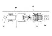
図1〜図3は、本発明の収穫作業機に相当する集草機を示す。トラクター1に牽引される集草機は、PTO軸からの動力でローター4を駆動し、タイン3の回転により刈草を中央に集め、コンパクトな集草列11を作成する。(First embodiment)
1 to 3 show a grass collecting machine corresponding to the harvesting machine of the present invention. The grass-tractor towed by the
また、最後尾には、集草機の進行軌跡を表すマーク20を、集草後の圃場の地表面に付すためのマーキング装置5が搭載されている。 Further, a marking
図2にあるように、集草前の刈草10を集草機が進行しながら集草列11が形成され、マーキング装置5により集草機の進行軌跡を表すマーク20が圃場の表面に付される。この時、マーク20は、図3に示すように圃場に付されることになる。すなわち、集草列11は集草機の進行軌跡と完全に並行になるから、マーク20をロールベーラ50(収穫物処理作業機)が追えば、確実に集草列11に沿ってロールベーラ50を走行させることが可能となる。仮に、障害物が圃場にあり、そこを避けて集草機が進んだとしても、集草機の進行軌跡を表すマーク20は、曲がっていようが集草列11に沿って並行に圃場に描かれる。ロールベーラ50はマーク20をマーク検出器40により検出し走行するから、ロールベーラ50が集草列11にアクセスするのに何の支障もない。 As shown in FIG. 2, a
圃場の端部で集草機(収穫作業機)が旋回するときには、マーク20が付されないように構成できるし、また、旋回しているときにもマーク20が付されるようにも構成できる。 When the grass collector (harvesting machine) turns at the end of the field, the
マーク20は、図5にあるように、収穫物処理作業機に相当するロールベーラ50に設けられたマーク検出器40により検出できるものであれば、如何なるものでもよく電磁波反射材や電磁波発信機等であってもかまわない。圃場にマーク20が付されることから、無害なものが好ましい。例えば、土壌と区別できる色の着色物質でよい。土壌改良剤である石灰(白色)そのものも使用可能であるが、さらに石灰に着色物質を加えたものでもよい。加えて、生分解性樹脂でできた棒(ペグ)などでもよく、収穫物処理作業機が有するマーク検出器40により収穫作業機の進行軌跡が検出できるものであれば材質や構造を問わない。 As shown in FIG. 5, any mark may be used as the
また、マーク20は連続して圃場に付される、すなわち、線状に付されると検出が楽にできて好ましいが、必ずしも連続して圃場に付される必要はなく、進行軌跡を再構成できればマーク20の使用量を節約するために離散的に付されてもよい。 Further, it is preferable that the
収穫物処理作業機であるロールベーラ50は、マーク20を検出しながら進めばよく、無人化も可能である。無人化しなくとも、搭乗者の操向作業をアシストでき、作業負担を軽減できる。 The
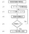
集草機(収穫作業機)が往復する際に示されるマーク20を往路で1本とカウントし、復路で1本とカウントしこれを作業開始時から連続してカウントした数を、記憶するまたは送信する。カウントはどのようにも行えるが、図6はその一例である。s1で収穫機作業開始がなされると、s2で作業者はマーキング装置5のスイッチを入れマーキング装置5を始動させる。すると、圃場にマーク20が付され、s3でマーク本数がカウントされる。初期値のnは0に設定されているから、s3においてマーク本数は1本とカウントされる。s4で収穫作業機の旋回が検出されると、作業終了か否かの判断がs5でなされ、作業終了でない(No)であれば、s3に戻りマーク本数のカウントが継続する。s5で作業の終了が判断されるとマーク総本数nが送信される。
また、収穫作業機の作業が終了した後、時間をおいて収穫物処理作業機の作業が始まる等の場合にあっては、s6の前記マーク総本数を一旦収穫作業機に記憶させておき、後でマーク列特定装置を有する収穫物処理作業機へ送信することも可能であるし、収穫作業機に記憶されたマーク総本数を呼び出し表示させ、収穫物処理作業機の搭乗者がマーク総本数を収穫物処理作業機の操作パネルからマーク列特定装置へ入力することも可能である。The
Further, in the case where the work of the harvest processing machine is started after a while after the work of the harvesting machine is finished, the total number of marks in s6 is temporarily stored in the harvesting machine, It is also possible to send it later to the harvest processing machine that has a mark row specifying device, and the total number of marks stored in the harvesting machine is called up and displayed so that the passenger of the harvest processing machine can display the total number of marks. Can be input to the mark row specifying device from the operation panel of the harvest processing work machine.
ロールベーラ50(収穫物処理作業機)が収穫作業機の作業終了を待たずに作業を開始する場合は、s4とs5の間に、マーク本数nをロールベーラ50(収穫物処理作業機)に送信するようにしてもよい。 When the roll baler 50 (harvest processing machine) starts the work without waiting for the end of the harvesting machine, the number of marks n is transmitted to the roll baler 50 (harvest processing machine) between s4 and s5. You may do it.
集草機(収穫作業機)またはロールベーラ50(収穫物処理作業機)は、s6で送られたマーク総本数nに基づき、圃場の地表面に付された多数のマーク列93毎に番号などの識別子94(マーク列情報)を付すこともできる。(図10参照) The grass collecting machine (harvesting work machine) or the roll baler 50 (harvest processing work machine), based on the total number n of marks sent in s6, assigns a number or the like to each of the large number of
収穫作業機がマークする際、往路および復路で分けたすべてのマーク列に番号等の識別子94(マーク列情報)を付与すれば、図10に示すように、該マーク列93につけられた番号等の識別子94により、多数あるマーク列からどの位置にあるマーク列93かを特定できるようになる。 When the harvesting machine marks, if an identifier 94 (mark row information) such as a number is given to all the mark rows divided in the forward and return paths, as shown in FIG. 10, the numbers assigned to the
多数あるマーク列のどのマーク列93かを特定できる画像処理装置などのマーク列特定装置を設け、マーク列93の番号を認識できるように構成すれば、収穫物処理作業機は、現在どの番号のマーク列93に沿って作業しているのか認識できる。作業開始時に、マーク列特定装置が認識しているマーク列93の番号を、作業者が教えさえすれば、当該マーク列を基準に、後は自動的にどの番号のマーク列93かをマーク列特定装置が自動的に判断する。収穫物処理作業機は、マーク列93の番号を認識し、各々のマーク列93の始点または終点からマークに沿って走行するように自動操縦される。 If a mark row specifying device such as an image processing apparatus that can specify which
複数台のロールベーラ50(収穫物処理作業機)を同時に使用する場合、奇数番号のマーク列93と偶数番号のマーク列93というように予め割り振りをしておけば、ロールベーラ50を無人化しても複雑な制御装置を必要とすることなく、複数台のロールベーラ50で分担して作業できる。
集草機(収穫作業機)は通例、略等間隔に収穫作業を行うから、その進行軌跡を表すマーク20もまた等間隔に圃場に付されることになる。マーク列93の総本数がわかれば、別途取得した現場の圃場地図とマーク列93を重ね合わせて表示させることもできる。When using multiple roll balers 50 (harvest processing machines) at the same time, it is complicated even if the
Since the grass collecting machine (harvesting machine) usually performs harvesting work at substantially equal intervals, the
図10は、実際に圃場地図とマーク列93を重ね合わせたものを示している。 FIG. 10 shows an actual field map and
集草列11は、通例中央が盛り上がっているから、ロールベーラ50をマークに沿って直進させるとロールベール51の中央に刈草が集まり中央が盛り上がった紡錘形のロールベール51となる。そこで、マーク20を検出しながら左右にわずかに蛇行するようにロールベーラ50を進行させると、きれいなロールベール51が形成される。 Since the center of the
(第2の実施態様)
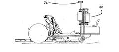
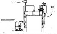
図4および図5に示すように、収穫作業機をロールベーラ50とすることもできる。この場合、ラッピングマシン80が収穫物処理作業機となる。ロールベーラ50の進行軌跡上またはその付近には、必ずロールベール51が存在し、図9A〜図9C記載のラッピングマシン80は、マーク検出器40(図示せず)より、地表面に付されたマークを認識して操向制御され、ロールベーラ50が圃場に付したマーク20を頼りに、ロールベール51を発見できる。
ラッピングマシン80を無人化する場合は、マーク列特定装置に加え、ロールベール51を認識できる画像認識装置などの収穫物位置認識装置をラッピングマシン80に備えれば簡単に無人化できる。ロールベール51は大きく、圃場には他に紛らわしい物体は存在しないので、収穫物位置認識装置により簡単に収穫物の位置を認識できる。
また、第2の実施態様では、支柱上にマーク列特定装置兼収穫物位置認識装置71が設けられており、1つの装置71で、どの番号のマーク列を作業しているのか(図10参照)収穫物処理作業機は認識しつつ、収穫物位置の認識も行われる。
さらに、コストダウンのため、マーク列特定装置、マーク検出器および収穫物位置認識装置をすべて1つの画像認識装置等で兼用することが可能である。(Second embodiment)
As shown in FIGS. 4 and 5, the harvesting machine may be a
When the wrapping
Further, in the second embodiment, the mark row identifying device/harvested object
Further, in order to reduce the cost, it is possible to combine the mark row specifying device, the mark detector and the harvested position recognizing device into one image recognizing device or the like.
ロールベーラ50は、図10の1番目のマーク列93にはロールベール51が2個、2番目のマーク列93にはロールベール51が0個等のように、マーク列93毎のロールベール51の個数情報をラッピングマシン80(収穫物処理作業機)に送信してもよい。マーク検出器40によりマーク列93に沿って走行するラッピングマシン80が、当該マーク列93上のすべてのロールベール51を処理したかを、ロールベーラ50から送信されたロールベール51の個数情報によって判断すれば、マーク列93の終点まで走行することなく、隣のマーク列93へ作業を移れる。 The
複数台のラッピングマシン80を使用する場合には、上記第1の実施態様のように、偶数番号または奇数番号のマーク列93のように、予め割り振りすることもできるし、前記マーク列93毎のロールベール51の数を考慮して、複数台のラッピングマシン80に均等な数になるようにマーク列93を割り振ることもできる。 When a plurality of
(第1および第2の実施態様の変形例)
集草機(収穫作業機)が圃場に付したマークを検出し操向制御する収穫物処理作業機は、ロールベーラ50とラッピングマシン80であってもよい。この場合、ラッピングマシン80とロールベーラ50は、略同じ進行軌跡をたどるため、集草機が付したマーク20を利用して、ロールベーラ50とラッピングマシン80が共に操向制御される。(Modifications of the first and second embodiments)
The
(第3の実施態様)
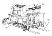
図7および図8は、根菜類用ハーベスタ60(収穫作業機)の例である。図7に記載されているように、収穫された根菜類は、コンベヤ62を介して昇降荷台61に載せた収穫物コンテナ(図示せず)に投入される。満杯になると、図8のように昇降荷台61を下ろし、根菜類用ハーベスタ60の機台を前後させて、圃場に収穫物コンテナ(図示せず)を放置する。マーキング装置5は図示していないが、適宜な位置にマーキング装置5が設けられており、圃場の地表面にその進行軌跡を表すマーク20を付せば、満杯となった収穫物コンテナを回収する作業機(収穫物処理作業機)がマーク20を検出しながら操向制御されて、回収作業を行う。また、収穫物はコンテナに代えて、収穫物収納袋に入れられて、圃場に放置されるものであってもよい。
根菜用ハーベスタ60に限らず、穀類用、果菜類用または葉菜類用ハーベスタであってもかまわない。(Third embodiment)
7 and 8 are examples of a root vegetable harvester 60 (harvesting machine). As shown in FIG. 7, the harvested root vegetables are put into a harvest container (not shown) mounted on the
The harvester is not limited to the
(マークの機能)
収穫物処理作業機が有人で操縦されている場合、集草列11を搭乗者が見つける。そして、集草列に沿って圃場に付されたマーク20をマーク検出器40で検出して自動操向制御するので搭乗者の負担を軽減できる。このような作業形態を採るときには、何番目のマーク列93に沿って、作業が行われているか収穫物処理作業機が知る必要はない。(Mark function)
If the crop handling implement is manned, the occupants will find the
ところが、収穫物処理作業機を無人制御したい場合は、何番目のマーク列93を走行しているか収穫物処理作業機が認識する必要がある。収穫作業機が圃場を往復する際に、進行軌跡を表すマーク20を往路、復路で分けて本数を作業開始時からカウントし、該カウントを記憶する装置および/または送信する装置を設けることで、多数のマーク列93の位置関係を決めることができる。収穫物処理作業機にマーク列93を認識できる画像認識装置等のマーク列特定装置を付ければ、どの位置のマーク列93を作業しているのか無人の収穫物処理作業機が判断して走行させることができる。 However, when it is desired to perform unmanned control of the harvest processing implement, it is necessary for the harvest processing implement to recognize which
必ずしも、地図とマーク列93を重ね合わせる必要はないが、図10のように、圃場の作業領域を示す地図とマーク列93を重ね合わせるときには、未収穫領域91を除いた収穫済み領域90に対してマーク列93は等間隔でかつ直線であると仮定して、マーク列93の本数分だけ等間隔に直線のマーク列93が描くようにすることもできる。 It is not always necessary to superimpose the map and the
地図に、圃場の地表面に付された多数のマーク列93に番号等のマーク識別子94(マーク列情報)を付すことで、おおまかな位置の把握が容易になる。 By attaching a mark identifier 94 (mark sequence information) such as a number to a large number of
マーク検出器40は単純で安価な装置で足り、収穫物は、必ず収穫作業機の進行軌跡上またはその近傍に存在するため、収穫物処理作業機が、マーク20をたどれば必ず収穫物にアクセスできることになる。 The
また、収穫物は前記したように収穫作業機の進行軌跡上にまたはその近傍に存在するので、圃場に高低差がある等の事情により曲線を描いて進むことがあったとしても、問題なく使用できる。 In addition, since the harvested product exists on or near the path of travel of the harvesting machine as described above, it can be used without problems even if it may proceed in a curved line due to height differences in the field. it can.
さらに、収穫物処理作業機が収穫物を運ぶため一旦作業を中断し移動したとしても、作業中断時のマーク列93の番号を収穫物処理作業機が記憶しておけば、確実に作業中断時のマーク列93に復帰でき、作業を確実に再開できる。 Further, even if the harvesting processing machine carries out harvesting and carries out the harvesting, even if the operation is once interrupted and moved, if the harvesting processing machine remembers the number of the
(収穫物処理作業機に設けられた検出器および他の装置)
収穫物処理作業機に設けられた検出器は、マーク20に沿って収穫物処理作業機を操向制御するための地表面に付されたマーク20を検出するマーク検出器40であるが、前記したように次の装置を加えることもできる。
(1)ロールベール51、コンテナ、収穫物収納袋等を認識し処理し、それらに収穫物処理作業機がアクセスするのに使用される収穫物位置認識装置
(2)マーク列93の番号等の識別子94を特定するために使用されるマーク列特定装置(Detectors and other devices provided in harvest processing machines)
The detector provided in the harvest processing work machine is the
(1) A crop position recognizing device used for recognizing and processing the
マーク検出器40は、操向制御をするために地表面のマーク20を検出するから、正確な検出を行うために比較的地表面に近いところに設けてもよい。しかし、地表面に近いと正確な検出が期待できるものの、どうしても検出範囲が狭くなるため地表面から離れたところに設けることで、マーク20を見失うことを防ぐこともできる。 Since the
マーク検出器40、マーク列特定装置および収穫物位置認識装置は、別体の装置として設けることもできるが、1つの装置で兼用することも可能である。マーク列特定装置および収穫物位置認識装置を1つの装置で兼用した例が、図9A〜図9Cに記載のマーク列特定装置兼収穫物位置認識装置71である。 The
マーク列特定装置は、多数のマーク列93を認識するために収穫物処理作業機の高い位置に設けることが好ましい。また、マーク列特定装置をドローンに設けて、その情報を収穫物処理作業機が受信できるようにしてもよい。 The mark row identifying device is preferably provided at a high position of the harvest processing machine in order to recognize a large number of
収穫物位置認識装置は、収穫物処理作業機の前方に向けて設けられ、認識するロールベール51、コンテナ、収穫物収納袋等の収穫物の大きさにより、設ける位置は適宜決められる。 The harvested product position recognition device is provided toward the front of the harvested product processing machine, and the installation position is appropriately determined depending on the size of the harvested product such as the
マーク検出器40がマーク20を見失った場合、マーク列特定装置により、マーク検出器40のマーク検出復帰をアシストするように制御することが好ましい。 When the
(地図)
地図は、地図の作製は収穫作業機または収穫物処理作業機が行ってもよいし、収穫作業機のデータをネットワークに接続し、ネットワーク上でまたはネットワークに接続した別途の装置で地図を作成し、収穫物処理作業機へ送っても構わない。(map)
The map may be created by the harvesting machine or the harvest processing machine, or by connecting the data of the harvesting machine to the network and creating the map on the network or by a separate device connected to the network. It may be sent to a harvest processing machine.
1 トラクター
3 タイン
4 ローター
5 マーキング装置
10 集草前の刈草
11 集草列
20 進行軌跡を表すマーク
40 マーク検出器
50 ロールベーラ
51 ロールベール
60 根菜類用ハーベスタ
61 昇降荷台
62 コンベヤ
71 マーク列特定装置兼収穫物位置認識装置
80 ラッピングマシン
90 収穫済み領域
91 未収穫領域
93 マーク列
94 マーク列識別子(番号)1
Claims (9)
Translated fromJapanese圃場の作業領域に前記マーク列が等間隔に付されていると仮定し、前記カウント数から推定される前記マーク列の推定位置求め、地図上の作業領域に前記マーク列を重ね合わせる装置へと、前記カウント数を送る装置を設けた収穫物処理作業機。In the harvesting machine according to claim 8,
Assuming that the mark rows are provided at equal intervals in the work area of the field, the estimated position of the mark row estimated from the count number is obtained, and the mark row is superposed on the work area on the map. A harvest processing machine provided with a device for sending the count number.
Priority Applications (1)
| Application Number | Priority Date | Filing Date | Title |
|---|---|---|---|
| JP2018235607AJP7282512B2 (en) | 2018-12-17 | 2018-12-17 | harvest machine |
Applications Claiming Priority (1)
| Application Number | Priority Date | Filing Date | Title |
|---|---|---|---|
| JP2018235607AJP7282512B2 (en) | 2018-12-17 | 2018-12-17 | harvest machine |
Publications (2)
| Publication Number | Publication Date |
|---|---|
| JP2020096543Atrue JP2020096543A (en) | 2020-06-25 |
| JP7282512B2 JP7282512B2 (en) | 2023-05-29 |
Family
ID=71105549
Family Applications (1)
| Application Number | Title | Priority Date | Filing Date |
|---|---|---|---|
| JP2018235607AActiveJP7282512B2 (en) | 2018-12-17 | 2018-12-17 | harvest machine |
Country Status (1)
| Country | Link |
|---|---|
| JP (1) | JP7282512B2 (en) |
Cited By (4)
| Publication number | Priority date | Publication date | Assignee | Title |
|---|---|---|---|---|
| JP2020174587A (en)* | 2019-04-18 | 2020-10-29 | 株式会社Ihiアグリテック | Harvest operating machine and harvest processing work machine |
| JP2021105794A (en)* | 2019-12-26 | 2021-07-26 | 井関農機株式会社 | Control system of working vehicle |
| EP4268569A1 (en) | 2022-04-28 | 2023-11-01 | Kubota Corporation | Working machine and working device |
| CN119148712A (en)* | 2024-09-12 | 2024-12-17 | 深圳库犸科技有限公司 | Control method for discharging grass and related device |
Citations (11)
| Publication number | Priority date | Publication date | Assignee | Title |
|---|---|---|---|---|
| US3395771A (en)* | 1965-05-21 | 1968-08-06 | Int Harvester Co | Tractor guidance system |
| JPS5113390Y2 (en)* | 1974-04-26 | 1976-04-10 | ||
| JPS5645105A (en)* | 1979-09-18 | 1981-04-24 | Iseki Agricult Mach | Farm tractor with direction controller |
| US4345659A (en)* | 1980-07-10 | 1982-08-24 | Browwer Turf Equipment Limited | Automatic steering mechanism for sod processing machine and shoe therefor |
| JPS645413A (en)* | 1987-06-30 | 1989-01-10 | Mitsubishi Agricult Mach | Automatic steering device of agricultural working machine |
| JPH05197421A (en)* | 1992-01-22 | 1993-08-06 | Yanmar Agricult Equip Co Ltd | Self-propelled work machine guidance wire burying device |
| JPH0641406U (en)* | 1992-11-12 | 1994-06-03 | ヤンマー農機株式会社 | Marker device for induction cable of mobile agricultural machinery |
| JPH07222508A (en)* | 1994-02-10 | 1995-08-22 | Fuji Heavy Ind Ltd | Self-traveling working vehicle |
| JP2014186723A (en)* | 2013-02-19 | 2014-10-02 | Muroran Institute Of Technology | Automatic plant harvesting machine, automatic plant harvesting program, and automatic plant harvesting method |
| JP2017012134A (en)* | 2015-07-06 | 2017-01-19 | ヤンマー株式会社 | Work vehicle cooperation system |
| JP2018099042A (en)* | 2016-12-19 | 2018-06-28 | 株式会社クボタ | Work vehicle automatic traveling system |
- 2018
- 2018-12-17JPJP2018235607Apatent/JP7282512B2/enactiveActive
Patent Citations (11)
| Publication number | Priority date | Publication date | Assignee | Title |
|---|---|---|---|---|
| US3395771A (en)* | 1965-05-21 | 1968-08-06 | Int Harvester Co | Tractor guidance system |
| JPS5113390Y2 (en)* | 1974-04-26 | 1976-04-10 | ||
| JPS5645105A (en)* | 1979-09-18 | 1981-04-24 | Iseki Agricult Mach | Farm tractor with direction controller |
| US4345659A (en)* | 1980-07-10 | 1982-08-24 | Browwer Turf Equipment Limited | Automatic steering mechanism for sod processing machine and shoe therefor |
| JPS645413A (en)* | 1987-06-30 | 1989-01-10 | Mitsubishi Agricult Mach | Automatic steering device of agricultural working machine |
| JPH05197421A (en)* | 1992-01-22 | 1993-08-06 | Yanmar Agricult Equip Co Ltd | Self-propelled work machine guidance wire burying device |
| JPH0641406U (en)* | 1992-11-12 | 1994-06-03 | ヤンマー農機株式会社 | Marker device for induction cable of mobile agricultural machinery |
| JPH07222508A (en)* | 1994-02-10 | 1995-08-22 | Fuji Heavy Ind Ltd | Self-traveling working vehicle |
| JP2014186723A (en)* | 2013-02-19 | 2014-10-02 | Muroran Institute Of Technology | Automatic plant harvesting machine, automatic plant harvesting program, and automatic plant harvesting method |
| JP2017012134A (en)* | 2015-07-06 | 2017-01-19 | ヤンマー株式会社 | Work vehicle cooperation system |
| JP2018099042A (en)* | 2016-12-19 | 2018-06-28 | 株式会社クボタ | Work vehicle automatic traveling system |
Cited By (5)
| Publication number | Priority date | Publication date | Assignee | Title |
|---|---|---|---|---|
| JP2020174587A (en)* | 2019-04-18 | 2020-10-29 | 株式会社Ihiアグリテック | Harvest operating machine and harvest processing work machine |
| JP7241593B2 (en) | 2019-04-18 | 2023-03-17 | 株式会社Ihiアグリテック | Harvesting and processing machines |
| JP2021105794A (en)* | 2019-12-26 | 2021-07-26 | 井関農機株式会社 | Control system of working vehicle |
| EP4268569A1 (en) | 2022-04-28 | 2023-11-01 | Kubota Corporation | Working machine and working device |
| CN119148712A (en)* | 2024-09-12 | 2024-12-17 | 深圳库犸科技有限公司 | Control method for discharging grass and related device |
Also Published As
| Publication number | Publication date |
|---|---|
| JP7282512B2 (en) | 2023-05-29 |
Similar Documents
| Publication | Publication Date | Title |
|---|---|---|
| JP2020096543A (en) | Harvesting work machine | |
| US9326443B2 (en) | Arrangement and method for the automatic transfer of crops from a harvesting machine to a transport vehicle | |
| JP2019028688A (en) | Harvesting system for autonomously-traveling combine harvester | |
| JP7381402B2 (en) | automatic driving system | |
| EP3314997B1 (en) | A crop management system for processing crop material | |
| JP2018201342A (en) | Agricultural work support system | |
| EP3314996B1 (en) | A crop management system for processing crop material | |
| US11793111B2 (en) | Harvesting head reel-mounted laser measurement | |
| DE102021107465B4 (en) | CONTROL DEVICE AND WORKING MACHINE | |
| JP2019110782A (en) | Travel route calculation system | |
| JP7241593B2 (en) | Harvesting and processing machines | |
| CA2997581C (en) | Methods for creating merged triple windrows | |
| JP7231397B2 (en) | Harvest Access System and Harvest Access Method | |
| JP2024071518A (en) | Crop Harvesting Vehicle | |
| KR20200085276A (en) | Harvester, limit mileage calculation program, recording medium recording limit mileage calculation program, limit mileage calculation method, farm work vehicle, turning control program, recording medium recording turning control program, turning control method, combine control system, combine control Program, recording medium recording a combine control program, and combine control method | |
| JP7231396B2 (en) | Harvest processing machine | |
| JP7466276B2 (en) | Work vehicle coordination system | |
| WO2014105927A1 (en) | Using a virtual boom to steer agricultural equipment along the edge of worked/unworked areas | |
| JP6919678B2 (en) | Work route creation system and combine | |
| KR20230115975A (en) | Agricultural machine, agricultural machine control program, recording medium recording agricultural machine control program, agricultural machine control method | |
| JPH0617411U (en) | Automatic combine paddy discharge control device | |
| JP7738540B2 (en) | System and work vehicle | |
| US20250098581A1 (en) | Agricultural Implement Monitoring | |
| US20240000010A1 (en) | Combine Automation Regime-based Control | |
| KR20230001512A (en) | Work support system |
Legal Events
| Date | Code | Title | Description |
|---|---|---|---|
| A621 | Written request for application examination | Free format text:JAPANESE INTERMEDIATE CODE: A621 Effective date:20211011 | |
| A977 | Report on retrieval | Free format text:JAPANESE INTERMEDIATE CODE: A971007 Effective date:20220620 | |
| A131 | Notification of reasons for refusal | Free format text:JAPANESE INTERMEDIATE CODE: A131 Effective date:20220802 | |
| A521 | Request for written amendment filed | Free format text:JAPANESE INTERMEDIATE CODE: A523 Effective date:20220909 | |
| A131 | Notification of reasons for refusal | Free format text:JAPANESE INTERMEDIATE CODE: A131 Effective date:20221227 | |
| A521 | Request for written amendment filed | Free format text:JAPANESE INTERMEDIATE CODE: A523 Effective date:20230116 | |
| TRDD | Decision of grant or rejection written | ||
| A01 | Written decision to grant a patent or to grant a registration (utility model) | Free format text:JAPANESE INTERMEDIATE CODE: A01 Effective date:20230509 | |
| A61 | First payment of annual fees (during grant procedure) | Free format text:JAPANESE INTERMEDIATE CODE: A61 Effective date:20230517 | |
| R150 | Certificate of patent or registration of utility model | Ref document number:7282512 Country of ref document:JP Free format text:JAPANESE INTERMEDIATE CODE: R150 |