JP2020093600A - Reflected light detection device, reflected light detection method and program - Google Patents
Reflected light detection device, reflected light detection method and programDownload PDFInfo
- Publication number
- JP2020093600A JP2020093600AJP2018231300AJP2018231300AJP2020093600AJP 2020093600 AJP2020093600 AJP 2020093600AJP 2018231300 AJP2018231300 AJP 2018231300AJP 2018231300 AJP2018231300 AJP 2018231300AJP 2020093600 AJP2020093600 AJP 2020093600A
- Authority
- JP
- Japan
- Prior art keywords
- visible light
- vehicle
- reference value
- light image
- image
- Prior art date
- Legal status (The legal status is an assumption and is not a legal conclusion. Google has not performed a legal analysis and makes no representation as to the accuracy of the status listed.)
- Granted
Links
Images


Landscapes
- Investigating Or Analysing Materials By Optical Means (AREA)
- Lighting Device Outwards From Vehicle And Optical Signal (AREA)
Abstract
Description
Translated fromJapanese本発明は、反射光検出装置、反射光検出方法およびプログラムに関する。 The present invention relates to a reflected light detection device, a reflected light detection method and a program.
自車両の前方に位置する対向車を検出し、対向車に向けてハイビームが照らされないように車両の前照灯の配光を自動的に制御する技術が知られている。また、人や動物等の熱源を赤外線カメラで検知し、人や動物等にもハイビームが照らされないように前照灯の配光を制御する技術が提案されている(例えば、特許文献1参照)。 There is known a technique of detecting an oncoming vehicle located in front of the own vehicle and automatically controlling light distribution of a headlight of the vehicle so that the high beam is not illuminated toward the oncoming vehicle. Further, a technology has been proposed in which a heat source of a person or an animal is detected by an infrared camera, and the light distribution of a headlight is controlled so that the high beam is not illuminated on the person or the animal (for example, see Patent Document 1). ..
本発明者は、自車両の照灯の反射光によって自車両の運転者が感じる眩しさに着目し、自車両の運転者が感じる眩しさを軽減できればより好ましいと考えた。 The present inventor paid attention to the glare felt by the driver of the own vehicle by the reflected light of the lighting of the own vehicle, and thought that it would be more preferable if the glare felt by the driver of the own vehicle could be reduced.
本発明は、上述の事情に鑑みてなされたものであり、自車両の照灯の反射光を適切に検出する技術を提供することを目的とする。 The present invention has been made in view of the above circumstances, and an object of the present invention is to provide a technique for appropriately detecting reflected light from a lamp of a vehicle.
本発明のある態様の反射光検出装置は、自車両の照灯により照らされる車外を可視光で撮像した可視光画像と、可視光画像の撮像範囲からの赤外線を撮像した赤外線画像と、可視光画像の撮像範囲に含まれる対象物までの距離を測定した距離情報とを取得する取得部と、可視光画像における輝度が第1基準値以上であり、赤外線画像における輝度が第2基準値以下であり、距離が第3基準値以下である条件を満たす可視光画像の撮像範囲に含まれる特定領域を特定する特定部と、特定部により特定領域が特定される場合に所定の信号を出力する出力部と、を備える。 A reflected light detection device according to an aspect of the present invention is a visible light image obtained by visualizing the outside of a vehicle illuminated by a light of the vehicle with visible light, an infrared image obtained by taking infrared rays from an imaging range of the visible light image, and a visible light. An acquisition unit that acquires distance information obtained by measuring a distance to an object included in the imaging range of the image, brightness in the visible light image is equal to or higher than the first reference value, and brightness in the infrared image is equal to or lower than the second reference value. And an output that outputs a predetermined signal when the specific region is specified by the specifying unit, which specifies the specific region included in the imaging range of the visible light image satisfying the condition that the distance is equal to or less than the third reference value And a section.
本発明の別の態様は、反射光検出方法である。この方法は、自車両の照灯により照らされる車外を可視光で撮像した可視光画像と、可視光画像の撮像範囲からの赤外線を撮像した赤外線画像と、可視光画像の撮像範囲に含まれる対象物までの距離を測定した距離情報とを取得するステップと、可視光画像における輝度が第1基準値以上であり、赤外線画像における輝度が第2基準値以下であり、距離が第3基準値以下である条件を満たす可視光画像の撮像範囲に含まれる特定領域を特定するステップと、特定領域が特定される場合に所定の信号を出力するステップと、を備える。 Another aspect of the present invention is a reflected light detection method. This method is a visible light image of the outside of the vehicle illuminated by the light of the vehicle with visible light, an infrared image of infrared rays from the visible light image capturing range, and an object included in the visible light image capturing range. A step of acquiring distance information obtained by measuring the distance to the object, the brightness in the visible light image is equal to or higher than the first reference value, the brightness in the infrared image is equal to or lower than the second reference value, and the distance is equal to or lower than the third reference value. And a step of outputting a predetermined signal when the specific area is specified, and a step of specifying the specific area included in the imaging range of the visible light image satisfying a certain condition.
なお、以上の構成要素の任意の組合せや本発明の構成要素や表現を、方法、装置、システムなどの間で相互に置換したものもまた、本発明の態様として有効である。 It should be noted that any combination of the above constituent elements and constituent elements and expressions of the present invention that are mutually replaced among methods, devices, systems, etc. are also effective as an aspect of the present invention.
本発明によれば、自車両の照灯の反射光を適切に検出できる。 According to the present invention, it is possible to appropriately detect the reflected light of the lamp of the host vehicle.
以下、本発明の実施の形態について、図面を参照しつつ説明する。かかる実施の形態に示す具体的な数値等は、発明の理解を容易とするための例示にすぎず、特に断る場合を除き、本発明を限定するものではない。なお、本明細書及び図面において、実質的に同一の機能、構成を有する要素については、同一の符号を付することにより重複説明を省略し、また本発明に直接関係のない要素は図示を省略する。 Embodiments of the present invention will be described below with reference to the drawings. Specific numerical values and the like shown in the embodiments are merely examples for facilitating the understanding of the invention, and do not limit the present invention unless otherwise specified. In this specification and the drawings, elements having substantially the same function and configuration are denoted by the same reference numerals to omit redundant description, and elements not directly related to the present invention are omitted. To do.
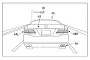
図1は、自車両50の前照灯32の照明光52が前方の物体により反射される様子を模式的に示す図である。図1では、信号待ちなどのために停車している前方車両60に接近して自車両50が停車している状態を示している。前照灯32からの照明光52は、主に前方車両60の後部に入射し、そのうちの特定箇所62(反射箇所ともいう)にて強く反射されている。特定箇所62からの反射光54が運転者56の目に向かうと、運転者56は眩しさを感じる。このような状況下において、前照灯32を一時的に消灯したり、前照灯32の光量を一時的に低減したり、照明光52が反射箇所62に入射しないように前照灯32の配光パターンを変更したりすれば、運転者56が感じる眩しさを軽減できると考えられる。 FIG. 1 is a diagram schematically showing how the
本実施の形態では、自車両50の照灯の反射光54が眩しい状況を適切に検知することで、運転者56が感じる眩しさを低減しうる技術を提供する。具体的には、自車両50に設けられる可視光カメラ22および赤外線カメラ24が撮像する画像と、自車両50に設けられる距離センサ26が測定する距離情報とに基づいて、反射光54が眩しい状況を検知する。 The present embodiment provides a technique capable of reducing the glare felt by the
図2は、反射光検出装置10の機能構成を模式的に示すブロック図である。図示する各機能ブロックは、ハードウェア的には、コンピュータのCPUやメモリをはじめとする素子や機械装置で実現でき、ソフトウェア的にはコンピュータプログラム等によって実現されるが、ここでは、それらの連携によって実現される機能ブロックとして描いている。したがって、これらの機能ブロックはハードウェア、ソフトウェアの組み合わせによっていろいろなかたちで実現できることは、当業者には理解されるところである。 FIG. 2 is a block diagram schematically showing the functional configuration of the reflected
反射光検出装置10は、車載ネットワーク40を介して自車両50に搭載される各種機器と接続される。車載ネットワーク40には、可視光カメラ22、赤外線カメラ24、距離センサ26、車載センサ28、照灯制御装置30などが接続される。車載ネットワーク40は、例えばCAN(Controller Area Network)やイーサネット(登録商標)により構成される。反射光検出装置10の機能構成を詳述する前に周辺機器について説明する。 The reflected
可視光カメラ22は、自車両50の周辺を撮像するよう構成され、例えば、前照灯32の照明光52により照らされる車外を可視光で撮像する。可視光カメラ22の設置位置は問わないが、例えば車内のリアビューミラーの近傍に可視光カメラ22を取り付けることができる。可視光カメラ22は、いわゆるドライブレコーダ用のカメラであってもよい。可視光カメラ22は、車両の室外のみを撮像するように構成されてもよいし、車両の室外および室内の双方を撮像するように構成されてもよい。 The
赤外線カメラ24は、自車両50の周辺からの赤外線を撮像するよう構成され、可視光カメラ22の撮像範囲の少なくとも一部からの赤外線を撮像するよう配置される。赤外線カメラ24は、いわゆる赤外線サーモグラフィであり、自車両50の周辺の温度分布を画像化し、自車両50の周辺に存在する熱源を特定できるようにする。赤外線カメラ24は、波長2μm〜5μm程度の中赤外線を検出するよう構成されてもよいし、波長8μm〜14μm程度の遠赤外線を検出するよう構成されてもよい。赤外線カメラ24の設置位置は問わないが、例えば自車両50のフロントバンパー付近に取り付けることができる。赤外線カメラ24は、熱源からの赤外線を精度良く検出できるように車外に設けられることが望ましい。 The
距離センサ26は、自車両50の周辺に存在する対象物までの距離を測定する。距離センサ26の一例としては、超音波センサやレーダセンサであり、可視光カメラ22の撮像範囲に含まれる対象物までの距離を測定するよう構成される。距離センサ26の別の例は、ライダ(LiDAR;Light Detection and Ranging)であり、可視光カメラ22の撮像範囲の少なくとも一部の距離画像を取得するよう構成される。距離センサ26の設置位置は問わないが、例えば自車両50のフロントバンパー付近や車内のリアビューミラーの近傍に取り付けることができる。距離センサ26は、可視光カメラ22に近傍に設けられてもよく、可視光カメラ22と一体化されたセンサモジュールを構成してもよい。 The
車載センサ28は、車両に関する情報や車両の周辺状況に関する情報を取得するための機器である。車載センサ28には、外気温センサ、車速センサ、舵角センサ、加速度センサ、ジャイロセンサ、位置情報センサ(GPSセンサ)などが挙げられるが、これらに限定されるものではない。 The vehicle-mounted
照灯制御装置30は、自車両50の前照灯32の動作を制御する。照灯制御装置30は、例えば、前照灯32のオンオフや、前照灯32の上向き点灯(ハイビーム)および下向き点灯(ロービーム)の切替などをする。照灯制御装置30は、前照灯32の照射範囲、照射照度および照射方向の少なくとも一つを制御できるように構成されてもよい。照灯制御装置30は、例えば、前照灯32が照射可能な照射範囲の一部のみに照明光52が照らされるようにしたり、照明光52の照射方向を上下左右に移動させたり、照明光52の照度を段階的に変化させたりしてもよい。 The
つづいて、反射光検出装置10の機能構成を詳述する。反射光検出装置10は、取得部12、特定部14、抽出部16、出力部18を備える。 Subsequently, the functional configuration of the reflected
取得部12は、自車両50の周辺状況に関する情報を取得する。取得部12は、可視光カメラ22により撮像された可視光画像と、赤外線カメラ24により撮像された赤外線画像と、距離センサ26により測定された距離情報とを取得する。 The
図3は、可視光画像を模式的に示す図であり、図1に示す状況下で自車両50の前方を撮像した可視光画像を示す。図示されるように、可視光画像には前方車両60の後部や信号機70が含まれるとともに、運転者56が眩しさを感じる反射箇所62やブレーキランプ64L,64Rが含まれている。可視光画像では、ランプが点灯しているブレーキランプ64L,64Rや信号機70、自車両50の前照灯32の照明光52が強く反射している反射箇所62などが明るく写し出される。 FIG. 3 is a diagram schematically showing a visible light image, and shows a visible light image obtained by imaging the front of the
図4は、赤外線画像を模式的に示す図であり、図1に示す状況下で自車両50の前方を撮像した赤外線画像を示す。赤外線画像では、主に熱源となる温度の高い部分が明るく画像化されるが、熱の検知感度は距離の二乗に反比例する。そのため、熱源であっても自車両50からの距離が大きい場合には赤外線画像において暗く画像化される。ランプが点灯しているブレーキランプ64L,64Rや、排気ガスが排出される前方車両60のマフラー66などは自車両50からの距離が近いために明るく写し出される。一方、信号機70は、自車両50からの距離が遠いため、暗く写し出される。 FIG. 4 is a diagram schematically showing an infrared image, and shows an infrared image obtained by imaging the front of the
特定部14は、取得部12が取得する画像や距離情報に基づいて、運転者56が眩しさを感じていると推定される「特定領域」を特定する。特定部14は、可視光画像の輝度が第1基準値以上であり、赤外線画像の輝度が第2基準値以下であり、距離が第3基準値以下である条件を満たす領域を「特定領域」として特定する。言いかえれば、ランプなどの発光源(熱源)ではないものの、可視光の強度が高く、自車両50の近傍(例えば5m以内)にある対象物が位置する箇所を「特定領域」として特定する。 The identifying
特定部14は、可視光カメラ22、赤外線カメラ24および距離センサ26の少なくとも一つの撮像範囲(測定範囲)または画角が異なる場合、実空間における撮像対象(測定対象)が一致するように補正処理を施してもよい。例えば、図1に示す例では、可視光カメラ22および距離センサ26が自車両50の天井付近に設置される一方、赤外線カメラ24が自車両50の底部付近に設置されている。そこで、可視光カメラ22および赤外線カメラ24の撮像する画像の撮像範囲や画角が互いに一致するように、可視光画像および赤外線画像の少なくとも一方に対して補正処理を施してもよい。 If at least one of the
図5は、特定領域の特定方法を模式的に示す図であり、図3および図4の画像に含まれる反射箇所62(装飾部品やバンパー、ボディパネルなど)、ブレーキランプ64L,64R、マフラー66および信号機70の判定結果を示す。反射箇所62は、可視光画像において高輝度であり、赤外線画像において低輝度であり、かつ、自車両50からの距離が近い(2m〜3m程度)ため、上述の条件を全て満たしている。そのため、反射箇所62が存在する領域は「特定領域」として特定される。 FIG. 5 is a diagram schematically showing a method of identifying a specific area, and includes reflection portions 62 (decorative parts, bumpers, body panels, etc.),
一方、ブレーキランプ64L,64Rは、可視光画像において輝度が高く、赤外線画像において輝度が高いため、発光源が存在する領域として判定される。マフラー66は、可視光画像において輝度が低く、赤外線画像において輝度が高いため、発光源ではない熱源が存在する領域として判定される。信号機70は、可視光画像において輝度が高く、赤外線画像において輝度が低いが、自車両50からの距離が遠いために自車両50の照明光の反射によって眩しさが生じている領域ではないと判定される。このように、ブレーキランプ64L,64R、マフラー66および信号機70は、いずれも上述の三つの条件を全て満たしていないため、特定領域として特定されずに「非特定領域」となる。なお、前方車両60のウインカーやバックランプなどについても、ブレーキランプと同様に「非特定領域」として判定することができる。 On the other hand, the
特定部14は、車両周辺の明るさに応じて第1基準値を可変としてもよい。例えば、市街地や道路灯が多いために夜間でも明るい場所では、第1基準値を相対的に大きな値とし、郊外や道路灯が少ないために夜間に暗闇となる場所では、第2基準値を相対的に小さな値としてもよい。特定部14は、自車両50に設けられる照度センサの値に基づいて第1基準値を可変としてもよいし、取得部12が取得する可視光画像の輝度に基づいて第1基準値を可変としてもよい。 The specifying
特定部14は、車外の気温に基づいて第2基準値を可変としてもよい。例えば、夏季や日中などの外気温が相対的に高い状況下では、第2基準値を相対的に大きな値とし、冬季や夜間などの外気温が相対的に低い状況下では、第2基準値を相対的に小さな値としてもよい。特定部14は、例えば自車両50に設けられる外気温センサの計測値に基づいて第2基準値を可変とすることができる。 The specifying
特定部14は、取得した赤外線画像の輝度差に基づいて第2基準値を可変としてもよい。例えば、ブレーキランプ64L,64Rの光源が消費電力の小さいLEDであって点灯直後の場合には、相対的に温度が低く、赤外線画像において低輝度となるために発光源として抽出することが困難になることが考えられる。そこで、可視光画像において高輝度であり、かつ、赤外線画像において相対的に高輝度となる領域を発光源であるとみなし、発光源とみなされた領域の赤外線画像における輝度から所定値を引いた値を第2基準値としてもよい。つまり、赤外線画像における各領域の輝度差(相対値)に基づいて特定領域を特定してもよい。この場合、発光源とみなされた領域よりも赤外線画像において輝度がさらに低い(つまり温度が低い)と判定される領域のみが特定領域の候補となりうる。 The specifying
抽出部16は、取得部12が取得する可視光画像に基づいて、可視光画像の撮像範囲に含まれる物体を抽出する。抽出部16は、可視光画像をパターン認識などの画像解析技術を用いて特定の物体を抽出する。抽出部16は、前照灯32の照明光52の反射により運転者56が眩しさを感じる原因となりうる物体を抽出する。抽出部16は、例えば前方車両や路面やガードレールなどに設置される反射板、駐車場の壁面、道路標識などを物体として抽出する。 The
出力部18は、特定部14により特定領域が特定される場合、運転者56が眩しさを感じている状況であることを示す所定の信号を出力する。出力部18は、特定部14により特定される特定領域に抽出部16が抽出する特定の物体が存在する場合にのみ所定の信号を出力してもよい。例えば、抽出部16により前方車両や駐車場の壁面が存在するとされた領域と特定部14により特定された特定領域とが一致する場合に所定の信号が出力されてもよい。 When the specific region is specified by the specifying
出力部18は、照灯制御装置30に制御信号を出力してもよい。出力部18は、前照灯32の照射範囲、照射照度および照射方向の少なくとも一つを変化させるための制御信号を出力してもよい。出力部18は、特定部14により特定される特定領域(例えば反射箇所62)に向けて照明光52が照射されないように照射範囲や照射方向を変化させるための信号を出力してもよい。出力部18は、前照灯32を消灯させたり、前照灯32の照度を低減させるための信号を出力してもよい。出力部18は、可視光画像における特定領域の輝度が第1基準値未満となるように前照灯32の照射範囲、照射照度および照射方向の少なくとも一つを変化させるための制御信号を出力してもよい。 The
出力部18は、自車両50が停車している場合にのみ所定の信号を出力してもよい。例えば、車速センサからの情報に基づいて自車両50が停車していると判定される場合にのみ前照灯32の照射範囲、照射照度および照射方向の少なくとも一つを変化させるための制御信号を出力してもよい。これにより、自車両50の走行中に前照灯32の照射態様が変化するのを防ぐことができる。出力部18は、自車両50の車速が所定以下である場合にのみ所定の信号を出力してもよく、例えば自車両50が駐車動作をしていると想定される5km/h以下の車速の場合に所定の信号を出力してもよい。 The
出力部18は、特定領域が特定されなくなった場合、例えば、特定領域に含まれる対象物までの距離が第3基準値を超える値に変化した場合に所定の信号の出力を解除してもよい。例えば、信号待ちの状態において前方車両60が前進して自車両50からの距離が離れた場合に所定の信号の出力を解除してもよい。出力部18は、所定の信号の出力を解除する代わりに、運転者56が眩しさを感じている状況が解消されたことを示す別の信号を出力してもよい。 The
図6は、実施の形態に係る反射光検出方法を示すフローチャートである。前照灯32がオンである場合(S10のY)、可視光画像、赤外線画像および距離情報を取得する(S12)。可視光画像、赤外線画像および距離情報に基づいて特定領域の有無を判定し、特定領域が特定されれば(S14のY)、所定の信号を出力する(S16)。前照灯32がオフである場合(S10のN)にはS12〜S16の処理をスキップし、特定領域が特定されない場合(S14のN)にはS16の処理をスキップする。図6の処理フローは、自車両50の車速が停車していると判定される場合や車速が所定値以下であると判定される場合にのみ実行されてもよい。 FIG. 6 is a flowchart showing the reflected light detection method according to the embodiment. When the
本実施の形態によれば、可視光画像に基づいて単に眩しい領域を特定するのではなく、赤外線画像に基づいて熱源ではない領域を特定し、距離情報に基づいて自車両に近い領域を特定するため、前照灯32の照明光52の反射が眩しい領域を精度良く特定できる。これにより、自車両の前照灯32の動作を変えることで眩しさを制御しうる状況を適切に特定し、前照灯32の照射範囲、照射照度および照射方向の少なくとも一つを変化させることで眩しさを軽減または解消することができる。例えば、対向車両の照灯が原因で眩しさが発生しているにも拘わらず、自車両50の前照灯32の動作を変化させるといった不適切な制御を防ぐことができる。したがって、本実施の形態によれば、自車両50の照灯の反射光を適切に検出して適切な対策を取ることができる。 According to the present embodiment, rather than simply identifying a dazzling region based on a visible light image, a region that is not a heat source is identified based on an infrared image, and a region near the vehicle is identified based on distance information. Therefore, the area where the reflection of the
以上、本発明を上述の実施の形態を参照して説明したが、本発明は上述の実施の形態に限定されるものではなく、各表示例に示す構成を適宜組み合わせたものや置換したものについても本発明に含まれるものである。 Although the present invention has been described with reference to the above-described embodiments, the present invention is not limited to the above-described embodiments, and those obtained by appropriately combining or replacing the configurations shown in the respective display examples Are also included in the present invention.
上述の実施の形態では、自車両の前照灯の反射光の眩しさを検出する場合について示した。変形例においては、自車両の前方や後方に設けられるフォグランプといった補助灯の反射光の眩しさを検出するよう構成されてもよい。 In the above-described embodiment, the case where the glare of the reflected light of the headlight of the vehicle is detected has been described. In a modification, the glare of reflected light from an auxiliary light such as a fog lamp provided in front of or behind the host vehicle may be detected.
上述の実施の形態では、運転者の眩しさを検出する場合について示した。変形例においては、走行中の前照灯の照射範囲や照射方向を変化させるために上述の特定領域の特定方法を部分的に利用してもよい。例えば、対向車の前照灯を検知して対向車に向けてハイビームが照射されないように前照灯の動作を制御する場合に、可視光画像の輝度が第1基準値以上であり、赤外線画像の輝度が第2基準値を超える領域を対向車が存在する候補領域として特定してもよい。一方で、可視光画像の輝度が第1基準値以上であり、赤外線画像の輝度が第2基準値以下である領域を対向車が存在する候補領域から除外してもよい。 In the above embodiment, the case where the driver's glare is detected has been described. In a modification, the above-described specific area specifying method may be partially used in order to change the irradiation range and the irradiation direction of the traveling headlight. For example, when detecting the headlight of an oncoming vehicle and controlling the operation of the headlight so that the high beam is not emitted toward the oncoming vehicle, the brightness of the visible light image is equal to or higher than the first reference value, and the infrared image An area in which the brightness of exceeds the second reference value may be specified as a candidate area in which an oncoming vehicle exists. On the other hand, a region in which the brightness of the visible light image is equal to or higher than the first reference value and the brightness of the infrared image is equal to or lower than the second reference value may be excluded from the candidate regions in which the oncoming vehicle exists.
10…反射光検出装置、12…取得部、14…特定部、16…抽出部、18…出力部、22…可視光カメラ、24…赤外線カメラ、26…距離センサ、30…照灯制御装置、32…前照灯、50…自車両、52…照明光、54…反射光、56…運転者、60…前方車両、62…反射箇所。 DESCRIPTION OF
Claims (8)
Translated fromJapanese前記可視光画像における輝度が第1基準値以上であり、前記赤外線画像における輝度が第2基準値以下であり、前記距離が第3基準値以下である条件を満たす前記可視光画像の撮像範囲に含まれる特定領域を特定する特定部と、
前記特定部により前記特定領域が特定される場合に所定の信号を出力する出力部と、を備えることを特徴とする反射光検出装置。A visible light image of the outside of the vehicle illuminated by the light of the own vehicle with visible light, an infrared image of infrared rays from the visible light image capturing range, and an object included in the visible light image capturing range. An acquisition unit that acquires distance information obtained by measuring the distance of
In the imaging range of the visible light image, the brightness in the visible light image is equal to or greater than a first reference value, the brightness in the infrared image is equal to or less than a second reference value, and the distance is equal to or less than a third reference value. A specific section for specifying a specific area included,
An output unit that outputs a predetermined signal when the specific region is specified by the specifying unit, the reflected light detection device.
前記出力部は、前記特定領域に特定の物体が存在する場合に前記所定の信号を出力することを特徴とする請求項1に記載の反射光検出装置。The visible light image is analyzed by pattern recognition, further comprising an extraction unit for extracting an object included in the imaging range of the visible light image,
The reflected light detection device according to claim 1, wherein the output unit outputs the predetermined signal when a specific object is present in the specific area.
前記可視光画像における輝度が第1基準値以上であり、前記赤外線画像における輝度が第2基準値以下であり、前記距離が第3基準値以下である条件を満たす前記可視光画像の撮像範囲に含まれる特定領域を特定するステップと、
前記特定領域が特定される場合に所定の信号を出力するステップと、を備えることを特徴とする反射光検出方法。A visible light image of the outside of the vehicle illuminated by the light of the own vehicle with visible light, an infrared image of infrared rays from the visible light image capturing range, and an object included in the visible light image capturing range. Acquiring distance information obtained by measuring the distance of
In the imaging range of the visible light image, the brightness in the visible light image is equal to or greater than a first reference value, the brightness in the infrared image is equal to or less than a second reference value, and the distance is equal to or less than a third reference value. Identifying a specific area to be included,
Outputting a predetermined signal when the specific region is specified, the reflected light detecting method.
前記可視光画像における輝度が第1基準値以上であり、前記赤外線画像における輝度が第2基準値以下であり、前記距離が第3基準値以下である条件を満たす前記可視光画像の撮像範囲に含まれる特定領域を特定する機能と、
前記特定領域が特定される場合に所定の信号を出力する機能と、をコンピュータに実現させることを特徴とするプログラム。A visible light image of the outside of the vehicle illuminated by the light of the own vehicle with visible light, an infrared image of infrared rays from the visible light image capturing range, and an object included in the visible light image capturing range. A function to acquire distance information that measures the distance of
In the imaging range of the visible light image, the brightness in the visible light image is equal to or greater than a first reference value, the brightness in the infrared image is equal to or less than a second reference value, and the distance is equal to or less than a third reference value. A function to specify the specific area included,
A program for causing a computer to realize a function of outputting a predetermined signal when the specific region is specified.
Priority Applications (1)
| Application Number | Priority Date | Filing Date | Title |
|---|---|---|---|
| JP2018231300AJP7208488B2 (en) | 2018-12-11 | 2018-12-11 | Reflected light detection device, reflected light detection method and program |
Applications Claiming Priority (1)
| Application Number | Priority Date | Filing Date | Title |
|---|---|---|---|
| JP2018231300AJP7208488B2 (en) | 2018-12-11 | 2018-12-11 | Reflected light detection device, reflected light detection method and program |
Publications (2)
| Publication Number | Publication Date |
|---|---|
| JP2020093600Atrue JP2020093600A (en) | 2020-06-18 |
| JP7208488B2 JP7208488B2 (en) | 2023-01-19 |
Family
ID=71084421
Family Applications (1)
| Application Number | Title | Priority Date | Filing Date |
|---|---|---|---|
| JP2018231300AActiveJP7208488B2 (en) | 2018-12-11 | 2018-12-11 | Reflected light detection device, reflected light detection method and program |
Country Status (1)
| Country | Link |
|---|---|
| JP (1) | JP7208488B2 (en) |
Cited By (3)
| Publication number | Priority date | Publication date | Assignee | Title |
|---|---|---|---|---|
| JP2020138593A (en)* | 2019-02-27 | 2020-09-03 | 市光工業株式会社 | Light distribution control device |
| CN113938603A (en)* | 2021-09-09 | 2022-01-14 | 联想(北京)有限公司 | Image processing method and device and electronic equipment |
| WO2022181215A1 (en)* | 2021-02-25 | 2022-09-01 | ソニーセミコンダクタソリューションズ株式会社 | Solid-state imaging device and imaging system |
Citations (5)
| Publication number | Priority date | Publication date | Assignee | Title |
|---|---|---|---|---|
| JP2009201064A (en)* | 2008-02-25 | 2009-09-03 | Pioneer Electronic Corp | Method and apparatus for specifying related region, and method and apparatus for recognizing image |
| JP2012201118A (en)* | 2011-03-23 | 2012-10-22 | Denso Corp | Vehicle headlight appliance |
| JP2013119357A (en)* | 2011-12-08 | 2013-06-17 | Toyota Central R&D Labs Inc | Illumination control device |
| JP2014024411A (en)* | 2012-07-25 | 2014-02-06 | Denso Corp | Self-emitting light source detection device, light control device and self-emitting light source detection program |
| EP3401163A1 (en)* | 2017-04-12 | 2018-11-14 | LG Electronics Inc. | Lamp for vehicle |
- 2018
- 2018-12-11JPJP2018231300Apatent/JP7208488B2/enactiveActive
Patent Citations (5)
| Publication number | Priority date | Publication date | Assignee | Title |
|---|---|---|---|---|
| JP2009201064A (en)* | 2008-02-25 | 2009-09-03 | Pioneer Electronic Corp | Method and apparatus for specifying related region, and method and apparatus for recognizing image |
| JP2012201118A (en)* | 2011-03-23 | 2012-10-22 | Denso Corp | Vehicle headlight appliance |
| JP2013119357A (en)* | 2011-12-08 | 2013-06-17 | Toyota Central R&D Labs Inc | Illumination control device |
| JP2014024411A (en)* | 2012-07-25 | 2014-02-06 | Denso Corp | Self-emitting light source detection device, light control device and self-emitting light source detection program |
| EP3401163A1 (en)* | 2017-04-12 | 2018-11-14 | LG Electronics Inc. | Lamp for vehicle |
Cited By (4)
| Publication number | Priority date | Publication date | Assignee | Title |
|---|---|---|---|---|
| JP2020138593A (en)* | 2019-02-27 | 2020-09-03 | 市光工業株式会社 | Light distribution control device |
| WO2022181215A1 (en)* | 2021-02-25 | 2022-09-01 | ソニーセミコンダクタソリューションズ株式会社 | Solid-state imaging device and imaging system |
| CN113938603A (en)* | 2021-09-09 | 2022-01-14 | 联想(北京)有限公司 | Image processing method and device and electronic equipment |
| CN113938603B (en)* | 2021-09-09 | 2023-02-03 | 联想(北京)有限公司 | Image processing method and device and electronic equipment |
Also Published As
| Publication number | Publication date |
|---|---|
| JP7208488B2 (en) | 2023-01-19 |
Similar Documents
| Publication | Publication Date | Title |
|---|---|---|
| US7512252B2 (en) | Image processing system and vehicle control system | |
| KR102690404B1 (en) | Vehicle and method for controlling thereof | |
| US7278505B2 (en) | Control device for starting motion of mobile body | |
| JP5680573B2 (en) | Vehicle driving environment recognition device | |
| JP4253275B2 (en) | Vehicle control system | |
| JP5617999B2 (en) | On-vehicle peripheral object recognition device and driving support device using the same | |
| US9527429B2 (en) | Method and device for controlling a light emission of at least one headlight of a vehicle | |
| KR101768500B1 (en) | Drive assistance apparatus and method for controlling the same | |
| JP7436696B2 (en) | Automotive ambient monitoring system | |
| CN108131642B (en) | Position lighting apparatus and vehicle | |
| US20200062168A1 (en) | Vehicle headlight control device | |
| CN110121444B (en) | Lighting device | |
| WO2018110389A1 (en) | Vehicle lighting system and vehicle | |
| JP7208488B2 (en) | Reflected light detection device, reflected light detection method and program | |
| CN109703555B (en) | Method and device for detecting obscured objects in road traffic | |
| JP2010116036A (en) | Headlight device for vehicle | |
| US9990551B2 (en) | Driver assistance system and method for a motor vehicle | |
| JP2012240530A (en) | Image processing apparatus | |
| JP2012171537A (en) | Rear lamp control device | |
| WO2022196584A1 (en) | Light distribution control device, vehicular lamp system, and light distribution control method | |
| JP2007240387A (en) | Image recognition device and method | |
| JP2007156832A (en) | On-vehicle near-infrared light irradiation device and on-vehicle periphery monitoring device | |
| JP2012196999A (en) | Vehicle lighting device and method | |
| CN111098779A (en) | Vehicle control method and system and vehicle | |
| CN114390985A (en) | Vehicle lamp system |
Legal Events
| Date | Code | Title | Description |
|---|---|---|---|
| A621 | Written request for application examination | Free format text:JAPANESE INTERMEDIATE CODE: A621 Effective date:20210226 | |
| A131 | Notification of reasons for refusal | Free format text:JAPANESE INTERMEDIATE CODE: A131 Effective date:20220405 | |
| A521 | Request for written amendment filed | Free format text:JAPANESE INTERMEDIATE CODE: A523 Effective date:20220428 | |
| A02 | Decision of refusal | Free format text:JAPANESE INTERMEDIATE CODE: A02 Effective date:20220705 | |
| A521 | Request for written amendment filed | Free format text:JAPANESE INTERMEDIATE CODE: A523 Effective date:20220926 | |
| C60 | Trial request (containing other claim documents, opposition documents) | Free format text:JAPANESE INTERMEDIATE CODE: C60 Effective date:20220926 | |
| A911 | Transfer to examiner for re-examination before appeal (zenchi) | Free format text:JAPANESE INTERMEDIATE CODE: A911 Effective date:20221012 | |
| C21 | Notice of transfer of a case for reconsideration by examiners before appeal proceedings | Free format text:JAPANESE INTERMEDIATE CODE: C21 Effective date:20221018 | |
| A131 | Notification of reasons for refusal | Free format text:JAPANESE INTERMEDIATE CODE: A131 Effective date:20221101 | |
| A521 | Request for written amendment filed | Free format text:JAPANESE INTERMEDIATE CODE: A523 Effective date:20221125 | |
| TRDD | Decision of grant or rejection written | ||
| A01 | Written decision to grant a patent or to grant a registration (utility model) | Free format text:JAPANESE INTERMEDIATE CODE: A01 Effective date:20221206 | |
| A61 | First payment of annual fees (during grant procedure) | Free format text:JAPANESE INTERMEDIATE CODE: A61 Effective date:20221219 | |
| R150 | Certificate of patent or registration of utility model | Ref document number:7208488 Country of ref document:JP Free format text:JAPANESE INTERMEDIATE CODE: R150 |