JP2020082162A - Laser processing device and method for processing work-piece - Google Patents
Laser processing device and method for processing work-pieceDownload PDFInfo
- Publication number
- JP2020082162A JP2020082162AJP2018223160AJP2018223160AJP2020082162AJP 2020082162 AJP2020082162 AJP 2020082162AJP 2018223160 AJP2018223160 AJP 2018223160AJP 2018223160 AJP2018223160 AJP 2018223160AJP 2020082162 AJP2020082162 AJP 2020082162A
- Authority
- JP
- Japan
- Prior art keywords
- laser beam
- processing
- lens
- workpiece
- hyperboloid
- Prior art date
- Legal status (The legal status is an assumption and is not a legal conclusion. Google has not performed a legal analysis and makes no representation as to the accuracy of the status listed.)
- Abandoned
Links
- 238000000034methodMethods0.000titleclaimsabstractdescription24
- 230000003287optical effectEffects0.000claimsabstractdescription49
- 230000008569processEffects0.000claimsabstractdescription13
- 230000009467reductionEffects0.000claimsdescription37
- 238000003384imaging methodMethods0.000claimsdescription4
- 238000003754machiningMethods0.000claimsdescription4
- 238000004088simulationMethods0.000description13
- 230000002829reductive effectEffects0.000description11
- 230000015572biosynthetic processEffects0.000description5
- 238000010586diagramMethods0.000description4
- 230000001678irradiating effectEffects0.000description4
- 230000000694effectsEffects0.000description3
- 239000011521glassSubstances0.000description3
- 230000002411adverseEffects0.000description2
- 230000004075alterationEffects0.000description2
- 230000007246mechanismEffects0.000description2
- 238000002679ablationMethods0.000description1
- 230000002238attenuated effectEffects0.000description1
- 230000015556catabolic processEffects0.000description1
- 239000000919ceramicSubstances0.000description1
- 230000008859changeEffects0.000description1
- 230000001427coherent effectEffects0.000description1
- 239000000470constituentSubstances0.000description1
- 230000003247decreasing effectEffects0.000description1
- 230000007547defectEffects0.000description1
- 230000000670limiting effectEffects0.000description1
- 239000000463materialSubstances0.000description1
- 239000004065semiconductorSubstances0.000description1
Images


Classifications
- B—PERFORMING OPERATIONS; TRANSPORTING
- B23—MACHINE TOOLS; METAL-WORKING NOT OTHERWISE PROVIDED FOR
- B23K—SOLDERING OR UNSOLDERING; WELDING; CLADDING OR PLATING BY SOLDERING OR WELDING; CUTTING BY APPLYING HEAT LOCALLY, e.g. FLAME CUTTING; WORKING BY LASER BEAM
- B23K26/00—Working by laser beam, e.g. welding, cutting or boring
- B23K26/02—Positioning or observing the workpiece, e.g. with respect to the point of impact; Aligning, aiming or focusing the laser beam
- B23K26/06—Shaping the laser beam, e.g. by masks or multi-focusing
- B—PERFORMING OPERATIONS; TRANSPORTING
- B23—MACHINE TOOLS; METAL-WORKING NOT OTHERWISE PROVIDED FOR
- B23K—SOLDERING OR UNSOLDERING; WELDING; CLADDING OR PLATING BY SOLDERING OR WELDING; CUTTING BY APPLYING HEAT LOCALLY, e.g. FLAME CUTTING; WORKING BY LASER BEAM
- B23K26/00—Working by laser beam, e.g. welding, cutting or boring
- B23K26/50—Working by transmitting the laser beam through or within the workpiece
- B23K26/53—Working by transmitting the laser beam through or within the workpiece for modifying or reforming the material inside the workpiece, e.g. for producing break initiation cracks
- B—PERFORMING OPERATIONS; TRANSPORTING
- B23—MACHINE TOOLS; METAL-WORKING NOT OTHERWISE PROVIDED FOR
- B23K—SOLDERING OR UNSOLDERING; WELDING; CLADDING OR PLATING BY SOLDERING OR WELDING; CUTTING BY APPLYING HEAT LOCALLY, e.g. FLAME CUTTING; WORKING BY LASER BEAM
- B23K26/00—Working by laser beam, e.g. welding, cutting or boring
- B23K26/02—Positioning or observing the workpiece, e.g. with respect to the point of impact; Aligning, aiming or focusing the laser beam
- B23K26/06—Shaping the laser beam, e.g. by masks or multi-focusing
- B23K26/064—Shaping the laser beam, e.g. by masks or multi-focusing by means of optical elements, e.g. lenses, mirrors or prisms
- B23K26/0648—Shaping the laser beam, e.g. by masks or multi-focusing by means of optical elements, e.g. lenses, mirrors or prisms comprising lenses
- B—PERFORMING OPERATIONS; TRANSPORTING
- B23—MACHINE TOOLS; METAL-WORKING NOT OTHERWISE PROVIDED FOR
- B23K—SOLDERING OR UNSOLDERING; WELDING; CLADDING OR PLATING BY SOLDERING OR WELDING; CUTTING BY APPLYING HEAT LOCALLY, e.g. FLAME CUTTING; WORKING BY LASER BEAM
- B23K26/00—Working by laser beam, e.g. welding, cutting or boring
- B23K26/02—Positioning or observing the workpiece, e.g. with respect to the point of impact; Aligning, aiming or focusing the laser beam
- B23K26/06—Shaping the laser beam, e.g. by masks or multi-focusing
- B23K26/064—Shaping the laser beam, e.g. by masks or multi-focusing by means of optical elements, e.g. lenses, mirrors or prisms
- B23K26/0652—Shaping the laser beam, e.g. by masks or multi-focusing by means of optical elements, e.g. lenses, mirrors or prisms comprising prisms
- B—PERFORMING OPERATIONS; TRANSPORTING
- B23—MACHINE TOOLS; METAL-WORKING NOT OTHERWISE PROVIDED FOR
- B23K—SOLDERING OR UNSOLDERING; WELDING; CLADDING OR PLATING BY SOLDERING OR WELDING; CUTTING BY APPLYING HEAT LOCALLY, e.g. FLAME CUTTING; WORKING BY LASER BEAM
- B23K26/00—Working by laser beam, e.g. welding, cutting or boring
- B23K26/70—Auxiliary operations or equipment
- B23K26/702—Auxiliary equipment
Landscapes
- Physics & Mathematics (AREA)
- Optics & Photonics (AREA)
- Engineering & Computer Science (AREA)
- Plasma & Fusion (AREA)
- Mechanical Engineering (AREA)
- Chemical & Material Sciences (AREA)
- Chemical Kinetics & Catalysis (AREA)
- General Chemical & Material Sciences (AREA)
- Oil, Petroleum & Natural Gas (AREA)
- Laser Beam Processing (AREA)
Abstract
Description
Translated fromJapanese本発明は、被加工物をレーザービームによって加工する装置に関する。 The present invention relates to a device for processing a workpiece with a laser beam.
レーザービームを被加工物に照射することによって被加工物に対し分断、穴開け、溝形成などの種々の加工を行うことは、従来より広く行われている。その1つとして、ベッセル型のレーザービームを用いる態様がすでに公知である(例えば、特許文献1参照)。 It has been widely performed conventionally to perform various processes such as cutting, boring, and groove formation on a work by irradiating the work with a laser beam. As one of them, a mode in which a Bessel type laser beam is used is already known (for example, refer to Patent Document 1).
被加工物に対し一方の表面側からレーザービームを照射し、深さ方向の所定範囲を同時に加工する場合において、ある深さ以上の部分については加工を行いたくない、あるいは、たとえ加工がされないとしても、何らかの悪影響が生じる可能性を懸念して、レーザービームが照射されることを避けたい、というニーズがある。 When irradiating the work piece with a laser beam from one surface side and processing a predetermined range in the depth direction at the same time, I do not want to process the part beyond a certain depth, or even if it is not processed However, there is a need to avoid irradiating a laser beam because there is a possibility that some adverse effect may occur.
特許文献1には、アキシコンレンズを用いてベッセル型レーザービームを生成させる旨、および、ベッセル型レーザービームの伝搬方向におけるフルエンス変化において所定の閾値以上の範囲として特定される、光学的絶縁破壊が生じる範囲である最大損傷深さと、被加工物たる層状ガラスの厚みとの大小関係に基づいて、層状ガラスの切断範囲が定まる旨が開示されている。
しかしながら、特許文献1には、レーザービームの伝搬方向における広がりそのものを調整することにより、被加工物における加工範囲を調整する態様については、何らの開示も示唆もなされてはいない。 However,
本発明は、上記課題に鑑みてなされたものであり、レーザービームの照射範囲を好適に制御しつつ被加工物を加工する方法を提供することを目的とする。 The present invention has been made in view of the above problems, and an object of the present invention is to provide a method for processing a workpiece while appropriately controlling the irradiation range of a laser beam.
上記課題を解決するため、請求項1の発明は、レーザービームを用いて被加工物を加工するレーザー加工装置であって、前記レーザービームを出射可能な光源と、前記光源から出射される前記レーザービームの光軸上に配置された双曲面レンズと、を備え、前記レーザービームのビーム径をDとするとき、前記双曲面レンズの双曲面の曲率半径が0.15D〜0.4Dなる値を有してなり、前記レーザービームが前記双曲面レンズによって集光されることにより形成される、前記レーザービームの強度が所定の加工閾値以上となる加工可能強度域に、前記被加工物の加工対象領域を含めることによって、前記被加工物を加工する、ことを特徴とする。 In order to solve the above problems, the invention of
請求項2の発明は、請求項1に記載のレーザー加工装置であって、前記光源と前記双曲面レンズの間に配置されてなり、0.6D〜0.9Dなる値の開口径を有する開口絞り、をさらに備え、前記開口絞りによって前記ビーム径が絞られた前記レーザービームが前記双曲面レンズによって集光されることにより形成される前記加工可能強度域に、前記加工対象領域を含めることによって、前記被加工物を加工する、ことを特徴とする。 The invention according to
請求項3の発明は、請求項1または請求項2に記載のレーザー加工装置であって、前記双曲面レンズと前記被加工物の配置位置との間に配置されてなり、前記加工可能強度域を縮小再結像させる縮小レンズ、をさらに備え、前記縮小レンズによって縮小再結像された前記加工可能強度域に前記加工対象領域を含めることによって、前記被加工物を加工する、ことを特徴とする。 A third aspect of the present invention is the laser processing apparatus according to the first or second aspect, wherein the laser processing device is arranged between the hyperboloid lens and the position where the workpiece is arranged. A reduction lens for reducing and re-imaging the object, and processing the object by including the processing target region in the processable intensity region reduced and re-imaged by the reduction lens. To do.
請求項4の発明は、レーザービームを用いて被加工物を加工する方法であって、所定の光源から出射される、ビーム径Dのレーザービームの光軸上に、双曲面の曲率半径が0.15D〜0.4Dなる値である双曲面レンズを配置し、前記レーザービームが前記双曲面レンズによって集光されることにより形成される、前記レーザービームの強度が所定の加工閾値以上となる加工可能強度域に、前記被加工物の加工対象領域を含めることによって、前記被加工物を加工する、ことを特徴とする。 According to a fourth aspect of the present invention, there is provided a method of processing a workpiece using a laser beam, wherein a hyperbolic curvature radius of 0 is emitted on an optical axis of a laser beam having a beam diameter D emitted from a predetermined light source. Processing in which the intensity of the laser beam is equal to or higher than a predetermined processing threshold value, which is formed by disposing a hyperboloid lens having a value of 15D to 0.4D and condensing the laser beam by the hyperboloid lens. It is characterized in that the work piece is processed by including a processing target area of the work piece in the possible strength range.
請求項5の発明は、請求項4に記載の被加工物の加工方法であって、前記光源と前記双曲面レンズの間に、0.6D〜0.9Dなる値の開口径を有する開口絞りを配置し、前記開口絞りによって前記ビーム径が絞られた前記レーザービームが前記双曲面レンズによって集光されることにより形成される前記加工可能強度域に、前記加工対象領域を含めることによって、前記被加工物を加工する、ことを特徴とする。 A fifth aspect of the present invention is the method for processing a workpiece according to the fourth aspect, wherein an aperture stop having a value of 0.6D to 0.9D is provided between the light source and the hyperboloid lens. By including the processing target region in the processable intensity region formed by condensing the laser beam whose beam diameter is narrowed by the aperture stop by the hyperboloid lens, It is characterized by processing a work piece.
請求項6の発明は、請求項4または請求項5に記載の被加工物の加工方法であって、前記双曲面レンズと前記被加工物の配置位置との間に前記加工可能強度域を縮小再結像させる縮小レンズを配置し、前記縮小レンズによって縮小再結像された前記加工可能強度域に前記加工対象領域を含めることによって、前記被加工物を加工する、ことを特徴とする。 The invention of
請求項1ないし請求項6の発明によれば、レーザービームが集光されることによって形成される加工可能強度域を、所定の範囲に制限しつつ、一度のレーザービームの出射により、深さ方向において加工対象領域全体を同時に加工することができる。 According to the first to sixth aspects of the invention, the processable intensity region formed by converging the laser beam is limited to a predetermined range, and the laser beam is emitted once so that the depth direction is reduced. In, the entire processing target area can be processed at the same time.
特に、請求項3および請求項6の発明によれば、単位面積あたりの強度が大きい加工強度可能域を局所的に形成することが可能となるとともに、加工装置の作動距離を大きくすることが出来る。 In particular, according to the inventions of
<双曲面レンズによるレーザービームの集光と加工への利用>
図1は、双曲面レンズ1を用いたレーザービームの集光について模式的に示す図である。図1は、光源2からビーム径d1のレーザービームLB(LBa0)が出射され、双曲面レンズ1に入射されるときの、双曲面レンズ1によるレーザービームLB(LBb0)の集光の様子を示している。<Convergence of laser beam by hyperboloid lens and use for processing>
FIG. 1 is a diagram schematically showing focusing of a laser beam using a
以降においては、光源2からレーザービームLBa0が出射される際の軸中心を、光軸AXと称し、光軸AXの延在する方向を光軸方向と称することとする。また、レーザービームLBはガウシアンビームであり、本実施の形態においては、その1/e2幅(強度値が最大強度の1/e2倍以上となる範囲)をレーザービームLBのビーム径であるとする。Hereinafter, the axial center when the laser beam LBa0 is emitted from the
レーザービームLBとしては、加工対象物に応じて種々のレーザービームを選択することができるが、例えば、ガラス、セラミックス、半導体等の脆性材料を加工するレーザービームとしては、例えば、パルス幅(パルス持続時間)が100ps以下、好ましくは50ps以下(通常は1ps以上)の赤外レーザービーム、特に近赤外レーザービーム(例えば波長1064nm)を使用することができ、例えばコヒレント社製ハイパーラピッド(波長1064nm、パルス幅15ps、平均出力50W)が例示される。 As the laser beam LB, various laser beams can be selected according to an object to be processed. For example, as the laser beam for processing brittle materials such as glass, ceramics, and semiconductors, for example, pulse width (pulse duration) is used. An infrared laser beam having a time of 100 ps or less, preferably 50 ps or less (usually 1 ps or more), particularly a near-infrared laser beam (for example, a wavelength of 1064 nm) can be used. For example, Coherent Hyper Rapid (at a wavelength of 1064 nm, The pulse width is 15 ps and the average output is 50 W).
双曲面レンズ1は、一方端側に平坦面1aを有し、他方端側に双曲面1bを有するレンズである。双曲面レンズ1を、その中心軸を光軸AXに一致させる態様にて(双曲面1bの頂点1Sが光軸AX上に位置する態様にて)配置した状態において、光源2から出射させたレーザービームLBa0を双曲面レンズ1の平坦面1aに対し垂直に入射させると、双曲面1bから出射されるレーザービームLB(LBb0)は、該双曲面1bの傾斜(接線の傾き)に応じた出射角にて光軸AXに向けて傾斜させられる。これにより、レーザービームLBb0は、光軸AX上において集光されることになる。 The
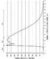
図2は、係る集光の様子を確認するべく行った、レーザービームLBa0のビーム径d1を11(mm)とし、双曲面1bの曲率半径を3.5(mm)としたときの、双曲面レンズ1の頂点1Sからの光軸AX上における距離と光軸AXの位置におけるレーザービームLBb0の強度(任意単位:a.u.)との関係についてのシミュレーションの結果を示す図である。 FIG. 2 is a hyperboloidal surface when the beam diameter d1 of the laser beam LBa0 is set to 11 (mm) and the radius of curvature of the hyperboloidal surface 1b is set to 3.5 (mm). It is a figure which shows the result of a simulation about the relationship between the distance on the optical axis AX from the vertex 1S of the
同様に、図3は、レーザービームLBa0のビーム径d1を3(mm)とし、双曲面1bの曲率半径を1.0(mm)としたときの、双曲面レンズ1の頂点1Sからの光軸AX上における距離と光軸AXの位置におけるレーザービームLBb0の強度(任意単位:a.u.)との関係についてのシミュレーションの結果を示す図である。 Similarly, FIG. 3 shows the optical axis from the apex 1S of the
なお、本実施の形態において示すシミュレーション結果を得るにあたっては、レーザービームLBの波長は1064(nm)としている。 Note that the wavelength of the laser beam LB is set to 1064 (nm) to obtain the simulation result shown in this embodiment.
双曲面1bの相異なる位置から出射されたレーザービームLBb0は原理上、図1に示したように、光軸AX上の所定位置である集光点Fにおいてピンポイントに、強度が最大となるように集光される。 In principle, the laser beam LBb0 emitted from different positions of the hyperboloid 1b is pinned to a maximum intensity at the focal point F, which is a predetermined position on the optical axis AX, as shown in FIG. Is focused on.
ところが、図2および図3に示した結果によれば、レーザービームLBa0を双曲面レンズ1に入射させることによって得られるレーザービームLBb0のプロファイルは、概略、双曲面レンズ1の頂点1Sに近い側から順に、頂点1Sから離隔するにつれてレーザービームLBb0の強度が急激に増大する増大領域RE1と、強度が概ね最大に保たれ変動も小さい高強度領域RE2と、頂点1Sから離隔するにつれレーザービームLBb0の強度が緩やかに減少する減少領域RE3という3つの領域に大別される。 However, according to the results shown in FIGS. 2 and 3, the profile of the laser beam LBb0 obtained by making the laser beam LBa0 incident on the
特に、図2および図3に示すプロファイルのいずれも、高強度領域RE2は光軸方向において数(mm)〜10(mm)程度の比較的広い範囲を有しており、集光点Fについては、明確には特定し難いものとなっている。 In particular, in both of the profiles shown in FIGS. 2 and 3, the high-intensity region RE2 has a relatively wide range of several (mm) to 10 (mm) in the optical axis direction, and the focusing point F is , It is difficult to identify clearly.
本発明の発明者が鋭意検討したところ、レーザービームLBa0のビーム径d1がDのとき、双曲面レンズ1の双曲面1bの曲率半径を0.15D〜0.4Dとすると、このようなmmオーダーの高強度領域RE2が形成されるとの知見が得られた。 The inventors of the present invention have made earnest studies, and when the beam diameter d1 of the laser beam LBa0 is D and the radius of curvature of the hyperboloid 1b of the
本実施の形態においては、係る高強度領域RE2のような、レーザービームLBb0を双曲面レンズ1によって集光することに伴う光軸方向に沿った強度の大きな領域の形成を、被加工物の深さ方向における加工に利用する。なお、本実施の形態において、被加工物の加工とは、変質領域の形成が例示されるが、アブレーションによる溝形成など、他の加工態様であってもよい。 In the present embodiment, the formation of a region of high intensity along the optical axis along with the converging of the laser beam LBb0 by the
図2および図3に示す結果は、あるビーム径d1のレーザービームLBa0を双曲面レンズ1に入射させることによって光軸上に集光されるレーザービームLBb0の強度が、所定の加工閾値(被加工物に所定の加工を行うのに必要なレーザービームの強度の最小値)以上となる範囲(以下、加工可能強度域)において、均質な加工を同時に行うことが、少なくとも原理的には可能であることを教示する。なお、加工可能強度域と高強度領域RE2とは必ずしも一致する必要はない。 The results shown in FIG. 2 and FIG. 3 indicate that the intensity of the laser beam LBb0 focused on the optical axis by making the laser beam LBa0 having a certain beam diameter d1 incident on the
すなわち、レーザービームLBa0の出力およびビーム径d1を適宜に選択し、該ビーム径d1の大きさに応じた形状(曲率半径)の双曲面1bを有する双曲面レンズ1を採用することによって、レーザービームLBb0の加工可能強度域に被加工物における加工対象領域が含まれるようにすれば、一度のレーザービームLBa0の出射により、深さ方向において加工対象領域全体を同時に加工することが可能となる。 That is, by appropriately selecting the output of the laser beam LBa0 and the beam diameter d1, and adopting the
レーザービームLBa0の波長、出力、ビーム径d1、および、双曲面レンズの曲率半径などは、被加工物の種類に応じて適宜に選択されてよい。 The wavelength of the laser beam LBa0, the output, the beam diameter d1, the radius of curvature of the hyperboloid lens, and the like may be appropriately selected according to the type of the workpiece.
なお、実際に被加工物を加工する際には、被加工物の屈折率nも考慮して、加工可能強度域に被加工物における加工対象領域が含まれるようにする必要がある。 When actually processing a workpiece, it is necessary to consider the refractive index n of the workpiece so that the workable strength region includes the processing target region of the workpiece.
<レーザービームの照射範囲の制限>
上述のように、双曲面レンズ1を用いてレーザービームLBb0を集光することにより、被加工物の深さ方向につき同時加工が可能となるが、一方で、加工可能強度域には該当しないため加工はされないものの、レーザービームLBb0自体は弱いながらも照射される領域が存在する。係る照射に起因した何らかの悪影響が生じる可能性を懸念して、このような領域にレーザービームLBb0が照射されることを避けたい、という技術上の要請がある。<Limitation of laser beam irradiation range>
As described above, by converging the laser beam LBb0 using the
本実施の形態においては、係る要請につき、開口絞りを用いてレーザービームLBb0の照射範囲を限定することによって対応する。 In the present embodiment, such a request is met by limiting the irradiation range of the laser beam LBb0 using an aperture stop.
図4は、図1に模式的に示したレーザービームLBb0を集光させる構成に、開口絞り3を追加した構成を示す図である。 FIG. 4 is a diagram showing a configuration in which an
開口絞り3は、光軸方向において光源2と双曲面レンズ1との間に配置される。開口絞り3としては、開口径φがレーザービームLBa0のビーム径d1よりも小さいものが用いられる。 The
係る態様にて開口絞り3が配置されることで、双曲面レンズ1の平坦面1aに実際に入射するレーザービームLBa1のビーム径d3は、光源2から出射された時点におけるレーザービームLBa0のビーム径d1よりも絞られる(小さくなる)。係る場合、レーザービームLBb1のプロファイル形状には、特に、減少領域RE3における形状には、相違が生じる。 By arranging the
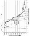
図5は、係る集光の様子を確認するべく行った、レーザービームLBa1のビーム径d1を11(mm)とし、双曲面1bの曲率半径を3.5mmとし、開口絞り3を設けない場合と、開口絞り3の開口径φを7(mm)、8(mm)、10(mm)、および11(mm)の4水準に違えたときの、それぞれのレーザービームLBb1についての、双曲面レンズ1の頂点1Sからの光軸AX上における距離と光軸AXの位置における強度(任意単位:a.u.)との関係についてのシミュレーションの結果を示す図である。なお、開口絞り3を設けない場合のプロファイルは、図2に示したレーザービームLBb0のプロファイルと同じである。 FIG. 5 shows a case where the beam diameter d1 of the laser beam LBa1 is 11 (mm), the radius of curvature of the hyperboloid 1b is 3.5 mm, and the
同様に、図6は、レーザービームLBa1のビーム径d1を3(mm)とし、双曲面1bの曲率半径を1.0mmとしたときの、開口絞り3を設けない場合と、開口絞り3の開口径φを2.2(mm)、2.5(mm)、3(mm)、3.5(mm)、4(mm)、および5(mm)の6水準に違えたときの、それぞれのレーザービームLBb1についての、双曲面レンズ1の頂点1Sからの光軸AX上における距離と光軸AXの位置における強度(任意単位:a.u.)との関係についてのシミュレーションの結果を示す図である。なお、開口絞り3を設けない場合の結果は、図3に示したレーザービームLBb0のプロファイルと同じである。 Similarly, in FIG. 6, when the beam diameter d1 of the laser beam LBa1 is 3 (mm) and the radius of curvature of the hyperboloid 1b is 1.0 mm, the case where the
図5および図6のいずれの場合も、増大領域RE1と高強度領域RE2については、開口絞り3を設けない場合のプロファイル形状が開口絞り3を設けた場合においても維持されているのに対して、減少領域RE3においては、開口絞り3を設けない場合の緩やかな減少とは異なり、所定の位置においてレーザービームLBb1の強度が急激に減衰し、当該位置以遠においては、ゼロになっている。すなわち、レーザービームLBb1がカットされている。また、開口径φの値を小さくするほど、減衰位置は双曲面レンズ1に近づいている。 In both cases of FIG. 5 and FIG. 6, with respect to the increased region RE1 and the high intensity region RE2, the profile shape when the
このことを利用すれば、レーザービームLBb1を用いて被加工物を深さ方向の所定範囲について加工する場合に、加工対象領域よりも深い位置にまでレーザービームLBb1が照射されることを、好適に抑制することが出来る。 If this is utilized, it is preferable that the laser beam LBb1 is irradiated to a position deeper than the processing target region when the workpiece is processed in a predetermined range in the depth direction using the laser beam LBb1. Can be suppressed.
例えば、図5に示すビーム径d1が11(mm)の場合において、強度が150(a.u.)以上の範囲を加工可能強度域とした場合、開口絞り3の開口径φを7(mm)とすれば、双曲面レンズ1の頂点1Sからの距離が約20(mm)の位置がレーザービームLBbの減衰位置となり、当該位置以遠には、レーザービームLBbは照射されない。そして、増大領域RE1の一部を含む当該距離が8.5(mm)〜約20(mm)の範囲が、(被加工物の屈折率を考慮しない場合の)加工可能強度域P1となる。 For example, when the beam diameter d1 shown in FIG. 5 is 11 (mm) and the intensity range of 150 (au) or more is set as the processable intensity range, the aperture diameter φ of the
同様に、図6に示すビーム径d1が3(mm)の場合において、強度が700(a.u.)以上の範囲を加工可能強度域とした場合、開口絞り3の開口径φを2.2(mm)とすれば、双曲面レンズ1の頂点1Sからの距離が約6.2(mm)の位置がレーザービームLBbの減衰位置となり、当該位置以遠には、レーザービームLBbは照射されない。そして、減少領域RE3の一部を含む当該距離が2.5(mm)〜約6.2(mm)の範囲が、(被加工物の屈折率を考慮しない場合の)加工可能強度域P2となる。 Similarly, when the beam diameter d1 shown in FIG. 6 is 3 (mm) and the intensity range of 700 (au) or more is the processable intensity region, the aperture diameter φ of the
これら図5および図6に示す結果からは、あるビーム径d1のレーザービームLBa0を所定の開口径φの開口絞り3にて絞ったうえで双曲面レンズ1に入射させ、これによって双曲面レンズ1から出射されるレーザービームLBb1を、被加工物の所定位置において集光すれば、光軸方向に相当する被加工物の深さ方向において、レーザービームLBb1の加工可能強度域を開口径φに応じた所定範囲に制限し、当該所定範囲においては均質な加工(例えば変質領域の形成)を同時に行う一方で、当該所定範囲以遠にはレーザービームLBb1を照射させないようにすることが、少なくとも原理的には可能であることが教示される。 From the results shown in FIGS. 5 and 6, the laser beam LBa0 having a certain beam diameter d1 is narrowed down by the
本発明の発明者が鋭意検討したところ、レーザービームLBa0のビーム径d1をDとし、双曲面レンズ1の双曲面1bの曲率半径を0.15D〜0.4Dとするとき、開口絞り3の開口径φを0.6D〜0.9Dとすることによって、レーザービームLBb1の加工可能強度域を開口径φに応じた所定範囲に制限できるとの知見が得られた。 The inventors of the present invention have earnestly studied and found that when the beam diameter d1 of the laser beam LBa0 is D and the radius of curvature of the hyperboloid 1b of the
すなわち、レーザービームLBa0の出力およびビーム径d1と、双曲面レンズ1の双曲面1bの曲率半径と、開口絞り3の開口径φとを適宜に選択し、かつ、被加工物の屈折率nも考慮しつつ被加工物における加工対象領域の位置を適宜に調整することによって、一度のレーザービームLBa0の出射により、深さ方向において加工対象領域全体を同時に加工する一方で、加工対象領域以遠にはレーザービームLBb1を照射させないことが、可能となる。 That is, the output and beam diameter d1 of the laser beam LBa0, the radius of curvature of the hyperboloid 1b of the
<装置構成例>
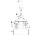
図7は、以上のような原理に基づいて被加工物Wの加工を行うレーザー加工装置100の構成の一例を、模式的に示す図である。<Device configuration example>
FIG. 7 is a diagram schematically showing an example of the configuration of the
レーザー加工装置100は、上述した双曲面レンズ1、光源2、および開口絞り3に加えて、ステージ4と縮小レンズ5とをさらに、主たる構成要素として備える。 The
ステージ4は、被加工物Wが載置固定される水平な被載置面を有してなる。そして、レーザー加工装置100においては、ステージ4に載置された被加工物Wに対して鉛直上方から、双曲面レンズ1によって集光されたレーザービームLBb2が照射されるようになっている。それゆえ、双曲面レンズ1、光源2、および開口絞り3は、図4に示された相互の配置関係をみたしつつも光軸方向が鉛直方向と一致するように、配置されてなる。いま、係る配置がなされた結果として、光源2から鉛直下方に向けて出射されるレーザービームLBa2が、開口絞り3によって絞られてレーザービームLBa3として双曲面レンズ1に入射し、これにより双曲面レンズ1から出射されたレーザービームLBb2が集光されることによって、双曲面レンズ1の頂点1Sから距離z1だけ離隔した位置を起点とする長さS1の範囲に、最大幅w1の加工可能強度域RE4が形成されるものとする。 The
好ましくは、ステージ4は、図示しない駆動機構よって駆動されることにより、水平面内における並進移動(2軸移動)および回転移動と、鉛直方向における昇降移動とが可能に設けられる。これにより、被加工物Wにおける加工対象領域の位置決めや、被加工物Wを移動させつつ加工を行う走査加工などが可能となる。 Preferably, the
ただし、レーザー加工装置100においては、上述の態様にて集光されたレーザービームLBb2がなす加工可能強度域RE4が直接に被加工物Wの加工に寄与するのではなく、縮小レンズ5を含む縮小光学系にて縮小再結像された2次加工可能強度域RE4αが、被加工物Wの加工に寄与するようになっている。 However, in the
縮小レンズ5は、双曲面レンズ1とステージ4の間に(より詳細には、被加工物Wがステージ4に載置固定された状態においては被加工物Wと双曲面レンズ1の間に位置するように)配置されてなる。 The
より詳細には、縮小レンズ5の焦点距離をfとし、加工可能強度域RE4の形成位置と縮小レンズ5との距離をaとし、縮小レンズ5と2次加工可能強度域RE4αの形成位置との距離をb(<a)とし、1/f=(1/a)+(1/b)なる関係をみたす場合、加工可能強度域RE4が縮小再結像されることによって、長さS2=(b/a)2S1の範囲に最大幅w2=(b/a)w1を有する2次加工可能強度域RE4αが形成される。More specifically, the focal length of the
ただし、加工可能強度域RE4におけるレーザービームLBb2のエネルギーは2次加工可能強度域RE4αにおいても実質的に維持されるため、2次加工可能強度域RE4αの単位面積あたりの強度は加工可能強度域RE4の強度よりも大きくなっている。 However, since the energy of the laser beam LBb2 in the machinable intensity range RE4 is substantially maintained in the secondary machinable intensity range RE4α, the intensity per unit area of the secondary machinable intensity range RE4α is the machinable intensity range RE4. Is greater than the strength of.
すなわち、レーザー加工装置100においては、縮小再結像を行わない場合に比して、加工可能強度域RE4における単位面積あたりの強度がより大きいレーザービームLBb2を、局所的に(ピンポイントに)照射することが、可能となっている。 That is, in the
このことは、加工可能強度域に隣接する、強度が所定の加工閾値に満たない領域がより狭められることを、意味している。これにより、加工対象領域以外に強度の弱いレーザービームLBbが照射されてしまうことに起因した不具合の発生が好適に抑制される。 This means that a region adjacent to the machinable strength region and having a strength less than a predetermined machining threshold is narrowed further. As a result, it is possible to suitably suppress the occurrence of a defect caused by the irradiation of the laser beam LBb having a low intensity to the area other than the processing target area.
また、2次加工可能強度域RE4αにおけるレーザービームLBb2の強度が加工閾値を超えていさえすれば加工はなされるので、単位面積あたりの強度が大きい分、加工可能強度域RE4において被加工物Wの加工に用いる場合に比して、光源2から出射させるレーザービームLBa2の出力を小さくしたとしても、所望の加工可能強度域を得ることが出来る。 Further, since the processing is performed as long as the intensity of the laser beam LBb2 in the secondary processable intensity range RE4α exceeds the processing threshold, the intensity per unit area is large, so that the workpiece W is processed in the processable intensity range RE4. Even if the output of the laser beam LBa2 emitted from the
例えば、図6によれば、光源2から出射されるレーザービームLB2のビーム径が3(mm)の場合、仮に開口絞り3として開口径φが2.2(mm)のものを用いたとしても、加工可能強度域RE4の光軸方向における長さS1は4(mm)〜5(mm)程度となる(被加工物Wの屈折率は考慮せず)。それゆえ、被加工物Wの厚みが1(mm)程度であると、照射不要な範囲にまでレーザービームLBbが照射されてしまうことになるが、レーザー加工装置100においては、縮小レンズ5の焦点距離fおよび配置位置を好適に定めることにより、2次加工可能強度域RE4αの深さ方向における長さS2を被加工物Wの厚みと同じ1(mm)程度にすることが可能となる。 For example, according to FIG. 6, when the beam diameter of the laser beam LB2 emitted from the
さらに、レーザー加工装置100においては、例えば図7に示すように、被加工物W内部の、表面から所定の距離z3離隔した位置以遠が加工対象領域とされるような場合であっても、好適に加工を行うことが可能となる。係る場合においては、被加工物Wの表面から距離z3の範囲に、レーザービームLBb2が実質的に照射されないような加工も可能である。 Further, in the
好ましくは、縮小レンズ5は、図示しない駆動機構によって、鉛直方向に移動自在とされてなる。係る場合、被加工物の厚みが薄い場合など、被加工物の深さ方向における加工対象領域のサイズが小さいような場合でも、縮小レンズ5を移動させることによって距離a、bの比率を適宜に調整することにより、当該加工対象領域のみを加工可能強度域と一致させて加工を行えることを、意味している。 Preferably, the
なお、光源2から出射されるレーザービームLBa2のビーム径を小さくすることや、開口絞り3の開口径φを小さくすることによって、加工可能強度域を狭める態様も考えられる。しかしながら、前者については、実用される加工用レーザービームのビーム径の下限値が概ね2(mm)〜3(mm)であることを考えると現実的ではない。また、後者については、開口径φを小さくしすぎると、図5および図6に示すような強度プロファイルにおいて、ピーク近傍ひいてはピーク部分そのものをカットすることになり、コスト面や、光学部品へのダメージという点から好ましくないない。 Note that a mode in which the machinable strength region is narrowed by reducing the beam diameter of the laser beam LBa2 emitted from the
一方で、縮小レンズ5を用いることは、被加工物Wと双曲面レンズ1との距離を確保する効果もある。すなわち、図2および図3からわかるように、ビーム径が数(mm)程度のレーザービームLB2を双曲面レンズ1に入射させることによって形成される高強度領域RE2が最大強度となるのは、双曲面レンズ1の頂点1Sからせいぜい数(mm)〜十数(mm)程度離隔した位置に過ぎないため、加工可能強度域RE4をそのまま加工に用いる場合、装置の作動距離が十分に確保されず、被加工物Wにおける加工対象領域の位置および範囲によっては、加工の実施そのものが不可能あるいは困難な場合がある。あるいは、加工の際に生じる飛散物が双曲面レンズ1に付着してしまうなどの不具合が生じる可能性もある。 On the other hand, using the
これに対し、本実施の形態に係るレーザー加工装置100においては、縮小レンズ5を用いることによって、被加工物Wと近接するのは双曲面レンズ1ではなく縮小レンズ5となるが、距離a、距離bおよび焦点距離fを好適に定めることによって、装置の作動距離を十分に確保することが可能である。 On the other hand, in the
図8は、図5に示した、レーザービームLBa1のビーム径d1を11(mm)とし、双曲面1bの曲率半径を3.5(mm)とし、開口絞り3の開口径φを7(mm)および8(mm)とした構成に、焦点距離f=27(mm)の縮小レンズ5(厚み0の無収差レンズ)を付加した構成によって、b/aの値をおよそ1/4として縮小再結像したレーザービームLBb2の、縮小レンズ5からの光軸AX上における距離と光軸AXの位置における強度(任意単位:a.u.)との関係についてのシミュレーション結果を示す図である。 In FIG. 8, the beam diameter d1 of the laser beam LBa1 shown in FIG. 5 is 11 (mm), the radius of curvature of the hyperboloid 1b is 3.5 (mm), and the aperture diameter φ of the
また、図9は、図6に示した、レーザービームLBa1のビーム径d1を3(mm)とし、双曲面1bの曲率半径を1.0(mm)とし、開口絞り3の開口径φを2.2(mm)、3(mm)、4(mm)とした構成に、焦点距離f=27(mm)の縮小レンズ5(厚み0の無収差レンズ)を付加した構成によって、b/aの値をおよそ1/4として縮小再結像したレーザービームLBb2の、縮小レンズ5からの光軸AX上における距離と光軸AXの位置における強度(任意単位:a.u.)との関係についてのシミュレーション結果を示す図である。 In addition, in FIG. 9, the beam diameter d1 of the laser beam LBa1 shown in FIG. 6 is 3 (mm), the radius of curvature of the hyperboloid 1b is 1.0 (mm), and the aperture diameter φ of the
図8および図9のいずれにおいても、プロファイルの幅はせいぜい1(mm)という、図5および図6に示したプロファイルに比して十分に小さい((1/4)2=1/16程度の)値となっている。一方で、最大強度は、図5および図6に示したプロファイルの最大強度に比して十分に大きな(16倍程度の)値となっている。8 and 9, the width of the profile is at most 1 (mm), which is sufficiently smaller than that of the profile shown in FIGS. 5 and 6 (about (1/4)2 =1/16). ) It is a value. On the other hand, the maximum intensity has a sufficiently large value (about 16 times) as compared with the maximum intensity of the profiles shown in FIGS. 5 and 6.
なお、図8および図9においてはプロファイルの立ち上がりが図5および図6に示したプロファイルよりも緩やかになっているが、これは、縮小レンズ5がない場合に比して収差の影響が大きいためであると考えられる。 8 and 9, the rise of the profile is slower than that of the profile shown in FIGS. 5 and 6, but this is because the influence of aberration is larger than that in the case where the
さらに、縮小レンズからの33.7(mm)〜33.8(mm)程度離れた位置において、強度が最大となっていることがわかる。これは、作動距離が十分に確保されることを意味する。 Furthermore, it can be seen that the intensity is maximum at a position about 33.7 (mm) to 33.8 (mm) away from the reduction lens. This means that a sufficient working distance is ensured.
以上、説明したように、本実施の形態によれば、双曲面レンズにレーザービームを入射させてレーザービームを集光することにより、被加工物の深さ方向につき同時加工が可能となる。レーザービームのビーム径と双曲面レンズの双曲面における曲率半径を適宜に選択し、かつ、被加工物における加工対象領域の位置を適宜に調整することによって、集光されるレーザービームの加工可能強度域に被加工物における加工対象領域が含まれるようにすれば、一度のレーザービームの出射により、深さ方向において加工対象領域全体を同時に加工することが可能となる。 As described above, according to the present embodiment, the laser beam is made incident on the hyperboloidal lens to focus the laser beam, whereby simultaneous processing in the depth direction of the workpieces becomes possible. The processable intensity of the focused laser beam by appropriately selecting the beam diameter of the laser beam and the radius of curvature of the hyperboloid of the hyperboloid lens and adjusting the position of the processing target area on the workpiece. If the region includes the region to be processed in the workpiece, it is possible to simultaneously process the entire region to be processed in the depth direction by emitting the laser beam once.
加えて、レーザービームをビーム径に応じた開口径の開口絞りにて絞ったうえで双曲面レンズに入射させることにより、加工対象領域以遠にはレーザービームを照射させないことが、可能となる。 In addition, by narrowing the laser beam with an aperture stop having an aperture diameter corresponding to the beam diameter and then making it enter the hyperboloid lens, it is possible to prevent the laser beam from being irradiated beyond the region to be processed.
さらには、いったん集光させたレーザービームそのものではなく、係るレーザービームを縮小レンズにて縮小再結像させたレーザービームを加工に用いるようにすることで、単位面積あたりの強度が大きいレーザービームを局所的に照射することが可能となるほか、縮小再結像を行わない場合に比して、作動距離を大きくすることが出来る。 In addition, a laser beam with a large intensity per unit area can be obtained by using a laser beam that is refocused by a reduction lens for processing instead of the laser beam that is once focused. It is possible to irradiate locally, and the working distance can be increased as compared with the case where reduction reimaging is not performed.
1 双曲面レンズ
1S (双曲面レンズの)頂点
1a (双曲面レンズの)平坦面
1b (双曲面レンズの)双曲面
2 光源
3 開口絞り
4 ステージ
5 縮小レンズ
100 レーザー加工装置
AX 光軸
LB(LB0、LB1、LB2、LB3、LBa、LBb) レーザービーム
P1、P2 加工可能強度域
RE1 増大領域
RE2 高強度領域
RE2α 2次高強度領域
RE3 減少領域
W 被加工物DESCRIPTION OF
Claims (6)
Translated fromJapanese前記レーザービームを出射可能な光源と、
前記光源から出射される前記レーザービームの光軸上に配置された双曲面レンズと、
を備え、
前記レーザービームのビーム径をDとするとき、前記双曲面レンズの双曲面の曲率半径が0.15D〜0.4Dなる値を有してなり、
前記レーザービームが前記双曲面レンズによって集光されることにより形成される、前記レーザービームの強度が所定の加工閾値以上となる加工可能強度域に、前記被加工物の加工対象領域を含めることによって、前記被加工物を加工する、
ことを特徴とする、レーザー加工装置。A laser processing apparatus for processing a workpiece using a laser beam,
A light source capable of emitting the laser beam,
A hyperboloid lens arranged on the optical axis of the laser beam emitted from the light source,
Equipped with
When the beam diameter of the laser beam is D, the hyperbolic curvature radius of the hyperboloid lens has a value of 0.15D to 0.4D,
By including a processing target region of the workpiece in a machinable intensity region in which the intensity of the laser beam is equal to or higher than a predetermined machining threshold, which is formed by condensing the laser beam by the hyperboloid lens Processing the workpiece,
A laser processing device characterized in that
前記光源と前記双曲面レンズの間に配置されてなり、0.6D〜0.9Dなる値の開口径を有する開口絞り、
をさらに備え、
前記開口絞りによって前記ビーム径が絞られた前記レーザービームが前記双曲面レンズによって集光されることにより形成される前記加工可能強度域に、前記加工対象領域を含めることによって、前記被加工物を加工する、
ことを特徴とする、レーザー加工装置。The laser processing apparatus according to claim 1, wherein
An aperture stop arranged between the light source and the hyperboloid lens, having an aperture diameter of 0.6D to 0.9D,
Further equipped with,
By including the processing target region in the processable intensity region formed by focusing the laser beam whose beam diameter is narrowed by the aperture stop by the hyperboloid lens, To process,
A laser processing device characterized in that
前記双曲面レンズと前記被加工物の配置位置との間に配置されてなり、前記加工可能強度域を縮小再結像させる縮小レンズ、
をさらに備え、
前記縮小レンズによって縮小再結像された前記加工可能強度域に前記加工対象領域を含めることによって、前記被加工物を加工する、
ことを特徴とする、レーザー加工装置。The laser processing apparatus according to claim 1 or 2, wherein
A reduction lens which is arranged between the hyperboloid lens and the arrangement position of the workpiece, and which reduces and re-images the processable intensity region,
Further equipped with,
Processing the workpiece by including the processing target region in the processable intensity region that has been reimaged by the reduction lens.
A laser processing device characterized in that
所定の光源から出射される、ビーム径Dのレーザービームの光軸上に、双曲面の曲率半径が0.15D〜0.4Dなる値である双曲面レンズを配置し、
前記レーザービームが前記双曲面レンズによって集光されることにより形成される、前記レーザービームの強度が所定の加工閾値以上となる加工可能強度域に、前記被加工物の加工対象領域を含めることによって、前記被加工物を加工する、
ことを特徴とする、被加工物の加工方法。A method of processing a workpiece using a laser beam,
A hyperboloid lens having a hyperbolic curvature radius of 0.15D to 0.4D is arranged on the optical axis of a laser beam having a beam diameter D emitted from a predetermined light source.
By including a processing target region of the workpiece in a machinable intensity region in which the intensity of the laser beam is equal to or higher than a predetermined machining threshold, which is formed by condensing the laser beam by the hyperboloid lens Processing the workpiece,
A method for processing a workpiece, which is characterized in that
前記光源と前記双曲面レンズの間に、0.6D〜0.9Dなる値の開口径を有する開口絞りを配置し、
前記開口絞りによって前記ビーム径が絞られた前記レーザービームが前記双曲面レンズによって集光されることにより形成される前記加工可能強度域に、前記加工対象領域を含めることによって、前記被加工物を加工する、
ことを特徴とする、被加工物の加工方法。A method for processing a work piece according to claim 4,
An aperture stop having an aperture diameter of 0.6D to 0.9D is arranged between the light source and the hyperboloid lens,
By including the processing target region in the processable intensity region formed by focusing the laser beam whose beam diameter is narrowed by the aperture stop by the hyperboloid lens, To process,
A method for processing a workpiece, which is characterized in that
前記双曲面レンズと前記被加工物の配置位置との間に前記加工可能強度域を縮小再結像させる縮小レンズを配置し、
前記縮小レンズによって縮小再結像された前記加工可能強度域に前記加工対象領域を含めることによって、前記被加工物を加工する、
ことを特徴とする、被加工物の加工方法。A method for processing a workpiece according to claim 4 or 5, wherein
A reduction lens for reducing and re-imaging the processable intensity region is arranged between the hyperboloid lens and the arrangement position of the workpiece,
Processing the workpiece by including the processing target region in the processable intensity region that has been reimaged by the reduction lens.
A method for processing a workpiece, which is characterized in that
Priority Applications (4)
| Application Number | Priority Date | Filing Date | Title |
|---|---|---|---|
| JP2018223160AJP2020082162A (en) | 2018-11-29 | 2018-11-29 | Laser processing device and method for processing work-piece |
| TW108137238ATW202022409A (en) | 2018-11-29 | 2019-10-16 | Laser processing apparatus and processing method of processed object including a light source emitting a laser beam and a hyperboloid lens arranged on an optical axis of the laser beam emitted from the light source |
| KR1020190137305AKR20200064897A (en) | 2018-11-29 | 2019-10-31 | Laser Processing Apparatus and Processing Method of Processed Products |
| CN201911142495.0ACN111230289A (en) | 2018-11-29 | 2019-11-20 | Laser processing device and processing method of processed object |
Applications Claiming Priority (1)
| Application Number | Priority Date | Filing Date | Title |
|---|---|---|---|
| JP2018223160AJP2020082162A (en) | 2018-11-29 | 2018-11-29 | Laser processing device and method for processing work-piece |
Publications (1)
| Publication Number | Publication Date |
|---|---|
| JP2020082162Atrue JP2020082162A (en) | 2020-06-04 |
Family
ID=70875774
Family Applications (1)
| Application Number | Title | Priority Date | Filing Date |
|---|---|---|---|
| JP2018223160AAbandonedJP2020082162A (en) | 2018-11-29 | 2018-11-29 | Laser processing device and method for processing work-piece |
Country Status (4)
| Country | Link |
|---|---|
| JP (1) | JP2020082162A (en) |
| KR (1) | KR20200064897A (en) |
| CN (1) | CN111230289A (en) |
| TW (1) | TW202022409A (en) |
Family Cites Families (1)
| Publication number | Priority date | Publication date | Assignee | Title |
|---|---|---|---|---|
| WO2014079478A1 (en) | 2012-11-20 | 2014-05-30 | Light In Light Srl | High speed laser processing of transparent materials |
- 2018
- 2018-11-29JPJP2018223160Apatent/JP2020082162A/ennot_activeAbandoned
- 2019
- 2019-10-16TWTW108137238Apatent/TW202022409A/enunknown
- 2019-10-31KRKR1020190137305Apatent/KR20200064897A/ennot_activeWithdrawn
- 2019-11-20CNCN201911142495.0Apatent/CN111230289A/ennot_activeWithdrawn
Also Published As
| Publication number | Publication date |
|---|---|
| CN111230289A (en) | 2020-06-05 |
| TW202022409A (en) | 2020-06-16 |
| KR20200064897A (en) | 2020-06-08 |
Similar Documents
| Publication | Publication Date | Title |
|---|---|---|
| JP4490883B2 (en) | Laser processing apparatus and laser processing method | |
| KR101798172B1 (en) | Laser beam working machine | |
| JP2015519722A (en) | Laser scribing with high depth action in the workpiece | |
| JP2004528991A5 (en) | ||
| JP6680494B2 (en) | Laser processing method and laser processing apparatus | |
| US20150060421A1 (en) | Laser annealing apparatus and laser annealing method | |
| JP2014231071A (en) | Substrate cutting device by using laser beam | |
| JP2010274328A (en) | Laser beam machining method and laser beam machining device | |
| JP2008036641A (en) | Laser beam machining apparatus and method | |
| JP2018051567A (en) | Laser processing apparatus and laser processing method | |
| JP6752232B2 (en) | How to cut the object to be processed | |
| JP2020082139A (en) | Laser processing device and method for processing work-piece | |
| JP6744624B2 (en) | Method and apparatus for cutting tubular brittle member | |
| JP2020082162A (en) | Laser processing device and method for processing work-piece | |
| JP2007029952A (en) | Laser beam machining apparatus, and laser beam machining method | |
| KR20180013678A (en) | Method and apparatus for laser processing substrate of brittle material | |
| KR101445832B1 (en) | Laser processing apparatus and laser processing method | |
| US20160001397A1 (en) | Laser processing apparatus | |
| CN106994562A (en) | Laser cutting method and laser cutting machine for hard and brittle materials | |
| JP6430816B2 (en) | Laser processing device setting device, laser processing device including the same, and laser processing device setting program | |
| KR20130125438A (en) | Laser machine using ultra - short pulse laser by single photon absorption | |
| JP2018065146A (en) | Laser processing method and laser processing apparatus | |
| US11123822B2 (en) | Manufacturing method for glass substrate, method for forming hole in glass substrate, and apparatus for forming hole in glass substrate | |
| KR20130052062A (en) | Laser machine using ultra - short pulse laser by single photon absorption | |
| JP7383340B2 (en) | laser processing equipment |
Legal Events
| Date | Code | Title | Description |
|---|---|---|---|
| A621 | Written request for application examination | Free format text:JAPANESE INTERMEDIATE CODE: A621 Effective date:20211018 | |
| A762 | Written abandonment of application | Free format text:JAPANESE INTERMEDIATE CODE: A762 Effective date:20220812 | |
| A977 | Report on retrieval | Free format text:JAPANESE INTERMEDIATE CODE: A971007 Effective date:20220831 |