JP2020078579A - Low magnetic field magnetic resonance imaging method and device - Google Patents
Low magnetic field magnetic resonance imaging method and deviceDownload PDFInfo
- Publication number
- JP2020078579A JP2020078579AJP2020025749AJP2020025749AJP2020078579AJP 2020078579 AJP2020078579 AJP 2020078579AJP 2020025749 AJP2020025749 AJP 2020025749AJP 2020025749 AJP2020025749 AJP 2020025749AJP 2020078579 AJP2020078579 AJP 2020078579A
- Authority
- JP
- Japan
- Prior art keywords
- magnetic
- coil
- coils
- laminate
- panel
- Prior art date
- Legal status (The legal status is an assumption and is not a legal conclusion. Google has not performed a legal analysis and makes no representation as to the accuracy of the status listed.)
- Granted
Links
Images


Classifications
- G—PHYSICS
- G01—MEASURING; TESTING
- G01R—MEASURING ELECTRIC VARIABLES; MEASURING MAGNETIC VARIABLES
- G01R33/00—Arrangements or instruments for measuring magnetic variables
- G01R33/20—Arrangements or instruments for measuring magnetic variables involving magnetic resonance
- G01R33/28—Details of apparatus provided for in groups G01R33/44 - G01R33/64
- G01R33/38—Systems for generation, homogenisation or stabilisation of the main or gradient magnetic field
- G01R33/3802—Manufacture or installation of magnet assemblies; Additional hardware for transportation or installation of the magnet assembly or for providing mechanical support to components of the magnet assembly
- G—PHYSICS
- G01—MEASURING; TESTING
- G01R—MEASURING ELECTRIC VARIABLES; MEASURING MAGNETIC VARIABLES
- G01R33/00—Arrangements or instruments for measuring magnetic variables
- G01R33/20—Arrangements or instruments for measuring magnetic variables involving magnetic resonance
- G01R33/28—Details of apparatus provided for in groups G01R33/44 - G01R33/64
- G01R33/38—Systems for generation, homogenisation or stabilisation of the main or gradient magnetic field
- G01R33/3804—Additional hardware for cooling or heating of the magnet assembly, for housing a cooled or heated part of the magnet assembly or for temperature control of the magnet assembly
- G—PHYSICS
- G01—MEASURING; TESTING
- G01R—MEASURING ELECTRIC VARIABLES; MEASURING MAGNETIC VARIABLES
- G01R33/00—Arrangements or instruments for measuring magnetic variables
- G01R33/20—Arrangements or instruments for measuring magnetic variables involving magnetic resonance
- G01R33/28—Details of apparatus provided for in groups G01R33/44 - G01R33/64
- G01R33/32—Excitation or detection systems, e.g. using radio frequency signals
- G01R33/34—Constructional details, e.g. resonators, specially adapted to MR
- G01R33/34007—Manufacture of RF coils, e.g. using printed circuit board technology; additional hardware for providing mechanical support to the RF coil assembly or to part thereof, e.g. a support for moving the coil assembly relative to the remainder of the MR system
- G—PHYSICS
- G01—MEASURING; TESTING
- G01R—MEASURING ELECTRIC VARIABLES; MEASURING MAGNETIC VARIABLES
- G01R33/00—Arrangements or instruments for measuring magnetic variables
- G01R33/20—Arrangements or instruments for measuring magnetic variables involving magnetic resonance
- G01R33/28—Details of apparatus provided for in groups G01R33/44 - G01R33/64
- G01R33/32—Excitation or detection systems, e.g. using radio frequency signals
- G01R33/36—Electrical details, e.g. matching or coupling of the coil to the receiver
- G01R33/3614—RF power amplifiers
- G—PHYSICS
- G01—MEASURING; TESTING
- G01R—MEASURING ELECTRIC VARIABLES; MEASURING MAGNETIC VARIABLES
- G01R33/00—Arrangements or instruments for measuring magnetic variables
- G01R33/20—Arrangements or instruments for measuring magnetic variables involving magnetic resonance
- G01R33/28—Details of apparatus provided for in groups G01R33/44 - G01R33/64
- G01R33/38—Systems for generation, homogenisation or stabilisation of the main or gradient magnetic field
- G01R33/383—Systems for generation, homogenisation or stabilisation of the main or gradient magnetic field using permanent magnets
- G—PHYSICS
- G01—MEASURING; TESTING
- G01R—MEASURING ELECTRIC VARIABLES; MEASURING MAGNETIC VARIABLES
- G01R33/00—Arrangements or instruments for measuring magnetic variables
- G01R33/20—Arrangements or instruments for measuring magnetic variables involving magnetic resonance
- G01R33/28—Details of apparatus provided for in groups G01R33/44 - G01R33/64
- G01R33/38—Systems for generation, homogenisation or stabilisation of the main or gradient magnetic field
- G01R33/385—Systems for generation, homogenisation or stabilisation of the main or gradient magnetic field using gradient magnetic field coils
- G01R33/3852—Gradient amplifiers; means for controlling the application of a gradient magnetic field to the sample, e.g. a gradient signal synthesizer
- G—PHYSICS
- G01—MEASURING; TESTING
- G01R—MEASURING ELECTRIC VARIABLES; MEASURING MAGNETIC VARIABLES
- G01R33/00—Arrangements or instruments for measuring magnetic variables
- G01R33/20—Arrangements or instruments for measuring magnetic variables involving magnetic resonance
- G01R33/28—Details of apparatus provided for in groups G01R33/44 - G01R33/64
- G01R33/38—Systems for generation, homogenisation or stabilisation of the main or gradient magnetic field
- G01R33/385—Systems for generation, homogenisation or stabilisation of the main or gradient magnetic field using gradient magnetic field coils
- G01R33/3854—Systems for generation, homogenisation or stabilisation of the main or gradient magnetic field using gradient magnetic field coils means for active and/or passive vibration damping or acoustical noise suppression in gradient magnet coil systems
- G—PHYSICS
- G01—MEASURING; TESTING
- G01R—MEASURING ELECTRIC VARIABLES; MEASURING MAGNETIC VARIABLES
- G01R33/00—Arrangements or instruments for measuring magnetic variables
- G01R33/20—Arrangements or instruments for measuring magnetic variables involving magnetic resonance
- G01R33/28—Details of apparatus provided for in groups G01R33/44 - G01R33/64
- G01R33/38—Systems for generation, homogenisation or stabilisation of the main or gradient magnetic field
- G01R33/385—Systems for generation, homogenisation or stabilisation of the main or gradient magnetic field using gradient magnetic field coils
- G01R33/3856—Means for cooling the gradient coils or thermal shielding of the gradient coils
- G—PHYSICS
- G01—MEASURING; TESTING
- G01R—MEASURING ELECTRIC VARIABLES; MEASURING MAGNETIC VARIABLES
- G01R33/00—Arrangements or instruments for measuring magnetic variables
- G01R33/20—Arrangements or instruments for measuring magnetic variables involving magnetic resonance
- G01R33/28—Details of apparatus provided for in groups G01R33/44 - G01R33/64
- G01R33/38—Systems for generation, homogenisation or stabilisation of the main or gradient magnetic field
- G01R33/385—Systems for generation, homogenisation or stabilisation of the main or gradient magnetic field using gradient magnetic field coils
- G01R33/3858—Manufacture and installation of gradient coils, means for providing mechanical support to parts of the gradient-coil assembly
- G—PHYSICS
- G01—MEASURING; TESTING
- G01R—MEASURING ELECTRIC VARIABLES; MEASURING MAGNETIC VARIABLES
- G01R33/00—Arrangements or instruments for measuring magnetic variables
- G01R33/20—Arrangements or instruments for measuring magnetic variables involving magnetic resonance
- G01R33/28—Details of apparatus provided for in groups G01R33/44 - G01R33/64
- G01R33/42—Screening
- G01R33/422—Screening of the radio frequency field
- G—PHYSICS
- G01—MEASURING; TESTING
- G01R—MEASURING ELECTRIC VARIABLES; MEASURING MAGNETIC VARIABLES
- G01R33/00—Arrangements or instruments for measuring magnetic variables
- G01R33/20—Arrangements or instruments for measuring magnetic variables involving magnetic resonance
- G01R33/44—Arrangements or instruments for measuring magnetic variables involving magnetic resonance using nuclear magnetic resonance [NMR]
- G01R33/48—NMR imaging systems
- G01R33/54—Signal processing systems, e.g. using pulse sequences ; Generation or control of pulse sequences; Operator console
- G01R33/543—Control of the operation of the MR system, e.g. setting of acquisition parameters prior to or during MR data acquisition, dynamic shimming, use of one or more scout images for scan plane prescription
- G—PHYSICS
- G01—MEASURING; TESTING
- G01R—MEASURING ELECTRIC VARIABLES; MEASURING MAGNETIC VARIABLES
- G01R33/00—Arrangements or instruments for measuring magnetic variables
- G01R33/20—Arrangements or instruments for measuring magnetic variables involving magnetic resonance
- G01R33/44—Arrangements or instruments for measuring magnetic variables involving magnetic resonance using nuclear magnetic resonance [NMR]
- G01R33/48—NMR imaging systems
- G01R33/54—Signal processing systems, e.g. using pulse sequences ; Generation or control of pulse sequences; Operator console
- G01R33/546—Interface between the MR system and the user, e.g. for controlling the operation of the MR system or for the design of pulse sequences
- G—PHYSICS
- G01—MEASURING; TESTING
- G01R—MEASURING ELECTRIC VARIABLES; MEASURING MAGNETIC VARIABLES
- G01R33/00—Arrangements or instruments for measuring magnetic variables
- G01R33/20—Arrangements or instruments for measuring magnetic variables involving magnetic resonance
- G01R33/44—Arrangements or instruments for measuring magnetic variables involving magnetic resonance using nuclear magnetic resonance [NMR]
- G01R33/48—NMR imaging systems
- G01R33/54—Signal processing systems, e.g. using pulse sequences ; Generation or control of pulse sequences; Operator console
- G01R33/56—Image enhancement or correction, e.g. subtraction or averaging techniques, e.g. improvement of signal-to-noise ratio and resolution
- G01R33/5608—Data processing and visualization specially adapted for MR, e.g. for feature analysis and pattern recognition on the basis of measured MR data, segmentation of measured MR data, edge contour detection on the basis of measured MR data, for enhancing measured MR data in terms of signal-to-noise ratio by means of noise filtering or apodization, for enhancing measured MR data in terms of resolution by means for deblurring, windowing, zero filling, or generation of gray-scaled images, colour-coded images or images displaying vectors instead of pixels
- G—PHYSICS
- G01—MEASURING; TESTING
- G01R—MEASURING ELECTRIC VARIABLES; MEASURING MAGNETIC VARIABLES
- G01R33/00—Arrangements or instruments for measuring magnetic variables
- G01R33/20—Arrangements or instruments for measuring magnetic variables involving magnetic resonance
- G01R33/44—Arrangements or instruments for measuring magnetic variables involving magnetic resonance using nuclear magnetic resonance [NMR]
- G01R33/48—NMR imaging systems
- G01R33/54—Signal processing systems, e.g. using pulse sequences ; Generation or control of pulse sequences; Operator console
- G01R33/56—Image enhancement or correction, e.g. subtraction or averaging techniques, e.g. improvement of signal-to-noise ratio and resolution
- G01R33/565—Correction of image distortions, e.g. due to magnetic field inhomogeneities
- G01R33/56518—Correction of image distortions, e.g. due to magnetic field inhomogeneities due to eddy currents, e.g. caused by switching of the gradient magnetic field
- G—PHYSICS
- G01—MEASURING; TESTING
- G01R—MEASURING ELECTRIC VARIABLES; MEASURING MAGNETIC VARIABLES
- G01R33/00—Arrangements or instruments for measuring magnetic variables
- G01R33/20—Arrangements or instruments for measuring magnetic variables involving magnetic resonance
- G01R33/44—Arrangements or instruments for measuring magnetic variables involving magnetic resonance using nuclear magnetic resonance [NMR]
- G01R33/48—NMR imaging systems
- G01R33/58—Calibration of imaging systems, e.g. using test probes, Phantoms; Calibration objects or fiducial markers such as active or passive RF coils surrounding an MR active material
- H—ELECTRICITY
- H01—ELECTRIC ELEMENTS
- H01F—MAGNETS; INDUCTANCES; TRANSFORMERS; SELECTION OF MATERIALS FOR THEIR MAGNETIC PROPERTIES
- H01F7/00—Magnets
- H01F7/02—Permanent magnets [PM]
- H—ELECTRICITY
- H01—ELECTRIC ELEMENTS
- H01F—MAGNETS; INDUCTANCES; TRANSFORMERS; SELECTION OF MATERIALS FOR THEIR MAGNETIC PROPERTIES
- H01F7/00—Magnets
- H01F7/06—Electromagnets; Actuators including electromagnets
- G—PHYSICS
- G01—MEASURING; TESTING
- G01R—MEASURING ELECTRIC VARIABLES; MEASURING MAGNETIC VARIABLES
- G01R33/00—Arrangements or instruments for measuring magnetic variables
- G01R33/20—Arrangements or instruments for measuring magnetic variables involving magnetic resonance
- G01R33/28—Details of apparatus provided for in groups G01R33/44 - G01R33/64
- G01R33/38—Systems for generation, homogenisation or stabilisation of the main or gradient magnetic field
- G01R33/3806—Open magnet assemblies for improved access to the sample, e.g. C-type or U-type magnets
- G—PHYSICS
- G01—MEASURING; TESTING
- G01R—MEASURING ELECTRIC VARIABLES; MEASURING MAGNETIC VARIABLES
- G01R33/00—Arrangements or instruments for measuring magnetic variables
- G01R33/20—Arrangements or instruments for measuring magnetic variables involving magnetic resonance
- G01R33/28—Details of apparatus provided for in groups G01R33/44 - G01R33/64
- G01R33/38—Systems for generation, homogenisation or stabilisation of the main or gradient magnetic field
- G01R33/381—Systems for generation, homogenisation or stabilisation of the main or gradient magnetic field using electromagnets
- G—PHYSICS
- G01—MEASURING; TESTING
- G01R—MEASURING ELECTRIC VARIABLES; MEASURING MAGNETIC VARIABLES
- G01R33/00—Arrangements or instruments for measuring magnetic variables
- G01R33/20—Arrangements or instruments for measuring magnetic variables involving magnetic resonance
- G01R33/28—Details of apparatus provided for in groups G01R33/44 - G01R33/64
- G01R33/38—Systems for generation, homogenisation or stabilisation of the main or gradient magnetic field
- G01R33/387—Compensation of inhomogeneities
- G01R33/3875—Compensation of inhomogeneities using correction coil assemblies, e.g. active shimming
- G—PHYSICS
- G01—MEASURING; TESTING
- G01R—MEASURING ELECTRIC VARIABLES; MEASURING MAGNETIC VARIABLES
- G01R33/00—Arrangements or instruments for measuring magnetic variables
- G01R33/20—Arrangements or instruments for measuring magnetic variables involving magnetic resonance
- G01R33/44—Arrangements or instruments for measuring magnetic variables involving magnetic resonance using nuclear magnetic resonance [NMR]
- G01R33/445—MR involving a non-standard magnetic field B0, e.g. of low magnitude as in the earth's magnetic field or in nanoTesla spectroscopy, comprising a polarizing magnetic field for pre-polarisation, B0 with a temporal variation of its magnitude or direction such as field cycling of B0 or rotation of the direction of B0, or spatially inhomogeneous B0 like in fringe-field MR or in stray-field imaging
Landscapes
- Physics & Mathematics (AREA)
- General Physics & Mathematics (AREA)
- Condensed Matter Physics & Semiconductors (AREA)
- High Energy & Nuclear Physics (AREA)
- Engineering & Computer Science (AREA)
- Signal Processing (AREA)
- Health & Medical Sciences (AREA)
- Electromagnetism (AREA)
- Nuclear Medicine, Radiotherapy & Molecular Imaging (AREA)
- Radiology & Medical Imaging (AREA)
- General Health & Medical Sciences (AREA)
- Power Engineering (AREA)
- Spectroscopy & Molecular Physics (AREA)
- Computer Vision & Pattern Recognition (AREA)
- Artificial Intelligence (AREA)
- Epidemiology (AREA)
- Magnetic Resonance Imaging Apparatus (AREA)
- Coils Or Transformers For Communication (AREA)
- Laminated Bodies (AREA)
- Aeration Devices For Treatment Of Activated Polluted Sludge (AREA)
- Gas Separation By Absorption (AREA)
- Parts Printed On Printed Circuit Boards (AREA)
Abstract
Translated fromJapaneseDescription
Translated fromJapanese磁気共鳴映像法(MRI)は、数多くの用途のために重要な撮像モダリティを提供し、人体の内側の画像を生成するために臨床環境及び研究環境において広く利用されている。一般論として、MRIは、適用される磁場に起因する状態変化に応答して原子によって放出される電磁波である、磁気共鳴(MR)信号を検出することに基づく。例えば、核磁気共鳴(NMR)技法は、撮像される物体内の原子(例えば、人体の組織内の原子)の核スピンの再整列(re-alignment)又は緩和(relaxation)の後に励起される原子の原子核から放射されるMR信号を検出することを含む。検出されるMR信号を処理して画像を生成してよく、画像は、医療用途の脈絡において、診断目的、治療目的、及び/又は研究目的のための、体内の内部構造及び/又は生物学的プロセスの研究を可能にする。 Magnetic resonance imaging (MRI) offers important imaging modalities for numerous applications and is widely used in clinical and research settings to produce images of the inside of the human body. In general terms, MRI is based on detecting magnetic resonance (MR) signals, which are electromagnetic waves emitted by atoms in response to state changes caused by an applied magnetic field. Nuclear magnetic resonance (NMR) techniques, for example, are atoms that are excited after re-alignment or relaxation of the nuclear spins of atoms within the imaged object (eg, atoms within the tissues of the human body). Detecting MR signals emitted from the nuclei of the. The detected MR signal may be processed to produce an image, which is an internal structure and/or biological structure in the body for diagnostic, therapeutic, and/or research purposes in the context of medical applications. Enables study of processes.
MRIは、他のモダリティの安全の懸念を伴わずに(例えば、被験者を電離放射線、例えば、X線に晒すことを必要とせずに、或いは、放射性材料を体に持ち込まずに)、比較的高い解像度及びコントラストを有する非侵襲的画像を生成する能力の故に、生物学的撮像のための魅力的な撮像モダリティを提供する。加えて、MRIは、他の撮像モダリティが成功裡に撮像し得ない対象(subject matter)を撮像するために活用し得る柔組織コントラストを提供するのに特に適する。その上、MR技法は、他のモダリティが取得し得ない構造及び/又は生物学的プロセスについての情報を取り込み得る。しかしながら、従来的なMRI技法には数多くの欠点があり、それらは、所与の撮像用途について、比較的高い機器コスト、限定的な利用可能性(例えば、臨床MRIスキャナへのアクセスを得ることの困難及び費用)、画像取得プロセスの長さ等を含むことがある。 MRI is relatively high without the safety concerns of other modalities (eg, without requiring the subject to be exposed to ionizing radiation, eg, X-rays, or without bringing radioactive material into the body). It provides an attractive imaging modality for biological imaging because of its ability to generate non-invasive images with resolution and contrast. In addition, MRI is particularly suited to provide soft tissue contrast that can be exploited to image subject matter that other imaging modalities cannot successfully image. Moreover, MR techniques can capture information about structures and/or biological processes that other modalities cannot obtain. However, conventional MRI techniques have a number of drawbacks, which include relatively high equipment costs, limited availability (eg access to clinical MRI scanners) for a given imaging application. (Difficulty and cost), the length of the image acquisition process, etc.
臨床MRIにおけるトレンドは、MRIスキャナの磁場強度(field strength)を増大させて、スキャン時間(走査時間)、画像解像度、及び画像コントラストのうちの1つ又はそれよりも多くを改良することであり、ひいては、それはMRI撮像のコストを押し上げる。据え付けられているMRIスキャナの圧倒的多数は、少なくとも1.5又は3テスラ(T)を用いて作動し、テスラは、スキャナの主磁場B0の場の強さを指す。臨床MRIスキャナの概算コストは、1テスラ当たり100万ドルのオーダであり、それはそのようなMRIスキャナを稼動させることに含められる実質的な運転コスト、償却コスト、維持コストを織り込んでさえいない。The trend in clinical MRI is to increase the field strength of MRI scanners to improve one or more of scan time (scan time), image resolution, and image contrast, In turn, it adds to the cost of MRI imaging. The vast majority of installed MRI scanners operate with at least 1.5 or 3 Tesla (T), which refers to the field strength of the scanner's main magnetic field B0 . The estimated cost of a clinical MRI scanner is on the order of $1 million per Tesla, which does not even factor in the substantial operating, amortization, and maintenance costs involved in running such an MRI scanner.
加えて、従来的な高磁場MRIシステムは、典型的には、被験者(例えば、患者)を撮像する強い均一な静磁場(B0)を生成するために、大きな超伝導磁石及び関連する電子機器を必要とする。超伝導磁石は、導体を超伝導状態に維持するために、低温機器を更に必要とする。そのようなシステムの大きさは相当であり、MRIシステムの磁性コンポーネントを隔離する特別に遮蔽された部屋を含む、磁性コンポーネント、電子機器、熱管理システム、及び制御コンソール領域のための多数の部屋を含む、典型的なMRI据付けを伴う。MRIシステムの大きさ及び費用は、それらの利用を、それらを購入し且つ維持する十分な空間及びリソースを有する病院及び学術研究センタのような施設に概ね制限する。高磁場MRIシステムの高コスト及び実質的な空間要求は、MRIスキャナの限定的な利用可能性を招く。よって、MRIスキャンが有益であるが、上述の制約の故に並びに以下に更に詳述するように非現実的又は不可能である、臨床状況がしばしばある。In addition, conventional high field MRI systems typically use large superconducting magnets and associated electronics to generate a strong uniform static magnetic field (B0 ) that images a subject (eg, a patient). Need. Superconducting magnets further require cryogenic equipment to maintain the conductor in the superconducting state. The size of such systems is substantial, with multiple rooms for magnetic components, electronics, thermal management systems, and control console areas, including specially shielded rooms that isolate the magnetic components of MRI systems. With typical MRI installation. The size and cost of MRI systems generally limit their use to facilities such as hospitals and academic research centers that have sufficient space and resources to purchase and maintain them. The high cost and substantial space requirements of high field MRI systems lead to the limited availability of MRI scanners. Thus, there are often clinical situations in which MRI scans are beneficial, but unrealistic or impossible due to the above-mentioned constraints and as further detailed below.
発明者は、ラミネート技法を利用して、その中に加工された1以上の磁性コンポーネント又はその部分を有するラミネートパネルを製造してよいことを理解した。そのようなラミネートパネルを、単独で、1以上の追加的なラミネートパネルとの組み合わせにおいて及び/又は他の磁性コンポーネントとの組み合わせにおいて用いて、磁気共鳴映像法(MRI)における使用のための(複数の)磁場をもたらすことを促進し得る。幾つかの実施態様は、低磁場MRIにおける使用に適したB0磁場に寄与するように構成されるB0コイルの少なくとも部分を形成するようパターン化された、少なくとも1つの導電層と、少なくとも1つの非導電層とを含む、少なくとも1つのラミネート層を含む、ラミネートパネルを含む。The inventor has realized that laminating techniques may be utilized to produce laminated panels having one or more magnetic components or portions thereof machined therein. Such laminated panels are used alone, in combination with one or more additional laminated panels and/or in combination with other magnetic components (for multiple resonance imaging (MRI)). Of the magnetic field). Some embodiments include at least one conductive layer patterned to form at least a portion of a B0 coil configured to contribute to a B0 magnetic field suitable for use in low field MRI, and at least one conductive layer. And a non-conductive layer, the laminate panel including at least one laminate layer.
幾つかの実施態様は、巻回される導体によって形成され且つ低磁場磁気共鳴映像法における使用に適したB0磁場に寄与するように構成される、少なくとも1つのB0コイルと、複数のラミネート層を含む、少なくとも1つのラミネートパネルであって、複数のラミネート層は、それらの上にパターン化された、少なくとも1つのB0コイル若しくはその部分及び/又は少なくとも1つの勾配コイル若しくはその部分を有する、少なくとも1つのラミネートパネルとを含む、混成磁石を含む。Some embodiments include at least one B0 coil formed by wound conductors and configured to contribute to a B0 magnetic field suitable for use in low field magnetic resonance imaging, and a plurality of laminates. At least one laminate panel comprising layers, the plurality of laminate layers having at least one B0 coil or portion thereof and/or at least one gradient coil or portion thereof patterned thereon. , And at least one laminate panel.
幾つかの実施態様は、低磁場磁気共鳴映像法(MRI)システムのラミネートパネルを製造する方法を含み、当該方法は、少なくとも1つの非導電層を提供すること、少なくとも1つの導電層を提供すること、少なくとも1つの非導電層及び少なくとも1つの導電層を取り付けて、少なくとも1つのラミネート層を形成すること、及び、少なくとも1つの導電層をパターン化して、低磁場MRIにおける使用に適したB0磁場に寄与するように構成されるB0コイルの少なくとも部分を形成することを含む。Some embodiments include a method of making a laminated panel of a low field magnetic resonance imaging (MRI) system, the method providing at least one non-conductive layer, providing at least one conductive layer. Attaching at least one non-conducting layer and at least one conducting layer to form at least one laminating layer, and patterning the at least one conducting layer, suitable for use in low field MRI B0 Forming at least a portion of the B0 coil configured to contribute to the magnetic field.
幾つかの実施態様は、その上に形成された少なくとも1つの磁性コンポーネントを有する第1のラミネートパネルと、その上に形成された少なくとも1つの第2の磁性コンポーネントを有する第2のラミネートパネルと、少なくとも1つの第1の磁性コンポーネント及び少なくとも1つの第2の磁性コンポーネントを作動させる電力を供給するように構成される少なくとも1つの電源とを含み、少なくとも1つの第1の磁性コンポーネント及び少なくとも1つの第2の磁性コンポーネントは、作動させられるときに、低磁場磁気共鳴映像法(MRI)に適した少なくとも1つの磁場を生成する、低磁場MRIシステムを含む。 Some embodiments include a first laminate panel having at least one magnetic component formed thereon and a second laminate panel having at least one second magnetic component formed thereon, At least one first magnetic component and at least one second magnetic component, and at least one power supply configured to supply power to operate the at least one first magnetic component and at least one first magnetic component. The two magnetic components include a low field MRI system that, when activated, produces at least one magnetic field suitable for low field magnetic resonance imaging (MRI).
開示する技術の様々な特徴及び実施態様は、以下の図面を参照して記載される。図面は必ずしも原寸通り描写されていないことが理解されるべきである。 Various features and embodiments of the disclosed technology are described with reference to the following drawings. It should be understood that the drawings are not necessarily drawn to scale.
MRIスキャナ市場は、高磁場システムによって圧倒的に占められており、医療又は臨床MRI用途については専らそうである。上で議論したように、医療撮像における一般的なトレンドは、ますますより大きな磁場強度(field strengths)を備えるMRI撮像スキャナを生産することであり、臨床用MRIの圧倒的多数は、1.5T又は3Tで作動し、7T及び9Tのより高い磁場強度が研究環境において用いられる。本明細書中で用いるとき、「高磁場」(“high-field”)は、臨床環境において現在使用されているMRIシステム、より具体的には、1.5T又はそれより上の主磁場(即ち、B0磁場(B0 field))で作動するMRIシステムを概ね指すが、0.5T〜1.5Tの間で作動する臨床システムも、概ね「高磁場」と考えられる。対照的に、「低磁場」(“low-field”)は、約0.2T以下のB0磁場で作動するMRIシステムを概ね指す。The MRI scanner market is predominantly occupied by high magnetic field systems, and is likely to be for medical or clinical MRI applications. As discussed above, a general trend in medical imaging is to produce MRI imaging scanners with ever-increasing field strengths, and the overwhelming majority of clinical MRIs are 1.5T. Or operating at 3T, higher field strengths of 7T and 9T are used in the research environment. As used herein, “high-field” refers to MRI systems currently used in clinical settings, more specifically, main magnetic fields (ie, 1.5T or above). ,B 0 magnetic field (B0 field)) but generally refers to a MRI system operating at, clinical systems operating between 0.5T~1.5T also be generally considered "high field". In contrast, "low-field" generally refers to an MRI system operating in a B0 field of about 0.2T or less.
高磁場MRIシステムの魅力(appeal)は、低磁場システムと比較した解像度の改良及び/又はスキャン時間の削減を含み、臨床及び医療MRI用途のためのますます高い磁場強度の推進を動機付けている。しかしながら、上で議論したように、MRIシステムの磁場強度を増大させることは、ますますより高価で複雑なMRIスキャナを生み、よって、利用可能性を制限し、汎用の及び/又は一般的に利用可能な撮像解決策としてのそれらの使用を妨げる。上で議論したように、高コストの高磁場MRIに寄与する要因は、高価な超伝導ワイヤ及びワイヤを超伝導状態に維持するのに必要とされる低温冷却システムである。例えば、高磁場MRIシステムのためのB0磁石は、それ自体が高価であるだけでなく、超伝導状態を維持するのに高価で複雑な低温機器も必要とする、超伝導ワイヤをしばしば利用する。The appeal of high field MRI systems includes improved resolution and/or reduced scan times compared to low field systems, motivating the promotion of ever higher field strengths for clinical and medical MRI applications. . However, as discussed above, increasing the magnetic field strength of an MRI system yields increasingly more expensive and complex MRI scanners, thus limiting availability and making universal and/or general use. Preventing their use as a possible imaging solution. As discussed above, the contributing factors to high cost, high field MRI are the expensive superconducting wires and the low temperature cooling system required to keep the wires in the superconducting state. For example, B0 magnets for high field MRI systems often utilize superconducting wires that are not only expensive themselves, but also require expensive and complex cryogenic equipment to maintain the superconducting state. .
低磁場MRは、非撮像研究目的及び特定のコントラスト強化撮像用途のための限定的な脈絡において活用されているが、臨床的に有用な画像を生成するには適さないと従来的に考えられている。例えば、解像度、コントラスト、及び/又は画像取得時間は、非限定的に、組織区別、血流又は灌流撮像、拡散強調(DW)又は拡散テンソル(DT)撮像、機能MRI(fMRI)等のような、臨床目的に適すると一般的に考えられていない。 Although low field MR has been utilized in a limited context for non-imaging research purposes and certain contrast-enhanced imaging applications, it has traditionally been considered unsuitable for producing clinically useful images. There is. For example, resolution, contrast, and/or image acquisition time may include, without limitation, tissue differentiation, blood flow or perfusion imaging, diffusion weighted (DW) or diffusion tensor (DT) imaging, functional MRI (fMRI), etc. , Is not generally considered suitable for clinical purposes.
本発明は、病院又は研究施設での大型MRI据付けを超える様々な環境におけるMRI技術の広範囲の配置可能性を向上させ得る、改良された品質の、持ち運び可能な、及び/又は低コストの低磁場MRIシステムをもたらす技術を開発した。発明者の寄与の幾つかの特徴は、高磁場MRI及び低磁場MRIの両方のコスト及び複雑さに寄与している有意な要因が、撮像用途のために利用可能であるMR信号を生成するのに必要とされる磁性コンポーネントであるという発明者の認識に由来する。 The present invention provides improved quality, portable, and/or low cost, low magnetic field that can enhance the widespread deployability of MRI technology in a variety of environments beyond large scale MRI installations in hospitals or research facilities. We have developed the technology to bring about an MRI system. Some features of the inventor's contribution are that significant factors contributing to the cost and complexity of both high field and low field MRI produce MR signals that are available for imaging applications. It derives from the inventor's recognition that it is a magnetic component required for.
手短に言えば、MRIは、原子の原子スピンをB0磁場の方向において整列させるよう撮像されるべき物体(例えば、患者の全体又は部分)を同質の磁場B0内に配置することを含む。高磁場MRIシステムのために、超伝導ワイヤのコイルから成る超伝導磁石が、高磁場MRIにおいて利用される磁場強度でB0の同質性(homogeneity)を達成するために概ね必要とされる。超伝導磁石自体が高価であるのみならず、それらは動作中に低温冷却を概ね必要とし、高磁場スキャナのコスト及び複雑さを増大させる。B0磁性コンポーネントに加えて、物体からのMR信号を空間的に符号化するために、勾配コイルが設けられ、磁場B0の磁場強度に関連する周波数で磁場B1を生成して、原子スピンに向きを変更させ且つ磁場B0との原子スピンの再整列後に物体から放出されるMR信号を検出するために、送信及び受信コイルが設けられる。高磁場強度及び関連付けられる高周波数で、これらの磁性コンポーネントは、比較的複雑且つ高価でもある。Briefly, MRI involves placing an object to be imaged (eg, the whole or part of a patient) in a homogeneous magnetic field B0 to align the atomic spins of atoms in the direction of the B0 magnetic field. For high field MRI systems, superconducting magnets consisting of a coil of superconducting wire are generally needed to achieve B0 homogeneity at the field strengths utilized in high field MRI. Not only are the superconducting magnets themselves expensive, but they generally require cryogenic cooling during operation, adding to the cost and complexity of high field scanners. In addition to the B0 magnetic component, a gradient coil is provided to spatially encode the MR signal from the object, producing a magnetic field B1 at a frequency related to the magnetic field strength of the magnetic field B0 to produce atomic spins. Transmit and receive coils are provided for redirecting and detecting the MR signal emitted from the object after reorientation of the atomic spins with the magnetic field B0 . At high magnetic field strengths and associated high frequencies, these magnetic components are also relatively complex and expensive.
発明者は、低磁場MRIが高価な超伝導磁石及び/又は関連付けられる低温冷却システムを必要としないこと、並びに、磁場強度の減少がシステム内の他の磁性コンポーネントの複雑さ及び/又は費用の減少を促進することがあることを理解した。これを達成するために、幾つかの実施態様は、以下に更に詳細に議論するように、実質的に余り複雑でなく高価でない磁性コンポーネントを有する低磁場MRIシステムに向けられている。しかしながら、そのような磁性コンポーネントを生成すること及びそのように行うために従来的な技術を用いて低磁場MRIを行うのに適したシステムを製造することは、高磁場MRIよりも有意に余り複雑でなく高価でないが、複雑性及び費用を増大させる技術的な挑戦を依然として提示することがある。例えば、従来的な技術を用いてB0磁石を構築することは、典型的には、所望の磁場で満足な同質性の磁場を生成し得るコイルを製造する精密な設計仕様に従ってフレームの周りに有意な量のハイグレード銅ワイヤを巻回することを必要とし、そのプロセスは、比較的時間がかかり、高価であり、製造偏差を受け易く、それは概して十分に増減(scale)しない。以下に更に議論するように、B0磁場の整列(アライメント)及び他の磁性コンポーネントとの整列の問題が更に生じる。The inventor has found that low field MRI does not require expensive superconducting magnets and/or associated cryogenic cooling systems, and that reduced magnetic field strength reduces complexity and/or cost of other magnetic components within the system. Understood that it may promote. To achieve this, some embodiments are directed to low field MRI systems having magnetic components that are substantially less complex and less expensive, as discussed in more detail below. However, producing a system suitable for producing such magnetic components and performing low field MRI using conventional techniques to do so is significantly more complicated than high field MRI. Although not expensive, it may still present the technical challenge of increasing complexity and cost. For example, constructing a B0 magnet using conventional techniques typically moves around a frame according to precise design specifications that produce a coil that can produce a magnetic field of satisfactory homogeneity at the desired magnetic field. It requires winding a significant amount of high grade copper wire, the process is relatively time consuming, expensive, and subject to manufacturing tolerances, which generally do not scale well. The issue of alignment of the B0 field and its alignment with other magnetic components further arises, as discussed further below.
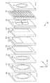
発明者は、プリント回路基板を製造するときに利用されるものに幾つかの特徴において類似するラミネート技術を利用して、低磁場MRIスキャナの(1以上の)磁性コンポーネント(又は1以上の磁性コンポーネントの部分)を加工してよいことを認識した。幾つかの実施態様によれば、低磁場MRIにおける使用のための1以上の磁性コンポーネント(又はそれらの部分)は、1以上の磁性コンポーネント又はそれらの部分を形成するようにパターン化された1以上の非導電性層及び1以上の導電性層を含むラミネートパネルとして提供される。本明細書において、「ラミネート」(“laminate”)という用語は、典型的には、少なくとも1以上の非導電性層及び1以上の導電性層を含む、複数の重ねられた層を指す。独断の断りのない限り、「ラミネート」(“laminate”)という用語は、用いられる材料の種類にとって包括的であり、多数の層を互いに取り付けることを示すが、それらの層を製造するために用いられる如何なる特定の種類の材料又は材料の配置(構成)をも特定しない。「パネル」(“panel”)という用語は、多数のラミネート層のラミネートに由来する構造を概ね記述し、あらゆる形状又は大きさであってよく、任意の数の層を含み得る。 The inventor utilizes a laminating technique that is similar in some aspects to that utilized in manufacturing printed circuit boards to the magnetic component(s) (or magnetic component(s)) of a low field MRI scanner. It was recognized that the part) may be processed. According to some embodiments, the one or more magnetic components (or portions thereof) for use in low field MRI are one or more magnetic components or one or more patterned to form the magnetic components. And a non-conductive layer and one or more conductive layers. As used herein, the term "laminate" refers to a plurality of stacked layers, typically including at least one or more non-conductive layers and one or more conductive layers. Unless otherwise stated, the term “laminate” is inclusive of the type of material used and refers to the attachment of multiple layers to each other, but is not used to make those layers. It does not specify any particular type of material or arrangement of materials (configuration). The term "panel" generally describes a structure resulting from the lamination of multiple laminate layers, which can be of any shape or size and can include any number of layers.
幾つかの実施態様によれば、1以上のB0コイル、1以上の勾配コイル、1以上の送信/受信コイル、及び/又は1以上のシムコイル、或いはそれらの任意の所望の部分又は組み合わせが、単一のラミネートパネルの上に加工されてよく或いは多数のラミネートパネルの間に分散させられてよい。ラミネート技法を利用することは、低磁場MRI磁石を製造する、費用効率的な、調整可能な(scalable)、フレキシブルな、反復可能な、及び/又はカスタマイズ可能なアプローチを促進することがある。更に、発明者は、ラミネート技法を用いて達成可能な精度が、MRIシステムの磁石を製造する或いは生産する従来的な技法を用いることで可能でない、幾何学的構成(geometries)、形態(configurations)及び配置(arrangement)の、設計及び製造を可能にすることを理解した。According to some embodiments, one or more B0 coils, one or more gradient coils, one or more transmit/receive coils, and/or one or more shim coils, or any desired portion or combination thereof, It may be processed on a single laminated panel or dispersed between multiple laminated panels. Utilizing laminating techniques may facilitate a cost-effective, scalable, flexible, repeatable, and/or customizable approach to manufacturing low field MRI magnets. Moreover, the inventor has found that the achievable accuracy using the laminating technique is not possible using conventional techniques of manufacturing or producing magnets for MRI systems, geometries, configurations. It has been understood that it allows for the design and manufacture of arrangements and arrangements.
後続は、低磁場MRIを含む低磁場磁気共鳴用途のための方法及び装置に関する様々な着想及びそれらの実施態様の、より詳細な記述である。本明細書中に記載する様々な特徴は、数多くの方法のうちのいずれかにおいて実施されてよいことが理解されるべきである。具体的な実施の実施例は、本明細書中に例示的な目的だけのために提供される。加えて、実施態様中に記載される様々な特徴は、単独で或いはあらゆる組み合わせにおいて用いられてよく、本明細書中に明示的に記載される組み合わせに限定されない。 The following is a more detailed description of various ideas and embodiments of methods and apparatus for low field magnetic resonance applications, including low field MRI. It should be appreciated that the various features described herein may be implemented in any of numerous ways. Examples of specific implementations are provided herein for illustrative purposes only. In addition, the various features described in the embodiments may be used alone or in any combination and are not limited to the combinations explicitly described herein.
上で議論したように、発明者は、低磁場MRIシステムは、高磁場MRIシステムと関連付けられる問題のうちの1以上に対処する、低磁場MRIシステムを開発した。例えば、例示的な低磁場MRIシステムは、超伝導磁石を用いずに実施されてよく、結果的に、関連付けられる低温冷却システムを用いずに実施されてよく、それにより、結果として得られるMRIシステムのコスト、複雑さ、及び大きさを有意に減少させることがある。高磁場MRIに適した磁場強度及び磁場同質性を有するB0磁場を生成するために、超伝導材料で形成されるソレノイドコイルが用いられ、生成されるB0磁場は、ソレノイドの中心を通じる軸の方向にある。結果的に、患者を撮像することは、ソレノイドコイルの内側に患者を配置することを含む。ソレノイドコイルは、高い磁場強度で同質な磁場を生成するのに特に適しているが、この幾何学的構成は、機器の大きさを増大させるのみならず、患者が撮像されるべき円筒形ボア内に挿入されることも必要とする。よって、この幾何学的構成は、閉所恐怖症の患者に適さないことがあり、大きな患者を収容し得ないことがある。よって、高磁場MRIのために適したB0磁石を生成するのに一般的に必要とされるソレノイドコイル幾何学的構成は、高磁場MRIが実際的且つ利用可能な汎用イメージャであるのを妨げる更なる制約を有する。As discussed above, the inventor has developed a low field MRI system that addresses one or more of the problems associated with high field MRI systems. For example, the exemplary low field MRI system may be implemented without a superconducting magnet and, consequently, without an associated cryogenic cooling system, thereby resulting in an MRI system. May significantly reduce the cost, complexity, and size of the. A solenoid coil formed of a superconducting material is used to generate a B0 magnetic field having a magnetic field strength and magnetic field homogeneity suitable for high magnetic field MRI, and the generated B0 magnetic field is an axis passing through the center of the solenoid. In the direction of. Consequently, imaging the patient includes positioning the patient inside the solenoid coil. Although the solenoid coil is particularly suitable for producing a homogeneous magnetic field with high magnetic field strength, this geometry not only increases the size of the device, but also the cylindrical bore within which the patient is to be imaged. Need to be inserted into. Thus, this geometry may not be suitable for claustrophobic patients and may not be able to accommodate large patients. Thus, the solenoid coil geometry typically required to produce a B0 magnet suitable for high field MRI prevents high field MRI from being a practical and available general purpose imager. It has additional constraints.
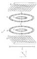
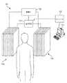
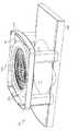
発明者は、低磁場MRIの特性が、高磁場MRIに適さない代替的なコイル幾何学的構成を用いて低磁場MRIに適したB0磁場を生成するのを可能にすることを理解した。図1は、幾つかの実施態様に従った、低磁場MRI映像法に適したB0磁場を生成するために利用されてよい2平面磁石幾何学的構成を含む低磁場MRIシステム100の部分を図式的に例示している。2平面電磁石は、2つの外側コイル110a及び110bと、2つの内側コイル112a及び112bとを含む。適切な電流がコイルに適用されると、矢印によって示される方向において磁場が生成されて、コイルの間に視野を有するB0磁場を生成し、B0磁場は、適切に設計され且つ構築されるとき、低磁場MRIに適することがある。The inventor has realized that the properties of low field MRI make it possible to generate a B0 field suitable for low field MRI using an alternative coil geometry that is not suitable for high field MRI. FIG. 1 illustrates a portion of a low
図1に例示される2平面幾何学的構成は、高磁場MRIのための十分な同質性のB0磁場を得ることの困難性の故に、高磁場MRIに概して適さないことが理解されるべきである。図1に例示される2平面B0磁石は、概ね開放型の幾何学的構成をもたらし、従来的な高磁場ソレノイドコイル幾何学的構成で撮像されるのを拒絶することがある恐怖症を患う患者でのその使用を促進する。更に、2平面設計は、その開放型の設計、幾つかの場合には、低磁場強度及び同質性で可能な概ねより大きい視野の結果、より大きな患者でのその使用も促進することがある。It should be understood that the two-plane geometry illustrated in FIG. 1 is generally unsuitable for high field MRI due to the difficulty of obtaining a sufficiently homogeneous B0 field for high field MRI. Is. The bi-planar B0 magnet illustrated in FIG. 1 results in a generally open geometry and suffers from phobia that may refuse to be imaged with conventional high field solenoid coil geometry. Promotes its use in patients. In addition, the biplanar design may also facilitate its use in larger patients as a result of its open design, and in some cases low field strength and the generally larger field of view possible with homogeneity.
しかしながら、図1に例示する2平面B0磁石は、高磁場MRIのために可能であるものよりもずっと複雑でなく低コストのB0磁石をもたらすのに対し、コイル110a,110b,112a,112bの生産は、典型的には、所与のセットのコイルのための特定の設計に従った多数の巻き(turn)をもたらすために、支持フレームの周りの銅ワイヤの反復的な巻回を概して含む、比較的時間がかかる繊細なプロセスである。低磁場MRIのための適切なB0磁場をもたらすために、概ね高品質の導体(例えば、ハイグレードな絶縁を備える厚い銅ワイヤ)をしばしば用いて、所望のB0磁場を生成するために必要とされる比較的大きな電流をサポートする。導体の各巻きを精密に且つ適切に整列させて巻回して所望の同質性を有するB0磁場を生成することが配慮されなければならない。図1に示すように、2平面磁石における外側コイルの例示的な直径は220cmであってよく、巻きの典型的な数は50巻き以上のオーダであり、それにより、多数の巻きに亘って整列して精密に巻回されなければならない相当な量の導体材料(例えば、2平面磁石の各側について1キロメートルよりも長い概ねハイグレードのワイヤ)を必要とする。However, the bi-planar B0 magnet illustrated in FIG. 1 results in a B0 magnet that is much less complex and less costly than is possible for high field MRI, whereas
加えて、ペア(例えば、コイル110a,110b及びコイル112a,112b)における各コイルは、コイルがひとたび通電された後に結果として得られるB0磁場の同質性を劣化させるのを避けるために、そのペア内の対応するコイルと実質的に同一であるように製造されなければならない。その上、2平面磁石の各側にあるコイル(例えば、コイル110a,110b及びコイル112a,112b)も、結果として得られるB0磁場の異質性を減少させるよう、注意深く位置付けられ且つ整列させられなければならない。従って、従来的な構築技術を用いて低磁場MRIのための十分に同質なB0をもたらすために、そのようなコイルを製造し且つ据え付けることは、比較的費用がかかりがちであり、時間集約的でありがちであり、間違いが起こりがちである。In addition, each coil in the pair (eg, coils 110a, 110b and
上で議論したように、発明者は、上述の従来的な製造技法の代わりに(又はそれとの組み合わせにおいて)ラミネート技法を利用して、低磁場MRIにおける使用のためのB0磁場又はその部分を加工してよいことを認識した。具体的には、発明者は、B0磁性コンポーネントの低磁場特性が、MRIのためのB0磁場を生成するために以前は利用可能でなかった技法を用いて、B0磁性コンポーネント又はその部分の加工を可能にすることを理解し且つ察知した。例えば、数ある理由の中でも、発明者は、低磁場MRIのより低い電力要求及び/又は熱出力の減少が、高磁場の脈絡において利用可能でなかったラミネート技法を用いて磁性コンポーネントの生産を可能にすることを理解した。As discussed above, the inventor utilizes a laminating technique in place of (or in combination with) the conventional manufacturing techniques described above to provide a B0 field or portion thereof for use in low field MRI. I realized that I could process it. Specifically, the inventor has found that the low magnetic field properties of B0 magnetic components use techniques previously not available to generate B0 magnetic fields for MRI to allow B0 magnetic components or parts thereof. I understood and made it possible to process For example, the inventor, among other reasons, enables the production of magnetic components using laminating techniques where the lower power requirements and/or reduced heat output of low field MRI were not available in high field contexts. I understand that.
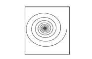
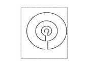
幾つかの実施態様によれば、ラミネートパネルは、低磁場MRIに適したB0磁場を生成し得る或いは低磁場MRIに適したB0磁場に寄与し得る1以上のB0コイル又は1以上のB0コイルの部分を形成するようにパターン化された少なくとも1つの導電性層を含む。本明細書中で用いられるとき、B0コイルは、B0磁場をもたらす或いはB0磁場に寄与するあらゆるコイルを指し、1以上の主B0コイル又はその部分、1以上のシムコイル又はその部分、或いは1以上の矯正コイル又はその部分等を含んでよい。According to some embodiments, the laminate panels, one or more that may contribute to the B0 field suitable for B0 or a low field MRI can generate a magnetic field suitable for low field MRI B0 coil or one or more It includes at least one conductive layer patterned to form part of a B0 coil. As used herein, B0 coil, B0 refers to any coil leads or contributes to the B0 field and magnetic field, one or more primary B0 coil or part thereof, one or more shim coils, or portions thereof, Alternatively, it may include one or more orthodontic coils or parts thereof.
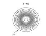
ラミネートパネル(laminate panel)は、図1に例示される2平面B0コイルのペアの1つの「側」(“side”)を形成する複数の同心状のコイルを含んでよい。第2のラミネートパネルが、2平面設計における視野の他の「側」のためのB0コイルを含むよう同様に構成されてよい。このようにして、低磁場MRIのためのB0磁場を生成するために用いられる磁性コンポーネントが、ラミネートパネル技法を用いて構築されてよい。A laminate panel may include a plurality of concentric coils forming one "side" of a pair of biplanar B0 coils illustrated in FIG. The second laminate panel may be similarly configured to include the B0 coil for the other “side” of the field of view in the biplanar design. In this way, the magnetic components used to generate the B0 field for low field MRI may be constructed using laminated panel techniques.
以下に更に詳細に議論するように、1以上のB0コイル(又はその部分)を加工するためにラミネート技法を用いることは、低磁場MRIにおける使用のためのB0磁場を製造することにおいて上で議論した欠点のうちの1以上に対処し得る。例えば、B0磁場同質性は、それぞれのコイルのパラメータの比較的小さな変化に対して極めて敏感である。具体的には、様々なコイルのコイル巻線、位置、及び整列等の変動は、生成されるB0磁場の磁場異質性を引き起こす。結果的に、概ね反復可能で低コストのプロセスにおいて低磁場MRIを行うのに適した磁場同質性を備えるB0磁場を生成し得るB0磁石を生成するのは困難なことがある。具体的には、そのようなB0磁石を再現するのは困難なことがある。何故ならば、従来的な製造技法は、再現可能で確実な生産に役立たず、従って、十分に増減せず、数多くの成功裡のB0磁石を時間効率的及び/又は費用効率的な方法において生産する能力を制限する。ラミネート技法は、従来的な技法を用いて実現可能であるものよりも、磁性コンポーネントをより一層精密に且つ正確に生産することができ、以下に更に詳細に議論するように、磁性コンポーネントを生産するための大いに調整可能な技法である。As will be discussed in more detail below, using a laminating technique to fabricate one or more B0 coils (or portions thereof) can be useful in producing B0 magnetic fields for use in low field MRI. One or more of the deficiencies discussed in can be addressed. For example, the B0 field homogeneity is extremely sensitive to relatively small changes in the parameters of each coil. Specifically, variations in coil windings, position, alignment, etc. of the various coils cause magnetic field heterogeneity of the generated B0 magnetic field. As a result, it can be difficult to generate a B0 magnet that can generate a B0 magnetic field with suitable magnetic field homogeneity for low field MRI in a generally repeatable, low cost process. Specifically, reproducing such a B0 magnet can be difficult. Because conventional manufacturing techniques do not lend themselves to reproducible and reliable production, and therefore do not scale well, and a large number of successful B0 magnets in a time and/or cost effective manner. Limit the ability to produce. Lamination techniques can produce magnetic components with greater precision and accuracy than are achievable using conventional techniques, and produce magnetic components, as discussed in more detail below. It is a highly adjustable technique for.
図1は、例示の低磁場MRIの部分についての位相及び周波数符号化を促進するよう磁場を生成する、一対の平面的な勾配コイルセット120a,120bも図式的に例示している。上で議論したように、MRIシステムは、受信するMR信号の空間的な場所を周波数又は位相の関数として符号化するよう、勾配コイルを用いて既知の方法においてB0磁場を系統的に変更することによって、受信するMR信号を符号化する。例えば、勾配コイルは、特定の方向に沿う空間的な場所の線形関数として周波数又は位相を変更するように構成されてよいが、非線形勾配コイルを用いることによって、より複雑な空間符号化プロファイルが提供されてもよい。例えば、第1の勾配コイルが、第1の(X)方向においてB0磁場を選択的に変更して、その方向において周波数符号化を行うように構成されてよく、第2の勾配コイルが、第1の方向に対して実質的に直交する第2の(Y)方向においてB0磁場を選択的に変更して、位相符号化を行うように構成されてよく、第3の勾配コイルが、第1及び第2の方向に対して実質的に直交する第3の(Z)方向においてB0磁場を変更して、容量撮像用途のためのスライス選択を可能にするように構成されてよい。FIG. 1 also schematically illustrates a pair of planar
勾配コイルは、特定のB0磁性コンポーネント(例えば、図1に示されるような1以上のB0コイル)と協働するように設計され、そして、満足に動作するように、典型的には、比較的精密な及びB0磁性コンポーネントとの引き続きの整列を必要とするように設計される。発明者は、ラミネート技術を用いて1以上の勾配コイル(又はそれらの部分)を加工することは、低磁場MRIシステムの磁性コンポーネントを製造するより単純でより費用効率的なアプローチを促進することがあることを認識した。Gradient coils are designed to work with a particular B0 magnetic component (eg, one or more B0 coils as shown in FIG. 1) and typically operate in a satisfactory manner. It is designed to require relatively precise and subsequent alignment with the B0 magnetic component. The inventor has discovered that processing one or more gradient coils (or portions thereof) using laminating techniques can facilitate a simpler and more cost-effective approach to manufacturing magnetic components of low field MRI systems. I realized that there is.
幾つかの実施態様によれば、ラミネートパネルは、低磁場MRI装置内で作動させられるときに、検出されるMR信号の空間的な符号化をもたらすのに適した磁場を生成し得る或いはそのような磁場に寄与し得る、1以上の勾配コイルを形成するようにパターン化される少なくとも1つの導電層又は1以上の勾配コイルの部分を含む。例えば、ラミネートパネルは、1以上のX勾配コイル(又はそれらの部分)、1以上のY勾配コイル(又はそれらの部分)、及び/又は1以上のZ勾配コイル(又はそれらの部分)を形成するようにパターン化される、1以上の導電層を含んでよい。1以上の勾配コイル(又はそれらの部分)を形成するラミネートパネルは、対応するB0磁性コンポーネントと別個であってよく、或いは同じラミネートパネルの1以上の層内に形成されてよい。後者に関して、1以上のコイルは、1以上のB0コイル(又はそれらの部分)と共有される(しかしながら、電気的に絶縁される)導電層によって形成されてよく、或いは1以上のB0コイル(又はそれらの部分)と別個の1以上の導電層内に形成されてよい。ラミネートパネル内の1以上のB0コイル(又はそれらの部分)との1以上の勾配コイル(又はそれらの部分)の統合は、低磁場MRIのための磁性コンポーネントを設計し且つ製造するより単純でより柔軟なアプローチを促進し、それらの更なる特徴を以下に議論する。According to some embodiments, the laminated panel may generate a magnetic field suitable for effecting spatial encoding of the detected MR signal when operated in a low field MRI apparatus, or such. Of at least one conductive layer or portions of one or more gradient coils that are patterned to form one or more gradient coils that can contribute to different magnetic fields. For example, a laminated panel forms one or more X gradient coils (or portions thereof), one or more Y gradient coils (or portions thereof), and/or one or more Z gradient coils (or portions thereof). May include one or more conductive layers that are patterned. The laminate panel forming one or more gradient coils (or portions thereof) may be separate from the corresponding B0 magnetic component or may be formed in one or more layers of the same laminate panel. With respect to the latter, the one or more coils may be formed by a conductive layer shared (but electrically isolated) with the one or moreB0 coils (or portions thereof), or the one or moreB0 coils. (Or portions thereof) may be formed in one or more conductive layers separate. Integrating one or more gradient coils (or parts thereof) with one or more B0 coils (or parts thereof) in a laminated panel is simpler than designing and manufacturing magnetic components for low field MRI. Facilitating a more flexible approach, their further characteristics are discussed below.
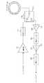
上で議論したように、MRIシステムは、(無線周波数(RF)コイルと呼ばれる)送信及び受信コイルをそれぞれ用いて、発せられるMR信号を刺激し且つ検出する。送信/受信コイルの形態は、実施と共に異なり、送信及び受信のための単一のコイル、送信及び受信のための別個のコイル、送信及び/又は受信のための多数のコイル、或いは単一チャネル(single channel)又は平行MRI(parallel MRI)における使用システムを達成する任意の組み合わせを含んでよい。よって、RMIシステムの送信及び受信コンポーネントのための様々な形態を一般的に指すために、送信/受信磁石コンポーネントを、しばしば、Tx/Rx又はTx/Rxコイルと呼ぶ。 As discussed above, MRI systems use transmit and receive coils (referred to as radio frequency (RF) coils), respectively, to stimulate and detect the MR signals emitted. The form of the transmit/receive coil will vary depending on the implementation: a single coil for transmit and receive, separate coils for transmit and receive, multiple coils for transmit and/or receive, or a single channel ( It may include any combination that achieves a system of use in single channel or parallel MRI. As such, the transmit/receive magnet components are often referred to as Tx/Rx or Tx/Rx coils to generically refer to the various configurations for the transmit and receive components of an RMI system.
発明者は、ラミネート技法を用いて低磁場MRIシステムにおける1以上の送信/受信コイルを加工してもよいことを認識した。幾つかの実施態様によれば、ラミネートパネルは、受信するMR信号を空間的に符号化するためにB0磁場及び/又は対応する勾配磁場を生成するように構成される磁性コンポーネントと共に作動させられるときに、B1励起場を生成すること(送信)によって並びに/或いは発せられるMR信号を受信すること(受信)によってMR応答を刺激するように構成される、1以上の送信及び/又は受信コイル或いは1以上の送信及び/又は受信コイルの部分を形成するようにパターン化された少なくとも1つの導電性層を含む。そのようなラミネートパネルは、単一チャネル又は平行MRIをそれぞれ遂行するために単一の送信及び/又は受信コイル(又はそれらの部分)或いは多数の送信及び/又は受信コイル(又はそれらの部分)を含んでよく、以下に更に詳細に議論するように、別個のラミネートパネル内に形成されてよく或いは1以上のB0コイル(又はその部分)及び/又は1以上の勾配コイル(又はそれらの部分)を含むラミネートパネル内に統合されてよい。The inventor has recognized that laminating techniques may be used to fabricate one or more transmit/receive coils in a low field MRI system. According to some embodiments, the laminate panel is operated with a magnetic component configured to generate a B0 magnetic field and/or a corresponding gradient magnetic field to spatially encode the received MR signal. Occasionally, one or more transmit and/or receive coils configured to stimulate the MR response by generating a B1 excitation field (transmission) and/or receiving an emitted MR signal (reception) Alternatively, it comprises at least one electrically conductive layer patterned to form part of one or more transmit and/or receive coils. Such laminated panels may have a single transmit and/or receive coil (or part thereof) or multiple transmit and/or receive coils (or parts thereof) to perform single channel or parallel MRI, respectively. May be included and may be formed in a separate laminate panel, or one or more B0 coils (or portions thereof) and/or one or more gradient coils (or portions thereof), as discussed in more detail below. May be integrated into a laminated panel including.
低磁場MRIシステムは、システムを支援して磁場を生成するよう配置される1以上のシムコイル(shim coils)のような追加的な磁性コンポーネントを更に含んで、例えば、B0磁場の強度及び/又は同質性を増大させ、勾配コイルの作動によって創り出されるような有害な磁場効果(field effects)、撮像される物体の装荷効果(loading effects)を相殺し、或いは低磁場MRIシステムの磁気学をその他の方法で支援してよい。シムコイルを作動させてMRIシステムのB0磁場に寄与する(例えば、磁場強度に寄与し且つ/或いは同質性を向上させる)とき、シムコイルはシステムのB0コイルとして機能し、そのように理解されるべきである。幾つかの実施において、1以上のシムコイルは、以下に更に詳細に議論するように、他のB0コイルと独立して作動させられてよい。The low field MRI system further includes additional magnetic components, such as one or more shim coils arranged to assist the system to generate the magnetic field, eg, the strength of the B0 magnetic field and/or It increases homogeneity, cancels out detrimental field effects, such as those created by actuation of gradient coils, loading effects of the imaged object, or otherwise reduces the magnetics of low field MRI systems. You may assist in ways. When a shim coil is activated to contribute to the B0 field of an MRI system (eg, contributes to magnetic field strength and/or enhances homogeneity), the shim coil functions as the system's B0 coil and is understood as such. Should be. In some implementations, one or more shim coils may be operated independently of other B0 coils, as discussed in more detail below.
更に、低磁場MRIシステムは、環境内の並びに/或いはコンポーネント間の望まれない電磁放射線を抑制するよう配置される(複数の)遮蔽コンポーネントを更に含んでよい。発明者は、ラミネート技術を利用して、そのようなコンポーネントを別個の(複数の)ラミネートパネル内で形成することによって、或いは、そのようなコンポーネントを、以下に更に詳細に議論するように、低磁場MRIシステムの他の磁性コンポーネント(若しくはそれらの部分)のうちのいずれか1つ又は組み合わせを含むラミネートパネル内に統合することによって、そのようなコンポーネント、例えば、1以上のシムコイル(若しくはそれらの部分)及び/又は1以上の遮蔽コンポーネントを加工してよいことを認識した。 In addition, the low field MRI system may further include shielding component(s) arranged to suppress unwanted electromagnetic radiation in the environment and/or between the components. The inventor utilizes laminating techniques to form such components in separate (plural) laminate panels, or such components can be manufactured at low cost, as discussed in more detail below. Such components, eg, one or more shim coils (or portions thereof) by integration in a laminate panel that includes any one or combination of other magnetic components (or portions thereof) of a magnetic field MRI system. ) And/or one or more shielding components may be processed.
上で議論したように、低磁場MRIシステムの1以上の磁性コンポーネントを含む、パネル、プレート又は「ボード」を生産するためのラミネート技法は、原理的には、スケール(scale)、電力及び熱要件等において異なるが、プリント回路基板(PCB)及び特定の限定的なプリント電子機器を加工するために従来的に用いられる技法に似てよい。そのようなラミネート技法は、非導電層及び導電層の材料を形成すること並びに(例えば、材料を選択的に除去し且つ/或いは追加することによって)導電性及び非導電性の(複数の)層をパターン化して所望の導電パターン又は「回路」(“circuit”)を生成することを概ね含む。そのような技法は、例えば、PCBの表面に取り付けられる別個のコンポーネントの間の電気的な相互接続をもたらすよう、単層及び多層のPCBsを生産するために従来的に用いられ、限定的な程度まで特定の電子コンポーネントを生産するためにも用いられている。 As discussed above, laminating techniques for producing panels, plates or "boards" that include one or more magnetic components of a low field MRI system are, in principle, scale, power and thermal requirements. Etc., but may resemble techniques conventionally used to fabricate printed circuit boards (PCBs) and certain limited printed electronics. Such laminating techniques include forming materials for the non-conductive and conductive layers, as well as conductive and non-conductive layer(s) (eg, by selectively removing and/or adding material). Generally to produce a desired conductive pattern or "circuit". Such techniques are conventionally used to produce single-layer and multi-layer PCBs, for example, to provide electrical interconnection between discrete components mounted on the surface of a PCB, to a limited extent. It is also used to produce specific electronic components up to.
上で議論したように、高磁場MRIシステムの高い磁場強度、有意な電力要求、複雑な低温冷却システム等の故に、ラミネート技法は、高磁場の脈絡において実行可能な解決策を提示せず、MRIのための磁性コンポーネントを生産することにおける使用について以前に想定されていなかった。しかしながら、発明者は、低磁場の脈絡において、ラミネート技法を用いて低磁場MRIシステムの1以上の磁性コンポーネントを加工してよいことを認識した。その実施例を以下に更に詳細に議論する。 As discussed above, due to the high magnetic field strength, significant power requirements, complex low temperature cooling systems of high field MRI systems, the laminating technique does not present a viable solution in the context of high field MRI and Had not previously been envisioned for use in producing magnetic components for. However, the inventor has recognized that in a low field context, laminating techniques may be used to fabricate one or more magnetic components of a low field MRI system. Examples of which are discussed in further detail below.
上でも議論したように、従来的な技法(例えば、1以上の巻回コイル)を用いてB0磁石を生産することは、時間のかかるプロセスであり得るし、製造偏差等の故に、整列誤差及び/又は異質性の影響を受けることがある。しかしながら、発明者は、磁性コンポーネントを生産するためのそのような従来的な技術が、本明細書中に記載するラミネート技法と共に有利に用いられてよいことを理解した。例えば、従来的な技法を用いて製造される1以上のB0コイルは、ラミネート技法を用いて加工される1以上のB0コイルで補完されてよい。「混成」磁石の幾つかの実施例を以下に更に詳細に議論する。As discussed above, producing B0 magnets using conventional techniques (eg, one or more wound coils) can be a time consuming process, and due to manufacturing deviations and the like, alignment errors can occur. And/or may be affected by heterogeneity. However, the inventor has realized that such conventional techniques for producing magnetic components may be advantageously used with the laminating techniques described herein. For example, one or more B0 coil made using conventional techniques may be complemented by one or more B0 coils to be processed using lamination techniques. Some examples of "hybrid" magnets are discussed in more detail below.
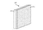
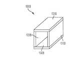
図2Aは、単一の非導電層210と、非導電層の上に形成される単一の導電層212とを含む、ラミネートパネル200を概略的に例示している。(ここでは基板とも呼ぶ)非導電層210は、任意の適切な材料から形成されてよい。例えば、適切なコア材料の任意の1つ又は組み合わせで基板210を形成してよく、複合材、接着剤、及び/又はラミネートを利用して、非導電層を形成し、ラミネートパネルを生産するのを促進してよく、FR4、セラミック、プラスチック、ガラス、ポリイミド、エポキシ、事前含浸複合繊維(プリプレグ)、92MLのような多機能エポキシラミネート、又は適切な特性を有する任意の他の(複数の)材料若しくはそれらの組み合わせを含むが、それらに限定されない。基板210は単層であってよく、或いは非導電性材料の多層で構成されてよく、それらの各層は、同じ又は異なる非導電性材料で作製されてよい。基板を層状化することは、異なる材料の有益な特性を利用する基板の構築を可能にすることがある。基板210は、所与の設計に適した長さ、幅、及び厚さを有する、任意の所望の寸法に構成されてよい。 FIG. 2A schematically illustrates a
同様に、導電層212は、任意の適切な導電性材料で形成されてよい。例えば、導電層212は、銅又は他の適切な導電性材料の薄い又は厚い膜、厚い又は極めて厚い導電層(例えば、「エキストリーム銅」(“extreme copper”))、導電性プレート、或いは任意の適切な技法又はプロセスによって(例えば、浸漬被覆、電気めっき、印刷、モールディング、ボンディング、真空含浸、押圧、乾式接着、又は任意の他の適切な(複数の)技法を介して)非導電性基板210の上にラミネートとして形成され得る任意の他の種類の導電層であってよい。幾つかの実施態様によれば、以下に更に詳細に議論するように、アルミニウムが導体として用いて、関連付けられるコスト及び重量の削減を活用してよい。 Similarly,
所望の「回路構成」(“circuitry”)をもたらすために、様々な減法(subtractive)、加法(additive)、及び/又は半加法(semi-additive)プロセスのうちの任意の1つ又は組み合わせを用いて、(複数の)導電層212をパターン化させて、低磁場MRI装置の1以上の磁性コンポーネントの所望の部分のための導電体を形成してよい。減法プロセスは、例えば、非限定的に、化学エッチング、写真凸版等を含む、様々なリソグラフィプロセスのいずれかを用いて、導電層から導電性材料(例えば、銅)を選択的に除去して、所望の導電性パターンを残して、所望の導電性回路又は回路の部分をもたらす。そのようなプロセスは、(しばしばマスクと呼ばれる)所望のパターンにおいてレジスト材料を提供し、導電層を対応するエッチング液に導いて、レジスト材料で処理されていない場所にある導電性材料を除去することによって、行われる。他の減法プロセスは、導電層の望ましくない部分を切削して、所望の導電性パターンを残すことを含む。本明細書中に記載する減法プロセス及び/又は任意の他の適切なプロセスを単独で或いは任意の組み合わせにおいて用いて、所望の導電性パターンを加工してよい。 Using any one or combination of various subtractive, additive, and/or semi-additive processes to provide the desired "circuitry". And the conductive layer(s) 212 may be patterned to form conductors for desired portions of one or more magnetic components of a low field MRI device. The subtractive process selectively removes the conductive material (eg, copper) from the conductive layer using any of a variety of lithographic processes including, but not limited to, chemical etching, photolithography, etc., The desired conductive pattern is left behind, leaving the desired conductive pattern. Such a process provides a resist material in a desired pattern (often called a mask) and directs the conductive layer into a corresponding etchant to remove the conductive material in places not treated with the resist material. Done by Another subtractive process involves cutting unwanted portions of the conductive layer to leave the desired conductive pattern. The subtractive process described herein and/or any other suitable process may be used alone or in any combination to fabricate the desired conductive pattern.
加法プロセスは、基板の上に所望の導電性パターンを電気めっきすること又は導電性インクを用いてパターンを印刷すること(“printing”)を含んでよい。例えば、電気めっきは、所望のパターンにおいてマスキングされた感光膜を露出させることを含んでよい。次に、露出させられたパターンは、化学浴(chemical bath)に導入されて、パターンが金属イオン結合し得るのを可能にし、次に、導体で(例えば、銅で)めっきされてよく、導体は化学浴内で感光性を与えられた(sensitized)パターンと結合して、所望の導電性パターンを形成する。加法プロセスは、所望の導電性パターンを形成するために、減法技法よりも少ない導電性材料を必要とするという利点を有する。他のプロセスは、減法技法及び加法技法の両方を組み合わせて、所望の導電性パターンを形成する。 The additive process may include electroplating the desired conductive pattern on the substrate or "printing" the pattern with a conductive ink. For example, electroplating may include exposing the masked photoresist in a desired pattern. The exposed pattern may then be introduced into a chemical bath to allow the pattern to metal ion bond and then be plated with a conductor (eg, with copper). Combine with the sensitized pattern in the chemical bath to form the desired conductive pattern. The additive process has the advantage of requiring less conductive material than the subtractive technique to form the desired conductive pattern. Other processes combine both subtractive and additive techniques to form the desired conductive pattern.
幾つかの実施態様によれば、ラミネート技法を用いて加工される1以上の磁性コンポーネントは、「ヘビー銅」(“heavy copper”)(例えば、5oz/ft2〜19oz/ft2)又は「エキストリーム銅」(“extreme copper”)(例えば、20oz/ft2〜200oz/ft2)としばしば呼ばれる、比較的大きな厚さで加工されるのを必要とすることがあるが、技法は導電性材料の選択に拘わらず当て嵌まる。ヘビー銅又はエキストリーム銅をパターン化する適切な技法の実施例は、塩化第二銅エッチング、塩化第二鉄エッチング、機械研削、プラズマエッチング、レーザエッチング、放電加工(EDM)、めっき等のいずれか1つ又は組み合わせを含むが、これらに限定されない。本明細書中に記載する任意の単一の技法又は技法の組み合わせが利用されてよく或いは非導電性基板の上に導電層をパターン化するのに適した及び/又はラミネートパネルを生産するのに適した任意の他の技法が用いられてよいことが理解されるべきである。何故ならば、ラミネートパネル内に低磁場MRIシステムの1以上の磁性コンポーネント(又はそれらの部分)を形成することの特徴は、それを行うための如何なる特定の技法又は技法の組み合わせにも限定されないからである。According to some embodiments, one or more magnetic components that are processed using lamination techniques, "heavy copper" ( "heavy copper")(e.g., 5oz / ft 2 ~19oz / ft 2) or "equi stream copper "(" extreme copper ")(e.g., 20oz / ft 2 ~200oz / ft 2) and is often referred to, but may require being processed a relatively large thickness, technique conductive material It applies regardless of your choice. Examples of suitable techniques for patterning heavy copper or extreme copper are any of cupric chloride etching, ferric chloride etching, mechanical grinding, plasma etching, laser etching, electrical discharge machining (EDM), plating, etc. Including but not limited to one or a combination. Any single technique or combination of techniques described herein may be utilized or suitable for patterning conductive layers on non-conductive substrates and/or for producing laminated panels. It should be appreciated that any other suitable technique may be used. Because, the features of forming one or more magnetic components (or portions thereof) of a low field MRI system in a laminated panel are not limited to any particular technique or combination of techniques for doing so. Is.
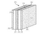
図2Bは、複数の非導電層210と、非導電層の間に形成される複数の導電層212とを含む、ラミネートパネル205を概略的に例示している。導電層212の間の接続は、以下により詳細に記載するように、「ビア」(“vias”)と呼ばれる介在する非導電層内に導電性材料で充填された穴(例えば、めっきされた貫通穴)を形成することによって達成されてよい。2つの非導電性及び2つの導電層のみが図2Bに明示的に例示されているが、楕円によって示されるように、任意の数の非導電層及び導電層を用いて所望の設計に従ったラミネートを達成してよく、それらの幾つかの実施例を以下に更に詳細に記載する。 FIG. 2B schematically illustrates a
加えて、各非導電層について多数の導電層が設けられてよい、例えば、両側に積層された(laminated)導電層を有する非導電層が設けられてよいことが理解されるべきである。図2Cは、2つのラミネート層を互いに取り付けることによって形成される多層パネルを例示しており、各々のパネルは、非導電層210を有し、導電層がそれぞれの非導電層の両側に積層されている。多層ラミネートは、1以上の接着層214を用いて取り付けられてよい。(複数の)接着層214は、任意の適切な接着剤、又はプリプレグ、乾式接着剤、エポキシのような、材料の組み合わせであってよく、且つ/或いは、(例えば、熱及び/又は圧力を介して)アクティブ化させられるときに、多層ラミネートを互いに結合させる任意の他の層又は層の組み合わせであってよい。ラミネート技法のいずれか1つ又は組み合わせを用いる、導電性及び非導電性の層状化、接着剤等の任意の構成を用いて、所望のラミネートパネルを生産してよいことが理解されなければならない。 In addition, it should be understood that multiple conductive layers may be provided for each non-conductive layer, eg, non-conductive layers with laminated conductive layers on both sides. FIG. 2C illustrates a multi-layer panel formed by attaching two laminate layers to each other, each panel having a
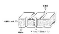
上で議論したように、ラミネートパネルの層は、ラミネートパネル内の適切な層を通じて形成されるビアの所望の配置を用いて電気的に接続されてよい。図3Aは、例示的なラミネート層の部分の断面図を例示しており、ラミネート層の上には、非導電性材料325上に銅導体250をパターン化することによって、導電性トレースが形成され、導電性トレースは層間のビアを用いて接続される。銅導体350は、任意の所望の幾何学的構成においてパターン化されてよく、そして、低磁場MRIシステムの1以上の磁性コンポーネント(又はその部分)及び/又は任意のサポート電子機器、制御電子機器等に対応する所望の回路構成を形成するように構成されてよい。異なる層の上の銅導体は、めっきされた貫通穴ビア355のようなビアを用いて、電気的に接続されてよい。めっきされた貫通穴は、ラミネートパネルの1以上の層を通じて穴を穿孔することによって、並びに、非導電性材料を通じる導電性経路を形成して異なる層の上の電気導体を接続する適切なめっき技法を用いることによって、形成されてよい。ビアはラミネートパネル全体を通じて形成されてよく、或いはラミネートパネルの層のサブセットを通じて形成されてよく、隣接する層又は多数の隣接する層を接続することを含むことが理解されるべきである。ラミネートパネルのラミネート層が、ラミネートパネルの異なる層を接続するよう配置される多数のビアを含んでよい。例えば、多数のコンポーネント又は多数のコンポーネントの部分を有する層を互いに電気的に絶縁させ、必要に応じて、他の層の上にパターン化される導体に独立的に接続してよい。ラミネートパネルの層の上にパターン化される導体は、任意の所望の方法において接続されてよく、1以上の層はビアを全く含まなくてよく、従って、ラミネートパネルの他の層から電気的に絶縁されたままである。 As discussed above, the layers of the laminate panel may be electrically connected with the desired placement of vias formed through the appropriate layers in the laminate panel. FIG. 3A illustrates a cross-sectional view of a portion of an exemplary laminate layer on which conductive traces are formed by patterning copper conductors 250 on a non-conductive material 325. , The conductive traces are connected using vias between layers.
発明者は、銅がそれを電気導体にとっての魅力的な選択肢とする特性を有するが、アルミニウムを代替として或いは銅のような他の導体との組み合わせにおいて用いて、ラミネートパネルの層の上に1以上の磁性コンポーネント(又はその部分)をパターン化してもよいことを理解した。アルミニウムは、銅よりも重量が少なく、より安価であり、よって、幾つかの実施態様によれば、より軽量で減少させられたコストのラミネートパネルを加工する能力を促進する。図3Bは、アルミニウム導体370を用いて導電性パターンが形成されるラミネート層の部分の断面を例示している。アルミニウム導体370は、本明細書中に記載する同じラミネート技法を用いて形成されてよい。アルミニウムは、銅と比べてより低い導電性を有するので、アルミニウム導体370は、一般的に、同じ導電性を得るために銅導電体350よりもより大きい厚さで形成される必要がある(例えば、類似の性能を達成するために、50milの銅の代わりに、80milのアルミニウム層が必要とされることがある)。 The inventor has found that copper has the property that it makes it an attractive choice for electrical conductors, but aluminum is used as an alternative or in combination with other conductors such as copper to provide a layer on a layer of a laminated panel. It is understood that the above magnetic components (or portions thereof) may be patterned. Aluminum weighs less and is less expensive than copper, and thus, according to some embodiments, facilitates the ability to process lighter, reduced cost laminated panels. FIG. 3B illustrates a cross section of a portion of the laminate layer where the conductive pattern is formed using aluminum conductor 370. Aluminum conductor 370 may be formed using the same laminating techniques described herein. Since aluminum has a lower conductivity than copper, aluminum conductor 370 generally needs to be formed with a greater thickness than
図3Bは、圧入ピンを用いてラミネートパネルの層の間にビアを提供する他の方法を更に例示している。具体的には、アルミニウムピンビア377が、アルミニウムパネルの層の間に穿孔される穴を通じて挿入されてよい。ピンビアを用いて隣接する層又は多数の隣接する層を接続してよく、ラミネートパネル全体を通じてピンビアを設けることを含むことが理解されるべきである。同様に、ピンビアは、所与のラミネートパネルの様々な層の上にパターン化される導体を電気的に接続するために望まれる任意の数及び形態において用いられてよい。ピンビア377はアルミニウム導体の使用との関係において図3Bに示されているが、ピンビアは任意の適切な導体から利用されてよく且つ形成されてよいことが理解されるべきである。ラミネートパネルは、1以上のコンポーネント又はその部分が第1の導体(例えば、銅)を用いて形成され、1以上のコンポーネント又はその部分が第2の導体(例えば、アルミニウム)を用いて形成されるよう、導体の組み合わせを用いて加工されてよいことが更に理解されるべきである。その上、銅及びアルミニウムを図3A及び3Bに例示しているが、任意の適切な導体を用いて低磁場MRIシステムの所望の磁性コンポーネント及び/又は電気コンポーネントをパターン化してよい。何故ならば、本明細書中に記載される技法はいかなる特定の導体又は導体の組み合わせとの使用についても限定されないからである。 FIG. 3B further illustrates another method of providing vias between layers of a laminate panel using press fit pins. Specifically, aluminum pin vias 377 may be inserted through holes drilled between the layers of the aluminum panel. It should be understood that pin vias may be used to connect adjacent layers or multiple adjacent layers, including providing pin vias throughout the laminate panel. Similarly, pin vias may be used in any number and form desired to electrically connect conductors patterned on various layers of a given laminate panel. Although pin vias 377 are shown in Figure 3B in the context of using aluminum conductors, it should be understood that pin vias may be utilized and formed from any suitable conductor. A laminated panel has one or more components or portions thereof formed with a first conductor (eg, copper) and one or more components or portions thereof formed with a second conductor (eg, aluminum). As such, it should be further understood that it may be processed using a combination of conductors. Moreover, although copper and aluminum are illustrated in FIGS. 3A and 3B, any suitable conductor may be used to pattern desired magnetic and/or electrical components of a low field MRI system. This is because the techniques described herein are not limited to use with any particular conductor or combination of conductors.
ラミネート技法は比較的精密且つ正確であり、特定のプロセスは、ミル又はミクロンレベルで或いはサブミクロンレベルでさえも、精密さ(precision)及び精度(accuracy)をもたらし得ることが理解されるべきである。よって、ラミネート技法を用いて1以上の磁性コンポーネント(又はその部分)を加工することは、従来的な技法を用いるときに含まれる、磁性コンポーネントを製造すること、整列させること、及び据え付けることにおける複雑さ及び困難の大部分を削減し或いは解消することがある。よって、減法、加法、及び/又は半加法アプローチの任意の適切な1つ又は組み合わせを用いるならば、(複数の)導電層212をパターン化させて、低磁場MRIシステムの1以上の磁性コンポーネント(例えば、B0磁性コンポーネントの1以上のコイル又はその所望の部分、1以上の勾配コイル、1以上の送信/受信コイル、1以上のシムコイル、1以上の遮蔽層等)を形成して、より単純で、よりフレキシブルで、確実且つ調整可能な、MRIのための磁性コンポーネントの生産モードをもたらしてよく、その幾つかの具体的な実施例が図4に例示されている。以下に更に詳細に議論するように、多数の低磁場MRIコンポーネントを単一のパネルの上に集積させ或いは多数のパネルの間に分散させて、所望の形態に従ったコンポーネントの製造を促進させてよい。It should be understood that the laminating technique is relatively precise and accurate, and that a particular process can provide precision and accuracy at the mill or micron level, or even at the submicron level. . Thus, processing one or more magnetic components (or portions thereof) using laminating techniques involves the complications of manufacturing, aligning, and installing magnetic components involved when using conventional techniques. May reduce or eliminate most of the problems and difficulties. Thus, using any suitable one or combination of subtractive, additive, and/or semi-additive approaches, the conductive layer(s) 212 may be patterned to affect one or more magnetic components of the low field MRI system ( For example, one or more coils of B0 magnetic components or desired portions thereof, one or more gradient coils, one or more transmit/receive coils, one or more shim coils, one or more shield layers, etc. , Which may result in a more flexible, reliable and adjustable magnetic component production mode for MRI, some specific examples of which are illustrated in FIG. As discussed in more detail below, multiple low field MRI components can be integrated on a single panel or dispersed between multiple panels to facilitate the manufacture of components according to the desired morphology. Good.
図4は、幾つかの実施態様に従った、低磁場MRIシステムと共に用いるための例示的な多層ラミネートパネルの概略図を例示している。ラミネートパネル400は、ラミネート技法を介して加工されてよいコンポーネントの幾つかの実施例を例示するように描写されていることが理解されるべきである。しかしながら、ラミネートパネルは図4に例示するコンポーネントの全てを含む必要はなく、例示するコンポーネントのいずれか1以上は所望に省略されてよいことが理解されるべきである。即ち、ラミネートパネルは、図4に例示する例示的な層の任意の1つ又は組み合わせを含んで、ラミネートパネル内のコンポーネント(又はその部分)の任意の1つ又は組み合わせを形成してよい。加えて、ラミネートパネルは、図4に例示しない他の層(例えば、熱管理のための1以上の層、1以上のインターコネクト層、制御電子機器又は他の電子コンポーネントを有する1以上の層等)を含んでよい。 FIG. 4 illustrates a schematic diagram of an exemplary multi-layer laminate panel for use with a low field MRI system, according to some embodiments. It should be appreciated that the
例示するコンポーネント(又は任意の所望のサブセット)は、1つの又は多数の層内に形成されてよく、別個のコンポーネントが、他のコンポーネントと共用される層の上に形成されてよく、或いは、他のコンポーネントから独立して別個の層の上に形成されてよい。多層パネル(並びに層及びその形態の殆ど無限の組み合わせ)の例示を単純化するために、図4に例示する磁性コンポーネントは、磁性コンポーネントの幾何学的構成又は磁性コンポーネントが加工される層の数に関する限定を伴わずに、概略的に示されている。よって、図4に例示し且つ本明細書中に記載する例示的な層は、少なくとも1つの非導電層と少なくとも1つの導電層とで構成される単一のラミネート層、又は各ラミネート層が1以上の非導電層及び1つ以上の導電層で構成される、多数のそのようなラミネート層のいずれかを提示するものとして理解されるべきである。従って、特段の断りのない限り、層は1以上のラミネート層を指す。 The illustrated components (or any desired subset) may be formed in one or multiple layers, separate components may be formed on layers shared with other components, or otherwise It may be formed on a separate layer independent of the components of. To simplify the illustration of multilayer panels (as well as the almost infinite combination of layers and their forms), the magnetic components illustrated in FIG. It is shown schematically, without limitation. Thus, the exemplary layers illustrated in FIG. 4 and described herein include a single laminate layer composed of at least one non-conductive layer and at least one conductive layer, or one for each laminate layer. It should be understood as presenting any of a number of such laminating layers composed of the above non-conductive layer and one or more conductive layers. Thus, unless otherwise stated, layer refers to one or more laminate layers.
パネル400内で加工されてよい様々なコンポーネントを示す図4中の例示は、それぞれのコンポーネントを概ね提示するために用いられており、如何なる特定の幾何学的構成又は形態を描写することも意図していないことが更に理解されるべきである。図4に例示するコンポーネントは、任意の所望の幾何学的構成及び形態に従ってパターン化されてよい。何故ならば、1以上の磁性コンポーネントをラミネートパネル内に統合するために本明細書中に記載される技法は、如何なる特定の幾何学的構成、形態、又は配置との使用にも限定されないからである。利用されてよい適切な幾何学的構成の幾つかの実施例を非限定的に以下に更に詳細に議論する。 The illustrations in FIG. 4 showing various components that may be processed within
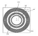
図示のように、例示的なラミネートパネル400は、複数のB0層(410a,410b)を含み、複数のB0層は、それらの上に形成される1以上のB0コイルを有する。B0コイルは、適切な電流が(複数の)コイルに提供されるときに、低磁場MRIシステムのためのB0磁場の少なくとも部分を生成するように構成される。幾つかの実施態様において、各B0層は、導電層の上にパターン化された導電性トレースの1以上の巻きを含んで、所望のB0磁場の部分を生成する。図示のように、層410aは、その上にコイル411aをパターン化させ、コイル411aは、任意の所望の幾何学的構成に従ってパターン化させられてよい。例えば、コイル411aは、概ね円形の幾何学的構成に従ってパターン化された、導電性トレースの1以上の巻きを有してよい。コイル411aは、(例えば、層の間を介して)層410bの上にパターン化されたコイル411bに電気的に接続されてよく、コイル411bも、任意の所望の幾何学的構成(例えば、導体の1以上の巻きを有する概ね円形のコイル)であってよい。As shown, the
その上に形成されるB0コイルを有する任意の適切な数の層が、層410a及び410b(例えば、1、10、20、50以上の層等)の間に介装され且つ電気的に接続されてよく、各層は、その上に形成される1以上のそれぞれのコイルを有し、それぞれのコイルは、適切な電流で通電させられるとき、低磁場MRIにおける使用のために構成されるB0磁場の少なくとも部分をもたらすことが理解されるべきである。各層は、単一のコイル又は多数のコイルを有してよく、各コイルは、所望のコイル設計の磁気特性及び/又は電気特性を達成するよう、その上に形成される任意の数の巻きを有するようにパターン化されてよいことが理解されるべきである。Any suitable number of layers having a B0 coil formed thereon is interposed and electrically connected between
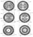
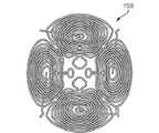
発明者は、MRIコンポーネントを設計し且つ製造するためにラミネート技法を用いることが、低磁場MRIシステムのためのB0コイルを製造する従来的な技法を用いては現実的でない或いは可能でない任意の幾何学的構成及び形態を有するB0コイルの加工を可能にし、実質的にあらゆる幾何学的構成、形態及び/又は配置のコイル設計を可能にすることを認識し且つ理解した。幾つかの実施態様によれば、その上に1以上のコイル又はその部分が形成される少なくとも幾つかのB0層を、他の層と異なる幾何学的構成を用いてパターン化して、所望のB0磁場を達成してよい。以下に更に詳細に議論するように、幾つかのB0層は、異なる用途及び環境のためにB0磁場を同調させるよう或いは所望の強度及び/又は同質性のB0磁場を較正し又はその他の方法で達成するためにB0磁場を調節するよう独立して制御され得る1以上のコイルをその上に形成してよい。The inventor has found that using laminating techniques to design and fabricate MRI components is not feasible or possible using conventional techniques to fabricate B0 coils for low field MRI systems. It has been recognized and understood that it allows for the fabrication of B0 coils having geometric configurations and configurations, and allows for coil designs of virtually any geometric configuration, configuration and/or arrangement. According to some embodiments, at least some of the B0 layers on which one or more coils or portions thereof are formed are patterned with a different geometric configuration than the other layers to achieve the desired A B0 magnetic field may be achieved. As discussed in more detail below, some B0 layers tune the B0 field for different applications and environments, or calibrate the B0 field of desired strength and/or homogeneity or otherwise. One or more coils may be formed on it that may be independently controlled to adjust the B0 field to achieve the above method.
具体的なコイル幾何学的構成又はコイル幾何学的構成の組み合わせ及びラミネートパネル内のコイルの配置及び分布の選択は、少なくとも部分的に、低磁場MRI用途との使用のために生成されるべき所望のB0磁場に依存することがある。加えて、同じ又は異なるB0コイル設計を有する1以上のラミネート層は、多数の層の上の導電性トレースを接続する1以上のビアによって接続されてよい。幾つかの実施態様において、ビアの場所は、結果として得られるB0磁場の同質性に対するそれらの影響を最小にするよう並びに/或いは通電されるコイルの1以上の電気特性を概ね最適化させるよう選択されてよい。低磁場MRIにおける使用のためのB0磁場を少なくとも部分的に毛伊勢得するために用いられてよいB0コイル設計の非限定的な実施例を以下に更に詳細に記載する。Selection of specific coil geometries or combinations of coil geometries and placement and distribution of coils within laminate panels should be created, at least in part, for use with low field MRI applications. May depend on the B0 magnetic field. Additionally, one or more laminate layers having the same or different B0 coil designs may be connected by one or more vias that connect the conductive traces on multiple layers. In some embodiments, the locations of the vias are to minimize their effect on the homogeneity of the resulting B0 field and/or to generally optimize one or more electrical properties of the energized coil. May be selected. Non-limiting examples of B0 coil designs that may be used to at least partially acquire B0 fields for use in low field MRI are described in further detail below.
ラミネート技法はそのような高い精度及び正確性で導電体をパターン化し得るので、B0磁石(又はその任意の部分)が、所望の強度及び同質性のB0磁場を達成する特定のB0磁石のための設計仕様に従って高い忠実度(fidelity)で確実にラミネートパネル形態内に加工されることがある。加えて、ラミネートパネルの多数の層の上にB0磁石(又はその部分)を形成する1以上のB0コイルを分配する能力は、B0磁石を生産する従来的な技法を用いては可能でない方法において所望のB0磁場を生成するよう、B0磁石のパラメータを最適化させることを可能にする。所望のB0磁場をもたらすために、数多くの幾何学的構成、形態及び/又は配置の中から選択するよう(例えば、B0磁場に寄与する各層の上の導電体の位置、幾何学的構成又は他の特性は、概ね最適化される)、シミュレーションが用いられてよい。次に、結果として得られる設計が、適切なラミネート技法を用いて精密に且つ正確に加工されてよい。Lamination techniques can pattern conductors with such high precision and accuracy so that a B0 magnet (or any portion thereof) can be a specific B0 magnet that achieves a desired strength and homogeneous B0 magnetic field. It may be processed in laminated panel form reliably with high fidelity according to design specifications for. In addition, the ability to distribute one or more B0 coils forming B0 magnets (or portions thereof) over multiple layers of a laminated panel is possible using conventional techniques for producing B0 magnets. Allows the parameters of the B0 magnet to be optimized to produce the desired B0 magnetic field in anon- native manner. To choose from a number of geometric configurations, morphologies and/or arrangements to provide the desired B0 magnetic field (eg, the location of the conductors on each layer that contributes to the B0 magnetic field, the geometric configuration). Or other properties are generally optimized), simulations may be used. The resulting design may then be precisely and accurately processed using suitable laminating techniques.
幾つかの実施態様によれば、減少された電力要求で所望のB0磁場の生成を促進するために或いは磁性材料を用いないで必要に応じて同じ電力要求を用いてより高いB0磁場を生成するために、1以上のラミネート層が磁性材料でパターン化された1以上の層のような(複数の)受動的な磁性コンポーネントを含んでよい。例えば、ラミネートパネル400は、所望のB0磁場を達成するために1以上B0コイルによって生成される磁場に寄与する磁性コンポーネント416を形成するよう配置された鉄材料又は他の磁性材料でパターン化された1以上のラミネート層415を含んでよい。そのような磁性材料は磁場を生成する電源を必要とせずに磁場を生成し或いは調整する(tailor)ので、所望のB0磁場が減少された電力要求でもたらされることがある。加えて、電力要求の対応する増大を伴わずにより高いB0磁場をもたらすために磁性材料を用い得るので、磁性材料は、潜在的には0.2Tを超える(例えば、0.2T〜0.5Tの間の)より高いB0磁場を有する低磁場MRIシステムの構築を促進することがある。According to some embodiments, a higher B0 magnetic field is used to facilitate the production of the desired B0 magnetic field with reduced power demand or with the same power demand as needed without the use of magnetic material. To produce, one or more laminated layers may include passive magnetic component(s), such as one or more layers patterned with magnetic material. For example, the
1以上の層415の上に形成される(複数の)磁性コンポーネント416は、所望の磁場強度及び/又は同質性のB0磁場を生成する或いは調整するのを助ける比較的高い透磁率(μ)を有する材料のいずれか1つ又は組み合わせを含んでよい。(複数の)磁性コンポーネント416は、所望の磁場をもたらすよう、シートとして提供された或いはその他の方法で製造され且つ1以上のラミネート層内に組み込まれた、1以上のパターン化された層によって形成されてよい。上で議論したように、受動的な磁性コンポーネントの使用は、所与のB0磁場をもたらすために必要とされる電力要求を減少させ得る。換言すると、所望のB0磁場の部分を受動的に(例えば、コンポーネントを作動させるのに電源を必要とせずに)生成し得るので、能動的な磁性コンポーネント(例えば、1以上の所望のB0コイル)に対する負担を軽減し得る。結果的に、減少させられた電流で1以上のB0コイルを作動させて、(複数の)磁性コンポーネント16との組み合わせにおいて、所望の磁場強度及び/又は同質性を有するB0磁場をもたらし得る。能動的な磁性コンポーネントの電力供給を減少させることは、磁性コンポーネントを駆動させるパワーエレクトロニクスの費用及び複雑性を単純化し、ラミネートパネルの熱出力の対応する削減をもたらし、そして、所望の強度及び/又は同質性のB0磁場を生成する際の能動的な磁性コンポーネントに対する制約をその他の方法で和らげることもある。The magnetic component(s) 416 formed over the one or
上で議論したように、ラミネートパネルは、低磁場MRIシステムにおいて作動させられるときに、検出されるMR信号の空間符号化を提供するのに適した磁場を生成し得る或いはそのような磁場に寄与し得る、1以上の勾配コイル又は1以上の勾配コイルの部分を形成するようにパターン化された、少なくとも1つの導電層を更に含んでよい。図4に例示する実施例において、ラミネートパネル400は、複数のラミネート層(420a,420b,420c)を含み、複数のラミネート層の上には、勾配コイル(421a,421b,421c)が形成されている。(複数の)層420aは、Z勾配コイル421aの全部又は部分を形成するようにパターン化された導電性トレースを含み、(複数の)層420bは、Y勾配コイル421bの全部又は部分を形成するようにパターン化された導電性トレースを含み、(複数の)層420cは、X勾配コイル421cの全部又は部分を形成するようにパターン化された導電性トレースを含む。上で議論したいように、図4中の勾配コイル421a,421b,421cの描写は、任意の数及び形態の層を用いて1以上の所望の勾配コイルを提供する任意の適切な幾何学的構成の勾配コイルを一般的に提示することが意図されている。 As discussed above, the laminate panel may generate or contribute to a magnetic field suitable to provide spatial coding of the detected MR signal when operated in a low field MRI system. It may further include at least one electrically conductive layer patterned to form one or more gradient coils or portions of one or more gradient coils. In the embodiment illustrated in FIG. 4, the
勾配コイルがラミネートパネル(例えば、ラミネートパネル400)内に少なくとも部分的に形成された1つの非限定的な実施例として、概ね円形の幾何学的構成を用いて、1以上の層内に少なくとも部分的に、Z勾配コイルが形成されてよく、(例えば、図1に概略的に例示する幾何学的構成に類似する)格子(グリッド)のようにパターン化された1以上の導電体を介してのように、概ね長方形の幾何学的構成を用いて、1以上の層内に少なくとも部分的に、X勾配コイル及びY勾配コイルが形成されてよい。勾配コイルのための導体は、低磁場MRIシステムの他の磁性コンポーネントを備える或いは備えない並びに他の磁性コンポーネントと層を共用する且つ/或いはラミネートパネルの別個の層の上にパターン化される統合された勾配コイルをもたらすために、所望に任意の組み合わせにおいて1つの又は多数の層に亘って分散させられてよい。 As one non-limiting example in which a gradient coil is at least partially formed within a laminate panel (eg, laminate panel 400), a generally circular geometry is used to at least partially within one or more layers. Optionally, a Z-gradient coil may be formed, via one or more conductors patterned like a grid (eg, similar to the geometrical configuration schematically illustrated in FIG. 1). As such, a generally rectangular geometry may be used to form the X and Y gradient coils at least partially within one or more layers. The conductors for the gradient coils are integrated with or without other magnetic components of the low field MRI system and sharing layers with other magnetic components and/or patterned on separate layers of the laminate panel. May be distributed over one or multiple layers in any combination as desired to provide a gradient coil.
その上にB0コイル及び勾配コイルの両方を備えるラミネートパネルの幾つかの実施態様において、ラミネートパネルの少なくとも1つの層は、低磁場撮像用途のための所望の磁場特性を提供するよう選択的に制御されてよい、B0コイル(又はその部分)及び勾配コイル(又はその部分)の両方を含んでよい。幾つかの実施態様では、ラミネートパネルの層の上の同じ導電性トレースの少なくとも部分が、コイルがどのように作動させられるかに依存して、B0コイルとして或いは勾配コイルとして機能してよい。幾つかの実施態様によれば、勾配コイルが多数の層に亘って分散させられてよく、幾つかの実施態様によれば、多数の勾配コイル(又はその部分)が単一の層内に形成されてよい(例えば、X、Y及び/又はZ勾配コイルのうちの1以上)。何故ならば、本明細書中に記載する技法は、ラミネートパネル又は多数のラミネートパネルの多数の層に亘って(複数の)磁性コンポーネントを分散させる如何なる特定の方法にも限定されないからである。ラミネート技法を用いて加工される1以上の勾配コイルが、(例えば、1以上の勾配コイルを共用される又は別個のラミネートパネル内に統合させることによって)ラミネート技法を用いて加工される1以上の他の磁性コンポーネントとの関係において利用されてよく、或いは低磁場MRIシステムの部分として従来的な技法を用いて加工される1以上の他の磁性コンポーネントとの関係において利用されてよいことが、理解されるべきである。In some embodiments of the laminate panel having both a B0 coil and a gradient coil thereon, at least one layer of the laminate panel is selectively selected to provide desired magnetic field properties for low field imaging applications. It may include both B0 coils (or parts thereof) and gradient coils (or parts thereof) that may be controlled. In some implementations, at least a portion of the same conductive traces on the layers of the laminated panel may function as a B0 coil or as a gradient coil, depending on how the coil is actuated. According to some embodiments, gradient coils may be distributed over multiple layers, and according to some embodiments multiple gradient coils (or portions thereof) are formed in a single layer. (Eg, one or more of X, Y and/or Z gradient coils). This is because the techniques described herein are not limited to any particular method of distributing magnetic component(s) over multiple layers of a laminated panel or multiple laminated panels. One or more gradient coils that are processed using a laminating technique are one or more gradient coils that are processed using a laminating technique (eg, by integrating one or more gradient coils in a shared or separate laminating panel). It is understood that it may be utilized in connection with other magnetic components, or in relation to one or more other magnetic components that are processed using conventional techniques as part of a low field MRI system. It should be.
同様に上で議論したように、ラミネートパネルは、B1励起場を生成することによってMR応答を刺激するように構成される(送信)並びに/或いはB0磁場及び対応する勾配場を生成するように構成されるコイルと共に作動させられるときに発せられるMR信号を受信するように構成される(受信)、1以上の送信/受信コイル又は1以上の送信/受信コイルの部分を形成するようにパターン化された少なくとも1つの導電層を更に含んでよい。そのようなラミネートパネルは、単一チャネル又は平行MRIを遂行するために単一の送信コイル及び/又は受信コイル(若しくはそれらの部分)或いは多数の送信コイル及び/又は受信コイル(若しくはそれらの部分)を含んでよい。図4に例示する実施例において、ラミネートパネル400は、(複数の)層430を含み、複数の層の上には、送信/受信コイル431の全部又は部分が形成される。Also, as discussed above, the laminated panel is configured to stimulate the MR response by generating a B1 excitation field (transmission) and/or a B0 magnetic field and a corresponding gradient field. Configured to receive an MR signal emitted when actuated with a coil configured to (receive), one or more transmit/receive coils, or a pattern to form part of one or more transmit/receive coils It may further include at least one electrically conductive layer. Such laminated panels may include a single transmitter coil and/or receiver coil (or parts thereof) or multiple transmitter coils and/or receiver coils (or parts thereof) to perform single channel or parallel MRI. May be included. In the embodiment illustrated in FIG. 4,
任意の適切な幾何学的構成を用いて、送信/受信コイル又は送信/受信コイルのセットをパターン化させてよい。例えば、幾つかの実施態様では、螺旋形状の導体を1以上の層内にパターンさせて、1以上の送信/受信コイル(又はその部分)を形成してよい。幾つかの実施態様によれば、実質的に長方形の幾何学的構成を利用して、ラミネート技法を用いて1以上の送信コイル及び/又は受信コイルを加工してよい。送信及び受信のために異なるコイルを用いる幾つかの実施態様によれば、送信及び受信コイルは、異なるそれぞれの幾何学的構成を用いて1以上の層内に形成されてよい。幾つかの実施態様では、多数の層及び/又は多数のラミネートパネルを用いて、低磁場MRIシステムのための送信/受信コイル及び/又は送信/受信コイルのセットを集合的に形成してよい。ラミネート技法を用いて加工される1以上の送信/受信コイルは、(例えば、1以上の他の磁性コンポーネントを共用される又は別個のラミネートパネル内に統合することによって)ラミネート技法を用いて加工される1以上の他の磁性コンポーネントとの関係において利用されてよく、或いは低磁場MRIシステムの部分として従来的な技法を用いて加工される1以上の他の磁性コンポーネントとの関係において利用されてよいことが、理解されるべきである。 Any suitable geometry may be used to pattern the transmit/receive coil or set of transmit/receive coils. For example, in some implementations, spiral-shaped conductors may be patterned in one or more layers to form one or more transmit/receive coils (or portions thereof). According to some embodiments, a substantially rectangular geometry may be utilized to fabricate one or more transmitter coils and/or receiver coils using a laminating technique. According to some implementations that use different coils for transmit and receive, the transmit and receive coils may be formed in one or more layers using different respective geometries. In some embodiments, multiple layers and/or multiple laminated panels may be used to collectively form a transmit/receive coil and/or set of transmit/receive coils for a low field MRI system. One or more transmitter/receiver coils processed using a laminating technique are processed using a laminating technique (eg, by integrating one or more other magnetic components in a shared or separate laminating panel). May be utilized in connection with one or more other magnetic components, or may be utilized in connection with one or more other magnetic components processed using conventional techniques as part of a low field MRI system. It should be understood.
ラミネートパネルは、環境からの及び/又はMRIシステムのコンポーネントから生成される電磁エネルギがMRI磁気学によって生成される磁場を乱すのを防止するために且つ/或いは装置を電磁干渉からその他の方法で遮蔽するために配置される1以上の電磁遮蔽を形成するようにパターン化される、1以上の導電層を更に含んでよい。図4に例示する実施例において、ラミネートパネル400は、電磁遮蔽をもたらすために用いられる(複数の)層440を含む。単一の遮蔽層のみが示されているが、任意の適切な数の遮蔽層が任意の異なる数の場所で用いられてよく、1以上の遮蔽を形成するパターン化された(複数の)導電層が別個の層内に形成されてよく或いは他のコンポーネントがその上に形成される層の上に形成されてよい(例えば、他の磁性コンポーネント又は他の磁性コンポーネントの部分がその上に形成される1以上のラミネート層の未使用部分の上に電気的に隔離されてパターン化されてよい)ことが理解されるべきである。(複数の)遮蔽層440は、ラミネートパネル400の1以上の層内に導体メッシュをパターン化することによって形成されてよいが、遮蔽は、任意の所望の幾何学的構成を形成する任意の適切な導体パターンを用いて提供されてよく、その幾何学的構成は、それぞれの遮蔽がどこに提供されるか及び/又は特定の遮蔽を利用して抑制し或いは排除する電磁干渉の特性に基づき選択されてよいことが、理解されるべきである。 Laminated panels prevent electromagnetic energy generated from the environment and/or from components of the MRI system from disturbing the magnetic field generated by MRI magnetism and/or otherwise shield the device from electromagnetic interference. It may further include one or more conductive layers that are patterned to form one or more electromagnetic shields that are arranged to do so. In the example illustrated in FIG. 4,
電磁遮蔽は、能動的な遮蔽又は受動的な遮蔽をもたらすように構成されてよく、実施態様は、この点において限定されない。幾つかの実施態様において、ラミネートパネルの多数の層の上に形成される遮蔽は、1以上のビアを用いて接続される。従って、低磁場MRIのための少なくとも幾つかの遮蔽は、1以上の磁性コンポーネントが、1以上の別個の層の上で加工される或いは他の磁性コンポーネント(又はその部分が)が形成される1以上の層で加工される、1以上のラミネートパネル内に統合させられてよい。電磁遮蔽は、磁場、電場、又は両方の、静的な又は動的な遮蔽を含んでよい。 The electromagnetic shield may be configured to provide active or passive shielding, and implementations are not limited in this respect. In some embodiments, the shields formed on multiple layers of the laminated panel are connected using one or more vias. Thus, at least some shields for low field MRI include one or more magnetic components machined on one or more separate layers or other magnetic components (or portions thereof) formed. It may be integrated into one or more laminated panels processed with the above layers. Electromagnetic shielding may include static or dynamic shielding of magnetic fields, electric fields, or both.
所望の磁場の生成を促進するよう配置されるシムコイル(shim coils)が、ラミネートパネルの1以上の層の上にパターン化されてもよい。幾つかの実施態様によれば、ラミネートパネルは、(複数の)磁場を生成し或いは(複数の)磁場に寄与するように配置され且つ1以上のB0コイルによって生成されるB0磁場の同質性を改良するよう構成されて、所与の視野内のB0磁場をその他の方法で改良し且つ/或いはB0磁場に否定的な影響を与える他の磁場を相殺するよう、1以上のシムコイル又は1以上のシムコイルの部分を形成するようにパターン化された、少なくとも1つの導電層を含んでよい。図4に例示する実施例において、ラミネートパネル400は、(複数の)層450を含み、(複数の)層450の上には、1以上のシムコイル452(又はその部分)が形成される。少なくとも1つのB0コイルと少なくとも1つのシムコイルとを備えるラミネートパネルを含む実施態様について、少なくとも1つのシムコイルは、少なくとも1つのB0コイル(又はその部分)と共用される(しかしながら、少なくとも1つのB0コイル(又はその部分)から電気的に隔離される)導電層によって形成されてよく、或いは少なくとも1つのB0コイル(又はその部分)と別個の1以上の導電層内に形成されてよい。議論した他の磁性コンポーネントと同様に、ラミネート技法を用いて加工されるシムコイルは、ラミネート技法を用いて(例えば、共用される又は別個のラミネートパネル内にシムコイルを統合することによって)加工される他のコンポーネントと共に利用されてよく、或いは、低磁場MRIシステムの部分として従来的な技法を用いて製造される他のコンポーネントと共に利用されてよい。Shim coils arranged to facilitate the generation of the desired magnetic field may be patterned on one or more layers of the laminate panel. According to some embodiments, the laminate panel (s) to generate a magnetic field, or (s) B0 field homogeneity of generated by the disposed and one or more B0 coil to contribute to the magnetic field One or more shim coils configured to improve performance and otherwise improve the B0 field in a given field of view and/or cancel other fields that negatively affect the B0 field. Alternatively, it may include at least one conductive layer patterned to form a portion of one or more shim coils. In the example illustrated in FIG. 4,
上で議論したように、多数の低磁場MRIコンポーネント(又はそれらの部分)が、ラミネートパネルの単一の層(即ち、単一のラミネート層)の上に形成されてよい。即ち、多数の磁性コンポーネント又は多数の磁性コンポーネントの部分が、単一のラミネート層の同じ導電層の上にパターン化されてよい。例えば、単一のラミネート層の導電層は、(完全なB0磁石を形成する或いは完全なB0磁石に寄与する)1以上のB0コイル及び1以上の勾配コイル又は1以上の勾配コイルの部分を形成するようにパターン化されてよい。As discussed above, multiple low field MRI components (or portions thereof) may be formed on a single layer of a laminate panel (ie, a single laminate layer). That is, multiple magnetic components or portions of multiple magnetic components may be patterned on the same conductive layer of a single laminate layer. For example, the conductive layer of a single laminate layer, the (complete B0 to form a magnet or contribute to complete B0 magnet) one or more B0 coil and one or more gradient coil or one or more gradient coils It may be patterned to form portions.
更なる実施例として、ラミネートパネルの単一のラミネート層が、勾配コイルの全部又は部分及び送信/受信コイルの全部又は部分を形成するようにパターン化されてよい。勾配コイル及び送信/受信コイル(又はそれらの部分)は、ラミネート層の上に形成される少なくとも幾つかの導電要素を共用してよく、或いは、勾配コイル及び送信/受信コイル(又はそれらの部分)は、同じラミネート層の上に(例えば、互いに電気的に隔離されて)別個に形成されてよい。他の実施例として、ラミネートパネルの単一のラミネート層が、1以上のB0コイルの全部又は部分及び低磁場MRIシステムのためのB0磁場の同質性を同調するために用いられる1以上のシムコイルの全部又は部分を形成するようにパターン化されてよい。(複数の)シムコイル及び(複数の)B0コイル(又はそれらの部分)は、ラミネート層の上に形成される少なくとも幾つかの導電要素を共用してよく、或いは、(複数の)シムコイル及びB0コイル(又はそれらの部分)は、同じラミネート層の上に別個に(即ち、互いに電気的に隔離されて)形成されてよい。コンポーネント(又はそれらの部分の)あらゆる組み合わせは、特定の設計に従って所望に1以上の共用されるラミネート層内に同様に加工されてよいことが理解されるべきである。何故ならば、それらの特徴はこの点において限定されないからである。As a further example, a single laminate layer of a laminate panel may be patterned to form all or part of a gradient coil and all or part of a transmit/receive coil. The gradient coil and the transmit/receive coil (or portions thereof) may share at least some conductive elements formed on the laminate layer, or the gradient coil and the transmit/receive coil (or portions thereof). May be formed separately (eg, electrically isolated from each other) on the same laminate layer. As another example, a single laminate layer of a laminated panel may be used to tune all or part of one or more B0 coils and B0 magnetic field homogeneity for low field MRI systems. It may be patterned to form all or part of the shim coil. The shim coil(s) and B0 coil(s) (or portions thereof) may share at least some conductive elements formed on the laminate layer, or the shim coil(s) and B(s)The zero coils (or portions thereof) may be formed separately (ie, electrically isolated from each other) on the same laminate layer. It should be appreciated that any combination of components (or portions thereof) may be similarly processed within one or more shared laminate layers as desired according to a particular design. Because their features are not limited in this respect.
発明者は、幾つかの実施態様に従ってラミネートパネルの上に形成される幾つかの導体が、多数の機能、典型的には、別個のMRIコンポーネントによって遂行される機能の特性を遂行するように構成されてよい。異なる機能を遂行するよう同じ導体を目的変更すること(repurposing)によって及び/又は多数のコンポーネント又は多数のコンポーネントの部分の間でラミネートパネルのラミネート層を共用することによって、ラミネートパネルを製造することに関連する寸法及び費用は削減されることがある。 The inventor has constructed some conductors formed on a laminated panel according to some embodiments to perform a number of functions, typically those of a function performed by separate MRI components. May be done. Producing a laminated panel by repurposing the same conductor to perform different functions and/or by sharing a laminate layer of the laminated panel among multiple components or parts of multiple components. The associated size and cost may be reduced.
図4に示すラミネートパネル400のラミネート層の順序は例示の目的のために提供されているに過ぎず、層の任意の適切な順序付け(ordering)が用いられてよいことが理解されるべきである。即ち、多数の磁性コンポーネント(又はそれらの部分)がラミネートパネル内に統合されるとき、ラミネート層のいずれかの順序付けを用いて、統合される磁性コンポーネントの所望の順序を達成してよい。幾つかの実施態様において、層及び層の上に形成されるコンポーネントの形態は、少なくとも部分的に、非限定的に、電力消費、勾配線形性、B0磁場同質性、勾配強度、RF強度、熱的考察等を含む、1以上のシステム及び/又は撮像パラメータを最適化するための設計考察に基づき、選択されてよい。例えば、幾つかの実施態様において、1以上のB0コイルの全部又は部分を含む1以上の層は、低磁場MRIシステムの電力消費を減少させるよう、ラミネートパネルの(複数の)最内側層として配置されてよい。幾つかの実施態様では、ラミネートパネルの1以上の外側層が、電磁遮蔽をもたらすようにパターン化されてよい。従って、ラミネートパネルの層のあらゆる順序付けが用いられてよい。何故ならば、本明細書中に記載する技法は、この点において如何なる特定の形態との使用にも限定されないからである。It should be understood that the order of the laminate layers of the
上で議論したように、ラミネートパネル400は、ラミネート技法を用いて加工されてよい例示的なコンポーネントを例示するために、B0コイル、勾配コイル、送信/受信コイル、シムコイル、及び電磁遮蔽の全部又は部分を加工されて有するものとして示されているが、ラミネートパネルは、コンポーネントの任意の1つ又は組み合わせ或いはそれらの所望の部分を含んでよい。幾つかの実施例では、例示的なコンポーネントの少なくとも部分が、(例えば、それらのコンポーネントのために従来的な製造技法を用いることによって)(複数の)ラミネートパネルと別個に設けられる。例えば、幾つかの実施態様は、(複数の)ラミネートパネルを含み、ラミネートパネルは、その上に形成される1以上のB0コイルを有し、低磁場MRIシステムの他のコンポーネントは、(複数の)ラミネートパネルと別個に設けられる。他の実施態様は、ラミネートパネルを含み、ラミネートパネルは、その上に形成される1以上の勾配コイルを有し、低磁場MRIシステムの他のコンポーネントは、ラミネートパネルと別個に設けられる。例えば、そのような実施態様において、低磁場MRIシステムのための主磁場B0は、(図1における2平面B0コイルアーキテクチャとの関係において記載したような)従来的な技法を用いて製造されてよく、送信/受信コイルは、撮像されるべき物体の周りに又は付近に配置されるヘルメットに基づく(helmet-based)及び/又は表面に置かれる(surface-based)コイルによって提供されてよい。他の実施態様において、ラミネートパネルは1以上のB0コイル及び1以上の勾配コイル(又はそれらの部分)の両方をそれらの上に形成してよく、低磁場MRIシステムの他のコンポーネントは(複数の)ラミネートパネルと別個に生産される。As discussed above, the
従って、本明細書中に記載する技法に従って製造されるラミネートパネルは、任意の適切な数の層を含んでよく、層の上には、低磁場MRIコンポーネント(又はそれらの部分)のいずれか1つ又は組み合わせが形成され、そのような(複数の)ラミネートパネルは、任意の数の他の(複数の)ラミネートパネル或いは他の技法を用いて生産される他のコンポーネントのいずれか1つ又は組み合わせとの関係において利用されてよい。何故ならば、それらの特徴はこの点において限定されないからである。幾つかの実施態様によれば、1以上の磁性コンポーネントがラミネート技法を用いて加工される部分及び従来的な技法を用いて生産される部分で実施される、混成アプローチが用いられてよい。 Thus, a laminated panel made in accordance with the techniques described herein may include any suitable number of layers on which any one of the low field MRI components (or portions thereof). One or a combination of any one or a combination of any number of other laminated panel(s) or other components produced using other techniques. May be used in connection with. Because their features are not limited in this respect. According to some implementations, a hybrid approach may be used in which one or more magnetic components are implemented in a portion that is processed using laminating techniques and a portion that is produced using conventional techniques.
上で議論したように、磁性コンポーネントは、部分的に又は全体的に、任意の数の異なる形態においてラミネートパネルの複数の層の上に(複数の)磁性コンポーネントの部分を分配することによって加工されてよい。図5は、幾つかの実施態様に従った多層ラミネートパネル500を例示しており、多層ラミネートパネル500は、その中に加工されたB0コイルを有する。図5は、通電されるときに、低磁場MRIを遂行するのに適したB0磁場に寄与する磁場をもたらすよう、B0コイルの部分がラミネートパネルの多数の層に亘ってどのように分配されてよいかの幾つかの実施例を示している。例示的な層は、その中に加工されるB0コイルの部分を図式的に例示しているが、以下に更に詳細に議論するように、各層は、他の磁性コンポーネント(例えば、1以上の勾配コイル、送信/受信コイル、シムコイル等)を含む、他のコンポーネントを含んでよい(しかしながら、含まなくてもよい)。As discussed above, the magnetic component is fabricated, partially or wholly, by distributing portions of the magnetic component(s) over multiple layers of a laminate panel in any number of different configurations. You can FIG. 5 illustrates a multi-layer laminate panel 500 according to some embodiments, the multi-layer laminate panel 500 having a B0 coil machined therein. FIG. 5 shows how portions of the B0 coil are distributed over multiple layers of the laminate panel to provide a magnetic field that, when energized, contributes to a B0 magnetic field suitable for performing low field MRI. 7 illustrates some examples of what may be done. The exemplary layers schematically illustrate the portion of the B0 coil machined therein, but as will be discussed in more detail below, each layer is associated with another magnetic component (eg, one or more). Other components may (but need not) be included, including gradient coils, transmit/receive coils, shim coils, etc.).
例示的なラミネートパネル500は、14個のラミネート層を含み、それらの上には、B0磁石の部分が、それぞれの導電層を相応してパターン化することによって分配されている。図5において、例示的な層の上に提供される導電性パターンは、概ね円形のコイルによって例示されており、その幅は、それぞれのコイルを形成する巻きの数を代表的な方法において示している。コイルは、通電されるときに、実線で表されたコイルを通じる電流が破線で表されたコイルを通じる電流と反対方向に流れること(例えば、時計回り対反時計回り又はその逆)を示すよう、実線及び破線で表されている。例示的なラミネートパネル500は、その上に加工された並びにほんの一例として以下に記載する方法において分配された、コイル510A、510B、510C、510D、510E、510F、及び510Gを含む。The exemplary laminate panel 500 includes 14 laminate layers on which the portions of B0 magnets are distributed by correspondingly patterning the respective conductive layers. In Figure 5, the conductive pattern provided on the exemplary layers is illustrated by generally circular coils, the width of which, in a typical manner, indicates the number of turns forming each coil. There is. The coil, when energized, indicates that the current through the coil represented by the solid line flows in the opposite direction to the current through the coil represented by the dashed line (eg, clockwise versus counterclockwise or vice versa). , Solid line and dashed line. An exemplary laminate panel 500 includes coils 510A, 510B, 510C, 510D, 510E, 510F, and 510G processed thereon and distributed in the manner described below by way of example only.
図5中の例示的な層1−14の各々は、複数の巻き、例えば、20巻きの導電性トレースをそれぞれ含むコイル510Aをそれらの上に加工している。即ち、描写する層内に示すように、24個の層の各々は、20巻きの導電性トレースを有するそれぞれの外側コイルを形成するようにパターン化されてよい。各コイル510Aは、層間の1以上のビア(例えば、めっきされた貫通穴、ピン、又は他の適切な導電性ビア)を用いて後続の層内のコイル510Aに接続されてよい。代替的に、外側コイル510Aの1以上は、他のコイル510Aから電気的に隔離されてよく、例えば、独立して通電されるように構成されてよい(例えば、コイル510Aの1以上は、シムコイルとして利用されてよい)。最初の6個の層(例えば、図5に例示する層1乃至6)の各々は、B0コイルに対する外側コイル510Aで構成されるが、(他の磁性コンポーネントを含む)他のコンポーネントが追加的にその上に加工されてよい。Each of the exemplary layers 1-14 in FIG. 5 has a coil 510A formed thereon that includes a plurality of turns, eg, 20 turns of conductive traces, respectively. That is, as shown in the depicted layers, each of the 24 layers may be patterned to form a respective outer coil having 20 turns of conductive traces. Each coil 510A may be connected to the coil 510A in a subsequent layer using one or more vias between layers (eg, plated through holes, pins, or other suitable conductive vias). Alternatively, one or more of the outer coils 510A may be electrically isolated from the other coils 510A, eg, configured to be independently energized (eg, one or more of the coils 510A may be shim coils). May be used as). Each of the first six layers (eg, layers 1-6 illustrated in FIG. 5) consists of an outer coil 510A for the B0 coil, but with other components (including other magnetic components) added. It may be processed on it.
層7乃至14の各々は、それぞれのコイル510Bをその上に加工してもよく、コイル510Bは、破線によって示すように、作動させられるときに、コイル510Aと反対方向に電流を伝えてよい。例示的なラミネートパネル500において、各コイル510Bは、それぞれの層の上に形成されるコイル510Aにおける巻きの数よりも少ない数の巻きを含む。コイル510Bを表すために用いられる減少する線幅によって示されるように、それぞれのコイルを形成する導電性トレースの巻きの数も、コイルがその上に分配される層に亘って減少してよい(或いはその他の方法で変化してよい)。例えば、層7及び8内のコイル510Bは、11個の巻きの導電性トレースをそれぞれ含んでよく、それぞれの層9乃至11内に加工されるコイル510Bは、10個の巻きで形成されてよく、層12内に加工されるコイル510Bは、9個の巻きで形成されてよく、そして、それぞれの層13及び14内に加工されるコイル510Bは、8個の巻きで形成されてよい。巻き形態は例示的であること並びに巻きの数及び巻きの数がどのように異なるか(或いは一定のままであるか)は如何なる点においても限定されないことが理解されるべきである。 Each of layers 7-14 may have a respective coil 510B fabricated thereon, which may conduct current in the opposite direction of coil 510A when actuated, as indicated by the dashed line. In the exemplary laminated panel 500, each coil 510B includes a smaller number of turns than the number of turns in coil 510A formed on the respective layers. The number of turns of conductive traces forming each coil may also be reduced over the layer over which the coil is distributed, as indicated by the decreasing linewidth used to represent coil 510B. Or it may change in other ways). For example, the coil 510B in layers 7 and 8 may each include eleven turns of conductive trace, and the coil 510B processed in each layer 9-11 may be formed of ten turns. , The coil 510B machined in layer 12 may be formed with 9 turns, and the coil 510B machined in each layer 13 and 14 may be formed with 8 turns. It should be understood that the winding configurations are exemplary and the number of windings and how the number of windings differ (or remain constant) are not limited in any way.
層7乃至14の各々は、それぞれのコイル510Cをその上に加工してもよく、それぞれのコイル510Cを加工は、コイルを表す実線によって示されるように、作動させられるときに、コイル510Aと同じ方向に電流を伝えてよい。例示的なラミネートパネル500において、各コイル510Cは、それぞれの層内でコイル510Bを形成する巻きの数よりも少ない巻きの数を含み、その数はコイル510Cをその上にパターン化するラミネート層に亘って変化してよく或いは同じままでよい。例えば、それぞれの層7乃至10内に加工されるコイル510Cは、6個の巻きで形成されてよく、層11内に加工されるコイル510Cは、5個の巻きで形成されてよく、それぞれの層12乃至14内に加工されるコイル510Cは、4個の巻きで形成されてよい。しかしながら、この配置(構成)は例示的であるに過ぎず、巻きの数及び巻きがどのように変化するか(或いは一定のままか)は、この例示的な配置(構成)において限定されない。 Each of the layers 7-14 may have a respective coil 510C processed thereon, the processing of each coil 510C being the same as the coil 510A when actuated, as indicated by the solid line representing the coil. Current may be transmitted in any direction. In the exemplary laminate panel 500, each coil 510C includes a number of turns less than the number of turns forming coil 510B in the respective layers, the number being in the laminate layer on which coil 510C is patterned. It may change over time or remain the same. For example, coil 510C machined in each layer 7-10 may be formed with 6 turns, and coil 510C machined in layer 11 may be formed with 5 turns, each The coil 510C processed in layers 12-14 may be formed of four turns. However, this arrangement (configuration) is merely exemplary, and the number of turns and how the windings change (or remain constant) are not limited in this example arrangement (configuration).
層7乃至11の各々も、それぞれのコイル510D及びそれぞれのコイル510Eをその上に加工しており、層7乃至9の各々は、それぞれのコイル510Fをその上に加工しており、層7及び9の各々は、それぞれのコイル510G及びそれぞれのコイル510Hをその上に加工している。図5に例示する実施例において、連続的なコイルは、作動させられるときに、それらが電流を伝える方向を交番し(alternate)、各連続的なコイルは、先行するコイルよりも少ない導体の巻きの数を含む。しかしながら、この形態は例示的であるに過ぎず、電流が伝えられる方向、各コイルにおける巻きの数、及びラミネートパネルの各層の上のコイルの数は、低磁場MRIのためのB0磁場を生成する或いは低磁場MRIのためのB0磁場に寄与するよう所望に選択されてよい。Each of layers 7-11 also has a respective coil 510D and a respective coil 510E processed thereon, and each of layers 7-9 has a respective coil 510F processed thereon. Each of the 9 has a respective coil 510G and a respective coil 510H machined thereon. In the embodiment illustrated in FIG. 5, the continuous coils alternate when they are energized in the direction they carry current, with each successive coil winding less conductors than the preceding coil. Including the number of. However, this configuration is merely exemplary, and the direction in which the current is conducted, the number of turns in each coil, and the number of coils on each layer of the laminate panel produce a B0 field for low field MRI. Or may be selected as desired to contribute to the B0 field for low field MRI.
コイル510Aとの関係において議論したように、図5に例示する例示的なコイルを形成する導体は、(以下に更に詳細に議論するような)互いに接続される内層(intra-layer)及び/又は層間の導電性ビアを用いて接続される中簡層(inter-layer)であってよい。更に、図5に例示するコイルの1以上は、隔離してパターン化されてよく、独立して通電させられることができてよい。このようにして、そのようなコイルは、(例えば、低磁場MRIシステムの較正中に)所与の環境において又は所与の荷重条件の下で結果として得られるB0磁場の同質性を改良するために必要に応じて作動させられ得るシムコイルとして用いられてよい。As discussed in connection with coil 510A, the conductors forming the exemplary coil illustrated in FIG. 5 may be intra-layer and/or interconnected (as discussed in more detail below). It may be an inter-layer connected using conductive vias between layers. Further, one or more of the coils illustrated in FIG. 5 may be separately patterned and may be independently energized. In this way, such a coil improves the homogeneity of the resulting B0 field in a given environment (eg during calibration of a low field MRI system) or under given loading conditions. May be used as a shim coil that can be activated as needed.
上で議論したように、同じラミネート層内に設けられるコイルは、作動させられるときに、電流が異なるそれぞれのコイル内で異なる方向に流れるように構成されてよい。例えば、所与のラミネート層の上にパターン化される1以上のコイルは、同じラミネート層内にパターン化される1以上の他のコイルの反対方向に電流を伝えてよい。図6Aは、B0コイルをその上にパターン化するラミネートパネルの例示的な層605を例示している(例えば、層605は、図5に例示する層12と類似であってよい)。層605は、コイル610A,610B、及び610Cを含み、各コイルは、複数の巻き(例えば、それぞれ20個の巻き、10個の巻き、及び5個の巻き)の導電性トレースを有する。図6Bは、図6Aに示す領域645を拡大して例示して、層605の上にパターン化された導電性トレース又はトラックに関する更なる詳細を示している。As discussed above, coils provided in the same laminate layer may be configured so that when actuated, current flows in different directions in each different coil. For example, one or more coils patterned on a given laminate layer may carry current in the opposite direction of one or more other coils patterned in the same laminate layer. FIG. 6A illustrates an
図6Bに例示するように、コイル610A,610B,610Cは、単一の導電性トレース615によって形成されており、導電性トレース615は、電流が導電性トレース615に提供されるときに、電流がコイル610A,610B,610Cに対して交番する反時計回り及び時計回り方向において伝えられるようにパターン化されている。具体的には、コイル610Aは、反時計回り方向に電流を伝え、コイル610Bは、時計回り方向に電流を伝え、コイル610Cは、反時計回り方向に電流を伝える。導電性トレース615は、電流が伝えられる方向に関して任意の所望の形態を実施するようにパターン化されてよいことが、理解されるべきである。例えば、多数のコイルがその上に加工される層は、電流が各コイルを通じて同じ方向に伝えられるようにパターン化されてよいが、各コイル又は電流伝導の方向は1以上の所望のコイルを通じて変更させられてよい。何故ならば、本明細書中に記載する技法は、如何なる特定の導体の形態又は電流の流れの方向との使用について限定されないからである。 As illustrated in FIG. 6B, the
図6A及び6Bは、例示的なビアも例示しており、それらのうちのビア675が図6Bに印されている。これらのビアは、(例えば、上述の図3A及び3Bに示す例示的なビアによって例示するように)1つのラミネート層の上にパターン化される導電性トレースを1以上の他のラミネート層の上にパターン化される導電性トレースと接続する。ビアは、隣接するラミネート層内の導電性トレースを接続するよう設けられてよく、且つ/或いは、任意の数の所望のラミネート層の上にパターン化される導電性トレースを接続するよう、多数の層を通じて設けられてよい。従って、ラミネートパネルの異なる層の上にパターン化される導電性トレースは、ラミネートパネル内に加工される磁性コンポーネント(又は他の電子コンポーネント)のための所望の回路構成をもたらすよう、任意の方法において接続されてよい。 6A and 6B also illustrate exemplary vias, of which via 675 is marked in FIG. 6B. These vias have conductive traces patterned on one laminate layer (eg, as illustrated by the exemplary vias shown in FIGS. 3A and 3B above) on one or more other laminate layers. Connect to the conductive traces that are patterned in. Vias may be provided to connect conductive traces in adjacent laminate layers, and/or multiple vias to connect conductive traces patterned on any number of desired laminate layers. It may be provided through layers. Thus, the conductive traces patterned on the different layers of the laminate panel are in any way desired to provide the desired circuitry for the magnetic components (or other electronic components) to be processed in the laminate panel. May be connected.
図5及び図6に関連して上で例示した例示的なコイルは、実質的に円形であり、実質的に均一な同心状の巻きを有するが、他の幾何学的構成及び形態を利用し得る。何故ならば、本明細書中に記載する技法は、如何なる特定の幾何学的構成又は形態との使用に限定されないからである。例えば、図7及び図8は、本明細書中に記載するラミネート技法を用いて実現してよいB0コイル設計の非限定的な実施例を図式的に例示している。剛性の支持構造の周りに正方形又は円形の導体を巻回することを典型的に含む従来的な生産技術を用いて低磁場MRIシステムのために実際的に実現され得るB0コイルと異なり、ラミネートプロセスの柔軟性及び精度の故に他の設計が実現されることがある。例えば、ラミネート技法を用いて形成されるB0コイルのための導電性トレースは、一般的に言えば、任意の所望の寸法に従って並びに任意の所望の幾何学的構成に従って、加工され且つパターン化されてよい。よって、従来的なワイヤ導体を用いては一般的に実現可能でない相対的な寸法を有する導電性経路が加工され得るし、従来的な製造技術を用いては可能であるとしても実際的でない幾何学的構成に従ってパターン化され得る。よって、ラミネート技法は、B0磁石のためのみならず、他の磁性コンポーネント(例えば、勾配コイル、送信/受信コイル、シムコイル等)のためにも、より最適なコイル設計の製造を促進することがある。The exemplary coils illustrated above in connection with FIGS. 5 and 6 are substantially circular and have substantially uniform concentric turns, but utilize other geometric configurations and configurations. obtain. This is because the techniques described herein are not limited to use with any particular geometry or form. For example, FIGS. 7 and 8 diagrammatically illustrate non-limiting examples of B0 coil designs that may be implemented using the laminating techniques described herein. Unlike B0 coils, which can be practically realized for low field MRI systems using conventional production techniques, which typically involve winding a square or circular conductor around a rigid support structure, a laminate Other designs may be realized due to the flexibility and accuracy of the process. For example, conductive traces for B0 coils formed using laminating techniques are generally processed and patterned according to any desired dimensions and according to any desired geometric configuration. You can Thus, conductive paths can be fabricated with relative dimensions that are not generally feasible using conventional wire conductors, and geometry that is impractical, if possible, using conventional manufacturing techniques. It can be patterned according to the biological composition. Thus, the laminating technique can facilitate the manufacture of more optimal coil designs not only for B0 magnets but also for other magnetic components (eg gradient coils, transmit/receive coils, shim coils, etc.). is there.
その上、ラミネート技法は、コイルが多数の(そして、幾つかの設計においては、比較的数多くの)層の上に分配されるのを可能にするので、各々の所与の層内のコイルの部分の寸法、位置、幾何学的構成等は、結果として得られる磁場を概ね最適化するよう選択されることがある。例えば、発明者は、各層の上の導電性パターンの1以上のパラメータを変えて、導体寸法、位置、幾何学的構成、巻きの数、及び/又は結果として得られる磁場に影響を与える各層の上の導電性パターンの任意の他の(複数の)パラメータのうちのいずれか1つ又は組み合わせに関する概ね最適な解決策を決定する、シミュレーションを開発した。異なるMRI用途は、異なる最適な解決策を有することがあるので、ラミネート技法は、特定のMRI用途のために調整される低磁場MRIシステムを設計し且つ実施するために利用されてよい。 Moreover, the laminating technique allows the coils to be distributed over a large number (and in some designs, a relatively large number) of layers, so that the coils within each given layer are The dimensions, positions, geometries, etc. of the parts may be selected to generally optimize the resulting magnetic field. For example, the inventor may change one or more parameters of the conductive pattern on each layer to affect the conductor size, position, geometry, number of turns, and/or the resulting magnetic field of each layer. Simulations have been developed that determine a generally optimal solution for any one or combination of any other parameter(s) of the conductive pattern above. Since different MRI applications may have different optimal solutions, laminating techniques may be utilized to design and implement low field MRI systems tailored for a particular MRI application.
図7A乃至7Cは、例えば、ラミネートパネルの単一の層の上にパターン化されてよい或いは多数のラミネート層の上に分散させられ且つ適切に配置されるビアを用いて接続されてよい複数の巻きを含む螺旋形B0コイル設計を例示している。図7Aは、1以上のラミネート層の上にパターン化された導電性材料の比較的広い螺旋形トレースを例示している。図7Bは、導電性経路の幅が図7Bに例示する導電性経路よりも細いが、巻きの数はより大きい、螺旋形B0コイル設計を示している。図7Cは、非均一な密度の螺旋の巻きを有する(即ち、螺旋幾何学的構成が内向きに動くに従い螺旋幾何学的構成がより緊密になる)、螺旋形B0コイル設計を示している。1以上の可変の密度の螺旋形B0コイルを用いることは、所与の円形のコイル設計に比べて、所望の強度のB0磁場を生産するのに必要とされる電力量を減少させることがある。そのような可変の螺旋形密度のB0コイルの製造は、典型的には、従来的なワイヤ包装技術(wire-wrapping techniques)を用いては実用的でなく或いは実現可能でない。他の螺旋に基づくB0コイル設計も可能であり、本明細書中に例示する幾何学的構成及び形態は、考え得るコイル設計の例であるに過ぎないことが理解されるべきである。FIGS. 7A-7C show, for example, a plurality of layers that may be patterned on a single layer of a laminate panel or connected using vias distributed and appropriately placed on multiple laminate layers. 3 illustrates a spiral B0 coil design including turns. FIG. 7A illustrates a relatively wide spiral trace of conductive material patterned on one or more laminate layers. FIG. 7B shows a spiral B0 coil design where the width of the conductive paths is narrower than the conductive paths illustrated in FIG. 7B, but with a larger number of turns. FIG. 7C illustrates a spiral B0 coil design with non-uniform density spiral windings (ie, the spiral geometry becomes tighter as the spiral geometry moves inward). . Using one or more variable density spiral B0 coils reduces the amount of power required to produce a desired strength B0 magnetic field as compared to a given circular coil design. There is. The manufacture of such variable helical density B0 coils is typically not practical or feasible using conventional wire-wrapping techniques. It should be understood that other spiral-based B0 coil designs are possible and the geometries and configurations illustrated herein are only examples of possible coil designs.
図8A乃至8Cは、ラミネートパネルの単一のラミネート層の上にパターン化されてよい或いは適切に配置されるビアを用いて多数のラミネート層の上に分散させられてよい複数の巻きを含む同心状のリングB0コイル設計を例示している。図8Aは、1以上のラミネート層の上に形成され且つ導体の巻きに関して均一な密度を有する導体材料の複数の接続された円形のトレースを例示している。図8Bは、ラミネート層の上に形成されるB0コイルの巻きの数及び密度の両方が、図8Aの設計と比べて増大させられているが、巻きの均一な密度を維持している、B0コイル設計を示している。図8Cは、同心状のコイルの非均一な密度の巻きを有するB0コイル設計を示している。他の円形ベースのB0コイル設計、例えば、図5、6及び10に関連して上述した例示的なB0コイル形態も可能であり、実施態様はこの点において限定されないことが理解されるべきである。8A-8C are concentric with multiple turns that may be patterned on a single laminate layer of a laminate panel or distributed over multiple laminate layers with vias appropriately positioned. 7 illustrates a ring-shaped B0 coil design. FIG. 8A illustrates a plurality of connected circular traces of conductor material formed on one or more laminate layers and having a uniform density with respect to the turns of the conductor. FIG. 8B shows that both the number of turns and the density of the B0 coil formed on the laminate layer are increased compared to the design of FIG. 8A, while maintaining a uniform density of turns. 4 shows a B0 coil design. FIG. 8C shows a B0 coil design with non-uniform density turns of concentric coils. It should be understood that other circular-based B0 coil designs are also possible, for example the exemplary B0 coil configurations described above in connection with FIGS. 5, 6 and 10, and embodiments are not limited in this respect. Is.
図4に関連して議論したように、ラミネート技法を用いて、部分的に、全体的に、及び/又は単独で若しくは1以上の他の磁性コンポーネントとの組み合わせにおいて、ラミネートパネル内に統合される勾配コイルを生産してよい。勾配コイルは、特定の実施に適した任意の所望の幾何学的構成に従ってパターン化されてよい。図9A乃至9Cは、幾つかの実施態様に従った例示的なx勾配コイル、y勾配コイル、及びz勾配コイルを例示している。例えば、図9Aは、ラミネートパネルの単一のラミネート層の上にパターン化される或いは多数のラミネート層の上に分散させられるx勾配コイル920Aの実施例を例示している。x勾配コイル920Aは、例えば、周波数符号化を行うように構成されてよい。同様に、y勾配コイル920Bは、単一の又は多数のラミネート層の上にパターン化されてよく、例えば、位相符号化をもたらすように構成されてよく、z勾配コイル920Cは、単一の又は多数のラミネート層の上のパターン化されてよく、例えば、画像スライスの局所化(localization)をもたらすように構成されてよい。しかしながら、勾配コイルは、任意の適切な空間符号化を行うように構成されてよい。図9A乃至9Cに例示するパターンは例示的であるに過ぎず、あらゆる形態又は幾何学的構成を用いて低磁場MRIのための勾配コイルを実施してよいことが理解されるべきである。何故ならば、本明細書中に記載する技術は、勾配コイルを実施するための如何なる特定の設計又は形態にも限定されないからである。 As discussed in connection with FIG. 4, using laminating techniques, partially, wholly, and/or integrated alone or in combination with one or more other magnetic components into a laminated panel. Gradient coils may be produced. The gradient coil may be patterned according to any desired geometrical configuration suitable for a particular implementation. 9A-9C illustrate exemplary x-gradient coils, y-gradient coils, and z-gradient coils according to some embodiments. For example, FIG. 9A illustrates an example of an
図10は、勾配コイルが少なくとも部分的にB0コイルを形成するコイルと同じ層の少なくとも一部の上に形成される、実施例を例示している。具体的には、図10は、ラミネートパネルの6個のラミネート層を例示しており、x勾配コイル1020A、y勾配コイル1020B、及びz勾配コイル1020Cは、B0磁石の部分と同じ層(例えば、その上に1以上のB0コイル又はその部分をパターン化させた層)内にパターン化されている。B0磁石に関して、コイル1010Aは、図5に例示するコイル510Aと類似してよい。発明者は、そのようなB0コイルの中心におけるラミネート層の領域が1以上の勾配コイル又はその部分をパターン化するために用いられてよいことを理解した。例えば、ラミネートパネルのそれぞれの層の上にパターン化されるB0コイル1020Aと共に、x勾配コイル1020Aは、層1000A及び1000Bの上にパターン化されてよく、y勾配コイル1020Bは、層1000C及び1000Dの上にパターン化されてよく、z勾配コイル1020Cは、層1000E及び1000Fの上にパターン化されてよい。勾配コイルは、ラミネートパネルの少なくとも幾つかの別個のラミネート層の上に全体的に又は部分的に勾配コイルをパターン化することを含む他の方法において、低磁場MRIB0磁石のためのB0コイルと共に同じラミネートパネル内に統合されてよいことが、理解されるべきである。何故ならば、多数の磁性コンポーネントをラミネートパネル内に統合することは、そのようにすることの如何なる特定の方法にも限定されないからである。磁性コンポーネントの合いで層を共用することによって、層の数を削減することがあり、よって、ラミネートパネルを製造するコストを削減することがある。FIG. 10 illustrates an embodiment in which the gradient coil is at least partially formed on at least a portion of the same layer as the coil forming the B0 coil. Specifically, FIG. 10 illustrates six laminate layers of a laminated panel, where the
図4と関連して上でも議論したように、1以上のシムコイルが、低磁場MRIシステムの1以上の他の磁性コンポーネントと共にラミネートパネル内に加工されてよい。図11A及び11Bは、所望の強度及び同質性のB0磁場を提供することに寄与する或いはそのようなB0磁場を提供することを助ける磁場をもたらすために、ラミネートパネルの1以上の層の上にパターン化されてよい、例示的なシムコイルを例示している。1つの非限定的な実施例として、シムコイル1150Aは、通電されるときに、対応する磁場をもたらすよう、1以上のラミネート層内にパターン化されてよい。コイル1150Aは、例えば、コイル1150Aが別個に給電され得るよう、コイル1150Aを同じラミネートパネル又は同じラミネート層内に提供される他の能動的なコンポーネントから電気的に隔離することによって、独立して通電されるように構成されてよい。図11Bに例示するコイル1150Bは、ラミネートパネル内に統合されるシムコイルを提供するための異なる例示的な幾何学的構成を示している。シムコイル1150Aと類似して、シムコイル1150Bは、独立して作動させられるように構成されてよい。As discussed above in connection with FIG. 4, one or more shim coils may be fabricated in a laminate panel with one or more other magnetic components of a low field MRI system. 11A and 11B, in order to provide a magnetic field that helps to provide a contributing or such the B0 field to provide a B0 field of the desired strength and homogeneity, of one or more layers of the laminate panels 3 illustrates an exemplary shim coil that may be patterned above. As one non-limiting example,
シムコイルは、所望の強度及び同質性のB0磁場の生成を促進する磁場に寄与する、あらゆる方法及び形態によって提供されてよいことが理解されるべきである。例えば、コイル1150A及び/又は1150Bは、単一の層の上にパターン化され或いは多数の層に亘って分配されてよく、各コイルは、層のみの上にパターン化されてよく、或いは1以上の層を1以上の他のコンポーネント又はその部分と共用してよい。その上、任意の所望の幾何学的構成を有する任意の数のシムコイルがラミネートパネル内に加工されてよい。何故ならば、その特徴はこの点において限定されないからである。幾つかの実施態様によれば、1以上のシムコイルは、低磁場MRIシステムの他の磁性コンポーネントと別個にラミネートパネル内に加工される。幾つかの実施態様によれば、シムコイルは、異なる組み合わせのシムコイルがシステムを作動させる所与の環境に応答して選択的にアクティブ化されることがあるよう、異なる幾何学的構成及び/又は場所に設けられてよい。作動するシムコイルの組み合わせを動的に選択する能力は、輸送可能に又は運搬可能に配置され得る低磁場MRIシステムの生産を促進することがある。上で議論したように、(例えば、同質性を向上させるために)B0磁場に寄与するシムコイルは、作動させられるとき、B0コイルである。何故ならば、それらは実際にはMRIシステムのB0磁場に寄与するからである。It should be appreciated that the shim coil may be provided by any method and configuration that contributes to the magnetic field that facilitates the generation of a desired strength and homogeneous B0 magnetic field. For example, the
幾つかの実施態様によれば、所望の強度及び同質性のB0磁場に寄与する磁場をもたらすために、1以上の受動的なシムコイルが利用されてよい。図3に関連して上で議論したように、そうするために電源を必要とせずに磁場を生成するために、磁性材料が利用されてよい。従って、磁性材料でパターン化される1以上の層は、所望のB0磁場をもたらすのを助けるために受動的なシムとして提供されてよい。本明細書中に記載する他のコンポーネントと同様に、受動的なシムは、任意の数、配置及び幾何学的構成において提供されてよく、単独で又は1以上の他のコンポーネントと共用される層の上で、単一の又は多数の層の上にパターン化されてよい。何故ならば、受動的なシムを提供する特徴は、如何なる特定の形態、幾何学的構成又は配置にも限定されないからである。受動的なシムは、任意の所望の幾何学的構成の磁性材料で構成される別個のシム要素を用いて提供されてよい。そのようなシム要素は、所望の場所で(例えば、接着剤又は他の取付け手段によって)それらの要素をパネルに取り付けることによってラミネートパネル内に組み込まれてよく、且つ/或いはそのようなシム要素は、所望の場所でラミネートパネルと別個に配置されてよい。何故ならば、それらの特徴は、1以上の受動的なシムを低磁場MRIシステム内に組み込む如何なる特定の方法にも限定されないからである。According to some embodiments, one or more passive shim coils may be utilized to provide a magnetic field that contributes to the desired strength and homogeneity of the B0 field. As discussed above in connection with FIG. 3, magnetic materials may be utilized to generate the magnetic field without the need for a power source to do so. Thus, one or more layers patterned with magnetic material may be provided as passive shims to help provide the desired B0 field. As with the other components described herein, passive shims may be provided in any number, arrangement, and geometrical configuration, either alone or as a layer shared with one or more other components. May be patterned on a single or multiple layers. This is because the features that provide passive shims are not limited to any particular form, geometry or arrangement. Passive shims may be provided using separate shim elements composed of magnetic material of any desired geometrical configuration. Such shim elements may be incorporated into a laminate panel by attaching them to the panel at desired locations (eg, by adhesive or other attachment means), and/or such shim elements may be , May be placed separately from the laminate panel at any desired location. Because, those features are not limited to any particular way of incorporating one or more passive shims into a low field MRI system.
前述において議論したように、ラミネート技法を用いて、任意の数の異なる組み合わせ及び形態において(複数の)磁性コンポーネントを生産してよい。例えば、発明者は、ラミネートパネル技法を用いてソレノイドコイル設計に従った低磁場MRIシステムを実施してよく、生成されるB0磁場は、高磁場MRIシステムを実施するために頻繁に用いられる設計である、ソレノイドコイルの中心を通じる軸に沿って方向付けられてよいことを更に認識し且つ理解した。具体的には、幾つかの実施態様によれば、1以上のソレノイドコイルが、撮像されるべき物体を位置付けてよい1以上のソレノイドに基づくコイルの中心を通じる視野を創るように配置される複数の接続されたラミネートパネルの上に形成されてよい。As discussed above, laminating techniques may be used to produce magnetic component(s) in any number of different combinations and configurations. For example, the inventor may implement a low field MRI system according to a solenoid coil design using a laminated panel technique, and the generated B0 field is a design often used to implement a high field MRI system. It has been further recognized and understood that it may be oriented along an axis through the center of the solenoid coil. Specifically, according to some implementations, one or more solenoid coils are arranged to create a field of view through the center of the one or more solenoid-based coils that may position the object to be imaged. May be formed on top of the connected laminated panels.
図12は、幾つかの実施態様に従った、低磁場MRIにおける使用のためのソレノイドB0磁石を含む、その上に加工された磁性コンポーネントを有する複数のラミネートパネルを含む、磁性装置1200を例示している。図示のように、磁石装置1200は、撮像されるべき物体をその中に配置してよい八角形チューブを形成する、8個の接続されたラミネートパネルを含む。ソレノイド磁石は、各々のラミネートパネルの上でパターン化される複数の導電性セグメントを接続することによって形成されるB0コイル1210を含む。ラミネートパネルは、隣接するラミネートパネルの上に形成される導電性セグメントの間の安定的な接続を保証する任意の適切な方法(例えば、1以上の導電性接着剤、噛み合い得る或いはその他の方法で取り付けられ得る部分、又は隣接するラミネートパネルの間の適切な電気的又は機械的な接続を行うために用いられてよい任意の他の適切なコネクタ)において接続されてよい。接続されて適切な電流で通電されるとき、ラミネートパネルの上にパターン化される導電性セグメントは、磁性装置1200の長手(Z)方向においてB0磁場を生成するソレノイドB0コイル1210を形成する。B0コイル1210の巻線は、ソレノイドコイルが複数のラミネートパネルを介してどのように実施され得るかを例示するように図式的である。FIG. 12 illustrates a
図12における実施例において、磁性装置1200は、対向するラミネートパネルの上に形成される並びにx方向において勾配磁場を生成するように構成されるx勾配コイル1220a,1220b及び対向するラミネートパネルの上に形成される並びにy方向において勾配磁場を生成するように構成されるy勾配コイル1230a,1230bも含む。加えて、磁性装置1200は、B0コイル1210と類似するソレノイド幾何学的構成を有するが、磁性装置1200の両端に形成され且つ例えばz方向におけるスライス選択を可能にするように構成される、z勾配コイル1240a,1240bも含む。勾配コイルの幾何学的構成及び形態は例示的であり、勾配磁場は導体の他のパターンを用いて生成されてよい。何故ならば、それらの特徴は、この点において限定されないからである。In the embodiment in FIG. 12, a
図12に例示するラミネートパネルは、任意の所望の数の層を有するラミネートパネルを提示していることが理解されるべきである。即ち、各ラミネートパネルは単一の層を含んでよく、或いは、各ラミネートパネルは多数の層を含んでよく、多数の層の各々は、1以上の低磁場MRIコンポーネントの全部又は部分を形成させてよい。何故ならば、所望の磁性コンポーネントは、任意の所望の形態に従って加工されてよいからである。例えば、B0コイル1210は、図12に示すように多数のラミネートパネルの上に導電性セグメントを接続することによって形成されてよいのみならず、各ラミネートパネルの多数のラミネート層内に形成される導電性セグメントを接続することによって形成されてもよいからである。It should be understood that the laminate panel illustrated in FIG. 12 presents a laminate panel having any desired number of layers. That is, each laminate panel may include a single layer, or each laminate panel may include multiple layers, each of the multiple layers forming one or more low field MRI components in whole or in part. You can This is because the desired magnetic component may be processed according to any desired form. For example, the B0 coil 1210 may not only be formed by connecting conductive segments over multiple laminated panels as shown in FIG. 12, but is formed within multiple laminated layers of each laminated panel. This is because it may be formed by connecting the conductive segments.
低磁場RMIシステムのコンポーネントを製造するために本明細書中に記載するラミネート技法は極めて設定変更可能であり、任意の所望の幾何学的構成及び/又は大きさの導電性セグメントを用いて所望の設計に従った磁性装置を提供してよく、図12に例示する形態及び配置は幾つかの実施態様に従った実施例を例示するために提供されているに過ぎない。例えば、ラミネートパネルを任意の大きさ及び形状に形成し且つ互いに接続して所望の幾何学的構成を創り出してよい。よって、体の所望の部分に適合する並びにそれらの上に磁性コンポーネント及び/又は電子コンポーネントの任意の1つ若しくは組み合わせをパターン化させたラミネートパネルシステムが生産されてよい。幾つかの実施態様によれば、図12に関連して記載する技法は、所望の解剖学的構造を撮像するためのラミネートに基づくシステムを構築するために用いられてよく、磁性コンポーネントの任意の所望の組み合わせが、周りに形成された幾何学的構成を有する並びに所望の解剖学的構造に適合するように構成される一連の接続されたラミネートパネルの上に加工されてよい。例えば、一連の接続されたラミネートパネルは、以下に記載する図22A乃至22Cに関連して更に詳細に議論するように、頭を撮像するように構築されてよい。 The laminating techniques described herein for manufacturing components of low field RMI systems are highly configurable and can be used with conductive segments of any desired geometry and/or size to achieve the desired A magnetic device according to the design may be provided and the configurations and arrangements illustrated in Figure 12 are provided only to illustrate examples according to some embodiments. For example, laminate panels may be formed of any size and shape and connected together to create the desired geometrical configuration. Thus, a laminated panel system may be produced that fits the desired part of the body and is patterned with any one or combination of magnetic and/or electronic components thereon. According to some embodiments, the technique described in connection with FIG. 12 may be used to build a laminate-based system for imaging desired anatomy, and any of the magnetic components. The desired combination may be fabricated on a series of connected laminate panels that have a geometrical configuration formed around them and that are configured to fit the desired anatomy. For example, a series of connected laminate panels may be constructed to image the head, as discussed in more detail in connection with FIGS. 22A-22C described below.
前述において議論したように、ラミネート技法は、低磁場MRIシステムの1以上の磁性コンポーネントを生産する数多くの方法において利用されてよい。本明細書中に記載するラミネート技法を用いて生産されるラミネートパネルを利用する例示的な低磁場MRIシステムが図13に例示されている。具体的には、図13は、ラミネートパネル1310a,1310bが利用される、低磁場MRIシステム1300のコンポーネントを図式的に例示しており、ラミネートパネル1310a,1310bは、それらの上に加工された例磁場MRIシステムの1以上の磁性コンポーネントを有する。図13に例示する磁性コンポーネントの2平面配置は、図1に示すものと類似するが、従来的な技法を用いて生産される磁性コンポーネントよりもむしろ、ラミネート技法を用いてラミネートパネル1310a,1310bを介して提供される、1以上の磁性コンポーネントを備える。例えば、図1中のB0コイル110a,110b及び/又は勾配コイル120a,120bのような従来的な技法を用いて生産される1以上の磁性コンポーネントは、ラミネートパネル1310a,1310b内の統合された磁気学と置換されている。As discussed above, the laminating technique may be utilized in numerous ways to produce one or more magnetic components of a low field MRI system. An exemplary low field MRI system utilizing laminated panels produced using the laminating techniques described herein is illustrated in FIG. Specifically, FIG. 13 schematically illustrates components of a low
図13に例示する例示的なシステムにおいて、ラミネートパネル1310aは、1以上のB0コイル及び/又は1以上の勾配コイルを統合して、2平面コイル配置の1つの「側」を形成してよく、ラミネートパネル1310bは、同様に、1以上のB0コイル及び/又は1以上の勾配コイルを統合して、2平面配置の他の「側」を形成してよい。よって、2平面B0磁石は、作動させられるときに低磁場MRIを遂行するのに適したパネルの合いでB0磁場を生成するラミネート技法を用いて生産されてよい。発せられるMR信号を空間的に符号化する勾配コイルも、ラミネート技法を用いてラミネートパネル1310a,1310b内に統合されてよい。非限定的に、1以上の送信/受信コイル、1以上のシムコイル、遮蔽、パワーエレクトロニクス、熱消散コンポーネント等を含む、他の磁性コンポーネント及び/又は電子コンポーネントが、ラミネートパネル1310a,1310b内に加工されてよいことが、前述のことから理解されるべきである。In the exemplary system illustrated in FIG. 13, laminate panel 1310a may integrate one or more B0 coils and/or one or more gradient coils to form one “side” of a two-plane coil arrangement. ,
上で議論したように、ラミネートパネル形態において統合される磁気学を提供することは、非限定的に、比較的困難で繊細なコイル巻回及び整列、磁性コンポーネントの生産後整列、可搬性、生産後形態及び較正に対する制約等を含む、従来的な製造技法の1以上の欠点を回避することがある。更に、ラミネートパネル形態において統合される1以上の磁性コンポーネントを提供することは、低磁場RMIシステムの設計、製造及び据付けを単純化することがあるという、フレキシビリティ、確実性及び/又は測定可能性(scalability)ももたらすことがある。ラミネート技法を用いる統合される磁気学は、非限定的に、幾何学的構成及び形態に関する設計のフレキシビリティ、特定の用途のために磁気学を調整する能力、コストの削減、可搬性の増大、及び/又は低磁場MRIシステムのコンパクトさを含む、更なる利益をもたらすことがある。 As discussed above, providing integrated magnetics in a laminated panel form is, without limitation, relatively difficult and delicate coil winding and alignment, post-production alignment of magnetic components, portability, production. One or more shortcomings of conventional manufacturing techniques may be avoided, including posterior morphology and calibration constraints. Moreover, providing one or more magnetic components integrated in a laminated panel form may simplify the design, manufacturing and installation of low field RMI systems, which may be flexible, reliable and/or measurable. (scalability). Integrated magnetism using laminating techniques provides, without limitation, design flexibility with respect to geometric configurations and morphologies, the ability to tailor magnetism for specific applications, reduce costs, increase portability, And/or may provide additional benefits, including the compactness of the low field MRI system.
ラミネートパネル(例えば、ラミネートパネル1310a,1310b)は、B0コイル、勾配コイル、送信/受信コイル、シムコイル及び電磁遮蔽の任意の1つの又は組み合わせを統合してよく、磁性コンポーネント(又はそれらの部分)の如何なる特定の1つ又は組み合わせとの使用のためにも限定されないことが、前述のことから理解されるべきである。その中に統合されないあらゆる1以上の磁性コンポーネントは、任意の他の利用可能な技法を用いて提供されてよい(例えば、1以上の磁性コンポーネントは、それぞれの磁性コンポーネントを生産するための従来的な技法を用いて提供されてよい)。Laminate panels (eg,
幾つかの実施態様によれば、磁性コンポーネントは、混成技法を用いて生産されてよく、磁性コンポーネントの部分は、ラミネートパネル形態において生産されてよく、磁性コンポーネントの部分は、異なる技法を用いて製造される。例えば、図14aは、幾つかの実施態様に従った、B0コイルのための混成設計を例示している。混成設計は、コイル1405と、コイル1410A,1410B,1410Cをその中に有するラミネートパネル1410とを含む。コイル1405は、図1に関連して上で議論したような巻回コイルであってよく、或いは、通電されるときに低磁場MRIに適したB0磁場に寄与する磁場をもたらす1以上の積み重ねられた金属プレートであってよい。巻回導体によって形成されるコイルは、電磁石を形成するためにワイヤのような導体を巻回することによって生産されるコイルを指し、コイルを形成するために代わりに導体をパターン化するラミネート技法を用いて生産されるコイルと対照的である。同様に、ラミネートパネル1410の層の上にパターン化されるコイル1410A,1410B,1410Cは、通電させられるときに低磁場MRIに適したB0磁場に寄与する磁場を生成する。図14Aに例示する例示的な混成設計は、2平面設計の1つの側又は本明細書中に記載する幾何学的構成のいずれかにおける幾何学的構成若しくは切子面(facet)を表すことがある。よって、B0磁石は、低磁場RMIを遂行するのに適した所望のB0磁場をもたらすために、ラミネート技法及び非ラミネート技法を用いて構築されてよい。According to some implementations, the magnetic component may be produced using a hybrid technique, the portion of the magnetic component may be produced in a laminated panel form, and the portion of the magnetic component is produced using different techniques. To be done. For example, FIG. 14a illustrates a hybrid design for a B0 coil, according to some embodiments. The hybrid design includes a
ラミネートパネル1410は、任意の数のラミネート層の上に分配させられる任意の数のコイルを有する任意の所望のラミネートパネルの代表であるよう図式的に例示されていることが理解されるべきである。例えば、ラミネートパネル1410は、1以上のB0コイル(例えば、B0矯正又はシムコイル)、1以上の勾配コイル、及び/又は1以上のTx/Rxコイルを含んでよい。何故ならば、それらの特徴はこの点において限定されないからである。ラミネートパネル1410は、コイル1405に対して図14Aに示すような大きさとさせられる必要はなく、任意の大きさであってよく、コイル1405に対して任意の方法において位置付けられてよいことが更に理解されなければならない。何故ならば、図14Aに例示する混成設計は、所望のB0磁場、所望の勾配磁場、及び/又は所望のRF磁場を生成するために、ラミネートパネルが非ラミネート技法を用いて形成される1以上のコイルと共にどのように用いられてよいかの一例に過ぎないからである。It should be understood that the
図14Bは、幾つかの実施態様に従った混成磁石の部分を例示している。混成磁石1400’は、所望の磁場強度及び/又は同質性の磁場に寄与する磁場を生成するように構成されるコイル1405’を含む。コイル1405’は、特定の設計、及び/又は所望の磁場強度、インダクタンス、抵抗、電力要求等に適した回数の巻き(例えば、約10、50、100、150、200、250、500又はそれよりも多くの巻き)を用いて提供される導体(例えば、巻回銅導体、銅プレート等)によって形成される、コイルであってよい。コイル1405’は、任意の所望の大きさに構築されてよい。例えば、例示的なコイル1405’が、10〜50インチに及ぶ内径及び15〜80インチに及ぶ外径を有してよい。これらの範囲は例示のために過ぎず、コイル1405’は上で提供した例示的な範囲よりも大きく或いは小さく構築されてよいことが理解されるべきである。コイル1405’は、リボンワイヤ、円形ワイヤ、正方形ワイヤ、又は任意の他の適切な導体を用いて巻回されてよく、任意の適切なゲージ(gauge)を有してよい。導体は、銅、アルミニウム、又は任意の適切な材料であってよい。何故ならば、これらの特徴はこの点において限定されないからである。 FIG. 14B illustrates a portion of a hybrid magnet according to some embodiments. The hybrid magnet 1400' includes a coil 1405' that is configured to generate a magnetic field that contributes to a desired magnetic field strength and/or a homogeneous magnetic field. Coil 1405' may have a suitable number of turns (eg, about 10, 50, 100, 150, 200, 250, 500 or more) for a particular design and/or desired magnetic field strength, inductance, resistance, power requirements, etc. The coil may be formed by a conductor (eg, wound copper conductor, copper plate, etc.) provided with a large number of turns. Coil 1405' may be constructed to any desired size. For example, the exemplary coil 1405' may have an inner diameter ranging from 10 to 50 inches and an outer diameter ranging from 15 to 80 inches. It should be appreciated that these ranges are for illustration only, and that coil 1405' may be constructed larger or smaller than the example ranges provided above. The coil 1405' may be wound with ribbon wire, circular wire, square wire, or any other suitable conductor and may have any suitable gauge. The conductor may be copper, aluminum, or any suitable material. This is because these features are not limited in this respect.
混成磁石1400’は、1以上の磁性コンポーネントがその上にそれぞれパターン化された複数のラミネート層を有するラミネートパネル1410’も含む。例えば、幾つかの実施態様によれば、ラミネートパネル1410’は、各層が、所望の強度及び/又は同質性のB0磁場を達成するために、幾つかの場合には、選択的にそれぞれの磁場に寄与するよう作動させられ得る、その上にパターン化されたB0コイル(例えば、補完、矯正若しくはシムコイル)又はその部分を有する、複数の層を含む。追加的に又は代替的に、ラミネートパネル1410’は、各層が、x、y、及び/又はz方向において勾配磁場をもたらすよう、その上にパターン化された勾配コイル又はその部分を有する、複数の層を含んでよい。幾つかの実施態様によれば、ラミネートパネル1410’は、三次元において勾配磁場をもたらすよう、X勾配コイル、Y勾配コイル及びZ勾配コイルでそれぞれパターン化された、1以上の層を含む。ラミネートパネル1410’は、1以上の層の上にパターン化された他の磁性コンポーネント(例えば、1以上の無線周波数コイル)も含んでよい。何故ならば、これらの特徴はこの点において限定されないからである。The hybrid magnet 1400' also includes a laminate panel 1410' having a plurality of laminate layers each having one or more magnetic components patterned thereon. For example, according to some embodiments, the laminate panels 1410 ', to each layer, to achieve the B0 magnetic field of a desired intensity and / or homogeneity, in some cases selectively, respectively It comprises a plurality of layers having patterned B0 coils (eg complementary, corrective or shim coils) or parts thereof, which can be actuated to contribute to the magnetic field. Additionally or alternatively, the
ラミネートパネル1410’は、本明細書中に記載する技法のいずれかを用いて或いは任意の適切な技法を用いてその上に加工される磁性コンポーネント及び/又は電子コンポーネントのいずれか1つ又は組み合わせを含んでよいことが理解されるべきである。例えば、ラミネートパネル1410’は、図4、5、9A乃至C、10及び図11A乃至Bに例示し且つ付随する記述中に記載する磁性コンポーネントの種類及び組み合わせのうちのいずれかを含んでよい。ラミネートパネル1410’は、電子コンポーネント、遮蔽、受動的な素子等のような、他のコンポーネントも含んでよい。
ラミネートパネル1410’は、任意の適切な幾何学的構成及び寸法であってよい。具体的には、例示的な正方形のラミネートパネルは、8”×8”〜50”×50”に及ぶ寸法を有してよい。例えば、例示的なラミネートパネルは、約16”×16”、22”×22”、又は所与の設計のための任意の他の寸法を有してよい。例示的な非正方形のパネルは、同様に寸法取られてよい。ラミネートパネル1410’は、所望の磁性コンポーネントをその上に全体的に又は部分的にパターン化してよい任意の数の層(例えば、約10、20、30、50、又はそれよりも多くの層)で加工されてよい。パターン化される層は、所望の動作特性の観点からその上に加工される(複数の)磁性コンポーネントに適した厚さを有する、銅、アルミニウム、又はその他の材料で形成されてよい。例えば、ヘビー銅(例えば、5オンス、6オンス、7オンス、8オンス、10オンス等)を用いて1以上の磁性コンポーネントをパターン化してよく、且つ/或いはエキストリーム銅(例えば、20オンス、25オンス、30オンス、50オンス等)を用いて1以上の磁性コンポーネントをパターン化してよい。しかしながら、他の厚さの導体材料を用いてよい。何故ならば、これらの特徴はこの点において限定されないからである。ラミネートパネル1410’の全厚は、少なくとも部分的に、例示的な厚さが0.1インチ〜数インチに及ぶ、利用される層の数に依存する。 Laminate panel 1410' may be of any suitable geometry and size. Specifically, the exemplary square laminate panel may have dimensions ranging from 8"x8" to 50"x50". For example, an exemplary laminate panel may have about 16″×16″, 22″×22″, or any other dimension for a given design. Exemplary non-square panels may be similarly dimensioned. Laminated panel 1410' includes any number of layers (eg, about 10, 20, 30, 50, or more layers) on which desired magnetic components may be wholly or partially patterned. May be processed in. The patterned layer may be formed of copper, aluminum, or other material having a thickness suitable for the magnetic component(s) processed thereon in view of the desired operating characteristics. For example, heavy copper (eg, 5 ounces, 6 ounces, 7 ounces, 8 ounces, 10 ounces, etc.) may be used to pattern one or more magnetic components and/or extreme copper (eg, 20 ounces, 25 ounces). Ounces, 30 ounces, 50 ounces, etc.) may be used to pattern one or more magnetic components. However, other thicknesses of conductor material may be used. This is because these features are not limited in this respect. The total thickness of the laminate panel 1410' depends, at least in part, on the number of layers utilized, with exemplary thicknesses ranging from 0.1 inches to several inches.
混成磁石1400’は、片側磁石であってよく、或いは2平面磁石の一方の側であってよい。後者の場合、混成磁石の他方の側は、その上に加工された1以上の磁性コンポーネントを有するラミネートパネル1410’及び/又はコイル1405’を同様に含んでよい。幾つかの実施態様において、2平面磁石の他方の側は、ラミネートパネルを含まなくてよい。この点において、2平面磁石のそれぞれの側は構造において同一であってよく或いは異なってよい(例えば、同じ又は異なるコンポーネント又はコンポーネントの数を含んでよい)。よって、2平面コイルは、対称的又は非対称的であってよい。何故ならば、これらの特徴はこの点において限定されないからである。混成磁石は、任意の所望の磁場を生成するように設計されてよい。例えば、混成磁石は、約5mT、10mT、20mT、50mT、100mT、200mT又はそれよりも多くの磁場強度をもたらすように構成されてよい。 The hybrid magnet 1400' may be a one-sided magnet or one side of a two-plane magnet. In the latter case, the other side of the hybrid magnet may also include a laminate panel 1410' and/or coil 1405' having one or more magnetic components machined thereon. In some embodiments, the other side of the biplanar magnet may not include a laminated panel. In this regard, each side of the biplanar magnet may be identical or different in construction (eg, may include the same or different components or numbers of components). Thus, the biplane coil may be symmetrical or asymmetrical. Because these features are not limited in this respect. The hybrid magnet may be designed to produce any desired magnetic field. For example, the hybrid magnet may be configured to provide a magnetic field strength of about 5 mT, 10 mT, 20 mT, 50 mT, 100 mT, 200 mT or more.
図14Cは、幾つかの実施態様に従った混成磁石を例示している。混成磁石1400”は、図14B中の混成磁石1400’に関連して記載したコイル1405’と類似又は同一であってよいコイル1405A’と、図14B中の混成磁石1400’との関係において記載したラミネートパネル1410’と類似又は同一であってよいラミネートパネル1410”とを含む。加えて、混成磁石1400”は、同様にコイル1405’と類似又は同一であってもよいコイル1405Bを含む。結果的に、混成磁石1400’は、所望の強度及び/又は同質性のB0磁場を生成することを促進するよう磁場に寄与する2つのコイル1405A及び1405Bを含む。図14Cに例示するように、動作中にコイル及びラミネートパネル1410”から熱を除去するために、熱管理コンポーネント1430が、コイル1405Aとコイル1405Bとの間に設けられてもよい。熱管理コンポーネント1430の様々な詳細は、同時に出願した出願中に記載されている。FIG. 14C illustrates a hybrid magnet according to some embodiments.
図14Dは、コンポーネントが互いに固定され、取り付けられ、或いはその他の方法で接続された後の、混成磁石1400”を例示している。図示のように、熱管理コンポーネント1430は、コイル1405A、コイル1405B、及びラミネートパネル1410”との間に挟装され、且つコイル1405A、コイル1405B、及びラミネートパネル1410”と熱接触して、動作中にこれらのコンポーネントから熱を除去する。例えば、冷却剤(例えば、冷却液又は冷却ガス)が入口1470A及び出口1470Bを介して熱コンポーネントを通じて循環させられて、磁性コンポーネントから熱を吸収し、磁性コンポーネントから離れる方向に熱を移す。上で議論したように、混成磁石1410”は、片側磁石であってよく、或いは2平面磁石の一方の側であってよい。2平面構成において混成磁石1400”を利用する幾つかの実施態様を以下に更に詳細に記載する。表1は、幾つかの実施態様に従った2平面磁石の例示的な構造を例示している。
表1中に列挙する構造の詳細は、例示的であるに過ぎず、例示として提供されているに過ぎないことが理解されるべきである。混成磁石は、MRIシステムの所与の用途の設計制約を満足する数多くの他の方法において構築されてよい。コイル及び/又はラミネートパネルの配置及び幾何学的構成は、描写されているものに限定されないことが更に理解されるべきである。更に、従来的な製造技術を用いて実施される磁性コンポーネント及びラミネートパネル技法を用いて実施される磁性コンポーネントは、本明細書中で議論される組み合わせに限定されない。何故ならば、混成技法を用いてあらゆる組み合わせにおいて低磁場MRIシステムの磁性コンポーネントを生成してよいからである。 It should be understood that the details of the structures listed in Table 1 are exemplary only, and are provided as examples. Hybrid magnets may be constructed in numerous other ways to meet the design constraints of a given application of MRI systems. It should be further understood that the placement and geometry of the coils and/or laminate panels are not limited to those depicted. Further, magnetic components implemented using conventional manufacturing techniques and magnetic components implemented using laminated panel techniques are not limited to the combinations discussed herein. This is because the hybrid technique may be used to produce the magnetic components of the low field MRI system in any combination.
発明者は、任意の所望の配置又は組み合わせにおいて磁性コンポーネントをラミネートパネル内に組み込む能力は、特定のMRI用途のために調整された低磁場MRI装置を開発するのを促進するために(例えば、異なる形状及び/又は大きさの)数多くの異なる幾何学的構成が実現されるのを可能にすることを更に理解した。その上、発明は、ラミネートパネルを用いて磁気学を生成することは、比較的低コスト且つ/或いは運搬可能な又はその他の方法で持ち運び可能な低磁場MRIシステムの製造を促進することがあることを認識した。更に、パネル形態において磁石を生産することは、折畳み可能な及び/又は変形可能なMRI磁石コンポーネントの製造を可能にし、それは、以下に更に詳細に議論するように、持ち運び可能性/運搬性の両方並びに特定のMRI用途に特異なMRI磁気学を構築する能力及び体の特性の部分を撮像するのを促進する能力を促進する。よって、本明細書中に記載するようなラミネートパネルを用いてMRI磁気学(又はその部分)を生産することは、MRIが医療又は臨床環境においてどのように用いられ得るかを根本的に変える能力を有し、遠くまで及ぶ影響(impact)を伴ってMRI業界を大改革し、MRIを利用し得る環境及び状況を大いに拡張する。 The inventor has found that the ability to incorporate magnetic components in a laminate panel in any desired arrangement or combination facilitates the development of tailored low field MRI devices for specific MRI applications (eg, differing). It was further understood that many different geometric configurations (in shape and/or size) could be realized. Moreover, the invention may be that producing magnetism using laminated panels may facilitate the manufacture of relatively low cost and/or transportable or otherwise portable low field MRI systems. Recognized. Moreover, producing the magnet in panel form allows for the production of collapsible and/or deformable MRI magnet components, which are both portable/portable, as discussed in more detail below. It also facilitates the ability to construct MRI magnetics specific to a particular MRI application, and to facilitate imaging portions of body properties. Thus, producing MRI magnetics (or portions thereof) using laminated panels as described herein has the ability to radically change how MRI can be used in a medical or clinical setting. And will revolutionize the MRI industry with far-reaching impacts and greatly expand the environment and circumstances in which MRI can be used.
ラミネートパネルを様々な幾何学的構成において生産し且つ配置して、所望の低磁場MRIシステムの構築を促進してよい。例えば、図13は、概ね2平面配置において配置されるラミネートパネルを例示している。幾つかの実施態様において、ラミネートパネルは、例えば、特定の種類の撮像のために構成される低磁場磁気学をもたらすよう且つ/或いは特定の関心の解剖学的構造を撮像するよう、異なる幾何学的構成において配置される。図15A乃至Cは、幾つかの実施態様に従った例示的な幾何学的構成を例示している。図15A乃至Cにおいて、ラミネートパネルは、図式的に例示されており、例示のラミネートパネルは、任意の所望の配置においてその上に形成される磁性コンポーネントの任意の所望の1つ又は組み合わせを備える任意の所望の数の層を有するラミネートパネルを概ね提示していることが理解されるべきである。図15Aは、頭の低磁場MRIを促進するように配置される4つの接続されたラミネートパネルを含む、例示的なラミネートパネル幾何学的構成1500Aを例示している。ラミネートパネルは、頭を収容するように概ね配置され且つ接続されるので、頭の所望の部分は、結果として得られるB0磁場の視野内にある。ラミネートパネルは、接着剤によること、1以上のコネクタによること、1以上のヒンジによること、及び/又はそれらの任意の組み合わせ若しくは任意の他の適切な方法によることを含む、任意の適切な方法において、互いに接続され、取り付けられ、或いは固定されてよい。Laminated panels may be produced and arranged in various geometries to facilitate the construction of desired low field MRI systems. For example, FIG. 13 illustrates a laminate panel arranged in a generally biplanar arrangement. In some embodiments, the laminate panel may have different geometries, eg, to provide low field magnetism configured for a particular type of imaging and/or to image an anatomy of particular interest. Are arranged in a physical configuration. 15A-C illustrate exemplary geometric configurations according to some embodiments. In FIGS. 15A-C, a laminated panel is schematically illustrated, the exemplary laminated panel comprising any desired one or combination of magnetic components formed thereon in any desired arrangement. It should be understood that it generally presents a laminated panel having a desired number of layers of FIG. 15A illustrates an exemplary
幾何学的構成1500Aにおいて、例示するラミネートパネルの1以上は、本明細書中で議論する様々な組み合わせのうちのいずれかにおいて低磁場MRIシステムの磁性コンポーネントを統合する。例えば、1つの実施において、ラミネートパネル1510A及び1520Aの各々は、低磁場MRIシステムのためのB0磁場を生成するために用いられるB0コイルの全部又は部分をその上に形成させた少なくとも1つの層を含んでよい。そのような実施において、パネル1510A,1520Aのペアは、図13に関して前述した2平面幾何学的構成内に配置されてよく、頭を収容する使用をもたらすような大きさとされてよい。ラミネートパネル1530A及び1540Aは、低磁場MRIシステムの1以上の他のコンポーネント(例えば、1以上の勾配コイル、送信受信コイル、シムコイル等)を含んでよく、或いは、それら自体は、所望のB0磁場の生成に寄与するようB0磁場の全部又は部分を含んでよい。追加的なB0磁場を追加することは、B0磁場強度又は同質性を妥協せずに各B0コイルについての電力要求の緩和を可能にすることがある。代替的に、パネル1530A及び1540Aの一方又は両方は、如何なる低磁場MRI磁性コンポーネントを含まなくてよいが、パネル1530A及び1540Aの一方又は両方は、パワーエレクトロニクス又は制御エレクトロニクスのような支持エレクトロニクスを含むよう加工されてよく、熱管理コンポーネント、遮蔽(シールディング)を含んでよく、且つ/或いは構造的支持のために提供されてよい。In
図15Aに例示する幾何学的構成は例示的であり、他の配置(構成)が可能であることが理解されるべきである。例えば、パネルは、走査される人が側方パネルの一方(例えば、パネル1510A又は1520A)に面するよう、頭を収容するような寸法とされてよい。代替的に、パネル1510A,1520A,1530Aの少なくとも1つに接続される更なるパネルが、撮像されるべき対象(例えば、患者の頭)を完全に又は部分的に取り囲むよう、含められてよい。そのような幾何学的構成は、パネル1540に正反対の追加的なラミネートパネルをもたらし、それはその上に1以上の低磁場MRIコンポーネントを形成するように用いられてよい。幾つかの実施態様において、ラミネートパネルの少なくとも1つは、撮像されるべき人が仮想の画像(例えば、ピクチャ又はビデオ)を見るのを可能にする仮想のディスプレイをその上に取り付けられて含んでよい或いは有してよい。非限定的に液晶ディスプレイを含む、あらゆる適切なディスプレイが、この目的のために用いられてよい。 It should be understood that the geometrical configuration illustrated in FIG. 15A is exemplary and other arrangements (configurations) are possible. For example, the panel may be sized to accommodate the head so that the person being scanned faces one of the side panels (eg,
図15Aに例示する一般的な形態も、送信/受信コイルを含むヘルメット、例えば、所望の取得順序に従ってB1磁場をもたらすよう並びに応答して発せられるMR信号を検出するようヘルメット上に又は内に形成される概ね螺旋形状のコイルを有する様々な体にぴったり合うヘルメットのうちのいずれかと共に用いられ得る。低磁場MRIシステムの磁性コンポーネントを形成するラミネートパネル(例えば、B0磁場、勾配コイル等)は、(複数の)ラミネートパネルが作動させられるときに、ヘルメットの装着者が生成されるB0磁場の視野の内側に位置付けられ得るよう、ヘルメットを収容するように構築されてよい。代替的に、B0磁場及び対応する勾配磁場を生成する磁性コンポーネントを有する(複数の)ラミネートパネルが、低磁場MRIのための単一の概ね統合されたヘッドスキャナの磁気学を形成するよう、送信/受信コイルを有するヘルメット(例えば、適切な送信/受信コイルで巻回されたヘルメット)と統合されてよい。The general configuration illustrated in FIG. 15A also includes a helmet that includes transmit/receive coils, eg, on or in the helmet, to provide a B1 magnetic field according to the desired acquisition order and to detect MR signals emitted in response. It may be used with any of a variety of body-fitting helmets having a generally helically shaped coil formed. Laminated panels (eg, B0 magnetic fields, gradient coils, etc.) that form the magnetic components of a low field MRI system include a B0 magnetic field generated by the wearer of the helmet when the laminated panel(s) are activated. It may be constructed to house a helmet so that it can be positioned inside the field of view. Alternatively, the laminated panel(s) having magnetic components that produce a B0 field and corresponding gradient fields form the magnetism of a single, generally integrated head scanner for low field MRI, It may be integrated with a helmet having transmit/receive coils (eg, a helmet wrapped with suitable transmit/receive coils).
図15Bは、例えば、他の解剖学的構造を収容するような寸法とされるパネルの更なる例示的な配置(構成)を例示している。図示のように、ラミネートパネル1510B,1520B,1530B,1540Bは、開放端の長方形チューブを形成するように配置される。相対的な寸法は、人が四肢又は外肢(例えば、手、足、腕、脚等)の全部又は部分を生成される磁場の視野内に配置するのを可能にするように、選択されてよい。磁性コンポーネントは、本明細書中で議論する形態のいずれか1つ又は組み合わせを用いてラミネートパネル形態に加工されてよいことが理解されるべきである。更に、図15B中のラミネートパネルは、撮像される人の胴又は漸進を収容するようパネルの大きさ及び相対的な寸法を増大させることを含む、任意の所望の解剖学的構造(又は他の物体)を収容するような寸法とされてよい。以下に更に詳細に議論するように、所望の汎用の低磁場MRIシステム又は特定の物体若しくは解剖学的構造を撮像するために構成されるシステムをもたらすよう並びに/或いは特定の撮像用途を促進するよう、1以上の磁性コンポーネントを用いて加工されるラミネートパネルが他の形態及び幾何学的構成において配置されてよいことが更に理解されなければならない。 FIG. 15B illustrates a further exemplary arrangement of panels sized, for example, to accommodate other anatomical structures. As shown, the
図15Cは、幾つかの実施態様に従った平面的な形態を例示している。具体的には、図15Cに例示する平面的な幾何学的構成1500Cは、ラミネートパネル1510Cに近接して配置される物体の低磁場撮像に適したB0磁場を生成するためにその上に形成された1以上の磁性コンポーネントを有する単一のラミネートパネル1510Cによって実現されてよい。平面的な幾何学的構成1500cは、例えば、撮像される物体が多数のパネル内に又は間に便利に配置され得ない環境において及び/又は多数のパネル幾何学的構成がその他の理由により不便又は不要である或いは更に削減されたコスト解決策が望ましい場合に、低磁場MRIを遂行することを促進する。ラミネートパネル1510Cは、適宜、(例えば、低磁場MRIが望まれる解剖学的構造の特定の部分付近で)撮像される物体に近接して保持され得る概ね手持ち式のデバイスをもたらすような大きさにされてよい。代替的に、ラミネートパネル1510Cは、患者が低磁場MRIを遂行するようラミネートパネルの隣に立つ或いは座るような大きさにされてよい。ラミネートパネル1510Cは、(例えば、特定の解剖学的構造又は解剖学的構造の部分を撮像するよう調整された)特定の撮像用途のための平面的な幾何学的構成のデバイスをもたらすよう、任意の所望の大きさ及び/又は形状に生成されてよいことが理解されるべきである。何故ならば、これらの特徴はこの点において限定されないからである。FIG. 15C illustrates a planar form according to some embodiments. Specifically, the
ほんめいしに記載する技法は、所要の磁場強度(例えば、約0.2T以下、約0.1T以下、約50mT以下、約20mT以下、約10mT以下等)の磁場強度)をもたらすよう用いられてよい。幾つかの実施態様(例えば、磁場強度を増大させるよう強磁性増強を含む実施態様)において、低磁場MRIシステムのB0磁場は、潜在的に0.2Tを超え得る。The technique described in Homenishi is used to provide the required magnetic field strength (eg, about 0.2T or less, about 0.1T or less, about 50mT or less, about 20mT or less, about 10mT or less, etc.). Good. In some embodiments (eg, embodiments that include ferromagnetic enhancement to increase magnetic field strength), the B0 field of a low field MRI system can potentially exceed 0.2T.
上で議論したように、発明者は、ラミネート技法を利用して低磁場MRIシステムのための磁気学をもたらしてよいことを認識した。追加的な特徴を記載するために、更なる詳細が例示的な低磁場MRIシステムとの関係において提供される。手短に言えば、戻って図13を参照すると、低磁場MRIシステム1300は、磁性装置と協働して低磁場MRIを促進する多数の他のコンポーネントを更に例示している。具体的には、例示的な低磁場MRIシステム1300は、コンソール1330も含み、コンソール1330は、低磁場MRIシステム1300を用いてデータを取得するために用いられるMRIパルスシーケンスを生成するようプログラムされる1以上のプロセッサを含んでよく、且つ/或いは、任意の他の適切な操作を遂行するように構成されてよい。幾つかの実施態様において、コンソール1330は、(以下に更に詳細に議論するように、ラミネートパネル1310a,1310b内に統合されてよい或いは使用者が装着するヘルメットを介してのような異なる方法において提供されてよい)1以上の受信コイルによって検出されるMRデータを受信して、(例えば、1以上のMRI画像を再構築するよう)データを処理するために受信したMRデータをワークステーション1360に提供するように、構成されてよい。低磁場MRIシステム1300は、電力管理システム1340も含み、電力管理システム1340は、MRIシステムの1以上のコンポーネントに動作電力を提供する電子機器を含む。例えば、以下に更に詳細に議論するように、電力管理システム1340は、システムのコンポーネントに通電してシステムのコンポーネントを作動させるよう動作電力をもたらすよう、1以上の電源、勾配電力増幅器、送信コイル増幅器、及び/又は任意の他の適切なパワーエレクトロニクス(例えば、ラミネート1310a,1310b内に統合される磁性コンポーネントに適切な電流を提供するのに必要とされる電源)を含んでよい。 As discussed above, the inventor has recognized that laminating techniques may be utilized to provide magnetism for low field MRI systems. Further details are provided in the context of an exemplary low field MRI system to describe additional features. Briefly, referring back to FIG. 13, low
追加的に、低磁場MRIシステム1300は、MRIシステムの1以上のコンポーネントによって生成される熱エネルギのそれらのコンポーネントからの除去を促進するように構成される熱管理システム1350も含んでよい。幾つかの実施態様において、熱管理システム1350は、ラミネートパネル1310a、1310bと統合されるコンポーネントを含んでよい。例えば、ラミネートパネル1310a,1310bは、例えば、様々なヒートシンク等のいずれかを用いて、熱を消散するように構成される、1以上のラミネート層を含んでよい。ラミネート層の加工において用いられる接着剤は、磁性コンポーネントによって生成される熱の管理を助けるよう熱吸収及び/又は消散特性を有するように選択されてよい。熱管理システム1350は、B0コイル、勾配コイル、及び/又は送信/受信コイルを非限定的に含む、熱を生成するMRIコンポーネントと統合される或いは近接近して配置されてよい、水ベースの又は空気ベースの冷却を行う熱管理コンポーネントを非限定的に含んでよい。熱管理システム1350のコンポーネントは、低磁場MRIシステムのコンポーネントから熱を除去するよう、空気及び水を非限定的に含む、任意の適切な熱移転媒体を含んでよい。Additionally, the low
図16は、幾つかの実施態様に従った低磁場MRIシステム1300の例示的なコンポーネントのより詳細を提供することによって、図13に示すシステム図を更に詳述する図式的なブロック図を示している。システム1300は、電力管理システム1340に指令を送信し且つ電力管理システム1340から情報を受信する制御エレクトロニクスを有するMRコンソール1330を含む。MRコンソール1330は、コイルを所望のシーケンスにおいて作動させるよう電力管理システム1340に送信される指令を決定するために用いられる、1以上のパルスシーケンス1610を受信する或いは実施するようプログラムされるように構成される。MRコンソール1330は、受信するMRデータに基づきデータ取得及び/又は画像再構築を行うようプログラムされるワークステーション1360とも相互作用する。MRコンソール1330は、1以上のパルスシーケンス1610についての情報をワークステーション1360に提供して、データ取得及び/又は画像再構築プロセスを促進させてよい。使用者がユーザーインターフェース1612を介してMRコンソール1330と相互作用してよい。任意の適切なユーザーインターフェースが用いられてよく、実施態様はこの点において限定されない。 FIG. 16 shows a schematic block diagram further detailing the system diagram shown in FIG. 13 by providing more detail of exemplary components of a low
電力管理システム1340は、低磁場MRIシステム1300の磁性コンポーネント1310に動作電力を提供するエレクトロニクスと、磁性コンポーネント1310から受信するMR信号を増幅するエレクトロニクスとを含む。電力管理システム1340内のコンポーネントの陰影は、コンポーネントが概ねより低い電力要求(薄い陰影)を有するか或いは概ねより高い電力要求(濃い陰影)を有するか否かを表している。図示のように、電力管理システム1340は、1以上のRF受信コイル(例えば、RF Rx コイル1640)が検出するMR信号を増幅する無線周波数(RF)受信(Rx)事前増幅器を含む。電力管理システム1340は、1以上のRF送信コイル(例えば、RF Tx コイル1640)に電力増幅をもたらすように構成されるRF電力増幅器1622も含む。
図示のように、電力管理システム1340は、1以上の勾配コイル1642を駆動させるように構成される勾配電力増幅器1624も含む。上で議論したように、MRIシステムは、3つの実質的に直交する方向(X,Y,Z)においてMR勾配をもたらすように配置される勾配コイルの3つのセットをしばしば含む。従って、3つのセットの勾配コイル1642を用いる実施態様において、勾配電力増幅器1624は、各々が勾配コイルのセットのそれぞれ1つを駆動させる、3つの勾配電力増幅器を含んでよい。任意の適切な億倍電力増幅器1624が用いられてよい。幾つかの実施態様において、勾配電力増幅器1624は、単極のパルス化勾配増幅器であってよいが、任意の適切な勾配増幅器が用いられてよい。電力管理システム1340は、低磁場MRIシステムのための主磁場をもたらす1以上のB0コイル(例えば、B0磁石1650)を駆動させるように構成される磁石電源も含む。幾つかの実施態様において、磁石電源1626」は、単極の持続波(CR)電源であるが、任意の適切な電源が用いられてよい。電力管理システム1340は、シムコイル1644を独立して作動させるように配置されるシム増幅器1628も含んでよい。As shown,
低磁場MRIシステム1300は、任意の適切な設計及び/又は種類であってよい、送信/受信(Tx/Rx)スイッチ1630、フィードスルーフィルタ1632及び1634を含む、電力管理システム1340と磁気学1310との間に介装される、複数のインターフェースコンポーネントも含んでよい。あらゆる適切なコンポーネントがこれらのインターフェースコンポーネントのために用いられてよく、実施態様はこの点において限定されない。 The low
図示のように、磁気学1310は、RF Tx/Rx コイル1640、勾配コイル1642、及びB0磁石1650を含む。上で議論したように、これらの磁性コンポーネントの1以上は、本明細書中に記載するラミネート技法を用いてラミネートパネルの1以上の層の上に形成されてよい。図示していないが、磁気学1310は、電磁干渉がMRIシステムの動作に悪影響を与えるのを減少させるように構成される電磁遮蔽を組み込む。上述のようなラミネートパネルの1以上の遮蔽層を用いることを非限定的に含む、任意の適切な遮蔽が用いられてよい。As shown,
低磁場RMIシステム1300は、システムのコンポーネントのための冷却をもたらすように構成される熱管理システム1350も含んでよい。幾つかの実施態様では、熱管理システム1350の少なくとも部分が、上で議論したように、(複数の)ラミネートパネルの(複数の)層の上に形成される1以上の磁性コンポーネント1310を組み込んでよい。熱管理システム1350は、非限定的に、ガス冷却(例えば、空冷)システム、液体冷却(例えば、水冷)システム、1以上のファン、熱接着剤、又はシステム1300のラミネートパネル又は他のコンポーネントを製造するのに用いられる他の物質等を含む、任意の適切なコンポーネントを含んでよい。図示のように、熱管理システム1350は、勾配コイル1642、B0磁石1650、勾配電力増幅器1624、及び磁石電源1626の熱冷却を管理するように構成される。幾つかの実施態様において、これらのコンポーネントの1以上は、コンポーネントと統合される熱管理システム1350の少なくとも部分を有してよい。加えて、熱管理システム1350は、図16に示す例示のコンポーネント以外のコンポーネントのために熱管理機能を提供するように構成されてよい。何故ならば、熱管理システム1350は、必要に応じて熱管理をもたらすように構成されてよいからである。The low
図17は、幾つかの実施態様に従った熱管理コンポーネントを例示している。熱管理コンポーネント1700は、例えば、例示的なラミネートパネル1310a,1310bによって生成される熱を消散することによって、低磁場MRIシステムのコンポーネントから外に離れる方向に熱を移転させるのに適することがある。熱管理コンポーネント1700は、螺旋形状に構成され且つ螺旋形状のアルミニウムコールドプレート1720に固定される、銅チューブ又はパイプ1710を含む。幾つかの実施態様によれば、熱管理コンポーネント1700は、動作中に(複数の)ラミネートパネルから離れる方向に熱を移転させるよう、1以上のラミネートパネルに熱的に連結するように位置付けられるように設計される。幾つかの実施態様によれば、銅チューブ1710は、一方の端1710A又は1710Bで水源に繋がり、他方を介して水を堆積させるように、構成される。銅チューブ1710を通じて流れる水(又は任意の他の流体)は、銅チューブ1以上のコンポーネントから熱を吸収し、銅チューブは、1以上のコンポーネントに熱的に連結され、他の場所で堆積されるよう、それを運び去る。 FIG. 17 illustrates a thermal management component according to some embodiments. The
発明者は、螺旋形状の銅チューブ1710が、システムから熱を取り除く従来的な熱管理コンポーネントの能力をしばしば劣化させる渦電流を緩和し或いは排除することを理解した。その螺旋形状の故に、熱管理コンポーネント1700は、MRIシステムの磁性コンポーネント内に存在するような時間で変動する磁場を含むコンポーネントから熱を除去するのに特に適することがある。しかしながら、熱管理コンポーネント1700は、他の種類のコンポーネントとの関係において利用されてよい。何故ならば、螺旋形状の幾何学的構成は、如何なる特定のコンポーネントとの使用に限定されないからである。 The inventor has appreciated that the spiral shaped
熱管理コンポーネント1700は、水との使用についても限定されず、熱を吸収し且つ移転し得る液体状態又は気体状態の流体を含むあらゆる流体と共に用いられ得ることが理解されるべきである。しかしながら、水を利用する能力は、利用可能な水源に接続され得る並びに利用可能な水源を利用し得る熱管理コンポーネントを有する概ね持ち運び可能な又は「運搬可能な」低磁場MRIシステムの配置を促進することがある(例えば、医療施設を通じて利用可能であるのみならず、小さなクリニック、移動式施設、及びその他の場所でも利用可能である、数多くの冷水フックアップ)。それにも拘わらず、液体窒素、固体二酸化炭素のガス放出、冷凍され且つ圧縮された空気等のような、他の冷却流体が、熱管理コンポーネント1700によって利用されてもよい。何故ならば、これらの特徴はこの点において限定されないからである。 It should be appreciated that the
図18は、幾つかの実施態様に従って用いられてよい。MRコンソール1330、RF Rx低ノイズ増幅器(LNAs)1620、RF電力増幅器1622、Tx/Rxスイッチ1630、及びRF Tx/Rxコイル1640を含む、RF信号チェーンのより詳細なブロック図を示している。図18の最上部に示す第1の経路において、コンソールからの制御指令が、電力増幅器1622に送信される。幾つかの実施態様において、電力増幅器1622は、少なくとも2ワットの電力出力を有するように構成されてよい。電力増幅器1622の出力は、低域フィルタ1812に送信される。低域フィルタ1812は、所望のフィルタリング(濾過)を達成するよう、任意の所望のカットオフ周波数(例えば、3MHz)を有してよい。Tx/Rxスイッチが送信(Tx)位置に設定されるとき、フィルタリングされた電力出力がTxコイル1640に提供されて、RF励起がもたらされる。 FIG. 18 may be used in accordance with some implementations. FIG. 9 shows a more detailed block diagram of the RF signal chain, including
受信動作中、Tx/Rxスイッチ1630は、受信(Rx)位置に切り替わり、Rxコイル1640によって検出されるRF信号が低ノイズ増幅器(LNA)1820に提供され、低ノイズ増幅器は、帯域フィルタ1822によってフィルタリングされる前に、信号を増幅させる。帯域フィルタ1822によるフィルタリングに続き、フィルタリングされたRF信号は、ドライバ1826によって更に増幅され、フィルタ1826による追加的な帯域フィルタリングが続く。帯域フィルタ1826の出力は、増幅され且つフィルタリングされたRF信号をデータ処理及び画像再構築のためにワークステーション1360に送信することを非限定的に含む更なる処理のために、コンソールに提供される。幾つかの場合、フィルタ1822及び1826は、低域フィルタ、高域フィルタであってよく、或いは低域フィルタ、高域フィルタ及びノッチフィルタのような一連のフィルタ、又はそれらの任意の組み合わせを含んでよい。図18に例示し且つ上で議論したRF信号チェーンは、実施態様と共に用いられてよいRF信号チェーンの1つの実施に過ぎず、本明細書中に記載される技法は如何なる特定のRF信号チェーン又はこの特徴における如何なる特定の実施との使用に限定されないことが理解されなければならない。 During receive operation, the Tx/
上で議論したように、発明者は、低磁場MRIの特性が、実質的にあらゆる施設において配置され得る実質的により小さな据付けの実施を促進し、持ち運び可能な又は運搬可能な低磁場MRIシステムの開発を更に可能にすることを認識し、その幾つかの実施態様を以下に更に詳細に議論する。そのようなシステムは、異なる時に異なる環境において作動していることがあるので、MRIシステムが作動している環境内の特定の撮像用途のために1以上の磁場を調節し或いは最適化させるよう、MRIシステムの1以上のコンポーネントの「磁場内」(“in-field”)及び/又は動的な較正(キャリブレーション)をもたらすのが有利なことがある。 As discussed above, the inventor has discovered that the properties of low field MRI facilitate the implementation of substantially smaller installations that can be deployed in virtually any facility, and provide a portable or portable low field MRI system. Recognizing that further development is possible, some embodiments thereof are discussed in more detail below. Since such systems may operate in different environments at different times, one or more magnetic fields may be adjusted or optimized for a particular imaging application within the environment in which the MRI system is operating. It may be advantageous to provide "in-field" and/or dynamic calibration of one or more components of an MRI system.
少なくとも部分的に、主磁場コイルによって生成されるB0磁場の同質性に影響を与えるよう調節し得るシムコイルを用いることによって、MRIシステムのB0磁場の較正を達成し得る。シムコイルを含む幾つかの実施態様において、B0磁場の較正は、シムコイルを選択的にアクティブ化してB0コイルの同質性を向上させることによって類似の方法において行われてよい。幾つかの実施態様によれば、1以上のセンサを用いてシステム特性(例えば、磁場の同質性、システムの安定性)及び/又は環境ノイズの特性を決定してよく、センサからの情報をコンソールに提供してよく、次に、コンソールは磁気学の動作パラメータを調節することによって磁場を同調させ得る。Calibration of the B0 field of an MRI system may be achieved, at least in part, by using shim coils that can be adjusted to affect the homogeneity of the B0 field produced by the main field coil. In some embodiments involving shim coils, the calibration of the B0 field may be done in a similar manner by selectively activating the shim coils to improve the homogeneity of the B0 coil. According to some embodiments, one or more sensors may be used to determine system characteristics (eg, magnetic field homogeneity, system stability) and/or environmental noise characteristics, and the information from the sensors may be consoled. The console may then tune the magnetic field by adjusting the operating parameters of magnetism.
発明者は、動的な較正の特徴が本明細書中に記載するラミネート技法に従って製造される磁性コンポーネントの使用によって促進されることを認識し且つ理解した。幾つかの実施態様において、1以上の磁性コンポーネントの全部又は一部は、MRIシステムの作動前又は作動中の磁場の同調を可能にするよう、個別に制御可能であってよい。例えば、ラミネートパネルの1以上の層は、その上に、個別に独立して制御し得る複数のシムコイルをパターン化してよい。複数のシムコイルは、複数のシムコイルを選択的に作動させて、B0磁場に寄与して、MRIシステムが作動している特定の環境及び荷重条件についての所望の磁場強度及び同質性を達成し得る。例えば、所与の環境において、B0磁石の作動に起因するB0磁場は評価されてよく、複数のシムコイルは所与の環境において適切なB0磁場をもたらすような方法において寄与するように選択的に作動させられてよい。幾つかの実施態様によれば、B0磁場の測定及び後続の適切なシムコイルの選択は、所与の環境において及び/又は所与の荷重条件の下で所望の強度及び同質性のB0磁場をもたらすようシムコイルの概ね最適な組み合わせを特定するようにプログラムされた自動プロセスによって行われる。The inventor has recognized and understood that the dynamic calibration feature is facilitated by the use of magnetic components manufactured according to the laminating techniques described herein. In some embodiments, all or some of the one or more magnetic components may be individually controllable to allow tuning of the magnetic field before or during operation of the MRI system. For example, one or more layers of a laminated panel may have a plurality of shim coils patterned individually and independently controllable thereon. The shim coils may selectively activate the shim coils to contribute to the B0 magnetic field to achieve the desired magnetic field strength and homogeneity for the particular environment and loading conditions in which the MRI system is operating. .. For example, in a given environment, the B0 magnetic field due to actuation of the B0 magnet may be evaluated, and multiple shim coils are selected to contribute in such a way as to provide a suitable B0 magnetic field in a given environment. May be activated. According to some embodiments, the measurement of the B0 magnetic field and the subsequent selection of suitable shim coils is performed in a given environment and/or under a given load condition to obtain a B0 magnetic field of desired strength and homogeneity. Is performed by an automated process programmed to identify a generally optimal combination of shim coils.
低磁場MRIシステムの他の特徴は、特定の環境の特性に対処するよう同調されてもよい。例えば、低磁場MRIにおいて、AM周波数放送帯(例えば、約1000kHzの帯域)は、送信/受信コイルについての干渉源をもたらすことがある。このノイズ源に対処するために、関心の特定の周波数帯が、検出される干渉が可能な限り回避されるように作動するように同調されるシステムの磁性コンポーネント及び活動のために評価されてよい。例えば、B0磁場の磁場強度は、送信/受信コイルが満足のいくように干渉のない周波数内で作動するよう、適切に増減させられてよい。即ち、システムは、ノイズを検出して、環境ノイズの影響を減少させる所望の磁場をもたらすようMRIシステムの1以上の磁性コンポーネントを同調させ或いは構成する(configure)よう、構成されて(configured)よい。例えば、システムは、最小の量の電磁ノイズ又は干渉を有するスペクトルの部分を探し出し且つスペクトルのこの部分内の周波数で作動するようシステムを同調させるよう、システム作動に適した関心の帯域内の電磁スペクトルを通じて掃引するように構成されてよい。Other features of the low field MRI system may be tuned to address the characteristics of a particular environment. For example, in low field MRI, the AM frequency broadcast band (e.g., the band of about 1000 kHz) may provide a source of interference for the transmit/receive coils. To address this noise source, the particular frequency band of interest may be evaluated for the magnetic components and activities of the system that are tuned to operate such that detected interference is avoided as much as possible. . For example, the magnetic field strength of the B0 magnetic field may be appropriately increased or decreased so that the transmit/receive coil operates satisfactorily in an interference-free frequency. That is, the system may be configured to detect noise and tune or configure one or more magnetic components of the MRI system to provide a desired magnetic field that reduces the effects of environmental noise. . For example, the system seeks the portion of the spectrum that has the least amount of electromagnetic noise or interference and tunes the system to operate at frequencies within this portion of the spectrum so that the electromagnetic spectrum is within a band of interest suitable for system operation. May be configured to sweep through.
幾つかの実施態様によれば、周囲無線周波数障害(RFI)を検出するよう補助受信チャネルを提供することによってノイズキャンセリングが行われてよい。例えば、1以上の受信コイルは、RFIをサンプリングするが、撮像される物体によって放射されるMR信号を検出しないよう、B0磁場の視野に近接して、B0磁場の外側に位置付けられてよい。そのような配置は、低磁場MRIシステムが作動させられる環境に依存して異なる及び/又は可変のレベルのRFIに晒される可能性が高い概ね持ち運び可能な及び/又は運搬可能な低磁場MRIシステムの提供を促進するよう、RFIを動的に取り扱い且つ抑制する能力を有する。According to some implementations, noise canceling may be performed by providing an auxiliary receive channel to detect ambient radio frequency interference (RFI). For example, one or more receive coils may be located outside of the B0 field, in proximity to the field of view of the B0 field, so as to sample the RFI but not detect MR signals emitted by the imaged object. .. Such an arrangement of a generally portable and/or portable low field MRI system is likely to be exposed to different and/or variable levels of RFI depending on the environment in which the low field MRI system is operated. It has the ability to dynamically handle and suppress RFI to facilitate delivery.
幾つかの実施態様は、コンソールがMRIシーケンスを用いて所望の品質及び解像度の画像を生成する方法を調節するのを可能にすることによってMRIシステムの動的な構成をもたらすように構成されてよい。従来的なMRIコンソールは、典型的には、使用者に事前プログラムされたMRIパルスシーケンスを選択させることによって作動し、次に、事前プログラムされたMRIパルスシーケンスを用いて、1以上の画像を再構築するよう処理されるMRデータを取得する。次に、医師は結果として得られる1以上の画像を解釈してよい。発明者は、事前プログラムされたMRIパルスシーケンスを用いてMRIシステムを作動させることが所望の品質の画像を生成するのに効果的でないことがあることを認識し且つ理解した。従って、幾つかの実施態様において、使用者は、取得する画像の種類を定めてよく、コンソールは、初期的な撮像パラメータを決定するタスクを課されてよく、任意的に、走査が進行するに応じてパラメータを更新して、受信するMRデータを解析することに基づき所望の種類の画像をもたらしてよい。コンピュータによるフィードバックに基づき撮像パラメータを動的に調節することは、「押しボタン」(“push-button”)MRIシステムの開発を促進し、その場合、使用者は、所望の画像又はアプリケーションを選択することができ、MRIシステムは、所望の画像を取得するために用いられる撮像パラメータのセット決定することができ、所望の画像は、取得中に得られるMRデータに基づき動的に最適化されることがある。 Some embodiments may be configured to provide a dynamic configuration of the MRI system by allowing the console to adjust how the MRI sequence is used to generate images of desired quality and resolution. . Conventional MRI consoles typically operate by letting the user select a pre-programmed MRI pulse sequence, which is then used to re-create one or more images. Obtain the MR data that is processed to build. The physician may then interpret the resulting image or images. The inventor has recognized and understood that operating a MRI system with a pre-programmed MRI pulse sequence may not be effective in producing an image of desired quality. Thus, in some embodiments, the user may define the type of image to acquire and the console may be tasked with determining the initial imaging parameters, optionally as the scan progresses. The parameters may be updated accordingly to yield the desired type of image based on analyzing the received MR data. Dynamically adjusting imaging parameters based on computer feedback facilitates the development of a "push-button" MRI system, where the user selects the desired image or application. And the MRI system can determine the set of imaging parameters used to acquire the desired image, the desired image being dynamically optimized based on the MR data acquired during the acquisition. There is.
幾つかの実施態様によれば、低磁場MRIシステムは、低磁場MRIシステムによって生成される磁場及び/又は環境中の磁場に関連する局所的な磁場測定値を得るように配置される磁場センサを含んでよい。これらの磁場測定値を用いて、低磁場MRIシステムの様々な特性、特徴、及び/又はパラメータを動的に調節して、システムの性能を向上させてよい。例えば、空間的に分布される磁場センサのネットワークを空間内の既知の場所に配置して、低磁場MRIシステムによって生成される磁場の実時間特徴付けを可能にしてよい。センサのネットワークは、低磁場MRIシステムの局所的な磁場を測定して、システムに対する任意の数の調節又は変更を促進する情報をもたらすことができ、その幾つかの実施例を以下に更に記載する。関心の磁場を測定し得る任意の種類のセンサが利用されてよい。そのようなセンサを1以上のラミネートパネル内に統合し得るし、或いは別個に提供されてよい。何故ならば、磁場測定を用いることに関する着想は、センサを提供する種類、数又は方法に限定されないからである。 According to some embodiments, the low field MRI system includes a magnetic field sensor arranged to obtain local magnetic field measurements related to the magnetic field generated by the low field MRI system and/or the magnetic field in the environment. May be included. These magnetic field measurements may be used to dynamically adjust various characteristics, features, and/or parameters of the low field MRI system to improve system performance. For example, a network of spatially distributed magnetic field sensors may be placed at known locations in space to allow real-time characterization of the magnetic field produced by a low field MRI system. The network of sensors can measure the local magnetic field of the low field MRI system to provide information that facilitates any number of adjustments or changes to the system, some examples of which are described further below. . Any type of sensor capable of measuring the magnetic field of interest may be utilized. Such sensors may be integrated in one or more laminated panels or may be provided separately. This is because the idea of using magnetic field measurements is not limited to the type, number or method of providing the sensor.
幾つかの実施態様によれば、センサのネットワークによってもたらされる測定値は、所望の強度及び同質性のB0磁場をもたらす適切なシム化(シミング)(shimming)の構築を促進する情報をもたらす。上で議論したように、異なる組み合わせのシムコイルが選択的に作動させられ且つ/或いは所望の電力レベルで作動させられるよう、任意の幾何学的構成及び配置の任意の所望の数のシムコイルを、単独で或いは他の磁性コンポーネントとの組み合わせにおいて、ラミネートパネル内に統合し得る。よって、低磁場MRIが特定の環境において作動させられるときには、磁場センサのネットワークからの測定値を用いて、例えばB0磁石及び/又は勾配コイルによって生成される磁場を特徴付けて、低磁場MRIシステムが所望の強度及び同質性でB0磁場を生成するよう磁場に影響を与えるために、どの組み合わせのシムコイルが選択されるべきか並びに/或いは選択されるシムコイルをどの電力レベルで作動させるべきかを決定してよい。この能力は、概ね持ち運び可能な、輸送可能な及び/又は運搬可能なシステムの配置を促進する。何故ならば、システムが利用される所与の場所のためにB0磁場を較正し得るからである。According to some embodiments, the measurements provided by the network of sensors provide information that facilitates the construction of proper shimming that results in a B0 magnetic field of desired strength and homogeneity. As discussed above, any desired number of shim coils of any geometry and arrangement may be independently operated such that different combinations of shim coils may be selectively activated and/or operated at a desired power level. , Or in combination with other magnetic components, may be integrated into a laminated panel. Thus, when a low field MRI is operated in a particular environment, measurements from a network of magnetic field sensors are used to characterize the magnetic field produced by, for example, B0 magnets and/or gradient coils to provide a low field MRI system. Determines which combination of shim coils should be selected and/or at which power level the selected shim coils should be operated in order to influence the magnetic field to produce a B0 magnetic field with the desired strength and homogeneity. You may decide. This capability facilitates deployment of generally portable, transportable and/or transportable systems. Because the system can calibrate the B0 magnetic field for a given location.
幾つかの実施態様によれば、磁場センサのネットワークからの測定値を利用して、システムの動作中に動的なシム化を行ってよい。例えば、センサのネットワークは、動作中に低磁場MRIシステムによって生成される磁場を測定して、1以上のシムコイルを動的に(例えば、実時間で、ほぼ実時間で、又はシステムを作動させることに連動して他の方法で)調節するために用い得る情報を提供してよく、且つ/或いは(例えば、1以上の追加的なシムコイルを作動させることによって或いは1以上のシムコイルの作動を終了させることによって)異なる組み合わせのシムコイルを作動させてよいので、低磁場MRIシステムによって生成される磁場は、所望の又は期待される特徴を有する或いは有することにより近い(例えば、結果として得られるB0磁場は、所望の磁場強度及び同質性で又はそれらのより近くで生成される)。磁場センサのネットワークからの測定値を利用して磁場品質(例えば、B0磁場、勾配磁場等)が所望の基準又は計量(metric)を満足しないことを操作者に通知してよい。例えば、生成されるB0磁場が磁場強度及び/又は同質性に関する所定の要件を満足しないならば、操作者は警告されてよい。According to some implementations, measurements from a network of magnetic field sensors may be utilized to provide dynamic shimming during system operation. For example, a network of sensors may measure the magnetic field produced by a low field MRI system during operation to dynamically actuate one or more shim coils (eg, in real time, near real time, or operating the system). Information that may be used to adjust in other ways, and/or (eg, by activating one or more additional shim coils or terminating activation of one or more shim coils). Since different combinations of shim coils may be activated, the magnetic field produced by the low field MRI system has or is closer to having the desired or expected characteristics (eg, the resulting B0 field is , With desired magnetic field strength and homogeneity or close to them). The measurements from the network of magnetic field sensors may be used to inform the operator that the magnetic field quality (eg, B0 magnetic field, gradient magnetic field, etc.) does not meet the desired criteria or metric. For example, the operator may be warned if the B0 magnetic field produced does not meet certain requirements regarding magnetic field strength and/or homogeneity.
幾つかの実施態様によれば、センサのネットワークからの測定値を用いて、低磁場MRIスキャナを作動させることから得られるMRデータの再構築及び/又は処理を誘導し且つ/或いは矯正してよい。具体的には、センサネットワークによって得られる実際の空間−時間磁場パターンは、取得したMRデータからの画像を再構築するときの知識として用いられてよい。結果的に、さもなければデータを取得し且つ/或いは画像を生成する要求を満たさない磁場非同質性の存在においてさえも、適切な画像が再構築されることがある。従って、画像再構築を助けるために磁場センサデータを用いる技法は、幾つかの状況において改良された画像を得ることを促進し、磁場強度及び/又は同質性が劣化させられる環境及び/又は状況において低磁場MRIの性能を有効にすることを促進する。 According to some embodiments, measurements from a network of sensors may be used to guide and/or correct reconstruction and/or processing of MR data obtained from operating a low field MRI scanner. . Specifically, the actual space-time magnetic field pattern obtained by the sensor network may be used as knowledge when reconstructing an image from acquired MR data. As a result, a proper image may be reconstructed, even in the presence of magnetic field inhomogeneity that otherwise would not meet the requirements of acquiring data and/or generating an image. Thus, techniques that use magnetic field sensor data to aid image reconstruction facilitate obtaining improved images in some situations, and in environments and/or situations where magnetic field strength and/or homogeneity are degraded. Helps to enable low field MRI performance.
幾つかの実施態様では、磁場センサのネットワークを用いて、システム性能(例えば、渦電流、システム遅延、タイミング等)を測定し且つ定量化してよく、且つ/或いは、測定される局所的な磁場等に基づき勾配波形設計を容易化してよい。磁場センサのネットワークから得られる測定値は、低磁場MRIを実行するのを促進する任意の他の方法において利用されてよいことが理解されるべきである。何故ならば、それらの特徴はこの点において限定されないからである。概ね持ち運び可能な、輸送可能な又は運搬可能なシステムにおいて、MRIシステムが配置される環境は、概して知られておらず、遮蔽されておらず、概して制御されていないことがある。よって、低磁場MRIシステムによって生成される磁場を特徴付ける能力は、(磁性又はその他の)特定の環境を考えると、そのようなシステムを広範な環境及び状況内に配置する能力を促進し、システムが所与の環境のために最適化されることを可能にする。 In some implementations, a network of magnetic field sensors may be used to measure and quantify system performance (eg, eddy currents, system delays, timing, etc.), and/or local magnetic field measured, etc. The gradient waveform design may be facilitated based on It should be appreciated that the measurements obtained from the network of magnetic field sensors may be utilized in any other way that facilitates performing low field MRI. Because their features are not limited in this respect. In a generally portable, transportable or transportable system, the environment in which the MRI system is located may be generally unknown, unshielded, and generally uncontrolled. Thus, the ability to characterize the magnetic field produced by a low field MRI system facilitates the ability of the system to be placed in a wide range of environments and situations given the particular environment (magnetic or otherwise). Allows to be optimized for a given environment.
上で議論したように、低磁場MRIは、高磁場MRIの脈絡において概して実現可能でないMRIシステム、例えば、比較的低コストの、減少されたフットプリントの、及び/又は概ね持ち運び可能若しくは運搬可能なMRIシステムの設計及び開発を促進する。図19乃至22は、幾つかの実施態様に従った低磁場MRIのシステム構成の非限定的な実施例を例示している。図19Aは、着座させられる患者が患者の体の関連する部分がB0磁石の視野内に配置されるように位置付けられるように構成されるシステム1900を例示している。低磁場MRIシステム1900は、一対のラミネートパネル1910A及び1910Bが、ラミネートパネルを所定の場所に保持するように構成される支持構造1950A及び1950Bを介して、概ねU形状のフレーム1940に取り付けられる、開放型の2平面構成を提示している。As discussed above, low field MRI is generally not feasible in the context of high field MRI, eg, relatively low cost, reduced footprint, and/or generally portable or transportable. Promote the design and development of MRI systems. 19-22 illustrate non-limiting examples of system configurations for low field MRI according to some embodiments. FIG. 19A illustrates a
U形状フレーム1940は、異なる姿勢の患者をラミネートパネルの視野内に正しく位置付けることを促進し且つ/或いは患者の体の所望の部分の撮像のために患者を位置付けるよう調節可能なシート1935も含む。追加的に又は代替的に、ラミネートパネルは、ラミネートパネルに対する患者の正しい位置決めを促進するよう調節可能であってよい。例えば、支持構造1950A及び1950Bは、U形状フレーム1940のアームの内に及び外に上昇させられ且つ下降させられてよい。幾つかの実施態様において、ラミネートパネルは、パネルがよりコンパクトな位置に固定されるのを可能にしてシステムの可搬性を向上させる関節作動及び/又は蝶番付けアームに接続されてよい。例えば、ラミネートパネルをその上に取り付けるアームは、輸送中に折られてよく、MRIシステムの動作中に(図示のように)上方に伸ばされてよい。更に、フレーム1940のベースは、構造が1つの場所から他の場所に運ばれるのを可能にするホイール又は取り外し可能なキャスタ(図示せず)を含んでよい。 The
ラミネートパネル1910A及び1910Bの上に形成される磁性コンポーネントは、1以上のケーブルを介してパワーエレクトロニクス1920に接続されてよい。図示のように、パワーエレクトロニクス1920は、低磁場MRIシステムの可搬性を促進するよう、カート又は他の輸送可能な構造の上に設けられてよい。パワーエレクトロニクスをシステムの磁性コンポーネントから分離することは、患者を撮像するために用いられる磁場に対するパワーエレクトロニクスによって生成されるノイズの効果を減少させることがある。パワーエレクトロニクスのための接続(及びコンソール、ワークステーション、ディスプレイ等のためのような任意の他の所要の接続)が、フレーム1940のベースに設けられてよく、適切なセットの接続が、ラミネートパネル1910A及び1910B内に統合される磁性コンポーネントを作動させるために、フレーム1940のアームを通じて支持構造1950A及び1950Bに配線接続される。図19Bは、図19Aに例示するラミネートパネルと外側覆い又はハウジングとを含む2平面磁石1915A及び1915Bの視野内に着座させられた患者1985を示すシステム1900を例示しており、2平面磁石は、内部遮蔽、電気接続、パワーエレクトロニクス及び制御エレクトロニクス等のような、他のコンポーネントを更に含んでよく、ラミネートパネルについての環境保護の測定値を概して提供してよい。 The magnetic components formed on the
図20Aは、ラミネートパネル2010A及び2010B上に形成される磁性コンポーネントは、リクライニング位置においてラミネートパネルの間に位置する患者に順応する角度に調節可能に方向付けられた座席部分2035を含むフレーム内に配置される、リクライニング構成を有するシステム2000を示している。システムのリクライニング部分は、患者の所望の部分が磁石の視野内に配置されるよう、ラミネートパネルの間の患者の所望の位置決めを促進するよう調節可能であってよい。追加的に又は代替的に、ラミネートパネルは、患者に対する磁気学の位置決めにおける追加的な柔軟性をもたらすために、囲壁2015内で調節可能であってよい。ラミネートパネル2010A及び2010B上に形成される磁性コンポーネントは、1以上の適切なケーブルを介してパワーエレクトロニクス2020に接続されてよく、パワーエレクトロニクス2020は、棚の上に取り付けられて或いは他の適切な輸送可能な構造と共に収容されて、MRIシステムの可搬性を促進してよい。図20B及び20Cは、MRIシステム2000を異なる視野並びに患者のための異なるリクライニング位置から例示している。 FIG. 20A shows magnetic components formed on
図21A及び21Bは、幾つかの実施態様に従った持ち運び可能な又は運搬可能な低磁場MRIシステム2100を例示している。システム2100は、単一の概ね輸送可能且つ変換可能な構造の上に一緒に配置される、磁性コンポーネント及び電力コンポーネントを含んでよく、潜在的に、他のコンポーネント(例えば、熱管理、コンソール等)を含んでよい。システム2100は、少なくとも2つの構成、即ち、輸送及び格納のために適合された構成と、作動のために適合された構成とを有するように設計されてよい。図21Aは、輸送及び/又は格納のために固定されたときのシステム2100を示しており、図21Bは、作動のために変換されたときのシステム2100を示している。システム2100は、システムをその輸送構成からその作動構成に変換させるときに、図21Bに示す矢印によって示すように、部分2190B内に滑り込ませ得る並びに部分2190Bから引き出し得る部分2190Aを含む。部分2190Aは、パワーエレクトロニクス2140、(図21A及び21Bに例示するタッチパネルのようなインターフェースデバイスを含んでよい)コンソール2130、及び熱管理2150を収容してよい。部分2190Aは、必要に応じてシステム2100を作動させるために用いられる他のコンポーネントも含んでよい。 21A and 21B illustrate a portable or portable low
部分2190Bは、ラミネートパネル2110A及び2110Bを含む低磁場MRIシステム2100の磁性コンポーネントを含み、ラミネートパネルの上には、磁性コンポーネントが、本明細書中で議論した組み合わせのいずれかにおいて統合される。(図21Bに示すような)MRIを実行するようシステムを作動させるために適合される構成に変換されるとき、部分2190A及び2190Bの支持表面は、患者が横たわり得る表面をもたらす。スライド可能な表面2165は、撮像されるべき患者の部分が対応する低磁場MRI磁石を提供するラミネートパネルの視野内にあるよう、患者を所定の位置に滑動させるのを促進するよう設けられてよい。システム2100は、(例えば、救急処置室内で)従来的には利用可能でない状況においてMRI撮像へのアクセスを促進する低磁場MRIシステムの持ち運び可能なコンパクトな構成をもたらす。 Portion 2190B includes the magnetic components of the low
図21Cは、幾つかの実施態様に従った2平面混成磁石を利用する変換可能な低磁場MRIシステム2280の実施例を例示している。図21Cにおいて変換可能なシステムは、システムを輸送する或いはシステムが使用されていないときにシステムを格納するのに便利な折畳み構成(collapsed configuration)にある。変換可能なシステム2280は、人間の患者を支持し且つ患者が矢印2281の方向においてハウジング2286A及び2286Bの間で撮像領域内にスライド式に出入りするのを可能にするように構成される、スライド可能なベッド2284を含む。ハウジング2286A及び2286Bは、変換可能なシステム2280の幾つかの図面に関連して以下に更に詳細に議論するように、変換可能なシステム2280のための磁性コンポーネントを収容する。幾つかの実施態様によれば、磁性コンポーネントは、ラミネート技法を専ら用いて、従来的な技法を専ら用いて、或いは両方の組み合わせを用いて(例えば、本明細書中に記載する混成技法を用いて)生産され、製造され、且つ配置されてよい。 FIG. 21C illustrates an example of a convertible low
図21Dは、撮像されるようハウジング2286A及び2286Bの間に挿入される前のスライド可能なベッド2284の上に位置付けられた状態で延出された変換可能なシステム2280を例示している。図21Eは、ハウジング2286A及び2286Bの分解図を例示している。幾つかの実施態様によれば、ハウジング2286A及び2286Bの各々は、磁性コンポーネントから熱を引き抜くために熱管理コンポーネントに連結された混成磁石を収容する。具体的には、撮像領域の両側にあるハウジング2286A及び2286Bの各々は、その中に、B0コイル2205a及び2205b、ラミネートパネル2210(そのうちの2210bが表面を上向きにした構成においてハウジング2286B内に見える)、及びB0コイルの間に設けられる熱管理コンポーネント2230を含む。2286A及び2286B内に収容される磁性コンポーネントは、対称的な2平面混成磁石を形成するよう実質的に同一であってよく、或いは、2286A及び2286B内に収容される磁性コンポーネントは、非対称的な2平面混成磁石を形成するよう異なってよい。何故ならば、これらの特徴は混成磁石の如何なる特定の設計又は構造との使用にも限定されないからである。FIG. 21D illustrates the
図21Fは、変換可能な低磁場MRIシステムの部分の拡大図、より具体的には、幾つかの実施態様に従った低磁場MRIシステムのための2平面磁石を収容し且つ固定する磁石アセンブリ2250を示す図を例示している。磁石アセンブリ2250は、2平面混成磁石を形成する上方磁石及び下方磁石を位置付け且つ整列させる上方ハウジング2286A及び下方ハウジング2286Bを含む。ハウジング2286A及び2286Bは、被験者を挿入してよい撮像領域をもたらすよう、上方ハウジング及び下方ハウジング内に収容される磁性コンポーネントの間の分離をもたらす、複数の柱又はポスト2290を用いて接続されている。上方ハウジング2286A内に収容される上方磁石2200aは、一対のB0コイルと1以上の勾配コイル及び/又は1以上のB0矯正コイルのような多数の磁性コンポーネントを含むラミネートパネルとを含む(上方B0コイル2205aのみが見える)。熱管理コンポーネント2230が、磁性コンポーネントと熱接触して設けられる。熱管理コンポーネント2230は、熱管理コンポーネントが連結される磁性コンポーネントから熱を引き抜くように構成される冷却部分、及び、磁性コンポーネントから外向きに延びて、ボルト又は任意の他の適切な種類の締結具を用いて磁石を上方ハウジング2286Aに固定するのを可能にする、取付け部分2232の両方を含む。FIG. 21F is an enlarged view of a portion of a convertible low field MRI system, and more specifically, a
図21Gは、図21Fに示す磁石アセンブリ2250の分解図を例示している。図21Gには、上方磁石2200a及び下方磁石2200bの両方が例示されており、矢印は磁石がそれらのそれぞれのハウジング2286A及び2286B内に取り付けられる方向を示している。上方磁石2200a及び下方磁石2200bは、本明細書中に記載する技法のいずれかを用いて又は他の適切な技法を用いて構築されてよく、対称的な又は非対称的な2平面磁石を形成する。図21Gに例示する実施態様において、各磁石は、その上にパターン化された、一対の巻回B0コイル2205a及び2205bと、少なくとも1つの勾配コイル及び少なくとも1つのB0コイル(例えば、矯正又はシムコイル)とを含む。磁石2200a及び2200bの上に示す取付け部分2232は、磁性アセンブリが組み立てられるときに、それぞれのハウジングの取付け部分2233(取付け部分2233が見えるハウジング2286Aを参照)にボルト2202で固定されるように配置され且つ構成される。ラミネートに基づく技術及び/又は混成技術を用いて任意の種類のシステムのための磁性コンポーネントを提供してよいので、図21A乃至21Gに例示する低磁場MRIシステムは本明細書中に記載する技術が利用されてよいシステムの例に過ぎないことが理解されるべきである。何故ならば、これらの特徴はこの点において限定されないからである。FIG. 21G illustrates an exploded view of the
図22A乃至22Cは、脳走査を行うように構成された低磁場MRIのためのヘルメットを例示している。ヘルメットは、頭を通じる軸方向に(即ち、頭の頂から底に又はその逆に)B0磁場をもたらすよう、ヘルメットの表面の周りのソレノイド幾何学的構成中にB0磁石を含んでよい。ヘルメットは、その中に統合されて、励起及び検出からのRx/Txコイルアレイと1以上の勾配コイルとを有する勾配システムを更に有してよい。図22Aに例示する実施態様において、ヘルメット2500は、患者の顔の概ね完全な隙間のために配置される磁性コンポーネントを有し、従って、3つの構成のうちで最も開放的である。図22Bに例示する実施態様において、ヘルメット2500’は、顔の部分的な遮蔽をもたらすように配置される1以上の磁性コンポーネントを含む(例えば、多チャネル又は単チャネルRFコイル要素及び/又はB0巻線が、特定の設計要求を満足するよう、この領域内に設けられる必要がある)。図22Cに例示する実施態様において、ヘルメット2500”は、閉所恐怖症効果を最小にするよう患者の眼の周りに開口が残るが、1以上の磁性コンポーネントが患者の口領域を覆う正面部分においてヘルメット2500”内に収容されるよう配置される、磁性コンポーネントを含む。22A-22C illustrate a helmet for low field MRI configured to perform a brain scan. The helmet may include a B0 magnet in a solenoid geometry around the surface of the helmet to provide a B0 magnetic field axially through the head (ie, top to bottom of the head or vice versa). .. The helmet may further include a gradient system having an Rx/Tx coil array from excitation and detection integrated therein and one or more gradient coils. In the embodiment illustrated in FIG. 22A,
幾つかの実施態様によれば、図22A乃至22Cに例示するヘルメットの磁性コンポーネントは、ラミネート技法を用いて加工される。例えば、MRIを行うために必要とされる磁性コンポーネント(例えば、B0コイル、勾配コイル、Tx/Rxコイル等)は、ヘルメット内で頭の周りの幾何学的構成において互いに接続され且つ配置される一連のラミネートパネルを介して設けられてよい。幾つかの実施態様によれば、ヘルメットは、頭の回りに三次元幾何学的構成を形成するよう、(図12に関して記載したような)複数のラミネートパネルに亘って磁性コンポーネントを設ける技術を少なくとも部分的に用いて構築される。複数のラミネートパネルは、頭撮像のための統合MRIヘルメットを形成するよう、その上にパターン化された、B0コイル、勾配コイル及びTx/Rxコイルを有してよい。複数の接続されたラミネートパネルの上に磁性コンポーネントを加工する技法を用いて他の幾何学的構成を形成して、解剖学的構造の他の部分を撮像する統合MRIシステムをもたらしてよいことが、理解されるべきである。何故ならば、本明細書中に記載する技法はこの点において限定されないからである。According to some embodiments, the magnetic components of the helmet illustrated in FIGS. 22A-22C are processed using laminating techniques. For example, the magnetic components needed to perform MRI (eg, B0 coils, gradient coils, Tx/Rx coils, etc.) are connected and arranged in a geometry around the head within a helmet. It may be provided via a series of laminate panels. According to some embodiments, the helmet includes at least a technique for providing magnetic components across a plurality of laminate panels (as described with respect to FIG. 12) to form a three-dimensional geometric configuration around the head. Partially used and constructed. The plurality of laminate panels may have B0 coils, gradient coils and Tx/Rx coils patterned thereon to form an integrated MRI helmet for head imaging. Other geometric configurations may be formed using techniques for processing magnetic components on multiple connected laminate panels to provide an integrated MRI system that images other portions of the anatomy. Should be understood. This is because the techniques described herein are not limited in this respect.
本開示中に示した技術の幾つかの特徴及び実施態様をこのように記載したが、様々な変更、修正、及び改良が、当業者の心に直ちに思い浮かぶことが理解されよう。そのような変更、修正、改良は、本明細書中に記載される技術の精神及び範囲内にあることが意図される。例えば、当業者は、機能を遂行し且つ/或いは本明細書中に記載する利点のうちの1以上及び/又は結果を得る様々な他の手段及び/又は構造を直ちに想定し、そのような変更及び/又は修正の各々は、本明細書中に記載される実施態様の範囲内にあるものと見做される。当業者は、日常的な実験の域を出ないものを用いて、本明細書中に記載される特定の実施態様の多くの均等物を認識し或いは確認し得る。従って、前述の実施態様はほんの一例として提示されていること、並びに、付属の請求項及びその均等物の範囲内で、発明的な実施態様は特別に記載された方法以外の方法において実施されてよいことが理解されるべきである。加えて、本明細書中に記載される2以上の構成(features)、システム、物品、材料、キット及び/又は方法のあらゆる組み合わせは、そのような構成、システム、物品、材料、キット及び/又は方法が互いに矛盾しないならば、本開示の範囲内に含められる。 While some features and embodiments of the techniques set forth in this disclosure have been described above, it will be appreciated that various changes, modifications and improvements will immediately occur to those skilled in the art. Such alterations, modifications, and improvements are intended to be within the spirit and scope of the technology described herein. For example, those skilled in the art will immediately envision various other means and/or structures for performing the functions and/or for one or more of the advantages and/or results described herein, and such modifications. Each and/or modification is considered to be within the scope of the embodiments described herein. Those of ordinary skill in the art will be able to recognize or ascertain the many equivalents of the particular embodiments described herein, using no more than routine experimentation. Accordingly, the foregoing embodiments are presented by way of example only, and within the scope of the appended claims and equivalents thereof, inventive embodiments may be practiced other than as specifically described. It should be understood that it is good. In addition, any combination of two or more features, systems, articles, materials, kits and/or methods described herein refers to such configurations, systems, articles, materials, kits and/or If the methods are compatible with each other, they are included within the scope of the present disclosure.
上述の実施態様を数多くの方法のうちのいずれかにおいて実施し得る。プロセス又は方法の実施を含む本開示の1以上の特徴及び実施態様は、デバイス(例えば、コンピュータ、プロセッサ、又は他のデバイス)によって実行可能なプログラム指令を利用して、プロセス又は方法を遂行し、或いはプロセス又は方法の遂行を制御してよい。この点に関して、様々な発明的な着想が、1以上のコンピュータ又はプロセッサ上で実行されるときに、上述の様々な実施態様のうちの1以上を実施する、1以上のプログラムで符号化された、コンピュータ可読記憶媒体(又は多数のコンピュータ可読記憶媒体)(例えば、コンピュータメモリ、1以上のフロッピーディスク、コンパクトディスク、光ディスク、磁気テープ、フラッシュメモリ、フィールド・プログラマブル・ゲート・アレイ若しくは他の半導体デバイスの回路構成、又は他の有形のコンピュータ記憶媒体)として具現されてよい。コンピュータ可読媒体又は複数のコンピュータ可読媒体は、その上に格納されるプログラム又は複数のプログラムを1以上の異なるコンピュータ又は他のプロセッサにロードして上述の特徴のうちの様々なものを実施し得るよう、可搬式であり得る。幾つかの実施態様において、コンピュータ可読媒体は、持続性媒体であってよい。 The embodiments described above may be implemented in any of numerous ways. One or more features and implementations of the present disclosure, including implementation of a process or method, utilize program instructions executable by a device (eg, computer, processor, or other device) to perform a process or method, Alternatively, the performance of the process or method may be controlled. In this regard, various inventive concepts have been encoded with one or more programs that, when executed on one or more computers or processors, implement one or more of the various embodiments described above. , Computer readable storage medium (or any number of computer readable storage media) (eg, computer memory, one or more floppy disks, compact disks, optical disks, magnetic tape, flash memory, field programmable gate arrays or other semiconductor devices). Circuit configuration, or other tangible computer storage medium). Computer-readable medium or computer-readable media enable a program or programs stored thereon to be loaded onto one or more different computers or other processors to implement various of the above-described features. , Can be portable. In some implementations, computer-readable media may be persistent media.
「プログラム」又は「ソフトウェア」という用語は、上述のような様々な特徴を実施するようコンピュータ又は他のプロセッサをプログラムするために利用し得る、任意の種類のコンピュータコード又はコンピュータ実行可能な指令のセットを指すよう、一般的な意味において本明細書中で用いられている。加えて、1つの特徴によれば、実行されるときに本開示の方法を遂行する1以上のコンピュータプログラムは、単一のコンピュータ又はプロセッサの上に存しなくてよく、多数の異なるコンピュータ又はプロセッサの中にモジュール式に分散させられて、本開示の様々な特徴を実施してよい。 The term "program" or "software" may be any type of computer code or set of computer-executable instructions that may be utilized to program a computer or other processor to implement various features such as those described above. Is used herein in a general sense. Additionally, according to one feature, one or more computer programs that, when executed, perform the methods of the present disclosure may not reside on a single computer or processor and may be on a number of different computers or processors. May be modularly distributed within and implement various features of the present disclosure.
コンピュータ実行可能な指令は、1以上のコンピュータ又は他のデバイスによって実行されるプログラムモジュールのような、多くの形態にあり得る。一般的に、プログラムモジュールは、特定のタスクを遂行し或いは特定の抽象データタイプを実施する、ルーチン、プログラム、オブジェクト、コンポーネント、データ構造等を含む。典型的には、プログラムモジュールの機能性は、様々な実施態様において所望に組み合わせられ或いは分散させられてよい。 Computer-executable instructions may take many forms, such as program modules, being executed by one or more computers or other devices. Generally, program modules include routines, programs, objects, components, data structures, etc. that perform particular tasks or implement particular abstract data types. Typically, the functionality of the program modules may be combined or distributed as desired in various implementations.
その上、データ構造は、任意の適切な形態においてコンピュータ可読媒体内に格納されてよい。例示の単純性のために、データ構造は、データ構造内のロケーションを通じて関係づけられるフィールドを有するように示されてよい。そのような関係は、フィールドのための記憶装置にフィールド間の関係を伝えるコンピュータ可読媒体内のロケーションを与えることによって同様に達成されてよい。しかしながら、ポインタ、タグ、又はデータ要素間の関係を構築する他の機構を含む、任意の適切な機構を用いて、データ構造のフィールド内の情報間の関係を構築してよい。 Moreover, data structures may be stored in a computer-readable medium in any suitable form. For simplicity of illustration, the data structure may be shown to have fields that are related through locations within the data structure. Such relationships may likewise be achieved by providing storage for the fields with locations within a computer-readable medium that convey the relationships between the fields. However, any suitable mechanism may be used to build relationships between the information in the fields of the data structure, including pointers, tags, or other mechanisms that build relationships between data elements.
ソフトウェアにおいて実施されるときには、単一のコンピュータ内に設けられようが多数のコンピュータの中に分散させられようが、任意の適切なプロセッサ又はプロセッサの集合の上でソフトウェアコードを実行し得る。 When implemented in software, the software code may be executed on any suitable processor or collection of processors, whether implemented in a single computer or distributed among multiple computers.
更に、コンピュータは、非限定的な実施例としての、ラックマウント式コンピュータ、デスクトップコンピュータ、ラップトップコンピュータ、又はタブレットコンピュータのような、数多くの形態のうちのいずれかにおいて具現されてよいことが理解されなければならない。加えて、コンピュータは、携帯情報端末(PDA)、スマートホン、又は任意の他の適切な携帯型若しくは固定的な電子デバイスを含む、一般的にはコンピュータと見做されないが適切な処理能力を備える、デバイスにおいて具現されてよい。 Further, it is understood that the computer may be embodied in any of numerous forms, such as a rack-mounted computer, desktop computer, laptop computer, or tablet computer, as non-limiting examples. There must be. In addition, a computer typically comprises a personal digital assistant (PDA), a smart phone, or any other suitable portable or stationary electronic device, but which is not considered a computer, but has suitable processing capabilities. , May be embodied in a device.
その上、コンピュータは、1以上の入力及び出力デバイスを有してよい。これらのデバイスを用いて、とりわけ、ユーザーインターフェースを提示し得る。ユーザーインターフェースを提供するために用い得る出力デバイスの実施例は、出力の視覚的表現のためのプリンタ又はディスプレイスクリーンと、出力の音声表現のためのスピーカ又は他の音響生成デバイスとを含む。ユーザーインターフェースのために用い得る入力デバイスの実施例は、キーボード、マウス、タッチパッドのようなポインティングデバイス、及び離散化タブレット(digitizing tablet)を含む。他の実施例として、コンピュータは、音声認識を通じて或いは他の可聴形態において入力情報を受け取ってよい。 Moreover, a computer may have one or more input and output devices. These devices may be used, among other things, to present a user interface. Examples of output devices that may be used to provide a user interface include a printer or display screen for visual presentation of the output, and speakers or other sound producing devices for audio presentation of the output. Examples of input devices that may be used for the user interface include keyboards, mice, pointing devices such as touchpads, and digitizing tablets. As another example, the computer may receive input information through voice recognition or in other audible forms.
そのようなコンピュータは、企業ネットワーク、インテリジェントネットワーク(IN)又はインターネットのような、ローカルエリアネットワーク又は広域ネットワークを含む、任意の適切な形態にける、1以上のネットワークによって相互接続されてよい。そのようなネットワークは、任意の適切な技術に基づいてよく、任意の適切なプロトコルに従って作動してよく、無線ネットワーク、有線ネットワーク、又は光ファイバネットワークを含んでよい。 Such computers may be interconnected by one or more networks in any suitable form, including local area networks or wide area networks, such as corporate networks, intelligent networks (IN) or the Internet. Such networks may be based on any suitable technology, may operate according to any suitable protocol, and may include wireless networks, wired networks, or fiber optic networks.
その上、既述のように、幾つかの特徴は、1以上の方法として具現されてよい。方法の部分として行われる行為は、任意の適切な方法において順序付けられてよい。従って、行為が例示される順序と異なる順序において行われる、実施態様が構成されてよく、それらは、例示的な実施態様において順次的な行為として示されているとしても、幾つかの行為を同時に行うことを含んでよい。 Moreover, as mentioned above, some features may be implemented in one or more ways. The acts performed as part of the method may be ordered in any suitable way. Thus, implementations may be configured in which acts are performed in a different order than illustrated, and they perform several acts simultaneously, even though they are shown as sequential acts in the exemplary embodiment. May include performing.
その上、既述のように、幾つかの特徴は、1以上の方法として具現されてよい。方法の部分として行われる行為は、任意の適切な方法において順序付けられてよい。従って、行為が例示される順序と異なる順序において行われる、実施態様が構成されてよく、それらは、例示的な実施態様において順次的な行為として示されているとしても、幾つかの行為を同時に行うことを含んでよい。 Moreover, as mentioned above, some features may be implemented in one or more ways. The acts performed as part of the method may be ordered in any suitable way. Thus, implementations may be configured in which acts are performed in a different order than illustrated, and they perform several acts simultaneously, even though they are shown as sequential acts in the exemplary embodiment. May include performing.
本明細書において並びに請求項において用いられるとき、不定冠詞は、文脈が明らかに逆のことを示さない限り、「少なくとも1つ」を意味するものと理解されるべきである。 As used herein and in the claims, the indefinite article should be understood to mean "at least one" unless the context clearly indicates otherwise.
本明細書及び請求項において用いられるとき、「及び/又は」という成句は、そのように結合される要素の「一方又は両方」、即ち、幾つかの場合には結合的に存在するが、他の場合には非結合的に存在する、要素を意味するものと理解されるべきである。「及び/又は」で列挙される多数の要素は、同じ仕方で、即ち、そのように結合される要素の「1以上(1つ又はそれよりも多く)」と解釈されるべきである。「及び/又は」節によって具体的に特定される要素以外の他の要素が、それらの具体的に特定される要素に関係していようが関係していまいが、任意的に存在してよい。よって、非限定的な実施例として、「含む」のようなオープンエンド言語と共に用いられるとき、「A及び/又はB」への言及は、1つの実施態様において、(B以外の要素を任意的に含む)Aのみを指し、他の実施態様において、(A以外の要素を任意的に含む)Bのみを指し、更に他の実施態様において、(他の要素を任意的に含む)A及びB等を指し得る。 As used in this specification and claims, the phrase "and/or" is present in one or both of the elements so conjoined, ie, in some cases, conjointly, but not otherwise. In the case of, it should be understood to mean an element that is non-binding. Multiple elements listed with "and/or" should be construed in the same fashion, ie, "one or more (one or more)" of the elements so conjoined. Other elements, other than those specifically identified by the “and/or” clause, may or may not be related to those specifically identified elements, and may optionally be present. Thus, as a non-limiting example, reference to "A and/or B" when used with an open-ended language such as "comprising", in one embodiment, refers to any element other than (B A), in other embodiments, only B (optionally including elements other than A), and in yet other embodiments, A and B (optionally including other elements). And so on.
本明細書及び請求項において用いられるとき、1以上の要素のリストに関連する「少なくとも1つ」という成句は、要素のリスト中の要素のうちのいずれか1以上から選択される少なくとも1つの要素を意味するが、要素のリスト中に具体的に列挙されるありとあらゆる要素のうちの少なくとも1つを必ずしも含まず、要素のリスト中の要素の任意の組み合わせを排除しないことが理解されるべきである。この定義は、「少なくとも1つ」が言及する要素のリスト中に具体的に特定される要素以外の要素が、それらの具体的に特定される要素に関係していようが関係していまいが、任意的に存在してよいことも可能にする。よって、非限定的な実施例として、「A及びBのうちの少なくとも1つ」(或いは、均等的に「A又はBのうちの少なくとも1つ」或いは均等的に「A及び/又はBのうちの少なくとも1つ」は、1つの実施態様において、Bが存在しない(B以外の要素を任意的に含む)、1以上を任意的に含む少なくとも1つのAを指し、他の実施態様において、Aが存在しない(A以外の要素を任意的に含む)、1以上を任意的に含む少なくとも1つのBを指し、更に他の実施態様において、(他の要素を任意的に含む)1以上を任意的に含む少なくとも1つのA及び1以上を任意的に含む1以上のB等を指し得る。 As used herein and in the claims, the phrase "at least one" relating to a list of one or more elements refers to at least one element selected from any one or more of the elements in the list of elements. Is meant to mean, but does not necessarily include at least one of every element specifically listed in the list of elements, and does not exclude any combination of elements in the list of elements. . This definition may relate to elements other than those specifically identified in the list of elements to which "at least one" refers, whether related to those particular elements, or It also allows for the optional presence. Thus, as a non-limiting example, "at least one of A and B" (or equally "at least one of A or B" or equally "of A and/or B "At least one of" in one embodiment refers to at least one A in which B is absent (optionally includes elements other than B), optionally includes one or more, and in other embodiments, A Does not exist (optionally includes elements other than A), refers to at least one B that optionally includes one or more, and in yet other embodiments, one or more optional (which optionally includes other elements). Can optionally include at least one A and optionally one or more B, and the like.
その上、本明細書において用いられる言葉遣い及び述語は、記述の目的のためであり、限定するものと考えられてならない。本明細書における「含む」(“including”)、「含む」(“comprising”)、又は「有する」(“having”)、「含む」(“containing”)、「含む」(“involving”)、及びそれらの変形は、然る後に列挙される品目及びそれらの均等物並びに追加的な品目を包含することを意図する。 Moreover, the phraseology and terminology used herein is for the purpose of description and should not be regarded as limiting. As used herein, "including," "comprising," or "having," "containing," "containing," "involving," And their variations are intended to encompass the items listed thereafter and equivalents thereof as well as additional items.
請求項において並びに上記明細書において、全ての「含む」(“including”)、「含む」(“comprising”)、「持つ」(“carrying”)、「有する」(“having”)、「含む」(“containing”)、「含む」(“involving”)、「保持する」(“holding”)、「〜で構成される」(“comprised of”)、及び同等表現のような移行句は、オープンエンドである、即ち、非限定的に含むことを意味する「〜成る」(“consisting of”)及び「本質的に〜成る」(“consisting essentially of”)という移行句のみが、閉塞的又は半閉塞的な移行句である。 In the claims and in the above specification, all "including", "comprising", "carrying", "having", "including" Transitional phrases such as (“containing”), “involving”, “holding”, “comprised of”, and equivalents are open. Only the transitional phrases “consisting of” and “consisting essentially of”, which are meant to be end, ie, including without limitation, are occlusive or semi-occlusive. It is a closed transitional phrase.
Claims (14)
Translated fromJapaneseその上に形成される少なくとも1つの第2の磁性コンポーネントを有する第2のラミネートパネルと、
前記少なくとも1つの第1の磁性コンポーネント及び前記少なくとも1つの第2の磁性コンポーネントを作動させる電力を供給するように構成される少なくとも1つの電源とを含み、
前記少なくとも1つの第1の磁性コンポーネント及び前記少なくとも1つの第2の磁性コンポーネントは、作動させられるときに、低磁場磁気共鳴映像法(MRI)に適した少なくとも1つの磁場を生成する、
低磁場MRIシステム。A first laminate panel having at least one magnetic component formed thereon;
A second laminate panel having at least one second magnetic component formed thereon;
At least one first magnetic component and at least one power supply configured to supply power to operate the at least one second magnetic component;
The at least one first magnetic component and the at least one second magnetic component, when actuated, generate at least one magnetic field suitable for low field magnetic resonance imaging (MRI),
Low magnetic field MRI system.
患者を前記第1のラミネートパネルと前記第2のラミネートパネルとの間に位置付ける調節可能なシートとを更に含む、
請求項1に記載の低磁場MRIシステム。A frame supporting the first laminate panel and the second laminate panel;
Further comprising an adjustable sheet for positioning a patient between the first laminate panel and the second laminate panel.
The low magnetic field MRI system according to claim 1.
Priority Applications (1)
| Application Number | Priority Date | Filing Date | Title |
|---|---|---|---|
| JP2021162485AJP2022000241A (en) | 2014-09-05 | 2021-10-01 | Low magnetic field magnetic resonance imaging method and equipment |
Applications Claiming Priority (9)
| Application Number | Priority Date | Filing Date | Title |
|---|---|---|---|
| US201462046814P | 2014-09-05 | 2014-09-05 | |
| US62/046,814 | 2014-09-05 | ||
| US201562110049P | 2015-01-30 | 2015-01-30 | |
| US62/110,049 | 2015-01-30 | ||
| US201562111320P | 2015-02-03 | 2015-02-03 | |
| US62/111,320 | 2015-02-03 | ||
| US201562174666P | 2015-06-12 | 2015-06-12 | |
| US62/174,666 | 2015-06-12 | ||
| JP2017531980AJP6674645B2 (en) | 2014-09-05 | 2015-09-04 | Low-field magnetic resonance imaging method and apparatus |
Related Parent Applications (1)
| Application Number | Title | Priority Date | Filing Date |
|---|---|---|---|
| JP2017531980ADivisionJP6674645B2 (en) | 2014-09-05 | 2015-09-04 | Low-field magnetic resonance imaging method and apparatus |
Related Child Applications (1)
| Application Number | Title | Priority Date | Filing Date |
|---|---|---|---|
| JP2021162485ADivisionJP2022000241A (en) | 2014-09-05 | 2021-10-01 | Low magnetic field magnetic resonance imaging method and equipment |
Publications (2)
| Publication Number | Publication Date |
|---|---|
| JP2020078579Atrue JP2020078579A (en) | 2020-05-28 |
| JP6955595B2 JP6955595B2 (en) | 2021-10-27 |
Family
ID=55437316
Family Applications (9)
| Application Number | Title | Priority Date | Filing Date |
|---|---|---|---|
| JP2017531981AActiveJP6684804B2 (en) | 2014-09-05 | 2015-09-04 | Noise suppression method and apparatus |
| JP2017531982AActiveJP6761416B2 (en) | 2014-09-05 | 2015-09-04 | Automatic configuration of low magnetic field magnetic resonance imaging system |
| JP2017531985AActiveJP6832852B2 (en) | 2014-09-05 | 2015-09-04 | Ferromagnetic enhancement for magnetic resonance imaging |
| JP2017531980AActiveJP6674645B2 (en) | 2014-09-05 | 2015-09-04 | Low-field magnetic resonance imaging method and apparatus |
| JP2020025749AExpired - Fee RelatedJP6955595B2 (en) | 2014-09-05 | 2020-02-19 | Low magnetic field magnetic resonance imaging method and equipment |
| JP2020059620AActiveJP6882569B2 (en) | 2014-09-05 | 2020-03-30 | Noise suppression method and equipment |
| JP2020076553APendingJP2020127750A (en) | 2014-09-05 | 2020-04-23 | Ferromagnetic augmentation for magnetic resonance imaging |
| JP2021078699APendingJP2021120001A (en) | 2014-09-05 | 2021-05-06 | Noise suppression method and equipment |
| JP2021162485APendingJP2022000241A (en) | 2014-09-05 | 2021-10-01 | Low magnetic field magnetic resonance imaging method and equipment |
Family Applications Before (4)
| Application Number | Title | Priority Date | Filing Date |
|---|---|---|---|
| JP2017531981AActiveJP6684804B2 (en) | 2014-09-05 | 2015-09-04 | Noise suppression method and apparatus |
| JP2017531982AActiveJP6761416B2 (en) | 2014-09-05 | 2015-09-04 | Automatic configuration of low magnetic field magnetic resonance imaging system |
| JP2017531985AActiveJP6832852B2 (en) | 2014-09-05 | 2015-09-04 | Ferromagnetic enhancement for magnetic resonance imaging |
| JP2017531980AActiveJP6674645B2 (en) | 2014-09-05 | 2015-09-04 | Low-field magnetic resonance imaging method and apparatus |
Family Applications After (4)
| Application Number | Title | Priority Date | Filing Date |
|---|---|---|---|
| JP2020059620AActiveJP6882569B2 (en) | 2014-09-05 | 2020-03-30 | Noise suppression method and equipment |
| JP2020076553APendingJP2020127750A (en) | 2014-09-05 | 2020-04-23 | Ferromagnetic augmentation for magnetic resonance imaging |
| JP2021078699APendingJP2021120001A (en) | 2014-09-05 | 2021-05-06 | Noise suppression method and equipment |
| JP2021162485APendingJP2022000241A (en) | 2014-09-05 | 2021-10-01 | Low magnetic field magnetic resonance imaging method and equipment |
Country Status (12)
| Country | Link |
|---|---|
| US (28) | US9547057B2 (en) |
| EP (6) | EP3189342A4 (en) |
| JP (9) | JP6684804B2 (en) |
| KR (4) | KR20170052621A (en) |
| CN (8) | CN107110932B (en) |
| AU (7) | AU2015311825B2 (en) |
| BR (4) | BR112017004353A2 (en) |
| CA (8) | CA2960189C (en) |
| IL (5) | IL250939B (en) |
| MX (4) | MX384149B (en) |
| TW (1) | TWI627428B (en) |
| WO (5) | WO2016037042A1 (en) |
Cited By (1)
| Publication number | Priority date | Publication date | Assignee | Title |
|---|---|---|---|---|
| JP2024543503A (en)* | 2021-12-10 | 2024-11-21 | マルチウェーブ テクノロジーズ | Magnetic resonance imaging device with magnetic assembly |
Families Citing this family (123)
| Publication number | Priority date | Publication date | Assignee | Title |
|---|---|---|---|---|
| US10852069B2 (en) | 2010-05-04 | 2020-12-01 | Fractal Heatsink Technologies, LLC | System and method for maintaining efficiency of a fractal heat sink |
| KR101518751B1 (en)* | 2013-11-21 | 2015-05-11 | 연세대학교 산학협력단 | Tissue-property-dependent denoising method and apparatus for multi-contrast mri |
| BR112017004353A2 (en) | 2014-09-05 | 2017-12-05 | Hyperfine Res Inc | ferromagnetic magnification for magnetic resonance imaging |
| AU2015346431B2 (en) | 2014-11-11 | 2020-06-18 | Hyperfine Operations, Inc. | Pulse sequences for low field magnetic resonance |
| WO2016077417A1 (en) | 2014-11-11 | 2016-05-19 | Hyperfine Research, Inc. | Low field magnetic resonance methods and apparatus |
| BR112017021999A2 (en) | 2015-04-13 | 2018-07-10 | Hyperfine Res Inc | magnetic coil feeding apparatus and methods |
| US10288711B1 (en)* | 2015-04-30 | 2019-05-14 | Life Services, LLC | Device and method for simultaneous TX/RX in strongly coupled MRI coil loops |
| US10709387B2 (en) | 2015-05-12 | 2020-07-14 | Hyperfine Research, Inc. | Radio frequency coil methods and apparatus |
| US10901055B2 (en)* | 2015-05-15 | 2021-01-26 | Eidgenossische Technische Hochschule (Eth) | Active noise suppression for magnetic resonance based magnetic field probes |
| WO2017009691A1 (en)* | 2015-07-16 | 2017-01-19 | Synaptive Medical (Barbados) Inc. | Systems and methods for adaptive multi-resolution magnetic resonance imaging |
| CN106483483B (en)* | 2015-08-27 | 2019-09-06 | 通用电气公司 | Gradient coil and manufacturing method thereof |
| CN109073681B (en) | 2016-03-22 | 2020-10-23 | 海珀菲纳研究股份有限公司 | Method and apparatus for magnetic field shimming |
| CA3028716C (en) | 2016-06-22 | 2024-02-13 | Viewray Technologies, Inc. | Magnetic resonance imaging at low field strength |
| EP3236375A3 (en)* | 2016-08-24 | 2018-01-24 | Siemens Healthcare GmbH | Method and system for outputting medical information |
| US10650621B1 (en) | 2016-09-13 | 2020-05-12 | Iocurrents, Inc. | Interfacing with a vehicular controller area network |
| TWI667487B (en) | 2016-09-29 | 2019-08-01 | 美商超精細研究股份有限公司 | Radio frequency coil tuning methods and apparatus |
| US10627464B2 (en) | 2016-11-22 | 2020-04-21 | Hyperfine Research, Inc. | Low-field magnetic resonance imaging methods and apparatus |
| US10585153B2 (en) | 2016-11-22 | 2020-03-10 | Hyperfine Research, Inc. | Rotatable magnet methods and apparatus for a magnetic resonance imaging system |
| US10539637B2 (en)* | 2016-11-22 | 2020-01-21 | Hyperfine Research, Inc. | Portable magnetic resonance imaging methods and apparatus |
| US10718842B2 (en) | 2016-11-22 | 2020-07-21 | Hyperfine Research, Inc. | Systems and methods for automated detection in magnetic resonance images |
| DE102017200446A1 (en)* | 2017-01-12 | 2018-07-12 | Siemens Healthcare Gmbh | Correction of an MR transmission signal |
| EP3535594B1 (en)* | 2017-01-13 | 2023-03-29 | Siemens Healthcare GmbH | Magnetic resonance scanner and local coil matrix for operation at low magnetic field strengths |
| EP3610866A4 (en) | 2017-04-14 | 2020-12-23 | National Cancer Center | PHARMACEUTICAL COMPOSITION FOR THE PREVENTION AND TREATMENT OF CANCER WITH MALATE ASPARTATE SHUTTLE INHIBITORS AND ANTI-CANCER AGENTS AS ACTIVE INGREDIENTS |
| EP3401695A1 (en) | 2017-05-08 | 2018-11-14 | Koninklijke Philips N.V. | Cooling a gradient coil of a magnetic resonance imaging system |
| US10732248B2 (en)* | 2017-05-22 | 2020-08-04 | Synaptive Medical (Barbados) Inc. | System and method to reduce eddy current artifacts in magnetic resonance imaging |
| US20190041481A1 (en)* | 2017-08-04 | 2019-02-07 | Muralidhara Subbarao | Massively parallel magnetic resonance imaging wherein numerous off-surface coils are used to acquire partially under-sampled magnetic resonance signal data |
| EP3467531A1 (en)* | 2017-10-05 | 2019-04-10 | Siemens Healthcare GmbH | Magnetic resonance tomograph with active interference suppression and method for suppressing interference in a magnetic resonance tomograph |
| JP6867926B2 (en)* | 2017-10-12 | 2021-05-12 | 株式会社日立製作所 | Noise source search device and noise source search method |
| CN109717869B (en)* | 2017-10-31 | 2024-05-14 | 通用电气公司 | Method, computer program, and storage device for monitoring motion during magnetic resonance imaging |
| US10489943B2 (en) | 2018-02-28 | 2019-11-26 | General Electric Company | System and method for sparse image reconstruction |
| CN112106145A (en)* | 2018-03-14 | 2020-12-18 | 皇家飞利浦有限公司 | Centrally controlled intelligent scheduler for imaging examinations |
| CN108627789B (en)* | 2018-03-28 | 2020-07-28 | 重庆大学 | Calibration method of τ curve for air-core coil sensor |
| EP3553547A1 (en)* | 2018-04-12 | 2019-10-16 | Koninklijke Philips N.V. | Shim irons for a magnetic resonance apparatus |
| FR3080509B1 (en)* | 2018-04-19 | 2021-05-14 | Zodiac Data Systems | DATA ACQUISITION DEVICE FOR THE INSTRUMENTATION OF A STRUCTURE |
| TWI744629B (en) | 2018-04-20 | 2021-11-01 | 美商海珀菲纳股份有限公司 | Deployable guard devices and apparatus and system comprising the same |
| ES2730123A1 (en)* | 2018-05-07 | 2019-11-08 | Tesoro Imaging S L | MAGNETIC COIL WITH INCOMPLETE GEOMETRIC CONFIGURATION (Machine-translation by Google Translate, not legally binding) |
| US11209509B2 (en)* | 2018-05-16 | 2021-12-28 | Viewray Technologies, Inc. | Resistive electromagnet systems and methods |
| MX2020012537A (en) | 2018-05-21 | 2021-02-16 | Hyperfine Res Inc | B<sub>0</sub> MAGNET METHODS AND APPARATUS FOR A MAGNETIC RESONANCE IMAGING SYSTEM. |
| TW202011687A (en) | 2018-05-21 | 2020-03-16 | 美商超精細研究股份有限公司 | Radio-frequency coil signal chain for a low-field MRI system |
| CN108828484B (en)* | 2018-05-25 | 2024-08-09 | 中国计量科学研究院 | Quality control die body of magnetic resonance imaging instrument |
| CN108983134B (en)* | 2018-05-31 | 2020-07-03 | 上海东软医疗科技有限公司 | Signal receiving channel calibration method and magnetic resonance calibration system |
| EP3581953A1 (en) | 2018-06-11 | 2019-12-18 | Koninklijke Philips N.V. | A method for configuring a rf transmit assembly |
| TW202015621A (en) | 2018-07-19 | 2020-05-01 | 美商超精細研究股份有限公司 | Methods and apparatus for patient positioning in magnetic resonance imaging |
| CN120370238A (en) | 2018-07-30 | 2025-07-25 | 海珀菲纳股份有限公司 | System, method, storage medium and magnetic resonance imaging system for a deep learning technique for magnetic resonance image reconstruction |
| TW202012951A (en) | 2018-07-31 | 2020-04-01 | 美商超精細研究股份有限公司 | Low-field diffusion weighted imaging |
| AU2019321607A1 (en) | 2018-08-15 | 2021-02-11 | Hyperfine Operations, Inc. | Deep learning techniques for suppressing artefacts in magnetic resonance images |
| CA3112592C (en)* | 2018-09-14 | 2022-09-20 | 10250929 Canada Inc. | Method and system for in-vivo, and non-invasive measurement of metabolite levels |
| US10761162B2 (en)* | 2018-09-18 | 2020-09-01 | General Electric Company | Gradient coil cooling systems |
| EP3633400B1 (en)* | 2018-10-02 | 2022-09-21 | Siemens Healthcare GmbH | Magnetic resonance tomograph and system and method for preventing cross-talk |
| DE102018128254A1 (en)* | 2018-11-12 | 2020-05-14 | Endress+Hauser SE+Co. KG | Method for improving the measurement performance of a field device to be configured in automation technology |
| EP3657193B1 (en)* | 2018-11-20 | 2021-02-17 | Bruker Switzerland AG | Method for magnetizing a superconductor bulk magnet, with generating an auxiliary magnetic field in the superconductor bore |
| DE102018221695A1 (en)* | 2018-12-13 | 2020-06-18 | Siemens Healthcare Gmbh | Method for quantitative magnetic resonance imaging, magnetic resonance device, computer program and electronically readable data carrier |
| EP3899565A2 (en) | 2018-12-19 | 2021-10-27 | Hyperfine, Inc. | System and methods for grounding patients during magnetic resonance imaging |
| JP2022515825A (en) | 2018-12-28 | 2022-02-22 | ハイパーファイン,インコーポレイテッド | Hysteresis correction in magnetic resonance imaging |
| US20220113361A1 (en)* | 2019-02-22 | 2022-04-14 | Promaxo, Inc. | Systems and methods for performing magnetic resonance imaging |
| KR20210137142A (en) | 2019-03-12 | 2021-11-17 | 하이퍼파인, 인크. | Systems and methods for magnetic resonance imaging of infants |
| US11185249B2 (en) | 2019-03-14 | 2021-11-30 | Hyperfine, Inc. | Self ensembling techniques for generating magnetic resonance images from spatial frequency data |
| CN109946630B (en)* | 2019-03-27 | 2021-05-28 | 中国计量大学 | A Disk Gradient Coil Design Method to Minimize the Maximum Temperature Value |
| CN109946631B (en)* | 2019-03-27 | 2021-06-25 | 中国计量大学 | Disc Gradient Coils to Minimize Maximum Temperature Values |
| EP3959529A1 (en) | 2019-04-26 | 2022-03-02 | Hyperfine, Inc. | Techniques for dynamic control of a magnetic resonance imaging system |
| WO2020227054A1 (en) | 2019-05-07 | 2020-11-12 | Hyperfine Research, Inc. | Systems, devices, and methods for magnetic resonance imaging of infants |
| EP3770624B1 (en)* | 2019-07-25 | 2023-03-22 | Siemens Healthcare GmbH | Methods and devices for accounting for the magnetic resonance signal in interference suppression |
| EP4014057A1 (en) | 2019-08-15 | 2022-06-22 | Hyperfine Operations, Inc. | Eddy current mitigation systems and methods |
| EP4013297A4 (en) | 2019-08-16 | 2023-12-13 | Poltorak Technologies, LLC | DEVICE AND METHOD FOR MEDICAL DIAGNOSTICS |
| EP3800479B1 (en)* | 2019-10-02 | 2023-03-22 | Siemens Healthcare GmbH | Magnetic resonance tomograph with a line with sensor for detecting line interference |
| US11986282B2 (en) | 2019-10-08 | 2024-05-21 | Hyperfine Operations, Inc. | System and methods for detecting electromagnetic interference in patients during magnetic resonance imaging |
| EP3808265B1 (en)* | 2019-10-16 | 2024-02-28 | Esaote S.p.A. | Patient support device, such as a patient bed, table or chair, for use with magnetic resonance imaging apparatuses |
| US20210123998A1 (en) | 2019-10-25 | 2021-04-29 | Hyperfine Research, Inc. | Artefact reduction in magnetic resonance imaging |
| US20210124001A1 (en) | 2019-10-25 | 2021-04-29 | Hyperfine Research, Inc. | Systems and methods for detecting patient motion during magnetic resonance imaging |
| WO2021083580A1 (en)* | 2019-10-30 | 2021-05-06 | Robert Bosch Gmbh | Method for correcting the influence of magnetic field changes for measurements by means of a mobile nmr spectrometer |
| DE102019216761A1 (en)* | 2019-10-30 | 2021-05-06 | Robert Bosch Gmbh | Method for operating an NMR spectrometer and an NMR spectrometer |
| DE102019216759A1 (en)* | 2019-10-30 | 2021-05-06 | Robert Bosch Gmbh | Method for operating an NMR spectrometer and an NMR spectrometer |
| DE102019216755A1 (en)* | 2019-10-30 | 2021-05-06 | Robert Bosch Gmbh | Method for operating an NMR spectrometer and an NMR spectrometer |
| US11510588B2 (en) | 2019-11-27 | 2022-11-29 | Hyperfine Operations, Inc. | Techniques for noise suppression in an environment of a magnetic resonance imaging system |
| US11415651B2 (en) | 2019-12-10 | 2022-08-16 | Hyperfine Operations, Inc. | Low noise gradient amplification components for MR systems |
| USD912822S1 (en) | 2019-12-10 | 2021-03-09 | Hyperfine Research, Inc. | Frame for magnets in magnetic resonance imaging |
| US11422213B2 (en) | 2019-12-10 | 2022-08-23 | Hyperfine Operations, Inc. | Ferromagnetic frame for magnetic resonance imaging |
| EP4073530A1 (en) | 2019-12-10 | 2022-10-19 | Hyperfine Operations, Inc. | Permanent magnet assembly for magnetic resonance imaging with non-ferromagnetic frame |
| USD932014S1 (en) | 2019-12-10 | 2021-09-28 | Hyperfine, Inc. | Frame for magnets in magnetic resonance imaging |
| WO2021127735A1 (en)* | 2019-12-24 | 2021-07-01 | Commonwealth Scientific And Industrial Research Organisation | An apparatus for the measurement of ore in mine ore benches |
| CN113050010B (en)* | 2019-12-26 | 2023-03-21 | 上海联影医疗科技股份有限公司 | System and method for noise analysis |
| DE102020200013A1 (en)* | 2020-01-03 | 2021-07-08 | Siemens Healthcare Gmbh | Magnetic resonance device and method for operating a magnetic resonance device, computer program and electronically readable data carrier |
| JP7163516B2 (en)* | 2020-01-15 | 2022-10-31 | 朝日インテック株式会社 | Measuring device, detecting device and measuring method |
| CN110873855B (en)* | 2020-01-20 | 2020-04-21 | 华中科技大学 | A pulsed magnet device and high-flux measurement method based on magnetic flux compression |
| WO2021195101A1 (en) | 2020-03-24 | 2021-09-30 | Hyperfine, Inc. | Gradient waveform design for low-field magnetic resonance imaging systems |
| US11754650B2 (en)* | 2020-04-10 | 2023-09-12 | Howmedica Osteonics Corp. | MRI shield |
| US12290323B2 (en) | 2020-04-24 | 2025-05-06 | The General Hospital Corporation | Point-of-care magnetic resonance imaging system for lumbar puncture guidance |
| US12189012B2 (en) | 2020-04-24 | 2025-01-07 | The General Hospital Corporation | System and method for electromagnetic interference mitigation for portable MRI systems |
| US11699422B2 (en)* | 2020-05-20 | 2023-07-11 | Carefusion 303, Inc. | Active adaptive noise and vibration control |
| US11317822B2 (en)* | 2020-07-31 | 2022-05-03 | Synex Medical Inc. | Weak signal detection system and method |
| WO2022055808A1 (en) | 2020-09-08 | 2022-03-17 | Hyperfine, Inc. | Systems and methods for providing operating power to an magnetic resonance imaging (mri) system |
| US12228629B2 (en) | 2020-10-07 | 2025-02-18 | Hyperfine Operations, Inc. | Deep learning methods for noise suppression in medical imaging |
| US20220133240A1 (en)* | 2020-10-30 | 2022-05-05 | Chengdu Yijian Medical Technology Co., Ltd | System and method for reducting or eliminating artifacts in magnectic resonance imaging |
| CN112698256B (en)* | 2020-12-07 | 2023-08-29 | 深圳航天科技创新研究院 | Noise reduction method of active noise reduction system for reducing electromagnetic noise of magnetic resonance imaging equipment |
| DE102020215738B4 (en)* | 2020-12-11 | 2024-08-22 | Siemens Healthineers Ag | Method for operating a magnetic resonance imaging system with iterative interference reduction by means of at least one auxiliary receiving antenna and one main receiving antenna |
| EP4264304A1 (en) | 2020-12-15 | 2023-10-25 | Hyperfine Operations, Inc. | Opto-isolator circuitry for magnetic resonance imaging applications |
| DE102020133923B4 (en)* | 2020-12-17 | 2023-03-23 | Isovolta Gatex GmbH | Process for the position-fixed connection of a tubular element on a carrier plate |
| JP7606353B2 (en)* | 2021-01-21 | 2024-12-25 | キヤノンメディカルシステムズ株式会社 | Magnetic resonance imaging equipment |
| CN117099009A (en) | 2021-02-02 | 2023-11-21 | 海珀菲纳运营有限公司 | System and method for dynamically expanding magnetic resonance imaging of a subject |
| DE102021104344A1 (en)* | 2021-02-24 | 2022-08-25 | Otto-Von-Guericke-Universität Magdeburg | MR imaging with zipper artefact reduction |
| CN113176528B (en)* | 2021-04-29 | 2025-03-18 | 杭州微影医疗科技有限公司 | Interference elimination method, medium and device |
| KR20220152457A (en) | 2021-05-07 | 2022-11-16 | 삼성전자주식회사 | Image sensor and operating method thereof |
| JP7742071B2 (en)* | 2021-06-04 | 2025-09-19 | 浜松ホトニクス株式会社 | Brain measurement device |
| JP2023002228A (en)* | 2021-06-22 | 2023-01-10 | 昭和電工株式会社 | Information processing device and magnetic sensor system |
| CN113848520A (en)* | 2021-09-28 | 2021-12-28 | 杭州微影医疗科技有限公司 | Ultralow field magnetic resonance imaging system |
| CN114235875A (en)* | 2021-10-26 | 2022-03-25 | 宁波大学 | A closed-loop detection system for low-field nuclear magnetic resonance Larmor frequencies |
| CN114415091B (en)* | 2021-12-22 | 2025-07-18 | 深圳航天科技创新研究院 | Noise pickup device for detecting electromagnetic noise of magnetic resonance system |
| WO2023194328A1 (en)* | 2022-04-01 | 2023-10-12 | Deepspin Gmbh | A coil and a method of specifying a geometry of the coil |
| EP4257999A1 (en)* | 2022-04-04 | 2023-10-11 | Renaissance Fusion | Modular mri machine |
| CN119137492A (en)* | 2022-04-04 | 2024-12-13 | 再生聚变公司 | Modular MRI machine |
| EP4270038A1 (en)* | 2022-04-27 | 2023-11-01 | Siemens Healthcare GmbH | Magnet assembly for magnetic resonance apparatus |
| FR3135787B1 (en) | 2022-05-17 | 2024-07-19 | Multiwave Imaging | METHOD FOR FORMING AN IMAGE OF A BODY USING AN MRI DEVICE |
| EP4312043B1 (en)* | 2022-07-25 | 2025-01-22 | Siemens Healthineers AG | Magnetic resonance tomograph and method for energy-saving operation of the magnetic resonance tomograph |
| JP2025524929A (en)* | 2022-07-25 | 2025-08-01 | プロマクソ インコーポレイテッド | Low-field MRI texture analysis |
| EP4328611A1 (en)* | 2022-08-25 | 2024-02-28 | Siemens Healthineers AG | Device and method for suppressing interference in a magnetic resonance tomograph |
| US12136905B2 (en) | 2022-09-13 | 2024-11-05 | Microsoft Technology Licensing, Llc | Electromagnetic radiofrequency trap |
| GB2624749A (en)* | 2022-09-19 | 2024-05-29 | Bright Stewart | System and methods for monitoring medical equipment by using cloud-based telemetry |
| CN115778395B (en)* | 2022-11-08 | 2024-12-10 | 成都原力辰教育科技有限公司 | A cardiac magnetic field measurement system, method, electronic device and storage medium |
| US12270867B2 (en)* | 2022-11-19 | 2025-04-08 | Neuro42 Inc. | System and method for removing electromagnetic interference from low-field magnetic resonance images |
| EP4390430A1 (en)* | 2022-12-21 | 2024-06-26 | Koninklijke Philips N.V. | Method and system for determining a position of a portable mri system |
| US12376759B2 (en)* | 2022-12-28 | 2025-08-05 | GE Precision Healthcare LLC | System and method for improving magnetic resonance scanning workflow |
| DE102023205673A1 (en)* | 2023-06-16 | 2024-12-19 | Siemens Healthineers Ag | local coil with energy-saving device |
| CN119655736A (en)* | 2024-11-27 | 2025-03-21 | 上海联影医疗科技股份有限公司 | Magnetic resonance imaging method and magnetic resonance imaging device |
Citations (5)
| Publication number | Priority date | Publication date | Assignee | Title |
|---|---|---|---|---|
| JPS6464304A (en)* | 1987-09-04 | 1989-03-10 | Fujikura Ltd | Superconducting sheet coil |
| JP2000201902A (en)* | 1998-01-02 | 2000-07-25 | General Electric Co <Ge> | Adjustable magnet for magnetic resonance imaging |
| JP2001517510A (en)* | 1997-09-25 | 2001-10-09 | オーディン・テクノロジーズ・リミテッド | Magnetic device for MRI |
| WO2008008447A2 (en)* | 2006-07-12 | 2008-01-17 | The Regents Of The University Of California | Portable device for ultra-low field magnetic resonance imaging (ulf-mri) |
| US20090289633A1 (en)* | 2007-11-23 | 2009-11-26 | Paramed Medical Systems, Inc. | positioning apparatus for a magnetic resonance imaging system |
Family Cites Families (366)
| Publication number | Priority date | Publication date | Assignee | Title |
|---|---|---|---|---|
| US1397244A (en)* | 1920-08-07 | 1921-11-15 | Saco Lowell Shops | Angular driving mechanism |
| US3622869A (en)* | 1967-06-28 | 1971-11-23 | Marcel J E Golay | Homogenizing coils for nmr apparatus |
| US3735306A (en) | 1970-10-22 | 1973-05-22 | Varian Associates | Magnetic field shim coil structure utilizing laminated printed circuit sheets |
| US4621299A (en) | 1982-11-05 | 1986-11-04 | General Kinetics Inc. | High energy degausser |
| JPS6063972A (en) | 1983-09-17 | 1985-04-12 | Sumitomo Electric Ind Ltd | Cryostat |
| US4595899A (en) | 1984-07-06 | 1986-06-17 | The Board Of Trustees Of The Leland Stanford Junior University | Magnetic structure for NMR applications and the like |
| JPS6197806A (en)* | 1984-10-18 | 1986-05-16 | Yokogawa Medical Syst Ltd | Cooling device of magnetic part used in nmr picture device |
| US4638252A (en) | 1984-12-21 | 1987-01-20 | General Electric Company | Circuit for detecting RF coil assembly position in an MR scanner |
| US4680545A (en)* | 1985-01-04 | 1987-07-14 | General Electric Company | Method for reduction of acoustical noise generated by magnetic field gradient pulses |
| US4668915A (en)* | 1985-03-15 | 1987-05-26 | Honda Giken Kogyo Kabushiki Kaisha | Non-uniform field magnetic resonance dual patient imaging system |
| JPH0636789B2 (en)* | 1985-07-29 | 1994-05-18 | 株式会社島津製作所 | MRI equipment |
| US5038785A (en)* | 1985-08-09 | 1991-08-13 | Picker International, Inc. | Cardiac and respiratory monitor with magnetic gradient noise elimination |
| US4675609A (en) | 1985-09-18 | 1987-06-23 | Fonar Corporation | Nuclear magnetic resonance apparatus including permanent magnet configuration |
| JP2588700B2 (en)* | 1986-09-05 | 1997-03-05 | 株式会社 日立メディコ | Nuclear magnetic resonance imaging device |
| US4770182A (en) | 1986-11-26 | 1988-09-13 | Fonar Corporation | NMR screening method |
| FR2609206B1 (en) | 1986-12-30 | 1992-02-14 | Thomson Cgr | MAGNETIC CORRECTIVE DEVICE FOR MAGNETIC FIELD INHOMOGENEITIES IN A MAGNET |
| JPS63266804A (en)* | 1987-04-24 | 1988-11-02 | Hitachi Metals Ltd | Magnetic field generator |
| JPS63311945A (en)* | 1987-06-12 | 1988-12-20 | Matsushita Electric Ind Co Ltd | Nuclear magnetic resonance tomographic imaging apparatus |
| AU610910B2 (en)* | 1987-06-23 | 1991-05-30 | Hafslund Nycomed Innovation Ab | Improvements in and relating to magnetic resonance imaging |
| US5203332A (en) | 1987-06-23 | 1993-04-20 | Nycomed Imaging As | Magnetic resonance imaging |
| JPS6464637A (en)* | 1987-09-07 | 1989-03-10 | Hitachi Medical Corp | Nuclear magnetic resonance imaging apparatus |
| EP0307516A1 (en) | 1987-09-18 | 1989-03-22 | Koninklijke Philips Electronics N.V. | Magnetic resonance imaging apparatus with eddy-current disturbances correction system |
| JPH0164637U (en) | 1987-10-19 | 1989-04-25 | ||
| US4844986A (en) | 1988-02-16 | 1989-07-04 | Becton, Dickinson And Company | Method for preparing lubricated surfaces and product |
| JPH01242057A (en) | 1988-03-23 | 1989-09-27 | Toshiba Corp | Magnetic resonance imaging apparatus |
| JPH0271727A (en)* | 1988-09-06 | 1990-03-12 | Hitachi Medical Corp | Nuclear magnetic resonance imaging device |
| US4893082A (en)* | 1989-02-13 | 1990-01-09 | Letcher Iii John H | Noise suppression in magnetic resonance imaging |
| US5134374A (en) | 1989-06-01 | 1992-07-28 | Applied Superconetics | Magnetic field control apparatus |
| JPH03188831A (en) | 1989-12-20 | 1991-08-16 | Hitachi Medical Corp | Magnetic resonance imaging apparatus |
| US5252924A (en)* | 1991-11-18 | 1993-10-12 | Sumitomo Special Metals Co., Ltd. | Magnetic field generating apparatus for MRI |
| FI86506C (en)* | 1990-05-29 | 1992-09-10 | Instrumentarium Oy | AVBILDNINGSFOERFARANDE. |
| JP2808198B2 (en) | 1990-07-02 | 1998-10-08 | 住友特殊金属株式会社 | Magnetic field generator for MRI and its manufacturing method |
| DE69129687T2 (en) | 1990-09-29 | 1999-03-11 | Sumitomo Special Metals Co., Ltd., Osaka | Device for generating a magnetic field for imaging by means of magnetic resonance |
| JPH04337614A (en) | 1991-05-15 | 1992-11-25 | Toshiba Corp | Manufacture of inclined magnetic field coil |
| US5153546A (en) | 1991-06-03 | 1992-10-06 | General Electric Company | Open MRI magnet |
| JP2561591B2 (en) | 1991-12-27 | 1996-12-11 | 住友特殊金属株式会社 | Magnetic field generator for MRI |
| US5382904A (en) | 1992-04-15 | 1995-01-17 | Houston Advanced Research Center | Structured coil electromagnets for magnetic resonance imaging and method for fabricating the same |
| JPH05344960A (en) | 1992-06-15 | 1993-12-27 | Hitachi Ltd | Magnetic resonance type inspection system |
| US6023165A (en) | 1992-09-28 | 2000-02-08 | Fonar Corporation | Nuclear magnetic resonance apparatus and methods of use and facilities for incorporating the same |
| US5291137A (en)* | 1992-11-02 | 1994-03-01 | Schlumberger Technology Corporation | Processing method and apparatus for processing spin echo in-phase and quadrature amplitudes from a pulsed nuclear magnetism tool and producing new output data to be recorded on an output record |
| EP0597528B1 (en)* | 1992-11-10 | 1998-02-04 | Koninklijke Philips Electronics N.V. | Magnetic resonance apparatus with noise cancellation |
| US5490509A (en) | 1993-03-18 | 1996-02-13 | The Regents Of The University Of California | Method and apparatus for MRI using selectively shaped image volume of homogeneous NMR polarizing field |
| US5483158A (en) | 1993-10-21 | 1996-01-09 | The Regents Of The University Of California | Method and apparatus for tuning MRI RF coils |
| US5423315A (en) | 1993-11-22 | 1995-06-13 | Picker International, Inc. | Magnetic resonance imaging system with thin cylindrical uniform field volume and moving subjects |
| US5390673A (en) | 1994-01-14 | 1995-02-21 | Cordata, Incorporated | Magnetic resonance imaging system |
| DE4422781C1 (en)* | 1994-06-29 | 1996-02-01 | Siemens Ag | Actively screened planar gradient coil for pole plate magnets |
| JPH0831635A (en)* | 1994-07-08 | 1996-02-02 | Sumitomo Special Metals Co Ltd | Mri magnetic field generating device |
| CN1200812A (en) | 1994-11-28 | 1998-12-02 | 模拟技术有限公司 | UPS for medical imaging system |
| JPH0927416A (en)* | 1995-07-12 | 1997-01-28 | Toshiba Corp | Superconducting coil and manufacturing method thereof |
| JP3705861B2 (en) | 1996-03-21 | 2005-10-12 | 株式会社日立メディコ | Superconducting magnet device and method for adjusting magnetization thereof |
| US5864236A (en)* | 1996-07-05 | 1999-01-26 | Toshiba America Mri, Inc. | Open configuration MRI magnetic flux path |
| US5900793A (en)* | 1997-07-23 | 1999-05-04 | Odin Technologies Ltd | Permanent magnet assemblies for use in medical applications |
| US6150911A (en)* | 1996-07-24 | 2000-11-21 | Odin Technologies Ltd. | Yoked permanent magnet assemblies for use in medical applications |
| DE19721985C2 (en)* | 1997-05-26 | 1999-11-04 | Siemens Ag | Gradient coil assembly and manufacturing process |
| US6157278A (en) | 1997-07-23 | 2000-12-05 | Odin Technologies Ltd. | Hybrid magnetic apparatus for use in medical applications |
| US6411187B1 (en)* | 1997-07-23 | 2002-06-25 | Odin Medical Technologies, Ltd. | Adjustable hybrid magnetic apparatus |
| US6144204A (en)* | 1997-11-28 | 2000-11-07 | Picker Nordstar Oy | Gradient coils for magnetic resonance meeting |
| US5936502A (en)* | 1997-12-05 | 1999-08-10 | Picker Nordstar Inc. | Magnet coils for MRI |
| US6235409B1 (en) | 1997-12-17 | 2001-05-22 | Alcoa Inc. | Aluminum laminate |
| US5877665A (en) | 1997-12-17 | 1999-03-02 | General Electric Company | Thermally passive magnet mounting system for an MRI signa profile magnet in mobile trailer van |
| DE69737511T2 (en) | 1997-12-26 | 2007-07-26 | Neomax Co., Ltd. | Magnetic Field Generator for Imaging Magnetic Resonance |
| EP1058933A4 (en) | 1998-02-09 | 2006-03-01 | Odin Medical Technologies Ltd | A method for designing open magnets and open magnetic apparatus for use in mri/mrt probes |
| US6029081A (en)* | 1998-03-19 | 2000-02-22 | Picker International, Inc. | Movable magnets for magnetic resonance surgery |
| RU98106937A (en)* | 1998-04-14 | 2000-02-10 | Пикер Нордстар ОЮ (FI) | DEVICE FOR IMAGE FORMATION USING MAGNETIC RESONANCE |
| KR100523343B1 (en)* | 1998-05-04 | 2005-10-24 | 크래드 메탈즈 엘엘씨 | Copper core five-ply composite for cookware and method of making same |
| US6131690A (en) | 1998-05-29 | 2000-10-17 | Galando; John | Motorized support for imaging means |
| JP3034841B2 (en)* | 1998-06-05 | 2000-04-17 | ジーイー横河メディカルシステム株式会社 | MRI coil, cradle and MRI device |
| US6311389B1 (en) | 1998-07-01 | 2001-11-06 | Kabushiki Kaisha Toshiba | Gradient magnetic coil apparatus and method of manufacturing the same |
| US6417797B1 (en)* | 1998-07-14 | 2002-07-09 | Cirrus Logic, Inc. | System for A multi-purpose portable imaging device and methods for using same |
| IT1305971B1 (en)* | 1998-08-31 | 2001-05-21 | Esaote Spa | MACHINE FOR THE DETECTION OF IMAGES IN MAGNETIC-NUCLEAR RESONANCE OF THE TYPE DEDICATED TO THE DETECTION OF IMAGES OF LIMITED |
| JP2000139874A (en)* | 1998-09-02 | 2000-05-23 | Sumitomo Special Metals Co Ltd | Magnetic field generator for mri |
| US6102497A (en) | 1998-11-03 | 2000-08-15 | Sherwood Services Ag | Universal cart |
| US6259252B1 (en)* | 1998-11-24 | 2001-07-10 | General Electric Company | Laminate tile pole piece for an MRI, a method manufacturing the pole piece and a mold bonding pole piece tiles |
| US6166544A (en) | 1998-11-25 | 2000-12-26 | General Electric Company | MR imaging system with interactive image contrast control |
| US6396266B1 (en)* | 1998-11-25 | 2002-05-28 | General Electric Company | MR imaging system with interactive MR geometry prescription control |
| WO2000033722A2 (en) | 1998-12-08 | 2000-06-15 | Odin Medical Technologies Ltd | System for positioning a mri probe |
| JP3817383B2 (en) | 1999-02-24 | 2006-09-06 | 株式会社日立製作所 | MRI equipment |
| JP2000287950A (en) | 1999-04-07 | 2000-10-17 | Ge Yokogawa Medical Systems Ltd | Method of stabilizing magnetic field, magnetic field generator and magnetic resonance imager |
| US6317618B1 (en) | 1999-06-02 | 2001-11-13 | Odin Technologies Ltd. | Transportable intraoperative magnetic resonance imaging apparatus |
| US7019610B2 (en) | 2002-01-23 | 2006-03-28 | Stereotaxis, Inc. | Magnetic navigation system |
| US7313429B2 (en) | 2002-01-23 | 2007-12-25 | Stereotaxis, Inc. | Rotating and pivoting magnet for magnetic navigation |
| JP2001137212A (en)* | 1999-11-11 | 2001-05-22 | Hitachi Medical Corp | Static magnetic field generating apparatus and magnetic resonance imaging apparatus using the same |
| US6262576B1 (en) | 1999-11-16 | 2001-07-17 | Picker International, Inc. | Phased array planar gradient coil set for MRI systems |
| DE60026426T2 (en) | 1999-11-16 | 2006-11-16 | Neomax Co., Ltd. | Pole piece unit for a magnetic resonance imaging magnet |
| WO2001053847A1 (en) | 2000-01-19 | 2001-07-26 | Millennium Technology Inc. | C-shaped magnetic resonance imaging system |
| US6845262B2 (en) | 2000-03-29 | 2005-01-18 | The Brigham And Women's Hospital, Inc. | Low-field MRI |
| US6998841B1 (en)* | 2000-03-31 | 2006-02-14 | Virtualscopics, Llc | Method and system which forms an isotropic, high-resolution, three-dimensional diagnostic image of a subject from two-dimensional image data scans |
| JP4317646B2 (en)* | 2000-06-26 | 2009-08-19 | 独立行政法人理化学研究所 | Nuclear magnetic resonance apparatus |
| WO2002002010A1 (en)* | 2000-07-05 | 2002-01-10 | Hitachi Medical Corporation | Magnetic resonance imaging device and gradient magnetic field coil used for it |
| DE10032836C1 (en) | 2000-07-06 | 2002-01-17 | Siemens Ag | Magnetic resonance imaging machine comprises a gradient coil system containing a damping structure, which consists of flexible matrix containing heat-conducting filler and a cooling system embedded in matrix |
| US6294972B1 (en)* | 2000-08-03 | 2001-09-25 | The Mcw Research Foundation, Inc. | Method for shimming a static magnetic field in a local MRI coil |
| EP1355571A2 (en) | 2000-08-15 | 2003-10-29 | The Regents Of The University Of California | Method and apparatus for reducing contamination of an electrical signal |
| JP3728199B2 (en)* | 2000-11-14 | 2005-12-21 | 株式会社日立メディコ | Magnetic resonance imaging system |
| JP2002159463A (en)* | 2000-11-15 | 2002-06-04 | Ge Medical Systems Global Technology Co Llc | Method of measuring fluctuation of magnetic field for mri apparatus, method of compensating fluctuation of magnetic field, and mri apparatus |
| US6677752B1 (en) | 2000-11-20 | 2004-01-13 | Stereotaxis, Inc. | Close-in shielding system for magnetic medical treatment instruments |
| US6454293B1 (en) | 2000-12-01 | 2002-09-24 | Greg H. Anderson | Transport cart for medical-related supplies |
| US6529000B2 (en)* | 2000-12-29 | 2003-03-04 | Ge Medical Systems Global Technology Company, Llc | Method and system for processing magnetic resonance signals to remove transient spike noise |
| US20020084782A1 (en)* | 2001-01-04 | 2002-07-04 | Warren Guthrie | Noise detector and suppressor for magnetic resonance imaging equipment |
| US6518867B2 (en) | 2001-04-03 | 2003-02-11 | General Electric Company | Permanent magnet assembly and method of making thereof |
| US6662434B2 (en) | 2001-04-03 | 2003-12-16 | General Electric Company | Method and apparatus for magnetizing a permanent magnet |
| US6611702B2 (en) | 2001-05-21 | 2003-08-26 | General Electric Company | Apparatus for use in neonatal magnetic resonance imaging |
| ITSV20010020A1 (en) | 2001-06-08 | 2002-12-08 | Esaote Spa | MACHINE FOR THE ACQUISITION OF IMAGES OF THE INTERNAL AREA OF A BODY IN PARTICULAR FOR THE ACQUISITION OF DIAGNOSTIC IMAGES |
| ITSV20010017A1 (en)* | 2001-05-28 | 2002-11-28 | Esaote Spa | DEVICE FOR DETECTION OF IMAGES IN NUCLEAR MAGNETIC RESONANCE |
| US6725893B1 (en) | 2001-06-07 | 2004-04-27 | Tomiko Erickson | Cover assembly for a crash cart |
| JP2003024296A (en) | 2001-07-04 | 2003-01-28 | Ge Medical Systems Global Technology Co Llc | Static magnetic field adjusting method and mri equipment |
| ITSV20010034A1 (en)* | 2001-10-02 | 2003-04-02 | Esaote Spa | SUPERCONDUCTING MAGNET IN PARTICULAR FOR IMAGE DETECTION MACHINES IN NUCLEAR MAGNETIC RESONANCE |
| EP1441645A1 (en)* | 2001-10-29 | 2004-08-04 | Koninklijke Philips Electronics N.V. | Assembly of a medical examination device and a combination of a frame and a patient table, as well as such a combination |
| US6885192B2 (en) | 2002-02-06 | 2005-04-26 | The Regents Of The University Of California | SQUID detected NMR and MRI at ultralow fields |
| ITSV20020014A1 (en) | 2002-04-09 | 2003-10-09 | Esaote Spa | METHOD AND DEVICE FOR THE COMPENSATION OF MAGNETIC FIELDS OF INTERFERENCE IN VOLUMES OF SPACE AND MACHINE FOR THE DETECTION OF IMAGES IN RE |
| CN100526907C (en)* | 2002-05-02 | 2009-08-12 | 西门子公司 | Gradient coil system for a magnetic resonance tomography device having a more effective cooling |
| US7130675B2 (en) | 2002-06-28 | 2006-10-31 | Tristan Technologies, Inc. | High-resolution magnetoencephalography system and method |
| JP2004065398A (en) | 2002-08-02 | 2004-03-04 | Hitachi Medical Corp | Magnetic resonance imaging apparatus having hybrid magnet composed of permanent magnet and electromagnet |
| US7215231B1 (en) | 2002-08-16 | 2007-05-08 | Fonar Corporation | MRI system |
| JP2004081264A (en) | 2002-08-23 | 2004-03-18 | Hitachi Medical Corp | Remotely-controlled medical system, and control modality for remotely controlling device |
| FI113615B (en) | 2002-10-17 | 2004-05-31 | Nexstim Oy | Three-dimensional modeling of skull shape and content |
| ITSV20020057A1 (en) | 2002-11-28 | 2004-05-29 | Esaote Spa | COMBINATION OF NUCLEAR RESONANCE IMAGE DETECTION MACHINE AND PATIENT HOLDER TABLE |
| JP2004187945A (en)* | 2002-12-11 | 2004-07-08 | Ge Medical Systems Global Technology Co Llc | Medical imaging device and medical imaging system |
| WO2004069052A1 (en) | 2003-02-10 | 2004-08-19 | Neomax Co., Ltd. | Magnetic field-producing device |
| US6788063B1 (en)* | 2003-02-26 | 2004-09-07 | Ge Medical Systems Technology Company, Llc | Method and system for improving transient noise detection |
| US6819108B2 (en) | 2003-03-21 | 2004-11-16 | General Electric Company | Method of magnetic field controlled shimming |
| JP2006528898A (en) | 2003-05-20 | 2006-12-28 | コーニンクレッカ フィリップス エレクトロニクス エヌ ヴィ | Digital magnetic resonance gradient pre-emphasis |
| EP1653852A4 (en) | 2003-07-24 | 2010-06-09 | Dune Medical Devices Ltd | Method and apparatus for examining a substance,particularly tissue, to characterize its type |
| US20050035764A1 (en) | 2003-08-14 | 2005-02-17 | Anthony Mantone | Method and apparatus for directly cooling hollow conductor wound transverse gradient coil boards |
| US20050154291A1 (en)* | 2003-09-19 | 2005-07-14 | Lei Zhao | Method of using a small MRI scanner |
| WO2005029111A1 (en)* | 2003-09-19 | 2005-03-31 | Multi-Dimension Technology, Llc | Cylindrical bi-planar gradient coil for mri |
| JP2005118098A (en) | 2003-10-14 | 2005-05-12 | Hitachi Medical Corp | Magnetic resonance imaging equipment |
| US6809619B1 (en)* | 2003-10-16 | 2004-10-26 | G.E. Medical Systems Global Technology Co., Llc | System and method for adjusting magnetic center field for permanent MRI magnetic field generator |
| US7370789B2 (en)* | 2003-10-29 | 2008-05-13 | Koninklijke Philips Electronics N.V. | Variable field-of-view gradient coil system for magnetic resonance imaging |
| US6937018B2 (en)* | 2003-10-31 | 2005-08-30 | General Electric Company | Systems and methods for fabricating pole pieces for magnetic resonance imaging systems |
| US7140420B2 (en)* | 2003-11-05 | 2006-11-28 | General Electric Company | Thermal management apparatus and uses thereof |
| US7850640B2 (en) | 2003-11-26 | 2010-12-14 | Acist Medical Systems, Inc. | Device, method, and computer program product for dispensing media as part of a medical procedure |
| US6956375B2 (en)* | 2004-01-09 | 2005-10-18 | General Electric Company | Magnetic resonance imaging magnetic field generator |
| US20050179512A1 (en) | 2004-02-12 | 2005-08-18 | Ge Medical Systems Global Technology Company, Llc | Mri system with liquid cooled rf space |
| JP2005237501A (en) | 2004-02-25 | 2005-09-08 | Shin Etsu Chem Co Ltd | Magnetic circuit and magnetic circuit magnetic field adjustment method |
| CN1669525A (en) | 2004-03-19 | 2005-09-21 | 西门子公司 | Magnetic resonance system with a positioning unit |
| US7126333B2 (en)* | 2004-04-19 | 2006-10-24 | Baker Hughes Incorporated | Method and apparatus for correcting ringing in NMR signals |
| ITSV20040020A1 (en)* | 2004-05-07 | 2004-08-07 | Esaote Spa | MAGNETIC STRUCTURE FOR MRI AND MRI MACHINES |
| WO2005116676A1 (en) | 2004-05-25 | 2005-12-08 | Hvidovre Hospital | Encoding and transmission of signals as rf signals for detection using an mr apparatus |
| US8888364B2 (en) | 2004-07-30 | 2014-11-18 | Neurologica Corp. | Anatomical imaging system with centipede scanning drive, bottom notch to accommodate base of patient support, and motorized drive for transporting the system between scanning locations |
| ITSV20040032A1 (en) | 2004-08-05 | 2004-11-05 | Esaote Spa | METHOD AND PROBE FOR THE COMPENSATION OF MAGNETIC FIELDS OF NOISE IN VOLUMES OF SPACE, IN PARTICULAR IN MACHINES FOR THE DETECTION OF IMAGES IN NUCLEAR MAGNETIC RESONANCE |
| JP4279747B2 (en)* | 2004-08-11 | 2009-06-17 | 株式会社日立製作所 | Nuclear magnetic resonance apparatus |
| US6906517B1 (en)* | 2004-09-28 | 2005-06-14 | General Electric Company | Method and apparatus for maintaining thermal stability of permanent magnets in MRI systems |
| US7135863B2 (en) | 2004-09-30 | 2006-11-14 | General Electric Company | Thermal management system and method for MRI gradient coil |
| GB2419416A (en)* | 2004-10-20 | 2006-04-26 | Gen Electric | Method of manufacturing gradient coil for MRI device |
| GB2419417B (en) | 2004-10-20 | 2007-05-16 | Gen Electric | Gradient bore cooling and RF shield |
| CA2584521C (en) | 2004-10-27 | 2014-07-29 | E-Z-Em, Inc. | Data collection device, system, method, and computer program product for collecting data related to the dispensing of contrast media |
| WO2006137946A2 (en)* | 2004-11-23 | 2006-12-28 | M2M Imaging Corp. | Coil decoupling in magnetic resonance imaging |
| EP1827221A4 (en) | 2004-11-24 | 2009-08-26 | Fonar Corp | Immobilization fixture for magnetic resonance imaging |
| US8014867B2 (en) | 2004-12-17 | 2011-09-06 | Cardiac Pacemakers, Inc. | MRI operation modes for implantable medical devices |
| US7755357B2 (en)* | 2004-12-22 | 2010-07-13 | Koninklijke Philips Electronics N.V. | Radio frequency coil with transmission line end-rings |
| GB0503622D0 (en)* | 2005-02-22 | 2005-03-30 | Siemens Magnet Technology Ltd | Shielding for mobile MRI systems |
| CN101163982A (en)* | 2005-04-18 | 2008-04-16 | 皇家飞利浦电子股份有限公司 | Magnetic resonance imaging of a continuously moving object |
| DE602006011749D1 (en) | 2005-04-21 | 2010-03-04 | Ksm Inc | ELECTROMAGNETIC TREATMENT DEVICE |
| US7307423B2 (en) | 2005-05-05 | 2007-12-11 | Wisconsin A.Umni Research Foundation | Magnetic resonance elastography using multiple drivers |
| WO2008024092A2 (en) | 2005-06-17 | 2008-02-28 | The Regents Of The University Of California | Nmr, mri, and spectroscopic mri in inhomogeneous fields |
| US8514043B2 (en) | 2005-09-14 | 2013-08-20 | General Electric Company | Systems and methods for passively shielding a magnetic field |
| US20070063801A1 (en)* | 2005-09-16 | 2007-03-22 | Laskaris Evangelos T | System and method for magnetic resonance imaging |
| US7835785B2 (en) | 2005-10-04 | 2010-11-16 | Ascension Technology Corporation | DC magnetic-based position and orientation monitoring system for tracking medical instruments |
| EP1943536A1 (en) | 2005-10-27 | 2008-07-16 | Koninklijke Philips Electronics N.V. | Active decoupling of transmitters in mri |
| GB2435327B (en) | 2005-11-01 | 2008-01-09 | Siemens Magnet Technology Ltd | Transportable magnetic resonance imaging (MRI) system |
| EP1954189A4 (en) | 2005-11-17 | 2012-05-23 | Brain Res Inst Pty Ltd | Apparatus and method for detection and monitoring of electrical activity and motion in the presence of a magnetic field |
| JP5283839B2 (en)* | 2005-11-25 | 2013-09-04 | 東芝メディカルシステムズ株式会社 | Medical diagnostic imaging system |
| US7659719B2 (en) | 2005-11-25 | 2010-02-09 | Mr Instruments, Inc. | Cavity resonator for magnetic resonance systems |
| CN100411585C (en)* | 2005-11-30 | 2008-08-20 | 西门子(中国)有限公司 | Large view imaging apparatus for magnetic resonance imaging system |
| JP4665751B2 (en)* | 2005-12-22 | 2011-04-06 | 株式会社日立製作所 | MRI system using high resistance magnet |
| US7573268B2 (en) | 2006-02-22 | 2009-08-11 | Los Alamos National Security, Llc | Direct imaging of neural currents using ultra-low field magnetic resonance techniques |
| US8022705B2 (en) | 2006-03-09 | 2011-09-20 | Insight Neuroimaging Systems, Llc | Microstrip coil designs for MRI devices |
| CN101438187B (en) | 2006-03-11 | 2012-08-08 | 希固纳诺图有限责任公司 | Compact and portable low-field pulsed NMR dispersion analyzer |
| US7271591B1 (en) | 2006-03-15 | 2007-09-18 | General Electric Company | Methods and apparatus for MRI shims |
| US8120358B2 (en) | 2006-04-13 | 2012-02-21 | The Regents Of The University Of California | Magnetic resonance imaging with high spatial and temporal resolution |
| CN1831552B (en)* | 2006-04-20 | 2010-05-12 | 华东师范大学 | Integrated NMR spectrometer console based on USB bus |
| WO2007124247A1 (en) | 2006-04-24 | 2007-11-01 | Koninklijke Philips Electronics, N.V. | Simple decoupling of a multi-element rf coil, enabling also detuning and matching functionality |
| US7592807B2 (en)* | 2006-04-25 | 2009-09-22 | The Board Of Trustees Of The Leland Stanford Junior University | Maximum likelihood estimator in the presence of non-identically distributed noise for decomposition of chemical species in MRI |
| US7821402B2 (en) | 2006-05-05 | 2010-10-26 | Quality Electrodynamics | IC tags/RFID tags for magnetic resonance imaging applications |
| JP4969148B2 (en)* | 2006-05-17 | 2012-07-04 | 株式会社日立メディコ | Shim coil manufacturing method and magnetic resonance imaging apparatus |
| US8626266B1 (en)* | 2006-06-01 | 2014-01-07 | Perinatronics Medical Systems, Inc. | ECG triggered heart and arterial magnetic resonance imaging |
| US20070285197A1 (en) | 2006-06-08 | 2007-12-13 | General Electric Company | Method for disassembling a magnetic field generator |
| JP4847236B2 (en)* | 2006-07-07 | 2011-12-28 | 株式会社日立メディコ | Magnetic resonance imaging system |
| US7253627B1 (en)* | 2006-07-19 | 2007-08-07 | Univ King Fahd Pet & Minerals | Method for removing noise from nuclear magnetic resonance signals and images |
| US20080027306A1 (en)* | 2006-07-31 | 2008-01-31 | General Electric Company | System and method for initiating a diagnostic imaging scan |
| WO2008022441A1 (en) | 2006-08-24 | 2008-02-28 | Imris Inc | Automatic noise cancellation for unshielded mr systems |
| US7436180B2 (en)* | 2006-10-04 | 2008-10-14 | General Electric Company | Gradient coil apparatus and method of fabricating a gradient coil to reduce artifacts in MRI images |
| US8850338B2 (en) | 2006-10-13 | 2014-09-30 | Siemens Medical Solutions Usa, Inc. | System and method for selection of anatomical images for display using a touch-screen display |
| US20080139896A1 (en) | 2006-10-13 | 2008-06-12 | Siemens Medical Solutions Usa, Inc. | System and Method for Graphical Annotation of Anatomical Images Using a Touch Screen Display |
| WO2008057578A1 (en) | 2006-11-08 | 2008-05-15 | T2 Biosystems, Inc. | Nmr systems for in vivo detection of analytes |
| GB2445759A (en)* | 2006-11-28 | 2008-07-23 | Inst Of Food Res | Magnetic resonance imaging scanner |
| US7511502B2 (en)* | 2007-01-05 | 2009-03-31 | Kabushiki Kaisha Toshiba | Magnetic resonance imaging apparatus |
| US7759938B2 (en) | 2007-02-05 | 2010-07-20 | Morpho Detection, Inc. | Apparatus and method for varying magnetic field strength in magnetic resonance measurements |
| JP5222735B2 (en)* | 2007-02-06 | 2013-06-26 | 株式会社日立メディコ | Magnetic resonance imaging apparatus and gradient coil |
| EP1962100A1 (en)* | 2007-02-20 | 2008-08-27 | Esaote S.p.A. | Magnetic structure for MRI machines and MRI machine particularly for orthopedic or rheumatologic applications |
| DE102007009203B4 (en) | 2007-02-26 | 2012-03-22 | Siemens Ag | Method for determining or adapting a shim for homogenizing a magnetic field of a magnetic resonance device and associated magnetic resonance device |
| US7414401B1 (en) | 2007-03-26 | 2008-08-19 | General Electric Company | System and method for shielded dynamic shimming in an MRI scanner |
| US7489131B2 (en)* | 2007-04-23 | 2009-02-10 | General Electric Co. | System and apparatus for direct cooling of gradient coils |
| JP2010525892A (en) | 2007-05-04 | 2010-07-29 | カリフォルニア インスティテュート オブ テクノロジー | Low magnetic field SQUID-MRI apparatus, component and method |
| US8175677B2 (en) | 2007-06-07 | 2012-05-08 | MRI Interventions, Inc. | MRI-guided medical interventional systems and methods |
| JP5427604B2 (en)* | 2007-06-14 | 2014-02-26 | 株式会社日立メディコ | Open magnetic resonance imaging system |
| US20080315879A1 (en)* | 2007-06-19 | 2008-12-25 | General Electric Company | System and apparatus for electromagnetic noise detection in an mr imaging scanner environment |
| US20120003160A1 (en) | 2007-06-29 | 2012-01-05 | Amag Pharmaceuticals, Inc. | Macrophage-Enhanced MRI (MEMRI) in a Single Imaging Session |
| CN102749640B (en)* | 2007-07-02 | 2016-03-02 | 皇家飞利浦电子股份有限公司 | For the heat-staple pet detector of hybrid PET-MR system |
| US8335359B2 (en) | 2007-07-20 | 2012-12-18 | General Electric Company | Systems, apparatus and processes for automated medical image segmentation |
| WO2009013478A1 (en)* | 2007-07-26 | 2009-01-29 | Emscan Limited | Magnet assembly |
| WO2009028436A1 (en)* | 2007-08-30 | 2009-03-05 | Hitachi Medical Corporation | Open-type mri device, and open-type superconductive mri device |
| US8570042B2 (en) | 2007-08-31 | 2013-10-29 | The Regents Of The University Of California | Adjustable permanent magnet assembly for NMR and MRI |
| CN101388271A (en)* | 2007-09-14 | 2009-03-18 | Ge医疗系统环球技术有限公司 | Magnetic body system and MRI equipment |
| CN101162637B (en)* | 2007-09-17 | 2011-05-11 | 山西省平遥县新星磁材有限公司 | Permanent magnet device for ultra-high field intensity cobber |
| US8169221B2 (en)* | 2007-10-31 | 2012-05-01 | Griswold Mark A | Multi-frequency excitation coils for MRI |
| AU2008325088A1 (en) | 2007-11-06 | 2009-05-14 | T2 Biosystems, Inc. | Small magnet and RF coil for magnetic resonance relaxometry |
| EP2229097A4 (en)* | 2007-11-09 | 2011-01-26 | Vista Clara Inc | Multicoil low-field nuclear magnetic resonance detection and imaging apparatus and method |
| US7812604B2 (en)* | 2007-11-14 | 2010-10-12 | General Electric Company | Thermal management system for cooling a heat generating component of a magnetic resonance imaging apparatus |
| WO2009070717A1 (en) | 2007-11-27 | 2009-06-04 | Kim Jae K | Noise reduction by means of spectral parallelism |
| US8570035B2 (en) | 2007-12-14 | 2013-10-29 | The Regents Of The University Of California | Magnetic resonance imaging of living systems by remote detection |
| US7753165B2 (en)* | 2007-12-21 | 2010-07-13 | Robert Bosch Gmbh | Device and method for active noise cancellation in exhaust gas channel of a combustion engine |
| JP2009240767A (en) | 2008-03-10 | 2009-10-22 | Toshiba Corp | Magnetic resonance imaging apparatus |
| WO2009113069A1 (en)* | 2008-03-12 | 2009-09-17 | Navotek Medical Ltd. | Combination mri and radiotherapy systems and methods of use |
| JP5170540B2 (en) | 2008-04-24 | 2013-03-27 | 株式会社日立メディコ | Magnetic resonance imaging system |
| US20110060210A1 (en) | 2008-05-05 | 2011-03-10 | Ehman Richard L | Method for assessing the probability of disease development in tissue |
| US10976387B1 (en) | 2008-06-27 | 2021-04-13 | Fonar Corporation | Motion picture MRI |
| US7834270B2 (en) | 2008-07-07 | 2010-11-16 | Imris Inc. | Floating segmented shield cable assembly |
| US7936170B2 (en) | 2008-08-08 | 2011-05-03 | General Electric Co. | RF coil and apparatus to reduce acoustic noise in an MRI system |
| US8255038B2 (en) | 2008-08-28 | 2012-08-28 | Siemens Medical Solutions Usa, Inc. | System and method for non-uniform image scanning and acquisition |
| JP5567305B2 (en)* | 2008-09-10 | 2014-08-06 | 株式会社竹中工務店 | Magnetic shield system and magnetic shield method |
| US8692412B2 (en) | 2008-09-27 | 2014-04-08 | Witricity Corporation | Temperature compensation in a wireless transfer system |
| TWI381848B (en)* | 2008-10-20 | 2013-01-11 | Imclone Llc | Anti-fibroblast growth factor receptor-3 (fgfr-3) antibodies and pharmaceutical composition comprising the same |
| EP2184615A1 (en) | 2008-11-05 | 2010-05-12 | Koninklijke Philips Electronics N.V. | A magnetic resonance imaging system comprising a power supply unit adapted for providing direct current electrical power |
| US7902826B2 (en)* | 2008-12-12 | 2011-03-08 | General Electric Company | Transverse gradient coil for MRI systems and method for manufacturing the same |
| US8328732B2 (en) | 2008-12-18 | 2012-12-11 | Devicor Medical Products, Inc. | Control module interface for MRI biopsy device |
| US9222998B2 (en) | 2008-12-18 | 2015-12-29 | Grum Teklemariam | Compact inhomogeneous permanent magnetic field generator for magnetic resonance imaging |
| JP4852091B2 (en)* | 2008-12-22 | 2012-01-11 | 株式会社日立メディコ | Gradient magnetic field coil apparatus, nuclear magnetic resonance imaging apparatus, and coil pattern design method |
| WO2010073923A1 (en) | 2008-12-26 | 2010-07-01 | 国立大学法人 熊本大学 | Phase difference enhanced imaging method (padre), functional image creating method, phase difference enhanced imaging program, phase difference enhanced imaging apparatus, functional image creating apparatus, and magnetic resonance imaging (mri) apparatus |
| CN101788655A (en)* | 2009-01-24 | 2010-07-28 | Ge医疗系统环球技术有限公司 | Magnetic resonance imaging system and method for stabilizing temperature of main magnet in same |
| US8253416B2 (en)* | 2009-03-10 | 2012-08-28 | Time Medical Holdings Company Limited | Superconductor magnetic resonance imaging system and method (super-MRI) |
| EP2230530A1 (en)* | 2009-03-20 | 2010-09-22 | Koninklijke Philips Electronics N.V. | A tesseral shim coil for a magnetic resonance system |
| WO2010122551A1 (en)* | 2009-04-21 | 2010-10-28 | Aspect Magnet Technologies Ltd. | Permanent magnet arrangement with solid facing plate and scanning magnet head |
| US20100292564A1 (en)* | 2009-05-18 | 2010-11-18 | Cantillon Murphy Padraig J | System and Method For Magnetic-Nanoparticle, Hyperthermia Cancer Therapy |
| US8064183B2 (en) | 2009-06-01 | 2011-11-22 | Olliges William E | Capacitor based bi-directional degaussing device with chamber |
| WO2010144402A2 (en) | 2009-06-08 | 2010-12-16 | Surgivision, Inc. | Mri-guided surgical systems with preset scan planes |
| US8198891B2 (en)* | 2009-06-15 | 2012-06-12 | General Electric Company | System, method, and apparatus for magnetic resonance RF-field measurement |
| DE102009027119B4 (en)* | 2009-06-23 | 2013-01-17 | Sirona Dental Systems Gmbh | Magnetic field unit of an MRI system for the imaging acquisition of a head area |
| GB2471705B (en)* | 2009-07-09 | 2011-07-27 | Siemens Magnet Technology Ltd | Methods and apparatus for storage of energy removed from superconducting magnets |
| ITGE20090059A1 (en)* | 2009-07-28 | 2011-01-29 | Esaote Spa | MRI DETECTION MACHINE |
| JP5570910B2 (en)* | 2009-09-28 | 2014-08-13 | 株式会社東芝 | Magnetic resonance imaging system |
| WO2011047376A2 (en) | 2009-10-16 | 2011-04-21 | Emprimus, Inc. | Modular electromagnetically shielded enclosure |
| US20110142316A1 (en) | 2009-10-29 | 2011-06-16 | Ge Wang | Tomography-Based and MRI-Based Imaging Systems |
| US10162026B2 (en) | 2009-11-09 | 2018-12-25 | Vista Clara Inc. | Noise canceling in-situ NMR detection |
| US8816684B2 (en)* | 2009-11-09 | 2014-08-26 | Vista Clara Inc. | Noise canceling in-situ NMR detection |
| US8378682B2 (en) | 2009-11-17 | 2013-02-19 | Muralidhara Subbarao | Field image tomography for magnetic resonance imaging |
| US8593141B1 (en) | 2009-11-24 | 2013-11-26 | Hypres, Inc. | Magnetic resonance system and method employing a digital squid |
| RU2555380C2 (en)* | 2009-12-10 | 2015-07-10 | Конинклейке Филипс Электроникс Н.В. | Magnetic-resonance-compatible electric devices and components with vibration-stable radio-frequency shield or case |
| WO2011075770A1 (en)* | 2009-12-21 | 2011-06-30 | Nmr Holdings No. 2 Pty Limited | Open-bore magnet for use in magnetic resonance imaging |
| CN102686278B (en) | 2009-12-28 | 2016-01-13 | 皇家飞利浦电子股份有限公司 | Therapeutic equipment |
| RU2573545C2 (en) | 2009-12-28 | 2016-01-20 | Конинклейке Филипс Электроникс Н.В. | Tubular thermal switch for magnet not using cryogenic media |
| US8427148B2 (en) | 2009-12-31 | 2013-04-23 | Analogic Corporation | System for combining magnetic resonance imaging with particle-based radiation systems for image guided radiation therapy |
| CN102781311B (en) | 2010-02-24 | 2016-09-21 | 优瑞技术公司 | Split type magnetic resonance imaging system |
| US8970217B1 (en)* | 2010-04-14 | 2015-03-03 | Hypres, Inc. | System and method for noise reduction in magnetic resonance imaging |
| WO2011127946A1 (en) | 2010-04-15 | 2011-10-20 | Elekta Ab (Publ) | Radiotherapy apparatus |
| EP2388610A1 (en)* | 2010-05-20 | 2011-11-23 | Koninklijke Philips Electronics N.V. | Magnetic Resonance Imaging Gradient Coil, Magnet Assembly, and System |
| GB201009101D0 (en)* | 2010-06-01 | 2010-07-14 | Nordic Bioscience As | Computer based analysis of MRI images |
| CN101869479B (en) | 2010-06-13 | 2012-04-18 | 苏州纽迈电子科技有限公司 | Movable low-field nuclear magnetic resonance imaging system |
| CN103026252B (en) | 2010-07-23 | 2016-01-06 | 皇家飞利浦电子股份有限公司 | Dual Pressure Sensor Signal Chain for Removing Mutually Coupled MRI Interference |
| JP5618683B2 (en)* | 2010-08-03 | 2014-11-05 | 株式会社日立メディコ | Magnetic resonance imaging apparatus and brightness non-uniformity correction method |
| JP5482554B2 (en) | 2010-08-04 | 2014-05-07 | 株式会社村田製作所 | Multilayer coil |
| EP2418516A3 (en)* | 2010-08-12 | 2014-02-19 | E-Pharma Trento S.p.A. | Apparatus and method for detecting the presence of a particle of a ferromagnetic metal in a packaging of a paramagnetic material |
| CN103069295B (en)* | 2010-08-25 | 2016-06-22 | 皇家飞利浦电子股份有限公司 | The RF for MRI including the conductivity coating as shielding material shields |
| EP2423699A1 (en)* | 2010-08-30 | 2012-02-29 | Koninklijke Philips Electronics N.V. | Magnetic resonance imaging system, computer system, and computer program product for sending control messages to an anesthesia system |
| GB2483889A (en)* | 2010-09-22 | 2012-03-28 | Tesla Engineering Ltd | Gradient coil sub assemblies |
| GB2483890A (en)* | 2010-09-22 | 2012-03-28 | Tesla Engineering Ltd | MRIS gradient coil assembly with screening layers connected to respective coil layers |
| US9500731B2 (en) | 2010-10-15 | 2016-11-22 | Eleazar Castillo | Shimming device and method to improve magnetic field homogeneity in magnetic resonance imaging devices |
| US8638096B2 (en)* | 2010-10-19 | 2014-01-28 | The Board Of Trustees Of The Leland Stanford Junior University | Method of autocalibrating parallel imaging interpolation from arbitrary K-space sampling with noise correlations weighted to reduce noise of reconstructed images |
| US8409807B2 (en) | 2010-10-22 | 2013-04-02 | T2 Biosystems, Inc. | NMR systems and methods for the rapid detection of analytes |
| US8563298B2 (en) | 2010-10-22 | 2013-10-22 | T2 Biosystems, Inc. | NMR systems and methods for the rapid detection of analytes |
| US8901928B2 (en) | 2010-11-09 | 2014-12-02 | Imris Inc. | MRI safety system |
| KR101152835B1 (en)* | 2010-12-27 | 2012-06-12 | 한국표준과학연구원 | Magnetic Field Cancellation Apparatus And Magnetic Field Cancellation Method |
| US8374663B2 (en) | 2011-01-31 | 2013-02-12 | General Electric Company | Cooling system and method for cooling superconducting magnet devices |
| CN102073024B (en)* | 2011-01-31 | 2013-03-06 | 汕头市超声仪器研究所有限公司 | Imaging device of handheld ultra-low-field MRI (magnetic resonance imaging) system |
| US20140178901A1 (en) | 2011-03-22 | 2014-06-26 | The General Hospital Corporation | Molecular Analysis of Tumor Samples |
| US9529066B2 (en)* | 2011-04-21 | 2016-12-27 | Max-Planck-Gesellschaft Zur Foerderung Der Wissenschaften E.V. | Spatially encoded phase-contrast MRI |
| US8558547B2 (en)* | 2011-05-05 | 2013-10-15 | General Electric Company | System and method for magnetic resonance radio-frequency field mapping |
| WO2012170119A1 (en)* | 2011-06-06 | 2012-12-13 | St. Jude Medical, Atrial Fibrillation Division, Inc. | Noise tolerant localization systems and methods |
| WO2012173095A1 (en) | 2011-06-13 | 2012-12-20 | 株式会社東芝 | Magnetic resonance imaging device and control device thereof |
| WO2012173635A1 (en) | 2011-06-13 | 2012-12-20 | Vanderbilt University | Multiple resonance nmr spectroscopy using a single transmitter |
| US9351662B2 (en) | 2011-06-17 | 2016-05-31 | Microsoft Technology Licensing, Llc | MRI scanner that outputs bone strength indicators |
| CN102360691B (en)* | 2011-06-24 | 2013-03-13 | 中国科学院电工研究所 | Open-type nuclear magnetic resonance magnet system with iron hoop structure |
| US20140155732A1 (en) | 2011-07-28 | 2014-06-05 | The Brigham And Women's Hospital, Inc | Systems and methods for portable magnetic resonance measurements of lung properties |
| US9254097B2 (en) | 2011-09-19 | 2016-02-09 | Los Alamos National Security, Llc | System and method for magnetic current density imaging at ultra low magnetic fields |
| DE102011083204B4 (en)* | 2011-09-22 | 2018-12-20 | Siemens Healthcare Gmbh | Cooling device for a gradient coil and their use |
| US10151809B2 (en) | 2011-10-21 | 2018-12-11 | Hitachi, Ltd. | Magnetic resonance imaging apparatus and operating method |
| FI125397B (en) | 2012-01-24 | 2015-09-30 | Elekta Ab | Method for using spatial and temporal oversampling in multichannel measurements |
| TWI587597B (en) | 2012-02-17 | 2017-06-11 | Lg伊諾特股份有限公司 | Wireless power transmitter, wireless power receiver, and power transmission method of wireless power transmitting system |
| JP2013175028A (en) | 2012-02-24 | 2013-09-05 | Alps Electric Co Ltd | Operational feeling application type input device |
| US9316707B2 (en) | 2012-04-18 | 2016-04-19 | General Electric Company | System and method of receive sensitivity correction in MR imaging |
| US9500727B2 (en) | 2012-04-20 | 2016-11-22 | Regents Of The University Of Minnesota | System and method for control of RF circuits for use with an MRI system |
| US9883878B2 (en) | 2012-05-15 | 2018-02-06 | Pulse Therapeutics, Inc. | Magnetic-based systems and methods for manipulation of magnetic particles |
| US9244139B2 (en) | 2012-05-18 | 2016-01-26 | Neocoil, Llc | Method and apparatus for MRI compatible communications |
| JP6317341B2 (en)* | 2012-06-15 | 2018-04-25 | ザ ジェネラル ホスピタル コーポレイション | Portable magnetic resonance imaging system and method using rotating array permanent magnets |
| US8993898B2 (en) | 2012-06-26 | 2015-03-31 | ETS-Lindgren Inc. | Movable EMF shield, method for facilitating rapid imaging and treatment of patient |
| US8825132B2 (en)* | 2012-07-04 | 2014-09-02 | Bruker Biospin Gmbh | Field cycling method for magnetic resonance |
| GB201212813D0 (en) | 2012-07-19 | 2012-09-05 | Univ Aberdeen | Apparatus for use with an MRI scanner |
| US20140066739A1 (en) | 2012-08-29 | 2014-03-06 | Bin He | System and method for quantifying or imaging pain using electrophysiological measurements |
| CN102800057A (en)* | 2012-09-18 | 2012-11-28 | 苏州安科医疗系统有限公司 | An Image Denoising Method Based on Phase Consistency for Magnetic Resonance Imaging |
| US9910115B2 (en) | 2012-10-22 | 2018-03-06 | The General Hospital Corporation | System and method for portable magnetic resonance imaging using a rotating array of magnets |
| US9766316B2 (en) | 2012-11-16 | 2017-09-19 | Hitachi, Ltd. | Magnetic resonance imaging device and quantitative susceptibility mapping method |
| CN103852740B (en)* | 2012-11-30 | 2016-12-07 | 通用电气公司 | Reduce the system and method in vortex flow magnetic field |
| JP6232385B2 (en) | 2012-12-05 | 2017-11-15 | 株式会社日立製作所 | Magnetic resonance imaging apparatus and method of operating cooling fan motor of magnetic resonance imaging apparatus |
| US9268572B2 (en) | 2012-12-11 | 2016-02-23 | International Business Machines Corporation | Modify and execute next sequential instruction facility and instructions therefor |
| EP2749318A1 (en) | 2012-12-28 | 2014-07-02 | Theraclion SA | Image-guided therapeutic apparatus and method of preparation of an image-guided therapeutic apparatus for treatment of tissue |
| US9355774B2 (en)* | 2012-12-28 | 2016-05-31 | General Electric Company | System and method for manufacturing magnetic resonance imaging coils using ultrasonic consolidation |
| CN109008972A (en) | 2013-02-01 | 2018-12-18 | 凯内蒂科尔股份有限公司 | The motion tracking system of real-time adaptive motion compensation in biomedical imaging |
| EP2765437B1 (en)* | 2013-02-12 | 2020-05-06 | Siemens Healthcare GmbH | A simple method to denoise ratio images in magnetic resonance imaging |
| WO2014133186A1 (en)* | 2013-03-01 | 2014-09-04 | 株式会社東芝 | Magnetic resonance imaging device and gradient magnetic field coil |
| EP3711671B1 (en) | 2013-03-15 | 2025-04-23 | Mobius Imaging, Llc | Imaging system |
| CA2902592C (en) | 2013-03-15 | 2023-03-07 | Synaptive Medical (Barbados) Inc. | Insert imaging device for surgical procedures |
| WO2014186774A1 (en) | 2013-05-16 | 2014-11-20 | The Regents Of The University Of California | Fully automated localization of electroencephlography (eeg) electrodes |
| US20160011290A1 (en) | 2013-05-21 | 2016-01-14 | Victor Iannello | Non-Invasive, In-Vivo Measurement of Blood Constituents Using a Portable Nuclear Magnetic Resonance Device |
| DE102013210237B4 (en) | 2013-06-03 | 2016-12-29 | Siemens Healthcare Gmbh | Method for operating a mobile magnetic resonance tomography system |
| CA2939405C (en) | 2013-09-17 | 2022-04-26 | Synaptive Medical (Barbados) Inc. | Coil assembly for magnetic resonance imaging |
| DE202013105212U1 (en) | 2013-11-17 | 2013-12-19 | Aspect Imaging Ltd. | Locking device of an MRI incubator |
| MX2016007236A (en)* | 2013-12-04 | 2016-08-04 | Obalon Therapeutics Inc | Systems and methods for locating and/or characterizing intragastric devices. |
| WO2015085257A1 (en) | 2013-12-06 | 2015-06-11 | Sonitrack Systems, Inc. | Mechanically driven ultrasound scanning system and method |
| US20150198684A1 (en)* | 2014-01-13 | 2015-07-16 | Tamer BASHA | System and Method For Flexible Automated Magnetic Resonance Imaging Reconstruction |
| DE202014101104U1 (en) | 2014-03-09 | 2014-04-03 | Aspect Imaging Ltd. | A thermally insulating MRI sheath |
| US10180008B2 (en)* | 2014-03-19 | 2019-01-15 | Pm Holdings, Llc | Hybrid operating room for combined surgical and fixed imaging services in an ambulatory surgical center |
| RU2685057C2 (en)* | 2014-03-31 | 2019-04-16 | Конинклейке Филипс Н.В. | Magnetic resonance imaging with rf noise detection coils |
| US20150285882A1 (en) | 2014-04-03 | 2015-10-08 | University Of Maryland, Baltimore | Portable system and method for mri imaging and tissue analysis |
| CN103913778B (en)* | 2014-04-10 | 2017-02-15 | 吉林大学 | Nuclear magnetic resonance signal real-time noise offsetting device for multiple near-end reference coils |
| US10605884B2 (en) | 2014-04-15 | 2020-03-31 | Imperial College Of Science, Technology And Medicine | Transverse field MRI apparatus |
| CA3185937A1 (en) | 2014-06-02 | 2015-12-10 | Transmedics, Inc. | Ex vivo organ care system |
| US9678183B2 (en) | 2014-08-14 | 2017-06-13 | General Electric Company | Wireless actuator circuit for wireless actuation of micro electromechanical system switch for magnetic resonance imaging |
| WO2016031986A1 (en) | 2014-08-29 | 2016-03-03 | 国立大学法人 東京工業大学 | Ferroelectric thin film, electronic device, and production method |
| BR112017004353A2 (en) | 2014-09-05 | 2017-12-05 | Hyperfine Res Inc | ferromagnetic magnification for magnetic resonance imaging |
| US20160069967A1 (en)* | 2014-09-10 | 2016-03-10 | General Electric Company | Apparatus and system for imaging an intubated patient |
| AU2015346431B2 (en) | 2014-11-11 | 2020-06-18 | Hyperfine Operations, Inc. | Pulse sequences for low field magnetic resonance |
| WO2016077417A1 (en) | 2014-11-11 | 2016-05-19 | Hyperfine Research, Inc. | Low field magnetic resonance methods and apparatus |
| JP6268108B2 (en)* | 2015-01-30 | 2018-01-24 | 株式会社日立製作所 | Superconducting magnet and magnetic resonance imaging device |
| BR112017021999A2 (en) | 2015-04-13 | 2018-07-10 | Hyperfine Res Inc | magnetic coil feeding apparatus and methods |
| US10709387B2 (en) | 2015-05-12 | 2020-07-14 | Hyperfine Research, Inc. | Radio frequency coil methods and apparatus |
| US10194829B2 (en) | 2015-07-07 | 2019-02-05 | Q Bio, Inc. | Fast scanning based on magnetic resonance history |
| US9958521B2 (en) | 2015-07-07 | 2018-05-01 | Q Bio, Inc. | Field-invariant quantitative magnetic-resonance signatures |
| US10031198B2 (en)* | 2015-08-04 | 2018-07-24 | General Electric Company | Methods and systems for a dual wind gradient coil |
| CN106483483B (en)* | 2015-08-27 | 2019-09-06 | 通用电气公司 | Gradient coil and manufacturing method thereof |
| KR102454746B1 (en)* | 2015-10-01 | 2022-10-17 | 삼성전자주식회사 | Apparatus and method for transmitting and receiving for media resource identification informaitonin a communication system |
| CN109073681B (en) | 2016-03-22 | 2020-10-23 | 海珀菲纳研究股份有限公司 | Method and apparatus for magnetic field shimming |
| US10359486B2 (en) | 2016-04-03 | 2019-07-23 | Q Bio, Inc. | Rapid determination of a relaxation time |
| DE102016211072A1 (en)* | 2016-06-21 | 2017-12-21 | Siemens Healthcare Gmbh | A method of providing a selection of at least one protocol parameter from a plurality of protocol parameters, and a magnetic resonance apparatus therefor |
| TWI667487B (en) | 2016-09-29 | 2019-08-01 | 美商超精細研究股份有限公司 | Radio frequency coil tuning methods and apparatus |
| US10718842B2 (en) | 2016-11-22 | 2020-07-21 | Hyperfine Research, Inc. | Systems and methods for automated detection in magnetic resonance images |
| US10539637B2 (en) | 2016-11-22 | 2020-01-21 | Hyperfine Research, Inc. | Portable magnetic resonance imaging methods and apparatus |
| US10585153B2 (en) | 2016-11-22 | 2020-03-10 | Hyperfine Research, Inc. | Rotatable magnet methods and apparatus for a magnetic resonance imaging system |
| US10627464B2 (en) | 2016-11-22 | 2020-04-21 | Hyperfine Research, Inc. | Low-field magnetic resonance imaging methods and apparatus |
| EP3467531A1 (en)* | 2017-10-05 | 2019-04-10 | Siemens Healthcare GmbH | Magnetic resonance tomograph with active interference suppression and method for suppressing interference in a magnetic resonance tomograph |
| TWI744629B (en) | 2018-04-20 | 2021-11-01 | 美商海珀菲纳股份有限公司 | Deployable guard devices and apparatus and system comprising the same |
| MX2020012537A (en) | 2018-05-21 | 2021-02-16 | Hyperfine Res Inc | B<sub>0</sub> MAGNET METHODS AND APPARATUS FOR A MAGNETIC RESONANCE IMAGING SYSTEM. |
| TW202011687A (en) | 2018-05-21 | 2020-03-16 | 美商超精細研究股份有限公司 | Radio-frequency coil signal chain for a low-field MRI system |
| TW202015621A (en) | 2018-07-19 | 2020-05-01 | 美商超精細研究股份有限公司 | Methods and apparatus for patient positioning in magnetic resonance imaging |
| CN120370238A (en) | 2018-07-30 | 2025-07-25 | 海珀菲纳股份有限公司 | System, method, storage medium and magnetic resonance imaging system for a deep learning technique for magnetic resonance image reconstruction |
| TW202012951A (en) | 2018-07-31 | 2020-04-01 | 美商超精細研究股份有限公司 | Low-field diffusion weighted imaging |
| JP2021532885A (en) | 2018-07-31 | 2021-12-02 | ハイパーファイン,インコーポレイテッド | Medical Imaging Equipment Messaging Service |
| AU2019321607A1 (en) | 2018-08-15 | 2021-02-11 | Hyperfine Operations, Inc. | Deep learning techniques for suppressing artefacts in magnetic resonance images |
| EP3899565A2 (en) | 2018-12-19 | 2021-10-27 | Hyperfine, Inc. | System and methods for grounding patients during magnetic resonance imaging |
| JP2022515825A (en) | 2018-12-28 | 2022-02-22 | ハイパーファイン,インコーポレイテッド | Hysteresis correction in magnetic resonance imaging |
| KR20210137142A (en) | 2019-03-12 | 2021-11-17 | 하이퍼파인, 인크. | Systems and methods for magnetic resonance imaging of infants |
| US11185249B2 (en) | 2019-03-14 | 2021-11-30 | Hyperfine, Inc. | Self ensembling techniques for generating magnetic resonance images from spatial frequency data |
| EP3959529A1 (en) | 2019-04-26 | 2022-03-02 | Hyperfine, Inc. | Techniques for dynamic control of a magnetic resonance imaging system |
| WO2020227054A1 (en) | 2019-05-07 | 2020-11-12 | Hyperfine Research, Inc. | Systems, devices, and methods for magnetic resonance imaging of infants |
| EP4014057A1 (en) | 2019-08-15 | 2022-06-22 | Hyperfine Operations, Inc. | Eddy current mitigation systems and methods |
| US11510588B2 (en) | 2019-11-27 | 2022-11-29 | Hyperfine Operations, Inc. | Techniques for noise suppression in an environment of a magnetic resonance imaging system |
| DE102020202830A1 (en)* | 2020-03-05 | 2021-09-09 | Siemens Healthcare Gmbh | Magnetic resonance tomograph and method for operation with dynamic B0 compensation |
- 2015
- 2015-09-04BRBR112017004353Apatent/BR112017004353A2/ennot_activeApplication Discontinuation
- 2015-09-04CNCN201580054097.7Apatent/CN107110932B/enactiveActive
- 2015-09-04AUAU2015311825Apatent/AU2015311825B2/ennot_activeCeased
- 2015-09-04CACA2960189Apatent/CA2960189C/ennot_activeExpired - Fee Related
- 2015-09-04WOPCT/US2015/048515patent/WO2016037042A1/enactiveApplication Filing
- 2015-09-04USUS14/845,949patent/US9547057B2/enactiveActive
- 2015-09-04CNCN202010767527.2Apatent/CN112083365B/enactiveActive
- 2015-09-04USUS14/846,042patent/US9645210B2/enactiveActive
- 2015-09-04CACA3066755Apatent/CA3066755A1/ennot_activeAbandoned
- 2015-09-04EPEP15838618.5Apatent/EP3189342A4/ennot_activeWithdrawn
- 2015-09-04CNCN202010717926.8Apatent/CN111983536A/enactivePending
- 2015-09-04MXMX2017002940Apatent/MX384149B/enunknown
- 2015-09-04WOPCT/US2015/048631patent/WO2016037101A1/enactiveApplication Filing
- 2015-09-04CACA2960194Apatent/CA2960194C/ennot_activeExpired - Fee Related
- 2015-09-04CACA3043063Apatent/CA3043063A1/ennot_activeAbandoned
- 2015-09-04BRBR112017004369Apatent/BR112017004369A2/ennot_activeApplication Discontinuation
- 2015-09-04KRKR1020177008944Apatent/KR20170052621A/ennot_activeAbandoned
- 2015-09-04EPEP15837569.1Apatent/EP3189340A4/enactivePending
- 2015-09-04BRBR112017004357Apatent/BR112017004357A2/enactiveSearch and Examination
- 2015-09-04JPJP2017531981Apatent/JP6684804B2/enactiveActive
- 2015-09-04MXMX2017002939Apatent/MX388115B/enunknown
- 2015-09-04CACA2960178Apatent/CA2960178C/ennot_activeExpired - Fee Related
- 2015-09-04AUAU2015311828Apatent/AU2015311828B2/ennot_activeCeased
- 2015-09-04AUAU2015311830Apatent/AU2015311830B2/ennot_activeCeased
- 2015-09-04WOPCT/US2015/048484patent/WO2016037030A1/enactiveApplication Filing
- 2015-09-04AUAU2015311725Apatent/AU2015311725A1/ennot_activeAbandoned
- 2015-09-04EPEP15838192.1Apatent/EP3189341A4/enactivePending
- 2015-09-04CNCN201580053879.9Apatent/CN107110930B/enactiveActive
- 2015-09-04MXMX2017002938Apatent/MX366786B/enactiveIP Right Grant
- 2015-09-04EPEP15838773.8Apatent/EP3189343A4/enactivePending
- 2015-09-04BRBR112017004336Apatent/BR112017004336A2/ennot_activeApplication Discontinuation
- 2015-09-04EPEP15838504.7Apatent/EP3189344A4/ennot_activeWithdrawn
- 2015-09-04CNCN201580055003.8Apatent/CN107110933B/ennot_activeExpired - Fee Related
- 2015-09-04MXMX2017002937Apatent/MX2017002937A/enunknown
- 2015-09-04CACA3043061Apatent/CA3043061A1/ennot_activeAbandoned
- 2015-09-04KRKR1020177009185Apatent/KR20170048560A/ennot_activeAbandoned
- 2015-09-04AUAU2015311749Apatent/AU2015311749B2/ennot_activeCeased
- 2015-09-04JPJP2017531982Apatent/JP6761416B2/enactiveActive
- 2015-09-04USUS14/845,652patent/US9817093B2/enactiveActive
- 2015-09-04KRKR1020177009177Apatent/KR20170048558A/ennot_activeAbandoned
- 2015-09-04CNCN202010843413.1Apatent/CN112098912B/enactiveActive
- 2015-09-04JPJP2017531985Apatent/JP6832852B2/enactiveActive
- 2015-09-04USUS14/846,158patent/US10768255B2/ennot_activeExpired - Fee Related
- 2015-09-04CACA2960200Apatent/CA2960200A1/ennot_activeAbandoned
- 2015-09-04JPJP2017531980Apatent/JP6674645B2/enactiveActive
- 2015-09-04CNCN202010597758.3Apatent/CN111896903A/enactivePending
- 2015-09-04CNCN201580054059.1Apatent/CN107110931B/enactiveActive
- 2015-09-04WOPCT/US2015/048479patent/WO2016037028A1/enactiveApplication Filing
- 2015-09-04ILIL250939Apatent/IL250939B/enunknown
- 2015-09-04USUS14/846,255patent/US9638773B2/enactiveActive
- 2015-09-04KRKR1020177009312Apatent/KR20170048577A/ennot_activeAbandoned
- 2015-09-04EPEP25166919.8Apatent/EP4553527A3/enactivePending
- 2015-09-04CACA2960191Apatent/CA2960191A1/ennot_activeAbandoned
- 2015-09-04WOPCT/US2015/048470patent/WO2016037025A1/ennot_activeApplication Discontinuation
- 2016
- 2016-02-22USUS15/049,596patent/US9625543B2/enactiveActive
- 2016-02-22USUS15/049,309patent/US9541616B2/ennot_activeExpired - Fee Related
- 2016-04-06USUS15/091,971patent/US9625544B2/enactiveActive
- 2016-04-19USUS15/132,742patent/US10591564B2/enactiveActive
- 2016-04-19USUS15/132,617patent/US20160231402A1/ennot_activeAbandoned
- 2016-04-19USUS15/132,703patent/US10379186B2/enactiveActive
- 2016-04-19USUS15/132,671patent/US10145922B2/enactiveActive
- 2016-09-02TWTW105128467Apatent/TWI627428B/ennot_activeIP Right Cessation
- 2016-12-21USUS15/387,320patent/US9797971B2/enactiveActive
- 2017
- 2017-03-05ILIL250935Apatent/IL250935B/enunknown
- 2017-03-05ILIL250933Apatent/IL250933B/enactiveIP Right Grant
- 2017-03-05ILIL250934Apatent/IL250934A0/enunknown
- 2017-04-26USUS15/498,432patent/US10241177B2/enactiveActive
- 2017-09-29USUS15/721,309patent/US10139464B2/enactiveActive
- 2017-09-29USUS15/721,340patent/US10495712B2/enactiveActive
- 2018
- 2018-10-04USUS16/152,126patent/US10613181B2/enactiveActive
- 2018-11-19USUS16/195,518patent/US10488482B2/enactiveActive
- 2018-12-03USUS16/207,971patent/US10466327B2/enactiveActive
- 2019
- 2019-01-31USUS16/264,241patent/US11397233B2/enactiveActive
- 2019-03-12AUAU2019201685Apatent/AU2019201685B2/ennot_activeCeased
- 2019-09-18USUS16/574,727patent/US12153113B2/enactiveActive
- 2019-09-25USUS16/583,175patent/US11175364B2/enactiveActive
- 2019-09-25USUS16/583,190patent/US11221386B2/enactiveActive
- 2020
- 2020-02-19JPJP2020025749Apatent/JP6955595B2/ennot_activeExpired - Fee Related
- 2020-03-30JPJP2020059620Apatent/JP6882569B2/enactiveActive
- 2020-04-23JPJP2020076553Apatent/JP2020127750A/enactivePending
- 2021
- 2021-05-06JPJP2021078699Apatent/JP2021120001A/enactivePending
- 2021-05-21AUAU2021203286Apatent/AU2021203286A1/ennot_activeAbandoned
- 2021-07-08ILIL284727Apatent/IL284727B/enunknown
- 2021-10-01JPJP2021162485Apatent/JP2022000241A/enactivePending
- 2021-10-26USUS17/510,919patent/US20220043088A1/ennot_activeAbandoned
- 2021-12-02USUS17/541,070patent/US11662412B2/enactiveActive
- 2022
- 2022-07-19USUS17/868,212patent/US20220349975A1/ennot_activeAbandoned
- 2023
- 2023-04-24USUS18/138,261patent/US20230333188A1/ennot_activeAbandoned
- 2024
- 2024-10-24USUS18/925,878patent/US20250283964A1/enactivePending
Patent Citations (5)
| Publication number | Priority date | Publication date | Assignee | Title |
|---|---|---|---|---|
| JPS6464304A (en)* | 1987-09-04 | 1989-03-10 | Fujikura Ltd | Superconducting sheet coil |
| JP2001517510A (en)* | 1997-09-25 | 2001-10-09 | オーディン・テクノロジーズ・リミテッド | Magnetic device for MRI |
| JP2000201902A (en)* | 1998-01-02 | 2000-07-25 | General Electric Co <Ge> | Adjustable magnet for magnetic resonance imaging |
| WO2008008447A2 (en)* | 2006-07-12 | 2008-01-17 | The Regents Of The University Of California | Portable device for ultra-low field magnetic resonance imaging (ulf-mri) |
| US20090289633A1 (en)* | 2007-11-23 | 2009-11-26 | Paramed Medical Systems, Inc. | positioning apparatus for a magnetic resonance imaging system |
Cited By (2)
| Publication number | Priority date | Publication date | Assignee | Title |
|---|---|---|---|---|
| JP2024543503A (en)* | 2021-12-10 | 2024-11-21 | マルチウェーブ テクノロジーズ | Magnetic resonance imaging device with magnetic assembly |
| JP7749126B2 (en) | 2021-12-10 | 2025-10-03 | マルチウェーブ テクノロジーズ アーゲー | Magnetic resonance imaging device with magnetic assembly |
Also Published As
Similar Documents
| Publication | Publication Date | Title |
|---|---|---|
| JP6955595B2 (en) | Low magnetic field magnetic resonance imaging method and equipment | |
| US20230324481A1 (en) | Electromagnetic shielding for magnetic resonance imaging methods and apparatus | |
| TW202004211A (en) | B magnet methods and apparatus for a magnetic resonance imaging system | |
| WO2020172673A1 (en) | Systems and methods for performing magnetic resonance imaging | |
| HK1241976A1 (en) | Low field magnetic resonance imaging methods and apparatus | |
| HK1241976B (en) | Low field magnetic resonance imaging methods and apparatus | |
| HK40012795A (en) | Portable low-field magnetic resonance imaging methods and apparatus |
Legal Events
| Date | Code | Title | Description |
|---|---|---|---|
| A621 | Written request for application examination | Free format text:JAPANESE INTERMEDIATE CODE: A621 Effective date:20200219 | |
| A977 | Report on retrieval | Free format text:JAPANESE INTERMEDIATE CODE: A971007 Effective date:20210129 | |
| A131 | Notification of reasons for refusal | Free format text:JAPANESE INTERMEDIATE CODE: A131 Effective date:20210209 | |
| A521 | Request for written amendment filed | Free format text:JAPANESE INTERMEDIATE CODE: A523 Effective date:20210506 | |
| TRDD | Decision of grant or rejection written | ||
| A01 | Written decision to grant a patent or to grant a registration (utility model) | Free format text:JAPANESE INTERMEDIATE CODE: A01 Effective date:20210803 | |
| A601 | Written request for extension of time | Free format text:JAPANESE INTERMEDIATE CODE: A601 Effective date:20210902 | |
| A61 | First payment of annual fees (during grant procedure) | Free format text:JAPANESE INTERMEDIATE CODE: A61 Effective date:20211001 | |
| R150 | Certificate of patent or registration of utility model | Ref document number:6955595 Country of ref document:JP Free format text:JAPANESE INTERMEDIATE CODE: R150 | |
| LAPS | Cancellation because of no payment of annual fees |