JP2020066078A - Parts supply method - Google Patents
Parts supply methodDownload PDFInfo
- Publication number
- JP2020066078A JP2020066078AJP2018199241AJP2018199241AJP2020066078AJP 2020066078 AJP2020066078 AJP 2020066078AJP 2018199241 AJP2018199241 AJP 2018199241AJP 2018199241 AJP2018199241 AJP 2018199241AJP 2020066078 AJP2020066078 AJP 2020066078A
- Authority
- JP
- Japan
- Prior art keywords
- door
- line
- parts
- vehicle body
- sub
- Prior art date
- Legal status (The legal status is an assumption and is not a legal conclusion. Google has not performed a legal analysis and makes no representation as to the accuracy of the status listed.)
- Granted
Links
Images


Classifications
- B—PERFORMING OPERATIONS; TRANSPORTING
- B62—LAND VEHICLES FOR TRAVELLING OTHERWISE THAN ON RAILS
- B62D—MOTOR VEHICLES; TRAILERS
- B62D65/00—Designing, manufacturing, e.g. assembling, facilitating disassembly, or structurally modifying motor vehicles or trailers, not otherwise provided for
- B62D65/02—Joining sub-units or components to, or positioning sub-units or components with respect to, body shell or other sub-units or components
- B62D65/022—Transferring or handling sub-units or components, e.g. in work stations or between workstations and transportation systems
- B—PERFORMING OPERATIONS; TRANSPORTING
- B62—LAND VEHICLES FOR TRAVELLING OTHERWISE THAN ON RAILS
- B62D—MOTOR VEHICLES; TRAILERS
- B62D65/00—Designing, manufacturing, e.g. assembling, facilitating disassembly, or structurally modifying motor vehicles or trailers, not otherwise provided for
- B62D65/02—Joining sub-units or components to, or positioning sub-units or components with respect to, body shell or other sub-units or components
- B62D65/18—Transportation, conveyor or haulage systems specially adapted for motor vehicle or trailer assembly lines
- Y—GENERAL TAGGING OF NEW TECHNOLOGICAL DEVELOPMENTS; GENERAL TAGGING OF CROSS-SECTIONAL TECHNOLOGIES SPANNING OVER SEVERAL SECTIONS OF THE IPC; TECHNICAL SUBJECTS COVERED BY FORMER USPC CROSS-REFERENCE ART COLLECTIONS [XRACs] AND DIGESTS
- Y02—TECHNOLOGIES OR APPLICATIONS FOR MITIGATION OR ADAPTATION AGAINST CLIMATE CHANGE
- Y02P—CLIMATE CHANGE MITIGATION TECHNOLOGIES IN THE PRODUCTION OR PROCESSING OF GOODS
- Y02P90/00—Enabling technologies with a potential contribution to greenhouse gas [GHG] emissions mitigation
- Y02P90/02—Total factory control, e.g. smart factories, flexible manufacturing systems [FMS] or integrated manufacturing systems [IMS]
Landscapes
- Engineering & Computer Science (AREA)
- Manufacturing & Machinery (AREA)
- Chemical & Material Sciences (AREA)
- Combustion & Propulsion (AREA)
- Transportation (AREA)
- Mechanical Engineering (AREA)
- Automatic Assembly (AREA)
- General Factory Administration (AREA)
- Automobile Manufacture Line, Endless Track Vehicle, Trailer (AREA)
Abstract
Description
Translated fromJapanese本発明は、部品供給方法に関する。より詳しくは、サブラインとメインラインを備える車両製造ラインにおいて、サブラインにおいてサブ部品を組み立てるために必要な小サブ部品をサブラインへ供給する部品供給方法に関する。 The present invention relates to a component supply method. More particularly, in a vehicle manufacturing line including a sub line and a main line, the present invention relates to a component supply method for supplying small sub components necessary for assembling sub components to the sub line to the sub line.
機種の異なる車両を連続して生産する車両製造ラインは、複数の製造ラインによって構成される。例えば特許文献1には、塗装ラインや車両組立ライン等を含むメインラインと、車両組立ラインにおいて車体に組み付けるサブ部品を組み立てるサブラインと、を備える車両製造ラインが示されている。 A vehicle production line for continuously producing vehicles of different models is composed of a plurality of production lines. For example,
また例えば特許文献2には、上述のサブ部品としてのドアを組み立てるサブラインに関する発明が示されている。特許文献2のサブラインでは、複数の小サブ部品(例えば、レギュレータやサッシュモール等)が組み付けられる被組付体であるドアパネルを搬送ハンガーによって搬送するとともに、複数の小サブ部品が収納されたセットパック台車を搬送ハンガーと並走させる。特許文献2のサブラインでは、作業者は、搬送ハンガーによって搬送されるドアパネルに、セットパック台車に収納された小サブ部品を組み付けることによってドアを組み立てる。 Further, for example,
ところで上述のようなメインライン及びサブラインを備える車両製造ラインにおいて、複数の車両を滞りなく連続して生産するためには、メインラインにおける作業の流れと同期するようにサブラインにおける作業を行う必要がある。このためサブラインに払い出すセットパック台車に小サブ部品を積み込む作業の手順も検討する必要があるが、特許文献2にはサブラインに払い出すセットパック台車を準備する具体的な手順については十分に検討されていない。セットパック台車には、メインラインを流れる車体の機種に応じた複数の小サブ部品を過不足無く積み込む必要がある。 By the way, in a vehicle manufacturing line including a main line and a sub line as described above, in order to continuously produce a plurality of vehicles without delay, it is necessary to perform work in the sub line in synchronization with the work flow in the main line. . For this reason, it is necessary to consider the procedure for loading the small sub-parts into the set-pack truck to be delivered to the sub-line, but in
本発明は、メインラインを流れる車体の機種に応じた複数の小サブ部品を過不足無くサブラインへ供給できる部品供給方法を提供することを目的とする。 It is an object of the present invention to provide a component supply method capable of supplying a plurality of small sub-components according to the model of a vehicle body flowing through a main line to the sub-line without excess or deficiency.
(1)本発明に係る部品供給方法は、サブライン(例えば、後述のドア製造ライン3)において組み立てられたサブ部品(例えば、後述のドアパネルD)をメインライン(例えば、後述の車体組立ライン2)においてメイン部品(例えば、後述の車体B)に組み付けることにより機種の異なる車両を所定のロット単位で連続して生産する車両製造ライン(例えば、後述の車両製造ライン1)において、前記サブラインへ前記サブ部品を組み立てるために必要な複数の小サブ部品(例えば、後述のドア部品)を供給する方法であって、複数の棚(例えば、後述の可動棚S,S−1,S−2,…,S−L)の各々に前記ロット単位の小サブ部品を種類別に設ける棚入工程と、車両一台分の小サブ部品を前記複数の棚から取り出し台車(例えば、後述のセットパック台車C)に積み込むピッキング工程と、前記台車を前記サブラインへ払い出す払出し工程と、を備えることを特徴とする。 (1) In the component supply method according to the present invention, a sub-component (for example, a door panel D described later) assembled in a sub-line (for example, a
(2)この場合、前記棚入工程は、前記メインラインへ車体が投入された後に開始することが好ましい。 (2) In this case, it is preferable that the shelving step is started after the vehicle body is loaded into the main line.
(3)この場合、前記払出し工程において定期的に前記台車を前記サブラインへ払い出す際におけるサイクルタイムは、前記ピッキング工程において車両一台分の小サブ部品を前記台車に積み込むためにかかる積込時間よりも長いことが好ましい。 (3) In this case, the cycle time when the bogie is periodically paid out to the sub-line in the paying-out step is a loading time required for loading a small sub-part for one vehicle onto the bogie in the picking step. Is preferably longer than.
(1)本発明に係る部品供給方法では、メインライン及びサブラインによって機種の異なる車両を所定のロット単位で連続して生産する車両製造ラインにおいて、棚入工程、ピッキング工程、及び払出し工程を経て、サブラインへサブ部品を組み立てるために必要な複数の小サブ部品を供給する。棚入工程では、予め準備された複数の棚の各々にロット単位の小サブ部品を種類別に設け、ピッキング工程では、車両一台分の小サブ部品を、棚入工程を経た複数の棚から取り出し台車に積み込み、払出し工程では、ピッキング工程を経た台車をサブラインへ払い出す。以上のように本発明によれば、棚入工程及びピッキング工程を経て車両一台分の台車を準備することにより、台車には、メインラインを流れる機種に応じた小サブ部品を過不足なく一台の台車に積み込むことができる。 (1) In the component supply method according to the present invention, in a vehicle manufacturing line that continuously manufactures vehicles of different models in a predetermined lot unit by a main line and a sub line, a shelf placing step, a picking step, and a payout step are performed, Supply multiple sub-components required to assemble sub-components to the sub-line. In the shelving process, small sub-parts for each lot are provided for each type on each of the prepared shelves, and in the picking process, a small sub-part for one vehicle is taken out from the plurality of shelving processes. The trolley is loaded onto the trolley, and in the unloading process, the trolley that has gone through the picking process is delivered to the sub line. As described above, according to the present invention, a trolley for one vehicle is prepared through the shelving step and the picking step, so that the trolley can be provided with a sufficient number of small sub-parts according to the model flowing through the main line. Can be loaded on a single trolley.
(2)メインラインに投入される車体の機種の順序は、基本的には予め定められた生産計画に沿ったものとなっているため、台車に小サブ部品を積み込む作業も基本的には生産計画に沿ったものとなる。しかしながら実際には、メインラインに投入される車体の機種の順序は、様々な理由により直前に変更される場合がある。このためメインラインにおける生産計画の変更に対し流動的に対応できるように、台車に小サブ部品を積み込む作業を行う必要がある。このような生産計画の変更に対応するための1つの方法として、棚入工程では、生産計画に基づいて近い将来において台車に積み込まれる機種の小サブ部品の他、生産計画の変更に対応できるように他の機種の小サブ部品も棚に設けておくことが考えられる。しかしながらこの場合、棚を大量に準備する必要がある。これに対し本発明において、棚入工程では、実際にメインラインへ車体が投入された後に開始する。これにより、メインラインにおいて生産計画の変更があった場合であっても、メインラインを実際に流れる車体の機種に応じた小サブ部品を積み込んだ台車を準備できる。また本発明によれば、生産計画の変更に対応するために棚を大量に準備する必要がないので、棚を設置するエリアを最小限にすることができる。 (2) Basically, the order of the model of the car body to be put into the main line is in accordance with the predetermined production plan, so the work of loading the small sub parts on the trolley is also basically the production. It will be in line with the plan. However, in reality, the order of vehicle body models to be introduced into the main line may be changed immediately before due to various reasons. For this reason, it is necessary to load small sub-components on the trolley so that changes in the production plan on the main line can be dealt with flexibly. As one method for dealing with such a change in the production plan, in the put-in process, it is possible to deal with the change in the production plan in addition to the small sub-parts of the model to be loaded on the truck in the near future based on the production plan. It is possible to install small sub-components of other models on the shelf. However, in this case, it is necessary to prepare a large number of shelves. On the other hand, in the present invention, the shelving step is started after the vehicle body is actually put into the main line. As a result, even if there is a change in the production plan on the main line, it is possible to prepare a trolley in which small sub-components according to the model of the vehicle body actually flowing through the main line are loaded. Further, according to the present invention, since it is not necessary to prepare a large number of shelves in order to cope with a change in the production plan, it is possible to minimize the area where shelves are installed.
(3)本発明において、払出し工程において定期的に台車をサブラインへ払い出す際におけるサイクルタイムは、ピッキング工程において車両一台分の小サブ部品を台車に積み込むためにかかる積込時間よりも長い。これにより、サブラインへ払い出す台車の機種を切り替えるタイミングで棚を空にし、この空となった棚と、次の機種の小サブ部品を設けた棚とを交換する時間を確保することができる。 (3) In the present invention, the cycle time when the bogies are periodically paid out to the sub line in the payout process is longer than the loading time required to load the small sub parts for one vehicle onto the bogies in the picking process. As a result, it is possible to secure the time for emptying the shelves at the timing of switching the model of the bogie to be paid out to the sub line, and for exchanging the empty shelves with the shelves provided with the small sub-parts of the next model.
以下、本発明の一実施形態に係る部品供給方法が適用された車両製造ライン1の構成について、図面を参照しながら詳細に説明する。 Hereinafter, the configuration of the
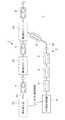
図1は、車両製造ライン1の構成を示す図である。車両製造ライン1は、メイン部品としての車体Bを車体ライン21に沿って搬送しながらこの車体Bに対し様々な部品を組み付けることにより車両を連続して生産するメインラインとしての車体組立ライン2と、車体組立ライン2において車体Bに組み付けられるサブ部品としてのドアパネルDを組み立てるサブラインとしてのドア製造ライン3と、ドア製造ライン3においてドアパネルDを組み立てるために必要な複数の小サブ部品としての複数のドア部品を供給するドア部品供給部4と、を備える。 FIG. 1 is a diagram showing a configuration of a
車体組立ライン2は、車体ライン21へ車体Bを投入する車体投入部22と、車体ライン21に沿って搬送される車体Bに対し、この車体Bの機種に応じた電気配線、内装部品、下回り部品等を予め定められた順序で組み付ける第1組付ゾーン23と、第1組付ゾーン23を通過した車体Bに対しドア製造ライン3によって組み立てられたドアパネルDを組み付ける第2組付ゾーン24と、を備える。 The vehicle
車体投入部22は、予め定められた生産計画に沿って、機種の異なる車両の車体Bを、所定のロット単位(例えば、30台)で連続して車体ライン21へ投入する。ここで生産計画とは、車両製造ライン1において生産する車両の機種の順序を定めたものである。車両製造ライン1では、N機種(Nは、2以上の整数)の異なる車両を、ロット単位で連続して生産することが可能となっている。 The vehicle
このように車体投入部22は、基本的には生産計画に沿った順序で車体Bを車体ライン21へ投入するが、何らかの理由によってこの生産計画が変更される場合がある。そこで車体投入部22は、実際に車体Bを車体ライン21へ投入した場合には、この投入した車体Bの機種や製造番号等に関する情報(以下、「AFオン確定情報」という)をドア製造ライン3及びドア部品供給部4へ通信によって送信する。第2組付ゾーン24では、車体ライン21に沿って第1組付ゾーン23から連続的に払い出される車体Bに対し、この車体Bに適したドアパネルDを組み付けられるよう、ドア製造ライン3及びドア部品供給部4では、車体投入部22から送信されるAFオン確定情報に基づいて作業を行う。 As described above, the vehicle
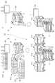
図2は、ドア製造ライン3が設けられた作業エリア30の構成を示す図である。ドア製造ライン3は、作業エリア30の天井に架設されたガイドレール31と、このガイドレール31に沿って車両一台分(例えば、4枚)のドアパネルDを搬送する複数台の搬送ユニット32と、ドア部品供給部4から搬送ユニット32と同期して払い出されるセットパック台車Cと、を備える。 FIG. 2 is a diagram showing the configuration of the
セットパック台車Cは、作業エリア30の床面Fを移動可能であり、搬送ユニット32によって搬送されるドアパネルDに組み付けられる複数のドア部品が設けられている。ドア部品供給部4は、後に図3及び図4等を参照して説明する手順に従ってセットパック台車Cを構築し、搬送ユニット32と同期した払出しサイクルタイムでセットパック台車Cを後述の払出しゲート81から払い出す。 The set pack carriage C is movable on the floor surface F of the
搬送ユニット32は、複数枚のドアパネルDを支持するドアハンガー33と、ガイドレール31に走行自在に支持された搬送装置34と、を備える。 The
搬送装置34は、ドアハンガー33が吊り下げられた本体と、ガイドレール31に摺接する複数の駆動輪と、これら駆動輪を回転駆動する駆動装置と、を備える。搬送装置34は、駆動装置によって複数の駆動輪を回転駆動することにより、本体に吊り下げられたドアハンガー33をガイドレール31の延在方向である進行方向に沿って搬送する。 The
図2に示すように、ガイドレール31は、進行方向に沿って順に、ドア部品供給部4の上方を水平方向に沿って延びる上方走行区間31aと、下方へ向けて傾斜して延びる傾斜走行区間31bと、ドア部品供給部4の前方を水平方向に沿って延びる下方走行区間31cと、に分けられる。このため搬送装置34によってガイドレール31に沿って搬送される搬送ユニット32は、傾斜走行区間31bから下方走行区間31cに至る過程で図示しない連結機構によってドア部品供給部4から払い出されるセットパック台車Cと連結する。これにより下方走行区間31cでは、搬送ユニット32はセットパック台車Cと並走する。 As shown in FIG. 2, the
以上のようなドア製造ライン3が設けられた作業エリア30において、図示しない作業者は、ガイドレール31に沿って搬送ユニット32によって搬送されるドアパネルDに対し、上述のようにこの搬送ユニット32と並走するセットパック台車Cに搭載されている複数のドア部品を組み付けるドア部品組み付け作業を行う。ドア製造ライン3において複数のドア部品が組み付けられたドアパネルDは、図1に示すように車体組立ライン2の第2組付ゾーン24に払い出される。 In the
図3は、ドア部品供給部4が設けられた作業エリア40の構成を示す図である。図3に示すように、作業エリア40は、後述の棚入工程が行われるストレージエリア6と、後述のピックアップ作業が行われるセットパックエリア7と、後述の払出し工程が行われる払出しエリア8と、に分けられる。 FIG. 3 is a diagram showing the configuration of the
ストレージエリア6は、ドア製造ライン3へセットパック台車Cを介して供給される複数のドア部品を一時的に保管する領域である。ストレージエリア6には、生産計画に基づいて外部から搬入される部品容器である複数のバケット5が荷下ろしされている。各バケット5には、それぞれドアパネルDに組み付けられる複数のドア部品が種類別に分けて納められている。ここでドア部品としては、より具体的には、スピーカ、内装パネル、パワーウインドウレギュレータ、サッシュモール、及びドアミラー等が挙げられる。また各バケット5の表面には、その内部に納められているドア部品の種類及び個数やこのドア部品が取り付けられる機種等に関する情報を、作業者が識別するためのタグ5aが貼付されている。 The
以上のような複数のバケット5は、ストレージエリア6において機種毎に分けて設けられている。各バケット群5−1,5−2,…,5−M(Mは、N以下の整数)は、それぞれ異なる機種の車両のドアパネルDに組み付けられるドア部品を収納する複数のバケット5によって構成されている。 The plurality of
またストレージエリア6には、作業者に対し棚入工程の開始及び棚入工程の内容を指示するための表示パネル60が設けられている。ここで棚入工程とは、ドア製造ライン3において車両一台分のドアパネルDに組み付けられる複数のドア部品を、予め準備されたL台(Lは、2以上の整数)の可動棚Sの各々にロット単位で種類別に設ける作業をいう。作業者は、表示パネル60に表示されている指示内容を参照することによって棚入工程を行う。より具体的には、作業者は、ストレージエリア6に設けられた複数のバケット5の中から、表示パネル60に表示されている棚入工程の内容に応じた種類及び数のバケット5を選択し、これらバケット5を可動棚Sに設け、この可動棚Sをセットパックエリア7に搬送する。これにより各々ロット単位のドア部品が設けられたL台の可動棚Sがセットパックエリア7の所定位置に搬送される。 Further, the
ところで上述のように、車体ライン21には、基本的には生産計画に沿った順序で車体Bが投入されるが、何らかの理由によってこの生産計画が変更される場合がある。したがって生産計画に沿って棚入工程を行うと、このような生産計画の変更が生じた場合には、ドア部品供給部4では適切なセットパック台車Cをドア製造ライン3へ払い出すことができず、ひいては実際に車体ライン21を流れる車体Bの機種に応じたドアパネルDを第2組付ゾーン24において組み付けることができなくなってしまう場合がある。 By the way, as described above, the vehicle body B is basically loaded into the
そこでストレージエリア6において、表示パネル60は、車体投入部22から送信されるAFオン確定情報を受信した後、すなわち実際に車体ライン21に車体Bが投入された後に、このAFオン確定情報によって特定される車体Bの機種に応じたドア部品の棚入工程の開始を指示する。 Therefore, in the
セットパックエリア7は、後述のピッキング工程を行う領域である。上述のようにセットパックエリア7には、棚入工程によって構築されたL台の可動棚S−1,S−2,S−3,S−4,…,S−Lが配置される。またセットパックエリア7には、作業者に対しピッキング工程の開始及びピッキング工程の内容を指示するための表示パネル70が設けられている。 The
ここでピッキング工程とは、L台の可動棚S−1,…,S−Lに設けられたドア部品を取り出し、車両一台分のドア部品をセットパック台車Cに積み込み、払出しエリア8に搬送する作業をいう。作業者は、表示パネル70に表示されている指示内容を参照することによってピッキング工程を行う。より具体的には、作業者は、可動棚S−1,…,S−Lの前においてセットパック台車Cを押しながら、各可動棚S−1,…,S−Lに設けられているドア部品を取り出し、セットパック台車Cに積み込む。これにより一端側の可動棚S−1から他端側の可動棚S−Lに至るまでの間に、セットパック台車Cには、車両一台分のドア部品が搭載される。 Here, the picking step is to take out the door parts provided on the L movable shelves S-1, ..., SL, load the door parts for one vehicle into the set pack trolley C, and convey them to the
また上述のように各可動棚S−1,…,S−Lには、ロット単位のドア部品が設けられている。このためこのピッキング工程を繰り返し行うことにより、ロット単位のセットパック台車Cを連続して構築することができる。 Further, as described above, each movable shelf S-1, ..., SL is provided with a door component for each lot. Therefore, by repeating this picking process, it is possible to continuously construct the set pack carriage C for each lot.
払出しエリア8は、後述の払出し工程を行う領域である。上述のようにセットパックエリア7においてピッキング工程を行うことにより、ロット単位のセットパック台車Cが連続して構築され、払出しエリア8に搬送される。また払出しエリア8には、作業者に対し払出し工程の開始及び払出し工程の内容を指示するための表示パネル80が設けられている。 The
ここで払出し工程とは、ピッキング工程によって構築されたロット単位のセットパック台車Cを、一台ずつ払出しゲート81からドア製造ライン3へ払い出す作業をいう。作業者は、表示パネル80に表示されている指示内容を参照することによって払出し工程を行う。より具体的には、作業者は、表示パネル80に表示される指示に応じて、ピッキング工程を経て構築されたセットパック台車Cを払出しゲート81へ押し出す。払出しゲート81へ押し出されたセットパック台車Cは、ガイドレール31に沿って進行する搬送ユニット32と連結され、この搬送ユニット32と並走する。 Here, the payout process means a work of paying out the set pack carts C for each lot constructed by the picking process from the
なお払出し工程において定期的にセットパック台車Cをドア製造ライン3へ払い出す際における払出しサイクルタイムは、ピッキング工程において車両一台分のドア部品をセットパック台車Cに積み込むためにかかる積込時間よりも長くすることが好ましい。このように払出しサイクルタイムと積込時間とを設定することにより、例えばピッキング工程と払出し工程とを並行して実行した場合であっても、払出しエリア8には、この払出しサイクルタイムと積込時間との差に応じた数のセットパック台車Cをストックすることができる。ドア製造ライン3へ払い出すセットパック台車Cの機種を切り替えるタイミングで可動棚S−1,…,S−Lを空にすることができるので、この空となった可動棚S−1,…,S−Lをストレージエリア6に戻し、次の機種に係る部品が設けられた複数台の可動棚をストレージエリア7に移動する時間を確保することができる。 Note that the payout cycle time when the set pack carriage C is regularly paid out to the
図4は、以上のような車体組立ライン2、ドア製造ライン3、及びドア部品供給部4における作業時間を比較した図である。なお図4では、時刻t0において車体組立ライン2の車体投入部22から車体ライン21へ、それまで車体ライン21を流れていた機種とは異なる新たな機種の車体Bが投入され、その後この車体Bが時刻t3において第2組付ゾーン24に到達した場合を示す。 FIG. 4 is a diagram comparing the working time in the vehicle
上述のようにドア部品供給部4では、時刻t0において車体投入部22からAFオン確定情報を受信した後、時刻t1において上記時刻t0のAFオン確定情報に係る機種のドア部品の棚入工程を開始する。ドア部品供給部4では、上述のように棚入工程、ピッキング工程、及び払出し工程を経て、時刻t2において上記時刻t0のAFオン確定情報に係る機種の車両1台分のドア部品を搭載したセットパック台車Cのドア製造ライン3への払出しを開始する。 As described above, the door
時刻t2以降においてドア製造ライン3では、作業者は、順次ドア部品供給部4から払い出されるセットパック台車Cに搭載されている複数のドア部品を、このセットパック台車Cと並走するドアパネルDに組み付ける組み付け作業を行う。その後時刻t3では、ドア製造ライン3では、時刻t2において初めて払い出されたセットパック台車Cに搭載された複数のドア部品が組み付けられたドアパネルDを車体組立ライン2の第2組付ゾーン24へ払い出す。またこの第2組付ゾーン24では、作業者は、上記ドア製造ライン3から払い出されるドアパネルDを、時刻t0のAFオン確定情報に係る車体Bに組み付ける。 After the time t2, in the
以上のように、第2組付ゾーン24において、ドア製造ライン3から払い出されるドアパネルDを、車体ライン21を流れる車体Bに組み付けることにより、機種の異なる車両をロット単位で連続して滞りなく生産する場合、棚入工程を開始してから、この棚入工程に係るドア部品を搭載するセットパック台車Cが初めてドア製造ライン3に払い出されるまでにかかる時間(時刻t1〜t2)と、ドア製造ライン3にセットパック台車Cが払い出されてから、このセットパック台車Cに搭載されたドア部品がドアパネルDに組み付けられ、このドアパネルDが第2組付ゾーン24に払い出されるまでにかかる時間(時刻t2〜t3)との和は、車体投入部22から車体ライン21へ車体Bが投入されてから、この車体Bが第2組付ゾーン24に到達するまでにかかる時間(時刻t0〜t3)よりも短くなるように設定される。 As described above, in the
本実施形態に係る部品供給方法によれば、以下の効果を奏する。
(1)本実施形態に係る部品供給方法では、車体組立ライン2及びドア製造ライン3によって機種の異なる車両を所定のロット単位で連続して生産する車両製造ライン1において、棚入工程、ピッキング工程、及び払出し工程を経て、ドア製造ライン3へドアパネルDを組み立てるために必要な複数のドア部品を供給する。棚入工程では、ドア部品の種類別に予め準備された複数の可動棚S−1,S−2,…,S−Lの各々にロット単位のドア部品を種類別に設け、ピッキング工程では、車両一台分のドア部品を、棚入工程を経た複数の可動棚S−1,S−2,…,S−Lから取り出しセットパック台車Cに積み込み、払出し工程では、ピッキング工程を経て構築されたセットパック台車Cをドア製造ライン3へ払い出す。以上のように本実施形態に係る部品供給方法によれば、棚入工程及びピッキング工程を経て車両一台分のセットパック台車Cを準備することにより、セットパック台車Cには、車体組立ライン2を流れる機種に応じたドア部品を過不足なく一台のセットパック台車Cに積み込むことができる。The component supply method according to this embodiment has the following effects.
(1) In the component supply method according to the present embodiment, a shelving step and a picking step are performed in the
(2)車体組立ライン2に投入される車体Bの機種の順序は、基本的には予め定められた生産計画に沿ったものとなっているため、セットパック台車Cにドア部品を積み込む作業も基本的には生産計画に沿ったものとなる。しかしながら実際には、車体組立ライン2に投入される車体Bの機種の順序は、様々な理由により直前に変更される場合がある。このため車体組立ライン2における生産計画の変更に対し流動的に対応できるように、セットパック台車Cにドア部品を積み込む作業を行う必要がある。このような生産計画の変更に対応するための1つの方法として、棚入工程では、生産計画に基づいて近い将来においてセットパック台車Cに積み込まれる機種のドア部品の他、生産計画の変更に対応できるように他の機種のドア部品も可動棚Sに設けておくことが考えられる。しかしながらこの場合、可動棚Sを大量に準備する必要がある。これに対し本実施形態に係る部品供給方法において、棚入工程では、実際に車体組立ライン2へ車体Bが投入された後に開始する。これにより、車体組立ライン2において生産計画の変更があった場合であっても、車体組立ライン2を実際に流れる車体Bの機種に応じたドア部品を積み込んだセットパック台車Cを準備できる。また本実施形態に係る部品供給方法によれば、生産計画の変更に対応するために可動棚Sを大量に準備する必要がないので、可動棚Sを設置するエリアを最小限にすることができる。 (2) Since the order of the models of the vehicle body B to be put into the vehicle
(3)本実施形態に係る部品供給方法において、払出し工程において定期的にセットパック台車Cをドア製造ライン3へ払い出す際における払出しサイクルタイムは、ピッキング工程において車両一台分のドア部品をセットパック台車Cに積み込むためにかかる積込時間よりも長い。これにより、ドア製造ライン3へ払い出すセットパック台車Cの機種を切り替えるタイミングで可動棚S−1,S−2,…,S−Lを空にし、この空となった可動棚S−1,S−2,…,S−Lと、次の機種のドア部品を設けた棚とを交換する時間を確保することができる。 (3) In the component supply method according to the present embodiment, the payout cycle time when the set pack cart C is periodically paid out to the
以上、本発明の一実施形態について説明したが、本発明はこれに限らない。本発明の趣旨の範囲内で、細部の構成を適宜変更してもよい。 Although one embodiment of the present invention has been described above, the present invention is not limited to this. The detailed configuration may be appropriately changed within the scope of the gist of the present invention.
1…車両製造ライン
2…車体組立ライン(メインライン)
23…第1組付ゾーン
24…第2組付ゾーン
B…車体(メイン部品)
3…ドア製造ライン(サブライン)
D…ドアパネル(サブ部品)
4…ドア部品供給部
6…ストレージエリア
7…セットパックエリア7
S,S−1,S−2,…,S−L…可動棚
C…セットパック台車(台車)
8…払出しエリア1 ...
23 ...
3 ... Door manufacturing line (sub line)
D: Door panel (sub part)
4 ... Door parts supply
S, S-1, S-2, ..., SL ... Movable shelves C ... Set pack carts (carts)
8 ... Dispensing area
Claims (3)
Translated fromJapanese複数の棚の各々に前記ロット単位の小サブ部品を種類別に設ける棚入工程と、
車両一台分の小サブ部品を前記複数の棚から取り出し台車に積み込むピッキング工程と、
前記台車を前記サブラインへ払い出す払出し工程と、を備えることを特徴とする部品供給方法。In a vehicle manufacturing line that continuously manufactures vehicles of different models in a predetermined lot unit by assembling the sub parts assembled in the sub line to the main parts in the main line, a plurality of units necessary for assembling the sub parts in the sub line Is a parts supply method for supplying small sub-parts of
A shelving step of providing each of the plurality of shelves with small sub-parts for each lot by type,
A picking process of taking out small sub-parts for one vehicle from the plurality of shelves and loading them on a trolley,
And a payout step of paying out the dolly to the sub-line.
Priority Applications (2)
| Application Number | Priority Date | Filing Date | Title |
|---|---|---|---|
| JP2018199241AJP6723315B2 (en) | 2018-10-23 | 2018-10-23 | Parts supply method |
| CN201910982442.3ACN111086574B (en) | 2018-10-23 | 2019-10-15 | Parts supply method |
Applications Claiming Priority (1)
| Application Number | Priority Date | Filing Date | Title |
|---|---|---|---|
| JP2018199241AJP6723315B2 (en) | 2018-10-23 | 2018-10-23 | Parts supply method |
Publications (2)
| Publication Number | Publication Date |
|---|---|
| JP2020066078Atrue JP2020066078A (en) | 2020-04-30 |
| JP6723315B2 JP6723315B2 (en) | 2020-07-15 |
Family
ID=70389199
Family Applications (1)
| Application Number | Title | Priority Date | Filing Date |
|---|---|---|---|
| JP2018199241AExpired - Fee RelatedJP6723315B2 (en) | 2018-10-23 | 2018-10-23 | Parts supply method |
Country Status (2)
| Country | Link |
|---|---|
| JP (1) | JP6723315B2 (en) |
| CN (1) | CN111086574B (en) |
Cited By (2)
| Publication number | Priority date | Publication date | Assignee | Title |
|---|---|---|---|---|
| CN112596473A (en)* | 2020-11-20 | 2021-04-02 | 首钢京唐钢铁联合有限责任公司 | Hot-dip plate production control method and device |
| DE112021002136T5 (en) | 2020-04-01 | 2023-06-01 | Koa Corporation | Alloy for a resistor and use of a resistor alloy in a resistor |
Citations (4)
| Publication number | Priority date | Publication date | Assignee | Title |
|---|---|---|---|---|
| JPH02284835A (en)* | 1989-04-25 | 1990-11-22 | Mazda Motor Corp | Work assembly system |
| JP2005238353A (en)* | 2004-02-24 | 2005-09-08 | Honda Motor Co Ltd | How to assemble a motorcycle |
| JP2007216340A (en)* | 2006-02-17 | 2007-08-30 | Nissan Motor Co Ltd | Component supply system and component supply method |
| JP2011110636A (en)* | 2009-11-25 | 2011-06-09 | Daihatsu Motor Co Ltd | Automobile assembling facility |
Family Cites Families (6)
| Publication number | Priority date | Publication date | Assignee | Title |
|---|---|---|---|---|
| JP2000015530A (en)* | 1998-07-02 | 2000-01-18 | Nissan Motor Co Ltd | Synchro production instruction system for vehicle production line |
| JP3879968B2 (en)* | 2000-09-21 | 2007-02-14 | 本田技研工業株式会社 | Vehicle assembly system and vehicle assembly method |
| JP4033394B2 (en)* | 2003-05-27 | 2008-01-16 | ダイハツ工業株式会社 | Production instruction equipment for production line equipment and method for configuring the same |
| JP4851855B2 (en)* | 2006-06-09 | 2012-01-11 | 株式会社日立製作所 | Work results collection system |
| JP6443264B2 (en)* | 2015-08-12 | 2018-12-26 | 株式会社ダイフク | Goods storage equipment |
| DE102018000790A1 (en)* | 2018-02-01 | 2018-08-02 | Daimler Ag | Picking station for components for mounting a vehicle and method for equipping a driverless transport vehicle for transferring components into a mounting area of a vehicle |
- 2018
- 2018-10-23JPJP2018199241Apatent/JP6723315B2/ennot_activeExpired - Fee Related
- 2019
- 2019-10-15CNCN201910982442.3Apatent/CN111086574B/enactiveActive
Patent Citations (4)
| Publication number | Priority date | Publication date | Assignee | Title |
|---|---|---|---|---|
| JPH02284835A (en)* | 1989-04-25 | 1990-11-22 | Mazda Motor Corp | Work assembly system |
| JP2005238353A (en)* | 2004-02-24 | 2005-09-08 | Honda Motor Co Ltd | How to assemble a motorcycle |
| JP2007216340A (en)* | 2006-02-17 | 2007-08-30 | Nissan Motor Co Ltd | Component supply system and component supply method |
| JP2011110636A (en)* | 2009-11-25 | 2011-06-09 | Daihatsu Motor Co Ltd | Automobile assembling facility |
Cited By (2)
| Publication number | Priority date | Publication date | Assignee | Title |
|---|---|---|---|---|
| DE112021002136T5 (en) | 2020-04-01 | 2023-06-01 | Koa Corporation | Alloy for a resistor and use of a resistor alloy in a resistor |
| CN112596473A (en)* | 2020-11-20 | 2021-04-02 | 首钢京唐钢铁联合有限责任公司 | Hot-dip plate production control method and device |
Also Published As
| Publication number | Publication date |
|---|---|
| CN111086574B (en) | 2022-07-15 |
| JP6723315B2 (en) | 2020-07-15 |
| CN111086574A (en) | 2020-05-01 |
Similar Documents
| Publication | Publication Date | Title |
|---|---|---|
| US12319502B2 (en) | Order fulfillment system | |
| CN102730099B (en) | Vehicle body assembling line and vehicle body assembling method | |
| US8311905B1 (en) | Computerized system and method for automated demand-based parts delivery | |
| JP6849604B2 (en) | How and equipment to store or remove goods | |
| JP6723315B2 (en) | Parts supply method | |
| KR101940608B1 (en) | Picking system and picking method | |
| CN106470919B (en) | Sorting system and sorting method | |
| JP5641338B2 (en) | Picking method | |
| WO2016178347A1 (en) | Automated warehouse and suspension-type stacker crane | |
| CN105270797A (en) | Article storage facility and method of operating same | |
| US12030420B2 (en) | Package storage and delivery unit | |
| CN112543946B (en) | Improved storage and sorting system and sorting method for transferring goods between two storage areas | |
| CN110325462B (en) | Automatic storage and retrieval system and method for operating the same | |
| JP4983272B2 (en) | Picking equipment | |
| WO1999044751A1 (en) | Coating equipment | |
| JP2010061260A (en) | Physical distribution optimization support system | |
| WO2019187036A1 (en) | Component mounting system | |
| CN104787566A (en) | Trolley conveying device | |
| WO2019229880A1 (en) | Component replenishment management system and component mounting system | |
| JP2005044099A (en) | Parts supplying system, controller, and control method | |
| JP2016210547A (en) | Picking system | |
| CN214267441U (en) | A side-opening intelligent mobile warehouse | |
| JPH08197352A (en) | Parts assembly line and assembly method | |
| US20190248587A1 (en) | Method for operating a conveyor system | |
| CN110366531A (en) | Automated storage and retrieval system |
Legal Events
| Date | Code | Title | Description |
|---|---|---|---|
| A621 | Written request for application examination | Free format text:JAPANESE INTERMEDIATE CODE: A621 Effective date:20190531 | |
| A977 | Report on retrieval | Free format text:JAPANESE INTERMEDIATE CODE: A971007 Effective date:20200210 | |
| A131 | Notification of reasons for refusal | Free format text:JAPANESE INTERMEDIATE CODE: A131 Effective date:20200303 | |
| A521 | Request for written amendment filed | Free format text:JAPANESE INTERMEDIATE CODE: A523 Effective date:20200501 | |
| TRDD | Decision of grant or rejection written | ||
| A01 | Written decision to grant a patent or to grant a registration (utility model) | Free format text:JAPANESE INTERMEDIATE CODE: A01 Effective date:20200609 | |
| A61 | First payment of annual fees (during grant procedure) | Free format text:JAPANESE INTERMEDIATE CODE: A61 Effective date:20200623 | |
| R150 | Certificate of patent or registration of utility model | Ref document number:6723315 Country of ref document:JP Free format text:JAPANESE INTERMEDIATE CODE: R150 | |
| LAPS | Cancellation because of no payment of annual fees |