JP2020058758A - Chair and manufacturing method of the same - Google Patents
Chair and manufacturing method of the sameDownload PDFInfo
- Publication number
- JP2020058758A JP2020058758AJP2018210901AJP2018210901AJP2020058758AJP 2020058758 AJP2020058758 AJP 2020058758AJP 2018210901 AJP2018210901 AJP 2018210901AJP 2018210901 AJP2018210901 AJP 2018210901AJP 2020058758 AJP2020058758 AJP 2020058758A
- Authority
- JP
- Japan
- Prior art keywords
- backrest
- tilting frame
- lock body
- base body
- chair
- Prior art date
- Legal status (The legal status is an assumption and is not a legal conclusion. Google has not performed a legal analysis and makes no representation as to the accuracy of the status listed.)
- Granted
Links
Images


Landscapes
- Chair Legs, Seat Parts, And Backrests (AREA)
- Chairs Characterized By Structure (AREA)
Abstract
Translated fromJapaneseDescription
Translated fromJapanese本願発明は、背もたれがばね手段に抗して後傾するロッキング椅子とその製造方法に関するものである。 The present invention relates to a rocking chair in which a backrest tilts backwards against spring means and a method for manufacturing the rocking chair.
背もたれが後傾するロッキング式椅子において、背もたれの後傾姿勢を制御するロック装置(傾動制御装置)を設けることは、広く行われている。ロック装置の構造は様々であるが、特許文献1には、ベース体に後傾動自在に連結された背支桿(傾動フレーム)の前端に、前面に係合溝が上下多段に形成されたロック部材受け(受動ロック体)を取り付ける一方、ベース体には、ロック部材受けにおける任意の段の係合溝に係脱するロック部材(可動ロック体)を前後スライド自在に装着して、レバー操作によってロック部材を動かす構成が開示されている。 BACKGROUND ART In a rocking type chair in which a backrest tilts backward, it is widely practiced to provide a lock device (tilt control device) for controlling the backrest posture of the backrest. Although there are various structures of the lock device, in
特許文献1のように、係合溝が上下多段に形成されたロック受け部材を使用すると、ロック受け部材をコンパクト化できるため、ロック装置全体としてもコンパクト化できる利点がある。 When the lock receiving member having the engaging grooves formed in the upper and lower stages is used as in
さて、背もたれがばね手段に抗して後傾するロッキング椅子において、着座した人が背もたれにもたれ掛かってから初めてばね手段が加圧されると、ばね手段が無負荷状態から変形し始めるため、着座した人がもたれ掛かると、背もたれが急速に後傾する現象を生じて、使用者に大きな不安感を与えてしまう。 Now, in a rocking chair in which the backrest leans backwards against the spring means, if the spring means is pressurized only after the seated person leans against the backrest, the spring means begins to deform from the unloaded state, so that the seating When a person who leans back leans on the backrest, a phenomenon in which the backrest tilts backward rapidly occurs, which gives a great sense of anxiety to the user.
そこで、ロッキング椅子では、着座した人が背もたれにもたれ掛かっていない基準姿勢(ニュートラル状態)でもばね手段を予め加圧(与圧)しておくことにより、背もたれの後傾動に対して初期抵抗(プリテンション)を付与して、以て、背もたれが急激に後傾する現象を防止している。従って、背もたれは、基準姿勢においてばね手段によって前傾方向に付勢されており、ストッパー手段によって基準姿勢を保持している。 Therefore, in the rocking chair, the spring means is pre-pressurized (pressurized) even in a standard posture (neutral state) in which the seated person is not leaning against the backrest, so that the initial resistance (pre-tension) to the back tilting of the backrest is reduced. Tension) is applied to prevent the backrest from suddenly leaning backward. Therefore, the backrest is biased in the forward tilt direction by the spring means in the reference posture, and is held in the reference posture by the stopper means.
そして、ロッキング椅子の組み工程では、ばね手段を予圧した状態で部材を組み付ける工程が必要であるが、ばね手段の弾性復元力はかなり強いため、ばね手段を予圧した状態で部材を組み付ける工程が厄介であった。特許文献1においても同様であり、ばね手段を与圧した状態で背支桿をピンでベース体や座に連結する作業を行わねばならないため、椅子の組み立て作業は非常に厄介になると思われる。 Further, in the assembling process of the rocking chair, it is necessary to assemble the members with the spring means preloaded, but since the elastic restoring force of the spring means is quite strong, the process of assembling the members with the spring means preloaded is troublesome. Met. The same is true for
本願発明は、このような現状を改善すべく成されたものである。 The present invention has been made to improve the present situation.
本願発明は、椅子とその製法を含んでおり、椅子は、
「脚支柱の上端に固定されたベース体と、ばね手段に抗して後傾動するように前記ベース体に連結された傾動フレームと、前記傾動フレームに取付けられた背もたれとを有しており、
前記背もたれは、人がもたれ掛かっていない基準姿勢においても、与圧された前記ばね手段によって前傾方向に付勢されている一方、
前記傾動フレームには、前記背もたれが基準姿勢のときに前記ばね手段によって付勢された状態でベース体に当たる規制部材を設けている」
という基本構成なっている。The present invention includes a chair and its manufacturing method.
`` Having a base body fixed to the upper ends of the leg columns, a tilting frame connected to the base body so as to tilt backwards against the spring means, and a backrest attached to the tilting frame,
The backrest is biased in the forward leaning direction by the pressurized spring means even in a reference posture in which a person is not leaning back,
The tilting frame is provided with a restricting member that abuts the base body while being urged by the spring means when the backrest is in the standard posture. "
It has a basic configuration.
そして、特許文献1の発明では、上記基本構成において、
「前記規制部材は、前記傾動フレームをベース体に連結した後に取付け可能であり、前記傾動フレームには、前記規制部材の取付け部が、前記ベース体の外側に露出するように形成されている」
という構成になっている。And in the invention of
"The regulation member can be attached after connecting the tilting frame to the base body, and the attachment portion of the regulation member is formed on the tilting frame so as to be exposed to the outside of the base body."
It is configured as.
請求項2の発明は請求項1の展開例であり、請求項1において、
「前記規制部材は、前記ベース体の後ろに配置された前面に複数の係合部が上下多段に形成された受動ロック体になっている一方、
前記ベース体の後部に、レバー操作によって前記受動ロック体の任意の係合部に係脱する可動ロック体が配置されており、
前記受動ロック体は、前記傾動フレームに設けた下向き開口のロック受け凹所に下方から嵌め込まれていてボルトで前記傾動フレームに固定されており、かつ、前記受動ロック体に、前記背もたれが基準姿勢のときに前記ベース体に下方から当たって前記背もたれを基準姿勢に保持するストッパー部を設けている」
という構成になっている。The invention of
"The restriction member is a passive lock body in which a plurality of engaging portions are formed in a vertical multistage on a front surface arranged behind the base body,
On the rear part of the base body, a movable lock body that is engaged and disengaged with an arbitrary engaging portion of the passive lock body by a lever operation is arranged.
The passive lock body is fitted from below into a lock receiving recess of a downward opening provided in the tilting frame and is fixed to the tilting frame by a bolt, and the passive lock body has the backrest in a standard posture. At this time, a stopper portion is provided for hitting the base body from below and holding the backrest in the standard posture. "
It is configured as.
更に、請求項2の展開例として、請求項3では、
「前記受動ロック体のストッパー部は、前記係合部が形成されているエリアの左右両側においてフランジ状に張り出している」
という構成になっている。Further, as a development example of
"The stopper portion of the passive lock body projects like a flange on the left and right sides of the area where the engagement portion is formed."
It is configured as.
椅子の製法は、請求項4で特定している。すなわちこの製法は、請求項1〜3のうちのいずれかに記載した椅子の製造方法であって、
「前記規制部材は取付けられておらずに前記傾動フレームが前記ベース体に連結された工程の後に、前記傾動フレームを前記ばね手段に抗して後傾させた状態で、前記規制部材を前記傾動フレームにボルトによって固定する工程を有している」
という特徴を有している。The manufacturing method of the chair is specified in
"After the step of connecting the tilting frame to the base body without attaching the restricting member, the tilting frame is tilted backward against the spring means to tilt the restricting member. It has a process of fixing it to the frame with bolts. "
It has the feature of.
本願発明では、規制部材は、傾動フレームをベース体に連結してから傾動フレームに取り付けることができる。従って、規制部材を傾動フレームに取り付けると、ばね手段は予圧された状態になって、背もたれは、基準姿勢において前傾方向に付勢された状態になって、使用者は安心して背もたれにもたれ掛かることができる。 In the present invention, the regulating member can be attached to the tilting frame after connecting the tilting frame to the base body. Therefore, when the regulating member is attached to the tilting frame, the spring means is in a preloaded state, and the backrest is biased in the forward tilting direction in the reference posture, and the user leans on the backrest in comfort. be able to.
特に、請求項4の製法を採用すると、背もたれをばね手段に抗して後傾させた状態で規制部材を傾動フレームに固定できるため、規制部材は、ばね手段の弾性力が全く掛かっていない状態で、ボルトによって傾動フレームに容易に固定できる。従って、請求項4の構成を採用すると、背もたれにプリテンションが掛かけられた椅子を、製造が容易な状態で提供することができる。 In particular, when the manufacturing method according to
規制部材はストッパー機能のみを有することも可能であるが、請求項2のように規制部材を受動ロック体に利用すると、規制部材を利用して背もたれの傾動ロックを行えるため、背もたれを所定の姿勢にロックできる椅子でありながら、構造をできるだけ簡単化できる。 The restricting member may have only a stopper function, but when the restricting member is used as the passive lock body as in
請求項3の構成を採用すると、受動ロック体のストッパー部は係合部を設けたエリアの左右両側に形成されているため、ストッパー部は、両端支持の状態で荷重を支持できる。従って、弾性復元力をバランス良く受けることができると共に、ストッパー部の支持強度も向上できる。 When the structure of
次に、本願発明の実施形態を図面に基づいて説明する。以下では、方向を特定するため前後・左右の文言を使用するが、この方向は普通に着座した人から見た状態を基準にしている。正面視方向は、着座した人と対抗した方向である。 Next, an embodiment of the present invention will be described with reference to the drawings. In the following, front and rear and left and right words are used to specify the direction, but this direction is based on the state as seen by a person who normally sits down. The front view direction is the direction facing the seated person.
(1).椅子の概要
まず、本実施形態の肘掛け装置が適用された椅子の概要を説明する。この椅子は、オフィス等で多用されている回転椅子であり、主要部材として、座1と背もたれ2、背もたれ2が取り付けられたバックフレーム3、及びキャスタ付きの脚装置4を備えている。背もたれ2は、樹脂製の背板の表裏両面にクッションを張ってこれを袋状の表皮材で覆った構造になっているが、背板しか表示していない。椅子は、オプション品として、肘掛け装置6とヘッドレスト(或いはショルダーレスト)7を備えている。(1). Outline of Chair First, an outline of a chair to which the armrest device of the present embodiment is applied will be described. This chair is a swivel chair that is frequently used in offices and the like, and includes a
バックフレーム3は、左右中間部に位置した背支柱8と、背支柱8の上端に取り付けた左右長手のアッパサポート9と、背支柱8の下端から左右に張り出したロアサポート10とを備えており、背もたれ2は、アッパサポート9の左右両端及びロアサポート10の左右両端に連結されている。従って、背もたれ2は、4点支持の状態でバックフレーム3に連結されている。 The
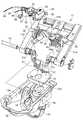
図3(B)に示すように、バックフレーム3の下端には前向き部3aが一体に形成されており、前向き部3aに固定された傾動フレーム11が、脚装置4の状態に固定されたベース体12に後傾動可能に連結されている。 As shown in FIG. 3B, a forward facing
図4(A)や図5に示すように、ベース体12は金属板製で上向きに開口した形態であり、後部に形成された段部12bにリアブラケット13を固定し、段部12bとリアブラケット13とに固定されたブッシュ14に、脚支柱(ガスシリンダ)15の上端部が嵌着されている。 As shown in FIG. 4 (A) and FIG. 5, the
図4(A)や図5に示すように、傾動フレーム11は、前後に長い左右の側枠部11aと、左右の側枠部11aの後部に一体に繋がったジョイント11bとを有しており、左右の側枠部11aの前端部に、軸受け部11cを内向きに突設して、左右の軸受け部11cに、ばね手段の受け部となるプッシャー17が一体に繋がっている。 As shown in FIGS. 4 (A) and 5, the tilting
軸受け部11cは、ベース体12に設けた下向き凹部18に下方から入り込んでおり、この状態で、左右の軸受け部11cとベース体12とが支軸16によって連結されている。従って、傾動フレーム11及び背もたれ2は、支軸16を中心にして後傾動する。また、プッシャー17は、手前に向けて低くなるように傾斜姿勢になっており、図9にも示すように、ベース体12の底部に設けた透かし穴19(図5も参照)から、ベース体12の内部に向かっている。プッシャー17は、ベース体12に装着したカバー20によって、下方から覆われている。 The bearing
図3(B)に示すように、バックフレーム3における前向き部3aの前端には、左右の鉤部3cが形成されている。一方、傾動フレーム11におけるジョイント部11bには、鉤部3cが嵌まる凹部(図示せず)を形成しており、前向き部3aとジョイント部11bとは、上下に噛み合った状態で、ボルト(図示せず)によって締結されている。なお、バックフレーム3と傾動フレーム11とを一体に形成することも可能であるし、傾動フレーム11に背アウターシェルを固定するといったことも可能である。 As shown in FIG. 3B, left and right hooks 3c are formed at the front end of the
(2).ばねユニット
図4(A)から理解できるように、ベース体12の前半部に、コイルスプリングが内蔵されたばねケース22が、後ろに向けて低くなる傾斜姿勢で配置されている。また、ベース体12の側板12aとばねケース22との間にはリンク23が配置されており、リンク23の後端部は、傾動フレーム11の側枠部11aに設けた軸受け部11cに連結されている一方、リンク23の前端部は、ばねケース22に横向き突設したボス25に連結されている。(2). Spring Unit As can be understood from FIG. 4 (A), the
更に、図5や図9に示すように、ばねケース22の内部に設けたばね受けスライダー26をばねケース22の後面から後ろ向きに突設して、ばね受けスライダー26の後端が、支軸16に設けたプッシャー17に当接している。従って、着座した人が背もたれ2にもたれ掛かって背もたれ2が後傾すると、プッシャー17によってばね受けスライダー26が押されてばねが押し縮められる。これにより、背もたれ2の後傾動に対する弾性的な抵抗が付与される。 Further, as shown in FIG. 5 and FIG. 9, a
図9に明示するように、プッシャー17の後面17aは手前に向けて凹んだ凹面になっており、ばね受けスライダー26の後端(頂点)が上下方向に移動すると、支軸16からばね受けスライダー26の後端までのスパンが変化して、傾動フレーム11の後傾動に対する抵抗が変化する。そこで、図5に示すように、ベース体12の側板12aに回転自在に保持したハンドル27に、ばねケース22に上から当接する周面カム28を固定して、ハンドル27によって周面カム28を回転操作することにより、ロッキングに対する抵抗の大きさを変更できるようにしている。 As clearly shown in FIG. 9, the rear surface 17a of the
リンク23とばねケース22と間には、前端部をばねケース22のボス25に連結した姿勢保持体29が配置されている。姿勢保持体29は、周面カム28を常にばねケース22に当接した状態に保持するためのものであり、姿勢保持体29により、ハンドル27を正逆いずれの方向に回転させても、周面カム28は常にばねケース22に当接した状態に保持されて、ばねケース22の姿勢を変更できる。 Between the
そして、着座した人が背もたれ2にもたれていないニュートラル姿勢でも、ばね受けスライダー26はコイルばねを加圧しており、傾動フレーム11には、ある程度の弾性復元力が作用している。 Even when the seated person does not lean on the
図4に示すように、リンク23の前端部には外向きのフランジ23aが形成されていて、フランジ23aはベース体12の上面にビス(図示せず)で固定されている。また、図3から理解できるように、左右のリンク23のフランジ23aにはそれぞれガイドレール30がビスで固定されており、ガイドレール30に、図2に示す座アウターシェル31が前後スライド可能で上向き抜け不能に保持されている。座1は、座アウターシェル31に取付けられている。 As shown in FIG. 4, an
座アウターシェル31の後部は、傾動フレーム11のジョイント部11bに連結されている。すなわち、例えば図3や図4(A)に示すように、傾動フレーム11におけるジョイント部11b部の左右両端部に突起部32を設けて、突起部32に左右外向きに突出した支軸部33を形成しており、支軸部33に、座アウターシェル31の後部が、図4に示す連結キャップ34を介して連結されている。従って、背もたれ2が後傾すると、座1は、背もたれ2に連動して小さい角度で後傾しつつ後退する。 The rear portion of the seat
(3).昇降制御装置
図4,5を参照して説明したように、ベース体12の後半部に形成した段部12bにリアブラケット13が固定されているが、図3,5から理解できるように、リアブラケット13の上面に制御ユニット板35を固定しており、この制御ユニット板35に、脚支柱15のプッシュバルブ15a(図8参照)を押す高さ調節ユニットと、背もたれ2の傾動を制御するためのロックユニットとを設けている。(3). Lifting control device As described with reference to FIGS. 4 and 5, the
制御ユニット板35は、図示しないビスによってリアブラケット13に固定されている。また、図8に示すように、制御ユニット板35には、リアブラケット13と係合する鉤状等の位置決め係合部36を設けている。 The
高さ調節ユニットとしては、例えば図7(A)に示すように、制御ユニット板35に、平面視において前後長手線及び左右長手線に対して傾斜した姿勢でかつ上向きに開口した樋状の第1ガイド部37を設け、第1ガイド部37に、プッシュバルブ15aを下向きに押す回動式のリンク杆(図示せず)を装着している。リンク杆は、図5に示す第1ワイヤー38によって回動操作される。 As the height adjusting unit, for example, as shown in FIG. 7 (A), a gutter-shaped first unit that is opened upward in the
第1ワイヤー38は第1チューブ39に挿通されており、第1チューブ39の一端部は、第1ガイド部37の前端部に設けた壁板37aのU溝40に係止されている。また、図示は省略するが、第1ワイヤー38の一端にはボールが取付けられており、ボールは、リンク杆の一端に係止されている。そして、第1ワイヤー38が図示しない第1操作レバーによって引き操作されると、リンク杆が回動して脚支柱15のプッシュバルブ15aが押される。これにより、脚支柱15はロックが解除されて、座1の高さを調節することができる。 The
(4).ロック装置(傾動制御装置)の基本構造
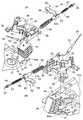
例えば図7に示すように、ロック装置の一環として、制御ユニット板35の下面に、平板状の可動ロック体41が前後動可能に装着されている。一方、例えば図5に示すように、傾動フレーム11におけるジョイント11bのうちか左右中間部に、前方及び下方に開口したロック受け凹所42が形成されていて、このロック受け凹所42に、前面に係合溝43が多段(5段)に形成されたブロック状の受動ロック体44を嵌め込んで固定している。(4). Basic Structure of Lock Device (Tilt Control Device) For example, as shown in FIG. 7, as a part of the lock device, a flat plate-shaped
そして、可動ロック体41の後端部が受動ロック体44の任意の係合溝43に嵌まり込むと、背もたれ2は傾動不能に保持される。可動ロック体41の後端部が受動ロック体44から外れた状態では、背もたれ2は後傾動自在である。受動ロック体44は請求項に記載した規制部材の例であり、ロック受け凹所42は、規制部材の取付け部の一例である。 Then, when the rear end portion of the
可動ロック体41は、図5以下に示す第2ワイヤー45によって回動操作される。以下、各部位を詳述する。 The
図7(B)に明示するように、制御ユニット板35の後部には、後ろ向きに開口した角形の切り開き部46を形成していると共に、制御ユニット板35の下面に、可動ロック体41が前後動自在に嵌まる凹部47を形成している。凹部47は切り開き部46よりも左右両側に広がっている。 As clearly shown in FIG. 7B, a rearward opening of the
そして、受動ロック体44は可動ロック体41の後ろに配置されているが、図8(A)(B)に示すように、切り開き部46に後ろから入り込んでいる。従って、可動ロック体41が後ろ方向に後退すると、可動ロック体41が受動ロック体44における任意の係合溝43に嵌入して、背もたれ2は傾動不能なロック状態に保持され、可動ロック体41が前進しきった状態では、受動ロック体44は上下回動自在となって、背もたれ2は、傾動自在なフリー状態になる。 The
図9,10に明示するように、受動ロック体44は、傾動フレーム11のジョイント11bにボルト(ビス)48で固定されている。また、受動ロック体44の上面に設けた位置決め突起49が、傾動フレーム11のジョイント11bに形成された位置決め穴50に嵌入している。 9 and 10, the
更に、例えば図5,6に示すように、受動ロック体44のうち前寄り部位の下端に、フランジ状に張り出した左右のストッパー部44aを設けており、図7(C)に示すように、ストッパー部44aは、リアブラケット13の後端部に設けた左右の受け部51に下方から当接可能になっている。図5に示すように、リアブラケット13の受け部51は後ろ向きに突出した状態になっている。 Further, as shown in FIGS. 5 and 6, for example, left and
既述のとおり、背もたれ2は、着座した人がもたれ掛かっていないニュートラル姿勢において、ばね手段によってプリテンションが掛けられている。従って、背もたれ2は常に前向き回動する方向に付勢されているが、受動ロック体44のストッパー部44aがリアブラケット13の受け部51に下方から当たることにより、背もたれ2の前向き回動姿勢が規制されて、背もたれ2はニュートラル姿勢に保持されている。 As described above, the
(5).可動ロック体41のスライド制御機構
図7に示すように、制御ユニット板35には、前後方向に移動自在なスライダー52が配置されている。スライダー52は、制御ユニット板35の左側部に位置して前半部を小径部53aと成した筒部53と、筒部53から横向き(右向き)に張り出したアーム部54とを備えており、筒部53は、傾動フレーム11の左側部に設けた筒状の第2ガイド部55に後ろからスライド自在に嵌まっている。(5). Slide Control Mechanism of
他方、アーム部54の先端には下向きのボス56を設けており、ボス56は制御ユニット板35に形成された前後長手の長穴57に挿通されており、ボス56の下端面に可動ロック体41がビス58で固定されている。制御ユニット板35はリアブラケット13の上面に重なっているので、可動ロック体41は、制御ユニット板35とリアブラケット13との間に介在している。そこで、図9(図5も参照)に示すように、リアブラケット13には、ビス58の頭が前後スライド自在に嵌まる逃がし穴59が形成されている。 On the other hand, a downwardly directed
可動ロック体41はスライダー52と一体に前後動すると共に、スライダー52を介して、制御ユニット板35に前後スライド自在で離脱不能に保持されている。また、図7に示すとおり、アーム部54のうち筒部53に近い部位に、底面視長方形のガイド片60を下向きに突設している一方、制御ユニット板35には、ガイド片60が前後スライド自在に嵌まるガイド溝61を形成している。従って、スライダー52は、こじれがない状態で前後スライドする。 The
図8に示すように、第2ワイヤー45は第2チューブ62に挿通されており、第2ワイヤー45の一端部は、制御ユニット板35の前端に設けた受け板63に保持されている。この場合、第2ワイヤー45の一端部は、後ろに行くに従って低くなるように傾斜している。従って、受け板63も、側面視において鉛直線に対して傾斜している。 As shown in FIG. 8, the
第2ワイヤー45の一端部(項端部)は、第2ガイド部55とスライダー52の筒部53とを貫通して後ろ向きに延びており、後端にはボール64を固定している。そして、第2ガイド部55に、スライダー52を後ろ向きに付勢する大径ばね65と、スライダー52を前向きに付勢する小径ばね66とを内蔵している。大径ばね65は、筒部53の小径部53aに被嵌しており、小径ばね66は、筒状のばね受け67で後ろから支持されており、ばね受け67はボール64で支持されている。大径ばね65の弾性力は、小径ばね66の弾性力よりも強くなっている。 One end (end portion) of the
第2ワイヤー45の他端は、図示しない第2操作レバーに連結されている。そして、第2操作レバーを操作していない状態では、第2ワイヤー45は、2つのばね65,66を圧縮させた状態で引かれており、従って、可動ロック体41は前進したフリー状態になっている。 The other end of the
他方、第2操作レバーをフリー姿勢からロック姿勢に引くと、大径ばね65によってスライダー52が後ろ向きに押される。従って、可動ロック体41の真後ろに受動ロック体44の係合溝43が位置している場合は、可動ロック体41はそのまま係合溝43に嵌合して、背もたれ2は傾動不能に保持される。 On the other hand, when the second operating lever is pulled from the free posture to the locked posture, the
背もたれ2の姿勢によっては、可動ロック体41の真後ろに係合溝43が位置していない状態も有り得るが、この場合は、第2操作レバーをロック状態にすると、可動ロック体41がいったん受動ロック体44の前面に当接して、大径ばね65は殆ど伸び変形せずに、第2ワイヤー45は小径ばね66によって後退し、次いで、着座した人が身体を手前に起こして背もたれ2が前傾すると、可動ロック体41の真後ろに係合溝43が位置した時点で、大径ばね65が伸長して可動ロック体41が後退する。これにより、背もたれ2は傾動不能なロック状態に移行する。 Depending on the posture of the
第2操作レバーをロック姿勢からフリー姿勢に切り換えたとき、可動ロック体41と係合溝43との間に摩擦がある場合は、使用者は身体で少し背もたれ2を押すなどして摩擦を無くすことにより、可動ロック体41は第2ワイヤー45の引き作用によってスライダー52を前進させることができる(着座した人が背もたれ2にもたれていない状態で背もたれ2が前傾すると危険であるので、ロック状態からフリー状態への移行は、着座した人の身体が背もたれ2に当たっている状態で行うべきである。)。 When there is friction between the
(6).組み立て手順・まとめ
既述のとおり、背もたれ2は、着座した人の負荷が掛かっていないニュートラル姿勢でも、ばねによる弾性復元力が作用しており、このため、背もたれ2は前傾方向に付勢されている。従って、受動ロック体44のストッパー部44aには、下向きの付勢力が作用している。(6) .Assembly procedure / summary As described above, the
そして、椅子の組み立てに際しては、ばね受けスライダー26を前進させきった状態で行うのが安全であり、従って、背もたれ2の組み付けなどを終えてから、最後に受動ロック体44を取り付けることが合理的である。 When assembling the chair, it is safe to perform it with the
この場合、受動ロック体44を取付けていない状態では、背もたれ2は使用時の基準姿勢(ニュートラル姿勢)よりも前向きに回動しており、ボルト48を受動ロック体44にねじ込んでいって、受動ロック体44を傾動フレーム11のジョイント11bに引き付けると、背もたれ2はニュートラル姿勢に向けて回動(後傾)していく。しかし、この方法では、ボルト48のねじ込みに手間が掛かるため、非能率的である。 In this case, when the
これに対しては、図10に示すように、背もたれ2又はバックフレーム3の上端部に手を当てて後ろに押して、背もたれ2をニュートラル姿勢よりも後傾させた状態で、受動ロック体44をボルト48で固定することにより、受動ロック体44の取付けを、作業者に負担を掛けることなく、簡単かつ正確に行うことができる。 On the other hand, as shown in FIG. 10, by pushing the
上記のとおり、受動ロック体44の取付けは、背もたれ2をバックフレーム3に取り付けた後で行ってもよいし、背もたれ2をバックフレーム3に取り付ける前に行ってもよい。いずれにしても、ばねケース22に内蔵されたロッキングばねに対して大きなモーメントを作用させて、傾動フレーム11を簡単に後傾させることができるため、受動ロック体44の取付けを簡単かつ正確に行える(位置決め突起49と位置決め穴50との嵌め合わせも容易に行える。)。 As described above, the
なお、ニュートラル姿勢において、受動ロック体44のストッパー部44aには下向きの押圧力が作用しているが、この力はさほど強くはないため、ボルト48に対する負担は小さい。従って、安全上の問題はない。 In the neutral posture, a downward pressing force acts on the
他方、ロック状態では、着座した人の押圧力が背もたれ2に掛かっている状態では、可動ロック体41は受動ロック体44によって下向きに押されるが、可動ロック体41はリアブラケット13で支持されるため、着座した人の押圧力は的確に支持される。 On the other hand, in the locked state, the
他方、ロック状態では、着座した人の押圧力が背もたれ2に掛かっていない状態では、可動ロック体41は、ばねケース22に内蔵したばねの弾性復元力によって上向きに押されるが、可動ロック体41は制御ユニット板35によって上から支えられているため、安全である。制御ユニット板35も、位置決め係合部36によって上向き離脱不能に保持されているため、可動ロック体41を安定的に支持できる。 On the other hand, in the locked state, the
実施形態のように制御ユニット板35を使用すると、高さ調節ユニットとロックユニットとを精度良く組み付けることができる利点がある。また、受動ロック体44を制御ユニット板35の切り開き部46に部分的に配置すると、可動ロック体41の後端部が、係合溝43の左右両側方においてリアブラケット13又は制御ユニット板35で支持されるため、強度を格段に向上できる。 When the
以上、本願発明の実施形態を説明したが、本願発明は、他にも様々に具体化できる。例えば、ベースや傾動フレームの具体的な構造は、様々に変更可能である。背もたれの後傾動に抵抗を付与するばね手段としては、板ばねやトーションバーなどの各種のばね体を採用できる。背もたれも、任意の構造に設定できる。 Although the embodiments of the present invention have been described above, the present invention can be embodied in various other ways. For example, the specific structures of the base and the tilting frame can be changed in various ways. Various spring bodies such as a leaf spring and a torsion bar can be adopted as the spring means for giving resistance to the rearward tilting of the backrest. The backrest can also be set to any structure.
実施形態では、規制部材の一例として、前面に係合溝を多段に形成した受動ロック体を採用したが、規制部材は、必ずしもロック機能を有する必要はないし、ロック機能を有する場合でも、実施形態とは異なる係合手段を採用できる。 In the embodiment, as an example of the restricting member, a passive lock body in which engaging grooves are formed in multiple stages on the front surface is adopted, but the restricting member does not necessarily have the lock function, and even when the restricting member has the lock function, the embodiment Different engagement means can be adopted.
また、規制部材がロック機能を有するか否かにかかわらず、規制部材は、傾動フレームに対して、後ろから装着したり横方向から装着したりすることも可能である。従って、傾動フレームに設ける規制部材取付け部は、後ろ向きに露出させたり、左右方向の外向きに露出させたりすることが可能である。後ろ向きや横向きに露出させる場合、トンネル状に形成すると、規制部材の支持機能に優れているため好適である。 Further, regardless of whether or not the regulating member has a locking function, the regulating member can be mounted to the tilting frame from the rear or the lateral direction. Therefore, the restricting member attachment portion provided on the tilting frame can be exposed rearward or outward in the left-right direction. In the case of exposing it backward or sideways, it is preferable to form it in a tunnel shape because it has an excellent function of supporting the regulating member.
本願発明は、椅子に具体化できる。従って、産業上利用できる。 The present invention can be embodied in a chair. Therefore, it can be used industrially.
1 座
2 背もたれ
3 バックフレーム
11 傾動フレーム
12 ベース体
13 リアブラケット
35 制御ユニット板
41 可動ロック体
42 規制部材の取付け部の一例としてのロック受け凹所
43 係合部の一例としての係合溝
44 規制部材の一例としての受動ロック体
44a フランジ状のストッパー部
45 可動ロック体を制御する第2ワイヤー
48 ボルト
52 スライダー
55 第2ガイド部
56 ボス
57 長穴
58 ビスDESCRIPTION OF
Claims (4)
Translated fromJapanese前記背もたれは、人がもたれ掛かっていない基準姿勢においても、与圧された前記ばね手段によって前傾方向に付勢されている一方、
前記傾動フレームには、前記背もたれが基準姿勢のときに前記ばね手段によって付勢された状態でベース体に当たる規制部材を設けている構成であって、
前記規制部材は、前記傾動フレームをベース体に連結した後に取付け可能であり、前記傾動フレームには、前記規制部材の取付け部が、前記ベース体の外側に露出するように形成されている、
椅子。It has a base body fixed to the upper ends of the leg columns, a tilting frame connected to the base body so as to tilt backwards against the spring means, and a backrest attached to the tilting frame,
The backrest is biased in the forward leaning direction by the pressurized spring means even in a reference posture in which a person is not leaning back,
The tilting frame is provided with a restricting member that comes into contact with the base body in a state of being biased by the spring means when the backrest is in the reference posture,
The restricting member can be attached after connecting the tilting frame to the base body, and the tilting frame is formed with an attaching portion of the restricting member exposed to the outside of the base body.
Chair.
前記ベース体の後部に、レバー操作によって前記受動ロック体の任意の係合部に係脱する可動ロック体が配置されており、
前記受動ロック体は、前記傾動フレームに設けた下向き開口のロック受け凹所に下方から嵌め込まれていてボルトで前記傾動フレームに固定されており、かつ、前記受動ロック体に、前記背もたれが基準姿勢のときに前記ベース体に下方から当たって前記背もたれを基準姿勢に保持するストッパー部を設けている、
請求項1に記載した椅子。While the restriction member is a passive lock body in which a plurality of engaging portions are formed in a vertical multistage on a front surface arranged behind the base body,
On the rear part of the base body, a movable lock body that is engaged and disengaged with an arbitrary engaging portion of the passive lock body by a lever operation is arranged.
The passive lock body is fitted from below into a lock receiving recess of a downward opening provided in the tilting frame and is fixed to the tilting frame by a bolt, and the passive lock body has the backrest in a standard posture. At this time, a stopper portion is provided for holding the backrest in a standard posture by hitting the base body from below.
The chair according to claim 1.
請求項2に記載した椅子。The stopper portion of the passive lock body projects like a flange on both left and right sides of an area where the engagement portion is formed,
The chair according to claim 2.
前記規制部材は取付けられておらずに前記傾動フレームが前記ベース体に連結された工程の後に、前記傾動フレームを前記ばね手段に抗して後傾させた状態で、前記規制部材を前記傾動フレームにボルトによって固定する工程を有している、
椅子の製造方法。It is a manufacturing method of the chair according to any one of claims 1 to 3,
After the step of connecting the tilting frame to the base body without attaching the restricting member, the restricting member is moved to the tilting frame while being tilted backward against the spring means. Has a step of fixing with bolts,
Chair manufacturing method.
Applications Claiming Priority (2)
| Application Number | Priority Date | Filing Date | Title |
|---|---|---|---|
| JP2018190577 | 2018-10-09 | ||
| JP2018190577 | 2018-10-09 |
Publications (2)
| Publication Number | Publication Date |
|---|---|
| JP2020058758Atrue JP2020058758A (en) | 2020-04-16 |
| JP7208766B2 JP7208766B2 (en) | 2023-01-19 |
Family
ID=70219814
Family Applications (10)
| Application Number | Title | Priority Date | Filing Date |
|---|---|---|---|
| JP2018210901AActiveJP7208766B2 (en) | 2018-10-09 | 2018-11-08 | Chair and its manufacturing method |
| JP2018210909AActiveJP7295628B2 (en) | 2018-10-09 | 2018-11-08 | Chair and its armrest device |
| JP2018210903AActiveJP7198051B2 (en) | 2018-10-09 | 2018-11-08 | Chair |
| JP2018210904AActiveJP7190334B2 (en) | 2018-10-09 | 2018-11-08 | Chair |
| JP2018210905AActiveJP7169166B2 (en) | 2018-10-09 | 2018-11-08 | Chair |
| JP2018210906AActiveJP7252738B2 (en) | 2018-10-09 | 2018-11-08 | chair back |
| JP2018210907AActiveJP7295627B2 (en) | 2018-10-09 | 2018-11-08 | Chair |
| JP2018210902AActiveJP7307537B2 (en) | 2018-10-09 | 2018-11-08 | Chair |
| JP2018210908AActiveJP7579045B2 (en) | 2018-10-09 | 2018-11-08 | Chair arm rest device |
| JP2018220651AActiveJP7414394B2 (en) | 2018-10-09 | 2018-11-26 | Chair |
Family Applications After (9)
| Application Number | Title | Priority Date | Filing Date |
|---|---|---|---|
| JP2018210909AActiveJP7295628B2 (en) | 2018-10-09 | 2018-11-08 | Chair and its armrest device |
| JP2018210903AActiveJP7198051B2 (en) | 2018-10-09 | 2018-11-08 | Chair |
| JP2018210904AActiveJP7190334B2 (en) | 2018-10-09 | 2018-11-08 | Chair |
| JP2018210905AActiveJP7169166B2 (en) | 2018-10-09 | 2018-11-08 | Chair |
| JP2018210906AActiveJP7252738B2 (en) | 2018-10-09 | 2018-11-08 | chair back |
| JP2018210907AActiveJP7295627B2 (en) | 2018-10-09 | 2018-11-08 | Chair |
| JP2018210902AActiveJP7307537B2 (en) | 2018-10-09 | 2018-11-08 | Chair |
| JP2018210908AActiveJP7579045B2 (en) | 2018-10-09 | 2018-11-08 | Chair arm rest device |
| JP2018220651AActiveJP7414394B2 (en) | 2018-10-09 | 2018-11-26 | Chair |
Country Status (1)
| Country | Link |
|---|---|
| JP (10) | JP7208766B2 (en) |
Families Citing this family (4)
| Publication number | Priority date | Publication date | Assignee | Title |
|---|---|---|---|---|
| JP2023056839A (en)* | 2021-10-08 | 2023-04-20 | パナソニックIpマネジメント株式会社 | bathroom chair |
| JP2023073034A (en)* | 2021-11-15 | 2023-05-25 | 株式会社イトーキ | chair and its back |
| KR102468455B1 (en)* | 2022-07-26 | 2022-11-18 | 신명수 | Lumbar Support Device for Chair with Height Adjustment |
| NO348525B1 (en)* | 2022-12-14 | 2025-03-03 | Sapdesign As | An adjustment device for a chair backrest |
Citations (4)
| Publication number | Priority date | Publication date | Assignee | Title |
|---|---|---|---|---|
| JPH11276287A (en)* | 1998-03-30 | 1999-10-12 | Takano Co Ltd | Locking device |
| KR20010025368A (en)* | 2000-10-04 | 2001-04-06 | 이준구 | A frame for chair |
| US20070040433A1 (en)* | 2005-08-19 | 2007-02-22 | Chien-Kai Huang | Chair adjustable device |
| JP2017079943A (en)* | 2015-10-26 | 2017-05-18 | タカノ株式会社 | Lock mechanism and chair |
Family Cites Families (36)
| Publication number | Priority date | Publication date | Assignee | Title |
|---|---|---|---|---|
| JPS60140454U (en)* | 1984-02-29 | 1985-09-17 | 池田物産株式会社 | vehicle seat |
| JPS6368115A (en)* | 1986-09-11 | 1988-03-28 | 東京シ−ト株式会社 | Armrest of seat for vehicle |
| JPH0475205U (en)* | 1990-11-13 | 1992-06-30 | ||
| KR100334315B1 (en)* | 1992-06-15 | 2002-10-11 | 헤르만밀러인코퍼레이티드 | Slope control device for office |
| JPH0767746A (en)* | 1993-08-31 | 1995-03-14 | Fuji Kiko Co Ltd | Vehicle seat with armrest |
| JP3132961B2 (en)* | 1994-06-16 | 2001-02-05 | 株式会社岡村製作所 | Chair backrest vertical adjustment device |
| JPH0840120A (en)* | 1994-07-27 | 1996-02-13 | Ikeda Bussan Co Ltd | Rear seat for vehicle |
| JP3482842B2 (en)* | 1997-11-06 | 2004-01-06 | 株式会社イトーキクレビオ | Interlocking device between chair seat and backrest |
| JP3595953B2 (en) | 1998-07-09 | 2004-12-02 | 株式会社イトーキクレビオ | Chair seat or backrest |
| WO2000022959A1 (en)* | 1998-10-20 | 2000-04-27 | Protoned B.V. | Chair mechanism |
| JP4316748B2 (en)* | 1999-11-08 | 2009-08-19 | 株式会社岡村製作所 | Chair |
| JP2001204582A (en) | 2000-01-31 | 2001-07-31 | Itoki Crebio Corp | Armrest device |
| GB0114581D0 (en) | 2001-06-14 | 2001-08-08 | White Adam | Twister seat |
| US7014269B2 (en)* | 2001-06-15 | 2006-03-21 | Hon Technology Inc. | Chair back construction |
| JP4189455B2 (en)* | 2002-01-31 | 2008-12-03 | 株式会社岡村製作所 | Chair tension structure |
| JP2003299548A (en)* | 2002-02-08 | 2003-10-21 | Koyo Giken Kk | Arm rest mechanism and furniture with arm rest containing the same |
| US20050062323A1 (en) | 2003-06-11 | 2005-03-24 | Dicks Gerald G. | Chair |
| JP4183084B2 (en)* | 2003-11-21 | 2008-11-19 | 株式会社イトーキ | Chair and its back |
| JP4652767B2 (en) | 2004-10-13 | 2011-03-16 | 株式会社岡村製作所 | Tensioning structure for upholstery for chair backrest, etc. |
| JP2006314437A (en) | 2005-05-11 | 2006-11-24 | T S Tec Kk | Vehicle seat |
| CA2665176C (en)* | 2006-10-04 | 2016-01-19 | Formway Furniture Limited | A back portion for a chair with a moveable upper section |
| US20080093908A1 (en) | 2006-10-19 | 2008-04-24 | Cooley Gordon D | Moveable Armrest |
| KR100982797B1 (en)* | 2008-02-26 | 2010-09-16 | 정해일 | Car Headrests |
| TWM340761U (en) | 2008-04-11 | 2008-09-21 | zheng-hong Lin | Mesh chair frame, and its assembly structure |
| JP4913185B2 (en) | 2009-08-07 | 2012-04-11 | 株式会社岡村製作所 | Chair elbow frame mounting structure |
| JP6041479B2 (en)* | 2011-11-16 | 2016-12-07 | 株式会社イトーキ | Chair back and method of manufacturing the same |
| MY169026A (en) | 2012-09-20 | 2019-02-04 | Steelcase Inc | Chair arm assembly |
| WO2014061732A1 (en)* | 2012-10-18 | 2014-04-24 | 株式会社岡村製作所 | Chair |
| JP6140419B2 (en)* | 2012-10-18 | 2017-05-31 | 株式会社岡村製作所 | Lumber support and chair |
| CN105263367A (en)* | 2013-06-06 | 2016-01-20 | 株式会社伊藤喜 | Chair |
| JP6518073B2 (en) | 2014-11-07 | 2019-05-22 | 株式会社イトーキ | Chair |
| JP6352785B2 (en)* | 2014-11-28 | 2018-07-04 | 株式会社タチエス | Seat device |
| JP6678417B2 (en) | 2015-09-25 | 2020-04-08 | 株式会社オカムラ | Furniture sheets, furniture surface components and furniture |
| DE102016105751A1 (en)* | 2016-03-30 | 2017-10-05 | Bock 1 Gmbh & Co. Kg | Height-adjustable armrest |
| US10477973B2 (en)* | 2016-11-01 | 2019-11-19 | Ergogenesis Workplace Solutions, Llc | Ergonomic chair |
| JP6876409B2 (en)* | 2016-11-04 | 2021-05-26 | 株式会社イトーキ | Chair back |
- 2018
- 2018-11-08JPJP2018210901Apatent/JP7208766B2/enactiveActive
- 2018-11-08JPJP2018210909Apatent/JP7295628B2/enactiveActive
- 2018-11-08JPJP2018210903Apatent/JP7198051B2/enactiveActive
- 2018-11-08JPJP2018210904Apatent/JP7190334B2/enactiveActive
- 2018-11-08JPJP2018210905Apatent/JP7169166B2/enactiveActive
- 2018-11-08JPJP2018210906Apatent/JP7252738B2/enactiveActive
- 2018-11-08JPJP2018210907Apatent/JP7295627B2/enactiveActive
- 2018-11-08JPJP2018210902Apatent/JP7307537B2/enactiveActive
- 2018-11-08JPJP2018210908Apatent/JP7579045B2/enactiveActive
- 2018-11-26JPJP2018220651Apatent/JP7414394B2/enactiveActive
Patent Citations (4)
| Publication number | Priority date | Publication date | Assignee | Title |
|---|---|---|---|---|
| JPH11276287A (en)* | 1998-03-30 | 1999-10-12 | Takano Co Ltd | Locking device |
| KR20010025368A (en)* | 2000-10-04 | 2001-04-06 | 이준구 | A frame for chair |
| US20070040433A1 (en)* | 2005-08-19 | 2007-02-22 | Chien-Kai Huang | Chair adjustable device |
| JP2017079943A (en)* | 2015-10-26 | 2017-05-18 | タカノ株式会社 | Lock mechanism and chair |
Also Published As
| Publication number | Publication date |
|---|---|
| JP7190334B2 (en) | 2022-12-15 |
| JP2020058759A (en) | 2020-04-16 |
| JP7307537B2 (en) | 2023-07-12 |
| JP7579045B2 (en) | 2024-11-07 |
| JP2020058765A (en) | 2020-04-16 |
| JP2020058766A (en) | 2020-04-16 |
| JP2020058764A (en) | 2020-04-16 |
| JP2020058760A (en) | 2020-04-16 |
| JP2020058763A (en) | 2020-04-16 |
| JP7295628B2 (en) | 2023-06-21 |
| JP7198051B2 (en) | 2022-12-28 |
| JP2020058762A (en) | 2020-04-16 |
| JP7169166B2 (en) | 2022-11-10 |
| JP2020058761A (en) | 2020-04-16 |
| JP7414394B2 (en) | 2024-01-16 |
| JP2020058769A (en) | 2020-04-16 |
| JP7295627B2 (en) | 2023-06-21 |
| JP7208766B2 (en) | 2023-01-19 |
| JP7252738B2 (en) | 2023-04-05 |
Similar Documents
| Publication | Publication Date | Title |
|---|---|---|
| US6213552B1 (en) | Multi-position chair control mechanism for synchronously adjusting the seat and backrest of a chair | |
| US5464274A (en) | Chair seat tilt adjustment and locking mechanism | |
| US8297701B2 (en) | Reclining chair with enhanced adjustability | |
| JP2020058758A (en) | Chair and manufacturing method of the same | |
| US5267777A (en) | Resilient chair support | |
| JPH0243481B2 (en) | ||
| JPS5949802B2 (en) | ergonomic chair | |
| US20100109402A1 (en) | Locking device for a movable member in a chair | |
| WO2006119209A2 (en) | Chair with recline control mechanism, recline limit control and back tilt mechanism | |
| US20060097554A1 (en) | Chair with backrest depth adjustment mechanism | |
| JP3359862B2 (en) | Locking device | |
| US11160377B2 (en) | Synchronous chair mechanism and chair having same | |
| JP2004049717A (en) | Device for inclining backrest or the like for chair | |
| JP2004049655A (en) | Seat forward and backward sliding device for chair | |
| JP3998222B2 (en) | Chair support mechanism | |
| JP2011115570A (en) | Rocking chair | |
| JP4773801B2 (en) | Locking mechanism of the locking device | |
| JP7469860B2 (en) | Chair | |
| JP2003310377A (en) | Gas spring for chair | |
| JP3637731B2 (en) | Chair armrest device | |
| JP4750535B2 (en) | Backrest locking device in reclining chair | |
| JP5989999B2 (en) | Chair | |
| JP3637732B2 (en) | Chair armrest device | |
| JP3616971B2 (en) | Chair backrest tilt shock absorber | |
| JP6478394B2 (en) | Chair |
Legal Events
| Date | Code | Title | Description |
|---|---|---|---|
| A621 | Written request for application examination | Free format text:JAPANESE INTERMEDIATE CODE: A621 Effective date:20211027 | |
| A977 | Report on retrieval | Free format text:JAPANESE INTERMEDIATE CODE: A971007 Effective date:20220916 | |
| A131 | Notification of reasons for refusal | Free format text:JAPANESE INTERMEDIATE CODE: A131 Effective date:20220928 | |
| A521 | Request for written amendment filed | Free format text:JAPANESE INTERMEDIATE CODE: A523 Effective date:20221115 | |
| TRDD | Decision of grant or rejection written | ||
| A01 | Written decision to grant a patent or to grant a registration (utility model) | Free format text:JAPANESE INTERMEDIATE CODE: A01 Effective date:20221207 | |
| A61 | First payment of annual fees (during grant procedure) | Free format text:JAPANESE INTERMEDIATE CODE: A61 Effective date:20230106 | |
| R150 | Certificate of patent or registration of utility model | Ref document number:7208766 Country of ref document:JP Free format text:JAPANESE INTERMEDIATE CODE: R150 |