JP2020044869A - Front grille for vehicle - Google Patents
Front grille for vehicleDownload PDFInfo
- Publication number
- JP2020044869A JP2020044869AJP2018172409AJP2018172409AJP2020044869AJP 2020044869 AJP2020044869 AJP 2020044869AJP 2018172409 AJP2018172409 AJP 2018172409AJP 2018172409 AJP2018172409 AJP 2018172409AJP 2020044869 AJP2020044869 AJP 2020044869A
- Authority
- JP
- Japan
- Prior art keywords
- millimeter wave
- grill
- millimeter
- wave transmitting
- heating element
- Prior art date
- Legal status (The legal status is an assumption and is not a legal conclusion. Google has not performed a legal analysis and makes no representation as to the accuracy of the status listed.)
- Granted
Links
- 238000010438heat treatmentMethods0.000claimsabstractdescription67
- 239000000463materialSubstances0.000claimsdescription35
- 239000011347resinSubstances0.000claimsdescription18
- 229920005989resinPolymers0.000claimsdescription18
- 239000000758substrateSubstances0.000claimsdescription2
- 230000005540biological transmissionEffects0.000abstractdescription25
- 238000013016dampingMethods0.000abstract1
- 239000002184metalSubstances0.000description10
- 229910052751metalInorganic materials0.000description10
- 238000004519manufacturing processMethods0.000description9
- 230000000694effectsEffects0.000description5
- 238000000034methodMethods0.000description5
- 239000000155meltSubstances0.000description4
- 239000004417polycarbonateSubstances0.000description4
- 238000001514detection methodMethods0.000description3
- 238000002834transmittanceMethods0.000description3
- 230000002238attenuated effectEffects0.000description2
- 238000005034decorationMethods0.000description2
- 238000012986modificationMethods0.000description2
- 230000004048modificationEffects0.000description2
- 229920003229poly(methyl methacrylate)Polymers0.000description2
- 239000004926polymethyl methacrylateSubstances0.000description2
- 238000004544sputter depositionMethods0.000description2
- 238000007740vapor depositionMethods0.000description2
- OKTJSMMVPCPJKN-UHFFFAOYSA-NCarbonChemical compound[C]OKTJSMMVPCPJKN-UHFFFAOYSA-N0.000description1
- 229910001111Fine metalInorganic materials0.000description1
- BQCADISMDOOEFD-UHFFFAOYSA-NSilverChemical compound[Ag]BQCADISMDOOEFD-UHFFFAOYSA-N0.000description1
- 230000003044adaptive effectEffects0.000description1
- 230000015572biosynthetic processEffects0.000description1
- 230000000903blocking effectEffects0.000description1
- 229910052799carbonInorganic materials0.000description1
- 238000005260corrosionMethods0.000description1
- 230000007797corrosionEffects0.000description1
- 230000007423decreaseEffects0.000description1
- 238000010586diagramMethods0.000description1
- 229910052738indiumInorganic materials0.000description1
- APFVFJFRJDLVQX-UHFFFAOYSA-Nindium atomChemical compound[In]APFVFJFRJDLVQX-UHFFFAOYSA-N0.000description1
- AMGQUBHHOARCQH-UHFFFAOYSA-Nindium;oxotinChemical compound[In].[Sn]=OAMGQUBHHOARCQH-UHFFFAOYSA-N0.000description1
- 239000002932lusterSubstances0.000description1
- 238000002844meltingMethods0.000description1
- 230000008018meltingEffects0.000description1
- 239000007769metal materialSubstances0.000description1
- 239000002923metal particleSubstances0.000description1
- 229910001120nichromeInorganic materials0.000description1
- 238000010422paintingMethods0.000description1
- 229920005668polycarbonate resinPolymers0.000description1
- 238000003825pressingMethods0.000description1
- 229910052709silverInorganic materials0.000description1
- 239000004332silverSubstances0.000description1
Images


Landscapes
- Radar Systems Or Details Thereof (AREA)
- Surface Heating Bodies (AREA)
- Laminated Bodies (AREA)
- Vehicle Waterproofing, Decoration, And Sanitation Devices (AREA)
Abstract
Description
Translated fromJapanese本発明は、ミリ波レーダ装置が搭載された車両において、そのミリ波レーダ装置よりも前側に配置される車両用フロントグリルに関する。 The present invention relates to a vehicle front grille disposed on a front side of a millimeter wave radar device in a vehicle equipped with the millimeter wave radar device.
フロントグリルの後側にミリ波レーダ装置が搭載された車両では、フロントグリルの骨格部分がグリル本体によって構成される。グリル本体の一部であってミリ波レーダ装置の前方となる箇所は、ミリ波透過性を有するミリ波透過部によって構成される(例えば、特許文献1参照)。そして、ミリ波レーダ装置から、ミリ波が前方へ送信されると、そのミリ波はミリ波透過部を透過した後に、先行車両、歩行者等を含む車外の対象物に当たって反射される。反射されたミリ波は、ミリ波透過部を透過してミリ波レーダ装置によって受信される。ミリ波レーダ装置は、送信及び受信されたミリ波に基づき、車両と上記対象物との距離や相対速度を検出する。 In a vehicle in which the millimeter wave radar device is mounted on the rear side of the front grill, the skeleton of the front grill is constituted by the grill main body. A part of the grill main body, which is located in front of the millimeter-wave radar device, is configured by a millimeter-wave transmitting portion having millimeter-wave transparency (for example, see Patent Document 1). Then, when the millimeter wave is transmitted forward from the millimeter wave radar device, the millimeter wave is transmitted through the millimeter wave transmitting portion and then is reflected by an object outside the vehicle including a preceding vehicle, a pedestrian, and the like. The reflected millimeter wave passes through the millimeter wave transmitting unit and is received by the millimeter wave radar device. The millimeter wave radar device detects a distance and a relative speed between the vehicle and the object based on the transmitted and received millimeter waves.
ところで、フロントグリルのミリ波透過部に雪が付着すると、ミリ波が減衰され、ミリ波レーダ装置の検出性能が低下するおそれがある。ところが、上記特許文献1を含む従来のフロントグリルでは、雪によるミリ波の減衰を抑制する対策が特に講じられていない。 By the way, if snow adheres to the millimeter wave transmitting portion of the front grill, the millimeter waves are attenuated, and the detection performance of the millimeter wave radar device may be reduced. However, in the conventional front grille including the above-mentioned Patent Literature 1, no measure is specifically taken to suppress the attenuation of millimeter waves due to snow.
本発明は、このような実情に鑑みてなされたものであって、その目的は、雪によるミリ波の減衰を抑制することのできる車両用フロントグリルを提供することにある。 The present invention has been made in view of such circumstances, and an object of the present invention is to provide a vehicle front grill that can suppress the attenuation of millimeter waves due to snow.
上記課題を解決する車両用フロントグリルは、ミリ波を前方へ送信するとともに反射されたミリ波を受信するミリ波レーダ装置が搭載された車両において、同ミリ波レーダ装置よりも前側に配置されるグリル本体を骨格部分として備え、前記グリル本体の一部であって前記ミリ波レーダ装置の前方となる箇所は、ミリ波透過性を有するミリ波透過部により構成され、前記ミリ波透過部の前面及び後面の一方には、通電により発熱するヒータ線を有するとともにミリ波透過性を有する発熱体が固定されている。 A vehicle front grill that solves the above-described problem is disposed on a front side of the millimeter wave radar device in a vehicle equipped with a millimeter wave radar device that transmits a millimeter wave forward and receives a reflected millimeter wave. A grill main body is provided as a skeleton portion, and a part of the grill main body and in front of the millimeter wave radar device is configured by a millimeter wave transmitting portion having a millimeter wave transmitting property, and a front surface of the millimeter wave transmitting portion. On one of the rear surface and the rear surface, a heating element having a heater wire that generates heat when energized and having a millimeter wave transmission property is fixed.
上記の構成によれば、ミリ波レーダ装置から前方へミリ波が送信されると、そのミリ波は、フロントグリルのうち、ミリ波レーダ装置の前方のミリ波透過部及び発熱体を透過する。先行車両、歩行者等を含む車外の対象物に当たって反射されたミリ波は、上記送信されたミリ波と同様にミリ波透過部及び発熱体を透過し、ミリ波レーダ装置によって受信される。ミリ波レーダ装置では、送信及び受信されたミリ波により、車両と対象物との距離や相対速度が検出される。 According to the above configuration, when a millimeter wave is transmitted forward from the millimeter wave radar device, the millimeter wave transmits through the millimeter wave transmitting portion and the heating element in front of the millimeter wave radar device in the front grill. Millimeter waves reflected on an object outside the vehicle, including a preceding vehicle, a pedestrian, etc., are transmitted through the millimeter wave transmitting portion and the heating element in the same manner as the transmitted millimeter waves, and are received by the millimeter wave radar device. In the millimeter wave radar device, the distance and the relative speed between the vehicle and the target are detected based on the transmitted and received millimeter waves.
また、ヒータ線は、通電されると発熱する。
従って、発熱体がミリ波透過部の前面に固定されている場合に、その発熱体に雪が付着しても、ヒータ線が通電されることで発熱すれば、その熱により雪が溶かされ、雪によるミリ波の減衰が抑制される。The heater wire generates heat when energized.
Therefore, when the heating element is fixed to the front surface of the millimeter wave transmitting portion, even if snow adheres to the heating element, if heat is generated by energizing the heater wire, the heat melts the snow and the snow melts. Millimeter wave attenuation is suppressed.
また、発熱体がミリ波透過部の後面に固定されている場合に、そのミリ波透過部の前面に雪が付着しても、ヒータ線が通電されることで発熱すれば、その熱により雪が溶かされ、雪によるミリ波の減衰が抑制される。 Also, when the heating element is fixed to the rear surface of the millimeter wave transmitting portion, even if snow adheres to the front surface of the millimeter wave transmitting portion, if the heater wire generates heat when energized, the heat melts the snow. As a result, the attenuation of millimeter waves due to snow is suppressed.
上記車両用フロントグリルにおいて、前記グリル本体の少なくとも前記ミリ波透過部は、透明な樹脂材料により形成された基材と、前記基材の後面に形成された加飾層とを備えていることが好ましい。 In the vehicle front grill, at least the millimeter wave transmitting portion of the grill main body may include a base material formed of a transparent resin material, and a decorative layer formed on a rear surface of the base material. preferable.
上記の構成によれば、フロントグリルを車両前方から見た場合、ミリ波透過部では、透明な基材を通して、同基材の後面に形成された加飾層が見える。表現を変えると、透明な基材の前面から後方へ奥まった箇所に加飾層が位置するように見える。このようにして、加飾層によってミリ波透過部が装飾される。 According to the above configuration, when the front grill is viewed from the front of the vehicle, the decorative layer formed on the rear surface of the transparent substrate is visible in the millimeter wave transmitting portion. In other words, the decorative layer appears to be located at a position that is recessed backward from the front of the transparent base material. Thus, the millimeter wave transmitting portion is decorated by the decorative layer.
また、ミリ波透過部の加飾層は、それよりも後側に位置するミリ波レーダ装置を隠す機能を発揮する。そのため、車両の前方からミリ波レーダ装置が見えることが抑制される。
上記車両用フロントグリルにおいて、前後方向における前記ミリ波透過部の厚みをTとし、ミリ波の波長をλeとし、前記基材の比誘電率をεpとし、整数をnとするとき、前記ミリ波透過部の全体について、前記厚みTが次式 T={(λe/2)/√(εp)}n を満たす値に設定されていることが好ましい。In addition, the decorative layer of the millimeter wave transmitting portion has a function of hiding the millimeter wave radar device located on the rear side. Therefore, the millimeter wave radar device is suppressed from being seen from the front of the vehicle.
In the vehicle front grill, when the thickness of the millimeter wave transmitting portion in the front-rear direction is T, the wavelength of the millimeter wave is λe, the relative permittivity of the base material is εp, and the integer is n, the millimeter wave It is preferable that the thickness T is set to a value that satisfies the following expression T = {(λe / 2) / √ (εp)} n for the entire transmission portion.
ミリ波透過部の全体について、厚みTが上記の式を満たす値に設定されることで、ミリ波がミリ波透過部を透過する際に生ずる減衰量が、上記式を満たさない場合よりも少なくされる。 By setting the thickness T to a value that satisfies the above equation for the entire millimeter-wave transmitting section, the amount of attenuation that occurs when the millimeter wave transmits through the millimeter-wave transmitting section is less than when the above equation is not satisfied. Is done.
上記車両用フロントグリルにおいて、前記発熱体は、樹脂材料により形成され、かつ前記ヒータ線を前後両側から挟み込む一対のシートをさらに備えており、前記発熱体は、一方の前記シートにおいて前記ミリ波透過部の前面及び後面の一方に固定されていることが好ましい。 In the vehicle front grill, the heating element further includes a pair of sheets formed of a resin material and sandwiching the heater wire from both front and rear sides, and the heating element transmits the millimeter wave through one of the sheets. It is preferably fixed to one of the front and rear surfaces of the part.
上記の構成によれば、発熱体の一方のシートがミリ波透過部の前面及び後面の一方に固定されることで、ヒータ線が所定の配線パターンで、ミリ波透過部の前側及び後側の一方に配置される。 According to the above configuration, one sheet of the heating element is fixed to one of the front surface and the rear surface of the millimeter wave transmitting portion, so that the heater wire has a predetermined wiring pattern, and the front and rear sides of the millimeter wave transmitting portion are formed. Placed on one side.
また、ミリ波レーダ装置から送信されたミリ波、及び車外の対象物に当たって反射されたミリ波は、発熱体では、例えばヒータ線の設けられていない箇所を透過する。
上記車両用フロントグリルにおいて、前記グリル本体には、エンブレムを取り付けるための取り付け孔が形成されており、前記ミリ波透過部は前記取り付け孔から離間した箇所に形成されていることが好ましい。In addition, the millimeter wave transmitted from the millimeter wave radar device and the millimeter wave reflected on an object outside the vehicle pass through, for example, a portion of the heating element where no heater wire is provided.
In the above-described vehicle front grill, it is preferable that a mounting hole for mounting an emblem is formed in the grill main body, and the millimeter wave transmitting portion is formed at a position separated from the mounting hole.
上記の構成によれば、グリル本体では、ミリ波の透過がミリ波透過部において行われる。そのため、グリル本体において、ミリ波透過部とは異なる箇所には、ミリ波の透過性が要求されない。該当する箇所には、取り付け孔が含まれる。取り付け孔においてグリル本体に取り付けられるエンブレムについても、ミリ波の透過性が要求されない。従って、エンブレム及び取り付け孔は、ミリ波を透過させる役割とは異なる役割、例えば、発光部、電気車両における充電ポート等の設置箇所となるといった役割を担うことで、フロントグリルの多機能化を図ることが可能となる。 According to the above configuration, in the grill main body, the transmission of the millimeter wave is performed in the millimeter wave transmission portion. Therefore, in the grill main body, a portion different from the millimeter-wave transmitting portion is not required to have millimeter-wave transmittance. Applicable locations include mounting holes. The emblem attached to the grill main body in the attachment hole is not required to have millimeter wave transparency. Therefore, the emblem and the mounting hole play a role different from the role of transmitting the millimeter wave, for example, a role of providing a light emitting unit, a charging port in an electric vehicle, and the like, thereby realizing a multifunctional front grill. It becomes possible.
上記車両用フロントグリルによれば、雪によるミリ波の減衰を抑制することができる。 According to the vehicle front grill, the attenuation of millimeter waves due to snow can be suppressed.
以下、車両用フロントグリルを具体化した一実施形態について図1〜図3を参照して説明する。
図1及び図3に示すように、車両10のエンジンルーム11の前部には、走行風等の外気を同エンジンルーム11に導入してラジエータ(図示略)を冷却するためのフロントグリル12が配置されている。なお、図3では、フロントグリル12における各部材を認識可能な大きさとするために、各部材の縮尺を適宜変更して示している。変形例を示す図4についても同様である。Hereinafter, an embodiment of a vehicle front grille will be described with reference to FIGS.
As shown in FIGS. 1 and 3, a
また、フロントグリル12の後側であってラジエータの前側には、A.C.C.(アダプティブクルーズコントロール)におけるセンサとして機能するミリ波レーダ装置40が取付けられている。ミリ波レーダ装置40は、図3において矢印で示すように、ミリ波を前方へ送信し、かつ、先行車両、歩行者等を含む車外の対象物に当たって反射したミリ波を受信する。ミリ波レーダ装置40は、送信及び受信されたミリ波に基づき、車両10と上記対象物との距離や相対速度を検出する。ミリ波とは、波長が1mm〜10mmであり、周波数が30GHz〜300GHzである電波をいう。A.C.C.は、ミリ波レーダ装置40による検出結果をもとにエンジンのスロットルやブレーキを制御して車両10を加減速し、車間距離をコントロールする。 In addition, on the rear side of the
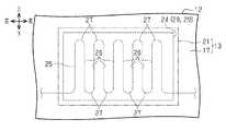
フロントグリル12の骨格部分は、グリル本体13によって構成されている。グリル本体13の一部、ここでは車幅方向における中央部上部には、図1において二点鎖線で示すエンブレム14を取り付けるための取り付け孔15が形成されている。取り付け孔15は、ミリ波レーダ装置40に対しては、斜め前上方に位置している。グリル本体13の下部には、格子状をなすロアグリル16が形成されている。ロアグリル16は、ミリ波レーダ装置40に対しては、斜め前下方に位置している。 The skeleton portion of the
グリル本体13の一部であって、ミリ波レーダ装置40の前方となる箇所は、ミリ波透過性を有するミリ波透過部21によって構成されている。ミリ波透過部21は、上記取り付け孔15とロアグリル16との間に位置している。 A part of the grill
なお、グリル本体13において、ミリ波透過部21と、それ以外の箇所とを区別するために、後者をグリル一般部17というものとする。グリル本体13では、ミリ波透過部21とグリル一般部17とが、境界部分に凹凸がない状態で一体に形成されている。上述した取り付け孔15やロアグリル16は、このグリル一般部17に形成されている。グリル一般部17の周縁部の複数箇所には取り付け座18が形成されている。フロントグリル12は、これらの取り付け座18において、車体に対し直接に又は他の部品を介して間接に取り付けられている。 In the grill
グリル本体13におけるミリ波透過部21及びグリル一般部17は、透明な樹脂材料により形成された基材22と、基材22の後面に形成された加飾層23とを備えている。本実施形態では、透明な樹脂材料として、PC(ポリカーボネート)樹脂が用いられているが、それ以外にもPMMA(ポリメタクリル酸メチル)樹脂が用いられてもよい。 The millimeter
加飾層23は、ミリ波透過部21を含めグリル本体13を装飾するためのものである。加飾層23は、例えば、塗装、印刷等をすることで、黒色、青色、赤色等の色が着いた状態で形成される有色層によって構成されている。 The
上記加飾層23は金属光沢を有する光輝加飾層によって構成されてもよい。光輝加飾層は、例えば、金属皮膜によって構成される。この場合、金属皮膜が一面にわたって連続した状態で形成されると、ミリ波が遮断又は大きく減衰される。そのため、金属皮膜は、インジウム等の金属材料によって海島構造をなすように形成される。海島構造は、金属皮膜が一面に連続しておらず、多数の微細な金属皮膜が島状に互いに僅かに離間し又は一部接触した状態で敷き詰められてなる不連続構造である。この構造を採用することにより、金属皮膜は不連続構造となり、電気抵抗が高くなり、ミリ波透過性を有する。金属被膜は、例えば、スパッタリング、蒸着等により形成される。 The
また、金属被膜が海島構造をなすように形成される場合には、金属被膜の耐食性向上等のために、同金属皮膜の後側に黒色等の有色の押さえ塗膜が形成されてもよい。
さらに、加飾層23は、有色層及び光輝加飾層の組み合わせによって構成されてもよい。When the metal film is formed to have a sea-island structure, a colored pressing film such as black may be formed on the rear side of the metal film in order to improve the corrosion resistance of the metal film.
Further, the
ところで、ミリ波透過部21には、ミリ波が透過する際に生ずる減衰量が少ないことが要求される。一方で、ミリ波の減衰量と、ミリ波透過部21の厚みとの間に一定の関係があること、すなわち、一定の条件(下記式1参照)を満たす複数の厚みでは減衰量が少なくなることが判っている。 By the way, the millimeter
このことから、本実施形態では、前後方向におけるミリ波透過部21の寸法(厚み)をTとし、ミリ波の波長をλeとし、基材22の比誘電率をεpとし、整数をnとしたとき、厚みTが、次式1を満たす値に設定されている。 Accordingly, in the present embodiment, the dimension (thickness) of the millimeter
T={(λe/2)/√(εp)}n・・・(式1)
このように、ミリ波透過部21の厚みTは、半波長を比誘電率の平方根にて除算した値の整数倍の値に設定されている。整数nは2,3が好ましく、基材22が上記のようにPC樹脂によって形成される場合には、厚みTは、2.4mm、3.6mmに設定される。この厚みであると、フロントグリル12としての剛性を保持し、かつ発熱体24を配置しても熱伝導性もよく、融雪の機能も満足する。T = {(λe / 2) / √ (εp)} n (Equation 1)
As described above, the thickness T of the millimeter
なお、グリル本体13のうち、グリル一般部17については、ミリ波の透過性が要求されない。そのため、グリル一般部17については、上記のような厚みについての制約を受けない。グリル一般部17の厚みは、上記式1を満たさない値に設定されてもよい。また、グリル一般部17については、厚みが均一に設定されてもされなくてもよく、前後方向に凹凸状をなす形状に形成されてもよい。 The grill
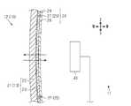
ミリ波透過部21の後面には発熱体24が固定されている。発熱体24は、通電により発熱するヒータ線25と、樹脂材料により形成され、かつヒータ線25を前後両側から挟み込むことでヒータ線25を被覆する一対のシート28,29とを備えている。こうした構成の発熱体24は、面状発熱体、フィルムヒータ等とも呼ばれる。 A
ヒータ線25としては、例えば、ニクロム線が用いられる。そのほかにも、ヒータ線25として、透明導電膜、カーボン発熱体、銀ペースト等によって線状に形成されたものが用いられてもよい。このうち、透明導電膜は、例えば、ITO(酸化インジウムスズ)を材料として用い、スパッタリング、蒸着等することによって形成される。この場合には、ヒータ線25が見えにくくなるため、発熱体24の見栄えが向上する。これに伴い、ミリ波透過部21、ひいてはグリル本体13の外観品質が向上する。 As the
図2に示すように、ヒータ線25は、波形状に繰り返し屈曲された状態で形成されている。より詳しくは、ヒータ線25は、互いに平行な状態で延びる複数の直線部26と、隣り合う直線部26の端部同士を連結する折り返し部27とを備えている。 As shown in FIG. 2, the
図3に示すように、シート28,29は、PC樹脂等の透明な樹脂材料によって形成されており、ミリ波透過性を有している。なお、シート28,29として、可撓性を有する積層体であり、フィルムと呼ばれる薄い積層体が用いられてもよい。 As shown in FIG. 3, the
そして、発熱体24は、前側のシート28の前面において、ミリ波透過部21(加飾層23)の後面に対し、接着により固定されている。
発熱体24は、フロントグリル12の製造に際し、グリル本体13の成形後に、次の発熱体固定工程が行われることにより、ミリ波透過部21に固定される。すなわち、発熱体固定工程では、発熱体24における前側のシート28が、真空状態のもとで、ミリ波透過部21の後面に接着される。そのため、ミリ波透過部21との間に気泡が入るのを抑制しつつ、発熱体24を同ミリ波透過部21に固定することが可能である。The
The
次に、上記のように構成された本実施形態のフロントグリル12の作用及び効果について説明する。
フロントグリル12では、加飾層23を有するミリ波透過部21が、そのミリ波透過部21よりも後側に配置されている発熱体24及びミリ波レーダ装置40を覆い隠す機能を発揮する。そのため、車両10の前方から発熱体24及びミリ波レーダ装置40が見えるのを抑制することができる。Next, the operation and effect of the
In the
また、フロントグリル12を車両10の前方から見た場合、ミリ波透過部21では、透明な基材22を通して、同基材22の後面に形成された加飾層23が見える。表現を変えると、透明な基材22の前面から後方へ奥まった箇所に加飾層23が位置するように見える。加飾層23は、ミリ波透過部21を装飾する機能を発揮する。従って、加飾層23によってミリ波透過部21ひいてはグリル本体13の外観品質を向上することができる。 Further, when the
ミリ波レーダ装置40から前方へミリ波が送信されると、そのミリ波は、図3において矢印で示すように、同ミリ波レーダ装置40の前方に位置する発熱体24のうち、ヒータ線25の設けられていない箇所を透過する。また、ミリ波は、発熱体24の前側に位置するミリ波透過部21を透過する。この際、加飾層23が金属被膜によって構成されている場合には、ミリ波は、蒸着等された金属粒子間の隙間を透過する。先行車両、歩行者等を含む車外の対象物に当たって反射されたミリ波は、上記送信されたミリ波と同様にミリ波透過部21及び発熱体24を透過し、ミリ波レーダ装置40によって受信される。ミリ波レーダ装置40では、送信及び受信されたミリ波により、車両10と対象物との距離や相対速度が検出される。 When the millimeter wave is transmitted forward from the millimeter
ここで、本実施形態では、ミリ波透過部21の厚みTが、同ミリ波透過部21の部位によらず上記の式1を満たす値に均一に設定されている。そのため、ミリ波がミリ波透過部21を透過する際に生ずる減衰量が、上記式1を満たさない場合よりも少なくされる。式1を満たさないものには、ミリ波透過部21が前後方向に凹凸状をなすように形成されていて、前後方向の厚みが均一でないものも含まれる。 Here, in the present embodiment, the thickness T of the millimeter-
また、ヒータ線25が通電により発熱すると、その熱はミリ波透過部21に伝わる。従って、ミリ波透過部21の前面に雪が付着しても、その雪は、ヒータ線25から伝わる熱によって溶かされ、雪によるミリ波の減衰が抑制される。雪の付着が原因でミリ波レーダ装置40の検出性能が低下するのを抑制することができる。 Further, when the
本実施形態によると、上記以外にも、次の効果が得られる。
・発熱体24として、樹脂材料により形成された一対のシート28,29によって、ヒータ線25を前後両側から挟み込んで被覆する構成を有するものを用いている。そのため、発熱体24における前側のシート28をミリ波透過部21の後面に固定することで、ヒータ線25を、所定の配線パターンで、ミリ波透過部21の後側に配置することができる。According to the present embodiment, the following effects can be obtained in addition to the above.
The
・ミリ波透過部21を、上記エンブレム14と同様に、グリル一般部17とは別の部品によって構成することも可能である。この場合、グリル一般部17に孔が形成され、ここにミリ波透過部21が嵌め込まれることにより、両者が結合される。しかし、別体のミリ波透過部21とグリル一般部17との境界部分に分割線が生じ、グリル本体13の外観品質が低下する。 The millimeter
この点、本実施形態では、ミリ波透過部21がグリル本体13の一部として、グリル一般部17に一体に形成されている。そのため、ミリ波透過部21とグリル一般部17との境界部分に分割線が生じず、グリル本体13の外観品質の向上を図ることができる。 In this regard, in the present embodiment, the millimeter
・上述したように、グリル本体13では、ミリ波の透過がミリ波透過部21において行われる。そのため、グリル本体13において、ミリ波透過部21とは異なる箇所であるグリル一般部17には、ミリ波の透過性が要求されない。該当する箇所には、取り付け孔15が含まれる。取り付け孔15においてグリル一般部17に取り付けられるエンブレム14についても、ミリ波の透過性が要求されない。従って、エンブレム14及び取り付け孔15に対し、ミリ波を透過させる役割とは異なる役割、例えば、発光部、電気車両における充電ポート等の設置箇所となるといった役割を担わせることで、フロントグリル12の多機能化を図ることが可能となる。 As described above, in the grill
なお、上記実施形態は、これを以下のように変更した変形例として実施することもできる。
・ヒータ線25は、ミリ波の透過を阻害しにくい配線パターンで配置されることが望ましい。この観点からは、ヒータ線25の少なくとも一部は、ミリ波透過部21におけるミリ波の透過領域よりも外側に配置されてもよい。透過領域に配置された場合に比べ、ミリ波の透過が妨げられにくく、ミリ波が発熱体24を透過する際の減衰量が少なくなるからである。The above embodiment can be implemented as a modified example in which this is changed as follows.
It is desirable that the
例えば、上記実施形態では、各折り返し部27がミリ波の透過領域から外れた箇所に配置されてもよい。
また、ヒータ線25が、上記透過領域を取り囲む環状となるように配置されてもよい。このようにすると、ヒータ線25がミリ波の透過を妨げるのを抑制する効果が得られるほかにも、次の効果もある。通電によりヒータ線25が発熱すると、その熱の一部は、ミリ波透過部21のうちヒータ線25によって囲まれた領域(透過領域)の中心部に向けて、全方向から伝わる。フロントグリル12の前面であってミリ波透過部21に対応する箇所に雪が付着しても、その雪を、付着箇所に拘わらずヒータ線25からの熱によって一様に溶かすことが可能である。For example, in the above embodiment, each folded
Further, the
また、ヒータ線25は、一直線状をなすように配置されてもよい。この形状のヒータ線25が用いられる場合にも、ミリ波の透過を妨げにくくするために、同ヒータ線25は、上記と同様、ミリ波透過部21のうちミリ波の透過領域よりも外側の部分に配置されることが望ましい。 Further, the
・発熱体24におけるシート28,29の一方が省略されてもよい。
・発熱体24からシート28,29が省略され、シート28,29が用いられることなくヒータ線25が単独でミリ波透過部21に配置されてもよい。-One of the
The
・フロントグリル12の製造に際し、発熱体固定工程における発熱体24のミリ波透過部21に対する固定が、真空圧空成形法によって行われてもよい。真空圧空成形法は、ヒータ線25を一対のシート28,29で挟み込んでなる発熱体24を室温で又は加熱雰囲気下で、延伸させながら、圧力差を用いて、予め成形されたグリル本体13におけるミリ波透過部21の後面に貼り付ける方法である。 When manufacturing the
グリル本体13の成形後に、発熱体24を上記真空圧空成形によりミリ波透過部21の後面に貼り付けることで、同発熱体24をミリ波透過部21に固定することができる。
・上記実施形態におけるグリル一般部17の一部又は全部については、基材22及び加飾層23を備えるといったミリ波透過部21の構成とは異なる構成が採られてもよい。After the grill
-About a part or all of the grill
・グリル本体13における加飾層23が基材22の後面に代えて、前面に形成されてもよい。この場合には、基材22は必ずしも透明な樹脂材料によって形成されなくてもよい。 The
・グリル本体13における基材22は、それ自体が加飾機能を有するものであってもよい。この場合には、加飾層23は不要である。
・上記実施形態では、発熱体24がミリ波透過部21の後側に位置する。そのため、シート28,29は、必ずしも透明な樹脂材料によって形成されなくてもよい。-The
In the above embodiment, the
・図4に示すように、発熱体24がミリ波透過部21の前側に配置され、後側のシート29においてミリ波透過部21(基材22)の前面に固定されてもよい。シート28,29としては、上記実施形態と同様、PC等の透明な樹脂材料によって形成されたものが用いられることが望ましい。なお、図4において、上記実施形態で説明したものと同様の要素には同一の符号が付されている。 As shown in FIG. 4, the
この場合には、発熱体24に雪が付着しても、ヒータ線25が通電されることで発熱すれば、その熱により雪が溶かされ、雪によるミリ波の減衰が抑制される。ヒータ線25が雪に近い箇所で発熱するため、発熱体24がミリ波透過部21の後側に配置される上記実施形態に比べ、ヒータ線25の熱が雪に伝わりやすく、雪を効率よく溶かすことができる。 In this case, even if snow adheres to the
また、フロントグリル12を車両10の前方から見た場合、シート28,29が透明な樹脂材料によって形成された発熱体24、透明な基材22を通して加飾層23が見える。発熱体24が加飾層23の装飾機能を損なうのを抑制することができる。 Further, when the
・フロントグリル12は、上記実施形態とは異なり、グリル一般部17に取り付け孔15が設けられず、別体のエンブレム14が取り付けられないものであってもよい。
その他、上記各実施形態から把握できる技術的思想について、それらの効果とともに記載する。The
In addition, technical ideas that can be grasped from the above embodiments will be described together with their effects.
(A)ミリ波を前方へ送信するとともに反射されたミリ波を受信するミリ波レーダ装置が搭載された車両において、同ミリ波レーダ装置よりも前側に配置されるグリル本体を骨格部分として備え、
前記グリル本体の一部であって前記ミリ波レーダ装置の前方となる箇所が、ミリ波透過性を有するミリ波透過部により構成され、
ミリ波透過性を有する発熱体が前記ミリ波透過部の前面及び後面の一方に設けられ、
前記発熱体が、通電により発熱するヒータ線と、樹脂材料により形成され、かつ前記ヒータ線を前後両側から挟み込む一対のシートとを備え、一方の前記シートにおいて前記ミリ波透過部に固定される車両用フロントグリルを製造する方法であって、
前記グリル本体の成形後に、前記発熱体における一方のシートを真空状態のもとで、前記ミリ波透過部の前面及び後面の一方に接着することにより、同発熱体を前記ミリ波透過部に固定する発熱体固定工程を備える車両用フロントグリルの製造方法。(A) In a vehicle equipped with a millimeter wave radar device that transmits a millimeter wave forward and receives a reflected millimeter wave, a grill main body disposed on a front side of the millimeter wave radar device is provided as a skeleton portion,
A part of the grill main body, which is located in front of the millimeter wave radar device, is configured by a millimeter wave transmitting unit having millimeter wave transparency,
A heating element having a millimeter wave transmission property is provided on one of the front surface and the rear surface of the millimeter wave transmission portion,
A vehicle in which the heating element includes a heater wire that generates heat when energized, and a pair of sheets formed of a resin material and sandwiching the heater wire from both front and rear sides, and one of the sheets is fixed to the millimeter wave transmitting portion. Manufacturing a front grill for
After the grill main body is formed, one sheet of the heating element is adhered to one of a front surface and a rear surface of the millimeter wave transmitting section under a vacuum state, thereby fixing the heating element to the millimeter wave transmitting section. Of manufacturing a vehicle front grill including a heating element fixing step.
上記の製造方法によれば、フロントグリルの製造に際し、グリル本体が成形された後に行われる発熱体固定工程では、発熱体における一方のシートが真空状態のもとで、ミリ波透過部の前面及び後面の一方に接着される。そのため、ミリ波透過部との間に気泡が入るのを抑制しつつ発熱体を同ミリ波透過部に固定することが可能である。 According to the above manufacturing method, in the manufacturing of the front grill, in the heating element fixing step performed after the grill main body is formed, one sheet of the heating element is under a vacuum state, and the front surface of the millimeter wave transmitting portion and Glued to one of the rear surfaces. Therefore, it is possible to fix the heating element to the millimeter-wave transmitting portion while suppressing air bubbles from entering the millimeter-wave transmitting portion.
(B)ミリ波を前方へ送信するとともに反射されたミリ波を受信するミリ波レーダ装置が搭載された車両において、同ミリ波レーダ装置よりも前側に配置されるグリル本体を骨格部分として備え、
前記グリル本体の一部であって前記ミリ波レーダ装置の前方となる箇所が、ミリ波透過性を有するミリ波透過部により構成され、
ミリ波透過性を有する発熱体が前記ミリ波透過部の前面及び後面の一方に設けられ、
前記発熱体が、通電により発熱するヒータ線と、樹脂材料により形成され、かつ前記ヒータ線を前後両側から挟み込む一対のシートとを備え、一方の前記シートにおいて前記ミリ波透過部に固定される車両用フロントグリルを製造する方法であって、
前記グリル本体の成形後に、前記発熱体を真空圧空成形法により前記ミリ波透過部の前面及び後面の一方に貼り付けることで、同発熱体をミリ波透過部に固定する発熱体固定工程を備える車両用フロントグリルの製造方法。(B) In a vehicle equipped with a millimeter wave radar device that transmits a millimeter wave forward and receives a reflected millimeter wave, a grill main body disposed on the front side of the millimeter wave radar device is provided as a skeleton portion,
A part of the grill main body, which is located in front of the millimeter wave radar device, is configured by a millimeter wave transmitting unit having millimeter wave transparency,
A heating element having a millimeter wave transmission property is provided on one of the front surface and the rear surface of the millimeter wave transmission portion,
A vehicle in which the heating element includes a heater wire that generates heat when energized, and a pair of sheets formed of a resin material and sandwiching the heater wire from both front and rear sides, and one of the sheets is fixed to the millimeter wave transmitting portion. Manufacturing a front grill for
After the grill main body is formed, a heating element fixing step of fixing the heating element to the millimeter wave transmitting section by attaching the heating element to one of the front surface and the rear surface of the millimeter wave transmitting section by a vacuum pressure forming method is provided. Manufacturing method of vehicle front grille.
上記の製造方法によれば、フロントグリルの製造に際し、グリル本体が成形された後に行われる発熱体固定工程では、発熱体が真空圧空成形法によりミリ波透過部の前面及び後面の一方に貼り付けられる。この貼り付けにより、発熱体がミリ波透過部に固定される。 According to the above manufacturing method, in the manufacturing of the front grill, in the heating element fixing step performed after the grill main body is formed, the heating element is attached to one of the front surface and the rear surface of the millimeter wave transmitting portion by a vacuum pressure forming method. Can be By this attachment, the heating element is fixed to the millimeter wave transmitting portion.
10…車両、12…フロントグリル、13…グリル本体、14…エンブレム、15…取り付け孔、21…ミリ波透過部、22…基材、23…加飾層、24…発熱体、25…ヒータ線、28,29…シート、40…ミリ波レーダ装置。 DESCRIPTION OF
Claims (5)
Translated fromJapanese前記グリル本体の一部であって前記ミリ波レーダ装置の前方となる箇所は、ミリ波透過性を有するミリ波透過部により構成され、
前記ミリ波透過部の前面及び後面の一方には、通電により発熱するヒータ線を有するとともにミリ波透過性を有する発熱体が固定されている車両用フロントグリル。In a vehicle equipped with a millimeter wave radar device that transmits a millimeter wave to the front and receives a reflected millimeter wave, a grill main body disposed on the front side of the millimeter wave radar device as a skeleton portion,
A part of the grill main body, which is located in front of the millimeter wave radar device, is configured by a millimeter wave transmitting portion having millimeter wave transparency,
A vehicular front grille having a heater wire that generates heat when energized and a heating element that has millimeter wave transparency fixed to one of a front surface and a rear surface of the millimeter wave transmitting portion.
前記ミリ波透過部の全体について、前記厚みTが次式
T={(λe/2)/√(εp)}n
を満たす値に設定されている請求項2に記載の車両用フロントグリル。When the thickness of the millimeter wave transmitting portion in the front-rear direction is T, the wavelength of the millimeter wave is λe, the relative permittivity of the substrate is εp, and the integer is n,
For the entirety of the millimeter wave transmitting portion, the thickness T is expressed by the following equation:
The vehicle front grill according to claim 2, wherein the value is set to a value that satisfies the following.
前記発熱体は、一方の前記シートにおいて前記ミリ波透過部の前面及び後面の一方に固定されている請求項1〜3のいずれか1項に記載の車両用フロントグリル。The heating element further includes a pair of sheets formed of a resin material and sandwiching the heater wire from both front and rear sides,
The vehicle front grill according to any one of claims 1 to 3, wherein the heating element is fixed to one of a front surface and a rear surface of the millimeter wave transmitting portion on one of the sheets.
前記ミリ波透過部は前記取り付け孔から離間した箇所に形成されている請求項1〜4のいずれか1項に記載の車両用フロントグリル。An attachment hole for attaching an emblem is formed in the grill body,
The vehicle front grill according to any one of claims 1 to 4, wherein the millimeter wave transmitting portion is formed at a location separated from the mounting hole.
Priority Applications (2)
| Application Number | Priority Date | Filing Date | Title |
|---|---|---|---|
| JP2018172409AJP7081414B2 (en) | 2018-09-14 | 2018-09-14 | Vehicle front grill |
| JP2022023916AJP2022085907A (en) | 2018-09-14 | 2022-02-18 | Front grille for vehicle |
Applications Claiming Priority (1)
| Application Number | Priority Date | Filing Date | Title |
|---|---|---|---|
| JP2018172409AJP7081414B2 (en) | 2018-09-14 | 2018-09-14 | Vehicle front grill |
Related Child Applications (1)
| Application Number | Title | Priority Date | Filing Date |
|---|---|---|---|
| JP2022023916ADivisionJP2022085907A (en) | 2018-09-14 | 2022-02-18 | Front grille for vehicle |
Publications (2)
| Publication Number | Publication Date |
|---|---|
| JP2020044869Atrue JP2020044869A (en) | 2020-03-26 |
| JP7081414B2 JP7081414B2 (en) | 2022-06-07 |
Family
ID=69900495
Family Applications (2)
| Application Number | Title | Priority Date | Filing Date |
|---|---|---|---|
| JP2018172409AActiveJP7081414B2 (en) | 2018-09-14 | 2018-09-14 | Vehicle front grill |
| JP2022023916APendingJP2022085907A (en) | 2018-09-14 | 2022-02-18 | Front grille for vehicle |
Family Applications After (1)
| Application Number | Title | Priority Date | Filing Date |
|---|---|---|---|
| JP2022023916APendingJP2022085907A (en) | 2018-09-14 | 2022-02-18 | Front grille for vehicle |
Country Status (1)
| Country | Link |
|---|---|
| JP (2) | JP7081414B2 (en) |
Cited By (12)
| Publication number | Priority date | Publication date | Assignee | Title |
|---|---|---|---|---|
| WO2021049114A1 (en)* | 2019-09-09 | 2021-03-18 | 三恵技研工業株式会社 | Method for manufacturing radome for vehicle-mounted radar device |
| CN113183906A (en)* | 2021-05-24 | 2021-07-30 | 上海电器科学研究所(集团)有限公司 | Automatic supply vehicle air inlet protective fence that snow frost condenses is prevented to constant temperature |
| CN113267782A (en)* | 2021-05-18 | 2021-08-17 | 沈阳工程学院 | Self-generating heating type acoustic radar protection device and control method thereof |
| JP2021166145A (en)* | 2020-04-07 | 2021-10-14 | 株式会社デンソー | Film heater |
| JP7100327B1 (en) | 2021-04-19 | 2022-07-13 | 南部化成株式会社 | Emblem for vehicles with built-in heater and its manufacturing method |
| WO2022185764A1 (en)* | 2021-03-02 | 2022-09-09 | 三恵技研工業株式会社 | Radome for vehicle-mounted radar device and manufacturing method therefor |
| JP2022134100A (en)* | 2021-03-02 | 2022-09-14 | 三恵技研工業株式会社 | Radome for in-vehicle radar device and manufacturing method thereof |
| JP2022143267A (en)* | 2021-03-17 | 2022-10-03 | サカエ理研工業株式会社 | Vehicle exterior parts |
| JP2022156509A (en)* | 2021-03-31 | 2022-10-14 | 豊田合成株式会社 | Vehicle component to be heated |
| EP4155132A1 (en) | 2021-09-28 | 2023-03-29 | Toyoda Gosei Co., Ltd. | Vehicle component |
| JP2023069443A (en)* | 2021-11-05 | 2023-05-18 | 豊田合成株式会社 | VEHICLE EXTERIOR COVER AND METHOD FOR MANUFACTURING VEHICLE EXTERIOR COVER |
| JP2024048851A (en)* | 2022-09-28 | 2024-04-09 | 豊田合成株式会社 | Vehicle exterior structure and vehicle ice melting system |
Families Citing this family (1)
| Publication number | Priority date | Publication date | Assignee | Title |
|---|---|---|---|---|
| JP7411050B1 (en) | 2022-11-04 | 2024-01-10 | 三恵技研工業株式会社 | radome |
Citations (8)
| Publication number | Priority date | Publication date | Assignee | Title |
|---|---|---|---|---|
| JP2005112193A (en)* | 2003-10-08 | 2005-04-28 | Toyota Motor Corp | Radiator grille structure |
| JP2015110836A (en)* | 2014-11-10 | 2015-06-18 | 三恵技研工業株式会社 | Metal coating for electromagnetic wave transmission and radome for in-vehicle radar equipment |
| DE102014002438A1 (en)* | 2014-02-20 | 2015-08-20 | Daimler Ag | Manufacturing method for a plastic radome of a motor vehicle |
| DE102014214329A1 (en)* | 2014-07-23 | 2016-01-28 | Conti Temic Microelectronic Gmbh | radar device |
| JP2017215242A (en)* | 2016-06-01 | 2017-12-07 | 豊田合成株式会社 | Vehicle decorative part |
| JP2018505383A (en)* | 2014-11-03 | 2018-02-22 | イリノイ トゥール ワークス インコーポレイティド | Permeable front heater for vehicle sensor system |
| JP2018066706A (en)* | 2016-10-21 | 2018-04-26 | 豊田合成株式会社 | Decorative component for vehicle and method for manufacturing the same |
| JP2018111367A (en)* | 2017-01-10 | 2018-07-19 | トヨタ自動車株式会社 | Vehicular periphery detection sensor mounting mechanism |
Family Cites Families (2)
| Publication number | Priority date | Publication date | Assignee | Title |
|---|---|---|---|---|
| JP2014069634A (en)* | 2012-09-28 | 2014-04-21 | Toyoda Gosei Co Ltd | Vehicle decorative member |
| JP6450671B2 (en)* | 2015-11-16 | 2019-01-09 | 豊田合成株式会社 | Decorative body and manufacturing method thereof |
- 2018
- 2018-09-14JPJP2018172409Apatent/JP7081414B2/enactiveActive
- 2022
- 2022-02-18JPJP2022023916Apatent/JP2022085907A/enactivePending
Patent Citations (8)
| Publication number | Priority date | Publication date | Assignee | Title |
|---|---|---|---|---|
| JP2005112193A (en)* | 2003-10-08 | 2005-04-28 | Toyota Motor Corp | Radiator grille structure |
| DE102014002438A1 (en)* | 2014-02-20 | 2015-08-20 | Daimler Ag | Manufacturing method for a plastic radome of a motor vehicle |
| DE102014214329A1 (en)* | 2014-07-23 | 2016-01-28 | Conti Temic Microelectronic Gmbh | radar device |
| JP2018505383A (en)* | 2014-11-03 | 2018-02-22 | イリノイ トゥール ワークス インコーポレイティド | Permeable front heater for vehicle sensor system |
| JP2015110836A (en)* | 2014-11-10 | 2015-06-18 | 三恵技研工業株式会社 | Metal coating for electromagnetic wave transmission and radome for in-vehicle radar equipment |
| JP2017215242A (en)* | 2016-06-01 | 2017-12-07 | 豊田合成株式会社 | Vehicle decorative part |
| JP2018066706A (en)* | 2016-10-21 | 2018-04-26 | 豊田合成株式会社 | Decorative component for vehicle and method for manufacturing the same |
| JP2018111367A (en)* | 2017-01-10 | 2018-07-19 | トヨタ自動車株式会社 | Vehicular periphery detection sensor mounting mechanism |
Cited By (20)
| Publication number | Priority date | Publication date | Assignee | Title |
|---|---|---|---|---|
| JP2021043019A (en)* | 2019-09-09 | 2021-03-18 | 三恵技研工業株式会社 | Method of manufacturing radome for on-vehicle radar system |
| WO2021049114A1 (en)* | 2019-09-09 | 2021-03-18 | 三恵技研工業株式会社 | Method for manufacturing radome for vehicle-mounted radar device |
| JP7528506B2 (en) | 2020-04-07 | 2024-08-06 | 株式会社デンソー | Film Heater |
| JP2021166145A (en)* | 2020-04-07 | 2021-10-14 | 株式会社デンソー | Film heater |
| WO2021206022A1 (en)* | 2020-04-07 | 2021-10-14 | 株式会社デンソー | Film heater |
| JP7736418B2 (en) | 2021-03-02 | 2025-09-09 | 三恵技研工業株式会社 | Radome for vehicle-mounted radar device and manufacturing method thereof |
| WO2022185764A1 (en)* | 2021-03-02 | 2022-09-09 | 三恵技研工業株式会社 | Radome for vehicle-mounted radar device and manufacturing method therefor |
| JP2022134100A (en)* | 2021-03-02 | 2022-09-14 | 三恵技研工業株式会社 | Radome for in-vehicle radar device and manufacturing method thereof |
| JP2022143267A (en)* | 2021-03-17 | 2022-10-03 | サカエ理研工業株式会社 | Vehicle exterior parts |
| JP2022156509A (en)* | 2021-03-31 | 2022-10-14 | 豊田合成株式会社 | Vehicle component to be heated |
| JP7501431B2 (en) | 2021-03-31 | 2024-06-18 | 豊田合成株式会社 | Heated vehicle part and manufacturing method thereof |
| JP7100327B1 (en) | 2021-04-19 | 2022-07-13 | 南部化成株式会社 | Emblem for vehicles with built-in heater and its manufacturing method |
| WO2022224774A1 (en)* | 2021-04-19 | 2022-10-27 | 南部化成株式会社 | Emblem for vehicle with built-in heater, and manufacturing method thereof |
| JP2022165303A (en)* | 2021-04-19 | 2022-10-31 | 南部化成株式会社 | Emblem for vehicle with built-in heater and manufacturing method thereof |
| CN113267782B (en)* | 2021-05-18 | 2023-10-03 | 沈阳工程学院 | Sodar protection device capable of self-heating and control method thereof |
| CN113267782A (en)* | 2021-05-18 | 2021-08-17 | 沈阳工程学院 | Self-generating heating type acoustic radar protection device and control method thereof |
| CN113183906A (en)* | 2021-05-24 | 2021-07-30 | 上海电器科学研究所(集团)有限公司 | Automatic supply vehicle air inlet protective fence that snow frost condenses is prevented to constant temperature |
| EP4155132A1 (en) | 2021-09-28 | 2023-03-29 | Toyoda Gosei Co., Ltd. | Vehicle component |
| JP2023069443A (en)* | 2021-11-05 | 2023-05-18 | 豊田合成株式会社 | VEHICLE EXTERIOR COVER AND METHOD FOR MANUFACTURING VEHICLE EXTERIOR COVER |
| JP2024048851A (en)* | 2022-09-28 | 2024-04-09 | 豊田合成株式会社 | Vehicle exterior structure and vehicle ice melting system |
Also Published As
| Publication number | Publication date |
|---|---|
| JP7081414B2 (en) | 2022-06-07 |
| JP2022085907A (en) | 2022-06-08 |
Similar Documents
| Publication | Publication Date | Title |
|---|---|---|
| JP7081414B2 (en) | Vehicle front grill | |
| JP7042999B2 (en) | Radio wave transmission cover | |
| US11634089B2 (en) | Decorative part for vehicle and method for manufacturing same | |
| JP6665691B2 (en) | Decorative parts for vehicles | |
| JP6658313B2 (en) | Decorative parts for vehicles | |
| JP6652031B2 (en) | Vehicle decorative component and method of manufacturing the same | |
| JP7312608B2 (en) | Decorative parts for vehicles | |
| JP6901566B2 (en) | Radome for vehicles | |
| US10651530B2 (en) | Decorative component for vehicle | |
| JP2018066705A (en) | Vehicle decorative part | |
| JP2014069634A (en) | Vehicle decorative member | |
| WO2019065165A1 (en) | Decorative component for vehicle | |
| JP2019166888A (en) | Vehicular decorative component | |
| US11594813B2 (en) | Method for producing a layered structure in a multi-component process | |
| JP7031434B2 (en) | Manufacturing method of decorative parts for vehicles and decorative parts for vehicles | |
| JP7131506B2 (en) | In-vehicle sensor cover | |
| JP2021178440A (en) | Decorative panel structure and production method thereof | |
| JP2021194992A (en) | Vehicular external component | |
| JP2023048416A (en) | Vehicle component | |
| JP7115380B2 (en) | Decorative parts for vehicles |
Legal Events
| Date | Code | Title | Description |
|---|---|---|---|
| A621 | Written request for application examination | Free format text:JAPANESE INTERMEDIATE CODE: A621 Effective date:20201028 | |
| A977 | Report on retrieval | Free format text:JAPANESE INTERMEDIATE CODE: A971007 Effective date:20210806 | |
| A131 | Notification of reasons for refusal | Free format text:JAPANESE INTERMEDIATE CODE: A131 Effective date:20210817 | |
| A521 | Request for written amendment filed | Free format text:JAPANESE INTERMEDIATE CODE: A523 Effective date:20211018 | |
| A02 | Decision of refusal | Free format text:JAPANESE INTERMEDIATE CODE: A02 Effective date:20211124 | |
| A521 | Request for written amendment filed | Free format text:JAPANESE INTERMEDIATE CODE: A523 Effective date:20220218 | |
| C60 | Trial request (containing other claim documents, opposition documents) | Free format text:JAPANESE INTERMEDIATE CODE: C60 Effective date:20220218 | |
| A911 | Transfer to examiner for re-examination before appeal (zenchi) | Free format text:JAPANESE INTERMEDIATE CODE: A911 Effective date:20220301 | |
| C21 | Notice of transfer of a case for reconsideration by examiners before appeal proceedings | Free format text:JAPANESE INTERMEDIATE CODE: C21 Effective date:20220308 | |
| TRDD | Decision of grant or rejection written | ||
| A01 | Written decision to grant a patent or to grant a registration (utility model) | Free format text:JAPANESE INTERMEDIATE CODE: A01 Effective date:20220426 | |
| A61 | First payment of annual fees (during grant procedure) | Free format text:JAPANESE INTERMEDIATE CODE: A61 Effective date:20220509 | |
| R150 | Certificate of patent or registration of utility model | Ref document number:7081414 Country of ref document:JP Free format text:JAPANESE INTERMEDIATE CODE: R150 |