JP2020032252A - Apparatus for measurement of tissue thickness using ultrasound and force measurement - Google Patents
Apparatus for measurement of tissue thickness using ultrasound and force measurementDownload PDFInfo
- Publication number
- JP2020032252A JP2020032252AJP2019209439AJP2019209439AJP2020032252AJP 2020032252 AJP2020032252 AJP 2020032252AJP 2019209439 AJP2019209439 AJP 2019209439AJP 2019209439 AJP2019209439 AJP 2019209439AJP 2020032252 AJP2020032252 AJP 2020032252A
- Authority
- JP
- Japan
- Prior art keywords
- catheter
- cavity
- wall
- operable
- tissue
- Prior art date
- Legal status (The legal status is an assumption and is not a legal conclusion. Google has not performed a legal analysis and makes no representation as to the accuracy of the status listed.)
- Granted
Links
- 238000002604ultrasonographyMethods0.000titleclaimsdescription23
- 238000005259measurementMethods0.000titledescription11
- 230000002596correlated effectEffects0.000claimsabstractdescription8
- 230000033001locomotionEffects0.000claimsdescription26
- 238000003780insertionMethods0.000claimsdescription4
- 230000037431insertionEffects0.000claimsdescription4
- 230000004044responseEffects0.000claimsdescription3
- 230000001360synchronised effectEffects0.000claimsdescription3
- 238000010586diagramMethods0.000abstractdescription3
- 210000001519tissueAnatomy0.000description60
- 238000000034methodMethods0.000description47
- 238000002679ablationMethods0.000description21
- 206010003119arrhythmiaDiseases0.000description6
- 230000003902lesionEffects0.000description5
- 239000000523sampleSubstances0.000description5
- 230000006793arrhythmiaEffects0.000description4
- 125000004122cyclic groupChemical group0.000description4
- 210000005003heart tissueAnatomy0.000description4
- 238000012545processingMethods0.000description4
- 230000002159abnormal effectEffects0.000description3
- 230000000694effectsEffects0.000description3
- 239000012530fluidSubstances0.000description3
- 230000006870functionEffects0.000description3
- 230000008569processEffects0.000description3
- 230000004913activationEffects0.000description2
- 210000000577adipose tissueAnatomy0.000description2
- 238000004422calculation algorithmMethods0.000description2
- 230000008859changeEffects0.000description2
- 229910003460diamondInorganic materials0.000description2
- 239000010432diamondSubstances0.000description2
- 238000006073displacement reactionMethods0.000description2
- 238000002592echocardiographyMethods0.000description2
- 238000010438heat treatmentMethods0.000description2
- 238000007689inspectionMethods0.000description2
- 210000005240left ventricleAnatomy0.000description2
- 230000037361pathwayEffects0.000description2
- 230000011514reflexEffects0.000description2
- 210000005166vasculatureAnatomy0.000description2
- 206010001497AgitationDiseases0.000description1
- 206010003658Atrial FibrillationDiseases0.000description1
- 206010007559Cardiac failure congestiveDiseases0.000description1
- 206010019280Heart failuresDiseases0.000description1
- 208000007536ThrombosisDiseases0.000description1
- 239000000853adhesiveSubstances0.000description1
- 238000004458analytical methodMethods0.000description1
- 238000013459approachMethods0.000description1
- 230000008901benefitEffects0.000description1
- 238000001574biopsyMethods0.000description1
- 238000004364calculation methodMethods0.000description1
- 230000000747cardiac effectEffects0.000description1
- 230000006835compressionEffects0.000description1
- 238000007906compressionMethods0.000description1
- 238000004590computer programMethods0.000description1
- 230000008602contractionEffects0.000description1
- 230000001276controlling effectEffects0.000description1
- 239000013078crystalSubstances0.000description1
- 230000000881depressing effectEffects0.000description1
- 238000011156evaluationMethods0.000description1
- 239000002360explosiveSubstances0.000description1
- 210000002837heart atriumAnatomy0.000description1
- 238000010191image analysisMethods0.000description1
- 238000003384imaging methodMethods0.000description1
- 238000000691measurement methodMethods0.000description1
- 230000007246mechanismEffects0.000description1
- 238000012986modificationMethods0.000description1
- 230000004048modificationEffects0.000description1
- 210000004165myocardiumAnatomy0.000description1
- 210000000056organAnatomy0.000description1
- 238000013021overheatingMethods0.000description1
- 230000000737periodic effectEffects0.000description1
- 238000010248power generationMethods0.000description1
- 238000003825pressingMethods0.000description1
- 230000033764rhythmic processEffects0.000description1
- 210000005245right atriumAnatomy0.000description1
- 230000035945sensitivityEffects0.000description1
- 238000013519translationMethods0.000description1
- 238000012285ultrasound imagingMethods0.000description1
- 230000002861ventricularEffects0.000description1
- XLYOFNOQVPJJNP-UHFFFAOYSA-NwaterChemical compoundOXLYOFNOQVPJJNP-UHFFFAOYSA-N0.000description1
Images


Classifications
- A—HUMAN NECESSITIES
- A61—MEDICAL OR VETERINARY SCIENCE; HYGIENE
- A61B—DIAGNOSIS; SURGERY; IDENTIFICATION
- A61B8/00—Diagnosis using ultrasonic, sonic or infrasonic waves
- A61B8/42—Details of probe positioning or probe attachment to the patient
- A61B8/4272—Details of probe positioning or probe attachment to the patient involving the acoustic interface between the transducer and the tissue
- A61B8/429—Details of probe positioning or probe attachment to the patient involving the acoustic interface between the transducer and the tissue characterised by determining or monitoring the contact between the transducer and the tissue
- A—HUMAN NECESSITIES
- A61—MEDICAL OR VETERINARY SCIENCE; HYGIENE
- A61B—DIAGNOSIS; SURGERY; IDENTIFICATION
- A61B5/00—Measuring for diagnostic purposes; Identification of persons
- A61B5/68—Arrangements of detecting, measuring or recording means, e.g. sensors, in relation to patient
- A61B5/6846—Arrangements of detecting, measuring or recording means, e.g. sensors, in relation to patient specially adapted to be brought in contact with an internal body part, i.e. invasive
- A61B5/6847—Arrangements of detecting, measuring or recording means, e.g. sensors, in relation to patient specially adapted to be brought in contact with an internal body part, i.e. invasive mounted on an invasive device
- A61B5/6852—Catheters
- A—HUMAN NECESSITIES
- A61—MEDICAL OR VETERINARY SCIENCE; HYGIENE
- A61B—DIAGNOSIS; SURGERY; IDENTIFICATION
- A61B5/00—Measuring for diagnostic purposes; Identification of persons
- A61B5/68—Arrangements of detecting, measuring or recording means, e.g. sensors, in relation to patient
- A61B5/6846—Arrangements of detecting, measuring or recording means, e.g. sensors, in relation to patient specially adapted to be brought in contact with an internal body part, i.e. invasive
- A61B5/6885—Monitoring or controlling sensor contact pressure
- A—HUMAN NECESSITIES
- A61—MEDICAL OR VETERINARY SCIENCE; HYGIENE
- A61B—DIAGNOSIS; SURGERY; IDENTIFICATION
- A61B8/00—Diagnosis using ultrasonic, sonic or infrasonic waves
- A61B8/08—Clinical applications
- A61B8/0858—Clinical applications involving measuring tissue layers, e.g. skin, interfaces
- A—HUMAN NECESSITIES
- A61—MEDICAL OR VETERINARY SCIENCE; HYGIENE
- A61B—DIAGNOSIS; SURGERY; IDENTIFICATION
- A61B8/00—Diagnosis using ultrasonic, sonic or infrasonic waves
- A61B8/08—Clinical applications
- A61B8/0883—Clinical applications for diagnosis of the heart
- A—HUMAN NECESSITIES
- A61—MEDICAL OR VETERINARY SCIENCE; HYGIENE
- A61B—DIAGNOSIS; SURGERY; IDENTIFICATION
- A61B8/00—Diagnosis using ultrasonic, sonic or infrasonic waves
- A61B8/12—Diagnosis using ultrasonic, sonic or infrasonic waves in body cavities or body tracts, e.g. by using catheters
- A—HUMAN NECESSITIES
- A61—MEDICAL OR VETERINARY SCIENCE; HYGIENE
- A61B—DIAGNOSIS; SURGERY; IDENTIFICATION
- A61B8/00—Diagnosis using ultrasonic, sonic or infrasonic waves
- A61B8/42—Details of probe positioning or probe attachment to the patient
- A61B8/4245—Details of probe positioning or probe attachment to the patient involving determining the position of the probe, e.g. with respect to an external reference frame or to the patient
- A61B8/4254—Details of probe positioning or probe attachment to the patient involving determining the position of the probe, e.g. with respect to an external reference frame or to the patient using sensors mounted on the probe
- A—HUMAN NECESSITIES
- A61—MEDICAL OR VETERINARY SCIENCE; HYGIENE
- A61B—DIAGNOSIS; SURGERY; IDENTIFICATION
- A61B8/00—Diagnosis using ultrasonic, sonic or infrasonic waves
- A61B8/42—Details of probe positioning or probe attachment to the patient
- A61B8/4245—Details of probe positioning or probe attachment to the patient involving determining the position of the probe, e.g. with respect to an external reference frame or to the patient
- A61B8/4263—Details of probe positioning or probe attachment to the patient involving determining the position of the probe, e.g. with respect to an external reference frame or to the patient using sensors not mounted on the probe, e.g. mounted on an external reference frame
- A—HUMAN NECESSITIES
- A61—MEDICAL OR VETERINARY SCIENCE; HYGIENE
- A61B—DIAGNOSIS; SURGERY; IDENTIFICATION
- A61B8/00—Diagnosis using ultrasonic, sonic or infrasonic waves
- A61B8/48—Diagnostic techniques
- A61B8/486—Diagnostic techniques involving arbitrary m-mode
- A—HUMAN NECESSITIES
- A61—MEDICAL OR VETERINARY SCIENCE; HYGIENE
- A61B—DIAGNOSIS; SURGERY; IDENTIFICATION
- A61B17/00—Surgical instruments, devices or methods
- A61B17/22—Implements for squeezing-off ulcers or the like on inner organs of the body; Implements for scraping-out cavities of body organs, e.g. bones; for invasive removal or destruction of calculus using mechanical vibrations; for removing obstructions in blood vessels, not otherwise provided for
- A61B17/22004—Implements for squeezing-off ulcers or the like on inner organs of the body; Implements for scraping-out cavities of body organs, e.g. bones; for invasive removal or destruction of calculus using mechanical vibrations; for removing obstructions in blood vessels, not otherwise provided for using mechanical vibrations, e.g. ultrasonic shock waves
- A61B17/22012—Implements for squeezing-off ulcers or the like on inner organs of the body; Implements for scraping-out cavities of body organs, e.g. bones; for invasive removal or destruction of calculus using mechanical vibrations; for removing obstructions in blood vessels, not otherwise provided for using mechanical vibrations, e.g. ultrasonic shock waves in direct contact with, or very close to, the obstruction or concrement
- A61B17/2202—Implements for squeezing-off ulcers or the like on inner organs of the body; Implements for scraping-out cavities of body organs, e.g. bones; for invasive removal or destruction of calculus using mechanical vibrations; for removing obstructions in blood vessels, not otherwise provided for using mechanical vibrations, e.g. ultrasonic shock waves in direct contact with, or very close to, the obstruction or concrement the ultrasound transducer being inside patient's body at the distal end of the catheter
- A—HUMAN NECESSITIES
- A61—MEDICAL OR VETERINARY SCIENCE; HYGIENE
- A61B—DIAGNOSIS; SURGERY; IDENTIFICATION
- A61B18/00—Surgical instruments, devices or methods for transferring non-mechanical forms of energy to or from the body
- A61B18/04—Surgical instruments, devices or methods for transferring non-mechanical forms of energy to or from the body by heating
- A61B18/12—Surgical instruments, devices or methods for transferring non-mechanical forms of energy to or from the body by heating by passing a current through the tissue to be heated, e.g. high-frequency current
- A61B18/14—Probes or electrodes therefor
- A61B18/1492—Probes or electrodes therefor having a flexible, catheter-like structure, e.g. for heart ablation
- A—HUMAN NECESSITIES
- A61—MEDICAL OR VETERINARY SCIENCE; HYGIENE
- A61B—DIAGNOSIS; SURGERY; IDENTIFICATION
- A61B18/00—Surgical instruments, devices or methods for transferring non-mechanical forms of energy to or from the body
- A61B2018/00005—Cooling or heating of the probe or tissue immediately surrounding the probe
- A61B2018/00011—Cooling or heating of the probe or tissue immediately surrounding the probe with fluids
- A—HUMAN NECESSITIES
- A61—MEDICAL OR VETERINARY SCIENCE; HYGIENE
- A61B—DIAGNOSIS; SURGERY; IDENTIFICATION
- A61B18/00—Surgical instruments, devices or methods for transferring non-mechanical forms of energy to or from the body
- A61B2018/00315—Surgical instruments, devices or methods for transferring non-mechanical forms of energy to or from the body for treatment of particular body parts
- A61B2018/00345—Vascular system
- A61B2018/00351—Heart
- A61B2018/00357—Endocardium
- A—HUMAN NECESSITIES
- A61—MEDICAL OR VETERINARY SCIENCE; HYGIENE
- A61B—DIAGNOSIS; SURGERY; IDENTIFICATION
- A61B18/00—Surgical instruments, devices or methods for transferring non-mechanical forms of energy to or from the body
- A61B2018/00571—Surgical instruments, devices or methods for transferring non-mechanical forms of energy to or from the body for achieving a particular surgical effect
- A61B2018/00577—Ablation
- A—HUMAN NECESSITIES
- A61—MEDICAL OR VETERINARY SCIENCE; HYGIENE
- A61B—DIAGNOSIS; SURGERY; IDENTIFICATION
- A61B18/00—Surgical instruments, devices or methods for transferring non-mechanical forms of energy to or from the body
- A61B2018/00636—Sensing and controlling the application of energy
- A61B2018/00773—Sensed parameters
- A61B2018/00791—Temperature
- A61B2018/00815—Temperature measured by a thermistor
- A—HUMAN NECESSITIES
- A61—MEDICAL OR VETERINARY SCIENCE; HYGIENE
- A61B—DIAGNOSIS; SURGERY; IDENTIFICATION
- A61B18/00—Surgical instruments, devices or methods for transferring non-mechanical forms of energy to or from the body
- A61B2018/00636—Sensing and controlling the application of energy
- A61B2018/00773—Sensed parameters
- A61B2018/00791—Temperature
- A61B2018/00821—Temperature measured by a thermocouple
- A—HUMAN NECESSITIES
- A61—MEDICAL OR VETERINARY SCIENCE; HYGIENE
- A61B—DIAGNOSIS; SURGERY; IDENTIFICATION
- A61B18/00—Surgical instruments, devices or methods for transferring non-mechanical forms of energy to or from the body
- A61B2018/00636—Sensing and controlling the application of energy
- A61B2018/00773—Sensed parameters
- A61B2018/00875—Resistance or impedance
- A—HUMAN NECESSITIES
- A61—MEDICAL OR VETERINARY SCIENCE; HYGIENE
- A61B—DIAGNOSIS; SURGERY; IDENTIFICATION
- A61B90/00—Instruments, implements or accessories specially adapted for surgery or diagnosis and not covered by any of the groups A61B1/00 - A61B50/00, e.g. for luxation treatment or for protecting wound edges
- A61B90/06—Measuring instruments not otherwise provided for
- A61B2090/061—Measuring instruments not otherwise provided for for measuring dimensions, e.g. length
- A—HUMAN NECESSITIES
- A61—MEDICAL OR VETERINARY SCIENCE; HYGIENE
- A61B—DIAGNOSIS; SURGERY; IDENTIFICATION
- A61B90/00—Instruments, implements or accessories specially adapted for surgery or diagnosis and not covered by any of the groups A61B1/00 - A61B50/00, e.g. for luxation treatment or for protecting wound edges
- A61B90/06—Measuring instruments not otherwise provided for
- A61B2090/064—Measuring instruments not otherwise provided for for measuring force, pressure or mechanical tension
- A61B2090/065—Measuring instruments not otherwise provided for for measuring force, pressure or mechanical tension for measuring contact or contact pressure
- A—HUMAN NECESSITIES
- A61—MEDICAL OR VETERINARY SCIENCE; HYGIENE
- A61B—DIAGNOSIS; SURGERY; IDENTIFICATION
- A61B90/00—Instruments, implements or accessories specially adapted for surgery or diagnosis and not covered by any of the groups A61B1/00 - A61B50/00, e.g. for luxation treatment or for protecting wound edges
- A61B90/36—Image-producing devices or illumination devices not otherwise provided for
- A61B90/37—Surgical systems with images on a monitor during operation
- A61B2090/374—NMR or MRI
Landscapes
- Health & Medical Sciences (AREA)
- Life Sciences & Earth Sciences (AREA)
- Physics & Mathematics (AREA)
- Engineering & Computer Science (AREA)
- General Health & Medical Sciences (AREA)
- Public Health (AREA)
- Biomedical Technology (AREA)
- Heart & Thoracic Surgery (AREA)
- Medical Informatics (AREA)
- Molecular Biology (AREA)
- Surgery (AREA)
- Animal Behavior & Ethology (AREA)
- Biophysics (AREA)
- Pathology (AREA)
- Veterinary Medicine (AREA)
- Nuclear Medicine, Radiotherapy & Molecular Imaging (AREA)
- Radiology & Medical Imaging (AREA)
- Cardiology (AREA)
- Acoustics & Sound (AREA)
- Ultra Sonic Daignosis Equipment (AREA)
- Surgical Instruments (AREA)
- Measurement And Recording Of Electrical Phenomena And Electrical Characteristics Of The Living Body (AREA)
- Physiology (AREA)
- Computer Vision & Pattern Recognition (AREA)
Abstract
Translated fromJapaneseDescription
Translated fromJapanese本発明は、超音波を使用する検査に関する。より具体的には、本発明は、超音波プローブと身体組織との間の接触の分析に関する。 The present invention relates to inspection using ultrasound. More specifically, the invention relates to the analysis of contact between an ultrasound probe and body tissue.
侵襲的及び非侵襲的超音波技法が、身体内の組織を評定するために使用されている。これらの技法は、特に、アブレーションカテーテル、生検針等の器具から損傷を受ける、ある特定の組織の他の組織及び臓器との関係に関する知識を必要とする医療手技と関係する。例えば、心房細動等の心不整脈は、心臓組織の諸区域が、隣接組織に電気信号を異常に伝導することによって正常な心周期を阻害し、非同期的な律動を引き起こす場合に発生する。 Invasive and non-invasive ultrasound techniques have been used to assess tissue in the body. These techniques are particularly relevant to medical procedures that require knowledge of the relationship of certain tissues to other tissues and organs that are damaged from instruments such as ablation catheters, biopsy needles, and the like. For example, cardiac arrhythmias, such as atrial fibrillation, occur when areas of heart tissue disrupt normal heart cycles by abnormally transmitting electrical signals to adjacent tissues, causing asynchronous rhythms.
不整脈を治療するための手技としては、不整脈を発生させている信号の発生源を外科的に遮断すること、並びにそのような信号の伝導経路を遮断することが挙げられる。カテーテルを介してエネルギーを印加して心臓組織を選択的にアブレーションすることによって、心臓の一部分から別の部分への望ましくない電気信号の伝播を停止する又は変更することが時に可能である。このアブレーション処理は、非伝導性の損傷部位を形成することによって望ましくない電気経路を破壊するものである。 Techniques for treating arrhythmias include surgically interrupting the source of the signal causing the arrhythmia, as well as interrupting the conduction path of such signals. It is sometimes possible to stop or alter the propagation of unwanted electrical signals from one part of the heart to another by applying energy through a catheter to selectively ablate cardiac tissue. This ablation process destroys unwanted electrical pathways by creating non-conductive lesions.
心臓組織のアブレーションに高周波エネルギーを用いる際の既知の難点は、組織の局部加熱を制御することである。異常な組織の病巣を効果的にアブレーションするか、又は異所性の伝導パターンを遮断するために十分に大きな外傷部を形成したいという要望と、過剰な局部加熱の不所望な影響との間にトレードオフが存在する。高周波装置が生成する外傷部が小さすぎる場合、医療手技はあまり効果的にならないことがあり、あるいは過度に時間を要することがある。他方で、組織が過度に加熱された場合、過熱を原因とする局所的な炭化効果、血塊、及び/又は爆発的な水蒸気の破裂が起こり得る。高周波装置が生成する損傷部位が大きすぎる場合、隣接する組織が、意図せずにアブレーションされることがある。場合によっては、心臓の壁の穿孔が生じ得る。したがって、アブレーションされる組織の厚さを知ることが望ましい。 A known difficulty in using high frequency energy for ablation of heart tissue is controlling localized heating of the tissue. Between the desire to effectively ablate abnormal tissue foci or create lesions large enough to block ectopic conduction patterns, and the undesired effects of excessive local heating There is a trade-off. If the lesion created by the high frequency device is too small, the medical procedure may not be very effective or may take too long. On the other hand, if the tissue is overheated, local charring effects due to overheating, blood clots, and / or explosive water vapor bursts may occur. If the lesion created by the high frequency device is too large, adjacent tissue may be inadvertently ablated. In some cases, perforations in the heart wall can occur. Therefore, it is desirable to know the thickness of the tissue to be ablated.
Slivaらの米国特許第8,628,473号は、カテーテル本体の外側の標的領域で生体部材をアブレーションするためのアブレーション要素と、音響ビームをそれぞれの標的アブレーション領域に対して方向付け、そこからの反射エコーを受信するようにそれぞれが構成される1つ又は2つ以上の音響変換器と、含む、アブレーションカテーテルを提唱する。遠位部材は、その中に音響変換器が配置される変換器筺体を含み、変換器筺体は、遠位部材内の唯一の部分である少なくとも1つの変換器窓を含み、そこを音響ビームが通過する。少なくとも、遠位部材の少なくとも1つの変換器窓部分が存在する。 U.S. Patent No. 8,628,473 to Sliva et al. Discloses an ablation element for ablating a biological component at a target area outside a catheter body, and directing an acoustic beam to each target ablation area. An ablation catheter is proposed that includes one or more acoustic transducers, each configured to receive reflected echoes. The distal member includes a transducer housing in which the acoustic transducer is disposed, wherein the transducer housing includes at least one transducer window that is the only portion within the distal member, through which the acoustic beam is directed. pass. At least there is at least one transducer window portion of the distal member.
Rosenbergらによる米国特許出願公開第2013/0123629号は、組織に力を加え、測定時に脂肪組織層の狭小化を引き起こす圧迫体脂肪測定技法を記載する。脂肪層の厚さ測定における偏りは、とりわけ、脂肪組織層厚の超音波測定と同時に又は連続して組織インピーダンスの変化を測定することによって対処される。 U.S. Patent Application Publication No. 2013/0123629 to Rosenberg et al. Describes a compression body fat measurement technique that applies force to tissue and causes a narrowing of the adipose tissue layer when measured. Bias in fat layer thickness measurements are addressed, inter alia, by measuring changes in tissue impedance simultaneously or sequentially with the ultrasonic measurement of fat tissue layer thickness.
Ludwinらによる米国特許出願公開第2014/0142438号は、医療用プローブの遠位端部を体腔の壁に押し当てることと、そのプローブから、壁に遠位端部が及ぼす力の第1測定値を受信することと、を含む方法を記載する。本方法はまた、その力への応答としての壁の変位を示す第2測定値をプローブから受信することも含む。本方法は、第1測定値及び第2測定値に基づいて壁の厚さを推定することを更に含む。 U.S. Patent Application Publication No. 2014/0142438 to Ludwin et al. Describes pressing a distal end of a medical probe against a wall of a body cavity and first measuring the force exerted by the distal end on the wall from the probe. Receiving. The method also includes receiving from the probe a second measurement indicative of the displacement of the wall in response to the force. The method further includes estimating a wall thickness based on the first and second measurements.
本発明の実施形態では、組織厚は、(変換器の動作のAモードにおいて)変換器に反射される変換器からの超音波パルスの周期を判定することによって、超音波を使用して測定される。図面に例示されるように、カテーテルは、カテーテル遠位先端内に変換器を組み込むことによって組織厚を測定するように構成されてもよく、変換器は、組織の表面と接触するように設置される。実際には、変換器によって取得された信号内では、反射されたパルスを変換器によって受信された他のバックグランド音から区別することが困難であるため、測定は困難である。 In embodiments of the present invention, tissue thickness is measured using ultrasound by determining the period of ultrasound pulses from the transducer that are reflected back to the transducer (in A mode of operation of the transducer). You. As illustrated in the figures, the catheter may be configured to measure tissue thickness by incorporating a transducer within the catheter distal tip, where the transducer is placed in contact with the surface of the tissue. You. In practice, within the signal acquired by the transducer, the measurement is difficult because it is difficult to distinguish the reflected pulse from other background sounds received by the transducer.
本発明の実施形態は、変換器を組織と接触して設置し、遠位先端を垂直に、即ち、組織表面に対して垂直に、前後に動かし、それにより変換器の動作中、組織を圧迫及び減圧することによってこの問題を克服する。例えば、遠位先端に組み込まれる線形作動装置を使用して、垂直運動は自動であってもよい。代替的に、垂直運動は、システムのユーザーによって手動でもたらされ得るか、又は心臓の収縮によって自然に生じ得る。パルスは組織の異なる距離を横断するため、垂直運動によって、パルスが異なる周期で戻る。 Embodiments of the present invention place the transducer in contact with the tissue and move the distal tip back and forth vertically, i.e., perpendicular to the tissue surface, thereby compressing the tissue during operation of the transducer. And depressurizing overcomes this problem. The vertical movement may be automatic, for example, using a linear actuator incorporated into the distal tip. Alternatively, the vertical movement may be provided manually by a user of the system or may occur spontaneously due to a contraction of the heart. As the pulse traverses different distances in the tissue, vertical movement causes the pulse to return at different periods.
遠位先端はまた、その先端に接触力センサも有し、センサによって測定される力は、先端の動きに応じて異なる。本発明の実施形態は、目的とする組織界面から戻るパルスを、バックグラウンド反射及び雑音から隔離するために、測定された接触力を変換器によって取得した信号と相関させる。実際の組織厚は、低力状態と比較して、高力状態においてより小さいため、相関性は、高力時の戻りパルス周期は、低力時の戻りパルス周期よりも短いという事実を利用することができる。 The distal tip also has a contact force sensor at its tip, the force measured by the sensor being different depending on the movement of the tip. Embodiments of the present invention correlate the measured contact force with the signal acquired by the transducer to isolate pulses returning from the target tissue interface from background reflections and noise. The correlation takes advantage of the fact that the return pulse period at high force is shorter than the return pulse period at low force, because the actual tissue thickness is smaller in the high force state compared to the low force state. be able to.
相関性は、測定された戻りパルス周期の信号対雑音比を増加させ、組織厚の正確な測定をもたらす。 Correlation increases the signal-to-noise ratio of the measured return pulse period, resulting in an accurate measurement of tissue thickness.
本発明の実施形態に従って、カテーテルを対象の体内の空洞の壁と接触するように挿入することによって行われる方法が提供される。カテーテルの遠位セグメントには、接触力センサ及び超音波変換器が備わっている。本方法は、変換器を作動して、空洞の壁から超音波反射データを取得し、変換器の作動中に、空洞の壁に対して、カテーテルを往復運動させ、カテーテルと空洞の壁との間の接触力を測定することによって、更に行われる。本方法は、反射データを接触力と相関させ、接触力との最も高い相関性を有する1組の相関させた反射データを識別し、内面と識別された組の反射データとの間の組織厚を、それらの間の飛行時間に従って判定することによって、更に行われる。 According to an embodiment of the present invention, there is provided a method performed by inserting a catheter into contact with a wall of a cavity in a subject's body. The distal segment of the catheter is provided with a contact force sensor and an ultrasonic transducer. The method includes actuating the transducer to acquire ultrasound reflection data from the cavity wall, reciprocating the catheter with respect to the cavity wall during actuation of the transducer, and causing the catheter to move between the catheter and the cavity wall. This is further done by measuring the contact force between them. The method correlates the reflection data with the contact force, identifies a set of correlated reflection data having the highest correlation with the contact force, and determines a tissue thickness between the inner surface and the identified set of reflection data. Is determined according to the time of flight between them.
本方法の態様は、組織厚に応じて空洞の壁をアブレーションすることを含む。 Aspects of the method include ablating the walls of the cavity depending on the tissue thickness.
本方法の一態様に従って、変換器は、Mモードで動作した。 According to one aspect of the method, the converter was operated in M mode.
本方法の更なる態様に従って、カテーテルを、壁の内面に対して垂直に往復運動させる。 According to a further aspect of the method, the catheter is reciprocated perpendicular to the inner surface of the wall.
本方法の更に別の態様に従って、空洞は、対象の心臓の室であり、心臓の周期運動は、カテーテルを往復運動させる。 According to yet another aspect of the method, the cavity is a chamber of a subject's heart, and the cyclic movement of the heart causes the catheter to reciprocate.
本方法の更に別の態様に従って、カテーテルの往復運動は、カテーテルに連係された作動装置によって実施される。 According to yet another aspect of the method, the reciprocating movement of the catheter is performed by an actuator associated with the catheter.
本方法の更なる態様は、作動装置を心臓の周期運動と同期させることを含む。 A further aspect of the method includes synchronizing the actuator with the cyclic motion of the heart.
本方法の別の態様は、心臓内流体圧力に従って、作動装置のインパルス電力を調節することを含む。 Another aspect of the method includes adjusting the impulse power of the actuator according to the intracardiac fluid pressure.
本方法の一態様に従って、カテーテルの往復運動は、空洞の壁を0.3〜0.5mm圧迫するのに十分な力で実施される。 According to one aspect of the method, the reciprocating movement of the catheter is performed with a force sufficient to squeeze the wall of the cavity by 0.3-0.5 mm.
本方法の別の態様に従って、カテーテルの往復運動は、1〜10Hzの周波数で実施される。 According to another aspect of the method, the reciprocating movement of the catheter is performed at a frequency of 1-10 Hz.
本発明の実施形態に従って、体腔の壁と接触するような挿入のために構成されたカテーテルを含む装置が、更に提供される。接触力センサ及び超音波変換器は、カテーテルの遠位セグメント内に配置される。装置は、空洞の壁から超音波反射データを取得するように変換器を作動するように動作可能である超音波発生装置と、変換器の動作中に、カテーテルを、空洞の壁に対して往復運動させるように動作可能である作動装置と、を含む。接触力センサと連係される電気回路は、カテーテルと空洞の壁との間の接触力を測定するように動作可能である。電気回路及び変換器と連係されるプロセッサは、反射データを受信する。プロセッサは、接触力との最も高い相関性を有する1組の相関させた反射データを識別し、内面と識別された組の反射データとの間の組織厚を、それらの間の飛行時間に従って判定するように動作可能である。 In accordance with an embodiment of the present invention, there is further provided a device including a catheter configured for insertion into contact with a wall of a body cavity. The contact force sensor and the ultrasound transducer are located within the distal segment of the catheter. The apparatus includes an ultrasound generator operable to operate the transducer to acquire ultrasound reflection data from the cavity wall, and a reciprocating catheter with respect to the cavity wall during operation of the transducer. An actuator operable to exercise. An electrical circuit associated with the contact force sensor is operable to measure a contact force between the catheter and the cavity wall. A processor associated with the electrical circuit and the transducer receives the reflected data. The processor identifies a set of correlated reflection data having the highest correlation with the contact force and determines a tissue thickness between the inner surface and the identified set of reflection data according to a time of flight therebetween. It is operable to
本装置の態様に従って、アブレータは、空洞の壁をアブレーションするように動作可能であり、アブレータは、組織厚に応じて調整可能である。 According to aspects of the present apparatus, the ablator is operable to ablate the wall of the cavity, and the ablator is adjustable depending on the tissue thickness.
本発明が更に理解されるように、一例として、本発明の詳細な説明を参照するが、その説明は以下の図面と共に読まれるべきであり、図面において同様の要素は同様の参照番号を与えられている。
以下の説明では、本発明の様々な原理が完全に理解されるように、多くの具体的な詳細について記載する。しかしながら、これらのすべての詳細が本発明の実施に必ずしも必要ではないことが、当業者には理解されよう。この例において、一般的な概念を不要に曖昧にすることのないよう、周知の回路、制御ロジック、並びに従来のアルゴリズム及び処理に対するコンピュータプログラム命令の詳細については、詳しく示していない。 In the following description, numerous specific details are set forth in order to provide a thorough understanding of the various principles of the invention. However, one of ordinary skill in the art appreciates that not all these details are necessary for the practice of the invention. In this example, well-known circuits, control logic, and computer program instructions for conventional algorithms and processes have not been shown in detail in order not to unnecessarily obscure the general concept.
本発明の態様は、典型的には、コンピュータ可読媒体等の永久記憶装置内に維持される、ソフトウェアプログラミングコードの形態で具体化することができる。クライアント/サーバー環境において、このようなソフトウェアプログラミングコードは、クライアント又はサーバーに記憶され得る。ソフトウェアプログラミングコードは、ディスケット、ハードドライブ、電子媒体、又はCD−ROM等の、データ処理システムと共に使用するための様々な既知の非一時的媒体のうちの、いずれかの上に具体化することができる。コードは、このような媒体上で配布され得るか、又は1つのコンピュータシステムのメモリ若しくは記憶装置から、ある種のネットワークを介して、別のコンピュータシステムのユーザーが使用するために、その別のシステム上の記憶装置に配布され得る。 Aspects of the invention may be embodied in the form of software programming code, which is typically maintained in permanent storage, such as a computer readable medium. In a client / server environment, such software programming code may be stored on the client or server. The software programming code may be embodied on any of a variety of known non-transitory media for use with a data processing system, such as a diskette, hard drive, electronic media, or CD-ROM. it can. The code may be distributed on such media, or from one computer system's memory or storage, for use by users of another computer system, via some type of network, in another computer system. Can be distributed to the above storage device.
定義
超音波撮像の関連モードには、次のものが挙げられる。
Aモード(振幅モード)。超音波変換器は、線に沿って走査し、エコーは、変換器からのそれらの距離に応じて表示される。Definitions Related modes of ultrasound imaging include:
A mode (amplitude mode). Ultrasonic transducers scan along a line and echoes are displayed as a function of their distance from the transducer.
Bモード(2次元モード)。超音波変換器のアレイは、本体を通して平面を走査する。反射は、2次元画像として表示される。 B mode (two-dimensional mode). The array of ultrasound transducers scans a plane through the body. The reflection is displayed as a two-dimensional image.
Mモード(運動モード)。Aモード又はBモード画像を生成するように超音波変換器を動作させることができるパルスモード。ディスプレイは、構造の運動を認識することができる一連のフレームを含む。 M mode (exercise mode). A pulse mode in which the ultrasound transducer can be operated to generate an A-mode or B-mode image. The display includes a series of frames that can recognize the movement of the structure.
更に、変換器は、調波モードで動作されてもよく、又はパルス反転を使用してもよい。そのようなモードは、明瞭なデータを生成する傾向があり、これは、以下に記載される相関性を支援する。 Further, the converter may be operated in harmonic mode or may use pulse inversion. Such modes tend to produce clear data, which supports the correlation described below.
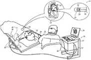
ここで図面を参照し、最初に図1を参照すると、この図は、開示される本発明の実施形態に従って構築され、動作可能である、電気的活動を評価し、生体対象の心臓12に対して診察及び治療手技を実施するためのシステム10を描図したものである。このシステムは、患者の血管系を通して、心臓12の心房・心室又は血管構造内に操作者16によって経皮的に挿入されるカテーテル14を備えている。通常、医師である操作者16は、カテーテルの遠位先端部18を、心臓壁、例えばアブレーション標的部位と接触させる。その開示が本明細書に参照により組み込まれる、米国特許第6,226,542号及び同第6,301,496号、並びに同一出願人による米国特許第6,892,091号に開示されている方法に従って、電気的活性化マップが作成され得る。システム10の要素を具現化する1つの市販の製品は、Biosense Webster,Inc.(3333 Diamond Canyon Road,Diamond Bar,CA 91765)より入手可能な、CARTO(登録商標)3システムとして入手可能である。このシステムは、本明細書に記載されている本発明の原理が具現化されるように、当業者が修正を施すことができる。 Referring now to the drawings, and first to FIG. 1, which is constructed and operable in accordance with the disclosed embodiments of the present invention to evaluate electrical activity, 1 illustrates a system 10 for performing a medical examination and treatment procedure. The system includes a catheter 14 which is inserted percutaneously by an
例えば、電気的活性化マップの評価によって異常と判定された領域は、例えば、心筋に高周波エネルギーを加える遠位先端部18の1つ又は2つ以上の電極に、カテーテル内のワイヤを通して高周波電流を流すこと等により熱エネルギーを加えることによってアブレーションを行うことができる。エネルギーは組織に吸収され、組織を電気的興奮性が永久に失われる点(一般的には約60℃超)まで加熱する。成功すると、この手技により、心組織内に非伝導性の損傷部位が形成され、この損傷部位が不整脈を発生させる異常な電気経路を遮断する。本発明の原理を異なる心室に適用することによって、多数の様々な心不整脈を診断し、治療することができる。 For example, a region determined to be abnormal by the evaluation of the electrical activation map may include, for example, applying high frequency current through a wire in a catheter to one or more electrodes of the
カテーテル14は通常、アブレーションを行うために操作者16が必要に応じてカテーテルの遠位端を方向転換すること、位置決めすること、及び方向付けることを可能にする好適な制御部を有するハンドル20を備えている。操作者16を補助するため、カテーテル14の遠位部分には、コンソール24内に配置されたプロセッサ22に信号を供給する位置センサ(図示せず)が収容されている。プロセッサ22は、以下に記載するいくつかの処理機能を果たし得る。 Catheter 14 typically includes a
アブレーションエネルギー及び電気信号を、遠位先端部18に又は遠位先端部18の付近に配置される1つ又は複数のアブレーション電極32を通して、コンソール24に至るケーブル34を介し、心臓12へ又は心臓12から、伝えることができる。ペーシング信号及び他の制御信号は、コンソール24から、ケーブル34及び電極32を通して、心臓12へと伝えることができる。感知電極33は、同様にコンソール24にも接続され、アブレーション電極32の間に配設されて、ケーブル34と接続している。 Ablation energy and electrical signals are transmitted to or from the
ワイヤ接続部35はコンソール24を、身体表面の電極30と、カテーテル14の位置座標及び配向座標を測定するための位置決定サブシステムの他の構成要素と、に連結する。プロセッサ22又は他のプロセッサ(図示せず)は、位置決定サブシステムの要素であってよい。電極32及び体表面電極30は、参照により本明細書に組み込まれる、米国特許第7,536,218号(Govariら)に教示されるように、アブレーション部位での組織のインピーダンスを測定するために使用することができる。温度センサ(図示せず)、典型的には、熱電対又はサーミスタは、電極32の各々の上に、又は電極32の各々の付近に載置され得る。 A
コンソール24には通常、1つ又は複数のアブレーション電力発生装置25が収容されている。カテーテル14は、例えば、高周波エネルギー、超音波エネルギー、及びレーザー生成光エネルギー等の任意の既知のアブレーション技術を用いて、心臓にアブレーションエネルギーを伝導するように、適合させることができる。このような方法は、参照によって本明細書に組み込まれる、本願と同一譲受人に譲渡された米国特許第6,814,733号、同第6,997,924号、及び同第7,156,816号に開示されている。 The
一実施形態において、この位置決めサブシステムは、磁場生成コイル28を使用して、既定の作業体積内に磁場を生成し、カテーテルにおけるこれらの磁場を検知することによって、カテーテル14の位置及び向きを判定する、磁気位置追跡の配置構成を含む。位置決めサブシステムは、参照により本明細書に組み込まれる米国特許第7,756,576号、及び上記の米国特許第7,536,218号に記載されている。 In one embodiment, the positioning subsystem determines the position and orientation of catheter 14 by generating magnetic fields within a predetermined working volume using magnetic field generating coils 28 and sensing these magnetic fields at the catheter. The configuration of the magnetic position tracking. The positioning subsystem is described in U.S. Patent No. 7,756,576, which is incorporated herein by reference, and in the above-mentioned U.S. Patent No. 7,536,218.
上述のように、カテーテル14は、コンソール24に連結されることによって、操作者16が、カテーテル14の機能を観察し、調節することを可能にする。コンソール24は、プロセッサ、好ましくは適当な信号処理回路を有するコンピュータを含む。プロセッサは、モニタ29を駆動するように連結されている。信号処理回路は、通常、カテーテル14からの信号を、受信、増幅、フィルタリング、及びデジタル化するが、そのような信号には、カテーテル14の遠位側に設置された、電気、温度、及び接触力センサのようなセンサ、並びに複数の場所感知電極(図示せず)により生成される信号が含まれる。デジタル化された信号は、コンソール24及び位置決めシステムによって受信されかつ使用され、カテーテル14の位置及び配向を計算し、電極からの電気信号を分析する。 As mentioned above, the catheter 14 is coupled to the
電気解剖学的マップを生成するために、プロセッサ22は通常、電気解剖学的マップ生成器、画像登録プログラム、及び画像又はデータ分析プログラムを備え、且つモニタ29上にグラフィカル情報を提示するグラフィカルユーザーインターフェイスをも備える。 To generate an electroanatomical map, the
簡略化のため図には示されていないが、通常、システム10には、他の要素も含まれる。例えば、システム10は、心電図(ECG)モニタを含み得るが、このECGモニタは、ECG同期信号をコンソール24に供給するために、1つ又は2つ以上の身体表面電極から信号を受信するように連結される。また、上に述べたように、システム10は通常、基準位置センサをも含むが、基準位置センサは、患者の身体の外側に取り付けられた、体位外貼付式基準パッチ上、又は心臓12に挿入され、心臓12に対して固定位置に維持された、体内配置式カテーテル上のいずれかに配置される。カテーテル14に液体を通して循環させるための、従来のポンプ及びラインが、アブレーション部位を冷却するために提供される。システム10は、画像データを外部MRIユニット等のような画像診断法から受信することもできるし、画像生成及び表示の目的で、プロセッサ22に統合され得る又はプロセッサ22により起動され得る画像プロセッサを具備することもできる。 Although not shown in the figures for simplicity, the system 10 typically also includes other elements. For example, system 10 may include an electrocardiogram (ECG) monitor, which receives signals from one or more body surface electrodes to provide ECG synchronization signals to console 24. Be linked. Also, as noted above, the system 10 typically also includes a reference position sensor, which may be inserted on an extracorporeal self-adhesive reference patch attached to the outside of the patient's body or into the
ここで図2を参照すると、図2は、本発明の実施形態に従って評価される組織39と接触しているカテーテル37の遠位部分の概略図である。超音波変換器41は、カテーテル37内に設置され、接触力センサ43は、遠位先端45に、又はその近くに配置される。カテーテル37は、組織表面49に対してほぼ垂直な方向47において往復運動し、それにより、少なくとも先端45の直下にある組織39の領域に圧迫及び減圧する。カテーテル37の偏位は、1〜10Hzの周波数で生じ、組織39を0.3〜0.5mm及び最大5mm圧迫するのに十分な力で実施される。カテーテル37の往復運動は、機械的作動装置51によって駆動され得る。アルゴリズムの感度を増加させるために、飛行時間反射の実用範囲は、その中にカテーテル37が見られる室に従って制限される。例えば、右心房に対する反射の飛行時間の可能な範囲は、0.25〜7mmの組織厚と対応し、超音波変換器の全範囲又は左心室を評価するために必要とされる範囲よりもはるかに少ない。左心室では、反射の飛行時間の可能な範囲は、2〜20mmの組織厚に対応する。 Referring now to FIG. 2, FIG. 2 is a schematic diagram of a distal portion of a
接触力センサ43に関する好適なセンサは、本出願と同一の出願人による米国特許出願公開第2012/0259194号及び同第2014/0100563号に記載されており、それらは参照により本明細書に組み込まれる。 Suitable sensors for the
超音波変換器41は、10MHzの典型的な速度で、Mモードで遠心超音波パルス53を放つ既知の単結晶型であってもよい。パルス53は、組織界面55から反射し、次いで、求心性パルス57として検出される。組織39は、心室の壁であってもよく、組織界面55は、その重なる心外膜であってもよい。パルス53、57の飛行時間は、先端45が接近し、組織界面55から後退することに応じて変化する。 The
他の反射もまた、超音波変換器41によって検出され得る。これらは、反射界面59、61により、図2に例示されている。それぞれの界面59、61と関連付けられる飛行時間の変化は、組織界面55に関連付けられる飛行時間の変化よりも、接触力並びにカテーテル37の運動とあまり相関しない。組織界面55は、カテーテル37の運動との最も高い相関性を有する飛行時間を有するように、候補となる反射の中から識別することができる。 Other reflections may also be detected by the
ここで図3を参照すると、図3は、本発明の実施形態に従って、超音波変換器を使用して飛行時間により示される、カテーテル先端の接触力と組織界面の運動との間の相関性の予測グラフ例である。追跡63は、組織表面に対して垂直なカテーテル先端の並進運動を表す。追跡65、67、69は、組織界面55、59、61(図2)に関連付けられる飛行時間を表す。検査から、追跡65の形態は、追跡63のものとよく相関するが、追跡67、69は、追跡63と相関しないように見えることが明らかである。これは、標準的な相関式を使用して、確認することができる。例えば、
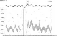
ここで図4を参照すると、図4は、本発明の実施形態による、図3に類似のグラフ表現である。Mモードで動作する超音波プローブの接触力は、追跡71で示される。反射を処理して、それらのそれぞれの追跡71との統計的相関性を判定し、それらのそれぞれの追跡71との相関性に従って、反射は強調されたか、又は強調を抑えられた。追跡71との比較的高い相関性を有する追跡73は、強調するために拡大され、操作者が、他の反射からそれを容易に区別することを可能にする。他の反射は、強調を抑えられた。 Referring now to FIG. 4, FIG. 4 is a graphical representation similar to FIG. 3, according to an embodiment of the present invention. The contact force of the ultrasonic probe operating in the M mode is indicated by tracking 71. The reflections were processed to determine their statistical correlation with their respective traces 71, and the reflections were either enhanced or de-emphasized according to their correlation with the respective traces 71. The track 73, which has a relatively high correlation with the track 71, is enlarged for emphasis and allows the operator to easily distinguish it from other reflections. Other reflections were deemphasized.
代替実施形態
この実施形態は、ここでは、心臓の周期運動の全て又は一部において、信頼がおけることを除いて、前述の実施形態と同様であり、カテーテルは、心臓が収縮するのに応じて求心方向に促されるとき、転位に抵抗するため、カテーテルと接触しているときに、異なる接触力を生み出す。Alternative Embodiment This embodiment is now similar to the previous embodiment, except that it is reliable in all or part of the cyclic movement of the heart, and the catheter responds as the heart contracts. When prompted in a centripetal direction, it creates a different contact force when in contact with the catheter to resist displacement.
再び図2を参照して、心臓の機能的能力が正常に近い場合、組織39自体の運動は、信頼できるデータを生成するのに十分であり、作動装置51は、除外又は停止されてもよい。しかしながら、局所的又は全体的な機能的能力が減少している場合、例えば、鬱血性心不全又はある特定の不整脈の場合、カテーテル37との循環的接触力を十分に生成するために、作動装置51を用いた心臓運動の増大が必要とされ得る。そのような場合、作動装置51は、心臓運動と同期されてもよく、好適なコントローラ(図示せず)又はプロセッサ22(図1)を使用して、低減したインパルス電力で動作され得る。例えば、作動装置のタイミングは、心電図信号、及びカテーテル37内の圧力センサ(図示せず)の測定値から得られる心臓内圧力力学に従って、例えば、プロセッサ22によって動的に制御されたそのインパルス電力と同期され得る。 Referring again to FIG. 2, if the functional capacity of the heart is near normal, the movement of the
動作
ここで図5を参照すると、図5は、本発明の実施形態に従って、超音波及び力測定を使用して組織厚を判定する方法のフローチャートである。そのプロセス工程は、提示の明瞭性のために、特定の線形順序で示される。しかしながら、それらのプロセス工程の多くは、並列的に、非同期的に、又は異なる順序で実行され得ることが明白であろう。当業者であれば、プロセスは、別の方法としては、例えば、状態図において、相互関連状態又は事象の数として表現され得ることが理解されるであろう。更には、例示されている全てのプロセス工程が、この方法の実装に必要とされるとは限らない場合もある。Operation Referring now to FIG. 5, FIG. 5 is a flowchart of a method for determining tissue thickness using ultrasound and force measurement, according to an embodiment of the present invention. The process steps are shown in a specific linear order for clarity of presentation. However, it will be apparent that many of those process steps may be performed in parallel, asynchronously, or in a different order. Those skilled in the art will appreciate that a process may alternatively be represented as a number of interrelated states or events, for example, in a state diagram. Moreover, not all illustrated process steps may be required to implement the method.
初期工程75では、心室のカテーテル処置が、慣習的に達成される。その先端における、又はその近くにある接触力センサ及び超音波変換器を有する心臓カテーテルは、目的とする標的部位に接触している心室に導入される。典型的には、標的部位は、心室の心内膜表面であり、アブレーションを受ける。カテーテルは、一般的に、制御機構、例えば、システム10の構成要素(図1)とともに使用するためにアブレーション電極が備わっている。 In an
次に、工程77では、超音波変換器及び作動装置は、上述のように、標的組織に対してカテーテルを往復運動させるように作動される。変換器は、典型的には、Mモードで動作される。 Next, in
次に、工程79では、超音波データは、カテーテルが、典型的には約2秒間、往復運動している間に取得される。作動装置によって加えられる接触力は、画像取得の間に記録される。 Next, at
次に、工程81では、候補となる反射データ、例えば、界面線は、工程79で取得された画像データから識別及び選択される。これは、好適に実行されるプロセッサによって自動的に実施され得る。 Next, in
次に、工程83では、工程81で選択されたデータを工程79で取得された接触力データと相関させる。上で延べたように、相関の任意の好適な方法が、工程83に適用され得る。 Next, in
次に、決定工程85では、評価されるべき更なる候補となるデータが残存するかどうかが判定される。判定が肯定である場合、制御が、別の反復のために工程81に戻る。 Next, in
決定工程85における判定が否定である場合、制御が工程87に進み、接触力データと最も大きい相関性を有する候補が候補の中から選択される。選択された候補は、外壁、即ち、心室の心外膜表面を識別するように処理される。 If the determination in
次に、工程89では、心室の心内膜表面での接触部位と選択された候補との間の距離が、従来の超音波技法を使用して、例えば、適切な飛行時間を判定することによって測定される。この距離は、カテーテルとの接触点における組織厚である。 Next, in
次いで、最終工程91では、アブレーションパラメータ、例えば、発電電圧及び持続時間を、工程89で測定された組織厚に従って設定し、アブレーション電極は、所望の治療手技を実施するように作動される。 Then, in a
本発明は、上文に具体的に図示及び説明したものに限定されないことが、当業者には理解されよう。むしろ、本発明の範囲には、本明細書で上述した様々な特徴の組み合わせと部分的組み合わせの双方、並びに先行技術にはないそれらの変形形態及び修正形態が含まれ、これらは、上記の説明を読めば当業者に想到されるであろう。 It will be appreciated by those skilled in the art that the present invention is not limited to what has been particularly shown and described above. Rather, the scope of the present invention includes both combinations and subcombinations of the various features described herein above, as well as variations and modifications thereof that are not in the prior art, which are not covered by the foregoing description. Will be reminded to those skilled in the art.
〔実施の態様〕
(1) 方法であって、
遠位セグメントを有するカテーテルを、対象の体内の空洞の壁と接触するように挿入する工程であって、前記空洞が内面及び外面を有し、前記カテーテルの前記遠位セグメントに接触力センサ及び超音波変換器が備わっている、挿入する工程と、
前記変換器を作動させて、前記空洞の前記壁から超音波反射データを取得する工程と、
前記変換器の作動中に、前記空洞の前記壁に対して、前記カテーテルを往復運動させ、前記カテーテルと前記空洞の前記壁との間の接触力を測定する工程と、
前記反射データを前記接触力と相関させる工程と、
前記接触力との最も高い相関性を有する1組の前記相関させた反射データを識別する工程と、
前記内面と前記識別された1組の前記反射データとの間の組織厚を、それらの間の飛行時間に従って判定する工程と、を含む、方法。
(2) 前記組織厚に応じて前記空洞の前記壁をアブレーションすることを更に含む、実施態様1に記載の方法。
(3) 前記変換器の作動が、Mモードで実施される、実施態様1に記載の方法。
(4) 前記カテーテルの往復運動が、前記内面に対して垂直に実施される、実施態様1に記載の方法。
(5) 前記空洞が、前記対象の心臓の室であり、前記カテーテルの往復運動が、前記カテーテルを往復運動させる前記心臓の周期運動によって実施される、実施態様1に記載の方法。(Embodiment)
(1) a method,
Inserting a catheter having a distal segment into contact with a wall of a cavity in a subject's body, wherein the cavity has an inner surface and an outer surface, and a contact force sensor and an ultra-stress on the distal segment of the catheter. An insertion step provided with a sound wave transducer;
Actuating the transducer to acquire ultrasound reflection data from the wall of the cavity;
Reciprocating the catheter relative to the wall of the cavity during operation of the transducer and measuring a contact force between the catheter and the wall of the cavity;
Correlating the reflection data with the contact force;
Identifying a set of the correlated reflection data having the highest correlation with the contact force;
Determining a tissue thickness between the inner surface and the identified set of reflection data according to a time of flight therebetween.
2. The method of embodiment 1, further comprising ablating the wall of the cavity in response to the tissue thickness.
(3) The method of embodiment 1, wherein the operation of the converter is performed in M mode.
(4) The method according to embodiment 1, wherein the reciprocating movement of the catheter is performed perpendicular to the inner surface.
5. The method of claim 1, wherein the cavity is a chamber of the subject's heart and the reciprocating motion of the catheter is performed by a cyclic motion of the heart reciprocating the catheter.
(6) 前記カテーテルの往復運動が、前記カテーテルに連係された作動装置によって実施される、実施態様1に記載の方法。
(7) 前記作動装置を前記対象の心臓の周期運動と同期させることを更に含む、実施態様6に記載の方法。
(8) 心臓内流体圧力に従って、前記作動装置のインパルス電力を調節することを更に含む、実施態様6に記載の方法。
(9) 前記カテーテルの往復運動が、前記空洞の前記壁を0.3〜0.5mm圧迫するのに十分な力で実施される、実施態様1に記載の方法。
(10) 前記カテーテルの往復運動が、1〜10Hzの周波数で実施される、実施態様1に記載の方法。The method of claim 1, wherein the reciprocating movement of the catheter is performed by an actuator associated with the catheter.
Aspect 7. The method of aspect 6, further comprising synchronizing the actuator with a periodic motion of the subject's heart.
The method of claim 6, further comprising adjusting the impulse power of the actuator according to the intracardiac fluid pressure.
The method of claim 1, wherein the reciprocating movement of the catheter is performed with a force sufficient to squeeze the wall of the cavity 0.3-0.5 mm.
(10) The method according to embodiment 1, wherein the reciprocating movement of the catheter is performed at a frequency of 1 to 10 Hz.
(11) 装置であって、
対象の体内の空洞の壁と接触するような挿入のために構成される遠位セグメントを有するカテーテルであって、前記空洞が内面及び外面を有する、カテーテルと、
前記遠位セグメント内に配置された接触力センサ及び超音波変換器と、
前記変換器を作動させて、前記空洞の前記壁から超音波反射データを取得するために動作可能な超音波発生装置と、
前記変換器の動作中に、前記空洞の前記壁に対して、前記カテーテルを往復運動させるために動作可能な作動装置と、
前記接触力センサと連係され、前記カテーテルと前記空洞の前記壁との間の接触力を測定するために動作可能な電気回路と、
前記電気回路及び前記変換器と連係され、前記反射データを受信するプロセッサであって、前記接触力との最も高い相関性を有する1組の前記相関させた反射データを識別し、前記内面と前記識別された1組の前記反射データとの間の組織厚を、それらの間の飛行時間に従って判定するために動作可能である、プロセッサと、を備える、装置。
(12) 前記空洞の前記壁をアブレーションするために動作可能なアブレータを更に備え、前記アブレータが、前記組織厚に応じて調整可能である、実施態様11に記載の装置。
(13) 前記超音波発生装置が、前記変換器をMモードで作動させるために動作可能である、実施態様11に記載の装置。
(14) 前記作動装置が、前記内面に対して垂直に、前記カテーテルを往復運動させるように動作可能である、実施態様11に記載の装置。
(15) 前記作動装置が、前記空洞の前記壁を0.3〜0.5mm圧迫するのに十分な力で、前記カテーテルを往復運動させるように動作可能である、実施態様11に記載の装置。(11) An apparatus,
A catheter having a distal segment configured for insertion into contact with a wall of a cavity in a body of a subject, wherein the cavity has an inner surface and an outer surface;
A contact force sensor and an ultrasonic transducer disposed within the distal segment;
An ultrasonic generator operable to activate the transducer to acquire ultrasonic reflection data from the wall of the cavity;
An actuator operable to reciprocate the catheter relative to the wall of the cavity during operation of the transducer;
An electrical circuit associated with the contact force sensor and operable to measure a contact force between the catheter and the wall of the cavity;
A processor coupled to the electrical circuit and the transducer for receiving the reflection data, the processor identifying a set of the correlated reflection data having a highest correlation with the contact force; A processor operable to determine a tissue thickness between the identified set of reflection data and the time of flight between them.
12. The apparatus of claim 11, further comprising an ablator operable to ablate the wall of the cavity, wherein the ablator is adjustable according to the tissue thickness.
(13) The apparatus according to embodiment 11, wherein the ultrasonic generator is operable to operate the transducer in M mode.
The apparatus of claim 11, wherein the actuator is operable to reciprocate the catheter perpendicular to the inner surface.
15. The device of embodiment 11, wherein the actuator is operable to reciprocate the catheter with a force sufficient to squeeze the wall of the cavity by 0.3-0.5 mm. .
(16) 前記作動装置が、前記カテーテルに、1〜10Hzの周波数で実施される往復運動をさせるように動作可能である、実施態様11に記載の装置。16. The apparatus of claim 11, wherein the actuator is operable to cause the catheter to reciprocate, which is performed at a frequency of 1-10 Hz.
Claims (7)
Translated fromJapanese対象の体内の空洞の壁と接触するような挿入のために構成される遠位セグメントを有するカテーテルであって、前記空洞が内面及び外面を有する、カテーテルと、
前記遠位セグメント内に配置された接触力センサ及び超音波変換器と、
前記超音波変換器を作動させて、前記空洞の前記壁における、前記内面からの距離が互いに異なる複数の組織界面から超音波反射データを取得するために動作可能な超音波発生装置と、
前記接触力センサと連係され、前記カテーテルと前記空洞の前記壁との間の接触力を測定するために動作可能な電気回路と、
前記電気回路及び前記超音波変換器と連係され、前記超音波反射データを受信するプロセッサであって、前記複数の組織界面から取得された前記超音波反射データの内で、前記接触力との最も高い相関性を有する超音波反射データを識別し、前記内面と前記識別された超音波反射データを取得した組織界面との間の組織厚を、それらの間の飛行時間に従って判定するために動作可能である、プロセッサと、を備える、装置。A device,
A catheter having a distal segment configured for insertion into contact with a wall of a cavity in a body of a subject, wherein the cavity has an inner surface and an outer surface;
A contact force sensor and an ultrasonic transducer disposed within the distal segment;
By operating the ultrasonic transducer, in the wall of the cavity, an ultrasonic generator operable to obtain ultrasonic reflection data from a plurality of tissue interfaces different in distance from the inner surface,
An electrical circuit associated with the contact force sensor and operable to measure a contact force between the catheter and the wall of the cavity;
A processor that is linked to the electric circuit and the ultrasonic transducer and receives the ultrasonic reflection data, and among the ultrasonic reflection data obtained from the plurality of tissue interfaces, Operable to identify highly correlated ultrasound reflection data and determine the tissue thickness between the inner surface and the tissue interface from which the identified ultrasound reflection data was obtained, according to the time of flight therebetween. An apparatus comprising: a processor.
Applications Claiming Priority (2)
| Application Number | Priority Date | Filing Date | Title |
|---|---|---|---|
| US14/585,788US10327734B2 (en) | 2014-12-30 | 2014-12-30 | Measurement of tissue thickness using ultrasound and force measurements |
| US14/585,788 | 2014-12-30 |
Related Parent Applications (1)
| Application Number | Title | Priority Date | Filing Date |
|---|---|---|---|
| JP2015255769ADivisionJP6621660B2 (en) | 2014-12-30 | 2015-12-28 | Tissue thickness measurement using ultrasonic and force measurements |
Publications (2)
| Publication Number | Publication Date |
|---|---|
| JP2020032252Atrue JP2020032252A (en) | 2020-03-05 |
| JP6866458B2 JP6866458B2 (en) | 2021-04-28 |
Family
ID=54936942
Family Applications (2)
| Application Number | Title | Priority Date | Filing Date |
|---|---|---|---|
| JP2015255769AActiveJP6621660B2 (en) | 2014-12-30 | 2015-12-28 | Tissue thickness measurement using ultrasonic and force measurements |
| JP2019209439AActiveJP6866458B2 (en) | 2014-12-30 | 2019-11-20 | Equipment for measuring tissue thickness using ultrasound and force measurements |
Family Applications Before (1)
| Application Number | Title | Priority Date | Filing Date |
|---|---|---|---|
| JP2015255769AActiveJP6621660B2 (en) | 2014-12-30 | 2015-12-28 | Tissue thickness measurement using ultrasonic and force measurements |
Country Status (8)
| Country | Link |
|---|---|
| US (1) | US10327734B2 (en) |
| EP (1) | EP3050499B1 (en) |
| JP (2) | JP6621660B2 (en) |
| CN (1) | CN105726065B (en) |
| AU (1) | AU2015268763B2 (en) |
| CA (1) | CA2916100A1 (en) |
| ES (1) | ES2735725T3 (en) |
| IL (1) | IL243180B (en) |
Families Citing this family (9)
| Publication number | Priority date | Publication date | Assignee | Title |
|---|---|---|---|---|
| US10034653B2 (en)* | 2016-01-11 | 2018-07-31 | Biosense Webster (Israel) Ltd. | Tissue depth estimation using gated ultrasound and force measurements |
| US10646197B2 (en) | 2016-07-06 | 2020-05-12 | Biosense Webster (Israel) Ltd. | Ascertaining tissue thickness |
| KR102721645B1 (en) | 2016-09-27 | 2024-10-25 | 삼성메디슨 주식회사 | Ultrasound diagnostic apparatus and operating method for the same |
| US11147610B2 (en)* | 2017-02-10 | 2021-10-19 | Biosense Webster (Israel) Ltd. | Tissue thickness using pulsed power |
| US10751121B2 (en) | 2017-06-29 | 2020-08-25 | Biosense Webster (Israel) Ltd. | Ultrasound transducers on predetermined radii of balloon catheter |
| US11583249B2 (en)* | 2017-09-08 | 2023-02-21 | Biosense Webster (Israel) Ltd. | Method and apparatus for performing non-fluoroscopic transseptal procedure |
| JP7202263B2 (en) | 2019-06-24 | 2023-01-11 | 朝日インテック株式会社 | Catheters, catheter sets, and medical devices |
| US20210085215A1 (en)* | 2019-09-22 | 2021-03-25 | Biosense Webster (Israel) Ltd. | Ecg-based cardiac wall thickness estimation |
| EP4196002A4 (en)* | 2020-08-13 | 2024-08-14 | Otago Innovation Limited | DENTAL DEVICE AND METHOD |
Citations (4)
| Publication number | Priority date | Publication date | Assignee | Title |
|---|---|---|---|---|
| US6494840B1 (en)* | 2000-07-31 | 2002-12-17 | The Hong Kong Polytechnic University | Portable ultrasonic palpation system |
| US20120004547A1 (en)* | 2009-01-14 | 2012-01-05 | Koninklijke Philips Electronics N.V. | Monitoring apparatus for monitoring an ablation procedure |
| US20130190726A1 (en)* | 2010-04-30 | 2013-07-25 | Children's Medical Center Corporation | Motion compensating catheter device |
| US20140142438A1 (en)* | 2012-11-19 | 2014-05-22 | Biosense Webster (Israel), Ltd. | Using location and force measurements to estimate tissue thickness |
Family Cites Families (26)
| Publication number | Priority date | Publication date | Assignee | Title |
|---|---|---|---|---|
| AU710236B2 (en) | 1996-01-08 | 1999-09-16 | Biosense, Inc. | Cardiac electro-mechanics |
| US5957943A (en)* | 1997-03-05 | 1999-09-28 | Ethicon Endo-Surgery, Inc. | Method and devices for increasing ultrasonic effects |
| US6226542B1 (en) | 1998-07-24 | 2001-05-01 | Biosense, Inc. | Three-dimensional reconstruction of intrabody organs |
| US6301496B1 (en) | 1998-07-24 | 2001-10-09 | Biosense, Inc. | Vector mapping of three-dimensionally reconstructed intrabody organs and method of display |
| US6892091B1 (en) | 2000-02-18 | 2005-05-10 | Biosense, Inc. | Catheter, method and apparatus for generating an electrical map of a chamber of the heart |
| US6554774B1 (en) | 2000-03-23 | 2003-04-29 | Tensys Medical, Inc. | Method and apparatus for assessing hemodynamic properties within the circulatory system of a living subject |
| CA2333224A1 (en) | 2001-01-31 | 2002-07-31 | University Technologies International Inc. | Non-invasive diagnostic method and apparatus for musculoskeletal systems |
| US6814733B2 (en) | 2002-01-31 | 2004-11-09 | Biosense, Inc. | Radio frequency pulmonary vein isolation |
| US7578789B2 (en)* | 2002-08-08 | 2009-08-25 | Echosens | Device and method for measuring the elasticity of a human or animal organ |
| US6997924B2 (en) | 2002-09-17 | 2006-02-14 | Biosense Inc. | Laser pulmonary vein isolation |
| US7156816B2 (en) | 2002-11-26 | 2007-01-02 | Biosense, Inc. | Ultrasound pulmonary vein isolation |
| JP4189840B2 (en) | 2003-10-20 | 2008-12-03 | 独立行政法人産業技術総合研究所 | Apparatus and program for estimating viscoelasticity of soft tissue using ultrasound |
| US7604601B2 (en) | 2005-04-26 | 2009-10-20 | Biosense Webster, Inc. | Display of catheter tip with beam direction for ultrasound system |
| US7536218B2 (en) | 2005-07-15 | 2009-05-19 | Biosense Webster, Inc. | Hybrid magnetic-based and impedance-based position sensing |
| US7877128B2 (en) | 2005-08-02 | 2011-01-25 | Biosense Webster, Inc. | Simulation of invasive procedures |
| US8583220B2 (en) | 2005-08-02 | 2013-11-12 | Biosense Webster, Inc. | Standardization of catheter-based treatment for atrial fibrillation |
| US7756576B2 (en) | 2005-08-26 | 2010-07-13 | Biosense Webster, Inc. | Position sensing and detection of skin impedance |
| BRPI0618421A2 (en) | 2005-10-27 | 2011-08-30 | St Jude Medical Atrial Fibrill | systems and methods for electrode contact evaluation |
| US8320711B2 (en) | 2007-12-05 | 2012-11-27 | Biosense Webster, Inc. | Anatomical modeling from a 3-D image and a surface mapping |
| CA2703347C (en) | 2009-05-08 | 2016-10-04 | Endosense Sa | Method and apparatus for controlling lesion size in catheter-based ablation treatment |
| US8374670B2 (en) | 2010-01-22 | 2013-02-12 | Biosense Webster, Inc. | Catheter having a force sensing distal tip |
| AU2011284300A1 (en) | 2010-07-25 | 2013-03-14 | Syneron Medical Ltd. | A method and apparatus for measuring the thickness of adipose tissue |
| US8628473B2 (en) | 2011-04-13 | 2014-01-14 | St. Jude Medical, Inc. | Acoustic transducer for pulse-echo monitoring and control of thermally ablative lesioning in layered and nonlayered tissues, catheter contact monitoring, tissue thickness measurement and pre-pop warning |
| US8545408B2 (en) | 2011-05-23 | 2013-10-01 | St. Jude Medical, Inc. | Combination catheter for forward and side lesioning with acoustic lesion feedback capability |
| US9615815B2 (en) | 2012-09-28 | 2017-04-11 | Clemson University Research Foundation | Devices that cooperate with ultrasound probes for muscoskeletal evaluations and related systems and methods |
| US11096741B2 (en) | 2012-10-10 | 2021-08-24 | Biosense Webster (Israel) Ltd. | Ablation power control based on contact force |
- 2014
- 2014-12-30USUS14/585,788patent/US10327734B2/enactiveActive
- 2015
- 2015-12-16AUAU2015268763Apatent/AU2015268763B2/ennot_activeCeased
- 2015-12-17ILIL243180Apatent/IL243180B/enactiveIP Right Grant
- 2015-12-22CACA2916100Apatent/CA2916100A1/ennot_activeAbandoned
- 2015-12-23EPEP15202371.9Apatent/EP3050499B1/enactiveActive
- 2015-12-23ESES15202371Tpatent/ES2735725T3/enactiveActive
- 2015-12-28JPJP2015255769Apatent/JP6621660B2/enactiveActive
- 2015-12-29CNCN201511010191.0Apatent/CN105726065B/enactiveActive
- 2019
- 2019-11-20JPJP2019209439Apatent/JP6866458B2/enactiveActive
Patent Citations (6)
| Publication number | Priority date | Publication date | Assignee | Title |
|---|---|---|---|---|
| US6494840B1 (en)* | 2000-07-31 | 2002-12-17 | The Hong Kong Polytechnic University | Portable ultrasonic palpation system |
| US20120004547A1 (en)* | 2009-01-14 | 2012-01-05 | Koninklijke Philips Electronics N.V. | Monitoring apparatus for monitoring an ablation procedure |
| JP2012515013A (en)* | 2009-01-14 | 2012-07-05 | コーニンクレッカ フィリップス エレクトロニクス エヌ ヴィ | Monitoring device to monitor ablation treatment |
| US20130190726A1 (en)* | 2010-04-30 | 2013-07-25 | Children's Medical Center Corporation | Motion compensating catheter device |
| US20140142438A1 (en)* | 2012-11-19 | 2014-05-22 | Biosense Webster (Israel), Ltd. | Using location and force measurements to estimate tissue thickness |
| JP2014100568A (en)* | 2012-11-19 | 2014-06-05 | Biosense Webster (Israel) Ltd | Use of position and force measurements to estimate tissue thickness |
Also Published As
| Publication number | Publication date |
|---|---|
| EP3050499B1 (en) | 2019-05-15 |
| US10327734B2 (en) | 2019-06-25 |
| CA2916100A1 (en) | 2016-06-30 |
| AU2015268763B2 (en) | 2019-10-24 |
| CN105726065A (en) | 2016-07-06 |
| JP6621660B2 (en) | 2019-12-18 |
| ES2735725T3 (en) | 2019-12-20 |
| CN105726065B (en) | 2021-04-09 |
| AU2015268763A1 (en) | 2016-07-14 |
| JP6866458B2 (en) | 2021-04-28 |
| US20160183915A1 (en) | 2016-06-30 |
| EP3050499A1 (en) | 2016-08-03 |
| JP2016123868A (en) | 2016-07-11 |
| IL243180B (en) | 2019-03-31 |
Similar Documents
| Publication | Publication Date | Title |
|---|---|---|
| JP6866458B2 (en) | Equipment for measuring tissue thickness using ultrasound and force measurements | |
| JP6294548B2 (en) | A device for the geometric measurement of the electric dipole density of the heart wall. | |
| JP5829526B2 (en) | Monitoring device to monitor ablation treatment | |
| JP6246525B2 (en) | Machine learning in the determination of catheter electrode contact | |
| US9220924B2 (en) | System and method for energy delivery to tissue while monitoring position, lesion depth, and wall motion | |
| US9033885B2 (en) | System and method for energy delivery to tissue while monitoring position, lesion depth, and wall motion | |
| JP6929216B2 (en) | Systems and related methods for ultrasonic ablation or monitoring of cardiac zones | |
| JP2012500657A (en) | Detection device for detecting an object | |
| US11298568B2 (en) | System and method for energy delivery to tissue while monitoring position, lesion depth, and wall motion | |
| JP6018341B2 (en) | Monitoring device | |
| CN103220982B (en) | Apparatus for detecting properties of objects | |
| JP6827816B2 (en) | Tissue depth estimation using gate-controlled ultrasound and force measurements |
Legal Events
| Date | Code | Title | Description |
|---|---|---|---|
| A621 | Written request for application examination | Free format text:JAPANESE INTERMEDIATE CODE: A621 Effective date:20191120 | |
| A977 | Report on retrieval | Free format text:JAPANESE INTERMEDIATE CODE: A971007 Effective date:20200923 | |
| A131 | Notification of reasons for refusal | Free format text:JAPANESE INTERMEDIATE CODE: A131 Effective date:20201013 | |
| A521 | Request for written amendment filed | Free format text:JAPANESE INTERMEDIATE CODE: A523 Effective date:20210108 | |
| TRDD | Decision of grant or rejection written | ||
| A01 | Written decision to grant a patent or to grant a registration (utility model) | Free format text:JAPANESE INTERMEDIATE CODE: A01 Effective date:20210330 | |
| A61 | First payment of annual fees (during grant procedure) | Free format text:JAPANESE INTERMEDIATE CODE: A61 Effective date:20210407 | |
| R150 | Certificate of patent or registration of utility model | Ref document number:6866458 Country of ref document:JP Free format text:JAPANESE INTERMEDIATE CODE: R150 | |
| R250 | Receipt of annual fees | Free format text:JAPANESE INTERMEDIATE CODE: R250 | |
| R250 | Receipt of annual fees | Free format text:JAPANESE INTERMEDIATE CODE: R250 |