JP2020028718A - Virtual image with optical shape sensing device perspective - Google Patents
Virtual image with optical shape sensing device perspectiveDownload PDFInfo
- Publication number
- JP2020028718A JP2020028718AJP2019178921AJP2019178921AJP2020028718AJP 2020028718 AJP2020028718 AJP 2020028718AJP 2019178921 AJP2019178921 AJP 2019178921AJP 2019178921 AJP2019178921 AJP 2019178921AJP 2020028718 AJP2020028718 AJP 2020028718A
- Authority
- JP
- Japan
- Prior art keywords
- image
- shape
- virtual image
- detectable device
- virtual
- Prior art date
- Legal status (The legal status is an assumption and is not a legal conclusion. Google has not performed a legal analysis and makes no representation as to the accuracy of the status listed.)
- Granted
Links
Images


Classifications
- A—HUMAN NECESSITIES
- A61—MEDICAL OR VETERINARY SCIENCE; HYGIENE
- A61B—DIAGNOSIS; SURGERY; IDENTIFICATION
- A61B34/00—Computer-aided surgery; Manipulators or robots specially adapted for use in surgery
- A61B34/20—Surgical navigation systems; Devices for tracking or guiding surgical instruments, e.g. for frameless stereotaxis
- A—HUMAN NECESSITIES
- A61—MEDICAL OR VETERINARY SCIENCE; HYGIENE
- A61B—DIAGNOSIS; SURGERY; IDENTIFICATION
- A61B34/00—Computer-aided surgery; Manipulators or robots specially adapted for use in surgery
- A61B34/30—Surgical robots
- A—HUMAN NECESSITIES
- A61—MEDICAL OR VETERINARY SCIENCE; HYGIENE
- A61B—DIAGNOSIS; SURGERY; IDENTIFICATION
- A61B5/00—Measuring for diagnostic purposes; Identification of persons
- A61B5/06—Devices, other than using radiation, for detecting or locating foreign bodies ; Determining position of diagnostic devices within or on the body of the patient
- A61B5/065—Determining position of the probe employing exclusively positioning means located on or in the probe, e.g. using position sensors arranged on the probe
- A61B5/066—Superposing sensor position on an image of the patient, e.g. obtained by ultrasound or x-ray imaging
- A—HUMAN NECESSITIES
- A61—MEDICAL OR VETERINARY SCIENCE; HYGIENE
- A61B—DIAGNOSIS; SURGERY; IDENTIFICATION
- A61B8/00—Diagnosis using ultrasonic, sonic or infrasonic waves
- A61B8/08—Clinical applications
- A61B8/0833—Clinical applications involving detecting or locating foreign bodies or organic structures
- A61B8/0841—Clinical applications involving detecting or locating foreign bodies or organic structures for locating instruments
- A—HUMAN NECESSITIES
- A61—MEDICAL OR VETERINARY SCIENCE; HYGIENE
- A61B—DIAGNOSIS; SURGERY; IDENTIFICATION
- A61B8/00—Diagnosis using ultrasonic, sonic or infrasonic waves
- A61B8/08—Clinical applications
- A61B8/0883—Clinical applications for diagnosis of the heart
- A—HUMAN NECESSITIES
- A61—MEDICAL OR VETERINARY SCIENCE; HYGIENE
- A61B—DIAGNOSIS; SURGERY; IDENTIFICATION
- A61B8/00—Diagnosis using ultrasonic, sonic or infrasonic waves
- A61B8/08—Clinical applications
- A61B8/0891—Clinical applications for diagnosis of blood vessels
- A—HUMAN NECESSITIES
- A61—MEDICAL OR VETERINARY SCIENCE; HYGIENE
- A61B—DIAGNOSIS; SURGERY; IDENTIFICATION
- A61B8/00—Diagnosis using ultrasonic, sonic or infrasonic waves
- A61B8/12—Diagnosis using ultrasonic, sonic or infrasonic waves in body cavities or body tracts, e.g. by using catheters
- A—HUMAN NECESSITIES
- A61—MEDICAL OR VETERINARY SCIENCE; HYGIENE
- A61B—DIAGNOSIS; SURGERY; IDENTIFICATION
- A61B8/00—Diagnosis using ultrasonic, sonic or infrasonic waves
- A61B8/13—Tomography
- A61B8/14—Echo-tomography
- A—HUMAN NECESSITIES
- A61—MEDICAL OR VETERINARY SCIENCE; HYGIENE
- A61B—DIAGNOSIS; SURGERY; IDENTIFICATION
- A61B8/00—Diagnosis using ultrasonic, sonic or infrasonic waves
- A61B8/42—Details of probe positioning or probe attachment to the patient
- A61B8/4209—Details of probe positioning or probe attachment to the patient by using holders, e.g. positioning frames
- A61B8/4218—Details of probe positioning or probe attachment to the patient by using holders, e.g. positioning frames characterised by articulated arms
- A—HUMAN NECESSITIES
- A61—MEDICAL OR VETERINARY SCIENCE; HYGIENE
- A61B—DIAGNOSIS; SURGERY; IDENTIFICATION
- A61B8/00—Diagnosis using ultrasonic, sonic or infrasonic waves
- A61B8/42—Details of probe positioning or probe attachment to the patient
- A61B8/4245—Details of probe positioning or probe attachment to the patient involving determining the position of the probe, e.g. with respect to an external reference frame or to the patient
- A61B8/4254—Details of probe positioning or probe attachment to the patient involving determining the position of the probe, e.g. with respect to an external reference frame or to the patient using sensors mounted on the probe
- A—HUMAN NECESSITIES
- A61—MEDICAL OR VETERINARY SCIENCE; HYGIENE
- A61B—DIAGNOSIS; SURGERY; IDENTIFICATION
- A61B8/00—Diagnosis using ultrasonic, sonic or infrasonic waves
- A61B8/52—Devices using data or image processing specially adapted for diagnosis using ultrasonic, sonic or infrasonic waves
- A61B8/5215—Devices using data or image processing specially adapted for diagnosis using ultrasonic, sonic or infrasonic waves involving processing of medical diagnostic data
- A61B8/523—Devices using data or image processing specially adapted for diagnosis using ultrasonic, sonic or infrasonic waves involving processing of medical diagnostic data for generating planar views from image data in a user selectable plane not corresponding to the acquisition plane
- G—PHYSICS
- G06—COMPUTING OR CALCULATING; COUNTING
- G06T—IMAGE DATA PROCESSING OR GENERATION, IN GENERAL
- G06T19/00—Manipulating 3D models or images for computer graphics
- G—PHYSICS
- G06—COMPUTING OR CALCULATING; COUNTING
- G06T—IMAGE DATA PROCESSING OR GENERATION, IN GENERAL
- G06T7/00—Image analysis
- G06T7/30—Determination of transform parameters for the alignment of images, i.e. image registration
- G—PHYSICS
- G06—COMPUTING OR CALCULATING; COUNTING
- G06T—IMAGE DATA PROCESSING OR GENERATION, IN GENERAL
- G06T7/00—Image analysis
- G06T7/70—Determining position or orientation of objects or cameras
- A—HUMAN NECESSITIES
- A61—MEDICAL OR VETERINARY SCIENCE; HYGIENE
- A61B—DIAGNOSIS; SURGERY; IDENTIFICATION
- A61B34/00—Computer-aided surgery; Manipulators or robots specially adapted for use in surgery
- A61B34/20—Surgical navigation systems; Devices for tracking or guiding surgical instruments, e.g. for frameless stereotaxis
- A61B2034/2046—Tracking techniques
- A61B2034/2061—Tracking techniques using shape-sensors, e.g. fiber shape sensors with Bragg gratings
Landscapes
- Health & Medical Sciences (AREA)
- Life Sciences & Earth Sciences (AREA)
- Engineering & Computer Science (AREA)
- Physics & Mathematics (AREA)
- Surgery (AREA)
- General Health & Medical Sciences (AREA)
- Nuclear Medicine, Radiotherapy & Molecular Imaging (AREA)
- Veterinary Medicine (AREA)
- Biomedical Technology (AREA)
- Heart & Thoracic Surgery (AREA)
- Medical Informatics (AREA)
- Molecular Biology (AREA)
- Public Health (AREA)
- Animal Behavior & Ethology (AREA)
- Biophysics (AREA)
- Pathology (AREA)
- Radiology & Medical Imaging (AREA)
- Computer Vision & Pattern Recognition (AREA)
- General Physics & Mathematics (AREA)
- Theoretical Computer Science (AREA)
- Robotics (AREA)
- Vascular Medicine (AREA)
- Cardiology (AREA)
- Gynecology & Obstetrics (AREA)
- Human Computer Interaction (AREA)
- Computer Graphics (AREA)
- Computer Hardware Design (AREA)
- General Engineering & Computer Science (AREA)
- Software Systems (AREA)
- Ultra Sonic Daignosis Equipment (AREA)
Abstract
Translated fromJapaneseDescription
Translated fromJapanese本開示は医療機器に、より具体的には形状検出可能な器具のバンテージポイントからポジショニングされる画像ボリューム内の仮想画像の生成に関する。 The present disclosure relates to medical devices, and more particularly, to the generation of virtual images within an image volume positioned from a vantage point of a shape-detectable instrument.
血管内医療機器(カテーテルなど)の先端における小型超音波トランスデューサは有用な臨床情報を提供し得る。例えば、心腔内心エコー(ICE)画像は心臓の構造などの解剖学的情報を理解するために使用され得る。血管内超音波法(IVUS)は血柱、内皮、及び血管内部からの血小板の画像を提供する。IVUS及びICEの現在の実施に対して不都合がある。例えば、IVUSイメージングシステムは非常に高価である(例えば数万ドル)。IVUSカテーテルが使い捨てであることによって生じる追加コストもある。術中のIVUSの使用は手術に時間とリスクを追加し得る。他の装置(ステント留置装置又はバルーンカテーテルなど)にIVUS技術を組み込む要望もあるが、サイズと複雑さがこれを極めて困難にしている。 A miniature ultrasound transducer at the tip of an intravascular medical device (such as a catheter) can provide useful clinical information. For example, intracardiac echo (ICE) images can be used to understand anatomical information such as the structure of the heart. Intravascular ultrasound (IVUS) provides images of blood clots, endothelium, and platelets from inside blood vessels. There are disadvantages to the current implementation of IVUS and ICE. For example, IVUS imaging systems are very expensive (eg, tens of thousands of dollars). There are also additional costs incurred by the IVUS catheter being disposable. The use of IVUS during surgery can add time and risk to surgery. There is also a desire to incorporate IVUS technology into other devices (such as stent placement devices or balloon catheters), but the size and complexity make this extremely difficult.
本発明の原理によれば、仮想画像に視点を与えるためのシステムは、領域に対する画像データセットを生成するように構成されるトランスデューサを持つ術中イメージングシステムを含む。形状検出可能装置は、形状検出可能装置の少なくとも一部を領域に対してポジショニングするように構成される。形状検出可能装置は術中イメージングシステムの座標系とレジストレーションされる座標系を持つ。画像生成モジュールは画像データセットを用いて領域の少なくとも一部の仮想画像をレンダリングするように構成され、仮想画像は形状検出可能装置上の位置に対するバンテージポイントを含む。 In accordance with the principles of the present invention, a system for providing a viewpoint to a virtual image includes an intraoperative imaging system having a transducer configured to generate an image dataset for a region. The shape detectable device is configured to position at least a portion of the shape detectable device with respect to the region. The shape detectable device has a coordinate system that is registered with the coordinate system of the intraoperative imaging system. The image generation module is configured to render a virtual image of at least a portion of the region using the image dataset, wherein the virtual image includes a vantage point for a location on the shape detectable device.
仮想画像に視点を与えるための別のシステムは、領域に対する画像データセットを生成するように構成されるトランスデューサを持つ術中イメージングシステムを含む。形状検出可能装置は、形状検出可能装置の少なくとも一部を領域に対してポジショニングするように構成され、形状検出可能装置は術中イメージングシステムの座標系とレジストレーションされる座標系を持つ。画像生成モジュールは画像データセットを用いて領域の少なくとも一部の仮想画像をレンダリングするように構成され、仮想画像は形状検出可能装置上の位置からのバンテージポイントを含む。ロボットが術中に領域に対して形状検出可能装置を維持するように、ロボットが術中イメージングシステムと形状検出可能装置の間で動作を調整するように構成される。 Another system for providing a viewpoint to a virtual image includes an intraoperative imaging system having a transducer configured to generate an image dataset for a region. The shape detectable device is configured to position at least a portion of the shape detectable device with respect to the region, the shape detectable device having a coordinate system registered with a coordinate system of the intraoperative imaging system. The image generation module is configured to render a virtual image of at least a portion of the region using the image dataset, wherein the virtual image includes a vantage point from a location on the shape detectable device. The robot is configured to coordinate movement between the intraoperative imaging system and the shape detectable device so that the robot maintains the shape detectable device relative to the region during the operation.
仮想イメージングのための方法は、領域に対する画像データセットを生成するために術中イメージングシステムで被検者の領域をイメージングするステップ;形状検出可能装置の少なくとも一部を領域に対してポジショニングするステップ;形状検出可能装置の座標系を術中イメージングシステムの座標系とレジストレーションするステップ;画像データセットを用いて領域の少なくとも一部の仮想画像を生成するステップであって、仮想画像は形状検出可能装置上の位置からのバンテージポイントを含む、ステップを含む。 A method for virtual imaging includes imaging an area of a subject with an intraoperative imaging system to generate an image dataset for the area; positioning at least a portion of the shape detectable device relative to the area; Registering the coordinate system of the detectable device with the coordinate system of the intraoperative imaging system; generating a virtual image of at least a portion of the region using the image dataset, wherein the virtual image is located on the shape detectable device. Including steps, including vantage points from locations.
本開示のこれらの及び他の目的、特徴及び利点は、添付の図面と関連して読まれるその実施形態例の以下の詳細な記載から明らかとなるだろう。 These and other objects, features and advantages of the present disclosure will become apparent from the following detailed description of example embodiments thereof, read in conjunction with the accompanying drawings.
本開示は以下の図面を参照して好適な実施形態の以下の記載を詳細に提示する。 The present disclosure sets forth in detail the following description of preferred embodiments with reference to the following drawings.
本発明の原理によれば、プローブの先端上にトランスデューサ(例えば超音波)を置くことの代替アプローチを提供し、代わりに、プローブがその上に超音波トランスデューサを持つとしたら見られるものと同様の画像を再現するために、個別の超音波イメージングプローブと一緒に光学形状検出カテーテル若しくは他の装置を利用する、システム、装置、及び方法が記載される。このように、光学形状検出(OSS)カテーテル若しくは他の装置が超音波イメージングプローブを追加してICE若しくはIVUSカテーテルに変えられることができるように、仮想心腔内心エコー(ICE)画像若しくは仮想血管内超音波(IVUS)画像が提供される。これらの仮想画像は多くの異なる手術における使用を拡張することができ、例えば光学形状検出若しくは超音波によって生成される仮想画像の使用は、経食道心エコー検査(TEE)プローブの使用ケースを構造的心臓修復の異なるエリアへ拡張し得る。 In accordance with the principles of the present invention, there is provided an alternative approach to placing a transducer (eg, ultrasound) on the tip of the probe, instead, similar to what would be seen if the probe had an ultrasound transducer thereon. Systems, devices and methods are described that utilize an optical shape detection catheter or other device in conjunction with a separate ultrasound imaging probe to reproduce images. Thus, a virtual intracavitary echocardiogram (ICE) image or virtual intravascular, such that an optical shape detection (OSS) catheter or other device can be converted to an ICE or IVUS catheter by adding an ultrasound imaging probe. Ultrasound (IVUS) images are provided. These virtual images can extend their use in many different surgeries, for example, the use of virtual images generated by optical shape detection or ultrasound can structurally use transesophageal echocardiography (TEE) probes. May extend to different areas of heart repair.
本発明の原理は仮想超音波画像を作り出すために光学形状検出を利用する。これは超音波画像をリフォーマットするために超音波プローブとカテーテル若しくは形状検出可能装置との間の既知の変換を用いてなされ得るので、画像はカテーテル若しくは装置上にトランスデューサアパーチャがあるかのように見える。そして光学形状検出カテーテルは、仮想アパーチャが超音波データセット内にとどまる限り、アパーチャがカテーテルまわりに又はカテーテルに対して平行移動及び回転されることを可能にし得る。また、超音波ボリューム内のカテーテルの位置に基づいて、超音波送信シーケンスが仮想超音波画像を最適化するように適応され得る。カテーテルを超音波イメージングボリューム内に、又は超音波イメージングボリュームに対してある位置に維持するために、超音波イメージングプローブはオペレータによって手動で、又は形状検出カテーテルから既知の位置を用いてロボットで制御されることができる。ロボット制御はイメージングボリュームを装置にアラインし、仮想ボリュームの生成のためにプローブの再ポジショニングを可能にすることによって、仮想画像の生成を改良し得る。 The principles of the present invention utilize optical shape detection to create virtual ultrasound images. This can be done using a known transformation between the ultrasound probe and the catheter or shape detectable device to reformat the ultrasound image so that the image is as if there were a transducer aperture on the catheter or device. appear. And the optical shape detection catheter may allow the aperture to be translated and rotated around or relative to the catheter as long as the virtual aperture remains within the ultrasound data set. Also, based on the position of the catheter within the ultrasound volume, the ultrasound transmission sequence may be adapted to optimize the virtual ultrasound image. To maintain the catheter within or at a position relative to the ultrasound imaging volume, the ultrasound imaging probe is controlled manually by an operator or robotically using a known position from the shape sensing catheter. Can be Robotic control may improve the generation of virtual images by aligning the imaging volume with the device and allowing repositioning of the probe for generation of the virtual volume.
可能性のある超音波画像ソースはTEE、経直腸超音波(TRUS)などといった内部超音波プローブ;単一面プローブ(例えばリニア、カーブ、セクター、マトリクス);多面プローブ(同時又は順次又はその両方);などを含み得る。超音波プローブ(例えばヘッド位置)と形状検出可能装置(例えばカテーテル)の間の可能性のあるレジストレーションは、超音波プローブの形状に基づく検出(留置前の形状対形状レジストレーション);例えばEchoNav(登録商標)、モデルベースアプローチ、形状検出された装置のx線ベースレジストレーションなどを用いる、超音波プローブ(例えばTEEプローブヘッド)の画像に基づくレジストレーション;例えばTEEプローブヘッドの電磁トラッキング(留置前のEM対形状レジストレーション)、ハンドヘルドプローブの光学トラッキング、超音波画像ベース識別などの技術を用いるプローブの代替トラッキングを含み得る。 Possible ultrasound image sources are internal ultrasound probes such as TEE, transrectal ultrasound (TRUS), etc .; single face probes (eg, linear, curved, sector, matrix); multifaceted probes (simultaneous and / or sequential); And the like. Possible registrations between the ultrasound probe (eg, head position) and the shape detectable device (eg, catheter) include shape based detection of the ultrasound probe (shape registration before placement); eg, EchoNav ( Image-based registration of an ultrasound probe (eg, TEE probe head) using, eg, X-ray based registration of a shape-detected device, model based approach, etc .; eg, electromagnetic tracking of the TEE probe head (before placement) (EM versus shape registration), optical tracking of handheld probes, alternative tracking of probes using techniques such as ultrasound image based identification.
装置の既知の位置及び面が(マニュアル若しくはロボットメカニカルポジショニング又はビームステアリングを通じて)超音波送信プロファイルを変更するために使用され得る。代替的に、超音波画像は視覚化/標的化されている方向へ向かって装置を駆動する入力として使用され得る(例えばIVUSプルバックのため)。本発明の原理は任意の形状検出可能装置が外部超音波プローブを追加してICE若しくはIVUS装置に変えられることを可能にする。ナビゲーション目的で既に光学形状検出可能な任意の装置が、標準超音波イメージングプローブを追加して仮想IVUSを実行する目的のために再利用されることができる。 The known position and surface of the device can be used to change the ultrasound transmission profile (through manual or robotic mechanical positioning or beam steering). Alternatively, the ultrasound image may be used as an input to drive the device in the direction being visualized / targeted (eg, for IVUS pullback). The principles of the present invention allow any shape detectable device to be converted to an ICE or IVUS device with the addition of an external ultrasound probe. Any device that is already capable of optical shape detection for navigation purposes can be reused for the purpose of performing a virtual IVUS with the addition of a standard ultrasound imaging probe.
本発明の原理は、トランスデューサアパーチャ位置が光学形状検出を用いて定義される仮想画像を作成する超音波ボリューム若しくはスライスの任意のリフォーマットに当てはまる。これは主にガイドワイヤとカテーテル(マニュアル及びロボット)に当てはまるが、内視鏡、気管支鏡、及び他のかかる装置若しくはアプリケーションに拡張され得る。 The principles of the present invention apply to any reformatting of an ultrasound volume or slice that creates a virtual image in which the transducer aperture position is defined using optical shape detection. This applies primarily to guidewires and catheters (manual and robotic), but can be extended to endoscopes, bronchoscopes, and other such devices or applications.
本発明は医療機器に関して記載されるが、本発明の教示はより広範であり、いかなる光ファイバ器具にも適用可能であることが理解されるべきである。一部の実施形態において、本発明の原理は複雑な生物学的若しくは機械的システムのトラッキング若しくは解析に利用される。特に、本発明の原理は生物学的システムの内部トラッキング手順、肺、胃腸管、排泄器官、血管、心臓などといった、体の全領域における手術に適用可能である。図中に描かれる要素はハードウェア及びソフトウェアの様々な組み合わせで実現され、単一要素若しくは複数要素に組み合わされ得る機能を提供し得る。 Although the present invention is described with respect to medical devices, it should be understood that the teachings of the present invention are broader and applicable to any fiber optic device. In some embodiments, the principles of the present invention are used for tracking or analyzing complex biological or mechanical systems. In particular, the principles of the present invention are applicable to internal tracking procedures of biological systems, surgery on all areas of the body, such as lungs, gastrointestinal tract, excretory organs, blood vessels, heart, and the like. The elements depicted in the figures may be implemented in various combinations of hardware and software and provide functionality that can be combined into a single element or multiple elements.
図に示す様々な要素の機能は、専用ハードウェアだけでなく、適切なソフトウェアと関連してソフトウェアを実行することができるハードウェアの使用を通じて提供され得る。プロセッサによって提供されるとき、機能は単一専用プロセッサによって、単一共有プロセッサによって、又はその一部が共有され得る複数の個別プロセッサによって提供され得る。さらに、"プロセッサ"又は"コントローラ"という語の明示的使用はソフトウェアを実行可能なハードウェアを排他的にあらわすものと解釈されるべきではなく、デジタル信号プロセッサ("DSP")ハードウェア、ソフトウェアを記憶するためのリードオンリーメモリ("ROM")、ランダムアクセスメモリ("RAM")、不揮発性記憶装置などを非明示的に含み得るが、これらに限定されない。 The functions of the various elements shown in the figures may be provided through the use of hardware capable of executing software in conjunction with appropriate software, as well as dedicated hardware. When provided by a processor, the functions may be provided by a single dedicated processor, by a single shared processor, or by a plurality of individual processors, some of which may be shared. In addition, explicit use of the terms "processor" or "controller" should not be interpreted as exclusively describing hardware capable of executing software, but rather refers to digital signal processor ("DSP") hardware, software. A read-only memory ("ROM"), a random access memory ("RAM"), a non-volatile storage device, and the like for storage may be implicitly included, but not limited to.
さらに、本発明の原理、態様、及び実施形態、並びにそれらの特定の実施例を列挙する本明細書の全記述は、その構造的及び機能的均等物の両方を包含することが意図される。付加的に、かかる均等物は現在既知の均等物だけでなく将来開発される均等物(すなわち構造にかかわらず同じ機能を実行する、開発される任意の要素)の両方を含むことが意図される。従って、例えば、本明細書に提示されるブロック図は本発明の原理を具体化する例示的なシステムコンポーネント及び/又は回路の概念図をあらわすことが当業者によって理解される。同様に、任意のフローチャート、フロー図などは、実質的にコンピュータ可読記憶媒体にあらわされ、コンピュータ若しくはプロセッサによってそのように実行され得る様々なプロセスを、かかるコンピュータ若しくはプロセッサが明示的に示されるかどうかにかかわらず、あらわすことが理解される。 Furthermore, all statements herein reciting principles, aspects, and embodiments of the invention, as well as specific examples thereof, are intended to encompass both structural and functional equivalents thereof. Additionally, such equivalents are intended to include both currently known equivalents as well as equivalents developed in the future (ie, any element developed that performs the same function, regardless of structure). . Thus, for example, it will be appreciated by those skilled in the art that the block diagrams presented herein represent conceptual views of illustrative system components and / or circuits that embody the principles of the invention. Similarly, any flowcharts, flow diagrams, etc., appear in substantially computer-readable storage media and illustrate whether various processes that can be so performed by a computer or processor are expressly illustrated by such computer or processor. It is understood that it represents regardless.
さらに、本発明の実施形態はコンピュータ若しくは任意の命令実行システムによる又はそれらに関連した使用のためのプログラムコードを提供するコンピュータ使用可能若しくはコンピュータ可読記憶媒体からアクセス可能なコンピュータプログラム製品の形をとり得る。この記載の目的で、コンピュータ使用可能若しくはコンピュータ可読記憶媒体とは、命令実行システム、装置若しくはデバイスによる又はそれらに関連した使用のためのプログラムを、包含、記憶、通信、伝搬、若しくは輸送し得る任意の装置であり得る。媒体は電子、磁気、光学、電磁、赤外線、又は半導体システム(若しくは装置若しくはデバイス)又は伝搬媒体であり得る。コンピュータ可読媒体の実施例は半導体若しくはソリッドステートメモリ、磁気テープ、リムーバブルコンピュータディスケット、ランダムアクセスメモリ(RAM)、リードオンリーメモリ(ROM)、剛性磁気ディスク及び光ディスクを含む。光ディスクの現在の実施例はコンパクトディスク‐リードオンリーメモリ(CD‐ROM)、コンパクトディスク‐リード/ライト(CD‐R/W)、Blu‐Ray(登録商標)及びDVDを含む。 Further, embodiments of the present invention may take the form of a computer program product accessible from a computer usable or computer readable storage medium providing program code for use by or in connection with a computer or any instruction execution system. . For the purposes of this description, computer-usable or computer-readable storage medium is any that can contain, store, communicate, propagate, or transport a program for use by or in connection with an instruction execution system, apparatus or device. Device. The medium can be an electronic, magnetic, optical, electromagnetic, infrared, or semiconductor system (or apparatus or device) or a propagation medium. Examples of computer readable media include semiconductor or solid state memory, magnetic tape, removable computer diskettes, random access memory (RAM), read only memory (ROM), rigid magnetic disks and optical disks. Current examples of optical disks include compact disk-read only memory (CD-ROM), compact disk-read / write (CD-R / W), Blu-Ray® and DVD.
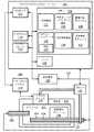
図面において同様の数字は同一若しくは同様の要素をあらわし、最初に図1を参照すると、形状検出可能装置を用いる仮想画像生成のためのシステム100が実施形態例に従って例示される。システム100はワークステーション若しくはコンソール112を含み、ここから手術が監視及び/又は管理される。ワークステーション112は好適にはプログラムとアプリケーションを記憶するためのメモリ116と一つ以上のプロセッサ114を含む。メモリ116は形状検出装置若しくはシステム104からの光学フィードバック信号を解釈するように構成される光学検出モジュール115を記憶し得る。光学検出モジュール115は光学信号フィードバック(及び任意の他のフィードバック、例えば電磁(EM)トラッキング、超音波など)を使用して、医療機器若しくは器具(形状検出可能装置若しくは器具)102及び/又はその周辺領域に関する変形、偏向、及び他の変化を再構成するように構成される。医療機器102(及び/又は102')はカテーテル、ガイドワイヤ、プローブ、内視鏡、ロボット、電極、フィルタ装置、バルーン装置、若しくは他の医療用部品などを含み得る。 In the drawings, like numerals represent the same or similar elements, and first referring to FIG. 1, a system 100 for generating a virtual image using a shape detectable device is illustrated according to an example embodiment. System 100 includes a workstation or console 112 from which operations are monitored and / or managed. Workstation 112 preferably includes
装置102(及び/又は102')上の形状検出システム104は一つ又は複数のセットパターンで装置102に結合される一つ以上の光ファイバ126を含む。光ファイバ126はケーブル127を通じてワークステーション112に接続する。ケーブル127は必要に応じて光ファイバ、電気接続、他の器具などを含み得る。
光ファイバを伴う形状検出システム104は光ファイバブラッググレーティングセンサに基づき得る。光ファイバブラッググレーティング(FBG)は特定波長の光を反射しその他は全て透過する光ファイバの短セグメントである。これはファイバコアに屈折率の周期的変動を加えることによって実現され、これは波長特異的誘電体鏡を生成する。ファイバブラッググレーティングは従って特定波長をブロックするインライン光学フィルタとして、又は波長特異的反射体として使用され得る。
ファイバブラッググレーティングの動作の背景にある基本的原理は、屈折率が変化している界面の各々におけるフレネル反射である。一部の波長では、様々な周期の反射光が同相であるため、反射について強め合う干渉が存在し、その結果、透過について弱め合う干渉が存在する。ブラッグ波長はひずみ及び温度に敏感である。これはブラッググレーティングが光ファイバセンサにおいて検出素子として使用されることができることを意味する。FBGセンサにおいて、測定量(例えばひずみ)はブラッグ波長においてシフトを生じる。 The basic principle behind the operation of fiber Bragg gratings is Fresnel reflection at each of the interfaces where the refractive index is changing. At some wavelengths, reflected light of various periods is in phase, so there is constructive interference for reflection and consequently destructive interference for transmission. Bragg wavelengths are sensitive to strain and temperature. This means that Bragg gratings can be used as sensing elements in fiber optic sensors. In an FBG sensor, the measurand (eg, strain) causes a shift in Bragg wavelength.
この技術の一つの利点は、様々なセンサ素子がファイバの長さにわたって分散され得ることである。構造の中に埋め込まれるファイバの長さに沿って様々なセンサ(ゲージ)を持つ三つ以上のコアを組み込むことは、かかる構造の三次元形状が正確に、典型的には1mm以上の精度で決定されることを可能にする。ファイバの長さに沿って、様々な位置において、多数のFBGセンサが位置付けられ得る(例えば3以上のファイバ検出コア)。各FBGのひずみ測定から、その位置において構造の曲率が推測されることができる。多数の測定位置から、全体の三次元形状が決定される。 One advantage of this technique is that various sensor elements can be distributed over the length of the fiber. Incorporating three or more cores with various sensors (gauges) along the length of the fiber embedded in the structure makes it possible for the three-dimensional shape of such structures to be accurate, typically with an accuracy of 1 mm or more. Allow to be determined. A number of FBG sensors may be located at various locations along the length of the fiber (eg, three or more fiber detection cores). From the strain measurement of each FBG, the curvature of the structure at that location can be inferred. From a number of measurement positions, the overall three-dimensional shape is determined.
光ファイバブラッググレーティングの代替案として、従来の光ファイバにおける固有後方散乱が利用され得る。かかるアプローチの一つは標準単一モード通信ファイバにおいてレイリー散乱を使用することである。レイリー散乱はファイバコア内の屈折率のランダム変動の結果として生じる。これらのランダム変動はグレーティング長に沿って振幅と位相のランダム変動を伴うブラッググレーティングとしてモデル化され得る。単一長のマルチコアファイバ内を走る三つ以上のコアにおいてこの効果を用いることによって、関心面の3D形状とダイナミクスが追跡され得る。 As an alternative to fiber optic Bragg gratings, intrinsic backscatter in conventional fiber optics can be utilized. One such approach is to use Rayleigh scattering in standard single mode communication fiber. Rayleigh scattering results from random fluctuations in the refractive index within the fiber core. These random variations can be modeled as Bragg gratings with random variations in amplitude and phase along the grating length. By using this effect in three or more cores running in a single length multi-core fiber, the 3D shape and dynamics of the surface of interest can be tracked.
光学形状検出(OSS)は外科的介入中の装置の位置確認及びナビゲーションのためにマルチコア光ファイバに沿って光を使用する。関与する原理は固有のレイリー後方散乱若しくは制御されたグレーティングパターンを用いる光ファイバ内のひずみ分布測定を利用する。光ファイバに沿った形状は発射領域156又はz=0として知られるセンサに沿った特定点で開始し、後続の形状位置及び配向はその点に相対的である。カテーテル及びガイドワイヤなどの医療機器に組み込まれる光学形状検出ファイバは、低侵襲手術中の装置のライブガイダンスを提供し、装置102全体の位置と配向を提供し得る。 Optical shape detection (OSS) uses light along a multi-core optical fiber for device localization and navigation during surgical intervention. The principles involved make use of intrinsic Rayleigh backscattering or strain distribution measurements in optical fibers using controlled grating patterns. The shape along the optical fiber starts at a specific point along the launch area 156 or a sensor known as z = 0, and subsequent shape positions and orientations are relative to that point. Optical shape detection fibers incorporated into medical devices, such as catheters and guidewires, can provide live guidance of the device during minimally invasive surgery and provide the position and orientation of the
一実施形態において、ワークステーション112は検出装置104が被検者160内のどこにあるか又はあったかについて、形状検出装置104からのフィードバック(位置データ)を受信するように構成される画像生成モジュール148を含む。画像ボリューム(若しくはデータセット)131は超音波イメージングシステムなどのイメージングシステム110を用いて被検者160内でイメージングされるが、他の術中イメージングシステムが利用されてもよい。データセットの一つ若しくは複数の画像134が、画像ボリューム131をマップアウトするために一つ以上の内部若しくは外部プローブ若しくはトランスデューサ146を用いてイメージングシステム110から収集される。画像134は表示装置118上に表示され得る。画像134は他の術前若しくは術中画像上にオーバーレイされるか、それらと融合されるか、又はそれらと一緒に他の方法で描かれ得る。 In one embodiment, the workstation 112 includes an
ワークステーション112は被検者(患者若しくは他のオブジェクト)160若しくはボリューム131の内部画像を見るためのディスプレイ118を含む。ディスプレイ118はユーザがワークステーション112及びそのコンポーネントと機能若しくはシステム100内の任意の他の素子と相互作用することも可能にし得る。これはインターフェース120によってさらに促進され、これはワークステーション112からのユーザフィードバック及びワークステーション112とのユーザインタラクションを可能にする、キーボード、マウス、ジョイスティック、触覚装置、又は任意の他の周辺機器若しくは制御を含み得る。 The workstation 112 includes a display 118 for viewing an internal image of a subject (patient or other object) 160 or
従来の血管内超音波法(IVUS)は血管系の超音波イメージングを実行するためにカテーテルの遠位端における小型超音波トランスデューサを使用する。IVUSイメージングは血管の横向き(若しくは同心)イメージング又は前向きイメージングのいずれかを実行するために異なる方法でカテーテルに組み込まれ得る。IVUSは血管内皮を視覚化するために通常使用される。これは典型的には所与の血管における血小板の量又は狭窄の程度を決定するために使用される。IVUSの最も一般的な使用は心臓アプリケーション、例えば冠動脈のイメージングである。従来の心腔内心エコー(ICE)カテーテルはリアルタイムの解剖学的イメージングのために心臓に導入され得る。ICEは解剖学的構造、装置の位置を特定するため、及びアブレーション中の高周波エネルギー配給をモニタリングするために電気生理学手術において通常使用される。 Conventional intravascular ultrasound (IVUS) uses a miniature ultrasound transducer at the distal end of a catheter to perform ultrasound imaging of the vasculature. IVUS imaging can be incorporated into catheters in different ways to perform either lateral (or concentric) or forward-looking imaging of blood vessels. IVUS is commonly used to visualize vascular endothelium. This is typically used to determine the amount of platelets or the degree of stenosis in a given blood vessel. The most common use of IVUS is in cardiac applications, such as coronary imaging. Conventional intracardiac echocardiography (ICE) catheters can be introduced into the heart for real-time anatomical imaging. ICE is commonly used in electrophysiology surgery to locate anatomical structures, devices, and to monitor high frequency energy delivery during ablation.
本発明の原理によれば、仮想IVUS及び/又はICE(及び他の手術)が形状検出可能装置102(及び/又は102')と超音波プローブ若しくはトランスデューサ146を用いて実行され得る。超音波プローブ146はコンソール112の一部であり得るか又は別のユニットであり得る超音波イメージングシステム110に結合され得る。装置102の光学形状検出は仮想超音波ボリューム144から仮想超音波画像152を作成するために超音波データセットをリサンプルするために利用される。これは、トランスデューサアパーチャが装置102若しくはカテーテル上にあるか又はそれらに対し既知の変換を持つかのように見えるように、仮想画像152を形成するように超音波画像をリフォーマットするために超音波プローブ146と光学形状検出ファイバ126(カテーテルなどの装置102に、又はその中に結合される)との間の既知の変換(レジストレーションモジュール158に記憶されるか又はメモリ116内のどこかに記憶される変換154)を用いてなされる。仮想画像152は形状検出可能装置102の既知の位置のバンテージポイントから生成される。形状検出可能装置102は仮想画像152を生成するために利用される画像ボリューム144の内側若しくは外側にあり得る。形状検出可能装置102は仮想画像ボリューム(スライス若しくは面)144内に存在しなくてもよいが、画像ボリューム144に対してポジショニングされることができ、画像ボリューム144の外側であってもよい。 In accordance with the principles of the present invention, virtual IVUS and / or ICE (and other operations) may be performed using shape detectable device 102 (and / or 102 ') and ultrasound probe or transducer 146. Ultrasound probe 146 may be coupled to
仮想画像ボリューム144は超音波データセットボリューム131内に生成される。仮想画像ボリューム144は複数の方法で選択若しくは生成され得る。これらは以下の一つ以上を含み得る。仮想画像ボリューム144はプリセット構成(例えば形状とサイズ)を含み得る。形状とサイズはIVUS、ICE又は他の手術若しくはアプリケーションの要件に従って選択され得る。画像152の特性は奥行、視野(FOV)、二次元(2D)、3D、円周、カテーテルに沿った距離などを含みユーザ設定可能であり得、画像ボリューム144は然るべく構成される。仮想画像ボリューム144は形状検出された装置102の形状に基づく自動スライス選択を含み得る。 The
仮想画像ボリューム144は画像中で検出される特徴(心臓アプリケーションの場合、例えば心腔など)に基づく自動ボリューム選択を持ち得る。一実施形態では、ユーザが装置102に沿って様々な位置へドラッグし、装置まわりに回転させ、(例えばマウスをスクロールすることによって)スケールすることなどができるインタラクティブボリュームがディスプレイ118上に表示され得る。仮想画像ボリューム144はボリューム若しくはスライス内で二つ(以上)の装置(102、102')をキャプチャするようにサイズ指定若しくは最適化され得るか、或いは二つの装置では、一方の装置102'がバンテージポイントとなり、他方の装置が仮想画像ボリューム144内で視覚化されるように最適化され得る。装置102及び/又は102'は画像ボリューム144の内側若しくは外側であり得る。 The
一実施形態では、マルチOSS装置102、102'などが利用され得る。装置102、102'は各装置が仮想画像ボリューム144の一部に寄与する複合仮想画像ボリューム144を作成するために利用され得る。装置102'は仮想画像ボリューム144内で視覚化され得る他の装置に対するバンテージポイントとして使用され得る。別の実施形態では、弁若しくはステント留置のためのイメージングが提供され得、ここで形状検出可能装置102は堅いワイヤとして機能し、弁若しくはステントは堅いワイヤを渡って運ばれる。仮想画像ボリューム144は弁を持つOSSワイヤ102から既知のオフセットにおいて選択され得る。この場合、画像ボリューム144内にあるOSS装置102の部分はないが、仮想画像ボリューム144内の仮想スライス、面若しくはボリュームへの既知の変換がわかる。 In one embodiment,
レジストレーションモジュール158はイメージング装置110及び/又はイメージングトランスデューサ若しくはプローブ146の座標系と、形状検出可能装置102若しくは形状検出ファイバ126の座標系とをレジストレーションするように構成される。変換154はこれらの座標系間の座標変換を提供する。変換154は本明細書でより詳細に記載される通り仮想画像152を生成するために画像生成モジュール148によって利用され得る。ロボット142はプローブ若しくはトランスデューサ146と形状検出可能装置102との間で操作とレジストレーションを調整するために利用され得る。 The
図2A‐2Cを参照すると、TEE若しくは外部プローブからの画像を仮想ICE若しくはIVUS画像へ変換する超音波画像リサンプリングの実施例として、元の超音波画像ボリューム202からリサンプルされた、可能な仮想イメージングボリューム204、206及び208が示される。イメージングボリューム204、206及び208はICEのような横向き画像ボリューム(図2A)、IVUSのような円周画像(図2B)、若しくは前向き画像ボリューム(図2C)を含み得る。前向き画像(図2C)は腔内ビューを与えるために使用され得、器具102とイメージングされている解剖学的構造の超音波画像両方の"一人称"視点を与えるために装置102のまさに先端から後退されていてもよい。上記画像ボリュームの代わりに若しくは加えて画像面若しくはスライス(二次元)画像も利用され得ることが理解されるべきである。 Referring to FIGS. 2A-2C, an example of ultrasound image resampling to convert an image from a TEE or external probe to a virtual ICE or IVUS image is a possible virtual image resampled from the original
一実施形態において、光学形状検出カテーテル102は、仮想アパーチャと画像視野が超音波データセット(例えばボリューム202)内にとどまる限り、仮想超音波アパーチャがカテーテル102に沿って平行移動されカテーテル102まわりに回転されることを許可する。 In one embodiment, the optical
図3を参照すると、別のUSボリューム202が形状検出可能カテーテル102を含み、これは仮想画像ボリューム216の第1の位置210から矢印214の方向に画像ボリューム216の第2の位置212へ動かされる。図3は仮想IVUSプルバックを示し、オペレータは仮想アパーチャをカテーテル102若しくは他の装置に沿ってスライドすることができる。 Referring to FIG. 3, another
超音波画像は単一トランスデューサ、例えば経食道心エコー検査(TEE)トランスデューサ、鼻TEEプローブ、若しくは外面プローブ(C5‐2プローブなど)から生成され得る。さらに、より大きな領域にわたってカテーテル102をトラックするためにマルチトランスデューサも利用され得る。これらの実施形態は図4‐6を参照して示される。マルチトランスデューサ/ソースはOSSファイバの位置を用いてどのプローブをイメージングソースとして使用するかを選択するために利用され得る。さらに、各トランスデューサの視野間の画像を縫い合わせるためにマルチソースが利用され得る。OSSファイバの位置は関心領域(装置の場所)における画像合成を向上させるために超音波プローブのビームステアリングにも使用され得る。 Ultrasound images may be generated from a single transducer, for example, a transesophageal echocardiography (TEE) transducer, a nasal TEE probe, or an external probe (such as a C5-2 probe). Further, multi-transducers may be utilized to track the
図4を参照すると、断面図はTEEプローブ306上にTEEトランスデューサ304を持つ患者302を示す。トランスデューサ304は患者302の食道を通過され、患者302内の超音波イメージングボリューム308を作り出す。イメージングボリューム308は、形状検出可能装置314(例えばカテーテル)が中に光学形状検出ファイバ312を持つ一つ若しくは複数の領域と重なる。装置314は患者における自然開口を通して若しくはポートを通して設けられ得る。仮想画像ボリューム310(例えば仮想ICE若しくは仮想IVUS装置)はイメージングボリューム308のデータセットの少なくとも一部を用いて得られる。仮想画像ボリューム310は装置314に沿った及びイメージングボリューム308内の選択された場所と配向においてアンカーされる。仮想画像ボリューム310の仮想画像は形状検出可能装置314上のバンテージポイントから提供され得る。 Referring to FIG. 4, a cross-sectional view shows a
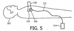
図5を参照すると、断面図は患者302内の超音波イメージングボリューム308を生成するための単一外部トランスデューサ320(プローブ)とともに患者302を示す。イメージングボリューム308は形状検出可能装置314(例えばカテーテル)が中に光学形状検出ファイバ312を持つ一つ若しくは複数の領域と重なる。仮想画像ボリューム310(例えば仮想ICE若しくは仮想IVUS装置)はイメージングボリューム308のデータセットの少なくとも一部を用いて得られる。仮想画像ボリューム310は装置314に沿った及びイメージングボリューム308内の選択された場所と配向においてアンカーされる。 Referring to FIG. 5, a cross-sectional view shows the
図6を参照すると、断面図は患者302内の超音波イメージングボリューム308に対するマルチ超音波アパーチャ(ウィンドウ)318を生成するための複数の外部トランスデューサ322とともに患者302を示す。イメージングボリューム308は形状検出可能装置314(例えばカテーテル)が中に光学形状検出ファイバ312を持つ一つ若しくは複数の領域と重なる複合ウィンドウ308の領域を含む。仮想画像ボリューム310(例えば仮想ICE若しくは仮想IVUS装置)はイメージングボリューム308のデータセットの少なくとも一部を用いて得られる。仮想画像ボリューム310は装置314に沿った及びイメージングボリューム308内の選択された場所と配向においてアンカーされる。 Referring to FIG. 6, a cross-sectional view shows a
仮想画像ボリューム310を得るために超音波画像をリサンプルするには、画像ボリューム308に対する超音波トランスデューサアパーチャと仮想画像ボリューム310に対する仮想アパーチャとの間の変換を知る必要がある。特に有用な実施形態において、この変換を得るために以下の方法が利用され得る。一実施形態において、形状検出されたトランスデューサ(内部若しくは外部)と形状検出されたカテーテルが提供され得る。この場合、二つの形状検出座標系をレジストレーションする一つの方法は、手術の前に、二つの形状検出された装置の発射器具が、点に基づくレジストレーション若しくは形状に基づくレジストレーションを用いて一緒にレジストレーションされるものである。 To resample an ultrasound image to obtain a
別の実施形態において、蛍光透視法に基づくレジストレーションが実行され得る。例えば、TEEプローブヘッドがx線画像にレジストレーションされ得(例えばEchoNav(登録商標)のように)、OSSカテーテルが同様にx線画像にレジストレーションされ得、TEEプローブヘッドとOSS装置との間の変換を提供する。TEEプローブヘッドはx線を介して動的にトラックされる必要があり得るが、OSS装置は一度x線画像にレジストレーションされれば十分である。さらに別の実施形態において、代替的にトラックされたトランスデューサと形状検出されたカテーテルが利用され得る。トランスデューサヘッドは他のトラッキング技術(例えば外部トランスデューサの場合電磁トラッキング若しくは光学トラッキング)を用いてトラックされ得、光学形状検出装置の発射器具はその代替トラッキング法にレジストレーションされ得る。他のレジストレーション技術及び方法も可能であり、本発明の原理に従って検討される。 In another embodiment, fluoroscopy-based registration may be performed. For example, a TEE probe head can be registered to an x-ray image (eg, like EchoNav®), an OSS catheter can be similarly registered to an x-ray image, and the Provides conversion. Although the TEE probe head may need to be dynamically tracked via x-rays, it is sufficient for the OSS device to be registered once to the x-ray image. In yet another embodiment, alternatively a tracked transducer and a shape-detected catheter may be utilized. The transducer head can be tracked using other tracking techniques (eg, electromagnetic or optical tracking in the case of an external transducer), and the launch instrument of the optical shape detection device can be registered to that alternative tracking method. Other registration techniques and methods are possible and are contemplated according to the principles of the present invention.
上記実施形態は仮想ICE/IVUSカテーテルのロボット制御された超音波トラッキングを含み得る。仮想ICE/IVUSカテーテルは、仮想画像が超音波視野内にあるときに機能する。従って、超音波オペレータはカテーテルの正確な部分が視野内にあるように超音波プローブを位置付ける必要がある。臨床ワークフローへの影響を減らすために、超音波プローブ(304、320、322)は超音波データセット内にカテーテル位置を維持するようにロボット制御され得る。超音波トランスデューサヘッドと表面(画像処理若しくはマニュアル観察を介して検出される)との間の結合若しくは圧力の欠如に起因して超音波品質が低下するか若しくは失われる場合、ロボットはこれを検出して補正し(例えば面への圧力を増すこと若しくは面にゲルを放出することによって)、そしてイメージングの実行を続けることができる。ロボット制御は同時に超音波データセット308内に仮想イメージングボリューム310を維持することができ、トランスデューサ304、320若しくは322の物理的位置を仮想画像解像度について最適化することができ、患者302にかかる力を最小化しながら、イメージングのために組織と適切な接触を維持するように臨床アプリケーションの物理的制約の範囲内で作用することができる。ロボット制御されるTEEプローブ306の場合、ロボットの制御は曲面プローブ先端の位置を変える二つのダイヤルの制御を含み得る。 The above embodiments may include robotic controlled ultrasound tracking of a virtual ICE / IVUS catheter. Virtual ICE / IVUS catheters function when the virtual image is within the ultrasound field of view. Therefore, the ultrasound operator needs to position the ultrasound probe so that the correct portion of the catheter is within the field of view. To reduce the impact on clinical workflow, the ultrasound probe (304, 320, 322) may be robotically controlled to maintain the catheter position within the ultrasound dataset. If the ultrasonic quality is reduced or lost due to a lack of coupling or pressure between the ultrasonic transducer head and the surface (detected via image processing or manual observation), the robot will detect this. (For example, by increasing the pressure on the surface or releasing the gel on the surface) and continuing to perform the imaging. Robot control can simultaneously maintain the
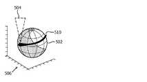
図7Aと7Bを参照すると、ダイヤル(不図示)で制御されるときのTEEプローブ先端の可動域を示す実験結果が示される。TEEプローブのハンドル上のダイヤルを制御するシステムは操縦可能なプローブ先端の位置をロボット制御する。ロボット制御されるTEEプローブの場合、ロボットの制御(142、図1)は曲面プローブ先端510の位置を変更するための二つのダイヤルの制御を含み得る。 Referring to FIGS. 7A and 7B, experimental results showing the range of motion of the TEE probe tip when controlled by a dial (not shown) are shown. A system for controlling the dial on the handle of the TEE probe robotically controls the position of the steerable probe tip. In the case of a robot-controlled TEE probe, controlling the robot (142, FIG. 1) may include controlling two dials to change the position of the
TEEプローブによって可能な可動域、及び開始画像(図7A)からターゲット画像(図7B)へ動くために必要な動きの図が示される。球502上の全ての点は対応する画像ボリューム504を伴うプローブヘッド510の固有配向を持つことになる。球502の点とこれらの点に関連するボリューム配向はプローブ510に特有であり、ロボット制御系においてルックアップテーブル若しくは変換に保存され得る。ターゲット514がロボットの座標フレーム506において選択されると、ターゲット514がボリューム504の中央になるように超音波(US)ボリュームの理想配向512が計算される。この配向512は、プローブ510の位置にマッチされるルックアップテーブル中の最も近い配向にマッチされる。ロボットは組織への力を制限しながら制御ダイヤルを制御することによってその位置に達しようと試みる。動きにおいて過度の力が加えられない場合ロボットはターゲット504を見るために最適な位置に達することになる。力の限界に達する場合、イメージング装置の視点は準最適となるが、制約を踏まえると最適化される。 An illustration of the range of motion possible with the TEE probe and the movement required to move from the starting image (FIG. 7A) to the target image (FIG. 7B) is shown. Every point on the
イメージング装置のロボット制御は超音波プローブの制御にとって多数の実施例を持ち得る。例えば、TEEプローブのハンドル上のダイヤルを制御し、操縦可能なプローブ先端の位置をロボット制御するシステムだけでなく、他のロボットシステムと方法も利用され得る。 Robotic control of the imaging device can have many embodiments for control of the ultrasound probe. For example, other robotic systems and methods may be utilized, as well as systems that control the dial on the handle of the TEE probe and robotically control the position of the steerable probe tip.
図8を参照すると、カテーテルの正確な面における仮想ビューの適切な生成を可能にするために、USプローブ510がカテーテル516の近位端の形状からガイドされるように制御スキームが修正され得る。この実施形態において、カテーテル516の形状は面518にフィットされる。プローブ作業空間中の点に対する面518の配向は、仮想画像面520と物理的画像面518の間の角度が最小化され、仮想画像ボリューム520のサイズが最大化されるように最適化される。 Referring to FIG. 8, the control scheme may be modified such that the
さらなる実施形態において、ロボットは仮想超音波ボリュームを生成するために最適位置へ移動し、そして何らかの他の特徴(例えば別の装置若しくは弁)を視覚化するために元の位置に戻ることができる。最適面はプローブヘッド510の最適位置を決定するために装置516の遠位部を通して決定され得る。この動きはロボットエンコーダとロボット作業空間からわかるので、物理的(518)及び仮想(520)ボリューム間の関係もわかり、同じ基準フレームにおいて視覚化されることができる。新たなプローブ位置において見える仮想ボリュームの部分は物理的ボリュームからアップデートされ、"オフライン"ボリューム視覚化の背景で示され得る。ロボットはボリューム全体をアップデートするために二つの異なる位置間で動かされることができる。 In further embodiments, the robot can move to an optimal position to generate a virtual ultrasound volume and return to its original position to visualize some other feature (eg, another device or valve). The optimal plane may be determined through the distal portion of the
仮想ICE/IVUS画像は元の超音波画像と同じ配向で整列されない可能性がある。結果として、リサンプル画像の解像度は準最適になり得る。超音波収集の最適化は以下の項目の一つ以上によって対処され得る。最高解像度サンプリングが仮想画像と同一面内で同一方向になるように超音波トランスデューサの位置が物理的に調節され得る。これはオペレータへ視覚フィードバックを与えることによって、又は上記の通りロボット制御を利用することによってなされ得る。別の方法は最高解像度方向が仮想ICE若しくは仮想IVUS画像と同一面内になるようにトランスデューサ送信プロファイルを適応させること、又はビーム形成スキーム若しくは複合スキームを用いることを含む。より良い解像度は、フレームレートが増大され得るか若しくはマルチビーム角度が使用され得るように必要な3D超音波ボリュームのみへ視野を削減することによっても実現されることができる。解像度を最適化するために上記方法の組み合わせも利用され得る。 The virtual ICE / IVUS image may not be aligned with the same orientation as the original ultrasound image. As a result, the resolution of the resampled image can be suboptimal. Optimization of ultrasound acquisition may be addressed by one or more of the following items. The position of the ultrasound transducer may be physically adjusted such that the highest resolution sampling is in the same direction and in the same plane as the virtual image. This can be done by providing visual feedback to the operator or by utilizing robotic controls as described above. Other methods include adapting the transducer transmission profile so that the highest resolution direction is in the same plane as the virtual ICE or virtual IVUS image, or using a beamforming or compounding scheme. Better resolution can also be achieved by reducing the field of view to only the required 3D ultrasound volume so that the frame rate can be increased or multiple beam angles can be used. Combinations of the above methods can also be used to optimize resolution.
図9を参照すると、本発明の原理にかかる仮想イメージングのための方法が例示的に描かれる。ブロック602において、被検者の領域が術中イメージングシステムでイメージングされ、その領域に対する画像データセットを生成する。ブロック606において、形状検出可能装置の少なくとも一部が、領域内若しくは領域の外側のバンテージポイントとしてポジショニングされる。一つ若しくは複数の形状検出可能装置は光ファイバを含んでもよく、術中イメージングシステムは超音波イメージングシステムを含み得る。超音波イメージングシステムはイメージングされる被検者内に内部に若しくは外部に留置される一つ以上の超音波トランスデューサを含み得る。 Referring to FIG. 9, a method for virtual imaging according to the principles of the present invention is illustratively depicted. At
ブロック610において、形状検出可能装置の座標系が術中イメージングシステムの座標系とレジストレーションされる。レジストレーションは:形状に基づく(例えば形状対形状)レジストレーション、画像に基づくレジストレーション、及びトラッキング法レジストレーションのうち少なくとも一つを含み得る。他のレジストレーション技術も利用され得る。 At
ブロック614において、画像データセットを用いて領域の少なくとも一部の仮想画像が生成され、仮想画像は形状検出可能装置の位置からのバンテージポイントを含む。ブロック618において、仮想画像は:横向き画像、円周画像、及び前向き画像のうち少なくとも一つを含む形状を持つ、仮想画像ボリューム、面若しくはスライスを含み得る。他の幾何学的形状も仮想画像ボリュームに与えられ得る。これらはユーザ設定され、プリセットされる、スライスなどであり得る。 At
ブロック620において、仮想画像は画像データセット(若しくは領域)を仮想画像へ変換するように構成される一つ若しくは複数の変換を利用することによって生成され得る。ブロック622において、ロボットを用いて術中イメージングシステムと形状検出可能装置の間で操作が調整され得る。例えば、ロボットはシステム間の調整を確保するためにUSトランスデューサをカテーテル若しくは他の装置に対して動かし得る。ロボットはイメージングトランスデューサを、これがOSS装置に従い、必要な若しくは望ましい仮想画像を維持するようにポジショニングする。 At
添付の請求項を解釈するに当たり、以下のことが理解されるべきである:
a)"有する"という語は所与の請求項に列挙されるもの以外の要素若しくは動作の存在を除外しない。
b)ある要素に先行する"a"若しくは"an"という語はかかる要素の複数の存在を除外しない。
c)請求項における任意の参照符号はその範囲を限定しない。
d)複数の"手段"は、同じ項目又はハードウェア若しくはソフトウェア実施構造若しくは機能によってあらわされ得る。
e)特に指定されない限り特定の動作順序が要求されることを意図しない。In interpreting the appended claims, it should be understood that:
a) the word "comprising" does not exclude the presence of elements or acts other than those listed in a given claim;
b) the word "a" or "an" preceding an element does not exclude the presence of a plurality of such elements.
c) any reference signs in the claims do not limit their scope;
d) Multiple "means" may be represented by the same item or hardware or software implementation structure or function.
e) Unless otherwise specified, no particular order of operation is required.
光学形状検出装置の視点を伴う仮想画像について好適な実施形態を記載したが(これらは例示であって限定ではないことが意図される)、上記教示に照らして修正及び変更が当業者によってなされ得ることが留意される。従って添付の請求項によって概説される通り本明細書に開示の実施形態の範囲内にある変更が開示の実施形態の特定の実施形態においてなされ得ることが理解されるものとする。特許法によって要求される特徴と詳細をこのように記載したが、特許証による保護を望まれる特許請求の範囲は添付の請求項に定義される。 Although the preferred embodiments have been described for virtual images with the viewpoint of an optical shape detection device (these are intended to be illustrative and not limiting), modifications and changes may be made by those skilled in the art in light of the above teachings. It is noted that It is, therefore, to be understood that modifications that fall within the scope of the embodiments disclosed herein, as outlined by the appended claims, may be made in specific embodiments of the disclosed embodiments. Having thus described the features and details required by the Patent Act, the scope of the claims for which protection is sought is defined by the appended claims.
Claims (20)
Translated fromJapanese領域に対する画像データセットを生成するように構成されるトランスデューサを持つ術中イメージングシステムと、
形状検出可能装置であって、当該形状検出可能装置の少なくとも一部を前記領域に対してポジショニングするように構成され、前記術中イメージングシステムの座標系とレジストレーションされる座標系を持つ、形状検出可能装置と、
前記画像データを用いて前記領域の少なくとも一部の仮想画像をレンダリングするように構成される画像生成モジュールであって、当該仮想画像は前記形状検出可能装置上の位置に対するバンテージポイントを含む、画像生成モジュールと
を有する、システム。A system for giving a viewpoint to a virtual image,
An intraoperative imaging system having a transducer configured to generate an image data set for the region;
A shape detectable device configured to position at least a portion of the shape detectable device with respect to the region, the shape detectable device having a coordinate system registered with a coordinate system of the intraoperative imaging system. Equipment and
An image generation module configured to render a virtual image of at least a portion of the region using the image data, the virtual image including a vantage point relative to a location on the shape detectable device. A system comprising: a module;
領域に対する画像データセットを生成するように構成されるトランスデューサを持つ術中イメージングシステムと、
形状検出可能装置であって、当該形状検出可能装置の少なくとも一部を前記領域に対してポジショニングするように構成され、前記術中イメージングシステムの座標系とレジストレーションされる座標系を持つ、形状検出可能装置と、
前記画像データセットを用いて前記領域の少なくとも一部の仮想画像をレンダリングするように構成される画像生成モジュールであって、当該仮想画像は前記形状検出可能装置上の位置に対するバンテージポイントを含む、画像生成モジュールと、
ロボットが術中に前記形状検出可能装置に対して画像を維持するように、前記術中イメージングシステムと前記形状検出可能装置の間で動作を調整するように構成されるロボットと
を有する、システム。A system for giving a viewpoint to a virtual image,
An intraoperative imaging system having a transducer configured to generate an image data set for the region;
A shape detectable device configured to position at least a portion of the shape detectable device with respect to the region, the shape detectable device having a coordinate system registered with a coordinate system of the intraoperative imaging system. Equipment and
An image generation module configured to render a virtual image of at least a portion of the region using the image dataset, the virtual image including a vantage point relative to a location on the shape-detectable device. A generation module;
A system comprising: an intraoperative imaging system and a robot configured to coordinate movement between the intraoperative imaging system and the shape detectable device such that the robot maintains images against the shape detectable device during surgery.
術中イメージングシステムで対象の領域をイメージングして、前記領域に対する画像データセットを生成するステップと、
前記領域に対して形状検出可能装置の少なくとも一部をポジショニングするステップと、
前記形状検出可能装置の座標系を前記術中イメージングシステムの座標系とレジストレーションするステップと、
前記画像データセットを用いて前記領域の少なくとも一部の仮想画像を生成するステップであって、当該仮想画像は前記形状検出可能装置上の位置からのバンテージポイントを含む、ステップと
を有する、方法。A method for virtual imaging, comprising:
Imaging a region of interest with an intraoperative imaging system to generate an image dataset for the region;
Positioning at least a portion of the shape detectable device with respect to the region,
Registering the coordinate system of the shape detectable device with the coordinate system of the intraoperative imaging system,
Generating a virtual image of at least a portion of the region using the image dataset, the virtual image including a vantage point from a location on the shape detectable device.
Applications Claiming Priority (2)
| Application Number | Priority Date | Filing Date | Title |
|---|---|---|---|
| US201461930974P | 2014-01-24 | 2014-01-24 | |
| US61/930,974 | 2014-01-24 |
Related Parent Applications (1)
| Application Number | Title | Priority Date | Filing Date |
|---|---|---|---|
| JP2016547083ADivisionJP2017503593A (en) | 2014-01-24 | 2015-01-04 | Virtual image with viewpoint of optical shape detection device |
Publications (3)
| Publication Number | Publication Date |
|---|---|
| JP2020028718Atrue JP2020028718A (en) | 2020-02-27 |
| JP7050733B2 JP7050733B2 (en) | 2022-04-08 |
| JP7050733B6 JP7050733B6 (en) | 2022-06-01 |
Family
ID=52462966
Family Applications (2)
| Application Number | Title | Priority Date | Filing Date |
|---|---|---|---|
| JP2016547083APendingJP2017503593A (en) | 2014-01-24 | 2015-01-04 | Virtual image with viewpoint of optical shape detection device |
| JP2019178921AActiveJP7050733B6 (en) | 2014-01-24 | 2019-09-30 | Virtual image with viewpoint of optical shape detector |
Family Applications Before (1)
| Application Number | Title | Priority Date | Filing Date |
|---|---|---|---|
| JP2016547083APendingJP2017503593A (en) | 2014-01-24 | 2015-01-04 | Virtual image with viewpoint of optical shape detection device |
Country Status (5)
| Country | Link |
|---|---|
| US (1) | US11617623B2 (en) |
| EP (1) | EP3096692B1 (en) |
| JP (2) | JP2017503593A (en) |
| CN (1) | CN105979879B (en) |
| WO (1) | WO2015110928A1 (en) |
Cited By (1)
| Publication number | Priority date | Publication date | Assignee | Title |
|---|---|---|---|---|
| US11399801B2 (en)* | 2017-11-24 | 2022-08-02 | Canon Medical Systems Corporation | Medical diagnostic-imaging apparatus and medical-image processing apparatus |
Families Citing this family (59)
| Publication number | Priority date | Publication date | Assignee | Title |
|---|---|---|---|---|
| US8672837B2 (en) | 2010-06-24 | 2014-03-18 | Hansen Medical, Inc. | Methods and devices for controlling a shapeable medical device |
| AU2011272764B2 (en)* | 2010-06-30 | 2015-11-19 | Muffin Incorporated | Percutaneous, ultrasound-guided introduction of medical devices |
| US10238837B2 (en) | 2011-10-14 | 2019-03-26 | Intuitive Surgical Operations, Inc. | Catheters with control modes for interchangeable probes |
| US20130303944A1 (en) | 2012-05-14 | 2013-11-14 | Intuitive Surgical Operations, Inc. | Off-axis electromagnetic sensor |
| US9387048B2 (en) | 2011-10-14 | 2016-07-12 | Intuitive Surgical Operations, Inc. | Catheter sensor systems |
| US9452276B2 (en) | 2011-10-14 | 2016-09-27 | Intuitive Surgical Operations, Inc. | Catheter with removable vision probe |
| US20140148673A1 (en) | 2012-11-28 | 2014-05-29 | Hansen Medical, Inc. | Method of anchoring pullwire directly articulatable region in catheter |
| US9057600B2 (en) | 2013-03-13 | 2015-06-16 | Hansen Medical, Inc. | Reducing incremental measurement sensor error |
| US9271663B2 (en) | 2013-03-15 | 2016-03-01 | Hansen Medical, Inc. | Flexible instrument localization from both remote and elongation sensors |
| US9014851B2 (en) | 2013-03-15 | 2015-04-21 | Hansen Medical, Inc. | Systems and methods for tracking robotically controlled medical instruments |
| US9629595B2 (en) | 2013-03-15 | 2017-04-25 | Hansen Medical, Inc. | Systems and methods for localizing, tracking and/or controlling medical instruments |
| US11020016B2 (en) | 2013-05-30 | 2021-06-01 | Auris Health, Inc. | System and method for displaying anatomy and devices on a movable display |
| EP3243476B1 (en) | 2014-03-24 | 2019-11-06 | Auris Health, Inc. | Systems and devices for catheter driving instinctiveness |
| EP3200718A4 (en) | 2014-09-30 | 2018-04-25 | Auris Surgical Robotics, Inc | Configurable robotic surgical system with virtual rail and flexible endoscope |
| US10314463B2 (en) | 2014-10-24 | 2019-06-11 | Auris Health, Inc. | Automated endoscope calibration |
| JP6824967B2 (en) | 2015-09-18 | 2021-02-03 | オーリス ヘルス インコーポレイテッド | Tubular net navigation |
| WO2017051279A1 (en)* | 2015-09-24 | 2017-03-30 | Koninklijke Philips N.V. | System and method to find improved views in transcatheter valve replacement with combined optical shape sensing and ultrasound image guidance |
| US11253168B2 (en)* | 2015-11-26 | 2022-02-22 | Koninklijke Philips N.V. | Methods and systems for visualizing shapes of tracked devices |
| US10143526B2 (en) | 2015-11-30 | 2018-12-04 | Auris Health, Inc. | Robot-assisted driving systems and methods |
| CN108472082B (en) | 2015-12-29 | 2021-08-10 | 皇家飞利浦有限公司 | Registration system for medical navigation and method of operation thereof |
| US9931025B1 (en)* | 2016-09-30 | 2018-04-03 | Auris Surgical Robotics, Inc. | Automated calibration of endoscopes with pull wires |
| EP3558151B1 (en)* | 2016-12-20 | 2023-07-05 | Koninklijke Philips N.V. | Navigation platform for an intracardiac catheter |
| US10244926B2 (en) | 2016-12-28 | 2019-04-02 | Auris Health, Inc. | Detecting endolumenal buckling of flexible instruments |
| WO2018183727A1 (en) | 2017-03-31 | 2018-10-04 | Auris Health, Inc. | Robotic systems for navigation of luminal networks that compensate for physiological noise |
| KR102643758B1 (en) | 2017-05-12 | 2024-03-08 | 아우리스 헬스, 인코포레이티드 | Biopsy devices and systems |
| US10022192B1 (en) | 2017-06-23 | 2018-07-17 | Auris Health, Inc. | Automatically-initialized robotic systems for navigation of luminal networks |
| US10299870B2 (en) | 2017-06-28 | 2019-05-28 | Auris Health, Inc. | Instrument insertion compensation |
| US10426559B2 (en) | 2017-06-30 | 2019-10-01 | Auris Health, Inc. | Systems and methods for medical instrument compression compensation |
| US10145747B1 (en) | 2017-10-10 | 2018-12-04 | Auris Health, Inc. | Detection of undesirable forces on a surgical robotic arm |
| US10555778B2 (en) | 2017-10-13 | 2020-02-11 | Auris Health, Inc. | Image-based branch detection and mapping for navigation |
| US11058493B2 (en) | 2017-10-13 | 2021-07-13 | Auris Health, Inc. | Robotic system configured for navigation path tracing |
| EP3684282B1 (en) | 2017-12-06 | 2024-02-21 | Auris Health, Inc. | Systems to correct for uncommanded instrument roll |
| US11510736B2 (en) | 2017-12-14 | 2022-11-29 | Auris Health, Inc. | System and method for estimating instrument location |
| WO2019125964A1 (en) | 2017-12-18 | 2019-06-27 | Auris Health, Inc. | Methods and systems for instrument tracking and navigation within luminal networks |
| US11771399B2 (en) | 2018-02-07 | 2023-10-03 | Atherosys, Inc. | Apparatus and method to guide ultrasound acquisition of the peripheral arteries in the transverse plane |
| KR20240118200A (en) | 2018-02-13 | 2024-08-02 | 아우리스 헬스, 인코포레이티드 | System and method for driving medical instrument |
| WO2019175129A1 (en)* | 2018-03-12 | 2019-09-19 | Koninklijke Philips N.V. | Ultrasound imaging plane alignment using neural networks and associated devices, systems, and methods |
| JP7225259B2 (en) | 2018-03-28 | 2023-02-20 | オーリス ヘルス インコーポレイテッド | Systems and methods for indicating probable location of instruments |
| WO2019191144A1 (en) | 2018-03-28 | 2019-10-03 | Auris Health, Inc. | Systems and methods for registration of location sensors |
| EP3787480A4 (en) | 2018-04-30 | 2022-01-26 | Atherosys, Inc. | METHOD AND DEVICE FOR AUTOMATIC DETECTION OF ATHEROMEA IN PERIPHERAL ARTERIES |
| US10905499B2 (en) | 2018-05-30 | 2021-02-02 | Auris Health, Inc. | Systems and methods for location sensor-based branch prediction |
| JP7371026B2 (en) | 2018-05-31 | 2023-10-30 | オーリス ヘルス インコーポレイテッド | Path-based navigation of tubular networks |
| MX2020012904A (en) | 2018-05-31 | 2021-02-26 | Auris Health Inc | Image-based airway analysis and mapping. |
| KR102567087B1 (en)* | 2018-05-31 | 2023-08-17 | 아우리스 헬스, 인코포레이티드 | Robotic systems and methods for navigation of luminal networks detecting physiological noise |
| KR102852843B1 (en) | 2018-09-28 | 2025-09-03 | 아우리스 헬스, 인코포레이티드 | System and method for docking medical devices |
| CN112804959B (en) | 2018-09-28 | 2025-01-28 | 奥瑞斯健康公司 | Robotic systems and methods for accompanying endoscopic and percutaneous medical procedures |
| US11596382B2 (en)* | 2019-02-18 | 2023-03-07 | Bfly Operations, Inc. | Methods and apparatuses for enabling a user to manually modify an input to a calculation performed based on an ultrasound image |
| US11346941B2 (en)* | 2019-03-26 | 2022-05-31 | Texas Instruments Incorporated | Shaped ultrasonic transmission and echo processing with coding |
| US11207141B2 (en) | 2019-08-30 | 2021-12-28 | Auris Health, Inc. | Systems and methods for weight-based registration of location sensors |
| US11147633B2 (en) | 2019-08-30 | 2021-10-19 | Auris Health, Inc. | Instrument image reliability systems and methods |
| WO2021137108A1 (en) | 2019-12-31 | 2021-07-08 | Auris Health, Inc. | Alignment interfaces for percutaneous access |
| EP4084721B1 (en) | 2019-12-31 | 2025-10-01 | Auris Health, Inc. | Anatomical feature identification and targeting |
| WO2021137109A1 (en) | 2019-12-31 | 2021-07-08 | Auris Health, Inc. | Alignment techniques for percutaneous access |
| EP4091129A1 (en)* | 2020-01-14 | 2022-11-23 | Koninklijke Philips N.V. | Image enhancement based on fiber optic shape sensing |
| WO2021161515A1 (en)* | 2020-02-14 | 2021-08-19 | 朝日インテック株式会社 | System and method for detecting position of long medical device |
| WO2021186330A1 (en)* | 2020-03-16 | 2021-09-23 | St. Jude Medical International Holding S.À.R.L. | System and method for optical sensor reference frame alignment |
| US11737663B2 (en) | 2020-03-30 | 2023-08-29 | Auris Health, Inc. | Target anatomical feature localization |
| CN115969409A (en)* | 2021-10-14 | 2023-04-18 | 巴德阿克塞斯系统股份有限公司 | Optical fiber ultrasonic probe |
| US20230190233A1 (en)* | 2021-12-20 | 2023-06-22 | Biosense Webster (Israel) Ltd. | Visualization of change in anatomical slope using 4d ultrasound catheter |
Citations (4)
| Publication number | Priority date | Publication date | Assignee | Title |
|---|---|---|---|---|
| JP2001037756A (en)* | 1999-07-30 | 2001-02-13 | Toshiba Corp | Ultrasound diagnostic equipment |
| US20040097805A1 (en)* | 2002-11-19 | 2004-05-20 | Laurent Verard | Navigation system for cardiac therapies |
| JP2011156286A (en)* | 2010-02-03 | 2011-08-18 | Toshiba Corp | Ultrasonic diagnosis apparatus and ultrasonic image displaying program |
| JP2012254279A (en)* | 2011-05-13 | 2012-12-27 | Sony Corp | Image processing device, image processing method, program, recording medium, image processing system, and probe |
Family Cites Families (27)
| Publication number | Priority date | Publication date | Assignee | Title |
|---|---|---|---|---|
| EP0999785A4 (en)* | 1997-06-27 | 2007-04-25 | Univ Leland Stanford Junior | METHOD AND APPARATUS FOR GENERATING THREE-DIMENSIONAL IMAGES FOR "NAVIGATION" PURPOSES |
| DE10025285A1 (en)* | 2000-05-22 | 2001-12-06 | Siemens Ag | Fully automatic, robot-assisted camera guidance using position sensors for laparoscopic interventions |
| JP2002119507A (en) | 2000-10-17 | 2002-04-23 | Toshiba Corp | Medical device and medical image collection and display method |
| JP3805231B2 (en)* | 2001-10-26 | 2006-08-02 | キヤノン株式会社 | Image display apparatus and method, and storage medium |
| JP3711335B2 (en)* | 2001-12-04 | 2005-11-02 | アロカ株式会社 | Ultrasonic image processing apparatus and ultrasonic echo signal processing apparatus |
| US20040106869A1 (en) | 2002-11-29 | 2004-06-03 | Ron-Tech Medical Ltd. | Ultrasound tracking device, system and method for intrabody guiding procedures |
| JP4546042B2 (en)* | 2003-05-16 | 2010-09-15 | オリンパス株式会社 | Virtual image display device |
| US20050033117A1 (en)* | 2003-06-02 | 2005-02-10 | Olympus Corporation | Object observation system and method of controlling object observation system |
| DE10334074A1 (en)* | 2003-07-25 | 2005-02-24 | Siemens Ag | Medical 3-D image virtual channel viewing unit processes preoperative tomography data to show virtual channel linked to instrument position |
| JP4999012B2 (en)* | 2005-06-06 | 2012-08-15 | インチュイティブ サージカル,インコーポレイテッド | Laparoscopic ultrasonic robotic surgical system |
| WO2007047782A2 (en) | 2005-10-20 | 2007-04-26 | Intuitive Surgical, Inc | Auxiliary image display and manipulation on a computer display in a medical robotic system |
| US8267927B2 (en) | 2007-01-24 | 2012-09-18 | Koninklijke Philips Electronics N.V. | Advanced ablation planning |
| CN100468465C (en)* | 2007-07-13 | 2009-03-11 | 中国科学技术大学 | Stereo vision 3D face modeling method based on virtual image correspondence |
| EP2240111B1 (en)* | 2008-06-18 | 2019-07-24 | Mako Surgical Corp. | Fiber optic tracking system |
| CN102598088A (en)* | 2009-11-11 | 2012-07-18 | 艾克提维尤斯有限公司 | Systems & methods for planning and performing percutaneous needle procedures |
| RU2589625C2 (en)* | 2010-02-09 | 2016-07-10 | Конинклейке Филипс Электроникс Н.В. | Device, system and method for imaging and treatment using optical determination of position |
| CN102858229B (en)* | 2010-02-18 | 2015-11-25 | 皇家飞利浦电子股份有限公司 | Systems and methods for tumor motion simulation and motion compensation using tracked bronchoscopy |
| DE102010051206A1 (en)* | 2010-11-12 | 2012-05-16 | Valeo Schalter Und Sensoren Gmbh | A method of generating an image of a vehicle environment and imaging device |
| JP6195822B2 (en)* | 2011-03-31 | 2017-09-13 | コーニンクレッカ フィリップス エヌ ヴェKoninklijke Philips N.V. | Shape detection to support medical procedures |
| US10376179B2 (en) | 2011-04-21 | 2019-08-13 | Koninklijke Philips N.V. | MPR slice selection for visualization of catheter in three-dimensional ultrasound |
| US8900131B2 (en)* | 2011-05-13 | 2014-12-02 | Intuitive Surgical Operations, Inc. | Medical system providing dynamic registration of a model of an anatomical structure for image-guided surgery |
| JP6404713B2 (en) | 2011-06-17 | 2018-10-17 | コーニンクレッカ フィリップス エヌ ヴェKoninklijke Philips N.V. | System and method for guided injection in endoscopic surgery |
| JP6114748B2 (en)* | 2011-08-16 | 2017-04-12 | コーニンクレッカ フィリップス エヌ ヴェKoninklijke Philips N.V. | Curved multiplanar reconstruction using optical fiber shape data |
| US8992230B2 (en)* | 2012-01-23 | 2015-03-31 | Virtamed Ag | Medical training systems and methods |
| US9271688B2 (en)* | 2012-03-28 | 2016-03-01 | General Electric Company | System and method for contrast agent estimation in X-ray imaging |
| US20140240713A1 (en)* | 2012-12-21 | 2014-08-28 | Volcano Corporation | Apparatuses and methods for imaging inside a vessel |
| US10588597B2 (en)* | 2012-12-31 | 2020-03-17 | Intuitive Surgical Operations, Inc. | Systems and methods for interventional procedure planning |
- 2015
- 2015-01-04WOPCT/IB2015/050051patent/WO2015110928A1/enactiveApplication Filing
- 2015-01-04CNCN201580005446.6Apatent/CN105979879B/enactiveActive
- 2015-01-04JPJP2016547083Apatent/JP2017503593A/enactivePending
- 2015-01-04EPEP15703313.5Apatent/EP3096692B1/enactiveActive
- 2015-01-04USUS15/110,421patent/US11617623B2/enactiveActive
- 2019
- 2019-09-30JPJP2019178921Apatent/JP7050733B6/enactiveActive
Patent Citations (4)
| Publication number | Priority date | Publication date | Assignee | Title |
|---|---|---|---|---|
| JP2001037756A (en)* | 1999-07-30 | 2001-02-13 | Toshiba Corp | Ultrasound diagnostic equipment |
| US20040097805A1 (en)* | 2002-11-19 | 2004-05-20 | Laurent Verard | Navigation system for cardiac therapies |
| JP2011156286A (en)* | 2010-02-03 | 2011-08-18 | Toshiba Corp | Ultrasonic diagnosis apparatus and ultrasonic image displaying program |
| JP2012254279A (en)* | 2011-05-13 | 2012-12-27 | Sony Corp | Image processing device, image processing method, program, recording medium, image processing system, and probe |
Cited By (1)
| Publication number | Priority date | Publication date | Assignee | Title |
|---|---|---|---|---|
| US11399801B2 (en)* | 2017-11-24 | 2022-08-02 | Canon Medical Systems Corporation | Medical diagnostic-imaging apparatus and medical-image processing apparatus |
Also Published As
| Publication number | Publication date |
|---|---|
| EP3096692B1 (en) | 2023-06-14 |
| CN105979879A (en) | 2016-09-28 |
| JP2017503593A (en) | 2017-02-02 |
| JP7050733B6 (en) | 2022-06-01 |
| CN105979879B (en) | 2023-01-17 |
| EP3096692A1 (en) | 2016-11-30 |
| WO2015110928A1 (en) | 2015-07-30 |
| JP7050733B2 (en) | 2022-04-08 |
| US11617623B2 (en) | 2023-04-04 |
| US20160331469A1 (en) | 2016-11-17 |
Similar Documents
| Publication | Publication Date | Title |
|---|---|---|
| JP7050733B6 (en) | Virtual image with viewpoint of optical shape detector | |
| JP6568084B2 (en) | Robot control to image devices using optical shape detection | |
| JP7561221B2 (en) | Live 3D holographic guidance and navigation for performing interventional procedures | |
| US12251260B2 (en) | Ultrasound system and method | |
| US11445988B2 (en) | Systems and methods for using x-ray field emission to determine instrument position and orientation | |
| US8213693B1 (en) | System and method to track and navigate a tool through an imaged subject | |
| Shi et al. | Shape sensing techniques for continuum robots in minimally invasive surgery: A survey | |
| JP6822955B2 (en) | Automatic tracking and alignment of ultrasonic probes using optical shape detection without tip fixation | |
| JP6706576B2 (en) | Shape-Sensitive Robotic Ultrasound for Minimally Invasive Interventions | |
| US10588597B2 (en) | Systems and methods for interventional procedure planning | |
| US20190231436A1 (en) | Anatomical model for position planning and tool guidance of a medical tool | |
| JP2017537698A5 (en) | ||
| JP2017500935A5 (en) | ||
| US11406278B2 (en) | Non-rigid-body morphing of vessel image using intravascular device shape | |
| JP2022541888A (en) | Ultrasonic target point tracking | |
| WO2017051279A1 (en) | System and method to find improved views in transcatheter valve replacement with combined optical shape sensing and ultrasound image guidance |
Legal Events
| Date | Code | Title | Description |
|---|---|---|---|
| A521 | Request for written amendment filed | Free format text:JAPANESE INTERMEDIATE CODE: A523 Effective date:20191030 | |
| A621 | Written request for application examination | Free format text:JAPANESE INTERMEDIATE CODE: A621 Effective date:20191030 | |
| A524 | Written submission of copy of amendment under article 19 pct | Free format text:JAPANESE INTERMEDIATE CODE: A524 Effective date:20200115 | |
| A977 | Report on retrieval | Free format text:JAPANESE INTERMEDIATE CODE: A971007 Effective date:20200831 | |
| A131 | Notification of reasons for refusal | Free format text:JAPANESE INTERMEDIATE CODE: A131 Effective date:20200908 | |
| A601 | Written request for extension of time | Free format text:JAPANESE INTERMEDIATE CODE: A601 Effective date:20201207 | |
| A521 | Request for written amendment filed | Free format text:JAPANESE INTERMEDIATE CODE: A523 Effective date:20210304 | |
| A131 | Notification of reasons for refusal | Free format text:JAPANESE INTERMEDIATE CODE: A131 Effective date:20210805 | |
| A521 | Request for written amendment filed | Free format text:JAPANESE INTERMEDIATE CODE: A523 Effective date:20211028 | |
| TRDD | Decision of grant or rejection written | ||
| A01 | Written decision to grant a patent or to grant a registration (utility model) | Free format text:JAPANESE INTERMEDIATE CODE: A01 Effective date:20220322 | |
| A61 | First payment of annual fees (during grant procedure) | Free format text:JAPANESE INTERMEDIATE CODE: A61 Effective date:20220329 | |
| R150 | Certificate of patent or registration of utility model | Ref document number:7050733 Country of ref document:JP Free format text:JAPANESE INTERMEDIATE CODE: R150 | |
| R250 | Receipt of annual fees | Free format text:JAPANESE INTERMEDIATE CODE: R250 |