JP2020026070A - Ink jet recording device - Google Patents
Ink jet recording deviceDownload PDFInfo
- Publication number
- JP2020026070A JP2020026070AJP2018151445AJP2018151445AJP2020026070AJP 2020026070 AJP2020026070 AJP 2020026070AJP 2018151445 AJP2018151445 AJP 2018151445AJP 2018151445 AJP2018151445 AJP 2018151445AJP 2020026070 AJP2020026070 AJP 2020026070A
- Authority
- JP
- Japan
- Prior art keywords
- recording head
- recording
- head
- protection member
- sliding
- Prior art date
- Legal status (The legal status is an assumption and is not a legal conclusion. Google has not performed a legal analysis and makes no representation as to the accuracy of the status listed.)
- Granted
Links
Images


Classifications
- B—PERFORMING OPERATIONS; TRANSPORTING
- B41—PRINTING; LINING MACHINES; TYPEWRITERS; STAMPS
- B41J—TYPEWRITERS; SELECTIVE PRINTING MECHANISMS, i.e. MECHANISMS PRINTING OTHERWISE THAN FROM A FORME; CORRECTION OF TYPOGRAPHICAL ERRORS
- B41J25/00—Actions or mechanisms not otherwise provided for
- B41J25/34—Bodily-changeable print heads or carriages
- B—PERFORMING OPERATIONS; TRANSPORTING
- B41—PRINTING; LINING MACHINES; TYPEWRITERS; STAMPS
- B41J—TYPEWRITERS; SELECTIVE PRINTING MECHANISMS, i.e. MECHANISMS PRINTING OTHERWISE THAN FROM A FORME; CORRECTION OF TYPOGRAPHICAL ERRORS
- B41J2/00—Typewriters or selective printing mechanisms characterised by the printing or marking process for which they are designed
- B41J2/005—Typewriters or selective printing mechanisms characterised by the printing or marking process for which they are designed characterised by bringing liquid or particles selectively into contact with a printing material
- B41J2/01—Ink jet
- B41J2/135—Nozzles
- B41J2/165—Prevention or detection of nozzle clogging, e.g. cleaning, capping or moistening for nozzles
- B41J2/16505—Caps, spittoons or covers for cleaning or preventing drying out
- B41J2/16508—Caps, spittoons or covers for cleaning or preventing drying out connected with the printer frame
- B—PERFORMING OPERATIONS; TRANSPORTING
- B41—PRINTING; LINING MACHINES; TYPEWRITERS; STAMPS
- B41J—TYPEWRITERS; SELECTIVE PRINTING MECHANISMS, i.e. MECHANISMS PRINTING OTHERWISE THAN FROM A FORME; CORRECTION OF TYPOGRAPHICAL ERRORS
- B41J2/00—Typewriters or selective printing mechanisms characterised by the printing or marking process for which they are designed
- B41J2/005—Typewriters or selective printing mechanisms characterised by the printing or marking process for which they are designed characterised by bringing liquid or particles selectively into contact with a printing material
- B41J2/01—Ink jet
- B41J2/135—Nozzles
- B41J2/165—Prevention or detection of nozzle clogging, e.g. cleaning, capping or moistening for nozzles
- B41J2/16585—Prevention or detection of nozzle clogging, e.g. cleaning, capping or moistening for nozzles for paper-width or non-reciprocating print heads
- B—PERFORMING OPERATIONS; TRANSPORTING
- B41—PRINTING; LINING MACHINES; TYPEWRITERS; STAMPS
- B41J—TYPEWRITERS; SELECTIVE PRINTING MECHANISMS, i.e. MECHANISMS PRINTING OTHERWISE THAN FROM A FORME; CORRECTION OF TYPOGRAPHICAL ERRORS
- B41J2/00—Typewriters or selective printing mechanisms characterised by the printing or marking process for which they are designed
- B41J2/005—Typewriters or selective printing mechanisms characterised by the printing or marking process for which they are designed characterised by bringing liquid or particles selectively into contact with a printing material
- B41J2/01—Ink jet
- B41J2/17—Ink jet characterised by ink handling
- B41J2/175—Ink supply systems ; Circuit parts therefor
- B41J2/17503—Ink cartridges
- B41J2/1752—Mounting within the printer
- B—PERFORMING OPERATIONS; TRANSPORTING
- B41—PRINTING; LINING MACHINES; TYPEWRITERS; STAMPS
- B41J—TYPEWRITERS; SELECTIVE PRINTING MECHANISMS, i.e. MECHANISMS PRINTING OTHERWISE THAN FROM A FORME; CORRECTION OF TYPOGRAPHICAL ERRORS
- B41J2/00—Typewriters or selective printing mechanisms characterised by the printing or marking process for which they are designed
- B41J2/005—Typewriters or selective printing mechanisms characterised by the printing or marking process for which they are designed characterised by bringing liquid or particles selectively into contact with a printing material
- B41J2/01—Ink jet
- B41J2/17—Ink jet characterised by ink handling
- B41J2/175—Ink supply systems ; Circuit parts therefor
- B41J2/17503—Ink cartridges
- B41J2/17536—Protection of cartridges or parts thereof, e.g. tape
- B41J2/1754—Protection of cartridges or parts thereof, e.g. tape with means attached to the cartridge, e.g. protective cap
- B—PERFORMING OPERATIONS; TRANSPORTING
- B41—PRINTING; LINING MACHINES; TYPEWRITERS; STAMPS
- B41J—TYPEWRITERS; SELECTIVE PRINTING MECHANISMS, i.e. MECHANISMS PRINTING OTHERWISE THAN FROM A FORME; CORRECTION OF TYPOGRAPHICAL ERRORS
- B41J2/00—Typewriters or selective printing mechanisms characterised by the printing or marking process for which they are designed
- B41J2/005—Typewriters or selective printing mechanisms characterised by the printing or marking process for which they are designed characterised by bringing liquid or particles selectively into contact with a printing material
- B41J2/01—Ink jet
- B41J2/17—Ink jet characterised by ink handling
- B41J2/175—Ink supply systems ; Circuit parts therefor
- B41J2/17503—Ink cartridges
- B41J2/17553—Outer structure
- B—PERFORMING OPERATIONS; TRANSPORTING
- B41—PRINTING; LINING MACHINES; TYPEWRITERS; STAMPS
- B41J—TYPEWRITERS; SELECTIVE PRINTING MECHANISMS, i.e. MECHANISMS PRINTING OTHERWISE THAN FROM A FORME; CORRECTION OF TYPOGRAPHICAL ERRORS
- B41J29/00—Details of, or accessories for, typewriters or selective printing mechanisms not otherwise provided for
- B41J29/02—Framework
- B—PERFORMING OPERATIONS; TRANSPORTING
- B41—PRINTING; LINING MACHINES; TYPEWRITERS; STAMPS
- B41J—TYPEWRITERS; SELECTIVE PRINTING MECHANISMS, i.e. MECHANISMS PRINTING OTHERWISE THAN FROM A FORME; CORRECTION OF TYPOGRAPHICAL ERRORS
- B41J29/00—Details of, or accessories for, typewriters or selective printing mechanisms not otherwise provided for
- B41J29/12—Guards, shields or dust excluders
- B41J29/13—Cases or covers
- B—PERFORMING OPERATIONS; TRANSPORTING
- B41—PRINTING; LINING MACHINES; TYPEWRITERS; STAMPS
- B41J—TYPEWRITERS; SELECTIVE PRINTING MECHANISMS, i.e. MECHANISMS PRINTING OTHERWISE THAN FROM A FORME; CORRECTION OF TYPOGRAPHICAL ERRORS
- B41J29/00—Details of, or accessories for, typewriters or selective printing mechanisms not otherwise provided for
- B41J29/38—Drives, motors, controls or automatic cut-off devices for the entire printing mechanism
- B—PERFORMING OPERATIONS; TRANSPORTING
- B41—PRINTING; LINING MACHINES; TYPEWRITERS; STAMPS
- B41J—TYPEWRITERS; SELECTIVE PRINTING MECHANISMS, i.e. MECHANISMS PRINTING OTHERWISE THAN FROM A FORME; CORRECTION OF TYPOGRAPHICAL ERRORS
- B41J2/00—Typewriters or selective printing mechanisms characterised by the printing or marking process for which they are designed
- B41J2/005—Typewriters or selective printing mechanisms characterised by the printing or marking process for which they are designed characterised by bringing liquid or particles selectively into contact with a printing material
- B41J2/01—Ink jet
- B41J2/135—Nozzles
- B41J2/165—Prevention or detection of nozzle clogging, e.g. cleaning, capping or moistening for nozzles
- B41J2/16505—Caps, spittoons or covers for cleaning or preventing drying out
- B41J2/16508—Caps, spittoons or covers for cleaning or preventing drying out connected with the printer frame
- B41J2/16511—Constructions for cap positioning
- B—PERFORMING OPERATIONS; TRANSPORTING
- B41—PRINTING; LINING MACHINES; TYPEWRITERS; STAMPS
- B41J—TYPEWRITERS; SELECTIVE PRINTING MECHANISMS, i.e. MECHANISMS PRINTING OTHERWISE THAN FROM A FORME; CORRECTION OF TYPOGRAPHICAL ERRORS
- B41J2/00—Typewriters or selective printing mechanisms characterised by the printing or marking process for which they are designed
- B41J2/005—Typewriters or selective printing mechanisms characterised by the printing or marking process for which they are designed characterised by bringing liquid or particles selectively into contact with a printing material
- B41J2/01—Ink jet
- B41J2/135—Nozzles
- B41J2/165—Prevention or detection of nozzle clogging, e.g. cleaning, capping or moistening for nozzles
- B41J2/16517—Cleaning of print head nozzles
- B41J2/16535—Cleaning of print head nozzles using wiping constructions
- B41J2/16538—Cleaning of print head nozzles using wiping constructions with brushes or wiper blades perpendicular to the nozzle plate
- B—PERFORMING OPERATIONS; TRANSPORTING
- B41—PRINTING; LINING MACHINES; TYPEWRITERS; STAMPS
- B41J—TYPEWRITERS; SELECTIVE PRINTING MECHANISMS, i.e. MECHANISMS PRINTING OTHERWISE THAN FROM A FORME; CORRECTION OF TYPOGRAPHICAL ERRORS
- B41J2/00—Typewriters or selective printing mechanisms characterised by the printing or marking process for which they are designed
- B41J2/005—Typewriters or selective printing mechanisms characterised by the printing or marking process for which they are designed characterised by bringing liquid or particles selectively into contact with a printing material
- B41J2/01—Ink jet
- B41J2/135—Nozzles
- B41J2/165—Prevention or detection of nozzle clogging, e.g. cleaning, capping or moistening for nozzles
- B41J2/16585—Prevention or detection of nozzle clogging, e.g. cleaning, capping or moistening for nozzles for paper-width or non-reciprocating print heads
- B41J2/16588—Print heads movable towards the cleaning unit
- B—PERFORMING OPERATIONS; TRANSPORTING
- B41—PRINTING; LINING MACHINES; TYPEWRITERS; STAMPS
- B41J—TYPEWRITERS; SELECTIVE PRINTING MECHANISMS, i.e. MECHANISMS PRINTING OTHERWISE THAN FROM A FORME; CORRECTION OF TYPOGRAPHICAL ERRORS
- B41J2202/00—Embodiments of or processes related to ink-jet or thermal heads
- B41J2202/01—Embodiments of or processes related to ink-jet heads
- B41J2202/14—Mounting head into the printer
- B—PERFORMING OPERATIONS; TRANSPORTING
- B41—PRINTING; LINING MACHINES; TYPEWRITERS; STAMPS
- B41J—TYPEWRITERS; SELECTIVE PRINTING MECHANISMS, i.e. MECHANISMS PRINTING OTHERWISE THAN FROM A FORME; CORRECTION OF TYPOGRAPHICAL ERRORS
- B41J2202/00—Embodiments of or processes related to ink-jet or thermal heads
- B41J2202/01—Embodiments of or processes related to ink-jet heads
- B41J2202/19—Assembling head units
- B—PERFORMING OPERATIONS; TRANSPORTING
- B41—PRINTING; LINING MACHINES; TYPEWRITERS; STAMPS
- B41J—TYPEWRITERS; SELECTIVE PRINTING MECHANISMS, i.e. MECHANISMS PRINTING OTHERWISE THAN FROM A FORME; CORRECTION OF TYPOGRAPHICAL ERRORS
- B41J2202/00—Embodiments of or processes related to ink-jet or thermal heads
- B41J2202/01—Embodiments of or processes related to ink-jet heads
- B41J2202/20—Modules
- B—PERFORMING OPERATIONS; TRANSPORTING
- B41—PRINTING; LINING MACHINES; TYPEWRITERS; STAMPS
- B41J—TYPEWRITERS; SELECTIVE PRINTING MECHANISMS, i.e. MECHANISMS PRINTING OTHERWISE THAN FROM A FORME; CORRECTION OF TYPOGRAPHICAL ERRORS
- B41J2202/00—Embodiments of or processes related to ink-jet or thermal heads
- B41J2202/01—Embodiments of or processes related to ink-jet heads
- B41J2202/21—Line printing
Landscapes
- Ink Jet (AREA)
Abstract
Translated fromJapaneseDescription
Translated fromJapanese本発明は、インクを吐出して画像を記録する記録ヘッドを備えるインクジェット記録装置に関する。 The present invention relates to an inkjet recording apparatus including a recording head that records an image by discharging ink.
特許文献1には、装置本体に対して着脱可能なインクジェット記録ヘッドの吐出口面を保護するためのカバーが開示されている。特許文献1によれば、記録ヘッドを交換する際、ユーザは記録ヘッドよりカバーを取り外し、カバーが取り外された状態の記録ヘッドを装置に装着する。 Patent Literature 1 discloses a cover for protecting a discharge port surface of an ink jet recording head that is detachable from an apparatus main body. According to Patent Literature 1, when replacing a printhead, a user removes a cover from the printhead, and attaches the printhead with the cover removed to the apparatus.
しかしながら、特許文献1の構成では、カバーの取り外しと記録ヘッドの装着をユーザの手作業で行っている。このため、記録ヘッドの装着の際に、カバーを取り外した後に露出した吐出口面が傷つく虞がある。特に、フルラインタイプの記録装置に装着するような比較的大型の記録ヘッドの場合は、吐出口面の面積が大きい上に記録ヘッドの重量もあるため、記録ヘッド交換時において吐出口面が他のものに接触する可能性が高い。 However, in the configuration of Patent Document 1, removal of the cover and mounting of the recording head are manually performed by the user. For this reason, when the recording head is mounted, the ejection port surface exposed after the cover is removed may be damaged. In particular, in the case of a relatively large recording head that is mounted on a full-line type recording apparatus, the ejection port surface is large when the recording head is replaced because the ejection port surface area is large and the recording head is heavy. Likely to come in contact with
本発明は上記問題点を解消するためになされたものである。よってその目的とするところは、記録ヘッド交換時において吐出口面が傷つくのを抑制し、簡便な構成で記録ヘッドを適切な位置に装着することが可能なインクジェット記録装置を提供することである。 The present invention has been made to solve the above problems. Accordingly, an object of the present invention is to provide an ink jet recording apparatus capable of preventing a discharge port surface from being damaged when a recording head is replaced, and capable of mounting a recording head at an appropriate position with a simple configuration.
そのために本発明は、液体を吐出する吐出口が記録媒体の幅方向に配列された吐出口面を有し、前記吐出口面を保護するための保護部材が取り付け可能な記録ヘッドと、前記記録ヘッドを着脱可能に保持するヘッドホルダと、前記ヘッドホルダに配され、前記保護部材によって前記吐出口面が取り付けられた前記記録ヘッドを前記幅方向に案内する案内部と、を備え、前記案内部は、前記幅方向の所定位置までは前記保護部材が取り付けられた状態で前記記録ヘッドを案内し、前記所定位置よりも先では前記保護部材が前記所定位置を超えないように前記記録ヘッドのみを案内することを特徴とする。 For this purpose, the present invention provides a recording head in which a discharge port for discharging liquid has a discharge port surface arranged in a width direction of a recording medium, and a protection member for protecting the discharge port surface can be attached to the recording head. A head holder for detachably holding a head; and a guide portion disposed on the head holder, for guiding the recording head, to which the discharge port surface is attached by the protection member, in the width direction, the guide portion. Guides the recording head in a state where the protection member is attached to the predetermined position in the width direction, and only the recording head before the predetermined position so that the protection member does not exceed the predetermined position. It is characterized by providing guidance.
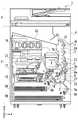
図1は、本実施形態で使用するインクジェット記録装置1(以下、記録装置1)の内部構成図である。図において、x方向は水平方向、y方向(紙面垂直方向)は後述する記録ヘッド8において吐出口が配列される方向、z方向は鉛直方向をそれぞれ示す。 FIG. 1 is an internal configuration diagram of an inkjet recording apparatus 1 (hereinafter, recording apparatus 1) used in the present embodiment. In the figure, an x direction indicates a horizontal direction, a y direction (a direction perpendicular to the paper surface) indicates a direction in which ejection ports are arranged in a
記録装置1は、プリント部2とスキャナ部3を備える複合機であり、記録動作と読取動作に関する様々な処理を、プリント部2とスキャナ部3で個別にあるいは連動して実行することができる。スキャナ部3は、ADF(オートドキュメントフィーダ)とFBS(フラットベッドスキャナ)を備えており、ADFで自動給紙される原稿の読み取りと、ユーザによってFBSの原稿台に置かれた原稿の読み取り(スキャン)を行うことができる。なお、本実施形態はプリント部2とスキャナ部3を併せ持った複合機であるが、スキャナ部3を備えない形態であってもよい。図1は、記録装置1が記録動作も読取動作も行っていない待機状態にあるときを示す。 The recording apparatus 1 is a multifunction peripheral including a
プリント部2において、筐体4の鉛直方向下方の底部には、記録媒体(カットシート)Sを収容するための第1カセット5Aと第2カセット5Bが着脱可能に設置されている。第1カセット5AにはA4サイズまでの比較的小さな記録媒体が、第2カセット5BにはA3サイズまでの比較的大きな記録媒体が、平積みに収容されている。第1カセット5A近傍には、収容されている記録媒体を1枚ずつ分離して給送するための第1給送ユニット6Aが設けられている。同様に、第2カセット5B近傍には、第2給送ユニット6Bが設けられている。記録動作が行われる際にはいずれか一方のカセットから選択的に記録媒体Sが給送される。 In the
搬送ローラ7、排出ローラ12、ピンチローラ7a、拍車7b、ガイド18、インナーガイド19およびフラッパ11は、記録媒体Sを所定の方向に導くための搬送機構である。搬送ローラ7は、記録ヘッド8の上流側および下流側に配され、不図示の搬送モータによって駆動される駆動ローラである。ピンチローラ7aは、搬送ローラ7と共に記録媒体Sをニップして回転する従動ローラである。排出ローラ12は、搬送ローラ7の下流側に配され、不図示の搬送モータによって駆動される駆動ローラである。拍車7bは、記録ヘッド8の下流側に配される搬送ローラ7及び排出ローラ12と共に記録媒体Sを挟持して搬送する。 The
ガイド18は、記録媒体Sの搬送経路に設けられ、記録媒体Sを所定の方向に案内する。インナーガイド19は、y方向に延在する部材で湾曲した側面を有し、当該側面に沿って記録媒体Sを案内する。フラッパ11は、両面記録動作の際に、記録媒体Sが搬送される方向を切り替えるための部材である。排出トレイ13は、記録動作が完了し排出ローラ12によって排出された記録媒体Sを積載保持するためのトレイである。 The
本実施形態の記録ヘッド8は、フルラインタイプのカラーインクジェット記録ヘッドであり、記録データに従ってインクを吐出する吐出口が、図1におけるy方向に沿って記録媒体Sの幅に相当する分だけ複数配列されている。記録ヘッド8が待機位置にあるとき、記録ヘッド8の吐出口面8aは、図1のように鉛直下方を向きキャップユニット10によってキャップされている。記録動作を行う際は、後述するプリントコントローラ202によって、吐出口面8aがプラテン9と対向するように記録ヘッド8の向きが変更される。プラテン9は、y方向に延在する平板によって構成され、記録ヘッド8によって記録動作が行われる記録媒体Sを背面から支持する。記録ヘッド8の待機位置から記録位置への移動については、後に詳しく説明する。 The
インクタンクユニット14は、記録ヘッド8へ供給される4色のインクをそれぞれ貯留する。インク供給ユニット15は、インクタンクユニット14と記録ヘッド8を接続する流路の途中に設けられ、記録ヘッド8内のインクの圧力及び流量を適切な範囲に調整する。本実施形態では循環型のインク供給系を採用しており、インク供給ユニット15は記録ヘッド8へ供給されるインクの圧力と記録ヘッド8から回収されるインクの流量を適切な範囲に調整する。 The
メンテナンスユニット16は、キャップユニット10とワイピングユニット17を備え、所定のタイミングにこれらを作動させて、記録ヘッド8に対するメンテナンス動作を行う。メンテナンス動作については後に詳しく説明する。 The
図2は、記録装置1における制御構成を示すブロック図である。制御構成は、主にプリント部2を統括するプリントエンジンユニット200と、スキャナ部3を統括するスキャナエンジンユニット300と、記録装置1全体を統括するコントローラユニット100によって構成されている。プリントコントローラ202は、コントローラユニット100のメインコントローラ101の指示に従ってプリントエンジンユニット200の各種機構を制御する。スキャナエンジンユニット300の各種機構は、コントローラユニット100のメインコントローラ101によって制御される。以下に制御構成の詳細について説明する。 FIG. 2 is a block diagram illustrating a control configuration in the recording apparatus 1. The control configuration mainly includes a
コントローラユニット100において、CPUにより構成されるメインコントローラ101は、ROM107に記憶されているプログラムや各種パラメータに従って、RAM106をワークエリアとしながら記録装置1全体を制御する。例えば、ホストI/F102またはワイヤレスI/F103を介してホスト装置400から印刷ジョブが入力されると、メインコントローラ101の指示に従って、画像処理部108が受信した画像データに対して所定の画像処理を施す。そして、メインコントローラ101はプリントエンジンI/F105を介して、画像処理を施した画像データをプリントエンジンユニット200へ送信する。 In the
なお、記録装置1は無線通信や有線通信を介してホスト装置400から画像データを取得しても良いし、記録装置1に接続された外部記憶装置(USBメモリ等)から画像データを取得しても良い。無線通信や有線通信に利用される通信方式は限定されない。例えば、無線通信に利用される通信方式として、Wi−Fi(Wireless Fidelity)(登録商標)やBluetooth(登録商標)が適用可能である。また、有線通信に利用される通信方式としては、USB(Universal Serial Bus)等が適用可能である。また、例えばホスト装置400から読取コマンドが入力されると、メインコントローラ101は、スキャナエンジンI/F109を介してこのコマンドをスキャナ部3に送信する。 Note that the recording device 1 may acquire image data from the
操作パネル104は、ユーザが記録装置1に対して入出力を行うための機構である。ユーザは、操作パネル104を介してコピーやスキャン等の動作を指示したり、印刷モードを設定したり、記録装置1の情報を認識したりすることができる。 The
プリントエンジンユニット200において、CPUにより構成されるプリントコントローラ202は、ROM203に記憶されているプログラムや各種パラメータに従って、RAM204をワークエリアとしながら、プリント部2が備える各種機構を制御する。コントローラI/F201を介して各種コマンドや画像データが受信されると、プリントコントローラ202は、これを一旦RAM204に保存する。記録ヘッド8が記録動作に利用できるように、プリントコントローラ202は画像処理コントローラ205に、保存した画像データを記録データへ変換させる。記録データが生成されると、プリントコントローラ202は、ヘッドI/F206を介して記録ヘッド8に記録データに基づく記録動作を実行させる。この際、プリントコントローラ202は、搬送制御部207を介して図1に示す給送ユニット6A、6B、搬送ローラ7、排出ローラ12、フラッパ11を駆動して、記録媒体Sを搬送する。プリントコントローラ202の指示に従って、記録媒体Sの搬送動作に連動して記録ヘッド8による記録動作が実行され、印刷処理が行われる。 In the
ヘッドキャリッジ制御部208は、記録装置1のメンテナンス状態や記録状態といった動作状態に応じて記録ヘッド8の向きや位置を変更する。インク供給制御部209は、記録ヘッド8へ供給されるインクの圧力が適切な範囲に収まるように、インク供給ユニット15を制御する。メンテナンス制御部210は、記録ヘッド8に対するメンテナンス動作を行う際に、メンテナンスユニット16におけるキャップユニット10やワイピングユニット17の動作を制御する。 The head
スキャナエンジンユニット300においては、メインコントローラ101が、ROM107に記憶されているプログラムや各種パラメータに従って、RAM106をワークエリアとしながら、スキャナコントローラ302のハードウェアリソースを制御する。これにより、スキャナ部3が備える各種機構は制御される。例えばコントローラI/F301を介してメインコントローラ101がスキャナコントローラ302内のハードウェアリソースを制御することにより、ユーザによってADFに搭載された原稿を、搬送制御部304を介して搬送し、センサ305によって読み取る。そして、スキャナコントローラ302は読み取った画像データをRAM303に保存する。なお、プリントコントローラ202は、上述のように取得された画像データを記録データに変換することで、記録ヘッド8に、スキャナコントローラ302で読み取った画像データに基づく記録動作を実行させることが可能である。 In the
図3は、記録装置1が記録状態にあるときを示す。図1に示した待機状態と比較すると、キャップユニット10が記録ヘッド8の吐出口面8aから離間し、吐出口面8aがプラテン9と対向している。本実施形態において、プラテン9の平面は水平方向に対して約45度傾いており、記録位置における記録ヘッド8の吐出口面8aも、プラテン9との距離が一定に維持されるように水平方向に対して約45度傾いている。 FIG. 3 shows a state where the recording apparatus 1 is in a recording state. As compared with the standby state shown in FIG. 1, the
記録ヘッド8を図1に示す待機位置から図3に示す記録位置に移動する際、プリントコントローラ202は、メンテナンス制御部210を用いて、キャップユニット10を図3に示す退避位置まで降下させる。これにより、記録ヘッド8の吐出口面8aは、キャップ部材10aと離間する。その後、プリントコントローラ202は、ヘッドキャリッジ制御部208を用いて記録ヘッド8の鉛直方向の高さを調整しながら45度回転させ、吐出口面8aをプラテン9と対向させる。記録動作が完了し、記録ヘッド8が記録位置から待機位置に移動する際は、プリントコントローラ202によって上記と逆の工程が行われる。 When the
次に、プリント部2における記録媒体Sの搬送経路について説明する。記録コマンドが入力されると、プリントコントローラ202は、まず、メンテナンス制御部210およびヘッドキャリッジ制御部208を用いて、記録ヘッド8を図3に示す記録位置に移動する。その後、プリントコントローラ202は搬送制御部207を用い、記録コマンドに従って第1給送ユニット6Aおよび第2給送ユニット6Bのいずれかを駆動し、記録媒体Sを給送する。 Next, the conveyance path of the recording medium S in the
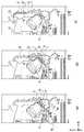
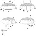
図4(a)〜(c)は、第1カセット5Aに収容されているA4サイズの記録媒体Sが給送されるときの搬送経路を示す図である。第1カセット5A内の1番上に積載された記録媒体Sは、第1給送ユニット6Aによって2枚目以降の記録媒体から分離され、搬送ローラ7とピンチローラ7aにニップされながら、プラテン9と記録ヘッド8の間の記録領域Pに向けて搬送される。図4(a)は、記録媒体Sの先端が記録領域Pに到達する直前の搬送状態を示す。記録媒体Sの進行方向は、第1給送ユニット6Aに給送されて記録領域Pに到達する間に、水平方向(x方向)から、水平方向に対して約45度傾いた方向に変更される。 FIGS. 4A to 4C are diagrams illustrating transport paths when the A4-size recording medium S stored in the
記録領域Pでは、記録ヘッド8に設けられた複数の吐出口から記録媒体Sに向けてインクが吐出される。インクが付与される領域の記録媒体Sは、プラテン9によってその背面が支持されており、吐出口面8aと記録媒体Sの距離が一定に保たれている。インクが付与された後の記録媒体Sは、搬送ローラ7と拍車7bに案内されながら、先端が右に傾いているフラッパ11の左側を通り、ガイド18に沿って記録装置1の鉛直方向上方へ搬送される。図4(b)は、記録媒体Sの先端が記録領域Pを通過して鉛直方向上方に搬送される状態を示す。記録媒体Sの進行方向は、水平方向に対し約45度傾いた記録領域Pの位置から、搬送ローラ7と拍車7bによって鉛直方向上方に変更されている。 In the recording area P, ink is ejected toward the recording medium S from a plurality of ejection ports provided in the
記録媒体Sは、鉛直方向上方に搬送された後、排出ローラ12と拍車7bによって排出トレイ13に排出される。図4(c)は、記録媒体Sの先端が排出ローラ12を通過して排出トレイ13に排出される状態を示す。排出された記録媒体Sは、記録ヘッド8によって画像が記録された面を下にした状態で、排出トレイ13上に保持される。 After being conveyed vertically upward, the recording medium S is discharged to a
図5(a)〜(c)は、第2カセット5Bに収容されているA3サイズの記録媒体Sが給送されるときの搬送経路を示す図である。第2カセット5B内の1番上に積載された記録媒体Sは、第2給送ユニット6Bによって2枚目以降の記録媒体から分離され、搬送ローラ7とピンチローラ7aにニップされながら、プラテン9と記録ヘッド8の間の記録領域Pに向けて搬送される。 FIGS. 5A to 5C are diagrams illustrating the transport path when the A3-size recording medium S stored in the
図5(a)は、記録媒体Sの先端が記録領域Pに到達する直前の搬送状態を示す。第2給送ユニット6Bに給送されて記録領域Pに到達するまでの搬送経路には、複数の搬送ローラ7とピンチローラ7aおよびインナーガイド19が配されることで、記録媒体SはS字上に湾曲されてプラテン9まで搬送される。 FIG. 5A illustrates a conveyance state immediately before the leading end of the recording medium S reaches the recording area P. A plurality of
その後の搬送経路は、図4(b)および(c)で示したA4サイズの記録媒体Sの場合と同様である。図5(b)は、記録媒体Sの先端が記録領域Pを通過して鉛直方向上方に搬送される状態を示す。図5(c)は、記録媒体Sの先端が排出ローラ12を通過して排出トレイ13に排出される状態を示す。 Subsequent transport paths are the same as those for the A4-size recording medium S shown in FIGS. 4B and 4C. FIG. 5B shows a state in which the leading end of the recording medium S passes through the recording area P and is conveyed vertically upward. FIG. 5C illustrates a state in which the leading end of the recording medium S passes through the
図6(a)〜(d)は、A4サイズの記録媒体Sの裏面(第2面)に対して記録動作(両面記録)を行う場合の搬送経路を示す。両面記録を行う場合、第1面(表面)を記録した後に第2面(裏面)に記録動作を行う。第1面を記録する際の搬送工程は図4(a)〜(c)と同様であるので、ここでは説明を省略する。以後、図4(c)以後の搬送工程について説明する。 FIGS. 6A to 6D show transport paths when a recording operation (double-sided recording) is performed on the back surface (second surface) of the A4 size recording medium S. When performing double-sided recording, a recording operation is performed on the second surface (back surface) after recording the first surface (front surface). The transporting process when recording the first surface is the same as that shown in FIGS. 4A to 4C, and a description thereof will not be repeated. Hereinafter, the transfer process after FIG. 4C will be described.
記録ヘッド8による第1面への記録動作が完了し、記録媒体Sの後端がフラッパ11を通過すると、プリントコントローラ202は、搬送ローラ7を逆回転させて記録媒体Sを記録装置1の内部へ搬送する。この際、フラッパ11は、不図示のアクチュエータによってその先端が左側に傾くように制御されるため、記録媒体Sの先端(第1面の記録動作における後端)はフラッパ11の右側を通過して鉛直方向下方へ搬送される。図6(a)は、記録媒体Sの先端(第1面の記録動作における後端)が、フラッパ11の右側を通過する状態を示す。 When the recording operation on the first surface by the
その後記録媒体Sは、インナーガイド19の湾曲した外周面に沿って搬送され、再び記録ヘッド8とプラテン9の間の記録領域Pに搬送される。この際、記録ヘッド8の吐出口面8aに、記録媒体Sの第2面が対向する。図6(b)は、第2面の記録動作のために、記録媒体Sの先端が記録領域Pに到達する直前の搬送状態を示す。 Thereafter, the recording medium S is conveyed along the curved outer peripheral surface of the
その後の搬送経路は、図4(b)および(c)で示した第1面記録の場合と同様である。図6(c)は、記録媒体Sの先端が記録領域Pを通過して鉛直方向上方に搬送される状態を示す。この際、フラッパ11は、不図示のアクチュエータにより先端が右側に傾いた位置に移動するように制御される。図6(d)は、記録媒体Sの先端が排出ローラ12を通過して排出トレイ13に排出される状態を示す。 Subsequent transport paths are the same as in the case of the first-side recording shown in FIGS. 4B and 4C. FIG. 6C shows a state in which the leading end of the recording medium S passes through the recording area P and is conveyed vertically upward. At this time, the
次に、記録ヘッド8に対するメンテナンス動作について説明する。図1でも説明したように、本実施形態のメンテナンスユニット16は、キャップユニット10とワイピングユニット17とを備え、所定のタイミングにこれらを作動させてメンテナンス動作を行う。 Next, a maintenance operation for the
図7は、記録装置1がメンテナンス状態のときの図である。記録ヘッド8を図1に示す待機位置から図7に示すメンテナンス位置に移動する際、プリントコントローラ202は、記録ヘッド8を鉛直方向において上方に移動させるとともにキャップユニット10を鉛直方向下方に移動させる。そして、プリントコントローラ202は、ワイピングユニット17を退避位置から図7における右方向に移動させる。その後、プリントコントローラ202は、記録ヘッド8を鉛直方向下方に移動させメンテナンス動作が可能なメンテナンス位置に移動させる。 FIG. 7 is a diagram when the recording apparatus 1 is in a maintenance state. When the
一方、記録ヘッド8を図3に示す記録位置から図7に示すメンテナンス位置に移動する際、プリントコントローラ202は、記録ヘッド8を45度回転させつつ鉛直方向上方に移動させる。そして、プリントコントローラ202は、ワイピングユニット17を退避位置から右方向に移動させる。その後プリントコントローラ202は、記録ヘッド8を鉛直方向下方に移動させて、メンテナンスユニット16によるメンテナンス動作が可能なメンテナンス位置に移動させる。 On the other hand, when moving the
図8は、記録装置1の外観斜視図である。ここでは、ユーザによって開閉可能なフロントドア20およびヘッドホルダドア31を共に開放した状態を示している。本実施形態の記録ヘッド8は記録装置1に対して交換可能であり、記録ヘッド8を交換する際、ユーザは図のように装置正面のフロントドア20をまず開放し、次いで更に内部に配されるヘッドホルダドア31も開放する。そして、ヘッドホルダドア31の内側に設けられているヘッドホルダ30に、記録ヘッド8を正面から奥に向けて図の+y方向に挿入する。 FIG. 8 is an external perspective view of the recording apparatus 1. Here, the
図9は、ヘッドホルダ30に記録ヘッド8を挿入する状態を示す図である。ヘッドホルダ30は、記録ヘッド8全体を収容可能な形状を有し、記録ヘッド8の吐出口面8aが対応する位置には吐出口面8aを露出させるための開口が配されている。ユーザは、ヘッドホルダ30の摺動底面32に記録ヘッド8を載せた状態で挿入し、記録ヘッド8の突き当りを確認した後、ヘッドホルダドア31を閉じる。 FIG. 9 is a diagram illustrating a state in which the
なお、以下の説明において、x方向は記録ヘッド8の短手方向(側面方向)、y方向は記録ヘッド8の長手方向(記録媒体の幅方向)、z方向は記録ヘッド8の吐出方向とする。既に説明したように、本実施形態の記録ヘッド8は記録装置1の内部で回転可能であるため、記録ヘッド固有のxyz軸は、記録装置1のxyz軸と常に一致するものではないが、基本的には図1に示す待機状態にある場合のxyz軸と一致している。 In the following description, the x direction is the short direction (side direction) of the
図10(a)および(b)は、記録ヘッド8に対する保護部材(カバー)40の取り付け状態を説明するための図であり、記録ヘッド8を吐出口面8a側から見た図になっている。図10(a)に示すように、保護部材40は、吐出口面8a)を覆いながら長手方向(y方向)にスライド可能な形状を有している。保護部材40は、長手方向に延在する記録ヘッド8のベースプレート80に沿って図の右方向にスライドし、ベースプレート80の端部で固定される。保護部材40の左側端部には、保護部材40のスライドを規制するためのストッパ43が設けられている。 FIGS. 10A and 10B are diagrams for explaining the state of attachment of the protective member (cover) 40 to the
図10(b)は、記録ヘッド8に対し保護部材40が固定される様子を示す図である。保護部材40のスライド方向(+y方向)の先端には、テーパー面を有し短手方向(図の−x方向)の力によって回動可能な爪形状のロック部材41が設けられている。一方、記録ヘッド8のベースプレート80には、ロック部材41が通過する位置に係合部81が設けられている。このような構成の下、保護部材40が+y方向にスライドしロック部材41のテーパー面が係合部81に突き当たると、ロック部材41は−x方向の力を受けて図10(b)において時計回りに回動する。そして、ロック部材41が回動した状態のまま、保護部材40はy方向に進行する。ロック部材41が係合部81を越えた位置まで+y方向にスライドすると、ロック部材41は反時計回りに回動して元の位置に戻り、図10(b)に示す状態となる。 FIG. 10B is a diagram illustrating a state in which the
図10(b)に示す状態において、ロック部材41の左端部は係合部81の右端部と当接しており、保護部材40は左方向(−y方向)への移動が規制される。一方、図10(a)で示したストッパ43はベースプレート80の左端部に当接し、保護部材40は右方向(+y方向)への移動も規制される。すなわち、ロック部材41と係合部81が図10(b)に示すように係合した状態において、保護部材40は記録ヘッド8に固定され、吐出口面8aは保護部材40によって保護された状態となる。ロック部材41によりロックされているため、ユーザが記録ヘッド8を記録装置1に装着する前に保護部材40を外すことができない構成になっている。本実施形態の記録ヘッド8は、このように吐出口面8aが保護部材40によって保護された状態で輸送され、ユーザの元に届く。 In the state shown in FIG. 10B, the left end of the
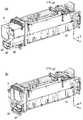
図11(a)および(b)は、記録ヘッド8をヘッドホルダ30に装着する様子を示す図である。図11(a)はヘッドホルダ30に記録ヘッド8を挿入している様子、同図(b)は定位置までの挿入が完了した様子をそれぞれ示している。両図において、ヘッドホルダドア31は省略している。 FIGS. 11A and 11B are views showing a state in which the
本実施形態の記録ヘッド8は、保護部材40が取り付けられたままの状態で、ユーザによってヘッドホルダ30に挿入される。そして、この挿入の過程で、保護部材40は記録ヘッド8から機械的に分離される仕組みになっている。 The
図12(a)〜(c)は、記録ヘッド8の挿入に伴って、保護部材40が記録ヘッド8から分離される仕組みを説明するための図である。図12において、記録ヘッド8はヘッドホルダ30に対し、左から右に向けて挿入され移動する。 FIGS. 12A to 12C are diagrams for explaining a mechanism in which the
図12(a)に示すように、ロック部材41と係合部81は、図10(b)で示した係合状態を維持しながら右方向に移動する。移動の方向(y方向)において、ロック部材41と対向するベースプレート80の位置には、第1の押圧部材33が配されている。また、保護部材40には、ロック部材41よりも移動方向(y方向)の先の位置には保護部材端部42が配され、この保護部材端部42と対向するベースプレート80の位置には、第2の押圧部材34が配されている。 As shown in FIG. 12A, the
図12(b)は、ロック部材41が第1の押圧部材33に当接した状態を示している。ロック部材41のテーパー面が第1の押圧部材33に当接すると、ロック部材41は短手方向内側(−x方向)の力を受けて時計回りに回動し、ロック部材41の外側(+x方向側)には係合部81が通過可能なスペースが形成される。 FIG. 12B shows a state in which the
図12(c)は、係合部81が、ロック部材41が回動することによって形成されたスペースを右方向へ移動し、保護部材端部42が第2の押圧部材34に当接した状態を示している。保護部材端部42が第2の押圧部材34に当接することによって、保護部材40のy方向への進行は規制される。一方、係合部81とロック部材41の係合が解除されるため、保護部材40は記録ヘッド8から離脱し、記録ヘッド8のみが更にy方向に進行可能となる。つまり、保護部材40は図12(c)に示す位置より先に挿入されることはなく、記録ヘッド8のヘッドホルダ30に対する位置決めはさらにy方向下流側において行われる。 FIG. 12C illustrates a state in which the engaging
すなわち、保護部材40は、ロック部材41が第1の押圧部材33に当接し回動することによって係合部81との係合が解除され、その後保護部材端部42が第2の押圧部材34に当接して進行が規制されることによって、記録ヘッド8から分離される。そして、記録ヘッド8を更に奥へ挿入することによって、保護部材40のストッパ43と記録ヘッド8の間に隙間が形成される。これにより、ユーザはストッパ43を把持部として利用し、保護部材40を手前(装置外)に引き出すことができる(図11(b)参照)。 That is, the
このように、本実施形態によれば、ユーザが、保護部材40が取り付けられた状態の記録ヘッド8をヘッドホルダ30に挿入することにより、はじめて記録ヘッド8から保護部材40を取り外すことが出来る。つまり、ユーザは、記録ヘッド8から保護部材40を取り外すために保護部材40に触れる必要はなく、誤って保護部材40を外してから記録ヘッド8が装着されることを抑制することができる。このため、記録ヘッド8の吐出口面にある液体が他の物体に接触することによる汚染や破損を懸念することなく、簡便な構成で記録ヘッドを適切な位置に装着することが可能となる。 As described above, according to the present embodiment, the user can remove the
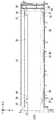
次に、ヘッドホルダ30内における記録ヘッド8の位置決めについて説明する。図13は、記録ヘッド8が装着されていない状態のヘッドホルダ30を上位方向(+z方向)から見た図である。 Next, positioning of the
ヘッドホルダ30の開口の短手方向両側には、y方向に延在する摺動底面32が配されており、記録ヘッド8は、摺動底面32に接触した状態で摺動されながら+y方向に挿入される。すなわち、摺動底面32は記録ヘッド8をヘッドホルダ30の+y方向にガイドするための案内部となる。摺動底面32において±x方向の両側および±y方向の両端部には、記録ヘッド8の摺動部(図13では不図示)が当たらないように切り欠かれた切欠き部39が形成されている。また、切欠き部39の±x方向の更に外側には着地面37が設けられており、ヘッドホルダ30において記録ヘッド8をz方向(重力方向)に案内および位置決めするための構成となる。 A sliding
一方、ヘッドホルダ30のy方向に延びる内壁の一方側には、板ばねで構成される付勢部材50が3箇所に配されており、他方側には平板からなる摺動側面35が配されている。よって、ヘッドホルダ30に挿入された記録ヘッド8は、付勢部材50によって図の−x方向(側面方向)に付勢された状態で、摺動側面35に案内されながらy方向に進行する。摺動側面35において±y方向の両端部には、ベースプレート80の側面に形成された突起部84(図13では不図示)と当らないように凹んだ形状の凹部36が形成されている。摺動側面35において凹部36の近傍には、記録ヘッド8をx方向において位置決めするための位置決めリブ360(図16参照)が形成されている。以上説明した付勢部材50および位置決めリブ360が、ヘッドホルダ30において記録ヘッド8をy方向に案内しつつx方向に位置決めするための構成となる。 On the other hand, on one side of an inner wall of the
更に、ヘッドホルダ30のx方向に延びる内壁のうち奥側の面(+y方向下流側の面)には、挿入された記録ヘッド8と当接させるための、リブ形状の正面位置決め部材38が設けられている。挿入された記録ヘッド8のベースプレート80の端部が正面位置決め部材38に突き当たり、更にユーザが、図8および図9で説明したヘッドホルダドア31を閉じることにより、ヘッドホルダ30内における記録ヘッド8のy方向の位置が固定される。このとき、ヘッドホルダドア31に配されたバネは、記録ヘッド8を+y方向へ付勢している。すなわち、正面位置決め部材38およびヘッドホルダドア31に配されたバネが、ヘッドホルダ30において記録ヘッド8をy方向に位置決めするための構成となる。 Further, a rib-shaped
図14(a)および(b)は、記録ヘッド8とヘッドホルダ30の断面拡大図である。図14(a)は記録ヘッド8を挿入している途中、同図(b)は挿入が完了し記録ヘッド8が位置決めされた状態をそれぞれ示している。記録ヘッド8のベースプレート80の底部において、吐出口面8aの±x方向の両側には、比較的大きく突出した摺動部82と比較的小さく突出し平面を有する着地部83が、それぞれ隣り合って配されている。 FIGS. 14A and 14B are enlarged cross-sectional views of the
そして、記録ヘッド8が挿入される際は、図14(a)に示すように、ヘッドホルダ30の摺動底面32には摺動部82が接触し、着地部83が非接触な状態となる。挿入が進むと、摺動部82は図13で説明した切欠き部39に落ち込み、図14(b)に示すように着地部83が摺動底面32の着地面37に着地する。この、着地部83と着紙面37の当接によって、ヘッドホルダ内におけるz方向の位置決めが完了する。つまり、記録ヘッド8は、ヘッドホルダ30に対し、挿入途中の高さよりもHだけ降下した位置に着地する。 Then, when the
本実施形態では、ヘッドホルダ30の摺動底面32はアルミで形成されているため、記録ヘッド8の交換のたびに摺動部82の摺動が繰り返されると、摺動底面32の磨耗が進みz方向の位置精度が低下するおそれがある。本実施形態のように、摺動させるための摺動部82と位置決めするための着地部83とを、個別に用意することにより、ヘッドホルダ30に対する記録ヘッド8のスムーズな挿入と正確な位置決めとを両立させることが可能となる。 In the present embodiment, since the sliding
図15(a)および(b)は、記録ヘッド8が挿入されている状態のヘッドホルダ30の上面図である。図15(a)は挿入中、同図(b)は挿入が完了し位置決めされた状態をそれぞれ示している。記録ヘッド8のベースプレート80には、摺動側面35に対向する面の長手方向の両側には突起部84が配されている。一方、摺動側面35には、長手方向の両側に、突起部84を避けるための凹部36が形成されている。 FIGS. 15A and 15B are top views of the
以上の構成の下、キャリッジホルダ30に記録ヘッド8が挿入されると、記録ヘッド8は付勢部材50によって図の−x方向に付勢され、突起部84が摺動側面35当接し、摺動側面35に案内されながら、+y方向に移動する。図15(a)は、このような挿入が途中まで行われた状態を示している。図15(a)において、記録ヘッド8の先頭は正面位置決め部材38に当接していない。 With the above configuration, when the
一方、図15(b)は、挿入が完了した状態を示している。図15(b)において、突起部84は凹部36に収まり、記録ヘッド8の挿入方向の先頭は正面位置決め部材38に当接している。 On the other hand, FIG. 15B shows a state where the insertion has been completed. In FIG. 15B, the
図16(a)〜(d)は、図15(a)および(b)の左右2箇所で示した、突起部84と位置決めリブ360の周辺を示す拡大図である。図16(a)および(b)は、摺動状態にある突起部84周辺を示している。突起部84は付勢部材50によって−x方向に付勢され、当接する摺動側面35より抗力を受けながら図の右方向に移動する。 FIGS. 16A to 16D are enlarged views showing the periphery of the
一方、図16(c)および(d)は、位置決めリブ360によって位置決めされた状態にある、突起部84と凹部36をそれぞれ示している。付勢部材50によって−x方向に付勢されている突起部84が凹部360と当接しないように、凹部360は突起部84と避けるように構成されている。また、記録ヘッド8の当接面840と位置決めリブ360が当接することでx方向の位置決めがなされる。 On the other hand, FIGS. 16C and 16D show the protruding
以上説明したように、本実施形態によれば、記録ヘッド8の摺動部82および突起部84がヘッドホルダ30の摺動底面32および摺動側面35にそれぞれ沿って摺動することにより、記録ヘッド8がヘッドホルダ30の内部に案内される。そして、記録ヘッド8の着地部83がヘッドホルダ30の着地面37と当接することでz方向が位置決めされ、記録ヘッド8の当接面840と位置決めリブ360が当接することでx方向が位置決めされる。更にこのような挿入が完了後、ユーザがヘッドホルダドア31を閉じることにより、ヘッドホルダドア31に配されたバネによって、記録ヘッド8の奥行き方向の端部が正面位置決め部材38に押し付けられ、記録ヘッド8がy方向に位置決めされる。 As described above, according to the present embodiment, the sliding
以上説明したように、本発明によれば、吐出口面の接触に伴う汚染や傷つきを抑えつつ、簡便な構成で記録ヘッドを適切な位置に装着することが可能となる。 As described above, according to the present invention, it is possible to mount the recording head at an appropriate position with a simple configuration while suppressing contamination and damage due to contact with the ejection port surface.
1 インクジェット記録装置
8 記録ヘッド
8a 吐出口面
30 ヘッドホルダ
32 摺動底面(案内部)
33 第1の押圧部材
34 第2の押圧部材
40 保護部材
41 ロック部材
42 保護部材端部
80 ベースプレート
81 係合部
82 摺動部DESCRIPTION OF SYMBOLS 1 Ink
33
Claims (7)
Translated fromJapanese前記記録ヘッドを着脱可能に保持するヘッドホルダと、
前記ヘッドホルダに配され、前記保護部材によって前記吐出口面が取り付けられた前記記録ヘッドを前記幅方向に案内する案内部と、
を備え、
前記案内部は、前記幅方向の所定位置までは前記保護部材が取り付けられた状態で前記記録ヘッドを案内し、前記所定位置よりも先では前記保護部材が前記所定位置を超えないように前記記録ヘッドのみを案内することを特徴とするインクジェット記録装置。A recording head to which a discharge port for discharging liquid has a discharge port surface arranged in the width direction of the recording medium, and a protection member for protecting the discharge port surface can be attached;
A head holder for detachably holding the recording head,
A guide portion arranged on the head holder, for guiding the recording head, to which the discharge port surface is attached by the protection member, in the width direction;
With
The guide unit guides the recording head with the protection member attached to the predetermined position in the width direction, and performs the recording so that the protection member does not exceed the predetermined position before the predetermined position. An ink jet recording apparatus for guiding only a head.
前記案内部は、前記ロック部材に当接し、前記ロック部材と前記係合部の係合を解除する第1の押圧部材と、前記保護部材と当接することにより、前記保護部材の前記所定位置よりも先への移動を規制する第2の押圧部材とを、有することを特徴とする請求項1に記載のインクジェット記録装置。The protection member is fixed to the recording head by a locking member provided on the protection member being engaged with an engagement portion provided on the recording head,
The guide portion abuts on the lock member, releases the engagement between the lock member and the engagement portion with a first pressing member, and abuts on the protection member. The ink jet recording apparatus according to claim 1, further comprising a second pressing member that regulates movement of the ink jet recording apparatus.
前記摺動底面に配され、前記記録ヘッドの着地部が着地する着地面と、
を更に有し、
前記記録ヘッドは、前記ヘッドホルダ内において、前記着地部が前記着地面に着地することによって鉛直方向に位置決めされることを特徴とする請求項1から4のいずれか1項に記載のインクジェット記録装置。A sliding bottom surface for guiding the first sliding portion disposed on the recording head in the width direction while supporting the first sliding portion from below in a vertical direction;
A landing surface arranged on the sliding bottom surface, where a landing portion of the recording head lands;
Further having
5. The ink jet recording apparatus according to claim 1, wherein the recording head is positioned vertically in the head holder when the landing portion lands on the landing surface. 6. .
前記記録ヘッドを前記摺動側面の方向に付勢する付勢部材と、
前記摺動側面に配され、前記記録ヘッドの位置決め面が当接可能な位置決めリブと、
を更に有し、
前記記録ヘッドは、前記ヘッドホルダ内において、前記位置決め面が前記位置決めリブと当接することによって前記側面方向に位置決めされることを特徴とする請求項1から5のいずれか1項に記載のインクジェット記録装置。A sliding side surface that guides the second sliding portion disposed on the recording head in the width direction while supporting the second sliding portion in a side direction that intersects the width direction;
An urging member for urging the recording head in the direction of the sliding side surface,
A positioning rib disposed on the sliding side surface and capable of abutting a positioning surface of the recording head;
Further having
The inkjet recording according to any one of claims 1 to 5, wherein the recording head is positioned in the side direction by contacting the positioning surface with the positioning rib in the head holder. apparatus.
前記記録ヘッドの着脱のための開口を開閉するドアと、
を有し、
前記記録ヘッドは、前記ヘッドホルダ内において、前記先端が前記位置決め部材と当接した状態で前記ドアが閉められることによって、前記幅方向に位置決めされることを特徴とする請求項1から6のいずれか1項に記載のインクジェット記録装置。A positioning member that is in contact with a leading end of the recording head in a moving direction guided by the guide unit,
A door that opens and closes an opening for attaching and detaching the recording head;
Has,
7. The recording head according to claim 1, wherein the recording head is positioned in the width direction by closing the door in the head holder with the tip abutting on the positioning member. 2. The ink jet recording apparatus according to claim 1.
Priority Applications (4)
| Application Number | Priority Date | Filing Date | Title |
|---|---|---|---|
| JP2018151445AJP7171306B2 (en) | 2018-08-10 | 2018-08-10 | Liquid ejector |
| US16/531,765US10994542B2 (en) | 2018-08-10 | 2019-08-05 | Inkjet printing apparatus |
| CN201910721428.8ACN110816049B (en) | 2018-08-10 | 2019-08-06 | Ink jet printing apparatus |
| EP19190308.7AEP3608117B1 (en) | 2018-08-10 | 2019-08-06 | Inkjet printing apparatus |
Applications Claiming Priority (1)
| Application Number | Priority Date | Filing Date | Title |
|---|---|---|---|
| JP2018151445AJP7171306B2 (en) | 2018-08-10 | 2018-08-10 | Liquid ejector |
Publications (2)
| Publication Number | Publication Date |
|---|---|
| JP2020026070Atrue JP2020026070A (en) | 2020-02-20 |
| JP7171306B2 JP7171306B2 (en) | 2022-11-15 |
Family
ID=67551179
Family Applications (1)
| Application Number | Title | Priority Date | Filing Date |
|---|---|---|---|
| JP2018151445AActiveJP7171306B2 (en) | 2018-08-10 | 2018-08-10 | Liquid ejector |
Country Status (4)
| Country | Link |
|---|---|
| US (1) | US10994542B2 (en) |
| EP (1) | EP3608117B1 (en) |
| JP (1) | JP7171306B2 (en) |
| CN (1) | CN110816049B (en) |
Citations (2)
| Publication number | Priority date | Publication date | Assignee | Title |
|---|---|---|---|---|
| JP2003127402A (en)* | 2001-10-22 | 2003-05-08 | Canon Inc | Inkjet recording device |
| US20060009841A1 (en)* | 2003-05-05 | 2006-01-12 | Rex Medical | Percutaneous aortic valve |
Family Cites Families (18)
| Publication number | Priority date | Publication date | Assignee | Title |
|---|---|---|---|---|
| EP0479270B1 (en) | 1990-10-03 | 1996-05-22 | Canon Kabushiki Kaisha | Recording apparatus |
| US5892523A (en) | 1995-05-18 | 1999-04-06 | Canon Kabushiki Kaisha | Reading unit and printing apparatus capable of mounting such reading unit thereon |
| JPH0976528A (en) | 1995-09-19 | 1997-03-25 | Oki Data:Kk | Inkjet printer |
| JPH11240146A (en) | 1997-12-26 | 1999-09-07 | Canon Inc | Recording device |
| JP3382566B2 (en) | 1999-08-24 | 2003-03-04 | キヤノン株式会社 | Protective member for recording head |
| JP2002254666A (en) | 2000-09-13 | 2002-09-11 | Seiko Epson Corp | INK JET RECORDING APPARATUS AND DRIVE CONTROL METHOD IN THE APPARATUS |
| JP4945843B2 (en) | 2001-02-21 | 2012-06-06 | ソニー株式会社 | Inkjet head and inkjet printer |
| JP5316506B2 (en) | 2010-09-30 | 2013-10-16 | ブラザー工業株式会社 | Liquid ejection device |
| JP5645616B2 (en) | 2010-11-17 | 2014-12-24 | キヤノン株式会社 | Recording device |
| US9132640B2 (en) | 2012-09-12 | 2015-09-15 | Hewlett-Packard Development Company, L.P. | Cap assembly for print head device |
| JP6095542B2 (en) | 2013-09-27 | 2017-03-15 | 富士フイルム株式会社 | Droplet discharge device |
| JP6584146B2 (en) | 2015-05-27 | 2019-10-02 | キヤノン株式会社 | Printing device |
| US10183505B2 (en) | 2015-05-27 | 2019-01-22 | Canon Kabushiki Kaisha | Printing apparatus and platen |
| US10011124B2 (en) | 2015-05-27 | 2018-07-03 | Canon Kabushiki Kaisha | Performing marginless printing based on image data |
| EP3098083B1 (en) | 2015-05-27 | 2021-08-25 | Canon Kabushiki Kaisha | Printing apparatus and platen |
| CN206812621U (en) | 2017-05-03 | 2017-12-29 | 苏州英捷飞微机电有限公司 | A kind of jet-printing equipment spray nozzle protection device |
| JP7109944B2 (en) | 2018-03-13 | 2022-08-01 | キヤノン株式会社 | recording device |
| JP7277078B2 (en) | 2018-03-29 | 2023-05-18 | キヤノン株式会社 | Inkjet recording device |
- 2018
- 2018-08-10JPJP2018151445Apatent/JP7171306B2/enactiveActive
- 2019
- 2019-08-05USUS16/531,765patent/US10994542B2/enactiveActive
- 2019-08-06EPEP19190308.7Apatent/EP3608117B1/enactiveActive
- 2019-08-06CNCN201910721428.8Apatent/CN110816049B/enactiveActive
Patent Citations (2)
| Publication number | Priority date | Publication date | Assignee | Title |
|---|---|---|---|---|
| JP2003127402A (en)* | 2001-10-22 | 2003-05-08 | Canon Inc | Inkjet recording device |
| US20060009841A1 (en)* | 2003-05-05 | 2006-01-12 | Rex Medical | Percutaneous aortic valve |
Also Published As
| Publication number | Publication date |
|---|---|
| US10994542B2 (en) | 2021-05-04 |
| CN110816049A (en) | 2020-02-21 |
| CN110816049B (en) | 2021-12-10 |
| EP3608117A1 (en) | 2020-02-12 |
| EP3608117B1 (en) | 2023-01-25 |
| JP7171306B2 (en) | 2022-11-15 |
| US20200047503A1 (en) | 2020-02-13 |
Similar Documents
| Publication | Publication Date | Title |
|---|---|---|
| US9598257B2 (en) | Medium storage cassette and recording device | |
| JP4277223B2 (en) | Paper feeding device and image recording apparatus having the same | |
| US20200236236A1 (en) | Printing apparatus | |
| JP7134696B2 (en) | Inkjet recording device | |
| JP4277224B2 (en) | Paper feeding device and image recording apparatus having the same | |
| US9296233B2 (en) | Liquid ejecting device | |
| JP7034749B2 (en) | Recording device | |
| JP7071115B2 (en) | Feeder and recording device | |
| JP7134672B2 (en) | Inkjet recording device | |
| JP4224716B2 (en) | Paper feeding device and image recording apparatus having the same | |
| JP4224718B2 (en) | Paper feeder | |
| JP2006273564A (en) | Paper feeding device and image recording apparatus having the same | |
| JP7171306B2 (en) | Liquid ejector | |
| JP7046589B2 (en) | Recording device | |
| JP7130404B2 (en) | Recording head and recording device | |
| JP6372281B2 (en) | Conveying apparatus and image recording apparatus | |
| JP7179474B2 (en) | recording device | |
| JP2015067448A (en) | Sheet transport device | |
| JP7199838B2 (en) | image recorder | |
| JP2022093447A (en) | Recording device | |
| JP2023020094A (en) | recording device | |
| JP2025012725A (en) | Cartridge, cartridge set, and recording device | |
| JP2020158307A (en) | Transport device | |
| JP2006239934A (en) | Image reading and recording device | |
| JP2012116650A (en) | Paper feed tray |
Legal Events
| Date | Code | Title | Description |
|---|---|---|---|
| A621 | Written request for application examination | Free format text:JAPANESE INTERMEDIATE CODE: A621 Effective date:20210726 | |
| A977 | Report on retrieval | Free format text:JAPANESE INTERMEDIATE CODE: A971007 Effective date:20220519 | |
| A131 | Notification of reasons for refusal | Free format text:JAPANESE INTERMEDIATE CODE: A131 Effective date:20220621 | |
| A521 | Request for written amendment filed | Free format text:JAPANESE INTERMEDIATE CODE: A523 Effective date:20220815 | |
| TRDD | Decision of grant or rejection written | ||
| A01 | Written decision to grant a patent or to grant a registration (utility model) | Free format text:JAPANESE INTERMEDIATE CODE: A01 Effective date:20221004 | |
| A61 | First payment of annual fees (during grant procedure) | Free format text:JAPANESE INTERMEDIATE CODE: A61 Effective date:20221102 | |
| R151 | Written notification of patent or utility model registration | Ref document number:7171306 Country of ref document:JP Free format text:JAPANESE INTERMEDIATE CODE: R151 |