JP2020025992A - Control device, control method, and program - Google Patents
Control device, control method, and programDownload PDFInfo
- Publication number
- JP2020025992A JP2020025992AJP2018150220AJP2018150220AJP2020025992AJP 2020025992 AJP2020025992 AJP 2020025992AJP 2018150220 AJP2018150220 AJP 2018150220AJP 2018150220 AJP2018150220 AJP 2018150220AJP 2020025992 AJP2020025992 AJP 2020025992A
- Authority
- JP
- Japan
- Prior art keywords
- unit
- processor
- command value
- software
- control device
- Prior art date
- Legal status (The legal status is an assumption and is not a legal conclusion. Google has not performed a legal analysis and makes no representation as to the accuracy of the status listed.)
- Pending
Links
Images


Classifications
- B—PERFORMING OPERATIONS; TRANSPORTING
- B25—HAND TOOLS; PORTABLE POWER-DRIVEN TOOLS; MANIPULATORS
- B25J—MANIPULATORS; CHAMBERS PROVIDED WITH MANIPULATION DEVICES
- B25J9/00—Programme-controlled manipulators
- B25J9/16—Programme controls
- B25J9/1656—Programme controls characterised by programming, planning systems for manipulators
- B25J9/1664—Programme controls characterised by programming, planning systems for manipulators characterised by motion, path, trajectory planning
- G—PHYSICS
- G05—CONTROLLING; REGULATING
- G05B—CONTROL OR REGULATING SYSTEMS IN GENERAL; FUNCTIONAL ELEMENTS OF SUCH SYSTEMS; MONITORING OR TESTING ARRANGEMENTS FOR SUCH SYSTEMS OR ELEMENTS
- G05B19/00—Programme-control systems
- G05B19/02—Programme-control systems electric
- G05B19/04—Programme control other than numerical control, i.e. in sequence controllers or logic controllers
- G05B19/042—Programme control other than numerical control, i.e. in sequence controllers or logic controllers using digital processors
- G05B19/0421—Multiprocessor system
- G—PHYSICS
- G06—COMPUTING OR CALCULATING; COUNTING
- G06F—ELECTRIC DIGITAL DATA PROCESSING
- G06F9/00—Arrangements for program control, e.g. control units
- G06F9/06—Arrangements for program control, e.g. control units using stored programs, i.e. using an internal store of processing equipment to receive or retain programs
- G06F9/30—Arrangements for executing machine instructions, e.g. instruction decode
- G06F9/30003—Arrangements for executing specific machine instructions
- G06F9/3004—Arrangements for executing specific machine instructions to perform operations on memory
- G—PHYSICS
- G05—CONTROLLING; REGULATING
- G05B—CONTROL OR REGULATING SYSTEMS IN GENERAL; FUNCTIONAL ELEMENTS OF SUCH SYSTEMS; MONITORING OR TESTING ARRANGEMENTS FOR SUCH SYSTEMS OR ELEMENTS
- G05B2219/00—Program-control systems
- G05B2219/30—Nc systems
- G05B2219/40—Robotics, robotics mapping to robotics vision
Landscapes
- Engineering & Computer Science (AREA)
- Software Systems (AREA)
- Theoretical Computer Science (AREA)
- Physics & Mathematics (AREA)
- General Physics & Mathematics (AREA)
- General Engineering & Computer Science (AREA)
- Robotics (AREA)
- Mechanical Engineering (AREA)
- Automation & Control Theory (AREA)
- Manipulator (AREA)
- Numerical Control (AREA)
Abstract
Translated fromJapaneseDescription
Translated fromJapanese本発明の実施形態は、制御装置、制御方法、およびプログラムに関する。 An embodiment of the present invention relates to a control device, a control method, and a program.
外部認識装置による認識結果(例えば、カメラで撮影した画像情報やセンサによるセンシング結果)に基づいてロボットの位置姿勢等を制御する汎用コントローラが、ロボットメーカ等により提供されている。この汎用コントローラは、画像認識結果やセンシング結果等から得られるフィードバック情報の入力を、固定された時間周期(例えば、30[ミリ秒])でのみ受け付けることが多い。 2. Description of the Related Art A general-purpose controller that controls the position and orientation of a robot based on a recognition result by an external recognition device (for example, image information captured by a camera or a sensing result by a sensor) is provided by a robot maker or the like. This general-purpose controller often accepts input of feedback information obtained from an image recognition result, a sensing result, or the like only at a fixed time period (for example, 30 [milliseconds]).
このような汎用コントローラでは、外部認識装置によるフィードバック情報がより高頻度で出力されるように性能向上した場合であっても、汎用コントローラが外部認識装置による認識結果を受け付ける時間周期を変えることができない場合があった。その場合、よりリアルタイム性が要求される場面において、汎用コントローラがロボットに出力する指令値に、最新の認識結果やセンシング結果を速やかに反映させることができない場合があった。この結果、外部認識装置の高頻度フィードバック情報を、柔軟に反映することによる制御安定性が得られない場合があった。更に、従来の汎用コントローラでは、互換性などの問題でソフトウェアの改変が困難であるため、メンテナンス性が十分でない場合もあった。 In such a general-purpose controller, even when the performance is improved so that the feedback information from the external recognition device is output more frequently, the time period in which the general-purpose controller accepts the recognition result by the external recognition device cannot be changed. There was a case. In such a case, in a situation where more real-time properties are required, there is a case where the latest recognition result or sensing result cannot be promptly reflected in the command value output from the general-purpose controller to the robot. As a result, control stability may not be obtained by flexibly reflecting the high-frequency feedback information of the external recognition device. Further, in the conventional general-purpose controller, it is difficult to modify software due to problems such as compatibility, so that the maintainability is sometimes insufficient.
本発明が解決しようとする課題は、より高いロバスト安定性およびメンテナンス性を実現する制御装置、制御方法、およびプログラムを提供することである。 The problem to be solved by the present invention is to provide a control device, a control method, and a program which realize higher robust stability and maintainability.
実施形態の制御装置は、第1のプロセッサと第2のプロセッサを少なくとも含む2以上のプロセッサを持つ。制御装置は、認識装置から受信する認識結果に基づいて、1以上の自律動作機構を制御する。制御装置の記憶装置には、上位ソフトウェアと、中位ソフトウェアと、下位ソフトウェアとが格納される。上位ソフトウェアは、前記認識結果の特徴を表す特徴量を導出する。中位ソフトウェアは、前記特徴量に基づいて、前記自律動作機構の動作計画を生成する。下位ソフトウェアは、前記動作計画に基づいて前記自律動作機構を制御する指令値を出力する。前記第1のプロセッサは、少なくとも前記上位ソフトウェアを実行し、前記第2のプロセッサは、少なくとも前記下位ソフトウェアを実行し、前記制御装置が備える前記少なくとも一つのプロセッサは、前記中位ソフトウェアを実行する。 The control device according to the embodiment has two or more processors including at least a first processor and a second processor. The control device controls one or more autonomous operation mechanisms based on a recognition result received from the recognition device. The storage device of the control device stores upper software, middle software, and lower software. The higher-level software derives a feature amount representing a feature of the recognition result. The intermediate software generates an operation plan of the autonomous operation mechanism based on the feature amount. Lower-level software outputs a command value for controlling the autonomous operation mechanism based on the operation plan. The first processor executes at least the upper software, the second processor executes at least the lower software, and the at least one processor included in the control device executes the middle software.
以下、実施形態の制御装置、制御方法、およびプログラムを、図面を参照して説明する。 Hereinafter, a control device, a control method, and a program according to an embodiment will be described with reference to the drawings.
(第1の実施形態)
図1は、第1の実施形態の制御装置100の利用環境を示す概要図である。以下では、制御装置100が制御する自律動作機構がロボットアーム装置600である例を用いて説明する。(First embodiment)
FIG. 1 is a schematic diagram illustrating a use environment of the
ロボットアーム装置600は、例えば、制御装置100と、OSS(Open Source Software)活用プラットフォーム200と、OS(Operating System)300と、ロボットコントローラ400と、サーボアンプ500とが協働することで制御される。制御装置100と、OSS活用プラットフォーム200と、OS300とは、少なくとも1つのプロセッサ(例えば、中央演算制御装置、CPU(Central Processing Unit))が実行可能となるようにメモリに展開されるものである。ロボットコントローラ400は、OSS活用プラットフォーム200およびOS300と同一の装置に論理的に展開されてもよいし、OSS活用プラットフォーム200およびOS300とは異なる装置で論理的に展開されてもよい。 The
制御装置100は、例えば、OSS活用プラットフォーム200に対し、API(Application Programming Interface)層を介してロボットの指令値を生成する下位ソフトウェア(下位プログラム)と、下位ソフトウェアと比較してより上位のレイヤに該当し、制御対象のロボットの動作計画スクリプト等を生成する中位ソフトウェア(中位プログラム)と、中位ソフトウェアと比較してより上位のレイヤに該当し、外部認識装置の認識結果から特徴量等を導出する上位ソフトウェア(上位プログラム)とを記憶装置に格納している。 For example, the
例えば、ロボットアーム装置600にA地点に対象物Bを移動させるという命令を実行する場面において、制御装置100の上位ソフトウェアは、カメラ等の認識装置が、A地点や対象物を認識した認識結果から特徴量を導出して中位ソフトウェアに出力する。中位ソフトウェアは、上位ソフトウェアにより出力された特徴量に基づいて、ロボットアーム装置600がA地点に対象物Bを移動させるまでの軌道等の計画を生成する。軌道等の計画には、ロボットアーム装置600の移動速度、ロボットアーム装置600の関節パーツがとる角度、ロボットアーム装置600の把持部材(ハンド)を対象物Bに接触させる位置や、把持部材が対象物Bに加える圧力量などが含まれる。中位ソフトウェアは生成した動作計画を、動作計画スクリプトとして下位ソフトウェアに出力する。下位ソフトウェアは、中位ソフトウェアにより出力された動作計画スクリプトに基づいて、ロボットアーム装置600の各パーツの詳細な動作指令値を生成する。制御装置100は、上位ソフトウェア、中位ソフトウェア、および下位ソフトウェアによってOSS活用プラットフォーム200およびロボットコントローラ400への出力指令を補完する。 For example, in a situation where the
OSS活用プラットフォーム200は、例えば、ROS(Robot Operating System;ロボット専用OS)のような、OS300上で実行できる自律制御ロボット用プログラミング向けの汎用ミドルウェアである。OSS活用プラットフォーム200は、ロボットアーム装置600の動作指令の元情報を生成し、ロボットコントローラ400にOS300のイーサネット(Ethernet;登録商標)規格で出力する。動作指令の元情報とは、例えば、カメラ等の外部認識装置(不図示)の認識結果や、認識結果から導出される特徴量である。OS300は、例えば、Linux(登録商標)である。 The OSS
ロボットコントローラ400は、OSS活用プラットフォーム200により出力された動作指令の元情報に基づいて、動作指令値を生成する。ロボットコントローラ400は、例えば、生成した動作指令値をロボットアーム装置600に、イーサキャット(EtherCAT[Ethernet for Control Automation Technology];産業用オープンネットワーク;登録商標)規格で出力する。また、ロボットコントローラ400は、生成した動作指令値をロボットアーム装置600に、ロボットアーム装置600の製造メーカの規定する通信規格(またはアナログ出力)で出力してもよい。ロボットコントローラ400は、例えば、ロボットアーム装置600の製造メーカ等によって提供され、製造メーカの推奨する(または保証する)生成法則に則った軌道が生成される。 The
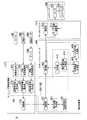
図2は、第1の実施形態の制御システム1の構成の一例を示すブロック図である。制御システム1は、例えば、カメラEM1と、力覚センサEM2と、接触センサEM3と、アンプEM4と、センシング情報処理部210と、一対以上のロボットコントローラ400およびロボットアーム装置600とを備える。 FIG. 2 is a block diagram illustrating an example of a configuration of the
カメラEM1は、例えば、ロボットアーム装置600の把持対象物(例えば、ロボットアーム装置600がピッキングする荷物)を画像認識する。カメラEM1は、把持対象物を俯瞰的に認識できる位置に配置されてもよいし、ロボットアーム装置600の把持部材周辺等の把持対象物を近距離で捉えることができる位置に配置されてもよい。カメラEM1は、認識結果(撮像データ)をセンシング情報処理部210に出力する。また、力覚センサEM2は、ロボットアーム装置600の把持部材の先端に設置され、ロボットアーム装置600が把持対象物に与える押し込み力成分およびモーメント成分を6軸で認識する。力覚センサEM2は、カメラEM1と同様に、認識結果をセンシング情報処理部210に出力する。また、接触センサEM3は、ロボットアーム装置600の把持部材の先端等に設置され、接触覚を認識する。接触センサEM3は、認識結果をアンプEM4に出力する。アンプEM4は、接触センサEM3によって出力された認識結果に基づいて把持対象物との接触認識結果を生成し、センシング情報処理部210に出力する。アンプEM4は、例えば、ローパスフィルタの機能を有する。アンプEM4は、接触センサEM3の認識結果からノイズを除去して認識結果を増幅する等の処理を行って、接触認識結果を生成する。カメラEM1、力覚センサEM2、およびアンプEM4はそれぞれ所定の時間間隔で動作する。 The camera EM1 recognizes, for example, an object to be gripped by the robot arm device 600 (eg, a load picked up by the robot arm device 600). The camera EM1 may be arranged at a position where the object to be grasped can be recognized from a bird's-eye view, or may be arranged at a position where the object to be grasped such as around the grasping member of the
センシング情報処理部210は、例えば、画像取込部212と、画像特徴量導出部214と、通信部216と、力覚信号処理部218と、力覚特徴量導出部220と、接触信号処理部222と、接触特徴量導出部224とを備える。これらの機能部は、図1に示したOSS活用プラットフォーム200上で実行される上位ソフトウェアにより実現される。画像取込部212と、力覚信号処理部218と、接触信号処理部222は、「受付部」の一例である。 The sensing
画像取込部212は、カメラEM1により出力された認識結果を取り込み、画像特徴量導出部214に出力する。画像取込部212は、カメラEM1の認識結果である撮像データの一部を選択して画像特徴量導出部214に出力してもよいし、撮像データの全てを画像特徴量導出部214に出力してもよい。画像特徴量導出部214は、画像取込部212により出力された認識結果に基づいて、画像特徴量を導出する。画像特徴量とは、カメラEM1によって撮像された撮像データから導出される把持対象物の特徴を表現する量である。画像特徴量は、例えば、把持対象物の画像上の略中心位置、色分布、輝度勾配パターン分布等を数値化あるいはベクトル化したものである。画像特徴量導出部214は、導出した画像特徴量を通信部216に出力する。 The
力覚信号処理部218は、力覚センサEM2により出力された認識結果を受け付け、その一部または全部を力覚特徴量導出部220に出力する。力覚特徴量導出部220は、力覚信号処理部218により出力された認識結果に基づいて、力覚特徴量を導出する。力覚特徴量とは、力覚センサEM2の位置および力覚センサEM2の検出する力等を数値化あるいはベクトル化したものである。力覚特徴量導出部220は、導出した力覚特徴量を通信部216に出力する。 The haptic
接触信号処理部222は、アンプEM4により出力された接触認識結果を受け付け、その一部または全部を接触特徴量導出部224に出力する。接触特徴量導出部224は、接触信号処理部222により出力された接触認識結果に基づいて、接触特徴量を導出する。接触特徴量とは、接触センサEM3によりセンシングされた認識結果を数値化したものである。接触特徴量導出部224は、導出した接触特徴量を通信部216に出力する。 The contact
通信部216は、画像特徴量導出部214により出力された画像特徴量、力覚特徴量導出部220により出力された力覚特徴量、および接触特徴量導出部224により出力された接触特徴量をロボットコントローラ400に出力する。通信部216は、画像特徴量、力覚特徴量および接触特徴量をひとまとめにしてロボットコントローラ400に出力してもよいし、それぞれの特徴量を受信する都度、ロボットコントローラ400に出力してもよい。通信部216からロボットコントローラ400への通信は、例えば、OS300を介したイーサネットや、OSS活用プラットフォーム200によって提供されるAPIで行われる。 The
ロボットコントローラ400は、例えば、通信部402と、動作指令生成部404と、目標軌道生成部406と、モータ指令値生成部408と、モータ制御演算部410とを備える。また、ロボットコントローラ400は、判定部412と、修正指令値生成部414とを備える。モータ指令値生成部408は、「指令値生成部」の一例であり、判定部412は、「制御部」の一例である。 The
通信部402は、センシング情報処理部210により送信された画像特徴量、力覚特徴量および接触特徴量を受信し、動作指令生成部404または修正指令値生成部414に出力する。動作指令生成部404は、通信部402により出力された画像特徴量、力覚特徴量および接触特徴量に基づいて、ロボットアーム装置600の動作指令を生成する。動作指令とは、例えば、ロボットアーム装置600全体で実現する動作スクリプトである。動作スクリプトには、目標点の3軸座標の情報を含む。 The
動作指令生成部404は、目標軌道生成部406に生成した動作指令を出力する。目標軌道生成部406は、動作指令生成部404により出力された動作指令に基づいて、ロボットアーム装置600の代表点(例えば、ロボットアーム装置600の先端部分や、関節部分)の目標軌道を生成する。目標軌道は、例えば、ロボットアーム装置600が通過する軌道が障害物を避ける軌道となるよう設定される。 The
目標軌道生成部406は、生成した目標軌道をモータ指令値生成部408に出力する。モータ指令値生成部408は、目標軌道生成部406により出力された目標軌道に基づいて、目標軌道に追従するように、各モータの指令値(下位の指令値の一例)をそれぞれ生成する。モータ指令値生成部408の生成する各モータの指令値は、例えば、位置または速度に関する指令を含む。モータ指令値生成部408は、生成した指令値をロボットアーム装置600に出力する。モータ指令値生成部408は、例えば、所定の間隔で指令値を出力する。 The
判定部412は、修正指令値を生成するか否かを判定する。判定部412は、例えば、動作指令生成部404が動作指令を生成した後であって、モータ指令値生成部408により生成された各モータの指令値がロボットアーム装置600に出力されていない場合に、修正指令値を生成すると判定し、修正指令値生成部414に修正指令値の生成に関する制御指令を出力する。修正指令値生成部414により生成される修正指令値は、修正方向や修正量を示す情報であってもよいし、元の情報(動作指令や目標軌道)を置換するための情報であってもよい。後者の場合、修正指令値生成部414は、動作指令の修正指令値を生成した場合、目標軌道生成部406に修正指令値を出力し、出力済の指令値を修正指令値に置換させる。また、修正指令値生成部414は、目標軌道の修正指令値を生成した場合、モータ指令値生成部408に修正指令値を出力し、出力済の指令値を修正指令値に置換させる。 The
目標軌道生成部406は、修正指令値生成部414により修正指令値が出力された場合、修正指令値に基づいて目標軌道を修正し、モータ指令値生成部408に出力する。モータ指令値生成部408は、修正された目標軌道に基づいてモータ指令値を修正し、モータ制御演算部410に出力する。モータ制御演算部410は、修正されたモータ指令値に基づいてロボットアーム装置600を制御する指令値を出力する。なお、モータ指令値生成部408に修正指令値生成部414により修正指令値を出力された場合にも、同様に修正指令値に基づいてロボットアーム装置600が制御される。モータ制御演算部410からロボットアーム装置600への通信は、例えば、OS300を介したイーサネットや、OSS活用プラットフォーム200によって提供されるAPIで行われたり、ロボットアーム装置600の製造メーカの規定する通信規格で行われたりしてもよいが、イーサキャット規格で出力することが望ましい。 When the correction command value is output from the correction command
なお、判定部412は、ロボットコントローラ400によりロボットアーム装置600に各種指令値を出力するタイミングに応じて、修正指令値の生成要否を判定する。例えば、判定部412は、動作指令生成部404が動作指令を生成していない場合には修正指令値を生成する処理を行わない。動作指令生成部404および目標軌道生成部406により生成される各種指令値と同一の指令値を出力することになるためである。 The determining
ロボットアーム装置600は、例えば、モータ602とエンコーダ604とを備える。モータ602は、ロボットコントローラ400により送信された指令値に基づいて動作する。エンコーダ604は、モータ602の位置・速度・角度等のフィードバック情報を、モータ制御演算部410に出力する。エンコーダ604は、フィードバック情報として、例えば、パルス波(A相、B相、場合によってはZ相)をパラレルに伝送する。また、エンコーダ604は、シリアル伝送方式を用いてフィードバック情報を伝送してもよい。 The
なお、図2ではモータ制御演算部410がロボットコントローラ400の構成要素である例を示したが、ロボットコントローラ400のドライバとして構成されてもよい。モータ制御演算部410がドライバとして構成される例については、図6を用いて後述する。 Although FIG. 2 illustrates an example in which the motor
ここで、比較例との比較について説明する。図3は、比較例の制御システム1Zの構成の一例を示すブロック図である。なお、以下の説明において、第1の実施形態の制御装置100で説明した内容と同様の機能を有する部分については、同様の名称および符号を付するものとし、その機能に関する具体的な説明は省略する。 Here, a comparison with the comparative example will be described. FIG. 3 is a block diagram illustrating an example of a configuration of a control system 1Z according to a comparative example. In the following description, portions having the same functions as those described in the
図3に示す制御システム1Zは、図2に示す第1の実施形態の制御システム1の判定部412および修正指令値生成部414が省略されたものである。このため、カメラEM1等の認識装置から認識結果を受信し、センシング情報処理部210によって最新の認識結果がロボットコントローラ400に送信された場合であっても、ロボットコントローラ400はすでに生成した各種指令値に最新の認識結果を反映させることはできない。 The control system 1Z shown in FIG. 3 is the same as the
これに対し、図2に示す第1の実施形態の制御システム1は、最新の認識結果に基づいて把持対象物の動きを追従し、各種指令値を修正することができる。これにより制御システム1は、従来の制御システム1Zと比較して、より高いロバスト安定性を実現することができる。また、OSS活用プラットフォーム200やOS300、外部認識装置EM1〜EM3のソフトウェア等のアップデートなどがあった場合に、そのアップデートを適用した結果、認識結果の出力様式の変更があっても、各種指令値を修正する機能への影響を最小にとどめることができる。このため、高いメンテナンス性を実現することができる。 On the other hand, the
例えば、画像取込部212は、カメラEM1の製造メーカによって提供されるソフトウェアにより実現される場合に、画像取込部212を実現するソフトウェアがアップデートされ、画像取込部212の出力様式や出力頻度が変更される可能性がある。そのような場合に、制御装置100は、画像特徴量導出部214によって画像取込部212の出力様式や出力頻度の変更に柔軟に対応し、変更に応じた特徴量導出を行ってもよい。また制御装置100は、画像特徴量導出部214によって画像取込部212の出力様式や出力頻度を変更前の様式に加工することで緩衝し、ソフトウェアのアップデート前と同様の特徴量導出を行ってもよい。これにより制御システム1は、従来の制御システム1Zと比較して、高いメンテナンス性を実現することができる。 For example, when the
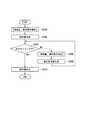
図4は、制御システム1の処理の流れの一例を示すフローチャートである。図4に示すフローチャートは、例えば、ロボットコントローラ400によってロボットアーム装置600に指令値が出力される所定の時間間隔と同一、またはその時間間隔よりも短い時間間隔を周期として繰り返し実行される。 FIG. 4 is a flowchart illustrating an example of a processing flow of the
センシング情報処理部210は、外部認識装置により出力された認識結果に基づいて、特徴量を導出する(ステップS100)。詳細は図5を用いて後述する。次に、ロボットコントローラ400は、前述した各種指令値を生成する(ステップS102)。次に、判定部412は、ロボットアーム装置600に指令値を出力するタイミングであるか否かを判定する(ステップS104)。ロボットコントローラ400は、出力するタイミングであると判定された場合、生成済の指令値をロボットアーム装置600に出力する(ステップS106)。 The sensing
ステップS104において出力するタイミングでないと判定された場合、ロボットコントローラ400は、修正指令値生成部414による修正指令値の生成のため、新たな認識結果に基づく各種特徴量を受け付ける(ステップS108)。次に、修正指令値生成部414は、修正指令値を生成して目標軌道生成部406および/またはモータ指令値生成部408に出力して出力済の指令値と置換させ(ステップS110)、ステップS104に処理を戻す。以上、本フローチャートの処理を終了する。 If it is determined in step S104 that it is not the timing to output, the
図5は、図4のフローチャートのステップS100およびS108の特徴量導出処理の流れの一例を示すフローチャートである。なお、以下に示すステップS200、S204およびS208は同時に行われてもよいし、それぞれ独立したタイミングで行われてもよい。 FIG. 5 is a flowchart showing an example of the flow of the feature amount deriving process in steps S100 and S108 of the flowchart in FIG. Steps S200, S204, and S208 described below may be performed simultaneously, or may be performed at independent timings.
画像取込部212は、カメラEM1によって出力された撮像データを受信し、画像特徴量導出部214に出力する(ステップS200)。次に、画像特徴量導出部214は、画像取込部212により出力された撮像データに基づいて画像特徴量を導出して通信部216を介してロボットコントローラ400に出力する(ステップS202)。 The
力覚信号処理部218は、力覚センサEM2によって出力された認識結果を受信し、力覚特徴量導出部220に出力する(ステップS204)。次に、力覚特徴量導出部220は、力覚信号処理部218によって出力された認識結果に基づいて力覚特徴量を導出して通信部216を介してロボットコントローラ400に出力する(ステップS206)。 The haptic
接触信号処理部222は、アンプEM4によって出力された接触認識結果を受信し、接触特徴量導出部224に出力する(ステップS208)。次に、接触特徴量導出部224は、接触信号処理部222によって出力された認識結果に基づいて接触特徴量を導出して通信部216を介してロボットコントローラ400に出力する(ステップS210)。以上、本フローチャートの処理を終了する。 The contact
以上説明した第1の実施形態の制御システム1によれば、センシング情報処理部210がカメラEM1等の認識装置から認識結果を受信した場合に、判定部412によって修正指令値の生成が可能であるか否かが判定され、判定部412の判定結果に基づいて修正指令値生成部414によって修正指令値が生成されることで、ロボットアーム装置600に最新の認識結果に基づく修正指令値を出力することができるため、より高いロバスト安定性およびメンテナンス性を実現することができる。 According to the
(第2の実施形態)
次に、第2の実施形態の制御システム1Aについて説明する。以下の説明において、第1の実施形態で説明した内容と同様の機能を有する部分については、同様の名称および符号を付するものとし、その機能に関する説明は省略する。後述する他の実施形態についても同様とする。(Second embodiment)
Next, a control system 1A according to a second embodiment will be described. In the following description, portions having the same functions as those described in the first embodiment will be given the same names and reference numerals, and descriptions of the functions will be omitted. The same applies to other embodiments described later.
図6は、第2の実施形態の制御システム1Aの構成の一例を示すブロック図である。図6の制御システム1Aは、図2の制御システム1と比較して、動作計画部150を更に備え、動作指令生成部404が削除され、モータ制御演算部410がサーボドライバ510に置換されている点が異なる。したがって、以下では動作計画部150とサーボドライバ510の説明を中心に行う。動作計画部150は、例えば、図1に示したOSS活用プラットフォーム200またはOS300で実行される中位ソフトウェアにより実現される。 FIG. 6 is a block diagram illustrating an example of a configuration of a control system 1A according to the second embodiment. The control system 1A of FIG. 6 further includes an
動作計画部150は、例えば、通信部152と、動作計画生成部154と、動作学習部156とを備える。通信部152は、センシング情報処理部210の通信部216により送信された画像特徴量、力覚特徴量、および接触特徴量を受信し、動作計画生成部154に出力する。動作計画生成部154は、通信部152により出力された各種特徴量に基づいて、動作計画を生成する。動作計画とは、ロボットアーム装置600に行わせる1以上の動作指令である。動作計画生成部154は、例えば、図2の動作指令生成部404と同様に、動作スクリプトを生成する。動作計画生成部154は、生成した動作計画を動作学習部156および通信部152に出力する。通信部152は、動作計画生成部154により出力された動作計画を、ロボットコントローラ400に送信する。通信部152からロボットコントローラ400への通信は、例えば、OS300を介したイーサネットや、OSS活用プラットフォーム200によって提供されるAPIで行われる。 The
動作学習部156は、動作計画生成部154により出力された動作計画の一部または全部を記憶学習する。動作学習部156は、動作計画の一部を記憶学習する場合、例えば、カメラEM1によって把持対象物と障害物との配置をパターン化して学習することで、ロボットアーム装置600の軌道に関する動作計画の決定規則を生成する。動作計画生成部154は、認識結果が決定規則に当てはまるか否かを判定し、当てはまる場合には決定規則に基づいて動作計画を生成する。動作計画生成部154は、認識結果が決定規則に当てはまらない場合には動作計画を生成し、その認識結果および動作計画を動作学習部156に記憶させる。また、動作学習部156の記憶する決定規則は、把持対象物と障害物との位置情報に基づくロボットアーム装置600の軌道に関する規則に限らず、例えば、把持対象物の輪郭線から把持部材の把持位置を決定する決定規則であってもよい。 The
また、動作学習部156は、例えば、制御システム1Aの利用者によってあらかじめ設定された正常な動作計画を表す動作計画を教師データとして、動作計画生成部154により出力された動作計画と基準学習データとの乖離度合を導出し、導出した乖離度合を動作計画生成部154に出力する。動作計画生成部154は、動作学習部156によって出力された乖離度合に基づいて、生成する動作計画の位置精度の補填を行う。 Further, the
ロボットコントローラ400のモータ指令値生成部408は、生成したモータ指令値を通信部402に出力する。通信部402は、モータ指令値生成部408により出力されたモータ指令値を、サーボドライバ510に出力する。通信部402からサーボドライバ510への通信は、例えば、OS300を介したイーサネットや、OSS活用プラットフォーム200によって提供されるAPIで行われたり、ロボットアーム装置600の製造メーカの規定する通信規格で行われたりしてもよいが、イーサキャット規格で出力することが望ましい。 The motor command
サーボドライバ510の通信部512は、通信部402により出力されたモータ指令値をモータ制御演算部514に出力する。モータ制御演算部514は、通信部512により出力されたモータ指令値に基づいて、ロボットアーム装置600を制御する指令値を演算し、演算した指令値をロボットアーム装置600に出力する。通信部512は、ロボットアーム装置600に専用の動力信号(モータ602の駆動を制御するモータ駆動電流)を送信する。 The
なお、動作計画部150は、図1の制御装置100上で実行される。動作計画部150は、センシング情報処理部210の画像特徴量導出部214、力覚特徴量導出部220、および接触特徴量導出部224が実現されるプロセッサと同一のプロセッサ上で実現されてもよいし、ロボットコントローラ400の判定部412および修正指令値生成部414が実現されるプロセッサと同一のプロセッサ上で実現されてもよい。 The
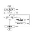
図7は、制御システム1Aの処理の流れの一例を示すフローチャートである。ステップS304の処理は、図4のフローチャートにおけるステップS104の処理と同様である。また、ステップS310の処理は、図4のフローチャートにおけるステップS106の処理と同様である。したがって、下記ではステップS300〜S302、およびS306〜S308について説明する。 FIG. 7 is a flowchart illustrating an example of a processing flow of the control system 1A. The process of step S304 is the same as the process of step S104 in the flowchart of FIG. Further, the processing of step S310 is the same as the processing of step S106 in the flowchart of FIG. Therefore, steps S300 to S302 and S306 to S308 will be described below.
動作計画部150は、センシング情報処理部210により送信された各種特徴量に基づいて動作計画を生成する(ステップS300)。詳細は図8を用いて後述する。次に、ロボットコントローラ400は、動作計画に基づいて指令値を生成する(ステップS302)。 The
ステップS304において出力するタイミングでないと判定された場合、ロボットコントローラ400は、修正指令値生成部414による修正指令値の生成のため、新たな認識結果に基づく各種特徴量を受け付ける(ステップS306)。次に、修正指令値生成部414は、修正指令値を生成して目標軌道生成部406またはモータ指令値生成部408に出力して出力済の指令値と置換させ(ステップS308)、ステップS304に処理を戻す。以上、本フローチャートの処理を終了する。 If it is determined in step S304 that it is not the timing to output, the
図8は、制御システム1Aにおける特徴量導出処理、および動作計画学習処理の流れの一例を示すフローチャートである。ステップS400〜410の処理は、図4のフローチャートにおけるステップS200〜210の処理と同様である。また、図8のフローチャートは、図5と比較してステップS412〜S418が追加される点が異なる。したがって、下記ではステップS412〜S418について説明する。 FIG. 8 is a flowchart illustrating an example of the flow of the feature amount derivation process and the operation plan learning process in the control system 1A. The processing of steps S400 to S410 is the same as the processing of steps S200 to S210 in the flowchart of FIG. 8 is different from FIG. 5 in that steps S412 to S418 are added. Therefore, steps S412 to S418 will be described below.
ステップS202、S206およびS210の処理の後、動作計画生成部154は、各種特徴量が決定規則に当てはまるか否かを判定する(ステップS412)。動作計画生成部154は、決定規則に当てはまると判定した場合、通信部152により出力された各種特徴量におよび決定規則に基づいて動作計画を生成する(ステップS414)。動作計画生成部154は、決定規則に当てはまらないと判定した場合、通信部152により出力された各種特徴量に基づいて、動作計画および規則を生成する(ステップS416)。次に、動作計画を学習する(ステップS418)。以上、本フローチャートの処理を終了する。 After the processing of steps S202, S206, and S210, the operation
以上説明した第2の実施形態の制御システム1Aによれば、第1の実施形態と同様の効果を奏する他、各種特徴量から導出される決定規則を動作学習部156が記憶し、動作学習部156によって記憶された動作計画の決定規則に基づいて動作計画生成部154が動作計画を生成することで、修正指令値の生成精度を向上させることができる。 According to the control system 1A of the second embodiment described above, in addition to the same effects as in the first embodiment, the
(第3の実施形態)
次に、第3の実施形態の制御システム1Bについて説明する。(Third embodiment)
Next, a control system 1B according to a third embodiment will be described.
図9は、第3の実施形態の制御システム1Bの構成の一例を示すブロック図である。図9の制御システム1Bは、図6の制御システム1Aと比較して、距離センサEM7、光学センサEM8、センシング情報処理部210Bの構成要素、動作計画部150Bの構成要素が異なる。したがって、以下では、制御システム1Aとの相違点を中心に説明する。なお、3次元点群生成部230、特徴量導出部232および最適化計算部234は、図1に示したOSS活用プラットフォーム200上で実行される上位ソフトウェアにより実現される。 FIG. 9 is a block diagram illustrating an example of a configuration of a control system 1B according to the third embodiment. The control system 1B of FIG. 9 differs from the control system 1A of FIG. 6 in the distance sensor EM7, the optical sensor EM8, the components of the sensing
距離センサEM7は、例えば、ロボットアーム装置600の把持部材の先端等に設置され、カメラEM1の認識した把持対象物とロボットアーム装置600の把持部材との測定タイミングでの距離を測定する。距離センサEM7は、測定結果を距離信号処理部226に送信する。光学センサEM8は、例えば、カメラEM1が可視光線を収集して撮像データを生成する場合、カメラEM1とは異なる光線(例えば、近赤外線、短波長赤外線、熱赤外線等)で撮像データを生成する。カメラEM1および光学センサEM8は、両者ともに把持対象物を認識するのに用いられてもよいし、カメラEM1にはロボットアーム装置600が把持する把持対象物を認識させ、光学センサEM8には把持対象物以外の障害物を認識させるというように用途が分けられてもよい。また、光学センサEM8に把持対象物を認識させる場合、光学センサEM8はカメラEM1とは異なる箇所に設置されることで、カメラEM1および光学センサEM8の認識結果から把持対象物の3次元計測結果を導出することができる。光学センサEM8は、アンプEM4を介して認識結果を光学信号処理部228に送信する。 The distance sensor EM7 is installed, for example, at the tip of the gripping member of the
センシング情報処理部210Bは、図2および図6のセンシング情報処理部210と比較して、力覚信号処理部218および接触信号処理部222が、距離信号処理部226および光学信号処理部228に置き換わっている点が異なる。また、センシング情報処理部210Bは、図2のセンシング情報処理部210と比較して、3次元点群生成部230と、特徴量導出部232と、最適化計算部234とをさらに備える点が異なる。3次元点群生成部230、特徴量導出部232、および最適化計算部234は、「上位ソフトウェア」の他の一例であり、動作計画部150Bは、「中位ソフトウェア」および「下位ソフトウェア」の他の一例である。 The sensing
距離信号処理部226は、距離センサEM7により送信された測定結果に基づいて、把持対象物とロボットアーム装置600の把持部材との距離を導出し、3次元点群生成部230に出力する。光学信号処理部228は、アンプEM4により出力された光学センサEM8の把持対象物または障害物の認識結果の一部または全部を3次元点群生成部230に出力する。 The distance
3次元点群生成部230は、画像取込部212により出力された認識結果、距離信号処理部226により出力された測定結果、および光学信号処理部228により出力された認識結果に基づいて、ロボットアーム装置600の移動可能な経路を示す3次元点群データを生成する。3次元点群生成部230は、生成した3次元点群データを、特徴量導出部232に出力する。 The three-dimensional point
特徴量導出部232は、3次元点群生成部230により出力された3次元点群データを分析し、把持対象物の大きさ、面積、位置、略中心などの情報を示す3次元特徴量を導出する。特徴量導出部232は、導出した3次元特徴量を、通信部216を介して動作計画部150Bに送信する。また、特徴量導出部232は、導出した3次元特徴量を最適化計算部234に出力する。 The feature
特徴量導出部232は、単一の特徴量導出方法を用いて3次元特徴量を導出してもよいし、複数の特徴量導出方法を用いて3次元特徴量を導出した結果を比較することで、ノイズ除去したり、3次元特徴量の導出精度を自ら評価したりすることで、最も精度が高いと判定した3次元特徴量の導出結果を最適化計算部234に出力してもよい。 The feature
最適化計算部234は、特徴量導出部232によって出力された3次元特徴量を記憶し、3次元特徴量の導出に用いるパラメータ等を調整する。最適化計算部234は、3次元点群生成部230により出力された3次元点群データの一部または全部を併せて記憶してもよい。 The
3次元点群生成部230、特徴量導出部232および最適化計算部234は、図1の制御装置100上で実行される。 The three-dimensional point
動作計画部150Bは、図6の動作計画部150と比較して、把持計画生成部158と、障害物検出部160と、把持計画学習部162とを備える点が異なる。 The
把持計画生成部158は、通信部152を介してセンシング情報処理部210Bから受信した3次元特徴量に基づいて、把持対象物の把持計画を生成する。把持計画は、例えば、ロボットアーム装置600が把持対象物を把持する位置や把持する力、ロボットアーム装置600自身の把持姿勢の計画を含む。把持計画生成部158は、生成した把持計画を動作計画生成部154および把持計画学習部162に出力する。 The grip
障害物検出部160は、通信部152を介してセンシング情報処理部210Bから受信した3次元特徴量に基づいて、障害物を検出し、検出した障害物の位置情報を生成する。障害物検出部160は、生成した障害物の位置情報を動作計画生成部154に出力する。 The
動作計画生成部154は、把持計画生成部158により出力された把持計画と、障害物検出部160により出力された障害物の位置情報とに基づいて、ロボットアーム装置600の動作計画を生成する。動作計画生成部154は、生成した動作計画を、通信部152を介してロボットコントローラ400に送信する。 The motion
把持計画学習部162は、動作計画生成部154により出力された動作計画の一部または全部を記憶学習する。把持計画学習部162は、例えば、ロボットアーム装置600の把持対象物の形状等が類似する場合、動作計画のうち、把持計画生成部158により出力された把持計画だけを抽出して記憶学習してもよい。また、把持計画学習部162は、例えば、障害物の位置が殆ど変化しない場合、障害物検出部160により出力された障害物の位置情報だけを抽出して記憶学習してもよい。把持計画学習部162は、例えば、把持対象物と障害物との配置等をパターン化して学習することで、ロボットアーム装置600の軌道に関する把持計画の決定規則を生成する。把持計画学習部162は、動作計画生成部154に動作計画を生成する際の決定規則を出力する。動作計画生成部154は、把持計画学習部162により出力された決定規則のパターンに当てはまる場合、決定規則に基づいて動作計画を生成する。また、把持計画学習部162は、把持計画生成部158に把持計画を生成する際の決定規則を出力する。把持計画生成部158は、把持計画学習部162により出力された決定規則のパターンに当てはまる場合、決定規則に基づいて把持計画を生成する。 The grip
なお、動作計画部150Bは、図1の制御装置100上で実行される。動作計画部150Bは、例えば、3次元点群生成部230、特徴量導出部232および最適化計算部234が実現されるプロセッサと異なる他のプロセッサ上で実現される。 The
図10は、制御システム1Bの処理の流れの一例を示すフローチャートである。ステップS500〜S506の処理は、図7のフローチャートにおけるステップS300〜S306の処理と同様である。また、ステップS510の処理は、図7のフローチャートにおけるステップS310の処理と同様である。図10に示すフローチャートは、図7のフローチャートと比較して、ステップS500およびS508に示す処理セットが異なる。したがって、下記ではステップS500およびS508の処理セットについて図11のフローチャートを用いて説明する。 FIG. 10 is a flowchart illustrating an example of a processing flow of the control system 1B. The processing of steps S500 to S506 is the same as the processing of steps S300 to S306 in the flowchart of FIG. Further, the processing of step S510 is the same as the processing of step S310 in the flowchart of FIG. The flowchart shown in FIG. 10 differs from the flowchart of FIG. 7 in the processing set shown in steps S500 and S508. Therefore, the processing sets of steps S500 and S508 will be described below with reference to the flowchart of FIG.
図11は、制御システム1Bにおける特徴量導出処理、および動作計画学習処理の流れの一例を示すフローチャートである。ステップS600の処理は、図8のフローチャートにおけるステップS400の処理と同様である。また、ステップS608の処理は、図5のフローチャートにおけるステップS412の処理と同様である。また、ステップS618の処理は、図5のフローチャートにおけるステップS414の処理と同様である。図11のフローチャートは、図8と比較してステップS602〜S606、およびステップS610〜S616が追加される点が異なる。したがって、下記ではステップS602〜S606、およびステップS610〜S616を中心に説明する。なお、以下に示すステップS600、S602およびS604は同時に行われてもよいし、それぞれ独立したタイミングで行われてもよい。 FIG. 11 is a flowchart illustrating an example of the flow of the feature amount derivation process and the operation plan learning process in the control system 1B. The process in step S600 is the same as the process in step S400 in the flowchart in FIG. Further, the processing in step S608 is the same as the processing in step S412 in the flowchart in FIG. The processing in step S618 is the same as the processing in step S414 in the flowchart in FIG. 11 is different from FIG. 8 in that steps S602 to S606 and steps S610 to S616 are added. Therefore, the following mainly describes steps S602 to S606 and steps S610 to S616. Steps S600, S602, and S604 described below may be performed simultaneously, or may be performed at independent timings.
距離信号処理部226は、距離センサEM7により送信された測定結果に基づいて、把持対象物とロボットアーム装置600の把持部材との距離を導出し、3次元点群生成部230に出力する(ステップS602)。また、光学信号処理部228は、光学センサEM8の把持対象物または障害物の認識結果を3次元点群生成部230に出力する(ステップS604)。ステップS600、S602およびS604の処理の後、3次元点群生成部230は、ロボットアーム装置600の移動可能な経路を示す3次元点群データを生成する(ステップS606)。 The distance
ステップS608において決定規則に当てはまると判定された場合、把持計画生成部158は決定規則に基づいて把持計画を生成する(ステップS610)。また、ステップS400において決定規則に当てはまらないと判定された場合、把持計画生成部158は把持計画を生成し(ステップS612)、把持計画学習部162に生成した把持計画を学習させる(ステップS614)。また、ステップS604の処理の後、障害物検出部160は、障害物を検出する(ステップS616)。 If it is determined in step S608 that the determination rule is satisfied, the grip
ステップS610,S614およびS616の処理の後、動作計画生成部154は、ステップS618の処理を行う。以上、本フローチャートの処理を終了する。 After the processing in steps S610, S614, and S616, the operation
以上説明した第3の実施形態の制御システム1Bによれば、第1の実施形態および第2の実施形態と同様の効果を奏する他、障害物検出部160が障害物を検出し、3次元特徴量から導出される把持計画の決定規則を把持計画学習部162が記憶し、障害物検出部160の障害物検出結果、および把持計画学習部162によって記憶された把持計画の決定規則に基づいて動作計画生成部154が動作計画を生成することで、把持計画および動作計画の生成精度や生成性能をより向上させることができる。 According to the control system 1B of the third embodiment described above, the same effects as those of the first embodiment and the second embodiment can be obtained, and the
(第4の実施形態)
次に、第4の実施形態の制御システム1Cについて説明する。(Fourth embodiment)
Next, a
図12は、第4の実施形態の制御システム1Cの構成の一例を示すブロック図である。図12に示す構成は、図6に示した制御システム1Aの構成と比較して、ログ記憶部800をさらに備える点が異なる。ログ記憶部800は、図1に示したOSS活用プラットフォーム200で実行される上位ソフトウェアにより実現される。したがって、以下ではログ記憶部800を中心に説明する。 FIG. 12 is a block diagram illustrating an example of a configuration of a
ログ記憶部800は、例えば、通信部802と、記憶部804と、分析部806とを備える。通信部802は、制御システム1Cのセンシング情報処理部210のログ対象情報処理部236、動作計画部150のログ対象情報処理部164、およびロボットコントローラ400のログ対象情報処理部416から出力されるログ情報を受信する。通信部802は受信したログ情報を記憶部804に記憶させる。ログ記憶部800は、例えば、制御装置100の上位ソフトウェアが実行されることによって実現される。ログ対象情報処理部236、ログ対象情報処理部164、およびログ対象情報処理部416は、「ログ処理部」の一例である。 The
分析部806は、所定の間隔(例えば、数時間〜1日に1度)で記憶部804に記憶されたログ情報を分析し、所定の傾向が見られるか否かを判定する。所定の傾向とは、例えば、消耗部品の劣化の傾向や、部品故障の傾向である。分析部806は、所定の傾向が見られると判定した場合、制御システム1Cの表示装置に判定結果を表示させてもよいし、あらかじめ設定された方法(例えば、メール等)で制御システム1Cの管理者に判定結果を通知してもよい。 The
センシング情報処理部210のログ対象情報処理部236、動作計画部150のログ対象情報処理部164、およびロボットコントローラ400のログ対象情報処理部416から出力されるログ情報は、例えば、どの装置から、どのタイミングで、どういうログ種別のログとして出力されたログ情報であるかの情報を含む。 The log information output from the log information processing unit 236 of the sensing
また、ログ情報は、ログの緊急度や用途レベルに応じて出力レベルが設定可能であり、制御システム1Cの管理者によって最低限のログのみ出力する、収集できる全てのログ情報を出力する等の出力レベルの設定が可変である。例えば、センシング情報処理部210のログ対象情報処理部236は、画像取込部212および画像特徴量導出部214から処理ログの一部または全部を出力される。ログ対象情報処理部236は、処理ログ情報から所定の傾向の分析に用いる情報に関する部分を加工抽出して、通信部216に出力する。同様に、ログ対象情報処理部236は、力覚信号処理部218、力覚特徴量導出部220、接触信号処理部222、および接触特徴量導出部224から処理ログの一部または全部を出力され、処理ログ情報から所定の傾向の分析に用いる情報に関する部分を加工抽出して、通信部216に出力する。通信部216は、ログ記憶部800の通信部802に加工抽出したログ情報を送信する。 The output level of the log information can be set in accordance with the urgency or the usage level of the log. The administrator of the
動作計画部150のログ対象情報処理部164は、ログ対象情報処理部236と同様に、動作計画生成部154および動作学習部156から処理ログの一部または全部を出力される。ログ対象情報処理部164は、処理ログ情報から所定の傾向の分析に用いる情報に関する部分を加工抽出して、通信部152に出力する。通信部152は、ログ記憶部800の通信部802に加工抽出したログ情報を送信する。 The log target
また、ロボットコントローラ400のログ対象情報処理部416は、目標軌道生成部406、モータ指令値生成部408、判定部412、および修正指令値生成部414から処理ログの一部または全部を出力される。ログ対象情報処理部416は、処理ログ情報から所定の傾向の分析に用いる情報に関する部分を加工抽出して、通信部402に出力する。通信部402は、ログ記憶部800の通信部802に加工抽出したログ情報を送信する。 The log target
図13は、制御システム1Cのログ記憶部800のログ収集処理の流れの一例を示すフローチャートである。 FIG. 13 is a flowchart illustrating an example of the flow of a log collection process of the
まず、通信部802は、センシング情報処理部210のログ対象情報処理部236、動作計画部150のログ対象情報処理部164、およびロボットコントローラ400のログ対象情報処理部416から出力されるログ情報を受信し、記憶部804に記憶させる(ステップS700)。次に、分析部806は、記憶部804に記憶されたログ情報を分析する(ステップS702)。分析部806は、記憶部804に記憶されたログ情報を分析した結果、所定の傾向が見られるか否かを判定する(ステップS704)。分析部806は、所定の傾向が見られると判定した場合、制御システム1Cの管理者に通知し(ステップS706)、処理を終了する。分析部806は、所定の傾向が見られると判定しなかった場合、本フローチャートの処理を終了する。 First, the
以上説明した第4の実施形態の制御システム1Cによれば、第1の実施形態、第2の実施形態、第3の実施形態と同様の効果を奏する他、記憶部804の記憶する制御システム1Cのログ情報を分析部806が分析し、所定の傾向が見られるか否かを判定することで消耗部品の劣化や故障の傾向等を検知することによって、さらに高いメンテナンス性を実現することができる。 According to the
上述の説明において、制御装置100の制御対象がロボットアーム装置600である例を用いて説明したが、制御装置100の制御対象は他の自律動作機構、例えば移動体(自律走行する移動体や、自律飛行する移動体等)であってもよい。 In the above description, an example in which the control target of the
以上説明した少なくともひとつの実施形態によれば、2以上のプロセッサを備え、カメラEM1等の認識装置から受信する認識結果に基づいて、ロボットアーム装置600のような自律動作機構を制御するロボットコントローラ400を制御する制御装置100を実現する第1のプロセッサおよび第2のプロセッサのうち、第1のプロセッサにおいてセンシング情報処理部210によって実現されるカメラEM1等の認識結果の特徴を表す特徴量を導出する上位ソフトウェアを実現し、第2のプロセッサにおいてロボットコントローラ400が動作計画に基づいてロボットアーム装置600を制御する指令値を出力する下位ソフトウェアを実現し、第1のプロセッサまたは第2のプロセッサのいずれかでセンシング情報処理部210によって導出された特徴量に基づいて、動作計画を生成する中位ソフトウェアを実現することにより、より高いロバスト安定性およびメンテナンス性を実現することができる。 According to at least one embodiment described above, the
本発明のいくつかの実施形態を説明したが、これらの実施形態は、例として提示したものであり、発明の範囲を限定することは意図していない。これら実施形態は、その他の様々な形態で実施されることが可能であり、発明の要旨を逸脱しない範囲で、種々の省略、置き換え、変更を行うことができる。これら実施形態やその変形は、発明の範囲や要旨に含まれると同様に、特許請求の範囲に記載された発明とその均等の範囲に含まれるものである。 Although several embodiments of the present invention have been described, these embodiments are provided by way of example and are not intended to limit the scope of the invention. These embodiments can be implemented in other various forms, and various omissions, replacements, and changes can be made without departing from the spirit of the invention. These embodiments and their modifications are included in the scope and gist of the invention, and are also included in the invention described in the claims and equivalents thereof.
1、1A、1B、1C、1Z…制御システム、100…制御装置、150…動作計画部、150B…動作計画部、152…通信部、154…動作計画生成部、156…動作学習部、158…把持計画生成部、160…障害物検出部、162…把持計画学習部、164…ログ対象情報処理部、200…OSS活用プラットフォーム、210、210B…センシング情報処理部、212…画像取込部、214…画像特徴量導出部、216…通信部、218…力覚信号処理部、220…力覚特徴量導出部、222…接触信号処理部、224…接触特徴量導出部、226…距離信号処理部、228…光学信号処理部、230…次元点群生成部、232…特徴量導出部、234…最適化計算部、236…ログ対象情報処理部、300…OS、400…ロボットコントローラ、402…通信部、404…動作指令生成部、406…目標軌道生成部、408…モータ指令値生成部、410…モータ制御演算部、412…判定部、414…修正指令値生成部、416…ログ対象情報処理部、500…サーボアンプ、510…サーボドライバ、512…通信部、514…モータ制御演算部、600…ロボットアーム装置、602…モータ、604…エンコーダ、800…ログ記憶部、802…通信部、804…記憶部、806…分析部 1, 1A, 1B, 1C, 1Z: control system, 100: control device, 150: operation planning unit, 150B: operation planning unit, 152: communication unit, 154: operation plan generation unit, 156: operation learning unit, 158 ... Gripping plan generating unit, 160: Obstacle detecting unit, 162: Gripping plan learning unit, 164: Log target information processing unit, 200: OSS utilization platform, 210, 210B: Sensing information processing unit, 212: Image capturing unit, 214 ... Image feature derivation unit, 216 communicator, 218 haptic signal processing unit, 220 haptic feature derivation unit, 222 contact signal processing unit, 224 contact feature derivation unit, 226 distance
Claims (10)
Translated fromJapanese前記認識結果の特徴を表す特徴量を導出する上位ソフトウェアと、
前記特徴量に基づいて、前記自律動作機構の動作計画を生成する中位ソフトウェアと、
前記動作計画に基づいて前記自律動作機構を制御する指令値を出力する下位ソフトウェアと、を記憶装置に格納し、
前記第1のプロセッサは、
少なくとも前記上位ソフトウェアを実行し、
前記第2のプロセッサは、
少なくとも前記下位ソフトウェアを実行し、
前記制御装置が備える少なくとも一つのプロセッサは、
前記中位ソフトウェアを実行する、
制御装置。A control device comprising at least two processors including at least a first processor and a second processor, and controlling one or more autonomous operation mechanisms based on a recognition result received from the recognition device,
Higher-level software for deriving a feature amount representing a feature of the recognition result,
Based on the feature amount, intermediate software generating an operation plan of the autonomous operation mechanism,
And lower-level software that outputs a command value for controlling the autonomous operation mechanism based on the operation plan, stored in a storage device,
The first processor comprises:
At least execute the upper software,
The second processor comprises:
Executing at least the lower-level software,
At least one processor included in the control device,
Executing the intermediate software,
Control device.
請求項1に記載の制御装置。Controlling a robot controller that controls the autonomous operation mechanism,
The control device according to claim 1.
前記動作計画に基づいて、前記自律動作機構を制御する下位の指令値を出力する指令値生成部と、
前記ロボットコントローラが前記認識結果に基づいて前記動作計画を作成した後、前記認識装置から新たに認識結果を受信した場合に、前記指令値生成部に、前記指令値とは異なる修正指令値を生成させるか否かを判定し、判定結果に基づいて制御する制御部と、
前記制御部による制御指令に基づいて、前記修正指令値を生成する修正指令値生成部と、として機能させる、
請求項2記載の制御装置。The lower-level software controls the second processor,
A command value generation unit that outputs a lower-order command value that controls the autonomous operation mechanism based on the operation plan,
After the robot controller creates the operation plan based on the recognition result, when a new recognition result is received from the recognition device, the command value generation unit generates a correction command value different from the command value. A control unit that determines whether or not to perform the control based on the determination result,
Based on a control command from the control unit, a correction command value generation unit that generates the correction command value,
The control device according to claim 2.
前記認識結果を受け付ける受付部と、
前記認識結果に基づいて、前記認識結果の特徴量を導出する特徴量導出部と、として機能させ、
前記中位ソフトウェアは、前記少なくとも一つのプロセッサを、
前記特徴量に基づいて前記自律動作機構の動作計画を生成する動作計画部として機能させる、
請求項3記載の制御装置。The higher-level software controls the first processor,
A receiving unit that receives the recognition result,
Based on the recognition result, and a feature amount deriving unit that derives a feature amount of the recognition result,
The intermediate software, the at least one processor,
Functioning as an operation planning unit that generates an operation plan of the autonomous operation mechanism based on the feature amount,
The control device according to claim 3.
前記認識結果および前記動作計画の一部または全部を記憶して学習する動作学習部と、としてさらに機能させる、
請求項4に記載の制御装置。The intermediate software, at least one processor provided in the control device,
An operation learning unit that stores and learns part or all of the recognition result and the operation plan, and further functions as
The control device according to claim 4.
前記中位ソフトウェアは、前記制御装置が備える少なくとも一つのプロセッサを、
前記認識結果に基づいて、前記自律動作機構に行わせる前記把持部材に行わせる把持動作の計画を生成する把持計画生成部と、
前記把持計画生成部によって生成された前記把持動作の計画を記憶し、学習する把持計画学習部と、としてさらに機能させる、
請求項4または5に記載の制御装置。When the autonomous operation mechanism includes a gripping member,
The intermediate software, at least one processor provided in the control device,
Based on the recognition result, a grip plan generation unit that generates a plan of a grip operation performed by the grip member to be performed by the autonomous operation mechanism,
The plan of the grip operation generated by the grip plan generation unit is stored, and further functions as a grip plan learning unit that learns.
The control device according to claim 4.
前記上位ソフトウェアが実行されることで、
少なくとも前記ロボットコントローラの処理結果、および前記修正指令値生成部の生成する前記修正指令値の生成結果の記録を出力するログ処理部と、
前記ログ処理部によって出力された前記記録を記憶するログ記憶部と、としてさらに機能させる、
請求項4から6のいずれか1項に記載の制御装置。The higher-level software controls the first processor,
By executing the upper software,
A log processing unit that outputs at least a processing result of the robot controller and a record of a generation result of the correction command value generated by the correction command value generation unit;
And a log storage unit that stores the record output by the log processing unit,
The control device according to claim 4.
前記特徴量導出部によって、前記認識装置から受信する前記認識結果の出力様式の変更を緩衝する、ように機能させる、
請求項4から7のいずれか1項に記載の制御装置。The higher-level software controls the first processor,
By the feature amount derivation unit, to function to buffer changes in the output format of the recognition result received from the recognition device,
The control device according to claim 4.
前記第1のプロセッサが、前記上位ソフトウェアを実行することにより、前記認識結果の特徴を表す特徴量を導出し、
前記制御装置が備える少なくとも一つのプロセッサが、前記中位ソフトウェアを実行することにより、前記特徴量に基づいて、前記自律動作機構の動作計画を生成し、
前記第2のプロセッサが、前記下位ソフトウェアを実行することにより、前記動作計画に基づいて前記自律動作機構を制御する指令値を出力する、
制御方法。A control device comprising at least two processors including at least a first processor and a second processor, and controlling one or more autonomous operation mechanisms based on a recognition result received from the recognition device, comprising a host software, And a control method of the autonomous operation mechanism by a control device that stores lower software and lower software in a storage device,
The first processor derives a feature amount representing a feature of the recognition result by executing the higher-level software,
At least one processor included in the control device executes the intermediate software to generate an operation plan of the autonomous operation mechanism based on the feature amount,
The second processor, by executing the lower software, outputs a command value for controlling the autonomous operation mechanism based on the operation plan,
Control method.
前記第1のプロセッサにより実行され、前記認識結果の特徴を表す特徴量を導出する上位プログラムと、
前記制御装置が備える少なくとも一つのプロセッサにより実行され、前記特徴量に基づいて、前記自律動作機構の動作計画を生成する中位プログラムと、
前記第2のプロセッサにより実行され、前記動作計画に基づいて前記自律動作機構を制御する指令値を出力する下位プログラムと、を含む、
プログラム。A program executed by a control device that includes at least two processors including at least a first processor and a second processor, and that controls one or more autonomous operation mechanisms based on a recognition result received from the recognition device,
An upper-level program executed by the first processor to derive a feature amount representing a feature of the recognition result;
A middle-level program that is executed by at least one processor included in the control device and generates an operation plan of the autonomous operation mechanism based on the feature amount,
A lower-level program that is executed by the second processor and outputs a command value that controls the autonomous operation mechanism based on the operation plan.
program.
Priority Applications (2)
| Application Number | Priority Date | Filing Date | Title |
|---|---|---|---|
| JP2018150220AJP2020025992A (en) | 2018-08-09 | 2018-08-09 | Control device, control method, and program |
| US16/285,263US11318612B2 (en) | 2018-08-09 | 2019-02-26 | Control device, control method, and storage medium |
Applications Claiming Priority (1)
| Application Number | Priority Date | Filing Date | Title |
|---|---|---|---|
| JP2018150220AJP2020025992A (en) | 2018-08-09 | 2018-08-09 | Control device, control method, and program |
Publications (1)
| Publication Number | Publication Date |
|---|---|
| JP2020025992Atrue JP2020025992A (en) | 2020-02-20 |
Family
ID=69584145
Family Applications (1)
| Application Number | Title | Priority Date | Filing Date |
|---|---|---|---|
| JP2018150220APendingJP2020025992A (en) | 2018-08-09 | 2018-08-09 | Control device, control method, and program |
Country Status (2)
| Country | Link |
|---|---|
| US (1) | US11318612B2 (en) |
| JP (1) | JP2020025992A (en) |
Cited By (2)
| Publication number | Priority date | Publication date | Assignee | Title |
|---|---|---|---|---|
| WO2021181800A1 (en)* | 2020-03-13 | 2021-09-16 | オムロン株式会社 | Robot control system and control method |
| CN113843800A (en)* | 2021-10-13 | 2021-12-28 | 辽宁工程技术大学 | Optimization method for solving mechanical arm working space by improved Monte Carlo method |
Families Citing this family (4)
| Publication number | Priority date | Publication date | Assignee | Title |
|---|---|---|---|---|
| TWI725630B (en)* | 2019-11-21 | 2021-04-21 | 財團法人工業技術研究院 | Processing path generating device and method thereof |
| US11805157B2 (en)* | 2020-05-12 | 2023-10-31 | True Meeting Inc. | Sharing content during a virtual 3D video conference |
| US20210358193A1 (en) | 2020-05-12 | 2021-11-18 | True Meeting Inc. | Generating an image from a certain viewpoint of a 3d object using a compact 3d model of the 3d object |
| US20230027130A1 (en)* | 2021-07-21 | 2023-01-26 | Omnirobotic Inc | Method and server for calculating a trajectory of an articulated arm of a robot |
Citations (11)
| Publication number | Priority date | Publication date | Assignee | Title |
|---|---|---|---|---|
| JP3751309B2 (en)* | 2002-12-12 | 2006-03-01 | 松下電器産業株式会社 | Robot controller |
| JP2011194539A (en)* | 2010-03-23 | 2011-10-06 | Toyota Motor Corp | Robot and method of controlling the same |
| JP2011201007A (en)* | 2010-03-05 | 2011-10-13 | Fanuc Ltd | Robot system with visual sensor |
| JP2013505147A (en)* | 2009-09-22 | 2013-02-14 | ジーエム・グローバル・テクノロジー・オペレーションズ・インコーポレーテッド | Humanoid robot |
| JP2016059982A (en)* | 2014-09-16 | 2016-04-25 | セイコーエプソン株式会社 | Image processing apparatus and robot system |
| JP2016063306A (en)* | 2014-09-16 | 2016-04-25 | セイコーエプソン株式会社 | Image processing system and robot system |
| JP2016120567A (en)* | 2014-12-25 | 2016-07-07 | 株式会社キーエンス | Image processing apparatus, image processing system, image processing method, and computer program |
| US20170173790A1 (en)* | 2015-12-18 | 2017-06-22 | General Electric Company | Control system and method for applying force to grasp a brake lever |
| JP2018037038A (en)* | 2016-09-02 | 2018-03-08 | 株式会社安川電機 | Controller, work control device, multi-axis motion control device, and drive control device |
| JP2018511798A (en)* | 2015-03-31 | 2018-04-26 | グーグル エルエルシー | Deflection-based torque sensor |
| JP2018158391A (en)* | 2017-03-22 | 2018-10-11 | 株式会社東芝 | Object handling apparatus and calibration method thereof |
Family Cites Families (12)
| Publication number | Priority date | Publication date | Assignee | Title |
|---|---|---|---|---|
| US4517652A (en)* | 1982-03-05 | 1985-05-14 | Texas Instruments Incorporated | Hand-held manipulator application module |
| JP2003266345A (en) | 2002-03-18 | 2003-09-24 | Sony Corp | Route planning device, route planning method, route planning program, and mobile robot device |
| US7310439B2 (en)* | 2002-07-29 | 2007-12-18 | Hewlett-Packard Development Company, L.P. | Robot having an imaging capability |
| KR20110024086A (en)* | 2009-09-01 | 2011-03-09 | 한국전자통신연구원 | Transfer and Acquisition Method of Mobile Robot Operation Rights in Multi-operator Multi-robot Environment and Its System |
| JP2013127670A (en) | 2011-12-16 | 2013-06-27 | Canon Inc | Control device and drive unit |
| JP2015217489A (en) | 2014-05-20 | 2015-12-07 | キヤノン株式会社 | Method for controlling robot system, and robot system |
| CN105430255A (en)* | 2014-09-16 | 2016-03-23 | 精工爱普生株式会社 | Image processing device and robot system |
| JP6771888B2 (en) | 2015-01-29 | 2020-10-21 | キヤノン株式会社 | Robot devices, control methods, article manufacturing methods, programs and recording media |
| US10201901B2 (en) | 2015-01-29 | 2019-02-12 | Canon Kabushiki Kaisha | Robot apparatus, method for controlling robot, program, and recording medium |
| US9687982B1 (en)* | 2015-05-27 | 2017-06-27 | X Development Llc | Adapting programming of a robot and/or control of the robot based on one or more parameters of an end effector of the robot |
| WO2017033365A1 (en)* | 2015-08-25 | 2017-03-02 | 川崎重工業株式会社 | Remote control robot system |
| JP6695843B2 (en)* | 2017-09-25 | 2020-05-20 | ファナック株式会社 | Device and robot system |
- 2018
- 2018-08-09JPJP2018150220Apatent/JP2020025992A/enactivePending
- 2019
- 2019-02-26USUS16/285,263patent/US11318612B2/enactiveActive
Patent Citations (11)
| Publication number | Priority date | Publication date | Assignee | Title |
|---|---|---|---|---|
| JP3751309B2 (en)* | 2002-12-12 | 2006-03-01 | 松下電器産業株式会社 | Robot controller |
| JP2013505147A (en)* | 2009-09-22 | 2013-02-14 | ジーエム・グローバル・テクノロジー・オペレーションズ・インコーポレーテッド | Humanoid robot |
| JP2011201007A (en)* | 2010-03-05 | 2011-10-13 | Fanuc Ltd | Robot system with visual sensor |
| JP2011194539A (en)* | 2010-03-23 | 2011-10-06 | Toyota Motor Corp | Robot and method of controlling the same |
| JP2016059982A (en)* | 2014-09-16 | 2016-04-25 | セイコーエプソン株式会社 | Image processing apparatus and robot system |
| JP2016063306A (en)* | 2014-09-16 | 2016-04-25 | セイコーエプソン株式会社 | Image processing system and robot system |
| JP2016120567A (en)* | 2014-12-25 | 2016-07-07 | 株式会社キーエンス | Image processing apparatus, image processing system, image processing method, and computer program |
| JP2018511798A (en)* | 2015-03-31 | 2018-04-26 | グーグル エルエルシー | Deflection-based torque sensor |
| US20170173790A1 (en)* | 2015-12-18 | 2017-06-22 | General Electric Company | Control system and method for applying force to grasp a brake lever |
| JP2018037038A (en)* | 2016-09-02 | 2018-03-08 | 株式会社安川電機 | Controller, work control device, multi-axis motion control device, and drive control device |
| JP2018158391A (en)* | 2017-03-22 | 2018-10-11 | 株式会社東芝 | Object handling apparatus and calibration method thereof |
Non-Patent Citations (1)
| Title |
|---|
| 大西 典子 NORIKO OHNISHI: " 可搬式汎用知能アーム登場!−オープンロボットの提案 Mitsubishi Portable Manipulator DEBUT! - A Prop", 日本ロボット学会誌 第12巻 第8号 JOURNAL OF THE ROBOTICS SOCIETY OF JAPAN, vol. 第12巻 第8号, JPN6021014257, 15 November 1994 (1994-11-15), JP, pages 59 - 64, ISSN: 0004672418* |
Cited By (3)
| Publication number | Priority date | Publication date | Assignee | Title |
|---|---|---|---|---|
| WO2021181800A1 (en)* | 2020-03-13 | 2021-09-16 | オムロン株式会社 | Robot control system and control method |
| JP2021142625A (en)* | 2020-03-13 | 2021-09-24 | オムロン株式会社 | Robot control system and control method |
| CN113843800A (en)* | 2021-10-13 | 2021-12-28 | 辽宁工程技术大学 | Optimization method for solving mechanical arm working space by improved Monte Carlo method |
Also Published As
| Publication number | Publication date |
|---|---|
| US11318612B2 (en) | 2022-05-03 |
| US20200061819A1 (en) | 2020-02-27 |
Similar Documents
| Publication | Publication Date | Title |
|---|---|---|
| JP2020025992A (en) | Control device, control method, and program | |
| KR102365465B1 (en) | Determining and utilizing corrections to robot actions | |
| US12090660B2 (en) | Calculation device, calculation method, and storage medium | |
| US11117262B2 (en) | Intelligent robots | |
| CN105082132B (en) | Fast machine people's learning by imitation of power moment of torsion task | |
| CN108873768B (en) | Task execution system and method, learning device and method, and recording medium | |
| US20180276501A1 (en) | Information processing apparatus, information processing method, and storage medium | |
| JP6869060B2 (en) | Manipulator controls, control methods and programs, and work systems | |
| EP1587162B1 (en) | Self-calibrating sensor orienting system | |
| JP2018051652A (en) | Robot system | |
| US20240351205A1 (en) | Command value generating device, method, and program | |
| US20230278201A1 (en) | Robots, tele-operation systems, computer program products, and methods of operating the same | |
| CN118893633B (en) | Model training method and device and mechanical arm system | |
| US20230241770A1 (en) | Control device, control method and storage medium | |
| CN116977434B (en) | Target behavior tracking method and system based on tracking camera | |
| CN119550352A (en) | A robotic arm grasping method and system based on dynamic visual servo | |
| JP6931585B2 (en) | Work system, work system control method and program | |
| WO2023286138A1 (en) | Robot control system, robot system, robot control method, and robot control program | |
| CN118650608A (en) | Collaborative methods and systems for industrial robots under multi-sensory fusion | |
| CN113232022B (en) | Method, system and device for controlling carousel tracking and storage medium | |
| Du et al. | Human‐Manipulator Interface Using Particle Filter | |
| Kulecki | Intuitive robot programming and interaction using RGB-D perception and CNN-based objects detection | |
| US20250170720A1 (en) | Systems and methods for controlling an on-premises robot through an industrial digital twin | |
| US20240286275A1 (en) | Manipulation method learning apparatus, manipulation method learning system, manipulation method learning method, and program | |
| Ding et al. | ROBOT GRASPING AND MANIPULATION COMBINING VISION AND TOUCH |
Legal Events
| Date | Code | Title | Description |
|---|---|---|---|
| A621 | Written request for application examination | Free format text:JAPANESE INTERMEDIATE CODE: A621 Effective date:20200618 | |
| A131 | Notification of reasons for refusal | Free format text:JAPANESE INTERMEDIATE CODE: A131 Effective date:20210427 | |
| A521 | Request for written amendment filed | Free format text:JAPANESE INTERMEDIATE CODE: A523 Effective date:20210618 | |
| A131 | Notification of reasons for refusal | Free format text:JAPANESE INTERMEDIATE CODE: A131 Effective date:20220104 | |
| A521 | Request for written amendment filed | Free format text:JAPANESE INTERMEDIATE CODE: A523 Effective date:20220307 | |
| A02 | Decision of refusal | Free format text:JAPANESE INTERMEDIATE CODE: A02 Effective date:20220705 |