JP2020024692A - Fire alarm system - Google Patents
Fire alarm systemDownload PDFInfo
- Publication number
- JP2020024692A JP2020024692AJP2019137580AJP2019137580AJP2020024692AJP 2020024692 AJP2020024692 AJP 2020024692AJP 2019137580 AJP2019137580 AJP 2019137580AJP 2019137580 AJP2019137580 AJP 2019137580AJP 2020024692 AJP2020024692 AJP 2020024692A
- Authority
- JP
- Japan
- Prior art keywords
- fire
- wireless communication
- communication device
- signal
- alarm system
- Prior art date
- Legal status (The legal status is an assumption and is not a legal conclusion. Google has not performed a legal analysis and makes no representation as to the accuracy of the status listed.)
- Pending
Links
Images


Landscapes
- Alarm Systems (AREA)
- Fire Alarms (AREA)
Abstract
Translated fromJapaneseDescription
Translated fromJapanese本発明は、消防用設備が設置されていて点検を要する防火対象物や一般住宅等の既設の火災感知器の機能を補助する火災報知システムに関する。また、複数の火災感知器のうちどの火災感知器が作動したのかを既存の設備に大幅な改良を施すこと無く情報携帯端末から把握できる火災報知システムに関する。 The present invention relates to a fire alarm system that assists a function of an existing fire detector such as a fire prevention target that is installed with fire-fighting equipment and needs to be inspected or a general house. In addition, the present invention relates to a fire alarm system that can grasp which fire detector among a plurality of fire detectors has been activated from an information portable terminal without significantly improving existing facilities.
消防用設備が設置されていて点検を要する防火対象物に設けられる自動火災報知設備は一般的に複数の火災感知器と火災受信機で構成されている。
また、一般住宅用の火災感知器は「住宅用火災警報器」と呼ばれており、火災発生時に住宅用火災警報器単体で動作したり、複数の住宅用火災警報器が連動して動作したりする。
本明細書の「火災感知器」には、自動火災報知設備で使用されるP型火災感知器だけでなく、住宅用火災警報器も含まれるものとする。Generally, an automatic fire alarm system provided for a fire prevention target that requires fire inspection and is equipped with fire-fighting equipment is composed of a plurality of fire detectors and fire receivers.
Fire alarms for ordinary houses are called “fire alarms for houses”. When a fire occurs, the fire alarm for houses operates alone or multiple fire alarms for houses work in conjunction. Or
The "fire detector" in the present specification includes not only a P-type fire detector used in an automatic fire alarm system but also a residential fire alarm.
火災受信機としては例えばP型(Proprietary-type)やR型(Record-type)が知られている。
P型火災受信機は、火災発生時に火災感知器の電気的な接点が閉じて電流が流れたことを火災信号として受信するものである。P型火災受信機のパネルには回線(警戒区域)の数だけ表示窓(地区窓)が並んでおり、ランプ(地区灯)が点灯することにより火災の発生場所(警戒区域)を特定できる。
R型火災受信機は、個々にアドレスが設定された火災感知器からの伝送信号を火災信号として受信するものである。R型火災受信機のパネルには表示装置が設けられており、表示装置に表示される文字情報で火災の発生場所を特定できる。For example, P-type (Proprietary-type) and R-type (Record-type) are known as fire receivers.
The P-type fire receiver receives, as a fire signal, the fact that when a fire occurs, the electric contacts of the fire detector are closed and current flows. Display windows (area windows) are lined up on the panel of the P-type fire receiver by the number of lines (warning areas), and the location of the fire (warning area) can be specified by turning on the lamps (area lights).
The R-type fire receiver receives a transmission signal from a fire detector to which an address is individually set as a fire signal. A display device is provided on a panel of the R-type fire receiver, and a fire occurrence location can be specified by character information displayed on the display device.
例えば特許文献1には、一つの感知器(警報器)に対して複数の観測チップを無線で接続した火災報知設備が開示されている。火災を観測した観測チップは観測信号を感知器へ無線送信し、観測信号を受信した感知器は火災検知信号を受信機へ有線送信する。受信機は各感知器に対して制御信号を送信する。この制御信号を受信した各感知器のうち、火災を観測した感知器では「連動元を示す火災警報音」を出力し、他の感知器では「連動先を示す火災警報音」を出力する。つまり、火災を観測した感知器では他の感知器とは異なる火災警報音を出力する仕組みになっている。 For example, Patent Document 1 discloses a fire alarm system in which a plurality of observation chips are wirelessly connected to one sensor (alarm). The observation chip that observes the fire wirelessly transmits the observation signal to the sensor, and the sensor that receives the observation signal transmits the fire detection signal to the receiver by wire. The receiver sends a control signal to each sensor. Among the sensors that have received the control signal, the sensor that observes the fire outputs a “fire alarm sound indicating the link source”, and the other sensors outputs a “fire alarm sound indicating the link destination”. In other words, a sensor that observes a fire outputs a different fire alarm sound from other sensors.
上述のとおり、P型火災受信機ではどの警戒区域で火災が発生したかを確認できるが、複数あるうちのどの火災感知器が作動したかは確認できないため、例えば警戒区域が広い場合には火災源の位置の特定に時間を要してしまう問題がある。
上記特許文献1に開示された技術も同様に、火災を観測した感知器の近くにいる者であれば当該感知器の付近で火災が発生していることを火災警報音で認識できるが、管理者は受信機を見ただけではどの感知器の付近で火災が発生しているのかを認識できないという問題がある。
また、火災受信機の種類によらず、火災感知器を用いた既存の設備に大幅な改良を施すこと無く火災の発生場所及び発生時期を正確且つ速やかに認識したいというニーズは存在する。As described above, the P-type fire receiver can check in which warning area a fire has occurred, but cannot check which of the multiple fire detectors has been activated. The problem is that it takes time to locate the source.
Similarly, in the technology disclosed in Patent Document 1, a person near a detector that has observed a fire can recognize that a fire has occurred near the detector by a fire alarm sound, There is a problem that a person cannot recognize which sensor is near where a fire is occurring just by looking at the receiver.
In addition, there is a need to accurately and promptly recognize the location and time of occurrence of a fire without significantly improving existing equipment using a fire detector regardless of the type of fire receiver.
本発明はこのような問題に鑑み、消防用設備が設置されていて点検を要する防火対象物や一般住宅等の既設の火災感知器の機能を補助する火災報知システムを提供することを目的とする。また、複数の火災感知器のうちどの火災感知器が作動したのかを既存の設備に大幅な改良を施すこと無く情報携帯端末から把握できる火災報知システムを提供することを目的とする。 In view of the above problems, an object of the present invention is to provide a fire alarm system that assists the function of an existing fire detector such as a fire prevention target or a general house in which fire equipment is installed and requires inspection. . It is another object of the present invention to provide a fire alarm system capable of grasping which of a plurality of fire detectors has been activated from an information portable terminal without making significant improvements to existing facilities.
本発明の火災報知システムは、移報接点を備える複数の火災感知器と、前記火災感知器と接続される無線通信装置と、基地局と、情報通信網に接続された情報処理サーバとを備えており、前記火災感知器及び前記無線通信装置は防火対象施設内に配置され、前記基地局及び前記情報処理サーバは防火対象施設外に配置されるものであり、火災発生時に前記火災感知器は火災を報知すると共に前記無線通信装置に移報信号を送信し、前記移報信号を受信した前記無線通信装置は火災源に関する情報を含む火災信号を無線通信により前記基地局に送信し、前記火災信号を受信した前記基地局は前記情報処理サーバに前記火災信号を送信し、前記火災信号を受信した前記情報処理サーバは、前記火災信号を情報携帯端末に送信することを特徴とする。
また、前記火災感知器と前記無線通信装置とが一対一で有線接続されていることを特徴とする。
また、前記火災感知器と無線接続される移報中継器を備えており、前記移報中継器は前記無線通信装置と一対一で有線接続されており、前記移報信号が前記火災感知器から前記移報中継器を介して前記無線通信装置に送信されることを特徴とする。
また、前記複数の火災感知器同士が有線接続されており、前記複数の火災感知器のうち一つの火災報知器と有線接続される火災受信機を備えており、前記火災受信機は前記無線通信装置と有線接続されていることを特徴とする。
また、前記火災信号を受信した前記情報携帯端末は、当該情報携帯端末とグループ登録された他の情報携帯端末に前記火災信号を送信することを特徴とする。
また、前記無線通信装置が通信遮断スイッチを備えることを特徴とする。
また、前記無線通信装置が異常時通信用スイッチを備えることを特徴とする。
また、前記無線通信装置が誤報時通信用スイッチを備えることを特徴とする。
また、警戒電路と有線接続される漏電火災警報器を備えており、前記漏電火災警報器は前記無線通信装置と有線接続されていることを特徴とする。
また、前記無線通信装置と有線で接続される表示灯を備えており、前記無線通信装置は前記火災信号を前記基地局に送信するのと同時に前記表示灯に表示信号を送信することを特徴とする。
また、前記無線通信装置と無線で接続される第二の無線通信装置を備え、前記第二の無線装置が表示灯と有線で接続されており、前記無線通信装置は前記火災信号を前記基地局に送信されるのと同時に前記第二の無線装置を介して前記表示灯に表示信号を送信することを特徴とする。A fire alarm system according to the present invention includes a plurality of fire detectors having a transfer contact, a wireless communication device connected to the fire detector, a base station, and an information processing server connected to an information communication network. The fire detector and the wireless communication device are disposed in a fire protection facility, the base station and the information processing server are disposed outside the fire protection facility, and when a fire occurs, the fire detector is The wireless communication device that notifies the fire and transmits a transfer signal to the wireless communication device, and the wireless communication device that has received the transfer signal transmits a fire signal including information on a fire source to the base station by wireless communication. The base station having received the signal transmits the fire signal to the information processing server, and the information processing server having received the fire signal transmits the fire signal to the information portable terminal.
Further, the fire detector and the wireless communication device are wiredly connected one to one.
The wireless communication device further includes a relay relay that is wirelessly connected to the fire detector. The relay relay is wiredly connected to the wireless communication device in a one-to-one manner, and the relay signal is transmitted from the fire detector. The information is transmitted to the wireless communication device via the broadcast relay.
Further, the plurality of fire detectors are connected by wire, and a fire receiver is connected by wire to one of the plurality of fire detectors, and the fire receiver is connected to the wireless communication device. It is characterized by being connected to the device by wire.
Further, the portable information terminal that has received the fire signal transmits the fire signal to another portable information terminal registered as a group with the portable information terminal.
The wireless communication device includes a communication cutoff switch.
Further, the wireless communication device is provided with an abnormal-time communication switch.
Further, the wireless communication apparatus includes a false alarm communication switch.
In addition, there is provided an electric leakage fire alarm which is connected to the alarm circuit in a wired manner, and the electric leakage fire alarm is connected to the wireless communication device in a wired manner.
The wireless communication device further includes an indicator light connected by wire, and the wireless communication device transmits the fire signal to the base station and simultaneously transmits a display signal to the indicator light. I do.
The wireless communication device further includes a second wireless communication device wirelessly connected to the wireless communication device, wherein the second wireless device is connected to an indicator light by wire, and the wireless communication device transmits the fire signal to the base station. And transmitting a display signal to the indicator lamp via the second wireless device at the same time as the transmission.
本発明では、火災感知器の移報信号を受信した無線通信装置は、防火対象施設外に配置された基地局に対して火災信号を直接送信する。火災信号は基地局を介して情報処理サーバに受信され、情報処理サーバから情報携帯端末に送信される。火災信号には火災源に関する情報が含まれているため、情報携帯端末の所有者は火災源に関する情報を正確且つ速やかに把握できる。
無線通信装置は火災感知器の移報接点に一対一で有線接続するだけで設置できるので、既設の火災感知器の機能を補助でき、且つ既設の設備に大幅な改良を施す必要がない火災報知システムを得られる。
また、複数の火災報知器と接続する移報中継器を備えることにして、移報中継器と無線通信装置とを一対一で接続することにすれば無線通信装置の数を減らすことができ、火災報知システムを設置する際のコストを抑制できる。
また、一つの情報携帯端末に対して他の複数の情報携帯端末をグループ登録しておくことで、当該一つの情報携帯端末が受信した火災信号をグループ登録した他の情報携帯端末に一斉送信できる。この場合、情報処理サーバに多数の情報携帯端末を登録する手間を省くことができる。
通信遮断スイッチを設けておけば、例えば火災感知器が誤作動した場合に作業者が無線通信装置から基地局への火災信号の送信を容易に停止することができる。
異常時通信用スイッチや誤報時通信用スイッチを備えることにしてもよい。施設内の居住者等が体調を崩した等の異常事態が発生した際に異常時通信用スイッチを押すことで、異常事態の発生が無線通信装置から情報携帯端末に通知される。また、誤って異常時通信用スイッチを押してしまった等の場合は誤報時通信用スイッチを押すことで情報携帯端末への通知をキャンセルすることができる。
また、漏電火災警報器を用いて漏電の発生を検知し、無線通信装置を利用して情報携帯端末に知らせることにしてもよい。
漏電火災警報器91は警戒電路90上に漏電検出器(図示略)を備えている。漏電が発生した時に漏電火災警報器91は移報接点92を介して有線で無線通信装置20に移報信号を送信する。
また、火災発生時に表示灯を点灯させることで外部の者に火災の発生を知らせることができる。According to the present invention, the wireless communication device that has received the notification signal of the fire detector transmits the fire signal directly to the base station located outside the fire protection facility. The fire signal is received by the information processing server via the base station, and transmitted from the information processing server to the portable information terminal. Since the fire signal includes information on the fire source, the owner of the portable information terminal can accurately and quickly grasp the information on the fire source.
Since the wireless communication device can be installed simply by connecting one-to-one wire to the transfer contact of the fire detector, it can assist the function of the existing fire detector and does not require significant improvements to existing equipment. System.
Also, by providing a relay relay that connects to a plurality of fire alarms, if the relay relay and the wireless communication device are connected one-on-one, it is possible to reduce the number of wireless communication devices, The cost when installing a fire alarm system can be suppressed.
Also, by registering a plurality of other portable information terminals in a group with respect to one portable information terminal, the fire signal received by the single portable information terminal can be simultaneously transmitted to the other portable information terminals registered in the group. . In this case, it is possible to save the trouble of registering a large number of portable information terminals in the information processing server.
If the communication cutoff switch is provided, for example, when the fire detector malfunctions, the worker can easily stop transmitting the fire signal from the wireless communication device to the base station.
A switch for communication at the time of abnormality or a switch for communication at the time of false notification may be provided. By pressing the abnormal time communication switch when an occupant or the like in the facility becomes ill, the radio communication device notifies the information portable terminal of the occurrence of the abnormal situation. Further, when the communication switch for abnormal time is accidentally pressed, the notification to the portable information terminal can be canceled by pressing the communication switch for false alarm.
Alternatively, the occurrence of electric leakage may be detected using an electric leakage fire alarm and notified to the portable information terminal using a wireless communication device.
The ground
In addition, by turning on the indicator lamp when a fire occurs, an outsider can be notified of the occurrence of the fire.
本発明の火災報知システムの第1の実施の形態について説明する。
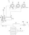
図1に示すように、火災感知システム1は火災感知器10、無線通信装置20、基地局30及び情報処理サーバ40から概略構成される。
火災感知器10及び無線通信装置20は建物や一般住宅等の防火対象施設内に配置され、基地局30及び情報処理サーバ40は防火対象施設外に配置される。
火災感知器10は火災発生時に本体の赤色の作動灯11の点灯や警報音の発生等の周知の手段により周囲に火災を報知すると共に火災の発生を火災受信機50に知らせる。
また、火災感知器10は移報接点12を備えている。火災感知器10の制御部(図示略)は火災を検知するとリレー接点を閉じて、或いはリレー接点を開いて、移報接点12を介して移報信号を無線通信装置20に送信する。
火災感知器10の種類としては移報接点12を備えていれば特に限定されず、火災による温度上昇、火災の煙、火災の炎を自動的に検知できる一般的なものであればよい。また、火災感知器10の取り付け場所も特に限定されないが、室内の天井や壁に取り付けるのが一般的である。また、火災感知器10として自動火災報知設備で使用される火災感知器ではなく住宅用火災警報器であってもよく、その場合は火災受信機50はなくてもよい。
火災受信機50としてはP型とR型のいずれを使用してもよく、また、後述する漏電火災警報器を使用してもよい。A first embodiment of a fire alarm system according to the present invention will be described.
As shown in FIG. 1, the fire detection system 1 is schematically composed of a
The
When a fire occurs, the
Further, the
The type of the
Either a P-type or an R-type may be used as the
無線通信装置20は移報接点12に有線接続されており、火災感知器10の近傍に設置される。火災感知器10と無線通信装置20は一対一で有線接続される。無線通信装置20は火災感知器10から送信された移報信号を受信して、火災源に関する情報を含む火災信号100をアンテナ21から基地局30に送信する。アンテナ21を筐体22内に格納してもよい。
火災源に関する情報とは無線通信装置20が取り付けられている場所に関する情報を指すものであり、例えば施設の住所及び名称、部屋の位置(1階、2階等)及び名称(101号室、食堂、○○の間等)、部屋の入居者の氏名、年齢、職業、電話番号等を指す。火災源に関する情報は無線通信装置20の記憶部23に格納されている。一つの火災報知システムが複数の無線通信装置20を備えている場合には、無線通信装置20毎に異なる内容の火災源に関する情報が記憶部23に格納されている。
無線通信装置20は基地局30と例えば3G,4G,LTE等の周知の手段で無線通信する。本発明では無線通信装置20は建物や部屋等の防火対象施設内に設置されているWi-Fiのアクセスポイントを利用して基地局30と無線通信することはない。The
The information about the fire source refers to information about the place where the
The
無線通信装置20の駆動は制御部24によって制御される。
筐体22の材質は日本消防検定で定められている条件を満たした例えばポリカーボネート樹脂等を用いるのが好ましく、耐熱温度は−10℃〜80℃を満たすのが好ましい。
無線通信装置20を火災感知器10と電気的に接続して駆動電源として利用してもよく、或いは一般的な乾電池又は充電池を電源として利用してもよい。乾電池や充電池を使用することにすれば簡便な装置構成の火災報知システムを得られる。
筐体22の一部に電池残量や無線の通信状態を示す表示部25を設けてもよい。また、筐体22の一部に、適時なタイミングで操作されることで基地局30への火災信号100の送信を遮断できる通信遮断スイッチ26を設けてもよい。例えば定期点検、部屋の清掃や消毒等の場合には、作業者が事前に通信遮断スイッチ26を操作することで無線通信装置20から基地局30への火災信号100の送信を停止することができる。The driving of the
It is preferable to use, for example, a polycarbonate resin or the like that satisfies the conditions defined by the Japanese Fire Service Certification, and it is preferable that the heat-resistant temperature satisfies −10 ° C. to 80 ° C.
The
A
情報処理サーバ40はインターネット(情報通信網)200を介して情報携帯端末60と無線で相互に各種情報の送受信が可能になっている。情報処理サーバ40をインターネット200上に設置することでいわゆるクラウドサーバにしてもよい。
火災信号100を受信した基地局30は情報処理サーバ40に火災信号100を送信する。情報処理サーバ40は火災信号100を受信して情報携帯端末60に送信する。
情報携帯端末60としてはいわゆる携帯電話、スマートフォン、タブレット等が挙げられ、施設の各部屋の入居者、管理人、消防団員、付近の住民、施設の所有者、入居者の近親者等の関係者が所有している。情報処理サーバ40は事前に登録された情報携帯端末60だけに火災信号100を送信することにすればよい。或いは、情報携帯端末60からの要求に応じて情報処理サーバ40が当該情報携帯端末60に火災信号100を送信することにしてもよい。更に、情報処理サーバ40が消防署に対して火災信号100を送信することにしてもよい。The
The
Examples of the information
また、情報処理サーバ40が火災信号100に含まれている火災源に関する情報に基づき、予め定めてある一つの情報携帯端末60にだけ火災信号100を送信することにしてもよい。この場合、火災信号100を受信した情報携帯端末60は、当該情報携帯端末60とグループ登録してある他の情報携帯端末61に対して火災信号100を一斉送信すればよい。
火災信号100を受信した情報携帯端末60,61の所有者は、所定の操作により火災源に関する情報の詳細を確認したり、情報携帯端末60,61の画面上に火災源の周囲の地図情報を表示させたりすることができる。
火災信号100を受信した情報携帯端末60,61の所有者は、所定の操作により火災源に関する情報の詳細を確認したり、情報携帯端末60,61の画面上に各種情報を表示させたりすることができる。各種情報としては例えば緊急連絡先の情報、避難場所の情報、火災発生場所付近の地図情報、建物図面、避難マニュアルや災害マニュアル等の各種マニュアル等であってもよい。また火災発生場所の付近に設置してあるカメラの撮影画像等であってもよい。尚、表示する情報の言語は日本語に限定されず外国語であってもよく、複数の外国語を同時に表示させてもよい。Further, the
The owners of the
The owners of the
[第2の実施の形態]
次に本発明の火災報知システムの第2の実施の形態について説明するが、上記第1の実施の形態と同一の構成となる箇所については同一の符号を付してその説明を省略する。
図2に示すように、本実施の形態の火災報知システム2では各火災感知器10と無線で接続される移報中継器70と、この移報中継器70に一対一で有線接続される無線通信装置20を備える点に特徴を有する。
火災感知器10は移報信号を無線送信する無線送信部13を備えている。また、移報中継器70は移報信号を無線受信する無線受信部71を備えている。火災感知器10、移報中継器70及び無線通信装置20は建物や一般住宅等の防火対象施設内に配置され、基地局30及び情報処理サーバ40は防火対象施設外に配置される。
火災感知器10の制御部(図示略)は火災を検知すると無線送信部13を介して移報信号を移報中継器70に送信する。移報中継器70は無線受信部71を介して移報信号を受信し、移報接点72を介して無線通信装置20に移報信号を送信する。
上記第1の実施の形態と同様に無線通信装置20は基地局30と例えば3G,4G,LTE等の周知の手段で無線通信する。無線通信装置20から火災信号100を受信した基地局30は情報処理サーバ40に火災信号100を送信し、情報処理サーバ40は火災信号100を受信して情報携帯端末60に送信する。[Second embodiment]
Next, a second embodiment of the fire alarm system according to the present invention will be described. Parts having the same configuration as the first embodiment are given the same reference numerals, and description thereof will be omitted.
As shown in FIG. 2, in the fire alarm system 2 of the present embodiment, a
The
When detecting a fire, the control unit (not shown) of the
As in the first embodiment, the
[第3の実施の形態]
次に本発明の火災報知システムの第3の実施の形態について説明するが、上記第1及び第2の実施の形態と同一の構成となる箇所については同一の符号を付してその説明を省略する。
図3に示すように、本実施の形態の火災報知システム3では複数の火災感知器10同士が有線で接続され、そのうちの一つの火災感知器10が火災受信機50と有線で接続されている。また、火災受信機50は無線通信装置20と一対一で有線接続されている点に特徴を有する。
複数の火災感知器10のうちの一つの火災感知器10が火災の発生を検知すると火災信号が有線で火災受信機50に送信される。火災受信機50は火災信号を受信し、移報接点51を介して有線で無線通信装置20に移報信号を送信する。
上記第1及び第2の実施の形態と同様に無線通信装置20は基地局30と無線通信する。無線通信装置20から火災信号100を受信した基地局30は情報処理サーバ40に火災信号100を送信し、情報処理サーバ40は火災信号100を受信して情報携帯端末60に送信する。
第2及び第3の実施の形態の火災報知システム2,3では複数の火災感知器10が火災受信機50や移報中継器70を介して1つの無線通信装置20と接続されるので、上記第1の実施の形態の構成と比較して無線通信装置20の数を減らすことができ、火災報知システムを設置する際のコストを抑制できる。[Third Embodiment]
Next, a description will be given of a third embodiment of the fire alarm system of the present invention. Parts having the same configuration as those of the first and second embodiments will be denoted by the same reference numerals and description thereof will be omitted. I do.
As shown in FIG. 3, in the
When one of the plurality of
The
In the
図4に示すように無線通信装置20に緊急通報装置としての機能を持たせてもよい。具体的には無線通信装置20に異常時通信用スイッチ80と誤報時通信用スイッチ81を配置する。上述の通り無線通信装置20は建物や一般住宅等の防火対象施設内に配置される。施設内の居住者や来訪者が体調を崩した、負傷した等の異常事態が発生した際に異常時通信用スイッチ80を押すことで、異常事態の発生が無線通信装置20から情報携帯端末60,61に通知される。また、火災が発生した際に火災感知器10が検知する前に付近に居る人が異常時通信用スイッチ80を押すことで火災発生を速やかに外部に通知することができる。異常時通信用スイッチ80が押されると施設のドアの施錠が解除される仕組みにしてもよい。誤って異常時通信用スイッチ80を押してしまった、或いは異常事態が解消された等の場合は誤報時通信用スイッチ81を押すことで情報携帯端末60,61への通知をキャンセルすることができる。異常時通信用スイッチ80が押された際に「送信が完了しました」、誤報時通信用スイッチ81が押された際に「異常なしを送信しました」等の音声メッセージが再生されるようにしてもよい。
情報携帯端末60,61に通知される情報として例えば避難場所等の情報、火災発生場所付近の地図情報、火災発生場所の付近に設置してあるカメラの撮影画像等であってもよい。
また、第2又は第3の実施の形態の火災報知システム2,3を複数配置し、各火災報知システム2,3からの火災発生等の情報を一台の情報携帯端末60で一括管理できるようにしてもよい。As shown in FIG. 4, the
Information notified to the information
Further, a plurality of
[第4の実施の形態]
次に本発明の火災報知システムの第4の実施の形態について説明するが、上記各実施の形態と同一の構成となる箇所については同一の符号を付してその説明を省略する。
図5に示すように、本実施の形態の火災報知システム4では警戒電路90に有線接続される漏電火災警報器91が無線通信装置20と一対一で有線接続されている点に特徴を有する。
漏電火災警報器91は警戒電路90上に漏電検出器(図示略)を備えている。漏電が発生した時に漏電火災警報器91は移報接点92を介して有線で無線通信装置20に移報信号を送信する。[Fourth embodiment]
Next, a fourth embodiment of a fire alarm system according to the present invention will be described. Parts having the same configuration as those of the above embodiments are given the same reference numerals and description thereof will be omitted.
As shown in FIG. 5, the fire alarm system 4 according to the present embodiment is characterized in that an earth
The ground
[第5の実施の形態]
次に本発明の火災報知システムの第5の実施の形態について説明するが、上記各実施の形態と同一の構成となる箇所については同一の符号を付してその説明を省略する。
図6に示すように、本実施の形態の火災報知システム5では無線通信端末20に戸外の表示灯93が一対一で有線接続されている点に特徴を有する。
火災感知器10の制御部(図示略)は火災を検知すると無線送信部13を介して移報信号を移報中継器70に送信する。移報中継器70は無線受信部71を介して移報信号を受信し、移報接点72を介して無線通信装置20に移報信号を送信すると同時に表示灯93に表示信号を送信して点灯させる。戸外の表示灯93が点灯することで戸外の第3者に火災の発生を知らせることができる。[Fifth Embodiment]
Next, a fifth embodiment of a fire alarm system according to the present invention will be described. Parts having the same configuration as those of the above embodiments are denoted by the same reference numerals, and description thereof will be omitted.
As shown in FIG. 6, the fire alarm system 5 of the present embodiment is characterized in that an
When detecting a fire, the control unit (not shown) of the
[第6の実施の形態]
次に本発明の火災報知システムの第6の実施の形態について説明するが、上記各実施の形態と同一の構成となる箇所については同一の符号を付してその説明を省略する。
図7に示すように、本実施の形態の火災報知システム6では無線通信端末20の他に第二の無線通信装置94を備えており、この第二の無線通信装置91と戸外の表示灯93が一対一で有線接続されている点に特徴を有する。
火災感知器10の制御部(図示略)は火災を検知すると無線送信部13を介して移報信号を移報中継器70に送信する。移報中継器70は無線受信部71を介して移報信号を受信し、移報接点72を介して無線通信装置20に移報信号を送信すると同時に、第二の無線通信装置94にも移報信号を無線送信する。第二の無線通信装置94は、無線受信部95を介して移報信号を受信し、接続された表示灯93に表示信号を送る。[Sixth Embodiment]
Next, a sixth embodiment of a fire alarm system according to the present invention will be described. Parts having the same configuration as those of the above embodiments are denoted by the same reference numerals, and description thereof will be omitted.
As shown in FIG. 7, the fire alarm system 6 of the present embodiment includes a second
When detecting a fire, the control unit (not shown) of the
本発明は、消防用設備が設置されていて点検を要する防火対象物や一般住宅等の既設の火災感知器の機能を補助する火災報知システムである。また、複数の火災感知器のうちどの火災感知器が作動したのかを既存の設備に大幅な改良を施すこと無く情報携帯端末から把握できる火災報知システムである。したがって、産業上の利用可能性を有する。 The present invention is a fire alarm system that assists the function of an existing fire detector, such as a fire prevention target that is installed with fire-fighting equipment and needs to be inspected or a general house. In addition, this fire alarm system allows the information portable terminal to know which of the plurality of fire detectors has been activated without making significant improvements to existing equipment. Therefore, it has industrial applicability.
1 火災感知システム
2 火災感知システム
3 火災感知システム
4 火災報知システム
5 火災報知システム
6 火災報知システム
10 火災感知器
11 作動灯
12 移報接点
13 無線送信部
20 無線通信装置
21 アンテナ
22 筐体
23 記憶部
24 制御部
25 表示部
26 通信遮断スイッチ
30 基地局
40 情報処理サーバ
50 火災受信機
51 移報接点
60 情報携帯端末
61 他の情報携帯端末
70 移報中継器
71 無線受信部
72 移報接点
80 異常時通信用スイッチ
81 誤報時通信用スイッチ
90 警戒電路
91 漏電火災警報器
92 移報接点
93 表示灯
94 第二の無線通信装置
95 無線受信部
100 火災信号
200 インターネット(情報通信網)
1 Fire detection system
2 Fire detection system
3 Fire detection system
4 Fire alarm system
5 Fire alarm system
6 Fire alarm system
10 Fire detector
11 Operation light
12 Signaling contacts
13 Wireless transmitter
20 Wireless communication devices
21 antenna
22 housing
23 Memory
24 Control unit
25 Display
26 Communication cutoff switch
30 base stations
40 Information processing server
50 fire receiver
51 Transfer contact
60 portable information terminals
61 Other information mobile terminals
70 Signal repeater
71 Wireless receiver
72 Transfer contact
80 Error communication switch
81 False alarm communication switch
90 Warning Circuit
91 Ground fault fire alarm
92 Transfer contact
93 Indicator
94 Second wireless communication device
95 Wireless receiver
100 Fire signal
200 Internet (information communication network)
Claims (11)
Translated fromJapanese前記火災感知器及び前記無線通信装置は防火対象施設内に配置され、前記基地局及び前記情報処理サーバは防火対象施設外に配置されるものであり、
火災発生時に前記火災感知器は火災を報知すると共に前記無線通信装置に移報信号を送信し、
前記移報信号を受信した前記無線通信装置は火災源に関する情報を含む火災信号を無線通信により前記基地局に送信し、
前記火災信号を受信した前記基地局は前記情報処理サーバに前記火災信号を送信し、
前記火災信号を受信した前記情報処理サーバは、前記火災信号を情報携帯端末に送信することを特徴とする火災報知システム。
A plurality of fire detectors having a transfer contact, a wireless communication device connected to the fire detector, a base station, and an information processing server connected to an information communication network,
The fire detector and the wireless communication device are disposed in a fire protection facility, the base station and the information processing server are disposed outside the fire protection facility,
When a fire occurs, the fire detector notifies the fire and transmits a transfer signal to the wireless communication device,
The wireless communication device that has received the notification signal transmits a fire signal including information on a fire source to the base station by wireless communication,
The base station that has received the fire signal transmits the fire signal to the information processing server,
The information processing server that has received the fire signal transmits the fire signal to an information portable terminal.
2. The fire alarm system according to claim 1, wherein the fire detector and the wireless communication device are connected one-to-one by wire.
A transmission relay that is wirelessly connected to the fire detector; the transmission relay is wired to the wireless communication device in a one-to-one connection, and the transmission signal is transmitted from the fire detector to the wireless communication device. 2. The fire alarm system according to claim 1, wherein the fire alarm system is transmitted to the wireless communication device via an alarm relay.
前記複数の火災感知器のうち一つの火災報知器と有線接続される火災受信機を備えており、前記火災受信機は前記無線通信装置と有線接続されていることを特徴とする請求項1に記載の火災報知システム。
The plurality of fire detectors are connected by wire,
A fire receiver connected to one of the plurality of fire detectors by a fire alarm is provided, and the fire receiver is connected to the wireless communication device by a wire. The fire alarm system described.
The information portable terminal that has received the fire signal transmits the fire signal to another information portable terminal that is group-registered with the information portable terminal, according to any one of claims 1 to 4, wherein Fire alarm system.
The fire alarm system according to any one of claims 1 to 5, wherein the wireless communication device includes a communication cutoff switch.
The fire alarm system according to any one of claims 1 to 6, wherein the wireless communication device includes an abnormal-time communication switch.
8. The fire alarm system according to claim 1, wherein the wireless communication device includes a false alarm communication switch.
5. The fire alarm system according to claim 1, further comprising an electric leakage fire alarm that is connected to an alarm circuit in a wired manner, wherein the electric leak fire alarm is connected to the wireless communication device in a wired manner.
An indicator light connected to the wireless communication device by wire is provided, and the wireless communication device transmits the fire signal to the base station and simultaneously transmits a display signal to the indicator light. Item 10. The fire alarm system according to any one of Items 1 to 9.
The wireless communication device includes a second wireless communication device wirelessly connected to the wireless communication device, wherein the second wireless device is connected to an indicator light by wire, and the wireless communication device transmits the fire signal to the base station. The fire alarm system according to any one of claims 1 to 9, wherein a display signal is transmitted to the indicator via the second wireless device at the same time.
Applications Claiming Priority (2)
| Application Number | Priority Date | Filing Date | Title |
|---|---|---|---|
| JP2018141916 | 2018-07-28 | ||
| JP2018141916 | 2018-07-28 |
Related Child Applications (1)
| Application Number | Title | Priority Date | Filing Date |
|---|---|---|---|
| JP2020091588ADivisionJP2020144933A (en) | 2018-07-28 | 2020-05-26 | Fire alarm system |
Publications (1)
| Publication Number | Publication Date |
|---|---|
| JP2020024692Atrue JP2020024692A (en) | 2020-02-13 |
Family
ID=69618821
Family Applications (2)
| Application Number | Title | Priority Date | Filing Date |
|---|---|---|---|
| JP2019137580APendingJP2020024692A (en) | 2018-07-28 | 2019-07-26 | Fire alarm system |
| JP2020091588APendingJP2020144933A (en) | 2018-07-28 | 2020-05-26 | Fire alarm system |
Family Applications After (1)
| Application Number | Title | Priority Date | Filing Date |
|---|---|---|---|
| JP2020091588APendingJP2020144933A (en) | 2018-07-28 | 2020-05-26 | Fire alarm system |
Country Status (1)
| Country | Link |
|---|---|
| JP (2) | JP2020024692A (en) |
Cited By (2)
| Publication number | Priority date | Publication date | Assignee | Title |
|---|---|---|---|---|
| CN113808355A (en)* | 2021-08-10 | 2021-12-17 | 安徽五维建筑规划设计有限公司 | Fireproof alarm system in building |
| US20230368650A1 (en)* | 2020-09-29 | 2023-11-16 | Rozetatech Co.,Ltd. | Fire alarm apparatus for unwanted alarm |
Citations (11)
| Publication number | Priority date | Publication date | Assignee | Title |
|---|---|---|---|---|
| JP2003296836A (en)* | 2002-03-29 | 2003-10-17 | Nohmi Bosai Ltd | Fire alarm facility |
| JP2004080294A (en)* | 2002-08-15 | 2004-03-11 | Nohmi Bosai Ltd | Crime prevention system |
| JP2004258761A (en)* | 2003-02-24 | 2004-09-16 | Nippon Telegr & Teleph Corp <Ntt> | Human body abnormality detection communication method, human body abnormality detection communication terminal, and temporal muscle movement detector |
| JP2004310407A (en)* | 2003-04-07 | 2004-11-04 | Tempearl Ind Co Ltd | Electrical leakage fire alarm equipped with tracking short-circuit detecting function |
| JP2005228078A (en)* | 2004-02-13 | 2005-08-25 | Hochiki Corp | Sensor base, control method and control program based on the sensor |
| JP2012203562A (en)* | 2011-03-24 | 2012-10-22 | Nohmi Bosai Ltd | Transfer output device and alarm system |
| JP2014186417A (en)* | 2013-03-22 | 2014-10-02 | Hochiki Corp | Alarm system |
| JP2015005151A (en)* | 2013-06-21 | 2015-01-08 | ホーチキ株式会社 | Alarm system |
| JP2016076238A (en)* | 2015-11-25 | 2016-05-12 | ホーチキ株式会社 | Cooperation system |
| JP2017004101A (en)* | 2015-06-05 | 2017-01-05 | 富士通株式会社 | Fire detection device, fire detection system, fire detection method, and fire detection program |
| JP2018049497A (en)* | 2016-09-23 | 2018-03-29 | 能美防災株式会社 | Regional disaster prevention information system |
Family Cites Families (1)
| Publication number | Priority date | Publication date | Assignee | Title |
|---|---|---|---|---|
| JP2008311702A (en)* | 2007-06-12 | 2008-12-25 | Sanyo Electric Co Ltd | Mobile terminal |
- 2019
- 2019-07-26JPJP2019137580Apatent/JP2020024692A/enactivePending
- 2020
- 2020-05-26JPJP2020091588Apatent/JP2020144933A/enactivePending
Patent Citations (11)
| Publication number | Priority date | Publication date | Assignee | Title |
|---|---|---|---|---|
| JP2003296836A (en)* | 2002-03-29 | 2003-10-17 | Nohmi Bosai Ltd | Fire alarm facility |
| JP2004080294A (en)* | 2002-08-15 | 2004-03-11 | Nohmi Bosai Ltd | Crime prevention system |
| JP2004258761A (en)* | 2003-02-24 | 2004-09-16 | Nippon Telegr & Teleph Corp <Ntt> | Human body abnormality detection communication method, human body abnormality detection communication terminal, and temporal muscle movement detector |
| JP2004310407A (en)* | 2003-04-07 | 2004-11-04 | Tempearl Ind Co Ltd | Electrical leakage fire alarm equipped with tracking short-circuit detecting function |
| JP2005228078A (en)* | 2004-02-13 | 2005-08-25 | Hochiki Corp | Sensor base, control method and control program based on the sensor |
| JP2012203562A (en)* | 2011-03-24 | 2012-10-22 | Nohmi Bosai Ltd | Transfer output device and alarm system |
| JP2014186417A (en)* | 2013-03-22 | 2014-10-02 | Hochiki Corp | Alarm system |
| JP2015005151A (en)* | 2013-06-21 | 2015-01-08 | ホーチキ株式会社 | Alarm system |
| JP2017004101A (en)* | 2015-06-05 | 2017-01-05 | 富士通株式会社 | Fire detection device, fire detection system, fire detection method, and fire detection program |
| JP2016076238A (en)* | 2015-11-25 | 2016-05-12 | ホーチキ株式会社 | Cooperation system |
| JP2018049497A (en)* | 2016-09-23 | 2018-03-29 | 能美防災株式会社 | Regional disaster prevention information system |
Cited By (2)
| Publication number | Priority date | Publication date | Assignee | Title |
|---|---|---|---|---|
| US20230368650A1 (en)* | 2020-09-29 | 2023-11-16 | Rozetatech Co.,Ltd. | Fire alarm apparatus for unwanted alarm |
| CN113808355A (en)* | 2021-08-10 | 2021-12-17 | 安徽五维建筑规划设计有限公司 | Fireproof alarm system in building |
Also Published As
| Publication number | Publication date |
|---|---|
| JP2020144933A (en) | 2020-09-10 |
Similar Documents
| Publication | Publication Date | Title |
|---|---|---|
| JP4807794B2 (en) | Disaster prevention monitoring system | |
| JP5245054B2 (en) | Alarm device and alarm system using the same | |
| KR20180023118A (en) | Fire Detection System | |
| JP6366942B2 (en) | Disaster prevention monitoring equipment and its remote operation method | |
| JP2020024692A (en) | Fire alarm system | |
| KR101220092B1 (en) | A management device for detector | |
| JP5907734B2 (en) | Cooperation system | |
| KR20150050544A (en) | Fire reporting system using machine-to-machine communication, anf method therefor | |
| KR102296974B1 (en) | FIRE HYDRANT BASED IoT FIRE ALARM SYSTEM | |
| KR20090097407A (en) | Wired / wireless hybrid automated detection system | |
| JP2020154911A (en) | Warning system | |
| JP6745687B2 (en) | Local disaster prevention information system | |
| JP6399572B1 (en) | Wireless communication device for fire and fire alarm system | |
| JP2024045412A (en) | Disaster prevention support system | |
| KR101527725B1 (en) | System to manage fire fighting facilities and method for managing thereof | |
| JP6517035B2 (en) | Alarm system and program | |
| KR101655827B1 (en) | Addressable repeater and addressable manual call point base on location confirmation | |
| KR20180014631A (en) | Crime prevention and call signal alarm system using sms service and method thereof | |
| JP6731814B2 (en) | Local disaster prevention information system | |
| JP3663843B2 (en) | Apartment house system with emergency broadcast line | |
| JP6836862B2 (en) | Alarm system | |
| KR20180043227A (en) | Crime prevention and call signal alarm system using sms service | |
| KR102327158B1 (en) | Remote firefighting management system using CCTV image | |
| JP6854945B2 (en) | Regional disaster prevention information system | |
| JP6553778B2 (en) | Disaster prevention monitoring equipment |
Legal Events
| Date | Code | Title | Description |
|---|---|---|---|
| A621 | Written request for application examination | Free format text:JAPANESE INTERMEDIATE CODE: A621 Effective date:20191206 | |
| A871 | Explanation of circumstances concerning accelerated examination | Free format text:JAPANESE INTERMEDIATE CODE: A871 Effective date:20191206 | |
| A975 | Report on accelerated examination | Free format text:JAPANESE INTERMEDIATE CODE: A971005 Effective date:20191217 | |
| A131 | Notification of reasons for refusal | Free format text:JAPANESE INTERMEDIATE CODE: A131 Effective date:20200131 | |
| A601 | Written request for extension of time | Free format text:JAPANESE INTERMEDIATE CODE: A601 Effective date:20200327 | |
| A02 | Decision of refusal | Free format text:JAPANESE INTERMEDIATE CODE: A02 Effective date:20200727 |