JP2020022865A - Shape sensor system for tracking interventional instruments and methods of using the same - Google Patents
Shape sensor system for tracking interventional instruments and methods of using the sameDownload PDFInfo
- Publication number
- JP2020022865A JP2020022865AJP2019207614AJP2019207614AJP2020022865AJP 2020022865 AJP2020022865 AJP 2020022865AJP 2019207614 AJP2019207614 AJP 2019207614AJP 2019207614 AJP2019207614 AJP 2019207614AJP 2020022865 AJP2020022865 AJP 2020022865A
- Authority
- JP
- Japan
- Prior art keywords
- sensor
- shape
- fiber
- fiducial
- image
- Prior art date
- Legal status (The legal status is an assumption and is not a legal conclusion. Google has not performed a legal analysis and makes no representation as to the accuracy of the status listed.)
- Granted
Links
- 238000000034methodMethods0.000titleabstractdescription46
- 210000003484anatomyAnatomy0.000claimsabstractdescription32
- 239000000835fiberSubstances0.000claimsdescription108
- 230000007246mechanismEffects0.000abstractdescription24
- 238000003032molecular dockingMethods0.000abstractdescription16
- 239000003550markerSubstances0.000abstractdescription13
- 238000010586diagramMethods0.000abstractdescription7
- 230000013011matingEffects0.000abstractdescription4
- 238000003384imaging methodMethods0.000description21
- 239000013307optical fiberSubstances0.000description20
- 238000012545processingMethods0.000description15
- 230000006870functionEffects0.000description9
- 230000033001locomotionEffects0.000description9
- 238000002591computed tomographyMethods0.000description8
- 230000003287optical effectEffects0.000description8
- 230000008569processEffects0.000description8
- 238000001356surgical procedureMethods0.000description8
- 238000005452bendingMethods0.000description7
- 239000000853adhesiveSubstances0.000description6
- 230000001070adhesive effectEffects0.000description6
- 238000002594fluoroscopyMethods0.000description6
- 238000001574biopsyMethods0.000description5
- 238000003860storageMethods0.000description5
- 238000001514detection methodMethods0.000description4
- 239000012636effectorSubstances0.000description4
- 210000004072lungAnatomy0.000description4
- 238000012014optical coherence tomographyMethods0.000description4
- 239000000126substanceSubstances0.000description4
- 230000000712assemblyEffects0.000description3
- 238000000429assemblyMethods0.000description3
- 210000001072colonAnatomy0.000description3
- 238000005516engineering processMethods0.000description3
- 210000002216heartAnatomy0.000description3
- 210000000936intestineAnatomy0.000description3
- 210000003734kidneyAnatomy0.000description3
- 239000000523sampleSubstances0.000description3
- 239000004065semiconductorSubstances0.000description3
- 230000001225therapeutic effectEffects0.000description3
- 238000004804windingMethods0.000description3
- 210000004556brainAnatomy0.000description2
- 230000008859changeEffects0.000description2
- 238000005253claddingMethods0.000description2
- 238000004891communicationMethods0.000description2
- 230000001010compromised effectEffects0.000description2
- 238000013461designMethods0.000description2
- 230000005672electromagnetic fieldEffects0.000description2
- 238000003331infrared imagingMethods0.000description2
- 238000003780insertionMethods0.000description2
- 230000037431insertionEffects0.000description2
- 238000013152interventional procedureMethods0.000description2
- 238000002595magnetic resonance imagingMethods0.000description2
- 238000012544monitoring processMethods0.000description2
- 239000002071nanotubeSubstances0.000description2
- 230000036961partial effectEffects0.000description2
- 238000002432robotic surgeryMethods0.000description2
- 230000005477standard modelEffects0.000description2
- 238000001931thermographyMethods0.000description2
- 238000013519translationMethods0.000description2
- 238000002604ultrasonographyMethods0.000description2
- 238000001069Raman spectroscopyMethods0.000description1
- 208000002847Surgical WoundDiseases0.000description1
- 230000001133accelerationEffects0.000description1
- 230000004913activationEffects0.000description1
- 230000002411adverseEffects0.000description1
- 230000005540biological transmissionEffects0.000description1
- 238000004140cleaningMethods0.000description1
- 238000003759clinical diagnosisMethods0.000description1
- 230000001427coherent effectEffects0.000description1
- 238000003745diagnosisMethods0.000description1
- 238000002651drug therapyMethods0.000description1
- 230000000694effectsEffects0.000description1
- 238000001839endoscopyMethods0.000description1
- 210000003238esophagusAnatomy0.000description1
- 238000002675image-guided surgeryMethods0.000description1
- 239000007943implantSubstances0.000description1
- 238000010348incorporationMethods0.000description1
- 230000001939inductive effectEffects0.000description1
- 238000002329infrared spectrumMethods0.000description1
- 230000000977initiatory effectEffects0.000description1
- 230000003993interactionEffects0.000description1
- 238000000608laser ablationMethods0.000description1
- 238000004519manufacturing processMethods0.000description1
- 238000005259measurementMethods0.000description1
- 239000002184metalSubstances0.000description1
- 238000002324minimally invasive surgeryMethods0.000description1
- 238000012986modificationMethods0.000description1
- 230000004048modificationEffects0.000description1
- 210000000056organAnatomy0.000description1
- 230000008447perceptionEffects0.000description1
- 238000001454recorded imageMethods0.000description1
- 238000011084recoveryMethods0.000description1
- 230000002829reductive effectEffects0.000description1
- 230000029058respiratory gaseous exchangeEffects0.000description1
- 230000004044responseEffects0.000description1
- 230000003068static effectEffects0.000description1
- 238000002211ultraviolet spectrumMethods0.000description1
- 238000001429visible spectrumMethods0.000description1
- 238000012800visualizationMethods0.000description1
Images


Classifications
- A—HUMAN NECESSITIES
- A61—MEDICAL OR VETERINARY SCIENCE; HYGIENE
- A61B—DIAGNOSIS; SURGERY; IDENTIFICATION
- A61B5/00—Measuring for diagnostic purposes; Identification of persons
- A61B5/06—Devices, other than using radiation, for detecting or locating foreign bodies ; Determining position of diagnostic devices within or on the body of the patient
- A61B5/061—Determining position of a probe within the body employing means separate from the probe, e.g. sensing internal probe position employing impedance electrodes on the surface of the body
- A61B5/064—Determining position of a probe within the body employing means separate from the probe, e.g. sensing internal probe position employing impedance electrodes on the surface of the body using markers
- A—HUMAN NECESSITIES
- A61—MEDICAL OR VETERINARY SCIENCE; HYGIENE
- A61B—DIAGNOSIS; SURGERY; IDENTIFICATION
- A61B34/00—Computer-aided surgery; Manipulators or robots specially adapted for use in surgery
- A61B34/20—Surgical navigation systems; Devices for tracking or guiding surgical instruments, e.g. for frameless stereotaxis
- A—HUMAN NECESSITIES
- A61—MEDICAL OR VETERINARY SCIENCE; HYGIENE
- A61B—DIAGNOSIS; SURGERY; IDENTIFICATION
- A61B34/00—Computer-aided surgery; Manipulators or robots specially adapted for use in surgery
- A61B34/30—Surgical robots
- A—HUMAN NECESSITIES
- A61—MEDICAL OR VETERINARY SCIENCE; HYGIENE
- A61B—DIAGNOSIS; SURGERY; IDENTIFICATION
- A61B34/00—Computer-aided surgery; Manipulators or robots specially adapted for use in surgery
- A61B34/10—Computer-aided planning, simulation or modelling of surgical operations
- A61B2034/101—Computer-aided simulation of surgical operations
- A61B2034/105—Modelling of the patient, e.g. for ligaments or bones
- A—HUMAN NECESSITIES
- A61—MEDICAL OR VETERINARY SCIENCE; HYGIENE
- A61B—DIAGNOSIS; SURGERY; IDENTIFICATION
- A61B34/00—Computer-aided surgery; Manipulators or robots specially adapted for use in surgery
- A61B34/20—Surgical navigation systems; Devices for tracking or guiding surgical instruments, e.g. for frameless stereotaxis
- A61B2034/2046—Tracking techniques
- A61B2034/2061—Tracking techniques using shape-sensors, e.g. fiber shape sensors with Bragg gratings
- A—HUMAN NECESSITIES
- A61—MEDICAL OR VETERINARY SCIENCE; HYGIENE
- A61B—DIAGNOSIS; SURGERY; IDENTIFICATION
- A61B34/00—Computer-aided surgery; Manipulators or robots specially adapted for use in surgery
- A61B34/30—Surgical robots
- A61B2034/301—Surgical robots for introducing or steering flexible instruments inserted into the body, e.g. catheters or endoscopes
- A—HUMAN NECESSITIES
- A61—MEDICAL OR VETERINARY SCIENCE; HYGIENE
- A61B—DIAGNOSIS; SURGERY; IDENTIFICATION
- A61B34/00—Computer-aided surgery; Manipulators or robots specially adapted for use in surgery
- A61B34/30—Surgical robots
- A61B2034/303—Surgical robots specifically adapted for manipulations within body lumens, e.g. within lumen of gut, spine, or blood vessels
- A—HUMAN NECESSITIES
- A61—MEDICAL OR VETERINARY SCIENCE; HYGIENE
- A61B—DIAGNOSIS; SURGERY; IDENTIFICATION
- A61B90/00—Instruments, implements or accessories specially adapted for surgery or diagnosis and not covered by any of the groups A61B1/00 - A61B50/00, e.g. for luxation treatment or for protecting wound edges
- A61B90/36—Image-producing devices or illumination devices not otherwise provided for
- A61B2090/363—Use of fiducial points
- A—HUMAN NECESSITIES
- A61—MEDICAL OR VETERINARY SCIENCE; HYGIENE
- A61B—DIAGNOSIS; SURGERY; IDENTIFICATION
- A61B90/00—Instruments, implements or accessories specially adapted for surgery or diagnosis and not covered by any of the groups A61B1/00 - A61B50/00, e.g. for luxation treatment or for protecting wound edges
- A61B90/39—Markers, e.g. radio-opaque or breast lesions markers
- A61B2090/3937—Visible markers
- A—HUMAN NECESSITIES
- A61—MEDICAL OR VETERINARY SCIENCE; HYGIENE
- A61B—DIAGNOSIS; SURGERY; IDENTIFICATION
- A61B90/00—Instruments, implements or accessories specially adapted for surgery or diagnosis and not covered by any of the groups A61B1/00 - A61B50/00, e.g. for luxation treatment or for protecting wound edges
- A61B90/39—Markers, e.g. radio-opaque or breast lesions markers
- A61B2090/3966—Radiopaque markers visible in an X-ray image
- A—HUMAN NECESSITIES
- A61—MEDICAL OR VETERINARY SCIENCE; HYGIENE
- A61B—DIAGNOSIS; SURGERY; IDENTIFICATION
- A61B2560/00—Constructional details of operational features of apparatus; Accessories for medical measuring apparatus
- A61B2560/04—Constructional details of apparatus
- A61B2560/0456—Apparatus provided with a docking unit
- A—HUMAN NECESSITIES
- A61—MEDICAL OR VETERINARY SCIENCE; HYGIENE
- A61B—DIAGNOSIS; SURGERY; IDENTIFICATION
- A61B5/00—Measuring for diagnostic purposes; Identification of persons
- A61B5/68—Arrangements of detecting, measuring or recording means, e.g. sensors, in relation to patient
- A61B5/6846—Arrangements of detecting, measuring or recording means, e.g. sensors, in relation to patient specially adapted to be brought in contact with an internal body part, i.e. invasive
- A61B5/6879—Means for maintaining contact with the body
Landscapes
- Health & Medical Sciences (AREA)
- Life Sciences & Earth Sciences (AREA)
- Engineering & Computer Science (AREA)
- Surgery (AREA)
- Medical Informatics (AREA)
- Public Health (AREA)
- Biomedical Technology (AREA)
- Heart & Thoracic Surgery (AREA)
- Veterinary Medicine (AREA)
- Molecular Biology (AREA)
- Animal Behavior & Ethology (AREA)
- General Health & Medical Sciences (AREA)
- Nuclear Medicine, Radiotherapy & Molecular Imaging (AREA)
- Robotics (AREA)
- Physics & Mathematics (AREA)
- Biophysics (AREA)
- Pathology (AREA)
- Human Computer Interaction (AREA)
- Endoscopes (AREA)
Abstract
Translated fromJapaneseDescription
Translated fromJapanese本開示は、低侵襲性処置を行うために患者の解剖学的構造をナビゲートするためのシステム及び方法に関し、より具体的には、介入器具を追跡するために形状センサーシステムを使用するシステム及び方法に関する。 The present disclosure relates to systems and methods for navigating a patient's anatomy to perform a minimally invasive procedure, and more particularly to systems that use a shape sensor system to track an interventional instrument and About the method.
低侵襲性医療技術は、介入手術の間に損傷を受ける組織の量を低減することを目的としており、それによって患者の回復時間、不快感及び有害な副作用が低減される。このような低侵襲性技術は、患者の解剖学的構造の自然(natural)開口部を通じて、又は1つ又は複数の外科的切開部を通じて行ってもよい。これらの自然開口部又は切開部を通じて、臨床医は、(外科用、診断用、治療用、又は生検用器具を含む)介入器具を挿入して、標的組織の位置に到達させることができる。標的組織の位置に到達させるために、低侵襲性介入器具を、肺、結腸、腸、腎臓、心臓、循環器系等の解剖学系における自然の又は外科的に形成された通路にナビゲートすることができる。既存のシステムでは、電磁(EM)ナビゲーションを使用して、患者の解剖学的構造を通る介入器具の動きを追跡することができる。EMナビゲーションシステムは、多くの手術に有用であるが、それらシステムは、手術部位において他の器具から磁気干渉を受けることがある。例えば、X線透視撮像システムのCアーム又は金属器具によって、EMナビゲーションシステムとの磁気干渉が発生し、介入器具の追跡に許容できないエラーを引き起こすことがある。 Minimally invasive medical techniques are aimed at reducing the amount of tissue damaged during interventional surgery, thereby reducing patient recovery time, discomfort and adverse side effects. Such minimally invasive techniques may be performed through a natural opening in the patient's anatomy or through one or more surgical incisions. Through these natural openings or incisions, clinicians can insert interventional instruments (including surgical, diagnostic, therapeutic, or biopsy instruments) to reach the location of the target tissue. Navigate a minimally invasive interventional device to a natural or surgically formed passage in an anatomical system such as the lung, colon, intestine, kidney, heart, circulatory system, etc. to reach the location of the target tissue be able to. Existing systems can use electromagnetic (EM) navigation to track the movement of an interventional instrument through a patient's anatomy. Although EM navigation systems are useful for many surgeries, they can be subject to magnetic interference from other instruments at the surgical site. For example, a C-arm or a metal instrument of a fluoroscopic imaging system may cause magnetic interference with the EM navigation system, causing unacceptable errors in tracking an interventional instrument.
改良されたナビゲーションシステム及び方法が、EMナビゲーションが適切でない又は損なわれ得る環境を含むような外科手術環境において、介入器具を追跡するために必要とされている。 Improved navigation systems and methods are needed to track interventional instruments in surgical environments, including those where EM navigation may not be appropriate or compromised.
本発明の実施形態は、詳細な説明に続く特許請求の範囲によって要約される。
一実施形態では、医療用追跡システムは、基準マーク式装置を有しており、この基準マーク式装置は、センサー装置の嵌合部と嵌合するように構成されたセンサードッキング機構を含む。センサードッキング機構は、嵌合部を既知の構成で保持する。基準マーク式装置は、少なくとも1つの画像形成可能な基準マーカーと、患者の解剖学的構造に取り付けるように構成された表面とを含む。Embodiments of the present invention are summarized by the claims that follow the detailed description.
In one embodiment, the medical tracking system includes a fiducial marking device, which includes a sensor docking mechanism configured to mate with a mating portion of the sensor device. The sensor docking mechanism holds the fitting portion in a known configuration. The fiducial marking device includes at least one imageable fiducial marker and a surface configured to attach to a patient's anatomy.
別の実施形態では、医療器具を追跡する方法は、解剖学的構造のモデルを受信するステップを含む。このモデルは、画像基準フレームを規定し、且つ少なくとも1つの基準マーカーの画像を含む。当該方法は、少なくとも1つの基準マーカーを含む基準マーク式装置が第1の形状センサー装置に結合された場合に、第1の形状センサー装置の基準部分を複数の基準マーカーに対して位置合せするステップをさらに含む。第1の形状センサー装置の基準部分は、少なくとも1つの基準マーカーに対して既知の構成で保持される。当該方法は、第1のセンサー基準フレームの第1の形状センサー情報を、第1の形状センサー装置の第1の形状センサーから受信するステップと、画像基準フレームと第1のセンサー基準フレームとの間の相関に基づいて、画像基準フレームにおける第1の形状センサーの姿勢を判定するステップをさらに含む。 In another embodiment, a method for tracking a medical device includes receiving a model of an anatomical structure. The model defines an image reference frame and includes an image of at least one reference marker. Aligning a reference portion of the first shape sensor device with respect to the plurality of reference markers when a fiducial mark-based device including at least one fiducial marker is coupled to the first shape sensor device. Further included. The reference portion of the first shape sensor device is held in a known configuration relative to the at least one reference marker. The method comprises the steps of: receiving first shape sensor information of a first sensor reference frame from a first shape sensor of a first shape sensor device; And determining the attitude of the first shape sensor in the image reference frame based on the correlation of
医療器具を追跡する方法は、解剖学的構造のモデルを受信するステップを含む。このモデルは、画像基準フレームを規定し、且つ少なくとも1つの基準マーカーのモデルを含む。当該方法は、第1の基準フレームの第1の形状センサー情報を、少なくとも1つの基準マーカーに対して既知の構成で保持された基準部分を含むような第1の形状センサーから受信するステップをさらに含む。当該方法は、第2の基準フレームの第2の形状センサー情報を、解剖学的構造内に位置付けされた第2の形状センサーから受信するステップをさらに含む。当該方法は、第1の基準フレーム、第2の基準フレーム、及び画像基準フレームの間の相関に基づいて、画像基準フレームにおける第2の形状センサーの姿勢を判定するステップをさらに含む。
本開示の追加の態様、特徴、及び利点は、以下の詳細な説明から明らかになるであろう。A method for tracking a medical device includes receiving a model of an anatomical structure. The model defines an image reference frame and includes a model of at least one reference marker. The method further comprises receiving the first shape sensor information of the first reference frame from the first shape sensor including a reference portion held in a known configuration for the at least one reference marker. Including. The method further includes receiving the second shape sensor information of the second reference frame from the second shape sensor located in the anatomical structure. The method further includes determining an orientation of the second shape sensor in the image reference frame based on a correlation between the first reference frame, the second reference frame, and the image reference frame.
Additional aspects, features, and advantages of the present disclosure will be apparent from the detailed description below.
本開示の態様は、添付の図面と併せて確認すると、以下の詳細な説明から最も良く理解される。この業界での標準的な慣例に従って、様々な特徴は一定の縮尺で描かれていないことを強調しておく。実際には、様々な特徴の寸法は、議論を明確にするために適宜拡大又は縮小することがある。また、本開示は、様々な実施例において参照符号及び/又は記号を繰り返して使用し得る。この繰返しは、簡略化と明瞭化を目的として行われており、説明される様々な実施形態及び/又は構成の間の関係をそれ自体で規定するものではない。 Aspects of the present disclosure are best understood from the following detailed description when read in conjunction with the accompanying drawings. It should be emphasized that, in accordance with standard practice in the industry, various features are not drawn to scale. In practice, the dimensions of the various features may be scaled up or down as appropriate to clarify the discussion. In addition, the present disclosure may repeatedly use reference signs and / or symbols in various embodiments. This repetition is for the sake of simplicity and clarity, and does not itself define a relationship between the various embodiments and / or configurations described.
本発明の態様の以下の詳細な説明において、開示された実施形態の完全な理解を提供するために、多数の特定の詳細について説明する。しかしながら、本開示の実施形態は、これら特定の詳細がなくても実施できることは当業者には明らかであろう。他の例では、周知の方法、手順、構成要素、及び回路は、本発明の実施形態の態様を不必要に曖昧にしないように詳細に説明していない。また、説明の不要な重複を避けるために、例示的な一実施形態について説明した1つ又は複数の構成要素又は動作は、他の例示的な実施形態について必要に応じて使用又は省略され得る。 In the following detailed description of aspects of the present invention, numerous specific details are set forth in order to provide a thorough understanding of the disclosed embodiments. However, it will be apparent to one skilled in the art that embodiments of the present disclosure may be practiced without these specific details. In other instances, well-known methods, procedures, components, and circuits have not been described in detail as not to unnecessarily obscure aspects of the embodiments of the present invention. Also, one or more components or operations described for one example embodiment may be used or omitted as appropriate for other example embodiments, in order to avoid unnecessary repetition of the description.
以下の実施形態は、3次元空間内の状態の観点から、様々な器具及び器具の部分について説明する。本明細書で使用される場合に、用語「位置」は、3次元空間(例えば、直交座標X,Y,Zに沿った並進3自由度)における対象物又は対象物の一部の位置を指す。本明細書で使用される場合に、用語「向き」は、対象物又は対象物の一部の回転配置(例えば、ロール、ピッチ、及びヨーの回転3自由度)を指す。本明細書で使用される場合に、用語「姿勢」は、並進自由度の少なくとも1つの自由度における対象物又は対象物の一部の位置、及び回転自由度の少なくとも1つの自由度における対象物又は対象物の一部の向き(合計6つの自由度まで)を指す。本明細書で使用される場合に、用語「形状」は、細長い対象物に沿って測定された姿勢、位置、又は向きのセットを指す。 The following embodiments describe various instruments and instrument parts in terms of state in three-dimensional space. As used herein, the term “position” refers to the position of an object or a portion of an object in three-dimensional space (eg, three degrees of freedom translation along rectangular coordinates X, Y, Z). . As used herein, the term "orientation" refers to a rotational arrangement of an object or a portion of an object (e.g., three degrees of freedom in roll, pitch, and yaw rotations). As used herein, the term “posture” refers to the position of an object or portion of an object in at least one of the degrees of freedom of translation, and the object in at least one of the degrees of freedom of rotation. Or, a part of the object (to a total of six degrees of freedom). As used herein, the term "shape" refers to a set of poses, positions, or orientations measured along an elongated object.
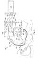
図1を参照すると、例えば、外科用、診断用、治療用、又は生検用処置において使用されるロボット介入システムが、参照符号100によって概して示されている。図1に示されるように、ロボット介入システム100は、一般的に、患者Pが配置される手術台Oに又はその近くに取り付けられたロボットアセンブリ102を含む。介入器具システム104が、ロボットアセンブリ102に作動可能に結合される。オペレータ入力システム106によって、外科医又は臨床医Sが手術部位を視認して、介入器具システム104の動作を制御することが可能になる。 Referring to FIG. 1, a robotic intervention system used, for example, in a surgical, diagnostic, therapeutic, or biopsy procedure is indicated generally by the
オペレータ入力システム106は、通常、手術台Oと同じ部屋に位置するような外科医コンソールに配置することができる。もっとも、外科医又は臨床医Sは、患者Pとは異なる部屋又は完全に異なる建物に位置し得ることを理解すべきである。オペレータ入力システム106は、一般的に、介入器具システム104を制御するための1つ又は複数の制御装置を含む。制御装置(複数可)は、ハンドグリップ、ジョイスティック、トラックボール、データグローブ、トリガーガン、手動操作制御装置、音声認識装置、タッチスクリーン、身体動き又は存在センサー等の多数の様々な入力装置を含んでもよい。いくつかの実施形態では、制御装置(複数可)は、ロボットアセンブリの介入器具と同じ自由度で提供され、テレプレゼンスを外科医に提供する、又は制御装置(複数可)が器具と一体化されるような知覚を提供し、それによって外科医は、器具を直接的に制御する強い感覚を有することになる。他の実施形態では、制御装置(複数可)は、関連する介入器具より多い又は少ない自由度を有しており、依然としてテレプレゼンスを外科医に提供することができる。いくつかの実施形態では、制御装置(複数可)は、6つの自由度で動く手動入力装置であり、(例えば、顎部を把握して閉じる、電位を電極に印加する、薬物療法を送達する等をするための)器具を作動するための作動ハンドルも含み得る。 The
ロボットアセンブリ102は、介入器具システム104をサポートしており、且つ1つ又は複数の非サーボ制御リンク(例えば、所定の位置に手動で位置付けされ且つロックされる1つ又は複数のリンク、一般的にセットアップ構造と呼ばれる)及びロボットマニピュレータの運動学的構造を含むことができる。ロボットアセンブリ102は、介入器具104の入力装置を駆動させる複数のアクチュエータ(例えば、モータ)を含む。これらのモータは、制御システム(例えば、制御システム112)からのコマンドに応答して、能動的に動く。モータは、介入器具104に結合された場合に、自然に又は手術によって形成された解剖学的開口部に介入器具を前進させる及び/又は介入器具の先端部を複数の自由度で動かすことができる駆動システムを含み、3つの自由度の直線運動(例えば、X,Y,Z座標軸に沿った直線運動)及び3つの自由度の回転運動(例えば、X,Y,Z座標軸回りの回転)を含むことができる。また、モータを使用して、生検装置等の顎部で組織を把持するための、器具の関節接合可能なエンドエフェクタを作動させることができる。 The
ロボット介入システム100は、ロボットアセンブリの器具に関する情報を受信するための1つ又は複数のサブシステムを有するセンサーシステム108も含む。このようなサブシステムは、位置センサーシステム(例えば、電磁(EM)センサーシステム)、カテーテルチップの及び/又は器具104の可撓性本体に沿った1つ又は複数のセグメントの、位置、向き、速度、姿勢、及び/又は形状を判定するための形状センサーシステム、及び/又はカテーテルシステムの先端部から画像を捕捉するための可視化システムを含んでもよい。
ロボット介入システム100は、センサーシステム108のサブシステムによって生成された手術部位及び介入器具104の画像を表示するための表示システム110も含む。ディスプレイ110及びオペレータ入力システム106は、オペレータが、実質的に真のものが作業空間に存在しているかのように視認して、介入器具システム104及びオペレータ入力システム106を制御することができるように向き合せされる。真のものの存在は、表示された組織画像が、オペレータに、このオペレータが画像位置に物理的に存在しており且つ画像の視点から組織を直接的に視認しているかのように表示されることを意味する。
代替的に又は追加的に、表示システム110は、コンピュータ断層撮影(CT)、磁気共鳴画像診断(MRI)、X線透視法、サーモグラフィ、超音波、光コヒーレンストモグラフィー(OCT)、赤外線画像、インピーダンスイメージング、レーザーイメージング、ナノチューブX線イメージング等の撮像技術を使用して手術前に記録され及び/又はモデル化された手術部位の画像を提示することができる。提示された手術前画像は、2次元、3次元、又は4次元(例えば、時間ベース又は速度ベースの情報を含む)画像及びモデルを含むことができる。 Alternatively or additionally,
いくつかの実施形態では、表示システム110は、介入器具の実際の位置が手術前又は同時の画像と共に記録され(例えば、動的に参照され)、外科用器具のチップの位置における内部手術部位のバーチャル画像を外科医に提供するような仮想の可視化画像を表示することができる。 In some embodiments, the
他の実施形態では、表示システム110は、介入器具の実際の位置が、(手術前に記録された画像を含む)以前の画像又は同時画像と共に記録され、手術部位における介入器具のバーチャル画像を外科医に提示するような仮想の可視化画像を表示することができる。介入器具を制御する外科医を支援するために、介入器具104の一部の画像をバーチャル画像に重畳してもよい。 In other embodiments, the
ロボット介入システム100は、制御システム112も含む。制御システム112は、介入器具システム104、オペレータ入力システム106、センサーシステム108、及び表示システム110の間で制御を行うための、少なくとも1つのプロセッサ(図示せず)、典型的には複数のプロセッサを含む。制御システム112は、プログラムされた命令(例えば、命令を格納するコンピュータ可読媒体)も含み、本明細書で説明される方法の一部又は全てを実施する。制御システム112が、図1の簡略化した概略図に単一のブロックとして示されているが、このシステムは、多数のデータ処理回路を含んでもよく、処理の一部は、必要に応じて、ロボットアセンブリ102で又はこれに隣接して実行され、一部は、オペレータ入力システム106等で実行される。多種多様な集中型又は分散型データ処理アーキテクチャのいずれかを用いてもよい。同様に、プログラムされた命令は、多数の別々のプログラム又はサブルーチンとして実装してもよく、又はそれら命令は、本明細書で説明するロボットシステムの多数の他の態様に組み込んでもよい。一実施形態では、制御システム112は、ブルートゥース(登録商標)、IrDA、ホームRF、IEEE802.11、DECT及び無線テレメトリ等の無線通信プロトコルをサポートする。
いくつかの実施形態では、制御システム116は、1つ又は複数のサーボ制御装置を含んでおり、介入器具システム104からオペレータ入力システム106の対応する1つ又は複数のサーボモータに力及びトルクフィードバックを提供することができる。サーボ制御装置(複数可)は、ロボットアセンブリ102に命令する信号を送信して、患者の身体の開口部を介してこの身体内の内部手術部位内に延びる介入器具104を移動させることもできる。任意の適切な従来の又は特殊なサーボ制御装置を使用してもよい。サーボ制御装置は、ロボットアセンブリ102から分離される、又はロボットアセンブリ102と一体化することができる。いくつかの実施形態では、サーボ制御装置及びロボットアセンブリは、患者の身体に隣接して位置付けされたロボットアームカートの一部として設けられる。 In some embodiments, control system 116 includes one or more servo controls to provide force and torque feedback from
制御システム112は、仮想可視化システムをさらに含み、介入器具104にナビゲーション支援を提供することができる。仮想可視化システムを使用する仮想ナビゲーションは、解剖学的通路の3次元構造に関連して取得されたデータセットに対する参照に基づくものである。具体的には、仮想可視化システムは、コンピュータ断層撮影(CT)、磁気共鳴画像診断(MRI)、X線透視法、サーモグラフィ、超音波、光コヒーレンストモグラフィー(OCT)、赤外線画像、インピーダンスイメージング、レーザーイメージング、ナノチューブX線イメージング等の撮像技術を使用して記録され及び/又はモデル化された手術部位の画像を処理する。ソフトウェアを使用して、記録した画像を、部分的な又は全体的な解剖学的臓器又は解剖学的領域の2次元又は3次元モデルに変換する。モデルは、通路及びそれら接続部の様々な位置や形状を示す。モデルを生成するために使用した画像を、臨床診断中に手術前又は手術中に記録してもよい。代替実施形態では、仮想可視化システムは、標準的なモデル(すなわち、特定の患者ではない)、又は標準モデル及び患者の固有データのハイブリッドを使用してもよい。モデル及びこのモデルによって生成されたバーチャル画像は、運動の1つ又は複数の段階の間に(例えば、肺の吸気/呼気サイクルの間に)又は誘起された解剖学的動作(例えば、患者の再位置付け又は器具によって生じる変形)の間に、変形可能な解剖学的領域の静的な姿勢を表すことができる。
仮想ナビゲーション手順の間に、センサーシステム108を使用して、患者の解剖学的構造に対する器具のおおよその位置を計算することができる。この位置を使用して、患者の解剖学的構造のマクロレベル追跡画像及び患者の解剖学的構造の内部バーチャル画像の両方を生成することができる。仮想可視化システム等からの手術前に記録された手術画像と一緒に介入実装形態を記録し且つ表示するために光ファイバセンサーを使用する様々なシステムが、知られている。このようなシステムは、例えば、2011年5月13日に出願された、”Medical System Providing Dynamic Registration of a Model of an Anatomical Structure for Image-Guided Surgery”を開示する米国特許出願第13/107,562号に記載されており、この文献は、その全体を参照することにより本明細書に組み込まれる。 During the virtual navigation procedure, the
ロボット介入システム100は、照明システム、操作制御システム、洗浄システム、及び/又は吸引システム等のオプションのオペレーション及びサポートシステム(図示せず)をさらに含んでもよい。代替実施形態では、ロボットシステムは、複数のロボットアセンブリ及び/又は複数のオペレータ入力システムを含んでもよい。マニピュレータアセンブリの正確な数は、他の要因の中でもとりわけ、外科手術及び手術室内の空間的制約に依存する。複数のオペレータ入力システムを併置してもよく、又はそれらを別々の位置に配置してもよい。複数のオペレータ入力システムによって、複数のオペレータが1つ又は複数のマニピュレータアセンブリを種々の組合せで制御することを可能にする。
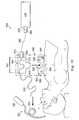
図2には、ロボット介入システム100の介入器具システム104として使用されるような介入器具システム200が示されている。あるいはまた、介入器具システム200は、非ロボット診査処置、又は内視鏡検査等の従来の手動操作介入器具を伴う処置で使用することができる。 FIG. 2 shows an
器具システム200は、器具本体204に結合されたカテーテルシステム202を含む。カテーテルシステム202は、基端部217及び先端部218を有する細長い可撓性カテーテル本体216を含む。一実施形態では、可撓性本体216は、約3ミリメートルの外径を有する。他の可撓性本体の外径は、これよりも大きくても小さくてもよい。カテーテルシステム202は、先端部218におけるカテーテルチップの及び/又は本体216に沿った1つ又は複数のセグメント224の、位置、向き、速度、姿勢、及び/又は形状を判定するための形状センサー222を含む。先端部218と基端部217との間の本体216の全長を、セグメント224に効果的に分割することができる。器具システム200がロボット介入システム100の介入器具システム104である場合に、形状センサー222は、センサーシステム108の構成要素であってもよい。器具システム200が手動操作される又は他に非ロボット処置で使用される場合に、形状センサー222を、形状センサーからデータを取得するとともに受信した形状データを処理するような追跡システムに結合することができる(例えば、図3参照)。 The
形状センサーシステム222は、可撓性カテーテル本体216と整列した(例えば、内部チャネル(図示せず)内に設けられた又は外付けされた)光ファイバを含む。一実施形態では、光ファイバは、約200μmの直径を有する。他の実施形態では、この寸法は、これよりも大きくても小さくてもよい。
形状センサーシステム222の光ファイバは、カテーテルシステム202の形状を判定するための光ファイバの曲げセンサーを形成する。1つの代替形態では、ファイバブラッグ回折格子(FBGs)を含む光ファイバが、1つ又は複数の次元における構造のひずみ測定を提供するために使用される。光ファイバの形状及び相対位置を3次元で監視するための様々なシステム及び方法が、2005年7月13日に出願された、”Fiber optic position and shape sensing device and method relating thereto”を開示する米国特許出願第11/180,389号、2004年7月16日に出願された、”Fiber-optic shape and relative position sensing”を開示する米国仮特許出願第60/588,336号、1998年6月17日に出願された、”Optical Fibre Bend Sensor”を開示する米国特許第6,389,187号に記載されており、これらの文献は、それら全体を参照することにより本明細書に組み込まれる。他の代替形態では、レイリー散乱、ラマン散乱、ブリルアン散乱、蛍光散乱等の他のひずみ感知技術を用いるセンサーが適している。他の代替形態では、カテーテルの形状は、他の技術を用いて判定してもよい。
例えば、カテーテルの先端チップ姿勢の履歴が、ナビゲーション表示を再読み込みする期間又は交互に行う動作(例えば、吸入及び呼気)の期間よりも短い時間間隔に亘って保存される場合に、この姿勢履歴を使用して、その時間間隔に亘ってこの装置の形状を再構築することができる。別の例として、過去の姿勢、位置、又は向きデータは、呼吸等の交互に行われる動作のサイクルに従った器具の既知の点として保存することができる。この保存データを使用して、カテーテルに関する形状情報を開発することができる。あるいはまた、カテーテルに沿って配置されたEMセンサー等の一連の位置センサーを、形状検出のために使用することができる。あるいはまた、手術中に器具上のEMセンサー等の位置センサーからの履歴データを使用して、特に解剖学的通路が略静止している場合には、器具の形状を表すことができる。あるいはまた、外部磁場により制御される位置又は向きを有する無線装置を、形状検出のために使用することができる。その位置の履歴を使用して、ナビゲートする通路の形状を判定することができる。The optical fibers of
For example, if the history of the distal tip posture of the catheter is stored for a shorter time interval than the period of re-reading the navigation display or the period of the alternating operation (for example, inhalation and expiration), this posture history is stored. Can be used to reconstruct the shape of the device over that time interval. As another example, past posture, position, or orientation data can be stored as a known point on the instrument following a cycle of alternating movements, such as breathing. This stored data can be used to develop shape information about the catheter. Alternatively, a series of position sensors, such as an EM sensor, located along the catheter can be used for shape detection. Alternatively, historical data from a position sensor, such as an EM sensor, on the instrument during surgery can be used to represent the shape of the instrument, especially if the anatomical passage is substantially stationary. Alternatively, a wireless device having a position or orientation controlled by an external magnetic field can be used for shape detection. The history of the location can be used to determine the shape of the path to navigate.
この実施形態では、光ファイバは、単一クラッド(cladding)内に複数のコアを含んでもよい。各コアは、十分な距離を有しており且つクラッドによってコアを分離するシングルモードであってもよく、それによって各コアの光は、他のコアで搬送される光と殆ど相互作用しない。他の実施形態では、コアの数は変化してもよく、又は各コアを別個の光ファイバに含めてもよい。 In this embodiment, the optical fiber may include multiple cores within a single cladding. Each core may be single mode, having a sufficient distance and separating the cores by cladding, so that light in each core has little interaction with light carried in other cores. In other embodiments, the number of cores may vary, or each core may be included on a separate optical fiber.
いくつかの実施形態では、FBGのアレイが各コア内に設けられる。各FBGは、屈折率の空間周期性を生成するように、コアの屈折率の一連の変調を含む。間隔は、各屈折率変化による部分的な反射が、狭帯域の波長についてコヒーレントとなるように追加されるように選択され、こうしてより広帯域を通過させながら、この狭帯域の波長のみを反射することができる。FBGの製造中に、変調によって、既知の距離だけ間隔が置かれ、こうして既知の帯域幅の波長の反射を引き起こす。しかしながら、ひずみがファイバコアに誘起された場合に、変調の間隔は、コアのひずみ量に応じて変化する。あるいはまた、光ファイバの屈曲に伴って変化する後方散乱又は他の光学的現象を使用して、各コア内のひずみを決定することができる。 In some embodiments, an array of FBGs is provided in each core. Each FBG includes a series of modulations of the refractive index of the core to create a spatial periodicity of the refractive index. The spacing is chosen such that the partial reflections from each index change are added to be coherent for the narrowband wavelength, thus reflecting only this narrowband wavelength while passing through a wider band. Can be. During fabrication of the FBG, the modulation is spaced by a known distance, thus causing reflection of wavelengths of a known bandwidth. However, when distortion is induced in the fiber core, the modulation interval changes according to the amount of distortion in the core. Alternatively, backscattering or other optical phenomena that change with bending of the optical fiber can be used to determine the strain in each core.
こうして、ひずみを測定するために、光をファイバに送り、戻ってくる光の特性が測定される。例えば、FBGは、ファイバのひずみとその温度との関数である反射波長を生成する。このFBG技術は、英国のブラックネルにあるSmart Fibres Ltd.等の様々な供給先から市販されている。ロボット手術についてFBG技術の位置センサーでの使用は、2006年7月20日に出願された、”Robotic Surgery System Including Position Sensors Using Fiber Bragg Gratings”を開示する米国特許第7,930,065号に記載されており、この文献は、その全体を参照することにより本明細書に組み込まれる。 Thus, to measure the strain, light is sent to the fiber and the properties of the returning light are measured. For example, an FBG produces a reflected wavelength that is a function of the strain of the fiber and its temperature. This FBG technology is commercially available from various sources, such as Smart Fibers Ltd., located in Bracknell, UK. The use of FBG technology in position sensors for robotic surgery is described in U.S. Patent No. 7,930,065, filed July 20, 2006, which discloses "Robotic Surgery System Including Position Sensors Using Fiber Bragg Gratings." And this document is incorporated herein by reference in its entirety.
マルチコア光ファイバに力を加えた場合に、光ファイバの曲げによって、コアにひずみが誘起され、このひずみは、各コアにおける波長シフトを監視することによって測定される。ファイバの軸線から外れて配置された2つ以上のコアを有することにより、光ファイバの曲げによって、各コアに異なるひずみが誘起される。これらのひずみは、ファイバの局所的な曲げの程度の関数である。そのため、例えばFBGを含むコアの領域が、ファイバが曲げられる点に位置する場合に、これらの点での曲げ量を決定するために使用することができる。FBG領域の既知の間隔と組み合わされるこれらのデータを使用して、ファイバの形状を再構築することができる。このようなシステムは、バージニア州、ブラックスバーグのLuna Innovation. Inc.によって説明されている。 When a force is applied to a multi-core optical fiber, the bending of the optical fiber induces strain in the core, which is measured by monitoring the wavelength shift in each core. By having two or more cores positioned off the axis of the fiber, bending of the optical fiber induces different strains in each core. These strains are a function of the degree of local bending of the fiber. So, for example, if the area of the core containing the FBG is located at points where the fiber is bent, it can be used to determine the amount of bending at those points. These data, combined with the known spacing of the FBG regions, can be used to reconstruct the shape of the fiber. Such a system is described by Luna Innovation. Inc. of Blacksburg, Virginia.
説明したように、光ファイバを使用して、カテーテルシステム202の少なくとも一部の形状を監視することができる。具体的には、光ファイバを通過する光は、器具システム202の形状を検出するために、及び外科手術を支援するためのその形状情報を利用するために処理される。センサーシステム(例えば、図3に示されるようなセンサーシステム108又は別のタイプの追跡システム)は、介入器具システム202の形状を判定するために使用される光を生成し且つ検出するためのデータ取得(interrogation)システムを含むことができる。次に、この情報を使用して、介入器具の部品の速度及び加速度等の関連する他の変数を決定することができる。センシング(感知)は、ロボットシステムによって作動される自由度にだけ制限することができる、又は受動(例えば、関節同士間の剛性部材の非作動状態の曲げ)及び能動(例えば、器具の作動状態の運動)の両方の自由度に適用することができる。 As described, optical fibers can be used to monitor the shape of at least a portion of the
介入器具システムは、手術部位において他の器具からの例えば磁気干渉により信頼性が損なわれる、又は他のナビゲーション追跡システムがより高い信頼性を有する場合に、オペレータ又は自動システム(例えば、制御システム112の機能)によって停止されるような位置センサーシステム220(例えば、電磁(EM)センサーシステム)をオプションで含んでもよい。 An interventional instrument system may be used by an operator or an automated system (e.g., control system 112) if the reliability is compromised, e.g., by magnetic interference from other instruments at the surgical site, or if other navigation tracking systems are more reliable. Function) may optionally include a position sensor system 220 (eg, an electromagnetic (EM) sensor system) as stopped by the function.
位置センサーシステム220は、1つ又は複数の導電性コイルを含み、外部で発生した電磁場を受けるEMセンサーシステムであってもよい。次に、EMセンサーシステム220の各コイルは、外部で発生した電磁場に対してコイルの位置及び向きが依存するような特性を有する誘導電気信号を生成する。一実施形態では、EMセンサーシステムは、6つの自由度、例えば3つの位置座標X,Y,Z及び基点のピッチ、ヨー、及びロールを示す3つの方位角、又は5つの自由度、例えば3つの位置座標X,Y,Z及び基点のピッチ及びヨーを示す2つの方位角を測定するように構成され且つ位置付けすることができる。EMセンサーシステムについての更なる説明は、1999年8月11日に出願された、”Six-Degree of Freedom Tracking System Having a Passive Transponder on the Object Being Tracked”を開示する米国特許第6,380,732号に提供されており、この文献は、その全体を参照することにより本明細書に組み込まれる。 The
可撓性カテーテル本体216は、補助ツール226を受容するようにサイズ決めされ且つ形状が形成されたチャネルを含む。補助ツールは、例えば画像捕捉プローブ、生検装置、レーザーアブレーションファイバ、又は他の外科用、診断用、又は治療用ツールを含んでもよい。補助ツールは、メス、ブレード、光ファイバ、又は電極等の単一の作業部材を有するエンドエフェクタを含んでもよい。他のエンドエフェクタは、例えば鉗子、把持器、はさみ、又はクリップアプライヤ等のペアの又は複数の作業部材を含んでもよい。電気的に作動されるエンドエフェクタの例として、電気外科電極、トランスデューサ、センサー等が挙げられる。様々な実施形態では、補助ツール226は、表示するために処理される画像(映像を含む)を取り込むために、可撓性カテーテル本体216の先端部218近傍に配置された立体又は単眼カメラを含むチップ部分を有するような画像捕捉プローブであってもよい。画像捕捉プローブは、取り込まれた画像データを送信するための、カメラに結合されたケーブルを含んでもよい。あるいはまた、画像捕捉装置は、撮像システムに結合するファイバースコープ等の光ファイバ束であってもよい。画像捕捉装置は、例えば、画像データを可視スペクトルで取り込む又は画像データを可視及び赤外又は紫外スペクトルで取り込むような単一の又はマルチスペクトルとすることができる。
可撓性カテーテル本体216は、器具本体204と先端部218との間に延びるケーブル、リンク機構、又は他の操作制御装置(図示せず)を収容してもよく、例えば先端部の点線の回転(versions)により示されるように、先端部218を制御可能に曲げる又は回動させることができる。器具システム200がロボットアセンブリによって作動される実施形態では、器具本体204は、ロボットアセンブリの電動駆動要素に結合する駆動入力部を含んでもよい。器具システム200が手動で操作される実施形態では、器具本体204は、器具システムの動作を手動で制御するための、把持機構、手動アクチュエータ、及び他の構成要素を含んでもよい。カテーテルシステムは、操作可能であってもよく、又は代替的に、オペレータ制御によって器具を曲げるための組込メカニズムを有していないような操作不能であってもよい。更に又は代替的に、可撓性本体216は、介入器具が標的の手術部位で展開され且つ使用されるような1つ又は複数の管腔を規定することができる。 The
様々な実施形態では、介入器具システム202は、肺の検査、診断、生検、又は処置に使用される気管支鏡又は気管支カテーテル等の可撓性気管支用器具であってもよい。このシステムは、結腸、腸、腎臓、脳、心臓、循環器系等を含む様々な解剖学系において、自然に又は外科的に形成された接続通路を介した、他の組織のナビゲーションや処置にも適している。 In various embodiments, the
図3には、本開示の実施形態に係る介入器具追跡システム250が示されている。追跡システム250は、可撓性カテーテル本体254及び器具本体256を有する介入器具252を含む。この実施形態では、介入器具252は、器具200と同様であるが、EM位置センサーは、形状検出システムによって、臨床医により使用される追跡情報が提供され患者の解剖学的構造を通る介入器具の経路が決定される際に、無効に又は省略され得る。光ファイバ形状センサー253は、介入器具252内に延びる。追跡システム250は、センサー装置258も含む。センサー装置258は、基準マーク式(fiduciary)装置260及び基準本体262を含む。基準マーク式装置260は、接着剤或いは他の化学的又は機械的な固定機構を使用して患者Pに取外し可能に取り付けられるような表面264を含む。いくつかの実施形態では、基準マーク式装置260は、患者の解剖学的構造の外面に取り付けられるが、代替実施形態では、基準マーク式装置は、例えば、経鼻、経直腸、経膣、経食道等により患者の内部解剖学的構造に取り付けてもよい。更に他の代替形態では、基準マーク式装置260を、ステント等の仮インプラントに取り付けてもよい。 FIG. 3 illustrates an interventional
基準マーク式装置260は、X線透視法やCT等の撮像技術を用いて表示される少なくとも1つの基準マーク266を含むことができる。基準マーク式マーカーの設計の例は、2009年4月23日に出願された、”Fiducial Marker Design and Detection for Locating Surgical Instrument in Images”を開示する米国特許出願第12/428,657号に提供されており、この文献は、その全体を参照することにより本明細書に組み込まれる。基準マーク式マークは、完全な3次元姿勢の位置合せを提供するのに十分な詳細を有することができる。例えば、基準マーク式マークは、3次元姿勢の位置合せを可能にするような不均一なリンク長さを含む「L」字形状を有してもよい。様々な他の実施形態では、基準マーク式装置260は、撮像技術の下で表示され且つ基準点(fiducial)として機能するような特徴(例えば、溝、突起、又は他の形状)を含んでもよい。様々な他の実施形態では、基準マーク式装置260自体は、基準点として機能することができ、いくつかの実施形態では3次元姿勢の判定を容易にするような形状を有してもよい。 The fiducial
基準マーク式装置260は、基準本体262の嵌合部270と嵌合するように構成されたセンサードッキング機構268をさらに含む。センサードッキング機構268は、基準マーク式装置260を基準本体262に着脱可能に接続するための、1つ又は複数の凹部、凸部、機械式締結具、接着剤ファスナー、磁気留め具、又は他の構成要素を含んでもよい。接続された場合に、センサードッキング機構268及び嵌合部270によって、基準マーク式装置260及び基準本体262が既知の所定の固定した空間関係に維持される。 The reference
図4には、基準マーク式装置302及び基準本体304を含むセンサー装置300の代替実施形態が示されている。この実施形態では、基準マーク式装置302の複数のセンサードッキング機構306が、基準本体304の嵌合部308に整列され且つ取り付けられる。 FIG. 4 shows an alternative embodiment of a
図3を再び参照すると、基準本体262は、基準部分251及び形状センサーファイバ253を所定の基準形状に保持するように構成されたセンサーホルダ272を含む。この実施形態では、センサーホルダ272は、形状センサーファイバ253を受容するとともに、このファイバを基準本体262に対して所定の形状構成で維持するような連続巻線チャネルである。代替実施形態では、センサーホルダは、センサーファイバが基準本体に対して所定の形状を維持するように取り付けられるような一連の離散的な取付け点であってもよい。基準本体262は、センサーファイバ253が、追跡システム250の他の構成要素に接続するように終端処理されたセンサー接続部品274をさらに含む。 Referring again to FIG. 3, the
追跡システム250は、形状センサーファイバ253の現在の形状を判定するために使用される光を生成し且つ検出するためのデータ取得システム276をさらに含む。データ取得システム276は、臨床医に表示するために返送されたデータも処理することができる。データ取得システム276は、コネクタ278を含む。ファイバーリンク280が、コネクタ282,284の間に延びる。この実施形態では、ファイバーリンク280の光ファイバは、感知されず(すなわち、ファイバーリンクの形状のデータが取得されない)、形状センサー253から感知した光情報をデータ取得システム276に伝達するように機能する。使用する際に、ファイバーリンク280のコネクタ282は、コネクタ274に接続され、コネクタ284は、コネクタ278に接続される。
使用する際に、基準マーク式装置260は、患者Pに取り付けられる。患者Pの手術前又は手術中の撮像は、取り付けられた基準マーク式装置260を用いて実施される。基準マーカー266は、その画像内に表示され、こうして、患者Pの解剖学的構造に対して、及びこの画像に生成された患者の解剖学的構造の2次元、3次元、又は4次元(すなわち、時間を含む移動)のモデルに対して固定した基準フレームを提供する(すなわち、基準マーカー266は、患者の解剖学的構造のモデルデータの少なくとも一部に対して既知の関係を有する基準点のセットを規定する)。様々な他の実施形態では、オプションの基準マーカー、要素、或いは基準部分251等の基準本体262は、形状センサーファイバ253が基準点として使用される場合に、患者Pの手術前の撮像の間に基準マーク式装置に結合することができる。 In use, the
いずれにしても、介入処置を開始する前に、基準本体262は、基準マーク式装置260に結合され、ドッキング機構268及び嵌合部270によって基準マーク式装置に対して所定の構成で保持される。このように接続されると、形状センサーファイバ253の基準部分251によって、基準マーク式装置260に対する形状センサーファイバの基端部の既知の姿勢が提供される。データ取得システム276は、形状センサーファイバ253からデータを取得して、可撓性カテーテル本体254の先端チップの姿勢及び形状を判定する。カテーテル本体254の感知した相対的な姿勢及び形状データは、基準マーク式装置260に位置合せされる形状センサーファイバの基準部分251に関して既知である。こうして、形状センサーファイバの基準部分251についての位置合せ情報を用いてカテーテル本体254の相対的な姿勢及び形状情報を処理することによって、患者Pに対するカテーテル本体254の姿勢及び形状が提供される。 In any event, prior to commencing the intervention procedure,
基準本体及び基準マーク式装置の上述した固定され且つ事前に規定された構成についての様々な代替実施形態では、基準本体及び基準マーク式装置の構成は、測定可能なバリエーションで変化する。この構成は、既知であるが、事前に規定する代わりに測定可能とされる。例えば、基準マーク式装置及び基準本体は、短い可変距離だけ離間してもよいが、この短い距離は、静電容量センサー、圧電センサー、又は光学センサーを含むセンサーベースの変動追跡システムによって連続的に監視し且つ記録することができる。別の例として、測定可能な変動は、例えばモータのエンコーダを使用して測定されるような挿入方向の距離であってもよい。 In various alternative embodiments of the above-described fixed and predefined configuration of the fiducial body and fiducial marking device, the configuration of the fiducial body and fiducial marking device varies in measurable variations. This configuration is known but can be measured instead of pre-defined. For example, the fiducial-marked device and the fiducial body may be separated by a short variable distance, which is continuously reduced by a sensor-based variable tracking system that includes a capacitive sensor, a piezoelectric sensor, or an optical sensor. It can be monitored and recorded. As another example, the measurable variation may be a distance in the insertion direction as measured, for example, using a motor encoder.
図5には、介入器具追跡システム250を使用する方法320が示されている。322において、処理システムは、患者Pの解剖学的構造のモデルを受信する。このモデルは、取り付けられた基準マーク式装置260で撮影された患者Pの画像から生成される。このモデルは、画像基準フレームを規定する。基準マーク266が、モデルに表示される。324において、基準マーク式装置260が、基準本体262に結合される。こうして、形状センサーファイバ253の基準部分251が、基準マーク式装置260に対して所定の構成で保持される。こうして、基準部分251は、基準マーク式装置260に位置合せされる。326において、形状センサー情報が、処理するために(形状センサーファイバ253の基準フレームに)受信される。328において、形状センサーファイバ253の先端部(又は他の部分)の姿勢が、画像基準フレームと形状センサー253の基準フレームとの間の位置合せに基づいて、画像基準フレームにおいて判定される。必要に応じて、可撓性本体254の先端部の姿勢に対応するような、画像基準フレームからの画像が表示される。画像は、患者モデルからの画像に重畳される、可撓性本体254の先端部の画像であってもよい。いくつかの実施形態では、患者モデルは、(例えば、可撓性本体254の姿勢に対して患者モデルをフィッティングすることにより)形状センサー情報に基づいて更新してもよい。あるいはまた、画像は、可撓性本体の先端部から視た画像に対応するような患者モデルの内側から視た画像であってもよい。 FIG. 5 illustrates a
図6には、本開示の実施形態に係る介入器具追跡システム350が示されている。追跡システム350は、可撓性カテーテル本体354及び器具本体356を有する介入器具352を含む。光ファイバ形状センサー353が、介入器具352内に延びる。追跡システム350は、センサー装置358も含む。センサー装置358は、基準マーク式装置360を含んでおり、この基準マーク式装置は、接着剤或いは他の化学的又は機械的な固定機構を使用して患者Pに取外し可能に取り付けられるような表面364を含む。様々な実施形態では、基準マーク式装置360は、X線透視法やCT等の画像処理技術を用いて表示される少なくとも1つの基準マーク366を含む。様々な他の実施形態では、基準マーク式装置360は、基準として使用される物理的特徴、或いはその基準マーク式装置自体が基準とされるような特徴を含むことができる。基準マーク式装置360は、形状センサー353のコネクタ374と嵌合するドッキング機構373も含む。 FIG. 6 illustrates an interventional
基準マーク式装置360は、形状センサーファイバ353の基準部分351とドッキングし、この部分351を所定の基準形状に保持するように構成されたセンサーホルダ372を含む。この実施形態では、センサーホルダ372は、形状センサーファイバ253の基準部分351を受容するとともに、このファイバを基準マーク式装置360に対して既知の事前に規定された形状構成に維持するような連続巻線チャネルである。センサー接続部品274によって、センサーファイバ353が終端処理され、嵌合ドッキング機構373に着脱可能に接続される。様々な代替実施形態では、既知の構成は、前述したように測定可能な変数であってもよい。 The fiducial
追跡システム350は、形状センサーファイバ353の現在の形状を判定するために使用される光を生成し且つ検出するためのデータ取得システム376をさらに含む。データ取得システム376は、臨床医に表示するために返送されたデータも処理することができる。データ取得システム376は、コネクタ378を含む。ファイバーリンク380が、コネクタ382,384の間に延びる。この実施形態では、ファイバーリンク380の光ファイバは、感知されず(すなわち、ファイバーリンクの形状のデータが取得されない)、形状センサー353から感知した光情報をデータ取得システム376に伝達するように機能する。使用する際に、ファイバーリンク380のコネクタ382は、コネクタ374に接続され、コネクタ384は、コネクタ378に接続される。この実施形態では、コネクタ374,382は、基準マーク式装置360の一部内に接続される。
使用する際に、基準マーク式装置360は、患者Pに取り付けられる。患者Pの手術前又は手術中の撮像は、取り付けられた基準マーク式装置360を用いて実施される。存在する場合に、基準マーカー366が、その画像内に表示され、こうして、患者Pの解剖学的構造に対して、及びこの画像に生成された患者の解剖学的構造の2次元又は3次元モデルに対して固定した基準を提供する。他の実施形態では、センサーホルダ372のような機構等の基準マーク式装置360上の代替の基準要素、センサーホルダ372に配置された形状センサーファイバ353の基準部分351、或いは基準マーク式装置360自体を、固定した患者基準を確立するために画像化することができる。 In use, the
介入処置を開始する前に、形状センサーファイバ353の基準部分351は、コネクタ382に接続されたコネクタ374を用いてセンサーホルダ372内に配置される。こうして、基準部分351は、基準マーク式装置360に対して、センサーホルダ372の所定の構成に固定されて保持される。このように接続されると、形状センサーファイバ353の基準部分351によって、基準マーク式装置360に対する形状センサーファイバの基端部の既知の向きが提供される。データ取得システム376は、形状センサーファイバ353からデータを取得して、可撓性カテーテル本体354の先端チップの姿勢及び形状を判定する。カテーテル本体354の感知した相対的な姿勢及び形状データは、基準マーク式装置360に位置合せされるファイバ基準部分351に対して既知である。こうして、形状センサーファイバの基準部分351についての位置合せ情報を用いてカテーテル本体354の相対的な姿勢及び形状情報を処理することによって、患者Pに対するカテーテル本体354の姿勢及び形状が提供される。 Prior to initiating the intervention procedure,
図7には、介入器具追跡システム350を使用する方法400が示されている。402において、処理システムが、患者Pの解剖学的構造のモデルを受信する。このモデルは、取り付けられた基準マーク式装置360で撮影された患者Pの画像から生成される。このモデルは、画像基準フレームを規定する。基準マーク366が、モデルに表示される。404において、基準部分351が、基準マーク式装置360に結合される。こうして、形状センサーファイバ353の基準部分351は、基準マーク式装置360に対して所定の構成で保持される。このようにして、基準部分351は、基準マーク式装置360に位置合せされる。406において、形状センサー情報が、処理するために(形状センサーファイバ353の基準フレームに)受信される。408において、形状センサーファイバ353の先端部(又は他の部分)の姿勢が、画像基準フレームと形状センサー353の基準フレームとの間の相関に基づいて、画像基準フレームにおいて判定される。必要に応じて、可撓性本体354の先端部の姿勢に対応するような、画像基準フレームからの画像が、表示される。この画像は、患者モデルからの画像に重畳される、可撓性本体354の先端部の画像であってもよい。いくつかの実施形態では、患者モデルは、(例えば、可撓性本体254の姿勢に対して患者モデルをフィッティングすることにより)形状センサー情報に基づいて更新してもよい。あるいはまた、画像は、可撓性本体の先端部から視た画像に対応するような患者モデルの内部から視た画像であってもよい。 FIG. 7 illustrates a
図8には、本開示の実施形態に係る介入器具追跡システム450が示されている。追跡システム450は、可撓性カテーテル本体454及び器具本体456を有する介入器具452を含む。光ファイバ形状センサー453が、介入器具452内に延びる。形状センサー453の基端部が、センサー接続部品451で終端処理される。追跡システム450は、センサー装置458も含む。センサー装置458は、基準マーク式装置460及び基準治具462を含む。基準マーク式装置460は、接着剤或いは他の化学的又は機械的な固定機構を使用して患者Pに取外し可能に取り付けられた表面464を含む。いくつかの実施形態では、基準マーク式装置460は、X線透視法又はCT等の撮像技術を用いて表示される少なくとも1つの基準マーク466を含むことができる。様々な他の実施形態では、基準マーク式装置360は、基準点として使用される物理的特徴を含む、或いはその基準マーク式装置自体を基準にすることができる。 FIG. 8 illustrates an interventional
光ファイバーセンサー形状470が、基準マーク式装置460から延びる。基準マーク式装置460は、形状センサーファイバ470の基準部分471と嵌合するとともにこの基準部分471を所定の基準形状に保持するように構成されたドッキング機構として機能するようなセンサーホルダ472を含む。この実施形態では、センサーホルダ472は、形状センサーファイバ470を受容するとともに、このファイバの基準部分471を基準マーク式装置460に対して所定の形状構成に維持するような連続巻線チャネルである。センサーファイバ470の基端部が、センサー接続部品474で終端処理される。この実施形態では、ファイバ470の基準部分471は、この基準部分が基準マーク式装置に対して固定され且つ撮像技術を用いて表示される際に、基準マークとして機能することができる。 A fiber
様々な代替実施形態では、形状センサー470は、基準マーク式装置460と基準治具462との間の相対的な姿勢を測定するために、省略してもよいし、他の構成要素によって補完してもよい。様々なセンサーベース追跡システムのいずれかを使用して、基準マーク式装置460に対する基準治具462の相対姿勢を追跡することができる。このような追跡システムは、容量センサー、圧電センサー、又は光学センサーを含んでもよい。 In various alternative embodiments, the
追跡システム450は、形状センサーファイバ453及び形状センサーファイバ470の現在の形状を判定するために使用される光を生成し且つ検出するためのデータ取得システム476をさらに含む。データ取得システム476は、臨床医に表示するために返送されたデータも処理することができる。データ取得システム476は、コネクタ478,479を含む。ファイバーリンク480が、コネクタ482,484の間に延びる。ファイバーリンク486が、コネクタ488,490の間に延びる。この実施形態では、ファイバーリンク480,486の光ファイバは、感知されず(つまり、ファイバーリンクの形状のデータが取得されない)、形状センサー453,470とデータ取得システム476との間で感知した光情報を伝達するように機能する。
使用する際に、基準マーク式装置460は、患者Pに取り付けられる。患者Pの手術前又は手術中の撮像は、患者の解剖学的構造に取り付けられた基準マーク式装置460を用いて実施される。この実施形態では、撮像中に、形状センサーファイバ470を基準マーク式装置460に取り付けてもよい。存在する場合に、基準マーカー466が、その画像内に表示され、こうして、患者Pの解剖学的構造に対して、及び画像に生成された患者の解剖学的構造の2次元又は3次元モデルに対して固定した基準を提供する。他の実施形態では、センサーホルダ472のような機構等の基準マーク式装置460上の代替的な基準要素、センサーホルダ472に配置された形状センサーファイバ470の基準部分471、或いは基準マーク式装置460自体を、固定した患者基準を確立するために画像化することができる。 In use,
介入処置を開始する前に、センサーファイバ470の基端部及び取付けコネクタ474が、基準治具462に結合される。センサーファイバ453の基端部及び取付けコネクタ451も、基準治具462に結合される。基準治具は、センサーファイバ470,451の基端部を固定位置に保持し、且つ互いに対して及び基準治具に対して向き合せさせる。ファイバーリンク480のコネクタ482は、コネクタ451に接続され、コネクタ484は、データ取得システム476のコネクタ478に接続される。ファイバーリンク486のコネクタ488は、コネクタ474に接続され、コネクタ490は、データ取得システム476のコネクタ479に接続される。データ取得システム476は、形状センサーファイバ453からデータを取得して、可撓性カテーテル本体454の先端チップの姿勢及び形状を判定する。データ取得システム476は、形状センサーファイバ470からもデータを取得して、形状センサーファイバ470の基準部分471の姿勢を判定する。カテーテル本体454の感知した相対的な姿勢及び形状データは、基準治具451に関して既知であり、基準部分471の相対姿勢及び形状データは、基準治具462に関して既知である。コネクタ451,474が互いに対して固定されており、且つ基準治具462に対して固定されるので、基準治具によって、形状センサーファイバ453,470の間に固定した位置合せが提供される。こうして、形状センサーファイバ470の基準部分471についての位置合せ情報を用いてカテーテル本体454の相対的な姿勢及び形状情報を処理することによって、患者Pに対する基準治具462の姿勢及び形状が提供される。 Before starting the interventional procedure, the proximal end of the
図9には、介入器具追跡システム450を使用する方法500が示されている。502において、処理システムが、患者Pの解剖学的構造のモデルを受信する。このモデルは、取り付けられた基準マーク式装置460で撮影された患者Pの画像から生成される。このモデルは、画像基準フレームを規定する。基準マーク466が、モデルに表示される。形状センサーファイバ453が、基準治具462に結合され、形状センサーファイバ470が、基準治具462に結合される。504において、形状センサー情報が、処理するために(形状センサーファイバ470の基準フレームにおいて)形状センサーファイバ470から受信される。506において、形状センサー情報が、処理するために(形状センサーファイバ453の基準フレームにおいて)形状センサーファイバ453から受信される。508において、形状センサーファイバ353の先端部の姿勢が、画像基準フレーム、形状センサー353の基準フレーム、及び形状センサー470基準フレームの間の相関に基づいて、画像基準フレームにおいて判定される。必要に応じて、可撓性本体454の先端部の姿勢に対応するような、画像基準フレームからの画像が、表示される。この画像は、患者モデルからの画像に重畳される、可撓性本体454の先端部の画像であってもよい。あるいはまた、画像は、可撓性本体の先端部から視た画像に対応するような患者モデルの内部から視た画像であってもよい。 FIG. 9 illustrates a
図10には、本開示の実施形態に係る介入器具追跡システム550が示されている。追跡システム550は、可撓性カテーテル本体554及び器具本体556を有する介入器具552を含む。光ファイバ形状センサー553は、介入器具552とは別体であり、介入器具552内に挿入するようにサイズ決めされる。追跡システム550は、センサー装置558も含む。センサー装置558は、基準マーク式装置560及び基準本体562を含む。基準マーク式装置560は、接着剤或いは他の化学的又は機械的な固定機構を使用して患者Pに取外し可能に取り付けられた表面564を含む。基準マーク式装置560は、X線透視法やCT等の撮像技術を用いて表示される少なくとも1つの基準マーク566を含む。基準マーク式装置560は、基準本体562の嵌合部570に嵌合するように構成されたセンサードッキング機構568をさらに含む。センサードッキング機構568は、基準マーク式装置560を基準本体562に着脱可能に接続するための、1つ又は複数の凹部、凸部、機械式締結具、接着剤ファスナー、磁気留め具、又は他の構成要素を含んでもよい。接続されたときに、センサードッキング機構568及び嵌合部570によって、基準マーク式装置560及び基準本体562を、固定した、事前に規定された空間的関係で維持する。 FIG. 10 illustrates an interventional
基準本体562は、形状センサーファイバ553の基準部分551を所定の基準形状に保持するように構成されたセンサーホルダ572を含む。この実施形態では、センサーホルダ572は、形状センサーファイバ553を受容するとともに、このファイバを基準本体562に対して所定の形状構成で維持するような連続巻線チャネルである。代替実施形態では、センサーホルダは、センサーファイバが基準本体に対して既知の、所定の形状を維持するように取り付けられるような一連の離散的な取り付け点であってもよい。基準本体562は、センサーファイバ553が追跡システム550の他の構成要素に接続するために終端処理されるようなセンサー接続部品574をさらに含む。様々な代替実施形態の公知の構成は、前述したように測定可能な変数であってもよい。
追跡システム550は、形状センサーファイバ553の現在の形状を判定するために使用される光を生成し且つ検出するためのデータ取得システム576をさらに含む。データ取得システム576は、臨床医に表示するために返送されたデータも処理することができる。データ取得システム576は、コネクタ578を含む。ファイバーリンク580が、コネクタ582,584の間に延びる。この実施形態では、ファイバーリンク580の光ファイバは、感知されず(すなわち、ファイバーリンクの形状のデータ取得されない)、形状センサー553から感知した光情報をデータ取得システム576に伝達するように機能する。使用する際に、ファイバーリンク580のコネクタ582は、コネクタ574に接続され、コネクタ584は、コネクタ578に接続される。
使用する際に、基準マーク式装置560は、患者Pに取り付けられる。患者Pの手術前又は手術中の撮像は、取り付けられた基準マーク式装置560を用いて実施される。基準マーカー566が、その画像内に表示され、こうして、患者Pの解剖学的構造に対して、及びこの画像に生成された患者の解剖学的構造の2次元又は3次元モデルに対して固定した基準を提供する。介入処置を開始する前に、センサーファイバ553が、可撓性カテーテル本体554内に挿入される。基準本体562は、基準マーク式装置560に結合され、且つドッキング機構568及び嵌合部570により基準マーク式装置に対して所定の構成で保持される。このように接続されると、形状センサーファイバ553の基準部分551によって、基準マーク式装置560に対して形状センサーファイバの基端部の既知の向きが提供される。データ取得システム576は、形状センサーファイバ553からデータを取得して、可撓性カテーテル本体554の先端チップの姿勢及び形状を判定する。カテーテル本体554の感知した相対的な姿勢及び形状データが、基準マーク式装置560に位置合せされる、形状センサーファイバの基準部分551に関して既知である。こうして、形状センサーファイバの基準部分551についての位置合せ情報を用いてカテーテル本体554の相対的な姿勢及び形状情報を処理することによって、患者Pに対するカテーテル本体554の姿勢及び形状が提供される。センサーファイバ553からの情報を処理する方法の更なる詳細は、図5で説明したものと同様である。 In use, the
この実施形態では、センサーファイバ553は、可撓性カテーテル本体から分離可能であり、したがって、センサーファイバ553は、ファイバ553を受容するようにサイズ決めされた管腔を有する気管支鏡又は他のデバイスを含むような他のタイプの器具と一緒に使用することができる。 In this embodiment, the
本開示のシステム及び方法は、肺の気管支の接続通路に使用するために説明してきたが、それらシステム及び方法は、結腸、腸、腎臓、脳、心臓、循環器系等を含む様々な解剖学系において、自然に又は外科的に形成された接続通路を介した、他の組織のナビゲーションや処置にも適している。本開示の方法及び実施形態は、非介入的用途にも適している。 Although the systems and methods of the present disclosure have been described for use in the bronchial connection passages of the lungs, the systems and methods may be used in various anatomical systems, including the colon, intestine, kidney, brain, heart, circulatory system, and the like. It is also suitable for navigation and treatment of other tissues in the system via naturally or surgically formed connecting passages. The methods and embodiments of the present disclosure are also suitable for non-intrusive use.
本発明の実施形態の1つ又は複数の要素は、制御システム112等のコンピュータシステムのプロセッサ上で実行されるソフトウェアで実装してもよい。ソフトウェアで実装された場合に、本発明の実施形態の要素は、基本的に、必要なタスクを実行するためのコードセグメントである。伝送媒体又は通信リンクを通じた搬送波で具現化されるコンピュータデータ信号を介してダウンロードしてもよいプログラム又はコードセグメントを、プロセッサ可読記憶媒体又はデバイスに格納することができる。プロセッサ可読記憶装置は、光媒体、半導体媒体、及び磁気媒体を含む、情報を格納することができる任意の媒体含むことができる。プロセッサ可読記憶装置の例は、半導体装置、半導体記憶装置、読取り専用メモリ(ROM)、フラッシュメモリ、消去可能なプログラマブル読取り専用メモリ(EPROM)、フロッピーディスク、CD−ROM、光ディスク、ハードディスク、又は他の記憶装置等の電子回路を含む。コードセグメントは、インターネット、イントラネット等のコンピュータネットワークを介してダウンロードしてもよい。 One or more elements of an embodiment of the invention may be implemented in software running on a processor of a computer system, such as
提示されるプロセス及び表示は、任意の特定のコンピュータ又は他の装置に本質的に関連しなくてもよいことに注意されたい。様々なこれらのシステムに必要な構成は、特許請求の範囲において要素として表される。また、本発明の実施形態は、特定のプログラミング言語を参照して記載されるわけではない。本明細書に説明されているように、様々なプログラミング言語が、本発明の教示を実践するために使用することができることを理解されるであろう。 Note that the processes and displays presented may not be intrinsically related to any particular computer or other device. The required structure for a variety of these systems is expressed as elements in the claims. In addition, embodiments of the present invention are not described with reference to any particular programming language. It will be understood that a variety of programming languages can be used to practice the teachings of the present invention, as described herein.
本発明の特定の例示的な実施形態について説明し且つ添付の図面に示してきたが、このような実施形態は、単なる例示であり、広範な本発明に対する制限ではなく、本発明の実施形態は、様々な他の修正が当業者に想起されるので、図示され及び説明された特定の構成及び配置に限定されるものではないことを理解すべきである。
While specific exemplary embodiments of the present invention have been described and illustrated in the accompanying drawings, such embodiments are merely illustrative and not restrictive of the invention, in which It should be understood that various other modifications will occur to those skilled in the art and are not limited to the specific configurations and arrangements shown and described.
Claims (5)
Translated fromJapanese解剖学的構造を表すモデルデータセットを記憶するメモリであって、前記モデルデータセットは、1つ又は複数の基準点に対して既知の関係を含む、前記解剖学的構造の複数のモデルデータ点を有する、メモリと;
前記解剖学的構造と相互作用する器具の光ファイバーセンサーから形状データを受信するとともに、前記形状データに基づいて、前記器具と前記モデルデータセットとを位置合せするように構成されたプロセッサであって、前記形状データは、1つ又は複数の基準点に対して既知の関係を有する、プロセッサと;を有する、
システム。A system, wherein the system is:
A memory storing a model data set representing an anatomical structure, wherein the model data set includes a plurality of model data points of the anatomical structure including a known relationship to one or more reference points. Having a memory;
A processor configured to receive shape data from a fiber optic sensor of the instrument interacting with the anatomical structure, and to align the instrument with the model data set based on the shape data; A processor having a known relationship to one or more reference points;
system.
請求項1に記載のシステム。The processor is further configured to update the model data set based on the shape data.
The system according to claim 1.
請求項2に記載のシステム。The processor is configured to form the posture of the instrument using the shape data, and to update the model data set by fitting the model data set to the posture.
The system according to claim 2.
請求項1に記載のシステム。The processor is further configured to generate an image data set including model image data generated from the model data set and appliance image data generated from the shape data, wherein the appliance image data is the model image data. Aligned with image data,
The system according to claim 1.
請求項4に記載のシステム。
Receiving the image data set, further comprising a display for displaying the appliance image data superimposed on the model image data,
The system according to claim 4.
Applications Claiming Priority (3)
| Application Number | Priority Date | Filing Date | Title |
|---|---|---|---|
| US201361799524P | 2013-03-15 | 2013-03-15 | |
| US61/799,524 | 2013-03-15 | ||
| JP2018121615AJP6620191B2 (en) | 2013-03-15 | 2018-06-27 | Shape sensor system for tracking interventional instruments and method of using the system |
Related Parent Applications (1)
| Application Number | Title | Priority Date | Filing Date |
|---|---|---|---|
| JP2018121615ADivisionJP6620191B2 (en) | 2013-03-15 | 2018-06-27 | Shape sensor system for tracking interventional instruments and method of using the system |
Publications (2)
| Publication Number | Publication Date |
|---|---|
| JP2020022865Atrue JP2020022865A (en) | 2020-02-13 |
| JP6976303B2 JP6976303B2 (en) | 2021-12-08 |
Family
ID=51530425
Family Applications (3)
| Application Number | Title | Priority Date | Filing Date |
|---|---|---|---|
| JP2016501237AActiveJP6363165B2 (en) | 2013-03-15 | 2014-03-11 | Shape sensor system for tracking interventional instruments and method of using the system |
| JP2018121615AActiveJP6620191B2 (en) | 2013-03-15 | 2018-06-27 | Shape sensor system for tracking interventional instruments and method of using the system |
| JP2019207614AActiveJP6976303B2 (en) | 2013-03-15 | 2019-11-18 | Shape sensor system for tracking intervention equipment and how to use this system |
Family Applications Before (2)
| Application Number | Title | Priority Date | Filing Date |
|---|---|---|---|
| JP2016501237AActiveJP6363165B2 (en) | 2013-03-15 | 2014-03-11 | Shape sensor system for tracking interventional instruments and method of using the system |
| JP2018121615AActiveJP6620191B2 (en) | 2013-03-15 | 2018-06-27 | Shape sensor system for tracking interventional instruments and method of using the system |
Country Status (6)
| Country | Link |
|---|---|
| US (1) | US9918659B2 (en) |
| EP (2) | EP2968857B1 (en) |
| JP (3) | JP6363165B2 (en) |
| KR (1) | KR102234145B1 (en) |
| CN (2) | CN105050525B (en) |
| WO (1) | WO2014150509A1 (en) |
Families Citing this family (175)
| Publication number | Priority date | Publication date | Assignee | Title |
|---|---|---|---|---|
| US7728868B2 (en) | 2006-08-02 | 2010-06-01 | Inneroptic Technology, Inc. | System and method of providing real-time dynamic imagery of a medical procedure site using multiple modalities |
| US8218847B2 (en) | 2008-06-06 | 2012-07-10 | Superdimension, Ltd. | Hybrid registration method |
| US8641621B2 (en) | 2009-02-17 | 2014-02-04 | Inneroptic Technology, Inc. | Systems, methods, apparatuses, and computer-readable media for image management in image-guided medical procedures |
| US8690776B2 (en) | 2009-02-17 | 2014-04-08 | Inneroptic Technology, Inc. | Systems, methods, apparatuses, and computer-readable media for image guided surgery |
| US11464578B2 (en) | 2009-02-17 | 2022-10-11 | Inneroptic Technology, Inc. | Systems, methods, apparatuses, and computer-readable media for image management in image-guided medical procedures |
| US9254123B2 (en) | 2009-04-29 | 2016-02-09 | Hansen Medical, Inc. | Flexible and steerable elongate instruments with shape control and support elements |
| US20120071752A1 (en) | 2010-09-17 | 2012-03-22 | Sewell Christopher M | User interface and method for operating a robotic medical system |
| US20130030363A1 (en) | 2011-07-29 | 2013-01-31 | Hansen Medical, Inc. | Systems and methods utilizing shape sensing fibers |
| US10149720B2 (en) | 2013-03-08 | 2018-12-11 | Auris Health, Inc. | Method, apparatus, and a system for facilitating bending of an instrument in a surgical or medical robotic environment |
| US20140257095A1 (en)* | 2013-03-11 | 2014-09-11 | Volcano Corporation | Shape sensing interventional catheters and methods of use |
| US10314559B2 (en) | 2013-03-14 | 2019-06-11 | Inneroptic Technology, Inc. | Medical device guidance |
| US20140277334A1 (en) | 2013-03-14 | 2014-09-18 | Hansen Medical, Inc. | Active drives for robotic catheter manipulators |
| US9173713B2 (en) | 2013-03-14 | 2015-11-03 | Hansen Medical, Inc. | Torque-based catheter articulation |
| US11213363B2 (en) | 2013-03-14 | 2022-01-04 | Auris Health, Inc. | Catheter tension sensing |
| US9326822B2 (en) | 2013-03-14 | 2016-05-03 | Hansen Medical, Inc. | Active drives for robotic catheter manipulators |
| US20140276647A1 (en) | 2013-03-15 | 2014-09-18 | Hansen Medical, Inc. | Vascular remote catheter manipulator |
| US20140276936A1 (en) | 2013-03-15 | 2014-09-18 | Hansen Medical, Inc. | Active drive mechanism for simultaneous rotation and translation |
| US9408669B2 (en) | 2013-03-15 | 2016-08-09 | Hansen Medical, Inc. | Active drive mechanism with finite range of motion |
| US10376672B2 (en) | 2013-03-15 | 2019-08-13 | Auris Health, Inc. | Catheter insertion system and method of fabrication |
| US20140275810A1 (en)* | 2013-03-15 | 2014-09-18 | Inneroptic Technology, Inc. | Sensor mount |
| US11266466B2 (en) | 2013-07-29 | 2022-03-08 | Intuitive Surgical Operations, Inc. | Shape sensor systems with redundant sensing |
| US10046140B2 (en) | 2014-04-21 | 2018-08-14 | Hansen Medical, Inc. | Devices, systems, and methods for controlling active drive systems |
| US10569052B2 (en) | 2014-05-15 | 2020-02-25 | Auris Health, Inc. | Anti-buckling mechanisms for catheters |
| US10792464B2 (en) | 2014-07-01 | 2020-10-06 | Auris Health, Inc. | Tool and method for using surgical endoscope with spiral lumens |
| US9744335B2 (en) | 2014-07-01 | 2017-08-29 | Auris Surgical Robotics, Inc. | Apparatuses and methods for monitoring tendons of steerable catheters |
| US9561083B2 (en) | 2014-07-01 | 2017-02-07 | Auris Surgical Robotics, Inc. | Articulating flexible endoscopic tool with roll capabilities |
| US9603668B2 (en) | 2014-07-02 | 2017-03-28 | Covidien Lp | Dynamic 3D lung map view for tool navigation inside the lung |
| US9633431B2 (en) | 2014-07-02 | 2017-04-25 | Covidien Lp | Fluoroscopic pose estimation |
| US10791908B2 (en)* | 2014-08-25 | 2020-10-06 | Intuitive Surgical Operations, Inc. | Systems and methods for medical instrument force sensing |
| CN107072719A (en)* | 2014-09-08 | 2017-08-18 | 皇家飞利浦有限公司 | Optical shape sensing for instrument tracking in orthopedics |
| US9901406B2 (en) | 2014-10-02 | 2018-02-27 | Inneroptic Technology, Inc. | Affected region display associated with a medical device |
| WO2016061431A1 (en) | 2014-10-17 | 2016-04-21 | Intuitive Surgical Operations, Inc. | Systems and methods for reducing measurement error using optical fiber shape sensing |
| US9974525B2 (en) | 2014-10-31 | 2018-05-22 | Covidien Lp | Computed tomography enhanced fluoroscopic system, device, and method of utilizing the same |
| US10639007B2 (en) | 2014-12-02 | 2020-05-05 | Koninklijke Philips N.V. | Automatic tracking and registration of ultrasound probe using optical shape sensing without tip fixation |
| US10188467B2 (en) | 2014-12-12 | 2019-01-29 | Inneroptic Technology, Inc. | Surgical guidance intersection display |
| EP3247311B1 (en) | 2015-01-22 | 2020-03-18 | Koninklijke Philips N.V. | Endograft visualization with pre-integrated optical shape sensing attachments |
| US10939967B2 (en) | 2015-01-22 | 2021-03-09 | Koninklijke Philips N.V. | Robotic control of an endovascular deployment device with optical shape sensing feedback |
| US11819636B2 (en) | 2015-03-30 | 2023-11-21 | Auris Health, Inc. | Endoscope pull wire electrical circuit |
| CN114795471A (en) | 2015-04-06 | 2022-07-29 | 直观外科手术操作公司 | System and method for registration compensation in image-guided surgery |
| US10492871B2 (en) | 2015-05-01 | 2019-12-03 | Intuitive Surgical Operations, Inc. | Fiber management in medical instrument backend |
| CN107660134B (en) | 2015-05-22 | 2021-06-29 | 直观外科手术操作公司 | System and method for image-guided surgical recording |
| US9949700B2 (en) | 2015-07-22 | 2018-04-24 | Inneroptic Technology, Inc. | Medical device approaches |
| US10674982B2 (en) | 2015-08-06 | 2020-06-09 | Covidien Lp | System and method for local three dimensional volume reconstruction using a standard fluoroscope |
| US10716525B2 (en) | 2015-08-06 | 2020-07-21 | Covidien Lp | System and method for navigating to target and performing procedure on target utilizing fluoroscopic-based local three dimensional volume reconstruction |
| US10702226B2 (en) | 2015-08-06 | 2020-07-07 | Covidien Lp | System and method for local three dimensional volume reconstruction using a standard fluoroscope |
| CN108348133B (en) | 2015-09-09 | 2020-11-13 | 奥瑞斯健康公司 | Instrument Manipulators for Surgical Robotic Systems |
| CN108024693B (en)* | 2015-09-10 | 2021-07-09 | 直观外科手术操作公司 | Systems and methods for utilizing tracking in image-guided medical procedures |
| CN108135530B (en)* | 2015-10-02 | 2023-01-17 | 皇家飞利浦有限公司 | A hub for device navigation utilizing optical shape-sensing guidewires |
| US9955986B2 (en) | 2015-10-30 | 2018-05-01 | Auris Surgical Robotics, Inc. | Basket apparatus |
| US9949749B2 (en) | 2015-10-30 | 2018-04-24 | Auris Surgical Robotics, Inc. | Object capture with a basket |
| US10231793B2 (en) | 2015-10-30 | 2019-03-19 | Auris Health, Inc. | Object removal through a percutaneous suction tube |
| US9947091B2 (en)* | 2015-11-16 | 2018-04-17 | Biosense Webster (Israel) Ltd. | Locally applied transparency for a CT image |
| CN108472082B (en)* | 2015-12-29 | 2021-08-10 | 皇家飞利浦有限公司 | Registration system for medical navigation and method of operation thereof |
| EP3397184A1 (en)* | 2015-12-29 | 2018-11-07 | Koninklijke Philips N.V. | System, control unit and method for control of a surgical robot |
| EP4375934A3 (en)* | 2016-02-12 | 2024-07-31 | Intuitive Surgical Operations, Inc. | Systems and methods of pose estimation and calibration of perspective imaging system in image guided surgery |
| US9675319B1 (en) | 2016-02-17 | 2017-06-13 | Inneroptic Technology, Inc. | Loupe display |
| US20170239013A1 (en)* | 2016-02-24 | 2017-08-24 | General Electric Company | Patient reference assembly for an electromagnetic navigation system |
| WO2017157592A1 (en)* | 2016-03-15 | 2017-09-21 | Koninklijke Philips N.V. | Fiber-optic realshape sensing feeding tube |
| US10454347B2 (en) | 2016-04-29 | 2019-10-22 | Auris Health, Inc. | Compact height torque sensing articulation axis assembly |
| WO2017223350A1 (en)* | 2016-06-23 | 2017-12-28 | Intuitive Surgical Operations, Inc. | Removing light energy from a fiber cladding |
| CN109982656B (en)* | 2016-06-30 | 2022-04-08 | 皇家飞利浦有限公司 | Medical navigation system employing optical position sensing and method of operation thereof |
| US10463439B2 (en) | 2016-08-26 | 2019-11-05 | Auris Health, Inc. | Steerable catheter with shaft load distributions |
| KR20230096148A (en) | 2016-08-31 | 2023-06-29 | 아우리스 헬스, 인코포레이티드 | Length conservative surgical instrument |
| US10278778B2 (en) | 2016-10-27 | 2019-05-07 | Inneroptic Technology, Inc. | Medical device navigation using a virtual 3D space |
| KR102536940B1 (en)* | 2016-12-28 | 2023-05-30 | 아우리스 헬스, 인코포레이티드 | Device for Flexible Instrument Insertion |
| US10244926B2 (en) | 2016-12-28 | 2019-04-02 | Auris Health, Inc. | Detecting endolumenal buckling of flexible instruments |
| US11793579B2 (en) | 2017-02-22 | 2023-10-24 | Covidien Lp | Integration of multiple data sources for localization and navigation |
| US10839956B2 (en)* | 2017-03-03 | 2020-11-17 | University of Maryland Medical Center | Universal device and method to integrate diagnostic testing into treatment in real-time |
| JP6787211B2 (en)* | 2017-03-24 | 2020-11-18 | トヨタ自動車株式会社 | Filament winding device |
| EP3606592B1 (en) | 2017-04-07 | 2025-01-08 | Bard Access Systems, Inc. | Optical fiber-based medical device tracking and monitoring system |
| KR102576296B1 (en) | 2017-05-17 | 2023-09-08 | 아우리스 헬스, 인코포레이티드 | Interchangeable working channels |
| WO2018222834A1 (en)* | 2017-05-31 | 2018-12-06 | Abb Schweiz Ag | Robot system for real-time inspection of switchgear |
| EP3642646B1 (en)* | 2017-06-19 | 2025-02-19 | Koninklijke Philips N.V. | Interleaved imaging and tracking sequences for ultrasound-based instrument tracking |
| US11026758B2 (en) | 2017-06-28 | 2021-06-08 | Auris Health, Inc. | Medical robotics systems implementing axis constraints during actuation of one or more motorized joints |
| US10699448B2 (en) | 2017-06-29 | 2020-06-30 | Covidien Lp | System and method for identifying, marking and navigating to a target using real time two dimensional fluoroscopic data |
| WO2019027922A1 (en) | 2017-07-31 | 2019-02-07 | Intuitive Surgical Operations, Inc. | Systems and methods for safe operation of a device |
| US11259879B2 (en) | 2017-08-01 | 2022-03-01 | Inneroptic Technology, Inc. | Selective transparency to assist medical device navigation |
| EP3694412A4 (en) | 2017-10-10 | 2021-08-18 | Covidien LP | SYSTEM AND METHOD FOR IDENTIFYING AND MARKING A TARGET IN A FLUOROSCOPIC THREE-DIMENSIONAL RECONSTRUCTION |
| US11179203B2 (en) | 2017-10-26 | 2021-11-23 | Biosense Webster (Israel) Ltd. | Position-tracking-enabling connector for an ear-nose-throat (ENT) tool |
| KR102577474B1 (en) | 2017-11-21 | 2023-09-12 | 인튜어티브 서지컬 오퍼레이션즈 인코포레이티드 | System and method for master/tool matching and control for intuitive movement |
| CN111770736A (en) | 2017-12-11 | 2020-10-13 | 奥瑞斯健康公司 | Systems and methods for instrument-based insertion architectures |
| US11510736B2 (en) | 2017-12-14 | 2022-11-29 | Auris Health, Inc. | System and method for estimating instrument location |
| US11484365B2 (en) | 2018-01-23 | 2022-11-01 | Inneroptic Technology, Inc. | Medical image guidance |
| US10893842B2 (en) | 2018-02-08 | 2021-01-19 | Covidien Lp | System and method for pose estimation of an imaging device and for determining the location of a medical device with respect to a target |
| US10930064B2 (en) | 2018-02-08 | 2021-02-23 | Covidien Lp | Imaging reconstruction system and method |
| US10905498B2 (en) | 2018-02-08 | 2021-02-02 | Covidien Lp | System and method for catheter detection in fluoroscopic images and updating displayed position of catheter |
| CN117017505A (en) | 2018-03-28 | 2023-11-10 | 奥瑞斯健康公司 | Composite instrument and robotic system |
| KR102712920B1 (en) | 2018-06-27 | 2024-10-07 | 아우리스 헬스, 인코포레이티드 | Alignment and attachment systems for medical devices |
| US11705238B2 (en) | 2018-07-26 | 2023-07-18 | Covidien Lp | Systems and methods for providing assistance during surgery |
| US11071591B2 (en) | 2018-07-26 | 2021-07-27 | Covidien Lp | Modeling a collapsed lung using CT data |
| WO2020033318A1 (en) | 2018-08-07 | 2020-02-13 | Auris Health, Inc. | Combining strain-based shape sensing with catheter control |
| CN112804933B (en) | 2018-09-26 | 2024-10-18 | 奥瑞斯健康公司 | Articulating medical device |
| US11944388B2 (en) | 2018-09-28 | 2024-04-02 | Covidien Lp | Systems and methods for magnetic interference correction |
| WO2020069080A1 (en) | 2018-09-28 | 2020-04-02 | Auris Health, Inc. | Devices, systems, and methods for manually and robotically driving medical instruments |
| US11897127B2 (en) | 2018-10-22 | 2024-02-13 | Intuitive Surgical Operations, Inc. | Systems and methods for master/tool registration and control for intuitive motion |
| US11877806B2 (en) | 2018-12-06 | 2024-01-23 | Covidien Lp | Deformable registration of computer-generated airway models to airway trees |
| US11045075B2 (en) | 2018-12-10 | 2021-06-29 | Covidien Lp | System and method for generating a three-dimensional model of a surgical site |
| US11801113B2 (en) | 2018-12-13 | 2023-10-31 | Covidien Lp | Thoracic imaging, distance measuring, and notification system and method |
| US11617493B2 (en) | 2018-12-13 | 2023-04-04 | Covidien Lp | Thoracic imaging, distance measuring, surgical awareness, and notification system and method |
| WO2020139973A1 (en)* | 2018-12-28 | 2020-07-02 | Auris Health, Inc. | Medical instrument with articulable segment |
| US11357593B2 (en) | 2019-01-10 | 2022-06-14 | Covidien Lp | Endoscopic imaging with augmented parallax |
| EP3682836A1 (en)* | 2019-01-21 | 2020-07-22 | Koninklijke Philips N.V. | Assisting in moving an insertion element within an object |
| US11625825B2 (en) | 2019-01-30 | 2023-04-11 | Covidien Lp | Method for displaying tumor location within endoscopic images |
| US11925333B2 (en) | 2019-02-01 | 2024-03-12 | Covidien Lp | System for fluoroscopic tracking of a catheter to update the relative position of a target and the catheter in a 3D model of a luminal network |
| US11564751B2 (en) | 2019-02-01 | 2023-01-31 | Covidien Lp | Systems and methods for visualizing navigation of medical devices relative to targets |
| US11744643B2 (en) | 2019-02-04 | 2023-09-05 | Covidien Lp | Systems and methods facilitating pre-operative prediction of post-operative tissue function |
| US12096993B2 (en)* | 2019-02-28 | 2024-09-24 | Koninklijke Philips N.V. | Feedback continuous positioning control of end-effectors |
| CN109793489A (en)* | 2019-03-26 | 2019-05-24 | 上海优益基医用材料有限公司 | visual positioning catheter |
| US11617627B2 (en) | 2019-03-29 | 2023-04-04 | Auris Health, Inc. | Systems and methods for optical strain sensing in medical instruments |
| US11819285B2 (en) | 2019-04-05 | 2023-11-21 | Covidien Lp | Magnetic interference detection systems and methods |
| CN112206400B (en)* | 2019-07-12 | 2025-02-28 | 巴德阿克塞斯系统股份有限公司 | Catheter tracking and placement system including a light emitting diode array |
| US12089902B2 (en) | 2019-07-30 | 2024-09-17 | Coviden Lp | Cone beam and 3D fluoroscope lung navigation |
| EP4013338A4 (en) | 2019-08-12 | 2023-08-30 | Bard Access Systems, Inc. | SHAPE DETECTION SYSTEMS AND METHODS FOR MEDICAL DEVICES |
| US11896330B2 (en) | 2019-08-15 | 2024-02-13 | Auris Health, Inc. | Robotic medical system having multiple medical instruments |
| WO2021028883A1 (en) | 2019-08-15 | 2021-02-18 | Auris Health, Inc. | Medical device having multiple bending sections |
| US11269173B2 (en) | 2019-08-19 | 2022-03-08 | Covidien Lp | Systems and methods for displaying medical video images and/or medical 3D models |
| US12059281B2 (en) | 2019-08-19 | 2024-08-13 | Covidien Lp | Systems and methods of fluoro-CT imaging for initial registration |
| US11931111B2 (en) | 2019-09-09 | 2024-03-19 | Covidien Lp | Systems and methods for providing surgical guidance |
| US11864935B2 (en) | 2019-09-09 | 2024-01-09 | Covidien Lp | Systems and methods for pose estimation of a fluoroscopic imaging device and for three-dimensional imaging of body structures |
| US11627924B2 (en) | 2019-09-24 | 2023-04-18 | Covidien Lp | Systems and methods for image-guided navigation of percutaneously-inserted devices |
| US11737845B2 (en) | 2019-09-30 | 2023-08-29 | Auris Inc. | Medical instrument with a capstan |
| CN110638659A (en)* | 2019-11-01 | 2020-01-03 | 广州驭林医药科技有限公司 | Gastrointestinal tube nutrition system |
| EP4061272A4 (en) | 2019-11-25 | 2023-11-22 | Bard Access Systems, Inc. | Shape-sensing systems with filters and methods thereof |
| CN112826497B (en) | 2019-11-25 | 2025-09-09 | 巴德阿克塞斯系统股份有限公司 | Optical tip tracking system and method thereof |
| US20230010631A1 (en)* | 2019-12-09 | 2023-01-12 | Deutsches Krebsforschungszentrum | Kit for a fiducial marker-based registration of preinterventional image data to an intra-interventional scene |
| US12102298B2 (en) | 2019-12-10 | 2024-10-01 | Covidien Lp | Lymphatic system tracking |
| EP4084724A4 (en) | 2019-12-31 | 2023-12-27 | Auris Health, Inc. | ADVANCED BASKET DRIVE MODE |
| CN114901188A (en) | 2019-12-31 | 2022-08-12 | 奥瑞斯健康公司 | Dynamic pulley system |
| US11380060B2 (en) | 2020-01-24 | 2022-07-05 | Covidien Lp | System and method for linking a segmentation graph to volumetric data |
| US11847730B2 (en) | 2020-01-24 | 2023-12-19 | Covidien Lp | Orientation detection in fluoroscopic images |
| CN111265299B (en)* | 2020-02-19 | 2023-08-18 | 上海理工大学 | Operation navigation system based on optical fiber shape sensing |
| CN215461207U (en) | 2020-02-28 | 2022-01-11 | 巴德阿克塞斯系统股份有限公司 | Catheter and medical instrument monitoring system |
| US11474310B2 (en) | 2020-02-28 | 2022-10-18 | Bard Access Systems, Inc. | Optical connection systems and methods thereof |
| CN111580230A (en)* | 2020-03-02 | 2020-08-25 | 华中科技大学 | Flexible optical fiber, preparation method and drivable laser scalpel based on the same |
| CN113332561A (en) | 2020-03-03 | 2021-09-03 | 巴德阿克塞斯系统股份有限公司 | System and method for optical shape sensing and electrical signal conduction |
| WO2021202589A1 (en) | 2020-03-30 | 2021-10-07 | Bard Access Systems, Inc. | Optical and electrical diagnostic systems and methods thereof |
| US12064191B2 (en) | 2020-06-03 | 2024-08-20 | Covidien Lp | Surgical tool navigation using sensor fusion |
| CN113842536A (en) | 2020-06-26 | 2021-12-28 | 巴德阿克塞斯系统股份有限公司 | Dislocation detection system |
| WO2022005870A1 (en) | 2020-06-29 | 2022-01-06 | Bard Access Systems, Inc. | Automatic dimensional frame reference for fiber optic |
| WO2022011287A1 (en) | 2020-07-10 | 2022-01-13 | Bard Access Systems, Inc. | Continuous fiber optic functionality monitoring and self-diagnostic reporting system |
| US11950950B2 (en) | 2020-07-24 | 2024-04-09 | Covidien Lp | Zoom detection and fluoroscope movement detection for target overlay |
| WO2022031613A1 (en) | 2020-08-03 | 2022-02-10 | Bard Access Systems, Inc. | Bragg grated fiber optic fluctuation sensing and monitoring system |
| US12383352B2 (en) | 2020-08-13 | 2025-08-12 | Covidien Lp | Endoluminal robotic (ELR) systems and methods |
| US12256923B2 (en) | 2020-08-13 | 2025-03-25 | Covidien Lp | Endoluminal robotic systems and methods for suturing |
| US12161309B2 (en) | 2020-09-24 | 2024-12-10 | Covidien Lp | Articulating mechanism for the laparoscopic ablation device for blunt dissection |
| WO2022067101A1 (en) | 2020-09-25 | 2022-03-31 | Bard Access Systems, Inc. | Minimum catheter length tool |
| CN114246583A (en) | 2020-09-25 | 2022-03-29 | 巴德阿克塞斯系统股份有限公司 | Fiber Optic Oximetry Systems for Detection and Confirmation |
| CN114344514A (en) | 2020-10-13 | 2022-04-15 | 巴德阿克塞斯系统股份有限公司 | Disinfection enclosure for fiber optic connectors and method thereof |
| CN114518075A (en) | 2020-11-18 | 2022-05-20 | 巴德阿克塞斯系统股份有限公司 | fiber optic stylet holder |
| WO2022115624A1 (en) | 2020-11-24 | 2022-06-02 | Bard Access Systems, Inc. | Steerable fiber optic shape sensing enabled elongated medical instrument |
| WO2022150411A1 (en)* | 2021-01-06 | 2022-07-14 | Bard Access Systems, Inc. | Needle guidance using fiber optic shape sensing |
| US12426954B2 (en) | 2021-01-26 | 2025-09-30 | Bard Access Systems, Inc. | Fiber optic shape sensing system associated with port placement |
| US12349983B2 (en) | 2021-03-05 | 2025-07-08 | Bard Access Systems, Inc. | Systems and methods for ultrasound-and-bioimpedance-based guidance of medical devices |
| CN112914731A (en)* | 2021-03-08 | 2021-06-08 | 上海交通大学 | Interventional robot contactless teleoperation system based on augmented reality and calibration method |
| CN115886783A (en)* | 2021-09-30 | 2023-04-04 | 巴德阿克塞斯系统股份有限公司 | Shape sensing reference frame |
| CN115969409A (en)* | 2021-10-14 | 2023-04-18 | 巴德阿克塞斯系统股份有限公司 | Optical fiber ultrasonic probe |
| US12419694B2 (en) | 2021-10-25 | 2025-09-23 | Bard Access Systems, Inc. | Reference plane for medical device placement |
| TWI850880B (en) | 2021-11-30 | 2024-08-01 | 美商安督奎斯特機器人公司 | Disposable end effectors, medical device, and operating method thereof |
| EP4440481A1 (en) | 2021-11-30 | 2024-10-09 | Endoquest Robotics, Inc. | Barrier drape adapters for robotic surgical systems |
| TWI838986B (en) | 2021-11-30 | 2024-04-11 | 美商安督奎斯特機器人公司 | Patient console, robotic surgical system having the same, and method for performing the same |
| TWI835436B (en) | 2021-11-30 | 2024-03-11 | 美商安督奎斯特機器人公司 | Steerable overtube assemblies for robotic surgical systems, control assemblies and method thereof |
| WO2023101948A1 (en) | 2021-11-30 | 2023-06-08 | Endoquest, Inc. | Master control systems for robotic surgical systems |
| WO2023101974A1 (en) | 2021-11-30 | 2023-06-08 | Endoquest Robotics, Inc. | Force transmission systems for robotically controlled medical devices |
| KR102681315B1 (en)* | 2021-12-24 | 2024-07-05 | 한국과학기술연구원 | Method for measruing inserting length using shape of insertion device and insertion device for the same |
| US12303220B2 (en) | 2022-01-26 | 2025-05-20 | Covidien Lp | Autonomous endobronchial access with an EM guided catheter |
| US12318149B2 (en) | 2022-03-08 | 2025-06-03 | Bard Access Systems, Inc. | Medical shape sensing devices and systems |
| US12426956B2 (en) | 2022-03-16 | 2025-09-30 | Bard Access Systems, Inc. | Medical system and method for monitoring medical device insertion and illumination patterns |
| US12089815B2 (en) | 2022-03-17 | 2024-09-17 | Bard Access Systems, Inc. | Fiber optic medical systems and devices with atraumatic tip |
| US12207967B2 (en) | 2022-04-20 | 2025-01-28 | Bard Access Systems, Inc. | Ultrasound imaging system |
| US12343117B2 (en) | 2022-06-28 | 2025-07-01 | Bard Access Systems, Inc. | Fiber optic medical systems and methods for identifying blood vessels |
| US12349984B2 (en) | 2022-06-29 | 2025-07-08 | Bard Access Systems, Inc. | System, method, and apparatus for improved confirm of an anatomical position of a medical instrument |
| US12257082B2 (en) | 2022-06-30 | 2025-03-25 | Covidien Lp | Cone beam computed tomography integration for creating a navigation pathway to a target in the lung and method of navigating to the target |
| CN119584912A (en)* | 2022-07-21 | 2025-03-07 | 直观外科手术操作公司 | Shape positioning flexible device |
| CN115300750A (en)* | 2022-07-28 | 2022-11-08 | 同济大学 | Intelligent PCI (peripheral component interconnect) surgical catheter, and control system and control method thereof |
| WO2025019569A1 (en)* | 2023-07-18 | 2025-01-23 | Intuitive Surgical Operations, Inc. | Intra-operative imaging to robotic-assisted navigation |
Citations (3)
| Publication number | Priority date | Publication date | Assignee | Title |
|---|---|---|---|---|
| US20120078236A1 (en)* | 2010-09-29 | 2012-03-29 | Hans Schoepp | Surgical Navigation System |
| WO2012101575A1 (en)* | 2011-01-28 | 2012-08-02 | Koninklijke Philips Electronics N.V. | Reference markers for launch point identification in optical shape sensing systems |
| US20130028554A1 (en)* | 2011-07-29 | 2013-01-31 | Hansen Medical, Inc. | Apparatus and methods for fiber integration and registration |
Family Cites Families (31)
| Publication number | Priority date | Publication date | Assignee | Title |
|---|---|---|---|---|
| CA2678625A1 (en)* | 1992-09-23 | 1994-03-31 | St. Jude Medical, Atrial Fibrillation Division, Inc. | Endocardial mapping system |
| JP3135068B2 (en)* | 1994-09-15 | 2001-02-13 | ビジュアリゼイション テクノロジー インコーポレイテッド | Position tracking and image generation system for medical applications using a reference unit fixed to the patient's head |
| WO1998036236A1 (en) | 1997-02-13 | 1998-08-20 | Super Dimension Ltd. | Six-degree tracking system |
| GB9713018D0 (en) | 1997-06-20 | 1997-08-27 | Secr Defence | Optical fibre bend sensor |
| US6381485B1 (en)* | 1999-10-28 | 2002-04-30 | Surgical Navigation Technologies, Inc. | Registration of human anatomy integrated for electromagnetic localization |
| CA2325036A1 (en)* | 1999-10-29 | 2001-04-29 | Advanced Sensor Technology, Llc | Optical fiber navigation system |
| US7747312B2 (en)* | 2000-01-04 | 2010-06-29 | George Mason Intellectual Properties, Inc. | System and method for automatic shape registration and instrument tracking |
| US8241274B2 (en) | 2000-01-19 | 2012-08-14 | Medtronic, Inc. | Method for guiding a medical device |
| US20020058864A1 (en)* | 2000-11-13 | 2002-05-16 | Mansfield James R. | Reduction of spectral site to site variation |
| US6846286B2 (en)* | 2001-05-22 | 2005-01-25 | Pentax Corporation | Endoscope system |
| US7787934B2 (en)* | 2002-07-29 | 2010-08-31 | Medtronic, Inc. | Fiducial marker devices, tools, and methods |
| US7781724B2 (en) | 2004-07-16 | 2010-08-24 | Luna Innovations Incorporated | Fiber optic position and shape sensing device and method relating thereto |
| US7772541B2 (en) | 2004-07-16 | 2010-08-10 | Luna Innnovations Incorporated | Fiber optic position and/or shape sensing based on rayleigh scatter |
| US20060013523A1 (en) | 2004-07-16 | 2006-01-19 | Luna Innovations Incorporated | Fiber optic position and shape sensing device and method relating thereto |
| US7751868B2 (en)* | 2004-11-12 | 2010-07-06 | Philips Electronics Ltd | Integrated skin-mounted multifunction device for use in image-guided surgery |
| US8611983B2 (en) | 2005-01-18 | 2013-12-17 | Philips Electronics Ltd | Method and apparatus for guiding an instrument to a target in the lung |
| US9204830B2 (en)* | 2005-04-15 | 2015-12-08 | Surgisense Corporation | Surgical instruments with sensors for detecting tissue properties, and system using such instruments |
| JP4914574B2 (en)* | 2005-04-18 | 2012-04-11 | オリンパスメディカルシステムズ株式会社 | Endoscope shape detection device |
| US9526587B2 (en) | 2008-12-31 | 2016-12-27 | Intuitive Surgical Operations, Inc. | Fiducial marker design and detection for locating surgical instrument in images |
| US7930065B2 (en) | 2005-12-30 | 2011-04-19 | Intuitive Surgical Operations, Inc. | Robotic surgery system including position sensors using fiber bragg gratings |
| GB2437250C (en)* | 2006-04-18 | 2012-08-15 | Iti Scotland Ltd | Method and system for monitoring the condition of livestock |
| WO2008076910A1 (en)* | 2006-12-15 | 2008-06-26 | The Board Of Trustees Of The Leland Stanford Junior University | Image mosaicing systems and methods |
| US8175677B2 (en)* | 2007-06-07 | 2012-05-08 | MRI Interventions, Inc. | MRI-guided medical interventional systems and methods |
| EP2626030A3 (en)* | 2007-08-14 | 2017-03-08 | Koninklijke Philips N.V. | Robotic instrument systems and methods utilizing optical fiber sensors |
| EP2240111B1 (en)* | 2008-06-18 | 2019-07-24 | Mako Surgical Corp. | Fiber optic tracking system |
| US7720322B2 (en)* | 2008-06-30 | 2010-05-18 | Intuitive Surgical, Inc. | Fiber optic shape sensor |
| US8183520B2 (en)* | 2009-11-13 | 2012-05-22 | Intuitive Surgical Operations, Inc. | Optical fiber shape sensor calibration |
| EP2667774A1 (en)* | 2011-01-27 | 2013-12-04 | Koninklijke Philips N.V. | Shape sensing device-specific information storage and retrieval |
| WO2012101563A2 (en)* | 2011-01-27 | 2012-08-02 | Koninklijke Philips Electronics N.V. | Integration of fiber optic shape sensing within an nterventional environment |
| US8900131B2 (en) | 2011-05-13 | 2014-12-02 | Intuitive Surgical Operations, Inc. | Medical system providing dynamic registration of a model of an anatomical structure for image-guided surgery |
| US9675304B2 (en)* | 2011-06-27 | 2017-06-13 | Koninklijke Philips N.V. | Live 3D angiogram using registration of a surgical tool curve to an X-ray image |
- 2014
- 2014-03-11CNCN201480014713.1Apatent/CN105050525B/enactiveActive
- 2014-03-11EPEP14769738.7Apatent/EP2968857B1/enactiveActive
- 2014-03-11JPJP2016501237Apatent/JP6363165B2/enactiveActive
- 2014-03-11EPEP22155027.0Apatent/EP4049706A1/enactivePending
- 2014-03-11WOPCT/US2014/023450patent/WO2014150509A1/enactiveApplication Filing
- 2014-03-11USUS14/204,807patent/US9918659B2/enactiveActive
- 2014-03-11KRKR1020157024762Apatent/KR102234145B1/enactiveActive
- 2014-03-11CNCN201810733962.6Apatent/CN108784702B/enactiveActive
- 2018
- 2018-06-27JPJP2018121615Apatent/JP6620191B2/enactiveActive
- 2019
- 2019-11-18JPJP2019207614Apatent/JP6976303B2/enactiveActive
Patent Citations (3)
| Publication number | Priority date | Publication date | Assignee | Title |
|---|---|---|---|---|
| US20120078236A1 (en)* | 2010-09-29 | 2012-03-29 | Hans Schoepp | Surgical Navigation System |
| WO2012101575A1 (en)* | 2011-01-28 | 2012-08-02 | Koninklijke Philips Electronics N.V. | Reference markers for launch point identification in optical shape sensing systems |
| US20130028554A1 (en)* | 2011-07-29 | 2013-01-31 | Hansen Medical, Inc. | Apparatus and methods for fiber integration and registration |
Also Published As
| Publication number | Publication date |
|---|---|
| WO2014150509A1 (en) | 2014-09-25 |
| US20140275997A1 (en) | 2014-09-18 |
| EP4049706A1 (en) | 2022-08-31 |
| CN108784702A (en) | 2018-11-13 |
| CN105050525A (en) | 2015-11-11 |
| JP6363165B2 (en) | 2018-07-25 |
| JP6976303B2 (en) | 2021-12-08 |
| JP2018143817A (en) | 2018-09-20 |
| US9918659B2 (en) | 2018-03-20 |
| EP2968857A1 (en) | 2016-01-20 |
| EP2968857B1 (en) | 2022-05-04 |
| KR102234145B1 (en) | 2021-03-31 |
| KR20150132145A (en) | 2015-11-25 |
| JP2016515862A (en) | 2016-06-02 |
| CN105050525B (en) | 2018-07-31 |
| CN108784702B (en) | 2021-11-12 |
| JP6620191B2 (en) | 2019-12-11 |
| EP2968857A4 (en) | 2016-11-02 |
Similar Documents
| Publication | Publication Date | Title |
|---|---|---|
| JP6976303B2 (en) | Shape sensor system for tracking intervention equipment and how to use this system | |
| US11871898B2 (en) | Systems and methods for interventional procedure planning | |
| US12076103B2 (en) | Systems and methods for adaptive input mapping | |
| EP2849670B1 (en) | Systems for registration of a medical device using a reduced search space | |
| JP2019162512A (en) | Graphical user interface for catheter positioning and insertion |
Legal Events
| Date | Code | Title | Description |
|---|---|---|---|
| A621 | Written request for application examination | Free format text:JAPANESE INTERMEDIATE CODE: A621 Effective date:20191126 | |
| A131 | Notification of reasons for refusal | Free format text:JAPANESE INTERMEDIATE CODE: A131 Effective date:20201215 | |
| A521 | Request for written amendment filed | Free format text:JAPANESE INTERMEDIATE CODE: A523 Effective date:20210309 | |
| A02 | Decision of refusal | Free format text:JAPANESE INTERMEDIATE CODE: A02 Effective date:20210518 | |
| A521 | Request for written amendment filed | Free format text:JAPANESE INTERMEDIATE CODE: A523 Effective date:20210909 | |
| C60 | Trial request (containing other claim documents, opposition documents) | Free format text:JAPANESE INTERMEDIATE CODE: C60 Effective date:20210909 | |
| A911 | Transfer to examiner for re-examination before appeal (zenchi) | Free format text:JAPANESE INTERMEDIATE CODE: A911 Effective date:20210917 | |
| C21 | Notice of transfer of a case for reconsideration by examiners before appeal proceedings | Free format text:JAPANESE INTERMEDIATE CODE: C21 Effective date:20210921 | |
| TRDD | Decision of grant or rejection written | ||
| A01 | Written decision to grant a patent or to grant a registration (utility model) | Free format text:JAPANESE INTERMEDIATE CODE: A01 Effective date:20211026 | |
| A61 | First payment of annual fees (during grant procedure) | Free format text:JAPANESE INTERMEDIATE CODE: A61 Effective date:20211109 | |
| R150 | Certificate of patent or registration of utility model | Ref document number:6976303 Country of ref document:JP Free format text:JAPANESE INTERMEDIATE CODE: R150 | |
| R250 | Receipt of annual fees | Free format text:JAPANESE INTERMEDIATE CODE: R250 |