JP2020012858A - Skill training device and skill training method - Google Patents
Skill training device and skill training methodDownload PDFInfo
- Publication number
- JP2020012858A JP2020012858AJP2018132911AJP2018132911AJP2020012858AJP 2020012858 AJP2020012858 AJP 2020012858AJP 2018132911 AJP2018132911 AJP 2018132911AJP 2018132911 AJP2018132911 AJP 2018132911AJP 2020012858 AJP2020012858 AJP 2020012858A
- Authority
- JP
- Japan
- Prior art keywords
- unit
- appropriate range
- welding
- storage unit
- range
- Prior art date
- Legal status (The legal status is an assumption and is not a legal conclusion. Google has not performed a legal analysis and makes no representation as to the accuracy of the status listed.)
- Pending
Links
Images


Classifications
- B—PERFORMING OPERATIONS; TRANSPORTING
- B23—MACHINE TOOLS; METAL-WORKING NOT OTHERWISE PROVIDED FOR
- B23K—SOLDERING OR UNSOLDERING; WELDING; CLADDING OR PLATING BY SOLDERING OR WELDING; CUTTING BY APPLYING HEAT LOCALLY, e.g. FLAME CUTTING; WORKING BY LASER BEAM
- B23K9/00—Arc welding or cutting
- B23K9/32—Accessories
- B—PERFORMING OPERATIONS; TRANSPORTING
- B23—MACHINE TOOLS; METAL-WORKING NOT OTHERWISE PROVIDED FOR
- B23K—SOLDERING OR UNSOLDERING; WELDING; CLADDING OR PLATING BY SOLDERING OR WELDING; CUTTING BY APPLYING HEAT LOCALLY, e.g. FLAME CUTTING; WORKING BY LASER BEAM
- B23K31/00—Processes relevant to this subclass, specially adapted for particular articles or purposes, but not covered by only one of the preceding main groups
- B23K31/12—Processes relevant to this subclass, specially adapted for particular articles or purposes, but not covered by only one of the preceding main groups relating to investigating the properties, e.g. the weldability, of materials
- B23K31/125—Weld quality monitoring
- B—PERFORMING OPERATIONS; TRANSPORTING
- B23—MACHINE TOOLS; METAL-WORKING NOT OTHERWISE PROVIDED FOR
- B23K—SOLDERING OR UNSOLDERING; WELDING; CLADDING OR PLATING BY SOLDERING OR WELDING; CUTTING BY APPLYING HEAT LOCALLY, e.g. FLAME CUTTING; WORKING BY LASER BEAM
- B23K9/00—Arc welding or cutting
- B23K9/095—Monitoring or automatic control of welding parameters
- B23K9/0956—Monitoring or automatic control of welding parameters using sensing means, e.g. optical
- G—PHYSICS
- G06—COMPUTING OR CALCULATING; COUNTING
- G06V—IMAGE OR VIDEO RECOGNITION OR UNDERSTANDING
- G06V40/00—Recognition of biometric, human-related or animal-related patterns in image or video data
- G06V40/20—Movements or behaviour, e.g. gesture recognition
- G—PHYSICS
- G06—COMPUTING OR CALCULATING; COUNTING
- G06V—IMAGE OR VIDEO RECOGNITION OR UNDERSTANDING
- G06V40/00—Recognition of biometric, human-related or animal-related patterns in image or video data
- G06V40/20—Movements or behaviour, e.g. gesture recognition
- G06V40/23—Recognition of whole body movements, e.g. for sport training
- G—PHYSICS
- G09—EDUCATION; CRYPTOGRAPHY; DISPLAY; ADVERTISING; SEALS
- G09B—EDUCATIONAL OR DEMONSTRATION APPLIANCES; APPLIANCES FOR TEACHING, OR COMMUNICATING WITH, THE BLIND, DEAF OR MUTE; MODELS; PLANETARIA; GLOBES; MAPS; DIAGRAMS
- G09B19/00—Teaching not covered by other main groups of this subclass
- G09B19/003—Repetitive work cycles; Sequence of movements
- G—PHYSICS
- G09—EDUCATION; CRYPTOGRAPHY; DISPLAY; ADVERTISING; SEALS
- G09B—EDUCATIONAL OR DEMONSTRATION APPLIANCES; APPLIANCES FOR TEACHING, OR COMMUNICATING WITH, THE BLIND, DEAF OR MUTE; MODELS; PLANETARIA; GLOBES; MAPS; DIAGRAMS
- G09B19/00—Teaching not covered by other main groups of this subclass
- G09B19/24—Use of tools
- G—PHYSICS
- G09—EDUCATION; CRYPTOGRAPHY; DISPLAY; ADVERTISING; SEALS
- G09B—EDUCATIONAL OR DEMONSTRATION APPLIANCES; APPLIANCES FOR TEACHING, OR COMMUNICATING WITH, THE BLIND, DEAF OR MUTE; MODELS; PLANETARIA; GLOBES; MAPS; DIAGRAMS
- G09B5/00—Electrically-operated educational appliances
- G09B5/06—Electrically-operated educational appliances with both visual and audible presentation of the material to be studied
Landscapes
- Engineering & Computer Science (AREA)
- Physics & Mathematics (AREA)
- Mechanical Engineering (AREA)
- Business, Economics & Management (AREA)
- General Physics & Mathematics (AREA)
- Theoretical Computer Science (AREA)
- Plasma & Fusion (AREA)
- Educational Technology (AREA)
- Educational Administration (AREA)
- Entrepreneurship & Innovation (AREA)
- Health & Medical Sciences (AREA)
- Multimedia (AREA)
- Human Computer Interaction (AREA)
- Social Psychology (AREA)
- Psychiatry (AREA)
- General Health & Medical Sciences (AREA)
- Computer Vision & Pattern Recognition (AREA)
- Quality & Reliability (AREA)
- Electrically Operated Instructional Devices (AREA)
Abstract
Translated fromJapaneseDescription
Translated fromJapanese本発明は、技能訓練装置、および、技能訓練方法に関わる。 The present invention relates to a skill training device and a skill training method.
昨今の社会情勢に伴い、モノづくりの環境は大きく変化している。海外生産の増加や海外からの調達品の増加、熟練技能者の減少などにより、モノづくりの技能を維持しにくくなっており、品質管理はより厳しい状況にさらされている。これまでの技能伝承方法としては、熟練技能者から直接的な指導によって、引き継がれてきた。
しかしながら、技能を伝える手段が充分でなく、感覚的な指導になることが多いため、指導に時間が要したり、不正確に伝わったりするため、完全には伝承されず、失われてしまうことも危惧される。With the recent social situation, the manufacturing environment has changed significantly. Due to an increase in overseas production, an increase in goods procured from overseas, and a decrease in skilled technicians, it has become difficult to maintain manufacturing skills, and quality control has been exposed to more severe conditions. The traditional skill transfer method has been succeeded by direct guidance from skilled technicians.
However, there are not enough means to convey skills, and in many cases, sensory instruction is required, and the instruction is time-consuming or inaccurately transmitted, so it is not completely transmitted and lost. Is also worried.
一方で近年の計測技術の発展により、熟練の技能を計測して、評価する取り組みが見られるようになってきた。例えば、種々の計測機器を用いて、対象者の作業を計測し、評価する取り組みが行われている。計測されたデータは過去に計測したデータと比較することにより、良否が評価され、品質管理や溶接作業の訓練に用いる方法が提案されている。
特許文献1には、訓練者の動作を3次元座標で取得することにより、動きを定量的に表現することで技能訓練する手法が提案されている。On the other hand, with the development of measurement technology in recent years, efforts to measure and evaluate skilled skills have come to be seen. For example, efforts have been made to measure and evaluate the work of a target person using various measuring devices. By comparing the measured data with data measured in the past, the quality is evaluated, and a method for use in quality control and training of welding work has been proposed.
Patent Literature 1 proposes a technique of performing a skill training by acquiring a motion of a trainee in three-dimensional coordinates and expressing the motion quantitatively.
なお、熟練者から初心者へ技能を伝えるには、単にノウハウを教材ビデオなどで鑑賞させるよりも、初心者の現在の動作についての適切な関連知識をタイミングよく提示させることが、本質的な理解の手助けになる。例えば、既に習得済みのノウハウは表示せず、現在弱点となっている動作のノウハウを表示することで、訓練者の学習効率は高まる。
しかし、特許文献1などの従来の技術は、訓練者の現在の動作を単にパラメータ化して数値にするだけであり、技能のノウハウを効率よく伝えるという技能訓練の用途には不向きであった。In order to convey skills from a skilled person to a beginner, it is essential to present appropriate relevant knowledge about the current operation of the beginner at an appropriate timing rather than simply watching the know-how in a teaching material video etc. become. For example, by displaying the know-how of the operation that is currently a weak point without displaying the know-how already acquired, the learning efficiency of the trainee is increased.
However, conventional techniques such as Patent Literature 1 merely parameterize a trainee's current operation into numerical values and are not suitable for use in skill training in which skill know-how is efficiently transmitted.
そこで、本発明は、訓練者の動作に関連する知識を提示することで、効率的な技能習得を支援することを、主な課題とする。 Therefore, the main object of the present invention is to support efficient skill acquisition by presenting knowledge related to a trainee's movement.
前記課題を解決するために、本発明の技能訓練装置は、以下の特徴を有する。
本発明は、作業の動作が行われる適正範囲と、その適正範囲についての関連知識とを対応付けた動作判断指標情報が格納される格納部と、
訓練者の動作を計測した結果である動作情報を検知する動作情報検知部と、
前記動作情報検知部で検知された前記動作情報が前記格納部の前記適正範囲から外れたか否かを判定する動作判定部と、
前記動作判定部により前記適正範囲から外れたと判定された動作情報に対して、その外れた適正範囲に対応づけられている前記関連知識を前記格納部から取得して報知する報知部とを有することを特徴とする。
その他の手段は、後記する。In order to solve the above-mentioned problem, a skill training device of the present invention has the following features.
The present invention is a storage unit for storing operation determination index information in which an appropriate range in which a work operation is performed and associated knowledge about the appropriate range are stored,
An operation information detection unit that detects operation information that is a result of measuring the operation of the trainee,
An operation determination unit that determines whether the operation information detected by the operation information detection unit is out of the appropriate range of the storage unit,
A notification unit that obtains, from the storage unit, the related knowledge that is associated with the out-of-appropriate range for the operation information determined to be out of the appropriate range by the operation determination unit, and notifies the notification unit. It is characterized by.
Other means will be described later.
本発明によれば、訓練者の動作に関連する知識を提示することで、効率的な技能習得を支援することができる。 ADVANTAGE OF THE INVENTION According to this invention, efficient skill acquisition can be supported by presenting the knowledge relevant to the operation | movement of a trainee.
以下、本発明の一実施形態を、図面を参照して詳細に説明する。 Hereinafter, an embodiment of the present invention will be described in detail with reference to the drawings.
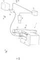
図1は、技能訓練システムの全体図を示す。
技能訓練システムは、訓練者である溶接士1の動きを計測して溶接する技能を訓練する。なお、訓練対象とする技能は、溶接だけでなく、ろう付け、塗装、グラインダ、磨き、鋳造などの任意の作業動作である。
溶接士1は、溶接対象物2を半自動溶接する作業者である。溶接士1は、把持するトーチ4の先端部である溶接ワイヤ4b(図5)からのアーク(発光)から目を守るために、顔に遮光面3を装着している。
溶接対象物2は、例えば2つの板状の母材である。これらの母材間を溶接ワイヤ4bからアークの発熱により溶け出した溶接材で接続することで、2つの母材が1つの金属板のように接合される。FIG. 1 shows an overall view of the skill training system.
The skill training system trains the skill of welding by measuring the movement of the welder 1 as a trainee. The skills to be trained include not only welding but also any work operation such as brazing, painting, grinder, polishing, casting, and the like.
The welder 1 is an operator who semi-automatically welds the welding target 2. The welder 1 wears a light-shielding surface 3 on his / her face in order to protect his eyes from an arc (light emission) from a
The welding target 2 is, for example, two plate-shaped base materials. By connecting these base materials with a welding material that has melted out of the
図1に示す溶接の作業現場には、溶接用の機材に加え、技能訓練用の機材が配備されている。
制御装置(技能訓練装置)11は、各計測装置(視野映像用カメラ15、マーカ計測用カメラ14と、電気計測装置12)に接続され、各計測装置の動作を制御する。なお、制御装置11と5台のマーカ計測用カメラ14との間の通信ケーブルを図示省略したが、制御装置11と各マーカ計測用カメラ14との間の通信手段は、無線通信でもよいし、有線通信でもよい。
半自動溶接電源5は、トーチ4に溶接用の電力を供給する。電気計測装置12は、半自動溶接電源5が供給する電力として、溶接電流・溶接電圧を計測する。At the welding work site shown in FIG. 1, equipment for skill training is provided in addition to equipment for welding.
The control device (skill training device) 11 is connected to each of the measuring devices (the visual
The semi-automatic welding power supply 5 supplies electric power for welding to the
マーカ計測用カメラ14は、溶接士1および溶接対象物2の周囲に配置されている。マーカ計測用カメラ14は、作業現場内の各所に配置されているマーカ13を撮影し、その撮影画像からモーションキャプチャによりマーカ13の各位置を取得する。このマーカ13は、例えば、溶接士1、遮光面3、トーチ4、溶接対象物2などに貼り付けられている(図示では球形)。 The
視野映像用カメラ15は、溶接士1から見た溶接中の視野を撮影するためのカメラである。図1では、視野映像用カメラ15の視野の一例として、溶接士1の背後の撮影位置から溶接士1の前方を撮影範囲とするような位置に配置した。
なお、溶接対象物2が大きく、溶接中に作業者の視野が移動する場合には、視野映像用カメラ15も追従して移動するほうがよい。または溶接士1の身体の一部に(例えば遮光面3に)、視野映像用カメラ15を取り付けてもよい。The visual
When the welding target 2 is large and the field of view of the worker moves during welding, it is preferable that the
以上説明した図1の技能訓練システムは、実際にアーク光を出して溶接訓練する現場での実地訓練を想定した。一方、バーチャル訓練システムにおいても同様の機能を搭載することが可能である。そのときには、溶接士1は、顔に遮光面3を装着する代わりに、ヘッドマウントディスプレイを装着する。
そして、ヘッドマウントディスプレイに搭載されたジャイロセンサなどから溶接士1の動作情報を計測することとしてもよい。さらに、訓練動作に合わせた技能の状態を、ヘッドマウントディプレイ上に模擬的に表示してもよい。The skill training system of FIG. 1 described above is assumed to be an on-the-spot training where welding arc training is actually performed by emitting arc light. On the other hand, a virtual training system can be equipped with the same function. At that time, the welder 1 wears a head-mounted display instead of mounting the light shielding surface 3 on the face.
Then, the operation information of the welder 1 may be measured from a gyro sensor or the like mounted on the head mounted display. Further, the state of the skill in accordance with the training operation may be simulated and displayed on the head mounted display.
図2は、制御装置11の詳細を示す構成図である。
制御装置11は、CPU(Central Processing Unit)と、メモリと、ハードディスクなどの記憶手段(記憶部)と、ネットワークインタフェースとを有するコンピュータとして構成される。
このコンピュータは、CPUが、メモリ上に読み込んだプログラム(アプリケーションや、その略のアプリとも呼ばれる)を実行することにより、各処理部により構成される制御部(制御手段)を動作させる。FIG. 2 is a configuration diagram showing details of the
The
In this computer, a CPU executes a program (also called an application or an abbreviation for an application) read into a memory, thereby operating a control unit (control unit) including each processing unit.
制御装置11は、視野映像取得部21と、映像データ格納部22と、空間位置対応部23と、計測装置制御部31と、計測データ格納部32と、動作情報検知部33と、動作判定部34と、報知部35と、格納部40とを有する。格納部40には、適正範囲格納部41と、関連知識格納部42と、動作姿勢関係情報格納部43とが対応付けられた動作判断指標情報が格納されている。 The
視野映像取得部21は、視野映像用カメラ15の計測データである溶接士1の視野映像を取得し、映像データ格納部22に記憶する。
計測装置制御部31は、各計測装置から以下に例示する計測データを受信し、蓄積データとして計測データ格納部32に記憶する。
・マーカ計測用カメラ14によるトーチ4の計測データとして、トーチ4の高さ、トーチ4の角度、トーチ4を持つひじの角度
・マーカ計測用カメラ14による溶接ワイヤ4bの計測データとして、平均移動速度、ウィービング条件、溶加材の供給量
・マーカ計測用カメラ14による遮光面3の計測データとして、溶接士1の頭の位置など
・電気計測装置12の計測データとして、電流値、電圧値などの溶接条件データ
なお、計測センサによる計測データは、視覚情報(映像)に限定されず、聴覚情報(音)、触覚情報(熱、圧力)も扱ってもよい。The visual field
The measurement
The height of the
空間位置対応部23は、映像データ格納部22の視野映像データと、その視野内における計測データ格納部32の計測データとで、互いの空間位置(3次元位置)を対応付ける。この対応付け処理により、映像データ格納部22の視野映像データと、その視野内における計測データ格納部32の計測データとで、ある対象物が、同じ時刻に同じ場所に存在することがわかる。これにより、ウィービング幅などの計測データを視野映像データに合成表示できる。 The spatial
動作情報検知部33は、計測データ格納部32の計測データをもとに、溶接士1の動作情報を検知する。動作情報検知部33は、例えば、マーカ13を用いたモーションキャプチャ、加速度・角速度・地磁気計測装置、全地球測位システム(GPS:Global Positioning System)、屋内全地球測位システム(屋内GPS)、ステレオカメラとして実現される。なお、動作情報検知部33は、視野映像取得部21が同期して作動することで、溶接士1の動作と溶接士1の視野映像とを対応付けることができる。
動作判定部34は、動作情報検知部33の動作情報と、適正範囲格納部41の適正範囲とをもとに、報知部35に出力させる関連知識格納部42の関連知識、動作姿勢関係情報格納部43の動作姿勢関係情報を決定する。The operation
Based on the operation information of the operation
適正範囲格納部41の適正範囲とは、例えば、アークを発しながら溶接対象物2上を移動するトーチ4の溶接ワイヤ4bの移動範囲である(詳細は図6の適正範囲85を参照)。
関連知識格納部42には、技能の品質に関するノウハウ、理屈、理論、過去事例、動作判断の着眼点などが格納されている。動作判断の着眼点については、動作を判断するための目安やヒントとなっている。例えば、溶接時のウィービング幅の見極め方として、「ワイヤと開先の位置が一致するところまで、ウィービングする」(詳細は図7)などの溶接知識が関連知識格納部42に格納される。The appropriate range of the appropriate
The related
動作姿勢関係情報格納部43には、溶接士1がある動作を実行するために適切な姿勢をデータ化したものが格納されている。安定した模範姿勢や、疲労が少ない模範姿勢などの適正な姿勢データが、事前に動作姿勢関係情報格納部43に登録されている。姿勢データのパラメータとして、例えば、溶接時のウィービング動作では、頭の位置や角度、腕の位置や角度、ひじの位置や角度、腰の位置や角度、足の位置や角度などが重要である。 The operation posture relation
報知部35は、動作判定部34が決定した動作情報に関連する関連知識と、動作姿勢関係情報とを、画面表示や音声出力などで溶接士1などのユーザへ報知する。ここでの報知されるユーザとは、訓練者である溶接士1本人に限定されず、溶接士1と同じ作業場にいる他の作業員やその監督者、作業場とは別室にいる訓練聴講者なども該当する。
なお、報知部35は、これらの報知する情報について、さらに、空間位置対応部23において対応付けられた視野映像データも合成して報知してもよい。つまり、溶接士1の視野映像中に、格納部40の各情報(適正範囲、関連知識、動作姿勢関係情報)が合成されて表示される。
これにより、溶接士1などのユーザは、リアルタイムに合成された改善提案を確認することで、すぐに適切な作業に修正できる。つまり、溶接士1の動作が連続的に変化した場合でも、前記の合成表示を溶接士1などのユーザに見せることにより、動作判断の着眼点や適正範囲などを容易に把握させることができる。なお、合成表示の出力先は、訓練者が装着しているヘッドマウントディスプレイとしてもよい。The
The notifying
Thereby, the user such as the welder 1 can immediately correct the work by checking the improvement proposal synthesized in real time. In other words, even when the operation of the welder 1 changes continuously, the point of view of the operation determination and the appropriate range can be easily grasped by showing the synthesized display to the user such as the welder 1. The output destination of the composite display may be a head mounted display worn by the trainee.
以上、図1,図2をもとに、技能訓練システムの概要を説明した。以下、図3〜図7を参照して、実際の溶接現場において技能訓練システムが溶接士1を支援する具体例を説明する。
図3は、溶接される前の溶接対象物2を示す斜視図である。
図4は、溶接された後の溶接対象物2を示す斜視図である。
溶接対象物2は、左側の母材89aと、右側の母材89bとの組み合わせである。母材89aのX軸+方向の端部である突合せ部83aと、母材89bのX軸−方向の端部である突合せ部83bとが互いに突合せ部83として密着する。
そして、母材89aのZ軸+方向の開先端部82aと、母材89bのZ軸+方向の開先端部82bとは母材間が密着した状態でも距離が空いている。この距離の空間に対して溶接材であるビード88が流し込まれることで、2つの母材が溶接される。The outline of the skill training system has been described above with reference to FIGS. Hereinafter, a specific example in which the skill training system supports the welder 1 at an actual welding site will be described with reference to FIGS.
FIG. 3 is a perspective view showing the welding target 2 before welding.
FIG. 4 is a perspective view showing the welding target 2 after welding.
The welding target 2 is a combination of the
The
図5は、図4の母材89a,89bを上部(Z軸+方向)から見下ろした平面図である。溶接士1は、Y軸+方向から蛇行(ウィービング)しながらY軸−方向に向かうようにトーチ4の溶接ワイヤ4bを移動させる。この溶接ワイヤ4bの先端部のウィービング軌跡を、矢印で図示した。ウィービング軌跡は、折り返し点P1,P2,P3で示すように、移動途中で3箇所折り返している。
ウィービング幅TWを、ウィービング軌跡のうちのX軸−方向の最小値(つまり折り返し点P1,P3)から、X軸+方向の最大値(つまり折り返し点P2)までの幅として定義する。
動作情報検知部33は、トーチ4に付されたマーカ13の計測データなどを参照して、ウィービング軌跡と、ウィービング幅TWとを追跡する。FIG. 5 is a plan view of the
The weaving width TW is defined as the width of the weaving locus from the minimum value in the negative X-axis direction (that is, the turning points P1 and P3) to the maximum value in the positive X-axis direction (that is, the turning point P2).
The operation
図6は、図5の平面図において、事前に適正範囲格納部41に登録されている適正範囲を示す平面図である。
適正範囲85は、溶接対象物2に溶接材を注入させる溶接範囲であり、開先端部82a〜開先端部82bのX軸幅と、母材89a,89bのY軸長さとをもとにした略長方形として登録される。つまり、この適正範囲85内に溶接ワイヤ4bのビード88を流し込めるように、ウィービング軌跡を溶接士1に形成させることが、適正な作業といえる。
一方、適正範囲85のX軸幅を図6よりも突合せ部83側に狭く設定することで、ウィービング軌跡が開先端部82aまたは開先端部82bをまたぐ前に、関連知識を表示させることもできる。FIG. 6 is a plan view showing a proper range registered in the proper
The
On the other hand, by setting the X-axis width of the
図7は、図6の平面図で定義された適正範囲85をもとに、関連知識を表示した画面例である。
表示ディスプレイ80には、図5と同様に、動作情報検知部33が検知したウィービング軌跡が、蛇行する矢印として表示されている。しかし、図7では第2折り返し地点P2が、適正範囲85の外側にはみ出してしまった。
ここで、動作判定部34は、ウィービング軌跡が適正範囲85を外れたことを検知する。そして、報知部35は、その適正範囲85に対応する関連知識格納部42の関連知識として、「ワイヤと開先の位置が一致するところまで、ウィービングする」旨の関連知識表示81を表示する。換言すると、ウィービング軌跡が適正範囲85を外れるまでは、適正な作業が行われているので、関連知識表示81の表示を省略してもよい。
さらに、関連知識表示81には、関連知識の内容を示す文字列に加え、図7の折り返し点P2を指す矢印のように、どの部分で関連知識が適用されるかを示す位置情報も併せて表示してもよい。FIG. 7 is an example of a screen displaying related knowledge based on the
As in FIG. 5, the weaving locus detected by the motion
Here, the
Further, in the
また、動作判定部34は、ウィービング軌跡が適正範囲85を外れたときに、そのウィービング軌跡を行ったときの溶接士1の姿勢についても判定してもよい。
例えば、ウィービング動作時の模範姿勢として、「ひじの高さが肩の高さから15cm下」である姿勢とし、「ひじの高さが肩の高さから15cm下±5cmの範囲」を適正範囲格納部41の姿勢適正範囲として、事前に登録しておく。そして、動作判定部34は、溶接士1の姿勢が姿勢適正範囲から外れた場合には、模範姿勢との差分情報などを改善提案として、報知部35を介して溶接士1に報知することができる。In addition, when the weaving locus deviates from the
For example, as the model posture during weaving operation, the posture where "the elbow height is 15 cm below the shoulder height" and the "elbow height is 15 cm below the shoulder height ± 5 cm" is the appropriate range It is registered in advance as an appropriate posture range of the
以上説明した本実施形態では、動作判定部34が動作情報検知部33の動作情報と、適正範囲格納部41の適正範囲とをもとに、報知部35に出力させる関連知識格納部42の関連知識、動作姿勢関係情報格納部43の動作姿勢関係情報を決定する。
これにより、溶接士1の現在の動作についての適切な関連知識をタイミングよく提示させることで、未習得のノウハウを本質的に理解させることができる。
さらに、報知部35が出力する関連知識を、視野映像用カメラ15の視野映像と合成することにより、図7に示したようなウィービングの折り返し地点などの適正範囲85と、その関連知識表示81とを関連知識とを、3次元空間座標を使ってタイミングをよく、的確な位置で表示することができる。In the present embodiment described above, the
Thus, by presenting appropriate relevant knowledge about the current operation of the welder 1 in a timely manner, it is possible to make the unlearned know-how essentially understood.
Further, by synthesizing the relevant knowledge output by the
なお、本発明は前記した実施例に限定されるものではなく、様々な変形例が含まれる。例えば、前記した実施例は本発明を分かりやすく説明するために詳細に説明したものであり、必ずしも説明した全ての構成を備えるものに限定されるものではない。
また、ある実施例の構成の一部を他の実施例の構成に置き換えることが可能であり、また、ある実施例の構成に他の実施例の構成を加えることも可能である。
また、各実施例の構成の一部について、他の構成の追加・削除・置換をすることが可能である。また、上記の各構成、機能、処理部、処理手段などは、それらの一部または全部を、例えば集積回路で設計するなどによりハードウェアで実現してもよい。
また、前記の各構成、機能などは、プロセッサがそれぞれの機能を実現するプログラムを解釈し、実行することによりソフトウェアで実現してもよい。Note that the present invention is not limited to the above-described embodiment, and includes various modifications. For example, the above-described embodiment has been described in detail in order to explain the present invention in an easy-to-understand manner, and is not necessarily limited to one having all the described configurations.
Further, a part of the configuration of one embodiment can be replaced with the configuration of another embodiment, and the configuration of one embodiment can be added to the configuration of another embodiment.
Further, for a part of the configuration of each embodiment, it is possible to add, delete, or replace another configuration. In addition, each of the above-described configurations, functions, processing units, processing means, and the like may be partially or entirely realized by hardware by, for example, designing an integrated circuit.
In addition, the above-described configurations, functions, and the like may be implemented by software by a processor interpreting and executing a program that implements each function.
各機能を実現するプログラム、テーブル、ファイルなどの情報は、メモリや、ハードディスク、SSD(Solid State Drive)などの記録装置、または、IC(Integrated Circuit)カード、SDカード、DVD(Digital Versatile Disc)などの記録媒体に置くことができる。
また、制御線や情報線は説明上必要と考えられるものを示しており、製品上必ずしも全ての制御線や情報線を示しているとは限らない。実際にはほとんど全ての構成が相互に接続されていると考えてもよい。
さらに、各装置を繋ぐ通信手段は、無線LANに限定せず、有線LANやその他の通信手段に変更してもよい。Information such as programs, tables, and files that realize each function is stored in a memory, hard disk, recording device such as SSD (Solid State Drive), IC (Integrated Circuit) card, SD card, DVD (Digital Versatile Disc), etc. Recording media.
In addition, control lines and information lines are shown as necessary for the description, and do not necessarily indicate all control lines and information lines on a product. In fact, almost all components may be considered to be interconnected.
Further, the communication means for connecting the devices is not limited to the wireless LAN, but may be changed to a wired LAN or other communication means.
1 溶接士
2 溶接対象物
3 遮光面
4 トーチ
4b 溶接ワイヤ
5 半自動溶接電源
11 制御装置(技能訓練装置)
12 電気計測装置
13 マーカ
14 マーカ計測用カメラ
15 視野映像用カメラ
21 視野映像取得部
22 映像データ格納部
23 空間位置対応部
31 計測装置制御部
32 計測データ格納部
33 動作情報検知部
34 動作判定部
35 報知部
40 格納部
41 適正範囲格納部
42 関連知識格納部
43 動作姿勢関係情報格納部
80 表示ディスプレイ
81 関連知識表示
82 開先端部
83 突合せ部
85 適正範囲
88 ビード
89 母材DESCRIPTION OF SYMBOLS 1 Welder 2 Welding object 3
Claims (6)
Translated fromJapanese訓練者の動作を計測した結果である動作情報を検知する動作情報検知部と、
前記動作情報検知部で検知された前記動作情報が前記格納部の前記適正範囲から外れたか否かを判定する動作判定部と、
前記動作判定部により前記適正範囲から外れたと判定された動作情報に対して、その外れた適正範囲に対応づけられている前記関連知識を前記格納部から取得して報知する報知部とを有することを特徴とする
技能訓練装置。A storage unit for storing an operation determination index information in which an appropriate range in which the operation of the work is performed and the related knowledge about the appropriate range,
An operation information detection unit that detects operation information that is a result of measuring the operation of the trainee,
An operation determination unit that determines whether the operation information detected by the operation information detection unit is out of the appropriate range of the storage unit,
A notification unit that obtains, from the storage unit, the related knowledge that is associated with the out-of-appropriate range for the operation information determined to be out of the appropriate range by the operation determination unit, and notifies the notification unit. A skill training device characterized by the following.
前記報知部は、前記外れた適正範囲に対応づけられている前記関連知識を報知するときに、前記外れた適正範囲に対応づけられている前記姿勢情報も併せて報知することを特徴とする
請求項1に記載の技能訓練装置。The motion determination index information stored in the storage unit is further associated with posture information when a work operation is performed,
The notifying unit, when notifying the related knowledge associated with the deviated appropriate range, also notifies the posture information associated with the deviated appropriate range. Item 2. The skill training device according to Item 1.
請求項1に記載の技能訓練装置。The notifying unit, when notifying the related knowledge associated with the deviated appropriate range, notifies a combined display of the visual field image of the trainee during operation and the related knowledge. The skill training device according to claim 1.
請求項3に記載の技能訓練装置。The skill training device according to claim 3, wherein the notification unit sets the output destination of the combined display to a head-mounted display worn by the trainee.
前記動作判定部は、前記訓練者が把持する溶接器具が前記溶接範囲から外れたときに、前記溶接知識を報知するように前記報知部を制御することを特徴とする
請求項1ないし請求項4のいずれか1項に記載の技能訓練装置。In the storage unit, a welding range in which a welding material is injected into a welding target is defined as the appropriate range in which a work operation is performed, and as the related knowledge corresponding to the welding range, a trajectory of a welding tool is the welding range. Welding knowledge to move within the range is defined,
The said operation determination part controls the said alerting | reporting part so that it may alert | report the welding knowledge, when the welding tool which the said trainee grips is out of the said welding range, The Claims 1 thru | or 4 characterized by the above-mentioned. The skill training device according to any one of the above.
前記格納部には、作業の動作が行われる適正範囲と、その適正範囲についての関連知識とを対応付けた動作判断指標情報が格納され、
前記動作情報検知部は、訓練者の動作を計測した結果である動作情報を検知し、
前記動作判定部は、前記動作情報検知部で検知された前記動作情報が前記格納部の前記適正範囲から外れたか否かを判定し、
前記報知部は、前記動作判定部により前記適正範囲から外れたと判定された動作情報に対して、その外れた適正範囲に対応づけられている前記関連知識を前記格納部から取得して報知することを特徴とする
技能訓練方法。The skill training device has a storage unit, an operation information detection unit, an operation determination unit, and a notification unit,
The storage unit stores an operation determination index information in which an appropriate range in which the operation of the work is performed and the related knowledge about the appropriate range are stored,
The motion information detection unit detects motion information that is a result of measuring the motion of the trainee,
The operation determination unit determines whether the operation information detected by the operation information detection unit is out of the appropriate range of the storage unit,
The notifying unit, for the operation information determined to be out of the appropriate range by the operation determining unit, acquires from the storage unit and notifies the related knowledge associated with the out of the appropriate range. A skill training method characterized by the following.
Priority Applications (3)
| Application Number | Priority Date | Filing Date | Title |
|---|---|---|---|
| JP2018132911AJP2020012858A (en) | 2018-07-13 | 2018-07-13 | Skill training device and skill training method |
| US17/258,301US11393360B2 (en) | 2018-07-13 | 2019-03-04 | Skill training device and skill training method |
| PCT/JP2019/008315WO2020012701A1 (en) | 2018-07-13 | 2019-03-04 | Skill training device and skill training method |
Applications Claiming Priority (1)
| Application Number | Priority Date | Filing Date | Title |
|---|---|---|---|
| JP2018132911AJP2020012858A (en) | 2018-07-13 | 2018-07-13 | Skill training device and skill training method |
Publications (1)
| Publication Number | Publication Date |
|---|---|
| JP2020012858Atrue JP2020012858A (en) | 2020-01-23 |
Family
ID=69141345
Family Applications (1)
| Application Number | Title | Priority Date | Filing Date |
|---|---|---|---|
| JP2018132911APendingJP2020012858A (en) | 2018-07-13 | 2018-07-13 | Skill training device and skill training method |
Country Status (3)
| Country | Link |
|---|---|
| US (1) | US11393360B2 (en) |
| JP (1) | JP2020012858A (en) |
| WO (1) | WO2020012701A1 (en) |
Cited By (1)
| Publication number | Priority date | Publication date | Assignee | Title |
|---|---|---|---|---|
| WO2021241558A1 (en)* | 2020-05-26 | 2021-12-02 | 国立大学法人 東京大学 | System and operation method |
Families Citing this family (1)
| Publication number | Priority date | Publication date | Assignee | Title |
|---|---|---|---|---|
| JP7261682B2 (en)* | 2019-07-17 | 2023-04-20 | 株式会社日立製作所 | Welding work data storage device, welding work support system and welding robot control device |
Citations (8)
| Publication number | Priority date | Publication date | Assignee | Title |
|---|---|---|---|---|
| JPH11344922A (en)* | 1998-06-01 | 1999-12-14 | Osaka Gas Co Ltd | Visual field information display |
| JP2002107797A (en)* | 2000-09-27 | 2002-04-10 | Olympus Optical Co Ltd | Picture advice system |
| JP2005134536A (en)* | 2003-10-29 | 2005-05-26 | Omron Corp | Work training support system |
| JP2012218058A (en)* | 2011-04-13 | 2012-11-12 | Sumitomo Heavy Industries Marine & Engineering Co Ltd | Welding simulator |
| EP2801966A1 (en)* | 2012-09-19 | 2014-11-12 | Dulin Laszlo | Method for simulating welding |
| US20160207134A1 (en)* | 2015-01-20 | 2016-07-21 | Illinois Tool Works Inc. | Weld output control by a welding vision system |
| WO2016162952A1 (en)* | 2015-04-07 | 2016-10-13 | 三菱電機株式会社 | Air conditioner maintenance support system |
| JP2018081093A (en)* | 2016-11-07 | 2018-05-24 | リンカーン グローバル,インコーポレイテッド | System and method for calibrating welding training apparatus |
Family Cites Families (9)
| Publication number | Priority date | Publication date | Assignee | Title |
|---|---|---|---|---|
| JP2001171140A (en) | 1999-12-17 | 2001-06-26 | Copyer Co Ltd | Ink-jet recording apparatus |
| JP4385860B2 (en) | 2004-06-23 | 2009-12-16 | カシオ計算機株式会社 | Performance learning apparatus and performance learning program |
| JP4963094B2 (en) | 2007-09-11 | 2012-06-27 | 独立行政法人産業技術総合研究所 | Work support device |
| JP5921898B2 (en) | 2012-01-30 | 2016-05-24 | ジャパンマリンユナイテッド株式会社 | Welding skill education support device |
| US9583014B2 (en) | 2012-11-09 | 2017-02-28 | Illinois Tool Works Inc. | System and device for welding training |
| JP2015225214A (en) | 2014-05-28 | 2015-12-14 | 旭エレクトロニクス株式会社 | Simulation system |
| WO2016144744A1 (en)* | 2015-03-09 | 2016-09-15 | Illinois Tool Works Inc. | Methods and apparatus to provide visual information associated with welding operations |
| US10839717B2 (en)* | 2016-01-11 | 2020-11-17 | Illinois Tool Works Inc. | Weld training systems to synchronize weld data for presentation |
| JP2018010310A (en) | 2017-08-24 | 2018-01-18 | ソニー株式会社 | Program, information processing device and information processing method |
- 2018
- 2018-07-13JPJP2018132911Apatent/JP2020012858A/enactivePending
- 2019
- 2019-03-04USUS17/258,301patent/US11393360B2/enactiveActive
- 2019-03-04WOPCT/JP2019/008315patent/WO2020012701A1/ennot_activeCeased
Patent Citations (8)
| Publication number | Priority date | Publication date | Assignee | Title |
|---|---|---|---|---|
| JPH11344922A (en)* | 1998-06-01 | 1999-12-14 | Osaka Gas Co Ltd | Visual field information display |
| JP2002107797A (en)* | 2000-09-27 | 2002-04-10 | Olympus Optical Co Ltd | Picture advice system |
| JP2005134536A (en)* | 2003-10-29 | 2005-05-26 | Omron Corp | Work training support system |
| JP2012218058A (en)* | 2011-04-13 | 2012-11-12 | Sumitomo Heavy Industries Marine & Engineering Co Ltd | Welding simulator |
| EP2801966A1 (en)* | 2012-09-19 | 2014-11-12 | Dulin Laszlo | Method for simulating welding |
| US20160207134A1 (en)* | 2015-01-20 | 2016-07-21 | Illinois Tool Works Inc. | Weld output control by a welding vision system |
| WO2016162952A1 (en)* | 2015-04-07 | 2016-10-13 | 三菱電機株式会社 | Air conditioner maintenance support system |
| JP2018081093A (en)* | 2016-11-07 | 2018-05-24 | リンカーン グローバル,インコーポレイテッド | System and method for calibrating welding training apparatus |
Cited By (3)
| Publication number | Priority date | Publication date | Assignee | Title |
|---|---|---|---|---|
| WO2021241558A1 (en)* | 2020-05-26 | 2021-12-02 | 国立大学法人 東京大学 | System and operation method |
| JP2021189223A (en)* | 2020-05-26 | 2021-12-13 | 国立大学法人 東京大学 | System and operation method |
| JP7351523B2 (en) | 2020-05-26 | 2023-09-27 | 国立大学法人 東京大学 | System and operating method |
Also Published As
| Publication number | Publication date |
|---|---|
| WO2020012701A1 (en) | 2020-01-16 |
| US20210142693A1 (en) | 2021-05-13 |
| US11393360B2 (en) | 2022-07-19 |
Similar Documents
| Publication | Publication Date | Title |
|---|---|---|
| JP7125872B2 (en) | Work support device and work support method | |
| US11670191B2 (en) | Systems and methods to provide weld training | |
| CN108713223B (en) | System and method for providing welding training | |
| CN105745696B (en) | A system and method for a welding training system | |
| CN107000099B (en) | Welding training system and method | |
| US10417935B2 (en) | System and device for welding training | |
| US9368045B2 (en) | System and device for welding training | |
| JP5062774B2 (en) | Work training system, work training method, and recording medium recording the work training method | |
| US20230041258A1 (en) | Welding Control Device, Welding Robot System, and Welding Control Method | |
| JP4932048B1 (en) | Work support system | |
| CN114939706A (en) | Mask-based welding tracking system | |
| JP2020106574A (en) | Work support device and work support method | |
| CN116586727A (en) | Calibration procedure for mask-based welding tracking system | |
| CN114939707A (en) | Welding tracking system | |
| US11393360B2 (en) | Skill training device and skill training method | |
| US20200139214A1 (en) | Swing Measurement Device, Swing Measurement Method, and Swing Measurement Program | |
| JP5921898B2 (en) | Welding skill education support device | |
| WO2020246425A1 (en) | Video processing method, video processing device, and recording medium having video processing program recorded therein | |
| JP2023156237A (en) | Processing apparatus, processing system, head-worn display, processing method, program, and storage medium | |
| JP2025004379A (en) | Training support system, training support method, and program | |
| JP2025066484A (en) | Maintenance training support device, maintenance training support system, maintenance training support method and program |
Legal Events
| Date | Code | Title | Description |
|---|---|---|---|
| A621 | Written request for application examination | Free format text:JAPANESE INTERMEDIATE CODE: A621 Effective date:20210318 | |
| A131 | Notification of reasons for refusal | Free format text:JAPANESE INTERMEDIATE CODE: A131 Effective date:20220405 | |
| A521 | Request for written amendment filed | Free format text:JAPANESE INTERMEDIATE CODE: A523 Effective date:20220513 | |
| A131 | Notification of reasons for refusal | Free format text:JAPANESE INTERMEDIATE CODE: A131 Effective date:20220927 | |
| A521 | Request for written amendment filed | Free format text:JAPANESE INTERMEDIATE CODE: A523 Effective date:20221107 | |
| A02 | Decision of refusal | Free format text:JAPANESE INTERMEDIATE CODE: A02 Effective date:20230307 |