JP2020011299A - Method of coating workpiece, use of workpiece, coating machine, and use of friction welding equipment - Google Patents
Method of coating workpiece, use of workpiece, coating machine, and use of friction welding equipmentDownload PDFInfo
- Publication number
- JP2020011299A JP2020011299AJP2019131538AJP2019131538AJP2020011299AJP 2020011299 AJP2020011299 AJP 2020011299AJP 2019131538 AJP2019131538 AJP 2019131538AJP 2019131538 AJP2019131538 AJP 2019131538AJP 2020011299 AJP2020011299 AJP 2020011299A
- Authority
- JP
- Japan
- Prior art keywords
- workpiece
- coating
- coating material
- friction
- friction body
- Prior art date
- Legal status (The legal status is an assumption and is not a legal conclusion. Google has not performed a legal analysis and makes no representation as to the accuracy of the status listed.)
- Granted
Links
Images


Classifications
- B—PERFORMING OPERATIONS; TRANSPORTING
- B23—MACHINE TOOLS; METAL-WORKING NOT OTHERWISE PROVIDED FOR
- B23K—SOLDERING OR UNSOLDERING; WELDING; CLADDING OR PLATING BY SOLDERING OR WELDING; CUTTING BY APPLYING HEAT LOCALLY, e.g. FLAME CUTTING; WORKING BY LASER BEAM
- B23K20/00—Non-electric welding by applying impact or other pressure, with or without the application of heat, e.g. cladding or plating
- B23K20/12—Non-electric welding by applying impact or other pressure, with or without the application of heat, e.g. cladding or plating the heat being generated by friction; Friction welding
- B—PERFORMING OPERATIONS; TRANSPORTING
- B23—MACHINE TOOLS; METAL-WORKING NOT OTHERWISE PROVIDED FOR
- B23K—SOLDERING OR UNSOLDERING; WELDING; CLADDING OR PLATING BY SOLDERING OR WELDING; CUTTING BY APPLYING HEAT LOCALLY, e.g. FLAME CUTTING; WORKING BY LASER BEAM
- B23K1/00—Soldering, e.g. brazing, or unsoldering
- B23K1/20—Preliminary treatment of work or areas to be soldered, e.g. in respect of a galvanic coating
- B—PERFORMING OPERATIONS; TRANSPORTING
- B23—MACHINE TOOLS; METAL-WORKING NOT OTHERWISE PROVIDED FOR
- B23K—SOLDERING OR UNSOLDERING; WELDING; CLADDING OR PLATING BY SOLDERING OR WELDING; CUTTING BY APPLYING HEAT LOCALLY, e.g. FLAME CUTTING; WORKING BY LASER BEAM
- B23K20/00—Non-electric welding by applying impact or other pressure, with or without the application of heat, e.g. cladding or plating
- B23K20/12—Non-electric welding by applying impact or other pressure, with or without the application of heat, e.g. cladding or plating the heat being generated by friction; Friction welding
- B23K20/1215—Non-electric welding by applying impact or other pressure, with or without the application of heat, e.g. cladding or plating the heat being generated by friction; Friction welding for other purposes than joining, e.g. built-up welding
- B—PERFORMING OPERATIONS; TRANSPORTING
- B23—MACHINE TOOLS; METAL-WORKING NOT OTHERWISE PROVIDED FOR
- B23K—SOLDERING OR UNSOLDERING; WELDING; CLADDING OR PLATING BY SOLDERING OR WELDING; CUTTING BY APPLYING HEAT LOCALLY, e.g. FLAME CUTTING; WORKING BY LASER BEAM
- B23K20/00—Non-electric welding by applying impact or other pressure, with or without the application of heat, e.g. cladding or plating
- B23K20/12—Non-electric welding by applying impact or other pressure, with or without the application of heat, e.g. cladding or plating the heat being generated by friction; Friction welding
- B23K20/122—Non-electric welding by applying impact or other pressure, with or without the application of heat, e.g. cladding or plating the heat being generated by friction; Friction welding using a non-consumable tool, e.g. friction stir welding
- B23K20/128—Non-electric welding by applying impact or other pressure, with or without the application of heat, e.g. cladding or plating the heat being generated by friction; Friction welding using a non-consumable tool, e.g. friction stir welding making use of additional material
- B—PERFORMING OPERATIONS; TRANSPORTING
- B23—MACHINE TOOLS; METAL-WORKING NOT OTHERWISE PROVIDED FOR
- B23K—SOLDERING OR UNSOLDERING; WELDING; CLADDING OR PLATING BY SOLDERING OR WELDING; CUTTING BY APPLYING HEAT LOCALLY, e.g. FLAME CUTTING; WORKING BY LASER BEAM
- B23K20/00—Non-electric welding by applying impact or other pressure, with or without the application of heat, e.g. cladding or plating
- B23K20/12—Non-electric welding by applying impact or other pressure, with or without the application of heat, e.g. cladding or plating the heat being generated by friction; Friction welding
- B23K20/129—Non-electric welding by applying impact or other pressure, with or without the application of heat, e.g. cladding or plating the heat being generated by friction; Friction welding specially adapted for particular articles or workpieces
- B—PERFORMING OPERATIONS; TRANSPORTING
- B23—MACHINE TOOLS; METAL-WORKING NOT OTHERWISE PROVIDED FOR
- B23K—SOLDERING OR UNSOLDERING; WELDING; CLADDING OR PLATING BY SOLDERING OR WELDING; CUTTING BY APPLYING HEAT LOCALLY, e.g. FLAME CUTTING; WORKING BY LASER BEAM
- B23K35/00—Rods, electrodes, materials, or media, for use in soldering, welding, or cutting
- B23K35/02—Rods, electrodes, materials, or media, for use in soldering, welding, or cutting characterised by mechanical features, e.g. shape
- B23K35/0222—Rods, electrodes, materials, or media, for use in soldering, welding, or cutting characterised by mechanical features, e.g. shape for use in soldering, brazing
- B23K35/0233—Sheets, foils
- B—PERFORMING OPERATIONS; TRANSPORTING
- B23—MACHINE TOOLS; METAL-WORKING NOT OTHERWISE PROVIDED FOR
- B23K—SOLDERING OR UNSOLDERING; WELDING; CLADDING OR PLATING BY SOLDERING OR WELDING; CUTTING BY APPLYING HEAT LOCALLY, e.g. FLAME CUTTING; WORKING BY LASER BEAM
- B23K35/00—Rods, electrodes, materials, or media, for use in soldering, welding, or cutting
- B23K35/02—Rods, electrodes, materials, or media, for use in soldering, welding, or cutting characterised by mechanical features, e.g. shape
- B23K35/0222—Rods, electrodes, materials, or media, for use in soldering, welding, or cutting characterised by mechanical features, e.g. shape for use in soldering, brazing
- B23K35/0244—Powders, particles or spheres; Preforms made therefrom
- B—PERFORMING OPERATIONS; TRANSPORTING
- B23—MACHINE TOOLS; METAL-WORKING NOT OTHERWISE PROVIDED FOR
- B23K—SOLDERING OR UNSOLDERING; WELDING; CLADDING OR PLATING BY SOLDERING OR WELDING; CUTTING BY APPLYING HEAT LOCALLY, e.g. FLAME CUTTING; WORKING BY LASER BEAM
- B23K35/00—Rods, electrodes, materials, or media, for use in soldering, welding, or cutting
- B23K35/02—Rods, electrodes, materials, or media, for use in soldering, welding, or cutting characterised by mechanical features, e.g. shape
- B23K35/0255—Rods, electrodes, materials, or media, for use in soldering, welding, or cutting characterised by mechanical features, e.g. shape for use in welding
- B23K35/0261—Rods, electrodes, wires
- B—PERFORMING OPERATIONS; TRANSPORTING
- B23—MACHINE TOOLS; METAL-WORKING NOT OTHERWISE PROVIDED FOR
- B23K—SOLDERING OR UNSOLDERING; WELDING; CLADDING OR PLATING BY SOLDERING OR WELDING; CUTTING BY APPLYING HEAT LOCALLY, e.g. FLAME CUTTING; WORKING BY LASER BEAM
- B23K2103/00—Materials to be soldered, welded or cut
- B23K2103/08—Non-ferrous metals or alloys
- B23K2103/10—Aluminium or alloys thereof
- B—PERFORMING OPERATIONS; TRANSPORTING
- B23—MACHINE TOOLS; METAL-WORKING NOT OTHERWISE PROVIDED FOR
- B23K—SOLDERING OR UNSOLDERING; WELDING; CLADDING OR PLATING BY SOLDERING OR WELDING; CUTTING BY APPLYING HEAT LOCALLY, e.g. FLAME CUTTING; WORKING BY LASER BEAM
- B23K2103/00—Materials to be soldered, welded or cut
- B23K2103/08—Non-ferrous metals or alloys
- B23K2103/12—Copper or alloys thereof
- B—PERFORMING OPERATIONS; TRANSPORTING
- B23—MACHINE TOOLS; METAL-WORKING NOT OTHERWISE PROVIDED FOR
- B23K—SOLDERING OR UNSOLDERING; WELDING; CLADDING OR PLATING BY SOLDERING OR WELDING; CUTTING BY APPLYING HEAT LOCALLY, e.g. FLAME CUTTING; WORKING BY LASER BEAM
- B23K2103/00—Materials to be soldered, welded or cut
- B23K2103/08—Non-ferrous metals or alloys
- B23K2103/14—Titanium or alloys thereof
- B—PERFORMING OPERATIONS; TRANSPORTING
- B23—MACHINE TOOLS; METAL-WORKING NOT OTHERWISE PROVIDED FOR
- B23K—SOLDERING OR UNSOLDERING; WELDING; CLADDING OR PLATING BY SOLDERING OR WELDING; CUTTING BY APPLYING HEAT LOCALLY, e.g. FLAME CUTTING; WORKING BY LASER BEAM
- B23K2103/00—Materials to be soldered, welded or cut
- B23K2103/08—Non-ferrous metals or alloys
- B23K2103/15—Magnesium or alloys thereof
Landscapes
- Engineering & Computer Science (AREA)
- Mechanical Engineering (AREA)
- Pressure Welding/Diffusion-Bonding (AREA)
- Other Surface Treatments For Metallic Materials (AREA)
Abstract
Translated fromJapaneseDescription
Translated fromJapanese本発明は、加工物を被覆する方法、加工物、被覆機械、および摩擦溶接装置の使用に関する。 The present invention relates to a method of coating a workpiece, a workpiece, a coating machine, and the use of a friction welding apparatus.
コンタクト素子を加工物に固定するために、たとえば超音波溶接方法を使用する取付けが知られている。溶接またははんだ付けによる接合も可能である。 Mounting is known for fixing the contact element to the workpiece, for example using an ultrasonic welding method. Joining by welding or soldering is also possible.
はんだ付けを用いた場合、いくつかの状況下では、たとえば化学物質によって加工物の表面を前処理する必要がある。これには労力を要する可能性がある。
本発明の問題は、加工物を被覆するためのより簡単な解決策を提供することである。With soldering, in some circumstances it is necessary to pre-treat the surface of the workpiece with, for example, chemicals. This can be labor intensive.
The problem of the present invention is to provide a simpler solution for coating a workpiece.
これは、本発明によれば、提供された被覆材料を加工物に摩擦溶接することによって解決される。 This is solved according to the invention by friction welding the provided coating material to the workpiece.
本発明による加工物の場合、本発明による方法を使用して提供された被覆が存在する。 In the case of a workpiece according to the invention, there is a coating provided using the method according to the invention.
本発明による被覆機械は、加工物を被覆する摩擦体が存在することを特徴とする。 The coating machine according to the invention is characterized in that there is a friction body for coating the workpiece.
本発明はまた、加工物を被覆する摩擦溶接装置の使用を想定する。 The present invention also contemplates the use of friction welding equipment to coat the workpiece.
本発明による解決策の場合、表面を前処理する必要はない。被覆材料は、高い圧力および摩擦によって加工物上へ押圧される。この方法中に生じる摩擦により、被覆材料は、材料の混合および拡散によって、加工物に接合される。本発明による被覆技法はまた、特に小さい領域の選択的な被覆に使用することができる。 With the solution according to the invention, it is not necessary to pretreat the surface. The coating material is pressed onto the workpiece by high pressure and friction. Due to the friction created during this process, the coating material is bonded to the workpiece by mixing and diffusion of the material. The coating technique according to the invention can also be used for the selective coating of particularly small areas.
本発明による解決策は、以下の構成およびさらなる展開によってさらに改善することができ、これらの構成および展開は、それ自体が各々有利であり、所望される場合は互いに組み合わせることもできる。 The solution according to the invention can be further improved by the following arrangements and further developments, which are each advantageous in themselves and can also be combined with one another if desired.
加工物は、アルミニウムからなることができ、またはアルミニウムを有することができる。たとえば、加工物は、アルミニウム合金からなることができ、またはアルミニウム合金を含むことができる。加工物はさらに、マグネシウムからなることができ、またはマグネシウムを含むことができ、たとえばマグネシウム合金からなることができ、またはマグネシウム合金を含むことができる。そのような材料は、容易な構築を可能にすることができる。別法または追加として、加工物は、たとえば材料が不活性であることが重要な場合、チタンまたはチタン合金を含むことができる。 The workpiece can consist of or have aluminum. For example, the workpiece can consist of or include an aluminum alloy. The workpiece may further comprise or include magnesium, for example, may comprise a magnesium alloy, or may include a magnesium alloy. Such a material may allow for easy construction. Alternatively or additionally, the workpiece can include titanium or a titanium alloy, for example, where it is important that the material be inert.
はんだ付け可能な材料を、被覆材料として使用することができる。そのような構成では、被覆箇所にはんだ接合部を形成することができる。 Solderable materials can be used as coating materials. In such a configuration, a solder joint can be formed at a coating location.
はんだ付け可能な材料は、加工物の材料より高い融点を有することができる。たとえば、これは、銀、銅、ニッケル、金、パラジウム、およびこれらの金属の合金とすることができる。より低い融点を有する材料、特にスズ、亜鉛、アンチモン、テルル、ビスマス、リン、カドミウム、ゲルマニウム、または、これらの金属と高融点金属との合金の使用も可能である。 The solderable material can have a higher melting point than the workpiece material. For example, it can be silver, copper, nickel, gold, palladium, and alloys of these metals. It is also possible to use materials with lower melting points, in particular tin, zinc, antimony, tellurium, bismuth, phosphorus, cadmium, germanium, or alloys of these metals with high-melting metals.
被覆材料は、電気的に解放可能な接触を可能にするコンタクト材料とすることができる。これらの被覆材料は、特に銀、金、パラジウム、ニッケル、スズ、および亜鉛、ならびに、これらの金属と高融点金属との合金である。 The coating material can be a contact material that allows for electrically releasable contact. These coating materials are in particular silver, gold, palladium, nickel, tin and zinc, and alloys of these metals with refractory metals.
別法または追加として、被覆材料は、結合可能な材料、たとえば純粋なアルミニウム、金、ニッケル、および/または銀とすることができる。 Alternatively or additionally, the coating material can be a bondable material, such as pure aluminum, gold, nickel, and / or silver.
摩擦熱は、特に摩擦体の回転によって生じさせることができる。別法として、振動または線形運動を使用することができる。摩擦を生じさせる運動は、空間要件を低く抑えるため、特に回転運動とすることができる。 Friction heat can be generated, in particular, by rotation of the friction body. Alternatively, vibration or linear motion can be used. The movement causing the friction can be in particular a rotary movement in order to keep the space requirements low.
この方法は、摩擦溶接方法および/または摩擦撹拌溶接方法に類似のものとすることができる。 The method may be similar to a friction welding method and / or a friction stir welding method.
有利な構成では、被覆材料は、粉末として提供することができる。これにより、容易な投与および提供を可能にすることができる。 In an advantageous configuration, the coating material can be provided as a powder. This can allow for easy administration and provision.
さらに有利な構成では、被覆材料は、薄板または箔として提供することができる。そのような薄板または箔は、たとえば事前に製造することができ、したがって被覆ステップの前に接合器具を使用して配置または供給するだけでよい。 In a further advantageous configuration, the coating material can be provided as a sheet or foil. Such sheets or foils can for example be pre-manufactured and thus only need to be arranged or supplied using a joining device before the coating step.
別法または追加として、被覆材料は、スラリーとして提供することができる。たとえば、そのようなスラリーの良好な量を投与することができ、したがって異なる用途に対して異なる量を容易に提供することができる。スラリーは、粘性のあるペースト状とすることができ、したがって簡単な位置決めが可能になる。スラリーはまた、より流れやすくすることができ、したがってたとえば流体ラインを介した提供を可能にすることができる。 Alternatively or additionally, the coating material can be provided as a slurry. For example, good amounts of such slurries can be administered, and thus different amounts can easily be provided for different applications. The slurry can be in the form of a viscous paste, thus allowing for easy positioning. The slurry may also be more flowable, thus allowing it to be provided, for example, via a fluid line.
簡単な提供および良好な投与が可能な1つの構成では、被覆材料はワイヤとして提供される。 In one configuration that allows for easy delivery and good administration, the coating material is provided as a wire.
被覆機械は、被覆材料のための供給デバイスを有することができる。たとえば、供給デバイスは、粉末または流体材料のための投与デバイスを備えることができる。たとえば、供給デバイスは、粉末または流体材料のためのチューブまたはチャネルを備えることができる。 The coating machine can have a supply device for the coating material. For example, the dispensing device can include a dosing device for powder or fluid material. For example, the delivery device can include a tube or channel for powder or fluid material.
供給デバイスは、位置決めデバイスを備えることができ、位置決めデバイスによって被覆材料を所望の箇所に位置決めすることができる。 The dispensing device can include a positioning device, and the positioning device can position the coating material at a desired location.
特に有利な構成では、被覆材料は、摩擦体を通って供給することができる。これにより、特に簡単な供給および小型の構造を可能にすることができる。 In a particularly advantageous configuration, the coating material can be supplied through a friction body. This allows a particularly simple supply and a compact construction.
追加として、摩擦体は、被覆材料のための供給チャネルを有することができる。 Additionally, the friction body can have a supply channel for the coating material.
加工物の場合、1つの有利な構成では、被覆は、加工物の残りの部分に摩擦溶接することができる。 In the case of a workpiece, in one advantageous configuration, the coating can be friction welded to the rest of the workpiece.
この方法は、異なる被覆を異なる箇所に、特に加工物上の近くの箇所に形成するために用いることができる。たとえば、第1の箇所に、接触に好適な被覆を形成することができる。特に第1の領域を囲むことができる隣接する領域内には、たとえば耐腐食被覆、または機械的損傷から保護する被覆を提供することができる。 This method can be used to apply different coatings at different locations, especially at nearby locations on the workpiece. For example, a coating suitable for contact can be formed at the first location. In particular, in an adjacent area which can surround the first area, for example, a corrosion-resistant coating or a coating which protects against mechanical damage can be provided.
特に、提供された被覆材料は、はんだ付け可能な区域が生成されるように、加工物に選択的に摩擦溶接することができる。はんだ付け可能な区域は、スズ、亜鉛、銀、金、または鉛などの典型的なはんだ付け金属を含むことができる。はんだ付け可能な区域は、まずはんだ付けによる接合部の形成を可能にすることができ、接合すべき2つの要素間に相互作用をもたらすことができる。酸化物層などの潜在的に干渉する層は、良好な接触を可能にするために、はんだ付け可能な区域の生成中に化学的に変質させることができ、たとえば還元することができ、または機械的に分解もしくは除去することができる。 In particular, the provided coating material can be selectively friction welded to the workpiece such that a solderable area is created. The solderable area can include typical soldering metals such as tin, zinc, silver, gold, or lead. The solderable area can first allow the formation of a joint by soldering and can provide an interaction between the two elements to be joined. Potentially interfering layers, such as oxide layers, can be chemically altered during the creation of the solderable area to allow good contact, for example, they can be reduced, or Can be decomposed or removed.
本発明について、図面を参照する有利な構成に基づいて、以下で例としてより詳細に説明する。この例に示す有利なさらなる展開および構成は、各々互いに独立しており、特有の応用例でこれがどのように必要であるかに応じて、所望される場合は互いに組み合わせることもできる。 The invention is explained in more detail below, by way of example, on the basis of an advantageous configuration with reference to the drawings. The advantageous further developments and arrangements shown in this example are each independent of one another and can be combined with one another if desired, depending on how this is required in a particular application.
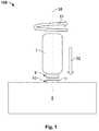
図1は、加工物5を被覆する方法の第1の実施形態を示す。加工物5は、電気構成要素、たとえばコンタクト素子または異なる導電素子とすることができる。加工物5はまた、機械的な機能を実現することができる。加工物は、特にマグネシウム、アルミニウム、もしくはチタン、またはこれらの元素の少なくとも1つを含む合金などの材料からなることができる。 FIG. 1 shows a first embodiment of a method for coating a
加工物5は、被覆材料10によって被覆されることが意図され、被覆材料10は、たとえば前のステップで提供されている。被覆材料10は、加工物5より高いまたは低い融点の材料を含むことができる。たとえば、被覆材料は、金、銀、またはパラジウムを含むことができる。 The
図示の例では、被覆材料10は、箔または薄板11として構成され、たとえばより大きい薄板から打ち抜いたものである。被覆機械100の摩擦体1が、加工物5上へ配置された後、押圧方向52に沿って被覆材料10上へ押圧される。この場合、摩擦体1は、回転方向51に沿って回転軸58の周りを回転し、その結果、摩擦体1の先端4および被覆材料10内、また加工物5の表面に、熱が発生する。これにより、被覆材料10と加工物5との間に融解が生じる。被覆材料10は、摩擦溶接または摩擦撹拌溶接によって加工物5に溶接され、加工物5上に被覆20を形成する。 In the example shown, the covering
被覆機械100は、単に概略的かつ部分的に示されているが、摩擦体1のための駆動部、摩擦体1のための押圧デバイス、被覆材料10のための位置決めデバイス、被覆材料10のための供給機構、およびさらなる要素を有することができる。 Although the
図2に、図1による方法によって形成された被覆20を見ることができる。被覆20は、加工物5の表面の一部領域のみに配置されている。被覆20のすぐ近傍には、同じ方法を使用して形成することができるさらなる被覆21が存在する。被覆21は、異なる特性を有することができ、異なる被覆材料10を含むことができる。たとえば、被覆20は、良好な接触のために配置することができ、はんだ付け可能な区域25を形成することができる。はんだ付け可能な区域25は、追加として、スズ、亜鉛、銀、金、または鉛などの材料を含むことができ、この箇所ではんだ接合部の形成が可能になり、または改善されることを確実にすることができる。被覆21は、耐腐食性があることを確実にすることができる。 FIG. 2 shows the
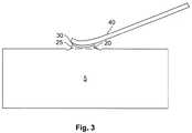
図3は、被覆20によってコンタクト素子40を加工物5にどのようにはんだ付けすることができるかを示す。この場合、はんだ30が接合部として働く。被覆20は、コンタクト素子40の簡単な蝋付けを可能にし、加工物5を化学物質で前処理する必要はない。 FIG. 3 shows how the
図4は、加工物5とコンタクト素子45との解放可能な接触を示す。コンタクト素子45は、接触方向55に沿って被覆20上へ動かされる。ここで、被覆20は、コンタクト素子45と加工物5との間に低い再現可能な境界抵抗が存在することを確実にすることができる。 FIG. 4 shows the releasable contact between the
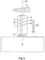
図5は、方法のさらなる構成を示す。ここに図示の例では、被覆材料10は、粉末12またはスラリー13として供給される。追加として、摩擦体1内に供給チャネル2が存在し、供給チャネル2は摩擦体1の先端4に通じている。被覆材料10は、供給チャネル2から出てくることができ、摩擦体1によって加工物5へ溶接することができる。供給チャネル2は、回転中に回転軸の周りを回転できるように、特に、摩擦体1内に非対称に配置することができる。このように、供給される被覆材料10は、押圧面を有する押圧領域内へ自動的に入り、その後加熱され得る。したがって供給チャネル2は特に、回転軸58と同心円状にすることはできない。 FIG. 5 shows a further configuration of the method. In the example shown here, the
図示の方法は特に、摩擦溶接または摩擦撹拌溶接で行われるものと同様に、器具、すなわち摩擦体1の回転によって被覆材料10が加熱され、加工物5に融解され、または加工物5とともに混合もしくは拡散されるステップを含む。 The method shown in particular is such that the
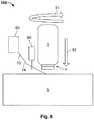
図6は、被覆材料10がワイヤ14の形状で供給される一実施形態を示す。追加として、被覆機械100は、ワイヤ14を所望の被覆箇所へ供給する供給デバイス60を備えることができる。 FIG. 6 shows one embodiment in which the
1 摩擦体
2 供給チャネル
4 先端
5 加工物
10 被覆材料
11 薄板
12 粉末
13 スラリー
14 ワイヤ
20 被覆
21 被覆
25 はんだ付け可能な区域
30 はんだ
40 コンタクト素子
45 コンタクト素子
51 回転方向
52 押圧方向
55 接触方向
58 回転軸
100 被覆機械DESCRIPTION OF
Claims (14)
Translated fromJapaneseApplications Claiming Priority (2)
| Application Number | Priority Date | Filing Date | Title |
|---|---|---|---|
| DE102018212156.7ADE102018212156A1 (en) | 2018-07-20 | 2018-07-20 | Method for coating a workpiece, workpiece, coating machine, and use of a friction welding device |
| DE102018212156.7 | 2018-07-20 |
Publications (2)
| Publication Number | Publication Date |
|---|---|
| JP2020011299Atrue JP2020011299A (en) | 2020-01-23 |
| JP7482611B2 JP7482611B2 (en) | 2024-05-14 |
Family
ID=67437904
Family Applications (1)
| Application Number | Title | Priority Date | Filing Date |
|---|---|---|---|
| JP2019131538AActiveJP7482611B2 (en) | 2018-07-20 | 2019-07-17 | Method for coating a workpiece, use of the workpiece, coating machine, and friction welding device - Patents.com |
Country Status (6)
| Country | Link |
|---|---|
| US (1) | US20200023459A1 (en) |
| EP (1) | EP3597350A1 (en) |
| JP (1) | JP7482611B2 (en) |
| KR (1) | KR102779849B1 (en) |
| CN (1) | CN110732769A (en) |
| DE (1) | DE102018212156A1 (en) |
Families Citing this family (1)
| Publication number | Priority date | Publication date | Assignee | Title |
|---|---|---|---|---|
| CN111331246A (en)* | 2020-04-17 | 2020-06-26 | 哈尔滨万洲焊接技术有限公司 | Method and device for friction stir welding of dissimilar metals |
Citations (10)
| Publication number | Priority date | Publication date | Assignee | Title |
|---|---|---|---|---|
| US6457629B1 (en)* | 1999-10-04 | 2002-10-01 | Solidica, Inc. | Object consolidation employing friction joining |
| JP2006045645A (en)* | 2004-08-06 | 2006-02-16 | Furukawa Alflex Corp | Device and method for bonding dissimilar metals, and metal component |
| JP2007100129A (en)* | 2005-09-30 | 2007-04-19 | Mitsui Eng & Shipbuild Co Ltd | Surface coating method and surface coating film |
| US20080041921A1 (en)* | 2005-09-26 | 2008-02-21 | Kevin Creehan | Friction stir fabrication |
| EP1952931A1 (en)* | 2007-02-05 | 2008-08-06 | Siemens Aktiengesellschaft | Mechtrode with powder feed and method for utilising such mechtrode |
| US20100092789A1 (en)* | 2008-10-10 | 2010-04-15 | The Boeing Company | System and method for integrally forming a stiffener with a fiber metal laminate |
| DE102009000892A1 (en)* | 2008-11-25 | 2010-06-17 | Slv Halle Gmbh | Method for layer application of film-shaped soldering materials by ultrasonic welding on same or different surfaces of component, comprises coupling the ultrasonics on component surface to its activation and wettability |
| WO2013113492A1 (en)* | 2012-01-31 | 2013-08-08 | Hochschule Für Angewandte Wissenschaften - Fachhochschule Kempten | Method and device for the friction-coating of a surface of a workpiece |
| US20170043428A1 (en)* | 2014-04-24 | 2017-02-16 | Korea Institute Of Industrial Technology | Method of manufacturing composite material |
| US20170222345A1 (en)* | 2014-08-13 | 2017-08-03 | Auto-Kabel Management Gmbh | Electrical connection element, process to manufacture an electrical connection element and use of an electrical connection element |
Family Cites Families (15)
| Publication number | Priority date | Publication date | Assignee | Title |
|---|---|---|---|---|
| WO1991010757A1 (en)* | 1990-01-16 | 1991-07-25 | Etienne Broult | Method and apparatus for depositing on a solid substrate a solid additive material consisting of particles of at least one metal, alloy or metalloid |
| JP3400994B2 (en)* | 2001-09-05 | 2003-04-28 | 川崎重工業株式会社 | Friction stir welding equipment |
| US6572007B1 (en)* | 2002-01-23 | 2003-06-03 | General Motors Corporation | Method for attaching metal members |
| DE102005029881A1 (en)* | 2005-06-27 | 2006-12-28 | Gkss-Forschungszentrum Geesthacht Gmbh | Friction stir welding apparatus includes pin to form plasticized zone, first friction surface segment having first friction surface for resting on the workpiece, and feed device for introducing filler material into the plasticized zone |
| US8875976B2 (en)* | 2005-09-26 | 2014-11-04 | Aeroprobe Corporation | System for continuous feeding of filler material for friction stir welding, processing and fabrication |
| US8397974B2 (en)* | 2005-09-26 | 2013-03-19 | Aeroprobe Corporation | Self-reacting friction stir welding tool with the ability to add filler material |
| US8632850B2 (en)* | 2005-09-26 | 2014-01-21 | Schultz-Creehan Holdings, Inc. | Friction fabrication tools |
| US7624910B2 (en)* | 2006-04-17 | 2009-12-01 | Lockheed Martin Corporation | Perforated composites for joining of metallic and composite materials |
| US7997472B2 (en)* | 2008-10-14 | 2011-08-16 | GM Global Technology Operations LLC | Friction stir welding using an adhesive, copper, tin and zinc interlayer |
| US8603571B2 (en)* | 2011-05-23 | 2013-12-10 | GM Global Technology Operations LLC | Consumable tool friction stir processing of metal surfaces |
| KR20150123197A (en)* | 2015-07-13 | 2015-11-03 | 한국생산기술연구원 | Method of manufacturing for composite materials |
| JP2018532044A (en)* | 2015-09-03 | 2018-11-01 | クエステック イノベーションズ リミテッド ライアビリティ カンパニー | Aluminum alloy |
| US20170304933A1 (en)* | 2016-04-20 | 2017-10-26 | Brigham Young University | Friction stir additive processing and methods thereof |
| WO2017220863A1 (en)* | 2016-06-23 | 2017-12-28 | Aalto University Foundation | A non-consumable tool and a process for solid-state production of a channel and a weld joint, and a structure of at least two components based on originally bulk components of similar, or dissimilar, materials |
| FR3059578B1 (en)* | 2016-12-07 | 2019-06-28 | Constellium Issoire | METHOD FOR MANUFACTURING A STRUCTURE ELEMENT |
- 2018
- 2018-07-20DEDE102018212156.7Apatent/DE102018212156A1/enactivePending
- 2019
- 2019-07-17CNCN201910644522.8Apatent/CN110732769A/enactivePending
- 2019-07-17JPJP2019131538Apatent/JP7482611B2/enactiveActive
- 2019-07-18KRKR1020190087144Apatent/KR102779849B1/enactiveActive
- 2019-07-18EPEP19186875.1Apatent/EP3597350A1/enactivePending
- 2019-07-19USUS16/516,852patent/US20200023459A1/enactivePending
Patent Citations (10)
| Publication number | Priority date | Publication date | Assignee | Title |
|---|---|---|---|---|
| US6457629B1 (en)* | 1999-10-04 | 2002-10-01 | Solidica, Inc. | Object consolidation employing friction joining |
| JP2006045645A (en)* | 2004-08-06 | 2006-02-16 | Furukawa Alflex Corp | Device and method for bonding dissimilar metals, and metal component |
| US20080041921A1 (en)* | 2005-09-26 | 2008-02-21 | Kevin Creehan | Friction stir fabrication |
| JP2007100129A (en)* | 2005-09-30 | 2007-04-19 | Mitsui Eng & Shipbuild Co Ltd | Surface coating method and surface coating film |
| EP1952931A1 (en)* | 2007-02-05 | 2008-08-06 | Siemens Aktiengesellschaft | Mechtrode with powder feed and method for utilising such mechtrode |
| US20100092789A1 (en)* | 2008-10-10 | 2010-04-15 | The Boeing Company | System and method for integrally forming a stiffener with a fiber metal laminate |
| DE102009000892A1 (en)* | 2008-11-25 | 2010-06-17 | Slv Halle Gmbh | Method for layer application of film-shaped soldering materials by ultrasonic welding on same or different surfaces of component, comprises coupling the ultrasonics on component surface to its activation and wettability |
| WO2013113492A1 (en)* | 2012-01-31 | 2013-08-08 | Hochschule Für Angewandte Wissenschaften - Fachhochschule Kempten | Method and device for the friction-coating of a surface of a workpiece |
| US20170043428A1 (en)* | 2014-04-24 | 2017-02-16 | Korea Institute Of Industrial Technology | Method of manufacturing composite material |
| US20170222345A1 (en)* | 2014-08-13 | 2017-08-03 | Auto-Kabel Management Gmbh | Electrical connection element, process to manufacture an electrical connection element and use of an electrical connection element |
Also Published As
| Publication number | Publication date |
|---|---|
| DE102018212156A1 (en) | 2020-01-23 |
| KR20200010111A (en) | 2020-01-30 |
| CN110732769A (en) | 2020-01-31 |
| JP7482611B2 (en) | 2024-05-14 |
| EP3597350A1 (en) | 2020-01-22 |
| US20200023459A1 (en) | 2020-01-23 |
| KR102779849B1 (en) | 2025-03-10 |
Similar Documents
| Publication | Publication Date | Title |
|---|---|---|
| US7021521B2 (en) | Bump connection and method and apparatus for forming said connection | |
| JP5529983B2 (en) | Soldering iron, method of manufacturing electronic equipment using the same, and manufacturing apparatus | |
| US7699208B2 (en) | Soldering tip, soldering iron, and soldering system | |
| JPS5824941B2 (en) | welding equipment | |
| JP2008004651A (en) | Bonding material using anisotropic fine particles | |
| TW201343310A (en) | Bonding method, bond structure, and manufacturing method for same | |
| CN104736288A (en) | Method and apparatus for connecting a conductor to a substrate | |
| JP2007288095A (en) | Semiconductor device and spot friction stir welding apparatus used for manufacturing the same | |
| CN107835724B (en) | Joining member and method for manufacturing joining member | |
| CN113808953B (en) | Batch welding of different components in power modules | |
| JP2014180690A (en) | Sheet-like high-temperature solder joint material, and die bonding method using the same | |
| JP7482611B2 (en) | Method for coating a workpiece, use of the workpiece, coating machine, and friction welding device - Patents.com | |
| CN105269161A (en) | Current schedule for optimized reaction metallurgical joining | |
| JP2023013803A (en) | Joining apparatus and joining method for friction stir welding and resistance welding | |
| JP2023013804A (en) | Joining apparatus and joining method for friction stir welding and resistance welding | |
| KR101733023B1 (en) | Curing agent, heat-curable resin composition containing said curing agent, joining method using said composition, and method for controlling curing temperature of heat-curable resin | |
| JP5406608B2 (en) | Resistance welding machine and resistance welding method | |
| TW201227852A (en) | Manufacturing method of a solder ball | |
| CN117300434B (en) | Packaging soldering lug and preparation method thereof | |
| JP6488896B2 (en) | Package sealing method and sealing paste | |
| JP2004119944A (en) | Semiconductor module and mounting substrate | |
| JP2011086717A (en) | Circuit device and method of manufacturing the same | |
| JP6552464B2 (en) | Joining structure of dissimilar metals, joining method thereof, and production method of electrical product | |
| JP3683247B2 (en) | Micro joint metal joining method and conductive tape | |
| JPWO2020050330A1 (en) | How to apply solder paste and mask |
Legal Events
| Date | Code | Title | Description |
|---|---|---|---|
| A621 | Written request for application examination | Free format text:JAPANESE INTERMEDIATE CODE: A621 Effective date:20220711 | |
| A977 | Report on retrieval | Free format text:JAPANESE INTERMEDIATE CODE: A971007 Effective date:20230428 | |
| A131 | Notification of reasons for refusal | Free format text:JAPANESE INTERMEDIATE CODE: A131 Effective date:20230509 | |
| A521 | Request for written amendment filed | Free format text:JAPANESE INTERMEDIATE CODE: A523 Effective date:20230807 | |
| A02 | Decision of refusal | Free format text:JAPANESE INTERMEDIATE CODE: A02 Effective date:20231114 | |
| A521 | Request for written amendment filed | Free format text:JAPANESE INTERMEDIATE CODE: A523 Effective date:20240104 | |
| A521 | Request for written amendment filed | Free format text:JAPANESE INTERMEDIATE CODE: A821 Effective date:20240104 | |
| A521 | Request for written amendment filed | Free format text:JAPANESE INTERMEDIATE CODE: A821 Effective date:20240104 | |
| A911 | Transfer to examiner for re-examination before appeal (zenchi) | Free format text:JAPANESE INTERMEDIATE CODE: A911 Effective date:20240307 | |
| TRDD | Decision of grant or rejection written | ||
| A01 | Written decision to grant a patent or to grant a registration (utility model) | Free format text:JAPANESE INTERMEDIATE CODE: A01 Effective date:20240402 | |
| A61 | First payment of annual fees (during grant procedure) | Free format text:JAPANESE INTERMEDIATE CODE: A61 Effective date:20240430 | |
| R150 | Certificate of patent or registration of utility model | Ref document number:7482611 Country of ref document:JP Free format text:JAPANESE INTERMEDIATE CODE: R150 |