JP2020006477A - Elastic ring mounting jig - Google Patents
Elastic ring mounting jigDownload PDFInfo
- Publication number
- JP2020006477A JP2020006477AJP2018129616AJP2018129616AJP2020006477AJP 2020006477 AJP2020006477 AJP 2020006477AJP 2018129616 AJP2018129616 AJP 2018129616AJP 2018129616 AJP2018129616 AJP 2018129616AJP 2020006477 AJP2020006477 AJP 2020006477A
- Authority
- JP
- Japan
- Prior art keywords
- elastic ring
- pusher
- mounting jig
- ring
- seal ring
- Prior art date
- Legal status (The legal status is an assumption and is not a legal conclusion. Google has not performed a legal analysis and makes no representation as to the accuracy of the status listed.)
- Granted
Links
Images


Classifications
- B—PERFORMING OPERATIONS; TRANSPORTING
- B25—HAND TOOLS; PORTABLE POWER-DRIVEN TOOLS; MANIPULATORS
- B25B—TOOLS OR BENCH DEVICES NOT OTHERWISE PROVIDED FOR, FOR FASTENING, CONNECTING, DISENGAGING OR HOLDING
- B25B27/00—Hand tools, specially adapted for fitting together or separating parts or objects whether or not involving some deformation, not otherwise provided for
- B25B27/02—Hand tools, specially adapted for fitting together or separating parts or objects whether or not involving some deformation, not otherwise provided for for connecting objects by press fit or detaching same
Landscapes
- Engineering & Computer Science (AREA)
- Mechanical Engineering (AREA)
- Hand Tools For Fitting Together And Separating, Or Other Hand Tools (AREA)
- Automatic Assembly (AREA)
Abstract
Description
Translated fromJapanese本発明は、対象物の環状溝に対して環状の弾性リングを装着するための弾性リング取付治具に関する。 The present invention relates to an elastic ring attaching jig for attaching an annular elastic ring to an annular groove of an object.
従来から、断面円形状に形成された対象物の環状溝に対してパッキン等の弾性リング体を装着するための取付治具が知られており、このような取付治具は、例えば、特許文献1に開示されるように、重ね合わせた2枚の板部材の両端部を固定具によって互いに連結することで構成される。 Conventionally, a mounting jig for mounting an elastic ring body such as a packing in an annular groove of an object formed in a circular cross section has been known, and such a mounting jig is disclosed in, for example, Patent Document 1. As disclosed in JP-A No. 1, the both ends of two superposed plate members are connected to each other by a fixture.
この取付治具を用いて円筒状に形成されたガイドの下端に対してリング状パッキンを装着する場合には、先ず該ガイドの上端にリング状パッキンを挿通させて配置し、その上方から取付治具を一方の板部材と他方の板部材との間となるように前記上端に対して押し付けていく。これにより、各板部材の下端部がリング状パッキンの上面へ当接し、一方の板部材と他方の板部材とがガイドを挟んで互いに離間しながら下方へと移動することで、前記リング状パッキンが下端側へと押圧されて移動する。 When mounting a ring-shaped packing on the lower end of a cylindrical guide using this mounting jig, first place the ring-shaped packing through the upper end of the guide and arrange it from above. The tool is pressed against the upper end so as to be between one plate member and the other plate member. As a result, the lower end of each plate member abuts on the upper surface of the ring-shaped packing, and one plate member and the other plate member move downward while being separated from each other with the guide interposed therebetween. Is pressed toward the lower end and moves.
そして、取付治具による押圧作用下にガイドの下端に設けられたパッキン装着溝までリング状パッキンが到達し、弾性によって径方向内側へと縮径することで該パッキン装着溝へと装着される。 Then, the ring-shaped packing reaches the packing mounting groove provided at the lower end of the guide under the pressing action of the mounting jig, and is reduced in diameter inward by elasticity to be mounted in the packing mounting groove.
しかしながら、上述した取付治具では、ガイドを挟んで分離した2枚の板部材によって環状のリング状パッキンを押圧する構成としているため、板部材によって環状の前記リング状パッキンを全周にわたって押圧することができず、該板部材の当接する一部のみを押圧することとなる。そのため、リング状パッキンがガイドに沿って移動することでねじれが生じ、それに伴って、前記リング状パッキンを移動させる際の移動速度が低下してしまうと共に、このねじれが生じた状態でパッキン装着溝へと装着されるとシール性が低下してしまうという問題がある。 However, in the mounting jig described above, since the annular ring-shaped packing is pressed by two plate members separated by sandwiching the guide, the ring-shaped packing is pressed by the plate member over the entire circumference. Cannot be performed, and only a part of the plate member in contact with the plate member is pressed. Therefore, when the ring-shaped packing moves along the guide, a twist is generated, and accordingly, the moving speed at the time of moving the ring-shaped packing is reduced, and the packing mounting groove is formed in a state where the twist is generated. There is a problem that the sealing performance is deteriorated when the device is mounted.
また、パッキン装着溝よりもリング状パッキンの挿入される上方に凹部や凸部があった場合、前記パッキン装着溝まで前記リング状パッキンを円滑に移動させることができず、作業性の低下を招くこととなる。 In addition, when there is a concave portion or a convex portion above the packing groove in which the ring-shaped packing is inserted, the ring-shaped packing cannot be smoothly moved to the packing-mounting groove, resulting in a decrease in workability. It will be.
本発明は、前記の課題を考慮してなされたものであり、弾性リングを装着する際のねじれを防止し、所望の位置に確実且つ効率的に装着すると共に、シール性の確保を図ることが可能な弾性リング取付治具を提供することを目的とする。 The present invention has been made in consideration of the above problems, and prevents torsion at the time of mounting an elastic ring, reliably and efficiently mounts the elastic ring at a desired position, and ensures sealing performance. It is an object to provide a possible elastic ring mounting jig.
前記の目的を達成するために、本発明の態様は、弾性リングの装着される環状溝を表面に有した対象物に沿って弾性リングを移動可能な弾性リング取付治具であって、
弾性リング取付治具は、弾性リングの取り付けられるリング取付部と、
弾性リングの移動方向において全周に当接し、環状溝に向かって弾性リングを押し出すプッシャと、
を有し、
プッシャは、移動方向と直交する方向において、対象物の表面側となる弾性リングの一部を押圧している。In order to achieve the above object, an aspect of the present invention is an elastic ring mounting jig capable of moving an elastic ring along an object having an annular groove on the surface to which the elastic ring is attached,
The elastic ring mounting jig has a ring mounting portion to which the elastic ring is mounted,
A pusher that comes into contact with the entire circumference in the moving direction of the elastic ring and pushes the elastic ring toward the annular groove;
Has,
The pusher presses a part of the elastic ring on the surface side of the object in a direction orthogonal to the moving direction.
本発明によれば、弾性リングを対象物の環状溝へと装着するための弾性リング取付治具において、弾性リングの取り付けられるリング取付部と、弾性リングの移動方向において全周に当接し、環状溝に向かって弾性リングを押し出すプッシャとを備え、このプッシャが、弾性リングの移動方向と直交する方向において、弾性リングにおける対象物の表面側となる一部を押圧する構成としている。 According to the present invention, in an elastic ring attaching jig for attaching an elastic ring to an annular groove of an object, a ring attaching portion to which the elastic ring is attached, and an abutment with the entire circumference in the moving direction of the elastic ring, A pusher that pushes the elastic ring toward the groove; and the pusher presses a part of the elastic ring on the surface side of the object in a direction orthogonal to the moving direction of the elastic ring.
従って、弾性リングの装着された弾性リング取付治具を対象物の表面に沿って移動させ、リング取付部に取り付けられた弾性リングをプッシャによって押し出すことにより環状溝へと装着できると共に、弾性リングにおいて対象物の表面側となる一部をプッシャによって押圧することで、弾性リング内周と弾性リング取付治具との間に発生する摩擦とねじれモーメントとを相殺してねじれを発生させることなく環状溝へと移動させ装着することができる。 Therefore, the elastic ring mounting jig on which the elastic ring is mounted is moved along the surface of the object, and the elastic ring mounted on the ring mounting portion can be mounted on the annular groove by being pushed out by the pusher. By pressing a part of the object on the surface side with a pusher, the friction generated between the inner periphery of the elastic ring and the elastic ring mounting jig and the torsional moment are offset, and the annular groove is generated without causing torsion. And can be mounted.
その結果、プッシャによって弾性リングを対象物の環状溝に対して確実且つ効率的に装着することが可能となり、しかも、弾性リングが移動する際のねじれが好適に防止されることで、弾性リングによるシール性を確保することができ効率的に作業することができる。また、対象物の表面に沿って弾性リングを移動させる距離が長い場合でも、弾性リングがねじれることなく環状溝に取り付けることが可能となる。 As a result, the elastic ring can be securely and efficiently attached to the annular groove of the object by the pusher, and the elastic ring can be suitably prevented from being twisted when moving. Sealing properties can be ensured and work can be performed efficiently. Further, even when the distance for moving the elastic ring along the surface of the object is long, the elastic ring can be attached to the annular groove without being twisted.
本発明によれば、以下の効果が得られる。 According to the present invention, the following effects can be obtained.
すなわち、弾性リングの装着された弾性リング取付治具を対象物の表面に沿って移動させ、リング取付部に取り付けられた弾性リングをプッシャによって押し出すことにより環状溝へと装着すると共に、弾性リングにおいて対象物の表面側となる一部をプッシャによって押圧することで、ねじれを発生させることなく環状溝へと移動させ装着することができる。その結果、プッシャによって弾性リングを対象物の環状溝に対して確実且つ効率的に装着することが可能となり、しかも、弾性リングが移動する際のねじれが好適に防止されることで、弾性リングによるシール性を確保しつつ効率的に作業を行うことができる。 That is, the elastic ring mounting jig with the elastic ring attached is moved along the surface of the target object, and the elastic ring attached to the ring attaching portion is pushed out by a pusher to be attached to the annular groove, and the elastic ring is attached to the elastic ring. By pressing a part of the front surface side of the target object with the pusher, the target object can be moved to the annular groove and mounted without twisting. As a result, the elastic ring can be securely and efficiently attached to the annular groove of the object by the pusher, and the elastic ring can be suitably prevented from being twisted when moving. Work can be performed efficiently while ensuring sealing performance.
本発明に係る弾性リング取付治具について好適な実施の形態を挙げ、添付の図面を参照しながら以下詳細に説明する。図1において、参照符号10は、本発明の実施の形態に係る弾性リング取付治具10(以下、取付治具10という)を示す。 A preferred embodiment of an elastic ring mounting jig according to the present invention will be described below in detail with reference to the accompanying drawings. In FIG. 1,
この取付治具10は、図1〜図3に示されるように、円環状に形成されたプッシャ12と、該プッシャ12の基端側(矢印A方向)に連結された円環状のホルダ14と、前記プッシャ12の内周側に設けられ該プッシャ12をスライド自在に保持するボディ16とを含む。すなわち、取付治具10を構成するプッシャ12、ホルダ14及びボディ16は全て環状に形成される。 As shown in FIGS. 1 to 3, the
なお、以下の説明においては、取付治具10におけるホルダ14側を基端側(矢印A方向)、後述するプッシャ12の押圧部22側を先端側(矢印B方向)として説明する。 In the following description, the
プッシャ12は、例えば、軸方向(矢印A、B方向)に沿って延在した本体部18と、該本体部18の先端に形成され弾性リングであるシールリング20を軸方向(矢印B方向)に押圧可能な押圧部22とを有し、前記本体部18は略一定径で形成され、その基端には周方向に沿って互いに離間するように複数のねじ孔24が形成されている。 The
押圧部22は、本体部18に対して径方向内側へと延在し、該本体部18の内周面より径方向内側へと突出して形成される。この押圧部22は、本体部18から離間する方向(矢印B方向)に向かって徐々に傾斜した傾斜部26と、該傾斜部26の先端に形成された平坦部28とを有している。 The
傾斜部26は、プッシャ12の中心に向かって先端側(矢印B方向)へと傾斜するように形成され、その径方向内側が最も先端側へと突出し、その部位に平坦部28が設けられている。すなわち、傾斜部26は、プッシャ12の軸方向(矢印A、B方向)に対して所定角度だけ傾斜して形成されている。 The
平坦部28は、プッシャ12の軸方向と略直交した環状に形成され、押圧部22において最も内周側に形成されている。 The
また、押圧部22の基端側(矢印A方向)には、本体部18の内周面に対して直交するように径方向内側へ突出した段部30を有し、この段部30は、本体部18の内周面から平坦部28の内周側まで延在している。換言すれば、段部30は、平坦部28と略平行に形成されている。 Further, on the base end side (in the direction of arrow A) of the
ホルダ14は、例えば、円環状の平板からなり、プッシャ12の軸方向(矢印A、B方向)と略直交するように配置され、該プッシャ12における本体部18の基端に対して当接すると共に、その外周側が前記本体部18に対して径方向外側に突出するように設けられる。また、ホルダ14は、プッシャ12に対して径方向内側に所定長さだけ突出し、先端側(矢印B方向)に向かって突出した突部32が設けられ、この突部32の外周面が本体部18の内周面に当接するように設けられる。このホルダ14は、取付治具10によってシールリング20を装着する際、図示しない作業者が把持したり押圧したりするために用いられる。 The
突部32には、その先端側に開口し軸方向(矢印A方向)に窪んだ第1凹部34が形成され、この第1凹部34にはホルダ14の周方向に沿って複数設けられ、後述するスプリング(弾発部材)44の基端が介装される。 The
そして、ホルダ14には、その周方向に沿って互いに離間するように複数のボルト孔36が開口して貫通し、前記ホルダ14の先端面にプッシャ12における本体部18の基端が当接した状態で、前記ボルト孔36に締結ボルト38が挿通され、前記プッシャ12のねじ孔24へと螺合される。これにより、ホルダ14とプッシャ12とが一体的に連結される。 A plurality of bolt holes 36 are opened and penetrated in the
ボディ16は、プッシャ12に対して小径な円筒状に形成され、その基端がホルダ14の突部32に臨むように設けられると共に、その外周面がプッシャ12における本体部18に摺接し、内周面が略同一径で形成される。 The
また、ボディ16の基端には、内周面に対して径方向内側へと突出した環状の位置決め部40と、ホルダ14の第1凹部34に臨む複数の第2凹部42とを備え、前記位置決め部40は、例えば、ボディ16の軸線と直交した面を有している。そして、位置決め部40の内周径は、ホルダ14の内周径と略同一に形成される。 In addition, the base end of the
第2凹部42は、ボディ16の基端に開口して先端側(矢印B方向)へと窪んで形成され、第1凹部34に対応した同数設けられると共に、前記第1凹部34と前記第2凹部42との間にそれぞれスプリング44が介装される。スプリング44は、例えば、コイルスプリングからなり、ボディ16をホルダ14から離間させる方向(矢印B方向)へと付勢している。 The second
一方、ボディ16の先端側には、プッシャ12の段部30に係合可能な係合端部46を有し、前記係合端部46の先端は、ボディ16の軸方向に対して直交するように形成され、この係合端部46の内周側には、該係合端部46に対してさらに先端側(矢印B方向)へと突出した取付部(リング取付部)48を備える。 On the other hand, the distal end of the
そして、ボディ16は、プッシャ12の内周側において、その先端側となる係合端部46が段部30に当接する位置(図2及び図3参照)から基端がホルダ14の突部32へと当接する位置(図5C及び図5D参照)までの所定距離だけ軸方向(矢印A、B方向)に移動自在に設けられると共に、スプリング44の弾発作用下にホルダ14から離間する方向に付勢され、係合端部46が前記段部30へと当接した状態で保持される。 The
取付部48は、径方向において一定厚さで軸方向(矢印B方向)に沿って延在し、その内周面が同一径となるように形成されると共に、プッシャ12の押圧部22に対して内周側となるように配置される。また、取付部48は、図2及び図3に示されるように、ボディ16の係合端部46が段部30へと係合された際、押圧部22の先端(平坦部28)から所定長さだけ突出するように形成される。 The
そして、取付治具10を用いてワークへシールリング20を装着する際、プッシャ12より突出した取付部48の先端外周側に前記シールリング20が装着され保持される。 When the
本発明の実施の形態に係る取付治具10は、基本的には以上のように構成されるものであり、次に、前記取付治具10を用いてシールリング20を対象物となるステータホルダ60へと装着する場合について説明する。 The mounting
先ず、対象物であるステータホルダ60について図4〜図5Dを参照しながら簡単に説明する。 First, the
このステータホルダ60は、内部にステータコア(図示せず)を収納可能な円筒状に形成され、軸方向(矢印A、B方向)に沿って所定長さを有し、その先端には、該ステータホルダ60を他部材へ取り付けるためのフランジ62が設けられている。 The
また、ステータホルダ60の外周面(表面)は、フランジ62を有した先端側(矢印B方向)に形成される大径部64と、基端側(矢印A方向)に形成され該大径部64に対して若干だけ小径な小径部66とを有し、前記大径部64は、前記フランジ62の近傍となる位置にシールリング20の装着される環状のシール溝(環状溝)68が形成されると共に、このシール溝68に対して隣接するように基端側にも別の環状溝70が形成されている。さらに、小径部66にも、径方向内側に窪んだ複数の環状凹部72が形成されている。 The outer peripheral surface (surface) of the
すなわち、ステータホルダ60の外周面は、シールリング20を装着するシール溝68以外にも複数の環状溝70や環状凹部72が形成された断面凹凸状に形成されている。 That is, the outer peripheral surface of the
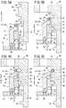
次に、上述したステータホルダ60のシール溝68に対して取付治具10を用いてシールリング20を装着する場合について、図4、図5A〜図5Dを参照しながら説明する。なお、取付治具10は、図4に示されるように、ホルダ14を下方としボディ16の取付部48が上方となるように用いる。 Next, a case where the
先ず、図4及び図5Aに示されるように、取付治具10における取付部48の先端外周面にシールリング20を装着する。この取付部48の外周径は、シールリング20の直径(内周径)よりも若干だけ大きく設定されるため、図示しない作業者が前記シールリング20を拡径させるように弾性変形させた状態で取付部48の外周側へと装着する。これにより、シールリング20の内周面が、全周にわたって取付部48の外周面へと接触し、且つ、プッシャ12の平坦部28が、前記シールリング20の先端面に対して全周にわたって接触した状態で保持される。 First, as shown in FIGS. 4 and 5A, the
詳細には、平坦部28は、シールリング20の先端面において、ステータホルダ60側となる径方向内側の一部のみに接触している。換言すれば、シールリング20の先端面は、径方向において径方向外側ではプッシャ12と非接触となるように配置されている。 Specifically, the
次に、図4に示されるように、シールリング20の装着されるステータホルダ60を上方とし、その先端側から取付治具10を前記ステータホルダ60の外周側へと挿通させていく(図5A参照)。この際、取付治具10は、その内周径がステータホルダ60の小径部66よりも大きく形成されているため、ステータホルダ60の外周面に沿って先端側(大径部64側)へと移動させることが可能となる。 Next, as shown in FIG. 4, the
そして、図5Bに示されるように、ボディ16の位置決め部40が、ステータホルダ60の大径部64と小径部66との境界部に当接することで係止され、さらなる先端側への移動が規制された位置決め状態となる。この際、ボディ16における取付部48の先端が、シール溝68の基端面と略同一面となるように配置される。 Then, as shown in FIG. 5B, the positioning
すなわち、ボディ16は、その位置決め部40から取付部48の先端までの長さが、ステータホルダ60における大径部64と小径部66との境界部からシール溝68の基端面までの距離と略同一となるように形成されている。 That is, the length of the
この取付治具10がステータホルダ60の外周側において軸方向(矢印B方向)に位置決めされた状態で、図5Cに示されるように、図示しない作業者がホルダ14を先端側(矢印B方向)に向かって押圧することで、該ホルダ14と共にプッシャ12がスプリング44の弾発力に抗して先端側(矢印B方向)へと所定距離だけ移動する。 In a state where the mounting
この際、ボディ16は、位置決め部40がステータホルダ60の大径部64に係合されることで先端側への移動が規制されているため移動することがない。このプッシャ12がボディ16に沿って先端側へと移動することで、その押圧部22によってシールリング20が軸方向に押圧され、取付部48に沿って先端側(矢印B方向)へと移動する。また、シールリング20は、重力によって下方となるプッシャ12の平坦部28へと密着した状態で上方へと押圧され移動する。 At this time, the
そして、図5Cに示されるように、シールリング20が押圧部22の押圧作用下に取付部48の先端まで移動し、突部32がボディ16に突き当たることによりストッパとして作用することで、該取付部48の先端と平坦部28とが略同一面となり、前記シールリング20が自らの弾性によって径方向内側へと縮径し、図5Dに示されるように、取付部48の先端に対して径方向内側に配置されたステータホルダ60のシール溝68へと収納され装着される。これにより、取付治具10を用いたステータホルダ60のシール溝68へのシールリング20の装着作業が完了する。 Then, as shown in FIG. 5C, the
以上のように、本実施の形態では、ステータホルダ60のような円筒状の対象物のシール溝68に対してシールリング20を装着可能な取付治具10において、プッシャ12の先端に前記シールリング20が全周にわたって当接するように設けられ、該プッシャ12の内周側に設けられたボディ16に対して前記プッシャ12が軸方向に移動自在に設けられると共に、前記ボディ16の先端に形成された取付部48の外周側にシールリング20が装着される構成としている。 As described above, in the present embodiment, in the mounting
従って、ステータホルダ60の外周側にシールリング20の装着された取付治具10を挿通させ、その取付部48が前記ステータホルダ60のシール溝68に臨む位置でボディ16を係止させた後、プッシャ12を該ボディ16に対して先端側へと相対移動させることで、プッシャ12でシールリング20を軸方向へと押圧して取付部48に沿って移動させることができる。 Therefore, after the mounting
また、シールリング20は、該シールリング20の移動方向(矢印A、B方向)と直交する方向(シールリング20の径方向)において、ステータホルダ60側となる内周側の一部がプッシャ12の平坦部28によって軸方向(矢印B方向)へと押圧される。そのため、シールリング20の外周側が軸方向へ押された場合に生じるねじれを、上記のように内周側となる部位を押圧することで好適に防止しながら移動させることが可能となる。 In the
その結果、プッシャ12によってシールリング20におけるステータホルダ60側(内周側)となる部位を軸方向へと押圧し、前記シールリング20を先端側へと移動させることで、ねじれの発生を好適に防止しつつ、対象物であるステータホルダ60のシール溝68へとシールリング20を確実且つ効率的に装着することが可能となる。 As a result, the portion of the
また、シールリング20のねじれを確実に防止しながらシール溝68へと装着することで、前記シール溝68に装着されたシールリング20によるシール性を確保することができると共に、その装着作業を効率的に行うことが可能となる。特に、シールリング20及びステータホルダ60が大径である場合により効果的である。さらに、シールリング20を移動させる距離が長い場合でも、軽量且つシンプルに構成することができる。 Further, by mounting the
さらにまた、取付治具10をステータホルダ60の外周面(大径部64、小径部66)に沿うように配置し、プッシャ12をシールリング20の移動方向に沿ってスライド自在に支持するボディ16を備えることで、前記ステータホルダ60の外周側において、前記シールリング20をシール溝68に臨む位置まで容易且つ確実に移動させることができる。 Furthermore, a
その結果、ステータホルダ60の外周面がシール溝68以外の環状溝70や環状凹部72を有した凹凸状である場合でも、シールリング20を所望のシール溝68へと確実に移動させて装着することが可能となる。 As a result, even when the outer peripheral surface of the
またさらに、ボディ16は、その外周側にプッシャ12が設けられ、その先端に形成された取付部48の外周側にシールリング20が装着される構成としている。これにより、ステータホルダ60のシール溝68に対して取付部48の先端を位置決めすることで、該取付部48に装着されたシールリング20を好適にシール溝68に対して位置決めできると共に、プッシャ12の内周側にボディ16を設けることで、該プッシャ12が軸方向に沿って移動する際に、該プッシャ12が前記ステータホルダ60の大径部64、小径部66に対して摺動することがないため、該大径部64を含むステータホルダ60の外周面の摩耗が好適に防止される。 Further, the
また、ボディ16は、その基端側において径方向内側へと突出してステータホルダ60の大径部64に係止される位置決め部40を有しているため、ステータホルダ60に対してボディ16を軸方向に確実に係止させることで、取付部48の先端をシール溝68に臨む位置へと高精度に位置決めすることが可能となる。 In addition, since the
さらに、ボディ16の取付部48を、シールリング20の移動方向においてシール溝68の基端面に臨む位置に位置決めすることで、ステータホルダ60の外周面に設けられ、且つ、シール溝68に対して挿入方向となる環状溝70や環状凹部72に誤って前記シールリング20が装着されてしまうことが回避され、所望のシール溝68に対して確実且つ高精度にシールリング20を装着することができる。 Further, by positioning the mounting
さらにまた、プッシャ12とボディ16とを、シールリング20の押し出し方向と反対方向(矢印A方向)に付勢するスプリング44を介して互いに連結することにより、図5Dに示されるように、前記シールリング20の装着後にスプリング44の弾発力を利用してプッシャ12をボディ16に対して相対移動させ所定位置へと復帰させることができる(図5A参照)。 Further, the
そのため、取付治具10を用いて複数の対象物(ステータホルダ60)へとシールリング20を連続的に装着する際、プッシャ12とボディ16とを作業者が手作業で初期位置へと復帰させる必要がなく、その作業効率を向上させることができる。 Therefore, when the
またさらに、上述した実施の形態では、取付治具10を用いてステータホルダ60のシール溝68へシールリング20を装着する場合について説明したがこれに限定されるものではなく、筒状の対象物に形成された環状溝70に対してシールリング20等の弾性リングを装着するものであればよい。 Further, in the above-described embodiment, the case where the
また、本発明に係る弾性リング取付治具10は、作業者が手動で取り扱うことを想定してスプリング44によってプッシャ12が初期位置へと戻る構成を採用しているが、例えば、自動化によってシールリング20の取り付けを行う場合にも本構成は有効であり、さらには、前記スプリング44の代わりとなる他の動力源に置き換えることも可能である。 Further, the elastic
なお、本発明に係る弾性リング取付治具10は、上述の実施の形態に限らず、本発明の要旨を逸脱することなく、種々の構成を採り得ることはもちろんである。 In addition, the elastic
10…弾性リング取付治具 12…プッシャ
14…ホルダ 16…ボディ
20…シールリング 22…押圧部
40…位置決め部 44…スプリング
48…取付部 60…ステータホルダ
68…シール溝DESCRIPTION OF
Claims (6)
Translated fromJapanese前記弾性リング取付治具は、前記弾性リングの取り付けられるリング取付部と、
前記弾性リングの移動方向において全周に当接し、前記環状溝に向かって該弾性リングを押し出すプッシャと、
を有し、
前記プッシャは、前記移動方向と直交する方向において、前記対象物の表面側となる前記弾性リングの一部を押圧している、弾性リング取付治具。An elastic ring mounting jig that can move the elastic ring along an object having an annular groove on the surface to which the elastic ring is attached,
The elastic ring mounting jig, a ring mounting portion to which the elastic ring is mounted,
A pusher that abuts the entire circumference in the moving direction of the elastic ring and pushes the elastic ring toward the annular groove;
Has,
An elastic ring mounting jig, wherein the pusher presses a part of the elastic ring on the surface side of the object in a direction orthogonal to the moving direction.
前記弾性リング取付治具は、前記対象物の表面に沿うように配置され、前記プッシャを前記弾性リングの移動方向に沿ってスライド自在に支持するボディを有する、弾性リング取付治具。The elastic ring mounting jig according to claim 1,
The elastic ring mounting jig, wherein the elastic ring mounting jig has a body arranged along the surface of the object and slidably supporting the pusher along a moving direction of the elastic ring.
前記ボディは、前記弾性リングの移動方向に沿った面に前記プッシャ及び前記リング取付部を備える、弾性リング取付治具。The elastic ring mounting jig according to claim 2,
The elastic ring mounting jig, wherein the body includes the pusher and the ring mounting portion on a surface along a moving direction of the elastic ring.
前記ボディは、前記対象物に対して前記弾性リングの移動方向に位置決め可能な位置決め部を有する、弾性リング取付治具。The elastic ring mounting jig according to claim 2 or 3,
The elastic ring mounting jig, wherein the body has a positioning portion that can be positioned with respect to the object in a moving direction of the elastic ring.
前記ボディの先端は、前記弾性リングの移動方向において前記環状溝の近傍に位置決めされる、弾性リング取付治具。The elastic ring mounting jig according to any one of claims 2 to 4,
An elastic ring mounting jig, wherein a tip of the body is positioned near the annular groove in a moving direction of the elastic ring.
前記プッシャと前記ボディとが、前記弾性リングの押し出し方向と反対方向に付勢する弾発部材を介して連結される、弾性リング取付治具。The elastic ring mounting jig according to any one of claims 2 to 5,
An elastic ring mounting jig, wherein the pusher and the body are connected via a resilient member that urges the elastic ring in a direction opposite to a pushing direction of the elastic ring.
Priority Applications (2)
| Application Number | Priority Date | Filing Date | Title |
|---|---|---|---|
| JP2018129616AJP7154848B2 (en) | 2018-07-09 | 2018-07-09 | Elastic ring mounting jig |
| CN201910615554.5ACN110695913A (en) | 2018-07-09 | 2019-07-09 | Elastic ring installation jig |
Applications Claiming Priority (1)
| Application Number | Priority Date | Filing Date | Title |
|---|---|---|---|
| JP2018129616AJP7154848B2 (en) | 2018-07-09 | 2018-07-09 | Elastic ring mounting jig |
Publications (2)
| Publication Number | Publication Date |
|---|---|
| JP2020006477Atrue JP2020006477A (en) | 2020-01-16 |
| JP7154848B2 JP7154848B2 (en) | 2022-10-18 |
Family
ID=69150101
Family Applications (1)
| Application Number | Title | Priority Date | Filing Date |
|---|---|---|---|
| JP2018129616AActiveJP7154848B2 (en) | 2018-07-09 | 2018-07-09 | Elastic ring mounting jig |
Country Status (2)
| Country | Link |
|---|---|
| JP (1) | JP7154848B2 (en) |
| CN (1) | CN110695913A (en) |
Cited By (1)
| Publication number | Priority date | Publication date | Assignee | Title |
|---|---|---|---|---|
| CN113510653A (en)* | 2021-08-06 | 2021-10-19 | 中铁十八局集团有限公司 | Device for assisting shield machine hob sealing ring assembly |
Families Citing this family (1)
| Publication number | Priority date | Publication date | Assignee | Title |
|---|---|---|---|---|
| CN112677098A (en)* | 2020-12-28 | 2021-04-20 | 宜昌南玻光电玻璃有限公司 | Rubber ring replacing device and rubber ring replacing method for conveying roller way |
Citations (4)
| Publication number | Priority date | Publication date | Assignee | Title |
|---|---|---|---|---|
| JPS627336U (en)* | 1985-06-25 | 1987-01-17 | ||
| JPS63179029U (en)* | 1987-05-13 | 1988-11-18 | ||
| US20040194277A1 (en)* | 2003-03-14 | 2004-10-07 | Michael Hunter | Single stroke O-ring insertion device |
| JP2010019293A (en)* | 2008-07-08 | 2010-01-28 | Ntn Corp | Annular elastomer mounting device |
Family Cites Families (7)
| Publication number | Priority date | Publication date | Assignee | Title |
|---|---|---|---|---|
| US4865080A (en)* | 1983-11-07 | 1989-09-12 | Lynn Lundquist | Elastomer die plug |
| JP2518280B2 (en)* | 1987-06-05 | 1996-07-24 | トヨタ自動車株式会社 | Assembly device for piston ring |
| US4821398A (en)* | 1988-03-03 | 1989-04-18 | Cordis Corporation | Method of attaching a sterile sleeve to a connector |
| JPH11347963A (en)* | 1998-06-05 | 1999-12-21 | Unisia Jecs Corp | Elastic ring mounting device |
| US20140215798A1 (en)* | 2013-02-05 | 2014-08-07 | Ellcon National, Inc. | System and method for installing a seal on a work piece |
| CN203679700U (en)* | 2014-01-17 | 2014-07-02 | 周俊雄 | Automatic feeding device of sealing ring |
| CN204545877U (en)* | 2015-05-01 | 2015-08-12 | 魏仕槚 | A kind of O type coil installing device |
- 2018
- 2018-07-09JPJP2018129616Apatent/JP7154848B2/enactiveActive
- 2019
- 2019-07-09CNCN201910615554.5Apatent/CN110695913A/enactivePending
Patent Citations (4)
| Publication number | Priority date | Publication date | Assignee | Title |
|---|---|---|---|---|
| JPS627336U (en)* | 1985-06-25 | 1987-01-17 | ||
| JPS63179029U (en)* | 1987-05-13 | 1988-11-18 | ||
| US20040194277A1 (en)* | 2003-03-14 | 2004-10-07 | Michael Hunter | Single stroke O-ring insertion device |
| JP2010019293A (en)* | 2008-07-08 | 2010-01-28 | Ntn Corp | Annular elastomer mounting device |
Cited By (1)
| Publication number | Priority date | Publication date | Assignee | Title |
|---|---|---|---|---|
| CN113510653A (en)* | 2021-08-06 | 2021-10-19 | 中铁十八局集团有限公司 | Device for assisting shield machine hob sealing ring assembly |
Also Published As
| Publication number | Publication date |
|---|---|
| CN110695913A (en) | 2020-01-17 |
| JP7154848B2 (en) | 2022-10-18 |
Similar Documents
| Publication | Publication Date | Title |
|---|---|---|
| JP6103349B2 (en) | Fluid pressure cylinder | |
| RU2010101643A (en) | CARTRIDGE FOR A MANUAL ELECTRIC MACHINE, FIRST FOR A CRACKING HAMMER AND / OR PUNCHER | |
| KR20140071432A (en) | Vibration-proof clamp | |
| TWI535510B (en) | Elastic chuck | |
| JP2020006477A (en) | Elastic ring mounting jig | |
| JP2013151953A (en) | Ring-shaped workpiece assembling method and assembling tool | |
| US20150014395A1 (en) | Welding fixture | |
| JP5917171B2 (en) | Fiber optic connector | |
| US9772001B2 (en) | Over-loading protection pressing device | |
| JP6046137B2 (en) | clip | |
| KR102342908B1 (en) | Jig for piston packing mounting | |
| WO2020009244A1 (en) | Machining tool | |
| US9393654B2 (en) | Instant clamping mechanism | |
| US20170307021A1 (en) | High-speed snap ring and snap ring retention method | |
| CN112536753A (en) | Multi-size wrench and conversion device thereof | |
| JP7537467B2 (en) | Ring mounting tool and ring mounting method | |
| JP2021028524A (en) | Fixture | |
| JP6237946B1 (en) | Retaining ring holder | |
| TWI736162B (en) | Screw removal tool | |
| JP2014221502A (en) | Assembly method by circlip, assembly object, and guide jig for attaching circlip | |
| JP2008221384A (en) | Tool holder | |
| JP6518762B2 (en) | Fluid pressure clamp device | |
| JP6389363B2 (en) | Parts mounting structure | |
| JP2010540856A (en) | Fixing device for sheath terminal end of Bowden cable | |
| JP2021109287A (en) | C-type retaining ring mounting jig and mounting method of c-type retaining ring using the same |
Legal Events
| Date | Code | Title | Description |
|---|---|---|---|
| A621 | Written request for application examination | Free format text:JAPANESE INTERMEDIATE CODE: A621 Effective date:20201130 | |
| A977 | Report on retrieval | Free format text:JAPANESE INTERMEDIATE CODE: A971007 Effective date:20210721 | |
| A131 | Notification of reasons for refusal | Free format text:JAPANESE INTERMEDIATE CODE: A131 Effective date:20210831 | |
| A521 | Request for written amendment filed | Free format text:JAPANESE INTERMEDIATE CODE: A523 Effective date:20211101 | |
| A131 | Notification of reasons for refusal | Free format text:JAPANESE INTERMEDIATE CODE: A131 Effective date:20220329 | |
| A521 | Request for written amendment filed | Free format text:JAPANESE INTERMEDIATE CODE: A523 Effective date:20220524 | |
| TRDD | Decision of grant or rejection written | ||
| A01 | Written decision to grant a patent or to grant a registration (utility model) | Free format text:JAPANESE INTERMEDIATE CODE: A01 Effective date:20221004 | |
| A61 | First payment of annual fees (during grant procedure) | Free format text:JAPANESE INTERMEDIATE CODE: A61 Effective date:20221005 | |
| R150 | Certificate of patent or registration of utility model | Ref document number:7154848 Country of ref document:JP Free format text:JAPANESE INTERMEDIATE CODE: R150 |