JP2020001442A - Work vehicle - Google Patents
Work vehicleDownload PDFInfo
- Publication number
- JP2020001442A JP2020001442AJP2018119980AJP2018119980AJP2020001442AJP 2020001442 AJP2020001442 AJP 2020001442AJP 2018119980 AJP2018119980 AJP 2018119980AJP 2018119980 AJP2018119980 AJP 2018119980AJP 2020001442 AJP2020001442 AJP 2020001442A
- Authority
- JP
- Japan
- Prior art keywords
- vehicle body
- link
- operation means
- vehicle
- turning
- Prior art date
- Legal status (The legal status is an assumption and is not a legal conclusion. Google has not performed a legal analysis and makes no representation as to the accuracy of the status listed.)
- Granted
Links
Images


Landscapes
- Vehicle Body Suspensions (AREA)
Abstract
Translated fromJapaneseDescription
Translated fromJapanese本発明は、凹凸の多い路面を走行するのに適した作業車に関する。 The present invention relates to a work vehicle suitable for traveling on a road surface having a lot of unevenness.
従来では、4つの走行車輪を夫々、横軸周りで揺動可能な2つの関節を持ち屈伸操作可能に構成されたリンク機構を介して車両本体に支持し、電動モータの駆動力によりリンク機構が屈伸駆動可能に構成され、走行車輪は、左右方向の向きが固定される状態で支持されたものがあった(例えば、特許文献1参照)。 Conventionally, four traveling wheels are each supported on a vehicle body via a link mechanism having two joints capable of swinging about a horizontal axis and capable of bending and extending, and the link mechanism is driven by an electric motor. There has been one that is configured to be able to bend and extend and that the traveling wheel is supported in a state where the direction in the left-right direction is fixed (for example, see Patent Document 1).
上記従来構成は、リンク機構を屈伸させながら複数の走行装置を各別に高さ変更させることにより、凹凸の多い路面であっても車両本体の姿勢を安定させた状態で走行することが可能であるが、リンク機構は横軸芯周りで揺動して屈伸する構成であり、走行車輪は高さが変化しても向きは一定である。 In the above-described conventional configuration, by changing the height of each of the plurality of traveling devices while bending and extending the link mechanism, it is possible to travel in a state where the posture of the vehicle body is stabilized even on a road surface having a lot of unevenness. However, the link mechanism swings around the horizontal axis and bends and stretches, and the direction of the traveling wheel is constant even when the height changes.
その結果、車両本体を左右いずれかの方向に旋回走行させる場合には、左右の走行車輪に速度差を付けて旋回させるか、あるいは、別途備えられたロボットアーム(多関節マニピュレータ)を用いて車体の向きを変更させる必要がある。このような構成では、走行車輪が横滑りしながら走行することになり、旋回操作が滑らかに行えない不利があるとともに、横方向に沿って無理な力が加わることがあり、耐久性が低下するおそれがある。 As a result, when turning the vehicle body in one of the right and left directions, the vehicle body is turned with a speed difference between the left and right traveling wheels, or the vehicle body is provided by using a separately provided robot arm (articulated manipulator). Needs to be changed. In such a configuration, the traveling wheels run while skidding, which is disadvantageous in that the turning operation cannot be performed smoothly, and an excessive force may be applied along the lateral direction, and durability may be reduced. There is.
そこで、凹凸の多い路面であっても車両本体の姿勢を安定させた状態で走行することが可能なものでありながら、車体の旋回走行を無理なく円滑に行えるようにすることが望まれていた。 Therefore, it has been desired to be able to smoothly and smoothly turn the vehicle body while being able to travel in a state where the posture of the vehicle body is stabilized even on a road surface having a lot of unevenness. .
本発明に係る作業車の特徴構成は、車両本体の左右両側における前後夫々に位置する複数の走行車輪と、複数の前記走行車輪を各別に昇降自在に前記車両本体に支持する複数の屈折リンク機構と、複数の前記屈折リンク機構の姿勢を各別に変更可能な姿勢変更操作手段と、複数の前記屈折リンク機構の夫々を縦軸芯周りで向き変更可能に前記車両本体に支持する複数の旋回操作手段と、前記姿勢変更操作手段と前記旋回操作手段の作動を制御する制御手段とが備えられ、前記制御手段は、前部側に位置する左右の前記走行車輪又は後部側に位置する左右の前記走行車輪のいずれかを向き変更操作するときは、前記車両本体の重心位置が、車体前後方向のうち向き変更操作が行われる側とは反対側に向けて移動するように、前記姿勢変更操作手段の作動を制御する点にある。 The characteristic configuration of the work vehicle according to the present invention includes a plurality of traveling wheels located on each of the front and rear sides on the left and right sides of the vehicle body, and a plurality of bending link mechanisms for supporting the plurality of traveling wheels individually on the vehicle body so as to be able to move up and down. Posture changing means for individually changing the postures of the plurality of refraction link mechanisms; and a plurality of turning operations for supporting the plurality of refraction link mechanisms on the vehicle body so as to be able to change the orientation about the longitudinal axis. Means, and control means for controlling the operation of the attitude changing operation means and the turning operation means, wherein the control means comprises: the left and right traveling wheels located on the front side or the left and right traveling wheels located on the rear side. When changing the direction of any of the traveling wheels, the position change operation device is controlled so that the center of gravity of the vehicle body moves toward the side opposite to the direction in which the direction change operation is performed in the vehicle longitudinal direction. Lies in controlling the operation.
本発明によれば、複数の屈折リンク機構の姿勢を変更して、複数の走行車輪を車両本体に対して各別に昇降させることにより、凹凸の多い路面であっても車両本体の姿勢を安定させた状態で走行することが可能となる。又、屈折リンク機構を縦軸芯周りで向き変更することにより、走行車輪の車両本体に対する左右向きを変更することができる。左右いずれかに旋回走行させるときは、走行車輪を旋回方向に向き変更することにより、走行車輪に横向きの無理な力が加わることがない状態で走行駆動することができる。 According to the present invention, the posture of the vehicle body is stabilized even on a rough road surface by changing the postures of the plurality of refraction link mechanisms and vertically moving the plurality of traveling wheels with respect to the vehicle body. It is possible to run in a state where the vehicle is in a closed state. In addition, by changing the direction of the refraction link mechanism around the longitudinal axis, the left and right directions of the traveling wheels with respect to the vehicle body can be changed. When turning to the left or right, by turning the running wheels in the turning direction, the running drive can be performed in a state where no excessive lateral force is applied to the running wheels.
そして、車両本体が走行しているときに前部側に位置する左右の走行車輪が向き変更操作されて旋回するときは、車両本体の重心位置が、向き変更操作が行われる側とは反対側、すなわち、車体後側に向けて移動するように姿勢変更操作手段が作動する。後部側に位置する左右の走行車輪が向き変更操作されて旋回するときは、車両本体の重心位置が車体前側に向けて移動するように姿勢変更操作手段が作動する。 Then, when the left and right traveling wheels located on the front side of the vehicle main body are traveling and the direction change operation is performed to turn, the center of gravity of the vehicle main body is on the opposite side to the side on which the direction change operation is performed. That is, the posture changing operation means operates so as to move toward the rear side of the vehicle body. When the left and right traveling wheels located on the rear side are turned by the direction change operation, the posture changing operation means is operated so that the center of gravity of the vehicle body moves toward the front side of the vehicle body.
向き変更される側と反対側の走行車輪における車両本体の荷重負担は増加するが、向き変更される側の走行車輪における車両本体の荷重負担が減少する。その結果、向き変更される側の走行車輪における地面からの反力を軽減させることができ、円滑に向き変更操作させることが可能となる。 The load on the vehicle body on the traveling wheel on the side opposite to the direction to be changed increases, but the load on the vehicle body on the traveling wheel on the direction to be changed decreases. As a result, it is possible to reduce the reaction force from the ground on the traveling wheel whose direction is to be changed, and it is possible to smoothly perform the direction changing operation.
従って、凹凸の多い路面であっても車両本体の姿勢を安定させた状態で走行することが可能なものでありながら、車体の旋回走行を無理なく円滑に行えるようにすることが可能となった。 Therefore, it is possible to smoothly and smoothly perform the turning movement of the vehicle body while being able to travel in a state where the posture of the vehicle body is stabilized even on a road surface having a lot of unevenness. .
本発明においては、前記制御手段は、車体前後方向のうち向き変更操作が行われる側に位置する前記屈折リンク機構が、その屈折リンク機構により支持され且つ接地している前記走行車輪に対して前記車両本体を離間させるように、前記姿勢変更操作手段を作動させ、且つ、車体前後方向のうち向き変更操作が行われる側とは反対側に位置する前記屈折リンク機構が、その屈折リンク機構により支持され且つ接地している前記走行車輪に対して前記車両本体を近づけるように、前記姿勢変更操作手段を作動させると好適である。 In the present invention, the control means is configured such that the refraction link mechanism located on the side where the direction changing operation is performed in the vehicle body front-rear direction is supported by the refraction link mechanism and the traveling wheel grounded. The posture changing operation means is operated so as to separate the vehicle body, and the bending link mechanism located on the side opposite to the side on which the direction changing operation is performed in the vehicle longitudinal direction is supported by the bending link mechanism. It is preferable that the attitude changing operation means is operated so that the vehicle body approaches the traveling wheel that is grounded.
本構成によれば、向き変更操作が行われる側では、車両本体が接地している走行車輪から離間して上方側に移動する。一方、向き変更操作が行われる側とは反対側では、車両本体が接地している走行車輪に近づいて下方側に移動する。その結果、車両本体は、向き変更操作が行われる側が上側に位置し、向き変更操作が行われる側とは反対側が下側に位置する状態で前後に傾斜した姿勢になる。すなわち、車両本体が、向き変更操作が行われる側の箇所が上側に位置する状態で前後に傾斜した姿勢となる。このように車両本体が前後に傾斜することにより、車両本体の重心位置が傾斜して下側となる側に移動することになる。 According to this configuration, on the side on which the direction change operation is performed, the vehicle body moves upward away from the traveling wheels that are in contact with the ground. On the other hand, on the side opposite to the side on which the direction changing operation is performed, the vehicle body moves downward approaching the traveling wheels that are in contact with the ground. As a result, the vehicle body is inclined forward and backward with the side on which the direction changing operation is performed is located on the upper side and the side opposite to the side on which the direction changing operation is performed is positioned on the lower side. That is, the vehicle main body assumes a posture inclined forward and backward with the position on the side on which the direction changing operation is performed is positioned on the upper side. When the vehicle body tilts back and forth in this manner, the position of the center of gravity of the vehicle body tilts and moves to the lower side.
それに加えて、前後に傾斜した状態であれば、向き変更操作が行われる側の走行車輪に対して掛かる車両本体の荷重は、水平姿勢であるときに均等に掛かる荷重よりも少なくなる。すなわち、車両本体の前後姿勢が水平姿勢であれば、前部側の走行車輪と後部側の走行車輪とで、夫々均等に荷重が負担されるが、車両本体が前後に傾斜していると、向き変更操作が行われる側とは反対側の屈折リンク機構に荷重が集中し、その分、向き変更操作が行われる側の屈折リンク機構に掛かる荷重が少なくなる。その結果、向き変更される側の走行車輪における地面から受ける負荷を一層軽減させることができる。 In addition, when the vehicle is inclined forward and backward, the load on the vehicle body applied to the traveling wheel on which the direction change operation is performed is smaller than the load applied evenly when the vehicle is in the horizontal posture. In other words, if the front and rear posture of the vehicle body is a horizontal posture, the load is equally applied to the front traveling wheels and the rear traveling wheels, respectively, but when the vehicle body is inclined forward and backward, The load concentrates on the bending link mechanism on the side opposite to the side on which the direction changing operation is performed, and accordingly, the load on the bending link mechanism on the side on which the direction changing operation is performed is reduced. As a result, it is possible to further reduce the load received from the ground on the traveling wheel whose direction is changed.
本発明においては、前記屈折リンク機構に、一端部が前記車両本体に横軸芯周りで回動自在に支持された第一リンクと、一端部が前記第一リンクの他端部に横軸芯周りで回動自在に枢支連結され且つ他端部に前記走行車輪が支持された第二リンクとが備えられ、前記旋回操作手段に、前記第一リンクを前記縦軸芯周りで向き変更可能に前記車両本体に支持する旋回支持部と、前記第一リンクと前記第二リンクとを一体的に前記縦軸芯周りで向き変更操作する旋回操作用の油圧シリンダとが備えられていると好適である。 In the present invention, the bending link mechanism has a first link whose one end is rotatably supported on the vehicle body around a horizontal axis, and a first link whose one end is connected to the other end of the first link. A second link rotatably pivoted around the other end and having the traveling wheel supported at the other end, wherein the turning operation means can change the orientation of the first link around the longitudinal axis. It is preferable that a turning support portion supported by the vehicle body and a hydraulic cylinder for turning operation for changing the direction of the first link and the second link integrally around the longitudinal axis be provided. It is.
本構成によれば、車両本体に対する第一リンクの揺動姿勢を変更し、第一リンクに対する第二リンクの揺動姿勢を変更することで、車両本体に対する走行車輪の高さが変化する。そして、第一リンク、第二リンク、及び、第二リンクに支持された走行車輪の夫々が一体的に、旋回支持部を介して、縦軸芯周りで回動自在に車両本体に支持される。 According to this configuration, the height of the traveling wheel with respect to the vehicle body changes by changing the rocking posture of the first link with respect to the vehicle body and changing the rocking posture of the second link with respect to the first link. Then, each of the first link, the second link, and the traveling wheels supported by the second link are integrally supported by the vehicle body via the turning support portion so as to be rotatable around the longitudinal axis. .
縦軸芯周りで回動操作させても、第一リンク、第二リンク、及び、走行車輪の夫々の相対姿勢は、常に同じ姿勢を維持するので、縦軸芯周りでどの位置に回動させても、屈折リンク機構を姿勢変更して走行車輪の車両本体に対する高さを変更させる操作を行うことができる。 Even if the rotation operation is performed about the vertical axis, the relative attitude of each of the first link, the second link, and the traveling wheel always maintains the same attitude. However, the operation of changing the position of the refraction link mechanism to change the height of the traveling wheel with respect to the vehicle body can be performed.
従って、複数の走行車輪の夫々について、旋回操作と車両本体に対する昇降操作とを各別に円滑に行うことができる。 Therefore, for each of the plurality of traveling wheels, the turning operation and the elevating operation with respect to the vehicle body can be smoothly performed separately.
以下、本発明に係る実施形態を図面に基づいて説明する。 Hereinafter, embodiments according to the present invention will be described with reference to the drawings.
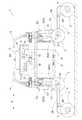
図1,2に本発明に係る作業車が示されている。この実施形態で、車体の前後方向を定義するときは、車体進行方向に沿って定義し、車体の左右方向を定義するときは、機体進行方向視で見た状態で左右を定義する。すなわち、図1に符号(A)で示す方向が車体前後方向であり、図2に符号(B)で示す方向が車体左右方向である。 1 and 2 show a work vehicle according to the present invention. In this embodiment, when defining the longitudinal direction of the vehicle body, it is defined along the traveling direction of the vehicle body, and when defining the lateral direction of the vehicle body, the left and right are defined in a state viewed from the vehicle body traveling direction. That is, the direction indicated by the reference numeral (A) in FIG. 1 is the vehicle front-rear direction, and the direction indicated by the reference numeral (B) in FIG. 2 is the vehicle left-right direction.
図1,2に示すように、作業車には、車両全体を支持する平面視で略矩形状の車両本体1と、複数(具体的には4個)の走行車輪2と、複数の走行車輪2の夫々に対応して設けられた複数の補助車輪3と、複数の走行車輪2を各別に位置変更自在に車両本体1に支持する車体支持部としての屈折リンク機構4と、屈折リンク機構4を変更操作可能な油圧駆動式の姿勢変更操作手段5と、複数の走行車輪2を各別に駆動する複数の油圧モータ6とが備えられている。屈折リンク機構4、走行車輪2及び補助車輪3の夫々が、車両本体1の前後両側に夫々左右一対ずつ備えられている。 As shown in FIGS. 1 and 2, the work vehicle includes a
車両本体1には、全体を支持する矩形枠状の車体フレーム7と、姿勢変更操作手段5に向けて作動油を送り出す油圧供給源8と、油圧供給源8から姿勢変更操作手段5に供給される作動油を制御する弁機構9とが備えられている。油圧供給源8は、詳述はしないが、エンジンと、エンジンによって駆動される油圧ポンプとを備えて、それらが一体的に連結されている。そして、油圧供給源8は、車体フレーム7の下側に連結された支持台10により載置支持され、車両本体1の下腹部に位置する状態で備えられている。油圧供給源8は、エンジンにて駆動される油圧ポンプにより、弁機構9を介して姿勢変更操作手段5に作動油を送り出し供給する。そして、図示はしていないが、支持台10を車体フレーム7から取り外すことにより、油圧供給源8と支持台10とを連結した状態で一体的に、車両本体1から横側方にスライドさせて取り外すことが可能であり、再度、支持台10を車体フレーム7に取り付けることにより、横側方にスライドさせて装着することが可能である。 The
弁機構9は、車体フレーム7の上側に載置支持される状態で備えられ、姿勢変更操作手段5に対する作動油の給排あるいは流量の調節等を行う複数の油圧制御弁11を備えている。弁機構9の上方は収納ケース12によって覆われている。収納ケース12の上側には、弁機構9の作動を制御する制御手段としての制御装置13が備えられている。 The valve mechanism 9 is provided in a state of being mounted and supported on the upper side of the vehicle body frame 7, and includes a plurality of
車体フレーム7の上側には、例えば、車両本体1が転倒したような場合に、収納ケース12に収納される弁機構9や上方に備えられる制御装置13等を保護するための外装フレーム14が備えられている。外装フレーム14は、前後両側に備えられ、棒状体が平面視で略U字形に曲げられ、且つ、側面視で略L字形に曲げられた形状となっており、車体フレーム7の前端部と後端部とに左右両側端部が取り付け固定されている。前後の外装フレーム14は、上部側が互いに近接するように設けられ、弁機構9や制御装置13等の外周側を覆う形状となっている。 On the upper side of the body frame 7, for example, when the
図8に示すように、前後の外装フレーム14を夫々、上部側が前後方向外方側に向かうように取付け、その上方に前後方向に幅広の載置板を取り付けると、荷物搬送用の台車として利用することができる。又、図9に示すように、外装フレーム14を上部側が前後方向一方側に向かうように取り付けることにより、外装フレーム14を作業者が手で握るための把手として利用することができる。 As shown in FIG. 8, the front and rear exterior frames 14 are mounted so that the upper side faces outward in the front-rear direction, and a wide mounting plate is mounted above the front and rear exterior frames 14 to be used as a truck for carrying cargo. can do. In addition, as shown in FIG. 9, by attaching the
次に、走行車輪2を車両本体1に支持するための支持構造について説明する。
複数(具体的には4つ)の走行車輪2は、屈折リンク機構4を介して車両本体1に対して各別に昇降自在に支持されている。屈折リンク機構4は、旋回操作手段としての旋回機構16を介して縦軸芯Y周りで回動可能に車体フレーム7に支持されている。Next, a support structure for supporting the traveling
A plurality of (specifically, four) traveling
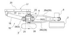
旋回機構16には、車体フレーム7に連結されるとともに、屈折リンク機構4を回動自在に支持する旋回支持部としての車体側支持部17(図3,4参照)と、屈折リンク機構4を旋回操作させる旋回用油圧シリンダ(以下、旋回シリンダと称する)18とが備えられている。 The
説明を加えると、図3,4に示すように、車体側支持部17は、車体フレーム7における横側箇所に備えられた上下一対の角筒状の前後向きフレーム体19に対して、横側外方から挟み込む状態で嵌め合い係合するとともに、取外し可能にボルト連結される連結部材20と、連結部材20の車体前後方向外方側箇所に位置する外方側枢支ブラケット21と、連結部材20の車体前後方向の内方側箇所に位置する内方側枢支ブラケット22と、外方側枢支ブラケット21に支持される縦向きの回動支軸23とを備え、回動支軸23の軸芯Y周りで回動自在に屈折リンク機構4を支持している。 In addition, as shown in FIGS. 3 and 4, the vehicle-body-
屈折リンク機構4には、上下方向の位置が固定された状態で且つ縦軸芯Y周りで回動自在に車体側支持部17に支持される基端部24と、一端部が基端部24の下部に横軸芯X1周りで回動自在に支持された第一リンク25と、一端部が第一リンク25の他端部に横軸芯X2周りで回動自在に支持され且つ他端部に走行車輪2が支持された第二リンク26とが備えられている。 The
説明を加えると、基端部24は、平面視で矩形枠状に設けられ、車体横幅方向内方側に偏倚した箇所において、回動支軸23を介して縦軸芯Y周りで回動自在に、車体側支持部17の外方側枢支ブラケット21に支持されている。旋回シリンダ18は、一端部が、内方側枢支ブラケット22に回動自在に連結され、他端部が、基端部24における回動支軸23に対して横方向に位置ずれした箇所に回動自在に連結されている。 In addition, the
基端部24の左右両側部に亘って第一リンク25の一端側に備えられた支持軸27が回動自在に架設支持され、第一リンク25は基端部24の下部に対して支持軸27の軸芯周りで回動自在に連結されている。 A
図4に示すように、第一リンク25は、基端側アーム部25bと他端側アーム部25aとを有している。第一リンク25の一端側箇所には、斜め上外方に向けて延びる基端側アーム部25bが一体的に形成されている。第一リンク25の他端側箇所には、斜め上外方に向けて延びる他端側アーム部25aが一体的に形成されている。 As shown in FIG. 4, the
図3に示すように、第二リンク26は、左右一対の帯板状の板体26a,26bを備えて平面視で二股状に形成されている。第二リンク26の第一リンク25に対する連結箇所は一対の板体26a,26bが間隔をあけている。一対の板体26a,26bで挟まれた領域に、第一リンク25と連結するための連結支軸28が回動自在に支持されている。第二リンク26の第一リンク25に対する連結箇所とは反対側の揺動側端部には走行車輪2が支持されている。図4に示すように、第二リンク26の揺動側端部は車両本体1から離れる方向に略L字状に延びるL字状延設部26Aが形成され、L字状延設部26Aの延設側端部に走行車輪2が支持されている。 As shown in FIG. 3, the
図2に示すように、走行車輪2は、屈折リンク機構4に対して左右方向の車体外方側に位置する状態で支持されている。具体的には、第二リンク26の揺動側端部において、左右方向の車体外方側に位置する状態で支持されている。油圧モータ6は、第二リンク26の揺動側端部において、左右方向の車体内方側(走行車輪2とは反対側)に位置する状態で支持されている。 As shown in FIG. 2, the traveling
複数の屈折リンク機構4の夫々に対応して、屈折リンク機構4の姿勢を各別に変更可能な姿勢変更操作手段5が備えられている。図3,4に示すように、姿勢変更操作手段5には、車両本体1に対する第一リンク25の揺動姿勢を変更可能な第一油圧シリンダ29と、第一リンク25に対する第二リンク26の揺動姿勢を変更可能な第二油圧シリンダ30とが備えられている。第一油圧シリンダ29及び第二油圧シリンダ30は、夫々、第一リンク25の近傍に集約して配置されている。 A posture changing
第一リンク25、第一油圧シリンダ29及び第二油圧シリンダ30が、平面視において、第二リンク26の一対の板体26a,26bの間に位置する状態で配備されている。第一油圧シリンダ29は、第一リンク25に対して車体前後方向内方側に位置して、第一リンク25の長手方向に沿うように設けられている。第一油圧シリンダ29の一端部が円弧状の第一連動部材31を介して基端部24の下部に連動連結されている。第一油圧シリンダ29の一端部は、別の第二連動部材32を介して第一リンク25の基端側箇所に連動連結されている。第一連動部材31及び第二連動部材32は、両側端部が夫々、相対回動可能に枢支連結されている。第一油圧シリンダ29の他端部は、第一リンク25に一体的に形成された他端側アーム部25aに連動連結されている。 The
第二油圧シリンダ30は、第一油圧シリンダ29とは反対側、すなわち、第一リンク25に対して車体前後方向外方側に位置して、第一リンク25の長手方向に略沿うように設けられている。第二油圧シリンダ30の一端部が第一リンク25の基端側に一体的に形成された基端側アーム部25bに連動連結されている。第二油圧シリンダ30の他端部は、第三連動部材34を介して第二リンク26の基端側箇所に一体的に形成されたアーム部35に連動連結されている。第二油圧シリンダ30の他端部は、別の第四連動部材36を介して第一リンク25の揺動端側箇所にも連動連結されている。第三連動部材34及び第四連動部材36は、両側端部が夫々、相対回動可能に枢支連結されている。 The second
第二油圧シリンダ30の作動を停止した状態で第一油圧シリンダ29を伸縮操作すると、第一リンク25、第二リンク26及び走行車輪2の夫々が、相対的な姿勢を一定に維持したまま一体的に、基端部24に対する枢支連結箇所の横軸芯X1周りで揺動する。第一油圧シリンダ29の作動を停止した状態で第二油圧シリンダ30を伸縮操作すると、第一リンク25の姿勢が一定に維持されたまま、第二リンク26及び走行車輪2が、一体的に、第一リンク25と第二リンク26との連結箇所の横軸芯X2周りで揺動する。 When the first
複数の屈折リンク機構4夫々の中間屈折部に自由回転自在に補助車輪3が支持されている。補助車輪3は走行車輪2と略同じ外径の車輪にて構成されている。第一リンク25と第二リンク26とを枢支連結する連結支軸28が、第二リンク26よりも車体横幅方向外方側に突出するように延長形成されている。連結支軸28の延長突出箇所に補助車輪3が回動自在に支持されている。 The
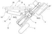
図5,6に示すように、屈折リンク機構4、走行車輪2、補助車輪3、及び、姿勢変更操作手段5の夫々が、一体的に、回動支軸23の軸芯Y周りで回動自在に外方側枢支ブラケット21に支持されている。そして、旋回シリンダ18を伸縮させることにより、それらが一体的に回動操作される。走行車輪2が前後方向に向く直進状態から左旋回方向及び右旋回方向に夫々、約45度ずつ旋回操作させることができる。 As shown in FIGS. 5 and 6, each of the
尚、図示はしないが、前後向きフレーム体19に対する連結部材20のボルト連結を解除すると、旋回機構16、屈折リンク機構4、走行車輪2、補助車輪3、及び、姿勢変更操作手段5の夫々が、一体的に組付けられた状態で、車両本体1から取り外すことができる。又、前後向きフレーム体19に対して連結部材20をボルト連結することで、上記各装置が一体的に組付けられた状態で、車両本体1に取付けることができる。 Although not shown, when the bolt connection of the connecting
油圧供給源8から弁機構9を介して複数の屈折リンク機構4夫々の第一油圧シリンダ29及び第二油圧シリンダ30に作動油が供給される。弁機構9では油圧制御弁11により作動油の給排が行われて、第一油圧シリンダ29及び第二油圧シリンダ30を伸縮操作させることができる。油圧制御弁11は制御装置13によって制御される。 Hydraulic oil is supplied from the
又、油圧モータ6に対応する油圧制御弁11により作動油の流量調整が行われることで、油圧モータ6すなわち走行車輪2の回転速度を変更することができる。油圧制御弁11は、手動操作にて入力される制御情報あるいは予め設定記憶されている制御情報等に基づいて制御装置13によって制御される。 In addition, by adjusting the flow rate of the hydraulic oil by the
この作業車は種々のセンサを備える。具体的には、図1及び図7に示すように、4つの第二油圧シリンダ30の夫々について、ヘッド側圧力センサS1及びキャップ側圧力センサS2を備える。ヘッド側圧力センサS1は、第二油圧シリンダ30のヘッド側室の油圧を検出する。キャップ側圧力センサS2は、第二油圧シリンダ30のキャップ側室の油圧を検出する。各圧力センサS1,S2の検出結果は制御装置13に入力される。 This work vehicle includes various sensors. Specifically, as shown in FIGS. 1 and 7, each of the four second
図7に示すように、4つの第一油圧シリンダ29及び4つの第二油圧シリンダ30の夫々について、伸縮操作量を検出可能なストロークセンサS3が備えられている。各油圧シリンダ29,30の伸縮操作量は、操作対象である第一リンク25及び第二リンク26の揺動位置に対応する検出値であり、ストロークセンサS3は位置検出センサに相当する。各ストロークセンサS3の検出結果は制御装置13に入力される。 As shown in FIG. 7, each of the four first
尚、各圧力センサS1,S2の取り付け位置は上記した位置に限られるものではない。各圧力センサS1,S2は、対応するキャップ側室又はヘッド側室の油圧を検出(推定)可能であればよく、弁機構9から対応するキャップ側室又はヘッド側室の間の配管に設けられてもよい。 The mounting positions of the pressure sensors S1 and S2 are not limited to the positions described above. Each of the pressure sensors S1 and S2 only needs to be able to detect (estimate) the oil pressure of the corresponding cap-side chamber or head-side chamber, and may be provided in a pipe from the valve mechanism 9 to the corresponding cap-side chamber or head-side chamber.
これらのセンサS1,S2の検出結果に基づいて、車両本体1を支持するために必要な推力が算出され、その結果に基づいて、それぞれの第二油圧シリンダ30への作動油の供給が制御される。 The thrust required to support the
車両本体1には、例えば、三軸加速度センサ等からなる加速度センサS5が備えられている。加速度センサS5の検出結果に基づき、車両本体1の前後左右の傾きが検知され、その結果に基づいて車両本体1の姿勢が制御される。つまり、車両本体1の姿勢が目標の姿勢となるよう、それぞれの第一油圧シリンダ29及び第二油圧シリンダ30への作動油の供給が制御される。 The
走行車輪2には、油圧モータ6により駆動される走行車輪2の回転速度を検出する回転センサS6が備えられている。回転センサS6にて検出された走行車輪2の回転速度に基づいて、走行車輪2の回転速度が目標の値となるように、油圧モータ6への作動油の供給が制御される。 The traveling
上述したように、油圧駆動式の姿勢変更操作手段5としての油圧シリンダ29,30により、屈折リンク機構4の姿勢を変更操作する構成であり、しかも、走行駆動も油圧モータ6にて行う構成であるから、水分や細かな塵埃等による影響を受け難く、農作業に適したものになる。 As described above, the configuration is such that the attitude of the
この作業車は、図1に示すように、4個の走行車輪2が全て接地し且つ4個の補助車輪3が全て地面から浮上する4輪走行状態が通常の走行形態である。尚、詳述はしないが、走行形態としては、この形態以外に、屈折リンク機構4を姿勢変更することにより、種々の走行形態を採ることができる。 In this work vehicle, as shown in FIG. 1, a normal traveling mode is a four-wheel traveling state in which all four traveling
次に、4輪走行形態における車両本体1の姿勢変更制御について説明する。
図7に、制御ブロック図を示している。詳述はしないが、制御装置13は、手動操作にて入力される制御情報あるいは予め設定されて記憶されている制御情報等に基づいて、そのときの作業状況に応じて、車両本体1の姿勢を適切な状態にするように制御を実行する。図示はしていないが、制御装置13は、複数の油圧モータ6に対する作動油の制御も行っているNext, the attitude change control of the
FIG. 7 shows a control block diagram. Although not described in detail, the
制御装置13は、作業車が走行停止している状態では、4個の第一油圧シリンダ29及び4個の第二油圧シリンダ30について、各油圧シリンダ29,30に備えられているストロークセンサS3にて検出される伸縮操作量が目標とする姿勢に対応する検出値になるように、油圧制御弁11を切り換えて各油圧シリンダ29,30を操作させる位置制御を実行する。 When the traveling vehicle is stopped, the
作業車が凹凸の多い不整地等を走行するときは、4個の第一油圧シリンダ29については、各油圧シリンダ29に備えられているストロークセンサS3にて検出される伸縮操作量が目標とする姿勢に対応する検出値になるように、各油圧シリンダ29を操作させるように油圧制御弁11を切り換える位置制御を実行する。それに対して、4個の第二油圧シリンダ30については、上記各圧力センサS1,S2の検出情報に基づいて、作動を制御する。具体的には、ヘッド側圧力センサS1の検出値とキャップ側圧力センサS2の検出値とに基づき、第二油圧シリンダ30の推力が算出される。そして、検出される推力が予め設定されて記憶されている目標値になるように、油圧制御弁11を切り換えて第二油圧シリンダ30の作動を制御する。 When the work vehicle travels on uneven terrain with a lot of irregularities, for the four first
さらに、制御装置13は、旋回操作が指令されると、旋回シリンダ18に備えられているストロークセンサS3にて検出される伸縮操作量が目標とする旋回角に対応する検出値になるように、油圧制御弁11を切り換えて旋回シリンダ18を操作させる旋回制御を実行する。 Further, when the turning operation is commanded, the
制御装置13は、作業車が移動走行しているときに、旋回制御を実行して旋回走行する場合、前部側に位置する左右の走行車輪2又は後部側に位置する左右の走行車輪2のいずれかを向き変更操作するときは、車両本体1の重心位置が、車体前後方向のうち向き変更操作が行われる側とは反対側に向けて移動するように、姿勢変更操作手段5の作動を制御する。 The
具体的には、制御装置13は、車体前後方向のうち向き変更操作が行われる側に位置する屈折リンク機構4が、接地している走行車輪2に対して車両本体1を離間させるように、姿勢変更操作手段5を作動させ、且つ、車体前後方向のうち向き変更操作が行われる側とは反対側に位置する屈折リンク機構4が、接地している走行車輪2に対して車両本体1を近づけるように、姿勢変更操作手段5を作動させる。 Specifically, the
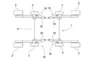
説明を加えると、例えば、図10に示すように、車体進行方向前部側の左右の走行車輪2が左方向に向き変更するように旋回シリンダ18を作動させている場合、図11に示すように、車体前部側の走行車輪2を支持する左右の屈折リンク機構4について、第二リンク26の基端側が上方に向かって揺動するように、左前側及び右前側夫々の第二油圧シリンダ30を作動させるとともに、車体後部側の走行車輪2を支持する左右の屈折リンク機構4について、第二リンク26の基端側が下方に向かって揺動するように、左後側及び右後側夫々の第二油圧シリンダ30を作動させる。その結果、車両本体1は、前部側が上昇し且つ後部側が下降する前後傾斜姿勢に切り換わる。そうすると、図12及び図13に示すように、直進状態で走行している場合に比べて、車両本体1の重心位置が、車体前後方向のうち向き変更操作が行われる側とは反対側に向けて移動することになる。 In addition, for example, as shown in FIG. 10, when the turning
上記したような前後傾斜姿勢になることにより、旋回操作される前部側の走行車輪2に対する車両本体1の荷重負担、言い換えると、向き変更するときの移動抵抗となる走行車輪2が地面から受ける負荷を軽減させることができ、円滑に向き変更操作させることが可能となる。 By adopting the above-described front-rear inclination posture, the load of the
〔別実施形態〕
(1)上記実施形態では、前後方向のうち向き変更操作が行われる側に位置する屈折リンク機構4が、接地している走行車輪2に対して車両本体1を離間させ、反対側に位置する屈折リンク機構4が、接地している走行車輪2に対して車両本体1を近づけるように、姿勢変更操作手段5が作動する構成としたが、この構成に代えて、向き変更操作が行われる側から反対側に向けて車両本体1に備えられる重量物、例えば、エンジン等を車体前後方向にスライド移動させることにより重心位置を移動させるようにしてもよい。[Another embodiment]
(1) In the above embodiment, the
(2)上記実施形態では、旋回シリンダ18の伸縮操作量を検出するストロークセンサS3が備えられる構成としたが、この構成に代えて、第一リンク25の揺動支点に設けられた回転式のポテンショメータにより伸縮操作量を検出する構成としてもよい。(2) In the above embodiment, the stroke sensor S3 for detecting the amount of expansion / contraction operation of the turning
(3)上記実施形態では、旋回機構16(旋回操作手段)に旋回シリンダ18が備えられる構成としたが、電動モータや油圧モータにより旋回操作させる構成としてもよい。(3) In the above embodiment, the turning mechanism 16 (turning operation means) is provided with the turning
(4)上記実施形態では、補助車輪3が自由回転自在に支持される構成としたが、補助車輪3を回転駆動する構成としてもよく、このような補助車輪3を備えない構成としてもよい。(4) In the above embodiment, the
(5)上記実施形態では、走行車輪2が油圧モータ6により駆動される構成としたが、この構成に代えて、例えば、エンジンの動力がチェーン伝動機構等の機械式伝動機構を介して走行車輪2に供給される構成でもよい。(5) In the above-described embodiment, the traveling
本発明は、凹凸の多い路面を走行するのに適した作業車に適用できる。 INDUSTRIAL APPLICABILITY The present invention can be applied to a work vehicle suitable for traveling on a road surface having a lot of unevenness.
1 車両本体
2 走行車輪
4 屈折リンク機構
5 姿勢変更操作手段
13 制御手段
16 旋回操作手段
17 旋回支持部
18 旋回シリンダ
25 第一リンク
26 第二リンク
DESCRIPTION OF
Claims (3)
Translated fromJapanese複数の前記走行車輪を各別に昇降自在に前記車両本体に支持する複数の屈折リンク機構と、
複数の前記屈折リンク機構の姿勢を各別に変更可能な姿勢変更操作手段と、
複数の前記屈折リンク機構の夫々を縦軸芯周りで向き変更可能に前記車両本体に支持する複数の旋回操作手段と、
前記姿勢変更操作手段と前記旋回操作手段の作動を制御する制御手段とが備えられ、
前記制御手段は、
前部側に位置する左右の前記走行車輪又は後部側に位置する左右の前記走行車輪のいずれかを向き変更操作するときは、前記車両本体の重心位置が、車体前後方向のうち向き変更操作が行われる側とは反対側に向けて移動するように、前記姿勢変更操作手段の作動を制御する作業車。A plurality of traveling wheels located on each of the front and rear sides on the left and right sides of the vehicle body,
A plurality of refraction link mechanisms for supporting the plurality of traveling wheels individually on the vehicle body so as to be capable of ascending and descending,
Attitude change operation means capable of individually changing the attitude of the plurality of refraction link mechanisms,
A plurality of turning operation means for supporting each of the plurality of refraction link mechanisms on the vehicle body so as to be able to change their orientation around a longitudinal axis,
Control means for controlling the operation of the attitude change operation means and the turning operation means,
The control means includes:
When changing the direction of one of the left and right running wheels located on the front side or the left and right running wheels located on the rear side, the center of gravity position of the vehicle body may be changed in the vehicle longitudinal direction. A work vehicle that controls the operation of the attitude change operation means so as to move toward the side opposite to the side where the operation is performed.
車体前後方向のうち向き変更操作が行われる側に位置する前記屈折リンク機構が、その屈折リンク機構により支持され且つ接地している前記走行車輪に対して前記車両本体を離間させるように、前記姿勢変更操作手段を作動させ、且つ、
車体前後方向のうち向き変更操作が行われる側とは反対側に位置する前記屈折リンク機構が、その屈折リンク機構により支持され且つ接地している前記走行車輪に対して前記車両本体を近づけるように、前記姿勢変更操作手段を作動させる請求項1に記載の作業車。The control means includes:
The attitude of the bending link mechanism, which is located on the side of the vehicle body front-rear direction in which the direction changing operation is performed, such that the vehicle body is separated from the traveling wheel supported by the bending link mechanism and grounded; Activating the change operation means, and
The refraction link mechanism, which is located on the side opposite to the side on which the direction changing operation is performed in the vehicle longitudinal direction, moves the vehicle body closer to the traveling wheel supported by the refraction link mechanism and grounded. The work vehicle according to claim 1, wherein the posture changing operation means is operated.
一端部が前記車両本体に横軸芯周りで回動自在に支持された第一リンクと、一端部が前記第一リンクの他端部に横軸芯周りで回動自在に枢支連結され且つ他端部に前記走行車輪が支持された第二リンクとが備えられ、
前記旋回操作手段に、
前記第一リンクを前記縦軸芯周りで向き変更可能に前記車両本体に支持する旋回支持部と、前記第一リンクと前記第二リンクとを一体的に前記縦軸芯周りで向き変更操作する旋回操作用の油圧シリンダとが備えられている請求項1又は2に記載の作業車。In the refraction link mechanism,
A first link having one end rotatably supported on the vehicle body around a horizontal axis, and one end being pivotally connected to the other end of the first link rotatably around the horizontal axis; and The other end is provided with a second link on which the traveling wheel is supported,
In the turning operation means,
A turning support portion that supports the first link on the vehicle body so as to be able to change the direction around the vertical axis, and performs a direction changing operation about the vertical axis integrally with the first link and the second link; The work vehicle according to claim 1 or 2, further comprising a hydraulic cylinder for turning operation.
Priority Applications (5)
| Application Number | Priority Date | Filing Date | Title |
|---|---|---|---|
| JP2018119980AJP6899801B2 (en) | 2018-06-25 | 2018-06-25 | Work platform |
| PCT/JP2019/023212WO2020004024A1 (en) | 2018-06-25 | 2019-06-12 | Working vehicle |
| US17/047,807US11498632B2 (en) | 2018-06-25 | 2019-06-12 | Work vehicle |
| CN201980031218.4ACN112119004B (en) | 2018-06-25 | 2019-06-12 | Working vehicle |
| EP19824511.0AEP3812250A4 (en) | 2018-06-25 | 2019-06-12 | COMMERCIAL VEHICLE |
Applications Claiming Priority (1)
| Application Number | Priority Date | Filing Date | Title |
|---|---|---|---|
| JP2018119980AJP6899801B2 (en) | 2018-06-25 | 2018-06-25 | Work platform |
Publications (2)
| Publication Number | Publication Date |
|---|---|
| JP2020001442Atrue JP2020001442A (en) | 2020-01-09 |
| JP6899801B2 JP6899801B2 (en) | 2021-07-07 |
Family
ID=69098221
Family Applications (1)
| Application Number | Title | Priority Date | Filing Date |
|---|---|---|---|
| JP2018119980AActiveJP6899801B2 (en) | 2018-06-25 | 2018-06-25 | Work platform |
Country Status (1)
| Country | Link |
|---|---|
| JP (1) | JP6899801B2 (en) |
Cited By (6)
| Publication number | Priority date | Publication date | Assignee | Title |
|---|---|---|---|---|
| WO2022124158A1 (en)* | 2020-12-11 | 2022-06-16 | 株式会社クボタ | Work vehicle |
| JP2023000769A (en)* | 2021-06-18 | 2023-01-04 | 株式会社クボタ | Working vehicle |
| JP2023000768A (en)* | 2021-06-18 | 2023-01-04 | 株式会社クボタ | Working vehicle |
| JP2023092154A (en)* | 2021-12-21 | 2023-07-03 | 株式会社クボタ | work vehicle |
| JP2023092155A (en)* | 2021-12-21 | 2023-07-03 | 株式会社クボタ | work vehicle |
| JP2024004326A (en)* | 2022-06-28 | 2024-01-16 | 株式会社クボタ | work vehicle |
Citations (2)
| Publication number | Priority date | Publication date | Assignee | Title |
|---|---|---|---|---|
| JPS61500604A (en)* | 1983-12-02 | 1986-04-03 | リツトマン, ア−ヴイン ジエ−. | prime mover |
| JPH09501630A (en)* | 1993-08-19 | 1997-02-18 | デ オリベイラ,フェルナンド ホセ ネリー | System to be applied to universal ground vehicles with traction means attached to articulated arms |
- 2018
- 2018-06-25JPJP2018119980Apatent/JP6899801B2/enactiveActive
Patent Citations (2)
| Publication number | Priority date | Publication date | Assignee | Title |
|---|---|---|---|---|
| JPS61500604A (en)* | 1983-12-02 | 1986-04-03 | リツトマン, ア−ヴイン ジエ−. | prime mover |
| JPH09501630A (en)* | 1993-08-19 | 1997-02-18 | デ オリベイラ,フェルナンド ホセ ネリー | System to be applied to universal ground vehicles with traction means attached to articulated arms |
Cited By (15)
| Publication number | Priority date | Publication date | Assignee | Title |
|---|---|---|---|---|
| JP7412322B2 (en) | 2020-12-11 | 2024-01-12 | 株式会社クボタ | work vehicle |
| JP2022093116A (en)* | 2020-12-11 | 2022-06-23 | 株式会社クボタ | Work vehicle |
| US12427824B2 (en) | 2020-12-11 | 2025-09-30 | Kubota Corporation | Work vehicle |
| WO2022124158A1 (en)* | 2020-12-11 | 2022-06-16 | 株式会社クボタ | Work vehicle |
| EP4261114A4 (en)* | 2020-12-11 | 2024-11-06 | Kubota Corporation | WORK VEHICLE |
| JP2023000768A (en)* | 2021-06-18 | 2023-01-04 | 株式会社クボタ | Working vehicle |
| JP7466498B2 (en) | 2021-06-18 | 2024-04-12 | 株式会社クボタ | Work vehicle |
| JP7466499B2 (en) | 2021-06-18 | 2024-04-12 | 株式会社クボタ | Work vehicle |
| JP2023000769A (en)* | 2021-06-18 | 2023-01-04 | 株式会社クボタ | Working vehicle |
| JP2023092155A (en)* | 2021-12-21 | 2023-07-03 | 株式会社クボタ | work vehicle |
| JP2023092154A (en)* | 2021-12-21 | 2023-07-03 | 株式会社クボタ | work vehicle |
| JP7595560B2 (en) | 2021-12-21 | 2024-12-06 | 株式会社クボタ | Work vehicle |
| JP7607550B2 (en) | 2021-12-21 | 2024-12-27 | 株式会社クボタ | Work vehicle |
| JP2024004326A (en)* | 2022-06-28 | 2024-01-16 | 株式会社クボタ | work vehicle |
| JP7720817B2 (en) | 2022-06-28 | 2025-08-08 | 株式会社クボタ | Work vehicle |
Also Published As
| Publication number | Publication date |
|---|---|
| JP6899801B2 (en) | 2021-07-07 |
Similar Documents
| Publication | Publication Date | Title |
|---|---|---|
| JP6899801B2 (en) | Work platform | |
| WO2018181459A1 (en) | Work vehicle | |
| JP6899799B2 (en) | Work platform | |
| CN112119004B (en) | Working vehicle | |
| WO2019131522A1 (en) | Work vehicle | |
| US11767071B2 (en) | Work vehicle | |
| CN110494349B (en) | Working vehicle | |
| JP7117989B2 (en) | work vehicle | |
| JP6758278B2 (en) | Work vehicle | |
| JP6745750B2 (en) | Work vehicle | |
| JP2020001443A (en) | Work vehicle | |
| JP6843040B2 (en) | Work platform | |
| WO2022124158A1 (en) | Work vehicle | |
| JP6937725B2 (en) | Work platform | |
| JP6832841B2 (en) | Work vehicle | |
| JP6758277B2 (en) | Work vehicle | |
| JP6899800B2 (en) | Work platform | |
| WO2019131573A1 (en) | Work vehicle | |
| JP6739387B2 (en) | Work vehicle | |
| JP6745751B2 (en) | Work vehicle | |
| JP7419222B2 (en) | work vehicle | |
| JP6701112B2 (en) | Work vehicle | |
| JP7482765B2 (en) | Work vehicle | |
| JP6701111B2 (en) | Work vehicle | |
| JP7466499B2 (en) | Work vehicle |
Legal Events
| Date | Code | Title | Description |
|---|---|---|---|
| A621 | Written request for application examination | Free format text:JAPANESE INTERMEDIATE CODE: A621 Effective date:20200624 | |
| A131 | Notification of reasons for refusal | Free format text:JAPANESE INTERMEDIATE CODE: A131 Effective date:20210224 | |
| A521 | Request for written amendment filed | Free format text:JAPANESE INTERMEDIATE CODE: A523 Effective date:20210419 | |
| TRDD | Decision of grant or rejection written | ||
| A01 | Written decision to grant a patent or to grant a registration (utility model) | Free format text:JAPANESE INTERMEDIATE CODE: A01 Effective date:20210518 | |
| A61 | First payment of annual fees (during grant procedure) | Free format text:JAPANESE INTERMEDIATE CODE: A61 Effective date:20210615 | |
| R150 | Certificate of patent or registration of utility model | Ref document number:6899801 Country of ref document:JP Free format text:JAPANESE INTERMEDIATE CODE: R150 |