JP2019533564A - Bone plate suture connection system - Google Patents
Bone plate suture connection systemDownload PDFInfo
- Publication number
- JP2019533564A JP2019533564AJP2019543168AJP2019543168AJP2019533564AJP 2019533564 AJP2019533564 AJP 2019533564AJP 2019543168 AJP2019543168 AJP 2019543168AJP 2019543168 AJP2019543168 AJP 2019543168AJP 2019533564 AJP2019533564 AJP 2019533564A
- Authority
- JP
- Japan
- Prior art keywords
- proximal
- suture
- hole
- bone plate
- connector
- Prior art date
- Legal status (The legal status is an assumption and is not a legal conclusion. Google has not performed a legal analysis and makes no representation as to the accuracy of the status listed.)
- Ceased
Links
Images


Classifications
- A—HUMAN NECESSITIES
- A61—MEDICAL OR VETERINARY SCIENCE; HYGIENE
- A61B—DIAGNOSIS; SURGERY; IDENTIFICATION
- A61B17/00—Surgical instruments, devices or methods
- A61B17/04—Surgical instruments, devices or methods for suturing wounds; Holders or packages for needles or suture materials
- A61B17/0401—Suture anchors, buttons or pledgets, i.e. means for attaching sutures to bone, cartilage or soft tissue; Instruments for applying or removing suture anchors
- A—HUMAN NECESSITIES
- A61—MEDICAL OR VETERINARY SCIENCE; HYGIENE
- A61B—DIAGNOSIS; SURGERY; IDENTIFICATION
- A61B17/00—Surgical instruments, devices or methods
- A61B17/56—Surgical instruments or methods for treatment of bones or joints; Devices specially adapted therefor
- A61B17/58—Surgical instruments or methods for treatment of bones or joints; Devices specially adapted therefor for osteosynthesis, e.g. bone plates, screws or setting implements
- A61B17/68—Internal fixation devices, including fasteners and spinal fixators, even if a part thereof projects from the skin
- A61B17/80—Cortical plates, i.e. bone plates; Instruments for holding or positioning cortical plates, or for compressing bones attached to cortical plates
- A—HUMAN NECESSITIES
- A61—MEDICAL OR VETERINARY SCIENCE; HYGIENE
- A61B—DIAGNOSIS; SURGERY; IDENTIFICATION
- A61B17/00—Surgical instruments, devices or methods
- A61B17/56—Surgical instruments or methods for treatment of bones or joints; Devices specially adapted therefor
- A61B17/58—Surgical instruments or methods for treatment of bones or joints; Devices specially adapted therefor for osteosynthesis, e.g. bone plates, screws or setting implements
- A61B17/68—Internal fixation devices, including fasteners and spinal fixators, even if a part thereof projects from the skin
- A61B17/82—Internal fixation devices, including fasteners and spinal fixators, even if a part thereof projects from the skin for bone cerclage
- A—HUMAN NECESSITIES
- A61—MEDICAL OR VETERINARY SCIENCE; HYGIENE
- A61B—DIAGNOSIS; SURGERY; IDENTIFICATION
- A61B17/00—Surgical instruments, devices or methods
- A61B17/56—Surgical instruments or methods for treatment of bones or joints; Devices specially adapted therefor
- A61B17/58—Surgical instruments or methods for treatment of bones or joints; Devices specially adapted therefor for osteosynthesis, e.g. bone plates, screws or setting implements
- A61B17/88—Osteosynthesis instruments; Methods or means for implanting or extracting internal or external fixation devices
- A61B17/8875—Screwdrivers, spanners or wrenches
- A61B17/8877—Screwdrivers, spanners or wrenches characterised by the cross-section of the driver bit
- A61B17/8883—Screwdrivers, spanners or wrenches characterised by the cross-section of the driver bit the driver bit acting on the periphery of the screw head
- A—HUMAN NECESSITIES
- A61—MEDICAL OR VETERINARY SCIENCE; HYGIENE
- A61B—DIAGNOSIS; SURGERY; IDENTIFICATION
- A61B17/00—Surgical instruments, devices or methods
- A61B17/56—Surgical instruments or methods for treatment of bones or joints; Devices specially adapted therefor
- A61B17/58—Surgical instruments or methods for treatment of bones or joints; Devices specially adapted therefor for osteosynthesis, e.g. bone plates, screws or setting implements
- A61B17/68—Internal fixation devices, including fasteners and spinal fixators, even if a part thereof projects from the skin
- A61B17/80—Cortical plates, i.e. bone plates; Instruments for holding or positioning cortical plates, or for compressing bones attached to cortical plates
- A61B17/8052—Cortical plates, i.e. bone plates; Instruments for holding or positioning cortical plates, or for compressing bones attached to cortical plates immobilised relative to screws by interlocking form of the heads and plate holes, e.g. conical or threaded
- A61B17/8057—Cortical plates, i.e. bone plates; Instruments for holding or positioning cortical plates, or for compressing bones attached to cortical plates immobilised relative to screws by interlocking form of the heads and plate holes, e.g. conical or threaded the interlocking form comprising a thread
- A—HUMAN NECESSITIES
- A61—MEDICAL OR VETERINARY SCIENCE; HYGIENE
- A61B—DIAGNOSIS; SURGERY; IDENTIFICATION
- A61B17/00—Surgical instruments, devices or methods
- A61B17/04—Surgical instruments, devices or methods for suturing wounds; Holders or packages for needles or suture materials
- A61B17/0401—Suture anchors, buttons or pledgets, i.e. means for attaching sutures to bone, cartilage or soft tissue; Instruments for applying or removing suture anchors
- A61B2017/0409—Instruments for applying suture anchors
- A—HUMAN NECESSITIES
- A61—MEDICAL OR VETERINARY SCIENCE; HYGIENE
- A61B—DIAGNOSIS; SURGERY; IDENTIFICATION
- A61B17/00—Surgical instruments, devices or methods
- A61B17/04—Surgical instruments, devices or methods for suturing wounds; Holders or packages for needles or suture materials
- A61B17/0401—Suture anchors, buttons or pledgets, i.e. means for attaching sutures to bone, cartilage or soft tissue; Instruments for applying or removing suture anchors
- A61B2017/0414—Suture anchors, buttons or pledgets, i.e. means for attaching sutures to bone, cartilage or soft tissue; Instruments for applying or removing suture anchors having a suture-receiving opening, e.g. lateral opening
- A—HUMAN NECESSITIES
- A61—MEDICAL OR VETERINARY SCIENCE; HYGIENE
- A61B—DIAGNOSIS; SURGERY; IDENTIFICATION
- A61B17/00—Surgical instruments, devices or methods
- A61B17/04—Surgical instruments, devices or methods for suturing wounds; Holders or packages for needles or suture materials
- A61B17/0401—Suture anchors, buttons or pledgets, i.e. means for attaching sutures to bone, cartilage or soft tissue; Instruments for applying or removing suture anchors
- A61B2017/044—Suture anchors, buttons or pledgets, i.e. means for attaching sutures to bone, cartilage or soft tissue; Instruments for applying or removing suture anchors with a threaded shaft, e.g. screws
- A—HUMAN NECESSITIES
- A61—MEDICAL OR VETERINARY SCIENCE; HYGIENE
- A61B—DIAGNOSIS; SURGERY; IDENTIFICATION
- A61B17/00—Surgical instruments, devices or methods
- A61B17/04—Surgical instruments, devices or methods for suturing wounds; Holders or packages for needles or suture materials
- A61B17/0401—Suture anchors, buttons or pledgets, i.e. means for attaching sutures to bone, cartilage or soft tissue; Instruments for applying or removing suture anchors
- A61B2017/0446—Means for attaching and blocking the suture in the suture anchor
- A61B2017/0456—Surface features on the anchor, e.g. ribs increasing friction between the suture and the anchor
Landscapes
- Health & Medical Sciences (AREA)
- Surgery (AREA)
- Life Sciences & Earth Sciences (AREA)
- Orthopedic Medicine & Surgery (AREA)
- Heart & Thoracic Surgery (AREA)
- Nuclear Medicine, Radiotherapy & Molecular Imaging (AREA)
- Engineering & Computer Science (AREA)
- Biomedical Technology (AREA)
- Medical Informatics (AREA)
- Molecular Biology (AREA)
- Animal Behavior & Ethology (AREA)
- General Health & Medical Sciences (AREA)
- Public Health (AREA)
- Veterinary Medicine (AREA)
- Neurology (AREA)
- Rheumatology (AREA)
- Surgical Instruments (AREA)
Abstract
Translated fromJapaneseDescription
Translated fromJapanese (優先権の主張)
本出願は、2016年10月25日付で出願された米国特許仮出願第62/412,683号の優先権を主張する。上記出願の全開示内容は、参照により本明細書に明示的に援用される。(Claiming priority)
This application claims priority from US Provisional Application No. 62 / 412,683, filed October 25, 2016. The entire disclosure of the above application is expressly incorporated herein by reference.
大きな骨の欠損は、多くの場合、治癒を助けるためにインプラントで治療される。骨プレートは、多くの場合、例えば骨折部位において、骨の損傷部分又は弱化部分を安定化させるために利用される。骨プレートは、様々な方法のいずれかを用いて、標的領域内に配置されてよい。例えば、骨プレートは一般に、骨固定要素(ねじ及び/又はピンなど)が骨に挿入されて、プレートを骨の標的部分に固定する開口部を含んでよい。しかしながら、いくつかの状況では、骨片は更なる安定化を必要とする。そのような場合、骨プレート及び固定要素に加えて縫合糸を使用して、骨片を安定化させ、以前に達成された骨折の整復を維持することが有益であり得る。縫合糸は、多くの場合、プレートが骨に固定される前に、プレートの孔に縫合糸を通すことによって骨プレートに固定される。しかしながら、このように骨プレートに縫合糸を取り付けることは、特にプレートが骨に取り付けられた後に、外科医が利用可能な縫合糸取り付け位置を制限することが多い。 Large bone defects are often treated with implants to aid healing. Bone plates are often used to stabilize damaged or weakened portions of bone, for example at the fracture site. The bone plate may be placed in the target area using any of a variety of methods. For example, a bone plate may generally include an opening through which bone fixation elements (such as screws and / or pins) are inserted into the bone to secure the plate to the target portion of the bone. However, in some situations, the bone fragments require further stabilization. In such cases, it may be beneficial to use sutures in addition to the bone plate and fixation elements to stabilize the bone fragments and maintain the previously achieved fracture reduction. The suture is often secured to the bone plate by passing the suture through a hole in the plate before the plate is secured to the bone. However, attaching a suture to a bone plate in this manner often limits the suture attachment locations available to the surgeon, particularly after the plate is attached to the bone.
本発明は、骨プレート及び固定ねじに加えて、縫合糸を使用して骨片を安定化させるための縫合糸接続装置及び方法に関する。 The present invention relates to a suture connection apparatus and method for stabilizing bone fragments using sutures in addition to bone plates and fixation screws.
一態様では、縫合糸接続システムが提供される。このシステムは、骨プレートの孔に挿入されるように構成されている本体を含む縫合糸コネクタを含む。本体は、近位端と、遠位端と、骨プレートの厚さに実質的に対応する、近位端と遠位端との間に延在する長さと、側壁と、を有する。コネクタ本体は、縫合糸コネクタを骨プレートに固定するためにねじ付きである。縫合糸コネクタはまた、側壁から内側に延在して近位係合部を画定する、少なくとも1つの凹部を含む。縫合糸コネクタは、縫合糸を受容するように構成されており、近位係合部を通って延在し、凹部に対して開口している貫通孔を更に含む。このシステムはまた、ドライバを含む。このドライバは、ドライバの長手方向軸に沿って近位端から遠位端まで延在する細長いロッドを含む。ドライバはまた、ロッドの遠位端に連結された係合要素を含み、この係合要素は、近位係合部を係合するように構成されている少なくとも1つの突起を有する。一実施形態では、係合要素は、2つの突起を含む。別の実施形態では、突起は切り欠き部を含む。更なる実施形態では、切り欠き部は、遠位突起面から丸みを帯びた近位切り欠き縁部まで延在し、近位切り欠き縁部は、貫通孔の近位縁部と位置合わせされ、その結果、突起のいずれの部分も孔を塞がない。更なる実施形態では、近位係合部は、2つの凹部を含む。別の実施形態では、突起は近位係合部の側面を係合する。更なる実施形態では、縫合糸コネクタは、縫合糸コネクタのいずれの部分も骨プレートの上面又は下面を越えて延在しないように、骨プレート孔内で同一平面に位置する寸法及び形状である。 In one aspect, a suture connection system is provided. The system includes a suture connector that includes a body configured to be inserted into a hole in a bone plate. The body has a proximal end, a distal end, a length extending between the proximal end and the distal end substantially corresponding to the thickness of the bone plate, and a sidewall. The connector body is threaded to secure the suture connector to the bone plate. The suture connector also includes at least one recess that extends inwardly from the sidewall and defines a proximal engagement portion. The suture connector is configured to receive a suture and further includes a through hole extending through the proximal engagement portion and opening to the recess. The system also includes a driver. The driver includes an elongated rod that extends from the proximal end to the distal end along the longitudinal axis of the driver. The driver also includes an engagement element coupled to the distal end of the rod, the engagement element having at least one protrusion configured to engage the proximal engagement portion. In one embodiment, the engagement element includes two protrusions. In another embodiment, the protrusion includes a notch. In a further embodiment, the notch extends from the distal projection surface to a rounded proximal notch edge, and the proximal notch edge is aligned with the proximal edge of the through-hole. As a result, any part of the protrusion does not block the hole. In a further embodiment, the proximal engagement portion includes two recesses. In another embodiment, the protrusion engages the side of the proximal engagement portion. In further embodiments, the suture connector is sized and shaped to be coplanar within the bone plate hole such that no portion of the suture connector extends beyond the upper or lower surface of the bone plate.
他の態様では、骨プレートアセンブリが提供される。このアセンブリは、上面と、下面と、プレートを通って上面から下面まで延在する複数の孔と、を有するプレートを含む。アセンブリはまた、プレートの孔のうちの1つに位置付けられた、少なくとも1つの縫合糸コネクタを含む。縫合糸コネクタは、近位端と、遠位端と、側壁と、側壁によって画定される第1の凹部と、凹部に対して開口している貫通孔と、を有する本体を含む。第1の凹部は、近位係合部を画定する。本体はまた、プレートの孔を螺合するためのねじ山を含む。アセンブリはまた、近位端から、係合要素を含む遠位端まで延在するドライバを含む。係合要素は、近位係合部を係合するように構成されている、少なくとも1つの突起を有する。いくつかの実施形態では、係合要素は2つの突起を含む。一実施形態では、突起は切り欠き部を含む。別の実施形態では、切り欠き部は、遠位突起面から丸みを帯びた近位切り欠き縁部まで延在し、近位切り欠き縁部は、貫通孔の近位縁部と位置合わせされ、その結果、突起のいずれの部分も貫通孔を塞がない。更なる実施形態では、複数の孔は、係止孔又は可変角度の係止孔のうちの1つである。更なる実施形態では、近位係合部は、2つの凹部を含む。別の実施形態では、突起は近位係合部の側面を係合する。更なる実施形態では、縫合糸コネクタは、縫合糸コネクタのいずれの部分も骨プレートの上面又は下面を越えて延在しないように、骨プレート孔内で同一平面に位置する寸法及び形状である。 In another aspect, a bone plate assembly is provided. The assembly includes a plate having an upper surface, a lower surface, and a plurality of holes extending through the plate from the upper surface to the lower surface. The assembly also includes at least one suture connector positioned in one of the holes in the plate. The suture connector includes a body having a proximal end, a distal end, a side wall, a first recess defined by the side wall, and a through hole opening to the recess. The first recess defines a proximal engagement portion. The body also includes threads for threading the holes in the plate. The assembly also includes a driver that extends from the proximal end to the distal end that includes the engagement element. The engagement element has at least one protrusion configured to engage the proximal engagement portion. In some embodiments, the engagement element includes two protrusions. In one embodiment, the protrusion includes a notch. In another embodiment, the notch extends from the distal projection surface to a rounded proximal notch edge, and the proximal notch edge is aligned with the proximal edge of the through hole. As a result, any part of the protrusion does not block the through hole. In a further embodiment, the plurality of holes is one of a locking hole or a variable angle locking hole. In a further embodiment, the proximal engagement portion includes two recesses. In another embodiment, the protrusion engages the side of the proximal engagement portion. In further embodiments, the suture connector is sized and shaped to be coplanar within the bone plate hole such that no portion of the suture connector extends beyond the upper or lower surface of the bone plate.
更なる態様では、縫合糸を骨に接続する方法が提供される。この方法は、骨プレートを骨に固定することを含み、骨プレートは、プレートを通って上面から下面まで延在する複数の孔を有する。この方法はまた、少なくとも1つの縫合糸を縫合糸コネクタに挿入することを含む。縫合糸コネクタは、近位端と、遠位端と、側壁と、側壁によって画定される第1の凹部と、凹部に対して開口している貫通孔と、を有する本体を含み、第1の凹部は近位係合部を画定する。本体は、プレートの孔を螺合するためのねじ山を含む。この方法はまた、複数の孔のうちの1つに少なくとも1つの縫合糸コネクタを位置付けることを含む。この方法はまた、ドライバを使用して、縫合糸コネクタが孔内にねじ方式で挿入されるまで、縫合糸コネクタを回転させることを含む。ドライバは、細長いロッドと、ロッドの遠位端に連結された係合要素と、を含み、係合要素は、近位係合部に係合するように構成されている、少なくとも1つの突起を含む。一実施形態では、ドライバの回転は、ドライバから縫合糸コネクタにねじり荷重を伝達させて、縫合糸コネクタを回転させる。別の実施形態では、この方法は、縫合糸コネクタを孔から取り外すことと、複数の孔のうちの第2の孔に縫合糸コネクタを再配置することと、ドライバを使用して複数の孔のうちの第2の孔に縫合糸コネクタを挿入することと、を含む。更なる実施形態では、係合要素は2つの突起を含み、これらの突起は、近位係合部の側面を係合するように構成されている。別の実施形態では、突起は切り欠き部を含み、この切り欠き部は、遠位突起面から丸みを帯びた近位切り欠き縁部まで延在し、近位切り欠き縁部は、貫通孔の近位縁部と位置合わせされ、その結果、突起のいずれの部分も貫通孔を塞がない。 In a further aspect, a method for connecting a suture to a bone is provided. The method includes securing a bone plate to the bone, the bone plate having a plurality of holes extending through the plate from an upper surface to a lower surface. The method also includes inserting at least one suture into the suture connector. The suture connector includes a body having a proximal end, a distal end, a sidewall, a first recess defined by the sidewall, and a through-hole opening to the recess, The recess defines a proximal engagement portion. The body includes threads for threading the holes in the plate. The method also includes positioning at least one suture connector in one of the plurality of holes. The method also includes using a screwdriver to rotate the suture connector until the suture connector is threadedly inserted into the hole. The driver includes an elongated rod and an engagement element coupled to the distal end of the rod, the engagement element having at least one protrusion configured to engage the proximal engagement portion. Including. In one embodiment, rotation of the driver causes a torsional load to be transmitted from the driver to the suture connector, causing the suture connector to rotate. In another embodiment, the method includes removing the suture connector from the hole, repositioning the suture connector to a second of the plurality of holes, and using a screwdriver to remove the plurality of holes. Inserting a suture connector into the second hole. In a further embodiment, the engagement element includes two protrusions that are configured to engage the sides of the proximal engagement portion. In another embodiment, the protrusion includes a notch that extends from the distal protrusion surface to a rounded proximal notch edge, the proximal notch edge being a through-hole. , So that no part of the protrusion will block the through hole.
本発明を、以下の説明及び添付の図面を参照して更に理解することができるが、添付の図面において、類似の構成要素は同じ参照番号で指し示されている。本開示は、骨折の治療のためのシステム及び方法に関する。特に、本発明の例示的な実施形態は、骨折の整復を促進するために骨プレートと組み合わせて使用される縫合糸コネクタ及びドライバについて説明する。例示的な縫合糸コネクタは、近位貫通孔と、係止ねじ孔又は可変角度の係止ねじ孔を螺合する寸法及び形状の丸みを帯びた遠位部と、を備え、それにより、ユーザは、骨プレート上の複数の位置のいずれかに(すなわち、空いている係止孔又は可変角度の係止孔がある任意の位置に)縫合糸コネクタを配置してよい。骨プレートからの挿入及び取り外しを容易にするために、縫合糸コネクタのドライバは、縫合糸接続装置を確実に係合するように適合された遠位係合機構を含み、それにより、縫合糸コネクタが骨プレートの選択された孔に挿入され、回転されて骨プレート孔に入り、縫合糸コネクタの遠位部の外側表面上のねじ山を骨プレート孔の係合構造体と係合してよい。当業者は、本明細書において使用するときの「近位」及び「遠位」という用語は、装置のユーザ(例えば、外科医)に向かう方向(近位)及びユーザから離れる方向(遠位)を指すことを理解するであろう。 The present invention may be further understood with reference to the following description and the appended drawings, wherein like elements are designated with the same reference numerals. The present disclosure relates to systems and methods for the treatment of fractures. In particular, exemplary embodiments of the present invention describe suture connectors and drivers that are used in combination with a bone plate to facilitate fracture reduction. An exemplary suture connector comprises a proximal through hole and a rounded distal portion sized and shaped to thread a locking screw hole or variable angle locking screw hole, thereby providing a user May place the suture connector at any of a plurality of locations on the bone plate (i.e., where there is a vacant or variable angle locking hole). To facilitate insertion and removal from the bone plate, the suture connector driver includes a distal engagement mechanism adapted to securely engage the suture connection device, thereby providing a suture connector. May be inserted into a selected hole in the bone plate and rotated into the bone plate hole to engage the threads on the outer surface of the distal portion of the suture connector with the engagement structure of the bone plate hole . One skilled in the art will recognize that the terms “proximal” and “distal” as used herein refer to the direction (proximal) toward and away from the user (eg, the surgeon) of the device (distal). You will understand that
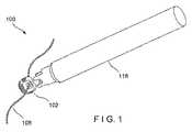
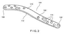
図1〜2に示すように、本発明の第1の例示的な実施形態によるシステム100は、ドライバ116と、骨プレート104に連結されて、縫合糸106を骨プレート104に接続して骨折の整復を容易にする構造を提供するように構成されている縫合糸コネクタ102と、を含む。いくつかの状況(例えば、粉砕骨折を伴う)では、骨片を安定化することが困難であり得、これにより骨折を十分に整復すること、及び/又は整復の達成後にそれを維持することが困難となり得る。縫合糸コネクタ102は、縫合糸106がプレート104に連結され得るようにすることによって骨片の更なる安定化を促進し、縫合糸106が骨片の周囲に巻かれて、互いに対する骨片の移動を防止することができる。当業者は、システム100が、任意の数の縫合糸コネクタ102と、それらが骨プレートに連結され得る任意の数の位置と、を含み得ることを理解するであろう。当業者は、縫合糸コネクタ102は、プレート104が1つ以上の骨片に固定された後であっても、骨片からプレート104を取り外すことなく、縫合糸106をプレート104に接続できるようにすることを理解するであろう。すなわち、プレート104に接続されると、プレート104が骨の一部に連結された後であっても、ユーザは貫通孔130を引き続き利用できるように、縫合糸を受け入れる貫通孔130は、プレート104の外向きの第1の表面110から離れて延在するためである。 As shown in FIGS. 1-2, a
骨プレート104は、第1の端部106から第2の端部108まで長手方向に延在し、動作位置にあるときに骨と反対方向に面する第1の表面110と、動作位置にあるときに骨に向かって面する第2の表面112と、を含む。骨プレート104は、第1の表面110から第2の表面112まで通って延在する、複数の孔114を更に含む。孔114は、縫合糸コネクタ102又はねじ付き頭部を有する係止ねじなど骨固定要素の係止頭部のいずれかを受容するように適合されている、係止孔及び可変角度の係止孔としてそれぞれ構成されてもよい。当然のことながら、プレート104はまた、非係止孔、組み合わせ孔などの係止孔又は可変角度係止孔として構成されていない任意の数の追加の孔を含んでよい。当業者は、縫合糸コネクタ102が、骨ねじの頭部を係止係合するように構成されている任意の孔又は孔の任意の部分に連結されてよいが、所望により、他の孔がプレート104に含まれてよいことを理解するであろう。孔114は、骨固定要素又は縫合糸コネクタ102の頭部を係合するための、例えば、その内側表面に沿ったねじ山(図示せず)などの係合機構を含む。当業者は、骨プレート104が、骨折を固定するために使用され得る、任意の種類の骨プレートであってよいことを理解するであろう。図2に示される骨プレート104は、骨プレート104の一例であるが、当業者は、骨プレート104が、本明細書に記載の本発明に従いつつも、様々な形態で提供され得ることを理解するであろう。例えば、骨プレートは、実質的に矩形、円形、又は任意の他の形状であってよく、任意の所望の骨又は任意の骨の任意の所望の部分に適用するように構成されてよい。骨プレート104には、1列に、並列に、互いからオフセットされて、又は骨プレート104の周りで互い違いに、又は任意の他の所望のパターンで配置された孔114が設けられてもよい。示される例は、ねじ及びピンなどの標準的な骨固定要素の頭部を係止係合するように構成されている標準的な係止孔を含む。しかしながら、当業者は、縫合糸コネクタ102又は骨固定要素と係止係合するように構成されている少なくとも1つの孔を含む限り、これは単なる例示であり、任意の所望の構成のプレートが使用されてもよいことを理解するであろう。 The
図3A〜3Bに示されるように、縫合糸コネクタ102は、骨プレート104の孔114のうちの1つにねじ方式で挿入されるように構成されている本体118を有する。一実施例では、縫合糸コネクタ102の本体118は、従来の係止ねじのねじ付き頭部と実質的に類似の寸法及び形状である。例えば、この実施形態の本体118は、実質的に丸みを帯びており、近位端120と、遠位端122と、プレート104の厚さ以下である、近位端120と遠位端122との間に延在する長さと、近位端120と遠位端122との間に延在する、丸みを帯びた側壁124(図3Aの破線によって示される)と、を有する。コネクタ102の外側表面には、少なくとも1つのプレート係合構造、例えばねじ山126が設けられている。ねじ山126は、好ましくは、取り付けられるプレート孔(例えば、従来の骨プレート係止孔又は可変角度の係止孔)のねじ山を係合する寸法である。例示的な実施形態では、縫合糸コネクタ102は、骨プレート104の孔114内で容易に係合し、嵌合するように、従来の係止ねじ頭部の寸法に対応する寸法を有する。本体118の近位部128は、係合部として構成されている。近位部128は、縫合糸106を挿入するための貫通孔130を含む。貫通孔130は、縫合糸106が容易に通過するために好適な任意の大きさであってよく、例えば、1つ以上の縫合糸コネクタ102と組み合わせると、プレート104の輪郭を最小化する、任意の形状であってよい。例えば、貫通孔130は、使用される縫合糸106の直径に等しい若しくはそれよりわずかに大きい直径を有してよい、又は貫通孔130は、本体118の軸に平行な方向の範囲で非対称であってよく、この軸に垂直な貫通孔130の寸法は、プレート104/縫合糸コネクタ102の組み合わせの輪郭を増加させずに、縫合糸の挿入を容易にするようにより大きくされ得る一方、挿入される縫合糸の厚さよりもわずかに大きい程度である。貫通孔130は、2つの凹部132に対して開口している。凹部132は、側壁から本体118の長手方向軸に向かって内側に、本体118の中央部から本体118の近位端120まで延在する。各凹部132は、縫合糸コネクタ102の長手方向軸に対して横方向に延在する、近位に面する遠位面134と、外向きの側面136と、を含む。側面136は、実質的に平坦であってよい、又は凹状に湾曲していてよい。貫通孔130は、本体118の近位部128を通って第1の凹部から第2の凹部まで延在する凹部132と連通している。凹部132及び近位本体部128を含む縫合糸コネクタ102の近位部は、当業者に理解されるように、縫合糸コネクタ102を孔114と螺合係合させて、縫合糸コネクタ102を骨プレート104に解放可能に固定するために使用される駆動ツール116の一部を係合する寸法及び形状である。例えば、凹部132は、駆動ツール116の対応する形状の部分を受容する寸法及び形状である。縫合糸コネクタ102は、例えば、ステンレス鋼又はチタンなどの好適な強度の任意の生体適合性材料などの任意の好適な材料で形成されてよい。 As shown in FIGS. 3A-3B, the
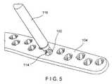
図4〜5に示されるように、縫合糸コネクタ102は、孔114に挿入されると、近位端120及び遠位端122のいずれもプレート104の第1の表面又は第2の表面を越えて延在しないように、プレート孔内で同一平面に位置する。したがって、周囲組織の刺激は最小限に抑えられる。図に見られるように、凹部132は、対応する駆動ツール116の係合部136が孔114に容易に挿入され得、プレート104へのコネクタ102の容易な挿入及びプレート104からの縫合糸コネクタ102の取り外しを容易にするように、孔114の内壁と縫合糸コネクタ102の本体118の外部との間に空隙を設ける。更に、縫合糸106はまた、当業者に理解されるように、貫通孔130に容易に挿入されてよい、又はそこから容易に取り外されてよい。 As shown in FIGS. 4-5, when the
図6〜7を参照すると、ドライバ116は、長手方向軸に沿って延在するロッド138と、ロッド138の遠位端140に連結された係合部136と、を備える。例示的な一実施形態では、ロッド138は実質的に円筒形であってよい。しかしながら、当業者であれば理解するように、ロッド138の外側表面の形状は、本発明の範囲から逸脱することなく任意の所望の形状であり得る。ロッド138及び係合部136を含むドライバ116の外側表面は、ドライバ116がその軸を中心に回転して、骨プレート104の中又は外へと縫合糸コネクタ102を駆動させるときに、周囲組織の摩耗又は刺激を最小限に抑えるために、平滑かつ連続していてよい。係合部136は、ロッド138の直系より小さい直径を有し得る。係合部136は、ベース部144から遠位に延在する2つの突起142を含む。突起142は、ドライバ116の長手方向軸から、縫合糸コネクタ本体118の近位係合部128の幅に対応する距離Dだけ横方向にオフセットされている。例示的な実施形態では、Dは近位部128の幅と等しいか、又はそれよりもわずかに大きいため、突起142は近位部128の両側で容易に摺動して係合し得る。突起142は、実質的に楕円形であってもよく、それぞれが、内側表面146、外側表面148、及び遠位面150を有する。遠位面150は、実質的に平坦であってよい、又は丸みを帯びていてよい。各突起142は、遠位面から湾曲した近位縁部154まで近位に延在する細長い切り欠き部152を含む。切り欠き部152は、内側表面146から外側表面148まで突起142の幅を延在する。湾曲した近位縁部154は、貫通孔130の曲線に一致する。具体的には、切り欠き部152は、図8に見られるように、ドライバ116が縫合糸コネクタ102と係合しているときに貫通孔130のいかなる部分も塞がないように、近位縁部154が貫通孔130の近位縁部と位置合わせされるか、又はそれよりもわずかに近位であるように構成されている。係合位置にあるとき、突起142の遠位面150は、凹部132の遠位面134に密着して位置する。内側表面146は、ドライバ116から縫合糸コネクタ102へのねじり荷重の伝達を容易にするために、近位本体部128と確実に係合するように適合されている。切り欠き部152及び貫通孔130は、ドライバ116の係合部136による係合時に縫合糸106が近位本体部129を横断するため、縫合糸106を通すための閉鎖通路を形成する。一実施形態では、ドライバ116及び縫合糸コネクタ102は、縫合糸コネクタ102の容易かつ迅速な挿入のために、例えばスナップ嵌め、摩擦嵌合など任意の好適な方法によって共に可逆的に結合されてもよい。 With reference to FIGS. 6-7, the
図9は、本実施形態による、1つ以上の縫合糸コネクタ102及びドライバ116を使用して、縫合糸106を骨プレート104に固定するための例示的な方法を示す。この例示的な方法では、骨プレート104は、例えば、プレート104を通して骨の中に1つ以上の骨固定要素(例えば、骨ねじ)を適用することなどの任意の方法を用いて骨の一部分に固定される。1つ以上の縫合糸106は、本体に挿入される前に、1つ以上の縫合糸コネクタ102の貫通孔130を通って取り付けられてよい。当業者は、縫合糸が、体内への挿入後に縫合糸コネクタ102を通され得ることを理解するであろう。しかしながら、これはより困難である可能性がある。別の実施形態では、縫合糸コネクタ102がプレート104に挿入された後、1つ以上の縫合糸106が縫合糸コネクタ102に取り付けられてよい。縫合糸106は、縫合糸コネクタ102に任意の適切な様式で取り付けられてよい。 FIG. 9 illustrates an exemplary method for securing the
例示的な実施形態では、縫合糸コネクタ102は、縫合糸コネクタ102を骨プレート104に容易に挿入するために、上述のように(例えば、摩擦嵌めによって)ドライバ116の遠位端に接続される。次いで、縫合糸コネクタ102及びドライバ116は、既に骨に固定されている骨プレート104へと切開部を通って前進する。ドライバ116の近位端は、使用中にユーザが利用できる、本体の外側に留まるハンドル及び/又はコントローラ(図示せず)を含んでもよい。ドライバ116がプレート104上の所望の位置へと前進させられると、縫合糸コネクタ102は、骨プレート104の複数の孔114のうちの選択された1つに挿入される。縫合糸コネクタ102を挿入するために利用可能な複数の位置は、プレート104、縫合糸コネクタ102、及び縫合糸106の配置時の外科医の必要性に応じた、1つ以上の縫合糸コネクタ102及び/又は縫合糸106の配置を可能にする。 In the exemplary embodiment,
縫合糸コネクタ102は、図9に示されるようにドライバ116の回転によって所望の孔114に挿入され、縫合糸コネクタ102のねじ山126がプレート孔のねじ山と係合する際に、縫合糸コネクタ102を糸通しする。したがって、プレート孔内での縫合糸コネクタ102の回転は、縫合糸コネクタ102の本体118をプレート孔に引き込み、縫合糸コネクタ102をそこに係止する。突起142の切り欠き部152は、近位係合部128の貫通孔130と位置合わせされるため、縫合糸106は、ドライバ116及び縫合糸コネクタ102の回転前、回転中、及び回転後も引き続き自由かつ容易に操作可能である。図9に示すように、凹部132のために、ドライバ116の突起142は、縫合糸コネクタ102の近位係合部128と孔114の壁との間に容易に嵌合する。 The
縫合糸コネクタ102が、孔114と同一平面であるように孔114に完全に挿入されると、ドライバ116は、縫合糸コネクタ102から分離される。当業者は、縫合糸コネクタ102が所望のように最終位置に配向されてもよく、それにより、貫通孔130の軸は、縫合糸がプレート104の周囲に巻かれる際に縫合糸が貫通することが望ましい方向に実質的に平行に延在することを理解するであろう。ドライバ116がコネクタ102に可逆的に結合される場合(例えば、スナップ嵌めによって)、ドライバ116に近位力が加えられて、ドライバを縫合糸コネクタ102から連結解除し得る。次いで、ドライバ116は、本体から取り外される。例示的な実施形態では、ユーザ(すなわち、医師)がその後、縫合糸106の位置が適切でないことに気付く場合には、縫合糸コネクタ102は取り外されて、以前に取り付けられた縫合糸コネクタ102とドライバ116を係合し、挿入とは反対方向に縫合糸コネクタ102を回転させることができる。次いで、縫合糸コネクタ102は、上記と同じ方法を使用して、異なる孔114に再配置されてよい。 When the
当業者は、本発明の趣旨又は範囲から逸脱せずに本発明の構造及び方法に様々な改変及び変更を行うことが可能であることを理解するであろう。したがって、本発明の改変及び変更が、添付の特許請求の範囲及びそれらの均等物の範囲内に含まれるものであれば、本発明はそれらを包含するものとする。 Those skilled in the art will appreciate that various modifications and changes can be made to the structure and method of the present invention without departing from the spirit or scope of the invention. Therefore, it is intended that the present invention cover modifications and variations of this invention provided they come within the scope of the appended claims and their equivalents.
〔実施の態様〕
(1) 縫合糸接続システムであって、
縫合糸コネクタであって、
骨プレートの孔に挿入されるように構成されている本体であって、前記本体は、近位端と、遠位端と、前記骨プレートの厚さに実質的に対応する、前記近位端と前記遠位端との間に延在する長さと、側壁と、を有し、前記コネクタ本体は、前記縫合糸コネクタを前記骨プレートに固定するようにねじ付きである、本体と、
前記側壁から内側に延在して近位係合部を画定する少なくとも1つの凹部と、
貫通孔であって、縫合糸を受容するように構成されており、前記近位係合部を通って延在し、前記凹部に対して開口している、貫通孔と、を含む、縫合糸コネクタと、
ドライバであって、前記ドライバの長手方向軸に沿って近位端から遠位端まで延在する細長いロッドと、前記ロッドの遠位端に連結された係合要素と、を含み、前記係合要素は、前記近位係合部を係合するように構成されている、少なくとも1つの突起を有する、ドライバと、を含む、縫合糸接続システム。
(2) 前記係合要素は2つの突起を含む、実施態様1に記載のシステム。
(3) 前記突起は切り欠き部を含む、実施態様1に記載のシステム。
(4) 前記切り欠き部は、遠位突起面から丸みを帯びた近位切り欠き縁部まで延在し、前記近位切り欠き縁部は、前記突起のいずれの部分も前記貫通孔を塞がないように、前記貫通孔の近位縁部と位置合わせされている、実施態様3に記載のシステム。
(5) 前記近位係合部は2つの凹部を含む、実施態様1に記載のシステム。Embodiment
(1) A suture connection system,
A suture connector,
A body configured to be inserted into a hole in a bone plate, wherein the body substantially corresponds to a proximal end, a distal end, and a thickness of the bone plate; A body extending between the distal end and a side wall, the connector body being threaded to secure the suture connector to the bone plate;
At least one recess extending inwardly from the side wall and defining a proximal engagement portion;
A suture comprising a through hole, the through hole being configured to receive a suture, extending through the proximal engagement portion and opening to the recess. A connector;
An elongate rod extending from a proximal end to a distal end along a longitudinal axis of the driver, and an engagement element coupled to the distal end of the rod, the engagement A suture connection system, wherein the element includes a driver having at least one protrusion configured to engage the proximal engagement portion.
2. The system of embodiment 1, wherein the engagement element includes two protrusions.
(3) The system according to embodiment 1, wherein the protrusion includes a notch.
(4) The cutout portion extends from the distal protrusion surface to a rounded proximal cutout edge portion, and the proximal cutout edge portion closes the through hole in any portion of the protrusion. 4. The system of embodiment 3, wherein the system is aligned with the proximal edge of the through-hole so that there is no.
5. The system of embodiment 1, wherein the proximal engagement portion includes two recesses.
(6) 前記突起は、前記近位係合部の側面を係合する、実施態様2に記載のシステム。
(7) 前記縫合糸コネクタは、前記縫合糸コネクタのいずれの部分も前記骨プレートの上面又は下面を越えて延在しないように、前記骨プレート孔内で同一平面に位置する寸法及び形状である、実施態様1に記載のシステム。
(8) 骨プレートアセンブリであって、
プレートであって、上面と、下面と、前記プレートを通って前記上面から前記下面まで延在する複数の孔と、を有する、プレートと、
前記プレートの前記孔のうちの1つに位置付けられた少なくとも1つの縫合糸コネクタであって、
近位端と、遠位端と、側壁と、前記側壁によって画定される第1の凹部と、前記凹部に対して開口している貫通孔と、を有する本体であって、前記第1の凹部は近位係合部を画定し、前記本体は前記プレートの前記孔に螺合するねじ山を含む、本体を含む、少なくとも1つの縫合糸コネクタと、
近位端から係合要素を含む遠位端まで延在するドライバであって、前記係合要素は、前記近位係合部を係合するように構成されている少なくとも1つの突起を有する、ドライバと、を含む、骨プレートアセンブリ。
(9) 前記係合要素は2つの突起を含む、実施態様8に記載のアセンブリ。
(10) 前記突起は切り欠き部を含む、実施態様8に記載のアセンブリ。(6) The system according to embodiment 2, wherein the protrusion engages a side surface of the proximal engagement portion.
(7) The suture connector is sized and shaped to be coplanar within the bone plate hole so that no portion of the suture connector extends beyond the upper or lower surface of the bone plate. Embodiment 4. The system of embodiment 1.
(8) a bone plate assembly,
A plate having a top surface, a bottom surface, and a plurality of holes extending through the plate from the top surface to the bottom surface;
At least one suture connector positioned in one of the holes of the plate;
A body having a proximal end, a distal end, a side wall, a first recess defined by the side wall, and a through-hole opening to the recess, the first recess At least one suture connector including a body, wherein the body includes a thread that threadably engages the hole of the plate;
A driver extending from a proximal end to a distal end including an engagement element, the engagement element having at least one protrusion configured to engage the proximal engagement portion; A bone plate assembly including a driver.
9. The assembly of embodiment 8, wherein the engagement element includes two protrusions.
(10) The assembly according to embodiment 8, wherein the protrusion includes a notch.
(11) 前記切り欠き部は、遠位突起面から丸みを帯びた近位切り欠き縁部まで延在し、前記近位切り欠き縁部は、前記突起のいずれの部分も前記貫通孔を塞がないように、前記貫通孔の近位縁部と位置合わせされている、実施態様10に記載のアセンブリ。
(12) 前記複数の孔は、係止孔又は可変角度係止孔のうちの1つである、実施態様8に記載のアセンブリ。
(13) 前記近位係合部は2つの凹部を含む、実施態様8に記載のアセンブリ。
(14) 前記突起は、前記近位係合部の側面を係合する、実施態様9に記載のアセンブリ。
(15) 前記縫合糸コネクタは、前記縫合糸コネクタのいずれの部分も前記骨プレートの上面又は下面を越えて延在しないように、前記骨プレート孔内で同一平面に位置する寸法及び形状である、実施態様8に記載のアセンブリ。(11) The notch extends from a distal protrusion surface to a rounded proximal notch edge, and the proximal notch edge closes the through hole in any part of the protrusion. Embodiment 11. The assembly of embodiment 10, wherein the assembly is aligned with the proximal edge of the through-hole such that there is no gap.
(12) The assembly according to embodiment 8, wherein the plurality of holes is one of a locking hole or a variable angle locking hole.
The assembly of claim 8, wherein the proximal engagement portion includes two recesses.
(14) The assembly according to embodiment 9, wherein the protrusion engages a side surface of the proximal engagement portion.
(15) The suture connector is sized and shaped to be coplanar within the bone plate hole so that no portion of the suture connector extends beyond the upper or lower surface of the bone plate. Embodiment 9. The assembly according to embodiment 8.
(16) 縫合糸を骨に接続するための方法であって、
骨プレートを前記骨に固定することであって、前記骨プレートは、前記プレートを通って上面から下面まで延在する複数の孔を有する、ことと、
少なくとも1つの縫合糸を縫合糸コネクタに挿入することであって、前記縫合糸コネクタは、
近位端と、遠位端と、側壁と、前記側壁によって画定される第1の凹部と、前記凹部に対して開口している貫通孔と、を有する本体であって、前記第1の凹部は近位係合部を画定し、前記本体は前記プレートの前記孔に螺合するねじ山を含む、本体を含む、ことと、
前記複数の孔のうちの1つに少なくとも1つの縫合糸コネクタを位置付けることと、
ドライバを使用して、前記縫合糸コネクタが前記孔内にねじ方式で挿入されるまで前記縫合糸コネクタを回転させることであって、前記ドライバは、細長いロッドと、前記ロッドの遠位端に連結された係合要素と、を含み、前記係合要素は、前記近位係合部を係合するように構成されている少なくとも1つの突起を含む、ことと、を含む、方法。
(17) 前記ドライバの回転が、前記ドライバから前記縫合糸コネクタにねじり荷重を伝達させて、前記縫合糸コネクタを回転させる、実施態様16に記載の方法。
(18) 前記孔から前記縫合糸コネクタを取り外すことと、
前記複数の孔のうちの第2の孔に前記縫合糸コネクタを再配置することと、
前記ドライバを使用して、前記複数の孔のうちの前記第2の孔に前記縫合糸コネクタを挿入することと、を更に含む、実施態様16に記載の方法。
(19) 前記係合要素は2つの突起を含み、前記突起は、前記近位係合部の側面を係合するように構成されている、実施態様16に記載の方法。
(20) 前記突起は切り欠き部を含み、前記切り欠き部は、遠位突起面から丸みを帯びた近位切り欠き縁部まで延在し、前記近位切り欠き縁部は、前記突起のいずれの部分も前記貫通孔を塞がないように、前記貫通孔の近位縁部と位置合わせされている、実施態様16に記載の方法。(16) A method for connecting a suture to a bone,
Securing a bone plate to the bone, the bone plate having a plurality of holes extending through the plate from an upper surface to a lower surface;
Inserting at least one suture into a suture connector, the suture connector comprising:
A body having a proximal end, a distal end, a side wall, a first recess defined by the side wall, and a through-hole opening to the recess, the first recess Defines a proximal engagement portion, and the body includes a body that includes threads that threadably engage the holes in the plate;
Positioning at least one suture connector in one of the plurality of holes;
Using a screwdriver to rotate the suture connector until the suture connector is threadedly inserted into the hole, the driver connecting an elongated rod and a distal end of the rod And wherein the engagement element includes at least one protrusion configured to engage the proximal engagement portion.
17. The method of embodiment 16, wherein rotation of the driver causes a torsional load to be transmitted from the driver to the suture connector to rotate the suture connector.
(18) removing the suture connector from the hole;
Repositioning the suture connector in a second of the plurality of holes;
The method of claim 16, further comprising inserting the suture connector into the second of the plurality of holes using the driver.
19. The method of embodiment 16, wherein the engagement element includes two protrusions, the protrusions configured to engage side surfaces of the proximal engagement portion.
(20) The protrusion includes a notch, the notch extends from a distal protrusion surface to a rounded proximal notch edge, and the proximal notch edge of the protrusion Embodiment 17. The method of embodiment 16, wherein any portion is aligned with the proximal edge of the through-hole such that it does not block the through-hole.
Claims (15)
Translated fromJapanese縫合糸コネクタであって、
骨プレートの孔に挿入されるように構成されている本体であって、前記本体は、近位端と、遠位端と、前記骨プレートの厚さに実質的に対応する、前記近位端と前記遠位端との間に延在する長さと、側壁と、を有し、前記コネクタ本体は、前記縫合糸コネクタを前記骨プレートに固定するようにねじ付きである、本体と、
前記側壁から内側に延在して近位係合部を画定する少なくとも1つの凹部と、
貫通孔であって、縫合糸を受容するように構成されており、前記近位係合部を通って延在し、前記凹部に対して開口している、貫通孔と、を含む、縫合糸コネクタと、
ドライバであって、前記ドライバの長手方向軸に沿って近位端から遠位端まで延在する細長いロッドと、前記ロッドの遠位端に連結された係合要素と、を含み、前記係合要素は、前記近位係合部を係合するように構成されている、少なくとも1つの突起を有する、ドライバと、を含む、縫合糸接続システム。A suture connection system comprising:
A suture connector,
A body configured to be inserted into a hole in a bone plate, the body having a proximal end, a distal end, and the proximal end substantially corresponding to a thickness of the bone plate A body extending between the distal end and a side wall, and the connector body is threaded to secure the suture connector to the bone plate;
At least one recess extending inwardly from the side wall and defining a proximal engagement portion;
A suture comprising a through hole, the through hole being configured to receive a suture, extending through the proximal engagement portion and opening to the recess. A connector;
An elongate rod extending from a proximal end to a distal end along a longitudinal axis of the driver, and an engagement element coupled to the distal end of the rod, the engagement A suture connection system, wherein the element includes a driver having at least one protrusion configured to engage the proximal engagement portion.
プレートであって、上面と、下面と、前記プレートを通って前記上面から前記下面まで延在する複数の孔と、を有する、プレートと、
前記プレートの前記孔のうちの1つに位置付けられた少なくとも1つの縫合糸コネクタであって、
近位端と、遠位端と、側壁と、前記側壁によって画定される第1の凹部と、前記凹部に対して開口している貫通孔と、を有する本体であって、前記第1の凹部は近位係合部を画定し、前記本体は前記プレートの前記孔に螺合するねじ山を含む、本体を含む、少なくとも1つの縫合糸コネクタと、
近位端から係合要素を含む遠位端まで延在するドライバであって、前記係合要素は、前記近位係合部を係合するように構成されている少なくとも1つの突起を有する、ドライバと、を含む、骨プレートアセンブリ。A bone plate assembly,
A plate having a top surface, a bottom surface, and a plurality of holes extending through the plate from the top surface to the bottom surface;
At least one suture connector positioned in one of the holes of the plate;
A body having a proximal end, a distal end, a side wall, a first recess defined by the side wall, and a through-hole opening to the recess, the first recess At least one suture connector including a body, wherein the body includes a thread that threadably engages the hole of the plate;
A driver extending from a proximal end to a distal end including an engagement element, the engagement element having at least one protrusion configured to engage the proximal engagement portion; A bone plate assembly including a driver.
Applications Claiming Priority (3)
| Application Number | Priority Date | Filing Date | Title |
|---|---|---|---|
| US201662412683P | 2016-10-25 | 2016-10-25 | |
| US62/412,683 | 2016-10-25 | ||
| PCT/US2017/057159WO2018080866A1 (en) | 2016-10-25 | 2017-10-18 | Suture connection system for bone plates |
Publications (1)
| Publication Number | Publication Date |
|---|---|
| JP2019533564Atrue JP2019533564A (en) | 2019-11-21 |
Family
ID=60202465
Family Applications (1)
| Application Number | Title | Priority Date | Filing Date |
|---|---|---|---|
| JP2019543168ACeasedJP2019533564A (en) | 2016-10-25 | 2017-10-18 | Bone plate suture connection system |
Country Status (7)
| Country | Link |
|---|---|
| US (1) | US11039825B2 (en) |
| EP (1) | EP3531929B1 (en) |
| JP (1) | JP2019533564A (en) |
| CN (1) | CN109906056B (en) |
| AU (1) | AU2017350662B2 (en) |
| CA (1) | CA3037987A1 (en) |
| WO (1) | WO2018080866A1 (en) |
Cited By (1)
| Publication number | Priority date | Publication date | Assignee | Title |
|---|---|---|---|---|
| JP2023513594A (en)* | 2020-02-14 | 2023-03-31 | パラゴン28・インコーポレイテッド | Bone plate hole caps, bone plate systems, and methods of using them |
Families Citing this family (2)
| Publication number | Priority date | Publication date | Assignee | Title |
|---|---|---|---|---|
| KR102654718B1 (en)* | 2018-07-31 | 2024-04-08 | 삼성디스플레이 주식회사 | Connector and display device including the connector |
| US11944361B2 (en) | 2019-08-09 | 2024-04-02 | DePuy Synthes Products, Inc. | Bone plate with structures for attachment of sutures |
Citations (9)
| Publication number | Priority date | Publication date | Assignee | Title |
|---|---|---|---|---|
| JPS63243515A (en)* | 1987-12-29 | 1988-10-11 | 足立 幸男 | Fan type bolt and fan type driver |
| JPH11216144A (en)* | 1997-11-18 | 1999-08-10 | Ethicon Inc | Tool and method for recovering suture anchor |
| JP2003523242A (en)* | 2000-02-24 | 2003-08-05 | ストライカー インスツルメンツ | Bioabsorbable joining plate, fastener, tool and method of using the same |
| JP2008194307A (en)* | 2007-02-14 | 2008-08-28 | Showa Ika Kohgyo Co Ltd | Vertebra link member and nut driver |
| JP2009500081A (en)* | 2005-06-29 | 2009-01-08 | エシコン・インコーポレイテッド | Suture anchor with improved torsion drive head |
| US20130123841A1 (en)* | 2009-09-30 | 2013-05-16 | Thomas Lyon | Apparatus and Method for a Suture Button |
| JP2013534149A (en)* | 2010-07-28 | 2013-09-02 | ジンテス ゲゼルシャフト ミット ベシュレンクテル ハフツング | System or bone fixation using biodegradable screw with radial cutout |
| JP2015525655A (en)* | 2012-08-15 | 2015-09-07 | シンセス・ゲーエムベーハーSynthes GmbH | Bone plate suture anchor |
| JP2016511061A (en)* | 2013-03-14 | 2016-04-14 | デピュイ・シンセス・プロダクツ・インコーポレイテッド | Mandible plate |
Family Cites Families (9)
| Publication number | Priority date | Publication date | Assignee | Title |
|---|---|---|---|---|
| WO1999011177A2 (en)* | 1997-09-05 | 1999-03-11 | Deslauriers Richard J | Self-retaining anchor track and method of making and using same |
| US6923824B2 (en)* | 2000-09-12 | 2005-08-02 | Axya Medical, Inc. | Apparatus and method for securing suture to bone |
| US8128658B2 (en) | 2004-11-05 | 2012-03-06 | Biomet Sports Medicine, Llc | Method and apparatus for coupling soft tissue to bone |
| US8343155B2 (en)* | 2008-05-15 | 2013-01-01 | Zimmer, Inc. | Cable button |
| WO2010062379A1 (en)* | 2008-11-25 | 2010-06-03 | Sonoma Orthopedic Products, Inc. | Bone fracture fixation screws, systems and methods of use |
| WO2011040917A1 (en)* | 2009-09-30 | 2011-04-07 | Strathmore Industries Inc. | Apparatus and method for a suture button |
| US20120158051A1 (en)* | 2010-12-17 | 2012-06-21 | Foerster Seth A | Re-tensionable knotless suture system |
| EP3061403B1 (en) | 2012-01-24 | 2018-04-18 | Synthes GmbH | Compression screw system |
| US10499968B2 (en)* | 2014-08-08 | 2019-12-10 | Stryker European Holdings I, Llc | Cable plugs for bone plates |
- 2017
- 2017-10-18JPJP2019543168Apatent/JP2019533564A/ennot_activeCeased
- 2017-10-18USUS15/787,356patent/US11039825B2/enactiveActive
- 2017-10-18WOPCT/US2017/057159patent/WO2018080866A1/ennot_activeCeased
- 2017-10-18CACA3037987Apatent/CA3037987A1/enactivePending
- 2017-10-18AUAU2017350662Apatent/AU2017350662B2/enactiveActive
- 2017-10-18CNCN201780066281.2Apatent/CN109906056B/ennot_activeExpired - Fee Related
- 2017-10-18EPEP17793789.3Apatent/EP3531929B1/enactiveActive
Patent Citations (9)
| Publication number | Priority date | Publication date | Assignee | Title |
|---|---|---|---|---|
| JPS63243515A (en)* | 1987-12-29 | 1988-10-11 | 足立 幸男 | Fan type bolt and fan type driver |
| JPH11216144A (en)* | 1997-11-18 | 1999-08-10 | Ethicon Inc | Tool and method for recovering suture anchor |
| JP2003523242A (en)* | 2000-02-24 | 2003-08-05 | ストライカー インスツルメンツ | Bioabsorbable joining plate, fastener, tool and method of using the same |
| JP2009500081A (en)* | 2005-06-29 | 2009-01-08 | エシコン・インコーポレイテッド | Suture anchor with improved torsion drive head |
| JP2008194307A (en)* | 2007-02-14 | 2008-08-28 | Showa Ika Kohgyo Co Ltd | Vertebra link member and nut driver |
| US20130123841A1 (en)* | 2009-09-30 | 2013-05-16 | Thomas Lyon | Apparatus and Method for a Suture Button |
| JP2013534149A (en)* | 2010-07-28 | 2013-09-02 | ジンテス ゲゼルシャフト ミット ベシュレンクテル ハフツング | System or bone fixation using biodegradable screw with radial cutout |
| JP2015525655A (en)* | 2012-08-15 | 2015-09-07 | シンセス・ゲーエムベーハーSynthes GmbH | Bone plate suture anchor |
| JP2016511061A (en)* | 2013-03-14 | 2016-04-14 | デピュイ・シンセス・プロダクツ・インコーポレイテッド | Mandible plate |
Cited By (2)
| Publication number | Priority date | Publication date | Assignee | Title |
|---|---|---|---|---|
| JP2023513594A (en)* | 2020-02-14 | 2023-03-31 | パラゴン28・インコーポレイテッド | Bone plate hole caps, bone plate systems, and methods of using them |
| JP7749568B2 (en) | 2020-02-14 | 2025-10-06 | パラゴン28・インコーポレイテッド | Bone plate hole caps, bone plate systems, and methods of using them |
Also Published As
| Publication number | Publication date |
|---|---|
| US20180110507A1 (en) | 2018-04-26 |
| US11039825B2 (en) | 2021-06-22 |
| EP3531929B1 (en) | 2020-12-02 |
| CN109906056B (en) | 2021-09-07 |
| AU2017350662A1 (en) | 2019-03-28 |
| AU2017350662B2 (en) | 2023-06-15 |
| CN109906056A (en) | 2019-06-18 |
| EP3531929A1 (en) | 2019-09-04 |
| CA3037987A1 (en) | 2018-05-03 |
| WO2018080866A1 (en) | 2018-05-03 |
Similar Documents
| Publication | Publication Date | Title |
|---|---|---|
| US12121274B2 (en) | Bone fracture fixation clamp | |
| US20230044584A1 (en) | Fracture fixation plate and system | |
| CA2835625C (en) | Bone fracture fixation clamp | |
| JP4945439B2 (en) | Sternum repair system | |
| EP2217164B1 (en) | Minimally invasive cerclage system | |
| JP5628675B2 (en) | Nail / plate combination | |
| CN107106213B (en) | Wire tensioner tip for wire fixation bolt | |
| JP6096514B2 (en) | Bone plate screw hole convertible to hook | |
| US9517096B2 (en) | Method and system for longitudinal closure of dissected sternums | |
| WO2000062692A2 (en) | Multi-axial bone anchor system | |
| KR20150126965A (en) | Bone repair system, kit and method | |
| US10085779B2 (en) | Intramedullary device for mid-shaft clavicle fractures | |
| JP2019533564A (en) | Bone plate suture connection system | |
| US11950816B2 (en) | Bone fracture fixation clamp | |
| JP2022089814A (en) | Systems and methods for the treatment and osteotomy of rib fractures with implants |
Legal Events
| Date | Code | Title | Description |
|---|---|---|---|
| A621 | Written request for application examination | Free format text:JAPANESE INTERMEDIATE CODE: A621 Effective date:20200923 | |
| A977 | Report on retrieval | Free format text:JAPANESE INTERMEDIATE CODE: A971007 Effective date:20210730 | |
| A131 | Notification of reasons for refusal | Free format text:JAPANESE INTERMEDIATE CODE: A131 Effective date:20210803 | |
| A521 | Request for written amendment filed | Free format text:JAPANESE INTERMEDIATE CODE: A523 Effective date:20211102 | |
| A131 | Notification of reasons for refusal | Free format text:JAPANESE INTERMEDIATE CODE: A131 Effective date:20220405 | |
| A521 | Request for written amendment filed | Free format text:JAPANESE INTERMEDIATE CODE: A523 Effective date:20220630 | |
| A01 | Written decision to grant a patent or to grant a registration (utility model) | Free format text:JAPANESE INTERMEDIATE CODE: A01 Effective date:20221025 | |
| A045 | Written measure of dismissal of application [lapsed due to lack of payment] | Free format text:JAPANESE INTERMEDIATE CODE: A045 Effective date:20230228 |