JP2019533511A - Bidirectional steel plate and diaphysis fixing system - Google Patents
Bidirectional steel plate and diaphysis fixing systemDownload PDFInfo
- Publication number
- JP2019533511A JP2019533511AJP2019521407AJP2019521407AJP2019533511AJP 2019533511 AJP2019533511 AJP 2019533511AJP 2019521407 AJP2019521407 AJP 2019521407AJP 2019521407 AJP2019521407 AJP 2019521407AJP 2019533511 AJP2019533511 AJP 2019533511A
- Authority
- JP
- Japan
- Prior art keywords
- steel plate
- locking screw
- plate body
- intramedullary nail
- diaphysis
- Prior art date
- Legal status (The legal status is an assumption and is not a legal conclusion. Google has not performed a legal analysis and makes no representation as to the accuracy of the status listed.)
- Granted
Links
Images


Classifications
- A—HUMAN NECESSITIES
- A61—MEDICAL OR VETERINARY SCIENCE; HYGIENE
- A61B—DIAGNOSIS; SURGERY; IDENTIFICATION
- A61B17/00—Surgical instruments, devices or methods
- A61B17/56—Surgical instruments or methods for treatment of bones or joints; Devices specially adapted therefor
- A61B17/58—Surgical instruments or methods for treatment of bones or joints; Devices specially adapted therefor for osteosynthesis, e.g. bone plates, screws or setting implements
- A61B17/68—Internal fixation devices, including fasteners and spinal fixators, even if a part thereof projects from the skin
- A61B17/72—Intramedullary devices, e.g. pins or nails
- A61B17/7233—Intramedullary devices, e.g. pins or nails with special means of locking the nail to the bone
- A—HUMAN NECESSITIES
- A61—MEDICAL OR VETERINARY SCIENCE; HYGIENE
- A61B—DIAGNOSIS; SURGERY; IDENTIFICATION
- A61B17/00—Surgical instruments, devices or methods
- A61B17/56—Surgical instruments or methods for treatment of bones or joints; Devices specially adapted therefor
- A61B17/58—Surgical instruments or methods for treatment of bones or joints; Devices specially adapted therefor for osteosynthesis, e.g. bone plates, screws or setting implements
- A61B17/68—Internal fixation devices, including fasteners and spinal fixators, even if a part thereof projects from the skin
- A61B17/80—Cortical plates, i.e. bone plates; Instruments for holding or positioning cortical plates, or for compressing bones attached to cortical plates
- A61B17/8004—Cortical plates, i.e. bone plates; Instruments for holding or positioning cortical plates, or for compressing bones attached to cortical plates with means for distracting or compressing the bone or bones
- A61B17/8014—Cortical plates, i.e. bone plates; Instruments for holding or positioning cortical plates, or for compressing bones attached to cortical plates with means for distracting or compressing the bone or bones the extension or compression force being caused by interaction of the plate hole and the screws
- A—HUMAN NECESSITIES
- A61—MEDICAL OR VETERINARY SCIENCE; HYGIENE
- A61B—DIAGNOSIS; SURGERY; IDENTIFICATION
- A61B17/00—Surgical instruments, devices or methods
- A61B17/56—Surgical instruments or methods for treatment of bones or joints; Devices specially adapted therefor
- A61B17/58—Surgical instruments or methods for treatment of bones or joints; Devices specially adapted therefor for osteosynthesis, e.g. bone plates, screws or setting implements
- A61B17/68—Internal fixation devices, including fasteners and spinal fixators, even if a part thereof projects from the skin
- A61B17/72—Intramedullary devices, e.g. pins or nails
- A—HUMAN NECESSITIES
- A61—MEDICAL OR VETERINARY SCIENCE; HYGIENE
- A61B—DIAGNOSIS; SURGERY; IDENTIFICATION
- A61B17/00—Surgical instruments, devices or methods
- A61B17/56—Surgical instruments or methods for treatment of bones or joints; Devices specially adapted therefor
- A61B17/58—Surgical instruments or methods for treatment of bones or joints; Devices specially adapted therefor for osteosynthesis, e.g. bone plates, screws or setting implements
- A61B17/68—Internal fixation devices, including fasteners and spinal fixators, even if a part thereof projects from the skin
- A61B17/80—Cortical plates, i.e. bone plates; Instruments for holding or positioning cortical plates, or for compressing bones attached to cortical plates
- A—HUMAN NECESSITIES
- A61—MEDICAL OR VETERINARY SCIENCE; HYGIENE
- A61B—DIAGNOSIS; SURGERY; IDENTIFICATION
- A61B17/00—Surgical instruments, devices or methods
- A61B17/56—Surgical instruments or methods for treatment of bones or joints; Devices specially adapted therefor
- A61B17/58—Surgical instruments or methods for treatment of bones or joints; Devices specially adapted therefor for osteosynthesis, e.g. bone plates, screws or setting implements
- A61B17/68—Internal fixation devices, including fasteners and spinal fixators, even if a part thereof projects from the skin
- A61B17/84—Fasteners therefor or fasteners being internal fixation devices
- A61B17/86—Pins or screws or threaded wires; nuts therefor
- A61B17/864—Pins or screws or threaded wires; nuts therefor hollow, e.g. with socket or cannulated
- A—HUMAN NECESSITIES
- A61—MEDICAL OR VETERINARY SCIENCE; HYGIENE
- A61B—DIAGNOSIS; SURGERY; IDENTIFICATION
- A61B17/00—Surgical instruments, devices or methods
- A61B2017/00526—Methods of manufacturing
- A—HUMAN NECESSITIES
- A61—MEDICAL OR VETERINARY SCIENCE; HYGIENE
- A61B—DIAGNOSIS; SURGERY; IDENTIFICATION
- A61B17/00—Surgical instruments, devices or methods
- A61B17/56—Surgical instruments or methods for treatment of bones or joints; Devices specially adapted therefor
- A61B2017/568—Surgical instruments or methods for treatment of bones or joints; Devices specially adapted therefor produced with shape and dimensions specific for an individual patient
Landscapes
- Health & Medical Sciences (AREA)
- Orthopedic Medicine & Surgery (AREA)
- Surgery (AREA)
- Life Sciences & Earth Sciences (AREA)
- Heart & Thoracic Surgery (AREA)
- Nuclear Medicine, Radiotherapy & Molecular Imaging (AREA)
- Engineering & Computer Science (AREA)
- Biomedical Technology (AREA)
- Neurology (AREA)
- Medical Informatics (AREA)
- Molecular Biology (AREA)
- Animal Behavior & Ethology (AREA)
- General Health & Medical Sciences (AREA)
- Public Health (AREA)
- Veterinary Medicine (AREA)
- Surgical Instruments (AREA)
Abstract
Translated fromJapaneseDescription
Translated fromJapanese本発明は、医療機器技術分野に関し、特に骨幹骨折後の骨癒合不全又は骨折不癒合に用いられる二方向固定鋼板及び骨幹固定システムに関する。 The present invention relates to the technical field of medical devices, and more particularly to a bi-directionally-fixed steel sheet and a diaphyseal fixation system used for bone union failure or fracture non-union after diaphyseal fracture.
従来技術において、骨折が発生した後、骨折端の安定性の度合いに応じて、基本的に安定と不安定の2つの種類に分類されてもよい。安定した骨折に対して、一般的に徒手整復、石膏、副子、ブレース、牽引制動などの外部固定方式により安定した固定を維持し、最終的に癒合させる。不安定な固定の場合、内部固定システムと外部固定システムを含む手術治療が必要であり、内部固定システムは、さらにネイルプレート固定システムと髄内ネイル固定システムに分けられる。しかし、上記の治療方式に関わらず、大規模サンプルへの追跡調査では、一部の患者に骨折不癒合又は癒合遅延が発生し、そして発生率が10%に達したことを示す。 In the prior art, after a fracture has occurred, it may be basically classified into two types, stable and unstable, according to the degree of stability of the fracture end. A stable fracture is generally maintained by an external fixation method such as manual reduction, gypsum, splint, brace, and traction braking, and finally fused. In the case of unstable fixation, surgical treatment including an internal fixation system and an external fixation system is required, and the internal fixation system is further divided into a nail plate fixation system and an intramedullary nail fixation system. Regardless of the treatment regime described above, however, follow-up on a large sample shows that some patients experienced fracture infusion or delayed fusion, and the incidence reached 10%.
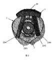
髄内ネイルシステムで固定して骨折不癒合又は癒合遅延が発生したこの一部の患者は、感染要因に加えて、骨折部位で生成した骨カルスの数により、基本的に多骨カルス又は少骨カルスの2つの種類に分類され、骨折端の安定性の度合いに応じて、安定又は不安定の2つの種類に分類されてもよい。骨折端が安定し、骨カルスが多い患者に対して、多くの場合は観察対処方式を採ることができるが、骨折端が安定し、骨カルスが少ない患者の場合、骨移植治療方式を採ることができる。不安定な骨折に対して、多骨カルス又は少骨カルにかかわらず、骨折が局所的に不安定であるため、様々な方法を採って骨折端の安定性を強化し、骨折の緩やかな癒合を促進する必要がある。しかしながら、臨床的に利用可能な内部固定方式によっては、髄内ネイルシステムで固定された後に骨折部位の骨折端に存在する欠損又は骨折で粉碎した骨折端の不安定、骨折不癒合又は骨癒合不全骨癒合不全(例えば図1における点線の円で示された骨幹1の骨折後の骨癒合不全骨癒合不全10)の内部固定などの問題を、いずれも完璧的に解决できず、即ち、現在は専門的に骨癒合不全と骨折不癒合に対して設計された固定用医療用具がなく、そのため、骨癒合不全と骨折不癒合のための内部固定用医療機器、システム又は方法を開発する必要がある。 Some patients with fixed or unfixed fractures with an intramedullary nail system may have multiple bone or calluses depending on the number of bone callus generated at the fracture site in addition to the infectious factor. It is classified into two types of callus, and may be classified into two types of stable or unstable depending on the degree of stability of the fracture end. For patients with stable fracture ends and many bone calluses, in many cases, the observation treatment method can be used. However, for patients with stable fracture ends and few bone callus, use a bone graft treatment method. Can do. For unstable fractures, regardless of whether they are multi-bone callus or small bone callus, the fracture is locally unstable, so various methods are used to enhance the stability of the fracture end and loose healing of the fracture. Need to promote. However, depending on the clinically available internal fixation method, a defect present at the fracture end of the fracture site after fixation with an intramedullary nail system, or fracture fracture instability, fracture non-union or bone union None of the problems such as internal fixation of bone union failure (for example,
本発明が従来技術における骨幹が骨折して髄内ネイルシステムで固定された後に生じる骨折端の不安定、骨折不癒合又は癒合遅延などの問題に対して提供する二方向固定鋼板構造は、骨幹の前側面に合わせる鋼板本体を使用し、そして鋼板本体にに係止ねじを貫通させるためのいくつかのガイド孔が設けられ、さらに第一の係止ねじと協力して髄内ネイルの回転及び軸方向の安定性を制御することができ、骨折端の安定した固定を実現し、骨幹の骨折端部位の位置ずれを防止し、骨折部位の正確な位置決め、整復及び癒合への支援を確保することができる。本発明は、さらに骨幹固定システムに関する。 The present invention provides a bi-directional fixed steel sheet structure for problems such as fracture end instability, fracture non-union or delayed fusion that occurs after the diaphysis in the prior art is fractured and fixed with an intramedullary nail system. A steel plate body that matches the front side is used, and several guide holes are provided in the steel plate body to allow the locking screw to pass through, and the rotation and axis of the intramedullary nail in cooperation with the first locking screw It is possible to control the stability of the direction, realize stable fixation of the fracture end, prevent misalignment of the fracture end portion of the diaphysis, and ensure support for accurate positioning, reduction and fusion of the fracture site Can do. The invention further relates to a diaphyseal fixation system.
本発明の技術的解決手段は以下のとおりである。 The technical solution of the present invention is as follows.
二方向固定鋼板は、鋼板本体を含み、前記鋼板本体が骨幹の前側からインプラントすることに用いられ、骨幹の前側面に合わせる構造を有して骨折端に固定して密着し、前記鋼板本体の骨幹の前側面に合わせる構造に、それぞれ第一の係止ねじを貫通させるための少なくとも2対のガイド孔が列設され、前記ガイド孔の角度により、貫通した各第一の係止ねじが共に髄内ネイルをクランプして髄内ネイルの回転及び軸方向の安定性への制御を実現することを特徴とする。 The two-way fixed steel plate includes a steel plate body, and the steel plate body is used for implanting from the front side of the diaphysis, and has a structure that fits the anterior side surface of the diaphysis and is fixed and closely adhered to the fracture end. At least two pairs of guide holes for penetrating the first locking screws are arranged in the structure matched to the front side surface of the diaphysis, and each of the penetrating first locking screws penetrates according to the angle of the guide holes. It is characterized in that the intramedullary nail is clamped to control the rotation and axial stability of the intramedullary nail.
前記鋼板本体の遠位端及び/又は近位端に、第二の係止ねじを貫通させるための位置決め孔が設けられ、前記位置決め孔の角度により、貫通した第二の係止ねじにより、第二の係止ねじが骨幹に緊密に接触するという位置決めを実現する。 A positioning hole for penetrating a second locking screw is provided at the distal end and / or the proximal end of the steel plate body, and the second locking screw penetrates the first locking screw depending on the angle of the positioning hole. Positioning is achieved in which the two locking screws are in intimate contact with the diaphysis.
前記鋼板本体は一体成形プロセスで製造される。 The steel plate body is manufactured by an integral forming process.
前記鋼板本体は、インプラントされる場合に、その長軸が髄内ネイルと一致し、且つ鋼板本体の長軸方向に沿って各対のガイド孔が順次設けられ、各ガイド孔が2列に配列される。 When the steel plate body is implanted, its long axis coincides with the intramedullary nail, and each pair of guide holes is sequentially provided along the long axis direction of the steel plate body, and each guide hole is arranged in two rows. Is done.
前記鋼板本体の骨幹の前側面に合わせる構造に設けられたガイド孔は2対であり、各対のガイド孔が鋼板本体の短軸に沿って設けられ、鋼板本体の長軸方向に沿って2行に分けられている。 There are two pairs of guide holes provided in a structure that matches the front side of the skeleton of the steel plate body, and each pair of guide holes is provided along the short axis of the steel plate body, and 2 guide holes are provided along the long axis direction of the steel plate body. It is divided into lines.
前記本体固定部の骨幹の前側面に合わせる構造に設けられたガイド孔は4対であり、各対のガイド孔が鋼板本体の短軸に沿って設けられ、鋼板本体の長軸方向に沿って4行に分けられている。 There are four pairs of guide holes provided in a structure that matches the front side surface of the skeleton of the main body fixing portion, and each pair of guide holes is provided along the short axis of the steel plate main body, along the long axis direction of the steel plate main body. Divided into 4 lines.
骨幹固定システムは、上記二方向固定鋼板を含み、髄内ネイル及びいくつかの第一の係止をさらに含み、前記髄内ネイルが骨折端を固定することに用いられ且つ骨幹の骨髄腔に合わせる構造を有し、各前記第一の係止ねじがそれぞれ対応するガイド孔を貫通して髄内ネイルの側面に密着して共に髄内ネイルを固定してクランプして髄内ネイルの回転及び軸方向の安定性への制御を実現することを特徴とする。 A diaphyseal fixation system includes the above-described bi-directional fixation steel plate, further including an intramedullary nail and a number of first locks, wherein the intramedullary nail is used to fix a fractured end and conforms to the bone marrow cavity of the diaphysis Each of the first locking screws has a structure, passes through the corresponding guide hole, closely contacts the side surface of the intramedullary nail, and fixes and clamps the intramedullary nail together to rotate and rotate the intramedullary nail. It is characterized by realizing control to directional stability.
前記骨幹固定システムは、二方向固定鋼板を位置決めするための、位置決め孔を貫通する第二の係止ねじをさらに含む。 The diaphysis fixing system further includes a second locking screw penetrating the positioning hole for positioning the two-way fixing steel plate.
前記第一の係止ねじと第二の係止ねじの直径範囲はいずれも2.4〜4.5mmである。 The diameter range of the first locking screw and the second locking screw is 2.4 to 4.5 mm.
前記第一の係止ねじ及び/又は第二の係止ねじは、中空係止ねじ又は中実係止ねじである。 The first locking screw and / or the second locking screw is a hollow locking screw or a solid locking screw.
本発明の技術的効果は以下のとおりである。 The technical effects of the present invention are as follows.
本発明は、鋼板本体を含み、鋼板本体が骨幹の前側からインプラントすることに用いられ且つ骨幹の前側面に合わせる構造を有して骨折端に固定して密着し、鋼板本体に、第一の係止ねじを貫通させるための少なくとも2対のガイド孔が列設され、好ましくは、鋼板本体が一体的に成形されてもよく、各対のガイド孔が応用する時にそれぞれ第一の係止ねじと協力して特定の機能を実現するように、いずれもそれぞれの特定の角度を有する二方向固定鋼板に関する。 The present invention includes a steel plate main body, the steel plate main body is used for implanting from the front side of the diaphysis and has a structure that matches the front side surface of the diaphysis, and is fixed and closely attached to the fracture end. At least two pairs of guide holes for penetrating the locking screws are arranged, preferably, the steel plate body may be integrally formed, and each pair of guide holes is applied to each of the first locking screws. Both relate to a two-way fixed steel sheet having a specific angle so as to realize a specific function in cooperation with.
本発明に係る二方向固定鋼板は、骨幹の前側面に合わせる構造を有する鋼板本体を用いて骨幹の前側からインプラントして骨幹の骨折端部位を固定し、且つ鋼板本体がさらに骨幹の骨折端部位を支持して骨折端の安定性を強化し、骨折部位の安定した整復と癒合への支援を効果的に確保することができ、特定の構造の鋼板本体が対に設置された特定の角度のガイド孔と組み合わせ、このようにして第一の係止ねじがガイド孔の方向に沿って貫通した後、共に髄内ネイルをクランプして、髄内ネイルの回転及び軸方向の安定性への制御を実現することができ、また、該ガイド孔がさらにジンバル係止孔と理解されてもよく、鋼板本体の骨幹への緊密な接触(即ち、二方向固定鋼板の骨幹への密着)、骨幹の骨折端部位に対する支持及び鋼板本体の係止を実現することができる。 The two-way fixed steel sheet according to the present invention uses a steel sheet main body having a structure matched to the anterior side surface of the diaphysis to implant the fracture end portion of the diaphysis by implanting from the front side of the diaphysis, and the steel plate main body further includes the fracture end portion of the diaphysis. Can support the stability of the fracture end, and can effectively secure stable reduction and healing of the fracture site. Combined with the guide hole, thus the first locking screw penetrates along the direction of the guide hole and then clamps the intramedullary nail together to control the rotation and axial stability of the intramedullary nail In addition, the guide hole may be further understood as a gimbal locking hole, and the steel plate main body is in close contact with the diaphysis (that is, the two-direction fixed steel plate is closely attached to the diaphysis). Support for fracture end and steel plate body It is possible to realize a locking.
そのため、本発明のユニークな構造は、骨幹の骨折端部位の回転及び軸方向の不安定性を防止し、髄内ネイルの回転を制御して支持を強化し、骨折端の安定性を高めることができる。さらに、実際に応用する時に、骨幹の前側から低侵襲でインプラントすることができ、且つ第一の係止ねじのインプラントが元々の固定妨害を受けず、二方向固定鋼板は構造がシンプルであり、体積が小さく、骨幹の前側で切開口を作ってインプラントして、ガイド孔の設定された特定の角度により、第一の係止ねじと協力する時に骨幹の骨折端部位に対する支持、回転防止及び軸方向安定化を実現し、さらに整復後の固定の信頼性を強化することができ、それによって骨折の癒合に役立つ。 Therefore, the unique structure of the present invention prevents rotation and axial instability of the fracture end portion of the diaphysis, controls the rotation of the intramedullary nail, strengthens the support, and increases the stability of the fracture end. it can. Furthermore, when actually applied, it can be implanted with minimal invasiveness from the front side of the diaphysis, and the implant of the first locking screw is not subject to the original fixation disturbance, and the two-way fixed steel plate has a simple structure, Small volume, making an incision on the anterior side of the diaphysis, implant and support the fracture end site of the diaphysis, anti-rotation and shaft when cooperating with the first locking screw according to the set angle of the guide hole Directional stabilization can be achieved, and the reliability of reduction after reduction can be enhanced, thereby helping fracture healing.
本発明に係る二方向固定鋼板は、その鋼板本体の遠位端及び/又は近位端に第二の係止ねじを貫通させるための位置決め孔がさらに設けられてもよく、このようにして第二の係止ねじが位置決め孔の方向に沿って貫通した後に、鋼板本体が骨幹に緊密に接するという位置決めを実現し、さらに整復及び固定の正確性を向上させ、骨折の治癒効果を強化することができる。 The two-way fixed steel sheet according to the present invention may further be provided with a positioning hole for allowing the second locking screw to pass through the distal end and / or the proximal end of the steel sheet body. Realize positioning that the steel plate body comes into close contact with the diaphysis after the two locking screws have penetrated along the direction of the positioning hole, and further improve the reduction and fixation accuracy and strengthen the healing effect of fractures Can do.
また、本発明に係る対に設けられたガイド孔は、その対の数に応じて鋼板本体の長軸方向に沿って順次設けられてもよいが、最終的に各ガイド孔は数行二列に配置される。具体的な配列構造が骨折部位の具体的な状況に応じて合理的に選択されてもよく、例えば、鋼板本体の長軸に沿って2行、4行、6行、8行などに分けられて、骨折端を支持し、安定化するとともに、骨折端部位に合わせて、回転及び軸方向の不安定性を防止する最適な効果を実現し、骨折の癒合を促進して骨折の癒合状態をさらに改善する。 In addition, the guide holes provided in the pairs according to the present invention may be sequentially provided along the major axis direction of the steel sheet main body according to the number of the pairs, but each guide hole finally has several rows and two columns. Placed in. The specific arrangement structure may be rationally selected according to the specific situation of the fracture site, for example, divided into 2 rows, 4 rows, 6 rows, 8 rows along the long axis of the steel plate body. To support and stabilize the fracture end, and to achieve the optimal effect of preventing rotation and axial instability according to the fracture end site, promoting fracture fusion and further improving the fracture fusion state Improve.
本発明はさらに、上記二方向固定鋼板及び第一の係止ねじを含み、髄内ネイル構造をさらに含む骨幹固定システムに関し、実際に使用する時に上記部材が組み合わせて用いられ、二方向固定鋼板の鋼板本体の長軸が髄内ネイルと一致するように維持され、髄内ネイルが骨折端部位に対する効果的な支持及び固定を実現し、二方向固定鋼板を貫通する第一の係止ねじが髄内ネイルに密着して皮質を貫通して固定され、骨幹の骨折部位の正確な位置決め及び固定、並びに回転及び軸方向の不安定性を防止することを実現する。そのため、鋼板本体が特定の角度に設けられた各ガイド孔を対応する各第一の係止ねじと組み合わせて動作することにより、二方向固定ねじ(又は二方向係止ねじ)による髄内ネイルに対する回転制御及び支持強化という効果を実現し、骨幹骨折に対する効果的な支持、安定化をさらに強化し、骨折部位の正確な位置決め及び固定を支援し、骨幹骨折の整復後の安定性を効果的に確保する。 The present invention further relates to a diaphyseal fixing system including the above-mentioned two-way fixed steel sheet and a first locking screw, and further including an intramedullary nail structure, wherein the above-mentioned members are used in combination when actually used, The long axis of the steel plate body is maintained to coincide with the intramedullary nail, the intramedullary nail provides effective support and fixation to the fracture end site, and the first locking screw that penetrates the bi-directionally fixed steel plate It is fixed in close contact with the inner nail and penetrates the cortex to achieve accurate positioning and fixation of the fracture site of the diaphysis, and prevention of rotation and axial instability. Therefore, the steel plate body operates by combining each guide hole provided at a specific angle with each corresponding first locking screw, thereby preventing the intramedullary nail by the two-way fixing screw (or two-way locking screw). Realizes the effects of rotation control and strengthening support, further strengthens effective support and stabilization for diaphyseal fractures, supports accurate positioning and fixation of fracture sites, and effectively improves stability after reduction of diaphyseal fractures Secure.
以下に図面を参照しながら本発明を説明する。 The present invention will be described below with reference to the drawings.
本発明は、鋼板本体を含み、該鋼板本体が骨幹の前側からインプラントすることに用いられ且つ骨幹の前側面に合わせる構造を有して骨折端に固定して密着し、鋼板本体の骨幹の前側面に合わせる構造に、それぞれ第一の係止ねじを貫通させるための少なくとも2対のガイド孔が列設され、該ガイド孔の角度により、貫通した各第一の係止ねじが共に髄内ネイルをクランプして髄内ネイルの回転及び軸方向の安定性への制御を実現する二方向固定鋼板に関する。 The present invention includes a steel plate main body, the steel plate main body is used for implanting from the front side of the diaphysis, and has a structure that matches the front side surface of the diaphysis, and is fixed and closely adhered to the fracture end. At least two pairs of guide holes for penetrating the first locking screws are arranged in the structure matched to the side surface, and each of the penetrating first locking screws depends on the angle of the guide holes. It is related with the two-direction fixed steel plate which controls the rotation of an intramedullary nail and axial stability.
上記鋼板本体の具体的な構造形状、及び各対のガイド孔の具体的な位置及びガイド孔の数が実際の応用状況に応じて合理的に設定されてもよく、本発明に制限されず、上記範囲を含むがそれに限定されない。例えば、鋼板本体は長方形構造として設計されてもよく、且つその内側面が骨幹の前側面に密着することができ、他の合理的な構造として設計されてもよい。また、鋼板本体は、インプラントする場合に、その長軸が髄内ネイルと一致し、且つ鋼板本体の長軸方向に沿って各対のガイド孔が順次設けられ、各ガイド孔が2列に配列し、数行二列に配置されてもよく、例えば、鋼板本体の骨幹の前側面に合わせる構造に設けられガイド孔が2対であり、各対のガイド孔が鋼板本体の短軸に沿って設けられ、鋼板本体の長軸方向に沿って2行に分けられ、又は、鋼板本体の骨幹の前側面に合わせる構造に設けられたガイド孔が4対であり、各対のガイド孔が鋼板本体の短軸に沿って設けられ、鋼板本体の長軸方向に沿って4行に分けられている。 The specific structural shape of the steel sheet main body, and the specific position of each pair of guide holes and the number of guide holes may be set rationally according to the actual application situation, not limited to the present invention, Including but not limited to the above range. For example, the steel plate body may be designed as a rectangular structure, and the inner side surface thereof may be in close contact with the anterior side surface of the diaphysis, and may be designed as another rational structure. Also, when implanting the steel plate body, the long axis coincides with the intramedullary nail, and each pair of guide holes is sequentially provided along the long axis direction of the steel plate body, and the guide holes are arranged in two rows. However, it may be arranged in several rows and two columns, for example, provided in a structure that matches the front side of the skeleton of the steel plate body, and there are two pairs of guide holes, each pair of guide holes being along the short axis of the steel plate body There are four pairs of guide holes provided in a structure that is divided into two rows along the major axis direction of the steel plate body, or is fitted to the front side of the skeleton of the steel plate body, and each pair of guide holes is a steel plate body. Provided along the minor axis of the steel plate, and is divided into four rows along the major axis direction of the steel sheet body.
具体的な配列構造は、骨折部位の具体的な状況に応じて合理的に選択されてもよく、例えば、鋼板本体の長軸に沿って2行、4行、6行、8行などに分けられて骨折端を支持し、安定化するとともに、骨折端部位に合わせて、回転及び軸方向の不安定性を防止する最適な効果を実現し、骨折の癒合を促進して骨折の癒合状態をさらに改善する。換言すれば、本発明の二方向固定鋼板は、鋼板本体の骨幹の前側面に合わせる構造に設けられたガイド孔の数に応じて二方向固定鋼板の長さを確定することができ、例えば、該二方向固定鋼板の長さが4行、6行、8行又はそれ以上であってもよい。 The specific arrangement structure may be rationally selected according to the specific situation of the fracture site, for example, divided into 2 rows, 4 rows, 6 rows, 8 rows, etc. along the long axis of the steel plate body. It supports and stabilizes the fracture end and realizes the optimal effect of preventing rotation and axial instability according to the fracture end site, promoting fracture fusion and further improving the fracture fusion state Improve. In other words, the two-way fixed steel sheet of the present invention can determine the length of the two-way fixed steel sheet according to the number of guide holes provided in the structure that matches the front side of the skeleton of the steel sheet body, for example, The length of the two-direction fixed steel plate may be 4 rows, 6 rows, 8 rows or more.
図2は本発明の二方向固定鋼板2の好ましい構造正面図である。図2に示すように、該実施例は、鋼板本体20を含み、好ましくは、鋼板本体20がステンレス鋼材料による一体成形プロセスで製造されてもよく、鋼板本体20が骨幹の前側からインプラントすることに用いられ且つ骨幹の前側面に合わせる構造を有して骨折端に固定して密着し、骨折端を支持かつ安定化し、骨折の癒合を促進し、該実施例の鋼板本体20の骨幹の前側面に合わせる構造に、第一の係止ねじを貫通させるための4対のガイド孔(例えば記号2101〜2108、即ちガイド孔2101及びガイド孔2102、ガイド孔2103及びガイド孔2104、ガイド孔2104及びガイド孔2105、ガイド孔2106及びガイド孔2106、ガイド孔2107及びガイド孔2108)が列設されることが好ましく、各ガイド孔が特定の角度に設けられ、該特定の角度により、各第一の係止ねじがガイド孔の角度に沿って係止して固定される場合、鋼板本体20が骨幹に緊密に接触すること及び貫通した各第一の係止ねじが共に髄内ネイルをクランプして髄内ネイルの回転及び軸方向の安定性を制御することを直接実現することができ、即ち、鋼板本体20の骨幹の前側面への密着、髄内ネイルの固定及び回転防止を実現し、さらに骨幹の骨折端部位の軸方向の安定化、固定的な支持及び回転防止を実現する。 FIG. 2 is a preferred structural front view of the two-way fixed
また、図2に示すように、ガイド孔2101、ガイド孔2105、ガイド孔2107及びガイド孔2103がほぼ直線に配列され、ガイド孔2102、ガイド孔2106、ガイド孔2108及びガイド孔2104がほぼ直線に配列され、即ち、各ガイド孔が4行二列に配置され、その配列形状が効果的な固定、回転防止、軸方向の不安定性防止を実現でき且つ実際の応用おいて患者への損傷が小さいことを最大限確保できれば、他の任意の設定にしてもよい。 As shown in FIG. 2, the
本発明に係る二方向固定鋼板2は、一体的に成形される鋼板本体20を含む構成としてもよく、鋼板本体20が骨幹の前側からインプラントされ且つ骨幹の前側面に合わせる構造を有し、骨折端に密着して固定する高い効果を果たすことができ、同時に第一の係止ねじと協力して長骨骨幹の骨折エリアへの軸方向における位置決め及び固定を実現し、骨折部位の位置ずれを防止することができ、骨折端の骨折不癒合又は骨癒合不全部位を良く安定化し、支持することができ、骨折の癒合の安定性を効果的に確保し、骨折部位の正確な位置決め、整復及び癒合をさらに確保して支援し、骨折の癒合を促進して骨折の癒合状態をさらに改善する。 The two-way fixed
本発明に係る二方向固定鋼板2の動作原理及び使用方法は具体的に以下のとおりである。 The operating principle and method of use of the two-way fixed
本発明に係る好ましい二方向固定鋼板2の使用状態の構造概略図は図3〜図5に示され、実際に応用する過程では、まず骨折部位、例えば骨幹1の前側面、即ち骨癒合不全の正前方において、肢体長軸に沿って皮膚、皮下、大腿四頭筋の筋腹、骨膜を切開して骨癒合不全部位を露出させ、次に鋭利な骨刀で皮質骨切り術を行い、骨折部位を十分に露出させ、低侵襲骨ドリルでそれぞれ骨粉及び皮質骨を取得し、骨粉を骨癒合不全部位に充填し、海綿骨ストリップを、切削された骨皮質の下に敷き、皮膚、筋肉の展延性を利用し、骨膜下剥離を行い、次に骨膜の下に図2に示された二方向固定鋼板2をインプラントし、鋼板本体20を骨幹の前側部位に置き、同時に鋼板本体20の内側面を骨幹の前側面に緊密に接触させることにより、良い支持、回転防止作用を果たし、骨幹骨折に対する効果的な支持及び固定を完璧的に実現し、骨折部位の正確な位置決め及び癒合を支援し、骨幹骨折の整復及び癒合の安定性を効果的に確保する。 The structural schematic diagram of the preferred state of use of the two-way fixed
図3及び図4に示すように(ここで図3は側面図であり、図4は斜視図である)、第一の係止ねじ2201と第一の係止ねじ2202がそれぞれ一定の角度で鋼板本体20に設けられた2つのガイド孔2101とガイド孔2102を貫通し、第一の係止ねじ2205と第一の係止ねじ2206がそれぞれ一定の角度で鋼板本体20に設けられた2つのガイド孔2105とガイド孔2106を貫通し、第一の係止ねじ2207と第一の係止ねじ2208がそれぞれ一定の角度で鋼板本体20に設けられた2つのガイド孔2107とガイド孔2108を貫通し、第一の係止ねじ2203と第一の係止ねじ2204がそれぞれ一定の角度で鋼板本体20に設けられた二つのガイド孔2103とガイド孔2104を貫通することにより、鋼板本体20が骨幹の前側面に密着して骨折端を固定することを実現し、同時に各ガイド孔と協力することで、貫通した各第一の係止ねじが髄内ネイル3を共にクランプして、髄内ネイル3の回転及び軸方向の安定性への制御を実現し、髄内ネイル3に対する軸方向の支持、固定、回転防止及び軸方向の安定化を実現し、且つ上記各一定の角度がいずれ各対の第一の係止ねじが髄内ネイル3を効果的にクランプでき、即ち、効果的な固定、回転防止、軸方向の不安定性防止という作用を果たし且つ実際の応用において患者への損傷が小さいことを最大限に確保できれば、いずれも実際の状況に応じて設定されてもよい。 As shown in FIGS. 3 and 4 (where FIG. 3 is a side view and FIG. 4 is a perspective view), the
また、図5に示すように(図5は図4の平面図であり、即ち、骨幹の近位端から遠位端までの図である)、上記4対即ち8つの第一の係止ねじは、それぞれほぼ2本の直線に配列され、即ち、4行二列に配置され、鋼板本体20を貫通する各第一の係止ねじがいずれも髄内ネイル3に密着しかつ皮質を貫通し(即ち、骨皮質と骨膜との間で)固定し、共に髄内ネイル3をクランプして髄内ネイル3の回転及び軸方向安定への制御を実現し、髄内ネイル3の軸方向の支持、回転防止、安定化効果を強化する。 Also, as shown in FIG. 5 (FIG. 5 is a plan view of FIG. 4, ie, a view from the proximal end to the distal end of the diaphysis), the four pairs or eight first locking screws. Are arranged in approximately two straight lines, that is, arranged in four rows and two columns, and each of the first locking screws that penetrate the
本発明に係る二方向固定鋼板2を用いてして固定した後、負圧ドレナージ管を留置し、骨膜、筋筋膜、深筋膜、皮下及び皮膚を縫合し、術後48時間以降にドレナージ管を引き抜く。さらに、骨折患者は毎日に受動的限界における膝関節活動度の練習、下肢肢体の等尺性収縮運動を行い、疼痛耐性(5キログラム荷重して爪先で着地する)の下で耐荷重運動を行う。毎月にX線で検査し、骨折の癒合状況に応じて耐荷重プロセスを決定し、患者が完全に回復するまで継続する。 After fixing using the two-way fixed
図6は本発明の二方向固定鋼板の別の好ましい構造正面図である。該実施例は、鋼板本体20の遠位端及び/又は近位端(即ち鋼板本体における上端部と下端部)に、第二の係止ねじを貫通させるための位置決め孔23がいずれも設けられ、位置決め孔の角度により、貫通した第二の係止ねじにより、鋼板本体20が骨幹に緊密に接触するという位置決めを実現し、骨幹の骨折端部位の正確な位置決め及び固定をさらに改善し、骨折の癒合効果を強化する。 FIG. 6 is another preferred structural front view of the two-way fixed steel sheet of the present invention. In this embodiment, the
本発明は、さらに二方向固定鋼板を含み、髄内ネイル及びいくつかの第一の係止ねじをさらに含み、ここで、二方向固定鋼板が図2〜図5に示す二方向固定鋼板構造を用いることができ、髄内ネイル3が骨折端を固定することに用いられ且つ骨幹の骨髄腔に合わせる構造を有し、各第一の係止ねじがそれぞれ対応するガイド孔を貫通して髄内ネイルの側面に密着して共に髄内ネイルを固定的にクランプして髄内ネイルの回転及び軸方向の安定性への制御を実現する骨幹固定システムに関する。 The present invention further includes a two-way fixed steel sheet, further including an intramedullary nail and some first locking screws, wherein the two-way fixed steel sheet has the two-way fixed steel sheet structure shown in FIGS. The
好ましくは、該骨幹固定システムはさらに二方向固定鋼板を位置決めするための、位置決め孔を貫通する第二の係止ねじを含むことができこの場合、該二方向固定鋼板が図6に示された構造を用いることができ、即ち鋼板本体の遠位端及び/又は近位端(即ち鋼板本体における上端部及び/又は下端部)に、第二の係止ねじを貫通させるための位置決め孔が設けられてもよく、位置決め孔の角度により、貫通した第二の係止ねじが鋼板本体の骨幹への緊密な接触という位置決めを実現し、骨幹の骨折端部位の正確な位置決め及び固定を実現し、骨折の癒合効果を強化する。 Preferably, the diaphyseal fixation system may further include a second locking screw through the positioning hole for positioning the two-way fixed steel sheet, in which case the two-way fixed steel sheet is shown in FIG. A structure can be used, i.e., a positioning hole is provided in the distal end and / or proximal end of the steel plate body (i.e., the upper end and / or the lower end of the steel plate body) for penetrating the second locking screw. Depending on the angle of the positioning hole, the penetrating second locking screw realizes the positioning of the steel plate body in close contact with the diaphysis, realizes accurate positioning and fixation of the fracture end portion of the diaphysis, Strengthen the healing effect of fractures.
好ましくは、二方向固定鋼板を固定するための係止ねじ(第一の係止ねじと第2の係止ねじ)の直径範囲は2.4−4.5mmであり、二方向固定鋼板を固定するための係止ねじ(第一の係止ねじと第2の係止ねじ)は、いずれも中空係止ねじ又は中実係止ねじであってもよい。 Preferably, the diameter range of the locking screws (first locking screw and second locking screw) for fixing the two-way fixed steel plate is 2.4 to 4.5 mm, and the two-way fixed steel plate is fixed. Any of the locking screws (the first locking screw and the second locking screw) may be a hollow locking screw or a solid locking screw.
図7及び図8は好ましい骨幹固定システムの使用状態の構造概略図であり、ここで、図7は側面図であり、図8は斜視図であり、上記図3又は図4に示す二方向固定鋼板2と髄内ネイル3を含み、さらに図3又は図4に示すいくつかの第一の係止ねじを用いて上記のような方式で二方向固定鋼板2を固定し、髄内ネイル3をクランプして固定し、回転を制御して支持を強化する。髄内ネイル3は、骨幹の骨髄腔に合わせる構造を有し、それぞれ各対のガイド孔を貫通したそれぞれの第一の係止ねじは、髄内ネイルの側面に密着して、髄内ネイル3の回転及び軸方向の安定性を制御し、即ち、鋼板本体20を貫通した各第一の係止ねじはいずれも髄内ネイル3に密着しかつ皮質を貫通して(即ち、骨皮質と骨膜との間で)固定し、共に髄内ネイル3をクランプして髄内ネイル3の回転及び軸方向安定への制御を実現し、各第一の係止ねじがいずれも接線にそって髄内ネイル3を抱え込むような構造を形成し、髄内ネイル3の軸方向の支持、回転防止、安定化効果をさらに強化し、さらに骨幹の骨折端部位に対する支持、回転防止及び軸方向安定化を実現する。 7 and 8 are schematic structural views of a preferred diaphyseal fixation system in use, in which FIG. 7 is a side view, FIG. 8 is a perspective view, and the two-way fixation shown in FIG. 3 or FIG. The
本発明に係る骨幹固定システムの動作原理及び使用方法は具体的に以下のとおりである。 The operation principle and method of use of the diaphyseal fixation system according to the present invention are specifically as follows.
図7及び図8に示すように、本発明に係る骨幹固定システムは、実際に使用する過程において、髄内ネイル3が骨幹の骨折端を通して骨幹の髄腔に挿入することができ、二方向固定鋼板2が一つの通常の前外側切開口を通してインプラントすることができるため、1つの開口だけで本発明に係る骨幹固定システムのインプラントを実現することができ、手術中の損傷面、損傷度及び出血量が通常より小さく、術後癒合及び回復速度が速く、図2〜5に示す二方向固定鋼板の動作原理及び使用方法が上記とおりである。 As shown in FIGS. 7 and 8, the shaft fixation system according to the present invention allows the
二方向固定鋼板2と髄内ネイル3が協力し、二方向固定鋼板2の鋼板本体20の長軸が髄内ネイル3と一致するように維持され、髄内ネイルは、骨折端部位に対する効果的な支持及び固定を実現し、二方向固定鋼板2を貫通する各第一の係止ねじがいずれも髄内ネイル3に密着し且つ皮質を貫通して固定し、即ち、鋼板本体20が、特定の角度に設けられたガイド孔により、各対応する各第一の係止ねじと協力して動作し、二方向固定ねじ(又は二方向係止ねじ)が髄内ネイル3の回転を制御して支持を強化するという効果を実現し、さらに骨幹の骨幹部位の正確な位置決め及び固定、回転防止及び軸方向の不安定性の防止を実現し、さらに骨幹の骨折に対する効果的な支持、固定を強化し、骨折部位の正確な位置決め及び固定を支援し、骨幹骨折の整復後の安定性を効果的に確保する。 The two-way fixed
なお、上記の具体的な実施形態は、当業者に本発明をより全面的に理解させるためのものであり、本発明を限定するものではない。したがって、本明細書で図面及び実施例を参照しながら本発明を詳細に説明したが、当業者であれば The specific embodiments described above are intended to allow those skilled in the art to fully understand the present invention, and are not intended to limit the present invention. Accordingly, while the present invention has been described in detail herein with reference to the drawings and examples, those skilled in the art
、本発明に対して修正又は同等置換を行うことが可能であり、本発明の精神及び範囲から逸脱しない技術的解決手段及びその改善は、いずれも本発明の特許の保護範囲内に含まれるべきである。Any technical solution and improvement that can be modified or equivalently changed without departing from the spirit and scope of the present invention should be included in the protection scope of the patent of the present invention. It is.
1−骨幹10−骨癒合不全 2−二方向固定鋼板 20−鋼板本体 2101−ガイド孔 2102−ガイド孔 2103−ガイド孔 2104−ガイド孔 2105−ガイド孔 2106−ガイド孔 2107−ガイド孔 2108−ガイド孔 2201−第一の係止ねじ 2202−第一の係止ねじ 2203−第一の係止ねじ 2204−第一の係止ねじ 2205−第一の係止ねじ 2206−第一の係止ねじ 2207−第一の係止ねじ 2208−第一の係止ねじ 23−位置決め孔 3−髄内ネイル DESCRIPTION OF SYMBOLS 1-Stem 10-Bone fusion failure 2- Bidirectional fixed steel plate 20-Steel plate main body 2101-Guide hole 2102-Guide hole 2103-Guide hole 2104-Guide hole 2105-Guide hole 2106-Guide hole 2107-Guide hole 2108-Guide hole 2201-first locking screw 2202-first locking screw 2203-first locking screw 2204-first locking screw 2205-first locking screw 2206-first locking screw 2207- 1st locking screw 2208-1st locking screw 23-positioning hole 3-intramedullary nail
Claims (10)
Translated fromJapaneseApplications Claiming Priority (1)
| Application Number | Priority Date | Filing Date | Title |
|---|---|---|---|
| PCT/CN2016/102738WO2018072181A1 (en) | 2016-10-20 | 2016-10-20 | Two-way fixing steel plate and bone fixing system |
Publications (2)
| Publication Number | Publication Date |
|---|---|
| JP2019533511Atrue JP2019533511A (en) | 2019-11-21 |
| JP6751995B2 JP6751995B2 (en) | 2020-09-09 |
Family
ID=62019057
Family Applications (1)
| Application Number | Title | Priority Date | Filing Date |
|---|---|---|---|
| JP2019521407AActiveJP6751995B2 (en) | 2016-10-20 | 2016-10-20 | Bidirectional fixing steel plate and diaphyseal fixing system |
Country Status (5)
| Country | Link |
|---|---|
| US (1) | US20220378483A1 (en) |
| EP (1) | EP3530223B1 (en) |
| JP (1) | JP6751995B2 (en) |
| ES (1) | ES2982366T3 (en) |
| WO (1) | WO2018072181A1 (en) |
Families Citing this family (3)
| Publication number | Priority date | Publication date | Assignee | Title |
|---|---|---|---|---|
| US12011199B2 (en) | 2020-10-15 | 2024-06-18 | DePuy Synthes Products, Inc. | Bone plate, bone plate system, and method of using the same |
| US11806029B2 (en) | 2021-01-06 | 2023-11-07 | DePuy Synthes Products, Inc. | Locking trocar and method of using the same |
| CN113413248A (en)* | 2021-07-27 | 2021-09-21 | 上海交通大学医学院附属第九人民医院 | Clasping type prosthesis capable of retaining intramedullary nail |
Citations (8)
| Publication number | Priority date | Publication date | Assignee | Title |
|---|---|---|---|---|
| US20060100623A1 (en)* | 2002-09-03 | 2006-05-11 | Dietmar Pennig | System for fixation of bone fractures |
| JP2007532283A (en)* | 2004-04-19 | 2007-11-15 | グローバス メディカル インコーポレイティッド | Bone fixation plate |
| JP2008086817A (en)* | 1997-02-11 | 2008-04-17 | Warsaw Orthopaedic Inc | Skeletal plating system |
| JP2010537703A (en)* | 2007-08-27 | 2010-12-09 | スシュルット サージカルス ピーブイティー.エルティーディー. | Bone plate and bone plate structure |
| JP2011511650A (en)* | 2007-09-27 | 2011-04-14 | シンセス ゲゼルシャフト ミット ベシュレンクテル ハフツング | Nail / plate combination |
| US20110190769A1 (en)* | 2008-09-16 | 2011-08-04 | Christian Haininger | Implant, in particular intramedullary pin for treating a proximal fracture of the humerus |
| JP2012524634A (en)* | 2009-04-24 | 2012-10-18 | シンセス ゲゼルシャフト ミット ベシュレンクテル ハフツング | Multiple screw |
| US20130030435A1 (en)* | 2007-10-16 | 2013-01-31 | Perez Edward A | Long bone fixation system and methods |
Family Cites Families (10)
| Publication number | Priority date | Publication date | Assignee | Title |
|---|---|---|---|---|
| US5356410A (en)* | 1991-12-13 | 1994-10-18 | Dietmar Pennig | Adjuvant for osteosynthesis in the case of pertrochanteric fracture of the neck of the femur |
| US5352228A (en)* | 1993-05-10 | 1994-10-04 | Kummer Frederick J | Apparatus and method to provide compression for a locked intramedullary nail |
| US6179839B1 (en)* | 1999-09-20 | 2001-01-30 | Kinetikos Medical Incorporated | Bone fusion apparatus and method |
| US20030069581A1 (en)* | 2001-10-04 | 2003-04-10 | Stinson David T. | Universal intramedullary nails, systems and methods of use thereof |
| US8382807B2 (en)* | 2005-07-25 | 2013-02-26 | Smith & Nephew, Inc. | Systems and methods for using polyaxial plates |
| RU2605147C2 (en)* | 2011-04-01 | 2016-12-20 | Зинтес Гмбх | System for posterior spinal fixation with plate |
| CN102949228B (en)* | 2011-08-19 | 2015-11-18 | 上海市第六人民医院 | A kind of bone fracture internal fixing device |
| US9089375B2 (en)* | 2013-10-12 | 2015-07-28 | Interfix, Llc | Combined intramedullary and extramedullary surgical aiming system and method |
| CN104771221B (en)* | 2015-04-22 | 2017-10-17 | 熊静 | A kind of intramedullary nail and its special guidance system for being used to insert target bone |
| US10687874B2 (en)* | 2015-08-27 | 2020-06-23 | Globus Medical, Inc | Proximal humeral stabilization system |
- 2016
- 2016-10-20USUS16/343,531patent/US20220378483A1/enactivePending
- 2016-10-20ESES16919581Tpatent/ES2982366T3/enactiveActive
- 2016-10-20EPEP16919581.5Apatent/EP3530223B1/enactiveActive
- 2016-10-20WOPCT/CN2016/102738patent/WO2018072181A1/ennot_activeCeased
- 2016-10-20JPJP2019521407Apatent/JP6751995B2/enactiveActive
Patent Citations (8)
| Publication number | Priority date | Publication date | Assignee | Title |
|---|---|---|---|---|
| JP2008086817A (en)* | 1997-02-11 | 2008-04-17 | Warsaw Orthopaedic Inc | Skeletal plating system |
| US20060100623A1 (en)* | 2002-09-03 | 2006-05-11 | Dietmar Pennig | System for fixation of bone fractures |
| JP2007532283A (en)* | 2004-04-19 | 2007-11-15 | グローバス メディカル インコーポレイティッド | Bone fixation plate |
| JP2010537703A (en)* | 2007-08-27 | 2010-12-09 | スシュルット サージカルス ピーブイティー.エルティーディー. | Bone plate and bone plate structure |
| JP2011511650A (en)* | 2007-09-27 | 2011-04-14 | シンセス ゲゼルシャフト ミット ベシュレンクテル ハフツング | Nail / plate combination |
| US20130030435A1 (en)* | 2007-10-16 | 2013-01-31 | Perez Edward A | Long bone fixation system and methods |
| US20110190769A1 (en)* | 2008-09-16 | 2011-08-04 | Christian Haininger | Implant, in particular intramedullary pin for treating a proximal fracture of the humerus |
| JP2012524634A (en)* | 2009-04-24 | 2012-10-18 | シンセス ゲゼルシャフト ミット ベシュレンクテル ハフツング | Multiple screw |
Also Published As
| Publication number | Publication date |
|---|---|
| EP3530223A1 (en) | 2019-08-28 |
| US20220378483A1 (en) | 2022-12-01 |
| EP3530223C0 (en) | 2024-05-22 |
| ES2982366T3 (en) | 2024-10-15 |
| WO2018072181A1 (en) | 2018-04-26 |
| EP3530223B1 (en) | 2024-05-22 |
| EP3530223A4 (en) | 2019-11-06 |
| JP6751995B2 (en) | 2020-09-09 |
Similar Documents
| Publication | Publication Date | Title |
|---|---|---|
| KR101327244B1 (en) | Method and apparatus for bone fracture fixation | |
| EP2282689B1 (en) | Apparatus for proximal humeral fracture repair | |
| US20230397918A1 (en) | System for Connecting a Connecting Device, in Particular a Distractor, to a Bone | |
| CN104487010B (en) | Elongated pin for an external modular fixation system for temporary and/or permanent fixation applications and external modular fixation system | |
| US20150250502A1 (en) | Method and Apparatus for Minimally Invasive Subcutaneous Treatment of Long Bone Fractures | |
| KR20190067202A (en) | An angled variable cephalometric nailing system for treating a femur fracture, an instrument used to place the system, including a valgus-producing osteotomy device within the scope of the present invention | |
| JP2006521163A (en) | Hybrid interlocking proximal femoral fracture fixation | |
| JP6751995B2 (en) | Bidirectional fixing steel plate and diaphyseal fixing system | |
| EP3170465A1 (en) | Device for fixing proximal humerus | |
| JP2022002747A (en) | Wing-shaped angle steel plate and bone shaft fixing system | |
| Rüedi | Intramedullary nailing with interlocking | |
| RU2584555C1 (en) | Method for lengthening femoral bone above intramedullary rod | |
| CN207400790U (en) | A kind of twin fixed guide-vane steel plate and backbone fixed system | |
| CN106344141B (en) | Two-way fixed steel plate and backbone fixing system | |
| EP1635721B1 (en) | Orthopedic clamps | |
| RU2225181C2 (en) | Fixing member for performing femur neck osteosynthesis | |
| US20150282848A1 (en) | Knee brace fixation apparatus and method for application thereof | |
| CN106236238B (en) | A kind of wing guard angle plate and backbone fixation system | |
| RU2473317C1 (en) | Method of treating fractures of proximal part of femur in conditions of osteoporosis | |
| CN100450452C (en) | Mixed interlocking type proximal femur fracture fixing device | |
| JP2022089814A (en) | Systems and methods for the treatment and osteotomy of rib fractures with implants | |
| GR1010439B (en) | Device for tension band wiring fixation of fractures, particularly of olecranon, and olecranon osteotomy and method therefor | |
| CZ2015387A3 (en) | Device for combined osteosynthesis of splintered fractures of ulna proximal section | |
| RU118545U1 (en) | DEVICE FOR OSTEOSYNTHESIS IN PREPARATORY FRACTURES | |
| Klemm | Use of the external fixator in thigh fractures |
Legal Events
| Date | Code | Title | Description |
|---|---|---|---|
| A621 | Written request for application examination | Free format text:JAPANESE INTERMEDIATE CODE: A621 Effective date:20190419 | |
| A711 | Notification of change in applicant | Free format text:JAPANESE INTERMEDIATE CODE: A711 Effective date:20200214 | |
| A521 | Request for written amendment filed | Free format text:JAPANESE INTERMEDIATE CODE: A821 Effective date:20200217 | |
| A977 | Report on retrieval | Free format text:JAPANESE INTERMEDIATE CODE: A971007 Effective date:20200316 | |
| A131 | Notification of reasons for refusal | Free format text:JAPANESE INTERMEDIATE CODE: A131 Effective date:20200324 | |
| A521 | Request for written amendment filed | Free format text:JAPANESE INTERMEDIATE CODE: A523 Effective date:20200623 | |
| TRDD | Decision of grant or rejection written | ||
| A01 | Written decision to grant a patent or to grant a registration (utility model) | Free format text:JAPANESE INTERMEDIATE CODE: A01 Effective date:20200721 | |
| A61 | First payment of annual fees (during grant procedure) | Free format text:JAPANESE INTERMEDIATE CODE: A61 Effective date:20200817 | |
| R150 | Certificate of patent or registration of utility model | Ref document number:6751995 Country of ref document:JP Free format text:JAPANESE INTERMEDIATE CODE: R150 | |
| R250 | Receipt of annual fees | Free format text:JAPANESE INTERMEDIATE CODE: R250 | |
| R250 | Receipt of annual fees | Free format text:JAPANESE INTERMEDIATE CODE: R250 | |
| R250 | Receipt of annual fees | Free format text:JAPANESE INTERMEDIATE CODE: R250 |