JP2019530603A - Self-modifying agitation method and apparatus for additive manufacturing and support removal in 3D printed materials - Google Patents
Self-modifying agitation method and apparatus for additive manufacturing and support removal in 3D printed materialsDownload PDFInfo
- Publication number
- JP2019530603A JP2019530603AJP2019540306AJP2019540306AJP2019530603AJP 2019530603 AJP2019530603 AJP 2019530603AJP 2019540306 AJP2019540306 AJP 2019540306AJP 2019540306 AJP2019540306 AJP 2019540306AJP 2019530603 AJP2019530603 AJP 2019530603A
- Authority
- JP
- Japan
- Prior art keywords
- medium
- parameters
- support material
- sensor
- chamber
- Prior art date
- Legal status (The legal status is an assumption and is not a legal conclusion. Google has not performed a legal analysis and makes no representation as to the accuracy of the status listed.)
- Pending
Links
Images


Classifications
- B—PERFORMING OPERATIONS; TRANSPORTING
- B29—WORKING OF PLASTICS; WORKING OF SUBSTANCES IN A PLASTIC STATE IN GENERAL
- B29C—SHAPING OR JOINING OF PLASTICS; SHAPING OF MATERIAL IN A PLASTIC STATE, NOT OTHERWISE PROVIDED FOR; AFTER-TREATMENT OF THE SHAPED PRODUCTS, e.g. REPAIRING
- B29C64/00—Additive manufacturing, i.e. manufacturing of three-dimensional [3D] objects by additive deposition, additive agglomeration or additive layering, e.g. by 3D printing, stereolithography or selective laser sintering
- B29C64/10—Processes of additive manufacturing
- B29C64/106—Processes of additive manufacturing using only liquids or viscous materials, e.g. depositing a continuous bead of viscous material
- B29C64/118—Processes of additive manufacturing using only liquids or viscous materials, e.g. depositing a continuous bead of viscous material using filamentary material being melted, e.g. fused deposition modelling [FDM]
- B—PERFORMING OPERATIONS; TRANSPORTING
- B29—WORKING OF PLASTICS; WORKING OF SUBSTANCES IN A PLASTIC STATE IN GENERAL
- B29C—SHAPING OR JOINING OF PLASTICS; SHAPING OF MATERIAL IN A PLASTIC STATE, NOT OTHERWISE PROVIDED FOR; AFTER-TREATMENT OF THE SHAPED PRODUCTS, e.g. REPAIRING
- B29C64/00—Additive manufacturing, i.e. manufacturing of three-dimensional [3D] objects by additive deposition, additive agglomeration or additive layering, e.g. by 3D printing, stereolithography or selective laser sintering
- B29C64/40—Structures for supporting 3D objects during manufacture and intended to be sacrificed after completion thereof
- B—PERFORMING OPERATIONS; TRANSPORTING
- B01—PHYSICAL OR CHEMICAL PROCESSES OR APPARATUS IN GENERAL
- B01F—MIXING, e.g. DISSOLVING, EMULSIFYING OR DISPERSING
- B01F31/00—Mixers with shaking, oscillating, or vibrating mechanisms
- B01F31/80—Mixing by means of high-frequency vibrations above one kHz, e.g. ultrasonic vibrations
- B01F31/89—Methodical aspects; Controlling
- B—PERFORMING OPERATIONS; TRANSPORTING
- B01—PHYSICAL OR CHEMICAL PROCESSES OR APPARATUS IN GENERAL
- B01F—MIXING, e.g. DISSOLVING, EMULSIFYING OR DISPERSING
- B01F35/00—Accessories for mixers; Auxiliary operations or auxiliary devices; Parts or details of general application
- B01F35/90—Heating or cooling systems
- B—PERFORMING OPERATIONS; TRANSPORTING
- B08—CLEANING
- B08B—CLEANING IN GENERAL; PREVENTION OF FOULING IN GENERAL
- B08B3/00—Cleaning by methods involving the use or presence of liquid or steam
- B08B3/04—Cleaning involving contact with liquid
- B08B3/10—Cleaning involving contact with liquid with additional treatment of the liquid or of the object being cleaned, e.g. by heat, by electricity or by vibration
- B08B3/102—Cleaning involving contact with liquid with additional treatment of the liquid or of the object being cleaned, e.g. by heat, by electricity or by vibration with means for agitating the liquid
- B—PERFORMING OPERATIONS; TRANSPORTING
- B08—CLEANING
- B08B—CLEANING IN GENERAL; PREVENTION OF FOULING IN GENERAL
- B08B3/00—Cleaning by methods involving the use or presence of liquid or steam
- B08B3/04—Cleaning involving contact with liquid
- B08B3/10—Cleaning involving contact with liquid with additional treatment of the liquid or of the object being cleaned, e.g. by heat, by electricity or by vibration
- B08B3/12—Cleaning involving contact with liquid with additional treatment of the liquid or of the object being cleaned, e.g. by heat, by electricity or by vibration by sonic or ultrasonic vibrations
- B—PERFORMING OPERATIONS; TRANSPORTING
- B24—GRINDING; POLISHING
- B24B—MACHINES, DEVICES, OR PROCESSES FOR GRINDING OR POLISHING; DRESSING OR CONDITIONING OF ABRADING SURFACES; FEEDING OF GRINDING, POLISHING, OR LAPPING AGENTS
- B24B49/00—Measuring or gauging equipment for controlling the feed movement of the grinding tool or work; Arrangements of indicating or measuring equipment, e.g. for indicating the start of the grinding operation
- B24B49/003—Measuring or gauging equipment for controlling the feed movement of the grinding tool or work; Arrangements of indicating or measuring equipment, e.g. for indicating the start of the grinding operation involving acoustic means
- B—PERFORMING OPERATIONS; TRANSPORTING
- B24—GRINDING; POLISHING
- B24B—MACHINES, DEVICES, OR PROCESSES FOR GRINDING OR POLISHING; DRESSING OR CONDITIONING OF ABRADING SURFACES; FEEDING OF GRINDING, POLISHING, OR LAPPING AGENTS
- B24B49/00—Measuring or gauging equipment for controlling the feed movement of the grinding tool or work; Arrangements of indicating or measuring equipment, e.g. for indicating the start of the grinding operation
- B24B49/14—Measuring or gauging equipment for controlling the feed movement of the grinding tool or work; Arrangements of indicating or measuring equipment, e.g. for indicating the start of the grinding operation taking regard of the temperature during grinding
- B—PERFORMING OPERATIONS; TRANSPORTING
- B24—GRINDING; POLISHING
- B24C—ABRASIVE OR RELATED BLASTING WITH PARTICULATE MATERIAL
- B24C11/00—Selection of abrasive materials or additives for abrasive blasts
- B24C11/005—Selection of abrasive materials or additives for abrasive blasts of additives, e.g. anti-corrosive or disinfecting agents in solid, liquid or gaseous form
- B—PERFORMING OPERATIONS; TRANSPORTING
- B24—GRINDING; POLISHING
- B24C—ABRASIVE OR RELATED BLASTING WITH PARTICULATE MATERIAL
- B24C7/00—Equipment for feeding abrasive material; Controlling the flowability, constitution, or other physical characteristics of abrasive blasts
- B24C7/0084—Equipment for feeding abrasive material; Controlling the flowability, constitution, or other physical characteristics of abrasive blasts the abrasive material being fed in a mixture of liquid and gas
- B—PERFORMING OPERATIONS; TRANSPORTING
- B29—WORKING OF PLASTICS; WORKING OF SUBSTANCES IN A PLASTIC STATE IN GENERAL
- B29C—SHAPING OR JOINING OF PLASTICS; SHAPING OF MATERIAL IN A PLASTIC STATE, NOT OTHERWISE PROVIDED FOR; AFTER-TREATMENT OF THE SHAPED PRODUCTS, e.g. REPAIRING
- B29C64/00—Additive manufacturing, i.e. manufacturing of three-dimensional [3D] objects by additive deposition, additive agglomeration or additive layering, e.g. by 3D printing, stereolithography or selective laser sintering
- B29C64/30—Auxiliary operations or equipment
- B29C64/35—Cleaning
- B—PERFORMING OPERATIONS; TRANSPORTING
- B29—WORKING OF PLASTICS; WORKING OF SUBSTANCES IN A PLASTIC STATE IN GENERAL
- B29C—SHAPING OR JOINING OF PLASTICS; SHAPING OF MATERIAL IN A PLASTIC STATE, NOT OTHERWISE PROVIDED FOR; AFTER-TREATMENT OF THE SHAPED PRODUCTS, e.g. REPAIRING
- B29C64/00—Additive manufacturing, i.e. manufacturing of three-dimensional [3D] objects by additive deposition, additive agglomeration or additive layering, e.g. by 3D printing, stereolithography or selective laser sintering
- B29C64/30—Auxiliary operations or equipment
- B29C64/379—Handling of additively manufactured objects, e.g. using robots
- B—PERFORMING OPERATIONS; TRANSPORTING
- B29—WORKING OF PLASTICS; WORKING OF SUBSTANCES IN A PLASTIC STATE IN GENERAL
- B29C—SHAPING OR JOINING OF PLASTICS; SHAPING OF MATERIAL IN A PLASTIC STATE, NOT OTHERWISE PROVIDED FOR; AFTER-TREATMENT OF THE SHAPED PRODUCTS, e.g. REPAIRING
- B29C64/00—Additive manufacturing, i.e. manufacturing of three-dimensional [3D] objects by additive deposition, additive agglomeration or additive layering, e.g. by 3D printing, stereolithography or selective laser sintering
- B29C64/30—Auxiliary operations or equipment
- B29C64/386—Data acquisition or data processing for additive manufacturing
- B29C64/393—Data acquisition or data processing for additive manufacturing for controlling or regulating additive manufacturing processes
- B—PERFORMING OPERATIONS; TRANSPORTING
- B29—WORKING OF PLASTICS; WORKING OF SUBSTANCES IN A PLASTIC STATE IN GENERAL
- B29C—SHAPING OR JOINING OF PLASTICS; SHAPING OF MATERIAL IN A PLASTIC STATE, NOT OTHERWISE PROVIDED FOR; AFTER-TREATMENT OF THE SHAPED PRODUCTS, e.g. REPAIRING
- B29C71/00—After-treatment of articles without altering their shape; Apparatus therefor
- B29C71/0009—After-treatment of articles without altering their shape; Apparatus therefor using liquids, e.g. solvents, swelling agents
- B—PERFORMING OPERATIONS; TRANSPORTING
- B33—ADDITIVE MANUFACTURING TECHNOLOGY
- B33Y—ADDITIVE MANUFACTURING, i.e. MANUFACTURING OF THREE-DIMENSIONAL [3-D] OBJECTS BY ADDITIVE DEPOSITION, ADDITIVE AGGLOMERATION OR ADDITIVE LAYERING, e.g. BY 3-D PRINTING, STEREOLITHOGRAPHY OR SELECTIVE LASER SINTERING
- B33Y30/00—Apparatus for additive manufacturing; Details thereof or accessories therefor
- B—PERFORMING OPERATIONS; TRANSPORTING
- B33—ADDITIVE MANUFACTURING TECHNOLOGY
- B33Y—ADDITIVE MANUFACTURING, i.e. MANUFACTURING OF THREE-DIMENSIONAL [3-D] OBJECTS BY ADDITIVE DEPOSITION, ADDITIVE AGGLOMERATION OR ADDITIVE LAYERING, e.g. BY 3-D PRINTING, STEREOLITHOGRAPHY OR SELECTIVE LASER SINTERING
- B33Y40/00—Auxiliary operations or equipment, e.g. for material handling
- B33Y40/20—Post-treatment, e.g. curing, coating or polishing
- B—PERFORMING OPERATIONS; TRANSPORTING
- B33—ADDITIVE MANUFACTURING TECHNOLOGY
- B33Y—ADDITIVE MANUFACTURING, i.e. MANUFACTURING OF THREE-DIMENSIONAL [3-D] OBJECTS BY ADDITIVE DEPOSITION, ADDITIVE AGGLOMERATION OR ADDITIVE LAYERING, e.g. BY 3-D PRINTING, STEREOLITHOGRAPHY OR SELECTIVE LASER SINTERING
- B33Y50/00—Data acquisition or data processing for additive manufacturing
- B33Y50/02—Data acquisition or data processing for additive manufacturing for controlling or regulating additive manufacturing processes
- G—PHYSICS
- G06—COMPUTING OR CALCULATING; COUNTING
- G06N—COMPUTING ARRANGEMENTS BASED ON SPECIFIC COMPUTATIONAL MODELS
- G06N3/00—Computing arrangements based on biological models
- G06N3/02—Neural networks
- B—PERFORMING OPERATIONS; TRANSPORTING
- B01—PHYSICAL OR CHEMICAL PROCESSES OR APPARATUS IN GENERAL
- B01F—MIXING, e.g. DISSOLVING, EMULSIFYING OR DISPERSING
- B01F35/00—Accessories for mixers; Auxiliary operations or auxiliary devices; Parts or details of general application
- B01F35/90—Heating or cooling systems
- B01F2035/99—Heating
- B—PERFORMING OPERATIONS; TRANSPORTING
- B24—GRINDING; POLISHING
- B24B—MACHINES, DEVICES, OR PROCESSES FOR GRINDING OR POLISHING; DRESSING OR CONDITIONING OF ABRADING SURFACES; FEEDING OF GRINDING, POLISHING, OR LAPPING AGENTS
- B24B31/00—Machines or devices designed for polishing or abrading surfaces on work by means of tumbling apparatus or other apparatus in which the work and/or the abrasive material is loose; Accessories therefor
- B24B31/10—Machines or devices designed for polishing or abrading surfaces on work by means of tumbling apparatus or other apparatus in which the work and/or the abrasive material is loose; Accessories therefor involving other means for tumbling of work
- Y—GENERAL TAGGING OF NEW TECHNOLOGICAL DEVELOPMENTS; GENERAL TAGGING OF CROSS-SECTIONAL TECHNOLOGIES SPANNING OVER SEVERAL SECTIONS OF THE IPC; TECHNICAL SUBJECTS COVERED BY FORMER USPC CROSS-REFERENCE ART COLLECTIONS [XRACs] AND DIGESTS
- Y02—TECHNOLOGIES OR APPLICATIONS FOR MITIGATION OR ADAPTATION AGAINST CLIMATE CHANGE
- Y02P—CLIMATE CHANGE MITIGATION TECHNOLOGIES IN THE PRODUCTION OR PROCESSING OF GOODS
- Y02P10/00—Technologies related to metal processing
- Y02P10/25—Process efficiency
Landscapes
- Engineering & Computer Science (AREA)
- Chemical & Material Sciences (AREA)
- Materials Engineering (AREA)
- Manufacturing & Machinery (AREA)
- Mechanical Engineering (AREA)
- Physics & Mathematics (AREA)
- Optics & Photonics (AREA)
- Chemical Kinetics & Catalysis (AREA)
- Theoretical Computer Science (AREA)
- Acoustics & Sound (AREA)
- Biomedical Technology (AREA)
- Computing Systems (AREA)
- Life Sciences & Earth Sciences (AREA)
- Biophysics (AREA)
- Computational Linguistics (AREA)
- Data Mining & Analysis (AREA)
- Evolutionary Computation (AREA)
- General Health & Medical Sciences (AREA)
- Molecular Biology (AREA)
- Artificial Intelligence (AREA)
- General Engineering & Computer Science (AREA)
- General Physics & Mathematics (AREA)
- Mathematical Physics (AREA)
- Software Systems (AREA)
- Health & Medical Sciences (AREA)
- Robotics (AREA)
- Cleaning By Liquid Or Steam (AREA)
Abstract
Translated fromJapaneseDescription
Translated fromJapanese本開示は概して、製造された未完成部品から支持材料を除去するための方法および装置に関し、とりわけ3Dプリントなどの積層造形技術によって製造された未完成部品に対する支持材料除去工程を最適化する方法および装置に関する。 The present disclosure relates generally to methods and apparatus for removing support material from manufactured incomplete parts, and in particular, methods for optimizing the support material removal process for incomplete parts manufactured by additive manufacturing techniques such as 3D printing and Relates to the device.
製造された未完成部品には製造に必要な部分、すなわち製造工程に必須な副産物が含まれ得るが、これらは結局のところ、完成形態の部品には不要である。本明細書でこのような部分は、「支持材料」または単に「支持体」と呼ばれる。従来の支持体除去装置では、未完成の3Dプリント部品は、不必要な支持材料を除去する工程に供せられ、これにより完成した部品が得られる。このような工程では例えば、部品は液体の満たされたタンクに投入され、そこでは支持材料を除去すべく部品の機械的アジテーション(agitation)、研磨、および/または加熱が行われる。機械的アジテーションは、(例えばポンプを介して)液体を動かすことによって、および/または超音波を用いることによって行われる。他のこのような工程では、部品は液体の噴霧による圧力にさらされ、および/または支持材料を溶かす化学溶剤によって処理され、これにより完成形態の部品が後に残る。除去工程では例えば、部品がチャンバに投入され、部品を機械的にアジテート(agitate)すべくポンプを用いてチャンバで流体を循環させ、その間、熱源からの熱が流体温度を上昇させる。こうした条件だと、支持材料は、熱的に、化学的に、機械的に、あるいはこれらの一般的方法が2つ以上組み合わさって、除去される。 The manufactured unfinished part may contain parts necessary for manufacturing, that is, by-products essential to the manufacturing process, but these are ultimately unnecessary for the finished part. Such portions are referred to herein as “support material” or simply “support”. In a conventional support removing device, an incomplete 3D printed part is subjected to a process of removing unnecessary support material, whereby a completed part is obtained. In such a process, for example, the part is placed in a liquid-filled tank where the part is mechanically agitated, ground, and / or heated to remove the support material. Mechanical agitation is performed by moving the liquid (eg, via a pump) and / or by using ultrasound. In other such processes, the part is subjected to pressure from a liquid spray and / or treated with a chemical solvent that dissolves the support material, thereby leaving behind the finished part. In the removal process, for example, a part is placed in the chamber and fluid is circulated in the chamber using a pump to mechanically agitate the part while heat from the heat source raises the fluid temperature. Under these conditions, the support material is removed thermally, chemically, mechanically, or a combination of two or more of these common methods.
従来の支持体除去方法は、支持体除去速度を最適化して、個別の製造部品に対して作業効率を最大化することはできない。支持体除去の制御に用いられる方法は複雑で、連続使用されるときでも相互に関係し合う。さらに、迅速な支持体除去の達成と部品への潜在的ダメージとの間にはしばしばトレードオフが存在する。支持体除去は通常、一度に1つか2つの除去方法の使用に制限されており、あるいは各除去方法が、管理された環境で周期的に互いに独立して評価および調整される別々の制御システムを有するシステムで用いられている。アジテーション、温度、化学薬品、流体の流動などの除去方法間の相互関係は、あるタイプの除去方法が他の除去方法を後押ししたり妨げたりするという事実にもかかわらず、概ね無視されている。 Conventional support removal methods cannot optimize support removal speed to maximize work efficiency for individual manufactured parts. The methods used to control substrate removal are complex and interrelated even when used continuously. Furthermore, there is often a trade-off between achieving rapid support removal and potential damage to parts. Support removal is usually limited to the use of one or two removal methods at a time, or each removal method has a separate control system that is evaluated and adjusted periodically and independently of each other in a controlled environment. It is used in the system that has. Interrelationships between removal methods such as agitation, temperature, chemicals, fluid flow, etc. are largely ignored, despite the fact that certain types of removal methods boost or hinder other removal methods.
さらに、製造される未完成部品は、様々なサイズ、形状、材質である。個別のサイズ、形状、材質次第で、除去方法の相性に差が出てくる。 Furthermore, the unfinished parts that are manufactured are of various sizes, shapes, and materials. Depending on the individual size, shape and material, there will be differences in the compatibility of the removal methods.
支持体除去用の既存の装置および工程は、熱、化学的処理、または研磨などの特定の除去方法の用いすぎによって、部品にダメージを与えがちである。例えば、過剰な熱は、部品のデリケートな部分を弱体化させ、最終的には部品にダメージを与え得る。また、超音波アジテーションを用いると、その中に部品が存在する媒体に相応の温度上昇を引き起こすことなく、部品を加熱してしまうこともある。その結果、部品温度の予期せぬ不必要な上昇を招き、部品のデリケートな部分にダメージを与え得る。すなわち、複数の方法が互いに作用し合うことで悪影響が生じ、これにより特定の部品に対して該方法を用いることがベストなものでなくなり得る。 Existing equipment and processes for substrate removal are prone to damage parts due to overuse of specific removal methods such as heat, chemical treatment, or polishing. For example, excessive heat can weaken the sensitive parts of the part and eventually damage the part. Also, when ultrasonic agitation is used, the part may be heated without causing a corresponding increase in temperature in the medium in which the part is present. As a result, an unexpected and unnecessary increase in the temperature of the part can be caused, and the delicate part of the part can be damaged. That is, a plurality of methods interact with each other to have an adverse effect, which may make it less optimal to use the method for a particular part.
任意の方法を用いることがベストなものでなくなれば、エネルギおよび/または時間を非効率的に用いることにつながる。例えば、超音波アジテーションの過度の使用は、過剰な加熱につながり、その間にシステムをより最適な温度へと冷却する休止時間を必要とするが、これは時間を要するため、処理効率を下げてしまう。非効率さは、部品から支持材料を完全除去するのに時間がかかりすぎる、および/または部品から材料を除去しすぎる、および/または部品の表面仕上げを台無しにする、という形で現れる。このような効率のロスは作業コストを増大させる。 If it is not best to use any method, it leads to inefficient use of energy and / or time. For example, excessive use of ultrasonic agitation leads to excessive heating during which time is required to cool the system to a more optimal temperature, which takes time and reduces processing efficiency. . Inefficiencies appear in the form of taking too much time to completely remove the support material from the part and / or removing too much material from the part and / or ruining the surface finish of the part. Such a loss of efficiency increases operating costs.
非効率さの他の例は、アジテーションの利用がベストなものでなくなることが部品にダメージを与えたり、部品の表面仕上げを台無しにすることである。アジテーションの強度が高すぎたりアジテーションがあまりに長い時間行われたりすると、支持材料が完全に除去されるだけでなく、部品の表面が過度に浸食され得る。得られた部品は容認不可能なものとなり、部品を放棄して再トライしなくてはならなくなる。 Other examples of inefficiencies are damaging the parts and ruining the surface finish of the parts that the use of agitation is not the best. If the strength of the agitation is too high or if the agitation is carried out for too long a time, not only will the support material be completely removed, but the surface of the part may be over eroded. The resulting part becomes unacceptable and must be abandoned and retried.
支持体除去用の従来の装置を用いることで生じる問題をさらに悪化させるのが、除去方法の精密な制御が不可能な点である。従来の装置は大抵の場合、温度、化学的pH、あるいはアジテーションなどの特定の方法を単に用いるか用いないかの能力をユーザに与えるもので、これは実質的に「オン/オフ切り替え」を与えるものにすぎない。例えば、アジテーションを用いて支持材料を除去する場合、循環ポンプは通常、出力100%または0%にセットされる。ユーザの選択肢を100%または0%のみに限ることで、処理を最適化することは不可能となり、部品へのダメージの危険性が増す。 The problem caused by using the conventional apparatus for removing the support is further exacerbated in that precise control of the removal method is impossible. Conventional devices often give the user the ability to simply use or not use a specific method such as temperature, chemical pH, or agitation, which effectively provides "on / off switching" It's just a thing. For example, when removing support material using agitation, the circulation pump is typically set at 100% or 0% output. By limiting the user's options to only 100% or 0%, it becomes impossible to optimize the process, and the risk of damage to the parts increases.
所与の装置での複数の支持体除去方法の同時使用は、効率を高める場合もある。ただし、複数種の支持体除去方法を管理する従来の方法は、現在のところ(a)方法をランダムに適用、(b)方法をマニュアルで適用、(c)時間ベースで順次方法を切り替える、に限られている。多くの場合、該方法は、所定の基準、確立されたプロトコル、逐次手法、時間ベース手法、オペレータの判断、またはそれらの組み合わせに基づいて作動させられ、支持材料の無差別な除去をもたらし、未完成部品からどの程度支持材料が除去されるべきかを適切に考慮することはできない。例えば、時間ベース手法のみを用いる仕上げ工場は、その装置で用いられるであろう部品や材料が多種多様であるため、これらの方法が非常に非効率的であることに気が付くであろう。例えば時間ベース手法は、実行時間が適切にセットされていなかったり、あるいは他の固定パラメータがその部品に対して攻撃的すぎると、部品全体を容易に溶かしてしまう。 The simultaneous use of multiple support removal methods on a given device may increase efficiency. However, the conventional methods for managing a plurality of types of support removal methods are currently (a) randomly applying the method, (b) manually applying the method, and (c) sequentially switching the method on a time basis. limited. In many cases, the method is operated based on predetermined criteria, established protocols, sequential methods, time-based methods, operator judgment, or a combination thereof, resulting in indiscriminate removal of support material, It cannot be adequately considered how much support material should be removed from the finished part. For example, a finishing plant that uses only a time-based approach will find that these methods are very inefficient because of the wide variety of parts and materials that will be used in the equipment. For example, the time-based approach easily melts the entire part if the execution time is not set properly or other fixed parameters are too aggressive for the part.
支持体除去装置のオペレータは、タイミングよく支持材料を除去する能力を維持しながら、そのうちのいくつかは既に述べた、非線形関係を有する処理パラメータを制御するという困難なタスクに直面する。そうした困難に加えて、異なる部品は同一の処理条件に対して異なる反応を見せるという事実もある。加熱率、超音波アジテーション、pH、部品回転速度、または他の側面を同時に最適化するのは控えめに言っても挑戦的であり、オペレータがマニュアルで行うのは非現実的である。加えて、産業上の求めがさらなる制約を課し、これが支持体除去装置およびそのオペレータの操作条件に著しい制約を課すこともあり得る。 The operator of the support removal apparatus faces the difficult task of controlling process parameters with a non-linear relationship, some of which have already been mentioned, while maintaining the ability to remove support material in a timely manner. In addition to such difficulties, there is also the fact that different parts show different responses to the same processing conditions. Simultaneously optimizing the heating rate, ultrasonic agitation, pH, part rotation speed, or other aspects is challenging to say the least and is unrealistic for the operator to do manually. In addition, industrial demands impose additional constraints, which can impose significant constraints on the operating conditions of the support removal device and its operator.
効率を高めるために、支持体除去装置を、オペレータの経験、設計データ、一般的な科学原理、および定期的テストから導き出されたルールに従わせることも考えられる。しかしこのようなルールだけでは、日常的にオペレータが遭遇する様々な作動条件のすべてにはおそらく対処できない。さらに個々の部品およびアジテーション方法の複雑さゆえに、時間ベースあるいはランダムに変化するパラメータベースのシステムだけでは最適な選択肢とはなりづらい。 In order to increase efficiency, it is also conceivable that the support removal device is subject to rules derived from operator experience, design data, general scientific principles, and periodic testing. However, such rules alone are unlikely to address all of the various operating conditions that are routinely encountered by operators. Moreover, due to the complexity of the individual parts and the agitation method, time-based or randomly changing parameter-based systems alone are not the best choice.
このように、一般的な技術または積層造形技術のいずれかで作成された部品から支持材料を自動的に除去し、かつ所定の時間間隔にわたって処理が進む間に該処理の特定のパラメータを変えることで支持材料除去工程を最適化する方法および装置が長い間待ち望まれてきた。 In this way, the support material can be automatically removed from parts made with either general or additive manufacturing techniques, and certain parameters of the process can be changed as the process proceeds over a predetermined time interval. Thus, a method and apparatus for optimizing the support material removal process has long been desired.
本発明は、製造された未完成部品から不要な材料を除去するための方法として実施可能である。このような方法は、複数の除去方法を備えた支持体除去装置の動作を最適化するための特徴を含むものとできる。このような方法では例えば、動作モデルが作成され、支持体除去装置の動作の制御に用いられる。前記モデルには支持体除去装置の作動と関連のある複数の入力パラメータが与えられ、これらの入力パラメータを用いて前記モデルが1つ以上の出力パラメータを作成する。各出力パラメータは、支持体除去装置の目標と関連している。該方法は、1つ以上の連続的な時間増分を特定し、各時間増分中に望ましい目標の1つ以上の達成を目指す1つ以上の決定を行うべく実行される。前記決定の少なくとも1つは、支持体除去装置に対応しかつ前記モデルに基づく動作の少なくとも1つの離散変数と関連している。支持体除去装置は前記決定にしたがって動作する。 The present invention can be implemented as a method for removing unwanted material from manufactured incomplete parts. Such a method may include features for optimizing the operation of the support removal apparatus with multiple removal methods. In such a method, for example, an operation model is created and used to control the operation of the support removing device. The model is provided with a plurality of input parameters related to the operation of the support removal device, and using the input parameters, the model creates one or more output parameters. Each output parameter is associated with a support removal device goal. The method is performed to identify one or more consecutive time increments and to make one or more decisions aimed at achieving one or more desired goals during each time increment. At least one of the determinations is associated with at least one discrete variable of motion corresponding to the support removal device and based on the model. The support removal device operates according to the determination.
本発明に基づくこのようなモデルでは、例えば、支持材料を有する3Dプリント部品が液体洗浄剤の入ったタンクに投入される。温度とpHを含むがこれに限定されるものではないタンク内の初期パラメータが評価され、支持材料除去のために部品に与えられるエネルギの量および種類を決定するために用いられる。支持体除去装置の初期パラメータは、オペレータの経験、静的設計データ、一般的な熱原理、および/または定期的テストに基づくものとできる。例えば、中身の詰まった物体あるいは高密度の物体は、中空の物体よりも長い初期加熱時間を必要とする。初期設定は、類似の物体での先例およびオペレータの知る熱原理に基づいて予測可能であり、該オペレータは人間またはコンピュータプログラムとすることができる。 In such a model according to the invention, for example, a 3D printed part having a support material is placed in a tank containing a liquid detergent. Initial parameters in the tank, including but not limited to temperature and pH, are evaluated and used to determine the amount and type of energy imparted to the part for support material removal. The initial parameters of the support removal device can be based on operator experience, static design data, general thermal principles, and / or periodic testing. For example, a solid or dense object requires a longer initial heating time than a hollow object. Initial settings can be predicted based on precedents on similar objects and the thermal principles known to the operator, which can be a human or a computer program.
本発明の実施例では例えば、初期予測温度設定に近い温度などの初期の処理パラメータがユーザによって選択され、タンク内での作用が時間間隔内で測定され、工程全体に対する最適値が決定される。 In an embodiment of the present invention, for example, an initial processing parameter, such as a temperature close to the initial predicted temperature setting, is selected by the user, the action in the tank is measured within a time interval, and an optimum value for the entire process is determined.
支持体除去構造を有する部品がタンクに投入されると、ポンプが用いられて、媒体(液体など)をタンク内で流動させる。媒体の流動によって、媒体内の1つ以上の部品は回転させられ、および/または、タンク内でおおまかな位置に保たれ、しばらくして部品の測定値が得られる。このような測定値には、除去された支持材料の量、または、この後除去されなくてはならない支持材料の量、が含まれる。このような測定値を得るべく、タンク内またはその近傍に設置されたセンサが用いられる。これらの測定値に応じて、除去処理パラメータが変更および/または調整され、所望の結果が得られる。このような測定を複数行った後で、支持体除去装置によって実行された特定の一連の動作パラメータが、特定の部品に対して最適化され、かつこのようなシステムが将来、より効率的な支持体除去、ただしその特定の部品だけでなく類似の他の部品に対しても、を達成するためのより正確な予測を可能とする。こうすることによって、動作パラメータの初期予測がより正確となり、その後の該方法への変更、および/または、パラメータに対する調整が小さくて済むようになる。 When a part having a support removing structure is put into a tank, a pump is used to cause a medium (liquid or the like) to flow in the tank. Due to the flow of the medium, one or more parts in the medium are rotated and / or kept in a rough position in the tank, and after some time a measurement of the part is obtained. Such measurements include the amount of support material that has been removed or the amount of support material that must subsequently be removed. In order to obtain such a measured value, a sensor installed in or near the tank is used. Depending on these measurements, the removal process parameters are changed and / or adjusted to obtain the desired result. After making multiple such measurements, the specific set of operating parameters performed by the support removal device is optimized for the specific part, and such a system will support more efficient support in the future. Allows more accurate predictions to achieve body removal, but not only for that particular part but also for other similar parts. By doing so, the initial prediction of the operating parameters is more accurate, and subsequent changes to the method and / or adjustments to the parameters can be reduced.
問題となっている部品の特徴次第では、支持材料の化学分解または熱分解などの望ましいアジテーション方法が利用可能である。ただし、望ましい方法の適用がベストなものでなくなった場合、望ましい方法の停止期間中には代わりのアジテーション方法が作動させられる。代わりのアジテーション方法は、もしもそうした代わりの方法が処理効率を高めるものであればだが、所定の時間間隔後に決定される。望ましい方法の停止期間が終わると、本発明の支持体除去システムは望ましい方法へと戻され、これは温度などの設計パラメータが再び上限に達するまで続き、その結果、望ましい方法は再び非作動となり、停止期間となる。設計パラメータが上限を超すと、その処理はベストなものでなくなる。支持体除去装置には温度センサおよび/またはpHセンサなどのセンサが備わっており、フィードバックを受け取り、様々なアジテーション方法を選択的に非作動とする。 Depending on the characteristics of the part in question, desirable agitation methods such as chemical or thermal decomposition of the support material are available. However, if the desired method is not best applied, an alternative agitation method is activated during the desired method outage. Alternative agitation methods are determined after a predetermined time interval if such alternative methods increase processing efficiency. At the end of the desired method outage period, the support removal system of the present invention is returned to the desired method, which continues until design parameters such as temperature reach the upper limit again, so that the desired method is deactivated again, It is a suspension period. If the design parameters exceed the upper limit, the processing is not the best. The support removal device is equipped with sensors such as temperature sensors and / or pH sensors to receive feedback and selectively deactivate various agitation methods.
部品へのダメージを抑えるために、各アジテーション方法を監視して、支持体除去を最大化しつつ支持材料のなくなった部品を無傷に保つ。とりわけプラスチック製3Dプリント部品については、温度が高くなりすぎるとプラスチック材料が変形するおそれがあるので、各アジテーション手段を監視して部品の温度上昇に制限を加えることが重要となる。既存の支持体除去システムと違って、本発明においては、様々なアジテーション手段が、アジテーションアルゴリズム(AGA)へのフィードバックに基づいて、順に、あるいは同時に用いられる。本発明の処理は、支持体除去を促進するために、熱、ポンピング、超音波、および化学的手段を利用する。超音波を用いたアジテーションは、支持材料のすぐ近くで、洗浄剤でキャビテーションを起こし、同時に化学反応とポンピングが相乗的に機能して支持材料の除去を促進する。 To reduce damage to the parts, each agitation method is monitored to keep the parts free of support material intact while maximizing support removal. Especially for plastic 3D printed parts, if the temperature becomes too high, the plastic material may be deformed, so it is important to monitor each agitation means and limit the temperature rise of the parts. Unlike existing support removal systems, in the present invention, various agitation means are used in sequence or simultaneously based on feedback to an agitation algorithm (AGA). The process of the present invention utilizes heat, pumping, ultrasound, and chemical means to facilitate support removal. Ultrasonic agitation causes cavitation in the immediate vicinity of the support material, and at the same time chemical reaction and pumping work synergistically to facilitate support material removal.
さらに本発明は、広義には、部品から支持材料を除去する方法を含んでおり、これは、支持材料を有する部品をチャンバ内に投入し、前記チャンバが媒体を内部に備えており、第1の時間間隔のために前記媒体の第1の組のパラメータを設定し、前記第1の時間間隔が終わるまでに、前記第1の組のパラメータを有する前記媒体が前記第1の時間間隔中に前記支持材料に与えた第1の効果を、前記チャンバ内の前記部品を監視するために動作可能に配置された第1のセンサを介して測定し、前記第1のセンサからの測定値を分析し、第2の時間間隔のために前記媒体の第2の組のパラメータを決定し、前記第2の時間間隔に前記第2の組のパラメータへと前記媒体を調整し、該方法の実行時間が尽きるまで、複数の連続する時間間隔にわたって該方法を繰り返し、該方法の前記実行時間が尽きた後に前記チャンバから前記部品を取り出すことを含む。 Furthermore, the present invention broadly includes a method for removing support material from a part, wherein the part having support material is put into a chamber, and the chamber includes a medium therein, Set a first set of parameters for the medium for a time interval of the medium, and by the time the first time interval ends, the medium having the first set of parameters is within the first time interval. A first effect imparted to the support material is measured through a first sensor operatively arranged to monitor the component in the chamber, and a measurement value from the first sensor is analyzed. Determining a second set of parameters for the medium for a second time interval, adjusting the medium to the second set of parameters for the second time interval, and executing the method Over several consecutive time intervals until The method repeatedly includes retrieving the part from the chamber after the execution time of the method is exhausted.
さらに本開示は、広義には、支持材料除去用の装置を記載しており、これは、支持材料を有する部品を受け入れるべく動作可能に配置されたチャンバと、前記チャンバ内に配置され、前記部品を包み込む媒体と、前記チャンバ内の前記媒体の温度を変化させるべく配置された温度制御ユニットと、前記チャンバ内の前記媒体をアジテートすべく配置されたアジテータと、前記チャンバ内の前記媒体を循環させるべく動作可能に配置されたポンプと、前記媒体の第1の組のパラメータを検知すべく動作可能に配置された第1のセンサと、前記第1のセンサと通信可能に接続された制御ユニットを有し、該装置の動作中に、前記第1のセンサが前記制御ユニットへと前記第1の組のパラメータを送信し、前記制御ユニットが前記第1の組のパラメータを分析して前記媒体の第2の組のパラメータを決定し、前記制御ユニットが前記第2の組のパラメータを前記温度制御ユニット、前記ポンプ、および前記アジテータへと出力する。 Furthermore, the present disclosure broadly describes an apparatus for support material removal, which includes a chamber operatively disposed to receive a component having the support material, and the component disposed within the chamber. Wrapping the medium in the chamber, a temperature control unit arranged to change the temperature of the medium in the chamber, an agitator arranged to agitate the medium in the chamber, and circulating the medium in the chamber A pump operably arranged to be operable, a first sensor operably arranged to sense a first set of parameters of the medium, and a control unit communicatively connected to the first sensor. And during operation of the apparatus, the first sensor transmits the first set of parameters to the control unit, and the control unit transmits the first set of parameters. Analyzing the data to determine the parameters of the second set of the medium, the control unit outputs to said second set of parameters the temperature control unit, the pump and the agitator.
さらに本開示は、広義には、部品から支持材料を除去する方法を記載しており、これは、チャンバ内に配置された媒体の第1の組のパラメータを決定し、第1の時間間隔中、前記第1の組のパラメータを有する前記媒体へと、支持材料を有する部品を委ね、前記第1の時間間隔が終わるまでに前記媒体の第2の組のパラメータを決定し、前記第1の時間間隔より短い第2の時間間隔中、前記第2の組のパラメータを有する前記媒体へと、前記支持材料を有する部品を委ね、該方法の実行時間が尽きるまで、複数の連続する時間間隔にわたって該方法を繰り返し、該方法の前記実行時間が尽きた後に前記媒体から前記部品を取り出すことを含む。 Furthermore, the present disclosure broadly describes a method of removing support material from a part, which determines a first set of parameters for media disposed in a chamber and during a first time interval. Entrusting a part having a support material to the medium having the first set of parameters, determining a second set of parameters of the medium by the end of the first time interval, and During a second time interval shorter than the time interval, entrust the part having the support material to the medium having the second set of parameters over a plurality of successive time intervals until the method runs out of time. Repeating the method and removing the part from the medium after the execution time of the method is exhausted.
本発明の主な目的は、支持体除去制御システムから得られた過去およびリアルタイムの動作データに基づく計算を用いる支持体除去最適化システム、方法、および装置を提供することである。 It is a primary object of the present invention to provide a support removal optimization system, method, and apparatus that uses calculations based on past and real-time operational data obtained from a support removal control system.
加えて、本発明の他の目的は、いつ、どの支持体除去アジテーションコンポーネントを選択し作動信号を送るかを最適に決定する支持体除去最適化システムおよび方法を提供することである。 In addition, another object of the present invention is to provide a support removal optimization system and method that optimally determines when to select which support removal agitation component and send an actuation signal.
さらに、本発明の他の目的は、支持体除去装置の動作を最適化する方法を提供することであり、そこでは少なくとも1つの連続的時間増分に対して1つ以上の決定がなされ、この決定の少なくとも1つが、支持体除去アジテーションコンポーネントの動作の少なくとも1つの離散変数と関連するものである。 Furthermore, another object of the present invention is to provide a method for optimizing the operation of the support removal apparatus, wherein one or more decisions are made for at least one continuous time increment, the determination At least one of which is associated with at least one discrete variable of operation of the support removal agitation component.
本発明のこれらおよび他の目的、特徴、および利点は、図面および添付の請求項を参照して以下の詳細な説明を検討することで容易に理解できるであろう。 These and other objects, features and advantages of the present invention will be readily understood upon review of the following detailed description with reference to the drawings and the appended claims.
本発明の本質および動作モードは、以下の本発明の詳細な説明ならびに添付の図面により詳しく記載されている。 The nature and mode of operation of the present invention are more fully described by the following detailed description of the invention and the accompanying drawings.
最初に、異なる図面に現れる同様の参照番号は、同一または機能的に類似した本発明の構造要素を指すことを理解されたい。本発明は開示された側面のみに限定されるものではないことも理解されたい。 Initially, like reference numerals appearing in different figures should be understood to refer to identical or functionally similar structural elements of the present invention. It should also be understood that the invention is not limited to only the disclosed aspects.
本発明はさらに、記載される特定の方法論、材料、または改良に限定されるものではなく、よって本発明は本明細書に記載されたものと変わり得ることを理解されたい。本明細書で用いられる専門用語は、特定の側面を説明することを目的とすることも理解されたい。 It is further to be understood that the invention is not limited to the particular methodologies, materials, or improvements described, and thus the invention may vary from that described herein. It is also to be understood that the terminology used herein is for the purpose of describing particular aspects.
特に定義されない限り、本明細書で用いられるあらゆる技術的および科学的用語は、本発明が関係する分野の当業者に一般的に理解されるものと同じ意味を持つ。本明細書に記載されるものと同様または等価な任意の方法、装置、または材料が、方法および装置の実施または試行に用いられ得ることを理解されたい。 Unless defined otherwise, all technical and scientific terms used herein have the same meaning as commonly understood by one of ordinary skill in the art to which this invention pertains. It should be understood that any method, apparatus, or material similar or equivalent to that described herein can be used in the practice or testing of the method and apparatus.
さらに、本明細書で用いられる「および/または」は、列挙された要素または条件が1つ以上含まれ得ること、または起こり得ることを示すために用いられる文法的な接続詞を意味するものである。例えば、第1の要素、第2の要素、および/または第3の要素を含む装置とは、以下の構造的配置:第1の要素を含む装置;第2の要素を含む装置;第3の要素を含む装置;第1の要素および第2の要素を含む装置;第1の要素および第3の要素を含む装置;第1の要素、第2の要素、および第3の要素を含む装置;第2の要素および第3の要素を含む装置、のいずれかとして解釈されることを意図したものである。 Further, as used herein, “and / or” is intended to mean a grammatical conjunction that is used to indicate that one or more of the listed elements or conditions may be included or may occur. . For example, a device that includes a first element, a second element, and / or a third element refers to the following structural arrangement: a device that includes the first element; a device that includes the second element; An apparatus including an element; an apparatus including a first element and a second element; an apparatus including a first element and a third element; an apparatus including a first element, a second element, and a third element; It is intended to be construed as either a second element and a device comprising a third element.
さらに、本明細書で用いられる「最適化(optimization)」は、何か(設計、システム、または決定)をできるだけ完璧に、機能的に、あるいは効果的にする行為、プロセス、または方法論を意味するものである。例えば最適なプロセスは、該プロセスが動作を許されたパラメータ範囲において該プロセスに可能な、最高の結果を達成し得る。さらに、本明細書で用いられる「決定(determining)」は、センサから情報を受け取り、この情報を用いてアルゴリズムを実行し、例えばそのアルゴリズムにしたがってプログラムされたコンピュータを介して出力を生じるという行為を意味するものである。 Further, “optimization” as used herein means an act, process, or methodology that makes something (design, system, or decision) as complete, functional, or effective as possible. Is. For example, an optimal process may achieve the best possible result for the process in the parameter range that the process is allowed to operate. Further, as used herein, “determining” refers to the act of receiving information from a sensor, executing an algorithm using this information, and producing output via a computer programmed according to the algorithm, for example. That means.
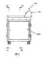
ここで図面に目を向けると、図1は、支持材料除去装置100の斜視図である。支持材料除去装置100はおおまかには、チャンバ部102、制御ユニット部104、制御入力スクリーン106、アクセスドア108A、108B、108C、および蓋110からなる。チャンバ部102内にはチャンバ120がある(図3Aに図示)。制御ユニット部104内には制御ユニット140がある。制御入力スクリーン106は、装置100によって実行されるべき特定の動作パラメータをユーザが入力可能なように配置される。 Turning now to the drawings, FIG. 1 is a perspective view of a support
図3Aおよび図3Bは、チャンバ120がチャンバ部102内に配置され、チャンバ部102内にあるものが、フィルタ122、ポンプ124、圧力センサ130、部品センサ136、冷却ユニット138、超音波変換器142(図3Bに図示)、加熱ユニット150(図4に図示)、および温度センサ152であることを示している。媒体154はチャンバ120内に動作可能に配置される。媒体154は、流体、複数の研磨用物体、またはその組み合わせとできる。ポンプ124は、チャンバ120の周囲に沿った位置でチャンバ120に固定されたパイプ126を介して、チャンバ120に接続されるものとできる。このような配置およびチャンバ120に対してパイプ126が適切に向けられることで、媒体154を動かし、チャンバ120内に渦を生じさせることが可能となる。この渦は、除去されなくてはならない支持材料162を備えた部品160の一定かつ完全なかき混ぜを可能とする。部品160を媒体と一定かつ完全にかき混ぜて、均一な支持材料除去および/または表面仕上げを保証することが望ましい。部品センサ136は、チャンバ部102内に動作可能に配置され、媒体154の部品160に対する作用を監視、これは支持材料162の監視を含む、が可能なものである。例えば部品センサ136は、特定の時間間隔中に除去された支持材料162の量を監視するために用いられる。部品センサ136は、光学センサ、赤外線センサ、熱センサ、または音響センサとすることができ、これは部品160および支持材料162の劣化の度合いを検知できる。冷却ユニット120は、好適な任意の冷却装置とすることができ、ファンを備えるものとできる。冷却ユニット120および加熱ユニット150を用いて、装置100の動作中にチャンバ120内の媒体154を冷却または加熱することができる。圧力センサ130はチャンバ136内に設けられ、ポンプ124吐出時の媒体154の圧力を検知することができる。 3A and 3B show that the
装置100の制御ユニット部104内に配置されるのは、制御入力スクリーン106、制御ユニット140、および超音波発生器132である。制御入力スクリーン106は、ワイヤ141を介して制御ユニット140に通信可能に接続されている。制御ユニット140は、ポンプ124、圧力センサ130、部品センサ136、冷却ユニット138、加熱ユニット150、超音波発生器132、および温度センサ152に通信可能に接続されている。 Disposed within the
図3Bは、概ね図2の3B−3B線に沿う支持材料除去装置100の断面図である。図3Bに示すように、超音波変換器142は、媒体154をアジテートすべく、チャンバ120に対して設置され向きを定められている。なお、媒体154を適度にアジテートすべく、他のタイプのアジテータを用いてもよい。チャンバ120の隣は越流チャンバ148(図3Bに図示)である。越流チャンバ148は、媒体154がチャンバ120から流れ出ることを許容しつつ、部品160がチャンバ120から出ないように配置されている。越流チャンバ148からは、媒体がポンプ124の取り込み側へと流れる。媒体154は、堰146を越えて越流チャンバ148へと流れ込む。媒体154が堰146を越えて流れるとき、媒体は濾過スクリーン144を通過し、これが部品160の大きな破片すなわち支持体除去工程中に外れた支持材料162を濾過して取り除く。 3B is a cross-sectional view of the support
図4はチャンバ120の斜視図である。加熱ユニット150はチャンバ120に固定されるものとできる。温度センサ152は加熱ユニット150の背後に配置され、同様にチャンバ120に固定されるものとできる。チャンバ120は、オペレータに部品をチャンバ120内に投入可能とする開口121を有する。開口121はチャンバ部102の蓋110(図1に図示)を持ち上げることでアクセス可能である。 FIG. 4 is a perspective view of the
図5は、支持材料除去方法の工程をおおまかに述べたフローチャートである。この方法では、部品160がチャンバ120内に投入される。部品160は、鋳造、鍛造、または射出成形などの従来の製造技術を用いて作成可能であるが、3Dプリントなどの積層造形技術を用いても作成可能である。部品160は通常、本明細書で支持材料162と呼ばれる不必要な部分を有しており、これは大抵の場合、鍛造で生じるバリまたは部品160の機械加工から生じるバリなどの製造工程で生じる副産物である。部品160がチャンバ120内に投入された後、ポンプ124が作動202させられ、部品160周囲の媒体154に流れを生じさせる。ポンプ124の作動202によって、部品160がチャンバ120内で回転204する。ポンプ124の作動202の結果として媒体154に生じる渦が、媒体154内で部品160を回転させ、部品160の表面被覆を実現する。部品160がチャンバ120内で回転するとき、超音波変換器142が作動206させられる。部品160からの支持材料162の除去速度を高めるべく、超音波変換器142の作動206が、部品160を取り巻く媒体154をアジテートする。媒体154のアジテーションが起きている間、部品160はチャンバ120内で回転を続け、媒体154による部品160の完全な部品被覆を保証する。該工程が不要な支持材料162を除去した後、完成した部品160がチャンバ120から除去210される。 FIG. 5 is a flowchart roughly describing the steps of the support material removing method. In this method, the
図6は、製造された未完成部品からの支持材料を繰り返す方法の実施形態を示すフローチャートである。ユーザは媒体154で満たされたチャンバ120内に部品を投入する。ステップ300で、ユーザは処理全体に関する特定のパラメータ、例えば実行時間、温度、強度レベルなどを選択する。強度レベルは、部品160からどのくらい積極的に支持材料162が除去されるかと相関関係のある因子である。強度レベルを選択することで、超音波アジテーションレベル、および/またはポンプ圧力、および/または媒体154の温度など、対応する事前選択設定が除去方法に対して自動的に選択される。ステップ300でのパラメータ入力を受けて、制御ユニット140は次に、これらのパラメータをアルゴリズムステップ301へと与える。ステップ301では、除去方法がどれくらいの速さで増加して選択されたパラメータに到達するかをアルゴリズムが判断する。超音波アジテーション、ポンプ圧力、媒体pH、および温度のすべてが部品160に影響を与えるので、各パラメータを変更したときにそのパラメータが他のものに与える影響の程度を知ることで処理を最大限予測可能とできるように、各パラメータの相互作用のバランスを取るものとできる。ステップ300の設定を用い、アルゴリズムステップ301で、アジテーションレベル、ポンプ圧力、温度などの、各除去方法に関する開始点、および各除去方法が特定の設定で実行される時間が決定される。各パラメータは、所定の時間間隔にわたって個別かつ同時に監視される。例えばステップ302では、アルゴリズムステップ301で決定された強度レベルへと温度を設定する。ステップ304では、ステップ302で設定された温度で所定の第1の時間間隔にわたって処理を実行する。そしてステップ306で温度がチェックされる。 FIG. 6 is a flowchart illustrating an embodiment of a method for repeating a support material from a manufactured unfinished part. A user places a part into a
同様に、ステップ312では、アルゴリズムステップ301のレベルへと超音波アジテーションを設定する。ステップ314では、ステップ312で設定されたアジテーションレベルで所定の第1の時間間隔にわたって処理を実行する。そしてステップ316でアジテーションレベルがチェックされる。 Similarly, in
ステップ322では、アルゴリズムステップ301のレベルへとポンプ圧力を設定する。ステップ324では、ステップ312で設定されたポンプ圧力で所定の第1の時間間隔にわたって処理を実行する。そしてステップ326でポンプ吐出圧力がチェックされる。 In
さらにステップ332では、アルゴリズムステップ301のレベルへと媒体pHを設定する。ステップ334では、ステップ332で設定された媒体pHレベルで所定の第1の時間間隔にわたって処理を実行する。そしてステップ336で媒体pHがチェックされる。 Further, in
チェック306、316、326、336後、温度、アジテーションレベル、ポンプ吐出圧力、および媒体pHの値がアルゴリズムステップ301へとフィードバックされ、温度、アジテーションレベル、ポンプ圧力、およびpHに関して第2の組のパラメータが決定される。第2の組のパラメータを用い、所定の第2の時間間隔にわたって再び処理が実行される。ちなみに第2の時間間隔は、第1の時間間隔よりも短いものとできる。該処理は、処理終了までに複数の時間間隔にわたって実行可能である。このように処理は繰り返され、特定の時間枠内で支持体除去処理を最適化するように機能する。この処理は全体的には、処理が繰り返される毎にパラメータを望ましいレベルへと近づける。好ましい実施形態では、アルゴリズムステップ301は、同じ装置および方法を用いて他の部品に対して行われた複数の処理から作り出されたパラメータデーターベースを利用する。これらのパラメータの分析は、特定の部品処理に関して処理の最適化を可能とする。 After
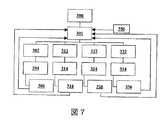
図7は、支持材料除去方法の他の実施形態を示すフローチャートである。この支持材料除去方法の第2の実施形態は、図6に示された第1の実施形態の方法と類似するが、追加のステップ350が含まれる。ステップ350では、支持材料が除去されている間に装置内の部品をスキャンする。このようなスキャニングは、(a):部品から除去された支持材料の量、(b):部品に残る支持材料の量、または(c):(a)と(b)の両方、を測定するために用いられる。この情報すなわち測定値は、データとしてアルゴリズムステップ301へと送られ、処理のパラメータレベルを決定するために用いられる。ステップ350の測定値を評価することで、1つ以上の先行する時間間隔中でどの程度処理が効果的であったかに基づいて、処理を適応させることが可能となる。さらに、これも当然のことだが、ステップ350は、部品上の支持材料のリアルタイム測定であってもよいし、あるいは部品のコンピュータ支援設計(CAD)モデルの評価であってもよい。部品のスキャニング350によって得られた情報をステップ301のアルゴリズムに用いることで、処理のために選択されるパラメータをより効率的に決定することが可能となる。 FIG. 7 is a flowchart showing another embodiment of the support material removing method. This second embodiment of the support material removal method is similar to the method of the first embodiment shown in FIG. 6 but includes an
以上の記載においては代表的な実施形態を説明した。よって本明細書と図面は、限定のためというより解説のためのものとして理解されるべきである。 In the above description, typical embodiments have been described. Accordingly, the specification and drawings are to be understood as illustrative rather than restrictive.
当然ながら、以上に開示した本発明の様々な側面、および他の特徴および機能、またはその代案を望むがままに組み合わせて、他の多くの異なるシステムまたは用途とすることが可能である。現時点では予想も予期もされていない様々な代案、変形、変異、または改良が今後当業者によってなされる可能性もあるが、それらもまた以下の請求項によって包含されるものである。 Of course, the various aspects of the invention disclosed above, and other features and functions, or alternatives thereof, can be combined as desired in many other different systems or applications. Various alternatives, modifications, variations, or improvements that are not currently anticipated or anticipated may be made by those skilled in the art, which are also encompassed by the following claims.
100 支持材料除去装置
102 チャンバ部
104 制御ユニット部
106 制御入力スクリーン
108A アクセスドア
108B アクセスドア
108C アクセスドア
110 蓋
120 チャンバ
121 開口
122 フィルタ
124 ポンプ
126 パイプ
130 圧力センサ
136 センサ
138 冷却ユニット
142 超音波変換器
144 濾過スクリーン
146 堰
148 越流チャンバ
150 加熱ユニット
152 温度センサ
154 媒体
160 部品
162 支持材料
200 投入ステップ
202 作動ステップ
204 回転ステップ
206 アジテーションステップ
210 除去ステップ
300 初期パラメータエントリステップ
301 アルゴリズムステップ
302 温度設定ステップ
304 処理実行ステップ
306 温度確認ステップ
312 アジテーションレベル設定ステップ
314 処理実行ステップ
316 アジテーションレベル確認ステップ
322 ポンプ圧力設定ステップ
324 処理実行ステップ
326 ポンプ圧力確認ステップ
332 pH/液体レベル設定ステップ
334 処理実行ステップ
336 pH/液体レベル確認ステップ
350 スキャニングステップDESCRIPTION OF
関連出願の相互参照
本願は、2016年10月10日に出願された米国仮特許出願番号第62/406187号の優先権を主張するものであって、この出願は全体が本明細書に組み込まれるものであり、図8の後に続く。CROSS REFERENCE TO RELATED APPLICATIONS This application claims priority to US Provisional Patent Application No. 62/406187, filed October 10, 2016, which is incorporated herein in its entirety. Which follows FIG.
米国仮特許出願番号第62/406187号は本願の一部であり、以下の頁に記載される。 US Provisional Patent Application No. 62/406187 is part of this application and is described on the following pages.
発明の名称
3Dプリント部品における回転支持構造物除去のための自己修正方法Patent application title: Self-correcting method for removing rotational support structures in 3D printed parts
技術分野
本開示は概して、3Dプリント部品用の支持体除去装置およびシステムの動作に関し、とりわけ人工知能技術を用いて3Dプリント部品用の支持体除去装置の動作を最適化する方法および装置に関する。TECHNICAL FIELD The present disclosure relates generally to the operation of a support removal apparatus and system for 3D printed parts, and more particularly to a method and apparatus for optimizing the operation of a support removal apparatus for 3D printed parts using artificial intelligence techniques.
背景技術
従来の支持体除去ユニットでは、3Dプリント部品が機械的アジテーションおよび加熱のために液体の満たされたタンクに投入され、液体の噴霧による圧力にさらされ、あるいは支持材料を溶かすための化学溶剤によって処理され、完成部品のみを後に残す。タンクへはポンプが接続され、液体の流動、吸い込み、および圧力を生じさせ、これにより部品を回転、さもなくば機械的にアジテートし、その間に熱源からの熱が部品を取り巻く流体の温度を上昇させ、支持材料を除去する。支持材料は溶解、さもなくば除去され、部品のみを後に残す。部品から支持体を除去すべく、高圧の液体噴霧もまた利用可能である。従来の装置では、熱、流体の動き、超音波、および化学溶解を含む装置パラメータを変えることで支持体除去が行われてきた。In a conventional support removal unit, a 3D printed part is put into a liquid-filled tank for mechanical agitation and heating, exposed to the pressure of a liquid spray, or a chemical solvent for dissolving the support material Only the finished part is left behind. A pump is connected to the tank to create fluid flow, suction, and pressure, which causes the part to rotate or otherwise mechanically agitate while the heat from the heat source raises the temperature of the fluid surrounding the part And the support material is removed. The support material dissolves or is removed, leaving only the part behind. High pressure liquid sprays are also available to remove the support from the part. In conventional devices, support removal has been performed by changing device parameters including heat, fluid motion, ultrasound, and chemical dissolution.
支持体除去は通常、一度に1つの支持体除去手段の使用に制限されており、あるいは各タイプの支持体除去が、管理された環境で周期的に評価および調整される別々の制御システムを有するシステムで用いられている。略述した様々な処理による効率的支持体除去どうしの高度な相互作用は、最大の利益を得るために、最適な組み合わせで装置パラメータと除去戦略を動的に変化させることを求める。この手法は、様々な部品サイズ、形状、材質を許容すべく適応性を有することが望ましく、労働およびエネルギ効率を最大化すべく自動化されなくてはならない。 Support removal is usually limited to the use of one support removal means at a time, or each type of support removal has a separate control system that is periodically evaluated and adjusted in a controlled environment. Used in the system. The high degree of interaction between efficient support removal by the various processes outlined outlines the dynamic combination of equipment parameters and removal strategies in an optimal combination to obtain maximum benefit. This approach should be adaptable to allow for various part sizes, shapes and materials, and must be automated to maximize labor and energy efficiency.
従来の支持体除去の負の効果の1つは、熱、化学処理、または研磨などの特定の支持体除去方法の使い過ぎによる部品へのダメージである。過度のエネルギ伝達は、デリケートな部品を弱体化させ、最終的には部品にダメージを与え得る。アジテーションの悪影響は熱などの数多の要因から生じ、従来の手法で適用されたときには、所与の形状および材質の部品に対してその使用がベストなものでないことが原因となる。 One negative effect of conventional support removal is damage to parts due to overuse of certain support removal methods such as heat, chemical treatment, or polishing. Excessive energy transfer can weaken sensitive parts and ultimately damage the parts. The negative effects of agitation arise from a number of factors, such as heat, and when applied in a conventional manner, it is caused by the fact that its use is not best for a part of a given shape and material.
任意のアジテーションを用いることがベストなものでなくなれば、エネルギを非効率的に用いることになる。例えば熱などの手段を過剰に用いると、タンクをより最適な温度へと冷却する休止時間が必要となり、処理の効率を下げる。熱量が不十分だと、支持体除去時間が長くなる。この効率の損失は結果として、エネルギと労働の浪費へとつながり、装置の使用を長引かせ、作業コストを増大させる。任意のアジテーション手段を用いることがベストなものでなくなることによって起こる別の問題は、部品へのダメージの危険性である。 If it is not best to use arbitrary agitation, energy will be used inefficiently. For example, excessive use of means such as heat requires a downtime for cooling the tank to a more optimal temperature, reducing the processing efficiency. If the amount of heat is insufficient, the support removal time becomes long. This loss of efficiency results in wasted energy and labor, prolongs the use of the device, and increases operating costs. Another problem that arises from the fact that using arbitrary agitation means is not the best is the risk of damage to the part.
従来の支持体除去装置および方法の他の側面は、特定のアジテーション手段を用いることで、ここでアジテーション手段は、オンまたはオフのたった2つの設定しか持たない。例えば、液体タンク中で熱を用いて支持材料を除去する場合、ポンプは通常、出力100%または0%にセットされる。この種の動作は最適化を制限し、部品へのダメージの危険性を増す。 Another aspect of conventional support removal apparatus and methods is the use of specific agitation means, where the agitation means has only two settings, on or off. For example, when removing support material using heat in a liquid tank, the pump is typically set at 100% or 0% output. This type of operation limits optimization and increases the risk of damage to the part.
所与の支持体除去装置で3Dプリント部品に対して複数のアジテーション方法を同時に用いれば、効率が高まる場合もある。ただし支持体除去装置で複数種のアジテーションを管理する従来の方法は、現在のところ、ランダムマニュアル、マニュアルで順次、時間ベースで順次、に限られている。多くの場合、これらのアジテーション手段は、所定の基準、確立されたプロトコル、逐次手法、時間ベース手法、オペレータの判断、またはそれらの組み合わせに基づいて作動させられる。これらの方法は、除去処理中に部品の形状が変化するとき、必要な支持体除去の程度に関係なしに、無差別に部品から支持体を除去してしまう。時間ベースの方法は、その支持体除去装置で用いられるであろう部品や材料が多種多様であるために不適切であり、よって大抵の場合、基準ベースの方法が必要とされてきた。 Efficiency may be increased if multiple agitation methods are used simultaneously on a 3D printed part with a given support removal device. However, the conventional method of managing a plurality of types of agitation by using the support removing device is currently limited to a random manual, a manual sequentially, and a time base sequentially. In many cases, these agitation means are activated based on predetermined criteria, established protocols, sequential techniques, time-based techniques, operator judgment, or combinations thereof. These methods indiscriminately remove the support from the part when the shape of the part changes during the removal process, regardless of the degree of support removal required. Time-based methods are inadequate due to the wide variety of parts and materials that will be used in the substrate removal apparatus, and in most cases, reference-based methods have been required.
従来の支持体除去方法は、作業毎に変わる部品形状変化および支持体除去装置パフォーマンスを最大化するために、支持体除去速度を最適化できない。 The conventional support removal method cannot optimize the support removal speed in order to maximize the part shape change and support removal device performance that changes from work to work.
支持体除去のゴールは、一見確認が易しく思える。ただし、支持体除去の作用は、とりわけ2つ以上のアジテーション手段が同時および/または順次のいずれかで用いられる場合、複雑であり、かつ相互に関連する。迅速な支持体除去の達成と部品への潜在的ダメージとの間には、複数のトレードオフが存在する。 The goal of removing the support seems to be easy to confirm at first glance. However, the effect of removing the support is complex and interrelated, especially when two or more agitation means are used either simultaneously and / or sequentially. There are multiple tradeoffs between achieving rapid support removal and potential damage to parts.
支持体除去装置のオペレータは、そのうちのいくつかは既に述べた多数の非線形目標と戦いつつ、類似点のない個別の部品から支持材料を除去する能力を維持しなくてはならない。加熱率、超音波振幅または周波数、pH、部品回転速度、または他の条件を同時に最適化するのは難しく、オペレータがマニュアルで行うのは非現実的である。産業上の求めから、支持体除去装置は、作動条件および洗浄剤の種類に関して大きな変化にさらされている。 The support removal device operator must maintain the ability to remove support material from individual parts without similarities, some of which are fighting the many non-linear goals already mentioned. It is difficult to simultaneously optimize the heating rate, ultrasonic amplitude or frequency, pH, part rotation speed, or other conditions, and it is impractical for the operator to do it manually. Due to industrial demands, support removal devices are subject to significant changes with regard to operating conditions and types of cleaning agents.
効率を高めるために、装置を、オペレータの経験、静的設計データ、一般的な熱原理、および定期的テストから導き出されたルールに従わせることも考えられる。しかしルールだけでは、日常的に遭遇する様々な作動条件のすべてには対処できない。さらに個々の部品およびアジテーション方法の複雑さゆえに、時間あるいはルールベースシステムだけでは最適解足り得ない。非動的システムも効果的足り得るが、アジテーション処理を制御する人工知能の方が処理効率を高め得る。 In order to increase efficiency, it is also conceivable that the device is subject to rules derived from operator experience, static design data, general thermal principles, and periodic testing. However, the rules alone cannot deal with all the various operating conditions encountered on a daily basis. Furthermore, due to the complexity of the individual parts and the agitation method, an optimal solution cannot be achieved with a time or rule-based system alone. Non-dynamic systems can be effective, but artificial intelligence that controls the agitation process can increase the processing efficiency.
本発明は、関連技術の上述またはその他の欠陥を克服する統計的に動的なルールベースシステムを用いて支持体除去装置の動作を最適化する方法を提供する。 The present invention provides a method for optimizing the operation of a support removal apparatus using a statistically dynamic rule-based system that overcomes the above and other deficiencies of the related art.
発明の概要
本発明は複数のアジテーションコンポーネントを備えた支持体除去装置の動作を最適化する方法を提供するものであり、該方法は、前記支持体除去装置の動作モデルを作成し、前記モデルは、前記支持体除去装置の動作と関連する複数の入力パラメータを受け取り、前記複数の入力パラメータに対応する1つ以上の出力パラメータを作成し、前記各出力パラメータは前記支持体除去装置の目標と関連しており、1つ以上の連続的な時間増分に対して前記支持体除去装置の望ましい目標を実現する1つ以上の決定を行い、前記決定の少なくとも1つは、前記モデルに基づく支持体除去装置の動作の少なくとも1つの離散変数と関連しており、前記決定Dの少なくとも1つに従って支持体除去を実行する。SUMMARY OF THE INVENTION The present invention provides a method for optimizing the operation of a support removal device comprising a plurality of agitation components, the method creating an operational model of the support removal device, wherein the model is Receiving a plurality of input parameters associated with the operation of the support removal device and creating one or more output parameters corresponding to the plurality of input parameters, each output parameter associated with a target of the support removal device Making one or more decisions to achieve a desired goal of the support removal device for one or more successive time increments, at least one of the decisions being based on the model removal of the support Corresponding to at least one discrete variable of the operation of the device, the support removal is performed according to at least one of said decisions D.
本開示で説明される処理では、支持材料を有する3Dプリント部品はまず液体洗浄剤の入ったタンクに投入される。温度とpHを含むがこれに限定されるものではないタンク内の初期パラメータが評価され、部品に与えられるエネルギの量および種類が決定される。初期パラメータは、オペレータの経験、静的設計データ、一般的な熱原理、および定期的テストに基づくものとできる。例えば、中身の詰まった物体あるいは高密度の物体はヒートシンクとして機能し、中空の物体よりも長い初期加熱時間を必要とする。初期設定は、類似の中身の詰まった物体あるいは高密度の物体での先例およびオペレータの知る熱原理に基づいて予測可能であり、該オペレータは人間またはコンピュータプログラムとすることができる。 In the process described in this disclosure, a 3D printed part having a support material is first placed in a tank containing a liquid detergent. Initial parameters in the tank, including but not limited to temperature and pH, are evaluated to determine the amount and type of energy delivered to the part. Initial parameters can be based on operator experience, static design data, general thermal principles, and periodic testing. For example, a solid or dense object functions as a heat sink and requires a longer initial heating time than a hollow object. Initial settings can be predicted based on precedents on similar solid or dense objects and the thermal principles known to the operator, which can be a human or computer program.
本システムでは、初期予測温度設定に近い値がランダムに選択され、タンク内での作用が時間間隔内で測定され、実行用の最適値が決定される。装置パラメータに適用される値の設定は、この疑似ランダム方式で作成され、ポンプ圧力、加熱、超音波放射を含む個別のアジテーション手段の最適な持続期間または強度が決定される。各パラメータの初期最適設定は、様々な要素に基づいて予測され、支持体除去装置は最初、これらの値に基づいて設定されるものとできる。 In this system, a value close to the initial predicted temperature setting is randomly selected, the action in the tank is measured within the time interval, and the optimum value for execution is determined. The value settings applied to the instrument parameters are created in this pseudo-random fashion to determine the optimum duration or intensity of the individual agitation means including pump pressure, heating, and ultrasonic radiation. The initial optimal settings for each parameter can be predicted based on various factors, and the support removal device can initially be set based on these values.
支持体除去構造を有する部品がタンクに投入されると、ポンプが液体をタンク内で流動させ、3Dプリント部品を回転、および/または、その位置を維持し、時間増分後、タンク内のセンサから測定値が得られ、それに応じて本開示のシステムが調整される。測定が繰り返されると、システムはその部品向けによりカスタマイズされ、より正確に最適なパラメータ選択を予測可能となり、ステップサイズすなわち理想的なパラメータ設定からの距離は概ね小さくなる。組み込みロジックは、個別の部品に対する最適な温度、ポンプ、および超音波条件をより満たしやすい設定値を選択する。 When a part having the support removal structure is put into the tank, the pump causes the liquid to flow in the tank, rotate the 3D printed part and / or maintain its position, and after a time increment, from the sensor in the tank Measurements are obtained and the system of the present disclosure is adjusted accordingly. As measurements are repeated, the system is more customized for the part, allowing more accurate predictions of optimal parameter selections, and the step size or distance from ideal parameter settings is generally reduced. Built-in logic selects settings that make it easier to meet optimal temperature, pump, and ultrasonic conditions for individual components.
問題となっている3Dプリント部品の特徴次第では、支持材料の化学分解または熱分解などの望ましいアジテーション方法が利用可能である。ただし、望ましい方法の適用がベストなものでなくなった場合、望ましい方法の停止期間中には代わりのアジテーション方法が作動させられる。望ましい方法の停止期間が終わると、本開示の支持体除去システムは望ましい方法へと戻され、これは超過点に達するまで続き、その結果、望ましい方法は再び非作動となり、「クールダウン」期間となる。支持体除去装置には温度センサおよび/またはpHセンサなどのセンサが備わっており、フィードバックを受け取り、様々なアジテーション方法を選択的に非作動とする。 Depending on the characteristics of the 3D printed part in question, desirable agitation methods such as chemical or thermal decomposition of the support material are available. However, if the desired method is not best applied, an alternative agitation method is activated during the desired method outage. At the end of the desired method outage period, the support removal system of the present disclosure is returned to the desired method, which continues until the excess point is reached, so that the desired method is deactivated again and the “cool down” period is reached. Become. The support removal device is equipped with sensors such as temperature sensors and / or pH sensors to receive feedback and selectively deactivate various agitation methods.
部品へのダメージを抑えるために、各アジテーション方法を監視して、支持体除去を最大化しつつ構造材料を無傷に保つ。とりわけプラスチック製3Dプリント部品については、温度が高くなりすぎるとプラスチック材料が変形するおそれがあるので、各アジテーション手段を監視して部品の温度上昇に制限を加えることが重要となる。既存の支持体除去システムと違って、本開示においては、様々なアジテーション手段が、アジテーションアルゴリズム(AGA)へのフィードバックに基づいて、順に、あるいは同時に用いられる。本開示の処理は、支持体除去を促進するために、熱、ポンピング、超音波、および化学的手段を利用する。超音波を用いたアジテーションは、支持材料のすぐ近くで、洗浄剤でキャビテーションを起こし、同時に化学反応とポンピングが相乗的に機能して支持材料の除去を促進する。 To reduce damage to the parts, each agitation method is monitored to keep the structural material intact while maximizing support removal. Especially for plastic 3D printed parts, if the temperature becomes too high, the plastic material may be deformed, so it is important to monitor each agitation means and limit the temperature rise of the parts. Unlike existing support removal systems, in the present disclosure, various agitation means are used sequentially or simultaneously based on feedback to an agitation algorithm (AGA). The process of the present disclosure utilizes heat, pumping, ultrasound, and chemical means to facilitate support removal. Ultrasonic agitation causes cavitation in the immediate vicinity of the support material, and at the same time chemical reaction and pumping work synergistically to facilitate support material removal.
本発明の利点は、支持体除去制御システムから得られた過去動作データおよびリアルタイム動作データに基づく計算を用いる支持体除去最適化システムおよび方法を提供できることである。 An advantage of the present invention is that it can provide a support removal optimization system and method that uses calculations based on past motion data and real-time motion data obtained from a support removal control system.
本発明のさらなる利点は、いつ、どの支持体除去アジテーションコンポーネントを選択し作動信号を送るかを最適に決定する支持体除去最適化システムおよび方法を提供できることである。 A further advantage of the present invention is that it can provide a support removal optimization system and method that optimally determines when to select which support removal agitation component and send an actuation signal.
本発明のさらなる利点は、支持体除去装置の動作を最適化する方法を提供できることであり、そこでは少なくとも1つの連続的時間増分に対して1つ以上の決定がなされ、この決定の少なくとも1つが、支持体除去アジテーションコンポーネントの動作の離散変数と関連するものである。 A further advantage of the present invention is that it can provide a method for optimizing the operation of the support removal apparatus, in which one or more decisions are made for at least one continuous time increment, at least one of which is determined. , Associated with discrete variables of operation of the support removal agitation component.
これらおよび他の利点は、以下の好ましい実施形態の説明ならびに添付の図面および付属の請求項から容易に理解できるであろう。 These and other advantages will be readily apparent from the following description of preferred embodiments and the accompanying drawings and appended claims.
図面の簡単な説明
本発明は特定の部品および部品の配置において物理的な形態を有し、その好適な実施形態は、明細書中に詳細に記載され、かつその一部をなす添付の図面に描かれている。BRIEF DESCRIPTION OF THE DRAWINGS The present invention has a physical form in particular parts and arrangement of parts, preferred embodiments of which are described in detail in the specification and in the accompanying drawings forming a part thereof. It is drawn.
図1は、本発明の実施形態に基づく支持体除去最適化システムのフローチャートである。
図2は、本開示に基づく支持体除去システムの一般的な処理のあらましを説明するフローチャートである。
図3は、特定の部品に対するポンプおよび超音波を用いた処理でのAGAの例を示す。
図4は、特定の部品に対するポンプおよび超音波を用いた処理でのAGAの例を示す。FIG. 1 is a flowchart of a support removal optimization system according to an embodiment of the present invention.
FIG. 2 is a flowchart illustrating an overview of general processing of the support removing system according to the present disclosure.
FIG. 3 shows an example of AGA in a process using a pump and ultrasonic waves for a specific part.
FIG. 4 shows an example of AGA in a process using a pump and ultrasonic waves for a specific part.
発明を実施するための形態
本開示の処理に関する支持体除去装置の好ましい実施形態の主要な構成要素を、以下に簡単に説明する。支持体除去装置は、部品を受け入れる液体塊で満たされたアウトプットタンクを有する。アウトプットタンクと流体のやり取りが可能なポンプは、タンクのほぼ中央位置で3Dプリント部品を搖動させ、浮遊させることが可能な液圧をもたらす。タンクの特定の位置に配置されたマニホールドは、回転液体流を生じ、少なくとも1つの部品の浮遊および/または沈降を可能とする。DETAILED DESCRIPTION The main components of a preferred embodiment of a support removal apparatus for the process of the present disclosure are briefly described below. The support removal device has an output tank filled with a liquid mass that receives the part. A pump capable of fluid exchange with the output tank provides a hydraulic pressure that allows the 3D printed parts to be oscillated and floated at approximately the center of the tank. A manifold located at a specific location in the tank creates a rotating liquid flow that allows at least one component to float and / or settle.
好ましい実施形態では、タンクに取り付けられた複数の超音波変換器が、エネルギを与えて部品に干渉する。加熱ユニットを用いた現行の使用方法では、回転する物体に対してタンク内に接線方向に配置された超音波変換器によって、時々支持体除去が促進される。加熱ユニットと超音波発生器は協調動作する。例えば、超音波発生器の動作は断続的に加熱器を補完するもので、目標値到達までの効率を最大化する。 In a preferred embodiment, multiple ultrasonic transducers attached to the tank provide energy and interfere with the component. In current methods of use with heating units, support removal is sometimes facilitated by ultrasonic transducers arranged tangentially in the tank relative to the rotating object. The heating unit and the ultrasonic generator cooperate. For example, the operation of the ultrasonic generator intermittently complements the heater, maximizing the efficiency to reach the target value.
支持体除去装置は、リンクされた2つのタンク:アウトプットタンクすなわち部品保持タンクとインプットタンクを備える。アウトプットタンクからの流体は、持続的にアウトプットタンクから流れ出てインプットタンクへと戻っていく。インプットタンクの液体レベルはアウトプットタンクのそれよりも低く、液体塊が縁を越えて流れ落ち、液体塊に酸素を供給し、かつ冷却することを可能とする。 The support removal device comprises two linked tanks: an output tank or component holding tank and an input tank. The fluid from the output tank continuously flows out of the output tank and returns to the input tank. The liquid level in the input tank is lower than that in the output tank, allowing the liquid mass to flow over the edge, supplying oxygen to the liquid mass and cooling.
まず図1を参照すると、本開示の一実施形態のフローチャートが図示されている。このチャートは、支持材料除去工程を詳細に説明するものである。第1のステップは、タンクに部品を投入すること、および装置の状態、すなわち入力パラメータを測定することで、これは入力パラメータの開始点を決定するためである。 Referring first to FIG. 1, a flowchart of one embodiment of the present disclosure is illustrated. This chart explains the supporting material removal step in detail. The first step is to put parts into the tank and measure the state of the device, ie the input parameters, to determine the starting point of the input parameters.
次のステップは最適化、すなわち、どのくらいのエネルギをシステムに投入すべきかを明らかにすることである。これは、例えばポンピングの継続時間などの様々なパラメータの既定の閾値に近い値をランダムに生成することで達成される。次のステップは、既定の閾値に達するための加熱とすることができる。最初の時間間隔後、既定の閾値にどれだけ近づいたかを見極めるべく測定が行われる。加熱器の作動継続時間は選択された特定の値に設定されるものとでき、この範囲内のランダム値が最初の時間間隔後に検査され、加熱の最適継続時間が決定される。なお、図1、2に示す構成は、本発明の実施形態を説明するためのものであり、本開示に関連して、他の多くの構成もまた好適に用いられ得るものと考えられる。 The next step is optimization, i.e. revealing how much energy should be put into the system. This is accomplished by randomly generating values that are close to a predetermined threshold for various parameters, such as the duration of pumping. The next step can be heating to reach a predetermined threshold. After the first time interval, measurements are taken to determine how close the threshold has been reached. The operating duration of the heater can be set to a specific value selected, and random values within this range are examined after the first time interval to determine the optimal duration of heating. The configurations shown in FIGS. 1 and 2 are for explaining the embodiment of the present invention, and it is considered that many other configurations can also be suitably used in connection with the present disclosure.
センサ/測定システムは、以下の様々なタンクパラメータを検出または測定する。市販の検出装置には温度センサおよびpHセンサが含まれるが、これに限定されるものではなく、温度測定システムは、熱電対、音響、レーザ、光学などに基づくものとできる。 The sensor / measurement system detects or measures various tank parameters: Commercially available detection devices include, but are not limited to, temperature sensors and pH sensors, and the temperature measurement system can be based on thermocouples, acoustics, lasers, optics, and the like.
本発明の実施形態によれば、支持体除去最適化システムは、計算エンジン、データストア、最適化プログラム、プレ最適化プロセッサ、およびポスト最適化プロセッサを有する。支持体除去最適化システムの各コンポーネントは以下に詳述する。本開示の新規な特徴は、複数の入力パラメータが共に機能して、支持体除去のためのエネルギを最適化することである。 According to an embodiment of the present invention, a support removal optimization system includes a calculation engine, a data store, an optimization program, a pre-optimization processor, and a post-optimization processor. Each component of the support removal optimization system is described in detail below. A novel feature of the present disclosure is that multiple input parameters work together to optimize energy for support removal.
パフォーマンス計算システムは、コンピュータあるいは手動収集データシステムであり、全体的または部分的な加熱率計算すなわち効率を割り出し「効率指標指数」(ERI)を生成する。 The performance calculation system is a computer or manually collected data system that determines overall or partial heating rate calculations or efficiencies and generates an “efficiency index” (ERI).
その実施形態の1つが図1に示されている支持体除去最適化システムは、別個のプログラムモジュールであるデータ収集プログラムを用いてタンクからデータを収集するものとできる。とりわけ支持体除去装置制御システムは、支持体除去最適化システムへと、1つ以上の支持体除去コンポーネントに対して一組のパラメータ(例えば、温度、pH、継続時間、時間など)に関するデータを与える。支持体除去装置制御システムは、加熱器制御システム、ポンプ制御システム、超音波制御システムなどを含むが、これに限定されるものではない。 The support removal optimization system, one of which embodiments is shown in FIG. 1, may collect data from the tank using a data collection program that is a separate program module. In particular, the support removal device control system provides data to a support removal optimization system for a set of parameters (eg, temperature, pH, duration, time, etc.) for one or more support removal components. . The support removing device control system includes, but is not limited to, a heater control system, a pump control system, an ultrasonic control system, and the like.
支持体除去最適化システムは、支持体除去の事象に関係する前述のシステムのいずれかから情報およびデータを自己計算または取得するものとできる。 The support removal optimization system may self-calculate or obtain information and data from any of the aforementioned systems related to the support removal event.
支持体除去最適化システムは、支持体除去コンポーネント制御システムと組んで機能し、かつその動作に知的に影響を与えるものとして用いることができる。支持体除去制御システムは、1つ以上の支持体除去コンポーネントに対して、支持体除去最適化システムから作動信号(オン/オフ)、警告、報告(以下に記載のように基本タンクパラメータで作動)を受けるものとして構成可能である。このような場合、作動する支持体除去コンポーネントの実際の動作は依然として、関連する支持体除去制御システムによって行われるが、どの支持体除去コンポーネントを作動させるか、および支持体除去コンポーネントをいつ作動させるかは、支持体除去最適化システムによって決定される。 The support removal optimization system functions in conjunction with the support removal component control system and can be used to intelligently affect its operation. The support removal control system provides activation signals (on / off), warnings, and reports (operated with basic tank parameters as described below) from the support removal optimization system for one or more support removal components. Can be configured to receive. In such cases, the actual operation of the activated support removal component is still performed by the associated support removal control system, but which support removal component is activated and when is the support removal component activated. Is determined by the support removal optimization system.
ちなみに支持体除去コンポーネント制御システムは、支持体除去最適化システムと直接通信するものとできる。同様に、センサ/測定システム、パフォーマンス計算システム、およびデータヒストリアンなどの他のタンクデータ源の1つ以上の機能は、別々に存在していてもよいし、他のタンクデータ源または他のシステムコンポーネントの一つの一部として組み合わされてもよい。当然ながら、実際の構成は支持体除去装置によって変わり得る。 Incidentally, the support removal component control system can be in direct communication with the support removal optimization system. Similarly, one or more functions of other tank data sources such as sensors / measurement systems, performance calculation systems, and data historians may exist separately or other tank data sources or other systems. It may be combined as part of one of the components. Of course, the actual configuration may vary depending on the support removal device.
好ましい実施形態においては統計的に動的なルールベースシステム(SDRBS)100(図1に図示)である支持体除去AIベースモデルは、入力パラメータを受け取り、出力パラメータを生成する。入力パラメータは、タンク(入力)パラメータと関連するパラメータ値を含むが、これに限定されるものではない。出力および入力パラメータは、内外両方の要素を含む。各入力パラメータは、管理可能変数としてカテゴライズ可能である。管理可能変数は、支持体除去装置のオペレータによって管理可能な変数である。 A support removal AI base model, which in a preferred embodiment is a statistically dynamic rule-based system (SDRBS) 100 (shown in FIG. 1), receives input parameters and generates output parameters. Input parameters include, but are not limited to, parameter values associated with tank (input) parameters. Output and input parameters include both internal and external elements. Each input parameter can be categorized as a manageable variable. The manageable variable is a variable that can be managed by the operator of the support removing device.
管理されていない入力パラメータには、部品および部品特徴が含まれ、これは部品の加熱率を最大化することで最適な効率の支持体除去を生じさせ、よって支持体除去の効率を最大化するために、管理可能変数による調整が必須である。出力は、部品の加熱率と、その後の支持材料の減少を含む。 Unmanaged input parameters include part and part characteristics, which maximizes the heating rate of the part, resulting in optimum efficiency of support removal, and thus maximizes the efficiency of support removal. Therefore, adjustment with manageable variables is essential. The output includes the heating rate of the part and the subsequent reduction of the support material.
なお、本明細書で説明される支持体除去AI入出力パラメータは、本発明の説明のための一例としてのモデル入出力パラメータにすぎず、実際のモデル入出力パラメータは装置によって変わり得る。 Note that the support removal AI input / output parameters described in this specification are merely model input / output parameters as an example for explaining the present invention, and the actual model input / output parameters may vary depending on the apparatus.
支持体除去AIモデルは、支持体除去作業、パラメトリック試験、および/または過去データを用いて訓練される。訓練過程は、入力パラメータの反復検査に基づく調整を含む。この場合、支持体除去AIモデルは、入力パラメータに基づいて出力パラメータを予測するよう訓練される。このようにして開発された支持体除去AIモデルは、以下に詳述するように、所定の制約下で望まれる目標を達成するために、入力パラメータに対する適切な調整が何かを割り出す。 The substrate removal AI model is trained using substrate removal operations, parametric tests, and / or historical data. The training process includes adjustments based on repeated testing of input parameters. In this case, the support removal AI model is trained to predict the output parameter based on the input parameter. The support removal AI model developed in this way determines what is the appropriate adjustment to the input parameters to achieve the desired goal under certain constraints, as will be described in detail below.
なお、本開示の支持体除去処理は、支持体除去、洗浄剤、温度、圧力、加熱率、および他のパラメータの間の複雑な関係の効果的モデル化を可能とする。このモデルは、過去データ、パラメトリック試験データ、標準的支持体除去データ、他の支持体除去AIモデルからの出力、またはその組み合わせを用いて発達させられる。 It should be noted that the support removal process of the present disclosure allows for effective modeling of complex relationships among support removal, cleaning agents, temperature, pressure, heating rate, and other parameters. This model is developed using historical data, parametric test data, standard support removal data, outputs from other support removal AI models, or combinations thereof.
加熱率などの関連入力パラメータに関する最適化の制約、ならびに支持体除去AIモデル出力パラメータの「目的関数」(関係)は、ユーザによって設定可能であり、または、機械設備設計条件、他のシステムデータ、他のAIモデル、熱原理、工学知識、操作経験、既定方針、および/またはタンクデータ源から動的に得られた装置動作情報(データ値)に基づいてリアルタイムで調整可能である。 Optimization constraints on related input parameters such as heating rate, as well as “objective function” (relationship) of support removal AI model output parameters can be set by the user or can be set by machine design conditions, other system data, It can be adjusted in real-time based on other AI models, thermal principles, engineering knowledge, operational experience, default policies, and / or device operating information (data values) dynamically obtained from tank data sources.
本発明によると、タンクデータ源および他のシステムコンポーネントからのデータ、タンクパラメータ、あるいはその組み合わせが、(a)どの支持体除去コンポーネントを作動させるか、およびいつ支持体除去コンポーネントを作動させるかを決定するために、かつ(b)本発明の人工的技法を用いて様々なタンクパラメータに関して最適なバイアス/設定値を得るために、用いられる。 In accordance with the present invention, data from tank data sources and other system components, tank parameters, or combinations thereof determine (a) which support removal component to activate and when to activate the support removal component. And (b) using the artificial technique of the present invention to obtain optimal bias / setting values for various tank parameters.
プレ最適化プロセッサは、アジテーションアルゴリズム/最適化プログラムの構成を検査および動的に変更可能な前処理作業を行う。よって様々な作業上の制約、リアルタイムの事象、およびトリガ条件が考慮される。例えばプレ最適化プロセッサは、支持体除去処理がどの入力パラメータを用いるかを決定する。変更可能な入力パラメータ(すなわち管理可能入力パラメータ)に関して、プレ最適化プロセッサは、液体レベル変化などの変化に対して制限を特定することができる。作業上の制約、リアルタイムの事象、およびトリガ条件の具体的なリストは、装置および用途によって変わり得る。ただし下記のリストは一例となり得るものであり、以下のものを含むが、これに限定されるものではない。
1.液体塊(タンク)温度をユーザが定めた閾値に従って維持するための調整を行う
2.超音波の周波数および振幅をユーザが定めた閾値内または閾値外に維持するための調整を行う
3.ポンプによって決定される液体塊の回転流をユーザが定めた閾値内または閾値外に維持するための調整を行う
4.pHなどのパラメータをユーザが定めた閾値内に維持するための調整を行う
5.部品パラメータがユーザが定めた閾値以下、閾値以上、閾値に従う範囲内、または閾値に従う範囲外のときに支持体除去活動を一時中止する
6.時間が支持体除去コンポーネントのMinOffTime未満であるとき、関連支持体除去コンポーネントの調整を試みない
7.時間が支持体除去コンポーネントのMaxOffTimeを超えているとき、関連支持体除去コンポーネントの作動を合図するために調整を行う
8.ユーザが定めた時間ベース関係に従って調整をチェックする
9.選択された支持体除去コンポーネントを、加熱、超音波、冷却および超音波、またはその他の組み合わせなど、ユーザが定めたパターンで作動させるThe pre-optimization processor performs pre-processing operations that can examine and dynamically change the configuration of the agitation algorithm / optimization program. Thus, various work constraints, real-time events, and trigger conditions are taken into account. For example, the pre-optimization processor determines which input parameters the support removal process uses. With respect to changeable input parameters (ie, manageable input parameters), the pre-optimization processor can specify limits for changes, such as liquid level changes. The specific list of work constraints, real-time events, and trigger conditions can vary depending on the device and application. However, the following list can be an example, and includes the following, but is not limited thereto.
1. 1. Make adjustments to maintain the liquid mass (tank) temperature according to a user defined threshold. 2. Make adjustments to maintain the frequency and amplitude of the ultrasound within or outside the user defined thresholds. 3. Make adjustments to maintain the rotational flow of the liquid mass determined by the pump within or outside the user defined threshold. 4. Make adjustments to maintain parameters such as pH within a threshold set by the user. 5. Suspend the support removal activity when the component parameter is below the threshold defined by the user, above the threshold, within the range according to the threshold, or outside the range according to the threshold. 6. When the time is less than the MinOffTime of the support removal component, do not attempt to adjust the associated support removal component. 7. Make adjustments to signal the operation of the associated support removal component when the time exceeds the MaxOffTime of the support removal component 8. Check the adjustment according to the time base relationship defined by the user. Actuate selected substrate removal components in a user defined pattern, such as heating, ultrasound, cooling and ultrasound, or other combinations
最適化プログラムは、支持体除去SDRBSに様々な管理可能入力パラメータについて問い合わせを行い、予測出力パラメータを取得する。この場合、最適化プログラムは、予測出力パラメータが望ましい出力パラメータと実質的に等しくなるまで、SDRBSへの1つ以上の管理可能入力パラメータを繰り返し変化させる。より具体的には、最適化プログラムは、時間および/または装置の操作上の事象に基づいて自動的に始動する。これは支持体除去SDRBS/AIモデルに繰り返し問い合わせを行い、「仮定」のシナリオを実行する。「仮定」の動作を繰り返すたびにその結果が、さらなる分析および処理のために評価される。最適化プログラムの各ランは、様々な管理可能変数(例えばタンクパラメータ)および「目標」(例えば支持材料除去および加熱率)に対する予測されるその対応効果について、起こり得る様々な変化を徹底的にサーチおよび評価して終了する。最適化の結果は、調整を受けた望ましい制御可能入力パラメータの形で得られるが、これは作業上およびシステム上の制約を考慮に入れつつ最適化プログラムによって最適化目標を達成するのに必要と認められたものである。 The optimization program queries the support removal SDRBS for various manageable input parameters and obtains predicted output parameters. In this case, the optimization program repeatedly changes one or more manageable input parameters to the SDRBS until the predicted output parameter is substantially equal to the desired output parameter. More specifically, the optimization program starts automatically based on time and / or operational events of the device. It repeatedly queries the support removal SDRBS / AI model and executes the “assumed” scenario. Each time the “assuming” operation is repeated, the results are evaluated for further analysis and processing. Each run of the optimization program exhaustively searches for various possible changes in various manageable variables (eg tank parameters) and their corresponding effects on “targets” (eg support material removal and heating rate) And evaluate and finish. Optimization results are obtained in the form of tuned and desirable controllable input parameters, which are necessary to achieve the optimization goals by the optimization program taking into account operational and system constraints. It is recognized.
ちなみに、本発明によれば、最適化プログラムの「目標」の「目的関数」は、リアルタイムでも調整可能である。つまり最適化プログラムのランの各実行に先んじて、あるいはその最中に様々な最適化プログラムパラメータを動的に調整する能力は、本開示の支持体除去最適化処理に、現在の作業上の制約および目標を考慮しつつ常に先に得られたものよりも良い作動条件を探すことを可能とする。 Incidentally, according to the present invention, the “target function” of the “target” of the optimization program can be adjusted in real time. In other words, the ability to dynamically adjust various optimization program parameters prior to or during each run of an optimization program run is a current operational limitation to the support removal optimization process of the present disclosure. It is possible to always search for better operating conditions than those obtained earlier, while taking into account the goals.
目的関数は、支持体除去SDRBSの入力と目標のすべての間の数学的関係である。目的関数は、目標、および最適化プログラムの全目標を組み合わせたものに望まれる総合的結果に対するその相対的重さ(すなわち重要性)、ならびに支持体除去AIネットワークにおける全入力の互いに対する重さを含む。最適化プログラムが望まれる最高の総合的結果の値を求める間、AIネットワークはすべての入力を個別の各出力へと結びつける。 The objective function is the mathematical relationship between the input of the support removal SDRBS and all of the targets. The objective function defines the target and its relative weight (ie importance) to the overall result desired for the combined total goal of the optimization program, and the weight of all inputs in the support removal AI network relative to each other. Including. While the optimizer determines the best overall result value desired, the AI network binds all inputs to each individual output.
作動のための支持体除去コンポーネントの上述したランク付け選択は、必要とあらば、進路予想分析を用いてさらに処理されてもよい。支持体除去最適化システムはまた、過去の、現在の、そして予想される装置作動条件も考慮しつつ、その重要性に基づいて支持体除去コンポーネントをランク付けしてもよい。進路予想システムは、最適化プログラムの使用を含むものであってもよく、これは好ましくは統計的に動的なルールベースシステムであるが、他のシステム、例えばランキング手法、ファジー理論、および他の人工知能手法も考えられる。 The above-described ranking selection of the support removal component for operation may be further processed using a course prediction analysis, if necessary. The support removal optimization system may also rank support removal components based on their importance, taking into account past, current and anticipated equipment operating conditions. The course prediction system may include the use of an optimization program, which is preferably a statistically dynamic rule-based system, but other systems such as ranking techniques, fuzzy logic, and other Artificial intelligence techniques can also be considered.
要約すると本開示は、3Dプリント部品用の支持体除去装置でのエネルギ比率(効率)の改善を目的とした最適化に、統計的に動的なルールベースシステムなどのAI最適化技術を適用するものである。支持体除去装置の加熱率を向上させることで、本発明は、支持体除去装置の物理的構成を変えることなく、支持体除去装置がより効率的になることを可能とする。AI最適化技術は、支持体除去処理を表現するモデルの生成を容易とする。このようなモデルは、様々な作業上の制約を考慮しつつ支持体除去を最適化すべくAGAと共に用いられる。 In summary, the present disclosure applies AI optimization techniques, such as statistically dynamic rule-based systems, to optimization aimed at improving energy ratio (efficiency) in support removal devices for 3D printed parts. Is. By improving the heating rate of the support removing device, the present invention enables the support removing device to be more efficient without changing the physical configuration of the support removing device. The AI optimization technique facilitates generation of a model expressing the support removal process. Such a model is used with AGA to optimize support removal while taking into account various operational constraints.
超音波、加熱およびポンピングは、交互あるいは同時に制御され、支持体除去を促進する。本開示の処理の実施形態では、例えば、タンク温度は調整されてもされなくてもよいが、20分間隔で調整が検討され、現在のタンク温度の上昇および下降を確認する。これによりユーザは、タンク内の材料または部品の量および質をおおまかに判断できる。ランダム値が有効なのは20分間だけである。パラメータは毎分監視されるが、変更が加えられるのは20分毎のみとできる。監視中に測定が行われ、そのとき測定温度が所定の閾値温度の3%以内であれば、温度が、この例の場合100度を超えるべきではないので、加熱器が停止する。 Ultrasound, heating and pumping are controlled alternately or simultaneously to facilitate support removal. In the processing embodiment of the present disclosure, for example, the tank temperature may or may not be adjusted, but adjustments are considered at 20 minute intervals to confirm current tank temperature rise and fall. This allows the user to roughly determine the quantity and quality of the material or parts in the tank. The random value is valid for only 20 minutes. The parameters are monitored every minute, but changes can only be made every 20 minutes. If measurements are made during monitoring and the measured temperature is within 3% of the predetermined threshold temperature at that time, the heater should stop because the temperature should not exceed 100 degrees in this example.
図1に示す処理の実施形態では、温度が100度に達すると、支持体除去装置が加熱機能を停止させる。この時点で、装置は冷却機能から乱数を生成する。加熱フェーズでは乱数は300〜3000の範囲である。冷却フェーズでは乱数は30〜90の範囲である。 In the embodiment of the process shown in FIG. 1, the support removal device stops the heating function when the temperature reaches 100 degrees. At this point, the device generates a random number from the cooling function. In the heating phase, random numbers are in the range of 300-3000. In the cooling phase, random numbers are in the range of 30-90.
冷却および洗浄は、効率を最大化すべく同時に行われる。洗浄は温度を上昇させ得るが、同時に冷却と洗浄を行うことで全体としての処理効率を高めることができる。超音波発生器が冷却中に使われてもよいが、超音波放射による許容限度外の加熱を防止するために動作時間は抑えられる。 Cooling and cleaning are performed simultaneously to maximize efficiency. Cleaning can increase the temperature, but cooling and cleaning at the same time can increase the overall processing efficiency. An ultrasonic generator may be used during cooling, but the operating time is reduced to prevent unacceptable heating by ultrasonic radiation.
処理は20分間隔で修正され予定外の事象を防止するが、予定外の変化が起こった場合には、1分の監視間隔毎に処理は自己修正可能であり、ここで1分の間隔はどのパラメータを規制するかについて決定が下されるチェックポイントとみなされる。特定の温度を維持するために温度を測定する従来公知の支持体除去処理とは異なり、本開示の処理は、特定の温度を超過しないために温度を測定する。従来公知の装置は、温度などの特定のパラメータが満たされるまでフルパワーで加熱器やポンプなどのコンポーネントを作動させる。 The process is modified every 20 minutes to prevent unscheduled events, but if an unscheduled change occurs, the process can be self-corrected every 1 minute monitoring interval, where the 1 minute interval is This is considered a checkpoint where a decision is made as to which parameters to regulate. Unlike the conventionally known support removal process that measures temperature to maintain a specific temperature, the process of the present disclosure measures the temperature in order not to exceed a specific temperature. Conventionally known devices operate components such as heaters and pumps at full power until certain parameters such as temperature are met.
本開示の処理では、加熱器は出力100%で作動するものとできるが、ポンプは出力50%で作動する。本処理は特定の温度に制限されるものではないが、これはコンポーネントの適宜使用によるエネルギ最適化を可能とすべく任意の範囲内で進められるためである。 In the process of the present disclosure, the heater can operate at 100% power, while the pump operates at 50% power. The process is not limited to a particular temperature because it can proceed within an arbitrary range to allow energy optimization through proper use of the components.
図1には、本開示の処理の実施形態の一例の基本的な説明が図示されている。図2は、タンク内に部品を投入し、ポンプ200を作動させ、部品を回転204およびアジテート206するステップを繰り返す基本的なステップを図示している。回転204およびアジテート206はループで、または順に行うものとできる。部品はポンプからの圧力を受けて回転204させられる。超音波、熱、および/または摩擦によって起こるアジテーション206が増減する間に支持材料が除去される。 FIG. 1 illustrates a basic description of an exemplary embodiment of the process of the present disclosure. FIG. 2 illustrates the basic steps of repeating the steps of putting a part into the tank, operating the
部品と液体塊の相互作用による化学的アジテーションは、部品がタンクにある間、継続可能である。洗浄剤の成分が本開示の処理の一翼を担うものとでき、特定の種類の部品専用とすることもできる。水性洗浄剤の特性は、本処理で用いられる複数の形態のエネルギ最適化で計算に入れられる追加パラメータである。 Chemical agitation due to the interaction between the part and the liquid mass can continue while the part is in the tank. The components of the cleaning agent can be part of the process of the present disclosure and can be dedicated to specific types of parts. The characteristics of the aqueous cleaning agent are additional parameters that are taken into account in the multiple forms of energy optimization used in the process.
図1に関して以下の表1が、本開示の処理の好ましい実施形態を説明する。 Table 1 below with respect to FIG. 1 illustrates a preferred embodiment of the process of the present disclosure.

本明細書を読解した者には、その他の改変および変更が思い浮かぶであろう。そのような改変および変更もすべて、クレームされた発明の範囲内または等価である場合には、包含されるものとする。 Other modifications and changes will occur to those who have read this specification. All such modifications and changes are intended to be included where within the scope of or equivalent to the claimed invention.
ここまで代表的な実施形態を図示し説明してきたが、当業者にとってみれば、これまでの本開示に対して数多くの変化、改変、または変更をなし得ることは自明である。よってそのような変化、改変、および変更はすべて、本開示の範囲内にあるものとみなされるべきものである。 While exemplary embodiments have been illustrated and described above, it will be apparent to those skilled in the art that many changes, modifications, or changes can be made to the present disclosure thus far. Accordingly, all such changes, modifications, and changes are to be considered within the scope of the present disclosure.
ここで注意すべきは、「とりわけ(specifically)」「好ましく(preferably)」「典型的(typically)」「一般的(generally)」および「しばしば(often)」などの用語は、クレーム発明の範囲を制限するために用いられているものでもなければ、特定の特徴がクレーム発明の構造または機能に欠かせない、必須、または重要であることを示唆するものでもないことである。むしろ、これらの用語は単に、本発明の特定の実施形態で用いられても用いられなくてもよい選択的な、または付加的な特徴を強調することを意図しているにすぎない。同じく注意すべきは、「実質的(substantially)」や「約(about)」などの用語が、定量比較、定量値、定量的測定、あるいは他の表現が原因であると考えられる固有の不確実性の度合いを表現するために用いられていることである。 It should be noted that terms such as `` specifically '', `` preferably '', `` typically '', `` generally '' and `` often '' are within the scope of the claimed invention. It is not intended to be limiting, nor does it imply that a particular feature is essential, essential, or important to the structure or function of the claimed invention. Rather, these terms are merely intended to highlight optional or additional features that may or may not be used in certain embodiments of the invention. It should also be noted that terms such as “substantially” and “about” are inherent uncertainties that may be attributed to quantitative comparisons, quantitative values, quantitative measurements, or other expressions. It is used to express the degree of sex.
本明細書に開示の値や寸法は、記載された具体的な数値に厳しく制限されているものと理解されるべきではない。むしろ特に断りがない限り、そのような値はそれぞれ、記載の値とその値の前後の機能的に等価な範囲の両方を指すことを意図している。例えば「50度」と明かされた値は「約50度」を指すことを意図している。 The values and dimensions disclosed herein are not to be understood as being strictly limited to the specific numerical values recited. Rather, unless otherwise specified, each such value is intended to refer to both the recited value and a functionally equivalent range surrounding that value. For example, a value disclosed as “50 degrees” is intended to indicate “about 50 degrees”.
特許請求の範囲
請求項1
本願に図示および説明された装置。Claim 1
Apparatus shown and described herein.
要約書
3Dプリント部品の支持材料除去方法であって、部品が液体で満たされたタンクに投入され、支持体除去が、人工知能処理を介してマルチパラメータシステムで最適化され、これは過去データ、パラメトリック試験データ、標準的支持体除去データ、および他の支持体除去AIモデルからの出力の使用を含み得るものだが、これらに限定されるものではなく、パルス繰り返し間隔(PRI)およびパルス幅(PW)によって規定されるサイクル時間の単位での各パラメータの使用効率を最適なものとする。入力パラメータは、熱、循環、超音波、および化学反応を含み、これらは順に、および/または同時に用いられて支持体除去の効率を最適なものとする。次いで、および/または同時に、熱、ポンプ循環、超音波が、利用状況または強度の点で変化する。アジテーション手段の選択は、支持体除去タンクからの監視フィードバックおよび統計的に動的なルールベースシステム(SDRBS)の適用に基づく。Summary 3D printed part support material removal method, wherein the part is placed in a liquid-filled tank and the support removal is optimized with a multi-parameter system via artificial intelligence processing, Parametric test data, standard support removal data, and use of outputs from other support removal AI models may include, but are not limited to, pulse repetition interval (PRI) and pulse width (PW) ) To optimize the usage efficiency of each parameter in the unit of the cycle time defined by. Input parameters include heat, circulation, ultrasound, and chemical reactions, which are used in sequence and / or simultaneously to optimize the efficiency of support removal. Then, and / or simultaneously, heat, pump circulation, ultrasound changes in terms of utilization or intensity. The selection of agitation means is based on monitoring feedback from the support removal tank and application of a statistically dynamic rule-based system (SDRBS).
Claims (20)
Translated fromJapanese支持材料を有する部品をチャンバ内に投入し、前記チャンバが媒体を内部に備えており、
第1の時間間隔のために前記媒体の第1の組のパラメータを設定し、
前記第1の時間間隔が終わるまでに、前記第1の組のパラメータを有する前記媒体が前記第1の時間間隔中に前記支持材料に与えた第1の効果を、前記チャンバ内の前記部品を監視するために動作可能に配置された第1のセンサを介して測定し、
前記第1のセンサからの測定値を分析し、
第2の時間間隔のために前記媒体の第2の組のパラメータを決定し、
前記第2の時間間隔に前記第2の組のパラメータへと前記媒体を調整し、
該方法の実行時間が尽きるまで、複数の連続する時間間隔にわたって該方法を繰り返し、
該方法の前記実行時間が尽きた後に前記チャンバから前記部品を取り出すことを含む方法。A method for removing support material from a component, comprising:
A component having a support material is introduced into the chamber, the chamber comprising a medium therein;
Setting a first set of parameters of the medium for a first time interval;
By the end of the first time interval, the component in the chamber has a first effect that the medium having the first set of parameters has imparted to the support material during the first time interval. Measuring via a first sensor operatively arranged for monitoring,
Analyzing the measured value from the first sensor;
Determining a second set of parameters of the medium for a second time interval;
Adjusting the medium to the second set of parameters in the second time interval;
Repeating the method over a plurality of successive time intervals until the method runs out of time,
Removing the part from the chamber after the execution time of the method is exhausted.
支持材料を有する部品を受け入れるべく動作可能に配置されたチャンバと、
前記チャンバ内に配置され、前記部品を包み込む媒体と、
前記チャンバ内の前記媒体の温度を変化させるべく配置された温度制御ユニットと、
前記チャンバ内の前記媒体をアジテートすべく配置されたアジテータと、
前記チャンバ内の前記媒体を循環させるべく動作可能に配置されたポンプと、
前記媒体の第1の組のパラメータを検知すべく動作可能に配置された第1のセンサと、
前記第1のセンサと通信可能に接続された制御ユニットを有し、
該装置の動作中に、前記第1のセンサが前記制御ユニットへと前記第1の組のパラメータを送信し、前記制御ユニットが前記第1の組のパラメータを分析して前記媒体の第2の組のパラメータを決定し、前記制御ユニットが前記第2の組のパラメータを前記温度制御ユニット、前記ポンプ、および前記アジテータへと出力する装置。An apparatus for removing the support material,
A chamber operatively disposed to receive a part having a support material;
A medium disposed within the chamber and enclosing the component;
A temperature control unit arranged to change the temperature of the medium in the chamber;
An agitator arranged to agitate the medium in the chamber;
A pump operably disposed to circulate the medium in the chamber;
A first sensor operatively disposed to sense a first set of parameters of the medium;
A control unit communicatively connected to the first sensor;
During operation of the apparatus, the first sensor transmits the first set of parameters to the control unit, and the control unit analyzes the first set of parameters to determine a second of the medium. An apparatus for determining a set of parameters and wherein the control unit outputs the second set of parameters to the temperature control unit, the pump, and the agitator.
チャンバ内に配置された媒体の第1の組のパラメータを決定し、
第1の時間間隔中、前記第1の組のパラメータを有する前記媒体へと、支持材料を有する部品を委ね、
前記第1の時間間隔が終わるまでに前記媒体の第2の組のパラメータを決定し、
前記第1の時間間隔より短い第2の時間間隔中、前記第2の組のパラメータを有する前記媒体へと、前記支持材料を有する部品を委ね、
該方法の実行時間が尽きるまで、複数の連続する時間間隔にわたって該方法を繰り返し、
該方法の前記実行時間が尽きた後に前記媒体から前記部品を取り出すことを含む方法。A method for removing support material from a component, comprising:
Determining a first set of parameters of a medium disposed in the chamber;
During a first time interval, entrusting a part having a support material to the medium having the first set of parameters;
Determining a second set of parameters of the medium by the end of the first time interval;
Entrusting the component with the support material to the medium having the second set of parameters during a second time interval shorter than the first time interval;
Repeating the method over a plurality of successive time intervals until the method runs out of time,
Removing the part from the medium after the execution time of the method is exhausted.
前記媒体が前記第1の時間間隔中に前記部品に与えた前記効果を、前記部品のコンピュータ生成モデルと比較し、
前記部品にくっついたままの前記支持材料の量を割り出すことをさらに含む請求項17記載の方法。Measuring the effect the media has on the support material during the first time interval via a sensor operatively arranged to monitor the part being processed;
Comparing the effect the medium has had on the part during the first time interval with a computer-generated model of the part;
The method of claim 17, further comprising determining an amount of the support material that remains attached to the part.
前記媒体からデータを読み取るために動作可能に配置されたセンサを介して、前記媒体の温度、アジテーションレベル、またはポンプ圧力を測定し、
前記媒体の測定値を用いて前記媒体の前記第2の組のパラメータを決定することをさらに含む請求項17記載の方法。Receiving a series of data from a user to set the first set of parameters of the medium;
Measuring the temperature, agitation level, or pump pressure of the medium via a sensor operatively arranged to read data from the medium;
The method of claim 17, further comprising determining the second set of parameters of the medium using measurements of the medium.
Applications Claiming Priority (3)
| Application Number | Priority Date | Filing Date | Title |
|---|---|---|---|
| US201662406187P | 2016-10-10 | 2016-10-10 | |
| US62/406,187 | 2016-10-10 | ||
| PCT/US2017/055957WO2018071428A1 (en) | 2016-10-10 | 2017-10-10 | Self-modifying agitation process and apparatus for support removal in additive manufacturing and 3d printed material |
Publications (2)
| Publication Number | Publication Date |
|---|---|
| JP2019530603Atrue JP2019530603A (en) | 2019-10-24 |
| JP2019530603A5 JP2019530603A5 (en) | 2020-11-12 |
Family
ID=61906452
Family Applications (1)
| Application Number | Title | Priority Date | Filing Date |
|---|---|---|---|
| JP2019540306APendingJP2019530603A (en) | 2016-10-10 | 2017-10-10 | Self-modifying agitation method and apparatus for additive manufacturing and support removal in 3D printed materials |
Country Status (8)
| Country | Link |
|---|---|
| US (2) | US11701829B2 (en) |
| EP (1) | EP3523123A4 (en) |
| JP (1) | JP2019530603A (en) |
| KR (1) | KR102386038B1 (en) |
| DE (1) | DE112017005132T5 (en) |
| ES (1) | ES2713299B2 (en) |
| GB (2) | GB2597392B (en) |
| WO (1) | WO2018071428A1 (en) |
Cited By (1)
| Publication number | Priority date | Publication date | Assignee | Title |
|---|---|---|---|---|
| JP7490118B1 (en) | 2023-06-20 | 2024-05-24 | 株式会社スギノマシン | How to remove the support structure |
Families Citing this family (17)
| Publication number | Priority date | Publication date | Assignee | Title |
|---|---|---|---|---|
| US11110661B2 (en) | 2016-11-15 | 2021-09-07 | Postprocess Technologies, Inc. | Self-modifying process for rotational support structure removal in 3D printed parts using calibrated resonant frequency |
| KR101943968B1 (en)* | 2017-09-25 | 2019-01-30 | (주)아모레퍼시픽 | Apparatus for manufacturing hydrogel pack for skin care and contorl method thereof |
| US10359764B1 (en) | 2017-12-29 | 2019-07-23 | Palo Alto Research Center Incorporated | System and method for planning support removal in hybrid manufacturing with the aid of a digital computer |
| US20200353689A1 (en)* | 2018-01-31 | 2020-11-12 | Hewlett-Packard Development Company, L.P. | Parts and outer layers having differing physical properties |
| GB201808639D0 (en) | 2018-05-25 | 2018-07-11 | Additive Manufacturing Tech Ltd | Additive manufacturing |
| WO2020006141A1 (en) | 2018-06-26 | 2020-01-02 | Postprocess Technologies, Inc. | Compositions for removing support material from a 3d-printed object and methods of making thereof |
| CN109093522A (en)* | 2018-09-27 | 2018-12-28 | 珠海赛纳打印科技股份有限公司 | 3D printing object after-treatment device, system and method |
| GB2583430B (en)* | 2018-10-05 | 2021-11-10 | Additive Manufacturing Tech Ltd | Additive manufacturing |
| WO2020099096A1 (en)* | 2018-11-12 | 2020-05-22 | Technische Universität München | Method for treatment of elements obtained by an additive manufacturing process |
| WO2020219006A1 (en)* | 2019-04-22 | 2020-10-29 | Hewlett-Packard Development Company, L.P. | Treatment of articles |
| IT201900021582A1 (en)* | 2019-11-19 | 2021-05-19 | Techno Surface Sas Di Bulli Elisabetta & C | ULTRASONIC MASS DEBURRING PROCESS AND RELATED MACHINE |
| JP2023523553A (en) | 2020-04-15 | 2023-06-06 | ポストプロセス テクノロジーズ インク | Method and system for removing powder from additively manufactured parts |
| CN117136133A (en)* | 2021-04-06 | 2023-11-28 | Abb瑞士股份有限公司 | Method for producing three-dimensional object, control system and additive manufacturing equipment |
| CN115476582B (en)* | 2021-06-16 | 2025-05-27 | 海德堡印刷机械股份公司 | Method for printing a print job using a printing press |
| WO2023028781A1 (en)* | 2021-08-30 | 2023-03-09 | 西门子股份公司 | Method and apparatus for performing post-treatment on part manufactured by means of additive manufacturing |
| CN114347478B (en)* | 2022-01-20 | 2024-05-28 | 中国科学院空间应用工程与技术中心 | Cleaning device and method for multi-material 3D printing |
| KR102615523B1 (en)* | 2023-05-31 | 2023-12-20 | 주식회사 레이아웃 | System for 3d printing process automation and operating method thereof |
Citations (7)
| Publication number | Priority date | Publication date | Assignee | Title |
|---|---|---|---|---|
| JP2002205339A (en)* | 2001-01-11 | 2002-07-23 | Minolta Co Ltd | Powder material removal equipment |
| US20050103360A1 (en)* | 2003-11-19 | 2005-05-19 | Tafoya David J. | Apparatus and method of removing water soluble support material from a rapid prototype part |
| JP2011020412A (en)* | 2009-07-17 | 2011-02-03 | Altech Co Ltd | Three dimensional molding method |
| US20110186081A1 (en)* | 2010-01-05 | 2011-08-04 | Stratasys, Inc. | Support cleaning system |
| US20130075957A1 (en)* | 2011-09-23 | 2013-03-28 | Stratasys, Inc. | Support Structure Removal System |
| WO2015196149A1 (en)* | 2014-06-20 | 2015-12-23 | Velo3D, Inc. | Apparatuses, systems and methods for three-dimensional printing |
| CN106696273A (en)* | 2015-11-11 | 2017-05-24 | 施乐公司 | System and method for removing support structure from three-dimensional printed object using microwave energy |
Family Cites Families (5)
| Publication number | Priority date | Publication date | Assignee | Title |
|---|---|---|---|---|
| US7883396B2 (en) | 2006-08-21 | 2011-02-08 | Battenfeld Technologies, Inc. | Vibratory tumblers for processing workpieces and methods for packaging and constructing such tumblers |
| JP2010131675A (en) | 2007-03-02 | 2010-06-17 | Ee P C Aero Specialty Kk | Vibratory polishing method and apparatus |
| JP2013049137A (en) | 2011-08-30 | 2013-03-14 | Sony Corp | Powder removing apparatus, molding system, and method of manufacturing molded object |
| US10391712B2 (en)* | 2016-02-18 | 2019-08-27 | Xerox Corporation | System and method for automated cleaning of parts produced by a three-dimensional object printer |
| JP2020513478A (en) | 2016-12-02 | 2020-05-14 | マークフォージド,インコーポレーテッド | Sintered additive manufacturing parts with densified link platform |
- 2017
- 2017-10-10JPJP2019540306Apatent/JP2019530603A/enactivePending
- 2017-10-10ESES201990030Apatent/ES2713299B2/enactiveActive
- 2017-10-10DEDE112017005132.0Tpatent/DE112017005132T5/enactivePending
- 2017-10-10WOPCT/US2017/055957patent/WO2018071428A1/ennot_activeCeased
- 2017-10-10EPEP17860653.9Apatent/EP3523123A4/ennot_activeWithdrawn
- 2017-10-10GBGB2115106.3Apatent/GB2597392B/enactiveActive
- 2017-10-10GBGB1906656.2Apatent/GB2570828B/enactiveActive
- 2017-10-10KRKR1020197010408Apatent/KR102386038B1/enactiveActive
- 2017-10-10USUS16/340,647patent/US11701829B2/enactiveActive
- 2023
- 2023-05-10USUS18/195,787patent/US20230278289A1/enactivePending
Patent Citations (8)
| Publication number | Priority date | Publication date | Assignee | Title |
|---|---|---|---|---|
| JP2002205339A (en)* | 2001-01-11 | 2002-07-23 | Minolta Co Ltd | Powder material removal equipment |
| US20050103360A1 (en)* | 2003-11-19 | 2005-05-19 | Tafoya David J. | Apparatus and method of removing water soluble support material from a rapid prototype part |
| JP2011020412A (en)* | 2009-07-17 | 2011-02-03 | Altech Co Ltd | Three dimensional molding method |
| US20110186081A1 (en)* | 2010-01-05 | 2011-08-04 | Stratasys, Inc. | Support cleaning system |
| US20130075957A1 (en)* | 2011-09-23 | 2013-03-28 | Stratasys, Inc. | Support Structure Removal System |
| US20130248491A1 (en)* | 2011-09-23 | 2013-09-26 | Stratasys, Inc. | Support Structure Removal System |
| WO2015196149A1 (en)* | 2014-06-20 | 2015-12-23 | Velo3D, Inc. | Apparatuses, systems and methods for three-dimensional printing |
| CN106696273A (en)* | 2015-11-11 | 2017-05-24 | 施乐公司 | System and method for removing support structure from three-dimensional printed object using microwave energy |
Cited By (2)
| Publication number | Priority date | Publication date | Assignee | Title |
|---|---|---|---|---|
| JP7490118B1 (en) | 2023-06-20 | 2024-05-24 | 株式会社スギノマシン | How to remove the support structure |
| JP2025001177A (en)* | 2023-06-20 | 2025-01-08 | 株式会社スギノマシン | Method of removing support structure material |
Also Published As
| Publication number | Publication date |
|---|---|
| KR20190068538A (en) | 2019-06-18 |
| DE112017005132T5 (en) | 2019-09-26 |
| GB2570828A (en) | 2019-08-07 |
| GB2570828B (en) | 2021-12-08 |
| US20230278289A1 (en) | 2023-09-07 |
| GB2597392A (en) | 2022-01-26 |
| ES2713299R1 (en) | 2019-06-17 |
| US11701829B2 (en) | 2023-07-18 |
| WO2018071428A1 (en) | 2018-04-19 |
| ES2713299B2 (en) | 2020-02-21 |
| EP3523123A4 (en) | 2020-06-17 |
| EP3523123A1 (en) | 2019-08-14 |
| GB202115106D0 (en) | 2021-12-08 |
| ES2713299A2 (en) | 2019-05-20 |
| GB2597392B (en) | 2022-09-21 |
| GB201906656D0 (en) | 2019-06-26 |
| KR102386038B1 (en) | 2022-04-13 |
| US20190270248A1 (en) | 2019-09-05 |
Similar Documents
| Publication | Publication Date | Title |
|---|---|---|
| KR102386038B1 (en) | Self-Modifying Stirring Process and Apparatus for Support Removal of Additive Manufacturing and 3D Printed Materials | |
| US11911967B2 (en) | Self-modifying apparatus for rotational support structure removal in 3D printed parts using calibrated resonant frequency | |
| JP2019530603A5 (en) | ||
| US10962960B2 (en) | Chip removal apparatus and information processing apparatus | |
| CN108621154B (en) | Cleaning process optimization device and machine learning device | |
| US5800628A (en) | Continuous cycle operation for dishwashers using turbidity sensor feedback | |
| US10016945B2 (en) | Support structure removal system | |
| US11679463B2 (en) | Cutting fluid amount adjusting device and system | |
| CN1795423A (en) | Controlling chemical dispense operations based on a conductivity offset | |
| US11583968B2 (en) | Machine learning device, prediction device, and controller | |
| CN106575426A (en) | CIP wash comparison and simulation | |
| CN104661576A (en) | Dishwasher with descaling/calcification system and method | |
| JP7017890B2 (en) | Water level interlocking rotation speed automatic follow-up type washing method and washing device | |
| US20230376002A1 (en) | Machine learning device, cleaning prediction device, and cleaning system | |
| Jones et al. | An Eco‐innovation Case Study of Domestic Dishwashing through the Application of TRIZ Tools | |
| JP2003251153A (en) | Method and apparatus for determining treatment water supply method for membrane filtration device | |
| JP2020012178A (en) | Cleaning system | |
| Sil’chenko et al. | Diagnostics of Dimensionally Controlled Microgrinding to Meet Quality Specifications. | |
| Jamal et al. | Modelling And Control Fish Feeder System | |
| Moreira | Industry 4.0: Intelligent Optimisation and Control for Efficient and Sustainable Manufacturing | |
| CN120694579A (en) | Dishwasher and control method thereof | |
| Abdoli | A holistic machining line behavior modeling using Finite State Machines | |
| Adam | Modelling and Simulation of Manufacturing Processes |
Legal Events
| Date | Code | Title | Description |
|---|---|---|---|
| A621 | Written request for application examination | Free format text:JAPANESE INTERMEDIATE CODE: A621 Effective date:20200904 | |
| A521 | Request for written amendment filed | Free format text:JAPANESE INTERMEDIATE CODE: A523 Effective date:20200923 | |
| A977 | Report on retrieval | Free format text:JAPANESE INTERMEDIATE CODE: A971007 Effective date:20210813 | |
| A131 | Notification of reasons for refusal | Free format text:JAPANESE INTERMEDIATE CODE: A131 Effective date:20210824 | |
| A521 | Request for written amendment filed | Free format text:JAPANESE INTERMEDIATE CODE: A523 Effective date:20211124 | |
| A131 | Notification of reasons for refusal | Free format text:JAPANESE INTERMEDIATE CODE: A131 Effective date:20220208 | |
| A601 | Written request for extension of time | Free format text:JAPANESE INTERMEDIATE CODE: A601 Effective date:20220503 | |
| A601 | Written request for extension of time | Free format text:JAPANESE INTERMEDIATE CODE: A601 Effective date:20220707 | |
| A521 | Request for written amendment filed | Free format text:JAPANESE INTERMEDIATE CODE: A523 Effective date:20220725 | |
| A131 | Notification of reasons for refusal | Free format text:JAPANESE INTERMEDIATE CODE: A131 Effective date:20221213 | |
| A521 | Request for written amendment filed | Free format text:JAPANESE INTERMEDIATE CODE: A523 Effective date:20230306 | |
| A02 | Decision of refusal | Free format text:JAPANESE INTERMEDIATE CODE: A02 Effective date:20230613 |