JP2019530530A - Drive arrangement for joint drive of surgical instruments - Google Patents
Drive arrangement for joint drive of surgical instrumentsDownload PDFInfo
- Publication number
- JP2019530530A JP2019530530AJP2019519987AJP2019519987AJP2019530530AJP 2019530530 AJP2019530530 AJP 2019530530AJP 2019519987 AJP2019519987 AJP 2019519987AJP 2019519987 AJP2019519987 AJP 2019519987AJP 2019530530 AJP2019530530 AJP 2019530530A
- Authority
- JP
- Japan
- Prior art keywords
- end effector
- drive
- pair
- surgical instrument
- drive element
- Prior art date
- Legal status (The legal status is an assumption and is not a legal conclusion. Google has not performed a legal analysis and makes no representation as to the accuracy of the status listed.)
- Granted
Links
- 239000012636effectorSubstances0.000claimsabstractdescription252
- 230000007246mechanismEffects0.000claimsabstractdescription23
- 230000001419dependent effectEffects0.000claims10
- 230000008859changeEffects0.000description11
- 238000006073displacement reactionMethods0.000description8
- 238000004804windingMethods0.000description6
- 238000005520cutting processMethods0.000description5
- 238000010586diagramMethods0.000description5
- 238000001514detection methodMethods0.000description3
- 239000000463materialSubstances0.000description3
- 230000000694effectsEffects0.000description2
- 238000000034methodMethods0.000description2
- 230000036544postureEffects0.000description2
- 230000009471actionEffects0.000description1
- 238000013459approachMethods0.000description1
- 238000005452bendingMethods0.000description1
- 238000010276constructionMethods0.000description1
- 239000002537cosmeticSubstances0.000description1
- 230000003993interactionEffects0.000description1
- 238000002357laparoscopic surgeryMethods0.000description1
- 238000012986modificationMethods0.000description1
- 230000004048modificationEffects0.000description1
- 238000001356surgical procedureMethods0.000description1
Images


Classifications
- A—HUMAN NECESSITIES
- A61—MEDICAL OR VETERINARY SCIENCE; HYGIENE
- A61B—DIAGNOSIS; SURGERY; IDENTIFICATION
- A61B34/00—Computer-aided surgery; Manipulators or robots specially adapted for use in surgery
- A61B34/70—Manipulators specially adapted for use in surgery
- A61B34/71—Manipulators operated by drive cable mechanisms
- A—HUMAN NECESSITIES
- A61—MEDICAL OR VETERINARY SCIENCE; HYGIENE
- A61B—DIAGNOSIS; SURGERY; IDENTIFICATION
- A61B17/00—Surgical instruments, devices or methods
- A61B17/02—Surgical instruments, devices or methods for holding wounds open, e.g. retractors; Tractors
- A61B17/0218—Surgical instruments, devices or methods for holding wounds open, e.g. retractors; Tractors for minimally invasive surgery
- A—HUMAN NECESSITIES
- A61—MEDICAL OR VETERINARY SCIENCE; HYGIENE
- A61B—DIAGNOSIS; SURGERY; IDENTIFICATION
- A61B17/00—Surgical instruments, devices or methods
- A61B17/068—Surgical staplers, e.g. containing multiple staples or clamps
- A61B17/072—Surgical staplers, e.g. containing multiple staples or clamps for applying a row of staples in a single action, e.g. the staples being applied simultaneously
- A—HUMAN NECESSITIES
- A61—MEDICAL OR VETERINARY SCIENCE; HYGIENE
- A61B—DIAGNOSIS; SURGERY; IDENTIFICATION
- A61B17/00—Surgical instruments, devices or methods
- A61B17/12—Surgical instruments, devices or methods for ligaturing or otherwise compressing tubular parts of the body, e.g. blood vessels or umbilical cord
- A61B17/128—Surgical instruments, devices or methods for ligaturing or otherwise compressing tubular parts of the body, e.g. blood vessels or umbilical cord for applying or removing clamps or clips
- A61B17/1285—Surgical instruments, devices or methods for ligaturing or otherwise compressing tubular parts of the body, e.g. blood vessels or umbilical cord for applying or removing clamps or clips for minimally invasive surgery
- A—HUMAN NECESSITIES
- A61—MEDICAL OR VETERINARY SCIENCE; HYGIENE
- A61B—DIAGNOSIS; SURGERY; IDENTIFICATION
- A61B17/00—Surgical instruments, devices or methods
- A61B17/28—Surgical forceps
- A61B17/29—Forceps for use in minimally invasive surgery
- A—HUMAN NECESSITIES
- A61—MEDICAL OR VETERINARY SCIENCE; HYGIENE
- A61B—DIAGNOSIS; SURGERY; IDENTIFICATION
- A61B34/00—Computer-aided surgery; Manipulators or robots specially adapted for use in surgery
- A61B34/30—Surgical robots
- A—HUMAN NECESSITIES
- A61—MEDICAL OR VETERINARY SCIENCE; HYGIENE
- A61B—DIAGNOSIS; SURGERY; IDENTIFICATION
- A61B17/00—Surgical instruments, devices or methods
- A61B17/00234—Surgical instruments, devices or methods for minimally invasive surgery
- A—HUMAN NECESSITIES
- A61—MEDICAL OR VETERINARY SCIENCE; HYGIENE
- A61B—DIAGNOSIS; SURGERY; IDENTIFICATION
- A61B17/00—Surgical instruments, devices or methods
- A61B2017/00477—Coupling
- A—HUMAN NECESSITIES
- A61—MEDICAL OR VETERINARY SCIENCE; HYGIENE
- A61B—DIAGNOSIS; SURGERY; IDENTIFICATION
- A61B17/00—Surgical instruments, devices or methods
- A61B17/068—Surgical staplers, e.g. containing multiple staples or clamps
- A61B17/072—Surgical staplers, e.g. containing multiple staples or clamps for applying a row of staples in a single action, e.g. the staples being applied simultaneously
- A61B2017/07214—Stapler heads
- A61B2017/07271—Stapler heads characterised by its cartridge
- A—HUMAN NECESSITIES
- A61—MEDICAL OR VETERINARY SCIENCE; HYGIENE
- A61B—DIAGNOSIS; SURGERY; IDENTIFICATION
- A61B17/00—Surgical instruments, devices or methods
- A61B17/068—Surgical staplers, e.g. containing multiple staples or clamps
- A61B17/072—Surgical staplers, e.g. containing multiple staples or clamps for applying a row of staples in a single action, e.g. the staples being applied simultaneously
- A61B2017/07214—Stapler heads
- A61B2017/07285—Stapler heads characterised by its cutter
- A—HUMAN NECESSITIES
- A61—MEDICAL OR VETERINARY SCIENCE; HYGIENE
- A61B—DIAGNOSIS; SURGERY; IDENTIFICATION
- A61B17/00—Surgical instruments, devices or methods
- A61B17/28—Surgical forceps
- A61B17/29—Forceps for use in minimally invasive surgery
- A61B2017/2926—Details of heads or jaws
- A61B2017/2927—Details of heads or jaws the angular position of the head being adjustable with respect to the shaft
- A—HUMAN NECESSITIES
- A61—MEDICAL OR VETERINARY SCIENCE; HYGIENE
- A61B—DIAGNOSIS; SURGERY; IDENTIFICATION
- A61B17/00—Surgical instruments, devices or methods
- A61B17/28—Surgical forceps
- A61B17/29—Forceps for use in minimally invasive surgery
- A61B2017/2926—Details of heads or jaws
- A61B2017/2932—Transmission of forces to jaw members
- A61B2017/2939—Details of linkages or pivot points
- A—HUMAN NECESSITIES
- A61—MEDICAL OR VETERINARY SCIENCE; HYGIENE
- A61B—DIAGNOSIS; SURGERY; IDENTIFICATION
- A61B34/00—Computer-aided surgery; Manipulators or robots specially adapted for use in surgery
- A61B34/30—Surgical robots
- A61B2034/305—Details of wrist mechanisms at distal ends of robotic arms
- A—HUMAN NECESSITIES
- A61—MEDICAL OR VETERINARY SCIENCE; HYGIENE
- A61B—DIAGNOSIS; SURGERY; IDENTIFICATION
- A61B34/00—Computer-aided surgery; Manipulators or robots specially adapted for use in surgery
- A61B34/70—Manipulators specially adapted for use in surgery
- A61B34/71—Manipulators operated by drive cable mechanisms
- A61B2034/715—Cable tensioning mechanisms for removing slack
- A—HUMAN NECESSITIES
- A61—MEDICAL OR VETERINARY SCIENCE; HYGIENE
- A61B—DIAGNOSIS; SURGERY; IDENTIFICATION
- A61B34/00—Computer-aided surgery; Manipulators or robots specially adapted for use in surgery
- A61B34/70—Manipulators specially adapted for use in surgery
Landscapes
- Health & Medical Sciences (AREA)
- Surgery (AREA)
- Life Sciences & Earth Sciences (AREA)
- Engineering & Computer Science (AREA)
- Molecular Biology (AREA)
- Public Health (AREA)
- Heart & Thoracic Surgery (AREA)
- Medical Informatics (AREA)
- Nuclear Medicine, Radiotherapy & Molecular Imaging (AREA)
- Animal Behavior & Ethology (AREA)
- General Health & Medical Sciences (AREA)
- Biomedical Technology (AREA)
- Veterinary Medicine (AREA)
- Robotics (AREA)
- Reproductive Health (AREA)
- Vascular Medicine (AREA)
- Ophthalmology & Optometry (AREA)
- Surgical Instruments (AREA)
- Manipulator (AREA)
Abstract
Translated fromJapaneseDescription
Translated fromJapanese手術を支援および実行するためにロボットを使用することが知られている。 It is known to use robots to assist and perform surgery.
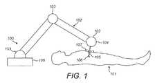
図1には、基台108、アーム102および器具105で構成される典型的な手術ロボット100が示されている。上記基台は、当該ロボットを支持し、かつ、それ自体も例えば手術室の床、手術室の天井、トロリー等に強固に取り付けられている。上記アームは、上記基台と上記器具との間を延びている。上記アームは当該アームの長さに沿って、上記手術器具を患者に対して所望の位置に配置するために用いられる複数のフレキシブルジョイント103によって関節駆動される。上記手術器具は、このロボットアームの先端部104に取り付けられている。上記手術器具は、ポート107で、手術部位にアクセスするように患者101の体内に進入する。上記器具は当該器具の先端部に、医療処置を行うためのエンドエフェクタ106を備えている。 FIG. 1 shows a typical
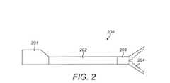
図2には、ロボット腹腔鏡下手術を実行するための典型的な手術器具200が示されている。この手術器具はベース201を備え、当該手術器具はベース201を介して上記ロボットアームに接続されている。ベース201と関節部203との間には、シャフト202が延びている。関節部203は、エンドエフェクタ204で終端する。図2では、エンドエフェクタ204として一対の鋸歯状のジョーが図示されている。関節部203により、エンドエフェクタ204がシャフト202に対して移動することが可能である。当該関節部により、エンドエフェクタ204の動きに少なくとも2の自由度が付与されることが望ましい。 FIG. 2 shows an exemplary
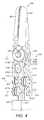
ロボット手術器具は長さが長く、外径が細い。通常、その長さは約40cmであり、直径は8mmである。図3には、ピッチジョイント301および2つのヨージョイント302によって、シャフト202に対してエンドエフェクタ204を移動させることができる公知の手術器具300の例が示されている。ジョイント301により、エンドエフェクタ204を、ピッチ軸心303を中心として回動させることが可能である。ジョイント302により、エンドエフェクタ204の各ジョーを、ヨー軸心304を中心として回動させることが可能である。ヨー軸心を中心として反対方向にこれらのジョーを回動させることにより、組織を把持および解除することが可能である。上記のジョイントは、ケーブル306,307および308によって駆動される。 Robot surgical instruments are long in length and thin in outer diameter. Usually, its length is about 40 cm and its diameter is 8 mm. FIG. 3 shows an example of a known
ベース201においてケーブル307および308に加えられる張力により、ヨー軸心304を中心としたエンドエフェクタのジョーの回動が生じる。上記の器具の長細い形態の結果として、ベース201においてケーブル307および308に加えられる張力を増幅させるために利用できるモーメントは制限されている。各ケーブルに加えることができる力は、その構造や、ケーブルがその末端でどのように固定されているかによって制限される。よって、エンドエフェクタのジョーがその間で物体を把持することができる力は制限されている。手術医が、組織を操作し、切断作業を行い、また針などの他の道具を掴むことを補助するために、エンドエフェクタの利用可能な把持力を増大させることが望ましい。 The tension applied to the
さらに、患者の皮膚を切開するサイズを最小限とし、患者体内における断裂を最小限に留めるために、器具の外径を小さくすることが望ましい。これにより、器具シャフトおよび関節部に収容できるケーブルのサイズが小さくなるので、エンドエフェクタに加えることができる力がさらに小さくなる。 In addition, it is desirable to reduce the outer diameter of the instrument in order to minimize the size of the incision through the patient's skin and minimize tearing within the patient. This reduces the size of the cable that can be accommodated in the instrument shaft and the joint, thereby further reducing the force that can be applied to the end effector.
器具の外径を小さくし、かつエンドエフェクタのジョーの把持力を高めるという競合するニーズを満たすことが望ましい。 It would be desirable to meet competing needs to reduce the outer diameter of the instrument and increase the gripping force of the end effector jaws.
本発明の一態様によると、シャフトと、第1エンドエフェクタエレメントと、前記第1エンドエフェクタエレメントを前記シャフトの先端部に連結する関節部であって、前記第1エンドエフェクタエレメントは当該関節部に対して移動可能である関節部と、前記シャフトの基端部において、第1アクチュエータを備える駆動機構であって、前記第1アクチュエータは第1の駆動エレメントの対によって前記第1エンドエフェクタエレメントに連結されており、前記第1の駆動エレメントの対は、前記第1アクチュエータによって前記第1の駆動エレメントの対のうちの第1駆動エレメントに加えられる張力が、前記第1エンドエフェクタエレメントを前記関節部に対して第1移動方向に移動させ、かつ、前記第1の駆動エレメントの対のうちの第2駆動エレメントに加えられる張力が、前記第1エンドエフェクタエレメントを前記関節部に対して第2移動方向に移動させるように構成されている駆動機構と、を備えるロボット手術器具であって、前記第1の駆動エレメントの対のうちの前記第1駆動エレメントは、前記第1アクチュエータと前記第1エンドエフェクタエレメントとの間に第1経路を有し、前記第1の駆動エレメントの対のうちの前記第2駆動エレメントは、前記第1アクチュエータと前記第1エンドエフェクタエレメントとの間に第2経路を有し、前記第1エンドエフェクタエレメントに対して前記第1移動方向に伝達される前記張力の大きさが、前記第2移動方向に伝達される前記張力の大きさよりも大きくなるように、前記第1経路は、前記第2経路よりも張力損失が小さいロボット手術器具が提供される。 According to an aspect of the present invention, a shaft, a first end effector element, and a joint portion that connects the first end effector element to a distal end portion of the shaft, the first end effector element being connected to the joint portion. A drive mechanism having a first actuator at a joint portion movable relative to the shaft and a proximal end portion of the shaft, wherein the first actuator is connected to the first end effector element by a pair of first drive elements The first drive element pair is configured such that tension applied to the first drive element of the first drive element pair by the first actuator causes the first end effector element to move to the joint portion. In the first movement direction and out of the pair of the first drive elements A drive mechanism configured to cause tension applied to the second drive element to move the first end effector element in a second movement direction with respect to the joint, the robotic surgical instrument comprising: The first drive element of the pair of first drive elements has a first path between the first actuator and the first end effector element, and the first drive element of the pair of first drive elements The second drive element has a second path between the first actuator and the first end effector element, and the tension of the tension transmitted to the first end effector element in the first movement direction. The first path is more tensioned than the second path so that the magnitude is greater than the magnitude of the tension transmitted in the second movement direction. Loss is small robotic surgical instrument is provided.
前記ロボット手術器具は、第2エンドエフェクタエレメントをさらに備え、前記関節部は、前記第2エンドエフェクタエレメントを前記シャフトの前記先端部に連結しており、前記第2エンドエフェクタエレメントは前記関節部に対して移動可能であり、前記駆動機構は第2アクチュエータを備え、前記第2アクチュエータは、第2の駆動エレメントの対によって前記第2エンドエフェクタエレメントに連結されており、前記第2の駆動エレメントの対は、前記第2アクチュエータによって前記第2の駆動エレメントの対のうちの第1駆動エレメントに加えられる張力が、前記第2エンドエフェクタエレメントを前記関節部に対して前記第2移動方向に移動させ、かつ、前記第2の駆動エレメントの対のうちの第2駆動エレメントに加えられる張力が、前記第2エンドエフェクタエレメントを前記関節部に対して前記第1移動方向に移動させるように構成されており、前記第2の駆動エレメントの対のうちの前記第1駆動エレメントは、前記第2アクチュエータと前記第2エンドエフェクタエレメントとの間に第3経路を有し、前記第2の駆動エレメントの対のうちの前記第2駆動エレメントは、前記第2アクチュエータと前記第2エンドエフェクタエレメントとの間に第4経路を有し、前記第2エンドエフェクタエレメントに対して前記第2移動方向に伝達される前記張力の大きさが、前記第1移動方向に伝達される前記張力の大きさよりも大きくなるように、前記第3経路は、前記第4経路よりも張力損失が小さい構成としてもよい。 The robotic surgical instrument further includes a second end effector element, the joint portion connects the second end effector element to the tip portion of the shaft, and the second end effector element is connected to the joint portion. The drive mechanism includes a second actuator, the second actuator being coupled to the second end effector element by a pair of second drive elements, In the pair, the tension applied to the first drive element of the second drive element pair by the second actuator causes the second end effector element to move in the second movement direction with respect to the joint portion. And added to the second drive element of the pair of second drive elements Tension is configured to move the second end effector element in the first movement direction with respect to the joint, and the first drive element of the second drive element pair includes: A third path is provided between the second actuator and the second end effector element, and the second drive element of the second drive element pair includes the second actuator and the second end effector element. And the magnitude of the tension transmitted in the second movement direction to the second end effector element is greater than the magnitude of the tension transmitted in the first movement direction. The third path may have a smaller tension loss than the fourth path.
前記ロボット手術器具の内部構造体と接触する前記第1経路の接触長さが、前記ロボット手術器具の内部構造体と接触する前記第2経路の接触長さよりも短くてもよい。前記ロボット手術器具の内部構造体と接触する前記第3経路の接触長さが、前記ロボット手術器具の内部構造体と接触する前記第4経路の接触長さよりも短くてもよい。 The contact length of the first path that contacts the internal structure of the robotic surgical instrument may be shorter than the contact length of the second path that contacts the internal structure of the robotic surgical instrument. The contact length of the third path that contacts the internal structure of the robotic surgical instrument may be shorter than the contact length of the fourth path that contacts the internal structure of the robotic surgical instrument.
前記第1経路の全体長さが、前記第2経路の全体長さよりも短くてもよい。前記第3経路の全体長さが、前記第4経路の全体長さよりも短くてもよい。 The overall length of the first path may be shorter than the overall length of the second path. The overall length of the third path may be shorter than the overall length of the fourth path.
前記第1経路は、前記第3経路と形状が一致してもよい。前記第2経路は、前記第4経路と形状が一致してもよい。 The first path may have the same shape as the third path. The second path may have the same shape as the fourth path.
前記第1の駆動エレメントの対のうちの前記第1駆動エレメントは、M個のプーリの周りを移動するように拘束されていてもよく、前記第1の駆動エレメントの対のうちの前記第2駆動エレメントは、N個のプーリの周りを移動するように拘束されていてもよい。このとき、M<Nである。一実施例では、M<N−lである。例えば、M=4であり、N=6である。 The first drive element of the first drive element pair may be constrained to move around M pulleys, and the second of the first drive element pair. The drive element may be constrained to move around the N pulleys. At this time, M <N. In one embodiment, M <N−1. For example, M = 4 and N = 6.
前記第2の駆動エレメントの対のうちの前記第1駆動エレメントは、J個のプーリの周りを移動するように拘束されていてもよく、前記第2の駆動エレメントの対のうちの前記第2駆動エレメントはK個のプーリの周りを移動するように拘束されていてもよい。このとき、J<Kである。一実施例では、J<K−lである。例えば、M=Jであり、N=Kである。 The first drive element of the second pair of drive elements may be constrained to move around J pulleys, and the second of the second pair of drive elements. The drive element may be constrained to move around K pulleys. At this time, J <K. In one embodiment, J <K−1. For example, M = J and N = K.
前記第1の駆動エレメントの対のうちの前記第1駆動エレメントの直径は、前記第1の駆動エレメントの対のうちの前記第2駆動エレメントの直径よりも大きくてもよい。前記第1の駆動エレメントの対のうちの前記第1駆動エレメントは、前記第1の駆動エレメントの対のうちの前記第2駆動エレメントよりも少ない数の、より太いストランドから構成されていてもよい。 The diameter of the first drive element of the first drive element pair may be greater than the diameter of the second drive element of the first drive element pair. The first drive element of the first pair of drive elements may be composed of a smaller number of thicker strands than the second drive element of the pair of first drive elements. .
前記第2の駆動エレメントの対のうちの前記第1駆動エレメントの直径は、前記第2の駆動エレメントの対のうちの前記第2駆動エレメントの直径よりも大きくてもよい。前記第2の駆動エレメントの対のうちの前記第1駆動エレメントは、前記第2の駆動エレメントの対のうちの前記第2駆動エレメントよりも少ない数の、より太いストランドから構成されていてもよい。 The diameter of the first drive element of the second pair of drive elements may be larger than the diameter of the second drive element of the pair of second drive elements. The first drive element of the second pair of drive elements may be composed of a smaller number of thicker strands than the second drive element of the second pair of drive elements. .
各前記駆動エレメントは、スポークを備えていてもよい。 Each driving element may comprise a spoke.
各前記駆動エレメントは、ケーブルであってもよい。 Each drive element may be a cable.
各前記駆動エレメントは、その経路に沿って圧縮力および張力に抵抗してもよい。 Each drive element may resist compressive forces and tensions along its path.
各前記駆動エレメントの対のうちの前記第1および第2駆動エレメントは、一体に形成されていてもよい。 The first and second drive elements of each pair of drive elements may be integrally formed.
前記第1エンドエフェクタエレメントは、第1軸心を中心として前記関節部に対して回動可能であってもよく、前記第1の駆動エレメントの対は、前記第1アクチュエータによって前記第1の駆動エレメントの対のうちの前記第1駆動エレメントに加えられる前記張力が、前記第1エンドエフェクタエレメントを、前記第1軸心を中心として第1回動方向に回動させ、かつ、前記第1の駆動エレメントの対のうちの前記第2駆動エレメントに加えられる前記張力が、前記第1エンドエフェクタエレメントを、前記第1軸心を中心として第2回動方向に回動させるように構成されていてもよい。 The first end effector element may be rotatable with respect to the joint portion about a first axis, and the pair of first drive elements is driven by the first actuator. The tension applied to the first drive element of the pair of elements causes the first end effector element to pivot about the first axis in a first rotational direction, and the first The tension applied to the second drive element of the pair of drive elements is configured to rotate the first end effector element in a second rotation direction about the first axis. Also good.
前記第2エンドエフェクタエレメントは、前記第1軸心を中心として前記関節部に対して回動可能であってもよく、前記第2の駆動エレメントの対は、前記第2アクチュエータによって前記第2の駆動エレメントの対のうちの前記第1駆動エレメントに加えられる張力が、前記第2エンドエフェクタエレメントを、前記第1軸心を中心として前記第2回動方向に回動させ、かつ、前記第2の駆動エレメントの対のうちの前記第2駆動エレメントに加えられる前記張力が、前記第2エンドエフェクタエレメントを、前記第1軸心を中心として前記第1回動方向に回動させるように構成されていてもよい。 The second end effector element may be rotatable with respect to the joint portion about the first axis, and the second drive element pair is formed by the second actuator. The tension applied to the first drive element of the pair of drive elements causes the second end effector element to rotate about the first axis in the second rotation direction, and the second The tension applied to the second drive element of the pair of drive elements is configured to rotate the second end effector element in the first rotation direction about the first axis. It may be.
前記ロボット手術器具は、前記第1アクチュエータによって前記第1の駆動エレメントの対のうちの前記第1駆動エレメントに加えられる張力が、前記第1エンドエフェクタエレメントを、前記第2エンドエフェクタエレメントに向かって回動させ、かつ、前記第2アクチュエータによって前記第2の駆動エレメントの対のうちの前記第1駆動エレメントに加えられる張力が、前記第2エンドエフェクタエレメントを、前記第1エンドエフェクタエレメントに向かって回動させるように構成されていてもよい。 In the robotic surgical instrument, tension applied to the first drive element of the pair of first drive elements by the first actuator moves the first end effector element toward the second end effector element. Tension that is rotated and applied to the first drive element of the second drive element pair by the second actuator causes the second end effector element to move toward the first end effector element. You may be comprised so that it may rotate.
前記ロボット手術器具は、前記第1アクチュエータによって前記第1の駆動エレメントの対のうちの前記第1駆動エレメントに加えられる張力が、前記第1エンドエフェクタエレメントを、前記第2エンドエフェクタエレメントから離れる方向に回動させ、かつ、前記第2アクチュエータによって前記第2の駆動エレメントの対のうちの前記第1駆動エレメントに加えられる張力が、前記第2エンドエフェクタエレメントを、前記第1エンドエフェクタエレメントから離れる方向に回動させるように構成されていてもよい。 The robot surgical instrument has a direction in which a tension applied to the first drive element of the pair of first drive elements by the first actuator moves the first end effector element away from the second end effector element. And tension applied to the first drive element of the second drive element pair by the second actuator separates the second end effector element from the first end effector element. It may be configured to rotate in the direction.
前記第1および第2エンドエフェクタエレメントは、エンドエフェクタの向かい合う第1および第2のジョーであってもよい。 The first and second end effector elements may be first and second jaws that face the end effector.
前記第1エンドエフェクタエレメントは、前記関節部に対して直線的に変位可能であってもよく、前記第1の駆動エレメントの対は、前記第1アクチュエータによって前記第1の駆動エレメントの対のうちの前記第1駆動エレメントに加えられる前記張力が、前記第1エンドエフェクタエレメントを、第1直線方向に直線的に変位させ、かつ、前記第1の駆動エレメントの対のうちの前記第2駆動エレメントに加えられる前記張力が、前記第1エンドエフェクタエレメントを、前記第1直線方向とは反対方向である第2直線方向に直線的に変位させるように構成されていてもよい。 The first end effector element may be linearly displaceable with respect to the joint portion, and the first drive element pair may be the first drive element pair by the first actuator. The tension applied to the first drive element linearly displaces the first end effector element in a first linear direction, and the second drive element of the pair of first drive elements The tension applied to the first end effector element may be configured to linearly displace the first end effector element in a second linear direction that is opposite to the first linear direction.
前記第2エンドエフェクタエレメントは、前記関節部に対して直線的に変位可能であってもよく、前記第2の駆動エレメントの対は、前記第2アクチュエータによって前記第2の駆動エレメントの対のうちの前記第1駆動エレメントに加えられる前記張力が、前記第2エンドエフェクタエレメントを、前記第1直線方向に直線的に変位させ、かつ、前記第2の駆動エレメントの対のうちの前記第2駆動エレメントに加えられる前記張力が、前記第2エンドエフェクタエレメントを、前記第2直線方向に直線的に変位させるように構成されていてもよい。 The second end effector element may be linearly displaceable with respect to the joint portion, and the pair of the second drive elements may be selected from the pair of the second drive elements by the second actuator. The tension applied to the first drive element causes the second end effector element to linearly displace in the first linear direction, and the second drive of the second drive element pair. The tension applied to the element may be configured to linearly displace the second end effector element in the second linear direction.
前記第1エンドエフェクタエレメントは、ステープラの一部であってもよい。前記第2エンドエフェクタエレメントは、ステープラの一部であってもよい。 The first end effector element may be a part of a stapler. The second end effector element may be a part of a stapler.
以下において、あくまでも例示的に、本発明について添付の図面を参照しながら説明する。 In the following, the present invention will be described by way of example only with reference to the accompanying drawings.
図4には、例示的なロボット手術器具の先端部の模式図が示されている。この手術器具は全体として、図2に示された一般的な形態を有する。換言すれば、この手術器具は、当該手術器具を手術用ロボットアームに連結するベース201を備える。この器具ベースは、当該器具ベースがロボットアームの末端に着脱可能に取り付けられるように、手術用ロボットアームの末端と協働的に設計されている。ベース201と関節部203との間に、シャフト202が延びている。関節部203は、その基端部においてシャフト202に連結されており、その先端部において、エンドエフェクタ204に取り付けるために適したアタッチメントに連結されている。前記シャフト202および関節部203はすべて中空状である。これにより、これらの部分に駆動エレメントを通して、エンドエフェクタ204を作動させることが可能である。また、手術器具の重量も低減される。関節部203の本体は、図をわかりやすくするために、図4から省略されている。 FIG. 4 shows a schematic diagram of the tip of an exemplary robotic surgical instrument. The surgical instrument as a whole has the general form shown in FIG. In other words, the surgical instrument includes a base 201 that connects the surgical instrument to a surgical robot arm. The instrument base is designed to cooperate with the distal end of the surgical robot arm such that the instrument base is removably attached to the distal end of the robot arm. A
前記器具の直径は8mm未満である。好適には、前記器具の直径は5mmである。前記器具の直径は5mm未満であってもよい。前記器具の直径は、前記シャフトの直径であってもよい。前記器具の直径は、前記関節部のプロフィールの直径であってもよい。好適には、前記関節部のプロフィールの直径は、前記シャフトの直径以下である。 The instrument has a diameter of less than 8 mm. Preferably, the instrument has a diameter of 5 mm. The instrument may have a diameter of less than 5 mm. The diameter of the instrument may be the diameter of the shaft. The diameter of the instrument may be the diameter of the joint profile. Preferably, the diameter of the joint profile is less than or equal to the diameter of the shaft.
図4のエンドエフェクタは、2つの向かい合うエンドエフェクタエレメント401および402を有し、これらは、その間で物体を操作するために協働することができる。エンドエフェクタは、このように機能することができる任意の適切な形状であってもよい。例えば、前記エンドエフェクタは、平らなジョー、鋸歯状のジョー、グリッパー、ピンセット、鋏、一対のブレード、ステープラ、クランプ、焼灼器のいずれであってもよい。図4に示されたエンドエフェクタエレメントは、対向する第1のジョー401および第2のジョー402である。 The end effector of FIG. 4 has two opposing
関節部203は、エンドエフェクタ204に前記器具のシャフト202に対して様々な姿勢を取らせることができる複数のジョイントを備える。第1ジョイント403(全体は図示せず)により、エンドエフェクタ204を全体として第1軸心404を中心として回動させることができる。この回動は、駆動エレメント(図示せず)によって駆動される。例えば、この回動は、ケーブルによって駆動されてもよい。第1軸心404は、シャフト405の長手方向軸心に対して横方向である。 The
第2ジョイント406により、第1エンドエフェクタエレメント401を、第2軸心407を中心として回動させることができる。第2軸心407は、第1軸心404に対して横方向である。第1の駆動エレメントの対409a,409bは、第2軸心407を中心とした第1エンドエフェクタエレメント401の回動を駆動する。前記第1の駆動エレメントの対は、第1駆動エレメント409aおよび第2駆動エレメント409bを備える。第1駆動エレメント409aに加えられる張力は、第1エンドエフェクタエレメント401を第2エンドエフェクタエレメント402に向かって回動させる。第2駆動エレメント409bに加えられる張力は、第1エンドエフェクタエレメント401を第2エンドエフェクタエレメント402から離れる方向に回動させる。 With the second joint 406, the first
第3ジョイント408により、第2エンドエフェクタエレメント402を、第2軸心407を中心として回動させることができる。第2の駆動エレメントの対410a,410bは、第2軸心407を中心とした第2エンドエフェクタエレメント402の回動を駆動する。第2の駆動エレメントの対は、第1駆動エレメント410aおよび第2駆動エレメント410bを備える。第1駆動エレメント410aに加えられる張力は、第2エンドエフェクタエレメント402を第1エンドエフェクタエレメント401に向かって回動させる。第2駆動エレメント410bに加えられる張力は、第2エンドエフェクタエレメント402を第1エンドエフェクタエレメント401から離れる方向に回動させる。 With the third joint 408, the second
図4に示された構成において、各ジョイントは、それぞれの駆動エレメントの対によって駆動される。換言すれば、各ジョイントは、専用の駆動エレメントの対によって駆動される。前記ジョイントは独立に駆動される。第1エンドエフェクタエレメント401および第2エンドエフェクタエレメント402は、第2および第3ジョイントによって、第2軸心407を中心として独立に回動可能である。このように、これらのエンドエフェクタエレメントは、第2および第3ジョイントによって、同一方向または反対方向に回動させてもよい。第1エンドエフェクタエレメント401は、第2軸心を中心として回動させてもよいが、第2エンドエフェクタエレメント402は、第2軸心を中心として回動させない。第2エンドエフェクタエレメント402は、第2軸心を中心として回動させてもよいが、第1エンドエフェクタエレメント401は、第2軸心を中心として回動させない。 In the configuration shown in FIG. 4, each joint is driven by a respective pair of drive elements. In other words, each joint is driven by a pair of dedicated drive elements. The joints are driven independently. The first
図4には、第2ジョイント406および第3ジョイント408により、同じ軸心407を中心とした回動が可能であるとして示されている。しかしながら、第2および第3ジョイントにより、代替的に、異なる軸心を中心としてエンドエフェクタエレメントを回動させることができるようにしてもよい。一方のエンドエフェクタエレメントの回動軸心は、他方のエンドエフェクタエレメントの回動軸心から、シャフト202の長手方向にずれていてもよい。一方のエンドエフェクタエレメントの回動軸心は、他方のエンドエフェクタエレメントの回動軸心から、シャフト202の長手方向に対して横方向にずれていてもよい。一方のエンドエフェクタエレメントの回動軸心は、他方のエンドエフェクタエレメントの回動軸心と平行でなくてもよい。エンドエフェクタエレメント401,402の回動軸心は、シャフトの長手方向に互いにずれていてもよく、かつ/またはシャフトの長手方向に対して垂直な方向に互いにずれていてもよく、かつ/または互いに角度を有していてもよい。これは、エンドエフェクタエレメントが互いに非対称な関係にある場合に望ましいといえる。例えば、電気手術エレメントにおいて、第1エンドエフェクタエレメントには電力を供給し、第2エンドエフェクタエレメントには電力を供給せずに第1エンドエフェクタエレメントから絶縁してもよい。これを補助するために、2つのエンドエフェクタエレメントの回動軸心は、シャフトの長手方向に対して垂直な方向にずれていてもよい。別の例において、第1エンドエフェクタエレメントはブレードであってもよく、第2エンドエフェクタエレメントは平坦な切断表面であってもよい。ブレードの使用を補助するために、前記2つのエンドエフェクタエレメントの回動軸心は、互いに角度を有していてもよい。 FIG. 4 shows that the second joint 406 and the third joint 408 can rotate around the
図4の手術器具は、プーリ機構をさらに備え、第1の駆動エレメントの対409a,409bおよび第2の対の駆動エレメン410a,410bは、このプーリ機構の周りで移動するように拘束されている。前記プーリ機構は3組のプーリを備える。第1の組のプーリ411は、第1軸心404を中心に回動可能である。これにより、第1の組のプーリ411は、第1ジョイント403と同一の軸心回りに回転する。第1の組のプーリ411は、第1ジョイント403のいずれかの側に配置された一対のプーリ411aおよび411bを備える。第1および第2の駆動エレメントの対は、第1ジョイント403を超えて延びて、それぞれ第2および第3ジョイント406,408に到達するように拘束されている。第1の駆動エレメントの対のうちの第1駆動エレメント409aがプーリ411aの一方の側を通り、第1の駆動エレメントの対のうちの第2駆動エレメント409bがプーリ411bの反対側を通っていることにより、第1軸心404を中心としてエンドエフェクタがどれだけ回動しても、第1の駆動エレメントの対の各駆動エレメント409a,409bの長さがそれぞれ同一に維持される。同様に、第2の駆動エレメントの対のうちの第1駆動エレメント410aがプーリ411bの一方の側を通り、第2の駆動エレメントの対のうちの第2駆動エレメント410bがプーリ411aの反対側を通っていることにより、第1軸心404を中心としたエンドエフェクタの回動にかかわらず、第2の駆動エレメントの対の各駆動エレメント410a,410bの長さが同一に維持される。 The surgical instrument of FIG. 4 further comprises a pulley mechanism, wherein the first
前記プーリ機構は、第2の組のプーリ412をさらに備える。前記第1の組のプーリ411は、第2の組のプーリ412とエンドエフェクタ204との間に位置している。第2の組のプーリ412は、第1ジョイント403のいずれかの側に配置された一対のプーリ412aおよび412bを備える。第1プーリ412aは、第1軸心404と平行な第3軸心414を中心に回動可能である。第3軸心414は、シャフトの長手方向およびシャフトの長手方向に対して横方向の両方向において、第1軸心404からずれていてもよい。第2プーリ412bは、第1軸心404と平行な第4軸心415を中心に回動可能である。第4軸心415は、シャフトの長手方向およびシャフトの長手方向に対して横方向の両方向において、第1軸心404からずれている。第3および第4軸心は、互いに平行かつ互いにずれている。第3軸心414および第4軸心415は、シャフトの長手方向に対して垂直な同一平面にある。第1プーリ412aおよび第2プーリ412bをずらすことにより、各プーリの周りに巻かれた前記駆動エレメントは、このプーリの周りに巻かれた後に前記シャフトの下方に延びることが可能である。第1および第2の駆動エレメントの対はそれぞれ、プーリ411aおよび412aの反対側の周りに巻き付くように拘束されている。第1および第2の駆動エレメントの対はそれぞれ、プーリ412aおよび412bの反対側の周りに巻き付くように拘束されている。これにより、第1軸心404を中心としたエンドエフェクタの回動にかかわらず、第1および第2の駆動エレメントの対が張られた状態で保たれる。 The pulley mechanism further includes a second set of
前記プーリ機構は、一対の方向転換プーリ413aおよび413bをさらに備える。方向転換プーリ413aおよび413bは、第1の組のプーリ411とエンドエフェクタ204との間に位置している。前記方向転換プーリは、駆動エレメント409a,409bの方向を第1の組のプーリ411から第2ジョイント406に変え、駆動エレメント410a,410bの方向を第1の組のプーリ411から第3ジョイント408に変えるように配置されている。これらの方向転換プーリにより、第1軸心404を中心としたエンドエフェクタの回動にかかわらず、第1および第2の駆動エレメントの対と第2および第3ジョイントとの接触量が同一に保たれる。換言すれば、前記第1および第2の駆動エレメントの対は、器具の構成にかかわらず、第2および第3ジョイントの周りに巻き付く量が同一に保たれる。また、これにより、エンドエフェクタの姿勢位置にかかわらず、第1および第2の駆動エレメントの対によって第2および第3ジョイント与えることができる回動範囲が同一に保たれる。 The pulley mechanism further includes a pair of
前記プーリ機構により、前記手術器具の全ての形態において、前記第1および第2の駆動エレメントの対が張られた状態に保たれ、前記関節部にまたは互いに引っかかることなく、かつ、前記第2および第3ジョイントの周りで十分な巻き付きを維持することができる。前記駆動エレメントの緩みを回避することによって、前記手術器具のジョイントを関節駆動する際に反動が生じない。これにより、前記手術器具の全ての形態において、前記手術器具の動きを完全に制御することができる。図4に示されたプーリ機構の代替的な配置を使用してもよい。使用するプーリの数をより少なく、またはより多くしてもよい。 The pulley mechanism keeps the pair of the first and second drive elements stretched in all the forms of the surgical instrument, without being caught by the joint part or each other, and the second and the second drive elements. Sufficient wrapping can be maintained around the third joint. By avoiding loosening of the drive element, no recoil occurs when the joint of the surgical instrument is articulated. Thereby, in all forms of the surgical instrument, the movement of the surgical instrument can be completely controlled. Alternative arrangements of the pulley mechanism shown in FIG. 4 may be used. Less or more pulleys may be used.
図5には、前記手術器具における第1の駆動エレメントの対409a,409bの経路が示されている。第1の駆動エレメントの対と、この第1の駆動エレメントの対が接触する部品のみが図示されている。関節部203およびエンドエフェクタエレメント401を備える前記器具の先端部は、図4に図示されているとおりである。シャフト202の下方にある前記駆動エレメントの範囲の全体は図示されておらず、符号501で示す部分において省略されている。前記器具構造において前記第1の駆動エレメントの対が接触する残りの部分は、器具201の基端部における器具インターフェースである。 FIG. 5 shows the path of the first
器具インターフェースは、前記ロボットアームから前記駆動エレメントに駆動力を伝達する駆動機構を備える。前記駆動機構は、複数のアクチュエータを備える。各アクチュエータは一対の駆動エレメントに固定されている。図5において、第1アクチュエータ507は、第1の駆動エレメントの対409a,409bに固定されている。各アクチュエータは、器具インターフェースエレメント(図5では図示せず)に固定されている。各器具インターフェースは、前記ロボットアームの対応する駆動アセンブリインターフェースエレメントと係合する。各アクチュエータは、直線状に変位可能である。これにより、前記ロボットアームは、以下のようにして前記エンドエフェクタエレメントに駆動力を伝達する。駆動アセンブリインターフェースエレメントの動作により、器具インターフェースエレメントが動作し、この器具インターフェースエレメントがアクチュエータを動作させ、このアクチュエータが駆動エレメントを動作させ、この駆動エレメントが前記関節部のジョイントを動作させ、このジョイントがエンドエフェクタエレメントを動作させる。第1の駆動エレメントの対のうちの第1駆動エレメント409aは、器具インターフェースにおいてプーリ502および503の周りを移動するように拘束されている。第1の駆動エレメントの対のうちの第2駆動エレメント409bは、器具インターフェースにおいてプーリ504,505および506の周りを移動するように拘束されている。これらのプーリは、前記第1の駆動エレメントの対を、シャフト202から第1アクチュエータ507へと案内するように作用する。 The instrument interface includes a driving mechanism that transmits a driving force from the robot arm to the driving element. The drive mechanism includes a plurality of actuators. Each actuator is fixed to a pair of drive elements. In FIG. 5, the
図6には、前記手術器具における第2の駆動エレメントの対410a,410bの経路が示されている。第2の駆動エレメントの対と、この第2の駆動エレメントの対が接触する部品のみが図示されている。関節部203およびエンドエフェクタエレメント402を備える前記器具の先端部は、図4に図示されているとおりである。シャフト202の下方にある前記駆動エレメントの範囲の全体は図示されておらず、符号501で示す部分において省略されている。前記器具構造において前記第2の駆動エレメントの対が接触する残りの部分は、器具201の基端部における器具インターフェースである。 FIG. 6 shows the path of the second
器具201の基端部における駆動機構の第2アクチュエータ607は、第2の駆動エレメントの対410a,410bに固定されている。第2の駆動エレメントの対のうちの第1駆動エレメント410aは、器具インターフェースにおいてプーリ602および603の周りを移動するように拘束されている。第2の駆動エレメントの対のうちの第2駆動エレメント410bは、器具インターフェースにおいてプーリ604,605および606の周りを移動するように拘束されている。これらのプーリは、前記第2の駆動エレメントの対を、シャフト202から第2アクチュエータ607へと案内するように作用する。 The
図7および図8には、ステープラエンドエフェクタの動作を駆動するために用いられる駆動エレメントの対710a,710bおよび809a,809bの経路が示されている。このステープラエンドエフェクタは、第1エンドエフェクタ部分701と、第2エンドエフェクタ部分802とを備える。第1エンドエフェクタ部分701は、ステープルの束714を収容するステープラブロック716を備える。また、第1エンドエフェクタ部分701は、ステープラアプリケータ715も備える。駆動エレメント710aおよび710bは、前記関節部からステープラブロック716へと通過し、ステープラアプリケータ715のいずれかの端部において終端している。駆動エレメント710aおよび710bはステープラアプリケータ715に堅固に取り付けられている。前記駆動エレメントは、ステープラブロック716の先端部においてプーリ713の周りに巻き付いている。ステープラアプリケータ715は、ステープラブロック716内で直線状に変位可能である。例えば、ステープラアプリケータ715は、ステープラブロック716のチャネル内またはレールに沿って摺動させてもよい。ステープラアプリケータ715は、前記関節部に対して直線状に変位可能である。ステープラアプリケータ715は、矢印Aで示される方向と、Aとは反対方向とに移動可能である。ステープラアプリケータ715は、移動するときにステープル714と係合する。これにより、ステープル714がステープラブロック716の外部に露出する。前記ステープルは、前記ステープラブロックが他の物体に押し付けられることにより閉じられる。 7 and 8 show the path of drive element pairs 710a, 710b and 809a, 809b used to drive the operation of the stapler end effector. The stapler end effector includes a first
第2エンドエフェクタ部分802は、ステープラブレード815を収容するステープラブロック814を備える。駆動エレメント809aおよび809bは、前記関節部からステープラブロック814へと通過し、ステープラブレード815のいずれかの端部において終端している。駆動エレメント809aおよび809bは、ステープラブレード815に堅固に取り付けられている。前記駆動エレメントは、ステープラブロック814の先端部においてプーリ816の周りに巻き付いている。ステープラブレード815は、ステープラブロック814内で直線状に変位可能である。例えば、ステープラブレード815は、ステープラブロック814のチャネル内またはレールに沿って摺動させてもよい。ステープラブレード815は、前記関節部に対して直線状に変位可能である。ステープラブレード815は、矢印Aで示される方向と、Aとは反対方向とに移動可能である。ステープラブレード815は、ステープラブロック814の外部に露出している。 The second
動作時において、ステープラブロック814とステープラブロック716との間で組織が挟持される。ステープラアプリケータ715は、駆動エレメント710aを引張することによって、ステープラエンドエフェクタ部分701の先端部からステープラエンドエフェクタ部分701の基端部へと引っ張られる。ステープラアプリケータ715は、ステープル714と係合し、これらのステープルをステープラブロック716の外部に露出させ、前記エンドエフェクタ部分の間に挟持された組織に露出させる。前記ステープルは前記組織を貫通して、他方のステープラブロック814に押し付けられたときに閉じられる。ステープラブレード815は、駆動エレメント809aを引張することによって、ステープラエンドエフェクタ部分802の先端部からステープラエンドエフェクタ部分802の基端部へと引っ張られる。これにより、ステープラブレード815は、前記2つのエンドエフェクタ部分の間に挟持された組織を切断する。 In operation, tissue is sandwiched between the
図7および図8において、各駆動エレメントは、前記関節部における2つのプーリの周りに巻き付けられた状態で示されている。駆動エレメント809a用のプーリは、プーリ810および811である。駆動エレメント809b用のプーリは、プーリ812および813である。駆動エレメント710a用のプーリは、プーリ711および712である。駆動エレメント710b用のプーリは、プーリ708および709である。これらのプーリにより、図4から図6のプーリ411a,411b,412aおよび412bについて図示されているように、前記エンドエフェクタを前記器具のシャフトに対して回動させることが可能である。前記器具シャフトに対する前記ステープラエンドエフェクタの動作の自由度をさらに大きくすることができるように、追加のプーリを使用してもよい。エンドエフェクタ部分701および802の一方または両方は、他方のエンドエフェクタ部分に対して回動可能であってもよい。これは、一方または各エンドエフェクタ部分にジョイント406と同等のジョイントと、そのジョイントの周りに巻き付けられる追加の駆動エレメントの対とを導入して、このジョイントを中心として前記関節部に対して前記エンドエフェクタ部分が回動できるようにすることによって実現してもよい。これにより、前記エンドエフェクタ部分を互いに開閉することができるので、その間に材料を挟持することが可能である。 7 and 8, each drive element is shown wound around two pulleys in the joint. The pulleys for
図5および図6,図7および図8では、前記駆動エレメントが接触する前記器具の部品のみが図示されている。前記シャフトの下方にある前記駆動エレメントの範囲は、地点501で示されているとおり省略されている。図7および図8において前記器具の基端部における前記器具の内部構造体は、図5および図6に示されているとおりである。前記駆動機構、および前記ロボットアームの駆動アセンブリインターフェースに対するその接続部は、図5および図6に示されているように動作する。 In FIG. 5 and FIG. 6, FIG. 7 and FIG. 8, only the parts of the instrument that the drive element contacts are shown. The range of the drive element below the shaft has been omitted as indicated by
図7および図8において、ステープル動作および切断動作は、ステープラアプリケータ715およびステープラブレード815を、図7および図8でAとして示された方向にエンドエフェクタの先端部からエンドエフェクタの基端部へと引っ張ることによって実施される。代替的な実施方法としては、ステープル動作および切断動作は、ステープラアプリケータ715およびステープラブレード815を、図7および図8でAとして示された方向とは反対方向にエンドエフェクタの基端部からエンドエフェクタの先端部へと引っ張ることによって実施される。代替的に、ステープラアプリケータ715およびステープラブレード815の一方を、エンドエフェクタの先端部から基端部へと引っ張ることによって作動させ、ステープラアプリケータ715およびステープラブレード815の他方を、エンドエフェクタの基端部から先端部へと引っ張ることによって作動させてもよい。 7 and 8, the stapling and cutting operations cause the
図4から図8の駆動エレメントは、関節部203のジョイントからシャフトを介して器具インターフェース201へと延びる細長い要素である。好適には、各駆動エレメントは、少なくとも、前記関節部の内部部品と器具インターフェースとに係合する領域において、その主要な延びに対して横方向に撓ませることが可能である。換言すれば、各駆動エレメントは、特定の領域においてその長手方向軸心に対して横方向に撓ませることができる。この可撓性により、前記駆動エレメントは、前記ジョイントおよびプーリなどの前記器具の内部構造体の周りに巻き付けることが可能である。前記駆動エレメントは全体として、その長手方向軸心に対して横方向に可撓性を有していてもよい。前記駆動エレメントは、その主要な延びに沿って撓ませることができない。前記駆動エレメントは、その長さに沿って加えられる圧縮力および張力に対抗する。換言すれば、前記駆動エレメントは、それらの長手方向軸心の方向に作用する圧縮力および張力に対抗する。これにより、前記駆動エレメントは、前記器具インターフェースから前記関節部のジョイントへと駆動力を伝達することが可能である。前記駆動エレメントはケーブルであってもよい。 The drive element of FIGS. 4-8 is an elongate element that extends from the joint of the joint 203 to the
各駆動エレメントの対は、その長さに沿って同一の形状およびサイズを有し、その長さに沿って同一の材料から構成されている均一な部品であってもよい。代替的に、各駆動エレメントの対は、異なる部分から構成されていてもよい。一実施例では、前記駆動エレメントにおいて、前記器具インターフェースの部品(プーリおよびインターフェースエレメントなど)と係合する部分は可撓性を有する。例えば、この部分はケーブルであってもよい。同様に、前記駆動エレメントにおいて、前記手術器具の先端部の部品(プーリおよび関節部のジョイントなど)と係合する部分は可撓性を有する。例えば、この部分はケーブルであってもよい。これら2つの可撓性部分の間には、スポークが設けられている。これにより、この例において、各駆動エレメントの対は、2本のスポークと、2つの可撓性部分とを備える。各駆動エレメントの対は、ループを形成している。このループは、スポークと可撓性部分とを交互に備える。前記2本のスポークは、大部分または全体が前記器具シャフトに囲まれている。先端側の可撓性部分は、一端部において一方のスポークの先端部で終端しており、他端部において他方のスポークの先端部で終端している。前記先端側の可撓性部分は、前記関節部の部品と係合する。基端側の可撓性部分は、一端部において一方のスポークの基端部で終端しており、他端部において他方のスポークの基端部で終端している。前記基端側の可撓性部分は、前記器具インターフェースの部品と係合する。前記スポークは、前記可撓性部分よりも固い。好適には、前記スポークは剛体である。前記スポークは、中空のチューブであってもよい。通常、前記スポークの直径は、可撓性部分の直径よりも大きい。前記可撓性部分は、前記スポークと連結される箇所で終端してもよい。代替的に、前記スポークは、前記可撓性部分の材料を包囲していてもよい。例えば、前記スポークは、可撓性のケーブルを覆う剛性の鞘であってもよい。 Each pair of drive elements may be a uniform part that has the same shape and size along its length and is composed of the same material along its length. Alternatively, each drive element pair may be composed of different parts. In one embodiment, the portion of the drive element that engages with parts of the instrument interface (such as pulleys and interface elements) is flexible. For example, this portion may be a cable. Similarly, in the drive element, a portion that engages with a component (such as a pulley and a joint of a joint portion) at the distal end portion of the surgical instrument has flexibility. For example, this portion may be a cable. Spokes are provided between these two flexible parts. Thus, in this example, each drive element pair comprises two spokes and two flexible portions. Each pair of drive elements forms a loop. The loop comprises alternating spokes and flexible portions. The two spokes are mostly or entirely surrounded by the instrument shaft. The flexible portion on the front end side terminates at one end of the tip of one spoke and terminates at the other end of the tip of the other spoke. The flexible portion on the distal end side engages with a component of the joint portion. The proximal-side flexible portion terminates at one end at the proximal end of one spoke and at the other end at the proximal end of the other spoke. The proximal flexible portion engages a part of the instrument interface. The spoke is harder than the flexible portion. Preferably, the spoke is a rigid body. The spoke may be a hollow tube. Usually, the diameter of the spoke is larger than the diameter of the flexible part. The flexible portion may terminate at a location where it is connected to the spoke. Alternatively, the spoke may surround the material of the flexible portion. For example, the spoke may be a rigid sheath that covers a flexible cable.
図4から図6において、第1の駆動エレメントの対409a,409bは、第2ジョイント406に固定されている。例えば、図4において、前記第1の駆動エレメントの対は、ボールおよびクリンプ終端によって、前記第2ジョイントに固定されている。また、前記第1の駆動エレメントの対は、第1アクチュエータ507にも固定されている。前記第1の駆動エレメントの対は一体に形成されていてもよい。例えば、これらは連続ケーブルであってもよい。代替的に、前記第1の駆動エレメントの対は、前記第2ジョイントに固定される箇所および/または前記第1アクチュエータに固定される箇所で途切れていてもよい。 4 to 6, the first
第2の駆動エレメントの対410a,410bは、第3ジョイント408に固定されている。例えば、前記第2の駆動エレメントの対は、ボールおよびクリンプ終端によって、前記第2ジョイントに固定されていてもよい。また、前記第2の駆動エレメントの対は、第2アクチュエータ607にも固定されている。 The second
前記第2の駆動エレメントの対は一体に形成されていてもよい。例えば、これらは連続ケーブルであってもよい。代替的に、前記第2の駆動エレメントの対は、前記第3ジョイントに固定される箇所および/または前記第2アクチュエータに固定される箇所で途切れていてもよい。 The pair of second drive elements may be integrally formed. For example, these may be continuous cables. Alternatively, the second drive element pair may be interrupted at a location fixed to the third joint and / or a location fixed to the second actuator.
図8において、駆動エレメント809aおよび809bは第1アクチュエータ507に固定されており、また、ステープラブレード815にも固定されている。この駆動エレメントの対は一体に形成されていてもよい。例えば、これらは連続ケーブルであってもよい。代替的に、この駆動エレメントの対は、ステープラブレード815に固定される箇所および/または第1アクチュエータ507に固定される箇所で途切れていてもよい。 In FIG. 8, the
図7において、駆動エレメント710aおよび710bは第2アクチュエータ607に固定されており、また、ステープラアプリケータ715にも固定されている。この駆動エレメントの対は一体に形成されていてもよい。例えば、これらは連続ケーブルであってもよい。代替的に、この駆動エレメントの対は、ステープラアプリケータ715に固定される箇所および/または第2アクチュエータ607に固定される箇所で途切れていてもよい。 In FIG. 7, the
前記駆動エレメントは、その長さに沿って作用する張力に対抗する。これにより、前記駆動アセンブリによってアクチュエータが駆動されたとき、このアクチュエータは前記駆動エレメントに張力を加える。図5および図6の場合、これにより、前記関節部においてこの駆動エレメントが終端する前記ジョイントに加えられる回転力が生じる。これにより、この回転力によって前記エンドエフェクタエレメントを回動させる。図7および図8の場合、これにより、前記エンドエフェクタエレメント(ステープラブレード815/ステープラアプリケータ715)に加えられる直線力が生じる。前記エンドエフェクタエレメントのこの回転力/直線力は、前記駆動エレメントの張力の損失により、前記器具インターフェースにおいて駆動エレメントに加えられる張力ほど大きくない。この張力の損失は、主に、前記駆動エレメントと、この駆動エレメントが、前記アクチュエータとこのアクチュエータが駆動する前記ジョイントとの間でその周りを移動するように拘束されている前記プーリとの間の摩擦によって引き起こされる。 The drive element resists tension acting along its length. Thus, when an actuator is driven by the drive assembly, the actuator applies tension to the drive element. In the case of FIGS. 5 and 6, this creates a rotational force applied to the joint where the drive element terminates at the joint. Thereby, the end effector element is rotated by this rotational force. In the case of FIGS. 7 and 8, this produces a linear force applied to the end effector element (
駆動エレメントの対の両エレメントが同一に構成されており、プーリの数およびサイズが同一の経路を有し、前記プーリの周りに巻きつけられた量が同一で、前記プーリ周りの方向における変化量が同一である場合、前記対の両駆動エレメントにおける張力損失は同一である。これにより、前記エンドエフェクタエレメントに加えられる最大移動(回動または直線)力は、前記エンドエフェクタエレメントの両移動方向について同一である。 Both elements of the pair of drive elements are configured identically, have the same number and size of pulleys, have the same amount of winding around the pulley, and the amount of change in the direction around the pulley Are the same, the tension loss in both drive elements of the pair is the same. Thereby, the maximum moving (rotating or linear) force applied to the end effector element is the same in both moving directions of the end effector element.
本明細書に記載した例において、前記アクチュエータとこのアクチュエータが駆動する前記ジョイントとの間における、駆動エレメントの対の各駆動エレメントの経路は非対称である。この結果、前記エンドエフェクタエレメントに加えられる最大移動力は、前記エンドエフェクタエレメントの2つの移動方向について異なっている。各エンドエフェクタに対して、各エンドエフェクタエレメントに対する優先移動方向が存在する。この優先移動方向は、最も重要なことには、前記器具の駆動機構によって最大張力が伝達される方向である。 In the example described herein, the path of each drive element of the drive element pair between the actuator and the joint that the actuator drives is asymmetric. As a result, the maximum moving force applied to the end effector element is different for the two moving directions of the end effector element. For each end effector, there is a preferential movement direction for each end effector element. This preferential movement direction is most importantly the direction in which maximum tension is transmitted by the drive mechanism of the instrument.
図4の例において、前記エンドエフェクタは一対のジョーである。これらのジョーは、その間で物体を把持するために用いられるので、各ジョーの優先回動方向は、これらのジョーを共に閉じる場合に影響する方向である。前記ジョーを開くことができる力はあまり重要ではない。よって、第1ジョー401の優先回動方向は第2ジョー402に向かう方向であり、第2ジョー402の優先回動方向は、第1ジョー401に向かう方向である。 In the example of FIG. 4, the end effector is a pair of jaws. Since these jaws are used to grip an object between them, the preferred pivoting direction of each jaw is the direction that affects the closing of these jaws together. The force that can open the jaws is not very important. Therefore, the priority rotation direction of the
他のエンドエフェクタについて、各エンドエフェクタエレメントに対する優先回動方向は、エンドエフェクタエレメントを互いから離すように開く場合に影響する方向であってもよい。例えば、クランプであるエンドエフェクタは、組織の2つの部分を離して保持することで開口を維持する2つの挟持エンドエフェクタエレメントを備えていてもよい。そして、このクランプによって維持された開口内の部位を、別の器具で操作してもよい。この場合、各挟持エンドエフェクタエレメントの優先回動方向は、他方の挟持エンドエフェクタエレメントから離れる方向である。別の例において、エンドエフェクタは、手術部位にクリップまたは結紮を適用してもよい。このクリップまたは結紮は付勢によって閉じられている。前記エンドエフェクタは、前記クリップまたは結紮を開き、または開いた状態に保持して手術部位に配置するための力を加える。この場合、各エンドエフェクタエレメントの優先回動方向は、他方のエンドエフェクタエレメントから離れる方向である。 For other end effectors, the preferential rotation direction for each end effector element may be a direction that affects the opening of the end effector elements away from each other. For example, an end effector that is a clamp may include two clamping end effector elements that maintain an opening by holding two portions of tissue apart. And you may operate the site | part in the opening maintained by this clamp with another instrument. In this case, the preferential rotation direction of each sandwiching end effector element is a direction away from the other sandwiching end effector element. In another example, the end effector may apply a clip or ligation to the surgical site. This clip or ligation is closed by bias. The end effector applies force to open or hold the clip or ligature and place it at the surgical site. In this case, the preferential rotation direction of each end effector element is a direction away from the other end effector element.
図7および図8の例において、前記エンドエフェクタはステープラである。前記2つのエンドエフェクタ部分は、その間に挟持された組織をステープルし、その後、ブレードを用いてこの組織を切断するために使用される。各エンドエフェクタ部分の優先直線方向は、ステープル動作およびブレード動作を実行させる方向である。換言すれば、図7および図8に示された配置におけるステープラブレード815およびステープラアプリケータ715の両方に対する優先直線方向は、前記エンドエフェクタの先端部から前記関節部へと方向Aに向かう方向である。前記ステープラブレードおよびステープラアプリケータをその初期位置にリセットする力はあまり重要ではない。前記ブレードおよびステープラが図7および図8に示された方向とは反対方向に切断およびステープルするように作動された場合、優先直線方向は、方向Aとは反対方向となる。 In the example of FIGS. 7 and 8, the end effector is a stapler. The two end effector portions are used to staple tissue sandwiched therebetween and then cut the tissue with a blade. The priority linear direction of each end effector portion is a direction in which the staple operation and the blade operation are executed. In other words, the preferred linear direction for both the
前記優先移動方向に前記第1エンドエフェクタエレメントの動作を行わせるために張力が加えられる前記第1の駆動エレメントの対の駆動エレメントは、前記優先移動方向に前記第2エンドエフェクタエレメントの動作を行わせるために張力が加えられる前記第2の駆動エレメントの対の駆動エレメントと対称な経路を有していてもよい。非優先移動方向に前記第1エンドエフェクタエレメントの動作を行わせるために張力が加えられる前記第1の駆動エレメントの対の駆動エレメントは、非優先移動方向に前記第2エンドエフェクタエレメントの動作を行わせるために張力が加えられる前記第2の駆動エレメントの対の駆動エレメントと対称な経路を有していてもよい。図5および図6の例において、駆動エレメント409aおよび駆動エレメント410aの経路は対称である。また、駆動エレメント409bおよび駆動エレメント410bの経路も対称である。これにより、2つのジョー401および402のそれぞれの閉鎖力は同一であり、2つのジョー401および402のそれぞれの開放力は同一である。 The pair of drive elements of the first drive element to which tension is applied to cause the first end effector element to move in the preferential movement direction performs the operation of the second end effector element in the preferential movement direction. There may be a path symmetrical to the drive elements of the pair of second drive elements to which tension is applied in order to achieve this. The pair of drive elements of the first drive element to which tension is applied in order to cause the first end effector element to move in the non-priority movement direction performs the operation of the second end effector element in the non-priority movement direction. There may be a path symmetrical to the drive elements of the pair of second drive elements to which tension is applied in order to achieve this. In the example of FIGS. 5 and 6, the paths of the
前記ロボットアームの端部リンクに対する前記エンドエフェクタの位置は、アクチュエータ507,607の変位量を測定することによって、または前記アクチュエータに固定された前記器具インターフェースエレメントの変位量を測定することによって、または前記器具インターフェースエレメントと係合した前記駆動アセンブリインターフェースエレメントの変位量を測定することによって決定してもよい。各変位量は、前記ロボットアームの端部リンクに対して一定位置にある位置センサを用いて測定される。各検出位置を、他の検出位置、前記駆動エレメントが移動するように拘束された前記器具の内部構造体(プーリなど)の公知の形態、前記駆動エレメントの長さ、ならびに前記エンドエフェクタエレメントの形状およびサイズと組み合わせて用いることで、前記ロボットアームの端部リンクに対する前記エンドエフェクタの位置を決定することが可能である。 The position of the end effector with respect to the end link of the robot arm is measured by measuring the displacement of the
本明細書に記載した例において、前記アクチュエータとこのアクチュエータが駆動する前記エレメントとの間における、駆動エレメントの対の各駆動エレメントの経路は非対称である。上記の機構を用いた前記エンドエフェクタの位置の決定は、前記駆動エレメントの長さが一定であると推定している。前記器具の内部構造体(プーリなど)との相互作用により、または伸長された結果、駆動エレメントの長さに変化があれば、決定されたエンドエフェクタエレメントの位置の精度が低下する。前記駆動エレメントが長いほど、この方法で決定される前記エンドエフェクタエレメントの位置が不正確となる。前記駆動エレメントが移動するように拘束された内部構造体の数が多いほど、この方法で決定される前記エンドエフェクタエレメントの位置が不正確となる。優先移動方向は、最も重要なことには、前記エンドエフェクタエレメントの検出位置が最も正確となる方向となるように選択してもよい。 In the example described herein, the path of each drive element in a pair of drive elements between the actuator and the element driven by the actuator is asymmetric. Determination of the position of the end effector using the above mechanism assumes that the length of the drive element is constant. Any change in the length of the drive element as a result of interaction with or extension of the instrument's internal structure (such as a pulley) reduces the accuracy of the determined position of the end effector element. The longer the drive element, the less accurate the position of the end effector element determined in this way. The greater the number of internal structures that are constrained to move the drive element, the less accurate the position of the end effector element determined in this manner. Most importantly, the preferential movement direction may be selected so that the detection position of the end effector element is the most accurate.
各駆動エレメントの対について、前記優先移動方向に前記エンドエフェクタエレメントの動作を行わせるために引張される前記駆動エレメントの経路の張力損失は、反対方向である前記非優先移動方向に前記エンドエフェクタエレメントの動作を行わせるために引張される前記駆動エレメントの経路の張力損失よりも低い。これは、以下のうちのいずれかまたはその組み合わせを用いて達成してもよい。 For each drive element pair, the tension loss in the path of the drive element that is pulled to cause the end effector element to move in the preferential movement direction is opposite to the non-preferential movement direction in the end effector element. It is lower than the tension loss of the path of the drive element that is tensioned to perform the operation. This may be achieved using any of the following or a combination thereof.
1. 前記優先移動方向に前記エンドエフェクタエレメントの動作を行わせるために引張される前記駆動エレメントの経路は、M個のプーリを越えて移動するように拘束されており、反対方向である前記非優先移動方向に前記エンドエフェクタエレメントの動作を行わせるために引張される前記駆動エレメントの経路は、N個のプーリを越えて移動するように拘束されている。このとき、M<Nである。好適には、M<N−lである。好適には、エンドエフェクタ204について、前記第1エンドエフェクタエレメントに対するMの値は、前記第2エンドエフェクタエレメントに対するMの値と同一である。 1. The path of the drive element that is pulled to cause the end effector element to move in the preferential movement direction is constrained to move beyond M pulleys, and the non-priority movement is in the opposite direction. The path of the drive element that is pulled to cause movement of the end effector element in a direction is constrained to move past N pulleys. At this time, M <N. Preferably, M <N−1. Preferably, for the
図5および図6の例において、ジョー401の閉鎖を行う第1の駆動エレメントの対のうちの第1駆動エレメントは、第1アクチュエータ507と第2ジョイント406との間で4個プーリを越えて移動するように拘束されており、一方で、ジョー401の開放を行う第1の駆動エレメントの対のうちの第2駆動エレメントは、第1アクチュエータ507と第2ジョイント406との間で6個のプーリを越えて移動するように拘束されている。同様に、ジョー402の閉鎖を行う第2の駆動エレメントの対のうちの第1駆動エレメントは、第2アクチュエータ607と第3ジョイント408との間で4個プーリを越えて移動するように拘束されており、一方で、ジョー402の開放を行う第2の駆動エレメントの対のうちの第2駆動エレメントは、第2アクチュエータ507と第3ジョイント408との間で6個のプーリを越えて移動するように拘束されている。 In the example of FIGS. 5 and 6, the first drive element of the first drive element pair that closes the
図7の例において、引張されたときステープル動作を行う前記駆動エレメントの対のうちの第1駆動エレメント710aは、第2アクチュエータ607とステープラアプリケータ715との間で4個プーリを越えて移動するように拘束されており、一方で、前記駆動エレメントの対のうちの第2駆動エレメント710bは、第2アクチュエータ607とステープラアプリケータとの間で6個のプーリを越えて移動するように拘束されている。同様に、引張されたとき切断動作を行う前記駆動エレメントの対のうちの第1駆動エレメント809aは、第1アクチュエータ507とステープラブレード815との間で4個プーリを越えて移動するように拘束されており、一方で、前記駆動エレメントの対のうちの第2駆動エレメント809bは、第1アクチュエータ507とステープラブレード815との間で6個のプーリを越えて移動するように拘束されている。 In the example of FIG. 7, the
2. 前記優先移動方向に前記エンドエフェクタエレメントの動作を行わせるために引張される前記駆動エレメントの経路は、反対方向の前記非優先移動方向に前記エンドエフェクタエレメントの動作を行わせるために引張される前記駆動エレメントの経路と比較すると、プーリの周りの巻き長さが短くなるように拘束されている。換言すれば、前記プーリと接触している駆動エレメントの合計長さは、前記優先移動方向に前記エンドエフェクタエレメントの動作を行わせるために引張される前記駆動エレメントの経路について、他方の駆動エレメントよりも短い。よって、前記優先移動方向に前記エンドエフェクタエレメントの動作を行わせるために引張される駆動エレメントが受ける摩擦は、他方の駆動エレメントが受ける摩擦よりも小さい。好適には、エンドエフェクタ204について、前記優先回動方向にエンドエフェクタエレメント401,402の回動を生じさせるように引張される両駆動エレメント409a,410aの前記プーリ周りの巻き長さは同一であり、かつ、反対方向の非優先回動方向にエンドエフェクタエレメント401,402の回動を生じさせるように引張される両駆動エレメント409b,410bの前記プーリ周りの巻き長さは同一である。 2. The path of the drive element that is pulled to cause movement of the end effector element in the preferential movement direction is pulled to cause movement of the end effector element in the non-priority movement direction in the opposite direction. Compared with the path of the drive element, the winding length around the pulley is constrained to be short. In other words, the total length of the drive elements that are in contact with the pulley is greater than the other drive element in the path of the drive element that is pulled to cause the end effector element to move in the preferential movement direction. Also short. Therefore, the friction received by the drive element pulled to cause the end effector element to move in the preferential movement direction is smaller than the friction received by the other drive element. Preferably, for the
図5および図6ならびに図7および図8の例において、各駆動エレメントの対は、前記器具の基端部において180°方向を変える。前記第1および第2の駆動エレメントの対は、この方向変更を行うために、それぞれプーリ506および606の周りを移動するように拘束されている。前記駆動エレメントがこれらのプーリ周りで巻き付く量は、方向変更により、他のいずれのプーリ周りよりも大きくなる。この180°の方向変更は、全体として、前記非優先移動方向に前記エンドエフェクタエレメントの動作を行わせるために引張される前記駆動エレメントの経路において生じる。図7および図8においても、各駆動エレメントの対は、前記エンドエフェクタにおいて、前記器具の先端部で180°方向を変える。駆動エレメント809bおよび710bは、この方向変更を行うために、それぞれプーリ816および713の周りを移動するように拘束されている。前記駆動エレメントがこれらのプーリ周りで巻き付く量は、全体として、前記非優先直線方向に前記エンドエフェクタエレメントの直線変位を行わせるために引張される前記駆動エレメントの経路において生じる。 In the examples of FIGS. 5 and 6 and FIGS. 7 and 8, each drive element pair changes direction by 180 ° at the proximal end of the instrument. The pair of first and second drive elements are constrained to move around pulleys 506 and 606, respectively, to effect this change of direction. The amount that the drive element wraps around these pulleys is greater than around any other pulley due to the change in direction. This 180 ° direction change generally occurs in the path of the drive element that is pulled to cause the end effector element to move in the non-priority movement direction. Also in FIGS. 7 and 8, each pair of drive elements changes 180 ° direction at the tip of the instrument at the end effector. Drive
3. 前記優先移動方向に前記エンドエフェクタエレメントの動作を行わせるために引張される前記駆動エレメントの経路の全体長さは、前記非優先移動方向に前記エンドエフェクタエレメントの動作を行わせるために引張される前記駆動エレメントの経路の全体長さよりも短い。これにより、前記駆動エレメントの伸長により生じる張力の損失は、非優先経路よりも優先経路において小さくなる。 3. The overall length of the path of the drive element that is pulled to cause the end effector element to move in the preferential movement direction is pulled to cause the end effector element to move in the non-priority movement direction. It is shorter than the entire length of the path of the drive element. Thereby, the loss of tension caused by the extension of the drive element is smaller in the priority path than in the non-priority path.
4. 前記優先移動方向に前記エンドエフェクタエレメントの動作を行わせるために引張される前記駆動エレメントの構造は、前記非優先移動方向前記エンドエフェクタエレメントの動作を行わせるために引張される前記駆動エレメントの構造とは異なっていてもよい。前記非優先移動方向前記エンドエフェクタエレメントの動作を行わせる前記駆動エレメントに用いられる駆動エレメントは、他方の駆動エレメントに用いるものよりも、直径が小さくてもよい。より薄い駆動エレメントを用いることにより、前記器具の内部で占める空間が小さくなる。前記器具の内部、特に関節部203の空間は、極めて限られている。よって、これにより、他方の駆動エレメントにより厚い駆動エレメントを使用するための空間が得られる。より厚い駆動エレメントは、より薄い駆動エレメントよりも、伸長または破断するまでに大きな力に耐えることができる。すなわち、より厚い駆動エレメントは、より薄い駆動エレメントと比べると、付加に耐えるためにより適している。より薄い駆動エレメントは、摩耗し得る、より厚い駆動エレメントと比べると、より小さな曲げ半径で方向変更するためにより適している。よって、より薄い駆動エレメントは、より多くのプーリの周りを移動するように拘束された駆動エレメントの経路により適している。 4). The structure of the drive element pulled to cause the end effector element to move in the preferential movement direction is the structure of the drive element pulled to cause the end effector element to move in the non-priority movement direction. May be different. The drive element used for the drive element that performs the operation of the end effector element in the non-priority movement direction may have a smaller diameter than that used for the other drive element. By using a thinner drive element, the space occupied within the instrument is reduced. The space inside the instrument, particularly the joint 203, is extremely limited. Thus, this provides a space for using a thicker drive element with the other drive element. Thicker drive elements can withstand greater forces before stretching or breaking than thinner drive elements. That is, a thicker drive element is better suited to withstand the addition than a thinner drive element. Thinner drive elements are more suitable for turning with a smaller bending radius compared to thicker drive elements that can wear. Thus, a thinner drive element is better suited for a drive element path that is constrained to move around more pulleys.
5. 前記優先移動方向に前記エンドエフェクタエレメントの動作を生じさせる前記駆動エレメントに用いる駆動エレメントは、他方の駆動エレメントに用いるものと比べると、より少ない数のより太いストランドから構成されていてもよい。他方の駆動エレメントは、より多くの数のより薄いストランドから構成されている。両駆動エレメントは同一の断面積を有していてもよい。両駆動エレメントの長手方向の剛性および強度は同程度であってもよい。 5). The drive element used for the drive element that causes the end effector element to move in the preferential movement direction may be composed of a smaller number of thicker strands than that used for the other drive element. The other drive element is composed of a larger number of thinner strands. Both drive elements may have the same cross-sectional area. The longitudinal stiffness and strength of both drive elements may be similar.
より少ない数のより太いストランドを有する駆動エレメントは、降伏応力がより高い。これにより、この駆動エレメントはより大きな力に耐えることができるので、付加に耐えるためにより適している。したがって、この駆動エレメントは、非優先経路と比べると、エンドエフェクタエレメントに大きな力を伝達する優先経路に用いられる。好適には、この駆動エレメントは、上記の項目1および2で述べたものよりも、より少ない数のプーリを越えて移動するように拘束され、かつ/またはプーリ周りの巻き長さがより短い。当該駆動エレメントは、より多くのより薄いストランドを有する駆動エレメントと比べると、可撓性が低く摩耗が生じやすいので、方向変更が少なく前記器具の内部構造体との接触が少ない駆動エレメントの経路により適している。 A drive element with a smaller number of thicker strands has a higher yield stress. Thereby, the drive element can withstand greater forces and is therefore more suitable for withstanding the addition. Therefore, this drive element is used for the priority path for transmitting a large force to the end effector element as compared with the non-priority path. Preferably, the drive element is constrained to move over a smaller number of pulleys and / or has a shorter winding length around the pulleys than those described in items 1 and 2 above. The drive element is less flexible and more prone to wear than a drive element with more thin strands, so that the drive element path is less likely to change direction and less contact with the instrument internal structure. Is suitable.
より多くのより薄いストランドを有する駆動エレメントは、降伏応力がより低い。これにより、この駆動エレメントは、より少ない数のより太いストランドを有する駆動エレメントと同じだけの力に耐えることができない。したがって、この駆動エレメントは、非優先経路に用いられる。好適には、この駆動エレメントは、上記の項目1および2で述べたものよりも、より多くの数のプーリを越えて移動するように拘束され、かつ/またはプーリ周りの巻き長さがより長い。当該駆動エレメントは、より少ない数のより太いストランドを有する駆動エレメントと比べると、可撓性が高く摩耗が生じづらい。これらの特性により、より多くのより薄いストランドを有する駆動エレメントは、より多くのプーリの周りを移動するように拘束され、かつ/またはより多くの方向変更が行われる駆動エレメントの経路により適している。その可撓性により、こうした方向変更は、より小さな半径で行うことが可能である。したがって、当該駆動エレメントは、非優先経路により適している。 A drive element with more thinner strands has a lower yield stress. Thereby, this drive element cannot withstand as much force as a drive element with a smaller number of thicker strands. Therefore, this drive element is used for the non-priority path. Preferably, the drive element is constrained to move over a greater number of pulleys and / or has a longer winding length around the pulleys than those described in items 1 and 2 above. . The drive element is more flexible and less prone to wear than a drive element having a smaller number of thicker strands. Due to these properties, drive elements with more and thinner strands are more suitable for the drive element paths that are constrained to move around more pulleys and / or more direction changes are made. . Due to its flexibility, such direction changes can be made with a smaller radius. Therefore, the drive element is more suitable for non-priority paths.
上記のアプローチのいずれか1つまたはその組み合わせを用いて、所与の数のジョイント、駆動エレメントおよびプーリに対して、優先作動(閉鎖または開放、一方向または他方向への直線変位など)を実施するためにエンドエフェクタに伝達される力が、非優先作動を実施するためのエンドエフェクタに伝達される力を低減することで最大化されるように、前記器具用の非対称の駆動機構を構成してもよい。 Perform preferential operation (closed or opened, linear displacement in one or the other direction) for a given number of joints, drive elements and pulleys using any one or combination of the above approaches The asymmetric drive mechanism for the instrument is configured so that the force transmitted to the end effector is maximized by reducing the force transmitted to the end effector for performing the non-priority operation. May be.
前記器具は、非手術目的に使用することが可能である。例えば、美容処置に用いることが可能である。 The instrument can be used for non-surgical purposes. For example, it can be used for cosmetic treatment.
本明細書において、出願人は、本明細書に記載した各構成、およびそれらの構成の2つ以上の任意の組み合わせを、そうした構成または組み合わせが当業者の技術常識に照らして全体として本明細書に基づいて実施可能である範囲において、個別に開示している。そうした構成または構成の組み合わせは、本明細書に開示されたいずれの課題を解決するかどうかによるものではなく、また、本願の請求の範囲を限定するものでもない。本発明の態様は、そうした個別の構成または構成の組み合わせのうちのいずれから構成されてもよいということを出願人は表明する。上述の説明を考慮すると、当業者にとって、本発明の範囲内で様々な変更を施してもよいということが明白であろう。 In this specification, the applicant refers to each of the configurations described herein, and any combination of two or more of those configurations as a whole in the light of the common general knowledge of those skilled in the art. To the extent that it can be implemented based on the above. Such a configuration or combination of configurations does not depend on whether any of the problems disclosed herein are solved, and does not limit the scope of the claims of the present application. Applicants express that aspects of the present invention may consist of any such individual configuration or combination of configurations. In view of the foregoing description it will be evident to a person skilled in the art that various modifications may be made within the scope of the invention.
Claims (31)
Translated fromJapanese第1エンドエフェクタエレメントと、
前記第1エンドエフェクタエレメントを前記シャフトの先端部に連結する関節部であって、前記第1エンドエフェクタエレメントは当該関節部に対して移動可能である関節部と、
前記シャフトの基端部において、第1アクチュエータを備える駆動機構であって、前記第1アクチュエータは第1の駆動エレメントの対によって前記第1エンドエフェクタエレメントに連結されており、前記第1の駆動エレメントの対は、前記第1アクチュエータによって前記第1の駆動エレメントの対のうちの第1駆動エレメントに加えられる張力が、前記第1エンドエフェクタエレメントを前記関節部に対して第1移動方向に移動させ、かつ、前記第1の駆動エレメントの対のうちの第2駆動エレメントに加えられる張力が、前記第1エンドエフェクタエレメントを前記関節部に対して第2移動方向に移動させるように構成されている駆動機構と、
を備えるロボット手術器具であって、
前記第1の駆動エレメントの対のうちの前記第1駆動エレメントは、前記第1アクチュエータと前記第1エンドエフェクタエレメントとの間に第1経路を有し、前記第1の駆動エレメントの対のうちの前記第2駆動エレメントは、前記第1アクチュエータと前記第1エンドエフェクタエレメントとの間に第2経路を有し、前記第1エンドエフェクタエレメントに対して前記第1移動方向に伝達される前記張力の大きさが、前記第2移動方向に伝達される前記張力の大きさよりも大きくなるように、前記第1経路は、前記第2経路よりも張力損失が小さいロボット手術器具。A shaft,
A first end effector element;
A joint that connects the first end effector element to a tip of the shaft, wherein the first end effector element is movable with respect to the joint;
A drive mechanism including a first actuator at a base end portion of the shaft, wherein the first actuator is connected to the first end effector element by a pair of first drive elements, and the first drive element The tension applied to the first drive element of the first drive element pair by the first actuator causes the first end effector element to move in the first movement direction with respect to the joint portion. The tension applied to the second drive element of the pair of first drive elements is configured to move the first end effector element in the second movement direction with respect to the joint portion. A drive mechanism;
A robotic surgical instrument comprising:
The first drive element of the pair of first drive elements has a first path between the first actuator and the first end effector element, and the first drive element of the pair of first drive elements The second drive element has a second path between the first actuator and the first end effector element, and the tension transmitted to the first end effector element in the first movement direction. The first path is a robotic surgical instrument in which the tension loss is smaller than that of the second path so that the magnitude of is larger than the magnitude of the tension transmitted in the second movement direction.
前記関節部は、前記第2エンドエフェクタエレメントを前記シャフトの前記先端部に連結しており、前記第2エンドエフェクタエレメントは前記関節部に対して移動可能であり、
前記駆動機構は第2アクチュエータを備え、前記第2アクチュエータは、第2の駆動エレメントの対によって前記第2エンドエフェクタエレメントに連結されており、前記第2の駆動エレメントの対は、前記第2アクチュエータによって前記第2の駆動エレメントの対のうちの第1駆動エレメントに加えられる張力が、前記第2エンドエフェクタエレメントを前記関節部に対して前記第2移動方向に移動させ、かつ、前記第2の駆動エレメントの対のうちの第2駆動エレメントに加えられる張力が、前記第2エンドエフェクタエレメントを前記関節部に対して前記第1移動方向に移動させるように構成されており、
前記第2の駆動エレメントの対のうちの前記第1駆動エレメントは、前記第2アクチュエータと前記第2エンドエフェクタエレメントとの間に第3経路を有し、前記第2の駆動エレメントの対のうちの前記第2駆動エレメントは、前記第2アクチュエータと前記第2エンドエフェクタエレメントとの間に第4経路を有し、前記第2エンドエフェクタエレメントに対して前記第2移動方向に伝達される前記張力の大きさが、前記第1移動方向に伝達される前記張力の大きさよりも大きくなるように、前記第3経路は、前記第4経路よりも張力損失が小さいロボット手術器具。The robotic surgical instrument according to claim 1, further comprising a second end effector element,
The joint portion connects the second end effector element to the tip portion of the shaft, and the second end effector element is movable with respect to the joint portion;
The drive mechanism includes a second actuator, and the second actuator is connected to the second end effector element by a pair of second drive elements, and the pair of second drive elements is the second actuator. Tension applied to the first drive element of the second drive element pair by the second end effector element with respect to the joint in the second movement direction, and the second drive element A tension applied to the second drive element of the pair of drive elements is configured to move the second end effector element in the first movement direction relative to the joint;
The first drive element of the second drive element pair has a third path between the second actuator and the second end effector element, and the second drive element pair of the second drive element pair. The second drive element has a fourth path between the second actuator and the second end effector element, and the tension transmitted to the second end effector element in the second movement direction. The third path is a robotic surgical instrument in which the third path has a smaller tension loss than the fourth path so that the magnitude of the tension is greater than the magnitude of the tension transmitted in the first movement direction.
Applications Claiming Priority (3)
| Application Number | Priority Date | Filing Date | Title |
|---|---|---|---|
| GB1617448.4AGB2554915B (en) | 2016-10-14 | 2016-10-14 | Driving arrangement for articulating a surgical instrument |
| GB1617448.4 | 2016-10-14 | ||
| PCT/GB2017/053038WO2018069679A1 (en) | 2016-10-14 | 2017-10-06 | Driving arrangement for articulating a surgical instrument |
Publications (3)
| Publication Number | Publication Date |
|---|---|
| JP2019530530Atrue JP2019530530A (en) | 2019-10-24 |
| JP2019530530A5 JP2019530530A5 (en) | 2020-11-12 |
| JP7018441B2 JP7018441B2 (en) | 2022-02-10 |
Family
ID=57680676
Family Applications (1)
| Application Number | Title | Priority Date | Filing Date |
|---|---|---|---|
| JP2019519987AActiveJP7018441B2 (en) | 2016-10-14 | 2017-10-06 | Drive arrangement for joint driving surgical instruments |
Country Status (6)
| Country | Link |
|---|---|
| US (1) | US11129686B2 (en) |
| EP (3) | EP3525710B1 (en) |
| JP (1) | JP7018441B2 (en) |
| CN (1) | CN110121308B (en) |
| GB (1) | GB2554915B (en) |
| WO (1) | WO2018069679A1 (en) |
Cited By (6)
| Publication number | Priority date | Publication date | Assignee | Title |
|---|---|---|---|---|
| JP6991637B1 (en)* | 2020-09-01 | 2022-01-13 | リバーフィールド株式会社 | Surgical tool |
| WO2023229353A1 (en)* | 2022-05-23 | 2023-11-30 | 주식회사 리브스메드 | End tool of surgical instrument and electrocauterization surgical instrument comprising same |
| JP2024518756A (en)* | 2021-04-23 | 2024-05-02 | リブスメド インコーポレーテッド | End tool for surgical instrument and surgical instrument equipped with same |
| JP2024526727A (en)* | 2021-07-16 | 2024-07-19 | リブスメド インコーポレーテッド | End tool for surgical instrument and surgical instrument equipped with same |
| US12150663B2 (en) | 2021-07-16 | 2024-11-26 | Livsmed Inc. | End tool of surgical instrument, and electrocauterization surgical instrument comprising same |
| US12390266B2 (en) | 2022-05-23 | 2025-08-19 | Livsmed Inc. | End tool of surgical instrument and electrocauterization surgical instrument comprising same |
Families Citing this family (65)
| Publication number | Priority date | Publication date | Assignee | Title |
|---|---|---|---|---|
| US9232959B2 (en) | 2007-01-02 | 2016-01-12 | Aquabeam, Llc | Multi fluid tissue resection methods and devices |
| US12290277B2 (en) | 2007-01-02 | 2025-05-06 | Aquabeam, Llc | Tissue resection with pressure sensing |
| ES2769535T3 (en) | 2008-03-06 | 2020-06-26 | Aquabeam Llc | Tissue ablation and cauterization with optical energy carried in a fluid stream |
| EP3351196A1 (en) | 2012-02-29 | 2018-07-25 | Procept Biorobotics Corporation | Automated image-guided tissue resection and treatment |
| US10231867B2 (en) | 2013-01-18 | 2019-03-19 | Auris Health, Inc. | Method, apparatus and system for a water jet |
| WO2014201165A1 (en) | 2013-06-11 | 2014-12-18 | Auris Surgical Robotics, Inc. | System for robotic assisted cataract surgery |
| US10426661B2 (en) | 2013-08-13 | 2019-10-01 | Auris Health, Inc. | Method and apparatus for laser assisted cataract surgery |
| US10076348B2 (en) | 2013-08-15 | 2018-09-18 | Intuitive Surgical Operations, Inc. | Rotary input for lever actuation |
| US10550918B2 (en) | 2013-08-15 | 2020-02-04 | Intuitive Surgical Operations, Inc. | Lever actuated gimbal plate |
| US20160287279A1 (en) | 2015-04-01 | 2016-10-06 | Auris Surgical Robotics, Inc. | Microsurgical tool for robotic applications |
| US9949749B2 (en) | 2015-10-30 | 2018-04-24 | Auris Surgical Robotics, Inc. | Object capture with a basket |
| US10231793B2 (en) | 2015-10-30 | 2019-03-19 | Auris Health, Inc. | Object removal through a percutaneous suction tube |
| US9955986B2 (en) | 2015-10-30 | 2018-05-01 | Auris Surgical Robotics, Inc. | Basket apparatus |
| EP3484397B1 (en) | 2016-07-14 | 2024-07-24 | Intuitive Surgical Operations, Inc. | Multi-cable medical instrument |
| WO2018094191A1 (en) | 2016-11-21 | 2018-05-24 | Intuitive Surgical Operations, Inc. | Cable length conserving medical instrument |
| US10357321B2 (en) | 2017-02-24 | 2019-07-23 | Intuitive Surgical Operations, Inc. | Splayed cable guide for a medical instrument |
| CN108934160B (en) | 2017-03-28 | 2021-08-31 | 奥瑞斯健康公司 | Shaft actuating handle |
| EP3606400B1 (en) | 2017-04-07 | 2022-03-09 | Auris Health, Inc. | Patient introducer alignment |
| US10285574B2 (en) | 2017-04-07 | 2019-05-14 | Auris Health, Inc. | Superelastic medical instrument |
| WO2019118336A1 (en) | 2017-12-14 | 2019-06-20 | Intuitive Surgical Operations, Inc. | Medical tools having tension bands |
| EP3761897A4 (en) | 2018-03-07 | 2021-11-24 | Intuitive Surgical Operations, Inc. | LOW-FRICTION MEDICAL TOOLS WITH SMALL PROFILE AND ASSEMBLY-FRIENDLY COMPONENTS |
| US11992286B2 (en)* | 2018-03-07 | 2024-05-28 | Intuitive Surgical Operations, Inc. | Low-friction medical tools having roller-assisted tension members |
| US12082900B2 (en) | 2018-03-07 | 2024-09-10 | Intuitive Surgical Operations, Inc. | Low-friction, small profile medical tools having easy-to-assemble components |
| WO2019199827A1 (en) | 2018-04-10 | 2019-10-17 | Intuitive Surgical Operations, Inc. | Articulable medical devices having flexible wire routing |
| JP7267309B2 (en) | 2018-06-07 | 2023-05-01 | オーリス ヘルス インコーポレイテッド | Robotic medical system with high-strength instruments |
| JP7391886B2 (en)* | 2018-06-28 | 2023-12-05 | オーリス ヘルス インコーポレイテッド | Medical system incorporating pulley sharing |
| US11259798B2 (en) | 2018-07-16 | 2022-03-01 | Intuitive Surgical Operations, Inc. | Medical devices having tissue grasping surfaces and features for manipulating surgical needles |
| US11612447B2 (en) | 2018-07-19 | 2023-03-28 | Intuitive Surgical Operations, Inc. | Medical devices having three tool members |
| WO2020036685A1 (en) | 2018-08-15 | 2020-02-20 | Auris Health, Inc. | Medical instruments for tissue cauterization |
| WO2020036686A1 (en) | 2018-08-17 | 2020-02-20 | Auris Health, Inc. | Bipolar medical instrument |
| CN112770689B (en) | 2018-09-26 | 2024-07-19 | 奥瑞斯健康公司 | Systems and instruments for suction and irrigation |
| US11576738B2 (en) | 2018-10-08 | 2023-02-14 | Auris Health, Inc. | Systems and instruments for tissue sealing |
| US12048504B2 (en) | 2018-11-15 | 2024-07-30 | Intuitive Surgical Operations, Inc. | Cable drive limited slip capstan and shaft |
| WO2020102776A1 (en) | 2018-11-15 | 2020-05-22 | Intuitive Surgical Operations, Inc. | Surgical instrument with sensor aligned cable guide |
| US11291514B2 (en) | 2018-11-15 | 2022-04-05 | Intuitive Surgical Operations, Inc. | Medical devices having multiple blades and methods of use |
| CN109498096A (en)* | 2018-12-15 | 2019-03-22 | 苏州康多机器人有限公司 | A kind of multiple degrees of freedom increases the ligature forceps of chucking power |
| WO2020131529A1 (en) | 2018-12-20 | 2020-06-25 | Auris Health, Inc. | Shielding for wristed instruments |
| EP3883492B1 (en) | 2019-01-25 | 2025-05-21 | Auris Health, Inc. | Vessel sealer with heating capabilities |
| EP3908201B1 (en) | 2019-03-25 | 2024-04-24 | Auris Health, Inc. | Instruments for medical stapling |
| CN110123420B (en)* | 2019-06-01 | 2020-12-08 | 青岛大学附属医院 | A minimally invasive surgical knife device for digestive endoscope |
| CN113811257B (en) | 2019-06-13 | 2025-09-30 | 直观外科手术操作公司 | Medical tool with length conservation mechanism for actuating a tension band |
| CN114126529A (en) | 2019-06-25 | 2022-03-01 | 奥瑞斯健康公司 | Medical instrument including a wrist with hybrid redirecting surfaces |
| WO2020263629A1 (en) | 2019-06-27 | 2020-12-30 | Auris Health, Inc. | Systems and methods for a medical clip applier |
| WO2020263949A1 (en) | 2019-06-28 | 2020-12-30 | Auris Health, Inc. | Medical instruments including wrists with hybrid redirect surfaces |
| US11896330B2 (en) | 2019-08-15 | 2024-02-13 | Auris Health, Inc. | Robotic medical system having multiple medical instruments |
| US10959792B1 (en) | 2019-09-26 | 2021-03-30 | Auris Health, Inc. | Systems and methods for collision detection and avoidance |
| WO2021059100A1 (en) | 2019-09-26 | 2021-04-01 | Auris Health, Inc. | Systems and methods for collision avoidance using object models |
| US11737845B2 (en) | 2019-09-30 | 2023-08-29 | Auris Inc. | Medical instrument with a capstan |
| US11737835B2 (en) | 2019-10-29 | 2023-08-29 | Auris Health, Inc. | Braid-reinforced insulation sheath |
| CN114727850A (en) | 2019-11-21 | 2022-07-08 | 奥瑞斯健康公司 | Systems and methods for draping surgical systems |
| CN114901188A (en) | 2019-12-31 | 2022-08-12 | 奥瑞斯健康公司 | Dynamic pulley system |
| EP4084724A4 (en) | 2019-12-31 | 2023-12-27 | Auris Health, Inc. | ADVANCED BASKET DRIVE MODE |
| US12370002B2 (en) | 2020-03-30 | 2025-07-29 | Auris Health, Inc. | Workspace optimization for robotic surgery |
| CN115802975A (en) | 2020-06-29 | 2023-03-14 | 奥瑞斯健康公司 | System and method for detecting contact between a connecting rod and an external object |
| US11357586B2 (en) | 2020-06-30 | 2022-06-14 | Auris Health, Inc. | Systems and methods for saturated robotic movement |
| CN115734765A (en) | 2020-06-30 | 2023-03-03 | 奥瑞斯健康公司 | Robotic medical system with crash proximity indicator |
| CN112741695B (en)* | 2020-12-19 | 2025-07-15 | 深圳市精锋医疗科技股份有限公司 | Surgical instruments, operating equipment and surgical robots |
| CN112807089B (en)* | 2021-02-10 | 2022-05-03 | 诺创智能医疗科技(杭州)有限公司 | Surgical Instruments and Surgical Robots |
| KR102616168B1 (en)* | 2021-02-20 | 2023-12-21 | 주식회사 리브스메드 | End tool for Surgical instrument and Surgical instrument for electrocautery therewith |
| KR102800672B1 (en)* | 2021-04-23 | 2025-04-30 | 주식회사 리브스메드 | End tool for surgical instrument |
| WO2022255614A1 (en)* | 2021-05-29 | 2022-12-08 | 주식회사 리브스메드 | End tool of surgical instrument and electric cauterization surgical instrument comprising same |
| CA3218370A1 (en) | 2021-06-01 | 2022-12-08 | Forsight Robotics Ltd. | Kinematic structures and sterile drapes for robotic microsurgical procedures |
| EP4316401A4 (en)* | 2021-06-30 | 2024-07-31 | RIVERFIELD Inc. | SURGICAL INSTRUMENT |
| GB2622802B (en)* | 2022-09-28 | 2025-01-29 | Cmr Surgical Ltd | Securing a driving element in an instrument interface of a robotic surgical instrument |
| WO2024157183A1 (en)* | 2023-01-25 | 2024-08-02 | Auris Health, Inc. | Relaxation tension monitoring and homing of medical instruments |
Citations (3)
| Publication number | Priority date | Publication date | Assignee | Title |
|---|---|---|---|---|
| US20100011901A1 (en)* | 2008-07-16 | 2010-01-21 | Intuitive Surgical, Inc. | Four-cable wrist with solid surface cable channels |
| JP2014193417A (en)* | 2008-09-30 | 2014-10-09 | Intuitive Surgical Operations Inc | Passive preload and capstan drive for surgical instruments |
| US20150127045A1 (en)* | 2012-07-17 | 2015-05-07 | Richard Wolf Gmbh | Endoscopic instrument |
Family Cites Families (27)
| Publication number | Priority date | Publication date | Assignee | Title |
|---|---|---|---|---|
| US5507773A (en)* | 1994-02-18 | 1996-04-16 | Ethicon Endo-Surgery | Cable-actuated jaw assembly for surgical instruments |
| US5807376A (en)* | 1994-06-24 | 1998-09-15 | United States Surgical Corporation | Apparatus and method for performing surgical tasks during laparoscopic procedures |
| US5792135A (en)* | 1996-05-20 | 1998-08-11 | Intuitive Surgical, Inc. | Articulated surgical instrument for performing minimally invasive surgery with enhanced dexterity and sensitivity |
| US6364888B1 (en)* | 1996-09-09 | 2002-04-02 | Intuitive Surgical, Inc. | Alignment of master and slave in a minimally invasive surgical apparatus |
| US9050119B2 (en)* | 2005-12-20 | 2015-06-09 | Intuitive Surgical Operations, Inc. | Cable tensioning in a robotic surgical system |
| US6197017B1 (en)* | 1998-02-24 | 2001-03-06 | Brock Rogers Surgical, Inc. | Articulated apparatus for telemanipulator system |
| US6554844B2 (en)* | 1998-02-24 | 2003-04-29 | Endovia Medical, Inc. | Surgical instrument |
| US6394998B1 (en)* | 1999-01-22 | 2002-05-28 | Intuitive Surgical, Inc. | Surgical tools for use in minimally invasive telesurgical applications |
| US6206903B1 (en)* | 1999-10-08 | 2001-03-27 | Intuitive Surgical, Inc. | Surgical tool with mechanical advantage |
| US6902560B1 (en)* | 2000-07-27 | 2005-06-07 | Intuitive Surgical, Inc. | Roll-pitch-roll surgical tool |
| US6840938B1 (en)* | 2000-12-29 | 2005-01-11 | Intuitive Surgical, Inc. | Bipolar cauterizing instrument |
| US7699835B2 (en)* | 2001-02-15 | 2010-04-20 | Hansen Medical, Inc. | Robotically controlled surgical instruments |
| US8398634B2 (en)* | 2002-04-18 | 2013-03-19 | Intuitive Surgical Operations, Inc. | Wristed robotic surgical tool for pluggable end-effectors |
| US6676684B1 (en)* | 2001-09-04 | 2004-01-13 | Intuitive Surgical, Inc. | Roll-pitch-roll-yaw surgical tool |
| US7331967B2 (en)* | 2002-09-09 | 2008-02-19 | Hansen Medical, Inc. | Surgical instrument coupling mechanism |
| US20070208375A1 (en)* | 2006-02-23 | 2007-09-06 | Kouji Nishizawa | Surgical device |
| US8597182B2 (en)* | 2006-04-28 | 2013-12-03 | Intuitive Surgical Operations, Inc. | Robotic endoscopic retractor for use in minimally invasive surgery |
| JP4829005B2 (en)* | 2006-05-12 | 2011-11-30 | テルモ株式会社 | manipulator |
| US7935130B2 (en)* | 2006-11-16 | 2011-05-03 | Intuitive Surgical Operations, Inc. | Two-piece end-effectors for robotic surgical tools |
| KR101056204B1 (en)* | 2008-06-27 | 2011-08-11 | 정창욱 | Minimally invasive surgical instruments |
| KR102152042B1 (en)* | 2009-11-13 | 2020-09-04 | 인튜어티브 서지컬 오퍼레이션즈 인코포레이티드 | Surgical tool with a compact wrist |
| US8644988B2 (en)* | 2010-05-14 | 2014-02-04 | Intuitive Surgical Operations, Inc. | Drive force control in medical instrument providing position measurements |
| IT1401438B1 (en)* | 2010-08-04 | 2013-07-26 | Surgica Robotica S P A | ROBOTIC SURGICAL TOOL. |
| EP2967623B1 (en)* | 2013-03-14 | 2021-07-21 | SRI International | Compact robotic wrist |
| JP6150672B2 (en)* | 2013-08-26 | 2017-06-21 | オリンパス株式会社 | Medical manipulator |
| CN105979901B (en)* | 2014-02-12 | 2019-03-26 | 柯惠Lp公司 | Surgical end effector and its pulley assembly |
| CN104116547B (en)* | 2014-07-25 | 2016-04-06 | 上海交通大学 | The little inertia operating theater instruments of low friction for micro-wound operation robot |
- 2016
- 2016-10-14GBGB1617448.4Apatent/GB2554915B/enactiveActive
- 2017
- 2017-10-06CNCN201780070720.7Apatent/CN110121308B/enactiveActive
- 2017-10-06EPEP17783982.6Apatent/EP3525710B1/enactiveActive
- 2017-10-06EPEP22161573.5Apatent/EP4032495B1/enactiveActive
- 2017-10-06JPJP2019519987Apatent/JP7018441B2/enactiveActive
- 2017-10-06WOPCT/GB2017/053038patent/WO2018069679A1/ennot_activeCeased
- 2017-10-06EPEP22161569.3Apatent/EP4032494B1/enactiveActive
- 2017-10-06USUS16/340,254patent/US11129686B2/enactiveActive
Patent Citations (3)
| Publication number | Priority date | Publication date | Assignee | Title |
|---|---|---|---|---|
| US20100011901A1 (en)* | 2008-07-16 | 2010-01-21 | Intuitive Surgical, Inc. | Four-cable wrist with solid surface cable channels |
| JP2014193417A (en)* | 2008-09-30 | 2014-10-09 | Intuitive Surgical Operations Inc | Passive preload and capstan drive for surgical instruments |
| US20150127045A1 (en)* | 2012-07-17 | 2015-05-07 | Richard Wolf Gmbh | Endoscopic instrument |
Cited By (9)
| Publication number | Priority date | Publication date | Assignee | Title |
|---|---|---|---|---|
| JP6991637B1 (en)* | 2020-09-01 | 2022-01-13 | リバーフィールド株式会社 | Surgical tool |
| WO2022049631A1 (en)* | 2020-09-01 | 2022-03-10 | リバーフィールド株式会社 | Surgical tool |
| JP2024518756A (en)* | 2021-04-23 | 2024-05-02 | リブスメド インコーポレーテッド | End tool for surgical instrument and surgical instrument equipped with same |
| JP7672013B2 (en) | 2021-04-23 | 2025-05-07 | リブスメド インコーポレーテッド | End tool for surgical instrument and surgical instrument equipped with same |
| JP2024526727A (en)* | 2021-07-16 | 2024-07-19 | リブスメド インコーポレーテッド | End tool for surgical instrument and surgical instrument equipped with same |
| US12150663B2 (en) | 2021-07-16 | 2024-11-26 | Livsmed Inc. | End tool of surgical instrument, and electrocauterization surgical instrument comprising same |
| JP7686334B2 (en) | 2021-07-16 | 2025-06-02 | リブスメド インコーポレーテッド | End tool for surgical instrument and surgical instrument equipped with same |
| WO2023229353A1 (en)* | 2022-05-23 | 2023-11-30 | 주식회사 리브스메드 | End tool of surgical instrument and electrocauterization surgical instrument comprising same |
| US12390266B2 (en) | 2022-05-23 | 2025-08-19 | Livsmed Inc. | End tool of surgical instrument and electrocauterization surgical instrument comprising same |
Also Published As
| Publication number | Publication date |
|---|---|
| CN110121308B (en) | 2022-08-26 |
| US20200038127A1 (en) | 2020-02-06 |
| EP3525710B1 (en) | 2022-04-13 |
| GB2554915A (en) | 2018-04-18 |
| WO2018069679A1 (en) | 2018-04-19 |
| EP4032495A1 (en) | 2022-07-27 |
| US11129686B2 (en) | 2021-09-28 |
| EP3525710A1 (en) | 2019-08-21 |
| JP7018441B2 (en) | 2022-02-10 |
| EP4032494A1 (en) | 2022-07-27 |
| EP4032494B1 (en) | 2024-09-11 |
| EP4032495B1 (en) | 2024-09-04 |
| CN110121308A (en) | 2019-08-13 |
| GB2554915B (en) | 2022-03-02 |
| GB201617448D0 (en) | 2016-11-30 |
Similar Documents
| Publication | Publication Date | Title |
|---|---|---|
| JP7018441B2 (en) | Drive arrangement for joint driving surgical instruments | |
| EP3873366B1 (en) | Distal closure mechanism for surgical instruments | |
| AU2015302214B2 (en) | Robotically controlling mechanical advantage gripping | |
| AU2015302216B2 (en) | Robotically controlling mechanical advantage gripping | |
| US20180242991A1 (en) | Surgical instrument with increased actuation force | |
| US20140188159A1 (en) | Surgical tool | |
| EP2361577A2 (en) | Tension mechanism for articulation drive cables | |
| US20240148397A1 (en) | End tool of surgical instrument, and electrocauterization surgical instrument comprising same | |
| JP5695835B2 (en) | Surgical instrument | |
| US20240307085A1 (en) | Surgical tools with occluded blades | |
| KR20240173159A (en) | Surgical instrument for electrocautery | |
| JP2024505590A (en) | Jaw actuation mechanism |
Legal Events
| Date | Code | Title | Description |
|---|---|---|---|
| A521 | Request for written amendment filed | Free format text:JAPANESE INTERMEDIATE CODE: A523 Effective date:20200923 | |
| A621 | Written request for application examination | Free format text:JAPANESE INTERMEDIATE CODE: A621 Effective date:20200923 | |
| A977 | Report on retrieval | Free format text:JAPANESE INTERMEDIATE CODE: A971007 Effective date:20210716 | |
| A131 | Notification of reasons for refusal | Free format text:JAPANESE INTERMEDIATE CODE: A131 Effective date:20210720 | |
| A521 | Request for written amendment filed | Free format text:JAPANESE INTERMEDIATE CODE: A523 Effective date:20211019 | |
| TRDD | Decision of grant or rejection written | ||
| A01 | Written decision to grant a patent or to grant a registration (utility model) | Free format text:JAPANESE INTERMEDIATE CODE: A01 Effective date:20220104 | |
| A61 | First payment of annual fees (during grant procedure) | Free format text:JAPANESE INTERMEDIATE CODE: A61 Effective date:20220131 | |
| R150 | Certificate of patent or registration of utility model | Ref document number:7018441 Country of ref document:JP Free format text:JAPANESE INTERMEDIATE CODE: R150 | |
| R250 | Receipt of annual fees | Free format text:JAPANESE INTERMEDIATE CODE: R250 |