JP2019525438A - Crash rib housing for positive lock receptacle - Google Patents
Crash rib housing for positive lock receptacleDownload PDFInfo
- Publication number
- JP2019525438A JP2019525438AJP2019511421AJP2019511421AJP2019525438AJP 2019525438 AJP2019525438 AJP 2019525438AJP 2019511421 AJP2019511421 AJP 2019511421AJP 2019511421 AJP2019511421 AJP 2019511421AJP 2019525438 AJP2019525438 AJP 2019525438A
- Authority
- JP
- Japan
- Prior art keywords
- housing
- receptacle
- positive lock
- connector
- receptacle connector
- Prior art date
- Legal status (The legal status is an assumption and is not a legal conclusion. Google has not performed a legal analysis and makes no representation as to the accuracy of the status listed.)
- Pending
Links
- 238000003780insertionMethods0.000claimsabstractdescription11
- 230000037431insertionEffects0.000claimsabstractdescription11
- 230000013011matingEffects0.000claimsdescription7
- 238000010292electrical insulationMethods0.000claimsdescription2
- 230000014759maintenance of locationEffects0.000claims1
- 230000001681protective effectEffects0.000description3
- 238000000034methodMethods0.000description2
- 238000012986modificationMethods0.000description2
- 230000004048modificationEffects0.000description2
- 230000000994depressogenic effectEffects0.000description1
- 238000009434installationMethods0.000description1
- 238000009413insulationMethods0.000description1
Images


Classifications
- H—ELECTRICITY
- H01—ELECTRIC ELEMENTS
- H01R—ELECTRICALLY-CONDUCTIVE CONNECTIONS; STRUCTURAL ASSOCIATIONS OF A PLURALITY OF MUTUALLY-INSULATED ELECTRICAL CONNECTING ELEMENTS; COUPLING DEVICES; CURRENT COLLECTORS
- H01R13/00—Details of coupling devices of the kinds covered by groups H01R12/70 or H01R24/00 - H01R33/00
- H01R13/02—Contact members
- H01R13/10—Sockets for co-operation with pins or blades
- H01R13/11—Resilient sockets
- H01R13/115—U-shaped sockets having inwardly bent legs, e.g. spade type
- H—ELECTRICITY
- H01—ELECTRIC ELEMENTS
- H01R—ELECTRICALLY-CONDUCTIVE CONNECTIONS; STRUCTURAL ASSOCIATIONS OF A PLURALITY OF MUTUALLY-INSULATED ELECTRICAL CONNECTING ELEMENTS; COUPLING DEVICES; CURRENT COLLECTORS
- H01R13/00—Details of coupling devices of the kinds covered by groups H01R12/70 or H01R24/00 - H01R33/00
- H01R13/40—Securing contact members in or to a base or case; Insulating of contact members
- H01R13/42—Securing in a demountable manner
- H01R13/422—Securing in resilient one-piece base or case, e.g. by friction; One-piece base or case formed with resilient locking means
- H01R13/4223—Securing in resilient one-piece base or case, e.g. by friction; One-piece base or case formed with resilient locking means comprising integral flexible contact retaining fingers
- H—ELECTRICITY
- H01—ELECTRIC ELEMENTS
- H01R—ELECTRICALLY-CONDUCTIVE CONNECTIONS; STRUCTURAL ASSOCIATIONS OF A PLURALITY OF MUTUALLY-INSULATED ELECTRICAL CONNECTING ELEMENTS; COUPLING DEVICES; CURRENT COLLECTORS
- H01R13/00—Details of coupling devices of the kinds covered by groups H01R12/70 or H01R24/00 - H01R33/00
- H01R13/46—Bases; Cases
- H01R13/502—Bases; Cases composed of different pieces
- H01R13/506—Bases; Cases composed of different pieces assembled by snap action of the parts
- H—ELECTRICITY
- H01—ELECTRIC ELEMENTS
- H01R—ELECTRICALLY-CONDUCTIVE CONNECTIONS; STRUCTURAL ASSOCIATIONS OF A PLURALITY OF MUTUALLY-INSULATED ELECTRICAL CONNECTING ELEMENTS; COUPLING DEVICES; CURRENT COLLECTORS
- H01R13/00—Details of coupling devices of the kinds covered by groups H01R12/70 or H01R24/00 - H01R33/00
- H01R13/64—Means for preventing incorrect coupling
- H01R13/641—Means for preventing incorrect coupling by indicating incorrect coupling; by indicating correct or full engagement
- H—ELECTRICITY
- H01—ELECTRIC ELEMENTS
- H01R—ELECTRICALLY-CONDUCTIVE CONNECTIONS; STRUCTURAL ASSOCIATIONS OF A PLURALITY OF MUTUALLY-INSULATED ELECTRICAL CONNECTING ELEMENTS; COUPLING DEVICES; CURRENT COLLECTORS
- H01R4/00—Electrically-conductive connections between two or more conductive members in direct contact, i.e. touching one another; Means for effecting or maintaining such contact; Electrically-conductive connections having two or more spaced connecting locations for conductors and using contact members penetrating insulation
- H01R4/10—Electrically-conductive connections between two or more conductive members in direct contact, i.e. touching one another; Means for effecting or maintaining such contact; Electrically-conductive connections having two or more spaced connecting locations for conductors and using contact members penetrating insulation effected solely by twisting, wrapping, bending, crimping, or other permanent deformation
- H01R4/18—Electrically-conductive connections between two or more conductive members in direct contact, i.e. touching one another; Means for effecting or maintaining such contact; Electrically-conductive connections having two or more spaced connecting locations for conductors and using contact members penetrating insulation effected solely by twisting, wrapping, bending, crimping, or other permanent deformation by crimping
- H01R4/183—Electrically-conductive connections between two or more conductive members in direct contact, i.e. touching one another; Means for effecting or maintaining such contact; Electrically-conductive connections having two or more spaced connecting locations for conductors and using contact members penetrating insulation effected solely by twisting, wrapping, bending, crimping, or other permanent deformation by crimping for cylindrical elongated bodies, e.g. cables having circular cross-section
- H01R4/184—Electrically-conductive connections between two or more conductive members in direct contact, i.e. touching one another; Means for effecting or maintaining such contact; Electrically-conductive connections having two or more spaced connecting locations for conductors and using contact members penetrating insulation effected solely by twisting, wrapping, bending, crimping, or other permanent deformation by crimping for cylindrical elongated bodies, e.g. cables having circular cross-section comprising a U-shaped wire-receiving portion
- H01R4/185—Electrically-conductive connections between two or more conductive members in direct contact, i.e. touching one another; Means for effecting or maintaining such contact; Electrically-conductive connections having two or more spaced connecting locations for conductors and using contact members penetrating insulation effected solely by twisting, wrapping, bending, crimping, or other permanent deformation by crimping for cylindrical elongated bodies, e.g. cables having circular cross-section comprising a U-shaped wire-receiving portion combined with a U-shaped insulation-receiving portion
- H—ELECTRICITY
- H01—ELECTRIC ELEMENTS
- H01R—ELECTRICALLY-CONDUCTIVE CONNECTIONS; STRUCTURAL ASSOCIATIONS OF A PLURALITY OF MUTUALLY-INSULATED ELECTRICAL CONNECTING ELEMENTS; COUPLING DEVICES; CURRENT COLLECTORS
- H01R4/00—Electrically-conductive connections between two or more conductive members in direct contact, i.e. touching one another; Means for effecting or maintaining such contact; Electrically-conductive connections having two or more spaced connecting locations for conductors and using contact members penetrating insulation
- H01R4/70—Insulation of connections
Landscapes
- Connector Housings Or Holding Contact Members (AREA)
- Details Of Connecting Devices For Male And Female Coupling (AREA)
- Connections Effected By Soldering, Adhesion, Or Permanent Deformation (AREA)
Abstract
Translated fromJapaneseDescription
Translated fromJapanese記載する発明は一般に電気コネクタに関し、より具体的には、絶縁されているハウジングに挿入されているポジティブロックレセプタクルを確実に保持することを可能にする、当該絶縁されているハウジングに関する。 The described invention relates generally to electrical connectors, and more particularly to an insulated housing that allows positive locking receptacles that are inserted into the insulated housing to be securely held.
レセプタクルコネクタは、様々な電子技術用途で一般に使用されているデバイスである。かかるデバイスは典型的には、2つの主要な構成要素、すなわち(i)ワイヤを受け入れ終端するための端子又はレセプタクル、並びに(ii)このレセプタクルを受け入れるためのハウジングを含む。適切に組み付けられると、レセプタクルに絶縁材を除去したワイヤが挿入され、レセプタクルはハウジングに挿入される。ハウジングを覆うように保護キャップを載置して、ワイヤ及びレセプタクルを囲い込んでもよい。この組立体はその後、適宜別のワイヤ又は電気デバイスに接続される(すなわち、嵌合される)。 Receptacle connectors are devices that are commonly used in various electronic technology applications. Such a device typically includes two main components: (i) a terminal or receptacle for receiving and terminating the wire, and (ii) a housing for receiving the receptacle. When properly assembled, the wire with the insulation removed is inserted into the receptacle and the receptacle is inserted into the housing. A protective cap may be placed over the housing to enclose the wire and receptacle. This assembly is then connected (ie, mated) to another wire or electrical device as appropriate.
一部のレセプタクルは、「ポジティブロック」レセプタクルとして設計されており、嵌合力が小さいこと、可撓性ラッチ上のロック陥凹部が大きいことなど独特の特徴を含む。このロック機構では、対応する嵌合開口内に入るロック陥凹部の可聴の「カチッという音(snap)」によって、適切な嵌合が確認される。この設計により、隔離された到達困難なエリアに関して、嵌合対の安全性及び信頼性が向上する。解放ラッチが手動で押下されるまで、レセプタクルをハウジングから取り外すことはできない。この結果、不適正な設置又は意図しない端子の脱離によって、通電されている部品が露出すること又は重要な回路構成が遮断される可能性が、大きく低減される。 Some receptacles are designed as “positive lock” receptacles and include unique features such as low mating force and large locking recesses on the flexible latch. In this locking mechanism, proper fitting is confirmed by an audible “snap” of the locking recess entering the corresponding fitting opening. This design improves the safety and reliability of the mating pair with respect to isolated hard-to-reach areas. The receptacle cannot be removed from the housing until the release latch is manually depressed. As a result, it is possible to greatly reduce the possibility that an energized component is exposed or an important circuit configuration is interrupted due to improper installation or unintentional terminal detachment.
しかしながら、状況によっては、組み付けられたコネクタはかなりの力又は張力を受けている場合があり、ポジティブロック構成があったとしても、ハウジングからレセプタクルが引っ張られて緩む可能性がある。このように、レセプタクルコネクタの組み付け後にハウジング内でレセプタクルを効果的に保持するための特定の追加の構造的機構を含むハウジングが、かねてから必要とされている。 However, in some situations, the assembled connector may be under considerable force or tension, and even with a positive lock configuration, the receptacle may be pulled from the housing and loosened. Thus, there has long been a need for a housing that includes certain additional structural features for effectively holding the receptacle within the housing after assembly of the receptacle connector.
本発明によれば、第1のレセプタクルコネクタが提供される。このレセプタクルコネクタは、ワイヤ受け入れ部分、並びに、第1の電気コンタクトロール及び第2の電気コンタクトロールを更に含むハウジング挿入部分を含むポジティブロックレセプタクルと、ポジティブロックレセプタクルを受け入れるように適合されたハウジングとを含み、ハウジングは、絶縁ハウジング本体、並びに、絶縁ハウジング本体内に配置されている第1のクラッシュリブ及び絶縁ハウジング本体内に配置されている第2のクラッシュリブを含み、第1のクラッシュリブ及び第2のクラッシュリブは、ポジティブロックレセプタクルのハウジング挿入部分がハウジングに挿入されたとき第1の電気コンタクトロール及び第2の電気コンタクトロールにそれぞれ係合しこれらを固定する。
本明細書に組み込まれておりその一部を形成している添付の図面は、本発明の1つ又は複数の例示的な実施形態を概略的に図示しており、上記の一般的な説明及び下記の詳細な説明と併せて、本発明の原理を説明する役割を果たす。According to the present invention, a first receptacle connector is provided. The receptacle connector includes a positive lock receptacle including a wire receiving portion and a housing insertion portion further including a first electrical contact roll and a second electrical contact roll; and a housing adapted to receive the positive lock receptacle. The housing includes an insulating housing body, a first crush rib disposed within the insulating housing body, and a second crush rib disposed within the insulating housing body, wherein the first crush rib and the first crush rib The two crush ribs engage with and fix the first electrical contact roll and the second electrical contact roll, respectively, when the housing insertion portion of the positive lock receptacle is inserted into the housing.
The accompanying drawings, which are incorporated in and form a part of this specification, schematically illustrate one or more exemplary embodiments of the invention, and include the general description and Together with the following detailed description, it serves to explain the principles of the invention.
本発明の例示的な実施形態について、ここで図を参照して説明する。様々な要素及び構造に言及するために、詳細な説明の全体を通して参照番号を使用する。以下の詳細な説明は説明の目的で多くの詳細を含んでいるが、以下の詳細に対する多くの変更及び改変が本発明の範囲内にあることを、当業者は理解するであろう。したがって、続く本発明の実施形態は、特許請求される本発明の一般性を何ら損なうことなく、かつこれに限定を課すことなく、記載されている。 Exemplary embodiments of the invention will now be described with reference to the figures. Reference numerals are used throughout the detailed description to refer to the various elements and structures. Although the following detailed description includes many details for purposes of explanation, those skilled in the art will appreciate that many changes and modifications to the following details are within the scope of the invention. Accordingly, the embodiments of the invention that follow are described without impairing and not limiting the generality of the claimed invention.
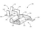
既に述べたように、本発明は、コネクタハウジングに挿入されているポジティブロックレセプタクルを確実に保持するための複数のクラッシュリブを含む、絶縁されているコネクタハウジングを提供する。図を参照すると、図1及び図2は、本発明のコネクタハウジングと一緒に使用するための例示的なポジティブロック端子又はレセプタクルの図を提供している。図1〜図2に示すように、例示的なポジティブロック端子/レセプタクル100は、絶縁バレル102とハウジング挿入部分104とを含む。絶縁バレル102は、第1のキャリアストリップ110と、絶縁クリンプ112と、ワイヤバレルクリンプ114と、人間工学に基づいた保持壁116と、第2のキャリアストリップ118と、を更に含む。ハウジング挿入部分104は、第1の電気コンタクトロール120と、第2の電気コンタクトロール122と、ロック陥凹部124と、解放ラッチ126と、を含む。 As already mentioned, the present invention provides an insulated connector housing that includes a plurality of crash ribs for securely holding a positive lock receptacle inserted into the connector housing. Referring to the figures, FIGS. 1 and 2 provide an illustration of an exemplary positive lock terminal or receptacle for use with the connector housing of the present invention. As shown in FIGS. 1-2, an exemplary positive lock terminal /
図3〜図6は本発明の例示的な実施形態に係るクラッシュリブコネクタハウジング200の図を提供しており、それらにおいては、クラッシュリブコネクタハウジング200は、ポジティブロックレセプタクル100を受け入れ、ポジティブロックレセプタクル100を確実に保持するように適合されている。図3〜図6に示すように、コネクタハウジング200は、他のコネクタと接合又は嵌合するための嵌合端部202と、ポジティブロックレセプタクル100のハウジング挿入部分104を受け入れるためのレセプタクル挿入端部(ワイヤ出口)204と、を含む。コネクタハウジング200は、絶縁ハウジング本体210(その材料により、コネクタハウジング200は電気絶縁特性を得る)と、保持タブ212と、第1のクラッシュリブ214と、第2のクラッシュリブ216と、ポジティブロックカム(CAM)218と、第1のコンタクト停止部220と、第2のコンタクト停止部222と、第3のコンタクト停止部224と、を更に含み、これらは全て、ハウジング挿入部分104をコネクタハウジング200内に適正に配置する役割を果たす。
図7に示すように、保護キャップ300は、本体302と、そこに形成されている複数の保持アーム304と、を含み、保持アーム304は、絶縁ハウジング本体210に形成されている複数の保持タブ212と協働して、キャップ300をコネクタハウジング200に接続し、ポジティブロックレセプタクル100を囲い込む。3-6 provide views of a crush
As shown in FIG. 7, the
適切に組み付けると、電気ワイヤはポジティブロックレセプタクル100で終端され、ポジティブロックレセプタクル100は次いで、図7に示すようにコネクタハウジングに挿入される。十分な力をかけると、第1の電気コンタクトロール120及び第2の電気コンタクトロール122は、第1のクラッシュリブ214及び第2のクラッシュリブ216にそれぞれ係合する。挿入工程の間、第1及び第2のクラッシュリブ214及び216は変形し、このことにより、コンタクトロールに対して大きな応力を生じさせることなく、電気コンタクトロール120及び122とコネクタハウジング200との間の緊密かつ確実な嵌合が保証される。キャップ300は次いでコネクタハウジング200に取り付けられ、この結果、完全なレセプタクルコネクタが形成される。 When properly assembled, the electrical wire is terminated with a
本発明をその例示的な実施形態の説明によって例示してきたが、及び、それらの実施形態をある程度詳細に説明してきたが、付属の特許請求の範囲をそのような詳細に制限する又は何らかの形で限定する意図は、全くない。当業者には、追加の利点及び修正が容易に明らかになるであろう。したがって、その広い解釈における本発明は、図示され説明されている特定の詳細、代表的なデバイス及び方法、並びに/又は説明用の例の、いずれにも限定されない。したがって、全体的な新規な概念の趣旨又は範囲から逸脱することなく、そのような詳細からの変更を行うことができる。 Although the invention has been illustrated by way of illustration of example embodiments thereof, and those embodiments have been described in some detail, the appended claims are limited to such details or in any way. There is no intent to limit. Additional advantages and modifications will be readily apparent to those skilled in the art. Accordingly, the invention in its broad interpretation is not limited to any particular details shown, described, representative devices and methods, and / or illustrative examples. Accordingly, changes from such details may be made without departing from the spirit or scope of the overall novel concept.
Claims (8)
Translated fromJapanese(a)ポジティブロックレセプタクル(100)と
(b)前記ポジティブロックレセプタクル(100)を受け入れるように適合されたハウジング(200)とを含み、
前記ポジティブロックレセプタクル(100)は、
(i)ワイヤ受け入れ部分(102、112、114)、並びに
(ii)第1の電気コンタクトロール(120)及び第2の電気コンタクトロール(122)を含む、ハウジング挿入部分(104)を含み、
前記ハウジング(200)は、
(i)絶縁ハウジング本体(210)、並びに
(ii)前記絶縁ハウジング本体(210)内に配置されている第1のクラッシュリブ(214)及び前記絶縁ハウジング本体(210)内に配置されている第2のクラッシュリブ(216)を含み、
(iii)前記第1のクラッシュリブ(214)及び前記第2のクラッシュリブ(216)は、前記ポジティブロックレセプタクル(100)の前記ハウジング挿入部分(104)が前記ハウジング(200)に挿入されたとき、前記第1の電気コンタクトロール(120)及び第2の電気コンタクトロール(122)にそれぞれ係合しこれらを固定する、レセプタクルコネクタ。A receptacle connector,
(A) a positive lock receptacle (100) and (b) a housing (200) adapted to receive the positive lock receptacle (100);
The positive lock receptacle (100) is:
(I) a housing receiving portion (104) comprising a wire receiving portion (102, 112, 114), and (ii) a first electrical contact roll (120) and a second electrical contact roll (122);
The housing (200)
(I) an insulating housing body (210); and (ii) a first crush rib (214) disposed within the insulating housing body (210) and a first crush rib disposed within the insulating housing body (210). 2 crush ribs (216),
(Iii) The first crush rib (214) and the second crush rib (216) are formed when the housing insertion portion (104) of the positive lock receptacle (100) is inserted into the housing (200). A receptacle connector that engages and fixes the first electrical contact roll (120) and the second electrical contact roll (122), respectively.
Applications Claiming Priority (3)
| Application Number | Priority Date | Filing Date | Title |
|---|---|---|---|
| US15/251,592 | 2016-08-30 | ||
| US15/251,592US9692163B1 (en) | 2016-08-30 | 2016-08-30 | Crush rib housing for postive lock receptacle |
| PCT/IB2017/055090WO2018042292A1 (en) | 2016-08-30 | 2017-08-23 | Crush rib housing for positive lock receptacle |
Publications (1)
| Publication Number | Publication Date |
|---|---|
| JP2019525438Atrue JP2019525438A (en) | 2019-09-05 |
Family
ID=59069629
Family Applications (1)
| Application Number | Title | Priority Date | Filing Date |
|---|---|---|---|
| JP2019511421APendingJP2019525438A (en) | 2016-08-30 | 2017-08-23 | Crash rib housing for positive lock receptacle |
Country Status (6)
| Country | Link |
|---|---|
| US (1) | US9692163B1 (en) |
| EP (1) | EP3507868A1 (en) |
| JP (1) | JP2019525438A (en) |
| KR (1) | KR102230205B1 (en) |
| CN (2) | CN109643864A (en) |
| WO (1) | WO2018042292A1 (en) |
Families Citing this family (17)
| Publication number | Priority date | Publication date | Assignee | Title |
|---|---|---|---|---|
| US10027037B2 (en)* | 2016-07-06 | 2018-07-17 | Te Connectivity Corporation | Terminal with reduced normal force |
| US9692163B1 (en)* | 2016-08-30 | 2017-06-27 | Te Connectivity Corporation | Crush rib housing for postive lock receptacle |
| DE102016221351A1 (en)* | 2016-10-28 | 2018-05-03 | Te Connectivity Germany Gmbh | Flat contact socket with extension arm |
| US10079440B1 (en)* | 2017-05-05 | 2018-09-18 | Te Connectivity Corporation | Electrical terminal having a push surface |
| JP1604439S (en)* | 2017-11-01 | 2018-05-21 | ||
| US10193259B1 (en)* | 2017-12-22 | 2019-01-29 | Te Connectivity Corporation | Receptacle connector housing with hold-down ribs |
| CN208111733U (en)* | 2018-03-13 | 2018-11-16 | 泰科电子(上海)有限公司 | connection terminal |
| CN208209061U (en)* | 2018-03-13 | 2018-12-07 | 泰科电子(上海)有限公司 | Connection terminal |
| CN208904272U (en)* | 2018-06-01 | 2019-05-24 | 泰科电子(上海)有限公司 | Connectors and Connector Housings |
| US10855024B2 (en) | 2018-10-29 | 2020-12-01 | Te Connectivity Corporation | Electrical connector with latches and terminal position assurance projections provided on hinged cover |
| CN209561678U (en)* | 2019-02-18 | 2019-10-29 | 泰科电子(上海)有限公司 | socket terminal |
| EP3719936B1 (en) | 2019-04-02 | 2023-08-30 | TE Connectivity Italia Distribution S.r.l. | Connector device |
| CN211789804U (en)* | 2020-02-19 | 2020-10-27 | 泰科电子(上海)有限公司 | electrical connector |
| JP7104103B2 (en)* | 2020-06-26 | 2022-07-20 | 矢崎総業株式会社 | connector |
| US11381020B1 (en)* | 2021-01-25 | 2022-07-05 | TE Connectivity Services Gmbh | Electrical terminal for mating with two coplanar tabs |
| CN115133306A (en)* | 2021-03-25 | 2022-09-30 | 泰科电子(上海)有限公司 | Flag terminal |
| CN115224514A (en)* | 2021-04-14 | 2022-10-21 | 泰科电子(上海)有限公司 | Electrical connection terminal and electrical connection assembly |
Citations (7)
| Publication number | Priority date | Publication date | Assignee | Title |
|---|---|---|---|---|
| US3648213A (en)* | 1966-08-15 | 1972-03-07 | Amp Inc | Electrical housing member |
| JPS52114988A (en)* | 1976-03-17 | 1977-09-27 | Amp Inc | Housing for electric terminal |
| JPS556708A (en)* | 1978-06-30 | 1980-01-18 | Yazaki Corp | Electric connector |
| JPH07335305A (en)* | 1994-06-13 | 1995-12-22 | Whitaker Corp:The | Electrical connector and its housing |
| JPH10247540A (en)* | 1997-03-05 | 1998-09-14 | Koito Mfg Co Ltd | Electric connector |
| US8057261B1 (en)* | 2010-11-02 | 2011-11-15 | Etco, Inc. | Flag terminal insulator |
| JP2015185425A (en)* | 2014-03-25 | 2015-10-22 | アイチエレック株式会社 | Crimp connection terminal |
Family Cites Families (22)
| Publication number | Priority date | Publication date | Assignee | Title |
|---|---|---|---|---|
| US3514740A (en)* | 1968-03-04 | 1970-05-26 | John Richard Filson | Wire-end connector structure |
| US3555493A (en)* | 1968-03-25 | 1971-01-12 | Molex Products Co | Right angle printed circuit board connector |
| US3771111A (en)* | 1972-06-12 | 1973-11-06 | Amp Inc | Flag type electrical terminal |
| DE2856497C2 (en)* | 1978-12-28 | 1983-02-03 | Siemens AG, 1000 Berlin und 8000 München | Method for producing a detachable electrical plug connection |
| DE7925002U1 (en)* | 1979-09-04 | 1980-04-10 | Simon, Hans, 5463 Unkel | Isolation for flat receptacles |
| US4395081A (en)* | 1981-04-06 | 1983-07-26 | Sweda International, Inc. | Electrical connector |
| US4421375A (en)* | 1982-03-29 | 1983-12-20 | Amp Incorporated | Flag-type terminal having insulation displacement wire connection |
| US4534613A (en)* | 1983-10-31 | 1985-08-13 | Amp Incorporated | Receptacle terminal having locking lance |
| JPH0684560A (en)* | 1992-09-03 | 1994-03-25 | Sumitomo Wiring Syst Ltd | Multi-electrode connection terminal and manufactures thereof |
| TW346263U (en)* | 1997-08-16 | 1998-11-21 | Hon Hai Prec Ind Co Ltd | Connector of parallel wires |
| KR19990031545U (en)* | 1997-12-31 | 1999-07-26 | 최진호 | Power connection terminal |
| JP3601773B2 (en)* | 1999-12-08 | 2004-12-15 | 矢崎総業株式会社 | Terminal |
| DE10139797A1 (en)* | 2001-08-14 | 2003-02-27 | Bsh Bosch Siemens Hausgeraete | Electrical connector |
| US7198526B1 (en)* | 2005-11-21 | 2007-04-03 | Etco, Inc. | Low-profile flag electrical terminal connector assembly |
| DE102007044412A1 (en)* | 2007-09-18 | 2009-03-19 | Lear Corp., Southfield | Electrical connector assembly |
| JP5649969B2 (en)* | 2007-10-02 | 2015-01-07 | オスラム ゲーエムベーハーOSRAM GmbH | Plug device, plug connector, and method of manufacturing the plug device |
| FR2923090A1 (en)* | 2007-10-31 | 2009-05-01 | C & K Components Soc Par Actio | MINIATURE ELECTRICAL CONNECTOR WITH EXTRACTIBLE CONTACT ELEMENTS AND ASSOCIATED TOOL FOR UNLOCKING AND EXTRACTING CONTACTS |
| CN201285861Y (en)* | 2008-09-09 | 2009-08-05 | 富士康(昆山)电脑接插件有限公司 | Electric connector |
| CN102347569A (en)* | 2010-07-30 | 2012-02-08 | 昆山市玉山镇群崴精密机械制造厂 | Metal casing structure for coaxial connector |
| CN104412140B (en)* | 2012-06-12 | 2017-09-12 | 富加宜(亚洲)私人有限公司 | Connector including locking device |
| JP6279852B2 (en)* | 2013-07-19 | 2018-02-14 | 日本圧着端子製造株式会社 | Electrical connector housing and electrical connector |
| US9692163B1 (en)* | 2016-08-30 | 2017-06-27 | Te Connectivity Corporation | Crush rib housing for postive lock receptacle |
- 2016
- 2016-08-30USUS15/251,592patent/US9692163B1/enactiveActive
- 2017
- 2017-08-23JPJP2019511421Apatent/JP2019525438A/enactivePending
- 2017-08-23CNCN201780052382.4Apatent/CN109643864A/enactivePending
- 2017-08-23CNCN202211069126.5Apatent/CN115425449A/enactivePending
- 2017-08-23WOPCT/IB2017/055090patent/WO2018042292A1/ennot_activeCeased
- 2017-08-23KRKR1020197008762Apatent/KR102230205B1/enactiveActive
- 2017-08-23EPEP17769124.3Apatent/EP3507868A1/ennot_activeWithdrawn
Patent Citations (7)
| Publication number | Priority date | Publication date | Assignee | Title |
|---|---|---|---|---|
| US3648213A (en)* | 1966-08-15 | 1972-03-07 | Amp Inc | Electrical housing member |
| JPS52114988A (en)* | 1976-03-17 | 1977-09-27 | Amp Inc | Housing for electric terminal |
| JPS556708A (en)* | 1978-06-30 | 1980-01-18 | Yazaki Corp | Electric connector |
| JPH07335305A (en)* | 1994-06-13 | 1995-12-22 | Whitaker Corp:The | Electrical connector and its housing |
| JPH10247540A (en)* | 1997-03-05 | 1998-09-14 | Koito Mfg Co Ltd | Electric connector |
| US8057261B1 (en)* | 2010-11-02 | 2011-11-15 | Etco, Inc. | Flag terminal insulator |
| JP2015185425A (en)* | 2014-03-25 | 2015-10-22 | アイチエレック株式会社 | Crimp connection terminal |
Also Published As
| Publication number | Publication date |
|---|---|
| CN115425449A (en) | 2022-12-02 |
| WO2018042292A1 (en) | 2018-03-08 |
| KR102230205B1 (en) | 2021-03-23 |
| US9692163B1 (en) | 2017-06-27 |
| CN109643864A (en) | 2019-04-16 |
| KR20190039326A (en) | 2019-04-10 |
| EP3507868A1 (en) | 2019-07-10 |
Similar Documents
| Publication | Publication Date | Title |
|---|---|---|
| JP2019525438A (en) | Crash rib housing for positive lock receptacle | |
| TWI358863B (en) | ||
| US8096828B2 (en) | Electrical connector for terminating a coaxial cable | |
| WO2012127541A1 (en) | Wire-to-board connector | |
| US20080070446A1 (en) | Tool extractable contacts for electrical connectors | |
| TWI624115B (en) | Socket electrical connector, plug electrical connector and combinations thereof | |
| JPS59196587A (en) | Electric connector | |
| US20130017714A1 (en) | Flat plug electrical connector | |
| JP2010049896A (en) | Connector | |
| WO2014175176A1 (en) | Connector | |
| JP2004281207A (en) | connector | |
| US7604518B2 (en) | Electrical contact with retention latch | |
| KR101680273B1 (en) | Plug terminal for connector | |
| EP3540868B1 (en) | Locking electrical receptacle | |
| US9203225B2 (en) | Wire fixing member | |
| CN110391532B (en) | Connector | |
| JPS645757B2 (en) | ||
| US20190288428A1 (en) | Connection Terminal | |
| JP2017068918A (en) | Branch connector | |
| JP2015173136A (en) | connector | |
| US2691145A (en) | Snap latch plug | |
| KR101758673B1 (en) | Connector assembly | |
| JPH04102167U (en) | contact | |
| JP4446477B2 (en) | connector | |
| JP6131110B2 (en) | Female terminals and connectors |
Legal Events
| Date | Code | Title | Description |
|---|---|---|---|
| A621 | Written request for application examination | Free format text:JAPANESE INTERMEDIATE CODE: A621 Effective date:20190402 | |
| A977 | Report on retrieval | Free format text:JAPANESE INTERMEDIATE CODE: A971007 Effective date:20200323 | |
| A131 | Notification of reasons for refusal | Free format text:JAPANESE INTERMEDIATE CODE: A131 Effective date:20200331 | |
| A02 | Decision of refusal | Free format text:JAPANESE INTERMEDIATE CODE: A02 Effective date:20201020 |