JP2019521872A - Dynamic compensation of a robot arm mounted on a flexible arm - Google Patents
Dynamic compensation of a robot arm mounted on a flexible armDownload PDFInfo
- Publication number
- JP2019521872A JP2019521872AJP2019523148AJP2019523148AJP2019521872AJP 2019521872 AJP2019521872 AJP 2019521872AJP 2019523148 AJP2019523148 AJP 2019523148AJP 2019523148 AJP2019523148 AJP 2019523148AJP 2019521872 AJP2019521872 AJP 2019521872A
- Authority
- JP
- Japan
- Prior art keywords
- boom
- base
- target
- control system
- robot
- Prior art date
- Legal status (The legal status is an assumption and is not a legal conclusion. Google has not performed a legal analysis and makes no representation as to the accuracy of the status listed.)
- Granted
Links
Images


Classifications
- G—PHYSICS
- G05—CONTROLLING; REGULATING
- G05B—CONTROL OR REGULATING SYSTEMS IN GENERAL; FUNCTIONAL ELEMENTS OF SUCH SYSTEMS; MONITORING OR TESTING ARRANGEMENTS FOR SUCH SYSTEMS OR ELEMENTS
- G05B19/00—Programme-control systems
- G05B19/02—Programme-control systems electric
- G05B19/18—Numerical control [NC], i.e. automatically operating machines, in particular machine tools, e.g. in a manufacturing environment, so as to execute positioning, movement or co-ordinated operations by means of programme data in numerical form
- G05B19/4097—Numerical control [NC], i.e. automatically operating machines, in particular machine tools, e.g. in a manufacturing environment, so as to execute positioning, movement or co-ordinated operations by means of programme data in numerical form characterised by using design data to control NC machines, e.g. CAD/CAM
- B—PERFORMING OPERATIONS; TRANSPORTING
- B25—HAND TOOLS; PORTABLE POWER-DRIVEN TOOLS; MANIPULATORS
- B25J—MANIPULATORS; CHAMBERS PROVIDED WITH MANIPULATION DEVICES
- B25J13/00—Controls for manipulators
- B25J13/08—Controls for manipulators by means of sensing devices, e.g. viewing or touching devices
- B25J13/088—Controls for manipulators by means of sensing devices, e.g. viewing or touching devices with position, velocity or acceleration sensors
- B25J13/089—Determining the position of the robot with reference to its environment
- B—PERFORMING OPERATIONS; TRANSPORTING
- B25—HAND TOOLS; PORTABLE POWER-DRIVEN TOOLS; MANIPULATORS
- B25J—MANIPULATORS; CHAMBERS PROVIDED WITH MANIPULATION DEVICES
- B25J19/00—Accessories fitted to manipulators, e.g. for monitoring, for viewing; Safety devices combined with or specially adapted for use in connection with manipulators
- B25J19/02—Sensing devices
- B25J19/021—Optical sensing devices
- B25J19/022—Optical sensing devices using lasers
- B—PERFORMING OPERATIONS; TRANSPORTING
- B25—HAND TOOLS; PORTABLE POWER-DRIVEN TOOLS; MANIPULATORS
- B25J—MANIPULATORS; CHAMBERS PROVIDED WITH MANIPULATION DEVICES
- B25J5/00—Manipulators mounted on wheels or on carriages
- B—PERFORMING OPERATIONS; TRANSPORTING
- B25—HAND TOOLS; PORTABLE POWER-DRIVEN TOOLS; MANIPULATORS
- B25J—MANIPULATORS; CHAMBERS PROVIDED WITH MANIPULATION DEVICES
- B25J9/00—Programme-controlled manipulators
- B25J9/02—Programme-controlled manipulators characterised by movement of the arms, e.g. cartesian coordinate type
- B25J9/023—Cartesian coordinate type
- B—PERFORMING OPERATIONS; TRANSPORTING
- B25—HAND TOOLS; PORTABLE POWER-DRIVEN TOOLS; MANIPULATORS
- B25J—MANIPULATORS; CHAMBERS PROVIDED WITH MANIPULATION DEVICES
- B25J9/00—Programme-controlled manipulators
- B25J9/16—Programme controls
- B25J9/1602—Programme controls characterised by the control system, structure, architecture
- B25J9/161—Hardware, e.g. neural networks, fuzzy logic, interfaces, processor
- B—PERFORMING OPERATIONS; TRANSPORTING
- B25—HAND TOOLS; PORTABLE POWER-DRIVEN TOOLS; MANIPULATORS
- B25J—MANIPULATORS; CHAMBERS PROVIDED WITH MANIPULATION DEVICES
- B25J9/00—Programme-controlled manipulators
- B25J9/16—Programme controls
- B25J9/1612—Programme controls characterised by the hand, wrist, grip control
- B—PERFORMING OPERATIONS; TRANSPORTING
- B25—HAND TOOLS; PORTABLE POWER-DRIVEN TOOLS; MANIPULATORS
- B25J—MANIPULATORS; CHAMBERS PROVIDED WITH MANIPULATION DEVICES
- B25J9/00—Programme-controlled manipulators
- B25J9/16—Programme controls
- B25J9/1615—Programme controls characterised by special kind of manipulator, e.g. planar, scara, gantry, cantilever, space, closed chain, passive/active joints and tendon driven manipulators
- B25J9/162—Mobile manipulator, movable base with manipulator arm mounted on it
- B—PERFORMING OPERATIONS; TRANSPORTING
- B25—HAND TOOLS; PORTABLE POWER-DRIVEN TOOLS; MANIPULATORS
- B25J—MANIPULATORS; CHAMBERS PROVIDED WITH MANIPULATION DEVICES
- B25J9/00—Programme-controlled manipulators
- B25J9/16—Programme controls
- B25J9/1628—Programme controls characterised by the control loop
- B25J9/1633—Programme controls characterised by the control loop compliant, force, torque control, e.g. combined with position control
- B—PERFORMING OPERATIONS; TRANSPORTING
- B25—HAND TOOLS; PORTABLE POWER-DRIVEN TOOLS; MANIPULATORS
- B25J—MANIPULATORS; CHAMBERS PROVIDED WITH MANIPULATION DEVICES
- B25J9/00—Programme-controlled manipulators
- B25J9/16—Programme controls
- B25J9/1628—Programme controls characterised by the control loop
- B25J9/1635—Programme controls characterised by the control loop flexible-arm control
- B—PERFORMING OPERATIONS; TRANSPORTING
- B25—HAND TOOLS; PORTABLE POWER-DRIVEN TOOLS; MANIPULATORS
- B25J—MANIPULATORS; CHAMBERS PROVIDED WITH MANIPULATION DEVICES
- B25J9/00—Programme-controlled manipulators
- B25J9/16—Programme controls
- B25J9/1628—Programme controls characterised by the control loop
- B25J9/1638—Programme controls characterised by the control loop compensation for arm bending/inertia, pay load weight/inertia
- B—PERFORMING OPERATIONS; TRANSPORTING
- B25—HAND TOOLS; PORTABLE POWER-DRIVEN TOOLS; MANIPULATORS
- B25J—MANIPULATORS; CHAMBERS PROVIDED WITH MANIPULATION DEVICES
- B25J9/00—Programme-controlled manipulators
- B25J9/16—Programme controls
- B25J9/1628—Programme controls characterised by the control loop
- B25J9/1651—Programme controls characterised by the control loop acceleration, rate control
- B—PERFORMING OPERATIONS; TRANSPORTING
- B25—HAND TOOLS; PORTABLE POWER-DRIVEN TOOLS; MANIPULATORS
- B25J—MANIPULATORS; CHAMBERS PROVIDED WITH MANIPULATION DEVICES
- B25J9/00—Programme-controlled manipulators
- B25J9/16—Programme controls
- B25J9/1656—Programme controls characterised by programming, planning systems for manipulators
- B25J9/1664—Programme controls characterised by programming, planning systems for manipulators characterised by motion, path, trajectory planning
- B—PERFORMING OPERATIONS; TRANSPORTING
- B25—HAND TOOLS; PORTABLE POWER-DRIVEN TOOLS; MANIPULATORS
- B25J—MANIPULATORS; CHAMBERS PROVIDED WITH MANIPULATION DEVICES
- B25J9/00—Programme-controlled manipulators
- B25J9/16—Programme controls
- B25J9/1674—Programme controls characterised by safety, monitoring, diagnostic
- B—PERFORMING OPERATIONS; TRANSPORTING
- B25—HAND TOOLS; PORTABLE POWER-DRIVEN TOOLS; MANIPULATORS
- B25J—MANIPULATORS; CHAMBERS PROVIDED WITH MANIPULATION DEVICES
- B25J9/00—Programme-controlled manipulators
- B25J9/16—Programme controls
- B25J9/1679—Programme controls characterised by the tasks executed
- B25J9/1684—Tracking a line or surface by means of sensors
- B—PERFORMING OPERATIONS; TRANSPORTING
- B25—HAND TOOLS; PORTABLE POWER-DRIVEN TOOLS; MANIPULATORS
- B25J—MANIPULATORS; CHAMBERS PROVIDED WITH MANIPULATION DEVICES
- B25J9/00—Programme-controlled manipulators
- B25J9/16—Programme controls
- B25J9/1694—Programme controls characterised by use of sensors other than normal servo-feedback from position, speed or acceleration sensors, perception control, multi-sensor controlled systems, sensor fusion
- B—PERFORMING OPERATIONS; TRANSPORTING
- B28—WORKING CEMENT, CLAY, OR STONE
- B28D—WORKING STONE OR STONE-LIKE MATERIALS
- B28D1/00—Working stone or stone-like materials, e.g. brick, concrete or glass, not provided for elsewhere; Machines, devices, tools therefor
- B28D1/003—Multipurpose machines; Equipment therefor
- B—PERFORMING OPERATIONS; TRANSPORTING
- B28—WORKING CEMENT, CLAY, OR STONE
- B28D—WORKING STONE OR STONE-LIKE MATERIALS
- B28D1/00—Working stone or stone-like materials, e.g. brick, concrete or glass, not provided for elsewhere; Machines, devices, tools therefor
- B28D1/02—Working stone or stone-like materials, e.g. brick, concrete or glass, not provided for elsewhere; Machines, devices, tools therefor by sawing
- B28D1/10—Working stone or stone-like materials, e.g. brick, concrete or glass, not provided for elsewhere; Machines, devices, tools therefor by sawing with provision for measuring
- B—PERFORMING OPERATIONS; TRANSPORTING
- B28—WORKING CEMENT, CLAY, OR STONE
- B28D—WORKING STONE OR STONE-LIKE MATERIALS
- B28D1/00—Working stone or stone-like materials, e.g. brick, concrete or glass, not provided for elsewhere; Machines, devices, tools therefor
- B28D1/18—Working stone or stone-like materials, e.g. brick, concrete or glass, not provided for elsewhere; Machines, devices, tools therefor by milling, e.g. channelling by means of milling tools
- B28D1/186—Tools therefor, e.g. having exchangeable cutter bits
- B—PERFORMING OPERATIONS; TRANSPORTING
- B28—WORKING CEMENT, CLAY, OR STONE
- B28D—WORKING STONE OR STONE-LIKE MATERIALS
- B28D7/00—Accessories specially adapted for use with machines or devices of the preceding groups
- B28D7/005—Devices for the automatic drive or the program control of the machines
- B—PERFORMING OPERATIONS; TRANSPORTING
- B28—WORKING CEMENT, CLAY, OR STONE
- B28D—WORKING STONE OR STONE-LIKE MATERIALS
- B28D7/00—Accessories specially adapted for use with machines or devices of the preceding groups
- B28D7/04—Accessories specially adapted for use with machines or devices of the preceding groups for supporting or holding work or conveying or discharging work
- B—PERFORMING OPERATIONS; TRANSPORTING
- B60—VEHICLES IN GENERAL
- B60P—VEHICLES ADAPTED FOR LOAD TRANSPORTATION OR TO TRANSPORT, TO CARRY, OR TO COMPRISE SPECIAL LOADS OR OBJECTS
- B60P1/00—Vehicles predominantly for transporting loads and modified to facilitate loading, consolidating the load, or unloading
- B60P1/48—Vehicles predominantly for transporting loads and modified to facilitate loading, consolidating the load, or unloading using pivoted arms raisable above load-transporting element
- E—FIXED CONSTRUCTIONS
- E04—BUILDING
- E04B—GENERAL BUILDING CONSTRUCTIONS; WALLS, e.g. PARTITIONS; ROOFS; FLOORS; CEILINGS; INSULATION OR OTHER PROTECTION OF BUILDINGS
- E04B1/00—Constructions in general; Structures which are not restricted either to walls, e.g. partitions, or floors or ceilings or roofs
- E04B1/02—Structures consisting primarily of load-supporting, block-shaped, or slab-shaped elements
- E—FIXED CONSTRUCTIONS
- E04—BUILDING
- E04G—SCAFFOLDING; FORMS; SHUTTERING; BUILDING IMPLEMENTS OR AIDS, OR THEIR USE; HANDLING BUILDING MATERIALS ON THE SITE; REPAIRING, BREAKING-UP OR OTHER WORK ON EXISTING BUILDINGS
- E04G21/00—Preparing, conveying, or working-up building materials or building elements in situ; Other devices or measures for constructional work
- E04G21/14—Conveying or assembling building elements
- E04G21/16—Tools or apparatus
- E04G21/22—Tools or apparatus for setting building elements with mortar, e.g. bricklaying machines
- G—PHYSICS
- G05—CONTROLLING; REGULATING
- G05B—CONTROL OR REGULATING SYSTEMS IN GENERAL; FUNCTIONAL ELEMENTS OF SUCH SYSTEMS; MONITORING OR TESTING ARRANGEMENTS FOR SUCH SYSTEMS OR ELEMENTS
- G05B19/00—Programme-control systems
- G05B19/02—Programme-control systems electric
- G05B19/18—Numerical control [NC], i.e. automatically operating machines, in particular machine tools, e.g. in a manufacturing environment, so as to execute positioning, movement or co-ordinated operations by means of programme data in numerical form
- G05B19/416—Numerical control [NC], i.e. automatically operating machines, in particular machine tools, e.g. in a manufacturing environment, so as to execute positioning, movement or co-ordinated operations by means of programme data in numerical form characterised by control of velocity, acceleration or deceleration
- G—PHYSICS
- G05—CONTROLLING; REGULATING
- G05B—CONTROL OR REGULATING SYSTEMS IN GENERAL; FUNCTIONAL ELEMENTS OF SUCH SYSTEMS; MONITORING OR TESTING ARRANGEMENTS FOR SUCH SYSTEMS OR ELEMENTS
- G05B19/00—Programme-control systems
- G05B19/02—Programme-control systems electric
- G05B19/418—Total factory control, i.e. centrally controlling a plurality of machines, e.g. direct or distributed numerical control [DNC], flexible manufacturing systems [FMS], integrated manufacturing systems [IMS] or computer integrated manufacturing [CIM]
- G05B19/41815—Total factory control, i.e. centrally controlling a plurality of machines, e.g. direct or distributed numerical control [DNC], flexible manufacturing systems [FMS], integrated manufacturing systems [IMS] or computer integrated manufacturing [CIM] characterised by the cooperation between machine tools, manipulators and conveyor or other workpiece supply system, workcell
- G05B19/4182—Total factory control, i.e. centrally controlling a plurality of machines, e.g. direct or distributed numerical control [DNC], flexible manufacturing systems [FMS], integrated manufacturing systems [IMS] or computer integrated manufacturing [CIM] characterised by the cooperation between machine tools, manipulators and conveyor or other workpiece supply system, workcell manipulators and conveyor only
- G—PHYSICS
- G06—COMPUTING OR CALCULATING; COUNTING
- G06F—ELECTRIC DIGITAL DATA PROCESSING
- G06F16/00—Information retrieval; Database structures therefor; File system structures therefor
- G—PHYSICS
- G06—COMPUTING OR CALCULATING; COUNTING
- G06F—ELECTRIC DIGITAL DATA PROCESSING
- G06F16/00—Information retrieval; Database structures therefor; File system structures therefor
- G06F16/10—File systems; File servers
- G06F16/17—Details of further file system functions
- G06F16/1734—Details of monitoring file system events, e.g. by the use of hooks, filter drivers, logs
- G—PHYSICS
- G06—COMPUTING OR CALCULATING; COUNTING
- G06F—ELECTRIC DIGITAL DATA PROCESSING
- G06F30/00—Computer-aided design [CAD]
- G06F30/10—Geometric CAD
- G06F30/13—Architectural design, e.g. computer-aided architectural design [CAAD] related to design of buildings, bridges, landscapes, production plants or roads
- H—ELECTRICITY
- H04—ELECTRIC COMMUNICATION TECHNIQUE
- H04W—WIRELESS COMMUNICATION NETWORKS
- H04W4/00—Services specially adapted for wireless communication networks; Facilities therefor
- H04W4/70—Services for machine-to-machine communication [M2M] or machine type communication [MTC]
- B—PERFORMING OPERATIONS; TRANSPORTING
- B25—HAND TOOLS; PORTABLE POWER-DRIVEN TOOLS; MANIPULATORS
- B25J—MANIPULATORS; CHAMBERS PROVIDED WITH MANIPULATION DEVICES
- B25J9/00—Programme-controlled manipulators
- B25J9/16—Programme controls
- B25J9/1694—Programme controls characterised by use of sensors other than normal servo-feedback from position, speed or acceleration sensors, perception control, multi-sensor controlled systems, sensor fusion
- B25J9/1697—Vision controlled systems
- B—PERFORMING OPERATIONS; TRANSPORTING
- B60—VEHICLES IN GENERAL
- B60P—VEHICLES ADAPTED FOR LOAD TRANSPORTATION OR TO TRANSPORT, TO CARRY, OR TO COMPRISE SPECIAL LOADS OR OBJECTS
- B60P3/00—Vehicles adapted to transport, to carry or to comprise special loads or objects
- B60P3/28—Vehicles adapted to transport, to carry or to comprise special loads or objects for transporting cranes
- B—PERFORMING OPERATIONS; TRANSPORTING
- B66—HOISTING; LIFTING; HAULING
- B66C—CRANES; LOAD-ENGAGING ELEMENTS OR DEVICES FOR CRANES, CAPSTANS, WINCHES, OR TACKLES
- B66C13/00—Other constructional features or details
- B66C13/18—Control systems or devices
- B66C13/22—Control systems or devices for electric drives
- E—FIXED CONSTRUCTIONS
- E04—BUILDING
- E04B—GENERAL BUILDING CONSTRUCTIONS; WALLS, e.g. PARTITIONS; ROOFS; FLOORS; CEILINGS; INSULATION OR OTHER PROTECTION OF BUILDINGS
- E04B2/00—Walls, e.g. partitions, for buildings; Wall construction with regard to insulation; Connections specially adapted to walls
- E04B2/02—Walls, e.g. partitions, for buildings; Wall construction with regard to insulation; Connections specially adapted to walls built-up from layers of building elements
- E04B2/04—Walls having neither cavities between, nor in, the solid elements
- E—FIXED CONSTRUCTIONS
- E04—BUILDING
- E04F—FINISHING WORK ON BUILDINGS, e.g. STAIRS, FLOORS
- E04F21/00—Implements for finishing work on buildings
- E04F21/02—Implements for finishing work on buildings for applying plasticised masses to surfaces, e.g. plastering walls
- E04F21/023—Implements for finishing work on buildings for applying plasticised masses to surfaces, e.g. plastering walls for applying adhesive, e.g. glue or mortar, on the covering elements, in particular tiles
- G—PHYSICS
- G01—MEASURING; TESTING
- G01C—MEASURING DISTANCES, LEVELS OR BEARINGS; SURVEYING; NAVIGATION; GYROSCOPIC INSTRUMENTS; PHOTOGRAMMETRY OR VIDEOGRAMMETRY
- G01C15/00—Surveying instruments or accessories not provided for in groups G01C1/00 - G01C13/00
- G01C15/002—Active optical surveying means
- G—PHYSICS
- G01—MEASURING; TESTING
- G01S—RADIO DIRECTION-FINDING; RADIO NAVIGATION; DETERMINING DISTANCE OR VELOCITY BY USE OF RADIO WAVES; LOCATING OR PRESENCE-DETECTING BY USE OF THE REFLECTION OR RERADIATION OF RADIO WAVES; ANALOGOUS ARRANGEMENTS USING OTHER WAVES
- G01S17/00—Systems using the reflection or reradiation of electromagnetic waves other than radio waves, e.g. lidar systems
- G01S17/66—Tracking systems using electromagnetic waves other than radio waves
- G—PHYSICS
- G05—CONTROLLING; REGULATING
- G05B—CONTROL OR REGULATING SYSTEMS IN GENERAL; FUNCTIONAL ELEMENTS OF SUCH SYSTEMS; MONITORING OR TESTING ARRANGEMENTS FOR SUCH SYSTEMS OR ELEMENTS
- G05B2219/00—Program-control systems
- G05B2219/30—Nc systems
- G05B2219/35—Nc in input of data, input till input file format
- G05B2219/35207—Design agent selects planning agent, which selects fabrication agent
- G—PHYSICS
- G05—CONTROLLING; REGULATING
- G05B—CONTROL OR REGULATING SYSTEMS IN GENERAL; FUNCTIONAL ELEMENTS OF SUCH SYSTEMS; MONITORING OR TESTING ARRANGEMENTS FOR SUCH SYSTEMS OR ELEMENTS
- G05B2219/00—Program-control systems
- G05B2219/30—Nc systems
- G05B2219/39—Robotics, robotics to robotics hand
- G05B2219/39001—Robot, manipulator control
- G—PHYSICS
- G05—CONTROLLING; REGULATING
- G05B—CONTROL OR REGULATING SYSTEMS IN GENERAL; FUNCTIONAL ELEMENTS OF SUCH SYSTEMS; MONITORING OR TESTING ARRANGEMENTS FOR SUCH SYSTEMS OR ELEMENTS
- G05B2219/00—Program-control systems
- G05B2219/30—Nc systems
- G05B2219/39—Robotics, robotics to robotics hand
- G05B2219/39172—Vehicle, coordination between manipulator arm and its moving vehicle
- G—PHYSICS
- G05—CONTROLLING; REGULATING
- G05B—CONTROL OR REGULATING SYSTEMS IN GENERAL; FUNCTIONAL ELEMENTS OF SUCH SYSTEMS; MONITORING OR TESTING ARRANGEMENTS FOR SUCH SYSTEMS OR ELEMENTS
- G05B2219/00—Program-control systems
- G05B2219/30—Nc systems
- G05B2219/40—Robotics, robotics mapping to robotics vision
- G05B2219/40257—Flexible macro manipulator with rigid attached micromanipulator
- G—PHYSICS
- G05—CONTROLLING; REGULATING
- G05B—CONTROL OR REGULATING SYSTEMS IN GENERAL; FUNCTIONAL ELEMENTS OF SUCH SYSTEMS; MONITORING OR TESTING ARRANGEMENTS FOR SUCH SYSTEMS OR ELEMENTS
- G05B2219/00—Program-control systems
- G05B2219/30—Nc systems
- G05B2219/40—Robotics, robotics mapping to robotics vision
- G05B2219/40298—Manipulator on vehicle, wheels, mobile
- G—PHYSICS
- G05—CONTROLLING; REGULATING
- G05B—CONTROL OR REGULATING SYSTEMS IN GENERAL; FUNCTIONAL ELEMENTS OF SUCH SYSTEMS; MONITORING OR TESTING ARRANGEMENTS FOR SUCH SYSTEMS OR ELEMENTS
- G05B2219/00—Program-control systems
- G05B2219/30—Nc systems
- G05B2219/40—Robotics, robotics mapping to robotics vision
- G05B2219/40513—Planning of vehicle and of its manipulator arm
- G—PHYSICS
- G05—CONTROLLING; REGULATING
- G05B—CONTROL OR REGULATING SYSTEMS IN GENERAL; FUNCTIONAL ELEMENTS OF SUCH SYSTEMS; MONITORING OR TESTING ARRANGEMENTS FOR SUCH SYSTEMS OR ELEMENTS
- G05B2219/00—Program-control systems
- G05B2219/30—Nc systems
- G05B2219/45—Nc applications
- G05B2219/45086—Brick laying, masonry robot
- G—PHYSICS
- G06—COMPUTING OR CALCULATING; COUNTING
- G06F—ELECTRIC DIGITAL DATA PROCESSING
- G06F2111/00—Details relating to CAD techniques
- G06F2111/20—Configuration CAD, e.g. designing by assembling or positioning modules selected from libraries of predesigned modules
- Y—GENERAL TAGGING OF NEW TECHNOLOGICAL DEVELOPMENTS; GENERAL TAGGING OF CROSS-SECTIONAL TECHNOLOGIES SPANNING OVER SEVERAL SECTIONS OF THE IPC; TECHNICAL SUBJECTS COVERED BY FORMER USPC CROSS-REFERENCE ART COLLECTIONS [XRACs] AND DIGESTS
- Y02—TECHNOLOGIES OR APPLICATIONS FOR MITIGATION OR ADAPTATION AGAINST CLIMATE CHANGE
- Y02B—CLIMATE CHANGE MITIGATION TECHNOLOGIES RELATED TO BUILDINGS, e.g. HOUSING, HOUSE APPLIANCES OR RELATED END-USER APPLICATIONS
- Y02B10/00—Integration of renewable energy sources in buildings
- Y02B10/30—Wind power
- Y—GENERAL TAGGING OF NEW TECHNOLOGICAL DEVELOPMENTS; GENERAL TAGGING OF CROSS-SECTIONAL TECHNOLOGIES SPANNING OVER SEVERAL SECTIONS OF THE IPC; TECHNICAL SUBJECTS COVERED BY FORMER USPC CROSS-REFERENCE ART COLLECTIONS [XRACs] AND DIGESTS
- Y02—TECHNOLOGIES OR APPLICATIONS FOR MITIGATION OR ADAPTATION AGAINST CLIMATE CHANGE
- Y02P—CLIMATE CHANGE MITIGATION TECHNOLOGIES IN THE PRODUCTION OR PROCESSING OF GOODS
- Y02P90/00—Enabling technologies with a potential contribution to greenhouse gas [GHG] emissions mitigation
- Y02P90/02—Total factory control, e.g. smart factories, flexible manufacturing systems [FMS] or integrated manufacturing systems [IMS]
Landscapes
- Engineering & Computer Science (AREA)
- Mechanical Engineering (AREA)
- Robotics (AREA)
- Physics & Mathematics (AREA)
- Architecture (AREA)
- General Physics & Mathematics (AREA)
- Theoretical Computer Science (AREA)
- Automation & Control Theory (AREA)
- General Engineering & Computer Science (AREA)
- Geometry (AREA)
- Structural Engineering (AREA)
- Civil Engineering (AREA)
- Manufacturing & Machinery (AREA)
- Human Computer Interaction (AREA)
- Computer Hardware Design (AREA)
- Mining & Mineral Resources (AREA)
- General Health & Medical Sciences (AREA)
- Health & Medical Sciences (AREA)
- Orthopedic Medicine & Surgery (AREA)
- Data Mining & Analysis (AREA)
- Databases & Information Systems (AREA)
- Evolutionary Computation (AREA)
- Pure & Applied Mathematics (AREA)
- Mathematical Optimization (AREA)
- Mathematical Analysis (AREA)
- Computational Mathematics (AREA)
- Quality & Reliability (AREA)
- Artificial Intelligence (AREA)
- Transportation (AREA)
- Fuzzy Systems (AREA)
- Mathematical Physics (AREA)
- Software Systems (AREA)
- Optics & Photonics (AREA)
- Electromagnetism (AREA)
- Computer Networks & Wireless Communication (AREA)
- Signal Processing (AREA)
- Manipulator (AREA)
- Conveying And Assembling Of Building Elements In Situ (AREA)
- Numerical Control (AREA)
- Processing Of Stones Or Stones Resemblance Materials (AREA)
Abstract
Translated fromJapaneseDescription
Translated fromJapanese本発明は、可撓性アーム上の末端効果器の制御に関し、厳密には、ブームの様な可撓性アーム上の末端効果器の位置の改善された制御に関する。本発明は、ロボットが広大な区域に亘って作業し高い精密度を必要とする、特定の用途を有している。 The present invention relates to the control of end effectors on flexible arms, and more specifically to improved control of the position of end effectors on a flexible arm such as a boom. The present invention has particular application where a robot works over a vast area and requires high precision.
次に続く背景の論考は、本発明の理解を促すことのみを目的としている。当該論考は、言及されている資料の何れかが、出願の優先日における、共通の一般知識の一部であったことを同意するものでもなく、自白するものでもない、ことを理解されたい。 The following background discussion is intended only to facilitate an understanding of the present invention. It should be understood that this discussion does not agree or confess that any of the documents mentioned were part of common general knowledge at the priority date of the application.
以下の定義は、本特許明細書全体を通じて使用される用語に適用される。ロボットアームとは、プログラム可能な機械式マニピュレータである。本明細書では、ロボットアームは、多軸関節アーム、平行運動学的ロボット(例えばスチュアートプラットフォームやデルタロボットなど)、球体幾何学形状ロボット、直交座標ロボット(直線的な動きの直交軸ロボット)など、を含む。 The following definitions apply to terms used throughout this patent specification. A robot arm is a programmable mechanical manipulator. In this specification, the robot arm is a multi-axis joint arm, a parallel kinematic robot (such as a Stuart platform or a delta robot), a spherical geometry robot, an orthogonal coordinate robot (a linear motion orthogonal axis robot), etc. including.
ブームとは、旋回ブームの様な細長い支持体構造であり、スティック又はディッパーの有無を問わず、伸縮自在要素、伸縮式ブーム、伸縮式多関節ブームの有無を問わない。例としては、クレーンブーム、アースムーバーブーム、トラッククレーンムーブが挙げられ、何れもケーブルに支持された要素又はケーブルブレースされた要素の有無を問わない。ブームは、更に、高架式ガントリー構造、若しくは片持ち式ガントリー、又は制御型引張トラス(ブームは、ブームではなく複数ケーブルに支持された平行運動学的クレーンであることもある(PARシステムズ社、引張トラス―チェルノブイリクレーン参照))を含む場合もあり、又は空間内の位置を移動する他の可動式アームを含む場合もある。 The boom is an elongated support structure such as a swivel boom, regardless of the presence or absence of a stick or dipper, regardless of the presence or absence of a telescopic element, a telescopic boom, or a telescopic articulated boom. Examples include a crane boom, an earth mover boom, and a truck crane move, each with or without an element supported by a cable or an element braided by a cable. The boom may also be an elevated gantry structure, or a cantilever gantry, or a controlled tension truss (the boom may be a parallel kinematic crane supported by multiple cables rather than a boom (PAR Systems, May include a truss-Chernobyl crane))) or may include other movable arms that move in space.
末端効果器は、環境と相互作用するように設計された、ロボットアームの端部のデバイスである。末端効果器は、グリッパ、ノズル、サンドブラスタ、スプレイガン、レンチ、磁石、溶接トーチ、切断トーチ、鋸、フライス、ルータカッター、油圧シャーなど、を含み得る。 An end effector is a device at the end of a robot arm that is designed to interact with the environment. End effectors may include grippers, nozzles, sandblasters, spray guns, wrenches, magnets, welding torches, cutting torches, saws, milling cutters, router cutters, hydraulic shears, and the like.
TCPとは工具中心点(tool center point)の略記である。これは、末端効果器又は工具上の場所であって、その位置及びその向きが制御される物体の座標を定義する。それは、通常、運動学的連鎖の遠位端に位置する。運動学的連鎖とは、ロボットアームの基部と末端効果器との間の、リンク仕掛け及びそれらの関節の連鎖をいう。 TCP is an abbreviation for tool center point. This is the location on the end effector or tool that defines the coordinates of the object whose position and orientation are controlled. It is usually located at the distal end of the kinematic chain. Kinematic chain refers to the linkage between the base of the robot arm and the end effector and the chain of their joints.
CNCは、コンピュータ/プロセッサ/マイクロコントローラに実行させる事前にプログラムされた一連の機械制御コマンドによる、機械の自動化のために使用される、コンピュータ数値制御(computer numerical control)の略記である。 CNC is an abbreviation for computer numerical control used for machine automation through a series of pre-programmed machine control commands that are executed by a computer / processor / microcontroller.
CNC制御システム内の座標変換の適用は、通常、便利な座標系でのプログラミングを許容するように遂行されている。それは、更に、CNCマシニングセンターで万力又は固定具に締め付けられるときの、加工品の位置の誤差の補正を許容するように遂行されている。 The application of coordinate transformation within a CNC control system is usually accomplished to allow programming in a convenient coordinate system. It is further performed to allow correction of workpiece position errors when clamped to a vise or fixture at a CNC machining center.
これらの座標変換は、通常、静的座標シフトを勘案する又は静的誤差を補正する、静的な意味合いで適用されている。 These coordinate transformations are usually applied in a static sense, taking static coordinate shifts into account or correcting static errors.
ロボット及びCNC機械は、便利な直交座標系でプログラムされており、直交座標をロボット又はCNC機械の姿勢を動かす関節位置へ変換するために、運動学的変換が使用される。 Robots and CNC machines are programmed with a convenient Cartesian coordinate system, and kinematic transformations are used to transform the Cartesian coordinates into joint positions that move the posture of the robot or CNC machine.
TCPに近いロボットアームの末端効果器の位置をリアルタイムで測定することがロボットの精度を高める。これは、探索及び穿孔のために使用されるロボット上の静的末端効果器で遂行されている。これは、プログラムされた位置へ動かし、位置測定を行い、補正ベクトルを計算し、補償ベクトルをプログラムされた位置へ加え、次いでTCPを新しい位置へ動かす、という多段階プロセスによって実現される。このプロセスは、厳格なリアルタイムで行われるわけではなく、静的なロボットアーム姿勢に依拠している。 Measuring the position of the end effector of the robot arm close to TCP in real time increases the accuracy of the robot. This is accomplished with a static end effector on the robot used for exploration and drilling. This is accomplished by a multi-step process of moving to a programmed position, taking a position measurement, calculating a correction vector, adding the compensation vector to the programmed position, and then moving the TCP to a new position. This process does not take place in strict real-time, but relies on a static robot arm pose.
国際公開第2007/076581号は、ブーム及び末端効果器を所望の場所へ又は所望の経路に沿って動かす制御システムを記載している。ブームは、地上に固定されて使用される基部上に、配置されている。基部を有するロボットアームは、ブームの端部へ固定されている。スキャナ−ターゲット測定システムは、ブームの端に配置されたターゲットの実際の位置及び向きを測定している。測定システムは、ターゲットの実際の位置及び向きを、6自由度(x軸、y軸、z軸及びピッチ、ロール、並びにヨー)で測定していて、6自由度はこれ以後「6DOF」とする。ブームの端に配置されたターゲットは、ロボットアームの基部に対して固定されている。制御システムは、次いで、ロボットアームの基部のプログラムされた位置(期待されている位置)と、実際に測定されたロボットアームの基部の位置と、の間の6DOFオフセットを計算し、次いで、末端効果器が正しい位置へ移動されるようにロボットアームの運動学的連鎖へ補正を適用している。ロボットアームは、地上に対する座標系ではなくその基部に対する座標系でプログラムされている。かくして、末端効果器のTCPをプログラムするためには、地上座標内でのそれの6DOF位置を、ブームの先端上に取り付けられたロボットアームの基部座標へ、変換することが必要であった。事実上、行われたことは、末端効果器を制御するためにいつも使用されているサブプログラムで、ロボットアームをプログラムして、ロボットアーム基部座標系に対して、同じ相対位置にレンガを積ませたのである。レンガが所望の場所に積まれるための所望場所にロボットアームが入るようにするために、ブームの先端は、要求される場所に入るようにプログラムされていた。 WO 2007/076581 describes a control system that moves the boom and end effector to a desired location or along a desired path. The boom is arrange | positioned on the base used by being fixed on the ground. A robot arm having a base is fixed to the end of the boom. The scanner-target measurement system measures the actual position and orientation of a target located at the end of the boom. The measurement system measures the actual position and orientation of the target with 6 degrees of freedom (x-axis, y-axis, z-axis and pitch, roll, and yaw), which is hereinafter referred to as “6 DOF”. . A target disposed at the end of the boom is fixed to the base of the robot arm. The control system then calculates a 6 DOF offset between the programmed position of the robot arm base (expected position) and the actual measured position of the robot arm base, and then the end effect. A correction is applied to the kinematic chain of the robot arm so that the instrument is moved to the correct position. The robot arm is programmed with a coordinate system for its base rather than a coordinate system for the ground. Thus, to program the end effector TCP, it was necessary to convert its 6DOF position in ground coordinates to the base coordinates of a robot arm mounted on the tip of the boom. In effect, what has been done is a subprogram that is always used to control the end effector by programming the robot arm and loading the bricks at the same relative position with respect to the robot arm base coordinate system. It was. The boom tip was programmed to enter the required location in order to allow the robotic arm to enter the desired location for the bricks to be loaded at the desired location.
この方法論に係る問題は、プログラムが書かれてしまった後は、作業座標系をシフトさせることができないことである。一般的なCNC座標シフト(例えばG54)はセットアップに使用できない。なぜなら、末端効果器は、地上座標系又は作業座標系でプログラムされていないからである(ブームの先端で動く末端効果器の基部座標系でプログラムされている)。この構成に係る不都合は、地上座標での末端効果器(又は積まれるレンガ)の実際の位置が機械全体を制御しているプログラムでは明らかでないことであった(なぜなら、異なる座標系即ちロボットアーム基部座標系でプログラムされているからである)。 The problem with this methodology is that the working coordinate system cannot be shifted after the program has been written. A general CNC coordinate shift (eg G54) cannot be used for setup. This is because the end effector is not programmed in the ground coordinate system or the working coordinate system (programmed in the base coordinate system of the end effector moving at the tip of the boom). The disadvantage with this configuration was that the actual position of the end effector (or the brick to be loaded) in ground coordinates was not obvious in the program controlling the entire machine (because of the different coordinate system or robot arm base). Because it is programmed in the coordinate system).
国際公開第2007/076581号に記載されている構成は、長尺ブームが静的な基部上に取り付けられていても、いなくても、更には、特にブームが動く車両上に取り付けられているならば、長尺ブームが、重力、風、末端効果器の運動、及びブームの運動のために、撓む問題の解消に向けて長い道のりを進んできた。しかしながら、国際公開第2007/076581号に記載の構成を用いても、末端効果器の位置決めにおける誤差はなおも起こり得て、特にロボットの基部から末端効果器までの距離が増加するにつれて起こり得ることを、発明者は見出した。 The arrangement described in WO 2007/076581 is installed with or without a long boom mounted on a static base, in particular on a vehicle on which the boom moves. So long booms have come a long way towards solving the problem of bending due to gravity, wind, end effector movement, and boom movement. However, even with the configuration described in WO 2007/076581, errors in positioning the end effector can still occur, especially as the distance from the base of the robot to the end effector increases. The inventor found.
本発明の目的は、非常に広大な作業空間全体を通して、構造的撓み並びに構造的力学及び風の様な外部干渉を補償するように、末端効果器を、安定させる改善をもたらすことのできる構成を提供することである。 It is an object of the present invention to provide a configuration that can provide an improved stabilization of the end effector so as to compensate for structural deflections and structural interferences and external interference such as wind throughout a very large workspace. Is to provide.
明細書全体を通して、文脈上別段の解釈が必要でない限り、「備える」という語又は「備えている」の様なその変化形は、述べられている整数型又は整数型のグループの包含を示唆するが、但し何れかの他の整数型又は整数型のグループの排除を示唆するものではないことを理解しておきたい。 Throughout the specification, unless the context requires otherwise interpretation, the word “comprising” or variations thereof such as “comprising” suggest the inclusion of the stated integer type or group of integer types. However, it should be understood that this does not imply the exclusion of any other integer type or group of integer types.
本発明は、位置決めデバイスと測定システムと制御チャネルとのカスケード式システムを使用する。1つの実施形態では、範囲の広い精度に劣るグロスモーションシステムが車両を案内し、車両が広面積の粗いブームの位置決めをサポートし、次いでブームの位置決めが狭小動的補償及び細密なロボット位置決めをサポートし、今度は細密なロボット位置決めがいっそう細密な動的補償及び位置決め機構をサポートする。 The present invention uses a cascade system of positioning device, measurement system and control channel. In one embodiment, a gross motion system with a wide range and less precision guides the vehicle, which supports the positioning of a large area coarse boom, and then the boom positioning supports narrow dynamic compensation and fine robot positioning. However, fine robot positioning now supports a finer dynamic compensation and positioning mechanism.
本発明は、動的座標系、及び機械を動かし末端効果器を安定させる方法を記載している。好適な実施形態では、末端効果器を動かすロボットアームが、ヘッド座標系と、地上座標系又は作業座標系と、を交互して作業することができるように、補償オンと補償オフとを遷移する方法又は遷移を減衰する方法が提供されている。 The present invention describes a dynamic coordinate system and method for moving the machine and stabilizing the end effector. In a preferred embodiment, the robot arm that moves the end effector transitions between compensation on and compensation off so that the head coordinate system and the ground coordinate system or working coordinate system can work alternately. Methods or methods for attenuating transitions are provided.
運動学的変換を独立型のソフトウェアとして符号化することが好都合である。これは、CNCカーネルが異なる運動学的連鎖に適応するために修正される必要がないことを意味する。動的座標系を末端効果器ロボット運動学的連鎖の基部として使用することによって、末端効果器は作業座標系でプログラムされることができ、作業座標のオフセットや座標系回転の様な、標準のCNC座標シフト及び変換作業の全てが使えるようになる。 It is convenient to encode the kinematic transformations as stand-alone software. This means that the CNC kernel does not need to be modified to accommodate different kinematic chains. By using the dynamic coordinate system as the base of the end effector robot kinematic chain, the end effector can be programmed in the working coordinate system and can be standardized, such as working coordinate offsets and coordinate system rotation. All CNC coordinate shift and conversion operations can be used.
ロボットアームの運動学的連鎖の基部についての動的座標系に関し、補償量の概念は抽象的である。ロボットアームの運動学的連鎖の基部がそれのプログラムされた場所にあったのならば、補償量は無いということになり、ロボットアームは第1の姿勢にある。基部がそれの実際の場所にあり、ロボットアームが第1の姿勢にあったのならば、末端効果器は間違った場所に(及び間違った向きに)あることになり、差が補償量となる。 Regarding the dynamic coordinate system for the base of the kinematic chain of the robot arm, the concept of compensation is abstract. If the base of the kinematic chain of the robot arm was at its programmed location, there would be no compensation and the robot arm is in the first position. If the base is in its actual location and the robot arm is in the first position, the end effector will be in the wrong location (and in the wrong orientation) and the difference will be the compensation amount .
発明の1つの態様によれば、アーム基部から支持されているアームのための制御システムが提供されており、前記アームはそれから取り付けられている末端効果器を有し、前記末端効果器は更なるアーム基部によって支持されている更なるアームを有し、そして前記更なるアームはその上に取り付けられている更なる末端効果器を有し、前記アームは、前記末端効果器をプログラムされた場所へ位置決めするために、アームアクチュエータとインターフェース接続されているアームコントローラによって、前記アーム基部に対して可動であり、前記更なるアームは、前記更なる末端効果器をプログラムされた位置に位置決めするために、更なるアームアクチュエータとインターフェース接続されている更なるアームコントローラによって可動であり;前記制御システムは、前記更なるアーム基部又は末端効果器に近接するオフセットに配置されている第1ターゲットの位置を追跡するための、及び前記更なる末端効果器からTCPオフセットを持たせて配置されている第2ターゲットの位置及び向きを追跡するための、トラッカーシステムを有し;前記トラッカーシステムは、前記第1ターゲットの位置を追跡し、データを前記アームコントローラへ送り、前記アームアクチュエータを低速動的応答で動作させて、前記第1ターゲットを前記オフセットに接近して動的に位置決めさせ、前記更なるアーム基部を前記プログラムされた場所に接近して位置決めし、そして、前記トラッカーシステムは前記第2ターゲットの位置及び向きを追跡し、データを前記更なるアームコントローラへ送り、前記更なるアームアクチュエータを高速動的応答で動作させ、前記第2ターゲットを前記プログラムされた位置及び随意的には向きから前記TCPオフセットへ動的に位置決めさせ及び随意的には向き付けさせるようにする。TCPオフセットは、位置データ及び随意的には向きデータによって定義されていてもよい。低速動的応答と高速動的応答との間の差は、アーム及び更なるアームの潜在的慣性に反比例する。更なるアームがアームよりはるかに小さければ、更なるアームは、より小さい潜在的慣性を持っているはずであり、相対的に高速な動的応答で動かされてもよい。 According to one aspect of the invention, a control system is provided for an arm supported from an arm base, the arm having a terminal effector attached thereto, the terminal effector further comprising A further arm supported by an arm base, and said further arm having a further end effector mounted thereon, said arm to said programmed end effector; Moveable relative to the arm base by an arm controller interfaced with an arm actuator for positioning, wherein the further arm positions the further end effector in a programmed position. Movable by a further arm controller interfaced with a further arm actuator Yes; the control system is for tracking the position of a first target located at an offset proximate to the further arm base or end effector, and having a TCP offset from the further end effector A tracker system for tracking the position and orientation of a second target being placed; the tracker system tracks the position of the first target and sends data to the arm controller; Operating with a slow dynamic response, dynamically positioning the first target close to the offset, positioning the additional arm base close to the programmed location, and the tracker system Track the position and orientation of the second target and transfer the data to the further arm controller And moving the additional arm actuator with a fast dynamic response to dynamically position and optionally orient the second target from the programmed position and optionally orientation to the TCP offset. I will let you. The TCP offset may be defined by position data and optionally orientation data. The difference between the slow dynamic response and the fast dynamic response is inversely proportional to the potential inertia of the arm and further arms. If the further arm is much smaller than the arm, the further arm should have less potential inertia and may be moved with a relatively fast dynamic response.
前記第2ターゲットは、前記更なる末端効果器の運動及び姿勢と共に動くように、前記更なる末端効果器から前記TCPオフセットを持たせて配置されていることが望ましい。この場合、TCPオフセットは位置及び向きデータによって定義され、前記トラッカーシステムは前記第2ターゲットの位置及び向きを測定する。 The second target is preferably arranged with the TCP offset from the further end effector so as to move with the movement and posture of the further end effector. In this case, the TCP offset is defined by position and orientation data, and the tracker system measures the position and orientation of the second target.
前記プログラムされた場所「に接近」することによって、更なるアーム基部は、更なる末端効果器がそれのプログラムされたタスクの範囲内に入るように、十分に近くに動かされる、つまり、更なる末端効果器が遂行することになっているタスクが完遂され得るようにするために、更なるアームは、更なる末端効果器を、ある位置へ動かすことができる。動的に位置決めすること及び動的に位置決めし向き付けることによって、更なるアーム基部の位置が撓みのせいで変化していても、それの位置(及び該当する場合には向き、以下を参照)は常に再検討され、アームアクチュエータによって低速動的応答で調節され、更なる末端効果器の位置及び向きもまた常に再検討され、更なるアームアクチュエータによって高速動的応答で調節される、と理解されたい。 By “approaching” the programmed location, the additional arm base is moved sufficiently close so that the additional end effector falls within the scope of its programmed task, ie, further The additional arm can move the additional end effector to a position so that the task that the end effector is to perform can be accomplished. Even if the position of the additional arm base has changed due to deflection by dynamically positioning and dynamically positioning and orienting it (and orientation if applicable, see below) Is always reviewed and adjusted with a slow dynamic response by an arm actuator, and the position and orientation of further end effectors are also constantly reviewed and adjusted with a fast dynamic response by further arm actuators. I want.
前記更なるアーム基部は、前記アーム基部から離れた、前記アームの遠隔端に、近接して取り付けられていることが望ましい。 Desirably, the further arm base is mounted in close proximity to a remote end of the arm remote from the arm base.
前記更なるアーム基部及び前記第1ターゲットは、アームの遠隔端へ取り付けられているヘッド上に取り付けられていることが望ましい。 Preferably, the further arm base and the first target are mounted on a head that is attached to the remote end of the arm.
前記ヘッドは、アームの遠隔端へ枢動可能に取り付けられていることが望ましい。 The head is preferably pivotally attached to the remote end of the arm.
前記ヘッドは、アームの遠隔端へ水平軸周りに枢動可能に取り付けられていることが望ましい。 The head is preferably mounted pivotably about a horizontal axis to the remote end of the arm.
前記トラッカーシステムは、前記第1ターゲットの位置及び向きを追跡し、データを前記アームコントローラへ送り、前記アームアクチュエータを低速動的応答で動作させて、前記第1ターゲットを前記オフセットに接近して位置決めさせ及び向き付けをさせるようにし、前記更なるアーム基部を前記プログラムされた場所に接近して位置決めする、ことが望ましい。 The tracker system tracks the position and orientation of the first target, sends data to the arm controller, operates the arm actuator with a slow dynamic response, and positions the first target close to the offset. Preferably, the additional arm base is positioned close to the programmed location.
ヘッドがアームの遠隔端へ枢動可能に取り付けられている場合、ヘッドの平衡状態はアームコントローラとは別のコントローラによって制御されてもよく、その場合、アームコントローラは、アームアクチュエータを動作させて、第1ターゲットを3つの直交軸に沿って位置決めすることだけを必要とする。しかしながら、ヘッドの平衡状態の制御は、アームコントローラへ統合されていてもよく、その場合、第1ターゲットの位置及び向きは追跡されなくてはならない。 If the head is pivotally attached to the remote end of the arm, the equilibrium state of the head may be controlled by a controller separate from the arm controller, in which case the arm controller operates the arm actuator, It is only necessary to position the first target along three orthogonal axes. However, head balance control may be integrated into the arm controller, in which case the position and orientation of the first target must be tracked.
ヘッドがアームの遠隔端へ多軸機構周りに枢動可能に取り付けられている場合、第1ターゲットの位置及び向きは6自由度で追跡されなくてはならない。第2ターゲットの位置及び向きは6自由度で追跡されなくてはならない。 If the head is pivotally attached about the multi-axis mechanism to the remote end of the arm, the position and orientation of the first target must be tracked with 6 degrees of freedom. The position and orientation of the second target must be tracked with 6 degrees of freedom.
前記トラッカーシステムは、前記第1ターゲット用と前記第2ターゲット用との、別々のターゲット追跡デバイスを含むことが望ましい。 The tracker system preferably includes separate target tracking devices for the first target and for the second target.
前記更なるアームコントローラは、前記更なるアームコントローラが前記トラッカーシステムから導き出された位置決めフィードバックデータに応答する第1状態と、更なるアーム基部(ひいてはアームの遠隔端)に対し参照される事前較正された位置決めデータが依拠される第2状態との間で、制御可能に切り替えられることができ、前記第1状態と前記第2状態との間で切り替えられると、前記更なるアームコントローラは前記更なるアームの運動を制御し、更なるアームの運動を減衰させ、前記更なるアーム及び前記更なる末端効果器の突発運動を回避させる、ことが望ましい。その様な突発運動は、アームへフィードバックされ、アームに反作用的な運動を被らせ得る。 The further arm controller is pre-calibrated with reference to a first state in which the further arm controller responds to positioning feedback data derived from the tracker system and to the further arm base (and thus the remote end of the arm). Controllable switching between a second state on which the positioning data is relied upon, and when switching between the first state and the second state, the further arm controller It is desirable to control arm movement, damp further arm movement, and avoid sudden movement of the further arm and the further end effector. Such sudden movement can be fed back to the arm, causing the arm to undergo reactive movement.
前記アーム基部には、前記アーム基部を地上に対して動かすための運動装置が設けられていることが望ましい。運動装置は、移動力を組み入れられている若しくは組み入れられていない車輪付き搬送機又は自己パワー供給式の無限けん引車から選択されてもよい。運動装置は、アーム基部を水平にするセルフレベリングを組み入れていてもよい。 Preferably, the arm base is provided with an exercise device for moving the arm base with respect to the ground. The exercise device may be selected from a wheeled transporter with or without a built-in moving force or a self-powered endless towing vehicle. The exercise device may incorporate self-leveling to level the arm base.
前記アーム基部はアクティブサスペンションシステム上に取り付けられ、前記アーム基部は前記トラッカーシステムのための第3ターゲットを組み入れており、前記アクティブサスペンションシステムは、前記トラッカーシステムからの、前記第3ターゲットの位置及び向きを読み出したデータに応答して前記アーム基部の位置及び向きを制御するために、サスペンションアクチュエータとインターフェース接続されているサスペンションコントローラを有する、ことが望ましい。 The arm base is mounted on an active suspension system, the arm base incorporates a third target for the tracker system, and the active suspension system includes a position and orientation of the third target from the tracker system. It is desirable to have a suspension controller interfaced with the suspension actuator to control the position and orientation of the arm base in response to the read data.
代替的には、前記アーム基部は、アクティブサスペンションシステム上の前記アームよりも大きい慣性を有する物体へ取り付けられ、前記アーム基部は前記トラッカーシステムのための第3ターゲットを組み入れており;前記アクティブサスペンションシステムは、前記トラッカーシステムからの、前記第3ターゲットの位置及び向きを読み出したデータに応答して前記アーム基部の前記物体に対する位置及び向きを制御するために、サスペンションアクチュエータとインターフェース接続されているサスペンションコントローラを有しており、前記サスペンションアクチュエータは、前記アームコントローラが前記アームアクチュエータを動作させるよりも低速な動的応答で前記アーム基部の位置を制御する。 Alternatively, the arm base is attached to an object having greater inertia than the arm on an active suspension system, and the arm base incorporates a third target for the tracker system; A suspension controller interfaced with a suspension actuator to control the position and orientation of the arm base relative to the object in response to data read from the tracker system for the position and orientation of the third target The suspension actuator controls the position of the arm base with a dynamic response that is slower than the arm controller operating the arm actuator.
本発明の第2の態様によれば、ブーム基部から支持されているブームのための制御システムが提供されており、前記ブームはロボット基部によってそれから取り付けられているロボットアームを有し、前記ロボットアームは末端効果器を有し、前記ブームは、前記ロボット基部をプログラムされた場所へ位置決めするために、ブームアクチュエータとインターフェース接続されているブームコントローラによって、前記ブーム基部に対して可動であり、前記ロボットアームは、前記末端効果器をプログラムされた位置及び向きに位置決めするために、ロボットアームアクチュエータとインターフェース接続されているロボットアームコントローラによって可動であり;前記制御システムは、前記ロボット基部に近接するオフセットに配置されている第1ターゲットの位置を追跡するための、及び前記末端効果器TCPからTCPオフセットを持たせて配置されている第2ターゲットの位置及び向きを追跡するためのトラッカーシステムを有し;前記トラッカーシステムは、前記第1ターゲットの位置を追跡し、データを前記ブームコントローラへ送り、前記ブームアクチュエータを低速動的応答で動作させ、前記第1ターゲットを前記オフセットに接近して動的に位置決めさせ、前記ロボット基部を前記プログラムされた場所に接近して位置決めし、そして、前記トラッカーシステムは、前記第2ターゲットの位置及び向きを追跡し、第2ターゲットから導き出された、又は第2ターゲット及び第1ターゲットから導き出された、データを前記ロボットアームコントローラへ送り、前記ロボットアームアクチュエータを高速動的応答で動作させ、前記末端効果器TCPを前記プログラムされた位置及び向きへ動的に位置決めさせ及び向き付けさせる。TCPオフセットは、位置及び向きデータによって定義されていてもよい。 According to a second aspect of the invention, there is provided a control system for a boom supported from a boom base, the boom having a robot arm attached thereto by a robot base, the robot arm Has a end effector, and the boom is movable relative to the boom base by a boom controller interfaced with a boom actuator to position the robot base in a programmed location, the robot The arm is movable by a robot arm controller interfaced with a robot arm actuator to position the end effector in a programmed position and orientation; the control system is at an offset close to the robot base. Placed A tracker system for tracking the position of a first target that is located, and for tracking the position and orientation of a second target that is arranged with a TCP offset from the end effector TCP; Tracks the position of the first target, sends data to the boom controller, operates the boom actuator with a slow dynamic response, dynamically positions the first target close to the offset, and Position the robot base close to the programmed location, and the tracker system tracks the position and orientation of the second target and is derived from the second target or the second target and the first target. The data derived from the above is sent to the robot arm controller, Serial robot arm actuator is operated at a high speed dynamic response, causing dynamically assigned to positioning and orientation of the end effector TCP to the programmed position and orientation. The TCP offset may be defined by position and orientation data.
前記第2ターゲットは、前記末端効果器の運動及び姿勢と共に動くように、前記末端効果器TCPから前記TCPオフセットを持たせて配置されていることが望ましい。 Preferably, the second target is arranged with the TCP offset from the end effector TCP so as to move with the movement and posture of the end effector.
前記プログラムされた場所「に接近」することによって、ロボット基部は、末端効果器がそれのプログラムされたタスクの範囲内に入るように、十分に近くに動かされる、つまり、末端効果器が遂行することになっているタスクが完遂され得るようにするために、ロボットアームは、末端効果器を、ある位置へ動かすことができる。動的に位置決めすること及び動的に位置決めし向き付けることによって、ロボット基部の位置が撓みのせいで変化していても、それの位置(及び該当する場合には向き、以下を参照)は常に再検討され、ブームアクチュエータによって低速動的応答で調節され、末端効果器の位置及び向きもまた常に再検討され、ロボットアームアクチュエータによって高速動的応答で調節される、と理解されたい。 By “approaching” the programmed location, the robot base is moved close enough so that the end effector is within its programmed task, ie, the end effector performs. The robotic arm can move the end effector to a position so that the intended task can be accomplished. By positioning dynamically and dynamically positioning and orienting, even if the position of the robot base changes due to deflection, its position (and orientation, if applicable, see below) is always It should be appreciated that the end effector position and orientation is also constantly reviewed and adjusted with a fast dynamic response by a robot arm actuator, reviewed and adjusted with a slow dynamic response by a boom actuator.
前記ロボット基部は、前記ブーム基部から離れた、前記ブームの遠隔端に近接して取り付けられていることが望ましい。 Preferably, the robot base is attached in proximity to a remote end of the boom that is remote from the boom base.
前記ロボット基部及び前記第1ターゲットは、ブームの遠隔端へ取り付けられているヘッド上に取り付けられていることが望ましい。 The robot base and the first target are preferably mounted on a head that is mounted on the remote end of the boom.
前記ヘッドは、ブームの遠隔端へ枢動可能に取り付けられていることが望ましい。 The head is preferably pivotably attached to the remote end of the boom.
前記ヘッドは、ブームの遠隔端へ水平軸周りに枢動可能に取り付けられていることが望ましい。 The head is preferably mounted pivotably about a horizontal axis to the remote end of the boom.
前記トラッカーシステムは、前記第1ターゲットの位置及び向きを追跡し、データを前記ブームコントローラへ送り、前記ブームアクチュエータを低速動的応答で動作させて、前記第1ターゲットを前記オフセットに接近して位置決めさせ及び向き付けをさせるようにし、前記ロボット基部を前記プログラムされた場所に接近して位置決めする、ことが望ましい。 The tracker system tracks the position and orientation of the first target, sends data to the boom controller, operates the boom actuator with a slow dynamic response, and positions the first target close to the offset. Preferably, the robot base is positioned close to the programmed location.
ヘッドがブームの遠隔端へ枢動可能に取り付けられている場合、ヘッドの平衡状態はブームコントローラとは別のコントローラによって制御されてもよく、その場合、ブームコントローラは、ブームアクチュエータを動作させて、第1ターゲットを3つの直交軸に沿って位置決めすることだけを必要とする。しかしながら、ヘッドの平衡状態の制御は、ブームコントローラへ統合されていてもよく、その場合、第1ターゲットの位置及び向きは追跡されなくてはならない。 If the head is pivotally attached to the remote end of the boom, the equilibrium state of the head may be controlled by a controller separate from the boom controller, in which case the boom controller operates the boom actuator, It is only necessary to position the first target along three orthogonal axes. However, head balance control may be integrated into the boom controller, in which case the position and orientation of the first target must be tracked.
ヘッドがブームの遠隔端へ多軸機構周りに枢動可能に取り付けられている場合、第1ターゲットの位置及び向きは6自由度で追跡されなくてはならない。第2ターゲットの位置及び向きは6自由度で追跡されなくてはならない。 If the head is pivotally mounted about the multi-axis mechanism at the remote end of the boom, the position and orientation of the first target must be tracked with 6 degrees of freedom. The position and orientation of the second target must be tracked with 6 degrees of freedom.
前記トラッカーシステムは、前記第1ターゲット用と前記第2ターゲット用との、別々のターゲット追跡デバイスを含むことが望ましい。 The tracker system preferably includes separate target tracking devices for the first target and for the second target.
前記ロボットアームコントローラは、前記ロボットアームコントローラが前記トラッカーシステムから導き出された位置決めフィードバックデータに応答する第1状態と、ロボット基部(ひいてはブームの遠隔端)に対し参照される事前較正された位置決めデータが依拠される第2状態との間で、制御可能に切り替えられることができ、前記第1状態と前記第2状態との間で切り替えられると、前記ロボットアームコントローラは前記ロボットアームの運動を制御し、ロボットアームの運動を減衰させ、前記ロボットアーム及び前記末端効果器の突発運動を回避させる、ことが望ましい。その様な突発運動は、ブームへフィードバックされ、ブームに反作用的な運動を被らせ得る。 The robot arm controller has a first state in which the robot arm controller is responsive to positioning feedback data derived from the tracker system, and pre-calibrated positioning data referenced to the robot base (and hence the remote end of the boom). It can be controllably switched between the second state to be relied upon, and when switched between the first state and the second state, the robot arm controller controls the movement of the robot arm. It is desirable that the movement of the robot arm is damped and the sudden movement of the robot arm and the end effector is avoided. Such sudden movement can be fed back to the boom, causing the boom to undergo reactive movement.
前記ブーム基部には、前記ブーム基部を地上に対して動かすための運動装置が設けられていることが望ましい。運動装置は、移動力を組み入れられているか若しくは組み入れられていない車輪付き搬送機又は自己パワー供給式の無限けん引車から選択されてもよい。運動装置は、ブーム基部を水平にするセルフレベリングを組み入れていてもよい。その様なセルフレベリングは、車両が横断してゆく地表の起伏によって引き起こされるブーム基部の位置及び向きの変化に対して、ブーム基部ひいてはブームを安定させるためにブーム基部を動かすようになっている方がよい。 The boom base is preferably provided with an exercise device for moving the boom base relative to the ground. The exercise device may be selected from a wheeled conveyor or a self-powered endless towing vehicle that incorporates or does not incorporate mobility. The exercise device may incorporate self-leveling to level the boom base. Such self-leveling is intended to move the boom base and, in turn, the boom base to stabilize the boom against changes in the position and orientation of the boom base caused by surface undulations traversed by the vehicle. Is good.
前記ブーム基部はアクティブサスペンションシステム上に取り付けられ、前記ブーム基部は前記トラッカーシステムのための第3ターゲットを組み入れ、前記アクティブサスペンションシステムは、前記トラッカーシステムからの、前記第3ターゲットの位置及び向きを読み出したデータに応答して前記ブーム基部の位置及び向きを制御するために、サスペンションアクチュエータとインターフェース接続されているサスペンションコントローラを有する、ことが望ましい。 The boom base is mounted on an active suspension system, the boom base incorporates a third target for the tracker system, and the active suspension system reads the position and orientation of the third target from the tracker system. It is desirable to have a suspension controller interfaced with the suspension actuator to control the position and orientation of the boom base in response to the data.
代替的には、前記ブーム基部は、アクティブサスペンションシステム上の前記ブームよりも大きい慣性を有する物体へ取り付けられ、前記ブーム基部は前記トラッカーシステムのための第3ターゲットを組み入れ;前記アクティブサスペンションシステムは、前記トラッカーシステムからの、前記第3ターゲットの位置及び向きを読み出したデータに応答して前記ブーム基部の前記物体に対する位置及び向きを制御するために、サスペンションアクチュエータとインターフェース接続されているサスペンションコントローラを有し、前記サスペンションアクチュエータは、前記ブームコントローラが前記ブームアクチュエータを動作させるよりも高速な動的応答で前記ブーム基部の位置を制御する。 Alternatively, the boom base is attached to an object having greater inertia than the boom on an active suspension system, the boom base incorporates a third target for the tracker system; In order to control the position and orientation of the boom base relative to the object in response to data read from the tracker system, the suspension controller interfaced with a suspension actuator is provided. The suspension actuator controls the position of the boom base with a dynamic response faster than the boom controller operates the boom actuator.
制御システムは複数のトラッカー構成要素を機械上の様々な位置に含み、よって、トラッカー(又は複数トラッカー)は機械によって支持されている1つ又はそれ以上のトラッカー構成要素に対する照準線(複数の照準線)を有している。 The control system includes a plurality of tracker components at various locations on the machine, so that the tracker (or multiple trackers) is a line of sight (one or more line of sight) for one or more tracker components supported by the machine. )have.
機械の制御システムは、特定の姿勢でのトラッカーとトラッカー構成要素との間の最良の照準線が選定されることができるように、照準線を評価するためのアルゴリズムを含んでいることが望ましい。最良の照準線の判定基準は、最も正確な位置及び向きの解(トラッカー又はそれのセンサの姿勢に依存し得る)、トラッカー又はセンサの視野、末端効果器までの距離(近いほど良い)を含み、プログラムされた経路中又は重要動作中の全ての時点で照準線が維持される。 The machine control system preferably includes an algorithm for evaluating the line of sight so that the best line of sight between the tracker and the tracker component at a particular posture can be selected. The best line of sight criteria include the most accurate position and orientation solution (which may depend on the tracker or its sensor attitude), the tracker or sensor field of view, and the distance to the end effector (closer is better) The line of sight is maintained at all points in the programmed path or critical operation.
前記機械は、前記ロボットアーム上又は前記末端効果器上に支持されている更なるトラッカー構成要素を含み、前記機械は、更なるトラッカー構成要素の位置を測定するための更なるトラッカーシステムを使用し、プログラムされた更なるトラッカー構成要素位置と測定された更なるトラッカー構成要素位置との間の、ずれを補正するためにロボットアーム組立体への更なる補償運動を適用する、ことが望ましい。 The machine includes a further tracker component supported on the robot arm or on the end effector, and the machine uses a further tracker system for measuring the position of the further tracker component. It is desirable to apply a further compensating motion to the robot arm assembly to correct the deviation between the programmed further tracker component position and the measured further tracker component position.
ブーム基部は車両であってもよく、車両はトラッカー構成要素を車両上の或る位置に含んでいてもよく、又は複数のトラッカー構成要素を車両上の様々な位置に含んでいてもよい。単数又は複数のトラッカー構成要素は、作業空間座標系に対する車両の位置及び向きを求めるために使用されてもよい。単数又は複数のトラッカー構成要素は、動く車両について、車両の位置及び向きを求めるために使用されてもよい。トラッカーシステムは、車両が経路に沿って進む際に、トラッカーターゲットを追跡するために、複数の地上基準を含んでもよい。 The boom base may be a vehicle, and the vehicle may include tracker components at a location on the vehicle, or may include multiple tracker components at various locations on the vehicle. One or more tracker components may be used to determine the position and orientation of the vehicle relative to the workspace coordinate system. One or more tracker components may be used for moving vehicles to determine the position and orientation of the vehicle. The tracker system may include a plurality of ground references to track the tracker target as the vehicle travels along the path.
本発明の構成は、広いサイズの作業空間にわたって、高い動的動き品質及び高い位置精度を実現し得る。これは、長いブーム若しくはタワーの端部に配置されているか、又は長いケーブルトラス上に支持されている、末端効果器のための滑らかな動きをもたらす。本発明の構成は、動く車両によって支持されている、長いブーム又はタワーによって支持される、末端効果器の動きを滑らかにすることができる。 The configuration of the present invention can achieve high dynamic motion quality and high position accuracy over a large size work space. This results in a smooth movement for the end effector that is located at the end of a long boom or tower or supported on a long cable truss. The arrangement of the present invention can smooth the movement of the end effector supported by a long boom or tower supported by a moving vehicle.
これより図面を参照しながら本発明の幾つかの実施形態を説明する。 Several embodiments of the present invention will now be described with reference to the drawings.
本発明の制御システム及び方法は、発明者によって、自動レンガ積み機械11に関連して開発された。レンガ積み機械のより詳細な説明については、国際特許出願PCT/AU2017/050731号の主題である「車両に組み入れられたレンガ/ブロック積み機械」と題された特許明細書が参照され、その内容を相互参照によってここに援用する。 The control system and method of the present invention was developed by the inventor in connection with an automatic brickworking machine 11. For a more detailed description of the brickworking machine, reference is made to the patent specification entitled “Brick / blocking machine incorporated in a vehicle” which is the subject of international patent application PCT / AU2017 / 050731, Incorporated herein by cross reference.
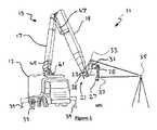
自動レンガ積み機械11は、トラック13の形態をしている車両の周りに構築され、長い伸縮自在ブーム17と伸縮自在スティック19とを備える、全体を符号15で表された伸縮式多関節ブーム組立体を支持する基部を有している。スティック19の遠隔端21へは、積み上げヘッド23の形態をしている末端効果器が取り付けられており、積み上げヘッド23は、レンガ29を操る更なる末端効果器27を動かす6軸ロボットアーム25を支持している。ロボットアーム25はロボット基部31を有しており、ロボット基部31の上方には、6自由度(6DOF)高データレート位置センサ33の形態をしている第1ターゲットが取り付けられていて、位置センサ33は固定地上基準35に対しての6DOF位置座標を制御システムへ提供する。末端効果器27の真上の、ロボットアーム25の端には、6自由度(6DOF)高データレート位置センサ37の形態をしている第2ターゲットが取り付けられていて、位置センサ37は固定地上基準35に対しての6DOF位置座標を制御システムへ提供する。 The automatic brick stacking machine 11 is constructed around a vehicle in the form of a
ヘッド23は、スティック組立体19の遠隔端(ブーム15の遠隔端)であって、枢動水平軸38(車両13が何らのねじれもなく安定したレベルにあると仮定した場合に、車両の状態に関して水平である軸)の周りに、支持されている。 The
全体としての実施形態では、車両13はブーム15を支持し、ブーム15はロボットアーム25を支持し、ロボットアーム25は末端効果器27を支持している。ヘッド23がブーム15とロボットアーム25との間で、随意に省略されてもよいが、末端効果器27によって遂行されるタスク、特にレンガ積み用途での接着剤の塗布を考えると、ヘッド23を含む方がより実用的である。 In the embodiment as a whole, the
車両13は、静止した状態で駐車されていてもよいし、又は支持脚39でジャッキアップされていてもよい。或る代替形として、車両13は、経路に沿って動くように第1CNCチャネルでプログラムされていてもよいし、又は経路に沿って手動で駆動されてもよい。この場合、6自由度(6DOF)高データレート位置センサ41の形態をしている更なる第3のターゲットが提供され、位置センサ41が同じく固定地上基準35に対しての6DOF位置座標を制御システムへ提供する。車両が経路をこの方式で横断してゆく場合、固定地上基準35と同じ型式の複数の固定地上基準が必要になるであろう。代替的に、別の実施形態では、GPSの様な、低データレートかつ低精度の位置センサが利用されることもできるが、高データレートのほうが好ましい。 The
より高速なデータ処理のためには、図2に描かれている様に、それぞれのセンサ33、37、及び41が専用の複数の地上基準35a、35b、35cを有することが望ましい。 For faster data processing, it is desirable that each
ブーム15は、ブームの(先端に配置されている)自身の末端効果器のTCPを要求される座標へ動かすために、第2CNCチャネルでプログラムされる。 The
ロボットアーム25は、タスクを行うために、自身の末端効果器27のTCPを動かすように、第3CNCチャネルでプログラムされる。 The
末端効果器27は、極めて高精度な作業のための、細密動的補償機構を、随意に含んでもよい。その様なシステムは、レーザー切断、型彫り、又は3D付加的レーザー溶融加工のための、高パワーレーザーと共に使用されるガルバノミラーを含んでもよい。末端効果器は、細密動的補償機構のTCPを動かすために、第4CNCチャネルでプログラムされる。 The
図4を参照すると、最も好適な実施形態の詳細が示されている。トラック13の形態をしているブーム基部から支持されているブーム15のための制御システムが提供されている。ブーム15は、スティック組立体19の遠隔端において、水平方向枢動軸38周りに、取り付けられているヘッド23を有している。ロボットアーム25は、ロボット基部31によってヘッド23へ取り付けられている。レンガを拾い上げるグリッパを備える末端効果器27は、ピッチ、ロール、及びヨー運動するように、ロボットアーム27の端へ取り付けられている。制御システムは、ヘッド23を、ひいてはロボット基部31をプログラムされた場所へ位置決めするために、ブーム15を車両13に対して動かす、油圧ラム45及び47(並びにトラック車体内の回転機構、図示せず)の形態をしているブームアクチュエータとインターフェース接続されているブームコントローラを含んでいる。制御システムは、更に、前記末端効果器をプログラムされた位置及び向きに位置決めするために、ロボットアームアクチュエータとインターフェース接続されているロボットアームコントローラを含んでいる。トラッカーシステムは、ロボット基部31に近接するオフセットに配置されている第1ターゲット33の位置を追跡するための固定地上基準35aを有している。トラッカーシステムは、末端効果器27のTCPから、TCPオフセットを持たせて配置されている、2つの第2ターゲット49のうちの一方(どちらでもよいが視認できる方)の位置及び向きを追跡するための、固定地上基準35bを有している。トラッカーシステムは、第1ターゲット33の位置を追跡し、データを前記ブームコントローラへ送り、前記ブームアクチュエータを低速動的応答で動作させ、前記第1ターゲット33を前記オフセットに接近して動的に位置決めさせ、前記ロボット基部31を前記プログラムされている場所に接近して位置決めし、末端効果器27が自身の作業を遂行することを要求されている位置の範囲内に入るようにする。ターゲット49は末端効果器27と共に動き、末端効果器は6自由度で動くことができることから、トラッカーシステムは、前記第2ターゲットの位置及び向きの両方を6自由度で追跡し、データをロボットアームコントローラへ送り、前記ロボットラームアクチュエータ(末端効果器を含む)を高速動的応答で動作させ、前記第2ターゲットを前記プログラムされた位置及び向きからの前記TCPオフセットへ動的に位置決めさせ及び向き付けさせる。 Referring to FIG. 4, details of the most preferred embodiment are shown. A control system is provided for a
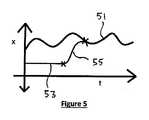
制御システムは、ロボットアームコントローラの制御を、ロボットアームコントローラがトラッカーシステムから導き出される位置決めフィードバックデータに応答する第1状態と、ロボット基部(ひいてはブームの遠隔端)に対し参照される事前較正された位置決めデータが依拠される第2状態との間で、制御可能に切り替えてもよい。末端効果器27でのロボット基部31に対する運動が図5にトレース51によって表現されていて、ブームへの力学的な構造的影響、風偏、又は車両運動に起因する偏差が示されており、またロボットアームの第2状態位置が符号53で表されている。第1状態と第2状態との間で切り替えられると、前記ロボットアームコントローラは、ロボットアームの運動を制御して、トレース55によって表されている第1状態と第2状態との間の遷移を通してロボットアームの運動を減衰させ又は平滑化して、前記ロボットアーム及び前記末端効果器の突発運動を回避させる。その様な突発運動は、ブームへフィードバックされ、ブームに反作用的な運動を被らせ得る。 The control system controls the robot arm controller in a first state in which the robot arm controller is responsive to positioning feedback data derived from the tracker system and a pre-calibrated positioning referenced to the robot base (and hence the remote end of the boom). Controllable switching between the second state on which the data is relied upon may be performed. The movement of the
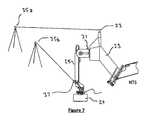
第1状態と第2状態との間の切り替えは、例えば機械の部分からレンガを取り上げ次いでレンガを地表に対して壁の上に積んでゆく場合に、末端効果器が機械構造に対して制御されると、次は地表に対して制御されるというように交番式に制御されることを必要とする、用途に対処している。図6は、ブームの端からレンガを取り上げている末端効果器27を示している。この構成では、制御システムは第2状態にあり、トラッカーシステムは第1ターゲット33を追跡することのみを必要とする。図7は、レンガを積もうとしている末端効果器27を示している。この構成では、制御システムは第1状態にあり、トラッカーシステムは第1ターゲット33と第2ターゲット37とを追跡しなくてはならない。制御システムは、末端効果器の運動を減衰させるために、約1秒をかけてゆっくりと、第2状態から第1状態へ遷移してゆき、逆もまた同様である。補償がすぐにオンにされたりオフにされたりすると、補償ロボットの姿勢は即座に変化する必要に迫られることになり、極めて大きい力と外乱とをブームに与えてしまう。この課題を克服するには、補償量が、通常は0.2秒から0.5秒(又は大型機械については10秒にも及び若しくは小型機械についてはおそらくミリ秒の桁ほど低く最大で0.1秒に及ぶ)の時間をかけて段階的に要求量へ増加又は減少させるように、オン若しくはオフへ遷移される又は減衰されることが必要である。動的基部座標系の場合、基部座標系をそれのプログラムされている位置から実際の位置へ時間をかけて動かすことによって遷移の効果を実現させることが必要である。適用されることになる補償量が補償ロボットの作業範囲内にあることをチェックすることが重要である。これは、ロボットの姿勢が作業枠内に入るはずであることをチェックすることによって行われる。(計算されて適用される補償量が、末端効果器をそれの作業範囲を越えて動かす場合、又はロボットアームのジャーク、加速度、又は速度の力学的限界を超過する場合、)動的基部座標系の実際の位置及び向きが、ロボットをそれの軸移動の作業範囲を越えた姿勢に又はTCPをロボットアームの作業枠の外に置くことになるか、又は末端効果器のジャーク、加速度若しくは速度の力学的限界を超過してしまうならば、基部動的座標系のプログラムされた場所から実際の場所へのシフト量(又は補償量の適用)が減少されるようにしてもよく、又はシステムがそれの作業範囲内へ戻されるまで動きが保留されるようにしてもよく、及び/又はコントローラ内で警告が発せられるようにしてもよい。 Switching between the first state and the second state is such that the end effector is controlled with respect to the machine structure, for example when picking up bricks from the machine part and then loading the bricks against the ground on the wall. Then, it addresses applications that need to be controlled in an alternating fashion, such as the next being controlled against the ground. FIG. 6 shows the
動的補償遷移は、補償がオンにされる場合には0から1の間の遷移係数で増分させることによって、又は補償がオフにされる場合には0から1の間の遷移係数で減分させることによって機能し、その結果、それのS字曲線は所望の時間をかけて傾斜してゆくことになり、そのとき各制御サイクルについて以下が行われる、即ち、
先端トラッカーの実際の6DOF座標を測定する。精細ロボットの基部の実際の座標系の6DOF座標を計算する、
遷移係数が1であれば、その場合、精細ロボットの基部の実際の座標系を動的座標系として使用する。
遷移係数が1でないならば、その場合:
ブーム先端のプログラムされている位置を考察し運動学的変換を精細ロボットの基部へ加えることによって、精細ロボットの基部の座標系のプログラムされている位置を決定する。
遷移係数が0であれば、その場合、座標系のプログラムされている位置を動的座標系として使用する。
遷移係数が0から1の間であれば、その場合:
精細ロボットの基部の、プログラムされている座標系から実際の座標系までの、6DOFデルタベクトルを計算する。
6DOFベクトルを遷移係数でスケール調整して、スケーリングされたベクトルを得る、
スケー調整されたベクトルを座標系のプログラムされている位置へ加えて、動的座標系を得る。
精細ロボットがそれの作業範囲内にあることを確約するために、姿勢と力学をチェックする。警告アルゴリズム、保留アルゴリズム、又はスケーリングアルゴリズムへ進む。
遷移係数が1未満であれば、望ましくはS字曲線式を用いて、遷移係数を増加する。The dynamic compensation transition is decremented by incrementing with a transition factor between 0 and 1 when compensation is turned on, or with a transition factor between 0 and 1 when compensation is turned off. So that its sigmoidal curve slopes over the desired time, and then for each control cycle:
Measure the actual 6 DOF coordinates of the tip tracker. Calculate the 6DOF coordinates of the actual coordinate system of the base of the fine robot,
If the transition coefficient is 1, in that case, the actual coordinate system of the base of the fine robot is used as the dynamic coordinate system.
If the transition coefficient is not 1, then:
The programmed position of the coordinate system of the base of the fine robot is determined by considering the programmed position of the boom tip and applying a kinematic transformation to the base of the fine robot.
If the transition coefficient is 0, then the programmed position of the coordinate system is used as the dynamic coordinate system.
If the transition coefficient is between 0 and 1, then:
Compute the 6 DOF delta vector from the programmed coordinate system to the actual coordinate system at the base of the fine robot.
Scale the 6DOF vector with a transition factor to obtain a scaled vector,
The scaled vector is added to the programmed position of the coordinate system to obtain a dynamic coordinate system.
Check posture and mechanics to ensure that the fine robot is within its working range. Proceed to alert algorithm, hold algorithm, or scaling algorithm.
If the transition coefficient is less than 1, the transition coefficient is preferably increased using an S-curve equation.
前記機械は前記ヘッドへ取り付けられているトラッカー構成要素を含んでおり、前記ヘッドは前記末端効果器を備える前記ロボットアーム組立体を有していて、前記機械はトラッカーシステムを使用してトラッカー構成要素の位置及び向きを測定し、前記測定を使用して前記ロボットアーム組立体について基部座標系の位置及び向きを計算する、ことが望ましい。ロボットアーム末端効果器のTCPは、ヘッドへ固定されている座標系か又は加工品へ固定されている(地表へ固定されている)座標系のどちらかで、タスクを行うようにプログラムされる。プログラミングは、ヘッド座標系又は加工品座標系の間でシフトすることができる。切り替えは、遷移によって行われる。遷移は、以下に解説されている。 The machine includes a tracker component attached to the head, the head having the robot arm assembly with the end effector, and the machine uses a tracker system to track the component. And measuring the position and orientation of the base coordinate system for the robot arm assembly using the measurement. The robot arm end effector TCP is programmed to perform tasks in either a coordinate system fixed to the head or a coordinate system fixed to the work piece (fixed to the ground). Programming can be shifted between the head coordinate system or the workpiece coordinate system. Switching is performed by transition. Transitions are described below.
動的基部座標系へ遷移することは、動的基部座標系を、理論上の完璧な位置及び向きから、実際の位置及び向き(ヘッドへ固定されているトラッカー構成要素の位置及び向きの測定によって得られる)へ、段階的かつ制御されたやり方で、移動することを含む。 Transitioning to the dynamic base coordinate system changes the dynamic base coordinate system from the theoretically perfect position and orientation to the actual position and orientation (by measuring the position and orientation of the tracker component fixed to the head). To move in a step-wise and controlled manner.
動的基部座標系から遷移することは、動的基部座標系を、実際の位置及び向き(ヘッドへ固定されているトラッカー構成要素の位置及び向きの測定によって得られる)から、プログラムされている(即ち、理論上の)完璧な位置及び向きへ、段階的かつ制御されたやり方で、動かすことを含む。 Transitioning from the dynamic base coordinate system is programmed from the actual position and orientation (obtained by measuring the position and orientation of the tracker component fixed to the head) ( That is, moving in a stepwise and controlled manner to a perfect (theoretical) position and orientation.
この構成への最も洗練された数学的手法は、ブームTCPと先端トラッカー中心点とロボットアームの基部の動的座標系とを、一致させ整列させることである。このやり方では、ブームCNCチャネルに設定された運動学的変換は、それのTCPを、先端トラッカー中心点と一致させる。ロボットアームCNCチャネルの運動学的変換は、それの動的基部座標系を、先端トラッカーと一致させる。 The most sophisticated mathematical approach to this configuration is to align and align the boom TCP, the tip tracker center point, and the dynamic coordinate system of the base of the robot arm. In this manner, the kinematic transformation set for the boom CNC channel causes its TCP to coincide with the tip tracker center point. The kinematic transformation of the robot arm CNC channel makes its dynamic base coordinate system coincide with the tip tracker.
当業者に理解される様に、ブームTCPがヘッド基部動的座標系と異なる位置及び先端トラッカー中心点と異なる位置にあった場合、ロボットアーム基部動的座標系の理論上の完璧な位置を計算するために数学的変換を使用できる。これは、一致したブームTCPと先端トラッカーCPとロボットアーム基部動的座標系と、に関する上記の概説よりも、複雑で洗練さに欠ける解決策である。 As understood by those skilled in the art, the theoretical perfect position of the robot arm base dynamic coordinate system is calculated when the boom TCP is at a different position from the head base dynamic coordinate system and different from the tip tracker center point. Mathematical transformations can be used to This is a more complex and less sophisticated solution than the above review of the matched boom TCP, tip tracker CP, and robot arm base dynamic coordinate system.
制御システムは、動的座標系オフセット又は複数の動的座標系オフセットを用いて、ロボットアームの基部座標系をリアルタイムで地上座標系にシフトさせる。次いで、制御システムは、運動学的変換を用いて、末端効果器を、ロボット基部座標系ではなく、地上座標系のプログラムされた位置に位置決めするために要求される関節位置(角関節又は直線関節)を計算する。 The control system shifts the base coordinate system of the robot arm to the ground coordinate system in real time using the dynamic coordinate system offset or the plurality of dynamic coordinate system offsets. The control system then uses the kinematic transformation to locate the end effector at the programmed position in the ground coordinate system, not the robot base coordinate system (angular or linear joint). ).
広い区域のタスクについては、車両を地上に対して動かすことが必要なこともある。地表に対する車両運動は、自動で制御されることもあれば、事前に計算されたガイドライン内で手動で制御されることもある。何れの場合も、機械基部の場所は、車輪若しくは軌道、チェーン若しくはレール、又は脚部及び足部、の何れかによって、案内され、あまり高精度ではないかもしれない。この場合、多段制御システムが使用され、第1段は車両を大まかに位置決めし、第2段は、ブームを所望の先端場所へ位置決めし、車両の位置及び向き並びにブームの撓みに起因する何らかの誤差を低速で補正し、第3段は、第3段ロボットアーム基部座標系の位置及び向きを測定し、次いで、末端効果器を地上座標系に対して安定させ案内するように精密に位置決めし補償する。測定及び制御の段数は、任意の複数の制御システム、動的座標系、及び測定システムへ拡大されてもよい。安定性のためには、制御の帯域及びモーションシステムの機械的応答速度が車両から末端効果器に向かって増加することが重要である。 For large area tasks, it may be necessary to move the vehicle relative to the ground. Vehicle motion relative to the ground surface may be controlled automatically or manually within pre-calculated guidelines. In any case, the location of the machine base is guided by either wheels or tracks, chains or rails, or legs and feet and may not be very accurate. In this case, a multi-stage control system is used where the first stage roughly positions the vehicle and the second stage positions the boom to the desired tip location and any errors due to vehicle position and orientation and boom deflection. The third stage measures the position and orientation of the third stage robot arm base coordinate system, and then precisely positions and compensates to stabilize and guide the end effector relative to the ground coordinate system. To do. The number of measurement and control stages may be extended to any number of control systems, dynamic coordinate systems, and measurement systems. For stability, it is important that the bandwidth of control and the mechanical response speed of the motion system increase from the vehicle towards the end effector.
一部の状況では、末端効果器を、地表に対してではなく動く物体に対して安定させることが必要である。車両座標系及び先端トラッカー座標系の相対位置が動く物体の座標系に対して測定されるならば(逆も然り)、車両と比べ、動く物体は、それが慣性的に固定された座標系では無いことを別にすれば、地表と同等であると見なされ得る。この場合、慣性的に固定された座標系(例えばゆっくりと回転する座標系ではあるが地球又はINS)に対する測定も、動きの力学的限界を観測できるようにするために、行われることが望ましい。 In some situations it is necessary to stabilize the end effector against moving objects rather than against the ground. If the relative position of the vehicle coordinate system and the tip tracker coordinate system is measured with respect to the moving object's coordinate system (and vice versa), the moving object has a coordinate system in which it is inertially fixed compared to the vehicle. Apart from that, it can be regarded as equivalent to the earth's surface. In this case, measurements on an inertially fixed coordinate system (eg, slowly rotating coordinate system but the Earth or INS) are also preferably made in order to be able to observe the mechanical limits of motion.
制御システムは、自動レンガ積み、精密採鉱、機械加工、ロボット組立、塗装、及び3D印刷の様なタスクに使用することができる。それは、インフラストラクチャーであるパイプライン、鉄道、及び道路の建設のための自動溝開削、自動管埋設並びに高速道路防音壁の様な長尺壁の建築のための、特定の用途を有している。 The control system can be used for tasks such as automated brickwork, precision mining, machining, robot assembly, painting, and 3D printing. It has specific applications for construction of long walls such as automatic grooving, automatic pipe burial and highway noise barriers for the construction of infrastructure pipelines, railways and roads .
本発明は、浚渫、護岸建設、油田及び風力タービンの保守整備、乗員輸送、船舶間若しくは航空機間の移送若しくは燃料補給、又は、ヘリコプター送電線保守整備若しくはヘリコプターロギングの様な用途のための、空中又は海上に浮いている設備へ適用することができる。 The present invention provides a Or it can be applied to equipment floating on the sea.
発明は、多様な運動学的連鎖及び多様な動的座標系に適用される。発明は、動く機械上にあるブームへ付着されている末端効果器を地表に対して安定させるために特に有用である。機械が動くと、機械の加速度がブームへ力学的な力を与え、ブームはその固有振動数で振れ始める。ブームの端部の補償ロボットが、ブームの動きの振幅よりも大きい振幅を有し、ブーム(及び車両)の固有振動数よりもはるかに速い応答を有している場合、補償ロボットは、車両走行からのバウンドに起因するブームの動きを補正することができる。補償ロボットは、あまり大きな可動域を有しておらず、よって、補償ロボットをそれの利用できる可動域内に引き留めるためにブームの姿勢を補正することも必要である。 The invention applies to various kinematic chains and various dynamic coordinate systems. The invention is particularly useful for stabilizing an end effector attached to a boom on a moving machine relative to the ground. As the machine moves, the acceleration of the machine applies a mechanical force to the boom and the boom begins to swing at its natural frequency. If the compensating robot at the end of the boom has an amplitude greater than the amplitude of the boom movement and has a response much faster than the natural frequency of the boom (and vehicle), the compensating robot will It is possible to correct the movement of the boom caused by the bouncing from. The compensating robot does not have a very large range of motion, so it is also necessary to correct the attitude of the boom in order to keep the compensating robot within its available range of motion.
補償ロボットの作動は力学的な力をブームに与え、それが今度は更にブームを活性化する。ブームの衝動的な動きを最小限にするためには、ブームは剛性であること、そして機械的遊びもバックラッシュも無いことが望ましい。 The operation of the compensating robot imparts a mechanical force to the boom, which in turn activates the boom further. In order to minimize the impulsive movement of the boom, it is desirable that the boom be rigid and free of mechanical play and backlash.
(随意の)動く車両は滑らかに走行することが望ましく、よって、車両が進んでゆく地表は地ならしされていることが望ましく、また車両はサスペンションを有していることが望ましい。サスペンションはセルフレベリング式であることが理想的である。随意に、車両が地表の上を走行するより先に、地表を水平化するように制御可能なブレードを車両に備え付けてもよい。随意に、末端効果器がブレード又はバケットであってもよく、機械が自身の経路を進んでゆくのに先立って地ならしし水平化してもよい。 It is desirable that the (optional) moving vehicle travels smoothly, so that the ground on which the vehicle travels is preferably leveled and the vehicle has a suspension. The suspension is ideally self-leveling. Optionally, the vehicle may be equipped with blades that are controllable to level the surface before the vehicle travels over the surface. Optionally, the end effector may be a blade or bucket, and leveling may be done prior to the machine traveling its path.
機械及びブームの衝動的な動きを最小限にするために、機械の車両の制御システムが、動きを慎重に制御するために使用される。望ましくは、安定した末端効果器の動作が所望されるときに、動作モードが設定され得る。車両及びブームの動きは、ジャーク、加速度、及び速度が制限されていることが望ましい。電気油圧制御システムでは、電気的パイロットシステムが、利用可能な制御入力を制限するように制御される。サーボ電気システムでは、サーボ力学が、望ましくはCNCチャネル及び軸構成によって、制限される。設定点又はポイント・ツー・ポイント動き制御ではなく、完全CNC経路プランニングが利用されることが望ましい。完全CNC経路プランナーは、制御サイクルごとに(通常はmsごとに)、経路点を計算する。望ましくは、位置、速度、加速度、及びジャークを最適化するために、経路を計算する。ポイント・ツー・ポイント制御は、単純に設定点を所望の端点へ変更するものであり、そのため大きな制御フィードバック誤差値が生じ、フィードバック制御ループは誤差を埋める動きを指令する。 In order to minimize the impulsive movement of the machine and boom, the machine's vehicle control system is used to carefully control the movement. Desirably, the mode of operation can be set when stable end effector operation is desired. Vehicle and boom movement is preferably limited in jerk, acceleration, and speed. In an electrohydraulic control system, an electrical pilot system is controlled to limit the available control inputs. In servo electrical systems, servo dynamics are preferably limited by the CNC channel and axis configuration. It is desirable to use full CNC path planning rather than setpoint or point-to-point motion control. The full CNC path planner calculates path points every control cycle (usually every ms). Preferably, paths are calculated to optimize position, velocity, acceleration, and jerk. Point-to-point control simply changes the set point to the desired end point, resulting in a large control feedback error value, and the feedback control loop commands the movement to fill the error.
車両の位置及び向きの測定値は、6DOF先端トラッカーの測定値から逆算されてもよい(ブームの逆運動学的連鎖を使用する場合、当然ながらブームの撓み又は振動を例えば加速度計によって測定されない限り、考慮に入れることはないが、通常は、動きの振動成分を平滑化するように、厳格にフィルタ処理された先端トラッカー動きを有し得る)。車両の位置及び向きは、機械の車両へ又は掘削機の運転室の様な車両に近い機械の部分へ備え付けられている位置追跡デバイスによって提供されることが望ましい。車両追跡デバイスは、GPS又はトータルステーションターゲットの様な比較的低いデータレート及び低い精度を有しているかもしれないが、レーザートラッカー及びスマート追跡センサの様な高精度センサシステムと一体なら最良の性能が実現されるはずである。 Vehicle position and orientation measurements may be back-calculated from 6DOF tip tracker measurements (unless using boom reverse kinematic chains, of course, unless the boom deflection or vibration is measured by an accelerometer, for example) , Which will not be taken into account, but may typically have a strictly filtered tip tracker motion to smooth out the vibrational component of the motion). The position and orientation of the vehicle is preferably provided by a position tracking device mounted on the machine's vehicle or on a portion of the machine close to the vehicle, such as an excavator's cab. Vehicle tracking devices may have relatively low data rates and low accuracy, such as GPS or total station targets, but perform best with high accuracy sensor systems such as laser trackers and smart tracking sensors. Should be realized.
ブームの動きは、それの固有振動数よりも著しく小さい帯域幅(1%から10%、10%から20%、30%から50%、又は50%から99%)で制御されて、ブームの動き誤差並びに撓み、及び基部の動き誤差又は運動をゆっくりと補償する。ブームの制御される動きは、ブームの先端の位置を補正することを目的としているが、必ずしもブーム先端の向きを補正することを目的とするわけではない。ブームの制御及び応答は、0.1から1Hz、1Hzから10Hz、又は10Hzから30Hzの帯域幅を有していてもよい。末端効果器補償ロボットは、高い固有振動数(ブーム及び基部と対比して)及び高速な動的応答を有していなくてはならない。補償ロボットは、6DOFで補償し安定させる。先端トラッカーの測定システムは、高いデータレート、望ましくは末端効果器制御システムと同じサーボループ制御レート、250Hzの最小値、好適には1000Hz又はそれ以上(おそらくは10kHz)を有していなくてはならない。データレートが著しく低い場合、動的座標系の位置及び向き(最終的には補償入力をもたらす)は、システムがアクチュエータの力の入力に応答する際に構造的な振動を誘発する可能性がある、段階的な変化を有する。滑らかな変化をもたらすために、段階的な変化がフィルタ処理されるならば、遅延及び動きの遅れが導入されてしまい、末端効果器の位置は正確ではなくなり、地表に対して動揺する可能性がある。 The movement of the boom is controlled with a bandwidth (1% to 10%, 10% to 20%, 30% to 50%, or 50% to 99%) that is significantly less than its natural frequency. Slowly compensate for errors and deflections and base movement errors or motion. The controlled movement of the boom is intended to correct the position of the tip of the boom, but is not necessarily intended to correct the orientation of the boom tip. The boom control and response may have a bandwidth of 0.1 to 1 Hz, 1 Hz to 10 Hz, or 10 Hz to 30 Hz. The end effector compensating robot must have a high natural frequency (in contrast to the boom and base) and a fast dynamic response. The compensating robot compensates and stabilizes with 6 DOF. The tip tracker measurement system must have a high data rate, preferably the same servo loop control rate as the end effector control system, a minimum of 250 Hz, preferably 1000 Hz or higher (possibly 10 kHz). If the data rate is significantly low, the position and orientation of the dynamic coordinate system (which ultimately results in a compensation input) can induce structural vibrations when the system responds to the actuator force input. , With gradual changes. If gradual changes are filtered to produce smooth changes, delays and motion delays are introduced, and the position of the end effector is not accurate and can be upset with respect to the ground. is there.
動的座標系の連鎖及び、ブームの補正及びロボットによる末端効果器の補正という連鎖、を有する機械は、大きな作業容量に対する、細密な位置及び動き制御を必要とする多くの用途に有用である。 Machines with a dynamic coordinate system chain and a chain of boom correction and robot end effector correction are useful for many applications that require fine position and motion control for large working capacities.
以下に、一部の例としての用途が与えられている。
船舶移送In the following, some example uses are given.
Ship transfer
船舶対船舶、船舶対オイルリグ、船舶対ガスリグ、又は船舶対風力タービンの、商品、液体、又は人員の移送は、本発明の制御システムに見込まれる用途である。位置保持のために船を安定させることは知られている。ジャイロ又はスラスタを用いて船のロール安定性を図ることも知られている。スラスタを使って船のヨー安定性を図ることは知られている。更に、ブームの様な作業デバイスへ、ヒーブ、ピッチ、ロール、ヨー補償を提供することも知られている。しかしながら、過酷な海上状態での長いブームにとって、既存の補償方法が限界を有していることも知られている。粗いブーム位置決め及び細密な末端効果器位置決め、又は細密位置決めの更なる追加の段が、より広大な海上状態及びより荒れた天候での、より安全な移送、連結、接続解除、及び運行を可能にするはずである。例えば、図9及び図10は、LNGをLNGタンカー57へ移送する、EPSO59(浮体、生産、貯蔵及び積出用の船:Floating, Production, Storage and Offloading vessel)上に取り付けられたブームを示している。ブームは、タンカーへ近づく又は接続することのできる細密位置決めアームを有している。トラッカーは、ブーム先端と細密位置決めアームの先端との、相対位置を測定する。細密位置決めアームがタンカー57と接続又は係合されている場合、制御システムは、受動モード(即ち、積極的な制御無し)へ切り替えられ、そうすると、細密位置決めアームは、これによりブーム先端とタンカーとの間の相対運動を吸収するサスペンションシステムとして機能する。 Ship, ship, oil rig, ship to gas rig, or ship to wind turbine, commodity, liquid, or personnel transfers are potential applications for the control system of the present invention. It is known to stabilize a ship for position maintenance. It is also known to use a gyro or thruster to achieve ship roll stability. It is known to use a thruster to provide ship yaw stability. It is also known to provide heave, pitch, roll, and yaw compensation for work devices such as booms. However, it is also known that existing compensation methods have limitations for long booms in harsh sea conditions. Coarse boom positioning and fine end effector positioning, or additional stages of fine positioning, allow for safer transport, connection, disconnection, and operation in wider maritime conditions and in harsh weather Should do. For example, FIGS. 9 and 10 show a boom mounted on an EPSO 59 (Floating, Production, Storage and Offloading Vessel) that transfers LNG to the
図11を参照すると、描かれている様に、供給船63の甲板上のスチュワートプラットフォーム71によって、オイルリグ若しくはガスリグ65又はFPSO(浮体、生産、貯蔵及び積出用の船)に対して、6自由度で安定化されているプラットフォームは、リグ又はFPSO上の既存のクレーンを使用して、はるかに安全な商品及び人員の移送を可能にするはずである。リグ65上のトラッカー67が船63上のターゲット69を追跡する一方で、船上のトラッカー35aがブーム15の端のターゲット33を追跡する。このデータは、必要に応じ、ブーム15及び末端効果器27を論じられている様に制御するために、リグ上のブームの基部と共に配置されている制御システムへ無線リンク経由で送られ、そして更に、船63の甲板上のスチュワートプラットフォーム71の制御を支援するようにフィードバックされてもよい。これは、大きくて高価な物品を取り扱う場合に特に重要な運用上の利点を提供する。現状では、海上状態が限界に達すると移送は中断されざるを得ない。 Referring to FIG. 11, as depicted, the Stewart platform 71 on the deck of the
これは、あらゆる気象条件で、船から船へ又は船から固定された物体へ、移動することを必要とする又は所望する、石油化学、再生可能エネルギー、及び軍事関連のオペレーター(その他の人)のための、多大な利益となる。
長尺建造物This is the case for petrochemical, renewable energy and military operators (others) who need or desire to move from ship to ship or from a ship to a fixed object in any weather condition. Because of that, it will be a huge profit.
Long building
高速道路防音壁61の様な長尺建造物は、レンガ積み機械によって築かれることができるが、これまでに特許出願第20169号に記載されている構成の場合、1つの場所から築き、次いで周期的に元の位置に戻し、次の静止場所から築くことが必要である。クリーピング機械から築くことができれば好都合である。これは、元の位置に戻すための損失時間を低減し、より短いブームを持つ、より小型でコンパクトな機械を可能にするはずである。短いブームのトラック搭載型の機械が理想的である。これを容易にするために、図8に示されている様に、複数の固定地上基準35が提供される。
長尺溝掘りA long building such as the highway sound barrier 61 can be built by a brickworking machine, but in the case of the configuration described so far in patent application No. 20169, it is built from one place and then periodically It is necessary to return to the original position and build from the next stationary place. It would be advantageous if it could be built from a creeping machine. This should reduce the lost time to return to the original position and allow for a smaller and more compact machine with a shorter boom. A short boom truck mounted machine is ideal. To facilitate this, a plurality of fixed ground references 35 are provided as shown in FIG.
Long ditch digging
地中パイプライン及び地中ケーブルの様なインフラストラクチャーのための長尺溝は、既知の継続溝掘り機械(例えば、ディッチウィッチ(Ditch Witch)社製又はヴァーミヤー(Vermeer)社製など)を用いて掘削されることができ、又は、より広い断面の溝は、掘削機(例えば、キャタピラー(Caterpillar)社製、ボルボ(Volvo)社製、ジョンディア(John Deere)社製、コマツ(Komatsu)社製など)を用いて、掘削されることができる。多くの用途にとって、溝及び管の精密な勾配及び位置が重要であり、例えば下水道管などの場合がそうである。多くの用途にとって、精密な位置を知るということは重要であり、例えば都市では、管、ケーブル、基礎、及び地下鉄や道路のトンネルの様な既存のインフラストラクチャーに損傷を与えることを避けるために重要である。現在のシステムは、掘削の或る程度の制御を許容していて、オペレータへ掘削深度又はバケット位置のフィードバックを提供している。現在のシステムでは、機械(トラック)の基部は静止していなくてはならない。Long gutters for infrastructure such as underground pipelines and underground cables are made using known continuousgrooving machines (eg, Ditch Witch or Vermeer). Grooves that can be drilled or have a wider cross-section are excavators (e.g., Caterpillar, Volvo, John Deere, Komatsu) Etc.) can be drilled. For many applications, the precise slope and position of the grooves and pipes are important, for example in the case of sewer pipes. For many applications it is important to know the precise location, for example in cities, to avoid damaging existing infrastructure such as pipes, cables, foundations, and subway and road tunnels. It is. Current systems allow some control of drilling and provide operator feedback on drilling depth or bucket position. In current systems, the base of the machine (truck) must be stationary.
説明されている動的制御システムは、他の方法では現在実現され得ない公差まで精密な掘削を可能にさせる。そのうえ、それは、完全自律運用のための、事前プログラムされた掘削を可能にさせる。しかも、それは、提案されている溝の経路に沿って徐々に進む無限けん引式掘削機の様な継続的に動く機械からの精密掘削を可能にさせる。
地表輪郭削りThe described dynamic control system allows for precise drilling to tolerances that would otherwise not be possible at present. Moreover, it allows pre-programmed excavation for fully autonomous operation. Moreover, it allows precision drilling from continuously moving machines such as the endless towing excavator that gradually progresses along the proposed groove path.
Ground contour cutting
地面又はコンクリート面をブレード又はバケットで平らにするために、地ならし機、ブルドーザー、ローダー、グレドール、又は自動均し機械を使用することは知られている。機械の特有の設計は、機械の幾何学形状が平らにする行為を提供するために、機械が移動してゆくよりも平坦な面を実現する。バケット又はブレードを事前に定義されている高さ、勾配、又は輪郭に関して維持するために、自動制御を用いて、より正確で高速な結果が実現され得ることが知られている。ブレード又はバケットは、レーザー平面のレベル又は勾配を維持するように、又は、GPS又はトータルステーション測定によって参照される輪郭に整合させるように、自動的に上下動され又はロール軸周りに傾けられる。これらの既知の制御システムは低い帯域幅を有しており、機械は、機械誘導が無くとも、それの特有の設計が、機械が走行してゆくよりも平坦な面を実現させることになるので、正確な結果を実現する。 It is known to use leveling machines, bulldozers, loaders, Gredors or automatic leveling machines to flatten the ground or concrete surface with blades or buckets. The machine's unique design provides a flat surface rather than the machine moving to provide the act of flattening the machine geometry. It is known that more accurate and faster results can be achieved using automatic controls to maintain buckets or blades with a predefined height, slope, or profile. The blade or bucket is automatically moved up and down or tilted about the roll axis to maintain the level or slope of the laser plane or to match the contour referenced by GPS or total station measurements. These known control systems have a low bandwidth, and the machine, even without machine guidance, will allow its unique design to achieve a flatter surface than the machine will travel on. Realize accurate results.
本発明は、極めて複雑な地ならしタスクを完全にプログラム可能なやり方で実現するために、(修正された)掘削機の様な、より複雑な機械構成が、多軸制御型ブレード又はバケットを備え付けられることを可能にする。
採鉱The present invention allows a more complex machine configuration, such as a (modified) excavator, to be equipped with multi-axis controlled blades or buckets in order to implement extremely complex leveling tasks in a fully programmable manner. Make it possible.
mining
採鉱のために自律式トラックを使用することは知られている。 It is known to use autonomous trucks for mining.
掘削機及びフェースショベルは、現在は、機械オペレータによって操作されている。本技術は、基部運動(トラック基部)及び掘削プログラムを鉱山座標で事前にプログラムすることにより、掘削機及びフェースショベルの自律制御を可能にする。
浚渫Excavators and face excavators are currently operated by machine operators. The present technology enables autonomous control of excavators and face excavators by pre-programming base movement (track base) and excavation programs with mine coordinates.
dredging
浚渫には、艀に搭載された掘削機が使用される。浚渫される水路の深さ、幅、外形、及び場所は、船舶輸送の安全性にとって極めて重要である。浚渫は費用がかかり、したがって、移動させる浚渫土の量を最小限にすることが有利である。浚渫が高精度であるほど、移動させる必要のある浚渫土は少なくなる。 For the dredge, an excavator mounted on the dredge is used. The depth, width, profile, and location of the dredged waterways are critical to ship transport safety. Dredging is expensive and therefore it is advantageous to minimize the amount of dredged soil that is moved. The more accurate the dredge, the less dredged soil that needs to be moved.
艀は浮いているので、掘削機が動くと、艀は、縦揺れや、回転や、移動をする。6DOFでの艀の位置及び向きをリアルタイムで測定することは、バケット位置が、(掘削機の姿勢を測定する既知のセンサを介して)精密に計算されることを可能にし、又は事前にプログラムされている一連の掘削場所へ制御されることすら可能にする。
高所作業プラットフォームSince the kite is floating, when the excavator moves, the kite will pitch, rotate and move. Measuring the position and orientation of the kite in 6DOF in real time allows the bucket position to be accurately calculated (via a known sensor that measures the attitude of the excavator) or pre-programmed. It is even possible to be controlled to a series of drilling sites.
Aerial work platform
JLG社、スノーケル(Snorkel)社、及びジーニー(Genie)社の様な製造者によって作られている、ブームリフト又はシザースリフト又は垂直方向伸縮式リフトの様な、様々な種類の高所作業プラットフォーム(EWP:elevated work platforms)を使用することは知られている。非常に背の高いブームリフトは大きな振幅で揺れ、作業を困難、危険、又は実施不能にすることが知られている。揺れは、ブームリフトが動作することのできる高さにとっての制限因子である。プラットフォームを上昇させた状態でブームリフト又はEWPを駆動すると、揺れを引き起こし、プラットフォームを不安感のあるもの又は危険なものにしてしまうことが知られている。本発明は、安定したプラットフォームにするための手段を提供して、プラットフォームが、地表に対して、又はプラットフォーム又はEWPが動かされるときの所望の軌跡に対して安定化されるようにする。
ケーブル懸架型ロボットVarious types of aerial work platforms (such as boom lifts or scissor lifts or vertical telescopic lifts) made by manufacturers such as JLG, Snorkel, and Genie. It is known to use EWP (elevated work platforms). Very tall boom lifts are known to swing with large amplitudes, making work difficult, dangerous, or inoperable. Shaking is a limiting factor for the height at which the boom lift can operate. It is known that driving a boom lift or EWP with the platform raised will cause shaking and make the platform anxious or dangerous. The present invention provides a means for making a stable platform so that the platform is stabilized relative to the ground surface or to a desired trajectory when the platform or EWP is moved.
Cable suspension robot
高架式ガントリー又はタワーによって引張支持されているケーブルに懸架されるプラットフォーム上にロボットを支持することは知られている(PARシステムズ社−引張トラス及びチェルノブイリクレーン及び解体ロボット参照)。ケーブルは高い荷重を支持することができるが、構造は低い剛度を有している。横方向の剛度は非常に低い。ロボット及び末端効果器の位置決めの正確度は、追跡構成要素を懸架型プラットフォームへ追加してロボットアームの基部の6DOF位置を提供させることによって大きく改善されるはずである。これは、その様なシステムに、それが行うべきものとして現在採用されている比較的精度の低い解体作業ではなく、高精度な作業を行わせることを可能にする。
高精度用途It is known to support a robot on a platform suspended on a cable that is tension supported by an elevated gantry or tower (see PAR Systems-Tensile Truss and Chernobyl Crane and Demolition Robot). The cable can support high loads, but the structure has low stiffness. The lateral stiffness is very low. The accuracy of robot and end effector positioning should be greatly improved by adding tracking components to the suspended platform to provide a 6DOF position of the base of the robot arm. This allows such a system to perform high precision work rather than the relatively low precision dismantling work currently employed as it should be done.
High precision applications
その様なシステムは、レーザー切断、レーザー型彫り、又は3D付加的レーザー溶融加工のために、高パワーレーザーと共に使用されるガルバノミラーを含んでいてもよい。 Such a system may include galvanometer mirrors used with high power lasers for laser cutting, laser engraving, or 3D additive laser melt processing.
本発明の範囲はここに説明されている特定の実施形態に限定されないものと理解されたい。 It should be understood that the scope of the present invention is not limited to the specific embodiments described herein.
Claims (16)
Translated fromJapanese前記ブームはロボット基部によってそれから取り付けられているロボットアームを有し、
前記ロボットアームは末端効果器を有し、
前記ブームは、前記ロボット基部をプログラムされた場所へ位置決めするために、ブームアクチュエータとインターフェース接続されているブームコントローラによって、前記ブーム基部に対して可動であり、
前記ロボットアームは、前記末端効果器をプログラムされた位置及び向きに位置決めするために、ロボットアームアクチュエータとインターフェース接続されているロボットアームコントローラによって可動であり;
前記制御システムは、前記ロボット基部に近接するオフセットに配置されている第1ターゲットの位置を追跡するための、及び前記末端効果器TCPからTCPオフセットを持たせて配置されている第2ターゲットの位置及び向きを追跡するための、トラッカーシステムを有し;
前記トラッカーシステムは、前記第1ターゲットの位置を追跡し、データを前記ブームコントローラへ送り、前記ブームアクチュエータを低速動的応答で動作させ、前記第1ターゲットを前記オフセットに接近して動的に位置決めさせ、前記ロボット基部を前記プログラムされた場所に接近して位置決めし、そして、
前記トラッカーシステムは、前記第2ターゲットの位置及び向きを追跡し、前記第2ターゲットから導き出された、又は前記第2ターゲット及び前記第1ターゲットから導き出された、データを前記ロボットアームコントローラへ送り、前記ロボットアームアクチュエータを高速動的応答で動作させ、前記末端効果器TCPを前記プログラムされた位置及び向きへ動的に位置決めさせ及び向き付けさせるようにする、制御システム。A control system for a boom supported from a boom base,
The boom has a robot arm attached thereto by a robot base;
The robot arm has a terminal effector;
The boom is movable relative to the boom base by a boom controller interfaced with a boom actuator to position the robot base in a programmed location;
The robot arm is movable by a robot arm controller interfaced with a robot arm actuator to position the end effector in a programmed position and orientation;
The control system tracks the position of a first target located at an offset close to the robot base and the position of a second target located with a TCP offset from the end effector TCP And a tracker system for tracking orientation;
The tracker system tracks the position of the first target, sends data to the boom controller, operates the boom actuator with a slow dynamic response, and dynamically positions the first target close to the offset. Positioning the robot base close to the programmed location; and
The tracker system tracks the position and orientation of the second target and sends data derived from or derived from the second target to the robot arm controller; A control system that operates the robot arm actuator with a fast dynamic response to dynamically position and orient the end effector TCP to the programmed position and orientation.
Applications Claiming Priority (5)
| Application Number | Priority Date | Filing Date | Title |
|---|---|---|---|
| AU2016902787AAU2016902787A0 (en) | 2016-07-15 | Brick/Block Laying Machine Incorporated in a Compact Vehicle | |
| AU2016902787 | 2016-07-15 | ||
| AUPCT/AU2017/050731 | 2017-07-14 | ||
| PCT/AU2017/050731WO2018009981A1 (en) | 2016-07-15 | 2017-07-14 | Brick/block laying machine incorporated in a vehicle |
| PCT/AU2017/050739WO2018009986A1 (en) | 2016-07-15 | 2017-07-17 | Dynamic compensation of a robot arm mounted on a flexible arm |
Publications (2)
| Publication Number | Publication Date |
|---|---|
| JP2019521872Atrue JP2019521872A (en) | 2019-08-08 |
| JP7014789B2 JP7014789B2 (en) | 2022-02-01 |
Family
ID=60951588
Family Applications (3)
| Application Number | Title | Priority Date | Filing Date |
|---|---|---|---|
| JP2019523146AActiveJP7061119B2 (en) | 2016-07-15 | 2017-07-14 | Brick / block laying machine built into the vehicle |
| JP2019523148AActiveJP7014789B2 (en) | 2016-07-15 | 2017-07-17 | Dynamic compensation for a robot arm mounted on a flexible arm |
| JP2019523147AActiveJP7048597B2 (en) | 2016-07-15 | 2017-07-17 | Computer-aided design for brick and block structures, as well as software that controls machines for building buildings |
Family Applications Before (1)
| Application Number | Title | Priority Date | Filing Date |
|---|---|---|---|
| JP2019523146AActiveJP7061119B2 (en) | 2016-07-15 | 2017-07-14 | Brick / block laying machine built into the vehicle |
Family Applications After (1)
| Application Number | Title | Priority Date | Filing Date |
|---|---|---|---|
| JP2019523147AActiveJP7048597B2 (en) | 2016-07-15 | 2017-07-17 | Computer-aided design for brick and block structures, as well as software that controls machines for building buildings |
Country Status (11)
| Country | Link |
|---|---|
| US (11) | US10635758B2 (en) |
| EP (8) | EP3485112B1 (en) |
| JP (3) | JP7061119B2 (en) |
| CN (8) | CN109790723B (en) |
| AU (11) | AU2017294796B2 (en) |
| BR (2) | BR112019000728B1 (en) |
| CA (1) | CA3030764A1 (en) |
| ES (1) | ES2899284T3 (en) |
| SA (1) | SA519400899B1 (en) |
| WO (8) | WO2018009981A1 (en) |
| ZA (2) | ZA201900745B (en) |
Families Citing this family (162)
| Publication number | Priority date | Publication date | Assignee | Title |
|---|---|---|---|---|
| WO2016122416A1 (en)* | 2015-01-30 | 2016-08-04 | Agency for Science,Technology and Research | Mobile manipulator and method of controlling the mobile manipulator for tracking a surface |
| WO2018006181A1 (en)* | 2016-07-08 | 2018-01-11 | Macdonald, Dettwiler And Associates Inc. | System and method for automated artificial vision guided dispensing viscous fluids for caulking and sealing operations |
| ES2899585T3 (en) | 2016-07-15 | 2022-03-14 | Fastbrick Ip Pty Ltd | Material transport boom |
| ES2899284T3 (en) | 2016-07-15 | 2022-03-10 | Fastbrick Ip Pty Ltd | Vehicle incorporating a brick laying machine |
| WO2019006511A1 (en) | 2017-07-05 | 2019-01-10 | Fastbrick Ip Pty Ltd | Real time position and orientation tracker |
| DE102018200435B3 (en)* | 2017-07-31 | 2018-11-15 | Volkswagen Aktiengesellschaft | Motor vehicle and method for controlling a robot |
| CN111213098B (en) | 2017-08-17 | 2024-03-15 | 快砖知识产权私人有限公司 | Communication systems for interactive systems |
| WO2019033170A1 (en) | 2017-08-17 | 2019-02-21 | Fastbrick Ip Pty Ltd | Laser tracker with improved roll angle measurement |
| CN111212799B (en)* | 2017-10-11 | 2023-04-14 | 快砖知识产权私人有限公司 | Machine for conveying objects and multi-compartment carousel for use therewith |
| CN114687540A (en)* | 2017-11-24 | 2022-07-01 | 亿立科技国际有限公司 | Automation system for painting walls of buildings |
| JP7097691B2 (en)* | 2017-12-06 | 2022-07-08 | 東京エレクトロン株式会社 | Teaching method |
| KR20200105651A (en)* | 2018-01-10 | 2020-09-08 | 스미토모 겐키 가부시키가이샤 | Shovel and shovel management system |
| CN108058157A (en)* | 2018-01-29 | 2018-05-22 | 西安优艾智合机器人科技有限公司 | A kind of crusing robot |
| CN108406768B (en)* | 2018-03-09 | 2021-11-19 | 汇川技术(东莞)有限公司 | Robot calibration method and system based on self-weight and load deformation compensation |
| HUE061786T2 (en)* | 2018-03-27 | 2023-08-28 | Stibe Modul Ab | System and method for pre-fabrication and laying out of coverage of a room surface |
| CN112105587B (en)* | 2018-04-12 | 2024-06-21 | 康宁公司 | Apparatus and method for engaging moving glass ribbon |
| US11235471B2 (en)* | 2018-05-22 | 2022-02-01 | Uatc, Llc | Automated cleaning systems for autonomous vehicles |
| CN108877770B (en)* | 2018-05-31 | 2020-01-07 | 北京百度网讯科技有限公司 | Method, apparatus and system for testing intelligent voice devices |
| CN112689552A (en) | 2018-07-16 | 2021-04-20 | 快砖知识产权私人有限公司 | Active damping system |
| US12214500B2 (en) | 2018-07-16 | 2025-02-04 | Fastbrick Ip Pty Ltd | Backup tracking for an interaction system |
| CN109239111A (en)* | 2018-08-17 | 2019-01-18 | 河北省特种设备监督检验研究院 | A kind of pipeline weld joint nondestructive inspection device |
| EP3613544A1 (en)* | 2018-08-22 | 2020-02-26 | Hilti Aktiengesellschaft | Mobile construction robot |
| WO2020041819A1 (en) | 2018-08-29 | 2020-03-05 | Fastbrick Ip Pty Ltd | Gripping apparatus |
| US12002240B2 (en)* | 2018-09-04 | 2024-06-04 | Fastbrick Ip Pty Ltd. | Vision system for a robotic machine |
| AU2019333928A1 (en) | 2018-09-04 | 2021-04-08 | Fastbrick Ip Pty Ltd | Adhesive cartridge |
| US10751888B2 (en)* | 2018-10-04 | 2020-08-25 | Advanced Intelligent Systems Inc. | Manipulator apparatus for operating on articles |
| US11399462B2 (en)* | 2018-10-31 | 2022-08-02 | Cnh Industrial America Llc | System and method for calibrating alignment of work vehicles |
| CN109634227B (en)* | 2018-11-12 | 2020-09-18 | 歌尔股份有限公司 | Control method, device and system for tooling point feeding |
| US11951616B2 (en) | 2018-11-14 | 2024-04-09 | Fastbrick Ip Pty Ltd | Position and orientation tracking system |
| US11124977B2 (en)* | 2018-12-04 | 2021-09-21 | The Chinese University Of Hong Kong | System and method for constructing a brick structure with a cable-driven robot |
| DE102018132655A1 (en)* | 2018-12-18 | 2020-06-18 | Tvi Entwicklung Und Produktion Gmbh | Transfer plant and transfer process |
| US11389953B2 (en)* | 2019-01-31 | 2022-07-19 | Caterpillar Inc. | Hydraulic delta robot control system |
| SE543122C2 (en)* | 2019-02-05 | 2020-10-13 | Brokk Ab | Method, device and user interface describing an operational state of operation of a demolition robot |
| CN110039526A (en)* | 2019-03-14 | 2019-07-23 | 安徽宇升智能装备有限公司 | A kind of efficient conveying robot |
| WO2020210864A1 (en)* | 2019-04-15 | 2020-10-22 | Fastbrick Ip Pty Ltd | Method and system for designing a block sequence for use in ordering blocks for placement during construction |
| WO2020210863A1 (en)* | 2019-04-15 | 2020-10-22 | Fastbrick Ip Pty Ltd | Method and system for designing block layouts for use in block placement during construction |
| CN110208744B (en)* | 2019-05-21 | 2023-01-31 | 河海大学 | A dual-motor telescopic rotary positioning mechanical feedback system |
| US11607804B2 (en)* | 2019-05-28 | 2023-03-21 | X Development Llc | Robot configuration with three-dimensional lidar |
| US11260413B2 (en)* | 2019-06-17 | 2022-03-01 | The Boeing Company | End effector for delivering material to a surface and associated system |
| GB201909111D0 (en)* | 2019-06-25 | 2019-08-07 | Q Bot Ltd | Method and apparatus for renovation works on a building, including method and apparatus for applying a covering to a building element |
| DE102019117217B3 (en)* | 2019-06-26 | 2020-08-20 | Franka Emika Gmbh | Method for specifying an input value on a robot manipulator |
| CN110405766A (en)* | 2019-07-29 | 2019-11-05 | 南京市晨枭软件技术有限公司 | A kind of the manipulator real-time positioning apparatus and control system of industrial robot |
| CN110781536B (en)* | 2019-09-06 | 2023-07-21 | 久瓴(江苏)数字智能科技有限公司 | Building flat skylight node generation method, system, computer equipment and storage medium |
| DE102019214003A1 (en)* | 2019-09-13 | 2021-03-18 | Alexander Friesen | Method and device for cutting structural elements |
| CN114729515A (en) | 2019-09-17 | 2022-07-08 | 托比亚斯·布雷特 | Constructs and methods for generating constructs |
| DE102019130150A1 (en)* | 2019-11-08 | 2021-05-12 | Tobias Brett | Construction system |
| CN110565919A (en)* | 2019-09-29 | 2019-12-13 | 广东博智林机器人有限公司 | Wood floor installation mechanism and wood floor installation robot |
| EP4056330A4 (en)* | 2019-11-05 | 2022-12-14 | Panasonic Intellectual Property Management Co., Ltd. | Robot control method |
| CN110919630B (en)* | 2019-11-13 | 2021-03-12 | 北京机械设备研究所 | Hydraulic oil cylinder installation manipulator and installation method |
| JP7263217B2 (en)* | 2019-11-27 | 2023-04-24 | 株式会社日立製作所 | CONTROL DEVICE, CONTROL METHOD, AND ROBOT SYSTEM |
| CN110836021A (en)* | 2019-12-03 | 2020-02-25 | 湖南易兴建筑有限公司 | Building block construction robot and construction method |
| AU2020397700A1 (en)* | 2019-12-06 | 2022-06-09 | Robotics Plus Limited | An improved packing robot |
| EP3838500A1 (en)* | 2019-12-17 | 2021-06-23 | Bystronic Laser AG | Construction of gripping tools for a laser cutting machine for absorbing parts |
| CN112452597B (en)* | 2019-12-19 | 2021-12-10 | 乐清市泰博恒电子科技有限公司 | Multi-gun mixed control paint spraying robot based on visual servo |
| US12297084B2 (en)* | 2019-12-27 | 2025-05-13 | Tadano Ltd. | Work machine control system and crane |
| JP7487479B2 (en)* | 2020-01-23 | 2024-05-21 | セイコーエプソン株式会社 | Method for controlling a mobile robot |
| WO2021151082A1 (en) | 2020-01-24 | 2021-07-29 | The Cleveland Clinic Foundation | Hybrid control of a robotic system |
| JP7462437B2 (en) | 2020-03-09 | 2024-04-05 | 株式会社東芝 | ROBOT SYSTEM, PARALLEL LINK MECHANISM, CONTROL METHOD, CONTROL DEVICE, PROGRAM, AND STORAGE MEDIUM |
| CN111475201B (en)* | 2020-03-20 | 2022-11-08 | 吉利汽车研究院(宁波)有限公司 | Method, equipment and storage medium for controlling robot to enter and exit interference area based on PLC |
| CN111456279A (en)* | 2020-04-08 | 2020-07-28 | 广东博智林机器人有限公司 | Brick wall building method and device, computer equipment and storage medium |
| CN111832098B (en)* | 2020-04-21 | 2023-07-18 | 中冶南方城市建设工程技术有限公司 | Method for evaluating traffic organization scheme in municipal road construction period |
| US12385265B2 (en)* | 2020-04-22 | 2025-08-12 | Fastbrick Ip Pty Ltd | Block transfer apparatus and improved clamping assembly for use therewith |
| US11518027B2 (en)* | 2020-05-01 | 2022-12-06 | Abb Schweiz Ag | System and method for robotic assembly |
| US11667380B2 (en) | 2020-05-21 | 2023-06-06 | TVS Holdings, LLC | Cable robot positioning system utilizing a light beam measurement device |
| CN111590579B (en)* | 2020-05-26 | 2022-09-13 | 山东理工大学 | Human-simulated flexible arm resonance suppression method |
| CN111723423B (en)* | 2020-06-08 | 2022-07-22 | 长沙理工大学 | Time-frequency hybrid prediction method and system for vertical vibration of tunnel and soil caused by vehicles |
| CN111775147B (en)* | 2020-06-10 | 2021-07-13 | 北京卫星制造厂有限公司 | Intelligent control system of mobile robot |
| CN111618861A (en)* | 2020-06-12 | 2020-09-04 | 重庆科技学院 | Double-follow-up intelligent arm control method based on four-axis structure |
| CN111776942B (en)* | 2020-06-17 | 2025-03-21 | 深圳元戎启行科技有限公司 | Tire crane driving control system, method, device and computer equipment |
| US20230256649A1 (en)* | 2020-07-03 | 2023-08-17 | The Regents Of The University Of Michigan | Additive manufacturing of engineered cementitious composites |
| EP4179172A4 (en) | 2020-07-08 | 2024-08-07 | Fastbrick IP Pty Ltd | ADHESIVE APPLICATION SYSTEM |
| CA3185104A1 (en)* | 2020-07-09 | 2022-01-13 | Peyman POOSTCHI | System and method for automated production of prefabricated buildings and building components |
| US12390931B2 (en)* | 2020-07-15 | 2025-08-19 | Duke University | Autonomous robot packaging of arbitrary objects |
| CN111775339B (en)* | 2020-07-17 | 2022-05-03 | 桂林航天工业学院 | Floor tile laying device for interior decoration |
| EP3943423A1 (en)* | 2020-07-24 | 2022-01-26 | WestRock Packaging Systems, LLC | System and method of grouping of containers |
| DE112021004072B4 (en)* | 2020-07-29 | 2025-05-22 | Fanuc Corporation | Robot system |
| CN112171657B (en)* | 2020-08-07 | 2023-06-27 | 天津大学 | Large-size cuboid component grabbing device and method based on monocular vision |
| US20230311255A1 (en)* | 2020-08-25 | 2023-10-05 | Cnc Ileri Teknoloji Mohendislik Sanayi Ve Ticaret Limited Sirketi | System for hold, clamp and position objects |
| CN112227749B (en)* | 2020-09-16 | 2022-03-11 | 飞帆集团有限公司 | Masonry engineering construction device and construction process thereof |
| CN112123378B (en)* | 2020-09-18 | 2022-01-14 | 库卡机器人(广东)有限公司 | Robot test system |
| WO2022066800A1 (en)* | 2020-09-23 | 2022-03-31 | Dexterity, Inc. | Velocity control-based robotic system |
| CN116829310A (en)* | 2020-10-02 | 2023-09-29 | 建筑机械股份有限公司 | System and method for accurate and dynamic positioning over a volume |
| US20220108046A1 (en)* | 2020-10-05 | 2022-04-07 | Autodesk, Inc. | Generative design techniques for soft robot manipulators |
| CN112264996B (en)* | 2020-10-16 | 2022-06-14 | 中冶赛迪上海工程技术有限公司 | Steel grabbing machine positioning control method and system |
| CN112412073B (en)* | 2020-10-19 | 2022-08-26 | 山东鼎安升机器人有限公司 | Wall building robot |
| CN112276949B (en)* | 2020-10-21 | 2022-03-11 | 哈工大机器人(合肥)国际创新研究院 | Adjacent joint space-Cartesian space trajectory transition method and device |
| WO2022082267A1 (en) | 2020-10-23 | 2022-04-28 | Fastbrick Ip Pty Ltd | Building methods for use in automated construction |
| CN112428278B (en)* | 2020-10-26 | 2022-11-15 | 北京理工大学 | Control method and device of mechanical arm and training method of man-machine collaborative model |
| US11685051B2 (en)* | 2020-10-29 | 2023-06-27 | General Electric Company | Systems and methods of servicing equipment |
| US12208925B2 (en) | 2020-10-29 | 2025-01-28 | General Electric Company | Systems and methods of servicing equipment |
| US11935290B2 (en) | 2020-10-29 | 2024-03-19 | Oliver Crispin Robotics Limited | Systems and methods of servicing equipment |
| US11992952B2 (en) | 2020-10-29 | 2024-05-28 | General Electric Company | Systems and methods of servicing equipment |
| US12139109B2 (en) | 2020-10-29 | 2024-11-12 | General Electric Company | Systems and methods of servicing equipment |
| CN112407345B (en)* | 2020-11-05 | 2025-02-25 | 天津航天机电设备研究所 | Space manipulator suspends microgravity simulation device |
| CN112431392A (en)* | 2020-11-17 | 2021-03-02 | 浙江铠甲建筑科技有限公司 | Hydraulic climbing scaffold for building construction |
| CN112477734B (en)* | 2020-11-21 | 2021-12-24 | 中铁一局集团有限公司 | Construction pipeline moving device |
| CN112464346A (en)* | 2020-11-27 | 2021-03-09 | 中物智建(武汉)科技有限公司 | Wall brick stacking algorithm and operating system |
| CN112650221B (en)* | 2020-12-03 | 2021-12-03 | 广州极飞科技股份有限公司 | Flat ground path generation method, flat ground path generation device, processing equipment and storage medium |
| CN114589687A (en)* | 2020-12-04 | 2022-06-07 | 山东新松工业软件研究院股份有限公司 | Robot control device |
| CN112609554B (en)* | 2020-12-22 | 2022-11-08 | 朱鑫 | Road repairing device capable of increasing friction coefficient |
| CN112854781B (en)* | 2021-01-14 | 2022-06-17 | 湖南天禹建设有限公司 | Building construction equipment and construction method |
| CN112894752B (en)* | 2021-01-20 | 2022-04-01 | 华中科技大学 | Position searching method of mobile processing robot |
| US12151383B2 (en)* | 2021-02-01 | 2024-11-26 | The Boeing Company | Robotic manufacturing systems and methods |
| CN112775976B (en)* | 2021-02-05 | 2022-05-10 | 深圳市优必选科技股份有限公司 | Task execution control method and device, control equipment and readable storage medium |
| CN113062601B (en)* | 2021-03-17 | 2022-05-13 | 同济大学 | A trajectory planning method for concrete placing robot based on Q-learning |
| US11724390B2 (en) | 2021-03-29 | 2023-08-15 | Samsung Electronics Co., Ltd. | Systems and methods for automated preloading of actuators |
| US11712804B2 (en) | 2021-03-29 | 2023-08-01 | Samsung Electronics Co., Ltd. | Systems and methods for adaptive robotic motion control |
| CN113103230A (en)* | 2021-03-30 | 2021-07-13 | 山东大学 | Human-computer interaction system and method based on remote operation of treatment robot |
| US11731279B2 (en) | 2021-04-13 | 2023-08-22 | Samsung Electronics Co., Ltd. | Systems and methods for automated tuning of robotics systems |
| CN113076573B (en)* | 2021-04-15 | 2021-09-10 | 北京城建设计发展集团股份有限公司 | Computer-aided system for weak current design of rail transit |
| AT525022B1 (en)* | 2021-04-29 | 2023-03-15 | Wienerberger Ag | MOBILE ROBOT WALL SEGMENT MANUFACTURING SYSTEM |
| CN113221348B (en)* | 2021-05-08 | 2024-02-02 | 中交第三航务工程局有限公司 | An analysis method for the operable environmental conditions of engineering ships |
| CN113172886A (en)* | 2021-05-18 | 2021-07-27 | 青岛科技大学 | Intelligent micro-control printing device and intelligent micro-control printing method |
| CN113264203B (en)* | 2021-05-31 | 2022-07-15 | 哈尔滨工业大学 | A multi-objective six-degree-of-freedom microgravity ground simulation system and using method |
| CN113293931B (en)* | 2021-06-04 | 2022-03-01 | 中冶建工集团有限公司 | Masonry wall constructional column construction method |
| CN115494794B (en)* | 2021-06-18 | 2025-07-25 | 广东博智林机器人有限公司 | Kinetic parameter identification method, device, equipment and storage medium |
| CN113246142B (en)* | 2021-06-25 | 2021-10-08 | 成都飞机工业(集团)有限责任公司 | Measuring path planning method based on laser guidance |
| US12291333B1 (en)* | 2021-08-05 | 2025-05-06 | Vecna Robotics, Inc. | System and method of providing a robotic retrieval system in a vehicle for use in delivering items |
| CN113688453B (en)* | 2021-08-23 | 2024-07-12 | 杭州群核信息技术有限公司 | Relative texture paving commodity discharging calculation method and device, electronic equipment and medium |
| CN113766418B (en)* | 2021-08-31 | 2022-07-15 | 中国矿业大学 | An attitude self-correction downhole transportation equipment based on UWB technology and its control method |
| WO2023052834A1 (en)* | 2021-09-29 | 2023-04-06 | General Systems Sg Pte Ltd | A material laying robotic system |
| CN113733102B (en)* | 2021-10-08 | 2022-12-16 | 厦门大学 | Error calibration device for industrial robot |
| CN114236562B (en)* | 2021-11-30 | 2025-08-08 | 北京卫星制造厂有限公司 | Testing method for terminal motion trajectory of space deployment mechanism |
| CN114223469B (en)* | 2021-12-14 | 2023-05-26 | 滁州学院 | Be applied to two fork cutter clamp of turf laying device and get mechanism |
| CN114193635B (en)* | 2021-12-23 | 2024-03-12 | 国泰新点软件股份有限公司 | Method and device for cutting middle beam of constructional engineering |
| CN114227695B (en)* | 2022-01-11 | 2023-09-08 | 中国煤炭科工集团太原研究院有限公司 | Anchor rod support robot working arm track planning method and system |
| EP4463290A1 (en)* | 2022-01-14 | 2024-11-20 | Botbuilt, Inc. | Systems and methods for automated framing construction |
| EP4466120A1 (en)* | 2022-01-21 | 2024-11-27 | Boston Dynamics, Inc. | Systems and methods of coordinated body motion of robotic devices |
| CN114102612B (en)* | 2022-01-24 | 2022-05-03 | 河北工业大学 | A control method of robot end path contour error |
| CN114587806B (en)* | 2022-02-16 | 2023-02-03 | 大连理工大学 | Supplementary intelligent wheelchair of endowment with continuous type arm |
| CN114592810A (en)* | 2022-03-18 | 2022-06-07 | 安徽焕备智能装备制造有限公司 | Be used for integrated intelligent device of coal prospecting drill loading and unloading drilling rod in pit |
| CN114753640B (en)* | 2022-04-01 | 2023-04-07 | 中联重科股份有限公司 | Arm support tail end motion planning method and device, control system and engineering machinery |
| CN119053761A (en)* | 2022-04-20 | 2024-11-29 | 快砖知识产权私人有限公司 | Improvements in robotic block paving machines |
| TWI829148B (en)* | 2022-04-25 | 2024-01-11 | 上博科技股份有限公司 | Warm-up time control method that actively integrates tool data and processing conditions |
| CN116696091A (en)* | 2022-04-27 | 2023-09-05 | 广东博智林机器人有限公司 | Bricklaying device and control method |
| CN114753663A (en)* | 2022-04-29 | 2022-07-15 | 广东博智林机器人有限公司 | Lifting device and brick laying robot |
| CN114918937B (en)* | 2022-05-20 | 2024-10-18 | 埃夫特智能装备股份有限公司 | Spray gun based on position sensing technology and convenient programming device of robot thereof |
| US20230381949A1 (en)* | 2022-05-24 | 2023-11-30 | Anram Holdings | Modular box for component management in mobile robots |
| CN114952773B (en)* | 2022-06-02 | 2025-07-01 | 星猿哲科技(上海)有限公司 | Mobile Robot Based on Motion Compensation |
| CN115009606B (en)* | 2022-06-09 | 2023-05-05 | 国通(成都)新药技术有限公司 | Clamp positioning method and device and application thereof |
| CN115143785A (en)* | 2022-06-30 | 2022-10-04 | 苏州云灵智能科技有限公司 | Brick kiln unloading system and control method thereof |
| FI20225631A1 (en)* | 2022-07-05 | 2024-01-06 | Ponsse Oyj | Method and control system for controlling a boom of a forest work machine |
| CN115215223B (en)* | 2022-07-21 | 2024-12-10 | 华电蓝科科技股份有限公司 | Lifting system of quay crane and quay crane |
| CN115128657B (en)* | 2022-08-09 | 2025-03-25 | 中国人民解放军63653部队 | A multi-degree-of-freedom precise measurement device and measurement method in large-scale space |
| AU2023370523A1 (en)* | 2022-10-26 | 2025-05-08 | Fastbrick Ip Pty Ltd | Transfer robot for handling blocks |
| US20240139961A1 (en)* | 2022-11-02 | 2024-05-02 | Intrinsic Innovation Llc | Real-time robotic end effector control |
| CN115784026B (en)* | 2023-01-18 | 2023-04-07 | 安徽送变电工程有限公司 | Wavefront sensing and imaging combined type three-dimensional tracking system and method for positioning lifting hook |
| CN116276993B (en)* | 2023-03-03 | 2023-12-05 | 中国人民解放军军事科学院国防科技创新研究院 | Air bag type soft mechanical arm hand-eye calibration and measurement method based on cooperative mark |
| US20240346504A1 (en)* | 2023-04-13 | 2024-10-17 | Ebay Inc. | Location-based systems and techniques for minting non-fungible tokens (nfts) |
| US20240359317A1 (en)* | 2023-04-25 | 2024-10-31 | CN-Seamless, Inc. | Modular cnc system |
| NL2035011B1 (en)* | 2023-06-06 | 2024-12-12 | Bouwgroep Dijkstra Draisma B V | Method for generating a building information model for a prefab segment |
| CN116533679B (en)* | 2023-06-14 | 2023-09-29 | 奇诺机器人科技(杭州)有限公司 | Automatic tire changing method based on visual guidance |
| EP4484079A1 (en)* | 2023-06-30 | 2025-01-01 | Baubot GmbH | Tracking system for tracking a mobile robot |
| CN116641565B (en)* | 2023-07-26 | 2023-09-22 | 成都建工装饰装修有限公司 | Installation clamping device suitable for assembled decoration and heat preservation integrated wallboard |
| US20250058468A1 (en)* | 2023-08-18 | 2025-02-20 | Ghost Robotics Corporation | System and method for proprioceptive and responsive robotic door opening |
| CN117227607B (en)* | 2023-11-07 | 2024-01-12 | 国机传感科技有限公司 | Intelligent carrying device for heliostat lenses |
| CN117260740B (en)* | 2023-11-09 | 2024-07-19 | 国网山东省电力公司东营供电公司 | Live working robot body positioning area analysis method, system, terminal and medium |
| CN117532624B (en)* | 2024-01-10 | 2024-03-26 | 南京东奇智能制造研究院有限公司 | Automatic positioning and aligning method and system for guardrail plate installation |
| CN118387768B (en)* | 2024-06-25 | 2024-11-08 | 法兰泰克重工股份有限公司 | A method for optimizing operation paths and intelligently avoiding obstacles |
| CN118650564A (en)* | 2024-07-03 | 2024-09-17 | 浙江大学 | A high-precision waterjet cutting system for curved panels based on visual positioning and its working method |
| CN120269579B (en)* | 2025-06-10 | 2025-09-02 | 香港理工大学深圳研究院 | End effector execution method, device and medium |
| CN120429933A (en)* | 2025-06-26 | 2025-08-05 | 中铁大桥局集团有限公司 | Bridge crane equipment finite element computing resource optimization method and system based on dynamic similarity discrimination |
Citations (9)
| Publication number | Priority date | Publication date | Assignee | Title |
|---|---|---|---|---|
| JPS646719A (en)* | 1987-06-26 | 1989-01-11 | Nec Corp | Robot hand position controller |
| JPH01263362A (en)* | 1988-04-12 | 1989-10-19 | Tokyu Constr Co Ltd | Setting of directly laying concrete mold form for long structure by construction work robot |
| JPH07233640A (en)* | 1994-02-22 | 1995-09-05 | Penta Ocean Constr Co Ltd | Traveling work vehicle for concrete compactor |
| US20030120377A1 (en)* | 2001-12-26 | 2003-06-26 | Lockheed Martin Corporation | Machine for performing machining operations on a workpiece and method of controlling same |
| JP2005283600A (en)* | 2005-06-13 | 2005-10-13 | Kawasaki Heavy Ind Ltd | Position and orientation detection device for movable body |
| JP2007021613A (en)* | 2005-07-13 | 2007-02-01 | Hitachi Plant Technologies Ltd | Construction support method and construction support system |
| JP2009521630A (en)* | 2005-12-30 | 2009-06-04 | ゴールドウィング ノミニーズ ピーティーワイ リミテッド | Automatic brick laying system for building buildings with multiple bricks |
| JP2013527040A (en)* | 2010-05-26 | 2013-06-27 | ザ・ボーイング・カンパニー | Method and system for placing inspection sensors |
| JP2014147997A (en)* | 2013-01-31 | 2014-08-21 | Honda Motor Co Ltd | Moving work robot |
Family Cites Families (547)
| Publication number | Priority date | Publication date | Assignee | Title |
|---|---|---|---|---|
| US1086557A (en) | 1914-02-10 | Theodore J Radke | Water-controlled gas-distributing valve. | |
| US1063575A (en) | 1908-09-23 | 1913-06-03 | American Arch Co | Refractory brick arch for locomotive-boiler furnaces. |
| US1009094A (en) | 1909-02-17 | 1911-11-21 | Theodore C Prouty | Weighing-scale. |
| US1001273A (en) | 1909-06-10 | 1911-08-22 | Ivan H Holden | Concrete block for watering-tanks. |
| US1087630A (en) | 1909-07-23 | 1914-02-17 | Birney C Batcheller | Timing mechanism. |
| US1004179A (en) | 1909-07-28 | 1911-09-26 | American Oxhydric Company | Rail-boring blowpipe. |
| US1007316A (en) | 1910-06-06 | 1911-10-31 | Dorn Iron Works Company Van | Prison-cell-door mechanism. |
| US1007488A (en) | 1910-08-13 | 1911-10-31 | Dick Co Ab | Calculating-machine. |
| US1005839A (en) | 1910-09-15 | 1911-10-17 | George E Crawford | Combined gas and water meter tester. |
| US1009490A (en) | 1910-12-28 | 1911-11-21 | Charles H Driscoll | Fire-extinguisher. |
| US1005442A (en) | 1911-02-11 | 1911-10-10 | Luther D Lovekin | Fluid heater and cooler. |
| US1003097A (en) | 1911-03-08 | 1911-09-12 | Hunt Helm Ferris & Co | Overhead track. |
| US1008252A (en) | 1911-05-16 | 1911-11-07 | Christian Fredrickson | Reversing mechanism for power-driven machines. |
| US1012641A (en) | 1911-06-16 | 1911-12-26 | Joseph Hopkinson | Knife-edge bearing. |
| US1018917A (en) | 1911-07-17 | 1912-02-27 | Fred Lobnitz | Navigable rock-cutter. |
| US1024094A (en) | 1911-09-25 | 1912-04-23 | John Mueller | Self-closing faucet. |
| US1022051A (en) | 1911-11-15 | 1912-04-02 | Charles Frederick Shanks | Milling and boring machine. |
| GB125079A (en) | 1916-03-25 | 1919-12-18 | Maximilian Charles Schweinert | Improvements in and relating to Tyre Pressure Gauges. |
| GB119331A (en)* | 1917-11-13 | 1918-10-03 | Stewart Kaye | Improvements in and relating to Machines for Erecting Walls of Bricks and the like. |
| US1633192A (en) | 1926-03-10 | 1927-06-21 | George D Reagan | Reenforced hollow fracturable building unit |
| US1829435A (en) | 1929-09-21 | 1931-10-27 | Utility Block Inc | Hollow building block |
| GB673472A (en) | 1947-09-16 | 1952-06-04 | Emin Balin | Improvements in or relating to building slabs |
| GB682010A (en) | 1950-02-22 | 1952-11-05 | Stanislaw Sulich | An improved hollow building brick or block |
| GB839253A (en) | 1956-08-07 | 1960-06-29 | Joseph Burns | Improvements relating to building blocks |
| US3292310A (en) | 1964-02-20 | 1966-12-20 | Internat Diamond Products Ltd | Apparatus for grinding bricks or the like |
| US3438171A (en) | 1966-10-24 | 1969-04-15 | Demarest Machine Inc | Bricklaying machine |
| CH536915A (en) | 1970-10-06 | 1973-05-15 | Lingl Hans | Method and device for the prefabrication of wall parts from building elements that can be connected by means of mortar, in particular block bricks |
| US3757484A (en) | 1972-05-15 | 1973-09-11 | Combustion Enginc | Automated bricklaying device |
| USRE28305E (en) | 1972-05-15 | 1975-01-21 | Automated bricklaying device | |
| US3930929A (en) | 1972-11-03 | 1976-01-06 | Lingl Corporation | Apparatus to construct wall panels having openings for doors and windows |
| CH558860A (en) | 1973-05-23 | 1975-02-14 | Zuercher Ziegeleien | DIVISIBLE BRICK, IN PARTICULAR BRICK IN SPECIAL QUALITY. |
| GB1465068A (en) | 1973-09-20 | 1977-02-23 | Laing & Son Ltd John | Apparatus for the positioning of elements more particularly building elements |
| DE2605970C3 (en) | 1975-02-17 | 1978-07-06 | Cervinter Ab, Malmoe (Schweden) | Device to facilitate the transport of material and the construction of walls made of molded stone, which are closed along their circumference, in particular the lining of converters, metallurgical furnaces, such as blast furnaces, holding devices or the like |
| FR2345367A1 (en) | 1976-03-22 | 1977-10-21 | Sapic | CARROUSEL WITH HORIZONTAL CLOSED CIRCUIT, INCLUDING SEVERAL ARMS JOINTLY WITH A VERTICAL AXIS ROTATING DRUM |
| US4245451A (en) | 1976-10-18 | 1981-01-20 | Taylor Smith Ernest J | Automatic method and apparatus for laying block units |
| US4106259A (en) | 1976-10-18 | 1978-08-15 | Taylor Smith Ernest J | Automatic apparatus for laying block units |
| SE418012B (en) | 1977-10-31 | 1981-04-27 | Cervinter Ab | WORK-EASY APPARATUS FOR TRANSPORTING BUILDING MATERIAL TO A WORKPLACE FROM A HIGHER TO A LOWER LEVEL, SPECIFICALLY DURING CONVERSION INFO |
| US4378592A (en)* | 1980-08-29 | 1983-03-29 | Danly Machine Corporation | Computer directed loading and unloading devices |
| FR2524522B1 (en) | 1982-03-30 | 1985-07-19 | Ing Coordination Const | MODULAR HOLLOW CONSTRUCTION BLOCK |
| US4523100A (en) | 1982-08-11 | 1985-06-11 | R & D Associates | Optical vernier positioning for robot arm |
| DE3430915A1 (en) | 1984-08-22 | 1986-03-06 | Helmut Dipl.-Ing. 5020 Frechen Kober | Method and apparatus for producing a masonry structure from standard blocks and mortar or adhesive with the aid of industrial robots |
| DE3670872D1 (en) | 1985-01-24 | 1990-06-07 | Yannick Cruaud | BLOCK AND RELATED CONNECTOR. |
| LU86114A1 (en) | 1985-10-10 | 1987-06-02 | Wurth Paul Sa | INSTALLATION FOR BRIQUETTING THE INTERIOR WALL OF AN ENCLOSURE |
| US4852237A (en) | 1985-11-09 | 1989-08-01 | Kuka | Method and apparatus for mounting windshields on vehicles |
| LU86188A1 (en) | 1985-12-03 | 1987-07-24 | Wurth Paul Sa | AUTOMATIC OBJECT HANDLER AND ROBOT PROVIDED WITH SUCH A GRAPPLE |
| LU86272A1 (en) | 1986-01-28 | 1987-09-03 | Wurth Paul Sa | AUTOMATED INSTALLATION FOR BRIQUETTING THE INTERIOR WALL OF A SPEAKER |
| US4714339B2 (en) | 1986-02-28 | 2000-05-23 | Us Commerce | Three and five axis laser tracking systems |
| LU86382A1 (en) | 1986-04-01 | 1987-12-07 | Wurth Paul Sa | INSTALLATION FOR BRIQUETTING THE INTERIOR WALL OF AN ENCLOSURE |
| CH673498A5 (en)* | 1986-08-27 | 1990-03-15 | Thomas Albert Pfister | Automatic brick laying system using programme-controlled robot - uses gripper to transfer bricks with simultaneous feed of bedding mortar |
| JPH07432Y2 (en) | 1986-10-20 | 1995-01-11 | 北海製罐株式会社 | Can body transport device |
| US4790651A (en) | 1987-09-30 | 1988-12-13 | Chesapeake Laser Systems, Inc. | Tracking laser interferometer |
| LU87054A1 (en) | 1987-11-30 | 1989-06-14 | Wurth Paul Sa | INSTALLATION FOR BRIQUETTING THE INTERIOR WALL OF AN ENCLOSURE |
| NO164946C (en) | 1988-04-12 | 1990-11-28 | Metronor As | OPTO-ELECTRONIC SYSTEM FOR EXACTLY MEASURING A FLAT GEOMETRY. |
| US5080415A (en) | 1988-04-22 | 1992-01-14 | Beckman Instruments, Inc. | Robot gripper having auxiliary degree of freedom |
| DE3814810A1 (en) | 1988-05-02 | 1989-11-16 | Bodenseewerk Geraetetech | ACTUATOR FOR ADJUSTING A ROTATING ELEMENT |
| GB8815328D0 (en) | 1988-06-28 | 1988-08-03 | Shell Int Research | Process for reduction of carbonyl compounds |
| US4945493A (en) | 1988-09-26 | 1990-07-31 | Ford Motor Company | Method and system for correcting a robot path |
| LU87381A1 (en)* | 1988-11-09 | 1990-06-12 | Wurth Paul Sa | AUTOMATED INSTALLATION FOR LAYING A MASONRY ON A WALL |
| US4952772A (en) | 1988-11-16 | 1990-08-28 | Westinghouse Electric Corp. | Automatic seam tracker and real time error cumulative control system for an industrial robot |
| US4969789A (en) | 1988-12-16 | 1990-11-13 | Searle Gregory P | Machine for handling modular building components |
| JP2786225B2 (en) | 1989-02-01 | 1998-08-13 | 株式会社日立製作所 | Industrial robot control method and apparatus |
| US5044844A (en) | 1989-11-30 | 1991-09-03 | Furmanite Australia Pty. Ltd. | Machining apparatus |
| DE4014615A1 (en) | 1990-05-07 | 1991-11-14 | Anliker Hedwig | MACHINE MACHINE PRODUCTION PLANT |
| US5049797A (en) | 1990-07-02 | 1991-09-17 | Utah State University Foundation | Device and method for control of flexible link robot manipulators |
| AU645640B2 (en) | 1990-12-20 | 1994-01-20 | Self Levelling Machines Pty. Ltd. | Machining apparatus |
| DE4101402A1 (en) | 1991-01-18 | 1992-07-23 | Harmony Holdings Ltd | DEVICE AND METHOD FOR THE PRODUCTION OF UPRIGHT WALL PANELS FROM WALL STONES |
| DE4207384A1 (en) | 1992-03-09 | 1993-09-16 | Elmar Pinkhaus | Mechanical handling robot for use in construction industry - has gripper for bricks and blocks at end of articulated arm programmed to produce wall construction |
| US5737500A (en) | 1992-03-11 | 1998-04-07 | California Institute Of Technology | Mobile dexterous siren degree of freedom robot arm with real-time control system |
| US5321353A (en) | 1992-05-13 | 1994-06-14 | Storage Technolgy Corporation | System and method for precisely positioning a robotic tool |
| JP2769947B2 (en) | 1992-05-15 | 1998-06-25 | 株式会社椿本チエイン | Manipulator position / posture control method |
| US5527145A (en) | 1992-06-03 | 1996-06-18 | Duncan; Joseph C. | Mortaring made easier |
| LU88144A1 (en) | 1992-07-07 | 1994-04-01 | Wurth Paul Sa | Installation for lining an interior wall of an enclosure with brick masonry |
| US5284000A (en) | 1992-11-30 | 1994-02-08 | Redwall Engineering Corp. | Automating bricklaying |
| FR2700532B1 (en) | 1993-01-19 | 1995-03-03 | Potain Sa | Method of hybrid position / force control for manipulator robot. |
| US5497061A (en) | 1993-03-31 | 1996-03-05 | Hitachi, Ltd. | Method of controlling robot's compliance |
| US5413454A (en) | 1993-07-09 | 1995-05-09 | Movsesian; Peter | Mobile robotic arm |
| JP3302797B2 (en)* | 1993-09-22 | 2002-07-15 | 石川島播磨重工業株式会社 | Manipulator and control method thereof |
| JP2970342B2 (en) | 1993-10-06 | 1999-11-02 | 株式会社日立製作所 | Library device |
| US5403140A (en) | 1993-10-13 | 1995-04-04 | Storage Technology Corporation | Dynamic sweeping mechanism for a line scan camera |
| US5420489A (en) | 1993-11-12 | 1995-05-30 | Rockwell International Corporation | Robotic end-effector with active system compliance and micro-positioning capability |
| IT1264301B1 (en) | 1993-12-24 | 1996-09-23 | Ima Spa | HIGH PRODUCTION AUTOMATIC MACHINE FOR FILLING AND CLOSING BOTTLES OR OTHER CONTAINERS. |
| DE4409829C2 (en) | 1994-03-22 | 1996-08-22 | Manfred Kobler | Device and method for the production of structures using components made of brick and / or formwork |
| DE19509809A1 (en) | 1994-03-22 | 1995-10-05 | Konrad Hofmann | Creation of wall sections out of brickwork |
| DE4417928A1 (en) | 1994-05-24 | 1995-11-30 | Lissmac Maschb & Diamantwerkz | Device for deploying building blocks |
| US5557397A (en) | 1994-09-21 | 1996-09-17 | Airborne Remote Mapping, Inc. | Aircraft-based topographical data collection and processing system |
| AT402085B (en) | 1995-07-03 | 1997-01-27 | Opferkuch Bau Gmbh | ROBOTS FOR BRICKING FOR A RISING MASONRY |
| NO301999B1 (en) | 1995-10-12 | 1998-01-05 | Metronor As | Combination of laser tracker and camera based coordinate measurement |
| DE19600006A1 (en) | 1996-01-02 | 1997-07-03 | Frey Kurt Dipl Ing Fh | Automatic brick laying wall-building machine |
| DE19603234C2 (en) | 1996-01-30 | 2001-01-04 | Paul Wasmer | Device for automatic walls |
| DE29601535U1 (en) | 1996-01-30 | 1997-05-28 | Wassmer, Paul, 79423 Heitersheim | Automatic walling device |
| US6134507A (en) | 1996-02-06 | 2000-10-17 | Perceptron, Inc. | Method and apparatus for calibrating a non-contact gauging sensor with respect to an external coordinate system |
| US6285959B1 (en) | 1996-02-06 | 2001-09-04 | Perceptron, Inc. | Method and apparatus for calibrating a non-contact gauging sensor with respect to an external coordinate system |
| US5988862A (en) | 1996-04-24 | 1999-11-23 | Cyra Technologies, Inc. | Integrated system for quickly and accurately imaging and modeling three dimensional objects |
| JP5041616B2 (en)* | 1996-06-06 | 2012-10-03 | ザ・ボーイング・カンパニー | Methods for increasing machine accuracy |
| US6681145B1 (en) | 1996-06-06 | 2004-01-20 | The Boeing Company | Method for improving the accuracy of machines |
| CN1105297C (en) | 1996-08-16 | 2003-04-09 | K·C·刘 | Five-axis/six-axis laser measurement system and method for determining object position and rolling displacement |
| KR100494235B1 (en) | 1996-10-18 | 2005-06-13 | 가부시키가이샤 야스카와덴키 | Robot vehicle for hot-line job and control method thereof |
| US5838882A (en) | 1996-10-31 | 1998-11-17 | Combustion Engineering, Inc. | Dynamic position tracking and control of robots |
| US6882086B2 (en) | 2001-05-22 | 2005-04-19 | Sri International | Variable stiffness electroactive polymer systems |
| US6172754B1 (en) | 1997-03-24 | 2001-01-09 | Uteda-Dr. Niebuhr Gmbh | Measuring system using laser technique for three-dimensional objects |
| US6310644B1 (en) | 1997-03-26 | 2001-10-30 | 3Dm Devices Inc. | Camera theodolite system |
| KR100234320B1 (en)* | 1997-06-19 | 1999-12-15 | 윤종용 | Method of controlling tracking path of working point of industrial robot |
| DE19743717C2 (en) | 1997-10-02 | 1999-08-12 | Paul Wasmer | Automatic walling device |
| US6018923A (en) | 1997-12-16 | 2000-02-01 | Usg Interiors, Inc. | Transition clip for drywall suspension grid |
| US6101455A (en) | 1998-05-14 | 2000-08-08 | Davis; Michael S. | Automatic calibration of cameras and structured light sources |
| IT1303239B1 (en) | 1998-08-07 | 2000-11-02 | Brown & Sharpe Dea Spa | DEVICE AND METHOD FOR POSITIONING A MEASURING HEAD IN A THREE-DIMENSIONAL MEASURING MACHINE WITHOUT CONTACT. |
| DE19849720A1 (en) | 1998-10-28 | 2000-05-04 | Bosch Gmbh Robert | Precision positioning of component in assembly position in grip-feed system makes position correction using coarse and fine positioning devices |
| JP4612194B2 (en) | 1998-12-23 | 2011-01-12 | イメージ・ガイディッド・テクノロジーズ・インコーポレイテッド | Hybrid 3D probe tracked by multiple sensors |
| US6330503B1 (en) | 1999-02-22 | 2001-12-11 | Trimble Navigation Limited | Global positioning system controlled staking apparatus |
| US7800758B1 (en) | 1999-07-23 | 2010-09-21 | Faro Laser Trackers, Llc | Laser-based coordinate measuring device and laser-based method for measuring coordinates |
| US6213309B1 (en) | 1999-04-30 | 2001-04-10 | B & H Manufacturing Company, Inc. | Turret feed control apparatus for sorting and distributing articles in a process system |
| US6850946B1 (en) | 1999-05-26 | 2005-02-01 | Wireless Valley Communications, Inc. | Method and system for a building database manipulator |
| EP1192413B1 (en) | 1999-06-10 | 2004-12-01 | MPT Präzisionsteile GmbH Mittweida | Device for the contactless three-dimensional measurement of bodies and method for determining a co-ordinate system for measuring point co-ordinates |
| US6370837B1 (en) | 1999-08-04 | 2002-04-16 | Anthony B. Mcmahon | System for laying masonry blocks |
| US6166811A (en) | 1999-08-12 | 2000-12-26 | Perceptron, Inc. | Robot-based gauging system for determining three-dimensional measurement data |
| US6429016B1 (en) | 1999-10-01 | 2002-08-06 | Isis Pharmaceuticals, Inc. | System and method for sample positioning in a robotic system |
| DE29918341U1 (en) | 1999-10-18 | 2001-03-01 | Tassakos Charalambos | Device for determining the position of measuring points of a measuring object relative to a reference system |
| SE515374C2 (en) | 1999-10-29 | 2001-07-23 | Abb Flexible Automation As | Method and apparatus for determining an object's coordinates and orientation in a reference coordinate system |
| US6631300B1 (en) | 1999-11-05 | 2003-10-07 | Virginia Tech Intellectual Properties, Inc. | Nonlinear active control of dynamical systems |
| FR2805350B1 (en) | 2000-02-18 | 2003-07-11 | Scertab Soc Civ Ile D Etudes E | TELEMETRY EQUIPMENT FOR BI- OR THREE-DIMENSIONAL MAPPING OF A VOLUME |
| GB0008303D0 (en) | 2000-04-06 | 2000-05-24 | British Aerospace | Measurement system and method |
| SE0001312D0 (en) | 2000-04-10 | 2000-04-10 | Abb Ab | Industrial robot |
| KR20030026972A (en) | 2000-07-14 | 2003-04-03 | 록히드 마틴 코포레이션 | System and method for locating and positioning an ultrasonic signal generator for testing purposes |
| US6664529B2 (en) | 2000-07-19 | 2003-12-16 | Utah State University | 3D multispectral lidar |
| JP2004507742A (en) | 2000-08-25 | 2004-03-11 | ギガー,クルト | Method and apparatus for distance measurement |
| GB0022444D0 (en) | 2000-09-13 | 2000-11-01 | Bae Systems Plc | Positioning system and method |
| US6427122B1 (en) | 2000-12-23 | 2002-07-30 | American Gnc Corporation | Positioning and data integrating method and system thereof |
| US7305094B2 (en) | 2001-01-12 | 2007-12-04 | University Of Dayton | System and method for actively damping boom noise in a vibro-acoustic enclosure |
| US6360143B1 (en)* | 2001-04-27 | 2002-03-19 | Fanuc Robotics North America | Error recovery methods for controlling robotic systems |
| CA2348212A1 (en) | 2001-05-24 | 2002-11-24 | Will Bauer | Automatic pan/tilt pointing device, luminaire follow-spot, and 6dof 3d position/orientation calculation information gathering system |
| GB0125079D0 (en) | 2001-10-18 | 2001-12-12 | Cimac Automation Ltd | Auto motion:robot guidance for manufacturing |
| US7881896B2 (en) | 2002-02-14 | 2011-02-01 | Faro Technologies, Inc. | Portable coordinate measurement machine with integrated line laser scanner |
| USRE42082E1 (en) | 2002-02-14 | 2011-02-01 | Faro Technologies, Inc. | Method and apparatus for improving measurement accuracy of a portable coordinate measurement machine |
| US7246030B2 (en) | 2002-02-14 | 2007-07-17 | Faro Technologies, Inc. | Portable coordinate measurement machine with integrated line laser scanner |
| US7519493B2 (en) | 2002-02-14 | 2009-04-14 | Faro Technologies, Inc. | Portable coordinate measurement machine with integrated line laser scanner |
| AU2003223173A1 (en) | 2002-02-14 | 2003-09-04 | Faro Technologies, Inc. | Portable coordinate measurement machine with integrated line laser scanner |
| US6957496B2 (en) | 2002-02-14 | 2005-10-25 | Faro Technologies, Inc. | Method for improving measurement accuracy of a portable coordinate measurement machine |
| US6917893B2 (en) | 2002-03-14 | 2005-07-12 | Activmedia Robotics, Llc | Spatial data collection apparatus and method |
| US6898484B2 (en) | 2002-05-01 | 2005-05-24 | Dorothy Lemelson | Robotic manufacturing and assembly with relative radio positioning using radio based location determination |
| US20030206285A1 (en) | 2002-05-06 | 2003-11-06 | Automated Precision, Inc. | Nine dimensional laser tracking system and method |
| US6868847B2 (en) | 2002-06-17 | 2005-03-22 | Dieter Ainedter | Method and apparatus for producing wall panels |
| US7111437B2 (en) | 2002-06-17 | 2006-09-26 | Dieter Ainedter | Apparatus for making brick wall elements |
| DE10229293A1 (en) | 2002-06-29 | 2004-01-29 | Tecmedic Gmbh | Method for determining the relative orientation of a robot traversing axis in relation to a robot coordinate system |
| DE10230021C1 (en) | 2002-07-04 | 2003-07-10 | Daimler Chrysler Ag | Method of cleaning motor vehicle body panel involves using contact cleaning head with manipulator having rough and fine positioning controls |
| GB0215557D0 (en) | 2002-07-05 | 2002-08-14 | Renishaw Plc | Laser calibration apparatus |
| NZ537962A (en)* | 2002-07-31 | 2006-10-27 | Japan Science & Tech Agency | Method for planning construction of brick wall |
| US6741364B2 (en) | 2002-08-13 | 2004-05-25 | Harris Corporation | Apparatus for determining relative positioning of objects and related methods |
| US7230689B2 (en) | 2002-08-26 | 2007-06-12 | Lau Kam C | Multi-dimensional measuring system |
| FI20021531L (en) | 2002-08-28 | 2004-02-29 | U H Rakennus Oy | Masonry method |
| US6859729B2 (en) | 2002-10-21 | 2005-02-22 | Bae Systems Integrated Defense Solutions Inc. | Navigation of remote controlled vehicles |
| AU2003304436A1 (en) | 2002-12-13 | 2005-03-07 | Utah State University Research Foundation | A vehicle mounted system and method for capturing and processing physical data |
| JP3711105B2 (en) | 2002-12-20 | 2005-10-26 | ファナック株式会社 | 3D measuring device |
| US7153454B2 (en) | 2003-01-21 | 2006-12-26 | University Of Southern California | Multi-nozzle assembly for extrusion of wall |
| EP1447644A1 (en) | 2003-02-14 | 2004-08-18 | Metronor ASA | Measurement of spatial coordinates |
| US7107144B2 (en) | 2003-02-27 | 2006-09-12 | Spectra Research, Inc. | Non-intrusive traffic monitoring system |
| NL1022970C2 (en) | 2003-03-19 | 2004-09-21 | Essab B V | Device and method for manufacturing a structural part from building elements and adhesive material. |
| JP4294990B2 (en) | 2003-03-28 | 2009-07-15 | 三菱電機エンジニアリング株式会社 | Deformed article transfer device |
| CA2522097C (en) | 2003-04-28 | 2012-09-25 | Stephen James Crampton | Cmm arm with exoskeleton |
| US6704619B1 (en) | 2003-05-24 | 2004-03-09 | American Gnc Corporation | Method and system for universal guidance and control of automated machines |
| US7142981B2 (en) | 2003-08-05 | 2006-11-28 | The Boeing Company | Laser range finder closed-loop pointing technology of relative navigation, attitude determination, pointing and tracking for spacecraft rendezvous |
| WO2005014240A1 (en) | 2003-08-11 | 2005-02-17 | Mindready, Solutions Inc. | Micro-assembly and test station applied for the chip and bar tester application |
| US20050057745A1 (en) | 2003-09-17 | 2005-03-17 | Bontje Douglas A. | Measurement methods and apparatus |
| GB2391897B (en) | 2003-10-24 | 2004-06-23 | Paul Chisholm | Device for laying brick constructs |
| SE0303145D0 (en) | 2003-11-23 | 2003-11-23 | Abb Research Ltd | Method for optimizing the performance of a robot |
| KR20060113930A (en) | 2003-12-30 | 2006-11-03 | 리포소닉스 인코포레이티드 | Systems and devices for the destruction of adipose tissue |
| US8337407B2 (en) | 2003-12-30 | 2012-12-25 | Liposonix, Inc. | Articulating arm for medical procedures |
| US7693325B2 (en) | 2004-01-14 | 2010-04-06 | Hexagon Metrology, Inc. | Transprojection of geometry data |
| EP2610417A1 (en) | 2004-01-20 | 2013-07-03 | University Of Southern California | Apparatus for automated construction comprising an extrusion nozzle and a robotic arm |
| US7551121B1 (en) | 2004-03-12 | 2009-06-23 | Oceanit Laboratories, Inc. | Multi-target-tracking optical sensor-array technology |
| US7130034B2 (en) | 2004-04-26 | 2006-10-31 | The Boeing Company | Metrology system and method for measuring five degrees-of-freedom for a point target |
| CN2730976Y (en) | 2004-07-13 | 2005-10-05 | 尹海法 | Easy cutting off hollow brick |
| US7292908B2 (en)* | 2004-10-13 | 2007-11-06 | Robotic Built Structures, Inc. | Systems and methods for manufacturing customized prefabricated buildings including arbitrarily modularizing a building specification without using any pre-defined modules |
| US8029710B2 (en) | 2006-11-03 | 2011-10-04 | University Of Southern California | Gantry robotics system and related material transport for contour crafting |
| GB2422400A (en) | 2005-01-25 | 2006-07-26 | Edson Da Silva Rosa | Bricklaying apparatus |
| JP2006275910A (en) | 2005-03-30 | 2006-10-12 | Canon Inc | Position sensing device and position sensing method |
| FR2884845B1 (en) | 2005-04-21 | 2007-07-06 | Mathieu Leclercq | METHOD FOR CONSTRUCTING MACON WALLS AND DEVICE IMPLEMENTING SAID METHOD |
| EP2202482A1 (en) | 2005-06-23 | 2010-06-30 | Faro Technologies, Inc. | Apparatus and method for relocating an articulating-arm coordinate measuring machine |
| US20070024870A1 (en) | 2005-08-01 | 2007-02-01 | Girard Mark T | Apparatuses and methods for measuring head suspensions and head suspension assemblies |
| WO2007030026A1 (en) | 2005-09-09 | 2007-03-15 | Industrial Research Limited | A 3d scene scanner and a position and orientation system |
| US20070073439A1 (en)* | 2005-09-23 | 2007-03-29 | Babak Habibi | System and method of visual tracking |
| US8065060B2 (en)* | 2006-01-18 | 2011-11-22 | The Board Of Regents Of The University And Community College System On Behalf Of The University Of Nevada | Coordinated joint motion control system with position error correction |
| CN2902981Y (en) | 2006-03-08 | 2007-05-23 | 张锦然 | Mechanical handling device of object stacking machine |
| EP2008120B1 (en) | 2006-04-20 | 2010-12-08 | Faro Technologies Inc. | Camera based six degree-of-freedom target measuring and target tracking device |
| WO2007124009A2 (en) | 2006-04-21 | 2007-11-01 | Faro Technologies, Inc. | Camera based six degree-of-freedom target measuring and target tracking device with rotatable mirror |
| DE602006007961D1 (en) | 2006-05-19 | 2009-09-03 | Abb As | Improved method for controlling a robot TCP |
| WO2007136769A2 (en) | 2006-05-19 | 2007-11-29 | Mako Surgical Corp. | Method and apparatus for controlling a haptic device |
| US7347311B2 (en) | 2006-06-07 | 2008-03-25 | Volvo Construction Equipment Ab | Folding mechanism for road machinery foldable conveyors |
| CN200939728Y (en)* | 2006-06-14 | 2007-08-29 | 卢振华 | Computerized full automatic multi-color large size screen process press |
| CN2923903Y (en) | 2006-06-19 | 2007-07-18 | 张健 | Building-brick robot |
| US8060344B2 (en) | 2006-06-28 | 2011-11-15 | Sam Stathis | Method and system for automatically performing a study of a multidimensional space |
| DE102006030130B3 (en) | 2006-06-28 | 2007-09-27 | Scansonic Gmbh | Workpiece machining method for, e.g., industrial robot, involves compensating deviation of determined actual-position from reference-movement path and deviation of determined actual-speed vector from measured reference-speed vector |
| IL177304A0 (en) | 2006-08-06 | 2007-07-04 | Raphael E Levy | A method and system for designating a target and generating target related action |
| JP5020585B2 (en) | 2006-09-27 | 2012-09-05 | 株式会社トプコン | Measuring system |
| AT503658B1 (en) | 2006-10-24 | 2007-12-15 | Kurz Josef Dipl Ing | Bricked prefabricated unit producing device for building block, has shifting mechanism with support having gripping device for detachable holding of block, by which prefabricated unit is producible by shifting block on conveying device |
| GB0622451D0 (en) | 2006-11-10 | 2006-12-20 | Intelligent Earth Ltd | Object position and orientation detection device |
| US8562274B2 (en) | 2006-11-29 | 2013-10-22 | Pouch Pac Innovations, Llc | Load smart system for continuous loading of a pouch into a fill-seal machine |
| DE502007001288D1 (en) | 2007-01-02 | 2009-09-24 | Isis Sentronics Gmbh | Position detection system for contactless interferometric detection of the spatial position of a target object and thus equipped scanning system |
| US20080189046A1 (en) | 2007-02-02 | 2008-08-07 | O-Pen A/S | Optical tool with dynamic electromagnetic radiation and a system and method for determining the position and/or motion of an optical tool |
| EP2112470A4 (en) | 2007-02-12 | 2014-05-21 | Qifeng Yu | A photogrammetric method using folding optic path transfer for an invisible target of three-dimensional position and posture |
| US7639347B2 (en) | 2007-02-14 | 2009-12-29 | Leica Geosystems Ag | High-speed laser ranging system including a fiber laser |
| WO2008107715A2 (en)* | 2007-03-05 | 2008-09-12 | Absolute Robotics Limited | Determining positions |
| GB2447455A (en) | 2007-03-12 | 2008-09-17 | Master Automation Group Oy | A support arrangement for a treatment device |
| US9858712B2 (en) | 2007-04-09 | 2018-01-02 | Sam Stathis | System and method capable of navigating and/or mapping any multi-dimensional space |
| ES2296556B1 (en) | 2007-07-16 | 2009-08-18 | Pablo Germade Castiñeiras | AUTOMATIC MACHINE FOR THE FORMATION OF FACTORY WALLS BY ROWS. |
| FR2919322B1 (en)* | 2007-07-25 | 2010-01-29 | Francois Nicolas | DEVICE FOR ERECTION OF A VERTICAL WALL FROM CONSTRUCTION BLOCKS. |
| CN100557169C (en) | 2007-07-26 | 2009-11-04 | 刘金前 | The machine of building a wall |
| US8036452B2 (en) | 2007-08-10 | 2011-10-11 | Leica Geosystems Ag | Method and measurement system for contactless coordinate measurement on an object surface |
| US9020240B2 (en) | 2007-08-10 | 2015-04-28 | Leica Geosystems Ag | Method and surveying system for noncontact coordinate measurement on an object surface |
| DE102007060263A1 (en) | 2007-08-16 | 2009-02-26 | Steinbichler Optotechnik Gmbh | Scanner for scanning e.g. teeth, in mouth of patient, has image optics arranged at distance to each other, where distance of optics and directions of optical axes are selected such that optics and axes are oriented to common area of tooth |
| AU2008291702A1 (en) | 2007-08-28 | 2009-03-05 | Goldwing Nominees Pty Ltd | System and method for precise real-time measurement of a target position and orientation relative to a base position, and control thereof |
| JP4291385B2 (en)* | 2007-09-27 | 2009-07-08 | ファナック株式会社 | Robot controller that stops the robot based on the speed of the robot hand |
| EP2053353A1 (en) | 2007-10-26 | 2009-04-29 | Leica Geosystems AG | Distance measuring method and corresponding device |
| TW200921042A (en) | 2007-11-07 | 2009-05-16 | Lite On Semiconductor Corp | 3D multi-degree of freedom detecting device and detecting method thereof |
| US8264697B2 (en) | 2007-11-27 | 2012-09-11 | Intelligrated Headquarters, Llc | Object detection device |
| US20100262008A1 (en) | 2007-12-13 | 2010-10-14 | Koninklijke Philips Electronics N.V. | Robotic ultrasound system with microadjustment and positioning control using feedback responsive to acquired image data |
| EP2075096A1 (en) | 2007-12-27 | 2009-07-01 | Leica Geosystems AG | Method and system for extremely precise positioning of at least one object in the end position of a space |
| CN201184054Y (en) | 2008-03-07 | 2009-01-21 | 杨晓龙 | Walling setting machine |
| AU2009226028B2 (en)* | 2008-03-21 | 2013-11-14 | Variation Reduction Solutions, Inc. | External system for robotic accuracy enhancement |
| NL1035335C2 (en) | 2008-04-23 | 2009-10-26 | Folierol V O F | Method and device for building terraced houses. |
| FR2930472B1 (en) | 2008-04-24 | 2010-08-13 | Univ Havre | MANIPULATOR ROBOT AND ASSOCIATED CONTROL FOR FINAL POSITIONING OF TERMINAL END |
| EP2112465A1 (en) | 2008-04-24 | 2009-10-28 | Snap-on Equipment Srl a unico socio. | Parameter detection system for wheels |
| US9740922B2 (en) | 2008-04-24 | 2017-08-22 | Oblong Industries, Inc. | Adaptive tracking system for spatial input devices |
| US7570371B1 (en) | 2008-05-12 | 2009-08-04 | Storm Thomas W | Apparatus and method for measuring volumes |
| US7967549B2 (en) | 2008-05-15 | 2011-06-28 | The Boeing Company | Robotic system including foldable robotic arm |
| CA2729240A1 (en)* | 2008-06-30 | 2010-01-07 | Tripod Components Pty Ltd | System and method for designing a building |
| WO2010020457A1 (en) | 2008-08-19 | 2010-02-25 | Delaval Holding Ab | Arrangement and method for controlling a movable robot arm |
| US8345926B2 (en) | 2008-08-22 | 2013-01-01 | Caterpillar Trimble Control Technologies Llc | Three dimensional scanning arrangement including dynamic updating |
| US8185240B2 (en) | 2008-08-29 | 2012-05-22 | Williams Robotics, Llc | Automated apparatus for constructing assemblies of building components |
| US8559699B2 (en) | 2008-10-10 | 2013-10-15 | Roboticvisiontech Llc | Methods and apparatus to facilitate operations in image based systems |
| JP5780963B2 (en)* | 2008-10-16 | 2015-09-16 | イートン コーポレーションEaton Corporation | Work vehicle motion control |
| US8352129B2 (en) | 2008-10-16 | 2013-01-08 | Eaton Corporation | Motion control of work vehicle |
| US8195368B1 (en) | 2008-11-07 | 2012-06-05 | The United States Of America As Represented By The Secretary Of The Navy | Coordinated control of two shipboard cranes for cargo transfer with ship motion compensation |
| CN101738161B (en) | 2008-11-14 | 2012-11-07 | 中国科学院沈阳自动化研究所 | Equipment and method for measuring six-dimensional pose of moving object |
| US8428781B2 (en) | 2008-11-17 | 2013-04-23 | Energid Technologies, Inc. | Systems and methods of coordination control for robot manipulation |
| WO2010057169A2 (en) | 2008-11-17 | 2010-05-20 | Faro Technologies, Inc. | Device and method for measuring six degrees of freedom |
| DE102008060007A1 (en) | 2008-11-25 | 2010-05-27 | Pilz Gmbh & Co. Kg | Method for transmitting data in an automated control system |
| US20100138185A1 (en) | 2008-12-02 | 2010-06-03 | Electronics And Telecommunications Research Institute | Device for three-dimensionally measuring block and system having the device |
| US8838273B2 (en) | 2008-12-10 | 2014-09-16 | Southwest Research Institute | System for autonomously dispensing media on large scale surfaces |
| US9739595B2 (en) | 2008-12-11 | 2017-08-22 | Automated Precision Inc. | Multi-dimensional measuring system with measuring instrument having 360° angular working range |
| DE102008062509A1 (en) | 2008-12-16 | 2010-06-17 | Sms Siemag Aktiengesellschaft | Plant for lining an inner wall of an enclosure, in particular a converter, with a masonry of stones |
| EP2212753B1 (en) | 2008-12-17 | 2011-05-04 | KUKA Laboratories GmbH | Method for allowing a manipulator to cover a predetermined trajectory, and control device for carrying out said method |
| CN101750012A (en) | 2008-12-19 | 2010-06-23 | 中国科学院沈阳自动化研究所 | Device for measuring six-dimensional position poses of object |
| JP2010152550A (en) | 2008-12-24 | 2010-07-08 | Canon Inc | Work apparatus and method for calibrating the same |
| US8803055B2 (en) | 2009-01-09 | 2014-08-12 | Automated Precision Inc. | Volumetric error compensation system with laser tracker and active target |
| RU85392U1 (en) | 2009-01-26 | 2009-08-10 | Государственное образовательное учреждение высшего профессионального образования "Южно-Российский Государственный Технический Университет (Новочеркасский Политехнический Институт) | FLEXIBLE ROBOT MANAGEMENT SYSTEM |
| JP4821865B2 (en) | 2009-02-18 | 2011-11-24 | ソニー株式会社 | Robot apparatus, control method therefor, and computer program |
| DE102009014766B4 (en)* | 2009-03-25 | 2012-02-09 | Fraunhofer-Gesellschaft zur Förderung der angewandten Forschung e.V. | Superimposed axes in a device for machining a workpiece with a tool |
| US8082673B2 (en) | 2009-11-06 | 2011-12-27 | Hexagon Metrology Ab | Systems and methods for control and calibration of a CMM |
| DE102009018070A1 (en) | 2009-04-20 | 2010-10-21 | Robert Bosch Gmbh | Mobile work machine with a position control device of a working arm and method for position control of a working arm of a mobile machine |
| US8467888B2 (en) | 2009-06-05 | 2013-06-18 | The Mathworks, Inc. | Automated PID controller design |
| US8706297B2 (en) | 2009-06-18 | 2014-04-22 | Michael Todd Letsky | Method for establishing a desired area of confinement for an autonomous robot and autonomous robot implementing a control system for executing the same |
| EP2270425A1 (en) | 2009-07-03 | 2011-01-05 | Leica Geosystems AG | Coordinate measuring machine (CMM) and method of compensating errors in a CMM |
| US9255803B2 (en) | 2009-08-14 | 2016-02-09 | IPOZ Systems, LLC | Devices, program products and computer implemented methods for touchless metrology having virtual zero-velocity and position update |
| DE102009041734B4 (en) | 2009-09-16 | 2023-11-02 | Kuka Roboter Gmbh | Measuring a manipulator |
| DE102009042014A1 (en) | 2009-09-21 | 2011-03-24 | Dürr Systems GmbH | Handling device for moving e.g. scanner for handling articles, has manipulator accommodated at carrier structure of parallel geometry unit, where powered movement axes are provided for displacing carrier structure relative to base |
| WO2011041618A2 (en)* | 2009-09-30 | 2011-04-07 | Darby George Derrick Jr | Visual organization of information via associated geospatial data |
| CN101694130B (en) | 2009-10-19 | 2011-04-13 | 济南大学 | Wall-building robot |
| US8634950B2 (en) | 2009-12-14 | 2014-01-21 | Embraer S.A. | Automated positioning and alignment method and system for aircraft structures using robots |
| FI124179B (en) | 2009-12-22 | 2014-04-15 | Ibriq Oy | Method and apparatus for making a brick wall |
| BR112012015579A2 (en) | 2009-12-23 | 2016-03-22 | AEA Integration | system and method for design of automated building services |
| JP2011140077A (en) | 2010-01-06 | 2011-07-21 | Honda Motor Co Ltd | Processing system and processing method |
| US8875409B2 (en) | 2010-01-20 | 2014-11-04 | Faro Technologies, Inc. | Coordinate measurement machines with removable accessories |
| US20130222816A1 (en) | 2010-01-20 | 2013-08-29 | Faro Technologies, Inc. | Coordinate measuring machine having an illuminated probe end and method of operation |
| US8942940B2 (en) | 2010-01-20 | 2015-01-27 | Faro Technologies, Inc. | Portable articulated arm coordinate measuring machine and integrated electronic data processing system |
| US8898919B2 (en) | 2010-01-20 | 2014-12-02 | Faro Technologies, Inc. | Coordinate measurement machine with distance meter used to establish frame of reference |
| US9879976B2 (en) | 2010-01-20 | 2018-01-30 | Faro Technologies, Inc. | Articulated arm coordinate measurement machine that uses a 2D camera to determine 3D coordinates of smoothly continuous edge features |
| US8677643B2 (en) | 2010-01-20 | 2014-03-25 | Faro Technologies, Inc. | Coordinate measurement machines with removable accessories |
| US8832954B2 (en) | 2010-01-20 | 2014-09-16 | Faro Technologies, Inc. | Coordinate measurement machines with removable accessories |
| US9607239B2 (en) | 2010-01-20 | 2017-03-28 | Faro Technologies, Inc. | Articulated arm coordinate measurement machine having a 2D camera and method of obtaining 3D representations |
| US9163922B2 (en) | 2010-01-20 | 2015-10-20 | Faro Technologies, Inc. | Coordinate measurement machine with distance meter and camera to determine dimensions within camera images |
| DE102010007591A1 (en) | 2010-02-04 | 2011-08-04 | Bremer Werk für Montagesysteme GmbH, 28239 | Working device with robot on movable platform as well as working method |
| JP5508895B2 (en) | 2010-02-22 | 2014-06-04 | 本田技研工業株式会社 | Processing system and processing method |
| NO337712B1 (en) | 2010-03-24 | 2016-06-06 | Nat Oilwell Varco Norway As | Device and method for reducing dynamic loads in cranes |
| DE102010028383A1 (en) | 2010-04-29 | 2011-11-03 | Krones Ag | Method for handing over an article |
| JP2013528795A (en) | 2010-05-04 | 2013-07-11 | クリアフォーム インコーポレイティッド | Target inspection using reference capacitance analysis sensor |
| US9033998B1 (en) | 2010-05-13 | 2015-05-19 | Titan Medical Inc. | Independent roll wrist mechanism |
| DE102010020750A1 (en) | 2010-05-17 | 2011-11-17 | Kuka Laboratories Gmbh | Control device and method for security monitoring of manipulators |
| US9109877B2 (en) | 2010-05-21 | 2015-08-18 | Jonathan S. Thierman | Method and apparatus for dimensional measurement |
| US9248576B2 (en) | 2010-05-31 | 2016-02-02 | National Institute Of Advanced Industrial Science And Technology | Direct acting extensible and retractable arm mechanism, and robot arm provided with direct acting extensible and retractable arm mechanism |
| US9513139B2 (en) | 2010-06-18 | 2016-12-06 | Leica Geosystems Ag | Method for verifying a surveying instruments external orientation |
| US9146315B2 (en) | 2010-07-26 | 2015-09-29 | Commonwealth Scientific And Industrial Research Organisation | Three dimensional scanning beam system and method |
| US8965571B2 (en) | 2010-08-12 | 2015-02-24 | Construction Robotics, Llc | Brick laying system |
| EP2433716A1 (en) | 2010-09-22 | 2012-03-28 | Hexagon Technology Center GmbH | Surface spraying device with a nozzle control mechanism and a corresponding method |
| CA2891008C (en) | 2010-09-28 | 2019-05-07 | Williams Robotics Llc | Automated apparatus for constructing assemblies of building components |
| US8868302B2 (en) | 2010-11-30 | 2014-10-21 | Caterpillar Inc. | System for autonomous path planning and machine control |
| DE102010061382B4 (en) | 2010-12-21 | 2019-02-14 | Sick Ag | Opto-electronic sensor and method for detection and distance determination of objects |
| US10168153B2 (en) | 2010-12-23 | 2019-01-01 | Trimble Inc. | Enhanced position measurement systems and methods |
| CN201972413U (en) | 2011-01-17 | 2011-09-14 | 淮安信息职业技术学院 | Automatic wall building machine |
| US8902408B2 (en) | 2011-02-14 | 2014-12-02 | Faro Technologies Inc. | Laser tracker used with six degree-of-freedom probe having separable spherical retroreflector |
| GB2503390B (en) | 2011-03-03 | 2014-10-29 | Faro Tech Inc | Target apparatus and method |
| JP5810562B2 (en)* | 2011-03-15 | 2015-11-11 | オムロン株式会社 | User support device directed to image processing system, program thereof, and image processing device |
| EP2511656A1 (en) | 2011-04-14 | 2012-10-17 | Hexagon Technology Center GmbH | Measuring system for determining the 3D coordinates of an object surface |
| US9686532B2 (en) | 2011-04-15 | 2017-06-20 | Faro Technologies, Inc. | System and method of acquiring three-dimensional coordinates using multiple coordinate measurement devices |
| JP2014516409A (en) | 2011-04-15 | 2014-07-10 | ファロ テクノロジーズ インコーポレーテッド | Improved position detector for laser trackers. |
| US8825208B1 (en)* | 2011-06-10 | 2014-09-02 | Richard Mark Benson | Automated construction machinery and method |
| US9437005B2 (en) | 2011-07-08 | 2016-09-06 | Canon Kabushiki Kaisha | Information processing apparatus and information processing method |
| US9279661B2 (en) | 2011-07-08 | 2016-03-08 | Canon Kabushiki Kaisha | Information processing apparatus and information processing method |
| CN202292752U (en) | 2011-07-13 | 2012-07-04 | 徐州海伦哲专用车辆股份有限公司 | Multifunctional high-lift operation mechanical arm |
| CN202248944U (en) | 2011-07-14 | 2012-05-30 | 魏晓峰 | Novel wall building equipment |
| CN202212964U (en)* | 2011-07-23 | 2012-05-09 | 上海市第二市政工程有限公司 | Special manipulator for tunnel mid-partition construction machinery |
| CN202194389U (en)* | 2011-08-25 | 2012-04-18 | 三一重工股份有限公司 | Concrete pumping equipment and foldable cantilever crane thereof |
| BE1020134A5 (en)* | 2011-08-30 | 2013-05-07 | Aldinvest Nv | METHOD FOR PROVIDING A STONE VIEW OF A WEAR STRUCTURE |
| BR112014005878A2 (en) | 2011-09-13 | 2020-10-27 | Osi Optoelectronics, Inc. | improved laser rangefinder sensor |
| US8996244B2 (en) | 2011-10-06 | 2015-03-31 | Harris Corporation | Improvised explosive device defeat system |
| DE102011084412A1 (en) | 2011-10-13 | 2013-04-18 | Kuka Roboter Gmbh | Robot control method |
| CN102359282B (en) | 2011-10-23 | 2014-04-02 | 陈永兴 | Wall building and painting device |
| US20130104407A1 (en) | 2011-10-26 | 2013-05-02 | Hexagon Technology Center Gmbh | Determining thread lead or pitch accurately |
| EP2602588A1 (en) | 2011-12-06 | 2013-06-12 | Hexagon Technology Center GmbH | Position and Orientation Determination in 6-DOF |
| GB2497537B (en) | 2011-12-13 | 2014-07-09 | Intelligent Building Processes Ltd | New building blocks,building systems and methods of building |
| US20140002608A1 (en) | 2011-12-28 | 2014-01-02 | Faro Technologies, Inc. | Line scanner using a low coherence light source |
| US20130286196A1 (en) | 2011-12-28 | 2013-10-31 | Faro Technologies, Inc. | Laser line probe that produces a line of light having a substantially even intensity distribution |
| ES2827192T3 (en) | 2012-02-08 | 2021-05-20 | Omron Tateisi Electronics Co | Task management system for a fleet of autonomous mobile robots |
| DE102012003663A1 (en) | 2012-02-23 | 2013-08-29 | Kuka Roboter Gmbh | Mobile robot, processing station and method for operating a mobile robot |
| DE202012100646U1 (en) | 2012-02-27 | 2013-06-04 | Kuka Systems Gmbh | robotic assembly |
| EP2822472B1 (en) | 2012-03-07 | 2022-09-28 | Ziteo, Inc. | Systems for tracking and guiding sensors and instruments |
| WO2013149377A1 (en) | 2012-04-05 | 2013-10-10 | Wacker Chemie Ag | Use of polypropylene oxide or ethylene oxide-propylene oxide copolymers in combination with starch ether derivatives as additive in dry mortar compositions |
| CN102613041B (en)* | 2012-04-13 | 2013-11-13 | 浙江工业大学 | Grape bagging robot system based on machine vision |
| EP2839313A4 (en) | 2012-04-17 | 2015-12-23 | Commw Scient Ind Res Org | IMAGING SYSTEM AND THREE-DIMENSIONAL SCAN BEAM |
| JP6025386B2 (en) | 2012-05-02 | 2016-11-16 | キヤノン株式会社 | Image measuring apparatus, image measuring method, and image measuring program |
| US8644964B2 (en) | 2012-05-03 | 2014-02-04 | Deere & Company | Method and system for controlling movement of an end effector on a machine |
| DE102012208094A1 (en) | 2012-05-15 | 2013-11-21 | Kuka Laboratories Gmbh | Method for determining possible positions of a robot arm |
| US9482525B2 (en) | 2012-05-16 | 2016-11-01 | Faro Technologies, Inc. | Apparatus to compensate bearing runout in a three-dimensional coordinate measuring system |
| US9423282B2 (en) | 2014-06-12 | 2016-08-23 | Faro Technologies, Inc. | Metrology device and a method for compensating for bearing runout error |
| US9616573B2 (en) | 2012-05-25 | 2017-04-11 | The Ritsumeikan Trust | Robot control apparatus, robot control method, program, recording medium and robot system |
| EP2677270B1 (en) | 2012-06-22 | 2015-01-28 | Hexagon Technology Center GmbH | Articulated Arm CMM |
| JP6080407B2 (en) | 2012-07-03 | 2017-02-15 | キヤノン株式会社 | Three-dimensional measuring device and robot device |
| JP6222898B2 (en) | 2012-07-03 | 2017-11-01 | キヤノン株式会社 | Three-dimensional measuring device and robot device |
| US8997362B2 (en) | 2012-07-17 | 2015-04-07 | Faro Technologies, Inc. | Portable articulated arm coordinate measuring machine with optical communications bus |
| EP2698596A1 (en) | 2012-08-16 | 2014-02-19 | Hexagon Technology Center GmbH | Method and system for determining spatial coordinates with a mobile coordinate measuring machine |
| EP2890529A2 (en) | 2012-08-31 | 2015-07-08 | Rethink Robotics Inc. | Systems and methods for safe robot operation |
| EP2705935A1 (en) | 2012-09-11 | 2014-03-12 | Hexagon Technology Center GmbH | Coordinate measuring machine |
| US9354051B2 (en) | 2012-09-13 | 2016-05-31 | Laser Technology, Inc. | System and method for a rangefinding instrument incorporating pulse and continuous wave signal generating and processing techniques for increased distance measurement accuracy |
| FR2995699B1 (en) | 2012-09-20 | 2015-06-26 | Mbda France | INFRARED IMAGING ECARTOMETER AND AUTOMATIC TARGET TRACKING AND TRACKING SYSTEM |
| DE102012109481A1 (en) | 2012-10-05 | 2014-04-10 | Faro Technologies, Inc. | Device for optically scanning and measuring an environment |
| DE102012110190B4 (en) | 2012-10-25 | 2015-03-26 | Mis-Robotics Gmbh | Manually operated robot control and method for controlling a robot system |
| EP2728375A1 (en) | 2012-10-31 | 2014-05-07 | Leica Geosystems AG | Method and device for determining the orientation of an object |
| CN202925913U (en) | 2012-11-29 | 2013-05-08 | 淮北凯特精工机械电子科技有限公司 | Laser reception apparatus of wall building machine |
| CN102995911B (en) | 2012-12-21 | 2015-12-23 | 赵新全 | Multi-use architecture lathe |
| US20140192187A1 (en) | 2013-01-08 | 2014-07-10 | Faro Technologies, Inc. | Non-contact measurement device |
| CN103150751B (en)* | 2013-01-10 | 2016-12-28 | 江苏易图地理信息科技股份有限公司 | The three-dimensional modeling method of building inside and outside integrity is realized in numerical map |
| US9278448B2 (en) | 2013-01-28 | 2016-03-08 | The Boeing Company | Position control for a positioning system comprising larger scale and smaller scale positioning mechanisms |
| EP2765388B1 (en) | 2013-02-08 | 2018-10-17 | Hexagon Technology Center GmbH | Mobile field controller for measuring and remote control |
| US20150377606A1 (en) | 2013-02-25 | 2015-12-31 | Nikon Metrology N.V. | Projection system |
| GB201303712D0 (en) | 2013-03-01 | 2013-04-17 | Geissler Michael P A | Optical navigation & positioning system |
| US9046360B2 (en) | 2013-03-14 | 2015-06-02 | Faro Technologies, Inc. | System and method of acquiring three dimensional coordinates using multiple coordinate measurement devices |
| US9188430B2 (en) | 2013-03-14 | 2015-11-17 | Faro Technologies, Inc. | Compensation of a structured light scanner that is tracked in six degrees-of-freedom |
| US9102055B1 (en) | 2013-03-15 | 2015-08-11 | Industrial Perception, Inc. | Detection and reconstruction of an environment to facilitate robotic interaction with the environment |
| US9041914B2 (en) | 2013-03-15 | 2015-05-26 | Faro Technologies, Inc. | Three-dimensional coordinate scanner and method of operation |
| EP2981788A1 (en) | 2013-04-05 | 2016-02-10 | Lockheed Martin Corporation | Underwater platform with lidar and related methods |
| EP2806248B1 (en) | 2013-04-12 | 2018-09-12 | Leica Geosystems AG | Method for calibrating a detection device and detection device |
| JP5713047B2 (en)* | 2013-04-18 | 2015-05-07 | 株式会社安川電機 | Mobile robot, mobile robot positioning system, and mobile robot positioning method |
| EP2801839B1 (en) | 2013-05-10 | 2020-03-04 | Leica Geosystems AG | Handheld measuring aid for use with a 6-DoF laser tracker |
| US9452533B2 (en) | 2013-05-15 | 2016-09-27 | Hexagon Technology Center Gmbh | Robot modeling and positioning |
| US9043146B2 (en) | 2013-06-19 | 2015-05-26 | The Boeing Company | Systems and methods for tracking location of movable target object |
| US9772173B2 (en) | 2013-06-27 | 2017-09-26 | Faro Technologies, Inc. | Method for measuring 3D coordinates of a surface with a portable articulated arm coordinate measuring machine having a camera |
| US9476695B2 (en) | 2013-07-03 | 2016-10-25 | Faro Technologies, Inc. | Laser tracker that cooperates with a remote camera bar and coordinate measurement device |
| US9267784B2 (en) | 2013-07-15 | 2016-02-23 | Faro Technologies, Inc. | Laser line probe having improved high dynamic range |
| CN103363902B (en) | 2013-07-16 | 2016-03-30 | 清华大学 | Based on moving target apparatus for detecting position and posture and method in the dust atmosphere of infrared laser |
| EP2827099A1 (en) | 2013-07-16 | 2015-01-21 | Leica Geosystems AG | Laser tracker with target searching functionality |
| CN103399493B (en)* | 2013-08-07 | 2015-12-02 | 长春工业大学 | The real-time diagnosis of reconfigurable manipulator sensor fault and tolerant system and method thereof |
| US9283048B2 (en) | 2013-10-04 | 2016-03-15 | KB Medical SA | Apparatus and systems for precise guidance of surgical tools |
| JP6316568B2 (en) | 2013-10-31 | 2018-04-25 | 株式会社トプコン | Surveying system |
| WO2015066319A1 (en) | 2013-11-01 | 2015-05-07 | Robert Bosch Gmbh | System and method for measuring by laser sweeps |
| WO2015068152A1 (en) | 2013-11-06 | 2015-05-14 | Hexagon Metrology (Israel) Ltd. | Method and system for analyzing spatial measuring data |
| CN104634242A (en) | 2013-11-12 | 2015-05-20 | 鸿富锦精密工业(深圳)有限公司 | Point adding system and method of probe |
| EP2878920A1 (en) | 2013-11-28 | 2015-06-03 | Hexagon Technology Center GmbH | Calibration of a coordinate measuring machine using a calibration laser head at the tool centre point |
| DE102013019869B4 (en) | 2013-11-28 | 2022-01-13 | Abb Schweiz Ag | Robot arm with input module |
| JP6005299B2 (en) | 2013-11-28 | 2016-10-12 | 三菱電機株式会社 | Robot system and control method of robot system |
| CN104141391B (en) | 2013-12-03 | 2017-01-11 | 殷家土 | Wall building robot |
| EP2881704B1 (en) | 2013-12-04 | 2018-05-09 | Hexagon Technology Center GmbH | Systems and methods for automated measurement of an object and corresponding computer programme product |
| US9505133B2 (en)* | 2013-12-13 | 2016-11-29 | Canon Kabushiki Kaisha | Robot apparatus, robot controlling method, program and recording medium |
| CN105849771B (en) | 2013-12-19 | 2019-06-04 | 苹果公司 | Method and system for tracking mobile devices |
| US9658061B2 (en) | 2013-12-31 | 2017-05-23 | Faro Technologies, Inc. | Line scanner that uses a color image sensor to improve dynamic range |
| WO2015106799A1 (en) | 2014-01-14 | 2015-07-23 | Sandvik Mining And Construction Oy | Mine vehicle, mine control system and mapping method |
| CN103774859B (en) | 2014-01-17 | 2015-11-18 | 华中科技大学 | A kind of automatic constructing device of cement mortar masonry based on BIM building model and method of work thereof |
| CN203701626U (en) | 2014-01-21 | 2014-07-09 | 鄂大锐 | Automatic wall building machine |
| CN103753586B (en) | 2014-01-25 | 2015-12-30 | 安凯 | Method for coarse-fine composite closed-loop control of position of mechanical arm |
| WO2015116516A1 (en) | 2014-01-30 | 2015-08-06 | Siemens Industry Inc. | Method and device for determining an n+1-dimensional environment model and mining apparatus |
| SE538470C2 (en)* | 2014-02-21 | 2016-07-12 | Celective Source Ab | Procedure for establishing a temporary connection |
| US9851164B2 (en) | 2014-03-13 | 2017-12-26 | Corestar International Corporation | Laser centering of robotic arm |
| US10201390B2 (en)* | 2014-03-17 | 2019-02-12 | Intuitive Surgical Operations, Inc. | Command shaping to dampen vibrations in mode transitions |
| US9780873B2 (en) | 2014-03-25 | 2017-10-03 | Osram Sylvania Inc. | Light-based communication transmission protocol |
| CN103878770B (en)* | 2014-04-08 | 2016-08-31 | 哈尔滨工业大学 | Robot for space vision time delay error compensating method based on velocity estimation |
| EP2937665B1 (en) | 2014-04-23 | 2021-06-16 | Hexagon Technology Center GmbH | Distance measuring module with a variable optical attenuation unit from an LC cell |
| US9074381B1 (en) | 2014-04-25 | 2015-07-07 | Gary Lee Drew | Tile laying machine and a method of use |
| US9358688B2 (en) | 2014-04-25 | 2016-06-07 | Gary Lee Drew | Machine for aligning items in a pattern and a method of use |
| US9708079B2 (en) | 2014-04-30 | 2017-07-18 | The Boeing Company | Mobile automated overhead assembly tool for aircraft structures |
| WO2015168490A1 (en) | 2014-05-02 | 2015-11-05 | Construction Robotics, Llc | Mortar delivery system |
| EP3228982B1 (en) | 2014-05-05 | 2025-01-22 | Hexagon Technology Center GmbH | Surveying system |
| US9921046B2 (en) | 2014-05-14 | 2018-03-20 | Faro Technologies, Inc. | Metrology device and method of servicing |
| US9803969B2 (en) | 2014-05-14 | 2017-10-31 | Faro Technologies, Inc. | Metrology device and method of communicating with portable devices |
| US9746308B2 (en) | 2014-05-14 | 2017-08-29 | Faro Technologies, Inc. | Metrology device and method of performing an inspection |
| US9829305B2 (en) | 2014-05-14 | 2017-11-28 | Faro Technologies, Inc. | Metrology device and method of changing operating system |
| CN105089273B (en) | 2014-05-22 | 2017-03-15 | 郑州三迪建筑科技有限公司 | A fully mechanized wall construction system |
| US9405293B2 (en) | 2014-05-30 | 2016-08-02 | Nissan North America, Inc | Vehicle trajectory optimization for autonomous vehicles |
| CA2951151A1 (en) | 2014-06-04 | 2015-12-10 | Intelligrated Headquarters Llc | Truck unloader visualization |
| US20150355310A1 (en) | 2014-06-06 | 2015-12-10 | Faro Technologies, Inc. | Metrology instrument system and method of operating |
| CN203867204U (en)* | 2014-06-09 | 2014-10-08 | 河南摩西机械制造有限公司 | Wall building machine |
| US9494686B2 (en) | 2014-06-10 | 2016-11-15 | Cubic Corporation | Hand-held target locator |
| US9856037B2 (en) | 2014-06-18 | 2018-01-02 | The Boeing Company | Stabilization of an end of an extended-reach apparatus in a limited-access space |
| US9395174B2 (en) | 2014-06-27 | 2016-07-19 | Faro Technologies, Inc. | Determining retroreflector orientation by optimizing spatial fit |
| US9454818B2 (en) | 2014-06-27 | 2016-09-27 | Faro Technologies, Inc. | Method for measuring three orientational degrees of freedom of a cube-corner retroreflector |
| EP2980526B1 (en) | 2014-07-30 | 2019-01-16 | Leica Geosystems AG | Coordinate measuring device and method |
| DE102014110992A1 (en) | 2014-08-01 | 2016-02-04 | Faro Technologies Inc. | Register a clustered scene with location tracking |
| CN104153591B (en) | 2014-08-11 | 2016-10-19 | 山东科技大学 | A fully automatic intelligent wall-laying machine |
| EP3186661B1 (en) | 2014-08-26 | 2021-04-07 | Massachusetts Institute of Technology | Methods and apparatus for three-dimensional (3d) imaging |
| US9671221B2 (en) | 2014-09-10 | 2017-06-06 | Faro Technologies, Inc. | Portable device for optically measuring three-dimensional coordinates |
| US10176625B2 (en) | 2014-09-25 | 2019-01-08 | Faro Technologies, Inc. | Augmented reality camera for use with 3D metrology equipment in forming 3D images from 2D camera images |
| CN104405138B (en)* | 2014-11-12 | 2016-06-15 | 张玉华 | A kind of collapsible machine and wall building method of building a wall |
| CN204311767U (en) | 2014-12-11 | 2015-05-06 | 长安大学 | A kind of automatic wall building machine |
| CN204295678U (en) | 2014-12-18 | 2015-04-29 | 苗健 | A kind of robot |
| CN104493810B (en) | 2014-12-18 | 2015-12-30 | 苗健 | A kind of robot |
| EP3034995B1 (en) | 2014-12-19 | 2024-02-28 | Leica Geosystems AG | Method for determining a position and orientation offset of a geodetic surveying device and corresponding measuring device |
| WO2016103303A1 (en) | 2014-12-26 | 2016-06-30 | 川崎重工業株式会社 | Self-propelled articulated robot |
| CN104612411B (en) | 2014-12-29 | 2016-11-30 | 芜湖赛特施工设备有限公司 | A kind of automatic wall building machine of hollow brick |
| US10126415B2 (en) | 2014-12-31 | 2018-11-13 | Faro Technologies, Inc. | Probe that cooperates with a laser tracker to measure six degrees of freedom |
| US10240949B2 (en) | 2015-01-29 | 2019-03-26 | Construction Robotics, Llc | Laser positioning system |
| WO2016122416A1 (en) | 2015-01-30 | 2016-08-04 | Agency for Science,Technology and Research | Mobile manipulator and method of controlling the mobile manipulator for tracking a surface |
| US9740191B2 (en)* | 2015-02-12 | 2017-08-22 | The Boeing Company | Location calibration for automated production manufacturing |
| WO2016128575A1 (en) | 2015-02-13 | 2016-08-18 | Zoller + Fröhlich GmbH | Device and method for measuring an object |
| TWI878938B (en) | 2015-02-23 | 2025-04-01 | 日商尼康股份有限公司 | Measurement device, exposure apparatus, lithography system, measurement method and exposure method |
| DE112016000264T5 (en) | 2015-03-04 | 2017-09-28 | Abb Ag | Safety control system and method for operating a safety control system |
| CN104806028B (en) | 2015-03-06 | 2016-11-23 | 同济大学 | A kind of high-freedom degree high-precision full-automatic brick-laying machine |
| CN106150109B (en) | 2015-03-16 | 2018-08-21 | 张成芳 | A kind of block aerated blocks brick robot |
| EP3070494B1 (en) | 2015-03-18 | 2021-04-28 | Leica Geosystems AG | Electro-optical distance measuring method and electro-optical distance meter |
| CN107660299B (en) | 2015-03-24 | 2021-02-26 | 开利公司 | Floor plan based planning for building systems |
| US10209362B2 (en) | 2015-03-27 | 2019-02-19 | Sensors Unlimited, Inc. | Detecting, tracking, and decoding pulse repetition frequency laser energy from laser designators |
| US9862096B2 (en) | 2015-03-30 | 2018-01-09 | The Boeing Company | Automated dynamic manufacturing systems and related methods |
| US9726885B2 (en) | 2015-03-31 | 2017-08-08 | Timothy A. Cummings | System for virtual display and method of use |
| CN204575030U (en)* | 2015-04-16 | 2015-08-19 | 北京恒正精机科技有限责任公司 | Three-dimensional laser automatically scanning measuring system |
| EP3086283B1 (en) | 2015-04-21 | 2019-01-16 | Hexagon Technology Center GmbH | Providing a point cloud using a surveying instrument and a camera device |
| US9964402B2 (en) | 2015-04-24 | 2018-05-08 | Faro Technologies, Inc. | Two-camera triangulation scanner with detachable coupling mechanism |
| US9889566B2 (en) | 2015-05-01 | 2018-02-13 | General Electric Company | Systems and methods for control of robotic manipulation |
| US9964398B2 (en) | 2015-05-06 | 2018-05-08 | Faro Technologies, Inc. | Three-dimensional measuring device removably coupled to robotic arm on motorized mobile platform |
| CN104850123B (en)* | 2015-05-15 | 2018-03-13 | 济南大学 | A kind of greenhouse intelligence spray robot and method based on electromagnetic detection |
| US20160349746A1 (en) | 2015-05-29 | 2016-12-01 | Faro Technologies, Inc. | Unmanned aerial vehicle having a projector and being tracked by a laser tracker |
| CN105178616B (en) | 2015-06-05 | 2017-05-10 | 浙江机电职业技术学院 | Automatic Wall Builder |
| US10234269B2 (en) | 2015-06-11 | 2019-03-19 | Ge-Hitachi Nuclear Energy Americas Llc | Fiber optic shape sensing technology for encoding of NDE exams |
| EP3104118B1 (en) | 2015-06-12 | 2019-02-27 | Hexagon Technology Center GmbH | Method to control a drive mechanism of an automated machine having a camera |
| CN107949766A (en) | 2015-06-15 | 2018-04-20 | 修麦提克斯公司 | High-precision time-of-flight measurement system |
| US10591592B2 (en) | 2015-06-15 | 2020-03-17 | Humatics Corporation | High-precision time of flight measurement systems |
| US10422870B2 (en) | 2015-06-15 | 2019-09-24 | Humatics Corporation | High precision time of flight measurement system for industrial automation |
| EP3307055A4 (en) | 2015-06-15 | 2019-03-13 | Humatics Corporation | HIGH PRECISION FLIGHT TIME MEASUREMENT SYSTEM FOR INDUSTRIAL AUTOMATION |
| US10082521B2 (en) | 2015-06-30 | 2018-09-25 | Faro Technologies, Inc. | System for measuring six degrees of freedom |
| CN105064699B (en) | 2015-07-31 | 2017-07-28 | 苏州市世好建材新技术工程有限公司 | A kind of semi-automatic code of building builds method |
| US10058394B2 (en) | 2015-07-31 | 2018-08-28 | Globus Medical, Inc. | Robot arm and methods of use |
| DE102015010726A1 (en) | 2015-08-17 | 2017-02-23 | Liebherr-Werk Biberach Gmbh | Site monitoring procedure, work machine and site monitoring system |
| CN105113373B (en) | 2015-08-27 | 2017-07-07 | 桑胜军 | Rotation brick paving machine |
| CN105215972A (en)* | 2015-09-18 | 2016-01-06 | 中国科学院合肥物质科学研究院 | A kind of orcible entry robot eye coordinate positioner and method |
| US9891049B2 (en) | 2015-10-29 | 2018-02-13 | Trimble Inc. | Method of solving initial azimuth for survey instruments, cameras, and other devices with position and tilt information |
| WO2017072980A1 (en) | 2015-10-30 | 2017-05-04 | 株式会社小松製作所 | Work machine control system, work machine, work machine management system, and work machine management method |
| EP3165945B1 (en) | 2015-11-03 | 2024-01-03 | Leica Geosystems AG | Surface measuring device for determining the 3d coordinates of a surface |
| CN105257008B (en) | 2015-11-23 | 2017-11-21 | 杨义华 | Wall-building machine |
| CN105544998A (en) | 2015-11-25 | 2016-05-04 | 浙江壳王机器人有限公司 | Automatic bricklaying device |
| JP6852085B2 (en) | 2015-11-30 | 2021-03-31 | ルミナー テクノロジーズ インコーポレイテッド | Photodetection and ranging systems with distributed lasers and multiple sensor heads, and pulsed lasers for photodetection and ranging systems |
| US9688472B1 (en) | 2015-12-10 | 2017-06-27 | Amazon Technologies, Inc. | Mobile robot manipulator |
| EP3179271B1 (en) | 2015-12-11 | 2020-12-09 | Leica Geosystems AG | Tec-module with laser diode as interferometer laser beam source in a laser tracker |
| CN106881711B (en) | 2015-12-16 | 2019-04-12 | 刘耀宗 | One kind piling up machine and control method of building a wall automatically |
| US10665923B2 (en) | 2015-12-17 | 2020-05-26 | Humatics Corporation | Chip-scale radio-frequency localization devices and associated systems and methods |
| KR20170073798A (en) | 2015-12-18 | 2017-06-29 | 삼성전자주식회사 | Transfer robot and control method thereof |
| US9902071B2 (en) | 2015-12-18 | 2018-02-27 | General Electric Company | Control system and method for brake bleeding |
| EP3397921A1 (en) | 2015-12-30 | 2018-11-07 | Faro Technologies, Inc. | Registration of three-dimensional coordinates measured on interior and exterior portions of an object |
| CN205290958U (en) | 2016-01-06 | 2016-06-08 | 东莞技研新阳电子有限公司 | A rotary automatic equipment for human-robot collaborative operation |
| US20170314918A1 (en) | 2016-01-15 | 2017-11-02 | Fugro Roadware Inc. | High speed stereoscopic pavement surface scanning system and method |
| US9757859B1 (en) | 2016-01-21 | 2017-09-12 | X Development Llc | Tooltip stabilization |
| US10059003B1 (en) | 2016-01-28 | 2018-08-28 | X Development Llc | Multi-resolution localization system |
| EP3203179B1 (en) | 2016-02-05 | 2019-04-03 | Hexagon Technology Center GmbH | Measuring machine based on a delta robot assembly |
| EP3988257B1 (en)* | 2016-02-08 | 2023-05-03 | Berkshire Grey Operating Company, Inc. | Systems and methods for providing processing of a variety of objects employing motion planning |
| US10591593B2 (en) | 2016-03-19 | 2020-03-17 | Hipscience, Llc | Point of reference displacement and motion sensor |
| DE102016105224A1 (en) | 2016-03-21 | 2017-09-21 | Krones Ag | Device for transporting containers |
| CN105716525B (en)* | 2016-03-30 | 2018-03-30 | 西北工业大学 | End effector of robot coordinate system scaling method based on laser tracker |
| WO2017177174A1 (en)* | 2016-04-08 | 2017-10-12 | Oshkosh Corporation | Leveling system for lift device |
| CN105834735A (en)* | 2016-04-19 | 2016-08-10 | 北京航空航天大学 | Automatic part assembling method based on laser tracker |
| EP3236282A1 (en) | 2016-04-22 | 2017-10-25 | Hexagon Technology Center GmbH | Dynamic range extension of a distance measuring device with a variable optical attenuator in the transmission channel |
| CN105824004A (en) | 2016-04-29 | 2016-08-03 | 深圳市虚拟现实科技有限公司 | Method and system for positioning interactive space |
| EP3463164B1 (en) | 2016-05-23 | 2023-01-11 | MAKO Surgical Corp. | Systems and methods for identifying and tracking physical objects during a robotic surgical procedure |
| CN205990775U (en) | 2016-05-26 | 2017-03-01 | 许昌学院 | A kind of automatic wall building machine |
| CN205894721U (en)* | 2016-05-30 | 2017-01-18 | 洛阳海特智能科技有限公司 | Wall building robot |
| CN205840368U (en) | 2016-06-08 | 2016-12-28 | 同济大学 | A kind of High Precision Automatic brick-laying machine of self-travel type |
| CN205668271U (en) | 2016-06-08 | 2016-11-02 | 广东金贝贝智能机器人研究院有限公司 | A kind of robot arm accurate positioning device |
| CN106088632B (en) | 2016-06-22 | 2018-03-30 | 浙江视野环境艺术装饰工程有限公司 | A kind of wall-building machine based on machine vision |
| CN106088631B (en) | 2016-06-22 | 2018-05-08 | 深圳市广胜达建设有限公司 | A kind of automatic wall-building device of view-based access control model technology |
| EP3264034B1 (en) | 2016-06-30 | 2020-02-26 | Leica Geosystems AG | Measuring device with height measurement system and method for measuring a height |
| ES2899284T3 (en) | 2016-07-15 | 2022-03-10 | Fastbrick Ip Pty Ltd | Vehicle incorporating a brick laying machine |
| WO2018009978A1 (en) | 2016-07-15 | 2018-01-18 | Fastbrick Ip Pty Ltd | Adhesive applicator and object placing head incorporating the same |
| ES2899585T3 (en) | 2016-07-15 | 2022-03-14 | Fastbrick Ip Pty Ltd | Material transport boom |
| US10220511B2 (en) | 2016-07-28 | 2019-03-05 | X Development Llc | Customized robotic installation based on measurements collected on site |
| US10399616B2 (en) | 2016-08-12 | 2019-09-03 | Spin Master Ltd. | Spherical mobile robot with pivoting head |
| US10120075B2 (en) | 2016-08-19 | 2018-11-06 | Faro Technologies, Inc. | Using a two-dimensional scanner to speed registration of three-dimensional scan data |
| CN106272415A (en)* | 2016-08-30 | 2017-01-04 | 上海大学 | Omni-mobile transport robot |
| CN206185879U (en) | 2016-08-31 | 2017-05-24 | 辽宁巨子实业股份有限公司 | Polishing processing machine people arm device based on shock wave technique |
| CN109923264B (en) | 2016-09-14 | 2023-01-06 | 爱马特伦系统有限责任公司 | Method for reinforcing cement buildings by high-speed extrusion printing and apparatus for using the method |
| JP6490037B2 (en) | 2016-10-04 | 2019-03-27 | ファナック株式会社 | Robot system comprising a robot supported by a movable carriage |
| CN206189878U (en) | 2016-10-08 | 2017-05-24 | 青岛中建联合建设工程有限公司 | Automatic wall building machine |
| US20180108178A1 (en) | 2016-10-13 | 2018-04-19 | General Electric Company | System and method for measurement based quality inspection |
| WO2018099323A1 (en) | 2016-11-29 | 2018-06-07 | 厦门华蔚物联网科技有限公司 | Brick laying robot |
| CN108132148A (en) | 2016-12-01 | 2018-06-08 | 舍弗勒技术股份两合公司 | Bearing life evaluation method and device |
| DE102016014384B4 (en) | 2016-12-02 | 2019-01-17 | Carl Zeiss Industrielle Messtechnik Gmbh | Method and device for determining the 3D coordinates of an object |
| AU2017378250B2 (en) | 2016-12-16 | 2023-09-28 | Mako Surgical Corp. | Techniques for detecting errors or loss of accuracy in a surgical robotic system |
| US10563980B2 (en) | 2016-12-23 | 2020-02-18 | Topcon Positioning Systems, Inc. | Enhanced remote surveying systems and methods |
| US10162058B2 (en) | 2016-12-23 | 2018-12-25 | X Development Llc | Detecting sensor orientation characteristics using marker-based localization |
| CN106607907B (en) | 2016-12-23 | 2017-09-26 | 西安交通大学 | A kind of moving-vision robot and its investigating method |
| DE102017100991B3 (en) | 2017-01-19 | 2017-11-30 | Carl Mahr Holding Gmbh | Measuring device and method for detecting at least one length measured variable |
| EP3351699B1 (en) | 2017-01-20 | 2020-12-09 | Hexagon Technology Center GmbH | Construction management system and method |
| JP6412179B2 (en)* | 2017-02-03 | 2018-10-24 | ファナック株式会社 | Processing system in which mobile robot carries goods in and out from processing machine, and machine control device |
| US11364630B2 (en) | 2017-02-17 | 2022-06-21 | Abb Schweiz Ag | Method for controlling an industrial robot during lead-through programming of the robot and an industrial robot |
| CN108457479A (en) | 2017-02-20 | 2018-08-28 | 长沙水能量新材料有限公司 | A kind of full-automatic walling machine |
| DE102017203741A1 (en) | 2017-03-07 | 2018-09-13 | Kuka Deutschland Gmbh | Robotic arm with a mechanical stop device |
| CN106903690B (en)* | 2017-03-08 | 2019-05-28 | 江苏山河机电技术有限公司 | A kind of crane movements track recognizing method |
| WO2018183937A1 (en) | 2017-03-31 | 2018-10-04 | Canvas Construction, Inc. | Automated insulation application system and method |
| US20180300433A1 (en) | 2017-04-13 | 2018-10-18 | Emagispace, Inc. | Computer aided design system for modular wall design and manufacturing |
| CN207063553U (en) | 2017-05-10 | 2018-03-02 | 张明祥 | A kind of machinery builds brick wall device by laying bricks or stones |
| CN107217859A (en) | 2017-05-25 | 2017-09-29 | 重庆交通大学 | A kind of wall-building machine |
| CN107083845B (en) | 2017-06-22 | 2019-06-04 | 厦门华蔚物联网科技有限公司 | A kind of automatic wall-building method and automatic wall-building system |
| CN206844687U (en) | 2017-06-30 | 2018-01-05 | 重庆中渝固立智能科技有限公司 | A kind of automatic brick laying machine device people |
| WO2019006511A1 (en) | 2017-07-05 | 2019-01-10 | Fastbrick Ip Pty Ltd | Real time position and orientation tracker |
| US20190026402A1 (en) | 2017-07-21 | 2019-01-24 | Autodesk, Inc. | Generative space planning in architectural design for efficient design space exploration |
| CN107237483A (en) | 2017-07-27 | 2017-10-10 | 安徽信息工程学院 | A kind of grey machine of intelligence batch |
| GB201712164D0 (en) | 2017-07-28 | 2017-09-13 | Construction Automation Ltd | Automated brick laying system and method of use thereof |
| US10247542B2 (en) | 2017-08-09 | 2019-04-02 | Leica Geosystems Ag | Handheld measuring aid with a 3-axis joint connection and a spherical encoder |
| CN107357294B (en) | 2017-08-10 | 2020-04-03 | 厦门华蔚物联网科技有限公司 | Masonry algorithm of linear wall of brick laying robot |
| WO2019033170A1 (en) | 2017-08-17 | 2019-02-21 | Fastbrick Ip Pty Ltd | Laser tracker with improved roll angle measurement |
| CN111213098B (en) | 2017-08-17 | 2024-03-15 | 快砖知识产权私人有限公司 | Communication systems for interactive systems |
| US10437252B1 (en) | 2017-09-08 | 2019-10-08 | Perceptln Shenzhen Limited | High-precision multi-layer visual and semantic map for autonomous driving |
| CN107762165B (en) | 2017-09-20 | 2020-02-14 | 中冶建设高新工程技术有限责任公司 | Automatic brick laying system for building buildings by a plurality of bricks |
| JP6633584B2 (en) | 2017-10-02 | 2020-01-22 | ファナック株式会社 | Robot system |
| AU2018344154B2 (en) | 2017-10-04 | 2024-10-10 | Fastbrick Ip Pty Ltd | Block for use in automated building construction |
| CN111212799B (en) | 2017-10-11 | 2023-04-14 | 快砖知识产权私人有限公司 | Machine for conveying objects and multi-compartment carousel for use therewith |
| JP6622775B2 (en) | 2017-10-12 | 2019-12-18 | ファナック株式会社 | Measuring system |
| CN107654077B (en) | 2017-10-19 | 2020-04-03 | 厦门华蔚物联网科技有限公司 | Masonry algorithm of brick-laying robot linear wall body considering mortar plasticity |
| CN107605167B (en) | 2017-10-19 | 2020-07-10 | 厦门华蔚物联网科技有限公司 | Right-angle wall building method of brick-building robot |
| CN107740591B (en) | 2017-10-19 | 2020-07-07 | 厦门华蔚物联网科技有限公司 | T-shaped wall building method of brick building robot |
| CN107675891B (en) | 2017-10-24 | 2019-08-30 | 张明祥 | A kind of mechanical device built applied to building inner space and modification technique is improved |
| CN108016585B (en) | 2017-12-01 | 2019-07-02 | 东北石油大学 | A macro-micro manipulator for underwater robot |
| CN108061551B (en) | 2017-12-07 | 2020-01-31 | 中机国际工程设计研究院有限责任公司 | Positioning system of automatic masonry device and automatic masonry device |
| CN208023979U (en) | 2017-12-25 | 2018-10-30 | 刘东全 | A kind of automatic constructing device of cement mortar masonry based on BIM buildings models |
| CN107975245B (en) | 2017-12-27 | 2023-11-14 | 重庆一心机械制造有限公司 | Numerical control intelligent multifunctional robot for architectural decoration |
| CN108222527A (en) | 2018-01-19 | 2018-06-29 | 郑军生 | A kind of full-automatic bricklaying robot |
| US10090944B1 (en) | 2018-02-12 | 2018-10-02 | Humatics Corporation | Wide band radio-frequency localization devices and associated systems and methods |
| US11187793B1 (en) | 2018-03-02 | 2021-11-30 | Direct Current Capital LLC | Method for temporally calibrating sensor streams in an autonomous vehicle |
| CN108331362A (en) | 2018-03-06 | 2018-07-27 | 惠安灿锐信息技术咨询有限公司 | A kind of energy-saving wall-building machine that the effect of building a wall based on Internet of Things is good |
| CN108301628B (en) | 2018-03-29 | 2023-07-14 | 江苏建筑职业技术学院 | Wall-laying device based on BIM technology |
| US12214500B2 (en) | 2018-07-16 | 2025-02-04 | Fastbrick Ip Pty Ltd | Backup tracking for an interaction system |
| CN112689552A (en) | 2018-07-16 | 2021-04-20 | 快砖知识产权私人有限公司 | Active damping system |
| CN108708560B (en) | 2018-08-30 | 2020-03-31 | 开封大学 | wall machine |
| US11951616B2 (en) | 2018-11-14 | 2024-04-09 | Fastbrick Ip Pty Ltd | Position and orientation tracking system |
| JP2025006719A (en) | 2023-06-30 | 2025-01-17 | 京楽産業.株式会社 | Gaming Machines |
- 2017
- 2017-07-14ESES17826692Tpatent/ES2899284T3/enactiveActive
- 2017-07-14BRBR112019000728-8Apatent/BR112019000728B1/enactiveIP Right Grant
- 2017-07-14CNCN201780057117.5Apatent/CN109790723B/enactiveActive
- 2017-07-14JPJP2019523146Apatent/JP7061119B2/enactiveActive
- 2017-07-14USUS16/317,792patent/US10635758B2/enactiveActive
- 2017-07-14EPEP17826692.0Apatent/EP3485112B1/enactiveActive
- 2017-07-14AUAU2017294796Apatent/AU2017294796B2/enactiveActive
- 2017-07-14WOPCT/AU2017/050731patent/WO2018009981A1/ennot_activeCeased
- 2017-07-17EPEP17826696.1Apatent/EP3494500A4/ennot_activeWithdrawn
- 2017-07-17EPEP17826697.9Apatent/EP3484675A4/ennot_activeWithdrawn
- 2017-07-17JPJP2019523148Apatent/JP7014789B2/enactiveActive
- 2017-07-17BRBR112019000730-0Apatent/BR112019000730B1/enactiveIP Right Grant
- 2017-07-17USUS16/317,800patent/US11842124B2/enactiveActive
- 2017-07-17CACA3030764Apatent/CA3030764A1/enactivePending
- 2017-07-17CNCN201780056867.0Apatent/CN109716339B/enactiveActive
- 2017-07-17AUAU2017295317Apatent/AU2017295317C1/enactiveActive
- 2017-07-17JPJP2019523147Apatent/JP7048597B2/enactiveActive
- 2017-07-17AUAU2017295316Apatent/AU2017295316B2/enactiveActive
- 2017-07-17USUS16/317,772patent/US12001761B2/enactiveActive
- 2017-07-17CNCN201780056460.8Apatent/CN109715349B/enactiveActive
- 2017-07-17WOPCT/AU2017/050738patent/WO2018009985A1/ennot_activeCeased
- 2017-07-17WOPCT/AU2017/050739patent/WO2018009986A1/ennot_activeCeased
- 2018
- 2018-07-16WOPCT/AU2018/050739patent/WO2019014706A1/ennot_activeCeased
- 2018-07-16AUAU2018304730Apatent/AU2018304730B2/enactiveActive
- 2018-07-16WOPCT/AU2018/050733patent/WO2019014701A1/ennot_activeCeased
- 2018-07-16CNCN201880057383.2Apatent/CN111051011B/enactiveActive
- 2018-07-16WOPCT/AU2018/050737patent/WO2019014705A1/ennot_activeCeased
- 2018-07-16EPEP18834673.8Apatent/EP3655201A4/enactivePending
- 2018-07-16CNCN201880057400.2Apatent/CN111051012B/enactiveActive
- 2018-07-16AUAU2018303838Apatent/AU2018303838B2/enactiveActive
- 2018-07-16AUAU2018303837Apatent/AU2018303837B2/enactiveActive
- 2018-07-16CNCN201880057381.3Apatent/CN111052014B/enactiveActive
- 2018-07-16USUS16/631,388patent/US12353801B2/enactiveActive
- 2018-07-16EPEP18835737.0Apatent/EP3655202A4/enactivePending
- 2018-07-16CNCN201880057411.0Apatent/CN111065494B/enactiveActive
- 2018-07-16WOPCT/AU2018/050740patent/WO2019014707A1/ennot_activeCeased
- 2018-07-16EPEP18835861.8Apatent/EP3655203A4/enactivePending
- 2018-07-16AUAU2018303330Apatent/AU2018303330B2/enactiveActive
- 2018-07-16CNCN201880057441.1Apatent/CN111051013B/enactiveActive
- 2018-07-16EPEP18834565.6Apatent/EP3655200A4/enactivePending
- 2018-07-16AUAU2018303329Apatent/AU2018303329B2/enactiveActive
- 2018-07-16USUS16/631,420patent/US12197820B2/enactiveActive
- 2018-07-16USUS16/631,404patent/US12073150B2/enactiveActive
- 2018-07-16USUS16/631,413patent/US12210803B2/enactiveActive
- 2018-07-16WOPCT/AU2018/050734patent/WO2019014702A1/ennot_activeCeased
- 2018-07-16EPEP18834893.2Apatent/EP3655831A4/ennot_activeCeased
- 2018-07-16USUS16/631,424patent/US12175164B2/enactiveActive
- 2019
- 2019-01-14SASA519400899Apatent/SA519400899B1/enunknown
- 2019-02-05ZAZA2019/00745Apatent/ZA201900745B/enunknown
- 2019-02-05ZAZA2019/00747Apatent/ZA201900747B/enunknown
- 2019-08-29AUAU2019222886Apatent/AU2019222886B2/enactiveActive
- 2020
- 2020-03-19USUS16/823,596patent/US11106836B2/enactiveActive
- 2021
- 2021-07-21USUS17/382,136patent/US11687686B2/enactiveActive
- 2022
- 2022-11-23AUAU2022275442Apatent/AU2022275442A1/ennot_activeAbandoned
- 2024
- 2024-10-18AUAU2024227452Apatent/AU2024227452A1/enactivePending
- 2024-11-19USUS18/952,574patent/US20250307486A1/enactivePending
Patent Citations (9)
| Publication number | Priority date | Publication date | Assignee | Title |
|---|---|---|---|---|
| JPS646719A (en)* | 1987-06-26 | 1989-01-11 | Nec Corp | Robot hand position controller |
| JPH01263362A (en)* | 1988-04-12 | 1989-10-19 | Tokyu Constr Co Ltd | Setting of directly laying concrete mold form for long structure by construction work robot |
| JPH07233640A (en)* | 1994-02-22 | 1995-09-05 | Penta Ocean Constr Co Ltd | Traveling work vehicle for concrete compactor |
| US20030120377A1 (en)* | 2001-12-26 | 2003-06-26 | Lockheed Martin Corporation | Machine for performing machining operations on a workpiece and method of controlling same |
| JP2005283600A (en)* | 2005-06-13 | 2005-10-13 | Kawasaki Heavy Ind Ltd | Position and orientation detection device for movable body |
| JP2007021613A (en)* | 2005-07-13 | 2007-02-01 | Hitachi Plant Technologies Ltd | Construction support method and construction support system |
| JP2009521630A (en)* | 2005-12-30 | 2009-06-04 | ゴールドウィング ノミニーズ ピーティーワイ リミテッド | Automatic brick laying system for building buildings with multiple bricks |
| JP2013527040A (en)* | 2010-05-26 | 2013-06-27 | ザ・ボーイング・カンパニー | Method and system for placing inspection sensors |
| JP2014147997A (en)* | 2013-01-31 | 2014-08-21 | Honda Motor Co Ltd | Moving work robot |
Also Published As
Similar Documents
| Publication | Publication Date | Title |
|---|---|---|
| JP7014789B2 (en) | Dynamic compensation for a robot arm mounted on a flexible arm | |
| US12214500B2 (en) | Backup tracking for an interaction system | |
| EP3823796A1 (en) | Active damping system |
Legal Events
| Date | Code | Title | Description |
|---|---|---|---|
| A621 | Written request for application examination | Free format text:JAPANESE INTERMEDIATE CODE: A621 Effective date:20200710 | |
| A977 | Report on retrieval | Free format text:JAPANESE INTERMEDIATE CODE: A971007 Effective date:20210416 | |
| A131 | Notification of reasons for refusal | Free format text:JAPANESE INTERMEDIATE CODE: A131 Effective date:20210421 | |
| A521 | Request for written amendment filed | Free format text:JAPANESE INTERMEDIATE CODE: A523 Effective date:20210714 | |
| TRDD | Decision of grant or rejection written | ||
| A01 | Written decision to grant a patent or to grant a registration (utility model) | Free format text:JAPANESE INTERMEDIATE CODE: A01 Effective date:20211221 | |
| A61 | First payment of annual fees (during grant procedure) | Free format text:JAPANESE INTERMEDIATE CODE: A61 Effective date:20220120 | |
| R150 | Certificate of patent or registration of utility model | Ref document number:7014789 Country of ref document:JP Free format text:JAPANESE INTERMEDIATE CODE: R150 | |
| R250 | Receipt of annual fees | Free format text:JAPANESE INTERMEDIATE CODE: R250 |