JP2019521806A - Instrument assembly used in hip replacement surgery - Google Patents
Instrument assembly used in hip replacement surgeryDownload PDFInfo
- Publication number
- JP2019521806A JP2019521806AJP2019503926AJP2019503926AJP2019521806AJP 2019521806 AJP2019521806 AJP 2019521806AJP 2019503926 AJP2019503926 AJP 2019503926AJP 2019503926 AJP2019503926 AJP 2019503926AJP 2019521806 AJP2019521806 AJP 2019521806A
- Authority
- JP
- Japan
- Prior art keywords
- instrument
- guide arm
- patient
- guide
- relative
- Prior art date
- Legal status (The legal status is an assumption and is not a legal conclusion. Google has not performed a legal analysis and makes no representation as to the accuracy of the status listed.)
- Pending
Links
Images


Classifications
- A—HUMAN NECESSITIES
- A61—MEDICAL OR VETERINARY SCIENCE; HYGIENE
- A61F—FILTERS IMPLANTABLE INTO BLOOD VESSELS; PROSTHESES; DEVICES PROVIDING PATENCY TO, OR PREVENTING COLLAPSING OF, TUBULAR STRUCTURES OF THE BODY, e.g. STENTS; ORTHOPAEDIC, NURSING OR CONTRACEPTIVE DEVICES; FOMENTATION; TREATMENT OR PROTECTION OF EYES OR EARS; BANDAGES, DRESSINGS OR ABSORBENT PADS; FIRST-AID KITS
- A61F2/00—Filters implantable into blood vessels; Prostheses, i.e. artificial substitutes or replacements for parts of the body; Appliances for connecting them with the body; Devices providing patency to, or preventing collapsing of, tubular structures of the body, e.g. stents
- A61F2/02—Prostheses implantable into the body
- A61F2/30—Joints
- A61F2/46—Special tools for implanting artificial joints
- A61F2/4603—Special tools for implanting artificial joints for insertion or extraction of endoprosthetic joints or of accessories thereof
- A61F2/4609—Special tools for implanting artificial joints for insertion or extraction of endoprosthetic joints or of accessories thereof of acetabular cups
- A—HUMAN NECESSITIES
- A61—MEDICAL OR VETERINARY SCIENCE; HYGIENE
- A61B—DIAGNOSIS; SURGERY; IDENTIFICATION
- A61B17/00—Surgical instruments, devices or methods
- A61B17/16—Instruments for performing osteoclasis; Drills or chisels for bones; Trepans
- A61B17/17—Guides or aligning means for drills, mills, pins or wires
- A61B17/1739—Guides or aligning means for drills, mills, pins or wires specially adapted for particular parts of the body
- A61B17/1742—Guides or aligning means for drills, mills, pins or wires specially adapted for particular parts of the body for the hip
- A61B17/1746—Guides or aligning means for drills, mills, pins or wires specially adapted for particular parts of the body for the hip for the acetabulum
- A—HUMAN NECESSITIES
- A61—MEDICAL OR VETERINARY SCIENCE; HYGIENE
- A61B—DIAGNOSIS; SURGERY; IDENTIFICATION
- A61B90/00—Instruments, implements or accessories specially adapted for surgery or diagnosis and not covered by any of the groups A61B1/00 - A61B50/00, e.g. for luxation treatment or for protecting wound edges
- A61B90/08—Accessories or related features not otherwise provided for
- A—HUMAN NECESSITIES
- A61—MEDICAL OR VETERINARY SCIENCE; HYGIENE
- A61F—FILTERS IMPLANTABLE INTO BLOOD VESSELS; PROSTHESES; DEVICES PROVIDING PATENCY TO, OR PREVENTING COLLAPSING OF, TUBULAR STRUCTURES OF THE BODY, e.g. STENTS; ORTHOPAEDIC, NURSING OR CONTRACEPTIVE DEVICES; FOMENTATION; TREATMENT OR PROTECTION OF EYES OR EARS; BANDAGES, DRESSINGS OR ABSORBENT PADS; FIRST-AID KITS
- A61F2/00—Filters implantable into blood vessels; Prostheses, i.e. artificial substitutes or replacements for parts of the body; Appliances for connecting them with the body; Devices providing patency to, or preventing collapsing of, tubular structures of the body, e.g. stents
- A61F2/02—Prostheses implantable into the body
- A61F2/30—Joints
- A61F2/46—Special tools for implanting artificial joints
- A—HUMAN NECESSITIES
- A61—MEDICAL OR VETERINARY SCIENCE; HYGIENE
- A61B—DIAGNOSIS; SURGERY; IDENTIFICATION
- A61B90/00—Instruments, implements or accessories specially adapted for surgery or diagnosis and not covered by any of the groups A61B1/00 - A61B50/00, e.g. for luxation treatment or for protecting wound edges
- A61B90/08—Accessories or related features not otherwise provided for
- A61B2090/0807—Indication means
- A61B2090/0811—Indication means for the position of a particular part of an instrument with respect to the rest of the instrument, e.g. position of the anvil of a stapling instrument
- A—HUMAN NECESSITIES
- A61—MEDICAL OR VETERINARY SCIENCE; HYGIENE
- A61F—FILTERS IMPLANTABLE INTO BLOOD VESSELS; PROSTHESES; DEVICES PROVIDING PATENCY TO, OR PREVENTING COLLAPSING OF, TUBULAR STRUCTURES OF THE BODY, e.g. STENTS; ORTHOPAEDIC, NURSING OR CONTRACEPTIVE DEVICES; FOMENTATION; TREATMENT OR PROTECTION OF EYES OR EARS; BANDAGES, DRESSINGS OR ABSORBENT PADS; FIRST-AID KITS
- A61F2/00—Filters implantable into blood vessels; Prostheses, i.e. artificial substitutes or replacements for parts of the body; Appliances for connecting them with the body; Devices providing patency to, or preventing collapsing of, tubular structures of the body, e.g. stents
- A61F2/02—Prostheses implantable into the body
- A61F2/30—Joints
- A61F2002/30001—Additional features of subject-matter classified in A61F2/28, A61F2/30 and subgroups thereof
- A61F2002/30316—The prosthesis having different structural features at different locations within the same prosthesis; Connections between prosthetic parts; Special structural features of bone or joint prostheses not otherwise provided for
- A61F2002/30535—Special structural features of bone or joint prostheses not otherwise provided for
- A61F2002/30617—Visible markings for adjusting, locating or measuring
- A—HUMAN NECESSITIES
- A61—MEDICAL OR VETERINARY SCIENCE; HYGIENE
- A61F—FILTERS IMPLANTABLE INTO BLOOD VESSELS; PROSTHESES; DEVICES PROVIDING PATENCY TO, OR PREVENTING COLLAPSING OF, TUBULAR STRUCTURES OF THE BODY, e.g. STENTS; ORTHOPAEDIC, NURSING OR CONTRACEPTIVE DEVICES; FOMENTATION; TREATMENT OR PROTECTION OF EYES OR EARS; BANDAGES, DRESSINGS OR ABSORBENT PADS; FIRST-AID KITS
- A61F2/00—Filters implantable into blood vessels; Prostheses, i.e. artificial substitutes or replacements for parts of the body; Appliances for connecting them with the body; Devices providing patency to, or preventing collapsing of, tubular structures of the body, e.g. stents
- A61F2/02—Prostheses implantable into the body
- A61F2/30—Joints
- A61F2/46—Special tools for implanting artificial joints
- A61F2/4603—Special tools for implanting artificial joints for insertion or extraction of endoprosthetic joints or of accessories thereof
- A61F2002/4625—Special tools for implanting artificial joints for insertion or extraction of endoprosthetic joints or of accessories thereof with relative movement between parts of the instrument during use
- A61F2002/4627—Special tools for implanting artificial joints for insertion or extraction of endoprosthetic joints or of accessories thereof with relative movement between parts of the instrument during use with linear motion along or rotating motion about the instrument axis or the implantation direction, e.g. telescopic, along a guiding rod, screwing inside the instrument
- A—HUMAN NECESSITIES
- A61—MEDICAL OR VETERINARY SCIENCE; HYGIENE
- A61F—FILTERS IMPLANTABLE INTO BLOOD VESSELS; PROSTHESES; DEVICES PROVIDING PATENCY TO, OR PREVENTING COLLAPSING OF, TUBULAR STRUCTURES OF THE BODY, e.g. STENTS; ORTHOPAEDIC, NURSING OR CONTRACEPTIVE DEVICES; FOMENTATION; TREATMENT OR PROTECTION OF EYES OR EARS; BANDAGES, DRESSINGS OR ABSORBENT PADS; FIRST-AID KITS
- A61F2/00—Filters implantable into blood vessels; Prostheses, i.e. artificial substitutes or replacements for parts of the body; Appliances for connecting them with the body; Devices providing patency to, or preventing collapsing of, tubular structures of the body, e.g. stents
- A61F2/02—Prostheses implantable into the body
- A61F2/30—Joints
- A61F2/46—Special tools for implanting artificial joints
- A61F2002/4687—Mechanical guides for implantation instruments
Landscapes
- Health & Medical Sciences (AREA)
- Life Sciences & Earth Sciences (AREA)
- Orthopedic Medicine & Surgery (AREA)
- Transplantation (AREA)
- Oral & Maxillofacial Surgery (AREA)
- General Health & Medical Sciences (AREA)
- Engineering & Computer Science (AREA)
- Biomedical Technology (AREA)
- Heart & Thoracic Surgery (AREA)
- Veterinary Medicine (AREA)
- Public Health (AREA)
- Animal Behavior & Ethology (AREA)
- Surgery (AREA)
- Physical Education & Sports Medicine (AREA)
- Vascular Medicine (AREA)
- Cardiology (AREA)
- Nuclear Medicine, Radiotherapy & Molecular Imaging (AREA)
- Medical Informatics (AREA)
- Molecular Biology (AREA)
- Dentistry (AREA)
- Pathology (AREA)
- Prostheses (AREA)
- Surgical Instruments (AREA)
Abstract
Translated fromJapaneseDescription
Translated fromJapanese本発明は、股関節置換手術で使用するための器具アセンブリに関する。 The present invention relates to an instrument assembly for use in hip replacement surgery.
一般的に使用される人工股関節は、患者の寛骨臼に埋め込まれるカップコンポーネントを含む。2部品型カップコンポーネントは、寛骨臼に埋め込まれるシェル、及びシェル内に収まるライナーを備えることがある。カップコンポーネント(特にシェル内のライナー)は、凹状関節表面を提供する。患者の大腿骨に埋め込むための大腿骨コンポーネントは、大腿骨の髄内管内に嵌合されるステムを有する。ヘッドは、ステムの上方かつ内側に位置し、凸状関節表面を有する。ヘッドは、ヘッドの凸状関節表面がカップコンポーネントの凹状関節表面に接触した状態でカップコンポーネントに受容される。 A commonly used hip prosthesis includes a cup component that is implanted in the patient's acetabulum. A two-part cup component may include a shell that is implanted in the acetabulum and a liner that fits within the shell. The cup component (especially the liner in the shell) provides a concave articulating surface. A femoral component for implantation in a patient's femur has a stem that fits within the intramedullary canal of the femur. The head is located above and inside the stem and has a convex articulating surface. The head is received in the cup component with the convex articular surface of the head in contact with the concave articular surface of the cup component.
関節が関節接合中に十分な可動域を有するように寛骨臼カップコンポーネントを正確に配向することを確実にすることが重要である。寛骨臼カップコンポーネントの配向を回転角及び傾斜角について測定することができる。回転角及び傾斜角は、X線検査で、典型的にはカップコンポーネントのリムに関連して測定することができる。X線写真による参照系で定義される傾斜角は、冠状面に投影された、寛骨臼コンポーネントの軸と患者の長手方向軸との間の角度である。X線撮影基準系における回転角は、寛骨臼コンポーネントの軸と冠状面との間の角である。 It is important to ensure that the acetabular cup component is correctly oriented so that the joint has sufficient range of motion during articulation. The orientation of the acetabular cup component can be measured in terms of rotation angle and tilt angle. Rotation and tilt angles can be measured with x-ray examination, typically in relation to the rim of the cup component. The tilt angle defined in the radiographic reference system is the angle between the axis of the acetabular component and the patient's longitudinal axis projected onto the coronal plane. The angle of rotation in the radiographic reference frame is the angle between the axis of the acetabular component and the coronal plane.
回転角及び傾斜角はまた、解剖学的基準系において慣例により定義される。回転角は、横断面に投影された解剖学的寛骨臼軸と横軸との間の角度として定義される。傾斜角は、解剖学的寛骨臼軸と患者の長手方向軸との間の角度として定義される。 Rotation and tilt angles are also defined by convention in the anatomical reference system. The rotation angle is defined as the angle between the anatomical acetabular axis and the horizontal axis projected on the transverse plane. The tilt angle is defined as the angle between the anatomical acetabular axis and the patient's longitudinal axis.
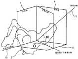
これらの特徴は、図1及び図2に示されており、図1は、傾斜角及び回転角がX線撮影基準系内でどのように定義されているかを示し(傾斜角が「θ」とラベルされ、回転角が「α」とラベルされている)、図2は、傾斜角及び回転角が解剖学的基準系内でどのように定義されているかを示す(傾斜角が「β」とラベルされ、回転角が「γ」とラベルされている)。典型的には、X線撮影基準系において測定して、回転角は、約15〜約20度であってもよく、傾斜角は、約40〜約45度であってもよい。解剖学的基準系において測定して、回転角は、約15〜約20度の範囲内であり、傾斜角は、約40〜約45度の範囲内であることは事実であり得る。 These features are shown in FIGS. 1 and 2, which show how the tilt angle and rotation angle are defined in the X-ray reference frame (the tilt angle is “θ”). FIG. 2 shows how the tilt angle and rotation angle are defined in the anatomical reference system (the tilt angle is “β”). Labeled and the angle of rotation is labeled “γ”). Typically, the rotation angle may be about 15 to about 20 degrees and the tilt angle may be about 40 to about 45 degrees, as measured in an x-ray imaging reference frame. It can be true that the rotation angle is in the range of about 15 to about 20 degrees and the tilt angle is in the range of about 40 to about 45 degrees, as measured in the anatomical reference system.
患者の寛骨臼にカップコンポーネントを埋め込むために外科処置で使用される器具を位置合わせすることが望ましい場合がある。器具は、例えば、カップコンポーネントを受容するために、又は寛骨臼の中にカップコンポーネントを挿入するために寛骨臼を準備する工程で、寛骨臼を修正するために使用され得る。器具は、寛骨臼内又はその周りの骨組織若しくは他の組織を切断するのに使用される切断用器具であってもよい。寛骨臼を修正するために使用され得る器具の例は、切断歯が外側表面上に提供されている部分球状体を有する切削ヘッドを含むリーマーである。リーマーを使用して、寛骨臼を軸の周りで回転させることによって寛骨臼を修正し、切断歯を寛骨臼内部の骨の表面に対して作用させることができる。例えば、ねじ又は他の固定コンポーネントを受容して寛骨臼内の適所にカップコンポーネントを固定するために寛骨臼を穿孔するドリルなどの、寛骨臼を修正する際に使用される他の切断用器具を位置合わせすることが望ましい場合がある。適切な位置合わせを必要とし得る器具の別の例は、切断ガイド、例えば、ねじ若しくは他の固定コンポーネント用の孔を形成するために穿孔工程で使用されるドリル用のガイド、又は鋸を位置合わせして骨を切断するために使用される鋸ガイドなどである。 It may be desirable to align an instrument used in a surgical procedure to implant a cup component into a patient's acetabulum. The instrument can be used to modify the acetabulum, for example, in preparing the acetabulum to receive the cup component or to insert the cup component into the acetabulum. The instrument may be a cutting instrument used to cut bone tissue or other tissue in or around the acetabulum. An example of an instrument that can be used to modify the acetabulum is a reamer that includes a cutting head having a partial sphere with cutting teeth provided on the outer surface. A reamer can be used to modify the acetabulum by rotating the acetabulum about an axis and cause the cutting teeth to act on the surface of the bone inside the acetabulum. Other cuts used in modifying the acetabulum, such as a drill that accepts screws or other fixation components and drills the acetabulum to secure the cup component in place within the acetabulum It may be desirable to align the appliance. Another example of an instrument that may require proper alignment is the alignment of a cutting guide, for example a drill guide used in the drilling process to form a hole for a screw or other fixed component, or a saw. And saw guides used to cut bone.
患者の寛骨臼にカップコンポーネントを位置付けるために使用されるインサータ器具を位置合わせすることが特に望ましい場合がある。インサータ器具は、カップコンポーネントに嵌入力を伝達し、カップコンポーネントが寛骨臼内に適切に着座するのを確実にするために使用され得る。カップコンポーネントは、所定の位置に押し込まれることで寛骨臼内の適所に保持されることができる。次にカップコンポーネントを、ねじなどの締結具を用いて寛骨臼内の適切な位置に保つことができる。カップコンポーネントは、骨セメントを用いて寛骨臼内の適切な位置に保たれてもよい。カップコンポーネントの表面は、寛骨臼内の適所にカップコンポーネントを固定するために、埋め込み後の骨成長に対応することができる多孔質領域を有し得る。 It may be particularly desirable to align the inserter device used to position the cup component on the patient's acetabulum. The inserter instrument can be used to transmit the fit input to the cup component and to ensure that the cup component is properly seated within the acetabulum. The cup component can be held in place within the acetabulum by being pushed into place. The cup component can then be held in place within the acetabulum using fasteners such as screws. The cup component may be kept in place within the acetabulum using bone cement. The surface of the cup component may have a porous region that can accommodate post-implant bone growth to secure the cup component in place within the acetabulum.
寛骨臼カップコンポーネントを位置合わせするために使用することができる器具の例は、国際公開第2011/138327(A)号に開示されている。器具は、一端にカップコンポーネント用のマウントを備えるシャフトを含む。ガイドアームは、シャフトに取り付けられる。ガイドアームは、第1、第2、及び第3の部分を有するように2箇所で折り曲げられており、第1の部分はシャフトに最近接し、第3の部分はガイドアームの自由端を提供する。第1、第2、及び第3の部分は、同一平面上にある。第1の部分と第2の部分との間の角度は約40度であり、第2の部分と第3の部分との間の角度は約90度である。シャフトは、シャフトに固定されたベースを有し、ガイドアームはベース上取り付けられる。ベースは、シャフトに対するガイドアームの配向を調整できるようにする。この器具の使用は、アームの第3の部分が手術台の平面及び患者の長手方向軸と位置合わせされたときにシャフトが所望の寛骨臼軸(例えば、切断工程又はカップコンポーネントを埋め込む工程で寛骨臼が修正されることになる軸である)と位置合わせされるように、アームをシャフトに対して位置付けることを含む。 An example of an instrument that can be used to align an acetabular cup component is disclosed in WO 2011/138327 (A). The instrument includes a shaft with a mount for the cup component at one end. The guide arm is attached to the shaft. The guide arm is folded at two locations to have a first, second and third portion, the first portion being closest to the shaft and the third portion providing the free end of the guide arm. . The first, second, and third portions are on the same plane. The angle between the first part and the second part is about 40 degrees, and the angle between the second part and the third part is about 90 degrees. The shaft has a base fixed to the shaft, and a guide arm is mounted on the base. The base allows adjustment of the orientation of the guide arm relative to the shaft. The use of this instrument is such that when the third part of the arm is aligned with the plane of the operating table and the longitudinal axis of the patient, the shaft is in the desired acetabular axis (eg cutting or embedding cup components). Positioning the arm relative to the shaft such that the acetabulum is aligned with the axis that is to be modified.
国際公開第2011/138327(A)号に開示されている器具の正確な使用は、患者の骨盤が手術台及び患者の長手方向軸に対して適切に位置付けられることに依存する。したがって、患者が側臥位であるとき、脊椎及び骨盤がそれらの解剖学的位置にあること、すなわち、脊椎が手術台の平面と平行である平面にあり、かつ骨盤が屈曲、外転、及び回転のそれぞれにおいて0度の変位で脊椎に対して中央位置にあることが好ましい場合がある。開示した器具の正確な使用はまた、ガイドアームの第3の部分と手術台の平面及び患者の長手方向軸との位置合わせを外科医が評価することを必要とする。 The exact use of the instrument disclosed in WO 2011/138327 (A) depends on the patient's pelvis being properly positioned with respect to the operating table and the patient's longitudinal axis. Thus, when the patient is in a lateral position, the spine and pelvis are in their anatomical position, i.e., the spine is in a plane parallel to the plane of the operating table and the pelvis is bent, abducted, and rotated It may be preferable to be in a central position with respect to the spine with a 0 degree displacement in each of these. Accurate use of the disclosed instrument also requires the surgeon to evaluate the alignment of the third portion of the guide arm with the plane of the operating table and the longitudinal axis of the patient.
股関節置換手術の間、患者の骨盤の位置を正確に制御することが困難な場合がある。このことは、状況によっては、寛骨臼カップコンポーネントの位置決めの誤りにつながり得る。 During hip replacement surgery, it may be difficult to accurately control the position of the patient's pelvis. This can lead to mispositioning of the acetabular cup component in some circumstances.
本発明は、患者の背中のランドマークに対して位置付けられる第1の端部を有するガイドアームと、アームの第2の端部における、切削具又は寛骨臼コンポーネント用のインサータである器具とを使用する、股関節置換手術で使用するための器具アセンブリであって、ガイドアームは、第2の端部から第1の端部に向かって延在する軸を画定し、その軸に対して器具が配向される、器具アセンブリを提供する。 The present invention includes a guide arm having a first end positioned relative to a landmark on a patient's back, and an instrument that is an inserter for a cutting tool or acetabular component at the second end of the arm. An instrument assembly for use in hip replacement surgery, wherein the guide arm defines an axis extending from the second end toward the first end relative to the axis. An instrument assembly is provided that is oriented.
本発明は、したがって、股関節置換手術で使用するための器具アセンブリであって、第1の端部及び第2の端部を有するガイドアームであって、患者の背中のランドマークに対してガイドアームを位置付けるためにマウントを第1の端部に備える、ガイドアームと、患者の寛骨臼を修正するためのガイドアームの第2の端部における又は第2の端部に向かう器具と、を備え、ガイドアームは、第1の端部と第2の端部との間に患者の胴体を収めるためにアーチ状になっており、第1の端部と第2の端部との間に延在する基準軸を画定し、その軸に対して器具が配向される、器具アセンブリを提供する。 The present invention is therefore an instrument assembly for use in hip replacement surgery, a guide arm having a first end and a second end, the guide arm relative to a landmark on a patient's back A guide arm with a mount at the first end for positioning the device, and an instrument at or toward the second end of the guide arm for modifying the patient's acetabulum The guide arm is arched to accommodate the patient's torso between the first end and the second end and extends between the first end and the second end. An instrument assembly is provided in which an existing reference axis is defined and the instrument is oriented relative to the axis.
本発明のアセンブリは、寛骨臼を修正するための器具を解剖学的ランドマークに対して位置合わせすることを可能にする。これにより、他の基準点に対して器具を位置合わせするときに必要となるような、外科処置中に患者の位置及び配向を、特に患者の骨盤の位置及び配向を制御する必要がなくなる又は少なくとも減少する。 The assembly of the present invention allows an instrument for correcting the acetabulum to be aligned with respect to the anatomical landmark. This eliminates the need to control the position and orientation of the patient during the surgical procedure, particularly the position and orientation of the patient's pelvis, as required when aligning the instrument with respect to other reference points. Decrease.
ガイドアームは、概して、第1の端部と第2の端部との間の一部が、端部間に延在する直線に対してオフセットされるように成形される。ガイドアームは、概して、第1の端部と第2の端部との間の一部が、ガイドアームの第1の端部と、ガイドアームの第2の端部における又は第2の端部に向かう点であって、器具がその点においてガイドアームに締結される、点との間に延在する直線に対してオフセットされるように成形される。ガイドアームのオフセット部分は、ガイドアームの第1の端部が患者の背中の組織に接触して、高い頻度で患者の脊椎に近接して位置付けられ、かつガイドアームの第2の端部が患者の寛骨臼の上方に位置付けられ、器具が寛骨臼の方を、また概ね第1の端部の方を向いている状態で、ガイドアームを患者の胴体の周りに取り付けることを可能にし得る。 The guide arm is generally shaped such that a portion between the first end and the second end is offset with respect to a straight line extending between the ends. The guide arm generally has a portion between the first end and the second end, the first end of the guide arm and the second end of the guide arm or the second end. At the point where the instrument is fastened to the guide arm and is offset relative to a straight line extending between the points. The offset portion of the guide arm is frequently positioned proximate to the patient's spine with the first end of the guide arm contacting the patient's back tissue and the second end of the guide arm being the patient. Positioned above the acetabulum and may allow the guide arm to be mounted around the patient's torso with the instrument facing the acetabulum and generally toward the first end. .
ガイドアームは、棒又はさおなどの形状の1つ又は2つ以上の部材によって提供されることがある。そのような部材は、中実断面を有してもよいか、又はそれらの長さの一部若しくは全体に沿って中空であってもよい。しかしながら、ガイドアームは、他の方法で、例えばシートからカットされることによって提供されてもよい。 The guide arm may be provided by one or more members in the shape of a rod or cage. Such members may have a solid cross section or may be hollow along part or all of their length. However, the guide arm may be provided in other ways, for example by being cut from the sheet.
器具を、患者の背中に位置する端部と反対にあるガイドアームの端部において又はその端部に向けて、ガイドアームに対して位置付けることができる。器具は、ガイドアームに接触することができる。器具若しくはガイドアーム又はそれらのそれぞれは、互いに接触しているときに2つの間の相対移動を制限するような方法で成形され得る。器具は、ガイドアームに連結されていてもよい。連結は、ガイドアームに対する器具の位置(位置合わせを含む)を変更することができるようにするものであってもよい。連結は、器具とガイドアームとの間の相対移動を妨げる剛性連結であってもよい。器具は、ガイドアームの反対側の端部から離間した位置でガイドアームと接触していてもよい。例えば、ガイドアームは、第1の端部と第2の端部との間のガイドアームの長さに沿った点において、器具が第2の端部に向かうガイドアームと接するように位置する終端部を含んでもよい。ガイドアームが、第1の端部と第2の端部との間の一部がオフセットされるように成形されている場合、器具と第2の端部との間のガイドアームの終端部は、器具から概ね第1の端部に向かう方向に向くことができる。これにより、患者の解剖学的構造の特徴に対する、具体的には患者の背中上の選択されたランドマーク及び患者の寛骨臼などの患者の骨盤上の特徴に対する、ガイドアームの配向の指標をユーザーに提供することができる。 The instrument can be positioned relative to the guide arm at or toward the end of the guide arm opposite the end located on the patient's back. The instrument can contact the guide arm. The instruments or guide arms or each of them can be shaped in such a way as to limit the relative movement between the two when in contact with each other. The instrument may be coupled to the guide arm. The connection may be such that the position of the instrument relative to the guide arm (including alignment) can be changed. The connection may be a rigid connection that prevents relative movement between the instrument and the guide arm. The instrument may be in contact with the guide arm at a position spaced from the opposite end of the guide arm. For example, the guide arm is located at a point along the length of the guide arm between the first end and the second end so that the instrument is in contact with the guide arm toward the second end. Part may be included. If the guide arm is shaped such that a portion between the first end and the second end is offset, the end of the guide arm between the instrument and the second end is , Generally in the direction from the instrument towards the first end. This provides an indication of the orientation of the guide arm relative to the patient's anatomical features, specifically to the patient's pelvic features such as selected landmarks on the patient's back and the patient's acetabulum. Can be provided to users.
ガイドアームは、患者の胴体を収めることができるようにアーチ状になっており、基準軸が胴体を通るように第1の端部と第2の端部との間に位置付けられる。ガイドアームのアーチ形状は、概ね丸くなっていてよい。アーチ形状は、クランク状部分により提供され得る。アーチ形状は、1つ又は2つ以上の真っ直ぐな部分で構成され得る。例えば、アーチ形状は、基準軸に対して概ね横方向に(必要に応じて垂直に)延在する2つの真っ直ぐな部分、及び基準軸に対してほぼ平行に延在する、2つの横方向の真っ直ぐな部分の間の第3の真っ直ぐな部分を含む、3つの真っ直ぐな部分で構成され得る。ガイドアームは、特に一定の半径により画定される、概ね丸くなった弧を画定する弓状部分を第1の端部と第2の端部との間に有し得る。ガイドアームの弓状部分により画定される弧の角度は、有用には、少なくとも約150度であり得る。ガイドアームの弓状部分は、ガイドアームの端部間に延在する線に沿って延在する(又は延在するように配置され得る)ガイドアームの第1の真っ直ぐな部分と第2の真っ直ぐな部分との間に延在し得る。ガイドアームは、複数の肢部を有するほぼクランク状部分を有し得る。 The guide arm is arched to accommodate the patient's torso and is positioned between the first and second ends so that the reference axis passes through the torso. The arch shape of the guide arm may be generally round. The arch shape can be provided by a crank-like portion. The arch shape may be composed of one or more straight portions. For example, the arch shape may include two straight portions that extend generally transversely (optionally perpendicular) to the reference axis, and two transverse portions that extend substantially parallel to the reference axis. It can be composed of three straight portions, including a third straight portion between the straight portions. The guide arm may have an arcuate portion between the first end and the second end that defines a generally rounded arc, particularly defined by a constant radius. The arc angle defined by the arcuate portion of the guide arm may usefully be at least about 150 degrees. The arcuate portion of the guide arm includes a first straight portion and a second straight portion of the guide arm that extend (or may be arranged to extend) along a line that extends between the ends of the guide arm. It can extend between the various parts. The guide arm may have a generally cranked portion having a plurality of limbs.
任意追加的に、ガイドアームは入れ子式であり得る。ガイドアームが入れ子式であることにより得られる効果は、ガイドアームの入れ子式機能部の配列に依存する。例えば、入れ子式機能部が、ガイドアームの第1の端部と第2の端部との間に延在する線に沿って又は平行に延在するガイドアームの一部で提供されるとき、この機能部により、ガイドアームの長さを調節できるようになる。 Optionally, the guide arm can be telescopic. The effect obtained by the guide arm being nested depends on the arrangement of the nested function parts of the guide arm. For example, when the telescoping feature is provided with a portion of the guide arm extending along or parallel to a line extending between the first end and the second end of the guide arm, With this function unit, the length of the guide arm can be adjusted.
入れ子式機能部が、(特に一定の半径で)弓状であるガイドアームの一部で提供されるとき、この機能部により、アームの第1の終端部と第2の終端部との間の角度を調節できるようになる。このことを使用して、終端部の一方の角度方向を他の終端部に対して変更することができる。ガイドアームの第1の端部が、患者の背中のランドマークに対して位置決めされており、かつ器具が、ガイドアームの第2の端部においてガイドアームに締結される場合(特にガイドアームに対する器具の配向を固定できるように)、ガイドアームの入れ子式部分の調節は、ガイドアームの第2の端部における器具の配向を変更することができる。このことを使用して、例えば患者の特定の解剖学的特徴などの要素、又は外科医の好みを考慮に入れて、器具を使用して寛骨臼が修正される軸の角度を調節することができる。この軸は、本文書において「器具軸」と呼ばれる。この軸は、器具を使用しているとき、寛骨臼を通って延在することになる。寛骨臼から延在する器具軸の配向の選択は、ガイドアームの使用により容易になる。 When the telescoping function is provided with a part of the guide arm that is arcuate (especially with a constant radius), this function causes the arm between the first end and the second end of the arm. The angle can be adjusted. This can be used to change one angular direction of the termination relative to the other termination. When the first end of the guide arm is positioned relative to a landmark on the patient's back and the instrument is fastened to the guide arm at the second end of the guide arm (especially the instrument for the guide arm) Adjustment of the telescoping portion of the guide arm can change the orientation of the instrument at the second end of the guide arm. This can be used to adjust the angle of the axis at which the acetabulum is modified using the instrument, taking into account factors such as the patient's specific anatomical features or the surgeon's preference. it can. This axis is referred to as the “instrument axis” in this document. This shaft will extend through the acetabulum when using the instrument. Selection of the orientation of the instrument shaft extending from the acetabulum is facilitated by the use of a guide arm.
本発明の器具アセンブリは、ガイドアームがガイドアームにより画定される基準軸を外科医に提供するという利点を有する。患者の寛骨臼を修正するのに使用される器具は、この基準軸と位置合わせされてもよく、又はこの基準軸を参照して位置合わせされてもよい。状況によっては、器具を基準軸に対してオフセットさせて位置合わせすることが好ましいことがある。骨盤自体を基準として使用することができるので、アセンブリの使用は、基準面又は軸に対する患者の骨盤の位置又は配向を正確に制御する必要性を低減又は排除することができる。アセンブリの使用はまた、外科医が、器具から離間した基準面又は基準軸に対する器具又はその一部の位置合わせを推定する必要性を低減又は排除することができる。 The instrument assembly of the present invention has the advantage that the guide arm provides the surgeon with a reference axis defined by the guide arm. The instrument used to modify the patient's acetabulum may be aligned with this reference axis or may be aligned with reference to this reference axis. In some situations, it may be preferable to align the instrument with an offset relative to the reference axis. Since the pelvis itself can be used as a reference, the use of the assembly can reduce or eliminate the need to accurately control the position or orientation of the patient's pelvis relative to a reference plane or axis. The use of the assembly can also reduce or eliminate the need for the surgeon to estimate the alignment of the instrument or a portion thereof relative to a reference plane or reference axis spaced from the instrument.
アセンブリを使用するとき、ガイドアームにより画定される基準軸が寛骨臼を通って延在することが好ましい場合がある。基準軸が器具軸に対して角度オフセットされている場合、それらの軸が寛骨臼内の骨の表面の周囲で交差することが好ましい場合がある。 When using the assembly, it may be preferred that the reference axis defined by the guide arm extends through the acetabulum. If the reference axes are angularly offset with respect to the instrument axis, it may be preferable for those axes to intersect around the surface of the bone in the acetabulum.
本発明は、患者の背中の基準点の特定を伴う。術前計画工程中に基準点を特定することができる。基準点は、外科処置中に目視によって位置を特定できるように、マークが付けられてもよい。例えば、基準点は、インクマーカーを使用してマークを付けられてもよい。 The present invention involves the identification of a reference point on the patient's back. A reference point can be identified during the preoperative planning process. The reference point may be marked so that it can be located visually during the surgical procedure. For example, the reference point may be marked using an ink marker.
ガイドアームは、基準点に対して患者の背中の皮膚上に位置し得るマウントを第1の端部に有し得る。例えば、マウントは、アームの第1の端部が基準点にくるように、患者の背中の皮膚に留めることができる。基準点は、寛骨臼カップコンポーネントが位置合わせされるべき軸上にあり得る。基準点は、寛骨臼カップコンポーネントが位置合わせされるべき軸から所定の距離又は角度だけずれる場合がある。基準点は、好ましくは、手を使う患者の診察(つまり触診)を含む処置によって位置決めできるようなものである。基準点は、触診により見つけることができる骨のランドマークを参照して位置決めすることができる。ほとんどの患者で容易に特定できる骨のランドマークの例としては、上後腸骨棘(つまりPSIS点)、胸椎又は腰椎上の特徴部、上方腸骨棘、仙骨及び尾骨が挙げられる。患者の背中の特に有用なランドマークの例としては、PSIS点のうちのどちらか、及びPSIS点間の中点を挙げることができる。これらのランドマークは、ほとんどの患者で容易に見つけることができる。例えば、これらのランドマークは、患者が手術台に座っていて、かつ腰椎を出すように腰をかがめることができるときに、手術前に見つけることができる。このように見つけられたランドマークは、所望の寛骨臼軸(寛骨臼を通って延在する、寛骨臼カップコンポーネントが理想的に位置合わせされ得る軸である)に対する基準位置を探すときに有用であり得る。所望の寛骨臼軸は、患者の背中のランドマークにある基準点を通って延在し得る。基準点は、ランドマークから離間し得る。例えば、基準点は、PSISの間の中間にあってもよく、又はランドマークから患者の上下軸に沿った方向に離間していてもよい。多くの場合、基準点は、患者の上下軸上にあるように、又は患者の脊柱の中心線を通過する矢状面上にあるように、患者の背中の中央であることが好ましい。例えば、患者の術前画像を参照して、又は統計上の解剖学的データを参照して、又は画像及び解剖学的データの両方を参照して、ランドマークに対する基準点の位置を推定してもよい。 The guide arm may have a mount at the first end that may be located on the skin of the patient's back relative to a reference point. For example, the mount can be secured to the skin on the patient's back so that the first end of the arm is at the reference point. The reference point can be on the axis to which the acetabular cup component is to be aligned. The reference point may be offset by a predetermined distance or angle from the axis to which the acetabular cup component is to be aligned. The reference point is preferably such that it can be located by a procedure that includes a medical examination (ie palpation) of a patient using the hand. The reference point can be positioned with reference to bone landmarks that can be found by palpation. Examples of bone landmarks that can be easily identified in most patients include superior posterior iliac spines (ie, PSIS points), features on the thoracic or lumbar vertebrae, superior iliac spines, sacrum and coccyx. Examples of particularly useful landmarks on the patient's back can include any of the PSIS points and the midpoint between the PSIS points. These landmarks are easily found in most patients. For example, these landmarks can be found before surgery when the patient is sitting on the operating table and can bend down to protrude the lumbar spine. The landmarks thus found are when looking for a reference position relative to the desired acetabular axis (the axis that extends through the acetabulum, which is the axis where the acetabular cup component can be ideally aligned) Can be useful to. The desired acetabular axis may extend through a reference point at a landmark on the patient's back. The reference point may be spaced from the landmark. For example, the reference point may be midway between the PSISs or may be spaced from the landmark in a direction along the patient's vertical axis. In many cases, it is preferred that the reference point be in the middle of the patient's back, such as on the patient's vertical axis or on a sagittal plane that passes through the centerline of the patient's spinal column. For example, referring to a patient's preoperative image, referring to statistical anatomical data, or referring to both image and anatomical data, estimating the position of the reference point relative to the landmark Also good.
術前計画工程中に基準点の位置の特定を実行することができる。この基準点の位置の特定は、患者の骨盤の画像、特にX線画像を参照して実行することができる。 The location of the reference point can be performed during the preoperative planning process. The position of the reference point can be specified with reference to an image of the patient's pelvis, particularly an X-ray image.
基準点の位置の推定は、ランドマークからの基準点の所要変位を、患者の骨盤の寸法に関連付けた統計上のデータを使用して実行され得る。例えば、基準点の位置を、前後軸に平行に測定された骨盤の大きさ、又は上下軸に平行に測定された骨盤の大きさ、又はこれらの測定値の両方に関連付けることができる。前後軸に平行に測定された骨盤の大きさを、上後腸骨棘のうちの1つと上前腸骨棘のうちの1つとの間で測定することができる。上下軸に平行に測定された骨盤の大きさを、上後腸骨棘のうちの1つと坐骨結節との間で測定することができる。患者の寛骨臼内の寛骨臼コンポーネントの配向は、傾斜角及び前傾角で特徴付けられる。患者に寛骨臼コンポーネントを埋め込む際に使用するための適切な傾斜角及び前傾角は、患者に埋め込まれることになっているコンポーネントの設計、外科医が使用する予定である処置における工程、並びに、場合によっては、立っているとき及び横になっているときの患者の骨盤の角度に依存して推定され得る。場合によっては、適切な傾斜角及び前傾角は、患者の性別及び民族性、並びに患者の骨盤の大きさなどの要素を考慮することがある。 Estimating the position of the reference point may be performed using statistical data relating the required displacement of the reference point from the landmark to the dimensions of the patient's pelvis. For example, the position of the reference point can be related to the size of the pelvis measured parallel to the anteroposterior axis, the size of the pelvis measured parallel to the vertical axis, or both of these measurements. The size of the pelvis measured parallel to the anteroposterior axis can be measured between one of the upper posterior iliac spines and one of the upper anterior iliac spines. The size of the pelvis, measured parallel to the vertical axis, can be measured between one of the superior posterior iliac spines and the sciatic nodule. The orientation of the acetabular component within the patient's acetabulum is characterized by a tilt angle and a anteversion angle. Appropriate tilt and anteversion for use in implanting an acetabular component in a patient is determined by the design of the component that is to be implanted in the patient, the steps in the procedure that the surgeon intends to use, and if Can be estimated depending on the angle of the patient's pelvis when standing and lying down. In some cases, appropriate tilt and anteversion may take into account factors such as the patient's gender and ethnicity, and the size of the patient's pelvis.
基準点から上下軸に沿ってガイドアームの第1の端部の適切な変位を選択することにより、傾斜角(冠状面に投影された、寛骨臼コンポーネントの軸と患者の長手方向軸との間の角である)を選択する目的で基準点の位置を調節することができる。例えば、約180cmの身長、及び寛骨臼中心から寛骨臼中心まで17.5cmを有する典型的な男性患者の場合、PSIS点間の中間に位置する基準点に対して下位方向に1cmの変位は、約2.3度の傾斜角の増加をもたらす。 By selecting the appropriate displacement of the first end of the guide arm along the vertical axis from the reference point, the angle of inclination (the axis of the acetabular component projected on the coronal plane and the longitudinal axis of the patient The position of the reference point can be adjusted for the purpose of selecting the angle between. For example, for a typical male patient having a height of about 180 cm and 17.5 cm from the center of the acetabulum to the center of the acetabulum, a displacement of 1 cm in the lower direction relative to a reference point located midway between the PSIS points Results in an increase in tilt angle of about 2.3 degrees.
基準点を位置決めするための患者の背中のランドマークの使用は、皮膚と下部の骨組織との間の軟組織の量が少ない領域内に基準点が存在し得るという利点を有する。具体的には、基準点を仙骨領域内の皮膚に位置決めすることができることが想定される。皮膚と仙骨との間の脂肪の量は、肥満の患者でも比較的少ない。仙骨は、基準点にマウントを位置付けるための安定した強固な表面を提供することができる。 The use of the patient's back landmark to locate the reference point has the advantage that the reference point can be in an area where the amount of soft tissue between the skin and the underlying bone tissue is low. Specifically, it is assumed that the reference point can be positioned on the skin in the sacral region. The amount of fat between the skin and the sacrum is relatively low even in obese patients. The sacrum can provide a stable and robust surface for positioning the mount at a reference point.
マウントは、ガイドアームの第1の端部に設けられて、患者の背中の基準点に対して手で適所に保持されるように意図され得る。マウントは、ガイドアームの端面により提供され得る。マウントは、ガイドアームとは別個の部分により提供され得る。ガイドアーム及び別個のマウントを互いに連結することができる。ガイドアーム及び別個のマウントは、必ずしも分離に抵抗するように互いに連結される必要はなく、互いに接触して配置され得るように成形されてもよい。マウントは、特にガイドアームがマウントに対して移動できるとき、外科チームのメンバーによってマウントが把持されるのを容易にするように成形され得る。特にガイドアームがマウントに固定されているとき、ガイドアームを使用してマウントを適所に保持することができる。 The mount may be provided at a first end of the guide arm and intended to be held in place by hand relative to a reference point on the patient's back. The mount can be provided by the end face of the guide arm. The mount may be provided by a separate part from the guide arm. A guide arm and a separate mount can be connected to each other. The guide arm and the separate mount need not be coupled to each other to resist separation, and may be shaped so that they can be placed in contact with each other. The mount can be shaped to facilitate gripping of the mount by members of the surgical team, particularly when the guide arm is movable relative to the mount. The guide arm can be used to hold the mount in place, especially when the guide arm is secured to the mount.
マウントを、外科用ドレープ又はガウン、又は患者の上に位置する他のカバーの外側の患者の背中の適所に位置付けることができる。カバーは、ガイドを保持する人が基準点を見ることができるように、少なくとも基準点の周りを透明にすることができる。上述したように、基準点は、術前計画工程中に特定された後で、その後外科処置中に見つけることができるようにマークを付けられてもよい。 The mount can be positioned in place on the patient's back outside of a surgical drape or gown or other cover located on the patient. The cover can be transparent at least around the reference point so that a person holding the guide can see the reference point. As described above, the reference point may be marked so that it can be found during a surgical procedure after it has been identified during the pre-operative planning process.
マウントが患者の皮膚(又はドレープ、又は患者の皮膚の上に位置する他のカバー)に当接保持されるとき、マウントを、患者の背中で患者の皮膚に安定して着座するように成形することができる。例えば、皮膚に着座することができるほぼ平坦なパッドを有してもよい。マウントとガイドアームの第1の端部との間の連結は、剛性であり得る。マウントとガイドアームの第1の端部との間の連結は、マウントをガイドアームに対して関節運動可能にし得る。 When the mount is held against the patient's skin (or drape, or other cover located on the patient's skin), the mount is shaped to sit stably on the patient's skin on the patient's back. be able to. For example, it may have a substantially flat pad that can be seated on the skin. The connection between the mount and the first end of the guide arm can be rigid. The connection between the mount and the first end of the guide arm may allow the mount to articulate relative to the guide arm.
任意追加的に、マウントは、マウントが適所にあるときに患者の皮膚に接触する表面上に、ある量の接着剤を含む。接着剤は、時として通気可能であることが望ましい場合がある。接着剤は、アレルギー反応の可能性が低くなければならず、皮膚を損傷する可能性を最小限に抑えて皮膚表面から外すことができるべきである。マウントを皮膚に固定するのに使用され得る接着剤の種類として、アクリルポリマー及びシリコーンポリマー、ヒドロコロイド、ハイドロゲル、ゴム系の材料、ポリウレタン、ポリエステル、並びにポリエーテルに基づく材料が挙げられる。適切な接着剤を選択する際に入れられてもよい要素として、粘着度、取り外し易さ、水蒸気透過率、抗菌剤添加物との適合性、及びアレルギー反応のリスクを挙げることができる。アクリル系ポリマーは、それらの低コスト、良好な粘着度、良好な剥離強度、及び良好な凝集力のために、特に好ましい場合がある。好適な材料は、創傷治療の包帯用途における使用から知られている。 Optionally, the mount includes an amount of adhesive on the surface that contacts the patient's skin when the mount is in place. It may sometimes be desirable for the adhesive to be breathable. The adhesive should have a low potential for allergic reactions and should be able to be removed from the skin surface with minimal potential to damage the skin. Types of adhesives that can be used to secure the mount to the skin include acrylic and silicone polymers, hydrocolloids, hydrogels, rubber-based materials, polyurethane, polyester, and polyether based materials. Factors that may be included in selecting an appropriate adhesive can include tackiness, ease of removal, water vapor transmission rate, compatibility with antimicrobial additives, and risk of allergic reactions. Acrylic polymers may be particularly preferred due to their low cost, good adhesion, good peel strength, and good cohesion. Suitable materials are known for use in wound treatment bandage applications.
ある量の接着剤を、外科処置で使用するために供給されるマウントに提供することができる。マウント(及びアセンブリの他のコンポーネント)が、無菌性を保つ適切な包装を用いて無菌状態で提供されることが、処置によっては適切な場合がある。接着剤は、使用のために剥離して接着剤の表面を露出させることができる、接着剤に適用される保護膜を有することができる。 A quantity of adhesive can be provided on a mount that is supplied for use in a surgical procedure. Depending on the procedure, it may be appropriate for the mount (and other components of the assembly) to be provided in a sterile condition using appropriate packaging that maintains sterility. The adhesive can have a protective film applied to the adhesive that can be peeled off for use to expose the surface of the adhesive.
アセンブリは、ガイドアームをマウントに連結するためのコネクタを提供することができる。任意追加的に、ガイドアームは、第1の端部にアームコネクタ構造を有することができ、マウントは、アームコネクタ構造を係合してマウントに対するアームの移動を制限することができるマウントコネクタ構造を有することができる。任意追加的に、ガイドアームは、アーム磁力コネクタ部を有することができ、マウントは、マウント磁力コネクタ部を有することができ、これらはアームとマウントとの間に引力を起こして分離を妨げる。これらの形成部を有する器具アセンブリの特徴は、代理人の参照番号SJB/P213137で本願と共に出願されている英国特許出願に開示されている。その出願で開示される主題は、参照によって本願に組み込まれる。外科処置の準備工程で、患者の身体の解剖学的基準点に対してマウントを固定することができる。次に、その後の工程で、高い頻度でガイドアームにより係合されている器具を外科処置で使用するときに又はその直前に、ガイドアームをマウントと係合することができる。磁力コネクタ部を使用して、ガイドアーム及びマウントのコネクタ構造の位置合わせ及びその後の係合を確実にすることができ、マウントが外科医又は他のユーザーに見えにくいときでも位置合わせ及び連結を容易にする。 The assembly can provide a connector for coupling the guide arm to the mount. Optionally, the guide arm can have an arm connector structure at the first end, and the mount has a mount connector structure that can engage the arm connector structure to limit movement of the arm relative to the mount. Can have. Optionally, the guide arm can have an arm magnetic connector portion, and the mount can have a mount magnetic connector portion that creates an attractive force between the arm and the mount to prevent separation. The features of the instrument assembly having these formations are disclosed in a British patent application filed with the present application under the agent's reference number SJB / P213137. The subject matter disclosed in that application is incorporated herein by reference. During the surgical preparation process, the mount can be fixed relative to the anatomical reference point of the patient's body. Then, in a subsequent step, the guide arm can be engaged with the mount when, or just before, the instrument frequently engaged by the guide arm is used in a surgical procedure. The magnetic connector portion can be used to ensure alignment and subsequent engagement of the guide arm and mount connector structure, facilitating alignment and connection even when the mount is difficult to see by the surgeon or other user To do.
ガイドアームを別個のマウントに連結するためのコネクタは、ガイドアームの第1の端部に複数の固定点を提供することができる。例えば、コネクタは、ガイドアームの第1の端部に固定点の直線配列を少なくとも1つ提供することができる。固定点の配列は、ガイドアームの第1の端部が基準点に対して適切に位置決めされるように、固定点を選択する可能性を外科医に与える。患者の長手方向軸に沿って配置されている固定点の配列は、上述のように、特定の患者の必要条件に適合する所望の寛骨臼軸の傾斜角を選択する可能性を外科医に与える。 A connector for coupling the guide arm to a separate mount can provide a plurality of fixation points at the first end of the guide arm. For example, the connector can provide at least one linear array of fixed points at the first end of the guide arm. The array of fixation points gives the surgeon the possibility to select a fixation point so that the first end of the guide arm is properly positioned relative to the reference point. The array of fixation points located along the patient's longitudinal axis gives the surgeon the possibility to select the desired acetabular axis tilt angle to suit the particular patient's requirements, as described above. .
コネクタ及びガイドアームは、スピゴット及びソケット機能部を含むことができ、スピゴット及びソケットのうちの1つはコネクタにより提供され、スピゴット及びソケットのうちの他方はガイドアームにより提供される。例えば、コネクタは、1つ又は2つ以上のソケットを提供することができ、ガイドアームは、そのソケット(又はソケットのうちの選択された1つ)内に滑りばめであるスピゴットを提供することができる。スピゴットは、挿入方向に位置合わせされている方向以外にソケットに対して移動できないような方法でソケット内に収まることができる。ソケット内へのスピゴットの係合は、したがってコネクタに対するガイドアームの角度方向を画定することができる。 The connector and guide arm can include a spigot and socket feature, one of the spigot and socket being provided by the connector and the other of the spigot and socket being provided by the guide arm. For example, the connector can provide one or more sockets, and the guide arm can provide a spigot that is a sliding fit within that socket (or a selected one of the sockets). it can. The spigot can fit within the socket in such a way that it cannot move relative to the socket other than in a direction aligned with the insertion direction. The engagement of the spigot within the socket can thus define the angular orientation of the guide arm relative to the connector.
コネクタ及びガイドアームは、ボール及びソケットコネクタ機能部を含むことができ、ボール及びソケットのうちの1つはコネクタにより提供され、ボール及びソケットのうちの他方はガイドアームにより提供される。ボールをソケット内に受容させることにより、ガイドアームをコネクタに連結することができる。ボールは、ソケット内に関節接合可能であり得る。 The connector and guide arm can include a ball and socket connector feature, wherein one of the ball and socket is provided by the connector, and the other of the ball and socket is provided by the guide arm. By receiving the ball in the socket, the guide arm can be coupled to the connector. The ball can be articulatable in the socket.
固定点の配列を提供するコネクタコンポーネントを、患者の背中で皮膚に留められるマウントの一部として提供することができる。固定点の配列を提供するコネクタコンポーネントを、ガイドアームの一部として提供することができる。固定点の配列を提供するコネクタコンポーネントを、マウント及びガイドアームのそれぞれから分離している部分として提供することができ、マウント及びガイドアームのそれぞれに連結することができる。マウントから分離しているコネクタコンポーネントを、コネクタ構造及び磁力コネクタコンポーネントを用いてマウントに連結することができる。ガイドアームから分離しているコネクタコンポーネントを、スピゴット及びソケット機能部を用いてガイドアームに連結することができる。 A connector component that provides an array of fixation points can be provided as part of a mount that is secured to the skin on the patient's back. A connector component that provides an array of fixation points can be provided as part of the guide arm. A connector component that provides an array of fixation points can be provided as a separate part from each of the mount and guide arm and can be coupled to each of the mount and guide arm. A connector component that is separate from the mount can be coupled to the mount using a connector structure and a magnetic connector component. A connector component that is separate from the guide arm can be coupled to the guide arm using a spigot and socket feature.
第1の端部と第2の端部との間の一部が、端部間に延在する直線に対してオフセットされるようにガイドアームが成形されている場合、第1の端部と第2の端部との間でガイドアームの長さに沿ったガイドアームの部分が共通平面に位置することが好ましい場合がある。ガイドアームが第1の終端部と第2の終端部との間に弓状部分を有している場合、弓状部分並びに第1の終端部及び第2の終端部は、共通平面に位置することができる。ガイドアームが、ガイドアームの第1の終端部と第2の終端部との間に位置付けられるクランク状部分(複数の肢部で構成される)を有している場合、クランク状部分並びに第1の終端部及び第2の終端部は、共通平面に位置することができる。 If the guide arm is shaped such that a portion between the first end and the second end is offset with respect to a straight line extending between the ends, the first end It may be preferred that the portion of the guide arm along the length of the guide arm between the second end is located in a common plane. When the guide arm has an arcuate portion between the first end portion and the second end portion, the arcuate portion and the first end portion and the second end portion are located in a common plane. be able to. When the guide arm has a crank-like portion (consisting of a plurality of limbs) positioned between the first end portion and the second end portion of the guide arm, the crank-like portion and the first The terminal portion and the second terminal portion may be located on a common plane.
患者の背中に取り付けられることが意図されるマウントの表面は、患者の背中の選択された表面領域に取り付けられるように構成される。マウントが仙骨に取り付けられることになっている場合には、マウントの表面は、高い頻度で本質的に平面となる。 The surface of the mount intended to be attached to the patient's back is configured to be attached to a selected surface area of the patient's back. If the mount is to be attached to a sacrum, the surface of the mount will frequently be essentially flat.
入れ子式弓状部分を含むガイドアームの使用は、ガイドアームの第1の端部における基準点に対する、器具を使用して寛骨臼が修正される軸(器具軸)の配向を、入れ子式弓状部分のガイドアームの長さを適切に調節することによって調節することができるという利点を有する。ガイドアームの長さを調節することの回転角及び傾斜角への影響は、患者の長手方向軸及び冠状面に対するガイドアームの配向(具体的には、第1の端部と第2の端部との間でガイドアームの長さに沿ったガイドアームの部分が共通平面に位置するとき、ガイドアームにより画定される平面の配向)に依存する。ガイドアームにより画定される平面が、ガイドアームの長さについての入れ子式調節の傾斜角に与える影響が少ないか又はないように配置され、その結果、長さの調節が回転角(寛骨臼コンポーネントの軸と冠状面との間の角である)だけを変更することが好ましい場合がある。ガイドアームは、(i)ガイドアームを含む平面と前後軸との間の角度が小さく、例えば20度未満、好ましくは10度未満、特に0±5度であるか、又は(ii)ガイドアームの弓状部分により画定された平面と上下軸との間の角度が傾斜角に近く、例えば約45度である、ように配置されることが好ましい場合がある。 The use of a guide arm that includes a telescoping arcuate causes the orientation of the axis (instrument axis) at which the acetabulum is modified using the instrument with respect to a reference point at the first end of the guide arm, the telescoping arc It has the advantage that it can be adjusted by appropriately adjusting the length of the guide arm of the shaped part. The effect of adjusting the length of the guide arm on the rotation angle and tilt angle is dependent on the patient's longitudinal axis and the orientation of the guide arm relative to the coronal plane (specifically, the first and second ends). Depending on the orientation of the plane defined by the guide arm when the portions of the guide arm along the length of the guide arm are located in a common plane. The plane defined by the guide arm is arranged so that it has little or no effect on the tilt angle of the telescoping adjustment on the length of the guide arm, so that the length adjustment is a rotation angle (acetabular component It may be preferable to change only the angle between the axis of the axis and the coronal plane. The guide arm has (i) a small angle between the plane containing the guide arm and the longitudinal axis, for example less than 20 degrees, preferably less than 10 degrees, in particular 0 ± 5 degrees, or (ii) the guide arm It may be preferred that the angle between the plane defined by the arcuate portion and the vertical axis is close to the tilt angle, for example about 45 degrees, it may be preferred.
ガイドアームは、患者の背中に取り付けられることが意図されるマウントの表面に対して降ろした垂線と患者の胴体の周りに延在するガイドアームの部分により画定される平面との間の角度が、約20度以下、より好ましくは約10度以下、特に約5度以下であるように構成され得る。これは、マウントの表面が冠状面に対して平行であるとき、ガイドアームによって画定される平面は、ガイドアームの使用中に冠状面に対してほぼ垂直であることを意味することになる。 The guide arm has an angle between a normal dropped with respect to the surface of the mount intended to be attached to the patient's back and a plane defined by the portion of the guide arm that extends around the patient's torso, It may be configured to be about 20 degrees or less, more preferably about 10 degrees or less, especially about 5 degrees or less. This means that when the surface of the mount is parallel to the coronal plane, the plane defined by the guide arm is approximately perpendicular to the coronal plane during use of the guide arm.
任意追加的に、患者の胴体の周りに延在するガイドアームの部分は、ほぼ平面である。このことは、基準軸に対する器具軸のオフセット(角度オフセット又は変位又はその2つの組み合わせであり得る)の影響に対する制御を容易にすることができる(例えば、ガイドアームの第2の端部におけるフィッティングが、ガイド軸に対する器具軸のオフセットを導入できるようにするときなど)。オフセットの影響を、患者の胴体の周りに延在するガイドアームの部分により画定された平面を適切に位置合わせすることによって制御することができる。 Optionally, the portion of the guide arm that extends around the patient's torso is substantially planar. This can facilitate control over the effect of the offset of the instrument axis relative to the reference axis (which can be an angular offset or displacement or a combination of the two) (eg, fitting at the second end of the guide arm). For example, to allow the introduction of an instrument shaft offset relative to the guide shaft). The effect of the offset can be controlled by properly aligning the plane defined by the portion of the guide arm that extends around the patient's torso.
器具アセンブリは、解剖学的ランドマークに、又は解剖学的ランドマークを参照して位置合わせされ得る少なくとも1つの位置合わせ標識を含むことができる。任意追加的に、患者の寛骨臼を修正するのに使用される器具上に少なくとも1つの位置合わせ標識を提供することができる。器具アセンブリを、器具軸の周りに回転させて、器具アセンブリを寛骨臼に対して角度的に位置合わせすることができる。例えば、位置合わせ標識が、患者の上前腸骨棘に、又は患者の上前腸骨棘を参照して位置合わせされるときに器具アセンブリが適切に回転して位置付けられるように、位置合わせ標識を位置付けることができる。2つの位置合わせ標識を、器具上に提供して、アセンブリを左股関節又は右股関節の外科処置で使用可能にすることができる。 The instrument assembly can include at least one alignment mark that can be aligned with or with reference to the anatomical landmark. Optionally, at least one alignment mark can be provided on the instrument used to modify the patient's acetabulum. The instrument assembly can be rotated about the instrument axis to angularly align the instrument assembly with respect to the acetabulum. For example, the alignment mark so that the instrument assembly is properly rotated and positioned when the alignment mark is aligned with or with reference to the patient's upper anterior iliac spine. Can be positioned. Two alignment markers can be provided on the instrument to enable the assembly to be used in left or right hip surgical procedures.
ガイドアームの第2の端部において、フィッティングを用いて単一平面内で器具軸の配向を調節できるようにすることが、有利であり得ることが見出された。好ましくは、その平面と器具軸及び上前腸骨棘を含む位置合わせ軸との間の角度は、少なくとも約15度、より好ましくは少なくとも約25度、特に少なくとも約30度、例えば約40〜45度である。好ましくは、器具軸を調節することができる平面と位置合わせ軸との間の角度は、約65度以下、より好ましくは約55度以下、特に約50度以下である。器具は、上前腸骨棘に、又は上前腸骨棘を参照して位置合わせされ得る少なくとも1つの位置合わせ標識を含むことができる。2つの位置合わせ標識を、器具上に提供して、アセンブリを左股関節又は右股関節の外科処置で使用可能にすることができる。2つの位置合わせ標識間の角度は、少なくとも約60度、任意追加的に少なくとも約70度、例えば少なくとも約80度であり得る。2つの位置合わせ標識間の角度は、約110度以下、任意追加的に約100度以下、例えば約95度以下であり得る。 It has been found that it may be advantageous to be able to adjust the orientation of the instrument axis in a single plane using a fitting at the second end of the guide arm. Preferably, the angle between the plane and the alignment axis comprising the instrument axis and the superior anterior iliac spine is at least about 15 degrees, more preferably at least about 25 degrees, especially at least about 30 degrees, such as about 40-45. Degree. Preferably, the angle between the plane on which the instrument axis can be adjusted and the alignment axis is about 65 degrees or less, more preferably about 55 degrees or less, especially about 50 degrees or less. The instrument can include at least one alignment mark that can be aligned with or with reference to the superior anterior iliac spine. Two alignment markers can be provided on the instrument to enable the assembly to be used in left or right hip surgical procedures. The angle between the two alignment marks can be at least about 60 degrees, optionally at least about 70 degrees, for example at least about 80 degrees. The angle between the two alignment marks can be about 110 degrees or less, optionally about 100 degrees or less, such as about 95 degrees or less.
任意追加的に、アセンブリは、器具から器具により画定される軸に対してほぼ横方向に延在する第1の位置合わせ標識と第2の位置合わせ標識とを含むことができ、トラックは、位置合わせ標識間に位置付けられて、トラックと位置合わせ標識のそれぞれとの間の角度は、ほぼ等しい。 Optionally, the assembly can include a first alignment indicator and a second alignment indicator extending from the instrument in a direction generally transverse to an axis defined by the instrument, wherein the track has a position Positioned between the alignment marks, the angles between the track and each of the alignment marks are approximately equal.
高い頻度で、患者の胴体の周りに延在するガイドアームの部分を含む平面と患者の長手方向軸との間の角度は、少なくとも約20度、より好ましくは少なくとも約30度、特に少なくとも約40度、例えば約45度であることが好ましい場合がある。高い頻度で、ガイドアームの部分により画定された平面と患者の長手方向軸との間の角度は、約70度以下、より好ましくは約60度以下、特に約50度以下であることが好ましい場合がある。 Frequently, the angle between the plane containing the portion of the guide arm that extends around the patient's torso and the patient's longitudinal axis is at least about 20 degrees, more preferably at least about 30 degrees, especially at least about 40. It may be preferred that the degree is, for example, about 45 degrees. Frequently, the angle between the plane defined by the portion of the guide arm and the patient's longitudinal axis is preferably about 70 degrees or less, more preferably about 60 degrees or less, especially about 50 degrees or less. There is.
任意追加的に、患者の胴体の周りに延在するガイドアームの弓状部分は、一定の半径を有する経路を画定し、またガイドアームにより画定された弧の角度は、例えば少なくとも約180度、好ましくは少なくとも約185度、例えば約190度である最大角度まで変えることができる。 Optionally, the arcuate portion of the guide arm extending around the patient's torso defines a path having a constant radius, and the angle of the arc defined by the guide arm is at least about 180 degrees, for example, Preferably it can be varied up to a maximum angle of at least about 185 degrees, for example about 190 degrees.
任意追加的に、アセンブリは、ガイドアームの第2の端部における又は第2の端部に向かうフィッティングを含み、器具がそれを通じてガイドアームに直接又は間接的に係合する。フィッティングの一部を、ガイドアーム上に提供することができ、またフィッティングの一部を器具上に提供することができる。 Optionally, the assembly includes a fitting at or towards the second end of the guide arm through which the instrument engages the guide arm directly or indirectly. A part of the fitting can be provided on the guide arm and a part of the fitting can be provided on the instrument.
フィッティングは、ガイドアームの第1の端部と第2の端部との間に延在する線に対して固定されている器具により画定された軸の配向を画定することができる。器具により画定される軸は、概して器具を使用して処置(例えば、成形処置又はプロテーゼコンポーネントの埋め込み)が実行される軸になる。フィッティングを配置して、器具の配向若しくはその位置又は両方を、ガイドアームの第1の端部と第2の端部との間に延在する基準軸に対して調節することを可能にすることができる。このことを使用して、例えば患者の特定の解剖学的特徴などの要素、又は外科医の好みを考慮に入れて、器具を使用して寛骨臼が修正される器具軸の角度を調節することができる。 The fitting can define an axial orientation defined by an instrument that is fixed relative to a line extending between the first and second ends of the guide arm. The axis defined by the instrument is generally the axis on which the instrument is used to perform a procedure (eg, a molding procedure or implantation of a prosthetic component). Placing a fitting to allow the orientation of the instrument or its position or both to be adjusted relative to a reference axis extending between the first end and the second end of the guide arm. Can do. Use this to adjust the angle of the instrument axis at which the acetabulum is modified using the instrument, taking into account factors such as the patient's specific anatomical features or the surgeon's preference Can do.
任意追加的に、ガイドアームの第2の端部における又は第2の端部に向かうフィッティングは、器具をガイドアームの第2の端部に対して移動することを可能にすることができる。器具をガイドアームに対して移動することを可能にするガイドアーム上のフィッティングは、ロック又は移動を制限することができる他の機能を含むことができる。 Optionally, the fitting at or toward the second end of the guide arm may allow the instrument to be moved relative to the second end of the guide arm. The fitting on the guide arm that allows the instrument to move relative to the guide arm can include locking or other features that can limit movement.
任意追加的に、フィッティングは、ガイドアームの第2の端部に対する器具の移動の弓状経路を画定することができる。フィッティングの例は、ガイドアームの第2の端部及び器具のうちの1つに対して固定されているトラックと、ガイドアームの第2の端部及び器具のうちの他方に対して固定されており、弓状トラック内でスライドすることができるスライダと、を含むことができる。トラックは、器具が弧を通ってガイドアームの第2の端部に対して移動することができるように、弓状であり得る。ガイドアームの第2の端部に対する器具の移動は、円形経路に沿うことができる。器具の移動のための円の中心は、寛骨臼の中心にあり得るか、近接し得る。フィッティングによって弧を通る器具の移動が可能になるアセンブリは、器具により画定された軸とガイドアームの第1の端部と第2の端部との間に延在する線との間の角度の指標をユーザーに提供し得る目盛を含むことが好ましい場合がある。目盛をトラック上に提供することができる。アームの第1の端部と第2の端部との間に延在する線は、患者の寛骨臼などの患者の骨盤上の患者の背中の特徴部上の選択されたランドマークの間に延在する基準軸の指標を外科医に提供することができる。目盛は、次に基準軸に対する器具の角度オフセットについての指標を外科医に提供することができる。上述のように、1つ又は2つ以上の位置合わせ標識を使用して、器具がガイドアームの第2の端部に対して移動することができる平面を配向することができる。フィッティングは、トラックに対するスライダの移動を妨げることができるロックを含むことができる。例えば、2枚の平行な平板によってトラックを提供することができ、またスライダは、平板の間に延在するねじ付きシャフトを含むことができる。ねじ付きシャフト上に、平板に対してしっかり締めることができるロックナットを提供することができる。 Optionally, the fitting can define an arcuate path of movement of the instrument relative to the second end of the guide arm. An example of a fitting is a track that is fixed to one of the second end of the guide arm and the instrument and a second end of the guide arm and the other of the instrument. And a slider that can slide within the arcuate track. The track may be arcuate so that the instrument can move through the arc relative to the second end of the guide arm. The movement of the instrument relative to the second end of the guide arm can follow a circular path. The center of the circle for instrument movement can be at or near the center of the acetabulum. The assembly that allows movement of the instrument through the arc by fitting is an angle between the axis defined by the instrument and a line extending between the first end and the second end of the guide arm. It may be preferable to include a scale that can provide the indicator to the user. A scale can be provided on the track. The line extending between the first and second ends of the arm is between selected landmarks on the patient's back feature on the patient's pelvis, such as the patient's acetabulum. A reference axis indicator extending to the surgeon can be provided to the surgeon. The scale can then provide the surgeon with an indication of the instrument's angular offset relative to the reference axis. As described above, one or more alignment markers can be used to orient a plane in which the instrument can move relative to the second end of the guide arm. The fitting can include a lock that can prevent movement of the slider relative to the track. For example, the track can be provided by two parallel flat plates, and the slider can include a threaded shaft extending between the flat plates. A lock nut can be provided on the threaded shaft that can be tightened against the flat plate.
フィッティングは、フィッティングの一部に歯付きラックを、ラックの歯に対しスライドさせることができる弾性的に変形可能な先端をフィッティングの別の部分に付けた状態で含んでよく、歯は、ラックに対し分離している先端の位置の配列、及びしたがって他のフィッティング部に対するフィッティング部の1つの配列を画定する。 The fitting may include a toothed rack on one part of the fitting with an elastically deformable tip attached to another part of the fitting that can be slid relative to the teeth on the rack. An array of tip positions separated from each other, and thus one array of fitting parts relative to other fitting parts, is defined.
フィッティングは、器具軸(器具を使用して寛骨臼が修正される軸である)が概してガイドアームの第2の端部におけるフィッティングからガイドアームの第1の端部におけるマウントまで延在するように器具を配置することができる。例えばガイドアームが入れ子式弓状部分を有し、かつアームの長さが入れ子式に調節されて回転角の調節を提供する場合のように、器具軸は、第2の端部におけるフィッティングから、ガイドアームの第1の端部においてマウントからずれる点に向かって延在し得る。フィッティングは、ガイドアームに対する器具の移動を、ガイドアームにより画定される軸に沿った移動に制限することができる。 The fitting is such that the instrument shaft (the axis on which the acetabulum is modified using the instrument) generally extends from the fitting at the second end of the guide arm to the mount at the first end of the guide arm. An instrument can be placed on the instrument. The instrument shaft can be removed from the fitting at the second end, for example when the guide arm has a telescoping arc and the length of the arm is telescopically adjusted to provide rotation angle adjustment. It may extend towards a point deviating from the mount at the first end of the guide arm. The fitting can limit the movement of the instrument relative to the guide arm to movement along an axis defined by the guide arm.
ガイドアームの第2の端部における又は第2の端部に向かうフィッティングを、器具を使用しているときに患者の寛骨臼の内外に、寛骨臼に向かって及びこれから離れて器具をスライドさせることを可能にするように配置することができる。このことは、カラー及び細長いシャフトを含むフィッティングを使用して実現することができる。カラー及び細長いシャフトのうちの一方は、ガイドアームの第2の端部に又は第2の端部に向かって提供され、器具は、カラー及び細長いシャフトの他方を含むか又はそこに直接若しくは間接的に取り付けられる。シャフトは、シャフトに対しスライドすることができる。高い頻度で、シャフトは、ガイドアームの第1の端部と第2の端部との間に延在する軸に沿って方向付けられるように配置されることになる。 Slide the instrument into and out of the patient's acetabulum, toward and away from the acetabulum when using the instrument, with a fitting at or toward the second end of the guide arm It can be arranged to make it possible. This can be accomplished using a fitting that includes a collar and an elongated shaft. One of the collar and the elongate shaft is provided at or toward the second end of the guide arm and the instrument includes or directly or indirectly includes the other of the collar and the elongate shaft. Attached to. The shaft can slide relative to the shaft. Frequently, the shaft will be arranged to be oriented along an axis that extends between the first and second ends of the guide arm.
ガイドアームの第2の端部における又は第2の端部に向かうフィッティングは、ガイドアーム軸(ガイドアームの第1の端部と第2の端部との間に延在する)に対する器具の配向若しくは位置又は配向及び位置のそれぞれを調節することを可能にすることができることが好ましい場合がある。器具軸(例えば、寛骨臼カップが成形される、又はカップコンポーネントが埋め込まれる)は、ガイドアーム軸と一致することができる。しかしながら、ガイドアーム軸に対する器具の配向を調節する可能性は、特定の処置の必要条件に適合するように所望される場合、外科医がガイドアーム軸に対する器具軸の位置合わせを調節できるようにする。外科医は、調節の別の態様の代わりに又はそれに加えて、そのような調節に頼ることができる。例えば、外科医は、回転角を調節するためにフィッティングで調節を行うことによって、弓状ガイドアームの長さの調節の代わりに又はそれに加えて器具の配向の調節に頼ることができる。フィッティングでの調節による器具の配向の調節は、ガイドアームを入れ子式に調節することができないときに特に有用であり得る。 The fitting at or toward the second end of the guide arm is the orientation of the instrument relative to the guide arm axis (extending between the first and second ends of the guide arm) Or it may be preferable to be able to adjust each of the position or orientation and position. The instrument axis (eg, the acetabular cup is molded or the cup component is embedded) can coincide with the guide arm axis. However, the possibility of adjusting the orientation of the instrument relative to the guide arm axis allows the surgeon to adjust the alignment of the instrument axis relative to the guide arm axis if desired to meet the particular procedure requirements. The surgeon may rely on such adjustment instead of or in addition to another aspect of adjustment. For example, the surgeon can rely on adjusting the orientation of the instrument instead of or in addition to adjusting the length of the arcuate guide arm by making adjustments at the fitting to adjust the angle of rotation. Adjusting the orientation of the instrument by adjusting the fitting may be particularly useful when the guide arm cannot be telescopically adjusted.
フィッティングは、フィッティングに対し固定される配向で器具を係合することができるつめを提供することができる。つめは、片側に開口していて、器具をつめ内部に位置付けることを可能にすることができる。つめは、器具の長さに沿って離間した点及び器具の周辺部の周りの離間した点で器具を係合することができる内側表面を有することができる。好ましくは、つめの内側表面の構成は、器具が3個以上の離間した点で内側表面に接するようになることが求められる。器具が3個(以上)の点でつめの内側表面と接触しているとき、器具は、つめに対して安定した位置にあるはずである。好ましくは、つめは、器具に沿って離間した点で器具と接することができる2つのつめ部材を含む。つめ部材のそれぞれは、器具の周辺部の周りの離間した点で器具と接することができる。好ましくは、つめ部材のそれぞれは、片側に開口しており、器具をつめ部材の1つ又は両方の内外にスライドすることを可能にする。つめ部材の内側表面は、つめの長さに沿って見たときにほぼU型又はほぼV字型であり得る。 The fitting can provide a pawl that can engage the instrument in an orientation that is fixed relative to the fitting. The pawl can be open on one side and allow the instrument to be positioned inside the pawl. The pawl can have an inner surface that can engage the instrument at spaced points along the length of the instrument and at spaced points around the periphery of the instrument. Preferably, the configuration of the inner surface of the pawl is required so that the device comes into contact with the inner surface at three or more spaced points. When the instrument is in contact with the inner surface of the pawl at three (or more) points, the instrument should be in a stable position relative to the pawl. Preferably, the pawl includes two pawl members that can contact the instrument at points spaced along the instrument. Each of the pawl members can contact the instrument at spaced points around the periphery of the instrument. Preferably, each of the pawl members is open on one side to allow the instrument to slide in and out of one or both pawl members. The inner surface of the pawl member can be generally U-shaped or substantially V-shaped when viewed along the length of the pawl.
器具は、ガイドアームの第2の端部においてフィッティングによって係合されるシャフトを有することができる。シャフトは、フィッティングに対して回転することができるように円形断面を有することができる。 The instrument can have a shaft engaged by fitting at the second end of the guide arm. The shaft can have a circular cross section so that it can rotate relative to the fitting.
アセンブリは、ガイドアームの第2の端部における又は第2の端部に向かう配向機能部を含むことができる。配向機能部を使用して、ガイドアームをガイドアーム軸(ガイドアームの第1の端部と第2の端部との間に延在する)の周りに回転して配向することができる。このことは、器具を配向するとき、特に器具の配向がガイドアーム軸に対してオフセットされるとき、外科医を支援することができる。配向機能部の例は、概ねガイドアームの第2の端部における又は第2の端部に向かうガイドアームに締結される配向アームである。配向アームを、ガイドアームに直接又は間接的に(例えば、ガイドアーム上のフィッティングに)締結することができる。ガイドアームが適切に配置されると、配向アームが適切な解剖学的ランドマークの方へ向けられるように、配向アームを位置付けることができる。例えば、ガイドアームの基準配向を提供するために、配向アームが上前腸骨棘(ASIS)(特に処置が実行されている寛骨臼と患者の同じ側にあるもの)の方に向けられるように配置されることが適切である場合がある。このことは、ガイドアームを配向する際に多くの患者で容易に認識され、位置決めされる、かつ良好な水準の精度を提供する利点を有する。アセンブリが配向機能部を使用して配向されたときに、ガイド軸と器具軸との間の角度を調節すると、前傾角の調節と傾斜角の調節との間に所定の関係を有して、前傾角若しくは傾斜角、又は両方の角度の調節をもたらすことができる。 The assembly can include an orientation feature at or toward the second end of the guide arm. Using the orientation feature, the guide arm can be rotated and oriented about the guide arm axis (which extends between the first and second ends of the guide arm). This can assist the surgeon when orienting the instrument, particularly when the instrument orientation is offset relative to the guide arm axis. An example of an orientation feature is an orientation arm that is fastened to a guide arm generally at or toward the second end of the guide arm. The orientation arm can be fastened directly or indirectly to the guide arm (eg, to a fitting on the guide arm). When the guide arm is properly positioned, the orientation arm can be positioned so that the orientation arm is directed toward the appropriate anatomical landmark. For example, to provide a reference orientation for the guide arm, the orientation arm is directed toward the superior anterior iliac spine (ASIS), particularly on the same side of the patient as the acetabulum where the procedure is being performed. It may be appropriate to be placed in This has the advantage of being easily recognized and positioned by many patients in orienting the guide arm and providing a good level of accuracy. When the assembly is oriented using the orientation feature, adjusting the angle between the guide axis and the instrument axis has a predetermined relationship between the forward tilt angle adjustment and the tilt angle adjustment; Adjustment of the forward tilt angle or tilt angle, or both angles can be provided.
器具は、ガイドアームが器具の一部になるようにガイドアームに強固に締結され得ることが想定される。この配置は、ガイドアームにより画定される軸に対する器具軸の配向に対する高水準の制御を提供するという利点を有することになる。 It is envisioned that the instrument can be securely fastened to the guide arm such that the guide arm is part of the instrument. This arrangement will have the advantage of providing a high level of control over the orientation of the instrument axis relative to the axis defined by the guide arm.
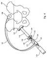
器具は、切削具であり得る。アセンブリで使用され得る切削具の例は、切断歯が外側表面上に設けられている部分球状体を有する切削ヘッドを含むリーマーである。リーマーを使用して、寛骨臼を軸の周りで回転させることによって寛骨臼を修正し、切断歯を寛骨臼内部の骨の表面に対して作用させることができる。切削ヘッドを手で操作して、寛骨臼を切ることができる。切削ヘッドを、電動駆動ユニットを使用して操作することができる。リーマーは、概してシャフトがガイドアームの第2の端部においてフィッティングにより係合された状態でシャフト上に取り付けられることになる。 The instrument can be a cutting tool. An example of a cutting tool that may be used in the assembly is a reamer that includes a cutting head having a partial sphere with cutting teeth provided on the outer surface. A reamer can be used to modify the acetabulum by rotating the acetabulum about an axis and cause the cutting teeth to act on the surface of the bone inside the acetabulum. The acetabulum can be cut by manually operating the cutting head. The cutting head can be operated using an electric drive unit. The reamer will generally be mounted on the shaft with the shaft engaged by fitting at the second end of the guide arm.
切削具の別の例は、ドリルである。 Another example of a cutting tool is a drill.
器具は、寛骨臼カップコンポーネント用のインサータであり得る。器具は、それを通じて嵌入力を寛骨臼カップコンポーネントに加えることができる衝突体であり得る。 The instrument can be an inserter for an acetabular cup component. The instrument can be an impactor through which a fitting input can be applied to the acetabular cup component.
本発明はまた、股関節置換手術で使用するための器具アセンブリであって、
ガイドアセンブリであって、基準部であって、患者の背中上のランドマークに対して基準部を位置決めするためのマウントを有する、基準部と、ガイド部と、を含み、基準部及びガイド部が、それらの間に延在する基準軸を画定する、ガイドアセンブリと、
患者の寛骨臼を修正するための器具であって、器具を使用しているとき、患者の寛骨臼を通って延在する軸を画定し、ガイド部に直接又は間接的に取り付けられる、器具と、を備え、
器具を、ガイド部に対して移動することで、器具軸を基準軸に対して調節することができる、器具アセンブリを提供する。The present invention also provides an instrument assembly for use in hip replacement surgery,
A guide assembly comprising a reference portion having a mount for positioning the reference portion relative to a landmark on the patient's back, and a guide portion, wherein the reference portion and the guide portion are A guide assembly defining a reference axis extending therebetween,
An instrument for modifying a patient's acetabulum, wherein when using the instrument, an axis extending through the patient's acetabulum is defined and attached directly or indirectly to the guide; An instrument, and
An instrument assembly is provided in which the instrument axis can be adjusted relative to a reference axis by moving the instrument relative to the guide.
上述される本発明の器具アセンブリの任意の形成部を、この器具アセンブリで使用することができる。例を下に提示する。 Any formation of the inventive instrument assembly described above can be used in the instrument assembly. An example is given below.
任意追加的に、ガイドアームの両端において、又は両端に向かって、基準部及びガイド部が提供され、ガイドアームは、基準部とガイド部との間に患者の胴体を収めるためにアーチ状になっている。 Optionally, a reference portion and a guide portion are provided at or toward both ends of the guide arm, the guide arm being arcuate to fit the patient's torso between the reference portion and the guide portion. ing.
任意追加的に、器具アセンブリはフィッティングを含み、器具がそれを通じてガイド部に直接又は間接的に係合し、フィッティングは、基準軸に対する器具の配向を調節できるようにする。 Optionally, the instrument assembly includes a fitting through which the instrument engages directly or indirectly with the guide, allowing the fitting to adjust the orientation of the instrument relative to the reference axis.
任意追加的に、フィッティングは、ガイド部に対する器具の移動の弓状経路を画定する。 Optionally, the fitting defines an arcuate path of movement of the instrument relative to the guide.
任意追加的に、フィッティングは、ガイドアームの第2の端部及び器具のうちの1つに対して固定されているトラックと、ガイドアームの第2の端部及び器具のうちの他方に対して固定されており、弓状トラック内でスライドすることができるスライダと、を含む。 Optionally, the fitting is for a track fixed to one of the second end of the guide arm and the instrument and to the other of the second end of the guide arm and the instrument. And a slider that is fixed and capable of sliding in an arcuate track.
任意追加的に、器具アセンブリは、器具から器具により画定される軸に対してほぼ横方向に延在する第1の位置合わせ標識と第2の位置合わせ標識とを含み、トラックは、位置合わせ標識間に位置付けられて、トラックと位置合わせ標識のそれぞれとの間の角度は、ほぼ等しい。 Optionally, the instrument assembly includes a first alignment indicator and a second alignment indicator extending from the instrument in a direction generally transverse to an axis defined by the instrument, and the track includes the alignment indicator. Positioned in between, the angles between the track and each of the alignment marks are approximately equal.
任意追加的に、マウントは、上述される形成部を有し得る。 Optionally, the mount may have the formation described above.
本発明はまた、股関節置換手術で使用するための器具アセンブリであって、
ガイドアセンブリであって、基準部であって、患者の背中上のランドマークに対して基準部を位置決めするためのマウントを有する基準部と、ガイド部と、を含み、基準部及びガイド部が、それらの間に延在する基準軸を画定する、ガイドアセンブリと、
患者の寛骨臼を修正するための器具であって、器具を使用しているとき、寛骨臼を通って延在する軸を画定し、ガイド部に直接又は間接的に取り付けられる、器具と、を備え、
ガイドアームの両端において、又は両端に向かって、基準部及びガイド部が提供され、ガイドアームが、基準部とガイド部との間に患者の胴体を収めるためにアーチ状になっており、ガイドアームの長さが、ガイド部に対する器具の配向を変化させるように調整可能である、器具アセンブリを提供する。The present invention also provides an instrument assembly for use in hip replacement surgery,
A guide assembly, comprising: a reference portion having a mount for positioning the reference portion relative to a landmark on the patient's back; and a guide portion, wherein the reference portion and the guide portion are A guide assembly defining a reference axis extending therebetween;
An instrument for modifying a patient's acetabulum, wherein the instrument defines an axis extending through the acetabulum and is attached directly or indirectly to a guide portion when the instrument is in use; With
A reference portion and a guide portion are provided at or toward both ends of the guide arm, and the guide arm is arched to fit the patient's torso between the reference portion and the guide portion. Provides an instrument assembly whose length is adjustable to change the orientation of the instrument relative to the guide.
上述される本発明の器具アセンブリの任意の形成部を、この器具アセンブリで使用することができる。例を下に提示する。 Any formation of the inventive instrument assembly described above can be used in the instrument assembly. An example is given below.
任意追加的に、マウントは、上述される形成部を有し得る。 Optionally, the mount may have the formation described above.
任意追加的に、ガイドアームは、上述されるように、入れ子式である又は弓状である又は両方であるなどの形成部を有し得る。 Optionally, the guide arm may have a formation, such as being telescoping or arcuate or both, as described above.
本発明はまた、器具アセンブリのコンポーネントと上記で呼ばれる、股関節置換手術で使用するための器具を提供する。したがって、本発明は、股関節置換手術で使用するための器具であって、第1の端部と第2の端部とを有するガイドアームであって、患者の背中のランドマークに対してガイドアームを位置付けるためにマウントを第1の端部に備える、ガイドアームと、患者の寛骨臼を修正するために使用され得る器具用のガイドアームの第2の端部における又は第2の端部に向かうフィッティングと、を含み、ガイドアームは、その第1の端部と第2の端部との間に患者の胴体を収めるためにアーチ状になっており、その第1の端部と第2の端部との間に延在する基準軸を画定し、その軸に対して器具が配向される、器具を提供する。 The present invention also provides an instrument for use in hip replacement surgery, referred to above as a component of the instrument assembly. Accordingly, the present invention is an instrument for use in hip replacement surgery, a guide arm having a first end and a second end, the guide arm against a landmark on the patient's back At the second end or at the second end of the guide arm and instrument guide arm that may be used to modify the patient's acetabulum, with a mount at the first end to position the The guide arm is arcuate to fit the patient's torso between its first and second ends, the first end and the second An instrument is defined in which a reference axis extending between the ends of the instrument is defined and the instrument is oriented relative to the axis.
本発明はまた、股関節置換手術で使用するための器具であって、
a.基準部であって、患者の背中のランドマークに対して基準部を位置決めするためのマウントを有する、基準部と、ガイド部であって、基準部及びガイド部が、それらの間に延在する基準軸を画定する、ガイド部と、
b.患者の寛骨臼を修正するために使用され得る器具を係合するためのフィッティングであって、器具は、器具を使用しているとき、患者の寛骨臼を通って延在する軸を画定し、ガイド部に直接又は間接的に取り付けられる、フィッティングと、を備え、
フィッティングが、器具をガイド部に対して移動できるようにすることで、器具軸を基準軸に対して調節することができる、ガイドアセンブリを備える器具を提供する。The present invention is also an instrument for use in hip replacement surgery,
a. A reference portion having a mount for positioning the reference portion relative to a landmark on the patient's back, and a guide portion, the reference portion and the guide portion extending therebetween A guide portion defining a reference axis;
b. A fitting for engaging an instrument that can be used to modify a patient's acetabulum, the instrument defining an axis extending through the patient's acetabulum when using the instrument And a fitting attached directly or indirectly to the guide part,
An instrument is provided with a guide assembly that allows the instrument to move relative to a reference axis by allowing the instrument to move relative to the guide.
本発明はまた、股関節置換手術で使用するための器具であって、
a.基準部であって、患者の背中上のランドマークに対して基準部を位置決めするためのマウントを有する、基準部と、
b.患者の寛骨臼を修正するために使用され得る器具を係合するためのフィッティングを含むガイド部であって、基準部及びガイド部が、それらの間に延在する基準軸を画定する、ガイド部と、を備え、
ガイドアームの両端において、又は両端に向かって、基準部及びガイド部が提供され、ガイドアームが、基準部とガイド部との間に患者の胴体を収めるためにアーチ状になっており、ガイドアームの長さが、ガイド部に対する器具の配向を変化させるように調整可能である、ガイドアセンブリを備える器具も提供する。The present invention is also an instrument for use in hip replacement surgery,
a. A reference portion having a mount for positioning the reference portion relative to a landmark on the patient's back;
b. A guide portion including a fitting for engaging an instrument that can be used to modify a patient's acetabulum, the reference portion and the guide portion defining a reference axis extending therebetween. And comprising
A reference portion and a guide portion are provided at or toward both ends of the guide arm, and the guide arm is arched to fit the patient's torso between the reference portion and the guide portion. Also provided is an instrument comprising a guide assembly, the length of which can be adjusted to change the orientation of the instrument relative to the guide.
器具アセンブリのその他のコンポーネントなしで提供される器具は、器具アセンブリとの関連において上述された器具の形成部のいずれかを有してもよい。 Instruments provided without other components of the instrument assembly may have any of the instrument formations described above in connection with the instrument assembly.
本発明はまた、股関節置換手術において患者の寛骨臼で実行するための外科的方法であって、
a.患者の背中で骨のランドマークを見つけることと、
b.骨のランドマークを参照して患者の背中で基準点を位置決めすることと、
c.患者の寛骨臼を通って基準点まで延在する基準軸を位置決めすることと、
d.基準軸に、又は基準軸を参照して位置合わせされる器具を使用して寛骨臼を修正することと、を含む、方法も提供する。The present invention also provides a surgical method for performing on a patient's acetabulum in hip replacement surgery comprising:
a. Finding bone landmarks on the patient's back,
b. Positioning a reference point on the patient's back with reference to the bone landmarks;
c. Positioning a reference axis extending through the patient's acetabulum to a reference point;
d. The method also includes modifying the acetabulum using an instrument that is aligned with or with reference to the reference axis.
第1の見つける工程で見つけられる骨のランドマークの例は、上後腸骨棘である。第1の見つける工程が、上後腸骨棘の両方を見つけることを含み、外科的方法が、基準点を上後腸骨棘間の中途に位置決めすることを含むことが好ましい場合がある。方法は、骨のランドマーク(又は複数の骨のランドマーク)に対する基準点のオフセットを組み込むことを含み得る。オフセットの距離、又は方向、又は距離及び方向のそれぞれを変えることができる。これらの変数に影響を与え得る要素としては、患者の性別及び民族性、並びに患者の骨盤の大きさ及び他の解剖学的特徴、患者の寛骨臼に埋め込まれることになるカップコンポーネントの設計、及び外科医の選択が挙げられ得る。 An example of a bone landmark found in the first finding step is the superior posterior iliac spine. It may be preferred that the first finding step includes finding both superior posterior iliac spines and the surgical method includes positioning a reference point midway between the superior posterior iliac spines. The method may include incorporating a reference point offset relative to the bone landmark (or multiple bone landmarks). The offset distance, or direction, or each of the distance and direction can be varied. Factors that can affect these variables include the patient's gender and ethnicity, as well as the size and other anatomical characteristics of the patient's pelvis, the design of the cup component that will be implanted in the patient's acetabulum, And the choice of the surgeon.
外科用器具は、次に基準軸を画定するのに使用され得る基準点において、患者の背中の皮膚に位置付けられ得る。寛骨臼を修正する工程は、切断用器具を使用することを含み得る。寛骨臼を修正する工程は、カップコンポーネントを患者の寛骨臼に埋め込むことを含み得る。修正工程は、基準軸に位置合わせされた器具を使用して実行され得る。修正工程は、基準軸からオフセットされた器具を使用して実行され得る。 The surgical instrument can then be positioned on the skin of the patient's back at a reference point that can be used to define a reference axis. The step of modifying the acetabulum may include using a cutting instrument. The step of modifying the acetabulum may include implanting a cup component into the patient's acetabulum. The correction process can be performed using an instrument aligned with the reference axis. The correction process may be performed using an instrument that is offset from the reference axis.
基準軸は、基準点に位置付けられた第1の端部を有するガイドアームを使用して位置決めされ得る。方法は、例えば、接着剤を使用して、基準点で患者の背中の皮膚にマウントを位置付けることを含み得る。ガイドアームをマウントに締結することができる。 The reference axis can be positioned using a guide arm having a first end positioned at the reference point. The method may include positioning the mount on the skin of the patient's back at a reference point using, for example, an adhesive. The guide arm can be fastened to the mount.
この方法は、基準軸に対して器具の配向を調節する工程を含み得る。器具の配向を調節できるようにするフィッティングを含むアセンブリを使用して、この方法を実行することができる。調節は、弧を通って基準軸に対して器具を移動させることを伴い得る。基準軸に対する器具の移動は、円形経路に沿うことができる。器具の移動のための円の中心を、患者の背中の基準点にすることができる。器具の移動のための円の中心は、寛骨臼の中心にあり得るか、又はより好ましくは近接し得る。フィッティングによって弧を通る器具の移動が可能になるアセンブリは、器具により画定された軸と基準軸との間の角度の指標をユーザーに提供し得る目盛を含むことが好ましい場合がある。目盛は、次に基準軸に対する器具の角度オフセットについて外科医に指標を提供することができる。 The method can include adjusting the orientation of the instrument relative to a reference axis. The method can be performed using an assembly that includes a fitting that allows the orientation of the instrument to be adjusted. The adjustment may involve moving the instrument relative to the reference axis through the arc. The movement of the instrument relative to the reference axis can be along a circular path. The center of the circle for instrument movement can be the reference point on the patient's back. The center of the circle for instrument movement may be at the center of the acetabulum, or more preferably close. An assembly that allows movement of the instrument through the arc by fitting may preferably include a scale that may provide the user with an indication of the angle between the axis defined by the instrument and the reference axis. The scale can then provide an indication to the surgeon about the angular offset of the instrument relative to the reference axis.
方法は、骨のランドマークに対してガイド器具の配向器具を位置合わせすることによって、ガイド器具を基準軸の周りに回転して位置決めする工程を含むことができる。適切な骨のランドマークの例は、上前腸骨棘、特に処置が実行されている寛骨臼と患者の同じ側にあるものである。 The method can include rotating and positioning the guide instrument about a reference axis by aligning the guide instrument orientation instrument with respect to the bone landmark. Examples of suitable bone landmarks are those on the same side of the patient as the superior anterior iliac spine, particularly the acetabulum being treated.
本発明を、添付の図面を参照して例示のために説明する。
図面を参照すると、図1及び図2は、寛骨臼の中央に位置付けられた矢状面、横面及び冠状面4、6、8、並びにまた患者の長手方向軸10の表示と共に患者の骨盤2を示す。図1及び図2はまた、寛骨臼ソケットの幾何学中心から出ている解剖学的寛骨臼軸12も示している。 Referring to the drawings, FIGS. 1 and 2 show the patient's pelvis with a representation of the sagittal, transverse and
図1は、傾斜角及び前傾角がX線撮影基準系においてどのように規定されるのかを示す。この系は、術前計画に使用され、かつ処置の成功を手術後に測定するために使用されるX線から得た測定値に依存する。X線撮影の傾斜角(θ)は、患者の長手方向軸10と冠状面における解剖学的寛骨臼軸12の投影との間の角度として定義され、X線撮影の前傾角(α)は、解剖学的寛骨臼軸と冠状面との間の角度である。 FIG. 1 shows how the tilt angle and forward tilt angle are defined in the X-ray imaging reference system. This system relies on measurements taken from x-rays used for preoperative planning and used to measure the success of the procedure after surgery. The radiographic tilt angle (θ) is defined as the angle between the patient's
図2は、傾斜角及び前傾角が解剖学的基準系においてどのように規定されるのかを示す。この系は、解剖学的な傾斜角(β)を、解剖学的寛骨臼軸12と患者の長手方向軸10との間の角度として、解剖学的前傾角(γ)を、横断面に投影された寛骨臼軸と横軸との間の角度として定義する。 FIG. 2 shows how the tilt angle and anteversion angle are defined in the anatomical reference system. This system uses the anatomical tilt angle (β) as the angle between the
多数の患者にとって、X線撮影基準系を使用した寛骨臼カップコンポーネントの適切な傾斜角は、約40〜約50度、特に約40度〜約45度であり、また適切な前傾角は、約12度〜約25度、特に約15〜約25度であることが頻繁にある。 For many patients, a suitable tilt angle of the acetabular cup component using the radiographic reference system is about 40 to about 50 degrees, especially about 40 degrees to about 45 degrees, and a suitable anteversion angle is Frequently it is about 12 degrees to about 25 degrees, especially about 15 to about 25 degrees.
特定の患者の外科処置に適切である回転角及び傾斜角は、患者に埋め込まれることになっているコンポーネントの設計、外科医が使用する予定である処置における工程、並びに、場合によっては、立っているとき及び横になっているときの患者の骨盤の角度を含むいくつかの要因に依存する場合がある。場合によっては、適切な傾斜角及び前傾角は、患者の性別及び民族性、並びに患者の骨盤の大きさなどの要素を考慮することがある。 The rotation and tilt angles that are appropriate for a particular patient's surgical procedure are standing depending on the design of the component that is to be implanted in the patient, the steps in the procedure that the surgeon intends to use, and in some cases Several factors may be involved, including the angle of the patient's pelvis when and when lying down. In some cases, appropriate tilt and anteversion may take into account factors such as the patient's gender and ethnicity, and the size of the patient's pelvis.
図3〜図6は、器具アセンブリが適切な位置にある患者の骨盤100を示す。器具アセンブリは、第1の端部104及び第2の端部106を有するガイドアーム102を含む。ガイドアームは、第1の端部にマウント108を有する。 3-6 illustrate the patient's
アセンブリは、股関節置換手術中に寛骨臼を修正するために使用することができる器具を含む。図面に示されるアセンブリにおいて、器具は、準備された寛骨臼内にカップコンポーネント112を配置するのに使用されるインサータ110である。器具は、リーマーなどの切断用器具であってもよい。インサータは、一端にハンドル116及び他方の端にカップコンポーネントを係合するための機能部(図示せず)を有する細長いシャフト114を含む。カップコンポーネントを係合するためのインサータ上の適切な機能部は、例えば国際公開第2004/069107(A)号に開示されるように周知である。シャフト114の露出した端面118は、埋め込み処置で通常行われるように、例えばハンマーを使用して嵌入力が加えられるのに適切であるように構成され得る。 The assembly includes an instrument that can be used to modify the acetabulum during hip replacement surgery. In the assembly shown in the drawings, the instrument is an
アセンブリは、ガイドアームの第2の端部に、器具110がそれを通じてガイドアームに連結されるフィッティング120を含む。フィッティングはカラー122を含み、このカラー122は、ガイドアームの第2の端部においてガイドアームに締結される。フィッティングは、カラーを通って並進することができ、かつカラーに対して回転することができるような、カラー122内の滑りばめである細長いシャフト124を含む。カラー及びフィッティングシャフトによって画定された軸は、ガイドアームの大体第1の端部の方へ向けられる。 The assembly includes a fitting 120 at the second end of the guide arm through which the
インサータ110は、インサータのシャフト114の側壁からほぼ横方向に延在する、インサータ110に締結されたトラック126を有する。トラックは、弓状であり、器具が中に位置付けられているとき、中心が寛骨臼のほぼ中心にある円の一部分の形状をしている。トラックは、互いに離間し、ほぼ平行に延在する2枚の平板として形成される。目盛128は、平板のうち少なくとも1枚の上に提供され、インサータのシャフトからの角度オフセットの範囲を示す。 The
スライダ130は、ガイドアーム上のカラー122内にスライドするフィッティングシャフト124の端部上に提供される。スライダは、トラック126の平板間に収まり、平板間のトラックに沿ってスライドすることができる。スライダは、平板間の位置から引き出すことができないような形状である。フィッティングシャフトは、その端部に向かって雄ねじ部分、及びねじ付き部分上にねじ切りされたナット132を有する。ナットは、トラックの平板の縁部に接触するまでねじ付き部分に沿って前進することができる。ナットと平板の縁部との間の接触は、スライダを平板に沿ったスライド運動に対してクランプさせる。 A
インサータ110は、インサータシャフト114の側壁から延びている、インサータ110に締結された1対の位置合わせ標識134を有する。トラック126は、位置合わせ標識間のシャフトから延在する。 The
図3〜図6に示される器具アセンブリを外科処置で使用して、寛骨臼を修正することができ、具体的には(器具がカップインサータであるとき)寛骨臼内にカップコンポーネントを配置することができる。 The instrument assembly shown in FIGS. 3-6 can be used in a surgical procedure to modify the acetabulum, specifically (when the instrument is a cup inserter) placing a cup component within the acetabulum can do.
患者の背中の基準点は、術前計画工程で位置決めされる。基準点は、手を使う触診によって特定され得る骨のランドマークに対して位置決めされる。上後腸骨棘を、この目的で使用することができる。基準点は、通常、患者の上下軸上にある。基準点は、上後腸骨棘間の中間である点から軸に沿って離間していてもよい。これは、回転角及び傾斜角の一方又は両方を変更するのに適切であり得る。 The reference point on the patient's back is positioned in the preoperative planning process. The reference point is positioned relative to a bone landmark that can be identified by hand palpation. The superior posterior iliac spine can be used for this purpose. The reference point is usually on the patient's vertical axis. The reference point may be spaced along the axis from a point intermediate between the superior posterior iliac spines. This may be appropriate to change one or both of the rotation angle and the tilt angle.
基準点は、計画工程中に、例えば、インクマーカーを使用して患者の皮膚の上にマークを付けることができる。このことは、外科処置中に基準点を位置決めすることを可能にする。 The reference point can be marked on the patient's skin, for example using an ink marker, during the planning process. This makes it possible to position the reference point during the surgical procedure.
ガイドアーム102の第1の端部104にあるマウント108は、外科チームのメンバーによって基準点で患者の背中に当接保持されることができる平面136を有する。図面に示される構造物において、マウントは、ガイドアームに強固に連結されている。マウントがガイドアームに対して関節接合できることが、一部の用途に適切であり得る。マウントは、特にマウントが例えば、ある量の接着剤を用いて患者の皮膚に留められることになっているとき、ガイドアームから分離され、再連結されることが可能であってもよい。 The
第2の端部106でカラー122内部に位置するフィッティングシャフト124が、大体患者の寛骨臼の方へ向けられるように、器具アセンブリは操作され、また器具は、寛骨臼カップコンポーネント112を患者の骨盤内の寛骨臼に位置付けるように操作される。器具の操作は、カラー内でフィッティングシャフト124をスライドさせることを伴う。カップインサータ110のシャフト114によって画定される軸は、寛骨臼においてガイドアームの第1の端部と第2の端部との間に延在する軸と交差する。 The instrument assembly is manipulated such that the
カップインサータ110は次に、2つの位置合わせ標識134のうちの後方の1つが、修正される寛骨臼と骨盤の同じ側にある上前腸骨棘と位置合わせされるまで、シャフト114によって画定された軸の周りで回転する。この配置は図6で確認することができる。カップインサータのそのような回転は、ガイドアームの第2の端部におけるカラー122内のフィッティングシャフト124の回転を伴う。 The
位置合わせ標識134のそれぞれとトラック126との間の角度は、約40〜45度である。これは、図6で確認することができる。位置合わせ標識134が上前腸骨棘と位置合わせされるとき、トラック126は、解剖学的前後軸と、カップインサータのシャフトによって画定される軸(寛骨臼軸と一致する)とによって画定される平面に大体ある。カップインサータの前傾角は、次にフィッティングシャフト124の端部上のスライダ130に対してトラック126をスライドさせることによって調整することができる。トラック上の目盛128は、ガイドアームの第1の端部と第2の端部との間に延在する軸(フィッティングシャフト124により表現される)とインサータ110のシャフト114との間の角度の表示を与える。正常な骨の形態を有する患者の外科処置で使用されるとき、トラック126上の目盛128は、器具が正しく位置付けられているときの前傾軸に対する大体のオフセットを示すことができる。多くの患者にとって適切な前傾角(例えば、15〜20度の範囲内)は、フィッティングシャフト124とインサータのシャフト114との間の角度が約17度であるときに与えられることが見出された。トラック126内でスライダ130が移動した結果としてのカップインサータ器具の角度調節の性質は、図5で確認することができる。 The angle between each of the alignment marks 134 and the
図7a〜図7dは、別の器具アセンブリの構造物が適切な位置にある患者の骨盤200の図である。器具アセンブリは、第1の端部204及び第2の端部206を有するガイドアーム202を含む。器具アセンブリは、寛骨臼を修正するために使用することができる器具を含む。器具は、人工股関節のカップコンポーネントを受容するために寛骨臼を成形するのに使用されるリーマー210である。リーマーは、リーマーヘッド212と、リーマーヘッドを回転させるのに使用することができる細長いシャフト214とを含む。手動で又は電動駆動を使用して回転駆動をリーマーに付与することができる。 7a-7d are views of the patient's
アセンブリは、ガイドアームの第2の端部にカラー222を含む。リーマーシャフト214は、リーマーシャフトを回転できるようにするカラー内の滑りばめである。(図面において、シャフトは、他の機能部を隠さないように短くした形態で示されている。実施構成では、シャフトは、カラーを通って延在することが確実となるように十分に長くなる。) The assembly includes a
ガイドアームは、第1の端部204と第2の端部206との間に第1及び第2の弓状部分216、218を有する。弓状部分のそれぞれは、一定の半径を有する円の円弧の形状を有する。第2の弓状部分218は、第2の弓状部分218の長さの少なくとも一部に沿って中空であり、開口部はガイドアームの第1の端部204の方に向いており、その結果第1の弓状部分216を第2の弓状部分内部に受容することができ、かつ第2の弓状部分に対して入れ子式方法でスライドさせることができる。 The guide arm has first and second
器具は、ガイドアームの第2の端部206でカラー222の表面から延びている、器具に取り付けられた1対の位置合わせ標識234を有する。図7a〜図7dでは位置合わせ標識のうちの1つを見ることができる。 The instrument has a pair of
器具アセンブリは、接着剤を用いて基準点にて患者の背中の皮膚に留められるマウントを含み得る。マウントは、図7a〜図7dには表示されていない。マウントは、マウント内に形成された、ガイドアームの第1の端部を受容することができる少なくとも1つのソケットを有し得る。 The instrument assembly may include a mount that is secured to the patient's back skin at a reference point using an adhesive. The mount is not shown in FIGS. 7a-7d. The mount may have at least one socket formed in the mount that can receive the first end of the guide arm.
図7a〜図7dに示される器具アセンブリを外科処置で使用して、寛骨臼を修正することができ、具体的には(器具が寛骨臼リーマーであるとき)カップコンポーネントを受容するように寛骨臼を成形することができる。 The instrument assembly shown in FIGS. 7a-7d can be used in a surgical procedure to modify the acetabulum, specifically to receive a cup component (when the instrument is an acetabular reamer). An acetabulum can be molded.
ガイドアーム202の第1の端部204のマウントは、前もって特定された基準点に位置付けられる。 The mount of the
器具アセンブリは次に、リーマー210のヘッド212が患者の骨盤の寛骨臼内に位置付けられるように操作される。リーマーの操作は、カラー222内部でリーマーシャフト214をスライドさせることを伴う。 The instrument assembly is then manipulated such that the
ガイドアーム202は、2つの位置合わせ標識234のうちの前方の1つが、修正されている寛骨臼と骨盤の同じ側にある上前腸骨棘と位置合わせされるように、第1の端部204と第2の端部206との間に延在する軸の周りで回転する。この配置は図7dで確認することができる。 The
上前腸骨棘などの適切な骨のランドマークを参照してガイドアームの角度方向を設定すると、入れ子式機能部を使用したガイドアームの長さの調節を使用して、解剖学的寛骨臼軸に対するリーマー器具の方向を調節することができる。位置合わせ標識とガイドアームの弓状部分によって画定される平面との間の角度は、ガイドアームの長さの調節が傾斜角を同様に著しく変更しないで、リーマー器具の前傾角においてばらつきを生じさせる角度であることが好ましい場合がある。 Set the angular orientation of the guide arm with reference to an appropriate bone landmark, such as the superior anterior iliac spine, and adjust the length of the guide arm using a telescoping feature, and use the anatomical hipbone The orientation of the reamer device relative to the mortar axis can be adjusted. The angle between the alignment marker and the plane defined by the arcuate portion of the guide arm causes variations in the forward tilt angle of the reamer device, as adjusting the length of the guide arm does not significantly change the tilt angle as well. An angle may be preferred.
〔実施の態様〕
(1) 股関節置換手術で使用するための器具アセンブリであって、第1の端部と第2の端部とを有するガイドアームであって、患者の背中のランドマークに対して前記ガイドアームを位置付けるためにマウントを第1の端部に備える、ガイドアームと、患者の寛骨臼を修正するための前記ガイドアームの前記第2の端部における又は前記第2の端部に向かう器具と、を備え、前記ガイドアームは、その第1の端部と第2の端部との間に前記患者の胴体を収めるためにアーチ状になっており、その第1の端部と第2の端部との間に延在する基準軸を画定し、その軸に対して前記器具が配向される、器具アセンブリ。
(2) 前記ガイドアームの前記第2の端部における又は前記第2の端部に向かうフィッティングを含み、前記器具がそれを通じて前記ガイドアームに直接又は間接的に係合する、実施態様1に記載の器具アセンブリ。
(3) 前記フィッティングが、前記ガイドアームに対する前記器具の移動を、前記器具により画定される軸に沿った移動に制限する、実施態様2に記載の器具アセンブリ。
(4) フィッティングが、前記基準軸に対する前記器具の前記配向を調節できるようにする、実施態様2に記載の器具アセンブリ。
(5) 前記フィッティングが、前記ガイドアームの前記第2の端部に対する前記器具の移動の弓状経路を画定する、実施態様4に記載の器具アセンブリ。Embodiment
(1) An instrument assembly for use in hip replacement surgery, having a first end and a second end, wherein the guide arm is positioned against a landmark on the patient's back. A guide arm comprising a mount at a first end for positioning; and an instrument at or toward the second end of the guide arm for modifying a patient's acetabulum; The guide arm is arcuate for accommodating the patient's torso between its first and second ends, the first and second ends thereof An instrument assembly defining a reference axis extending between the part and the instrument oriented relative to the axis.
2. The embodiment of claim 1 including a fitting at or toward the second end of the guide arm through which the instrument engages the guide arm directly or indirectly. Instrument assembly.
3. The instrument assembly according to
4. The instrument assembly of
5. The instrument assembly of embodiment 4, wherein the fitting defines an arcuate path of movement of the instrument relative to the second end of the guide arm.
(6) 前記フィッティングが、前記ガイドアームの前記第2の端部及び前記器具のうちの1つに対して固定されているトラックと、前記ガイドアームの前記第2の端部及び前記器具のうちの他方に対して固定されており、前記弓状トラック内でスライドすることができるスライダと、を含む、実施態様5に記載の器具アセンブリ。
(7) 前記器具から前記器具により画定される軸に対してほぼ横方向に延在する第1の位置合わせ標識と第2の位置合わせ標識とを含み、前記トラックが前記位置合わせ標識間に位置付けられて、前記トラックと前記位置合わせ標識のそれぞれとの間の前記角度がほぼ等しい、実施態様6に記載の器具アセンブリ。
(8) 前記マウントは、前記マウントが適所にあるときに前記患者の皮膚に接触する表面上に、ある量の接着剤を含む、実施態様1〜7のいずれかに記載の器具アセンブリ。
(9) 前記第1の端部と第2の端部との間の前記ガイドアームの少なくとも一部が、弓状であり、概ね丸くなった弧を画定する、実施態様1〜8のいずれかに記載の器具アセンブリ。
(10) 前記ガイドアームの前記弓状部分が、一定の半径を有する、実施態様9に記載の器具アセンブリ。(6) a track in which the fitting is fixed with respect to one of the second end of the guide arm and the instrument, and of the second end of the guide arm and the
(7) including a first alignment mark and a second alignment mark extending substantially transversely from the instrument relative to an axis defined by the instrument, wherein the track is positioned between the alignment marks. 7. The instrument assembly of
8. The instrument assembly according to any of embodiments 1-7, wherein the mount includes an amount of adhesive on a surface that contacts the patient's skin when the mount is in place.
(9) Any of embodiments 1-8, wherein at least a portion of the guide arm between the first end and the second end is arcuate and defines a generally rounded arc. An instrument assembly according to claim 1.
The instrument assembly of claim 9, wherein the arcuate portion of the guide arm has a constant radius.
(11) 前記ガイドアームの前記弓状部分により画定される弧の前記角度が、少なくとも約150度である、実施態様10に記載の器具アセンブリ。
(12) 前記患者の胴体を収める前記ガイドアームの前記アーチ状部分が大体平面である、実施態様1〜11に記載の器具アセンブリ。
(13) 前記患者の背中に取り付けられることが意図される前記マウントの表面と、前記ガイドアームの前記アーチ状部分により画定される前記平面との間の前記角度が、少なくとも約120度である、実施態様12に記載の器具アセンブリ。
(14) 前記患者の背中に取り付けられることが意図される前記マウントの表面と、前記アームの前記アーチ状部分により画定される前記平面との間の前記角度が、約170度以下である、実施態様12又は実施態様13に記載の器具アセンブリ。
(15) 前記ガイドアームの前記アーチ状部分が、入れ子式である、実施態様1〜14のいずれかに記載の器具アセンブリ。11. The instrument assembly of
(12) The instrument assembly according to embodiments 1-11, wherein the arched portion of the guide arm that houses the torso of the patient is generally planar.
(13) the angle between a surface of the mount intended to be attached to the patient's back and the plane defined by the arcuate portion of the guide arm is at least about 120 degrees; Embodiment 13. The instrument assembly according to
(14) The implementation wherein the angle between the surface of the mount intended to be attached to the patient's back and the plane defined by the arcuate portion of the arm is not greater than about 170 degrees. 14. An instrument assembly according to
(15) The instrument assembly according to any of embodiments 1-14, wherein the arcuate portion of the guide arm is telescoping.
(16) 前記ガイドアームの前記アーチ状部分が弓状であり、一定の半径を有する経路を画定し、前記ガイドアームにより画定された弧の前記角度が、変化し得る、実施態様13に記載の器具アセンブリ。
(17) 前記器具が、切削具である、実施態様1〜14のいずれかに記載の器具アセンブリ。
(18) 前記器具が、カップコンポーネント用のインサータである、実施態様1〜14のいずれかに記載の器具アセンブリ。
(19) 股関節置換手術で使用するための器具アセンブリであって、
a.ガイドアセンブリであって、基準部であって、前記患者の背中上のランドマークに対して前記基準部を位置決めするためのマウントを有する、基準部と、ガイド部と、を含み、前記基準部及び前記ガイド部が、それらの間に延在する基準軸を画定する、ガイドアセンブリと、
b.患者の寛骨臼を修正するための器具であって、前記器具を使用しているとき、前記寛骨臼を通って延在する軸を画定し、前記ガイド部に直接又は間接的に取り付けられる、器具と、を備え、
前記器具を、前記ガイド部に対して移動することで、前記器具軸を前記基準軸に対して調節することができる、器具アセンブリ。
(20) ガイドアームの両端において、又は両端に向かって、前記基準部及び前記ガイド部が提供され、前記ガイドアームが、前記基準部と前記ガイド部との間に前記患者の胴体を収めるためにアーチ状になっている、実施態様19に記載の器具アセンブリ。16. The embodiment of claim 13, wherein the arcuate portion of the guide arm is arcuate, defines a path having a constant radius, and the angle of the arc defined by the guide arm can vary. Instrument assembly.
(17) The instrument assembly according to any of embodiments 1-14, wherein the instrument is a cutting tool.
(18) The instrument assembly according to any of embodiments 1-14, wherein the instrument is an inserter for a cup component.
(19) An instrument assembly for use in hip replacement surgery,
a. A guide assembly, a reference portion, comprising a reference portion having a mount for positioning the reference portion relative to a landmark on the patient's back, and a guide portion, wherein the reference portion and A guide assembly, wherein the guide portion defines a reference axis extending therebetween;
b. An instrument for modifying a patient's acetabulum, wherein when using the instrument, an axis extending through the acetabulum is defined and attached directly or indirectly to the guide portion An instrument, and
An instrument assembly in which the instrument axis can be adjusted relative to the reference axis by moving the instrument relative to the guide.
(20) The reference portion and the guide portion are provided at or toward both ends of the guide arm, and the guide arm is configured to fit the patient's torso between the reference portion and the guide portion. Embodiment 20. The instrument assembly of embodiment 19, wherein the device assembly is arcuate.
(21) フィッティングを含み、前記器具がそれを通じて前記ガイド部に直接又は間接的に係合し、前記フィッティングが、前記基準軸に対する前記器具の前記配向を調節できるようにする、実施態様19又は実施態様20に記載の器具アセンブリ。
(22) 前記フィッティングが、前記ガイド部に対する前記器具の移動の弓状経路を画定する、実施態様21に記載の器具アセンブリ。
(23) 前記フィッティングが、前記ガイドアームの前記第2の端部及び前記器具のうちの1つに対して固定されているトラックと、前記ガイドアームの前記第2の端部及び前記器具のうちの他方に対して固定されており、前記弓状トラック内でスライドすることができるスライダと、を含む、実施態様22に記載の器具アセンブリ。
(24) 前記器具から前記器具により画定される軸に対してほぼ横方向に延在する第1の位置合わせ標識と第2の位置合わせ標識とを含み、前記トラックが前記位置合わせ標識間に位置付けられて、前記トラックと前記位置合わせ標識のそれぞれとの間の前記角度がほぼ等しい、実施態様23に記載の器具アセンブリ。
(25) 股関節置換手術で使用するための器具アセンブリであって、
a.ガイドアセンブリであって、基準部であって、前記患者の背中上のランドマークに対して前記基準部を位置決めするためのマウントを有する、基準部と、ガイド部と、を含み、前記基準部及び前記ガイド部が、それらの間に延在する基準軸を画定する、ガイドアセンブリと、
b.患者の寛骨臼を修正するための器具であって、前記器具を使用しているとき、前記寛骨臼を通って延在する軸を画定し、前記ガイド部に直接又は間接的に取り付けられる、器具と、を備え、
ガイドアームの両端において、又は両端に向かって、前記基準部及び前記ガイド部が提供され、前記ガイドアームが、前記基準部と前記ガイド部との間に前記患者の胴体を収めるためにアーチ状になっており、前記ガイドアームの前記長さが、前記ガイド部に対する前記器具の前記配向を変化させるように調整可能である、器具アセンブリ。21. The embodiment 19 or implementation comprising a fitting, through which the instrument engages directly or indirectly with the guide portion, the fitting being able to adjust the orientation of the instrument relative to the reference axis. 21. An instrument assembly according to aspect 20.
22. The instrument assembly according to embodiment 21, wherein the fitting defines an arcuate path of movement of the instrument relative to the guide portion.
(23) a track in which the fitting is fixed to one of the second end of the guide arm and the instrument, and of the second end of the guide arm and the instrument 23. The instrument assembly of claim 22, comprising a slider that is fixed relative to the other of the two and is slidable within the arcuate track.
(24) including a first alignment mark and a second alignment mark extending from the instrument in a direction substantially transverse to an axis defined by the instrument, wherein the track is positioned between the alignment marks. 24. The instrument assembly of claim 23, wherein the angle between the track and each of the alignment markers is approximately equal.
(25) An instrument assembly for use in hip replacement surgery,
a. A guide assembly, a reference portion, comprising a reference portion having a mount for positioning the reference portion relative to a landmark on the patient's back, and a guide portion, wherein the reference portion and A guide assembly, wherein the guide portion defines a reference axis extending therebetween;
b. An instrument for modifying a patient's acetabulum, wherein when using the instrument, an axis extending through the acetabulum is defined and attached directly or indirectly to the guide portion An instrument, and
The reference portion and the guide portion are provided at or toward both ends of the guide arm, and the guide arm is arched to accommodate the patient's torso between the reference portion and the guide portion. An instrument assembly wherein the length of the guide arm is adjustable to change the orientation of the instrument relative to the guide portion.
(26) 股関節置換手術において患者の寛骨臼で実行するための外科的方法であって、
a.前記患者の背中で骨のランドマークを見つけることと、
b.前記骨のランドマークを参照して前記患者の背中で基準点を位置決めすることと、
c.前記寛骨臼を通って前記基準点まで延在する基準軸を位置決めすることと、
d.前記基準軸に、又は前記基準軸を参照して位置合わせされる器具を使用して前記寛骨臼を修正することと、を含む、方法。
(27) 前記骨のランドマークが上後腸骨棘である、実施態様26に記載の外科的方法。
(28) 前記上後腸骨棘の両方を見つけ、前記外科的方法が、前記基準点を前記上後腸骨棘間の中途に位置決めすることを伴う、実施態様27に記載の外科的方法。
(29) 標的が、前記骨のランドマークを参照して特定される前記位置で前記患者の背中の前記皮膚上に位置付けられる、実施態様26〜28のいずれかに記載の外科的方法。
(30) 前記寛骨臼を修正する前記工程が、切断用器具を使用することを伴う、実施態様26〜29のいずれかに記載の外科的方法。(26) A surgical method for performing on a patient's acetabulum in a hip replacement surgery comprising:
a. Finding a bone landmark on the patient's back;
b. Positioning a reference point on the patient's back with reference to the bone landmark;
c. Positioning a reference axis extending through the acetabulum to the reference point;
d. Modifying the acetabulum using an instrument that is aligned with or with reference to the reference axis.
27. The surgical method of embodiment 26, wherein the bone landmark is superior posterior iliac spine.
28. The surgical method of embodiment 27, wherein both of the superior posterior iliac spines are found and the surgical method involves positioning the reference point midway between the superior posterior iliac spines.
29. The surgical method of any of embodiments 26-28, wherein a target is positioned on the skin on the patient's back at the location identified with reference to the bone landmark.
30. The surgical method of any of embodiments 26-29, wherein the step of modifying the acetabulum involves using a cutting instrument.
(31) 前記寛骨臼を修正する前記工程が、前記患者の寛骨臼内にカップコンポーネントを埋め込むことを伴う、実施態様26〜29のいずれかに記載の外科的方法。
(32) 前記器具をその軸の周りに回転させることによって前記器具を前記患者の上前腸骨棘の1つと位置合わせする工程を含む、実施態様26〜31のいずれかに記載の外科的方法。
(33) 股関節置換手術で使用するための器具であって、第1の端部と第2の端部とを有するガイドアームであって、前記患者の背中のランドマークに対して前記ガイドアームを位置付けるためにマウントを第1の端部に備える、ガイドアームと、患者の寛骨臼を修正するために使用され得る器具用の前記ガイドアームの前記第2の端部における又は前記第2の端部に向かうフィッティングと、を含み、前記ガイドアームは、その第1の端部と第2の端部との間に前記患者の胴体を収めるためにアーチ状になっており、その第1の端部と第2の端部との間に延在する基準軸を画定し、その軸に対して前記器具が配向される、器具。
(34) 股関節置換手術で使用するための器具であって、
a.基準部であって、前記患者の背中上のランドマークに対して前記基準部を位置決めするためのマウントを有する、基準部と、ガイド部であって、前記基準部及び前記ガイド部が、それらの間に延在する基準軸を画定する、ガイド部と、
b.患者の寛骨臼を修正するために使用され得る器具を係合するためのフィッティングであって、前記器具は、前記器具を使用しているとき、患者の寛骨臼を通って延在する軸を画定し、前記ガイド部に直接又は間接的に取り付けられる、フィッティングと、を備え、
前記フィッティングが、前記器具を前記ガイド部に対して移動できるようにすることで、前記器具軸を前記基準軸に対して調節することができる、ガイドアセンブリを備える、器具。
(35) 股関節置換手術で使用するための器具であって、
a.基準部であって、前記患者の背中のランドマークに対して前記基準部を位置決めするためのマウントを有する、基準部と、
b.患者の寛骨臼を修正するために使用され得る器具を係合するためのフィッティングを含むガイド部であって、前記基準部及び前記ガイド部が、それらの間に延在する基準軸を画定する、ガイド部と、を備え、
ガイドアームの両端において、又は両端に向かって、前記基準部及び前記ガイド部が提供され、前記ガイドアームが、前記基準部と前記ガイド部との間に前記患者の胴体を収めるためにアーチ状になっており、前記ガイドアームの前記長さが、前記ガイド部に対する前記器具の前記配向を変化させるように調整可能である、ガイドアセンブリを備える、器具。31. The surgical method according to any of embodiments 26-29, wherein the step of modifying the acetabulum involves implanting a cup component within the acetabulum of the patient.
32. The surgical method of any of embodiments 26-31, comprising aligning the instrument with one of the patient's superior anterior iliac spines by rotating the instrument about its axis. .
(33) An instrument for use in hip replacement surgery, a guide arm having a first end and a second end, wherein the guide arm is positioned against a landmark on the patient's back. A guide arm with a mount at the first end for positioning and at or at the second end of the guide arm for an instrument that may be used to modify a patient's acetabulum The guide arm is arcuate to fit the patient's torso between its first and second ends, the first end of the guide arm An instrument defining a reference axis extending between the portion and the second end, the instrument being oriented relative to the axis.
(34) A device for use in hip replacement surgery,
a. A reference portion having a mount for positioning the reference portion relative to a landmark on the patient's back, and a guide portion, wherein the reference portion and the guide portion are A guide portion defining a reference axis extending therebetween;
b. A fitting for engaging an instrument that can be used to modify a patient's acetabulum, the instrument extending through the patient's acetabulum when using the instrument And a fitting that is directly or indirectly attached to the guide portion, and
An instrument comprising a guide assembly, wherein the fitting allows the instrument axis to be adjusted relative to the reference axis by allowing the instrument to move relative to the guide portion.
(35) An instrument for use in hip replacement surgery,
a. A reference portion having a mount for positioning the reference portion relative to a landmark on the patient's back;
b. A guide portion including a fitting for engaging an instrument that can be used to modify a patient's acetabulum, the reference portion and the guide portion defining a reference axis extending therebetween. And a guide part,
The reference portion and the guide portion are provided at or toward both ends of the guide arm, and the guide arm is arched to accommodate the patient's torso between the reference portion and the guide portion. An instrument comprising: a guide assembly, wherein the length of the guide arm is adjustable to change the orientation of the instrument relative to the guide portion.
Claims (35)
Translated fromJapanesea.ガイドアセンブリであって、基準部であって、前記患者の背中上のランドマークに対して前記基準部を位置決めするためのマウントを有する、基準部と、ガイド部と、を含み、前記基準部及び前記ガイド部が、それらの間に延在する基準軸を画定する、ガイドアセンブリと、
b.患者の寛骨臼を修正するための器具であって、前記器具を使用しているとき、前記寛骨臼を通って延在する軸を画定し、前記ガイド部に直接又は間接的に取り付けられる、器具と、を備え、
前記器具を、前記ガイド部に対して移動することで、前記器具軸を前記基準軸に対して調節することができる、器具アセンブリ。An instrument assembly for use in hip replacement surgery,
a. A guide assembly, a reference portion, comprising a reference portion having a mount for positioning the reference portion relative to a landmark on the patient's back, and a guide portion, wherein the reference portion and A guide assembly, wherein the guide portion defines a reference axis extending therebetween;
b. An instrument for modifying a patient's acetabulum, wherein when using the instrument, an axis extending through the acetabulum is defined and attached directly or indirectly to the guide portion An instrument, and
An instrument assembly in which the instrument axis can be adjusted relative to the reference axis by moving the instrument relative to the guide.
a.ガイドアセンブリであって、基準部であって、前記患者の背中上のランドマークに対して前記基準部を位置決めするためのマウントを有する、基準部と、ガイド部と、を含み、前記基準部及び前記ガイド部が、それらの間に延在する基準軸を画定する、ガイドアセンブリと、
b.患者の寛骨臼を修正するための器具であって、前記器具を使用しているとき、前記寛骨臼を通って延在する軸を画定し、前記ガイド部に直接又は間接的に取り付けられる、器具と、を備え、
ガイドアームの両端において、又は両端に向かって、前記基準部及び前記ガイド部が提供され、前記ガイドアームが、前記基準部と前記ガイド部との間に前記患者の胴体を収めるためにアーチ状になっており、前記ガイドアームの前記長さが、前記ガイド部に対する前記器具の前記配向を変化させるように調整可能である、器具アセンブリ。An instrument assembly for use in hip replacement surgery,
a. A guide assembly, a reference portion, comprising a reference portion having a mount for positioning the reference portion relative to a landmark on the patient's back, and a guide portion, wherein the reference portion and A guide assembly, wherein the guide portion defines a reference axis extending therebetween;
b. An instrument for modifying a patient's acetabulum, wherein when using the instrument, an axis extending through the acetabulum is defined and attached directly or indirectly to the guide portion An instrument, and
The reference portion and the guide portion are provided at or toward both ends of the guide arm, and the guide arm is arched to accommodate the patient's torso between the reference portion and the guide portion. An instrument assembly wherein the length of the guide arm is adjustable to change the orientation of the instrument relative to the guide portion.
a.前記患者の背中で骨のランドマークを見つけることと、
b.前記骨のランドマークを参照して前記患者の背中で基準点を位置決めすることと、
c.前記寛骨臼を通って前記基準点まで延在する基準軸を位置決めすることと、
d.前記基準軸に、又は前記基準軸を参照して位置合わせされる器具を使用して前記寛骨臼を修正することと、を含む、方法。A surgical method for performing on a patient's acetabulum in hip replacement surgery comprising:
a. Finding a bone landmark on the patient's back;
b. Positioning a reference point on the patient's back with reference to the bone landmark;
c. Positioning a reference axis extending through the acetabulum to the reference point;
d. Modifying the acetabulum using an instrument that is aligned with or with reference to the reference axis.
a.基準部であって、前記患者の背中上のランドマークに対して前記基準部を位置決めするためのマウントを有する、基準部と、ガイド部であって、前記基準部及び前記ガイド部が、それらの間に延在する基準軸を画定する、ガイド部と、
b.患者の寛骨臼を修正するために使用され得る器具を係合するためのフィッティングであって、前記器具は、前記器具を使用しているとき、患者の寛骨臼を通って延在する軸を画定し、前記ガイド部に直接又は間接的に取り付けられる、フィッティングと、を備え、
前記フィッティングが、前記器具を前記ガイド部に対して移動できるようにすることで、前記器具軸を前記基準軸に対して調節することができる、ガイドアセンブリを備える、器具。An instrument for use in hip replacement surgery,
a. A reference portion having a mount for positioning the reference portion relative to a landmark on the patient's back, and a guide portion, wherein the reference portion and the guide portion are A guide portion defining a reference axis extending therebetween;
b. A fitting for engaging an instrument that can be used to modify a patient's acetabulum, the instrument extending through the patient's acetabulum when using the instrument And a fitting that is directly or indirectly attached to the guide portion, and
An instrument comprising a guide assembly, wherein the fitting allows the instrument axis to be adjusted relative to the reference axis by allowing the instrument to move relative to the guide portion.
a.基準部であって、前記患者の背中のランドマークに対して前記基準部を位置決めするためのマウントを有する、基準部と、
b.患者の寛骨臼を修正するために使用され得る器具を係合するためのフィッティングを含むガイド部であって、前記基準部及び前記ガイド部が、それらの間に延在する基準軸を画定する、ガイド部と、を備え、
ガイドアームの両端において、又は両端に向かって、前記基準部及び前記ガイド部が提供され、前記ガイドアームが、前記基準部と前記ガイド部との間に前記患者の胴体を収めるためにアーチ状になっており、前記ガイドアームの前記長さが、前記ガイド部に対する前記器具の前記配向を変化させるように調整可能である、ガイドアセンブリを備える、器具。An instrument for use in hip replacement surgery,
a. A reference portion having a mount for positioning the reference portion relative to a landmark on the patient's back;
b. A guide portion including a fitting for engaging an instrument that can be used to modify a patient's acetabulum, the reference portion and the guide portion defining a reference axis extending therebetween. And a guide part,
The reference portion and the guide portion are provided at or toward both ends of the guide arm, and the guide arm is arched to accommodate the patient's torso between the reference portion and the guide portion. An instrument comprising: a guide assembly, wherein the length of the guide arm is adjustable to change the orientation of the instrument relative to the guide portion.
Applications Claiming Priority (3)
| Application Number | Priority Date | Filing Date | Title |
|---|---|---|---|
| GBGB1613058.5AGB201613058D0 (en) | 2016-07-28 | 2016-07-28 | An instrument assembly |
| GB1613058.5 | 2016-07-28 | ||
| PCT/GB2017/052172WO2018020236A1 (en) | 2016-07-28 | 2017-07-25 | An instrument assembly for use in hip replacement surgery |
Publications (1)
| Publication Number | Publication Date |
|---|---|
| JP2019521806Atrue JP2019521806A (en) | 2019-08-08 |
Family
ID=56936627
Family Applications (1)
| Application Number | Title | Priority Date | Filing Date |
|---|---|---|---|
| JP2019503926APendingJP2019521806A (en) | 2016-07-28 | 2017-07-25 | Instrument assembly used in hip replacement surgery |
Country Status (7)
| Country | Link |
|---|---|
| US (1) | US20190282376A1 (en) |
| EP (1) | EP3490507A1 (en) |
| JP (1) | JP2019521806A (en) |
| CN (1) | CN109803614A (en) |
| AU (1) | AU2017304755A1 (en) |
| GB (1) | GB201613058D0 (en) |
| WO (1) | WO2018020236A1 (en) |
Families Citing this family (5)
| Publication number | Priority date | Publication date | Assignee | Title |
|---|---|---|---|---|
| US10540479B2 (en)* | 2011-07-15 | 2020-01-21 | Stephen B. Murphy | Surgical planning system and method |
| US12089910B2 (en)* | 2020-05-28 | 2024-09-17 | The Chinese University Of Hong Kong | Mobile-electromagnetic coil-based magnetic actuation systems |
| CN112972074B (en)* | 2021-02-03 | 2022-10-25 | 北京市春立正达医疗器械股份有限公司 | Acetabulum center locator |
| CN114948268B (en)* | 2022-06-28 | 2024-12-06 | 天衍医疗器材有限公司 | A pelvic clamp |
| CN116492116B (en)* | 2023-06-29 | 2023-10-27 | 北京爱康宜诚医疗器材有限公司 | Acetabular spacer |
Family Cites Families (19)
| Publication number | Priority date | Publication date | Assignee | Title |
|---|---|---|---|---|
| US4994064A (en)* | 1989-12-21 | 1991-02-19 | Aboczky Robert I | Instrument for orienting, inserting and impacting an acetabular cup prosthesis |
| US5968050A (en)* | 1997-12-05 | 1999-10-19 | Smith & Nephew, Inc. | Positioning a tibial tunnel |
| DE10055293A1 (en)* | 2000-11-03 | 2002-05-29 | Storz Karl Gmbh & Co Kg | Device for holding and positioning an endoscopic instrument |
| WO2003026518A1 (en)* | 2001-09-27 | 2003-04-03 | Depuy International Limited | Surgical instruments |
| US7651501B2 (en)* | 2004-03-05 | 2010-01-26 | Wright Medical Technology, Inc. | Instrument for use in minimally invasive hip surgery |
| US7901408B2 (en)* | 2002-12-03 | 2011-03-08 | Arthrosurface, Inc. | System and method for retrograde procedure |
| US7914545B2 (en)* | 2002-12-03 | 2011-03-29 | Arthrosurface, Inc | System and method for retrograde procedure |
| US7867236B2 (en)* | 2003-12-30 | 2011-01-11 | Zimmer, Inc. | Instruments and methods for preparing a joint articulation surface for an implant |
| US8956278B2 (en)* | 2007-12-21 | 2015-02-17 | Smith & Nephew, Inc. | Multiple portal guide |
| US9826992B2 (en)* | 2007-12-21 | 2017-11-28 | Smith & Nephew, Inc. | Multiple portal guide |
| JP6123061B2 (en)* | 2012-08-10 | 2017-05-10 | アルスロデザイン株式会社 | Guide device installation error detection device |
| US9055975B2 (en)* | 2012-09-29 | 2015-06-16 | DePuy Synthes Products, Inc. | Surgical instrument and method of positioning an acetabular prosthetic component |
| US9498232B2 (en)* | 2012-10-23 | 2016-11-22 | Arthrex, Inc. | Articulating drill guide |
| CN109350240B (en)* | 2013-06-03 | 2021-08-27 | S·B·墨菲 | Method and apparatus for performing anterior hip surgery |
| CN105012054B (en)* | 2014-04-25 | 2017-06-06 | 上海微创骨科医疗科技有限公司 | The guidance system and its application method of a kind of hip replacement |
| US10350022B2 (en)* | 2014-04-30 | 2019-07-16 | Zimmer, Inc. | Acetabular cup impacting using patient-specific instrumentation |
| US10045789B2 (en)* | 2014-09-30 | 2018-08-14 | Medos International Sàrl | Universal surgical guide systems and methods |
| US10098646B2 (en)* | 2014-09-30 | 2018-10-16 | Medos International Sàrl | Surgical guide for use in ligament repair procedures |
| CN205094563U (en)* | 2015-11-05 | 2016-03-23 | 钟红刚 | Bionical motion hip joint external fixation ware |
- 2016
- 2016-07-28GBGBGB1613058.5Apatent/GB201613058D0/ennot_activeCeased
- 2017
- 2017-07-25JPJP2019503926Apatent/JP2019521806A/enactivePending
- 2017-07-25EPEP17748871.5Apatent/EP3490507A1/ennot_activeWithdrawn
- 2017-07-25WOPCT/GB2017/052172patent/WO2018020236A1/ennot_activeCeased
- 2017-07-25CNCN201780060081.6Apatent/CN109803614A/enactivePending
- 2017-07-25USUS16/320,539patent/US20190282376A1/ennot_activeAbandoned
- 2017-07-25AUAU2017304755Apatent/AU2017304755A1/ennot_activeAbandoned
Also Published As
| Publication number | Publication date |
|---|---|
| CN109803614A (en) | 2019-05-24 |
| US20190282376A1 (en) | 2019-09-19 |
| EP3490507A1 (en) | 2019-06-05 |
| GB201613058D0 (en) | 2016-09-14 |
| WO2018020236A1 (en) | 2018-02-01 |
| AU2017304755A1 (en) | 2019-02-14 |
Similar Documents
| Publication | Publication Date | Title |
|---|---|---|
| US9693879B2 (en) | Alignment guide with spirit level | |
| US9295566B2 (en) | Alignment guide | |
| US9474470B2 (en) | Method and apparatus for determining acetabular component positioning | |
| JP2019521806A (en) | Instrument assembly used in hip replacement surgery | |
| US20090076519A1 (en) | System, method and tool for ensuring correct insertion of an artificial hip joint | |
| JP2004529699A (en) | Computer assisted insertion of a hip prosthesis | |
| JP2016527950A (en) | Alignment of medical device with pelvic shaft | |
| AU2009290650B2 (en) | A goniometer | |
| EP2836135B1 (en) | Device for use in facilitating alignment of an acetabular component | |
| KR20170088817A (en) | Acetabular cup positioning device and method thereof | |
| EP2866703B1 (en) | A referencing apparatus and associated methods | |
| US20130245632A1 (en) | Method and apparatus for insertion of an elongate pin into a surface | |
| US10864088B2 (en) | Hip cup alignment guide | |
| CN115315223A (en) | Reference device | |
| GB2420715A (en) | Arthroplastic surgical apparatus |