JP2019519768A - Radar system for tracking low-flying unmanned aerial vehicles and objects - Google Patents
Radar system for tracking low-flying unmanned aerial vehicles and objectsDownload PDFInfo
- Publication number
- JP2019519768A JP2019519768AJP2018562036AJP2018562036AJP2019519768AJP 2019519768 AJP2019519768 AJP 2019519768AJP 2018562036 AJP2018562036 AJP 2018562036AJP 2018562036 AJP2018562036 AJP 2018562036AJP 2019519768 AJP2019519768 AJP 2019519768A
- Authority
- JP
- Japan
- Prior art keywords
- signal
- radar
- antenna
- receive
- transmitter
- Prior art date
- Legal status (The legal status is an assumption and is not a legal conclusion. Google has not performed a legal analysis and makes no representation as to the accuracy of the status listed.)
- Granted
Links
- 238000001514detection methodMethods0.000claimsabstractdescription54
- 238000012545processingMethods0.000claimsabstractdescription28
- 238000004891communicationMethods0.000claimsdescription73
- 230000005540biological transmissionEffects0.000claimsdescription35
- 238000000034methodMethods0.000claimsdescription21
- 230000008569processEffects0.000claimsdescription14
- 230000005855radiationEffects0.000claimsdescription7
- 230000004043responsivenessEffects0.000claims1
- 230000033001locomotionEffects0.000abstractdescription11
- 238000002592echocardiographyMethods0.000abstractdescription5
- 230000006855networkingEffects0.000abstractdescription4
- 230000004931aggregating effectEffects0.000abstract1
- 230000000737periodic effectEffects0.000description12
- 230000010267cellular communicationEffects0.000description10
- 230000001413cellular effectEffects0.000description8
- 230000003044adaptive effectEffects0.000description7
- 230000006870functionEffects0.000description7
- 230000007246mechanismEffects0.000description7
- 230000000644propagated effectEffects0.000description7
- 238000012544monitoring processMethods0.000description6
- 230000003750conditioning effectEffects0.000description5
- 238000003491arrayMethods0.000description3
- 238000001914filtrationMethods0.000description3
- 238000003672processing methodMethods0.000description3
- 230000000694effectsEffects0.000description2
- 230000010354integrationEffects0.000description2
- 230000004044responseEffects0.000description2
- 238000012935AveragingMethods0.000description1
- 230000001174ascending effectEffects0.000description1
- 239000006227byproductSubstances0.000description1
- 238000010586diagramMethods0.000description1
- 238000003384imaging methodMethods0.000description1
- 238000013507mappingMethods0.000description1
- 230000003278mimic effectEffects0.000description1
- 238000012986modificationMethods0.000description1
- 230000004048modificationEffects0.000description1
- 230000009467reductionEffects0.000description1
- 230000000630rising effectEffects0.000description1
- 239000000523sampleSubstances0.000description1
- 238000000926separation methodMethods0.000description1
- 238000001228spectrumMethods0.000description1
Images


Classifications
- G—PHYSICS
- G01—MEASURING; TESTING
- G01S—RADIO DIRECTION-FINDING; RADIO NAVIGATION; DETERMINING DISTANCE OR VELOCITY BY USE OF RADIO WAVES; LOCATING OR PRESENCE-DETECTING BY USE OF THE REFLECTION OR RERADIATION OF RADIO WAVES; ANALOGOUS ARRANGEMENTS USING OTHER WAVES
- G01S13/00—Systems using the reflection or reradiation of radio waves, e.g. radar systems; Analogous systems using reflection or reradiation of waves whose nature or wavelength is irrelevant or unspecified
- G—PHYSICS
- G01—MEASURING; TESTING
- G01S—RADIO DIRECTION-FINDING; RADIO NAVIGATION; DETERMINING DISTANCE OR VELOCITY BY USE OF RADIO WAVES; LOCATING OR PRESENCE-DETECTING BY USE OF THE REFLECTION OR RERADIATION OF RADIO WAVES; ANALOGOUS ARRANGEMENTS USING OTHER WAVES
- G01S7/00—Details of systems according to groups G01S13/00, G01S15/00, G01S17/00
- G—PHYSICS
- G01—MEASURING; TESTING
- G01S—RADIO DIRECTION-FINDING; RADIO NAVIGATION; DETERMINING DISTANCE OR VELOCITY BY USE OF RADIO WAVES; LOCATING OR PRESENCE-DETECTING BY USE OF THE REFLECTION OR RERADIATION OF RADIO WAVES; ANALOGOUS ARRANGEMENTS USING OTHER WAVES
- G01S13/00—Systems using the reflection or reradiation of radio waves, e.g. radar systems; Analogous systems using reflection or reradiation of waves whose nature or wavelength is irrelevant or unspecified
- G01S13/003—Bistatic radar systems; Multistatic radar systems
- G—PHYSICS
- G01—MEASURING; TESTING
- G01S—RADIO DIRECTION-FINDING; RADIO NAVIGATION; DETERMINING DISTANCE OR VELOCITY BY USE OF RADIO WAVES; LOCATING OR PRESENCE-DETECTING BY USE OF THE REFLECTION OR RERADIATION OF RADIO WAVES; ANALOGOUS ARRANGEMENTS USING OTHER WAVES
- G01S13/00—Systems using the reflection or reradiation of radio waves, e.g. radar systems; Analogous systems using reflection or reradiation of waves whose nature or wavelength is irrelevant or unspecified
- G01S13/02—Systems using reflection of radio waves, e.g. primary radar systems; Analogous systems
- G01S13/04—Systems determining presence of a target
- G—PHYSICS
- G01—MEASURING; TESTING
- G01S—RADIO DIRECTION-FINDING; RADIO NAVIGATION; DETERMINING DISTANCE OR VELOCITY BY USE OF RADIO WAVES; LOCATING OR PRESENCE-DETECTING BY USE OF THE REFLECTION OR RERADIATION OF RADIO WAVES; ANALOGOUS ARRANGEMENTS USING OTHER WAVES
- G01S13/00—Systems using the reflection or reradiation of radio waves, e.g. radar systems; Analogous systems using reflection or reradiation of waves whose nature or wavelength is irrelevant or unspecified
- G01S13/66—Radar-tracking systems; Analogous systems
- G—PHYSICS
- G01—MEASURING; TESTING
- G01S—RADIO DIRECTION-FINDING; RADIO NAVIGATION; DETERMINING DISTANCE OR VELOCITY BY USE OF RADIO WAVES; LOCATING OR PRESENCE-DETECTING BY USE OF THE REFLECTION OR RERADIATION OF RADIO WAVES; ANALOGOUS ARRANGEMENTS USING OTHER WAVES
- G01S13/00—Systems using the reflection or reradiation of radio waves, e.g. radar systems; Analogous systems using reflection or reradiation of waves whose nature or wavelength is irrelevant or unspecified
- G01S13/87—Combinations of radar systems, e.g. primary radar and secondary radar
- G01S13/878—Combination of several spaced transmitters or receivers of known location for determining the position of a transponder or a reflector
- G—PHYSICS
- G01—MEASURING; TESTING
- G01S—RADIO DIRECTION-FINDING; RADIO NAVIGATION; DETERMINING DISTANCE OR VELOCITY BY USE OF RADIO WAVES; LOCATING OR PRESENCE-DETECTING BY USE OF THE REFLECTION OR RERADIATION OF RADIO WAVES; ANALOGOUS ARRANGEMENTS USING OTHER WAVES
- G01S13/00—Systems using the reflection or reradiation of radio waves, e.g. radar systems; Analogous systems using reflection or reradiation of waves whose nature or wavelength is irrelevant or unspecified
- G01S13/88—Radar or analogous systems specially adapted for specific applications
- G01S13/91—Radar or analogous systems specially adapted for specific applications for traffic control
- G—PHYSICS
- G01—MEASURING; TESTING
- G01S—RADIO DIRECTION-FINDING; RADIO NAVIGATION; DETERMINING DISTANCE OR VELOCITY BY USE OF RADIO WAVES; LOCATING OR PRESENCE-DETECTING BY USE OF THE REFLECTION OR RERADIATION OF RADIO WAVES; ANALOGOUS ARRANGEMENTS USING OTHER WAVES
- G01S13/00—Systems using the reflection or reradiation of radio waves, e.g. radar systems; Analogous systems using reflection or reradiation of waves whose nature or wavelength is irrelevant or unspecified
- G01S13/88—Radar or analogous systems specially adapted for specific applications
- G01S13/93—Radar or analogous systems specially adapted for specific applications for anti-collision purposes
- G01S13/933—Radar or analogous systems specially adapted for specific applications for anti-collision purposes of aircraft or spacecraft
- G—PHYSICS
- G01—MEASURING; TESTING
- G01S—RADIO DIRECTION-FINDING; RADIO NAVIGATION; DETERMINING DISTANCE OR VELOCITY BY USE OF RADIO WAVES; LOCATING OR PRESENCE-DETECTING BY USE OF THE REFLECTION OR RERADIATION OF RADIO WAVES; ANALOGOUS ARRANGEMENTS USING OTHER WAVES
- G01S7/00—Details of systems according to groups G01S13/00, G01S15/00, G01S17/00
- G01S7/003—Transmission of data between radar, sonar or lidar systems and remote stations
- G01S7/006—Transmission of data between radar, sonar or lidar systems and remote stations using shared front-end circuitry, e.g. antennas
- G—PHYSICS
- G01—MEASURING; TESTING
- G01S—RADIO DIRECTION-FINDING; RADIO NAVIGATION; DETERMINING DISTANCE OR VELOCITY BY USE OF RADIO WAVES; LOCATING OR PRESENCE-DETECTING BY USE OF THE REFLECTION OR RERADIATION OF RADIO WAVES; ANALOGOUS ARRANGEMENTS USING OTHER WAVES
- G01S7/00—Details of systems according to groups G01S13/00, G01S15/00, G01S17/00
- G01S7/02—Details of systems according to groups G01S13/00, G01S15/00, G01S17/00 of systems according to group G01S13/00
- G01S7/35—Details of non-pulse systems
- G01S7/352—Receivers
- G01S7/354—Extracting wanted echo-signals
- G—PHYSICS
- G08—SIGNALLING
- G08G—TRAFFIC CONTROL SYSTEMS
- G08G5/00—Traffic control systems for aircraft
- H—ELECTRICITY
- H04—ELECTRIC COMMUNICATION TECHNIQUE
- H04B—TRANSMISSION
- H04B7/00—Radio transmission systems, i.e. using radiation field
- H04B7/14—Relay systems
- H04B7/15—Active relay systems
- H04B7/185—Space-based or airborne stations; Stations for satellite systems
- H04B7/18502—Airborne stations
- H04B7/18506—Communications with or from aircraft, i.e. aeronautical mobile service
Landscapes
- Engineering & Computer Science (AREA)
- Radar, Positioning & Navigation (AREA)
- Remote Sensing (AREA)
- Physics & Mathematics (AREA)
- Computer Networks & Wireless Communication (AREA)
- General Physics & Mathematics (AREA)
- Aviation & Aerospace Engineering (AREA)
- Electromagnetism (AREA)
- Astronomy & Astrophysics (AREA)
- Signal Processing (AREA)
- Radar Systems Or Details Thereof (AREA)
- Aiming, Guidance, Guns With A Light Source, Armor, Camouflage, And Targets (AREA)
- Traffic Control Systems (AREA)
Abstract
Translated fromJapaneseDescription
Translated fromJapanese本発明は、無人航空機(UAV)の分野に関し、より詳細には、UAV及び低空飛行体を追跡するためのシステム、方法及び装置に関する。 The present invention relates to the field of unmanned aerial vehicles (UAVs) and, more particularly, to systems, methods and apparatus for tracking UAVs and low flying vehicles.
今日、見通し外(見通し線外/beyond-line-of-sight)の無人航空機(UAV)の位置を確認することに問題が存在する。UAVがオペレータの見通し外の場合、又は自律的に、又は自律的な航空制御(航空管制)システムの制御(管制)下で運航される場合、従来の航空制御レーダが「見る」ことができる高度の十分に下で運航されることが多い。レーダ(又はRADER)は、電波探知測距の略語である。加えて、UAVは通信ネットワークを介してその位置を自己報告し得るが、UAVがそれ自体の位置を不正確に報告するか、一時的に報告することができない多くの状況が依然として存在する。さらに、低高度UAVは互いに近接した空域に密接していることが多いため、またUAV航空交通制御システムに自分の位置を自己報告しない鳥、気球、又は他の有人航空機と同じ空域にある可能性があるため、低高度の空域で物体を独立してマッピングする方法が必要である。Today, problems exist in locating unbelievable (beyond-line-of-sighted) unmanned aerial vehicles (UAVs). The altitude at which conventional aviation control radars can “see” if the UAV is not in line with the operator's line of sight, or operates autonomously or under the control of an autonomous air traffic control (air traffic control) system It is often operated well below. Radar (or RADER) is an abbreviation for radio detection and ranging. In addition, although the UAV may self-report its location via the communication network, there are still many situations where the UAV may incorrectly report its own location or may not report it temporarily. Furthermore, because low altitude UAVs are often close to airspaces close to each other, they may also be in the same airspace as birds, balloons, or other manned aircraft that do not self-report their location to the UAV air traffic control system. There is a need for a way to map objects independently in low altitude airspaces.
このような機能は一般にレーダシステムによって処理されてきたが、従来のレーダとは異なる、低高度用UAV空域をマッピングする目的での低高度レーダについての特別な配慮が存在する。先ず第1に、低高度をカバーするレーダは本質的に長距離用ではあり得ない。グラウンドクラッタ(地上の不要電波/ground clutter)は、航空制御レーダに通常関連する距離から低高度をカバーしようとするレーダにとって重要な問題である。また、鳥などのUAVや他の低高度の空域の占有物のサイズは、航空制御レーダに典型的に関連する長距離から観測するにはレーダ断面積が小さ過ぎる。したがって、レーダ断面の標的を「見る」ことができ、グランドクラッタの問題を回避され得る短距離レーダシステムが必要である。 Such functions have generally been processed by radar systems, but there are special considerations for low-altitude radars for the purpose of mapping low-altitude UAV airspaces, which are different from conventional radars. First of all, radar covering low altitudes can not be inherently long range. Ground clutter (ground clutter) is an important issue for radars that seek to cover low altitudes from distances normally associated with aviation control radars. Also, the size of UAVs such as birds and other low altitude airspace occupations have too small a radar cross section to be observed from long distances typically associated with aviation control radar. Thus, there is a need for a short range radar system that can "see" targets in the radar cross section and avoid the problem of ground clutter.
UAV及び他の低空飛行物体を追跡するためのレーダシステムが提供される。好ましい実施形態によれば、システムは、分散型低高度レーダシステムとして実施される。このシステムは、無線ネットワーク機器を利用してRF信号を生成するために物体の追跡を行うように設計されている。送信アンテナ、好ましくは複数の送信アンテナは、空方向に信号を放射するように無線ネットワーク機器に結合されている。システムの送信アンテナは好ましくは、セルラー信号の通信のために設けられた、例えばセルタワー上のセルラーアンテナなどのセルラーアンテナである。受信アンテナは、送信アンテナから放射される信号、特に、UAVやその他の物体(例えば、鳥や気球など)などの低空飛行物体から反射された信号を受信する。好ましい実施形態による受信アンテナは、物体から反射された送信又はエコーを受信するためのセパレートアンテナ(別個のアンテナ)である。複数の受信アンテナが設けられ、好ましくは1つ又は複数の受信アンテナが各送信アンテナの位置に、又はその近傍に配置される。複数の送信アンテナが単一の位置に設けられてもよく、1つ又は複数の受信アンテナが送信アンテナの位置に、又はその近傍に設けられてもよい。物体の存在、方向及び速度は、例えばアンテナのブロードキャスト範囲内で運航するUAVのなどの空方向の物体に通信を送達するように構成された送信アンテナからブロードキャストされるRF送信を利用することによって決定され得る。RF送信は、好ましくは無線ネットワーク通信コンポーネントによって生成されたデータグラム、音声、又は他の情報を空方向に中継するための通信送信である。関連するRADERアンテナは、送信領域内の物体に基づいてRF送信のエコーを受信する。レーダアンテナは、レーダアンテナからの情報の処理を実行するための命令を含むソフトウェアを備えたコンピュータなどのコンピューティングコンポーネントであってよいレーダプロセッサに信号を供給するように接続されている。このシステムの実施形態はまた、空方向にブロードキャストされる送信信号のコピーをレーダプロセッサに供給させるように構成される。したがって、レーダプロセッサは、その信号が空方向に送信機から信号を受信し、その信号がブロードキャストされた(そして、潜在的には、物体から反射された)結果としてのエコーを受信する。レーダプロセッサは、近くの山又は他の物体から離れる送信の結果であり得る強い信号の可能性を最小限に抑えるように構成され得る。 A radar system is provided for tracking UAVs and other low-flying objects. According to a preferred embodiment, the system is implemented as a distributed low altitude radar system. The system is designed to track an object to generate an RF signal utilizing a wireless network device. A transmit antenna, preferably a plurality of transmit antennas, is coupled to the wireless network device to radiate a signal in the air direction. The transmit antenna of the system is preferably a cellular antenna, for example a cellular antenna on a cell tower, provided for the communication of cellular signals. The receiving antenna receives signals emitted from the transmitting antenna, in particular, signals reflected from low-flying objects such as UAVs and other objects (eg, birds, balloons, etc.). The receiving antenna according to the preferred embodiment is a separate antenna (separate antenna) for receiving transmissions or echoes reflected from the object. A plurality of receive antennas are provided, preferably one or more receive antennas are located at or near each transmit antenna. Multiple transmit antennas may be provided at a single location, and one or more receive antennas may be provided at or near the transmit antenna. The presence, direction and velocity of the object are determined by utilizing RF transmissions broadcast from a transmit antenna configured to deliver communications to an airborne object such as, for example, a UAV operating within the broadcast range of the antenna It can be done. The RF transmission is preferably a communication transmission for air relaying datagrams, voice or other information generated by the wireless network communication component. The associated RADER antenna receives the echo of the RF transmission based on the object in the transmission area. The radar antenna is connected to provide signals to a radar processor, which may be a computing component such as a computer with software that includes instructions for performing processing of information from the radar antenna. Embodiments of the system are also configured to cause the radar processor to provide a copy of the broadcast signal broadcast in the air direction. Thus, the radar processor receives the signal from the transmitter in the air direction and receives the resulting echo as the signal was broadcasted (and potentially reflected from the object). The radar processor may be configured to minimize the possibility of strong signals that may be the result of transmission away from nearby mountains or other objects.
本システムの実施形態は、好ましくは、空方向の送信機の位置、又はその近傍に配置された複数のレーダ受信アンテナを用いて実施される。レーダ受信アンテナは、好ましくはレーダ受信応答を集約するコンピュータなどのコンピューティングコンポーネントにレーダ探知情報を提供するように構成される。レーダプロセッサに関連するレーダアンテナが空方向の信号をブロードキャストする複数の送信機の近傍にある幾つかの実施形態によれば、レーダプロセッサは、それらの送信機のそれぞれから信号のコピーを受信し得る。 Embodiments of the system are preferably implemented with a plurality of radar receive antennas located at or near the position of the transmitter in the air direction. The radar receive antenna is preferably configured to provide radar detection information to a computing component such as a computer that aggregates radar receive responses. According to some embodiments where the radar antenna associated with the radar processor is in the vicinity of a plurality of transmitters broadcasting airborne signals, the radar processor may receive a copy of the signal from each of those transmitters .
システムの実施形態は、好ましくは、通信トランシーバ間の空方向の通信の送信からのコードを利用するように構成される。送信アンテナからのRF送信は、RF通信送信からのコードを含む場合があり、(UAVへのブロードキャストデータグラムなどの)UAVとのRF通信の一部であるこれらのコードは、空方向の物体を探知するためにレーダプロセッサによって利用され得る。コードは空方向に送信され、送信のコピーの一部として関連するレーダプロセッサにも送信され得る。幾つかの実施形態によれば、アグリゲータ(集約装置)は、複数のレーダプロセッサからのレーダ探知情報をさらに処理して、複数の送信機ブロードキャストの範囲内にある物体の探知を行うことができる。幾つかの実施形態によれば、アグリゲータは、複数のレーダプロセッサからレーダ情報を受信し、レーダ情報を処理して、それらが空方向の領域全体に移動する際の物体の探知を行うコンピュータであってもよい。 Embodiments of the system are preferably configured to utilize codes from the transmission of airborne communications between the communication transceivers. The RF transmissions from the transmit antenna may include codes from RF communication transmissions and these codes that are part of RF communication with the UAV (such as broadcast datagrams to the UAV) may be objects in the air direction It may be utilized by the radar processor to detect. The code may be transmitted in the air direction and may also be transmitted to the associated radar processor as part of a copy of the transmission. According to some embodiments, an aggregator may further process radar detection information from a plurality of radar processors to detect an object within range of a plurality of transmitter broadcasts. According to some embodiments, the aggregator is a computer that receives radar information from the plurality of radar processors, processes the radar information, and locates objects as they travel across the sky area. May be
システムは、システムのノードが、ノードによってカバーされるゾーン又は領域内の物体から生成された信号を探知するように構成された分散型ネットワークとして実施され得る。好ましい実施例によれば、レーダプロセッサは、信号を受信するために無線ネットワーキング機器と電子的に結合される。受信アンテナは、(例えば探知のために監視される領域又は高度レベル内の)空中のUAV、鳥又は他の物体のなどの低空飛行物体から反射されるRF送信信号を含む送信信号を受信するために設けられる。レーダプロセッサは、好ましくは、そこから信号を受信するために受信アンテナに電子的に結合される。レーダプロセッサは、ビーム形成操作、並びに信号調整を含み得る様々な信号処理アプリケーションを介して信号を操作(処理)し得る。探知信号が処理され、好ましくは、システムが信号情報を操作し、ネットワークノードからの探知信号を集約する。ネットワーク又はネットワーク領域のレーダプロセッサから情報を受信するように結合されたコンピューティングコンポーネントは情報を集約し、物体がネットワークの空方向の領域を移動する際に物体を追跡する。物体は信号によって識別され、レーダプロセッサは物体の種類を判定するために物体プロファイルデータとの比較によって物体パターンの認識のための比較を実施し得る。信号情報の処理はまた、物体の移動、速度、サイズ、及び飛行経路などの物体の属性を判定し得る。物体が空方向の探知領域を通って移動するときの物体の動きが追跡され得る。コンピューティングコンポーネントは、ネットワーク全体に分散されたレーダプロセッサからの情報を受信し、カバレッジ(通信可能範囲/coverage)の領域上の低空飛行物体を探知するように構成される。 The system may be implemented as a distributed network in which the nodes of the system are configured to locate signals generated from objects in zones or areas covered by the nodes. According to a preferred embodiment, the radar processor is electronically coupled to the wireless networking device to receive the signal. The receiving antenna is for receiving transmit signals including RF transmit signals that are reflected from low-flying objects such as UAVs in the air (in areas or altitude levels monitored for detection, for example), birds or other objects. Provided in The radar processor is preferably electronically coupled to the receive antenna for receiving signals therefrom. A radar processor may manipulate (process) signals through various signal processing applications that may include beam forming operations as well as signal conditioning. The detection signal is processed, preferably the system manipulates the signal information and aggregates the detection signal from the network node. A computing component coupled to receive information from a radar processor in the network or network area aggregates the information and tracks the object as it travels through the sky area of the network. The object is identified by the signal, and the radar processor may perform a comparison for recognition of the object pattern by comparison with object profile data to determine the type of object. Processing of the signal information may also determine object attributes such as object movement, velocity, size, and flight path. The movement of the object may be tracked as the object moves through the sky-detected area. The computing component is configured to receive information from a radar processor distributed throughout the network and to detect low flying objects over the area of coverage.
開示されたレーダシステムの主要な特徴は、例えば、出願人の他の係属特許出願、すなわち、2015年9月3日に出願された米国特許出願第62/214、053号、及び2016年4月18日に出願された米国特許出願第62/323、957号に開示され、その完全な内容が参照により本明細書に組み込まれるセルラータイプのUAV指揮・制御システムなどの地上ベース通信送信器の分散型ネットワークに依存する点で分散されていることである。この分散型ネットワークは、開示されたレーダシステムが、探知及び追跡することが意図されている標的の比較的近隣に、開示されたレーダシステムの信号源部分を有することを可能にする。 The main features of the disclosed radar system are, for example, the applicant's other pending patent applications, ie US patent applications 62/214, 053 filed on September 3, 2015, and April 2016 The distribution of ground based communication transmitters, such as a cellular type UAV command and control system, as disclosed in US Patent Application No. 62 / 323,957, filed 18th, the entire content of which is incorporated herein by reference. It is distributed in a point that depends on the type network. This distributed network enables the disclosed radar system to have the signal source portion of the disclosed radar system relatively close to the target that it is intended to detect and track.
開示されたレーダシステムの別の特徴は、探知のために使用される信号が、システムが建物、樹木又はその他のグランドクラッタ関連物からの反射を大幅に避けることができるように、探知のために使用される信号がより水平ではなく主として空の小さな領域で上方向に伝播されることである。したがって、探知信号は、監視される特定の領域内で空方向に向けられ得る。 Another feature of the disclosed radar system is that for detection purposes, the signals used for detection can significantly avoid reflections from buildings, trees or other ground clutter related objects. The signal used is to be propagated upwards mainly in a small area of the sky, not more horizontal. Thus, the detection signal may be directed airborne within the particular area being monitored.
開示されたレーダシステムの別の特徴は、システムが航空機又はUAVと通信する本来の目的で送信される通信信号に依存し、したがって、本システムの好ましい実施形態によれば、新たなスペクトル又は新たな送信装置が不要であることである。探知システムの実施形態は、UAV通信システムと共に実施されることができ、システムのネットワークコンポーネントの一部又は全部を使用し得る。 Another feature of the disclosed radar system relies on the communication signals transmitted for the original purpose of communicating the system with the aircraft or UAV, and thus, according to a preferred embodiment of the system, a new spectrum or a new A transmitter is unnecessary. Embodiments of the detection system may be implemented in conjunction with a UAV communication system and may use some or all of the network components of the system.
さらに、通信信号は、従来のレーダに関連する従来のチャープよりも持続時間が長いことが多いため、より長い積分時間(観測時間/integration times)を探知及び測距アルゴリズムに用いることができ、それが開示されたシステムの性能を従来のレーダシステムよりも向上させる。レンジアンビギュィティ(範囲曖昧性/range ambiguity)の低減及び探知強化の効果は、レーダ科学の実践者には周知の手段によって、擬似乱数コード化(PRC)連続バイスタティック(bi-static)方向レーダシステムの使用によって強化される。PRCコードをある程度自然に模倣し得る通常の通信信号を有するバイスタティック構成を用いることにより、開示された本システムで、PRCコード化されたバイスタティックレーダシステムの利得と同様の利得が実現される。 Furthermore, since the communication signal is often longer in duration than conventional chirps associated with conventional radar, longer integration times (observation times / integration times) can be used for detection and ranging algorithms, Improves the performance of the disclosed system over conventional radar systems. The effect of range ambiguity reduction and detection enhancement is by means known to practitioners of radar science, by means of pseudorandom number coding (PRC) continuous bi-static directional radar Strengthened by the use of the system. By using a bistatic configuration with a normal communication signal that can naturally mimic the PRC code to some extent, the disclosed system achieves a gain similar to that of a PRC coded bistatic radar system.
本発明のこれらの、及び他の利点は、本明細書に記載され、例示的な実施形態に関連して図示される。 These and other advantages of the present invention are described herein and illustrated in connection with exemplary embodiments.
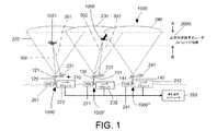
図1〜図3を参照すると、低空飛行体を追跡するための、特に低空飛行無人航空機(UAV)及び他の物体を追跡するためのシステムの例示的な実施形態が示されている。システムは、本明細書に開示された方法に従って実施されることができ、装置は、システム及び方法を実施するために提供され、かつ及び構成され得る。好ましい実施形態によれば、システムは、既存のセルタワーと共に実施され得る。代替として、システムは、既存のセルタワー及び幾つかの追加コンポーネントで実施されてもよく、あるいは幾つかの他の代替実施形態によれば、UAV/RPV通信専用の別個に設けられたタワー、送信機、及び他のコンポーネントを使用して実施されてもよい。他の実施形態によれば、システムは、地上ベースの通信送信機の別個の分散型ネットワークを使用して実施されてもよい。 With reference to FIGS. 1 to 3, an exemplary embodiment of a system for tracking low flying vehicles, in particular for tracking low flying unmanned aerial vehicles (UAVs) and other objects is shown. A system can be implemented in accordance with the methods disclosed herein, and an apparatus can be provided and configured to implement the systems and methods. According to a preferred embodiment, the system can be implemented with existing cell towers. Alternatively, the system may be implemented with an existing cell tower and some additional components, or according to some other alternative embodiments, a separately provided tower dedicated to UAV / RPV communication, a transmitter And other components may be implemented. According to another embodiment, the system may be implemented using a separate distributed network of ground based communication transmitters.
本発明によるシステムの実施形態は、例示的な実施形態に従って示されており、コンポーネントは、例えば、UAV及び他の物体などの低空飛行体を追跡するように配置されている。図1の例示的な描写では、鳥1060又はUAV1051が、通信データグラムトランシーバの「セルタイプ」グリッドによってカバーされる領域を飛行するときに、これがシステムによって追跡され得る。ネットワークは、ノード1000’、1000”、1000”’からなることが示されている(また図示されていない幾つかの追加ノードを含み得るが)。ノード1000’、1000”、1000”’は、カバレッジ領域内の物体からの反射を受信するための関連する通信機器及びそれ自体のローカルアンテナアレイ又はフェーズドアレイアンテナを含み、領域上に配備された複数のノードにわたる物体の領域的な追跡を行うために、他のノードにネットワーク接続された中央集約型追跡コンピュータ280にデータを返信するレーダ処理能力を有する。 An embodiment of a system according to the invention is shown according to an exemplary embodiment, wherein the components are arranged to track low flying vehicles such as, for example, UAVs and other objects. In the exemplary depiction of FIG. 1, the
図1に示されるように、セルタワー120、130、140の配置が、UAV及び他の低空飛行物体の追跡を行うための分散型ネットワークのセグメントを表すために示されている。この例示的な実施形態では、ネットワーク通信システム1000が示されており、3つのノード1000’、1000”、1000”’が描写されている(探知領域全体に分散ネットワークを構成するために提供される他の同様のノードがある)。各ノード1000’、1000”、1000”’は、それぞれのタワー120、130、140、それぞれ関連する無線ネットワーク通信機器(WNE)261、271、281及びレーダ探知コンポーネントによって表されることが示されている。無線ネットワーキング通信機器(WNE)261、271、281は、好ましくは、1つ又は複数のアンテナ(例えば、121、131、141)と結合されたトランシーバを含み得る送受信機器(トランシーバ装置)を含む。タワー120、130、140は、好ましくは、1つ又は複数の関連するアンテナ(例えば、121、131、141)を備えており、その上に支持されたアンテナアレイを含み得る。システムは、本明細書で参照される本出願人の米国特許出願に開示されている通信システムを使用して実施され得るため、それらの空方向UAV通信システムのトランシーバ及び送信アンテナは、レーダ探知システムと、好ましくはレーダ探知コンポーネントと共に利用され得る。 As shown in FIG. 1, the arrangement of cell towers 120, 130, 140 is shown to represent segments of a distributed network for tracking UAVs and other low flying objects. In this exemplary embodiment, a
タワー120、130、140は、好ましくは、例えばトランシーバ、アンテナ、電源、及びセルラー通信を生成及び受信するための他の機器などの、それぞれの通信機器を備え、又はそれに関連付けられている。図1に示される例示的な描写では、各タワー120、130、140は、例えばそれぞれのアンテナ(又はアンテナアレイ)121、131、141に関連する無線ネットワークデータグラムRF送受信機器(WNE)261、271、281などのRF生成機器を設けて構成される。無線ネットワークデータグラムRF送受信装置(WNE)は、好ましくは、(図1のネットワーク1000、及びその一部1000’である図2などの)通信ネットワークを介して信号を生成及び受信するためのコンポーネントと、例えば信号及びデータグラムを受信及び/又は送信することを可能にするためにそれ自体の送受信機器を有して構成されたUAV1051などの、ネットワークを介して通信する機器とを含む。無線ネットワークデータグラムRF送受信装置(WNE)(例えば、261、271、281を参照)は、好ましくは、信号処理及び生成コンポーネントを含み、UAV1051との通信のために信号を空方向に上方に放射する複数の関連するアンテナ121、131、141に信号を提供する。信号は好ましくは空方向の円錐パターンで放射され、空方向の放射円錐220、230、及び240が信号カバレッジの領域を表すように描かれている。放射信号は、地面の上空にある連続的なカバレッジ領域2000の上空領域を提供するように生成される。これは、所望のカバレッジ領域を生成するようにアンテナを配置し、又はそれらを調整することによって達成され得る。図1の矢印AとBとの間の領域は、地面に対して上昇したレベルで設けられた連続的なレーダカバレッジ領域2000を表し、好ましい実施形態では、放射円錐220、230、240によって、特に、これらの円錐の上昇領域によって形成されたように描かれている。上昇領域2000は、好ましくは、低飛行物体の存在が探知され得るレーダカバレッジ領域を表す範囲(この図では矢印AとBの間)に設けられる。 The
図1及び2に示されるように、RF信号は、方向的には上向きに空を指向する。図示された例では、放射信号220、230、240は、この描写ではそれぞれのセルタワー120、130、140を含むセルタワーシステムからの信号アンテナであるそれぞれの関連するアンテナ(又はアンテナグループ)121、131、141から伝搬される。信号は上方に放射され、好ましくは、領域2000内のデバイスとの通信及び/又はデバイスからの反射に適する信号強度を提供するように制御され得る。 As shown in FIGS. 1 and 2, the RF signal points sky in the upward direction. In the illustrated example, the radiation signals 220, 230, 240 are respective associated antennas (or antenna groups) 121, 131, which in this depiction are signal antennas from the cell tower system including the respective cell towers 120, 130, 140. It is propagated from 141. The signal is emitted upwards and can preferably be controlled to provide a signal strength suitable for communication with and / or reflection from the device in
レーダ探知機構は、セルラーネットワーク通信システムと共に示されている。図示されたセルラー通信システムは、UAVとの通信のために構成され、好ましくは空方向に投影されたセルラーシステムを含む。空向きのセルラー通信システムは、UAVの指揮・制御、及び/又はナビゲーション機能の通信のために別個の周波数又は帯域(及び他のタイプのUAV通信、例えば、カメラ操作及びフィードなどのための周波数、又は周波数範囲)を提供し得る。図1の例示では、レーダ探知機構がセルラー通信配置と共に設けられて示されている。レーダ探知機構は、好ましくは、信号を受信するためのアンテナ又はアンテナアレイ、及び信号を処理するためのレーダプロセッサを設けて構成される。図1には、UAV及び他の物体などの空中の物体を探知するためのレーダ探知機構210を含むシステムの例示的な実施形態が示されている。レーダ探知機構210は、信号探知用受信アンテナ221及び関連するレーダプロセッサ222が設けられているセルタワー120などの第1の通信タワーに関連して示されている。信号探知受信アンテナ221は、好ましくは、WNE261によって生成され、アンテナ(1つ又は複数)121から放射される、物体から反射された信号、又はエコーを含むRF信号を受信するRXアンテナ又はアンテナアレイ(例えば、受信アンテナ221a又はアンテナアレイ221b)を含み得る。好ましくは、アンテナ221は、レーダ探知機能専用である。RXアンテナ又はアンテナアレイ221a、221b(レーダ機能専用)は、WNEアンテナ又は平面フェーズドアレイアンテナ用に使用されるタワー120などの同じ構造上に、又はその近傍に配置され得る。アンテナ221は、無線ネットワーク(WNE)のために使用されるタワーの上に、又はその近傍に配置され得る。例えば、システムが無線通信ネットワークと共に使用される図1において、タワー120は、ネットワークを介して(例えば、ネットワークと通信デバイス間で)無線通信を実行するための複数のアンテナ121又はアンテナアレイ、及びこれもタワー120に支持されたレーダアンテナ221を備えて示されている。それぞれのタワー130、140上の追加のアンテナ231、241が、好ましくはそれぞれのWNE271、281に関連して機能するように構成された、それぞれ関連するレーダプロセッサ232、242と共に示されている。レーダ機構は、UAV及び低空飛行物体を探知するように構成される。好ましい実施形態によれば、レーダ追跡システムは、レーダ機能を提供するための信号を通信するためにネットワーク1000を利用する。レーダアンテナ221、231、241は、セルタワー120、130、140上に支持され、(例えば、幾つかの実施形態によれば、UAV及び指揮・制御コンピュータとの通信のための通信ネットワークである)ネットワーク1000の送信及び受信コンポーネント間の通信交換のために信号を中継する(WNE261、271、281などの)の関連するセルラー通信コンポーネントと共に動作するように構成され得る。 The radar detection mechanism is shown with a cellular network communication system. The illustrated cellular communication system comprises a cellular system configured for communication with the UAV, preferably projected in the air direction. Airborne cellular communication systems may use separate frequencies or bands (and other types of UAV communications, eg, for camera operations and feeds, etc.) for UAV command and control, and / or communication of navigation functions. Or frequency range) may be provided. In the illustration of FIG. 1, a radar detection mechanism is shown provided with a cellular communication arrangement. The radar detection mechanism preferably comprises an antenna or antenna array for receiving the signal and a radar processor for processing the signal. An exemplary embodiment of a system including a
レーダ探知機構は、WNE及びレーダアンテナ221、231、241に加えて、好ましくは、関連するレーダプロセッサ222、232、242を含む。レーダプロセッサは、例えばWNE無線トランシーバなどの関連するWNEから送信された信号を監視するための命令を含んで構成され得る。好ましい構成によれば、レーダプロセッサ(222、232、242)は、セルタワー(120、130、140)に関連付けられ、例えば、タワーアンテナ配置121、131、141(図1参照)によって生成されたそれぞれの信号円錐220、230、240で表される、例えば伝搬エリアなどのタワー範囲内の探知を行う。各レーダプロセッサ222、232、242は、(例えば、図1のタワー120上のアンテナ121の配置などの)トランシーバ関連のアンテナを介して伝搬される信号を生成又は監視するように構成される。信号は、破線300によって表され、図示されているように、例えば例示的な描写におけるUAV1051などの物体に遭遇すると反射される。エコーとも示称され、破線301によって表されている反射波は、この実施形態では、(UAV1051から反射されることが示されている)反射信号を受信するために設けられた受信アンテナであるアンテナ221によってピックアップされる。UAV1051は、レーダノードへの復帰を強調することによって反射信号を促進するために、コーナーリフレクタなどの反射器を設けて構成され得る。レーダプロセッサ222は、反射された信号又はエコー301を受信する。レーダプロセッサ222は、好ましくは、レーダ機構によって監視されている(低空飛行物体などの)空域内の物体の探知を行うためにデータを受信し、記憶し、処理し得るコンピュータコンポーネントを設けて構成される。 The radar detection mechanism preferably includes an associated
図1では、セルラー通信ネットワーク1000(又はその一部)が表され、空方向システムを介して、UAVなどの低空飛行体のための通信を提供するように構成される。レーダシステムは、好ましくはネットワーク1000のコンポーネントを含む地上ベースの通信送信機のネットワーク全体に分散される。レーダシステムの信号源コンポーネントは、システムが探知しようとするUAV及び他の低空飛行物体などの標的に効果的に比較的密接するように構成され得る。空方向レーダ探知システムは、カバレッジ領域2000を含んで構成された例示的な図に示されている。この領域内の物体が追跡され得る。例えば、図1には、鳥1060として表される物体が、連続的なカバレッジの領域2000に示され、無線ネットワークデータグラムRF送受信機器(WNE)271によって生成された放射の信号円錐230内に配置され、タワー130及び配置されたアンテナ131と関連付けられる。関連するレーダプロセッサ232が示され、好ましくはWNE271によって送信された信号のコピーを含むデータを受信する。システムは、好ましくは、近位に配置された受信アンテナ231によってピックアップされ、レーダプロセッサ242などの処理及び/又は監視コンポーネントで監視される短い通信バーストを含み得る、例えば、円錐230によって表される領域などの送信領域内の信号を生成するように構成される。例示的な実施形態では、図示された好ましい実施形態によれば、システムは、通信ネットワーク、好ましくは分散セルラー通信ネットワークを介して動作するように構成される。図示された実施形態では、信号302は、送信機(例えばWNE251の送信機)から送信され、領域2000内の鳥1060に遭遇する。信号は鳥1060に到達し、信号又はエコー303が取り1060から反射される。反射された信号303は、受信アンテナ231によって受信され、レーダプロセッサ232によって利用できるようにされる。この時点でレーダプロセッサは、WNE251から送信された信号のコピー及びエコー信号303を有する。 In FIG. 1, a cellular communications network 1000 (or a portion thereof) is depicted and configured to provide communications for low flying vehicles such as UAVs via an air direction system. The radar system is distributed throughout the network of ground based communication transmitters, which preferably includes the components of
図示された好ましい実施形態によれば、システムは通信ネットワーク、好ましくは分散型セルラー通信ネットワークを介して動作するように構成される。システムは、好ましくは、集約型追跡コンピュータ280などの集約型コンピューティングコンポーネントを含む。集約型追跡コンピュータ280は、好ましくは、探知信号の伝播及び受信に関連する信号、又はそれらの信号の副産物の形態であってもよいデータを受信するように電子的に接続される。集約型追跡コンピュータ280は、好ましくは、ネットワーク通信システムの複数のノードの中央コンピューティングリソースとして機能するように構成される。例えば、集約型追跡コンピュータ280は、UAV及び他の低空飛行物体などの物体の地域的な追跡を行うために領域の複数のノードに関連付けられ得る。集約型追跡コンピュータ280は、ネットワーク1000に渡って探知情報を受信し、管理し、図示のように、ネットワークノード1000’、1000”、1000”’からの信号データが提供される。 According to the illustrated and preferred embodiment, the system is configured to operate via a communication network, preferably a distributed cellular communication network. The system preferably includes integrated computing components, such as integrated tracking
図2を参照すると、空方向のゾーン又は領域内のUAV及び他の低空飛行物体を探知及び監視するためのレーダ探知システム1000のノード1000’を示す例示的な実施形態が示されている。図示したシステムでは、アンテナシステムから信号を上方に放射することによってUAVと通信するための通信システムが示されている。ノード1000’は、アンテナ121及び無線データグラムRF送受信機器(WNE)261を設けて構成されるタワー120を含むものとして示されている。WNE261は、好ましくは、通信ネットワーク1000の一部であり、ネットワーク1000を経由した通信及び他のデータなどの情報を交換するために電子的にリンクされている。ノード1000’は、追跡システムの一部を含むものとして図示されている。図1には、第1のノード1000’、第2のノード1000”、及び第3のノード1000”’を含む3つのノードが示されている。ノード1000’、1000”、1000”’は、通信ネットワーク1000を備え、好ましくは、指定された、又は所望のカバレッジゾーン又は領域にわたってカバレッジを提供するように構成される。ノードは、好ましくは、監視が必要なエリアに空方向の領域2000のカバレッジがあるように配置される。図1では、3つの領域がそれぞれの円錐120、130、140によって形成されて示されている。システムは、好ましくは、ネットワークを拡張するため、(図1の3つのノードによってカバーされる領域以外の)追加のタワー及びWNEを含むように構成される。好ましくは、(WNE261の一部として又はこれと関連して設けられ得る)トランシーバと共に配置されるコンピューティングコンポーネントは、アンテナ121から放射され、空方向に伝播されるRF通信信号を生成するように構成される。これは、セルラー通信ネットワークの一部として、より具体的には、本明細書で参照した私出願人の先願に開示された空方向に向けられる通信システムで実行され得る。レーダ探知システムは、既存のセルラーシステム(ならびに空方向の通信ゾーンを介して通信するように構成されたセルラーシステム)と組み合わせてコンポーネントを提供することによって実施され得る。 Referring to FIG. 2, an exemplary embodiment is shown illustrating a node 1000 'of a
システムは、アンテナから発信される信号を監視するように構成される。送信アンテナ121、131、141には、好ましくは、それぞれ関連するWNE261、271、281からのRF信号が供給される。信号は、上方の空方向に伝搬される。信号円錐は、好ましくは、構造の周囲を回避するか、又はその周囲で動作し得る空方向に向けられたカバレッジの多数の狭い領域を提供するように生成される。信号は、好ましくは、拡張されたカバレッジ領域を提供するために集約され得る幾つかのより小さな領域の探知カバレッジを提供するように伝搬される。好ましくは、信号は、UAVが運航する(及び探知されることが望ましい他の物体が存在し得る)領域に到達するのに適する強度を有して生成される。送信信号が生成される。送信信号は、アンテナ121に送信されて信号を上方に放射し、信号のコピーもまたレーダプロセッサ222に送信される。したがって、レーダプロセッサ222は信号を受信し、信号が生成された時刻が提供される。実際には、幾つかの信号が生成され、それらの生成時刻、周波数、変調データ(及び他の特性)を含を含め、信号のコピーがレーダプロセッサ222によって監視される。好ましくは、受信アンテナ221からの信号を受信するためにレーダプロセッサ222が接続される。UAV1050(又は探知領域内の他の物体)などの物体から反射され得る信号を含め、受信アンテナ221から生成された信号を受信するように受信アンテナ121が備えられる。反射された信号301は、処理され、(例えば、WNE261から)レーダプロセッサに提供される生成された信号コピーと比較される。受信アンテナで受信された反射信号は、他の信号と共に受信され得る。探知ゾーン内の飛行物体の存在に起因すると予測される反射信号又はエコーを識別するために、(アンテナ221などの)受信アンテナから受信された信号の処理が実行される。例えば、信号のコピーが連続的なフレームに渡ってレーダプロセッサに提供され、特定の継続時間内に、又はその信号周波数について反射信号が受信されない場合、(又は、物体の存在を示す信号が返信されない場合)でも、レーダプロセッサはその監視状態を継続する。しかし、空方向の物体からの反射信号が受信される場合、レーダプロセッサは物体の探知を識別し、物体の位置及び動きを示すために受信された他の信号と共に信号をさらに処理し得る。レーダ探知システムは、好ましくは、反射信号の探知を処理し、探知された物体を識別するときにも、信号の監視を継続するように構成される。レーダプロセッサは、そのノードでカバーされる空方向の領域(又はレーダプロセッサがカバーするように指定された他の領域)内の複数の物体を識別し得る。幾つかの実施形態によれば、システムは、UAVに対して行われる通信と同じ周波数を使用するように構成され得る。例えば、通信がアンテナ121から(例えば、イメージング、配信などのペイロードアプリケーションのための1つのサブバンド上で、又は指揮、制御、及びナビゲーション機能などの重要なUAV運航の通信のために確保された別の指定されたサブバンド上で)、領域2000内で運航するUAV1051のために、又は、そのUAV1051に向けて空方向に送信される場合、レーダプロセッサは、同様に信号のコピーを受信し得る。信号は、無線ネットワーク装置(WNE)によって生成され、好ましくは、レーダプロセッサ222に供給される特定の周波数及び信号のコピーでアンテナ121から放射される(好ましくは、特定の周波数でアンテナ121から放射され、信号のコピーがレーダプロセッサ222に供給される)。レーダプロセッサ222は、好ましくはパッシブレーダプロセッサであり、よく知られている幾つかの方法のうちのいずれか1つに従って信号情報を処理するように構成され得る。レーダプロセッサ222などのレーダプロセッサの実施形態は、プロセッサ、マイクロプロセッサ、コントローラ、マイクロコントローラ、マイクロチップ、又は他の処理回路などのコンピューティングコンポーネントと、受信アンテナによって受信された信号の処理をプロセッサに指示するために使用される命令を記憶するためのフラッシュメモリ又は他のメモリチップ、ハードドライブなどを含む。レーダプロセッサ222は、好ましくは生の、又は処理された信号情報を記憶し、及び/又はさらなる処理又は記憶のためにその情報を別のコンピューティングコンポーネントに送信するように構成され得る。例えば、図1の描写は、空方向ネットワークのノードとそのノードのWNEとに関連する3つのレーダプロセッサ222、232、242を示す。レーダプロセッサ222、232、242は、集約型追跡コンピュータ280として識別されるコンピュータとの通信のために接続されるように示されている。追跡コンピュータ280は、レーダプロセッサ222、232、242から生データを受信し、又は幾つかの実施形態によれば、処理された信号データ又は部分的に処理された信号データを受信し得る。集約型追跡コンピュータ280は、好ましくは、監視されているネットワークの空方向領域内のUAV及び他の低空飛行物体などの空方向の物体を識別し得る。集約型コンピュータ280自体が、又は他のコンピューティングコンポーネントと一緒になって、物体が互いに近くにあるなどの潜在的な危険がある場合(例えば、UAV1051が鳥1060に近接している場合、図1参照)、警報を発するように空域を管理し得る。レーダ追跡システムは、UAV交通制御システムと共に操作され、自律的に運航するUAVの動作を制御又は管理する自律的な航空交通制御システムと統合され得る。レーダシステムは、(例えば、近くの気球や鳥などの)潜在的な脅威又は危険の探知が判定された場合の(例えば、飛行経路、方向、速度など)の操作又は制御を含み得るUAVの管理又は警報を提供するためにレーダ信号を処理するように構成され得る。例えば、UAV航空交通制御は、その飛行経路が(UAV飛行領域内で動いており、又は固定されている場合がある)別の接近する物体と一致すると判定されたUAVをホバリングさせ得る。 The system is configured to monitor the signal emanating from the antenna. The transmit
受信アンテナ221、231、241から受信した信号情報のレーダ処理は、既知のレーダ信号処理方法に従って実行され得る。例示的な実施形態によれば、(レーダプロセッサ222、232、242のいずれかなどの)パッシブレーダプロセッサは、アンテナ(図1及び図2に示されるような221a又は221b、231、241)から信号を受信し、情報を操作して、監視されている空方向領域内の物体の位置、サイズ、及び動きに関する情報を生成するように構成される。この情報は物体の探知を提供し、また物体がその領域内を移動する際に物体の追跡を提供する。方向及び速度を含む空方向の物体の動きは、レーダ探知システムによって決定され得る。探知システムはまた、物体自体に関する情報を提供し、物体の種類、又はあり得る物体の種類を区別及び/又は識別するために使用され得る。例えば、1つの信号パターンはUAVに対応するものとして識別され得る一方、他の信号パターンは物体を鳥として識別し得る。システムは、好ましくは、信号情報を処理するように構成され、例えば、UAV、鳥、気球などの、探知される筈の物体に対応するパターンが提供され得る。1つ又は複数の識別パターンは、特定の物体の基準(リファレンス)として記憶され得る。信号パターンのデータベースは、領域内の予測される、又は既知の物体の以前の探知に基づいて生成され得る。レーダシステムが受信アンテナからの反射信号を受信すると、整合するかどうかがデータベースで照合され得る。これは好ましくは、レーダプロセッサ(例えば、222、232、242)又は集約型追跡コンピュータ280などの処理コンポーネントによって実行される。 Radar processing of signal information received from the receiving
図3は、受信アンテナによって受信された信号のレーダ処理に関連して実施される方法の一例を示す。図3に示されるように、ブロック400で、複数のアンテナを表すアンテナアレイが示されている。複数のアンテナは、例えば、受信アンテナ221、231、241(及び図2の受信アンテナ又はアレイ221a、221b)など、図1のシステムに関連して示されたアンテナであってもよい。幾つかの実施形態によれば、アンテナアレイは、幾つかのアンテナ素子及び素子レベルのデジタル化で構築された単純なアンテナアレイであってもよい。ブロック401で、受信された信号の到達方向を判定するために、デジタルビームフォーミングが実行される。反射された信号又はエコーの到達方向は、標準のレーダビームフォーミング技術を用いて計算され得る。複数のアンテナ素子が示されているが、幾つかの実施形態によれば、一対のアンテナ素子が利用され、エコーの到達方向を判定するために到達の位相差が使用され得る。幾つかの実施形態によれば、アンテナのフェーズドアレイが使用され得る。さらに、ブロック402で、受信された信号は、好ましくは信号調整を受ける。さらに、ブロック403の送信信号のコピーもまたブロック404で調整され得る。ブロック406の相互相関処理の前に信号の一部を操作するために信号調整が実施され得る。信号調整は、ブロック402、404で、信号対干渉比(SIR)を改善するために実行され得る。ブロック401のビームフォーマが別個に図示されているが、これは信号調整の一部を構成し得る。レーダプロセッサは、好ましくは適応フィルタを設けて構成される。適応フィルタは、好ましくは、信号を操作して直接信号を除去するために使用される。適応フィルタリングは、ブロック405の適応除去とも称され得る。幾つかの実施形態によれば、例えば、適応フィルタリングは、チャネル間の受信データの相関特性を調べることによって実行される。このようにして、アンテナパターンサイドローブに入るジャミング及びクラッタの存在が識別され得る。チャネルは、アンテナに高利得メインローブ及び概略低いサイドローブを提供するために、重みのセットに従って結合され得る。適応フィルタリングはまた、チャネルを結合し、ジャマーの到達角でアンテナパターンにnull値を生成する重み付けを提供し得る。図示されたレーダ処理例では、処理は相互相関処理のブロック406を含み得る。相互相関処理のブロック406は、相互の遅延の関数として2つの系列の類似性を測定するように設計される。レーダ処理の例では、相互相関のブロック406は、各標的エコーのバイスタティックレンジ及びバイスタティックドップラシフトの推定値を提供する。相互相関は整合フィルタとして機能する。これは、各々が異なる標的ドップラシフトに整合された整合フィルタのバンク(又は集合)を設けることによって実施され得る。ブロック407で、セル平均一定誤警報率(CAFR/Cell-averaging constant false alarm rate)アルゴリズム処理が実施される。CAFR探知、ブロック407は、標的を探知するように設計されている。相互相関面上方の標的を探知するために適応閾値が適用される。レーダプロセッサは、相互相関面上方の全てのリターンが探知の対象であると見なされるように、CFAR検出を実施するように構成され得る。(UAV及び他の低空飛行体などの)標的は、好ましくは時間全体を通して追跡され、したがって、それらの移動、方向及び速度に関する情報が確認され得る。例えば、監視されている空方向領域内を移動するUAV、鳥、気球などの物体の場合、これらの移動物体から反射されたエコーの周波数シフト(例えば、ドップラ効果)が観測され、探知され得る。この情報は、UAV、鳥などなどの低空飛行体の位置及び、物体の移動方向と速度とを提示し得る。好ましくは、システム内の各送信機(トランスミッター)について、又は監視されているネットワーク領域の一部の各送信機の集合において、ライン追跡(ライントラック)は、(それぞれの送信機用のライントラッカを表す)ライントラッカ、ブロック408a、408b、408cを介して実施される。例えば、図1を参照すると、送信機261、271、281は、好ましくは、それぞれのライントラッカ408a、408b、408cに関連する信号を供給する。レーダプロセッサは、個々の標的からの標的リターンのライン追跡を実施するように構成され得る。これは、好ましくは、ブロック406で、相互相関処理によって生成された範囲−ドップラ空間内で経時的に実行される。追跡関連付け及び追跡推定、ブロック409は、UAV又は他の低空飛行体の位置を判定するために実行される。追跡関連付けは、単一の送信機及び単一の受信機を使用して実行されることができ、又は幾つかの実施形態によれば、1つ又は複数の受信機を使用して実行することができ、その場合、UAV又は他の物体などの物体が潜在的に各受信機によって探知され、それ自体が1つ又は複数の送信機と関連付けられ得る。例示的な実施形態は、複数のノードを用いて示されており、図示された各受信機ノードに関連する送信機が参照されるが、システムは、複数の受信機が使用されて、単一のタワーアンテナから送信機によって伝搬され、かつ反射される信号を受信するように構成され、受信された信号は、一方の送信機からのどの標的リターンが他方の受信機上のものと対応するかを判定するように処理される。信号リターンは、1つ又は複数の受信機によって受信された反射信号から提供される信号情報を使用して物体の位置を判定するために関連付けられる。標的トラック、ブロック310は、処理された信号データから生成され、UAV(又は他の物体)の方向、速度及び位置の指示を提供する。したがって、これはレーダ処理の一例であり、他のレーダ処理方法を用いて、ネットワークシステムから生成された信号データを処理し、UAVの位置及び追跡を行い得る。 FIG. 3 illustrates an example of a method implemented in connection with radar processing of a signal received by a receiving antenna. As shown in FIG. 3, at
図2に示されるように、信号線トレース306が示されている。送信機121からの信号又は光線305は、物体、すなわちカバレッジ領域内のUAV1051に遭遇する。図2では、UAV1051は、図1に示される位置から移動している。参考のため、UAVは、信号円錐220によって表される空方向領域内にある。一例によれば、レイトレーシングは、UAV1051などの物体の移動を追跡するように実施され得る。UAV1051に到達すると、信号光線305の一部が吸収されるか、又は散乱される。信号光線306は、受信アンテナ221a又は221bによって受信可能なUAV1051から反射された信号(反射された光線305の部分)を表す。レーダプロセッサ222は、好ましくは、信号コピー310の受信を介して信号光線305の知識を有する。一つの代表的な信号光線305及び一つの反射信号光線306が示されているが、幾つかの信号光線が領域220内に送出され、反射された各信号光線のトレースが識別され、処理が繰り返されてUAV1051の経路が導出される。 As shown in FIG. 2, signal line trace 306 is shown. A signal or ray 305 from
好ましい実施形態によれば、システムは、空方向通信システムのための無線ネットワーク機器と共に実施される。例えば、送信機は、物体に放射され、物体から反射されるとレーダプロセッサに関連する受信アンテナによって探知される連続波信号を含む送信信号を送出し得る。好ましい実施形態によれば、送信信号は、(例えば、空方向に向けられた送信機/アンテナからのUAVへの送信などの)セルラー通信のために提供されるRF信号である。好ましい実施形態によれば、レーダプロセッサは、(直接信号と示称され得る)送信信号のコピーを受信し、物体から反射された信号をも(関連する受信アンテナを介して)受信する。反射された信号は直接信号ではない(散乱されたと考えられる)。レーダプロセッサは、(直接及び反射の両方の)信号を受信し、信号を区別するように構成される。信号属性(例えば、送信時間、受信時間、周波数及び変調されたデータなど)は、レーダプロセッサによって取得され、探知結果を提供するために分析される。送信が行われている探知領域内に物体(UAV又は鳥など)が残っていると、反射信号はレーダプロセッサによって受信され続け、物体の動き及び位置が監視及び追跡され得る。探知エリアは、エリア全体を通して物体を追跡するために複数の探知領域を含むことができる。レーダプロセッサは、レーダプロセッサにネットワーク接続された集約型コンピュータであってもよいレーダシステムコンポーネントに情報を提供するためにネットワークの一部として構成され得る。あるいは、幾つかのレーダプロセッサがあるノード上に、及び他のノードのレーダプロセッサが集約されたノード上に設けられてもよい。あるいは、幾つかのレーダプロセッサがあるノード上に設けられ、そのノードが他のノードのレーダプロセッサと集約されてもよい。 According to a preferred embodiment, the system is implemented with a wireless network device for an air-directed communication system. For example, the transmitter may emit a transmit signal that includes a continuous wave signal emitted to the object and detected by the receiving antenna associated with the radar processor when reflected from the object. According to a preferred embodiment, the transmit signal is an RF signal provided for cellular communication (e.g., transmission to the UAV from an air directed transmitter / antenna). According to a preferred embodiment, the radar processor receives a copy of the transmitted signal (which may be referred to as a direct signal) and also receives the signal reflected from the object (via the associated receiving antenna). The reflected signal is not a direct signal (considered scattered). The radar processor is configured to receive the signals (both direct and reflected) and to distinguish the signals. Signal attributes (eg, transmit time, receive time, frequency, modulated data, etc.) are acquired by the radar processor and analyzed to provide detection results. If an object (such as a UAV or a bird) remains in the detection area where transmission is taking place, the reflected signal will continue to be received by the radar processor and the movement and position of the object may be monitored and tracked. The detection area can include multiple detection areas to track objects throughout the area. The radar processor may be configured as part of a network to provide information to radar system components, which may be an integrated computer networked to the radar processor. Alternatively, some radar processors may be provided on one node, and radar processors of other nodes may be provided on an aggregated node. Alternatively, several radar processors may be provided on a node, and that node may be integrated with the radar processors of other nodes.
幾つかの実施形態によれば、信号到達時間は、レーダ探知応答を提供するために判定され、使用され得る。実施形態は、信号を分離するために信号の処理を実施するようにレーダプロセッサを構成し得る。UAV又は鳥などの物体が動いている場合、物体の動きは、例えば、UAV又は鳥からの反射又は散乱された信号にドップラシフトを誘発し得る。シフトは、2つの信号の周波数の分離を容易にする。レーダ処理は、信号を探知し、評価する処理方法に従って実行され得る。信号の区別は、空方向領域内の物体の存在を判定する方法をもたらす。 According to some embodiments, signal arrival time may be determined and used to provide a radar detection response. Embodiments may configure the radar processor to perform signal processing to separate the signals. When an object such as a UAV or a bird is moving, the movement of the object may induce a Doppler shift in the reflected or scattered signal from the UAV or a bird, for example. The shift facilitates separation of the frequencies of the two signals. Radar processing may be performed according to a processing method that detects and evaluates signals. Signal discrimination provides a way to determine the presence of an object in the sky area.
本システムの実施形態によれば、送信機は、送信機の無線周波数搬送波に付加される送信コードを利用し得る。コードは、一連の離散的な送信機位相レベルとして提供され得る。コードは、Lビット後に回帰され得るため、擬似乱数コードである乱数コードであってもよい。送信は、シフトレジスタ段Nの数に基づいて周期的に反復されるコードワード又は長さLビットのシーケンスを含み得る。例えば、Lビットの場合、N個のシフトレジスタ段について式はL=2^N−1である。一実施形態によれば、クロックパルス発生器が備えられ、コーダシフトレジスタに供給するように構成される。例えば、クロックパルスが印加されるたびに、シフトレジスタは、(例えば、線形表現を考慮すると右に一段)シフトされ得る。好ましい実施形態によれば、擬似乱数コードを含むコードは、WNEのトランシーバからの搬送波のRF送信に関連して提供されるコードである。 According to embodiments of the present system, the transmitter may utilize a transmission code attached to a radio frequency carrier of the transmitter. The code may be provided as a series of discrete transmitter phase levels. The code may be a random number code, which is a pseudorandom number code, since it can be regressed after L bits. The transmission may include a codeword or a sequence of L bits of length periodically repeated based on the number of shift register stages N. For example, for L bits, the equation is L = 2 ^ N-1 for N shift register stages. According to one embodiment, a clock pulse generator is provided and configured to supply a coder shift register. For example, each time a clock pulse is applied, the shift register may be shifted (e.g., one step to the right considering a linear representation). According to a preferred embodiment, the code comprising the pseudorandom code is a code provided in connection with the RF transmission of the carrier from the WNE's transceiver.
レーダプロセッサは図示されているが、レーダプロセッサは、別個のコンポーネントとして提供されてもよく、又は分散型ネットワークハードウェアのうちの1つ又は複数と関連して提供されてもよい。一実施形態が図3に示されているが、パッシブレーダプロセッサは、図3に示されているもの以外の幾つかの方法のうちのいずれか1つに従って受信された信号を操作し得る。 Although a radar processor is illustrated, the radar processor may be provided as a separate component or may be provided in connection with one or more of the distributed network hardware. Although one embodiment is shown in FIG. 3, a passive radar processor may manipulate the received signal according to any one of several methods other than that shown in FIG.
このシステムの実施形態は、カバレッジ領域内のUAVと通信するために放射されている通信送信を利用する。幾つかの代替実施形態によれば、例えば、カバレッジ領域内にUAVが存在しない場合など、通信送信が放射されていない場合に情報を生成するための代替実施形態が提供され得る。この代替実施形態では、システムは、UAVへの定期的な通信送信がない場合に、空方向指向性の通信システムに空方向への定期的な送信を送出させ得る。別の実施形態によれば、送信機は、周期的又は定期的な送信を空方向に送出し得る。これらは空方向の通信システムによって生成され得る。幾つかの実施形態によれば、所定期間の間、送信機からの通信送信がない場合、定期的な送信が送信され得る。幾つかの代替実施形態によれば、定期的な送信は、送信機からの通信送信が所定期間の間に存在しない場合に生成され得る。別のシステムはまた、例えば、定期的な送信により、レーダプロセッサが空方向の領域又はゾーン内の物体を肯定的に探知した場合に、レーダ探知コンポーネントから信号を受信するように構成され得る。送信機は、レーダプロセッサ探知からの結果としての通知信号を受信すると、定期的な送信を引き続き送信して、探知された物体を監視し得る。物体が探知ゾーン内に留まり、及び/又は探知ゾーンを通過する際にレーダプロセッサが探知物体からエコーを受信し得るように、定期的な送信が送信されてもよく、あるいは、連続した信号波が放射されてもよい。したがって、物体がゾーン外に移動し、非活動期間になると、システムは、別の物体が探知されるような時間まで、再び周期的送信に頼り得る。これらの代替実施形態によれば、定期的送信のコピーが関連するレーダプロセッサに送出され得る。レーダプロセッサは、受信アンテナから受信した信号、及び定期的送信の信号コピーを処理して、物体、例えば鳥(又は他の非通信物体)がその領域内に存在するかどうかを判定する。 Embodiments of the system utilize communication transmissions being emitted to communicate with UAVs in the coverage area. According to some alternative embodiments, an alternative embodiment may be provided for generating information when communication transmissions are not radiated, such as, for example, when there is no UAV in the coverage area. In this alternative embodiment, the system may cause the sky-oriented communication system to send out periodic periodic transmissions in the absence of periodic communication transmissions to the UAV. According to another embodiment, the transmitter may send periodic or periodic transmissions in the air direction. These may be generated by the air communication system. According to some embodiments, periodic transmissions may be transmitted if there is no communication transmission from the transmitter for a predetermined period of time. According to some alternative embodiments, periodic transmissions may be generated if communication transmissions from the transmitter do not exist for a predetermined period of time. Another system may also be configured to receive a signal from the radar detection component if the radar processor positively detects an object in the sky area or zone, for example by periodic transmission. The transmitter may continue to transmit periodic transmissions to monitor the detected object upon receiving notification signals from the radar processor detection as a result. Periodic transmissions may be sent so that the radar processor can receive echoes from the detected object as the object stays in the detected zone and / or passes the detected zone, or a continuous signal wave is It may be emitted. Thus, when an object moves out of the zone and becomes inactive, the system may again rely on periodical transmission until such time as another object is detected. According to these alternative embodiments, a copy of the periodic transmission may be sent to the associated radar processor. The radar processor processes the signal received from the receive antenna and the signal copy of the periodic transmission to determine if an object, such as a bird (or other non-communicating object), is present in the area.
これら及び他の利点は、本発明によって実現され得る。本発明を特定の実施形態を参照して説明したが、その説明は例示的なものであり、本発明の範囲を限定するものと解されるべきではない。本明細書に記載された本発明の趣旨及び範囲から逸脱することなく、かつ添付の特許請求の範囲によって規定されるように、当業者には様々な修正及び変更が可能であろう。
These and other advantages may be realized by the present invention. Although the invention has been described with reference to particular embodiments, the description is illustrative and is not to be construed as limiting the scope of the invention. Various modifications and variations may be possible to one skilled in the art without departing from the spirit and scope of the invention described herein and as defined by the appended claims.
Claims (29)
Translated fromJapanesea)RF信号を生成するための無線ネットワーク機器と、
b)空方向に信号を放射するための前記無線ネットワーク機器に結合された少なくとも1つの送信アンテナと、
c)低空飛行体から反射された信号を受信するための少なくとも1つの受信アンテナと、
d)前記無線ネットワーク機器と電子的に結合されてそこから信号を受信し、前記受信アンテナと結合してそこから信号を受信するレーダプロセッサと、
e)前記レーダプロセッサから情報を受信するように結合されたコンピューティングコンポーネントと、を備え、
f)前記コンピューティングコンポーネントは、カバレッジ領域のためにネットワーク全体に分散された複数のレーダプロセッサから情報を受信するように構成され、前記コンピューティングコンポーネントは、前記情報を集約して前記カバレッジ領域にわたって低飛行オブジェクトを検知し追跡する、システム。A distributed low altitude radar system,
a) a wireless network device for generating an RF signal,
b) at least one transmit antenna coupled to the wireless network device for radiating signals in the air direction;
c) at least one receive antenna for receiving the signal reflected from the low flying vehicle;
d) a radar processor that is electronically coupled to the wireless network device to receive signals therefrom, and to be coupled to the receive antenna to receive signals therefrom;
e) computing components coupled to receive information from the radar processor;
f) the computing component is configured to receive information from a plurality of radar processors distributed throughout the network for a coverage area, the computing component aggregates the information to reduce the coverage area over the coverage area A system that detects and tracks flying objects.
Applications Claiming Priority (3)
| Application Number | Priority Date | Filing Date | Title |
|---|---|---|---|
| US201662342585P | 2016-05-27 | 2016-05-27 | |
| US62/342,585 | 2016-05-27 | ||
| PCT/US2017/035036WO2017205874A1 (en) | 2016-05-27 | 2017-05-30 | Radar system to track low flying unmanned aerial vehicles and objects |
Publications (3)
| Publication Number | Publication Date |
|---|---|
| JP2019519768Atrue JP2019519768A (en) | 2019-07-11 |
| JP2019519768A5 JP2019519768A5 (en) | 2020-07-02 |
| JP7036744B2 JP7036744B2 (en) | 2022-03-15 |
Family
ID=60411949
Family Applications (1)
| Application Number | Title | Priority Date | Filing Date |
|---|---|---|---|
| JP2018562036AActiveJP7036744B2 (en) | 2016-05-27 | 2017-05-30 | Radar system for tracking low-flying unmanned aerial vehicles and objects |
Country Status (12)
| Country | Link |
|---|---|
| US (3) | US11294048B2 (en) |
| EP (1) | EP3465660A4 (en) |
| JP (1) | JP7036744B2 (en) |
| KR (1) | KR102244863B1 (en) |
| CN (2) | CN109478375B (en) |
| AU (2) | AU2017270593B2 (en) |
| CA (1) | CA3025355A1 (en) |
| IL (2) | IL263313B (en) |
| MX (1) | MX2018014569A (en) |
| RU (1) | RU2737058C2 (en) |
| SG (1) | SG11201810483QA (en) |
| WO (1) | WO2017205874A1 (en) |
Families Citing this family (32)
| Publication number | Priority date | Publication date | Assignee | Title |
|---|---|---|---|---|
| US10277306B2 (en)* | 2013-02-27 | 2019-04-30 | Spatial Digital Systems, Inc. | Systems for surveillance using airborne platforms as receiving platforms for bistatic radars |
| US10083614B2 (en) | 2015-10-22 | 2018-09-25 | Drone Traffic, Llc | Drone alerting and reporting system |
| IT201700112400A1 (en)* | 2017-10-06 | 2019-04-06 | Inxpect S P A | Radar detection method and system to identify mobile objects |
| US10746512B2 (en)* | 2017-12-20 | 2020-08-18 | Garmin Switzerland Gmbh | Shot tracking and feedback system |
| US10699583B2 (en)* | 2018-07-05 | 2020-06-30 | Shu-Hui Kao | Method for flight path planning of unmanned aerial vehicles using flying routes of birds |
| SE542976C2 (en)* | 2018-10-18 | 2020-09-22 | Saab Ab | Unmanned aerial vehicle compatible with a traffic management system |
| WO2020142879A1 (en)* | 2019-01-07 | 2020-07-16 | 深圳市大疆创新科技有限公司 | Data processing method, detection device, data processing device and movable platform |
| CN109727453B (en)* | 2019-01-18 | 2020-08-04 | 电子科技大学 | Passive radar system for highway traffic monitoring and monitoring method thereof |
| US20220138332A1 (en)* | 2019-04-03 | 2022-05-05 | Paul Westmeyer | Security of advanced short-range communication architectures |
| EP3936893B1 (en)* | 2019-04-04 | 2024-03-13 | Huawei Technologies Co., Ltd. | Method and apparatus for processing echo signals |
| EP3983822B1 (en)* | 2019-06-11 | 2023-04-26 | GPM 3 S.r.l. | Multistatic radar system and method of operation thereof for detecting and tracking moving targets, in particular unmanned aerial vehicles |
| US11828836B1 (en) | 2019-08-30 | 2023-11-28 | Rockwell Collins, Inc. | Radar detection and discrimination of quadcopters using measured Doppler signatures system and method |
| US20210088629A1 (en)* | 2019-09-25 | 2021-03-25 | Raytheon Company | Detecting an unmanned aerial vehicle using passive radar |
| US11422226B2 (en)* | 2019-12-10 | 2022-08-23 | Raytheon Company | Systems and methods for multipath beam nulling |
| US11703582B2 (en)* | 2019-12-06 | 2023-07-18 | Qualcomm Incorporated | Multistatic radar measurement |
| US20230110788A1 (en)* | 2020-02-14 | 2023-04-13 | Nec Corporation | Learning device, learning method, recording medium, and radar device |
| KR102312890B1 (en)* | 2020-03-02 | 2021-10-15 | 국방과학연구소 | Apparatus and method for detecting a small unmanned aerial vehicle(uav) |
| KR102298950B1 (en)* | 2020-07-23 | 2021-09-08 | 한국항공우주산업 주식회사 | synchronic positional tracking method using radar of multi unmanned aerial vehicles |
| US12047935B2 (en)* | 2020-09-21 | 2024-07-23 | Qualcomm Incorporated | Cellular communications under radar interference |
| CN114488124B (en)* | 2020-10-23 | 2025-06-17 | 华为技术有限公司 | A detection and communication system, a control device and a detection system |
| US11650308B2 (en)* | 2021-02-08 | 2023-05-16 | Src, Inc. | System and method for detecting ballistic targets |
| RU2758808C1 (en)* | 2021-03-29 | 2021-11-02 | Федеральное государственное казённое военное образовательное учреждение высшего образования "Военная академия радиационной, химической и биологической защиты имени Маршала Советского Союза С.К. Тимошенко" Министерства обороны Российской Федерации | Method for remote sampling of soil and snow using a copter-type unmanned aerial vehicle |
| CN113204014B (en)* | 2021-03-31 | 2024-06-18 | 江苏恒斌运通电子科技有限公司 | Three-dimensional radar simulation method based on multi-unmanned aerial vehicle distributed radar |
| CN113271548B (en)* | 2021-04-29 | 2022-05-03 | 浙江科技学院 | Information interaction system and method for heterogeneous low-altitude unmanned detection and identification equipment |
| KR102593557B1 (en) | 2021-05-04 | 2023-10-24 | 한국전자통신연구원 | Antenna apparatus for identifying drone and operation method thereof |
| WO2023129094A1 (en)* | 2021-12-31 | 2023-07-06 | Orta Dogu Teknik Universitesi | Doppler shift based distributed drone detection system |
| CN114374425B (en)* | 2022-01-14 | 2022-09-16 | 中国科学院上海微系统与信息技术研究所 | A terminal computing service resource request method in a communication network |
| CN115840223B (en)* | 2023-02-15 | 2023-05-09 | 成都熵泱科技有限公司 | Unmanned aerial vehicle detection system and method capable of identifying target attribute |
| WO2024237554A1 (en)* | 2023-05-15 | 2024-11-21 | Samsung Electronics Co., Ltd. | Method and apparatus for sensing detection in a wireless communication system |
| CN117269951B (en)* | 2023-08-21 | 2024-03-26 | 中国电子科技集团公司第五十四研究所 | Target tracking method with multi-view information enhancement in air and ground |
| CN117310714B (en)* | 2023-09-27 | 2024-10-18 | 立方数科股份有限公司 | High-FOV one-dimensional beam synthesis method of airport low-altitude detection phased array radar |
| WO2025109589A1 (en)* | 2023-11-21 | 2025-05-30 | Sharksense Ltd. | Vehicle signal threat detection |
Citations (5)
| Publication number | Priority date | Publication date | Assignee | Title |
|---|---|---|---|---|
| JPH1130659A (en)* | 1997-07-10 | 1999-02-02 | Hitachi Ltd | Mobile positioning and tracking device |
| US6867727B1 (en)* | 2004-03-01 | 2005-03-15 | The United States Of America As Represented By The Secretary Of The Air Force | Multiplatform multifunction avionics architecture |
| JP2005156276A (en)* | 2003-11-25 | 2005-06-16 | Mitsubishi Electric Corp | Radar device for target identification |
| US20080088508A1 (en)* | 1999-03-05 | 2008-04-17 | Smith Alexander E | Enhanced Passive Coherent Location Techniques to Track and Identify UAVs, UCAVs, MAVs, and Other Objects |
| JP2008304329A (en)* | 2007-06-07 | 2008-12-18 | Mitsubishi Electric Corp | measuring device |
Family Cites Families (42)
| Publication number | Priority date | Publication date | Assignee | Title |
|---|---|---|---|---|
| US4042925A (en) | 1975-11-24 | 1977-08-16 | International Telephone And Telegraph Corporation | Pseudo-random code (PRC) surveilance radar |
| EP0316524B1 (en)* | 1987-11-18 | 1993-04-21 | Siemens-Albis Aktiengesellschaft | Pulse radar system |
| US5276449A (en)* | 1992-09-16 | 1994-01-04 | The Boeing Company | Radar retroreflector with polarization control |
| US6177903B1 (en)* | 1999-06-14 | 2001-01-23 | Time Domain Corporation | System and method for intrusion detection using a time domain radar array |
| US6453934B1 (en) | 2001-02-07 | 2002-09-24 | Delphi Technologies, Inc. | Shaft brush for preventing coking in a gas management valve |
| IL158716A0 (en)* | 2001-05-04 | 2004-05-12 | Lockheed Corp | Altitude estimations system and method cross reference to related applications |
| DE10213987A1 (en) | 2002-03-27 | 2003-10-16 | Bosch Gmbh Robert | Device for bistatic applications in particular |
| JP2004163218A (en)* | 2002-11-12 | 2004-06-10 | Toshiba Corp | Airport monitoring system |
| US7269513B2 (en)* | 2005-05-03 | 2007-09-11 | Herwitz Stanley R | Ground-based sense-and-avoid display system (SAVDS) for unmanned aerial vehicles |
| EP1731921A1 (en)* | 2005-06-01 | 2006-12-13 | Nederlandse Organisatie voor toegepast-natuurwetenschappelijk onderzoek TNO | Radar system for aircraft |
| US7876258B2 (en) | 2006-03-13 | 2011-01-25 | The Boeing Company | Aircraft collision sense and avoidance system and method |
| US20100121574A1 (en) | 2006-09-05 | 2010-05-13 | Honeywell International Inc. | Method for collision avoidance of unmanned aerial vehicle with other aircraft |
| CN101173985A (en)* | 2006-11-01 | 2008-05-07 | 中国科学院国家天文台 | A Passive Radar Detection Method Using Satellite Signals to Detect Low Altitude Targets |
| CN100466014C (en)* | 2006-11-08 | 2009-03-04 | 北京航空航天大学 | Surveillance System for Moving Targets on Airport Surface |
| CN101192350B (en)* | 2006-11-30 | 2012-07-04 | 黄金富 | Airplane anti-collision and navigation system and method for actively launching three-dimensional stereo flight information |
| CN106507955B (en)* | 2007-05-10 | 2011-06-29 | 中国科学院国家天文台 | Two-stage distributed collaboration source localization method based on Pseudo Code Spread Spectrum |
| GB0710209D0 (en)* | 2007-05-29 | 2007-07-04 | Cambridge Consultants | Radar system |
| JP4664948B2 (en)* | 2007-07-30 | 2011-04-06 | 株式会社東芝 | Transceiver module |
| CN101482609B (en)* | 2008-03-05 | 2013-11-20 | 中国科学院嘉兴无线传感网工程中心 | Extreme low-altitude low-speed flat micro-strip radar detector based on wireless sensing network |
| FR2928761B1 (en)* | 2008-03-17 | 2012-06-01 | Eurocopter France | AUTOMATED CONFIGURATION TRACKING APPARATUS, METHOD AND SYSTEM FOR MONITORING. |
| US8996225B2 (en)* | 2008-10-02 | 2015-03-31 | Lockheed Martin Corporation | System for and method of controlling an unmanned vehicle |
| US7889115B2 (en)* | 2009-01-30 | 2011-02-15 | The Boeing Company | System and method for tracking and identifying aircraft and ground equipment |
| US8487810B2 (en)* | 2009-09-16 | 2013-07-16 | Broadcom Corporation | Integrated and configurable radar system |
| IT1398983B1 (en)* | 2010-03-22 | 2013-03-28 | Selex Sistemi Integrati Spa | SECONDARY RADAR SYSTEM FOR THE CONTROL OF AIR TRAFFIC WITH PRIMARY SURVEILLANCE FUNCTIONALITY. |
| CN101986169B (en) | 2010-08-10 | 2015-04-08 | 重庆九洲星熠导航设备有限公司 | Distributed passive detection system based on cellular mobile communication base station and network thereof |
| US8378881B2 (en)* | 2010-10-18 | 2013-02-19 | Raytheon Company | Systems and methods for collision avoidance in unmanned aerial vehicles |
| RU113022U1 (en)* | 2010-12-29 | 2012-01-27 | Открытое Акционерное Общество "Межгосударственная Акционерная Корпорация "Вымпел" | LAND-SPACE RADAR SYSTEM |
| CN102680979B (en)* | 2011-03-15 | 2014-04-30 | 深圳光启高等理工研究院 | Radar anti-interference method |
| WO2012149035A2 (en)* | 2011-04-25 | 2012-11-01 | University Of Denver | Radar-based detection and identification for miniature air vehicles |
| CN102819016A (en)* | 2011-06-07 | 2012-12-12 | 中国人民解放军海军航空工程学院 | Passive detection system and method for detecting low-altitude target by using navigation radar signals |
| US9100085B2 (en)* | 2011-09-21 | 2015-08-04 | Spatial Digital Systems, Inc. | High speed multi-mode fiber transmissions via orthogonal wavefronts |
| RU125723U1 (en)* | 2012-05-04 | 2013-03-10 | Закрытое акционерное общество "Научно-производственный центр "Аквамарин" | SHORE SPATIALLY DISTRIBUTED MULTIPOSITION RADAR STATION WITH AUTONOMOUS RADAR RADAR TERMINALS FOR MONITORING AQUATORIES |
| US10082561B2 (en)* | 2013-02-18 | 2018-09-25 | University Of Cape Town | Symbiotic radar and communication system |
| US9476962B2 (en)* | 2013-05-02 | 2016-10-25 | The Boeing Company | Device, system and methods using angle of arrival measurements for ADS-B authentication and navigation |
| RU2534217C1 (en)* | 2013-08-28 | 2014-11-27 | Общество с ограниченной ответственностью "Смоленский научно-инновационный центр радиоэлектронных систем "Завант" | Radar method of detecting low-visibility unmanned aerial vehicles |
| US9057785B1 (en)* | 2014-05-29 | 2015-06-16 | Robert W. Lee | Radar operation with increased doppler capability |
| ES2771456T3 (en)* | 2014-09-05 | 2020-07-06 | Airbus Defence & Space Gmbh | Tracking system for unmanned aircraft |
| US9754496B2 (en)* | 2014-09-30 | 2017-09-05 | Elwha Llc | System and method for management of airspace for unmanned aircraft |
| US10571561B2 (en)* | 2015-02-09 | 2020-02-25 | Artsys360 Ltd. | Aerial traffic monitoring radar |
| US10310066B1 (en)* | 2015-05-26 | 2019-06-04 | Saze Technologies, Llc | Indirect passive radar detection method and system |
| CN105070105B (en)* | 2015-07-29 | 2018-05-04 | 重庆赛乐威航空科技有限公司 | A kind of low flyer dynamic surveillance system |
| US10568063B2 (en) | 2016-11-30 | 2020-02-18 | Cisco Technology, Inc. | Precise UAV tracking in 3-D space |
- 2017
- 2017-05-30MXMX2018014569Apatent/MX2018014569A/enunknown
- 2017-05-30KRKR1020187036739Apatent/KR102244863B1/ennot_activeExpired - Fee Related
- 2017-05-30JPJP2018562036Apatent/JP7036744B2/enactiveActive
- 2017-05-30SGSG11201810483QApatent/SG11201810483QA/enunknown
- 2017-05-30CNCN201780044315.8Apatent/CN109478375B/ennot_activeExpired - Fee Related
- 2017-05-30ILIL263313Apatent/IL263313B/enunknown
- 2017-05-30EPEP17803755.2Apatent/EP3465660A4/ennot_activeWithdrawn
- 2017-05-30CACA3025355Apatent/CA3025355A1/enactivePending
- 2017-05-30ILIL295502Apatent/IL295502B2/enunknown
- 2017-05-30CNCN202211006541.6Apatent/CN115825948A/enactivePending
- 2017-05-30AUAU2017270593Apatent/AU2017270593B2/ennot_activeCeased
- 2017-05-30RURU2018143511Apatent/RU2737058C2/enactive
- 2017-05-30WOPCT/US2017/035036patent/WO2017205874A1/ennot_activeCeased
- 2017-05-30USUS15/608,612patent/US11294048B2/enactiveActive
- 2022
- 2022-04-04USUS17/713,117patent/US11656354B2/enactiveActive
- 2023
- 2023-05-23USUS18/201,034patent/US12000926B2/enactiveActive
- 2023-08-02AUAU2023210584Apatent/AU2023210584A1/ennot_activeAbandoned
Patent Citations (5)
| Publication number | Priority date | Publication date | Assignee | Title |
|---|---|---|---|---|
| JPH1130659A (en)* | 1997-07-10 | 1999-02-02 | Hitachi Ltd | Mobile positioning and tracking device |
| US20080088508A1 (en)* | 1999-03-05 | 2008-04-17 | Smith Alexander E | Enhanced Passive Coherent Location Techniques to Track and Identify UAVs, UCAVs, MAVs, and Other Objects |
| JP2005156276A (en)* | 2003-11-25 | 2005-06-16 | Mitsubishi Electric Corp | Radar device for target identification |
| US6867727B1 (en)* | 2004-03-01 | 2005-03-15 | The United States Of America As Represented By The Secretary Of The Air Force | Multiplatform multifunction avionics architecture |
| JP2008304329A (en)* | 2007-06-07 | 2008-12-18 | Mitsubishi Electric Corp | measuring device |
Also Published As
| Publication number | Publication date |
|---|---|
| US12000926B2 (en) | 2024-06-04 |
| US11294048B2 (en) | 2022-04-05 |
| EP3465660A1 (en) | 2019-04-10 |
| AU2023210584A1 (en) | 2023-08-24 |
| JP7036744B2 (en) | 2022-03-15 |
| IL263313A (en) | 2018-12-31 |
| US20240103158A1 (en) | 2024-03-28 |
| IL295502B1 (en) | 2023-11-01 |
| US11656354B2 (en) | 2023-05-23 |
| CN115825948A (en) | 2023-03-21 |
| IL295502B2 (en) | 2024-03-01 |
| IL263313B (en) | 2022-09-01 |
| CN109478375B (en) | 2022-09-16 |
| IL295502A (en) | 2022-10-01 |
| CN109478375A (en) | 2019-03-15 |
| KR102244863B1 (en) | 2021-04-27 |
| RU2018143511A3 (en) | 2020-09-15 |
| MX2018014569A (en) | 2019-03-11 |
| WO2017205874A1 (en) | 2017-11-30 |
| US20180003816A1 (en) | 2018-01-04 |
| RU2018143511A (en) | 2020-06-29 |
| CA3025355A1 (en) | 2017-11-30 |
| BR112018074384A2 (en) | 2019-03-12 |
| AU2017270593A1 (en) | 2019-01-03 |
| SG11201810483QA (en) | 2018-12-28 |
| KR20190006561A (en) | 2019-01-18 |
| AU2017270593B2 (en) | 2023-05-04 |
| EP3465660A4 (en) | 2020-01-01 |
| US20220404487A1 (en) | 2022-12-22 |
| RU2737058C2 (en) | 2020-11-24 |
Similar Documents
| Publication | Publication Date | Title |
|---|---|---|
| US12000926B2 (en) | Radar system to track low flying unmanned aerial vehicles and objects | |
| US12204010B2 (en) | Multistatic radar system and method of operation thereof for detecting and tracking moving targets, in particular unmanned aerial vehicles | |
| US10877130B2 (en) | Drone detection radar | |
| US8279109B1 (en) | Aircraft bird strike avoidance method and apparatus using transponder | |
| US20170045613A1 (en) | 360-degree electronic scan radar for collision avoidance in unmanned aerial vehicles | |
| RU2444755C1 (en) | Method for detection and spatial localisation of air objects | |
| RU2444754C1 (en) | Method for detection and spatial localisation of air objects | |
| CA3027835C (en) | Light-weight radar system | |
| WO2019111024A1 (en) | System and method for disrupting radio frequency communications of aircraft | |
| RU2410712C1 (en) | Method of detecting aerial objects | |
| EP4524613A1 (en) | Radar system transmitter beamforming using occupancy map data | |
| KR102053881B1 (en) | Ground-based Array Antenna System and Method for Obtaining an Image of Detection Region in the Sky using the Ground-based Array Antenna System | |
| RU2444756C1 (en) | Detection and localisation method of air objects | |
| WO2021087706A1 (en) | Radar system, movable platform and radar system control method | |
| BR112018074384B1 (en) | RADAR SYSTEM FOR TRACKING OBJECTS AND LOW-FLYING UMANNED AERIAL VEHICLES | |
| WO2018097752A1 (en) | Mobile radar station |
Legal Events
| Date | Code | Title | Description |
|---|---|---|---|
| A521 | Request for written amendment filed | Free format text:JAPANESE INTERMEDIATE CODE: A523 Effective date:20200525 | |
| A621 | Written request for application examination | Free format text:JAPANESE INTERMEDIATE CODE: A621 Effective date:20200525 | |
| A871 | Explanation of circumstances concerning accelerated examination | Free format text:JAPANESE INTERMEDIATE CODE: A871 Effective date:20200525 | |
| A975 | Report on accelerated examination | Free format text:JAPANESE INTERMEDIATE CODE: A971005 Effective date:20200619 | |
| A131 | Notification of reasons for refusal | Free format text:JAPANESE INTERMEDIATE CODE: A131 Effective date:20200630 | |
| A601 | Written request for extension of time | Free format text:JAPANESE INTERMEDIATE CODE: A601 Effective date:20200928 | |
| A521 | Request for written amendment filed | Free format text:JAPANESE INTERMEDIATE CODE: A523 Effective date:20210104 | |
| A131 | Notification of reasons for refusal | Free format text:JAPANESE INTERMEDIATE CODE: A131 Effective date:20210303 | |
| A601 | Written request for extension of time | Free format text:JAPANESE INTERMEDIATE CODE: A601 Effective date:20210528 | |
| A601 | Written request for extension of time | Free format text:JAPANESE INTERMEDIATE CODE: A601 Effective date:20210727 | |
| A521 | Request for written amendment filed | Free format text:JAPANESE INTERMEDIATE CODE: A523 Effective date:20210831 | |
| A131 | Notification of reasons for refusal | Free format text:JAPANESE INTERMEDIATE CODE: A131 Effective date:20211005 | |
| A521 | Request for written amendment filed | Free format text:JAPANESE INTERMEDIATE CODE: A523 Effective date:20211221 | |
| TRDD | Decision of grant or rejection written | ||
| A01 | Written decision to grant a patent or to grant a registration (utility model) | Free format text:JAPANESE INTERMEDIATE CODE: A01 Effective date:20220201 | |
| A61 | First payment of annual fees (during grant procedure) | Free format text:JAPANESE INTERMEDIATE CODE: A61 Effective date:20220303 | |
| R150 | Certificate of patent or registration of utility model | Ref document number:7036744 Country of ref document:JP Free format text:JAPANESE INTERMEDIATE CODE: R150 |